WO2020057354A1 - Process cartridge - Google Patents
Process cartridgeDownload PDFInfo
- Publication number
- WO2020057354A1 WO2020057354A1PCT/CN2019/103820CN2019103820WWO2020057354A1WO 2020057354 A1WO2020057354 A1WO 2020057354A1CN 2019103820 WCN2019103820 WCN 2019103820WWO 2020057354 A1WO2020057354 A1WO 2020057354A1
- Authority
- WO
- WIPO (PCT)
- Prior art keywords
- force receiving
- receiving portion
- force
- process cartridge
- imaging device
- Prior art date
- Legal status (The legal status is an assumption and is not a legal conclusion. Google has not performed a legal analysis and makes no representation as to the accuracy of the status listed.)
- Ceased
Links
Images


Classifications
- G—PHYSICS
- G03—PHOTOGRAPHY; CINEMATOGRAPHY; ANALOGOUS TECHNIQUES USING WAVES OTHER THAN OPTICAL WAVES; ELECTROGRAPHY; HOLOGRAPHY
- G03G—ELECTROGRAPHY; ELECTROPHOTOGRAPHY; MAGNETOGRAPHY
- G03G21/00—Arrangements not provided for by groups G03G13/00 - G03G19/00, e.g. cleaning, elimination of residual charge
- G03G21/16—Mechanical means for facilitating the maintenance of the apparatus, e.g. modular arrangements
- G03G21/18—Mechanical means for facilitating the maintenance of the apparatus, e.g. modular arrangements using a processing cartridge, whereby the process cartridge comprises at least two image processing means in a single unit
- G03G21/1803—Arrangements or disposition of the complete process cartridge or parts thereof
- G03G21/1817—Arrangements or disposition of the complete process cartridge or parts thereof having a submodular arrangement
- G03G21/1825—Pivotable subunit connection
- B—PERFORMING OPERATIONS; TRANSPORTING
- B41—PRINTING; LINING MACHINES; TYPEWRITERS; STAMPS
- B41J—TYPEWRITERS; SELECTIVE PRINTING MECHANISMS, i.e. MECHANISMS PRINTING OTHERWISE THAN FROM A FORME; CORRECTION OF TYPOGRAPHICAL ERRORS
- B41J2/00—Typewriters or selective printing mechanisms characterised by the printing or marking process for which they are designed
- B41J2/005—Typewriters or selective printing mechanisms characterised by the printing or marking process for which they are designed characterised by bringing liquid or particles selectively into contact with a printing material
- B41J2/01—Ink jet
- B41J2/17—Ink jet characterised by ink handling
- B41J2/175—Ink supply systems ; Circuit parts therefor
Definitions
- the present applicationrelates to the technical field of imaging devices, and in particular, to a process cartridge.
- An electronic imaging deviceis a device that forms an image on a recording material by an electrophotographic imaging processing technique, such as an electrophotographic copy, a laser printer, an electrophotographic printer, a facsimile machine, a word processor, and the like.
- Electronic imaging devicesgenerally include monochrome electronic imaging devices and color electronic imaging devices.
- the existing electronic imaging deviceincludes a main body, and a processing box detachably mounted in the main body.
- the processing boxis provided with side walls at both ends along its length direction.
- the inside of the processing boxusually includes a rotating member, and the rotating member is one or more of a photosensitive member, a developing member, a charging member, a powder feeding member, a gear member, and the like.
- the rotating elementmay be connected to the power receiving part and receive a driving force from the power receiving part.
- the power receiving memberis generally provided on a side wall of the process cartridge and receives a driving force from the main body of the electronic imaging device.
- the process cartridgedoes not perform the electronic imaging work, in order to protect the developing element and the photosensitive element, the two are usually separated, that is, the developing element and the photosensitive element are not in contact with each other when electronic imaging is not performed.
- the housing of the processing boxhas a powerful receiving device.
- the process boxincludes a first casing 1101 and a second casing 1102, and the force receiving device includes a first force receiving portion 110 and a second force receiving portion 1120.
- the first force receiving portion 1110has two states of a standby position and a protruding position, and when it is in the standby position (the processing box is in a position that has not been installed or is in the process of being installed), at this time, the first force receiving portion 1110 is disposed on the first case.
- the body 1101is inside; when it is in the protruding position (the processing box is in the installed working position), at this time, the first force receiving portion 1110 is provided protruding from the first housing 1101 (see FIGS. 1 and 2).
- the second force receiving portion 1120can receive the first pressing force from the electronic imaging device, and push the first force receiving portion 1110 to rotate to a position protruding outside the process box.
- a second urging forceis provided to act on the first force receiving portion 1110 and rotate the first housing of the process cartridge relative to the second housing of the process cartridge. Referring to FIG.
- the first force receiving portion 1110can be rotated about an axis after being pushed by the second force receiving portion 1120.
- the force receiving portion 1110automatically retracts.
- the axis L1is perpendicular to the longitudinal direction of the process cartridge.
- FIG. 6shows an electronic imaging device 900 including a process cartridge tray 910, a first force applying device 920, and a second force applying device 930.
- the first force applying device 920is capable of applying a pressing force to the second force receiving portion 120.
- the second force applying device 930may apply a pressing force to the first force receiving portion 110.
- the first force applying device 920acts on the second force receiving portion 1120, and then pushes the first force receiving portion 1110 out through the second force receiving portion 1120, so that the first force receiving portion 1110 is forced to be pushed by the second force applying portion 930 and The first casing 1101 is rotated relative to the second casing 1102.
- the first force receiving portion 1110may not be accurately located in the first housing 1101, which may cause the first force receiving portion 1110 accidentally protrudes, which causes the jam to be unable to push the tray 910 into the electronic imaging device 900 normally, and thus cannot perform electronic imaging activities normally; at the same time, the second force receiving portion 1120 and the first force receiving portion in the prior art 1110 linkage, so if a jam occurs inside the electronic imaging device 900, it will cause a problem that the process cartridge cannot be removed. Therefore, it is necessary to design a new force receiving device instead of the original force receiving device.
- the present applicationprovides a processing box to solve the problem that the processing box may be stuck in the electronic imaging device due to the accidental extension of the first force receiving portion.
- the applicationprovides a processing box, which is detachably mounted in an electronic imaging device, the electronic imaging device includes a first force applying part, and the processing box includes:
- a photosensitive drum and a second casing supporting the photosensitive drum;
- a first force receiving portionwhich may be in contact with the first force applying member
- the first force receiving portionhas a plurality of position states, and when in the first position state, the first force receiving portion projects relative to the first housing; when in the second position state, compared to the The first force receiving portion is closer to the first housing in the first position state;
- the processing boxincludes a first elastic member, and the first elastic member can maintain the first force receiving portion in the first position.
- the first force receiving portionwhen the first force applying member pushes the first force receiving portion for drum separation, the first force receiving portion is located in the first position state.
- the processing boxincludes a locking member configured to restrain the first force receiving portion from moving when the processing box is subjected to drum separation.
- the locking memberis a second force receiving portion.
- the electronic imaging devicefurther includes a second force applying part, and the second force receiving part may be in contact with the second force applying part so that the second force receiving part restricts the first force receiving Part of the movement.
- the process boxfurther includes a second elastic member, which can disengage the second force receiving portion from contact with the first force receiving portion.
- a processing boxis detachably installed in an electronic imaging device, the electronic imaging device includes a first force applying part, and the processing box includes:
- a photosensitive drum and a second casing supporting the photosensitive drum;
- a first force receiving portionwhich may be in contact with the first force applying member
- the first force receiving portionhas a plurality of position states. When the first force receiving portion is in the first position state, the first force receiving portion projects relative to the first housing and is rotatable; when in the second position state, all the The first force receiving portion protrudes relative to the first housing and relative movement cannot occur between the first force receiving portion and the first housing; when in a third position state, compared to the first position The first force receiving portion is closer to the first housing in a position state or the second position state;
- the processing boxincludes a first elastic member, and the first elastic member can maintain the first force receiving portion in the first position state;
- the first force receiving portionWhen the first force applying member pushes the first force receiving portion for drum separation, the first force receiving portion is in the second position state.
- the processing boxincludes a locking member configured to restrain the first force receiving portion from moving when the first force receiving portion is located in the second position state.
- the locking memberis a second force receiving portion.
- the electronic imaging devicefurther includes a second force applying part, and the second force receiving part may be in contact with the second force applying part so that the second force receiving part restricts the first force receiving Part of the movement.
- the process boxfurther includes a second elastic member, which can disengage the second force receiving portion from contact with the first force receiving portion.
- the process boxfurther includes a swing restraint having a first end and a second end, and the first force receiving portion can be rotated within the first and second ends;
- the first force receiving portionWhen in the first position state or the second position state, the first force receiving portion is located between the first end and the second end; when in the third position state, all The first force receiving portion may be in contact with the first end or the second end.
- the first force receiving portionincludes:
- the push rodcan be rotated within the first end and the second end, and can be in contact with the first force applying member
- An abutting portionwhich is located outside the first end and the second end and can be in contact with the locking member
- the locking memberWhen the first force receiving portion is in the second position state, the locking member is configured to restrain the abutting portion from moving.
- the locking memberis a second force receiving portion, and the second force receiving portion includes:
- the abutting endmay be in abutment with the abutting portion
- the pushing endis connected with the abutting end and can be in contact with the second force applying member
- the second force applying membermay push the pushing end, so that the abutting end restrains the abutting portion from moving.
- the second force receiving portionfurther includes a contact end, the contact end may be in contact with a second elastic member, and the second elastic member may release the abutting end from contact with the abutting portion.
- a processing boxis detachably installed in an electronic imaging device, the electronic imaging device includes a first force applying part, and the processing box includes:
- a photosensitive drum and a second casing supporting the photosensitive drum;
- a first force receiving portionwhich may be in contact with the first force applying member
- the first force receiving portioncan be rotated to a plurality of position states along a rotation axis parallel to the length direction of the process cartridge.
- the first force receiving portionWhen in the first position state, the first force receiving portion is relative to the first housing. Protruding; when in the second position, the first force receiving portion is closer to the first housing than when in the first position;
- the first force receiving portionWhen the first force applying member pushes the first force receiving portion for drum separation, the first force receiving portion is in the first position state.
- the process cartridgeincludes a locking member configured to restrain the first force receiving portion from moving when the first force receiving portion is located in the first position state.
- the locking memberis a second force receiving portion.
- the electronic imaging devicefurther includes a second force applying part, and the second force receiving part may be in contact with the second force applying part so that the second force receiving part restricts the first force receiving Part of the movement.
- the process boxincludes a first elastic member, and the first elastic member can maintain the first force receiving portion in the first position state.
- the process boxfurther includes a second elastic member, which can disengage the second force receiving portion from contact with the first force receiving portion.
- a processing boxis detachably installed in an electronic imaging device, the electronic imaging device includes a first force applying part, and the processing box includes:
- a photosensitive drum and a second casing supporting the photosensitive drum;
- a first force receiving portionwhich may be in contact with the first force applying member
- the first force receiving portioncan be rotated to a plurality of position states along a rotation axis. When located in the first position state, the first force receiving portion projects relative to the first housing; when in the second position state, , The first force receiving portion is closer to the first casing than in the first position state;
- the processing boxincludes a first elastic member, and the first elastic member can maintain the first force receiving portion in the first position state;
- the processing boxincludes a locking member, and when the first force receiving portion is located in the second position, the locking member can restrain the first force receiving portion from moving in at least one rotation direction.
- the locking memberis a second force receiving portion.
- the electronic imaging devicefurther includes a second force applying part, and the second force receiving part may be in contact with the second force applying part so that the second force receiving part restricts the first force receiving Part of the movement.
- the process boxfurther includes a second elastic member, which can disengage the second force receiving portion from contact with the first force receiving portion.
- the first force receiving portion in the processing box provided in the present applicationhas multiple position states. When the first force receiving portion is located in the second position state, the first force receiving portion is closer to the first housing than in the first position state. The problem that the first force receiving portion is accidentally extended causes the process cartridge to jam in the electronic imaging device.
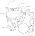
- FIG. 1is a perspective view of a prior art process box (when a first force receiving portion is in a protruding position);
- FIG. 2is a partial structural view of FIG. 1; FIG.
- FIG. 3is an embodiment of a processing box provided by the present application.
- FIG. 4is a partial structural view of a processing box provided by the present application.
- FIG. 5is a cross-sectional view of a process cartridge according to an embodiment provided by the present application.
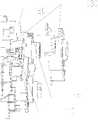
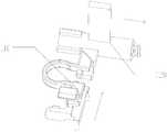
- FIG. 6is a partial structural view of an electronic imaging device
- FIG. 7is a schematic diagram of a process box installation process provided by the present application.
- FIG. 8is a schematic diagram of another installation process of a processing box provided by the present application.
- FIG. 9is a schematic diagram of a working process of a force receiving device provided by the present application.
- FIG. 10is a schematic diagram of another working process of a force receiving device provided by the present application.
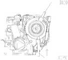
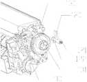
- FIG. 11is a perspective view of another processing box provided by the present application.
- FIG. 12is a structural view of another force receiving device provided by the present application.
- FIG. 13is a structural view of another force receiving device provided by the present application.
- 14ais a state view of another force receiving device provided by the present application.
- FIG. 14bis another state view of another force receiving device provided by the present application.
- FIG. 16is a partial view of another process box provided by the present application.
- FIG. 17is a state before the process cartridge is installed in the electronic imaging device in the fourth embodiment.
- FIG. 18is a perspective view of a first force receiving portion in Embodiment 4.
- 19is a state in which the second force receiving portion interferes with the electronic imaging device when the processing box is installed in the electronic imaging device in the fourth embodiment;
- 21is a state when the processing box is normally ejected when the processing box is taken out of the electronic imaging device with the tray;
- FIG. 23is a perspective view of a processing box in Embodiment 5.
- FIG. 24is a partially enlarged view of FIG. 23; FIG.
- FIG. 28is a schematic diagram of a main working principle of the processing box force receiving device in the fifth embodiment.
- 29is another schematic diagram of the main working principle of the processing box force receiving device in the fifth embodiment.
- FIG. 30is a perspective view of the process box viewed along the process box installation direction in the fifth embodiment.
- FIG. 31is another perspective view of the processing box viewed in the mounting direction of the processing box in the fifth embodiment.
- FIG. 32is a plan view of the process cartridge as viewed from a plane parallel to the mounting direction of the process cartridge in the sixth embodiment;
- FIG. 33is an exploded view of the positional relationship between the first force receiving portion and the support frame in FIG. 32; FIG.
- FIG. 34is a schematic diagram of a working process of a medium force receiving device in Embodiment 6; FIG.
- FIG. 36is another schematic diagram of the working process of the medium force receiving device in Embodiment 6; FIG.
- FIG. 37is another schematic diagram of the working process of the middle force receiving device in Embodiment 6.
- FIG. 37is another schematic diagram of the working process of the middle force receiving device in Embodiment 6.
- FIG. 38is a positional relationship diagram of a third limiting block and a first force receiving portion in the sixth embodiment
- FIG. 40is a schematic structural diagram of a first force receiving portion and a second force receiving portion in the eighth embodiment.
- this embodimentdiscloses a force receiving device.
- the force receiving device of the process boxincludes a second force receiving portion A120 and a first force receiving portion A110, and further includes a first elastic element A140, and the first elastic element A140 abuts on the first force receiving portion A110 and
- the housing of the process boxincluding the first housing A101 and the second housing A102 or a component relatively fixed to the process box, the first force receiving portion A110 is always maintained to protrude from the process box housing under the action of the elastic member Outside the body, and the second force receiving portion can be rotated in the direction of W1 about the axis L2, and the rotation axis L2 is parallel to the length direction (X direction) of the process box; the second force receiving portion A120 can be in the housing of the process box Sliding upward, the sliding direction is perpendicular to the length direction (X direction) of the process box, that is, perpendicular to the rotation axis of the first force receiving portion A110.
- the first casing A101 and the second casing A102 of the process boxcan move relatively, and the force receiving device is disposed on the first casing A101.
- the first elastic element A140may be a torsion spring or a tension spring or a compression spring, and is preferably in the form of a torsion spring.
- the torsion springis used, one end of the first elastic element A140 and the first force receiving portion A110 At least a part of the abutment, the other end abuts at least a part of the first case A101 of the process box, or abuts other components provided on the process box, such as an end cap provided at the end of the process box in the length direction (X direction) .
- the second force receiving portion A120is disposed on the second case A102 and is capable of sliding relative to the first case A101.
- a second elastic element A130is provided between the second force receiving portion A120 and the second case A102. The second force receiving part A120 rebounded.
- the second elastic element A130may also be disposed on a component, such as an end cover, that the second force receiving portion A120 is relatively fixed to the processing box.
- FIG. 5it is a cross-sectional view taken along a length direction (X direction) perpendicular to the process cartridge.
- the first casing A101is provided with a developing element A160
- the second casing A102is provided with a photosensitive element A170.
- the force receiving deviceis disposed on the first casing A101.
- FIG. 7 to FIG. 8a process of installing a process cartridge is shown, and one or more process cartridges are on a mounting bracket of an electronic imaging device.
- the first force receiving portion A110is maintained at an initial position by the action of the first elastic element A140, and the initial position is that the second force receiving portion A120 is relative to the processing box.
- the housing of the housingprotrudes outward, at this time, there is no force between the second force receiving portion A120 and the first force receiving portion A110.
- FIG. 8when the process cartridge is installed in the electronic imaging device in the direction of the arrow shown in FIG.
- the second force receiving portionwill touch the protruding portion 9101 provided in the electronic imaging device.
- the first force receiving portion A110rotates around the axis L2, and the portion protruding outside the process box housing will rotate toward the inside of the process box, that is, move toward the position near the first housing A101 until the protruding portion of the electronic imaging device can be avoided 9101 to facilitate the installation of the process box.
- the protruding portion 9101 in the electronic imaging devicehas no force on the first force receiving portion A110
- the first force receiving portion A110returns to the initial position under the action of the first elastic element A140.
- such a setting mannerdoes not cause the problem that the process cartridge is stuck in the electronic imaging device due to the accidental ejection of the first force receiving portion A110.
- the door of the electronic imaging deviceis closed to start the printing task.
- the first force receiving portion A110is in an initial position; when the printing task is performed, the first force applying part 9201 on the first force applying device 920 provided in the electronic imaging device acts on the second force
- the receiving portion A120slides the second force receiving portion A120 relative to the first housing A101, and the abutting portion A1201 on the second force receiving portion A120 is in abutment with the first force receiving portion A110 to enable the first force receiving Part A110 is stable in the initial position.
- the second force applying device 930further includes a second force applying member 9301 which acts on the left side of the first force receiving portion A110 in a direction perpendicular to the length direction (X direction) of the process box (relative to FIG. 10).
- the first casing A101is rotated relative to the second casing A102, and the developing element A160 and the photosensitive element A170 are moved from a position where they are in contact with each other to a position where they are separated from each other.
- a gap Ncan be formed between the surface of the developing element A160 and the surface of the photosensitive element A170, that is, the roller separation operation is realized.
- the process box tray 910is moved toward the electronic imaging device.
- the first force receiving portion A110cannot be reversely turned in a direction close to the inside of the process box housing, which may cause the first force receiving Part A110 is prone to contact or interfere with the inner surface of the electronic imaging device.
- FIG. 11is a perspective view of the process cartridge provided in this embodiment, wherein the X direction shown in the view is the length direction of the process cartridge, and the Y and Z directions are directions perpendicular to the X direction, respectively.
- the processing box B10includes a first casing B101 and a second casing B102.
- a force receiving deviceis disposed on the processing box B10.
- the force receiving deviceincludes a first force receiving portion B110 and a second force receiving portion. B120 is configured to cooperate with the first force applying member 9201 and the second force applying member 9301 provided in the electronic imaging device, respectively.
- the first force receiving portion B110 and the second force receiving portion B120are respectively disposed on a bracket B140 on which the first casing B101 or the second casing B102 of the process box is relatively fixed, or are disposed on the first On the casing B101 or the second casing B102.
- the force receiving devicefurther includes a first elastic element S1.
- the first elastic element S1is preferably a tension spring component, and of course, it can also be a torsion spring or a compression spring, which is not specifically limited in this application.
- the first elastic element S1can cause the first force receiving portion B110 to protrude beyond the first case B101 without being affected by other external forces.
- this positionis preferably such that a part of the first force receiving portion B110 is in a position protruding outward from the process cartridge housing. 12 and FIG. 13, under the action of the first elastic member S1, the first force receiving portion B110 is in a position protruding to the outside of the process cartridge housing; meanwhile, the first force receiving portion B110 is provided to be able to Rotating around the axis L3, the direction of the axis L3 is parallel to the longitudinal direction (X direction) of the process cartridge housing.
- the process cartridge tray 910When the process cartridge tray 910 is mounted in a direction perpendicular to the length of the process cartridge housing (that is, installed in the Y direction), when a portion of the first force receiving portion B110 protruding outside the process cartridge housing interferes with a portion inside the electronic imaging device Can be rotated around the direction of W2; when the process cartridge tray 910 is taken out in a direction opposite to the Y direction, because the first force receiving portion B110 has interference with a portion in the electronic imaging device, the Direction. In this installation and removal process, the first force receiving portion B110 is closer to the first casing B101 than the positions in FIG. 12 and FIG. 13.
- the technical solution provided in this embodimentdoes not occur when the process box tray 910 is pulled out of the main body of the electronic imaging device.
- the first force receiving portion B110cannot be reversely approached to the process box shell.
- the direction rotation in the body, that is, the processing box in the first embodimentcannot achieve the effect of taking out from the electronic imaging device, and the present application can not only achieve the effect of entering into the electronic imaging device but also take out the electronic imaging device.
- a locking memberis included, and preferably the locking member is the second force receiving portion B120.
- the locking membermay be other locking parts or a self-locking structure. The effect of the second force receiving portion B120 on the first force receiving portion B110 is described below:
- the second force receiving part B120is arranged on the processing box and in the Y direction, and can move in the Y direction under the action of an external force.
- the second force receiving part B120is used to receive the action of the first force applying part 9201 in the electronic imaging device.
- the forceacts on the first force receiving portion B110 through the second force receiving portion B120.
- a second elastic element S2 and a U-shaped structureare provided on the second force receiving portion B120, and the second elastic element S2 is provided in the U-shape.
- the second force receiving portion B120has a certain flexibility.
- the first force applying part 9201 of the electronic imaging deviceapplies the force F1 to the second force receiving part B120
- the first force receiving part B110is caused to slide in the Y direction
- the second force receiving part B120contacts the first force
- the receiving portion B110restricts the rotation of the first force receiving portion B110, that is, the first force receiving portion B110 cannot rotate in a direction close to the second casing B102.
- the end portion B121 of the second force receiving portion B120is inserted into the groove portion B111 of the first force receiving portion B110, so that the first force receiving portion B110 is stabilized at a position protruding outward from the process cartridge housing, and the first force receiving portion No relative movement can occur between B110 and the first casing B101.
- the second force applying member 9301 in the electronic imaging deviceapplies the second force F2 to the first force receiving portion B110, and causes the first case B101 of the process cartridge to rotate relative to the second case B102.
- the force receiving devicefurther includes a third elastic element S3, preferably a compression spring.
- the third elastic element S3is disposed between the second force receiving portion B120 and the bracket B140 or the first casing B101 of the process box. When the force F1 applied by the first force applying member 9201 is cancelled, the third elastic element S3 is used for The second force receiving portion B120 is reset.
- the groove portion B111may also be provided on the second force receiving portion B120, and at the same time, a protruding portion is provided on the first force receiving portion B110 to cooperate with the groove portion B111, so that the first force receiving portion B110 is stabilized at the protruding position, Thus, the first force receiving portion B110 is locked.
- the present inventionalso provides another embodiment, which can simplify the structure of the electronic imaging device.
- An electronic imaging device in the prior artincludes a tray for placing a process cartridge.
- the electronic imaging devicehas a door cover connected to the tray. After the tray is pushed into the electronic imaging device, the electronic imaging device is closed. Door cover, the door cover will drive the tray to move the tray with the processing box placed on the tray down (in the opposite direction of the direction of the Z axis shown in the figure) to complete the installation, and the processing box is in the waiting position position.
- the processing box C10 provided in this embodimentis provided with a second force receiving section C120 and a first force receiving section C110. While the tray drives the processing box to sink along the Z axis, the second force receiving section C120 can be removed from A force is received on a portion 9203 inside the electronic imaging device, and the second force receiving portion C120 is moved upward on the Z axis, and the first force receiving portion C110 is caused to rotate about the axis L4 by the action of the second force receiving portion C120. Turning in the direction of W3, the first force receiving portion C110 is moved from a retracted position to a position protruding outside the process cartridge housing. At this time, the first force receiving portion C110 can receive a second force applying part provided in the electronic imaging device.
- the force of 9301moves the first casing 101 of the process cartridge relative to the second casing 102 to separate the developing roller from the photosensitive drum.
- a first elastic memberis connected to the first force receiving portion C110.
- the first elastic elementmay be a tension spring or a spring. After the processing box is lifted upward in the direction of the Z axis, the second force receiving portion C120 is not affected. The role of the portion 9203 in the electronic imaging device, the first elastic element can reset the first force receiving portion C110.
- the second force receiving portion C120 and the first force receiving portion C110may also be provided in a coordinated action, and the first force receiving portion C110 may be retracted when the first force receiving portion is reset, or a first The two elastic elements are connected to the second force receiving portion C120, and the first force receiving portion C110 is reset by the elastic force.
- the force receiving device involved in this embodimentis an improved version of the force receiving device in Embodiment 2 combined with Embodiment 3.
- the installation direction of the process cartridgeis from left to right in FIG. 17 and FIG. 19 to FIG. 22. That is, after the process cartridge is installed in the process cartridge tray 910 of the electronic imaging device, the tray drives the process cartridge to Install left to right and remove from right to left.
- the structure in this embodimenthas the following modifications:
- the first force receiving portion B110rotates about the axis L3.
- the first housing D101is relative to the second housing during the separation of the rotation axis of the first force receiving portion D110 and the drum in this embodiment.
- the rotation axis L3 of the rotation of the body D102coincides.
- the first force receiving portion D110can be directly sleeved on the existing separating bracket D999 in the prior art to save parts and costs.
- the first force receiving portion B110is connected to the first elastic element S1, and the first elastic element S1 causes the first force receiving portion B110 to be located in a preset without being affected by an external force.
- the positionprotrudes relative to the first case D101.
- the first force receiving portion D110is still connected to the container main body through a first elastic member (not shown in the drawing), but the preset position is closer to the first case. ⁇ D101. As shown in FIG. 17, without being affected by an external force, the first force receiving portion D110 is used to abut the portion of the electronic imaging device—the preset position where the pusher D111 is located is closer to the first relative to the vertical direction. Orientation of case D101.
- the second force receiving portion B120acts on the first force receiving portion B110 after receiving an external force, so that the first force receiving portion B110 can be forced to cause the rollers to separate, and the second force
- the receiving portion B120is also provided with a second elastic element S2 and a third elastic element S3.
- the second force receiving portion D120is no longer set to directly contact the pusher D111 of the first force receiving portion D110, and the first force receiving portion D110 may be annular.
- the center of the ring structureis the rotation axis of the first casing D101 moving around the second casing D102 during the drum separation process, and two protrusions are provided from the first force receiving portion D110, which are the push rod D111, respectively.
- the abutting portion D112is configured to abut the abutting end D121 of the second force receiving portion D120, so as to achieve the purpose of restraining the first force receiving portion D110 by the second force receiving portion D120.
- the second force receiving portion D120no longer receives an external force from the electronic imaging device, but instead relies on the gravity of the process cartridge itself.
- the second force receiving portion D120is similar to the second force receiving portion B120 in the second embodiment, and may also be disposed on the first casing D101. At the same time, the second force receiving portion D120 is no longer provided with the second elastic element S2 and the third elastic element S3, and its specific structure will be more clearly explained with the following state.
- FIG. 17shows a state before the process cartridge is installed in the electronic imaging device.
- This viewis a view obtained by observing the side wall of the processing box near the side of the force receiving device, as shown in FIG. 17.
- the first force receiving portion D110can be freely opposed to Its rotation axis swings without being restricted by the second force receiving portion D120.
- the first force receiving portion D110protrudes relative to the first frame D101.
- an arc-shaped swing restraint D190is further provided on the processing box.
- the swing restraint D190includes a first end D191 and a second end D192, and the first end D191 and the second end D192 may be respectively connected with the first force.
- the receiving portion D110contacts to restrain the swing angle of the first force receiving portion D110.
- the swing restraint D190is disposed on the first case D101.
- FIG. 18is a perspective view of the second force receiving portion D120.
- the second force receiving portion D120includes an abutting end D121 abutting on the abutting portion D112, a pushing end D122 located at an opposite end of the abutting end D121, and a second elastic member (not shown in the figure) ) Contact end D123.
- One end of the second elastic memberis in contact with the contact end D123, and the other end is in contact with the process cartridge main body.
- the second elastic memberdoes not generate an elastic force or generates an elastic force that moves the second force receiving portion D120 away from the first force receiving portion D110 without being subjected to an external force.
- FIG. 19is a state in which the first force receiving portion D110 interferes with the electronic imaging device when the process cartridge is installed in the electronic imaging device.
- the processing boxis installed on the tray, and the processing box is installed in a direction in which the first casing D101 is front and the second casing D102 is rear (that is, moving from left to right in FIG. 19). Since the second force receiving portion D120 has not been pushed and / or moved to a position constraining the first force receiving portion D110, the first force receiving portion D110 can swing relatively freely, as shown in the figure, swinging closer to the first housing D101 Position, so that it can be smoothly installed into the electronic imaging device. After the process cartridge is installed into the electronic imaging device with the tray 910, the first elastic member pulls and pushes the first force receiving portion D110 to return to the state shown in FIG.
- FIG. 20shows the state of the electronic imaging device after the door is closed after the process cartridge is installed in the electronic imaging device, and the door is closed at this time.
- the tray containing the process boxis lowered horizontally in the vertical direction.
- the pushing tube D122 of the second force receiving portion D120gradually comes into contact with the inside of the electronic imaging device, and under the pressure of the gravity of the process box, the second force receiving portion D120 is moved in the direction of the first force receiving portion D110 and compresses the first Two elastic pieces.
- the second force receiving portion D120moves into position. At this time, as in the state in FIG.
- the first force receiving portion D110is restrained by the second force receiving portion D120, so that the first The force receiving portion D110 cannot swing freely in the counterclockwise direction in FIG. 20, that is, the push rod D111 cannot move freely in the direction of the second casing D102.
- the electronic imaging deviceexerts a force directed on the push rod D111 in the direction of the second casing D102, that is, the first casing D101 can be rotated relative to the second casing D102 to complete the roller separation.
- FIG. 21is a state when the second force receiving portion D120 is normally ejected when the processing box is removed from the electronic imaging device with the tray
- FIG. 22is a state when the second force receiving portion D120 is not normally ejected when the processing box is removed from the electronic imaging device with the tray. status.
- the first force receiving portion D110is a state protruding relative to the first case D101.
- the second pushing portion D110interferes with the electronic imaging device, and swings in a clockwise direction (that is, forces the push rod D111 to move in the direction of the first housing D101) to be smoothly taken out.
- the technical solution provided in this embodimentdoes not occur when the process box tray 910 is pulled out of the main body of the electronic imaging device.
- the first force receiving portion D110cannot be reversely approached to the process box shell.
- the direction rotation in the body, that is, the processing box in the first embodimentcannot achieve the effect of taking out from the electronic imaging device, and the present application can not only achieve the effect of entering into the electronic imaging device but also take out the electronic imaging device.
- the malfunctioning process cartridgewas reinstalled into the electronic imaging device.
- the interference process cartridgeespecially the first force receiving portion D110, could no longer reach the position in FIG. 19, it could not be installed in the image forming apparatus. Therefore, such a design implements a function of automatically checking for failures, preventing the problem that the electronic imaging device cannot be used due to the failure of the process cartridge to fail inside the electronic imaging device in other cases.
- FIG. 23is a perspective view of the process cartridge in this embodiment
- FIG. 24is a partially enlarged view of FIG. 23.
- FIG. 24is a part of the right end portion in FIG. 23.
- the force receiving deviceis located on the right side of the process cartridge with respect to the mounting direction of the process cartridge and near the front of the mounting direction. After the force receiving device is installed in the electronic imaging device, it is located on the same side as the first force applying device 920 and the second force applying device 930 inside the electronic imaging device.
- the process boxincludes a second force receiving portion 110, a first force receiving portion 120, and a support frame 130 that supports the second force receiving portion 110 and / or the first force receiving portion 120.
- the second force receiving portion 110may be in contact with and pushed by the first force applying device 920 of the electronic imaging device, and the first force receiving portion 120 may be in contact with and be pushed by the second force applying device 930 of the electronic imaging device.
- the second force applying device 930pushes.
- the first force receiving portion 120includes an elastic member 121.
- the elastic member 121can push the first force receiving portion 120 to move away from the right end of the processing box. Therefore, the first force receiving portion 120 is not subject to external force. In this case, it is located away from the right end of the process cartridge, as shown in FIG. 25.
- the elastic membercan also be disposed on the side of the first force receiving portion 120 near the left end portion of the process cartridge and pull the first force receiving portion 120 to move toward the left end portion.
- the first force receiving portion 120further includes a limiting portion 122, so that the first force receiving portion 120 can only perform translation in the length direction of the process box.
- the limiting portion 122is a cross projection
- the support frame 130includes a cross groove 131.
- the first force receiving portion 120can only be flat along the length of the processing box through the engagement of the limit portion 122 and the cross groove 131. As shown in Figure 26.
- the number of grooves and bumpscan also be appropriately increased or reduced, or other existing technologies in the mechanical field can be used to keep the first force receiving portion 120 only capable of translation in the length direction of the process box. This embodiment only introduces one This process is a relatively simple and preferred scheme.
- FIG. 27is an exploded view, which mainly illustrates how the second force receiving portion 110 is fixed on the support frame 130. By engaging the groove 132 in the figure with the second force receiving portion 110, the second force receiving portion 110 can only be translated in the process cartridge mounting direction.
- Figures 28 and 29are schematic diagrams of the main working principles of a force receiving device for a process cartridge.
- the second force receiving portion 110includes a pushing block 112, which is a right-angled triangle, the narrower the right-angled triangle is closer to the front of the process box installation direction and the beveled side faces near the right end of the process box;
- the force receiving part 120includes a receiving block 123.
- the receiving block 123is a right-angled triangle. The closer to the front of the process box installation direction, the wider the front side is, and the hypotenuse faces the position near the left end of the process box.
- the pushing block 112does not push the receiving block 123; when the processing box is in the electronic imaging device
- the first force applying device 920 of the electronic imaging devicepushes the second force receiving portion 111 on the second force receiving portion 110, so that the entire second force receiving portion is translated in the mounting direction of the process box.
- the hypotenuse of the pushing block 112is coupled with the hypotenuse of the receiving block 123, thereby pushing the first force receiving part 120 to the right end of the processing box, as shown in FIG. 29, and finally making the first force receiving part 120 the first A force receiving portion 124 is in a position where it can be pushed by the second force applying device 930 in the electronic imaging device.
- the second force receiving portion 110When the process box is used up and removed from the electronic imaging device, the second force receiving portion 110 is no longer pressed by the first pushing portion after the door of the electronic imaging device is opened, so the elastic member 121 can push the first force receiving portion 120 Move in a direction away from the right end of the process box, and push the second force receiving section 110 in the opposite direction of the process box installation direction by the abutment of the receiving block 123 and the slanting surface of the pushing block 112, returning to the status.
- a buffer portion 113is further provided on the second force receiving portion 110 to prevent it from being stuck during work.
- the buffer portion 113has a U-shaped structure, and a spring is provided at the U-shaped mouth thereof, so that the second force receiving portion 110 is forced to push and move in a certain amount of space during the translation process.
- FIG. 30 and 31are perspective views of the process cartridge as viewed in the process cartridge mounting direction.
- FIG. 30corresponding to the state in FIG. 28, in the process of installing the processing box into the electronic imaging device, the interference between the first force receiving portion 124 and the second force applying device 930 can be effectively avoided, and the processing box is prevented from being loaded.
- Figure 31corresponds to the state in Figure 29, at this time the process box has been installed in place and the electronic imaging device has closed the door cover.
- the second force application device 930pushes the first force
- the movement of the portion 124 in the reverse direction of the process cartridge installation directioncan separate the rollers according to the principle of lever.
- the electronic imaging deviceAfter the processing box is installed in the electronic imaging device, the electronic imaging device first checks the powder box. During this process, the second force applying device 930 moves a distance along the mounting direction of the processing box. After the inspection is completed, once the processing box is required to be separated from the drum, the second force applying device 930 will move in a direction opposite to the mounting direction of the processing box and push the processing box to be separated from the drum.
- This embodimentprovides a processing box, and the unexplained parts are the same as those in the fifth embodiment.
- Fig. 32is a plan view of the process cartridge as viewed in a plane parallel to the mounting direction of the process cartridge.
- the process box in this embodimentincludes a second force receiving section 210, which is similar to the second force receiving section 110 in Embodiment 1, and can only be translated in the process box installation direction and its opposite direction;
- a force receiving portion 220in this embodiment, viewed from the top of the process box (a surface parallel to the length direction of the process box and the mounting direction of the process box, that is, the angle of view in FIG. 32), the first force receiving portion 220 may be clockwise Or turn counterclockwise.
- the clockwise and / or counterclockwise descriptions of the first force receiving portion 220 in this embodimentall adopt the viewing angle in FIG. 32 as a standard.
- the processing boxfurther includes a support frame 230, which includes a convex support shaft 231 that supports the rotation of the first force receiving portion 220, and preferably further includes a first limit block 232 and a second limit block that limit the range of movement of the first force receiving portion 220.
- Limit block 233Limit block 233.
- FIG. 33is an exploded view of the positional relationship of the first force receiving portion 220 and the support frame 230.
- An elastic member 221pushes the first force receiving portion 220, so that the first force receiving portion 220 has a tendency to rotate counterclockwise.
- the elastic member 221is a torsion spring, one leg of the torsion spring is connected to the first force receiving portion 220, and the other end is connected to the main body of the process box or other components provided on the process box.
- the torsion spring 221 and the first force receiving portion 220are both sleeved on the convex support shaft 231.
- the second force receiving portion 210is similar to that in the first embodiment, and each includes a second force receiving portion 211 and a buffer portion 213.
- the pushing block 212is different in shape from the pushing block 112 in the first embodiment, but both are for pushing the first force receiving portion 220.
- the first force receiving portion 220includes a receiving block 223 that is in contact with and pushed by the pushing block 212, a ring 222 sleeved on the convex support shaft 231, and a first force receiving portion 224 that is in contact with the second force applying device 930.
- FIG. 34shows the states of the components when the process cartridge is not installed in the electronic imaging device and when the process cartridge is installed in the electronic imaging device.
- the second force receiving portion 210is not in contact with the first force receiving portion 220. Due to the action of the elastic member 221, the first force receiving portion 220 has a tendency to rotate counterclockwise, but because the first limit block 232 and the receiving block 223 abuts, and the second limit block 233 abuts the first force receiving portion 224, so the first force receiving portion 220 cannot continue to rotate counterclockwise.
- the first force receiving portion 224does not contact the second force applying device 930, interference problems can be effectively avoided.
- FIG. 35shows a state after the door of the electronic imaging device is closed.
- the second force receiving portion 210is pushed for translation in the process cartridge mounting direction, and the first force receiving portion 220 is pushed.
- the buffer portion 213 on the second force receiving portion 210functions and deforms, and the spring therein is compressed, so that the door of the electronic imaging device can be smoothly closed.
- FIG. 36is a state when the electronic imaging device is inspected.
- the second force applying device 930moves in the process cartridge installation direction, thereby avoiding the position where the first force receiving portion 220 rotates clockwise, and the first force receiving portion 220 is rotated to Position in Figure 36.
- the electronic imaging devicecontrols the second force applying device 930 to move in a direction opposite to the installation direction of the process box to push the first force receiving portion 220 (the contact position is the first force receiving portion 224), thereby Drum separation is performed as shown in FIG. 27.
- a third limiting block 234is further provided on the support frame 230.
- the third limit block 234is configured to be in contact with the first force receiving portion 224 when the second force receiving portion 210 pushes the first force receiving portion 220 to the extreme position in the state shown in FIG. 36 and FIG. 37. As shown in FIG. 38, the force during the separation of the rollers is stabilized.
- a modificationcan be made, that is, the first force receiving portion 220 is rotated counterclockwise.
- the first force receiving portion 224does not point toward the front of the process box installation direction but instead points in the second embodiment.
- the pushing block 212 and the receiving block 223are provided on the left side of the ring 222, and the torsion spring position of the elastic member 221 is adjusted accordingly, so that the mirror flip can be realized, and the first force receiving part during the installation process 220 rotates counterclockwise.
- the block that is translated in the lengthwise direction of the process box in the first embodimentmay be combined to install The rear of the direction abuts against the first force receiving portion 224, or a third limiting block 234 which is retractable relative to the main body of the process box is provided. Both the translational and telescopic blocks are pushed for telescopic or translational movement during the movement of the second force receiving portion 210.
- This embodimentis further improved based on the actual condition of trial production on the basis of the sixth embodiment.
- FIG. 39is a schematic structural diagram of a processing box in this embodiment. Only the right part of the drum separation structure was taken out.
- the process cartridge in this embodimentincludes a second force receiving portion 310 and a first force receiving portion 320 that acts on the second force applying device 930.
- This embodimentfurther includes a detachment preventing portion 340, and at least a part of the projection of the detachment preventing portion 340 in the length direction of the processing box coincides with the first force receiving portion 320.
- the detachment prevention portion 340is used to prevent the first force receiving portion 320 from coming out of the process cartridge during the rotation.
- the anti-detachment portion 340is located on the first casing 1101 and protrudes from the first casing 1101 in a direction away from the process box.
- FIG. 40is a schematic structural diagram of a first force receiving portion and a second force receiving portion in this embodiment.
- a new buffer portion 313is provided in this embodiment.
- the buffer portion 213acts similarly, except that the shape is slightly changed from the original "C” type to "S" type.
- Such a designcan enable the buffer portion 313 to withstand a larger amount of deformation and make the component more stable when it works.
Landscapes
- Engineering & Computer Science (AREA)
- Computer Vision & Pattern Recognition (AREA)
- Physics & Mathematics (AREA)
- General Physics & Mathematics (AREA)
- Electrophotography Configuration And Component (AREA)
Abstract
Description
Translated fromChinese本申请要求于2018年09月21日提交中国专利局、申请号为201821557706.8、申请名称为“力接收装置及包含力接收装置的处理盒”的中国专利申请、2019年02月20日提交中国专利局、申请号为201920230183.4、申请名称为“力接收装置及包含该力接收装置的处理盒”的中国专利申请、2019年03月29日提交中国专利局、申请号为201920419854.1、申请名称为“力接收装置及包含该力接收装置的处理盒”的中国专利申请、2019年05月29日提交中国专利局、申请号为201920791621.4、申请名称为“力接收装置及包含该力接收装置的处理盒”的中国专利申请、2019年05月31日提交中国专利局、申请号为201920811604.2、申请名称为“力接收装置及包含该力接收装置的处理盒”的中国专利申请和2019年06月24日提交中国专利局、申请号为201910547647.9、申请名称为“处理盒”的中国专利申请的优先权,其全部内容通过交叉引用结合在本申请中。This application requires a Chinese patent application filed with the Chinese Patent Office on September 21, 2018, with an application number of 201821557706.8 and an application name of "Power Receiving Device and Processing Box Containing a Force Receiving Device", and a Chinese Patent Application on February 20, 2019 Office, Chinese Patent Application No. 201920230183.4, Application Name "Power Receiving Device and Processing Box Containing the Force Receiving Device", filed with China Patent Office on March 29, 2019, Application No. 201920419854.1, and Application Name "Power "Receiving device and processing box containing the force receiving device" Chinese patent application, filed with the Chinese Patent Office on May 29, 2019, application number 201920791621.4, and the application name is "Power receiving device and processing box containing the force receiving device" Chinese patent application, filed on May 31, 2019, Chinese Patent Office, application number 201920811604.2, application name "Power Receiving Device and Processing Box Containing the Power Receiving Device" and filed on June 24, 2019 Priority of Chinese Patent Application of the Chinese Patent Office, Application No. 201910547647.9, and Application Name as "Processing Box" Unit is incorporated herein by cross-reference.
本申请涉及成像装置技术领域,尤其涉及一种处理盒。The present application relates to the technical field of imaging devices, and in particular, to a process cartridge.
电子成像装置是通过电照相成像处理技术在记录材料上形成图像的设备,例如:电子照相复印件、激光打印机、电子照相打印机、传真机、文字处理机等。电子成像装置通常包括单色电子成像装置和彩色电子成像装置。An electronic imaging device is a device that forms an image on a recording material by an electrophotographic imaging processing technique, such as an electrophotographic copy, a laser printer, an electrophotographic printer, a facsimile machine, a word processor, and the like. Electronic imaging devices generally include monochrome electronic imaging devices and color electronic imaging devices.
现有的电子成像装置包括主体,以及可拆卸的安装到主体内的处理盒。处理盒沿其长度方向的两端设置有侧壁。处理盒内部通常包括有旋转部件,旋转部件为感光元件,显影元件,充电元件,送粉元件,齿轮部件等中的一个或多个。其中,旋转元件可以与动力接收部件相连接,并从动力接收部件接收驱动力。动力接收部件通常设置在处理盒的一侧侧壁上,并从电子成像装置的主体接收驱动力。The existing electronic imaging device includes a main body, and a processing box detachably mounted in the main body. The processing box is provided with side walls at both ends along its length direction. The inside of the processing box usually includes a rotating member, and the rotating member is one or more of a photosensitive member, a developing member, a charging member, a powder feeding member, a gear member, and the like. Among them, the rotating element may be connected to the power receiving part and receive a driving force from the power receiving part. The power receiving member is generally provided on a side wall of the process cartridge and receives a driving force from the main body of the electronic imaging device.
当处理盒不进行电子成像工作时,为了保护显影元件和感光元件,通常将两者分离,即显影元件和感光元件在不进行电子成像时不相接触。When the process cartridge does not perform the electronic imaging work, in order to protect the developing element and the photosensitive element, the two are usually separated, that is, the developing element and the photosensitive element are not in contact with each other when electronic imaging is not performed.
现有技术中(例如公开号为CN101963779A的专利),如图1至图2所示,处理盒的壳体上有力接收装置。具体的,处理盒包括第一壳体1101以及第二壳体1102,力接收装置包括第一力接收部分110和第二力接收部分1120。其中,第一力接收部分1110具有待命位置和突出位置两种状态,处于待命位置(处理盒处于尚未安装或安装过程中的位置)时,此时第一力接收部分1110是设置在第一壳体1101内部的;而处于突出位置(处理盒处于安装后的工作位置)时,此时第一力接收部分1110是突出第一壳体1101设置的(参见图1和图2)。第二力接收部分1120能够接收来自电子成像装置中的第一迫推力,并推动第一力接收部分1110转动至突出在处理盒外部的位置,在电子成像装置执行打印工作时,电子成像装置内设置有第二迫推力作用于第一力接收部分1110,并使处理盒的第一壳体相对于处理盒的第二壳体转动。参见图2,现有技术中,第一力接收部分1110被第二力接收部分1120的推动作用后能够绕轴转动,当第二力接收部分120不再抵接第一力接收部分1110后第一力接收部分1110自动缩回。轴线L1与处理盒的长度方向垂直。In the prior art (for example, the patent with publication number CN101963779A), as shown in FIGS. 1 and 2, the housing of the processing box has a powerful receiving device. Specifically, the process box includes a
图6所示为一种电子成像装置900,其包括处理盒托盘910、第一力施加装置920和第二力施加装置930,第一力施加装置920能够给第二力接收部分120施加迫推力,第二力施加装置930可以给第一力接收部分110施加迫推力。当处理盒安装进电子成像装置时,四个不同颜色的处理盒按照顺序安装在处理盒托盘910上,并处理盒托盘910推入电子成像装置900后,电子成像装置完成工作处于待机状态时,第一力施加装置920作用于第二力接收部分1120,再通过第二力接收部分1120推动第一力接收部分1110伸出,从而第一力接收部分1110被第二力施加部分930迫推并使第一壳体1101相对于第二壳体1102转动。FIG. 6 shows an
在现有的技术中粉盒在处理盒托盘910上向电子成像装置900的安装过程中,由于在尚未安装或安装过程中的位置时,第一力接收部分1110是设置在第一壳体1101内部的,如此不会对正常的安装动作产生影响。但是,由于与第一力接收部分1110配合的连接件在多次使用过程后,可能造成无法使第一力接收部分1110准确地位于第一壳体1101内,即有可能导致第一力接收 部分1110意外伸出,从而造成卡死无法正常的将托盘910推入电子成像装置900,进而无法正常的进行电子成像活动;同时由于现有技术中的第二力接收部分1120和第一力接收部分1110联动,因此倘若在电子成像装置900内部发生卡死,将会造成无法取出处理盒的问题。因此有必要设计一种新的力接收装置以代替原有的力接收装置。In the prior art, in the process of installing the toner cartridge on the
申请内容Application content
本申请提供了一种处理盒,以解决可能因第一力接收部分意外伸出而导致处理盒卡死在电子成像装置内的问题。The present application provides a processing box to solve the problem that the processing box may be stuck in the electronic imaging device due to the accidental extension of the first force receiving portion.
本申请提供了一种处理盒,所述处理盒可拆卸地安装于电子成像装置中,所述电子成像装置包括第一力施加部件,处理盒包括:The application provides a processing box, which is detachably mounted in an electronic imaging device, the electronic imaging device includes a first force applying part, and the processing box includes:
显影辊和支撑所述显影辊的第一壳体;A developing roller and a first casing supporting the developing roller;
感光鼓和支撑所述感光鼓的第二壳体;A photosensitive drum and a second casing supporting the photosensitive drum;
第一力接收部分,所述第一力接收部分可以与所述第一力施加部件接触;A first force receiving portion, which may be in contact with the first force applying member;
所述第一力接收部分具有多个位置状态,当位于第一位置状态时,所述第一力接收部分相对于所述第一壳体突出;当位于第二位置状态时,相比所述第一位置状态时所述第一力接收部分更靠近所述第一壳体;The first force receiving portion has a plurality of position states, and when in the first position state, the first force receiving portion projects relative to the first housing; when in the second position state, compared to the The first force receiving portion is closer to the first housing in the first position state;
所述处理盒包括第一弹性件,所述第一弹性件可以使所述第一力接收部分维持在所述第一位置状态。The processing box includes a first elastic member, and the first elastic member can maintain the first force receiving portion in the first position.
优选地,当所述第一力施加部件推动所述第一力接收部分进行辊鼓分离时,所述第一力接收部分位于所述第一位置状态。Preferably, when the first force applying member pushes the first force receiving portion for drum separation, the first force receiving portion is located in the first position state.
优选地,所述处理盒包括锁定件,当所述处理盒进行辊鼓分离时,所述锁定件被配置为约束所述第一力接收部分运动。Preferably, the processing box includes a locking member configured to restrain the first force receiving portion from moving when the processing box is subjected to drum separation.
优选地,所述锁定件为第二力接收部分。Preferably, the locking member is a second force receiving portion.
优选地,所述电子成像装置还包括第二力施加部件,所述第二力接收部分可以与所述第二力施加部件接触,以使所述第二力接收部分约束所述第一力接收部分运动。Preferably, the electronic imaging device further includes a second force applying part, and the second force receiving part may be in contact with the second force applying part so that the second force receiving part restricts the first force receiving Part of the movement.
优选地,所述处理盒还包括第二弹性件,所述第二弹性件可以使所述第二力接收部分脱离与所述第一力接收部分的接触。Preferably, the process box further includes a second elastic member, which can disengage the second force receiving portion from contact with the first force receiving portion.
一种处理盒,所述处理盒可拆卸地安装于电子成像装置中,所述电子成像装置包括第一力施加部件,处理盒包括:A processing box is detachably installed in an electronic imaging device, the electronic imaging device includes a first force applying part, and the processing box includes:
显影辊和支撑所述显影辊的第一壳体;A developing roller and a first casing supporting the developing roller;
感光鼓和支撑所述感光鼓的第二壳体;A photosensitive drum and a second casing supporting the photosensitive drum;
第一力接收部分,所述第一力接收部分可以与所述第一力施加部件接触;A first force receiving portion, which may be in contact with the first force applying member;
所述第一力接收部分具有多个位置状态,当位于第一位置状态时,所述第一力接收部分相对于所述第一壳体突出且可以转动;当位于第二位置状态时,所述第一力接收部分相对于所述第一壳体突出且所述第一力接收部分与所述第一壳体之间不能发生相对运动;当位于第三位置状态时,相比所述第一位置状态或所述第二位置状态时所述第一力接收部分更靠近所述第一壳体;The first force receiving portion has a plurality of position states. When the first force receiving portion is in the first position state, the first force receiving portion projects relative to the first housing and is rotatable; when in the second position state, all the The first force receiving portion protrudes relative to the first housing and relative movement cannot occur between the first force receiving portion and the first housing; when in a third position state, compared to the first position The first force receiving portion is closer to the first housing in a position state or the second position state;
所述处理盒包括第一弹性件,所述第一弹性件可以使所述第一力接收部分维持在所述第一位置状态;The processing box includes a first elastic member, and the first elastic member can maintain the first force receiving portion in the first position state;
当所述第一力施加部件推动所述第一力接收部分进行辊鼓分离时,所述第一力接收部分位于所述第二位置状态。When the first force applying member pushes the first force receiving portion for drum separation, the first force receiving portion is in the second position state.
优选地,所述处理盒包括锁定件,当所述第一力接收部分位于所述第二位置状态时,所述锁定件被配置为约束所述第一力接收部分运动。Preferably, the processing box includes a locking member configured to restrain the first force receiving portion from moving when the first force receiving portion is located in the second position state.
优选地,所述锁定件为第二力接收部分。Preferably, the locking member is a second force receiving portion.
优选地,所述电子成像装置还包括第二力施加部件,所述第二力接收部分可以与所述第二力施加部件接触,以使所述第二力接收部分约束所述第一力接收部分运动。Preferably, the electronic imaging device further includes a second force applying part, and the second force receiving part may be in contact with the second force applying part so that the second force receiving part restricts the first force receiving Part of the movement.
优选地,所述处理盒还包括第二弹性件,所述第二弹性件可以使所述第二力接收部分脱离与所述第一力接收部分的接触。Preferably, the process box further includes a second elastic member, which can disengage the second force receiving portion from contact with the first force receiving portion.
优选地,所述处理盒还包括摆动约束件,所述摆动约束件具有第一端和第二端,所述第一力接收部分可以在所述第一端和所述第二端内转动;Preferably, the process box further includes a swing restraint having a first end and a second end, and the first force receiving portion can be rotated within the first and second ends;
当位于所述第一位置状态或所述第二位置状态时,所述第一力接收部分位于所述第一端和所述第二端之间;当位于所述第三位置状态时,所述第一力接收部分可以与所述第一端或所述第二端接触。When in the first position state or the second position state, the first force receiving portion is located between the first end and the second end; when in the third position state, all The first force receiving portion may be in contact with the first end or the second end.
优选地,所述第一力接收部分包括:Preferably, the first force receiving portion includes:
迫推杆,可以在所述第一端和所述第二端内转动,且可以与所述第一力施加部件接触;The push rod can be rotated within the first end and the second end, and can be in contact with the first force applying member;
抵接部,位于所述第一端和所述第二端的外部且可以与锁定件接触;An abutting portion, which is located outside the first end and the second end and can be in contact with the locking member;
当所述第一力接收部分位于所述第二位置状态时,所述锁定件被配置为约束所述抵接部运动。When the first force receiving portion is in the second position state, the locking member is configured to restrain the abutting portion from moving.
优选地,所述锁定件为第二力接收部分,所述第二力接收部分包括:Preferably, the locking member is a second force receiving portion, and the second force receiving portion includes:
抵接端,可以与所述抵接部抵接;The abutting end may be in abutment with the abutting portion;
推动端,与所述抵接端连接且可以与第二力施加部件接触;The pushing end is connected with the abutting end and can be in contact with the second force applying member;
所述第二力施加部件可以推动所述推动端,以使所述抵接端约束所述抵接部运动。The second force applying member may push the pushing end, so that the abutting end restrains the abutting portion from moving.
优选地,所述第二力接收部分还包括接触端,所述接触端可与第二弹性件接触,所述第二弹性件可以使所述抵接端脱离与所述抵接部的接触。Preferably, the second force receiving portion further includes a contact end, the contact end may be in contact with a second elastic member, and the second elastic member may release the abutting end from contact with the abutting portion.
一种处理盒,所述处理盒可拆卸地安装于电子成像装置中,所述电子成像装置包括第一力施加部件,处理盒包括:A processing box is detachably installed in an electronic imaging device, the electronic imaging device includes a first force applying part, and the processing box includes:
显影辊和支撑所述显影辊的第一壳体;A developing roller and a first casing supporting the developing roller;
感光鼓和支撑所述感光鼓的第二壳体;A photosensitive drum and a second casing supporting the photosensitive drum;
第一力接收部分,所述第一力接收部分可以与所述第一力施加部件接触;A first force receiving portion, which may be in contact with the first force applying member;
所述第一力接收部分可以沿平行于所述处理盒长度方向的旋转轴旋转到多个位置状态,当位于第一位置状态时,所述第一力接收部分相对于所述第一壳体突出;当位于第二位置状态时,相比所述第一位置状态时所述第一力接收部分更靠近所述第一壳体;The first force receiving portion can be rotated to a plurality of position states along a rotation axis parallel to the length direction of the process cartridge. When in the first position state, the first force receiving portion is relative to the first housing. Protruding; when in the second position, the first force receiving portion is closer to the first housing than when in the first position;
当所述第一力施加部件推动所述第一力接收部分进行辊鼓分离时,所述第一力接收部分位于所述第一位置状态。When the first force applying member pushes the first force receiving portion for drum separation, the first force receiving portion is in the first position state.
优选地,所述处理盒包括锁定件,当所述第一力接收部分位于所述第一位置状态时,所述锁定件被配置为约束所述第一力接收部分运动。Preferably, the process cartridge includes a locking member configured to restrain the first force receiving portion from moving when the first force receiving portion is located in the first position state.
优选地,所述锁定件为第二力接收部分。Preferably, the locking member is a second force receiving portion.
优选地,所述电子成像装置还包括第二力施加部件,所述第二力接收部分可以与所述第二力施加部件接触,以使所述第二力接收部分约束所述第一力接收部分运动。Preferably, the electronic imaging device further includes a second force applying part, and the second force receiving part may be in contact with the second force applying part so that the second force receiving part restricts the first force receiving Part of the movement.
优选地,所述处理盒包括第一弹性件,所述第一弹性件可以使所述第一力接收部分维持在所述第一位置状态。Preferably, the process box includes a first elastic member, and the first elastic member can maintain the first force receiving portion in the first position state.
优选地,所述处理盒还包括第二弹性件,所述第二弹性件可以使所述第二力接收部分脱离与所述第一力接收部分的接触。Preferably, the process box further includes a second elastic member, which can disengage the second force receiving portion from contact with the first force receiving portion.
一种处理盒,所述处理盒可拆卸地安装于电子成像装置中,所述电子成像装置包括第一力施加部件,处理盒包括:A processing box is detachably installed in an electronic imaging device, the electronic imaging device includes a first force applying part, and the processing box includes:
显影辊和支撑所述显影辊的第一壳体;A developing roller and a first casing supporting the developing roller;
感光鼓和支撑所述感光鼓的第二壳体;A photosensitive drum and a second casing supporting the photosensitive drum;
第一力接收部分,所述第一力接收部分可以与所述第一力施加部件接触;A first force receiving portion, which may be in contact with the first force applying member;
所述第一力接收部分可以沿旋转轴旋转到多个位置状态,当位于第一位置状态时,所述第一力接收部分相对于所述第一壳体突出;当位于第二位置状态时,相比所述第一位置状态时所述第一力接收部分更靠近所述第一壳体;The first force receiving portion can be rotated to a plurality of position states along a rotation axis. When located in the first position state, the first force receiving portion projects relative to the first housing; when in the second position state, , The first force receiving portion is closer to the first casing than in the first position state;
所述处理盒包括第一弹性件,所述第一弹性件可以使所述第一力接收部分维持在所述第一位置状态;The processing box includes a first elastic member, and the first elastic member can maintain the first force receiving portion in the first position state;
所述处理盒包括锁定件,当所述第一力接收部分位于所述第二位置状态时,所述锁定件至少可以在一个旋转方向上约束所述第一力接收部分运动。The processing box includes a locking member, and when the first force receiving portion is located in the second position, the locking member can restrain the first force receiving portion from moving in at least one rotation direction.
优选地,所述锁定件为第二力接收部分。Preferably, the locking member is a second force receiving portion.
优选地,所述电子成像装置还包括第二力施加部件,所述第二力接收部分可以与所述第二力施加部件接触,以使所述第二力接收部分约束所述第一力接收部分运动。Preferably, the electronic imaging device further includes a second force applying part, and the second force receiving part may be in contact with the second force applying part so that the second force receiving part restricts the first force receiving Part of the movement.
优选地,所述处理盒还包括第二弹性件,所述第二弹性件可以使所述第二力接收部分脱离与所述第一力接收部分的接触。Preferably, the process box further includes a second elastic member, which can disengage the second force receiving portion from contact with the first force receiving portion.
本申请提供的处理盒中的第一力接收部分具有多个位置状态,其中位于第二位置状态时,相比第一位置状态时第一力接收部分更靠近第一壳体,如此可避免因第一力接收部分意外伸出而导致处理盒卡死在电子成像装置内的问题。The first force receiving portion in the processing box provided in the present application has multiple position states. When the first force receiving portion is located in the second position state, the first force receiving portion is closer to the first housing than in the first position state. The problem that the first force receiving portion is accidentally extended causes the process cartridge to jam in the electronic imaging device.
应当理解的是,以上的一般描述和后文的细节描述仅是示例性的,并不能限制本申请。It should be understood that the above general description and the following detailed description are merely exemplary, and should not limit the present application.
图1为现有技术一种处理盒(第一力接收部分处于突出位置时)的立体视图;1 is a perspective view of a prior art process box (when a first force receiving portion is in a protruding position);
图2为图1的部分结构视图;FIG. 2 is a partial structural view of FIG. 1; FIG.
图3为本申请提供的一种处理盒的实施方式;FIG. 3 is an embodiment of a processing box provided by the present application; FIG.
图4为本申请提供的一种处理盒的部分结构视图;4 is a partial structural view of a processing box provided by the present application;
图5为本申请提供的实施方式的处理盒的剖面视图;5 is a cross-sectional view of a process cartridge according to an embodiment provided by the present application;
图6为电子成像装置的部分结构视图;6 is a partial structural view of an electronic imaging device;
图7为本申请提供的一种处理盒安装过程示意图FIG. 7 is a schematic diagram of a process box installation process provided by the present application
图8为本申请提供的一种处理盒另一安装过程示意图;8 is a schematic diagram of another installation process of a processing box provided by the present application;
图9为本申请提供的一种力接收装置工作过程示意图;9 is a schematic diagram of a working process of a force receiving device provided by the present application;
图10为本申请提供的一种力接收装置的另一种工作过程示意图。FIG. 10 is a schematic diagram of another working process of a force receiving device provided by the present application.
图11为本申请提供的又一种处理盒的立体视图;FIG. 11 is a perspective view of another processing box provided by the present application; FIG.
图12为本申请提供的又一种力接收装置的结构视图;12 is a structural view of another force receiving device provided by the present application;
图13为本申请提供的又一种力接收装置的结构视图;13 is a structural view of another force receiving device provided by the present application;
图14a为本申请提供的又一种力接收装置的一种状态视图;14a is a state view of another force receiving device provided by the present application;
图14b为本申请提供的又一种力接收装置的另一种状态视图;FIG. 14b is another state view of another force receiving device provided by the present application; FIG.
图15为本申请提供的处理盒的横切面视图;15 is a cross-sectional view of a process cartridge provided by the present application;
图16为本申请提供的又一种处理盒的部分视图;FIG. 16 is a partial view of another process box provided by the present application; FIG.
图17为实施例四中处理盒安装进电子成像装置前的状态;FIG. 17 is a state before the process cartridge is installed in the electronic imaging device in the fourth embodiment; FIG.
图18为实施例四中第一力接收部分的立体视图;18 is a perspective view of a first force receiving portion in Embodiment 4;
图19为实施例四中处理盒安装进电子成像装置时第二力接收部分与电子成像装置干涉的状态;19 is a state in which the second force receiving portion interferes with the electronic imaging device when the processing box is installed in the electronic imaging device in the fourth embodiment;
图20为实施例四中处理盒安装进电子成像装置后电子成像装置关闭门盖后的状态;20 is a state after the electronic imaging device closes the door cover after the processing box is installed in the electronic imaging device in the fourth embodiment;
图21为处理盒随托盘从电子成像装置中取出时第一力接收部分正常弹出时的状态;21 is a state when the processing box is normally ejected when the processing box is taken out of the electronic imaging device with the tray;
图22为处理盒随托盘从电子成像装置中取出时第一力接收部分没有正常弹出时的状态;22 is a state when the processing box is not ejected normally when the processing box is taken out of the electronic imaging device with the tray;
图23为实施例五中处理盒的立体视图;23 is a perspective view of a processing box in Embodiment 5;
图24为图23的局部放大图;FIG. 24 is a partially enlarged view of FIG. 23; FIG.
图25为实施例五中处理盒的一种爆炸分解图;25 is an exploded view of a processing box in Embodiment 5;
图26为实施例五中处理盒的另一种爆炸分解图;26 is another exploded exploded view of the processing box in Embodiment 5;
图27为实施例五中处理盒的再一种爆炸分解图;27 is another exploded exploded view of the processing box in Embodiment 5;
图28为实施例五中处理盒力接收装置的主要工作原理的一种示意图;FIG. 28 is a schematic diagram of a main working principle of the processing box force receiving device in the fifth embodiment; FIG.
图29为实施例五中处理盒力接收装置的主要工作原理的另一种示意图;29 is another schematic diagram of the main working principle of the processing box force receiving device in the fifth embodiment;
图30为实施例五中沿处理盒安装方向观察处理盒的一种立体图;FIG. 30 is a perspective view of the process box viewed along the process box installation direction in the fifth embodiment; FIG.
图31为实施例五中沿处理盒安装方向观察处理盒的另一种立体图;FIG. 31 is another perspective view of the processing box viewed in the mounting direction of the processing box in the fifth embodiment; FIG.
图32为实施例六中沿平行于处理盒安装方向的面观察处理盒的俯视图;FIG. 32 is a plan view of the process cartridge as viewed from a plane parallel to the mounting direction of the process cartridge in the sixth embodiment; FIG.
图33为图32中第一力接收部分和支撑架的位置关系的爆炸视图;FIG. 33 is an exploded view of the positional relationship between the first force receiving portion and the support frame in FIG. 32; FIG.
图34为实施例六中力接收装置工作过程一种示意图;FIG. 34 is a schematic diagram of a working process of a medium force receiving device in Embodiment 6; FIG.
图35为实施例六中力接收装置工作过程另一种示意图;35 is another schematic diagram of the working process of the medium-force receiving device in Embodiment 6;
图36为实施例六中力接收装置工作过程再一种示意图;FIG. 36 is another schematic diagram of the working process of the medium force receiving device in Embodiment 6; FIG.
图37为实施例六中力接收装置工作过程再一种示意图;。FIG. 37 is another schematic diagram of the working process of the middle force receiving device in Embodiment 6. FIG.
图38为实施例六中第三限位块和第一受力部的位置关系图;FIG. 38 is a positional relationship diagram of a third limiting block and a first force receiving portion in the sixth embodiment; FIG.
图39为实施例八中处理盒的结构示意图;39 is a schematic structural diagram of a processing box in Embodiment 8;
图40为实施例八中第一力接收部分和第二力接收部分的结构示意图。FIG. 40 is a schematic structural diagram of a first force receiving portion and a second force receiving portion in the eighth embodiment.
实施例一Example one
参见图3至图4所示,本实施例揭示了一种力接收装置。Referring to FIGS. 3 to 4, this embodiment discloses a force receiving device.
如图3所示,处理盒的力接收装置包括第二力接收部分A120以及第一力接收部分A110,还包括第一弹性元件A140,第一弹性元件A140抵接在第一力接收部分A110与处理盒的壳体(包括第一壳体A101和第二壳体A102)或者与处理盒相对固定的部件上,第一力接收部分A110在弹性部件的作用下,始终保持在突出于处理盒壳体的外部的位置,并且第二力接收部分能够绕轴线L2沿W1的方向转动,旋转轴线L2与处理盒的长度方向(X方向)平行;第二力接收部分A120能够在处理盒的壳体上滑动,滑动方向与处理盒的长度方向(X方向)垂直,亦即与第一力接收部分A110的旋转轴线垂直。具体的,如图4所示,处理盒的第一壳体A101和第二壳体A102能够相对活动,力接收装置设置在第一壳体A101上。进一步地,第一弹性元件A140可以是扭簧也可以是拉簧或压簧,优选为扭簧的形式,当为扭簧时,第一弹性元件A140的一端与第一力接收部分A110上的至少一部分抵接,另一端与处理盒的第一壳体A101的至少一部分抵接,或者与处理盒上设置的其它部件抵接,如设置在处理盒长度方向(X方向)端部的端盖。第二力接收部分A120设置在第二壳体A102上,并能够相对于第一壳体A101滑动,第二力接收部分A120与第二壳体A102之间设置有第二弹性元件A130,可以使第二力接 收部分A120回弹。当然,第二弹性元件A130还可以设置在第二力接收部分A120与处理盒相对固定的部件上,如端盖。As shown in FIG. 3, the force receiving device of the process box includes a second force receiving portion A120 and a first force receiving portion A110, and further includes a first elastic element A140, and the first elastic element A140 abuts on the first force receiving portion A110 and The housing of the process box (including the first housing A101 and the second housing A102) or a component relatively fixed to the process box, the first force receiving portion A110 is always maintained to protrude from the process box housing under the action of the elastic member Outside the body, and the second force receiving portion can be rotated in the direction of W1 about the axis L2, and the rotation axis L2 is parallel to the length direction (X direction) of the process box; the second force receiving portion A120 can be in the housing of the process box Sliding upward, the sliding direction is perpendicular to the length direction (X direction) of the process box, that is, perpendicular to the rotation axis of the first force receiving portion A110. Specifically, as shown in FIG. 4, the first casing A101 and the second casing A102 of the process box can move relatively, and the force receiving device is disposed on the first casing A101. Further, the first elastic element A140 may be a torsion spring or a tension spring or a compression spring, and is preferably in the form of a torsion spring. When the torsion spring is used, one end of the first elastic element A140 and the first force receiving portion A110 At least a part of the abutment, the other end abuts at least a part of the first case A101 of the process box, or abuts other components provided on the process box, such as an end cap provided at the end of the process box in the length direction (X direction) . The second force receiving portion A120 is disposed on the second case A102 and is capable of sliding relative to the first case A101. A second elastic element A130 is provided between the second force receiving portion A120 and the second case A102. The second force receiving part A120 rebounded. Of course, the second elastic element A130 may also be disposed on a component, such as an end cover, that the second force receiving portion A120 is relatively fixed to the processing box.
进一步地,如图5所示,其为沿垂直于处理盒的长度方向(X方向)的剖视图。第一壳体A101上设置有显影元件A160,第二壳体A102上设置有感光元件A170。本实施例中,力接收装置设置在第一壳体A101上。当然,这并不能限定力接收装置只能设置在第一壳体A101上,类似的也可以将力接收装置设置在第二壳体A102上。Further, as shown in FIG. 5, it is a cross-sectional view taken along a length direction (X direction) perpendicular to the process cartridge. The first casing A101 is provided with a developing element A160, and the second casing A102 is provided with a photosensitive element A170. In this embodiment, the force receiving device is disposed on the first casing A101. Of course, this does not limit that the force receiving device can only be provided on the first case A101, and similarly, the force receiving device can also be provided on the second case A102.
进一步地,处理盒从装置到执行打印任务的过程,力接收装置与电子成像装置的配合过程参见图7至图10。Further, for the process of the process cartridge from the device to the execution of the printing task, the cooperation process between the force receiving device and the electronic imaging device is shown in FIGS.
具体地,参见7至图8,显示的是处理盒的安装过程,一个或者多个的处理盒处于电子成像装置的安装架上。如图7所示,处理盒未被推进电子成像装置前,第一力接收部分A110在第一弹性元件A140的作用下保持在初始位置,初始位置为第二力接收部分A120处于相对于处理盒的壳体向外突出的位置,此时,第二力接收部分A120和第一力接收部分A110之间没有作用力。如图8所示,当沿图7所示示箭头方向安装处理盒进入电子成像装置,第二力接收部分会与电子成像装置内设置的突出部分9101触碰,在突出部分9101的作用下,第一力接收部分A110绕轴线L2转动,其突出在处理盒壳体外的部分会向靠近处理盒的内部转动,即向靠近第一壳体A101的位置运动,直到可以避让电子成像装置的突出部分9101,以便于处理盒的安装。当然,当电子成像装置内的突出部分9101对第一力接收部分A110没有力的作用后,第一力接收部分A110在第一弹性元件A140的作用下回复到初始位置。相比现有技术而言,在处理盒安装的过程中,如此设置方式不会发生因第一力接收部分A110的意外弹出而造成处理盒卡死在电子成像装置内的问题。Specifically, referring to FIG. 7 to FIG. 8, a process of installing a process cartridge is shown, and one or more process cartridges are on a mounting bracket of an electronic imaging device. As shown in FIG. 7, before the processing box is not advanced to the electronic imaging device, the first force receiving portion A110 is maintained at an initial position by the action of the first elastic element A140, and the initial position is that the second force receiving portion A120 is relative to the processing box. At a position where the housing of the housing protrudes outward, at this time, there is no force between the second force receiving portion A120 and the first force receiving portion A110. As shown in FIG. 8, when the process cartridge is installed in the electronic imaging device in the direction of the arrow shown in FIG. 7, the second force receiving portion will touch the protruding
如图9所示,当处理盒都安装到位之后,关闭电子成像装置的门盖,便可开启打印任务。当电子成像装置执行打印任务前,第一力接收部分A110处于初始位置;当执行打印任务时,电子成像装置内设置的第一力施加装置920上的第一力施加部件9201作用于第二力接收部分A120,并使第二力接收部分A120相对于第一壳体A101滑动,并且第二力接收部分A120上的抵接部A1201与第一力接收部分A110抵接,以使第一力接收部分A110稳定在初始位置。As shown in FIG. 9, after the process cartridges are installed in place, the door of the electronic imaging device is closed to start the printing task. Before the electronic imaging device performs a printing task, the first force receiving portion A110 is in an initial position; when the printing task is performed, the first
如图10所示,当处理盒不进行电子成像工作时,需进行辊鼓分离动作。第二力施加装置930还包括一个第二力施加部件9301,第二力施加部件9301沿垂直于处理盒的长度方向(X方向)作用于第一力接收部分A110的左侧(相对附图10而言),从而使得第一壳体A101相对于第二壳体A102转动,并使得显影元件A160与感光元件A170从相互接触的位置活动到相互分离的位置。此时,显影元件A160与感光元件A170的表面之间能够形成间隙N,即实现了辊鼓分离动作。As shown in FIG. 10, when the process cartridge does not perform the electronic imaging work, a roller separation action needs to be performed. The second
实施例二Example two
在实施例一中,若处理盒安装到电子成像装置中的处理盒托盘910中后,若第一力接收部分A110距离机器的内顶面较近的话,在将处理盒托盘910向电子成像装置主体外拉出的过程中,由于处理盒托盘910的进入方向和拉出方向相反,因此,第一力接收部分A110无法反向向靠近处理盒壳体内的方向转动,从而会导致第一力接收部分A110容易与电子成像装置内表面接触或发生干涉。In the first embodiment, if the process box is installed in the
本实施例为进一步的改进的实施例,参见图11至图15对本实施例进行说明。图11为本实施例提供的处理盒的立体视图,其中视图中所示X方向为处理盒的长度方向,Y,Z方向分别为与X方向垂直的方向。如图11所示,处理盒B10包括第一壳体B101以及第二壳体B102,一种力接收装置设置在处理盒B10上,力接收装置包括第一力接收部分B110和第二力接收部分B120,用于分别与电子成像装置内设置的第一力施加部件9201以及第二力施加部件9301配合。This embodiment is a further improved embodiment, and this embodiment will be described with reference to FIGS. 11 to 15. FIG. 11 is a perspective view of the process cartridge provided in this embodiment, wherein the X direction shown in the view is the length direction of the process cartridge, and the Y and Z directions are directions perpendicular to the X direction, respectively. As shown in FIG. 11, the processing box B10 includes a first casing B101 and a second casing B102. A force receiving device is disposed on the processing box B10. The force receiving device includes a first force receiving portion B110 and a second force receiving portion. B120 is configured to cooperate with the first
具体地,参见图12,第一力接收部分B110和第二力接收部分B120分别设置在于处理盒的第一壳体B101或者第二壳体B102相对固定的支架B140上,再或者设置在第一壳体B101或第二壳体B102上。Specifically, referring to FIG. 12, the first force receiving portion B110 and the second force receiving portion B120 are respectively disposed on a bracket B140 on which the first casing B101 or the second casing B102 of the process box is relatively fixed, or are disposed on the first On the casing B101 or the second casing B102.
力接收装置还包括第一弹性元件S1,第一弹性元件S1优选为一个拉簧部件,当然也可以是扭簧或者压簧,在此本申请不对其进行具体限定。第一弹性元件S1可以使第一力接收部分B110在不受其他外力的作用下处于突出于第一壳体B101的位置。The force receiving device further includes a first elastic element S1. The first elastic element S1 is preferably a tension spring component, and of course, it can also be a torsion spring or a compression spring, which is not specifically limited in this application. The first elastic element S1 can cause the first force receiving portion B110 to protrude beyond the first case B101 without being affected by other external forces.
如图12所示该位置优选为所述第一力接收部分B110上的一部分处于向处理盒壳体外突出的位置。参见图12和图13所示,在第一弹性部件S1的作用下,所述的第一力接收部分B110处于向处理盒壳体外突出的位置;而同时第一力接收部分B110被设置成能够绕轴线L3转动,轴线L3的方向与处理盒壳体的长度方向(X方向)平行。当将处理盒托盘910沿垂直于处理盒壳体的长度方向进行安装时(即沿Y方向安装),第一力接收部分B110突出在处理盒壳体外的部分与电子成像装置内的部分干涉时,能够绕W2的方向转动;当将处理盒托盘910沿与Y方向相反的方向取出时,由于第一力接收部分B110与电子成像装置内的部分存在干涉,亦能使绕与W2方向相反的方向转动。在这个安装和取出过程中,相比于图12、图13中的位置,第一力接收部分B110都更加的靠近第一壳体B101。相比实施例一而言,本实施例提供的技术方案不会发生在将处理盒托盘910向电子成像装置主体外拉出的过程中,第一力接收部分B110无法反向向靠近处理盒壳体内的方向转动,即实施例一中的处理盒不能实现从电子成像装置取出的效果,而本申请不仅能实现进入电子成像装置内还能实现从电子成像装置取出的效果。As shown in FIG. 12, this position is preferably such that a part of the first force receiving portion B110 is in a position protruding outward from the process cartridge housing. 12 and FIG. 13, under the action of the first elastic member S1, the first force receiving portion B110 is in a position protruding to the outside of the process cartridge housing; meanwhile, the first force receiving portion B110 is provided to be able to Rotating around the axis L3, the direction of the axis L3 is parallel to the longitudinal direction (X direction) of the process cartridge housing. When the
在本实施例中,包括锁定件,优选地该锁定件为第二力接收部分B120。当然锁定件也可以是其他锁定部分或自锁定结构。以下对第二力接收部分B120对第一力接收部分B110的作用进行描述:In this embodiment, a locking member is included, and preferably the locking member is the second force receiving portion B120. Of course, the locking member may be other locking parts or a self-locking structure. The effect of the second force receiving portion B120 on the first force receiving portion B110 is described below:
第二力接收部分B120在处理盒上并沿Y方向设置,同时在受到外力的作用下能沿Y方向活动,第二力接收部分B120用以接收电子成像装置内第一力施加部件9201的作用力,从而通过第二力接收部分B120作用于第一力接收部分B110。为了避免第二力接收部分B120与第一力接收部分B110之间刚性接触,在第二力接收部分B120上设置有第二弹性元件S2以及U形结构,第二弹性元件S2设置于该U形结构内,以使第二力接收部分B120具有一定的柔性。The second force receiving part B120 is arranged on the processing box and in the Y direction, and can move in the Y direction under the action of an external force. The second force receiving part B120 is used to receive the action of the first
参见图14a和图14b,以说明第二力接收部分B120与第一力接收部分B110之间的相互作用。参见图14a,此时第二力接收部分B120未受到电子成像装置的第一力施加部件9201的作用力时,第一力施加部分B120不与第一力接收部分B110接触,同时第一力接收部分B110在第一弹性元件S1的作用下处于向处理盒壳体外突出位置,而且此时第一力接收部分B110在受到 外力作用下可以绕轴线L3转动。参见图14b,当电子成像装置的第一力施加部件9201向第二力接收部分B120施加力F1时,使第一力接收部分B110沿Y方向滑动,并且第二力接收部分B120接触第一力接收部分B110并限制第一力接收部分B110的转动,即令所述第一力接收部分B110不能向靠近第二壳体B102的方向转动。优选地,第二力接收部分B120的端部B121插入第一力接收部分B110的槽部B111内,以使第一力接收部分B110稳定在向处理盒壳体外突出的位置,第一力接收部分B110与第一壳体B101之间不能发生相对运动。此时电子成像装置内第二力施加部件9301对第一力接收部分B110施加第二作用力F2,并使处理盒的第一壳体B101相对于第二壳体B102转动。14a and 14b to explain the interaction between the second force receiving portion B120 and the first force receiving portion B110. Referring to FIG. 14a, at this time, when the second force receiving portion B120 is not subjected to the force of the first
参见图15的辊鼓分离动作,即使得分别设置在第一壳体B101上的显影辊B160与设置在第二壳体B102上的感光鼓B170相互分离,此时,显影辊B160与感光鼓B170的表面之间能够形成间隙N。力接收装置还包括第三弹性元件S3,优选为压簧。第三弹性元件S3设置在第二力接收部分B120以及支架B140或者处理盒的第一壳体B101之间,当第一力施加部件9201施加的作用力F1撤销之后,第三弹性元件S3用于使第二力接收部分B120复位。Referring to the roller-drum separating action of FIG. 15, the developing roller B160 and the photosensitive drum B170 provided on the second casing B102 are separated from each other. At this time, the developing roller B160 and the photosensitive drum B170 are separated from each other. A gap N can be formed between the surfaces. The force receiving device further includes a third elastic element S3, preferably a compression spring. The third elastic element S3 is disposed between the second force receiving portion B120 and the bracket B140 or the first casing B101 of the process box. When the force F1 applied by the first
进一步地,槽部B111还可以设置在第二力接收部分B120上,同时在第一力接收部分B110上设置突出部分与槽部B111配合,以使第一力接收部分B110稳定在突出的位置,从而起到了对第一力接收部分B110锁定的作用。Further, the groove portion B111 may also be provided on the second force receiving portion B120, and at the same time, a protruding portion is provided on the first force receiving portion B110 to cooperate with the groove portion B111, so that the first force receiving portion B110 is stabilized at the protruding position, Thus, the first force receiving portion B110 is locked.
实施例三Example three
本实用新型还提供另一种实施方式,可以简化电子成像装置的结构。The present invention also provides another embodiment, which can simplify the structure of the electronic imaging device.
在现有技术中的一种电子成像装置,包括用于放置处理盒的托盘,电子成像装置具有门盖,门盖与托盘连接,当将托盘推进电子成像装置的内部之后,关上电子成像装置的门盖,门盖会带动托盘活动,使托盘带着放置在托盘上的处理盒向下(在图示Z轴的方向的反方向上)走一段距离才完成装机,并使处理盒处于待工作的位置。An electronic imaging device in the prior art includes a tray for placing a process cartridge. The electronic imaging device has a door cover connected to the tray. After the tray is pushed into the electronic imaging device, the electronic imaging device is closed. Door cover, the door cover will drive the tray to move the tray with the processing box placed on the tray down (in the opposite direction of the direction of the Z axis shown in the figure) to complete the installation, and the processing box is in the waiting position position.
参见图16,本实施例提供的处理盒C10设置有第二力接收部分C120,以及第一力接收部分C110;托盘带动处理盒沿Z轴下沉的过程中,第二力接收部分C120能够从电子成像装置内部的一个部分9203上接收到力的作用, 并使第二力接收部分C120在Z轴上向上运动,并通过第二力接收部分C120的作用使第一力接收部分C110绕轴线L4沿W3方向转动,使第一力接收部分C110从处于缩回的位置活动到向处理盒壳体外突出的位置,此时第一力接收部分C110能够接收电子成像装置内设置的第二力施加部件9301的作用力,并使处理盒的的第一壳体101相对于第二壳体102活动,使显影辊与感光鼓分离。同时设置有一个第一弹性件与第一力接收部分C110连接,第一弹性元件可以是拉簧或者弹簧,在处理盒在Z轴的方向上向上抬起后,第二力接收部分C120不受到电子成像装置内的部分9203的作用,第一弹性元件可以使第一力接收部分C110复位。另外,也可以将第二力接收部分C120与第一力接收部分C110之间设置成联动的作用,通过第一力接收部分在复位时带动第一力接收部分C110缩回,或者另外设置一个第二弹性元件与第二力接收部分C120连接,并通过弹性力使第一力接收部分C110复位。Referring to FIG. 16, the processing box C10 provided in this embodiment is provided with a second force receiving section C120 and a first force receiving section C110. While the tray drives the processing box to sink along the Z axis, the second force receiving section C120 can be removed from A force is received on a
实施例四Embodiment 4
本实施例中所涉及的力接收装置为实施例二中的力接收装置结合实施例三的改进版本。在本实施例中,处理盒的安装方向为图17、图19-图22中从左向右的方向,即将处理盒安装在电子成像装置的处理盒托盘910中后,托盘带动处理盒以从左向右安装,从右向左拆出。The force receiving device involved in this embodiment is an improved version of the force receiving device in
相对于实施例二中的力接收装置,本实施例中的结构有以下修改:Compared with the force receiving device in the second embodiment, the structure in this embodiment has the following modifications:
在实施例二中,如图13所示,第一力接收部分B110绕轴线L3转动。在本实施例中,为了进一步的简化结构,降低生产和装配过程的成本,本实施例中的第一力接收部分D110的旋转轴与辊鼓分离过程中第一壳体D101相对于第二壳体D102转动的旋转轴L3重合。优选地,可以直接将第一力接收部分D110套设在现有技术中现有的分离支架D999上,以节省零件和成本。In the second embodiment, as shown in FIG. 13, the first force receiving portion B110 rotates about the axis L3. In this embodiment, in order to further simplify the structure and reduce the cost of the production and assembly process, the first housing D101 is relative to the second housing during the separation of the rotation axis of the first force receiving portion D110 and the drum in this embodiment. The rotation axis L3 of the rotation of the body D102 coincides. Preferably, the first force receiving portion D110 can be directly sleeved on the existing separating bracket D999 in the prior art to save parts and costs.
在实施例二中,如图13所示,第一力接收部分B110与第一弹性元件S1连接,第一弹性元件S1使第一力接收部分B110在不受外力作用的情况下位于一个预设的位置,该位置相对于第一壳体D101突出。In the second embodiment, as shown in FIG. 13, the first force receiving portion B110 is connected to the first elastic element S1, and the first elastic element S1 causes the first force receiving portion B110 to be located in a preset without being affected by an external force. The position protrudes relative to the first case D101.
如图17至图22所示,在本实施例中,第一力接收部分D110依旧通过第一弹性件(附图未示出)与粉盒主体连接,但是预设的位置更靠近第一壳 体D101。如图17所示,在不受外力的作用情况下,第一力接收部分D110用于抵接电子成像装置的部分——迫推杆D111所在的预设位置相对于竖直方向更靠近第一壳体D101的方向。As shown in FIG. 17 to FIG. 22, in this embodiment, the first force receiving portion D110 is still connected to the container main body through a first elastic member (not shown in the drawing), but the preset position is closer to the first case.体 D101. As shown in FIG. 17, without being affected by an external force, the first force receiving portion D110 is used to abut the portion of the electronic imaging device—the preset position where the pusher D111 is located is closer to the first relative to the vertical direction. Orientation of case D101.
在实施例二中,如图14a、14b所示,第二力接收部分B120受到外力后与第一力接收部分B110作用从而使第一力接收部分B110可以受力造成辊鼓分离,第二力接收部分B120还设置有第二弹性元件S2和第三弹性元件S3。In the second embodiment, as shown in FIGS. 14a and 14b, the second force receiving portion B120 acts on the first force receiving portion B110 after receiving an external force, so that the first force receiving portion B110 can be forced to cause the rollers to separate, and the second force The receiving portion B120 is also provided with a second elastic element S2 and a third elastic element S3.
在本实施例中,如图17和图18所示,第二力接收部分D120不再设置为直接与第一力接收部分D110的迫推杆D111接触,第一力接收部分D110可以是环状结构,该环状结构的中心为辊鼓分离过程中第一壳体D101绕第二壳体D102移动的旋转轴,从第一力接收部分D110设置有两个凸起,分别是迫推杆D111和抵接部D112。其中,抵接部D112用于和第二力接收部分D120的抵接端D121抵接,以达到使第二力接收部分D120约束第一力接收部分D110的目的。第二力接收部分D120不再接收来自电子成像装置的外力,而是依靠处理盒本身的重力。In this embodiment, as shown in FIG. 17 and FIG. 18, the second force receiving portion D120 is no longer set to directly contact the pusher D111 of the first force receiving portion D110, and the first force receiving portion D110 may be annular. Structure, the center of the ring structure is the rotation axis of the first casing D101 moving around the second casing D102 during the drum separation process, and two protrusions are provided from the first force receiving portion D110, which are the push rod D111, respectively. And abutment portion D112. The abutting portion D112 is configured to abut the abutting end D121 of the second force receiving portion D120, so as to achieve the purpose of restraining the first force receiving portion D110 by the second force receiving portion D120. The second force receiving portion D120 no longer receives an external force from the electronic imaging device, but instead relies on the gravity of the process cartridge itself.
可以理解的是,第二力接收部分D120与实施例二中的第二力接收部分B120类似,也可以设置在第一壳体D101上。同时,第二力接收部分D120不再设有第二弹性元件S2和第三弹性元件S3,其具体结构将随着以下状态讲解更加明确。It can be understood that the second force receiving portion D120 is similar to the second force receiving portion B120 in the second embodiment, and may also be disposed on the first casing D101. At the same time, the second force receiving portion D120 is no longer provided with the second elastic element S2 and the third elastic element S3, and its specific structure will be more clearly explained with the following state.
图17为处理盒安装进电子成像装置前的状态。此视图视角是从处理盒长度方向两侧的侧壁中靠近力接收装置的一侧侧壁观察所得到的视图,如图17所示,此时,第一力接收部分D110可以自由的相对于其旋转轴摆动而不受第二力接收部分D120的约束。此时第一力接收部分D110相对于第一框架D101突出。FIG. 17 shows a state before the process cartridge is installed in the electronic imaging device. This view is a view obtained by observing the side wall of the processing box near the side of the force receiving device, as shown in FIG. 17. At this time, the first force receiving portion D110 can be freely opposed to Its rotation axis swings without being restricted by the second force receiving portion D120. At this time, the first force receiving portion D110 protrudes relative to the first frame D101.
优选地,在处理盒上还设置有呈弧形设置的摆动约束件D190,摆动约束件D190包括第一端D191和第二端D192,第一端D191和第二端D192分别可以与第一力接收部分D110接触以约束第一力接收部分D110的摆动角度。优选地,摆动约束件D190设置在第一壳体D101上。Preferably, an arc-shaped swing restraint D190 is further provided on the processing box. The swing restraint D190 includes a first end D191 and a second end D192, and the first end D191 and the second end D192 may be respectively connected with the first force. The receiving portion D110 contacts to restrain the swing angle of the first force receiving portion D110. Preferably, the swing restraint D190 is disposed on the first case D101.
图18为第二力接收部分D120的立体视图。如图18所示,第二力接收部分D120包括与抵接部D112抵接的抵接端D121,位于抵接端D121相反的 一端推动端D122,以及与第二弹性件(图中未示出)接触的接触端D123。该第二弹性件的一端与接触端D123抵接,另一端与处理盒主体抵接。该第二弹性件在不受外力的情况下不产生弹力或产生使第二力接收部分D120远离第一力接收部分D110的弹力。FIG. 18 is a perspective view of the second force receiving portion D120. As shown in FIG. 18, the second force receiving portion D120 includes an abutting end D121 abutting on the abutting portion D112, a pushing end D122 located at an opposite end of the abutting end D121, and a second elastic member (not shown in the figure) ) Contact end D123. One end of the second elastic member is in contact with the contact end D123, and the other end is in contact with the process cartridge main body. The second elastic member does not generate an elastic force or generates an elastic force that moves the second force receiving portion D120 away from the first force receiving portion D110 without being subjected to an external force.
图19为处理盒安装进电子成像装置时第一力接收部分D110与电子成像装置干涉的状态。此时处理盒安装在托盘上,处理盒按照第一壳体D101在前,第二壳体D102在后(即图19中从左向右运动)的方向安装。由于第二力接收部分D120尚未被推动和/或没有运动到约束第一力接收部分D110的位置,第一力接收部分D110可以相对自由的摆动,如图中摆动为更靠近第一壳体D101的位置,从而流畅地安装进电子成像装置。之后当处理盒随托盘910安装进电子成像装置后,第一弹性件拉动迫推第一力接收部分D110回复到图17中的状态。19 is a state in which the first force receiving portion D110 interferes with the electronic imaging device when the process cartridge is installed in the electronic imaging device. At this time, the processing box is installed on the tray, and the processing box is installed in a direction in which the first casing D101 is front and the second casing D102 is rear (that is, moving from left to right in FIG. 19). Since the second force receiving portion D120 has not been pushed and / or moved to a position constraining the first force receiving portion D110, the first force receiving portion D110 can swing relatively freely, as shown in the figure, swinging closer to the first housing D101 Position, so that it can be smoothly installed into the electronic imaging device. After the process cartridge is installed into the electronic imaging device with the
图20为处理盒安装进电子成像装置后电子成像装置关闭门盖后的状态,此时门盖关闭。随着门盖的关闭的过程,装有处理盒的托盘沿竖直方向水平下降。此时第二力接收部分D120的推动管D122逐渐与电子成像装置内部抵接,并在处理盒重力的压迫下,使第二力接收部分D120向第一力接收部分D110的方向运动并压缩第二弹性件。当电子成像装置门盖完全关闭,托盘下降到位后,第二力接收部分D120运动到位,此时如图20中的状态,第一力接收部分D110被第二力接收部分D120约束,如此使得第一力接收部分D110不能自由地向图20中逆时针方向摆动,即迫推杆D111不能自由地向第二壳体D102方向运动。之后电子成像装置在迫推杆D111上施加一个指向第二壳体D102方向的力,即可以使第一壳体D101相对于第二壳体D102旋转,完成辊鼓分离。FIG. 20 shows the state of the electronic imaging device after the door is closed after the process cartridge is installed in the electronic imaging device, and the door is closed at this time. As the door is closed, the tray containing the process box is lowered horizontally in the vertical direction. At this time, the pushing tube D122 of the second force receiving portion D120 gradually comes into contact with the inside of the electronic imaging device, and under the pressure of the gravity of the process box, the second force receiving portion D120 is moved in the direction of the first force receiving portion D110 and compresses the first Two elastic pieces. When the door of the electronic imaging device is completely closed and the tray is lowered into position, the second force receiving portion D120 moves into position. At this time, as in the state in FIG. 20, the first force receiving portion D110 is restrained by the second force receiving portion D120, so that the first The force receiving portion D110 cannot swing freely in the counterclockwise direction in FIG. 20, that is, the push rod D111 cannot move freely in the direction of the second casing D102. After that, the electronic imaging device exerts a force directed on the push rod D111 in the direction of the second casing D102, that is, the first casing D101 can be rotated relative to the second casing D102 to complete the roller separation.
图21为处理盒随托盘从电子成像装置中取出时第二力接收部分D120正常弹出时的状态,图22为处理盒随托盘从电子成像装置中取出时第二力接收部分D120没有正常弹出时的状态。在这两种状态下,第一力接收部分D110均为相对于第一壳体D101突出的状态。此时第二推动部分D110与电子成像装置干涉,沿顺时针方向摆动(即迫推杆D111向第一壳体D101方向运动)从而顺利取出。相比实施例一而言,本实施例提供的技术方案不会发生在将处理盒托盘910向电子成像装置主体外拉出的过程中,第一力接收部分D110 无法反向向靠近处理盒壳体内的方向转动,即实施例一中的处理盒不能实现从电子成像装置取出的效果,而本申请不仅能实现进入电子成像装置内还能实现从电子成像装置取出的效果。FIG. 21 is a state when the second force receiving portion D120 is normally ejected when the processing box is removed from the electronic imaging device with the tray, and FIG. 22 is a state when the second force receiving portion D120 is not normally ejected when the processing box is removed from the electronic imaging device with the tray. status. In both states, the first force receiving portion D110 is a state protruding relative to the first case D101. At this time, the second pushing portion D110 interferes with the electronic imaging device, and swings in a clockwise direction (that is, forces the push rod D111 to move in the direction of the first housing D101) to be smoothly taken out. Compared with the first embodiment, the technical solution provided in this embodiment does not occur when the
如实施例二中的结构或其他类似结构,当打印结束后或处理盒寿命结束后打开电子成像装置取出处理盒时,如果第二力接收部分D120没有正常的被第二弹性件推动回复到原先不受外力的位置时(即没有向远离处理盒的方向弹出),处理盒取出过程中很有可能会导致第一力接收部分D110无法正常摆动而造成卡住无法取出。但是在本实施例中,如图22所示,即便第二力接收部件D120没有完全弹出,处理盒依旧可以随着托盘从电子成像装置中取出。同时将这种故障的处理盒再次安装进电子成像装置,显而易见由于干涉处理盒尤其是第一力接收部分D110无法再到达图19中的位置,从而无法安装进图像成形装置。因此这样的设计实现了一个自动检查故障的功能,防止其他情况下处理盒在电子成像装置内部发生故障而造成的无法装取导致电子成像装置无法使用的问题。As in the structure of the second embodiment or other similar structures, when the electronic imaging device is opened and the process box is opened after printing is completed or the life of the process box is ended, if the second force receiving portion D120 is not normally pushed by the second elastic member, the original force is restored to the original When it is not exposed to external force (that is, it is not ejected away from the process box), the process of removing the process box is likely to cause the first force receiving portion D110 to fail to swing normally, resulting in jamming and failure to remove. However, in this embodiment, as shown in FIG. 22, even if the second force receiving part D120 is not completely ejected, the processing box can still be taken out of the electronic imaging device along with the tray. At the same time, the malfunctioning process cartridge was reinstalled into the electronic imaging device. Obviously, because the interference process cartridge, especially the first force receiving portion D110, could no longer reach the position in FIG. 19, it could not be installed in the image forming apparatus. Therefore, such a design implements a function of automatically checking for failures, preventing the problem that the electronic imaging device cannot be used due to the failure of the process cartridge to fail inside the electronic imaging device in other cases.
实施例五Example 5
图23为本实施例中处理盒的立体视图,图24为图23的局部放大图。其中,图24为图23中右侧端部的部分。在本实施例中,力接收装置相对于处理盒安装方向位于处理盒的右侧和靠近安装方向的前方的位置。力接收装置在安装进电子成像装置后与电子成像装置内部的第一力施加装置920、第二力施加装置930位于同一侧。如图24所示,处理盒包含第二力接收部分110,第一力接收部分120以及支撑第二力接收部分110和/或第一力接收部分120的支撑架130。第二力接收部分110可以与电子成像装置的第一力施加装置920接触并被第一力施加装置920推动,第一力接收部分120可以与电子成像装置的第二力施加装置930接触并被第二力施加装置930推动。FIG. 23 is a perspective view of the process cartridge in this embodiment, and FIG. 24 is a partially enlarged view of FIG. 23. Among them, FIG. 24 is a part of the right end portion in FIG. 23. In this embodiment, the force receiving device is located on the right side of the process cartridge with respect to the mounting direction of the process cartridge and near the front of the mounting direction. After the force receiving device is installed in the electronic imaging device, it is located on the same side as the first
图25、图26为爆炸分解图,主要揭示了第一力接收部分120是如何固定在支撑架130上的。第一力接收部分120包含一个弹性件121,优选地,弹性件121可以推动第一力接收部分120向远离处理盒右侧端部的方向运动,因此第一力接收部分120在不受外力的情况下位于远离处理盒右侧端部的位 置,如图25所示。当然,同样也可以将该弹性件设置在第一力接收部分120靠近处理盒左侧端部的一侧并拉动第一力接收部分120向左侧端部方向运动。在第一力接收部分120上还包含限位部分122,使第一力接收部分120只能沿处理盒长度方向进行平动。优选地,限位部分122为十字凸块,支撑架130包含十字凹槽131,通过限位部分122和十字凹槽131的啮合,使第一力接收部分120只能沿处理盒长度方向进行平动,如图26所示。当然在也可以适当增减凹槽和凸块的数量,或使用机械领域的其他现有技术保持第一力接收部分120只能沿处理盒长度方向进行平动,本实施例中只介绍了一种工艺较为简单的优选方案。25 and 26 are exploded views, which mainly show how the first
图27为爆炸分解图,主要揭示了第二力接收部分110是如何固定在支撑架130上的。通过图中的凹槽132和第二力接收部分110的啮合,使第二力接收部分110只能沿处理盒安装方向进行平动。FIG. 27 is an exploded view, which mainly illustrates how the second
图28和图29为处理盒力接收装置的主要工作原理的示意图。优选地,第二力接收部分110包含一个推动块112,推动块112为直角三角形,该直角三角形越靠近处理盒安装方向的前方越窄且斜边面向处理盒右侧端部位置附近;第一力接收部分120包含一个接收块123,接收块123为直角三角形,越靠近处理盒安装方向的前方越宽且斜边面向处理盒左侧端部位置附近。当处理盒未安装进电子成像装置中时,或者处理盒在向电子成像装置中安装的过程中时,如图28所示,推动块112并不推动接收块123;当处理盒在电子成像装置中安装到位后关闭门盖时,电子成像装置的第一力施加装置920推动第二力接收部分110上的第二受力部111,使第二力接收部分整体沿处理盒安装方向平动,推动块112的斜边与接收块123的斜边耦合,从而推动第一力接收部分120向处理盒的右侧端部运动,如图29所示,并最终使第一力接收部分120的第一受力部124处于可以被电子成像装置中第二力施加装置930推动的位置。当完成处理盒用完后从电子成像装置中取出时,打开电子成像装置门盖后第二力接收部分110不再被第一推动部挤压,因此弹性件121可以推动第一力接收部分120向远离处理盒右侧端部的方向运动,并通过接收块123与推动块112斜面的抵接反向推动第二力接收部分110向处理盒安装方向的反方向运动,恢复到图28中的状态。优选地,在第二力接收部分110上还设置有一个缓冲部113,防止工作过程中卡死。优选地缓冲部113为 U型结构,且其U型口处设置有弹簧,使第二力接收部分110受力迫推平动过程中存在一定的旷量。Figures 28 and 29 are schematic diagrams of the main working principles of a force receiving device for a process cartridge. Preferably, the second
当然,利用斜面进行迫推只是本实施例中一种优选的方案,在机械领域的现有技术中还有很多其他的方式,如使用液压控制或其他多种方式控制,在此不再赘述。Of course, the forced pushing by the inclined plane is only a preferred solution in this embodiment. There are many other ways in the prior art in the mechanical field, such as using hydraulic control or other multiple ways of control, which will not be repeated here.
图30和图31是沿处理盒安装方向观察处理盒的立体图。如图30所示对应图28中对应的状态,这样在处理盒安装进电子成像装置的过程中可以有效避免第一受力部124与第二力施加装置930之间的干涉,防止处理盒装机过程中的干涉碰撞;图31对应图29中的状态,此时处理盒已经安装到位且电子成像装置已经关闭门盖,若要进行辊鼓分离,第二力施加装置930推动第一受力部124向处理盒安装方向的反向运动,即可根据杠杆原理辊鼓分离。30 and 31 are perspective views of the process cartridge as viewed in the process cartridge mounting direction. As shown in FIG. 30, corresponding to the state in FIG. 28, in the process of installing the processing box into the electronic imaging device, the interference between the first
实施例六Example Six
当处理盒装入电子成像装置后,电子成像装置要先对粉盒进行检验,在此过程时,第二力施加装置930会沿处理盒安装方向运动一段距离。完成检验后,一旦需要处理盒进行辊鼓分离动作,第二力施加装置930会沿处理盒安装方向的相反方向运动,并推动处理盒进行辊鼓分离。本实施例提供了一种处理盒,其未说明的部分与实施例五中的处理盒相同。After the processing box is installed in the electronic imaging device, the electronic imaging device first checks the powder box. During this process, the second
图32是沿平行于处理盒安装方向的面观察处理盒的俯视图。本实施例中的处理盒包含第二力接收部分210,第二力接收部分210与实施例一中的第二力接收部分110类似,只能沿处理盒安装方向及其反方向平动;第一力接收部分220,在本实施例中,从处理盒顶部(同时平行于处理盒长度方向和处理盒安装方向的面,即图32中的视角)观看,第一力接收部分220可以顺时针或者逆时针转动。为了简便起见,本实施例中对于第一力接收部分220的顺时针和/或逆时针描述均采用图32中的视角作为标准。处理盒还包含支撑架230,支撑架230包含支撑第一力接收部分220旋转的凸起支撑轴231,优选地还包含限制第一力接收部分220活动范围的第一限位块232和第二限位块233。Fig. 32 is a plan view of the process cartridge as viewed in a plane parallel to the mounting direction of the process cartridge. The process box in this embodiment includes a second
图33是第一力接收部分220和支撑架230的位置关系的爆炸视图。一个弹性件221推动第一力接收部分220,使第一力接收部分220有逆时针旋转的趋势。优选地,弹性件221是扭簧,扭簧的一脚与第一力接收部分220连接,另一端与处理盒主体或其他设置在处理盒上的部件连接。扭簧221和第一力接收部分220均套在凸起支撑轴231上。FIG. 33 is an exploded view of the positional relationship of the first
图34至图37为本实施例中力接收装置工作过程示意图。第二力接收部分210与实施例一中类似,均包含第二受力部211和缓冲部213。推动块212与实施例一中推动块112形状不同,但是均是为了推动第一力接收部分220。第一力接收部分220包含与推动块212接触并被推动的接收块223,套接在凸起支撑轴231上的环222以及与第二力施加装置930接触的第一受力部224。34 to 37 are schematic diagrams of the working process of the force receiving device in this embodiment. The second
图34为处理盒未安装进电子成像装置中时以及处理盒安装进电子成像装置中时各组分的状态。此时第二力接收部分210并未与第一力接收部分220抵接,由于弹性件221的作用第一力接收部分220有逆时针旋转的趋势,但是由于第一限位块232与接收块223抵接,第二限位块233与第一受力部224抵接,因此第一力接收部分220无法继续逆时针旋转。在此装机过程中,由于第一受力部224不会与第二力施加装置930接触,因此可以有效避免干涉问题。FIG. 34 shows the states of the components when the process cartridge is not installed in the electronic imaging device and when the process cartridge is installed in the electronic imaging device. At this time, the second
图35为关闭电子成像装置门盖后的状态。此时第二力接收部分210被推动沿处理盒安装方向进行平动,并推动第一力接收部分220。但是由于第二力施加装置930的位置阻碍第一力接收部分220沿顺时针转动的幅度,因此第一力接收部分220不能完全的转动。此时第二力接收部分210上的缓冲部213就发挥作用进行了形变,且其中的弹簧发生了压缩,从而使电子成像装置的门盖可以顺利盖上。FIG. 35 shows a state after the door of the electronic imaging device is closed. At this time, the second
图36为电子成像装置检测时的状态,此时第二力施加装置930沿处理盒安装方向运动,从而避让开第一力接收部分220顺时针旋转的位置,使第一力接收部分220旋转到了图36中的位置。之后如果要进行辊鼓分离动作,电子成像装置即控制第二力施加装置930沿处理盒安装方向的反方向运动,以推动第一力接收部分220(接触位置为第一受力部224)从而进行辊鼓分离,如图27中的状态。FIG. 36 is a state when the electronic imaging device is inspected. At this time, the second
优选地,为了使辊鼓分离过程中第一力接收部分220的位置尽量固定,减少因为旷量而造成的辊鼓分离不彻底,在支撑架230上还设置有一个第三限位块234,第三限位块234设置为可以在图36和图37中的状态下(即第二力接收部分210推动第一力接收部分220运动到极限位置)时与第一受力部224抵接,如图38所示,从而使辊鼓分离过程中受力稳定。Preferably, in order to keep the position of the first
实施例七Example Seven
在实施例六的基础上可以做出一种变形,即令第一力接收部分220逆时针旋转,未装机时第一受力部224不像实施例二中指向处理盒安装方向的前方而是指向处理盒安装方向的后方,推动块212与接收块223都设置在环222的左侧,并相应的调整弹性件221的扭簧位置,即可实现镜像翻转,使装机过程中第一力接收部分220逆时针旋转。Based on the sixth embodiment, a modification can be made, that is, the first
优选地,为了设置功能与实施例六中第三限位块234的限位部件帮助辊鼓分离过程中的位置稳定,可以结合实施例一中的沿处理盒长度方向平动的块以在安装方向的后方抵接第一受力部224,或者设置相对于处理盒主体伸缩的第三限位块234。无论是平动的还是伸缩的块均由第二力接收部分210运动过程中推动进行伸缩或平动。Preferably, in order to set the function and the position-limiting component of the third position-limiting
实施例八Example eight
本实施例在实施例六的基础上根据试产的实际状况进行了进一步的改进。This embodiment is further improved based on the actual condition of trial production on the basis of the sixth embodiment.
图39为本实施例中处理盒的结构示意图。其中只截取了用于辊鼓分离结构的右侧部分。与实施例六相同,本实施例中的处理盒包含第二力接收部分310、与第二力施加装置930作用的第一力接收部分320。本实施例中还包含一个防脱部340,防脱部340在处理盒长度方向上的投影至少有一部分与第一力接收部分320重合。防脱部340用于防止第一力接收部分320在旋转的过程中从处理盒脱出。优选地,防脱部340位于第一壳体1101上并从第一壳体1101向远离处理盒的方向凸起伸出。FIG. 39 is a schematic structural diagram of a processing box in this embodiment. Only the right part of the drum separation structure was taken out. As in the sixth embodiment, the process cartridge in this embodiment includes a second
图40为本实施例中第一力接收部分和第二力接收部分的结构示意图。如图40所示,本实施例中提供了一种新的缓冲部313,其作用于缓冲部213相 类似,只不过形状略有变化,由原先的“C”型变为“S”型。这样的设计可以使缓冲部313能够承受更大的形变量,使部件工作时更加稳定。FIG. 40 is a schematic structural diagram of a first force receiving portion and a second force receiving portion in this embodiment. As shown in FIG. 40, a
最后应说明的是:以上各实施例仅用以说明本申请的技术方案,而非对其限制;尽管参照前述各实施例对本申请进行了详细的说明,本领域的普通技术人员应当理解:其依然可以对前述各实施例所记载的技术方案进行修改,或者对其中部分或者全部技术特征进行等同替换;而这些修改或者替换,并不使相应技术方案的本质脱离本申请各实施例技术方案的范围。Finally, it should be noted that the above embodiments are only used to describe the technical solution of the present application, rather than limiting it. Although the present application has been described in detail with reference to the foregoing embodiments, those skilled in the art should understand that: The technical solutions described in the foregoing embodiments may still be modified, or some or all of the technical features are equivalently replaced; and these modifications or replacements do not deviate the essence of the corresponding technical solutions from the technical solutions of the embodiments of the present application. range.
Claims (25)
Translated fromChinesePriority Applications (6)
| Application Number | Priority Date | Filing Date | Title |
|---|---|---|---|
| EP19863846.2AEP3825775B1 (en) | 2018-09-21 | 2019-08-30 | Process cartridge |
| CN201911101421.2ACN112015076B (en) | 2019-05-29 | 2019-11-12 | Process cartridge |
| CN201921946590.1UCN210776201U (en) | 2019-05-29 | 2019-11-12 | process cartridge |
| US17/202,724US20210216037A1 (en) | 2018-09-18 | 2021-03-16 | Processing cartridge |
| US17/867,383US20220350291A1 (en) | 2018-09-18 | 2022-07-18 | Processing cartridge |
| US18/540,514US12422777B2 (en) | 2018-09-18 | 2023-12-14 | Processing cartridge |
Applications Claiming Priority (12)
| Application Number | Priority Date | Filing Date | Title |
|---|---|---|---|
| CN201821557706.8 | 2018-09-21 | ||
| CN201821557706 | 2018-09-21 | ||
| CN201920230183 | 2019-02-20 | ||
| CN201920230183.4 | 2019-02-20 | ||
| CN201920419854 | 2019-03-29 | ||
| CN201920419854.1 | 2019-03-29 | ||
| CN201920791621 | 2019-05-29 | ||
| CN201920791621.4 | 2019-05-29 | ||
| CN201920811604 | 2019-05-31 | ||
| CN201920811604.2 | 2019-05-31 | ||
| CN201910547647.9 | 2019-06-24 | ||
| CN201910547647.9ACN110941169B (en) | 2018-09-21 | 2019-06-24 | Processing box |
Related Parent Applications (1)
| Application Number | Title | Priority Date | Filing Date |
|---|---|---|---|
| PCT/CN2019/106289ContinuationWO2020057522A1 (en) | 2018-09-18 | 2019-09-17 | Rotation force transmission assembly |
Related Child Applications (1)
| Application Number | Title | Priority Date | Filing Date |
|---|---|---|---|
| US17/202,724ContinuationUS20210216037A1 (en) | 2018-09-18 | 2021-03-16 | Processing cartridge |
Publications (1)
| Publication Number | Publication Date |
|---|---|
| WO2020057354A1true WO2020057354A1 (en) | 2020-03-26 |
Family
ID=69888286
Family Applications (1)
| Application Number | Title | Priority Date | Filing Date |
|---|---|---|---|
| PCT/CN2019/103820CeasedWO2020057354A1 (en) | 2018-09-18 | 2019-08-30 | Process cartridge |
Country Status (1)
| Country | Link |
|---|---|
| WO (1) | WO2020057354A1 (en) |
Cited By (1)
| Publication number | Priority date | Publication date | Assignee | Title |
|---|---|---|---|---|
| CN111413856A (en)* | 2020-04-16 | 2020-07-14 | 中山市三润打印耗材有限公司 | Process cartridge and image forming apparatus |
Citations (11)
| Publication number | Priority date | Publication date | Assignee | Title |
|---|---|---|---|---|
| US20090169249A1 (en)* | 2007-12-27 | 2009-07-02 | Brother Kogyo Kabushiki Kaisha | Image Forming Apparatus |
| CN101963779A (en) | 2006-01-11 | 2011-02-02 | 佳能株式会社 | Process cartridge and image forming apparatus |
| CN201837835U (en) | 2010-10-22 | 2011-05-18 | 珠海天威飞马打印耗材有限公司 | A treatment box |
| US20130243481A1 (en) | 2007-06-29 | 2013-09-19 | Canon Kabushiki Kaisha | Process cartrige and electrophotographic image forming apparatus |
| CN203358050U (en)* | 2013-06-21 | 2013-12-25 | 珠海纳思达企业管理有限公司 | Ink cartridge for inkjet printer |
| CN104345625A (en)* | 2013-08-09 | 2015-02-11 | 珠海赛纳打印科技股份有限公司 | Processing cartridge |
| JP2016161714A (en)* | 2015-02-27 | 2016-09-05 | キヤノン株式会社 | Developing device, process cartridge, and image forming apparatus |
| WO2017115971A1 (en)* | 2015-12-28 | 2017-07-06 | 에스프린팅솔루션주식회사 | Development cartridge and electrophotography type image forming apparatus employing same |
| CN206664001U (en)* | 2017-03-24 | 2017-11-24 | 珠海纳思达企业管理有限公司 | Print cartridge and printing device |
| CN207601519U (en)* | 2016-11-07 | 2018-07-10 | 纳思达股份有限公司 | A kind of handle box and electronic imaging apparatus |
| CN108398870A (en)* | 2017-02-07 | 2018-08-14 | 纳思达股份有限公司 | Handle box and electronic imaging apparatus |
- 2019
- 2019-08-30WOPCT/CN2019/103820patent/WO2020057354A1/ennot_activeCeased
Patent Citations (11)
| Publication number | Priority date | Publication date | Assignee | Title |
|---|---|---|---|---|
| CN101963779A (en) | 2006-01-11 | 2011-02-02 | 佳能株式会社 | Process cartridge and image forming apparatus |
| US20130243481A1 (en) | 2007-06-29 | 2013-09-19 | Canon Kabushiki Kaisha | Process cartrige and electrophotographic image forming apparatus |
| US20090169249A1 (en)* | 2007-12-27 | 2009-07-02 | Brother Kogyo Kabushiki Kaisha | Image Forming Apparatus |
| CN201837835U (en) | 2010-10-22 | 2011-05-18 | 珠海天威飞马打印耗材有限公司 | A treatment box |
| CN203358050U (en)* | 2013-06-21 | 2013-12-25 | 珠海纳思达企业管理有限公司 | Ink cartridge for inkjet printer |
| CN104345625A (en)* | 2013-08-09 | 2015-02-11 | 珠海赛纳打印科技股份有限公司 | Processing cartridge |
| JP2016161714A (en)* | 2015-02-27 | 2016-09-05 | キヤノン株式会社 | Developing device, process cartridge, and image forming apparatus |
| WO2017115971A1 (en)* | 2015-12-28 | 2017-07-06 | 에스프린팅솔루션주식회사 | Development cartridge and electrophotography type image forming apparatus employing same |
| CN207601519U (en)* | 2016-11-07 | 2018-07-10 | 纳思达股份有限公司 | A kind of handle box and electronic imaging apparatus |
| CN108398870A (en)* | 2017-02-07 | 2018-08-14 | 纳思达股份有限公司 | Handle box and electronic imaging apparatus |
| CN206664001U (en)* | 2017-03-24 | 2017-11-24 | 珠海纳思达企业管理有限公司 | Print cartridge and printing device |
Non-Patent Citations (1)
| Title |
|---|
| See also references ofEP3825775A4 |
Cited By (1)
| Publication number | Priority date | Publication date | Assignee | Title |
|---|---|---|---|---|
| CN111413856A (en)* | 2020-04-16 | 2020-07-14 | 中山市三润打印耗材有限公司 | Process cartridge and image forming apparatus |
Similar Documents
| Publication | Publication Date | Title |
|---|---|---|
| US12422777B2 (en) | Processing cartridge | |
| CN110389515B (en) | A processing box | |
| WO2020244519A1 (en) | Processing cartridge | |
| US10802439B2 (en) | Process cartridge | |
| US10203656B2 (en) | Processing cartridge | |
| CN113156789B (en) | Driving force transmission components, rotating parts, toner cartridges and electronic imaging equipment | |
| WO2020057354A1 (en) | Process cartridge | |
| CN106325022B (en) | Developing box | |
| CN210109558U (en) | process cartridge | |
| US11256210B2 (en) | Processing cartridge | |
| CN117518763B (en) | Processing box and installation method of processing box | |
| CN110874045A (en) | a processing box | |
| CN210776201U (en) | process cartridge | |
| CN210323774U (en) | Process cartridge and electrophotographic image forming apparatus | |
| EP3825775B1 (en) | Process cartridge | |
| CN107991850B (en) | Processing box | |
| CN108107696B (en) | A drive assembly and its process cartridge and electronic imaging device | |
| CN206710795U (en) | Handle box | |
| CN107885069B (en) | Image forming apparatus and process cartridge | |
| CN110441999B (en) | Process cartridge, process cartridge mounting method, and electrophotographic image forming apparatus | |
| US20220350291A1 (en) | Processing cartridge | |
| WO2017202352A1 (en) | Drive head, drive assembly and processing box | |
| WO2019206015A1 (en) | Power receiving component and toner cartridge | |
| CN220691263U (en) | a processing box | |
| CN216387751U (en) | A drive assembly and a process cartridge |
Legal Events
| Date | Code | Title | Description |
|---|---|---|---|
| 121 | Ep: the epo has been informed by wipo that ep was designated in this application | Ref document number:19863846 Country of ref document:EP Kind code of ref document:A1 | |
| ENP | Entry into the national phase | Ref document number:2019863846 Country of ref document:EP Effective date:20210219 | |
| NENP | Non-entry into the national phase | Ref country code:DE |