WO2020055119A1 - Light-emitting device - Google Patents
Light-emitting deviceDownload PDFInfo
- Publication number
- WO2020055119A1 WO2020055119A1PCT/KR2019/011757KR2019011757WWO2020055119A1WO 2020055119 A1WO2020055119 A1WO 2020055119A1KR 2019011757 WKR2019011757 WKR 2019011757WWO 2020055119 A1WO2020055119 A1WO 2020055119A1
- Authority
- WO
- WIPO (PCT)
- Prior art keywords
- light emitting
- emitting unit
- color temperature
- color
- units
- Prior art date
- Legal status (The legal status is an assumption and is not a legal conclusion. Google has not performed a legal analysis and makes no representation as to the accuracy of the status listed.)
- Ceased
Links
Images


Classifications
- F—MECHANICAL ENGINEERING; LIGHTING; HEATING; WEAPONS; BLASTING
- F21—LIGHTING
- F21K—NON-ELECTRIC LIGHT SOURCES USING LUMINESCENCE; LIGHT SOURCES USING ELECTROCHEMILUMINESCENCE; LIGHT SOURCES USING CHARGES OF COMBUSTIBLE MATERIAL; LIGHT SOURCES USING SEMICONDUCTOR DEVICES AS LIGHT-GENERATING ELEMENTS; LIGHT SOURCES NOT OTHERWISE PROVIDED FOR
- F21K9/00—Light sources using semiconductor devices as light-generating elements, e.g. using light-emitting diodes [LED] or lasers
- F21K9/60—Optical arrangements integrated in the light source, e.g. for improving the colour rendering index or the light extraction
- F21K9/64—Optical arrangements integrated in the light source, e.g. for improving the colour rendering index or the light extraction using wavelength conversion means distinct or spaced from the light-generating element, e.g. a remote phosphor layer
- F—MECHANICAL ENGINEERING; LIGHTING; HEATING; WEAPONS; BLASTING
- F21—LIGHTING
- F21V—FUNCTIONAL FEATURES OR DETAILS OF LIGHTING DEVICES OR SYSTEMS THEREOF; STRUCTURAL COMBINATIONS OF LIGHTING DEVICES WITH OTHER ARTICLES, NOT OTHERWISE PROVIDED FOR
- F21V9/00—Elements for modifying spectral properties, polarisation or intensity of the light emitted, e.g. filters
- F21V9/40—Elements for modifying spectral properties, polarisation or intensity of the light emitted, e.g. filters with provision for controlling spectral properties, e.g. colour, or intensity
- H—ELECTRICITY
- H01—ELECTRIC ELEMENTS
- H01L—SEMICONDUCTOR DEVICES NOT COVERED BY CLASS H10
- H01L25/00—Assemblies consisting of a plurality of semiconductor or other solid state devices
- H01L25/03—Assemblies consisting of a plurality of semiconductor or other solid state devices all the devices being of a type provided for in a single subclass of subclasses H10B, H10D, H10F, H10H, H10K or H10N, e.g. assemblies of rectifier diodes
- H01L25/04—Assemblies consisting of a plurality of semiconductor or other solid state devices all the devices being of a type provided for in a single subclass of subclasses H10B, H10D, H10F, H10H, H10K or H10N, e.g. assemblies of rectifier diodes the devices not having separate containers
- H01L25/075—Assemblies consisting of a plurality of semiconductor or other solid state devices all the devices being of a type provided for in a single subclass of subclasses H10B, H10D, H10F, H10H, H10K or H10N, e.g. assemblies of rectifier diodes the devices not having separate containers the devices being of a type provided for in group H10H20/00
- H01L25/0753—Assemblies consisting of a plurality of semiconductor or other solid state devices all the devices being of a type provided for in a single subclass of subclasses H10B, H10D, H10F, H10H, H10K or H10N, e.g. assemblies of rectifier diodes the devices not having separate containers the devices being of a type provided for in group H10H20/00 the devices being arranged next to each other
- H—ELECTRICITY
- H05—ELECTRIC TECHNIQUES NOT OTHERWISE PROVIDED FOR
- H05B—ELECTRIC HEATING; ELECTRIC LIGHT SOURCES NOT OTHERWISE PROVIDED FOR; CIRCUIT ARRANGEMENTS FOR ELECTRIC LIGHT SOURCES, IN GENERAL
- H05B45/00—Circuit arrangements for operating light-emitting diodes [LED]
- H05B45/10—Controlling the intensity of the light
- H—ELECTRICITY
- H05—ELECTRIC TECHNIQUES NOT OTHERWISE PROVIDED FOR
- H05B—ELECTRIC HEATING; ELECTRIC LIGHT SOURCES NOT OTHERWISE PROVIDED FOR; CIRCUIT ARRANGEMENTS FOR ELECTRIC LIGHT SOURCES, IN GENERAL
- H05B45/00—Circuit arrangements for operating light-emitting diodes [LED]
- H05B45/20—Controlling the colour of the light
- H—ELECTRICITY
- H10—SEMICONDUCTOR DEVICES; ELECTRIC SOLID-STATE DEVICES NOT OTHERWISE PROVIDED FOR
- H10H—INORGANIC LIGHT-EMITTING SEMICONDUCTOR DEVICES HAVING POTENTIAL BARRIERS
- H10H20/00—Individual inorganic light-emitting semiconductor devices having potential barriers, e.g. light-emitting diodes [LED]
- H10H20/80—Constructional details
- H10H20/85—Packages
- H10H20/851—Wavelength conversion means
- H10H20/8511—Wavelength conversion means characterised by their material, e.g. binder
- H10H20/8512—Wavelength conversion materials
- H10H20/8513—Wavelength conversion materials having two or more wavelength conversion materials
- F—MECHANICAL ENGINEERING; LIGHTING; HEATING; WEAPONS; BLASTING
- F21—LIGHTING
- F21K—NON-ELECTRIC LIGHT SOURCES USING LUMINESCENCE; LIGHT SOURCES USING ELECTROCHEMILUMINESCENCE; LIGHT SOURCES USING CHARGES OF COMBUSTIBLE MATERIAL; LIGHT SOURCES USING SEMICONDUCTOR DEVICES AS LIGHT-GENERATING ELEMENTS; LIGHT SOURCES NOT OTHERWISE PROVIDED FOR
- F21K9/00—Light sources using semiconductor devices as light-generating elements, e.g. using light-emitting diodes [LED] or lasers
- F—MECHANICAL ENGINEERING; LIGHTING; HEATING; WEAPONS; BLASTING
- F21—LIGHTING
- F21Y—INDEXING SCHEME ASSOCIATED WITH SUBCLASSES F21K, F21L, F21S and F21V, RELATING TO THE FORM OR THE KIND OF THE LIGHT SOURCES OR OF THE COLOUR OF THE LIGHT EMITTED
- F21Y2103/00—Elongate light sources, e.g. fluorescent tubes
- F21Y2103/10—Elongate light sources, e.g. fluorescent tubes comprising a linear array of point-like light-generating elements
- F—MECHANICAL ENGINEERING; LIGHTING; HEATING; WEAPONS; BLASTING
- F21—LIGHTING
- F21Y—INDEXING SCHEME ASSOCIATED WITH SUBCLASSES F21K, F21L, F21S and F21V, RELATING TO THE FORM OR THE KIND OF THE LIGHT SOURCES OR OF THE COLOUR OF THE LIGHT EMITTED
- F21Y2105/00—Planar light sources
- F21Y2105/10—Planar light sources comprising a two-dimensional array of point-like light-generating elements
- F21Y2105/14—Planar light sources comprising a two-dimensional array of point-like light-generating elements characterised by the overall shape of the two-dimensional array
- F21Y2105/16—Planar light sources comprising a two-dimensional array of point-like light-generating elements characterised by the overall shape of the two-dimensional array square or rectangular, e.g. for light panels
- F—MECHANICAL ENGINEERING; LIGHTING; HEATING; WEAPONS; BLASTING
- F21—LIGHTING
- F21Y—INDEXING SCHEME ASSOCIATED WITH SUBCLASSES F21K, F21L, F21S and F21V, RELATING TO THE FORM OR THE KIND OF THE LIGHT SOURCES OR OF THE COLOUR OF THE LIGHT EMITTED
- F21Y2113/00—Combination of light sources
- F21Y2113/10—Combination of light sources of different colours
- F21Y2113/13—Combination of light sources of different colours comprising an assembly of point-like light sources
- F—MECHANICAL ENGINEERING; LIGHTING; HEATING; WEAPONS; BLASTING
- F21—LIGHTING
- F21Y—INDEXING SCHEME ASSOCIATED WITH SUBCLASSES F21K, F21L, F21S and F21V, RELATING TO THE FORM OR THE KIND OF THE LIGHT SOURCES OR OF THE COLOUR OF THE LIGHT EMITTED
- F21Y2115/00—Light-generating elements of semiconductor light sources
- F21Y2115/10—Light-emitting diodes [LED]
- H—ELECTRICITY
- H01—ELECTRIC ELEMENTS
- H01L—SEMICONDUCTOR DEVICES NOT COVERED BY CLASS H10
- H01L25/00—Assemblies consisting of a plurality of semiconductor or other solid state devices
- H01L25/03—Assemblies consisting of a plurality of semiconductor or other solid state devices all the devices being of a type provided for in a single subclass of subclasses H10B, H10D, H10F, H10H, H10K or H10N, e.g. assemblies of rectifier diodes
- H01L25/10—Assemblies consisting of a plurality of semiconductor or other solid state devices all the devices being of a type provided for in a single subclass of subclasses H10B, H10D, H10F, H10H, H10K or H10N, e.g. assemblies of rectifier diodes the devices having separate containers
- H01L25/13—Assemblies consisting of a plurality of semiconductor or other solid state devices all the devices being of a type provided for in a single subclass of subclasses H10B, H10D, H10F, H10H, H10K or H10N, e.g. assemblies of rectifier diodes the devices having separate containers the devices being of a type provided for in group H10H20/00
Definitions
- the present disclosurerelates to a light emitting device, and more particularly, to a light emitting device that can be used in a lighting device using a light emitting diode as a light source.
- the human bodyhas also been adapted to sunlight for a long time. Accordingly, the human daily cycle circadian rhythm changes according to changes in sunlight.
- the cortisol hormoneis secreted to the human body in bright sunlight in the morning. Cortisol hormones supply more blood to each organ in the body to counteract external stimuli such as stress, thereby increasing the pulse and breathing, allowing the body to wake up and prepare for external activity.
- the hormone melatoninis released, which lowers the pulse, body temperature, and blood pressure, thereby helping the body to fall asleep.
- indoor lighting devicesgenerally exhibit a constant spectral power distribution, and this spectral power distribution has many differences from the spectral power distribution of sunlight.
- white lightmay be realized by a combination of blue, green, and red, but the spectral power distribution is spread over a wide wavelength of the visible region, such as sunlight. It does not show and shows a distribution with a peak at a specific wavelength.
- FIG. 1shows the spectral power distribution of blackbody radiation corresponding to several Color Temperatures located on a plankian locus on the CIE color coordinate
- FIG. 2shows several Corelated color temperatures ) Is a graph showing the spectral power distribution of white light sources based on a conventional blue light emitting diode chip.
- the spectrum of black body radiation such as the sunis similar to that of a conventional white light source, and the higher the color temperature, the higher the intensity in the blue wavelength region.
- the spectrum of the white light sourceshows a distinct difference from that of blackbody radiation.
- the white light-emitting devicebased on the blue light-emitting diode chip, the higher the color temperature, the light in the blue wavelength region becomes relatively strong compared to other visible regions.
- the human lenswhich has been adapted to the solar spectrum, can be damaged by light in an unusually strong blue wavelength region, which can result in poor vision.
- abnormal signalsare transmitted to the brain by exposing the retinal cells to the energy of the excessive blue region, thereby abnormally generating or suppressing hormones such as cortisol and melatonin, which may negatively affect the body's daily cycle circadian rhythm. .
- the present disclosureprovides a light emitting device and a lighting device that can prevent or mitigate damage to the human lens or retina by light in an abnormal blue region.
- the present disclosureprovides a light emitting device and a lighting device capable of changing the spectral power distribution to correspond to the change in the spectral power distribution of sunlight.
- a light emitting deviceincludes: at least one first light emitting unit including an ultraviolet or purple light emitting diode chip and a first wavelength converter; At least one second light emitting unit comprising an ultraviolet or purple light emitting diode chip and a second wavelength converter; And at least one third light emitting unit including an ultraviolet or purple light emitting diode chip and a third wavelength converter, a triangular area defined by color coordinates of the first light emitting unit, the second light emitting unit and the third light emitting unit. Includes at least some sections on the flankian locus, wherein the highest color temperature on the flankian locus included in the triangle is 5000K or more, and the lowest color temperature is 3000K or less.
- a lighting deviceincludes the light emitting device mentioned above.
- 1is a graph showing the spectral power distribution of blackbody radiation corresponding to several color temperatures located on a plankian locus on a CIE color coordinate.
- FIG. 2is a graph showing spectral power distribution of white light sources based on a conventional blue light emitting diode chip corresponding to several related color temperatures.
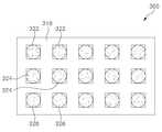
- FIG 3is a schematic plan view of a light emitting device according to an embodiment of the present disclosure.
- FIG. 4is a schematic cross-sectional view for describing a light emitting unit according to an embodiment of the present disclosure.
- FIG. 5is a schematic cross-sectional view for describing a light emitting unit according to another embodiment of the present disclosure.
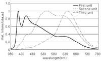
- FIG. 6is a graph showing spectral power distribution of various light emitting units according to an embodiment of the present disclosure.
- FIG. 7is a schematic color coordinate diagram for describing a light emitting device according to an embodiment of the present disclosure.
- FIG. 8is a schematic plan view for describing a light emitting unit according to another embodiment of the present disclosure.
- FIG. 9is a schematic color coordinate diagram for describing a light emitting device according to the embodiment of FIG. 8.
- FIG. 10is a schematic color coordinate diagram for describing a light emitting device according to another embodiment of the present disclosure.
- FIG. 11is a schematic color coordinate diagram for describing a light emitting device according to another embodiment of the present disclosure.
- FIG. 12is a schematic plan view of a light emitting device according to another embodiment of the present disclosure.
- FIG. 13is a schematic plan view of a light emitting device according to still another embodiment of the present disclosure.
- FIG. 14is a schematic plan view of a light emitting device according to another embodiment of the present disclosure.
- 15is a schematic color coordinate diagram for describing a light emitting device according to another embodiment of the present disclosure.
- 16is a graph for explaining spectral power distribution of light emitting devices according to an example of the present disclosure.
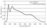
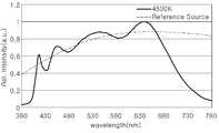
- 17 to 28are graphs showing various spectrums implemented using the light emitting elements of FIG. 16 and the spectrum of blackbody radiation (reference light source) at a corresponding correlated color temperature.
- a light emitting deviceincludes: at least one first light emitting unit including an ultraviolet or purple light emitting diode chip and a first wavelength converter; At least one second light emitting unit comprising an ultraviolet or purple light emitting diode chip and a second wavelength converter; And at least one third light emitting unit including an ultraviolet or purple light emitting diode chip and a third wavelength converter, a triangular area defined by color coordinates of the first light emitting unit, the second light emitting unit and the third light emitting unit. Includes at least some sections on the flankian locus, wherein the highest color temperature on the flankian locus included in the triangle is 5000K or more, and the lowest color temperature is 3000K or less.
- Planckian locus and specific color coordinatesrefer to the Planckian locus and color coordinates in the CIE-1931 coordinate system defined by the American National Standards Institute (ANSI), unless otherwise specified.
- the CIE-1931 coordinate systemcan be easily changed to the 1976 coordinate system by simple formula conversion.
- the lens or the retinait is possible to prevent the lens or the retina from being damaged by light of a blue wavelength by using an ultraviolet or purple light emitting diode chip without using a blue light emitting diode chip. Furthermore, it is possible to provide a light emitting device capable of realizing a color temperature in the range of 3000K to 5000K on the Plankian Locus, and changing the spectral power distribution to correspond to the change in the spectral power distribution of sunlight.
- the highest color temperaturemay be 6000K or more and the lowest color temperature may be 2700K or less. Furthermore, the highest color temperature may be 6500K or more. Moreover, the highest color temperature may be 10000K or more, and the lowest color temperature may be 1800K or less.
- the color coordinate of the second light emitting unitis located above the flankian locus on the CIE-1931 coordinate system, the color coordinate of the first light emitting unit is closer to the color temperature 5000K than the second and third light emitting units, and the third light emitting unit The color coordinate of may be closer to the color temperature 3000K than the first and second light emitting units.
- the first to third light emitting unitsmay be configured to operate in a dimming manner to continuously implement color temperatures on the flankian locus included in the triangle.
- the light emitting devicemay include a plurality of first light emitting units, a plurality of second light emitting units, and a plurality of third light emitting units.
- the light output of the light emitting devicecan be increased by adopting a plurality of light emitting units.
- the light emitting devicemay further include a base, and the first light emitting units, the second light emitting units, and the third light emitting units may be regularly arranged on the base.
- the first light emitting units, the second light emitting units and the third light emitting unitsmay be arranged in one column or in a matrix.
- first light emitting unit, the second light emitting unit and the third light emitting unitform one unit, and the first to third light emitting units in one unit may be arranged to form a triangle.
- first to third light emitting unitsmay be arranged such that units adjacent to one unit forming a triangle form an inverted triangle.
- a distance between adjacent first light emitting units, a distance between adjacent second light emitting units, and a distance between adjacent third light emitting unitsmay be the same.
- the light emitting devicemay further include at least one fourth light emitting unit including an ultraviolet or purple light emitting diode chip and a fourth wavelength converter, and the color coordinates of the fourth light emitting unit are located near the color coordinates of the third light emitting unit. can do.
- at least one fourth light emitting unitincluding an ultraviolet or purple light emitting diode chip and a fourth wavelength converter, and the color coordinates of the fourth light emitting unit are located near the color coordinates of the third light emitting unit. can do.
- the color coordinates of the third light emitting unitmay be located above the Planckian locus on the CIE-1931 coordinate system, and the color coordinates of the fourth light emitting unit may be located below the Planckian locus on the CIE-1931 coordinate system.
- a lighting deviceincludes a light emitting device, wherein the light emitting device includes at least one first light emitting unit including an ultraviolet or purple light emitting diode chip and a first wavelength converter; At least one second light emitting unit comprising an ultraviolet or purple light emitting diode chip and a second wavelength converter; And at least one third light emitting unit including an ultraviolet or purple light emitting diode chip and a third wavelength converter, a triangular area defined by color coordinates of the first light emitting unit, the second light emitting unit and the third light emitting unit. Includes at least some sections on the flankian locus, wherein the highest color temperature on the flankian locus included in the triangle is 5000K or more, and the lowest color temperature is 3000K or less.
- the highest color temperaturemay be 6500K or more, and the lowest color temperature may be 2700K or less.
- the light emitting devicemay further include a base, and the first to third light emitting units may be regularly arranged on the base.
- the first to third light emitting unitsmay be configured to be driven in a dimming manner.
- the light emitting devicemay further include at least one fourth light emitting unit including an ultraviolet or purple light emitting diode chip and a fourth wavelength converter, wherein the color coordinate of the fourth light emitting unit is near the color coordinate of the third light emitting unit. Can be located.
- at least one fourth light emitting unitincluding an ultraviolet or purple light emitting diode chip and a fourth wavelength converter, wherein the color coordinate of the fourth light emitting unit is near the color coordinate of the third light emitting unit. Can be located.
- the color coordinates of the third light emitting unitmay be located above the Planckian Locus on the CIE-1931 coordinate system, and the color coordinates of the fourth light emitting unit may be located below the Planckian locus on the CIE-1931 coordinate system.
- FIG. 3is a schematic plan view of a light emitting device according to an embodiment of the present invention
- FIG. 4is a schematic cross-sectional view of a light emitting unit according to an embodiment of the present disclosure.
- the light emitting device 100includes a base 110, a first light emitting unit 122, a second light emitting unit 124, and a third light emitting unit 126.
- the base 110may include circuit wiring for supplying power to each light emitting unit 122, 124, 126 like a printed circuit board. Also, an integrated circuit device or the like may be mounted on the base 110.
- the first to third light emitting units 122, 124, and 126may be arranged on the base 110.
- a plurality of first light emitting units 122, a plurality of second light emitting units 124, and a plurality of third light emitting units 126may be arranged on the base 110.
- the first to third light emitting units 122, 124, and 126may be arranged as one unit to repeat within one column.
- three different types of light emitting units 122, 124, and 126are described as being arranged on the base 110, but are not necessarily limited to three types of light emitting units, and two types B or four or more types of light emitting units may be arranged.
- the first to third light emitting units 122, 124, and 126may have a similar structure, except that the first to third light emitting units 122, 124, and 126 each have a specific color temperature on the Planckian locus, respectively. Emits light corresponding to. First, the structure of the light emitting unit will be described with reference to FIG. 4.
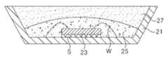
- each light emitting unit 122, 124, and 126includes a light emitting diode chip 23 and a wavelength converter 25, and may include a housing 21 and a molding unit 25.
- the housing 21has leads for electrical connection and may have a cavity.
- the light emitting diode chip 23can be mounted in the cavity of the housing 21 and is electrically connected to the leads.
- the light emitting diode chip 23can be generally a horizontal light emitting diode chip, and thus can be electrically connected to the leads by bonding wires.
- the light emitting diode chip 23emits light having a shorter wavelength than the blue light emitting diode chip.
- the light emitting diode chip 23may be a purple chip or an ultraviolet chip.
- the light emitting diode chip 23may emit light having a peak wavelength in the range of 300 to 440 nm, specifically in the range of 380 to 440 nm, and more specifically in the range of 400 to 420 nm.
- the first to third light emitting units 122, 124, and 126may all include the same type of light emitting diode chips 23 that emit light of the same peak wavelength, but are not limited thereto, and within the above range It may also include light emitting diode chips that emit light of different peak wavelengths. However, all of the first to third light emitting units 122, 124, and 126 emit light of a shorter wavelength than the blue light emitting diode chip, and thus, the first to third light emitting units 122, 124, 126 The light emitted using the light in the blue region has a weaker intensity than the conventional light emitting source.
- the wavelength converter 25may be disposed in the cavity of the housing 21 to cover the light emitting diode chip 23.
- the wavelength converter 25converts light emitted from the light emitting diode chip 23 into light having a longer wavelength.
- the wavelength converter 25may include one or more types of phosphors.
- a light emitting unit that emits light having a desired color temperature using the light emitting diode chip 23 and the wavelength converter 25may be provided.
- the wavelength converter 25may include, for example, a blue phosphor, a green phosphor, a yellow phosphor, or a red phosphor.
- blue phosphorsinclude BAM-based, Halo-Phosphate-based or aluminate-based phosphors, for example, BaMgAl 10 O 17 : Mn 2 + , BaMgAl 12 O 19 : Mn 2+ or (Sr, Ca, Ba) PO 4 Cl: Eu may include a 2 +.
- the blue phosphormay have a peak wavelength in the range of 440 to 500 nm, for example.
- green or yellow phosphorsexamples include LuAG (Lu 3 (Al, Gd) 5 O 12 : Ce 3 + ), YAG (Y 3 (Al, Gd) 5 O 12 : Ce 3+ ), Ga-LuAG ((Lu, Ga) 3 (Al, Gd) 5 O 12 : Ce 3 + ), Ga-YAG ((Ga, Y) 3 (Al, Gd) 5 O 12 : Ce 3+ ), LuYAG ((Lu, Y) 3 ( Al, Gd) 5 O 12 : Ce 3 + ), Ortho-Silicate ((Sr, Ba, Ca, Mg) 2 SiO 4 : Eu 2+ ), Oxynitride ((Ba, Sr, Ca) Si 2 O 2 N 2 : there may be mentioned the Eu 2+): Eu 2 +) , or Thio Gallate (SrGa 2 s 4.
- the green or yellow phosphormay have a peak wavelength in the range of 500 to 600 nm.
- red phosphorexamples include Nitride, Sulfide, Fluoride, or Oxynitride-based phosphor, and specifically, CASN (CaAlSiN 3 : Eu 2 + ), (Ba, Sr, Ca) 2 Si 5 N 8 : Eu 2 + , (Ca, Sr) s 2: and the like Eu 2 +: Eu 2+), or (Sr, Ca) 2 SiS 4 .
- the red phosphormay have a peak wavelength in the range of 600 to 700 nm,
- the molding part 27is formed in the cavity of the housing 21 to cover the wavelength converter 25.
- the molding portion 27is formed of a material transparent to light.
- the molding portion 27may be formed of methyl-based silicon or phenyl-based silicon, and furthermore, may be formed of phenyl-based silicon.
- Phenyl-based siliconeis susceptible to yellowing by ultraviolet light, but has higher strength than methyl-based silicone.
- the molding portion 27is illustrated to be formed to cover the wavelength converter 25, the molding portion 27 and the wavelength converter 25 may be integrally formed. That is, the wavelength converter 25 may include a molding part together with the phosphor, and thus the molding part covering the wavelength converter may be omitted.
- the light emitting diode chip 23is described as being horizontal and electrically connected to the leads using bonding wires, the light emitting diode chip 23 is not limited to the horizontal type, but is vertical or It may be a flip-chip type light emitting diode chip.
- the vertical or flip-chip type light emitting diode chipmay be mounted and used in the cavity of the housing 21.
- the flip-chip type light emitting diode chipmay be directly mounted on the base 110 without the housing 21.
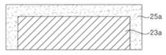
- 5shows a light emitting unit including a flip chip type light emitting diode chip 23a.
- the wavelength converter 25amay cover the top and side surfaces of the light emitting diode chip 23a. Bonding pads are formed on the lower surface of the light emitting diode chip 23a, and thus, the light emitting diode chip 23a on which the wavelength converter 25a is formed can be directly mounted on the base 110 using bonding pads.
- the first to third light emitting units 122, 124, and 126respectively emit light corresponding to the color temperature on the flankian locus, which will be described in detail with reference to FIG. 6.
- 6is a graph showing spectral power distribution of various light emitting units according to an embodiment of the present disclosure.
- Each light emitting unitincludes a light emitting diode chip having a shorter wavelength than a blue light emitting diode chip and a wavelength converter, and has an average color rendering index of 95 or more.
- the light emitting diode chipmay have a peak wavelength of about 416 nm, for example, and phosphors are suitably selected to realize a correlation color temperature of each light emitting unit and an average color rendering index of 95 or more.
- the intensity of the blue wavelength regionincreases as the color temperature increases from 2700K to 6500K.
- the blue wavelength regionsince light in the blue wavelength region is emitted from the blue phosphor, it does not exhibit an abnormally high intensity at a specific wavelength. Also, the intensity of light emitted from the phosphor is higher than that of light emitted from the light emitting diode chip.
- the intensity of the blue regioncan be lowered by using the light emitting units according to the present embodiment compared to the light emitting unit using the conventional blue light emitting diode chip.
- a fidelity index(Rf) calculated by IES TM-30-15.
- Table 1shows the average color rendering index (CRI) and fidelity index according to the correlation color temperatures of the light sources based on the blue light emitting diode chip
- Table 2shows the average color rendering index and fidelity according to the correlation color temperatures of the light emitting units according to the present embodiment. Index.
- a blue light emitting diode chip-based conventional light sourceexhibits a relatively low fidelity index even if it satisfies CRI 95 or higher.
- the difference between the CRI and the fidelity indexis not large, but in the region where the correlation color temperature is high, the difference between the CRI and the fidelity index is large.
- the difference between the CRI and the fidelity index of the light emitting units of this embodiment based on the purple light emitting diode chipis not large. Therefore, by using a light source based on a purple light emitting diode chip, light that is more similar to the actual spectrum of sunlight can be emitted.
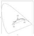
- FIG. 7is a schematic color coordinate diagram for describing a light emitting device according to an embodiment of the present disclosure.
- a light emitting device using the first to third light emitting units 122, 124, and 126will be described.
- the first to third light emitting units 122, 124, and 126may have color temperatures of 6500K, 4000K, and 2700K, respectively. These light emitting units 122, 124, 126 may be arranged on the base 110, as described with reference to FIG.
- 2700K of light emitting units 126are operated to implement light corresponding to sunlight in the morning or evening
- 6500K of light emitting units 122are operated to implement light corresponding to daylight in the middle of the day.
- 4000K of light emitting units 124may be operated to realize light corresponding to sunlight in the middle of the morning and midday or midday and evening. That is, the color temperature of the light source may be changed in accordance with the spectral change of the sunlight in one day cycle by operating the required light-emitting units among the first to third light-emitting units 122, 124, and 126 according to the required color temperature.
- first to third light emitting units 122, 124, and 126are described as having color temperatures of 6500K, 4000K, and 2700K, respectively, the present invention is not limited thereto, and may have different color temperatures. However, these light emitting units 122, 124, and 126 are located on or near the flank of the Frankian locus.
- a specific light emitting unit among the first to third light emitting units 122, 124, and 126may operate. Accordingly, the second and third light emitting units 124 and 126 remain off while the first light emitting unit 122 is operating, and while the second light emitting unit 124 is operating, the first and first The three light emitting units 122 and 126 remain off, and the first and second light emitting units 122 and 124 remain off while the third light emitting unit 126 is operating.
- the present disclosureis not limited to this.
- the first light emitting unit 122 and the second light emitting unit 124may be driven in a dimming manner to realize a correlated color temperature between 6500K and 4000K, and to implement a correlated color temperature between 4000K and 2700K.
- the second light emitting unit 124 and the third light emitting unit 126may be driven in a dimming manner. Accordingly, the first to third light emitting units 122, 124, and 126 may be combined to implement light corresponding to most correlated color temperatures between 6500K and 2700K.
- FIG. 8is a schematic plan view for explaining a light emitting device 200 according to another embodiment of the present disclosure
- FIG. 9shows a schematic color coordinate for explaining a light emitting device according to the embodiment of FIG. 8.
- the light emitting device 200is similar to the light emitting device 100 of FIG. 3, but two types of light emitting units 222 and 224 having different color temperatures are arranged. There is a difference. That is, the first light emitting units 222 and the second light emitting units 224 are arranged on the base 210. The first light emitting units 222 and the second light emitting units 224 may be alternately arranged.
- the base 210is the same as the base 110 described above, detailed description is omitted.
- the structures of the first light emitting units 222 and the second light emitting units 224are similar to those described with reference to FIGS. 4 or 5, detailed descriptions thereof will be omitted.
- the first light emitting unit 222may have a color temperature of 6500K, for example, and the second light emitting unit 224 may have a color temperature of 2700K, for example.
- Light emission units 222 and 224 having color temperatures of 6500K and 2700Kmay be used to implement light corresponding to the spectrum of sunlight at midday and light corresponding to the spectrum of sunlight at morning or evening.
- first light emitting unit 222 of 6500K and the second light emitting unit 224 of 2700Kin a dimming manner, light having different correlation color temperatures between 6500K and 2700K can be realized.
- 6500K first light emitting units 222 and 2700K second light emitting units 224may be mixed and operated to realize light having a color temperature of 4000K.
- the light emitting device according to this embodimentincludes three types of light emitting units, that is, first to third light emitting units 322, 324, and 326, and these light emitting units include a base 110 as described with reference to FIG. ).
- each of the light emitting units 322, 324, and 326includes an ultraviolet chip or a purple chip, and includes a wavelength converter for converting wavelengths of light emitted from the light emitting diode chip.
- the color coordinates of the light emitting units 322, 324, and 326 of this embodimentare different from those described with reference to FIG. 7, and these color coordinates are set using a light emitting diode chip and a wavelength converter.
- a characteristic configuration of the light emitting device of this embodimentwill be described in detail.
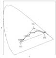
- the first light emitting unit 322, the second light emitting unit 324, and the third light emitting unit 326are arranged to realize a color temperature of 3000K to 5000K on the Frankian locus. Unlike the embodiment of FIG. 7, the first to third light emitting units 322, 324, 326 need not represent color coordinates on the Planckian locus.
- the first light emitting unit 322has color coordinates closer to a color temperature of 5000K than the second and third light emitting units 324 and 326, and the third light emitting unit 326 has first and second light emitting units 322, 324), it may have a color coordinate closer to the color temperature 3000K.
- the first light emitting unit 322may have a color temperature of 5000K
- the third light emitting unit 326may have a color temperature of 3000K.
- the second light emitting unit 324has a color coordinate located above the Planckian Locus curve on the CIE-1931 color coordinate system.
- the x-coordinate of the second light emitting unit 324may be within the range of x-coordinates between the color temperature 5000K and the color temperature 3000K on the Planckian locus.
- a straight line connecting the color coordinates of the first light emitting unit 322 and the color coordinates of the second light emitting unit 324a straight line connecting the color coordinates of the second light emitting unit 324 and the color coordinates of the third light emitting unit 326, and none of the straight lines connecting the color coordinates of the first light emitting unit 322 and the color coordinates of the third light emitting unit 326 traverse the region between 5000K and 3000K on the Planckian locus.
- a triangular areais defined by the color coordinates of the first to third light emitting units 322, 324, and 326, and a curved portion between the color temperature 5000K and the color temperature 3000K on the Plankian locus is disposed in the triangular area.
- a straight line connecting the color coordinates of the first light emitting unit 322 and the color coordinates of the second light emitting unit 324may pass a color temperature of 5000K
- a straight line connecting the color coordinates of the unit 326may pass the color temperature 3000K.
- a straight line connecting the color coordinates of the first light emitting unit 322 and the color coordinates of the third light emitting unit 326may pass a color temperature of 5000K or a color temperature of 3000K.
- the first to third light emitting units 322, 324, and 326are driven in a dimming manner to realize all color temperatures on the Plankian locus within a color temperature range of 3000K to 5000K. Moreover, since none of the first to third light emitting units 322, 324, and 326 include a blue light emitting diode chip, it is possible to prevent the emission of abnormally high intensity light from the blue region.
- the maximum color temperature CTmax implemented according to the present exemplary embodimentmay be 5000K or more according to the selection of the first light emitting unit 322 and the second light emitting unit 324, and the lowest color temperature CTmin is the second light emitting.
- the unit 324 and the third light emitting unit 326may be 3000K or less.
- the color temperatures 3000K and 5000Kare minimum requirements for responding to spectral changes in light during the day, and in this range, light corresponding to spectral changes in sunlight can be similarly emitted.
- the highest color temperature CTmaxmay be further increased, and the lowest color temperature CTmin may be further reduced.
- the highest color temperature (CTmax)may be 6000K or more, 6500K or more, and even 10000K or more.
- the minimum color temperature (CTmin)may be 2700K or less, furthermore, 1800K or less.
- the first light emitting unit 322has an x coordinate value equal to or less than the x coordinate of the color coordinate corresponding to the highest color temperature CTmax in the color temperature range to be implemented
- the second light emitting unit 324is the color temperature range to be implemented
- the third light emitting unit 326has an x coordinate value equal to or greater than the x coordinate of the color coordinate corresponding to the lowest color temperature CTmin in the color temperature range to be implemented.
- FIG. 11shows color coordinates of one embodiment capable of realizing a color temperature on a Plankian locus in a range of 1800K to 10000K.
- the first light emitting unit 322has an x coordinate value equal to or greater than the x coordinate of a color temperature of 10000K
- the second light emitting unit 322has an x coordinate value between 1800K and 10000K
- the third light emitting unit 326Has an x-coordinate value equal to or greater than the x-coordinate of the color temperature of 1800K.
- the y coordinate of the second light emitting unit 324is set such that the color coordinates of the second light emitting unit 324 are located above the flankian locus.
- the y-coordinate values of the first light emitting unit 322 and the third light emitting unit 326are triangles defined by color coordinates of the first to third light emitting units 322, 324, 326 between 0 and 1
- the regionis set to contain a Plankian Locus between 1800K and 10000K color temperature.
- the color temperatures on the Planckian locuscan be implemented by operating the first to third light emitting units 322, 324, 326 in a dimming manner. Accordingly, all color temperatures within the range of the lowest color temperature CTmin to the maximum color temperature CTmax can be implemented. The color temperatures other than the highest color temperature CTmax and the lowest color temperature CTmin are implemented by operating all three types of light emitting units 322, 324, and 326.
- the maximum color temperature CTmaxis a combination of the first light emitting unit 322, the first light emitting unit 322 and the second light emitting unit 324, and the combination of the first light emitting unit 322 and the third light emitting unit 326.
- the lowest color temperature CTminis the third light emitting unit 326, the second light emitting unit 324, and the third. It may be implemented through a combination of the light emitting unit 326, a combination of the first light emitting unit 322 and the third light emitting unit 326, or a combination of the first to third light emitting units (322, 324, 326). .
- most color temperaturesare implemented by operating all three types of light emitting units 322, 324, and 326 in a dimming manner. In the light emitting device described with reference to FIG. 7, some light emitting units stand by in a state of being stopped in order to realize a specific color temperature. However, in this embodiment, all the light emitting units can be driven together, and accordingly, the number of light emitting units required for the lighting fixture can be reduced.
- the first to third light emitting units 322, 324, and 326may be arranged to repeat within a single column on the base, as described with reference to FIG. 3, but are not limited thereto, and may be arranged in various ways.
- Can be. 12 to 14show light emitting devices 300, 400 and 500 in which the first to third light emitting units 322, 324, and 326 are arranged on the base 310 in various ways.
- the base 310is similar to the base 110 described with reference to FIG. 3, detailed description thereof will be omitted.
- the first to third light emitting units 322, 324, and 326may be arranged in a matrix.
- the first light emitting units 322are arranged in one row
- the second light emitting units 324are arranged in the next row
- the third light emitting units 326are arranged in the next row. You can.
- the first to third light emitting units 322, 324, and 326may be disposed together in the same column.
- the first light emitting unit 322, the second light emitting unit 324, and the third light emitting unit 326are arranged in a triangle as one unit, and these units may be arranged to be repeated identically.
- a light emitting device 400capable of emitting more uniform light than the light emitting device 300 of FIG. 12 may be provided.
- the first light emitting unit 322, the second light emitting unit 324, and the third light emitting unit 326are arranged in a triangle as one unit, and these units are repeatedly arranged. Show how. That is, units neighboring one unit arranged in a triangle have an inverted triangle shape. In particular, the distance between the same light emitting units may be constant. For example, the distance between the first light emitting units 322, the distance between the second light emitting units 324 and the distance between the third light emitting units 326 may be the same. Accordingly, the light emitting device 500 may emit light more uniformly than the light emitting device 400.
- 15is a schematic color coordinate diagram for describing a light emitting device according to another embodiment of the present disclosure.
- the light emitting deviceincludes first to fourth light emitting units 422, 424, 426, and 428.
- the first to fourth light emitting units 422, 424, 426, and 428all include an ultraviolet or purple light emitting diode chip and a wavelength converter.
- a rectangular areais defined by color coordinates of the first to fourth light emitting units 422, 424, 426, and 428, and the required Plankian locus is located in the rectangular area. Accordingly, it is possible to implement all of the color temperatures on the Planckian locus located in the square through the combination of the first to fourth light emitting units 422, 424, 426, and 428.
- the first light emitting unit 422has a color coordinate near the color temperature of 10000K
- the second light emitting unit 424may have a color coordinate located above the flankian locus on the CIE-1931 coordinate system.
- the third light emitting unit 426 and the fourth light emitting unit 428may be located near the color temperature of 1800K
- the third light emitting unit 426is located above the flankian locus
- the fourth light emitting unit 428is Can be located below the Plankian Locus.
- a light emitting devicecapable of realizing a color temperature of 1800K to 10000K of a color temperature may be provided.
- the present disclosureis not limited thereto, and the first to fourth light emitting units 422, 424, 426, and 428 may be set to implement, for example, a color temperature range of 3000K to 5000K or more.
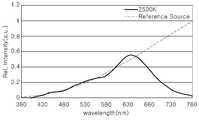
- FIG. 16is a graph for describing spectral power distribution of the first to third light emitting units according to an example of the present disclosure
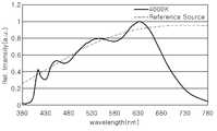
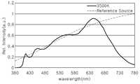
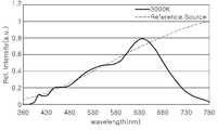
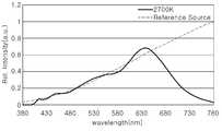
- FIGS. 17 to 28are various spectrums implemented using the light emitting units of FIG. 16 and corresponding thereto These graphs show contrast of the spectrum of blackbody radiation (reference light source) at the correlated color temperature.
- the first to third light emitting unitsall include a purple light emitting diode chip having a peak wavelength of about 416 nm.
- the first light emitting unitincludes a blue phosphor, a green phosphor, a yellow phosphor and a red phosphor, the color coordinates (x, y) are (0.2638, 0.2756), the correlated color temperature is 13597K, and the Duv is 0.0043.
- the second light emitting unitincludes a blue phosphor, a green and yellow phosphor, and a red phosphor, and the color coordinates (x, y) are (0.3860, 0.4354), the correlated color temperature is 4222K, and Duv is 0.0236.
- the third light emitting unitincludes a blue phosphor, a green and yellow phosphor, and a red phosphor, the color coordinates (x, y) are (0.5439, 0.4055), the correlated color temperature is 1822K, and the Duv is 0.000.
- various color temperatures ranging from 1800K to 10000K in color temperaturemay be realized.
- 17 to 18show spectrums at various color temperatures implemented by using the first to third light emitting units in comparison with a reference light source.
- the spectrums at various color temperatures implemented by the first to third light emitting unitsgenerally match the spectrums due to black body radiation in the visible region.
- the intensity of light in the blue regionis not abnormally higher than that of other regions.
- Table 2shows average color rendering index (CRI) and fidelity index (Rf) at various color temperatures implemented using the first to third light emitting units.
- CRI and Rf of the light emitting deviceaccording to an example CCT CRI Rf 10000K 96.2 96.9 6500K 97.6 98.1 5700K 98.3 98.3 5000K 97.3 98.2 4500K 97.4 97.5 4000K 97.4 97.4 3500K 95.6 96.8 3000K 95.6 96.4 2700K 95.2 95.9 2500K 95.6 94.8 2200K 95.0 94.6 1800K 94.3 91.8
- the driving voltage of each light emitting unitwas fixed at 3V and the power consumption was fixed at 27W.
- each light emitting unitis 90 Used individually.
- 90 first light emitting units 122operate to realize a color temperature of 6500K
- 90 second light emitting units 122operate to implement a color temperature of 4000K
- a color temperature of 2700KTo implement, 90 third light emitting units 126 operate.
- one type of light emitting uniteg 122
- other light emitting unitseg, 124 and 126) remain in standby.
- each of the light emitting unitsmay be used, for example, 60. Accordingly, light having a desired color temperature may be realized using a total of 180 light emitting units.
- the first light emitting units 322 or the third light emitting unit 326may be used in increments of 90. have. Even in this case, only 60 second light emitting units 324 may be used, thereby reducing the number of light emitting units required compared to the switching on / off driving method of FIG. 6.
Landscapes
- Engineering & Computer Science (AREA)
- Microelectronics & Electronic Packaging (AREA)
- Physics & Mathematics (AREA)
- Power Engineering (AREA)
- Condensed Matter Physics & Semiconductors (AREA)
- General Physics & Mathematics (AREA)
- Computer Hardware Design (AREA)
- General Engineering & Computer Science (AREA)
- Optics & Photonics (AREA)
- Spectroscopy & Molecular Physics (AREA)
- Led Device Packages (AREA)
Abstract
Description
Translated fromKorean본 개시는 발광 장치에 관한 것으로, 더욱 상세하게는, 발광 다이오드를 광원으로 이용하여 조명 기구에 사용할 수 있는 발광 장치에 관한 것이다.The present disclosure relates to a light emitting device, and more particularly, to a light emitting device that can be used in a lighting device using a light emitting diode as a light source.
대부분의 생명체는 태양광의 변화에 맞추어 활동하도록 적응되어 왔다. 인간의 몸 또한 오랜 기간 태양광에 적응되어 왔다. 이에 따라, 인간의 하루 주기 생체리듬(Circadian Rhythm)이 태양광의 변화에 따라 변한다. 특히, 아침에는 밝은 태양광 하에서 인체에 코르티졸(cortisol) 호르몬이 분비된다. 코르티졸 호르몬은 스트레스와 같은 외부 자극에 대항하도록 신체 각 기관으로 더 많은 혈액을 공급하도록 하며, 이에 따라, 맥박과 호흡이 증가되어 인체가 잠에서 깨어나 외부 활동을 준비하도록 한다. 낮 시간에는 강한 태양광 아래에서 신체 활동을 하다가 저녁이 되면 멜라토닌 호르몬이 분비되어 맥박, 체온, 혈압을 저하시키고 이에 따라 몸이 나른해져 잠이 들도록 도와준다.Most life forms have been adapted to act in response to sunlight. The human body has also been adapted to sunlight for a long time. Accordingly, the human daily cycle circadian rhythm changes according to changes in sunlight. In particular, the cortisol hormone is secreted to the human body in bright sunlight in the morning. Cortisol hormones supply more blood to each organ in the body to counteract external stimuli such as stress, thereby increasing the pulse and breathing, allowing the body to wake up and prepare for external activity. During the daytime, during physical activity under strong sunlight, in the evening, the hormone melatonin is released, which lowers the pulse, body temperature, and blood pressure, thereby helping the body to fall asleep.
그러나 현대 사회에서는 대부분의 사람들이 태양광 아래에서 신체활동을 하는 것이 아니라 주로 집이나 사무실 등의 실내에서 활동을 한다. 한낮에도 실내에 머무르는 시간이 태양광 아래에서 신체 활동을 하는 시간보다 더 긴 것이 일반적이다.However, in modern society, most people do not physically work under sunlight, but mainly indoors, such as at home or in the office. It is common for the time to stay indoors in the middle of the day is longer than the time for physical activity under sunlight.
그런데, 실내 조명 장치는 일반적으로 일정한 스펙트럼 파워 분포(spectral power distribution)를 나타내며, 이러한 스펙트럼 파워 분포는 태양광의 스펙트럼 파워 분포와는 많은 차이가 있다. 예를 들어, 청색, 녹색 및 적색 발광 다이오드를 사용하는 발광 장치의 경우, 청색, 녹색 및 적색의 조합에 의해 백색광을 구현할 수는 있지만, 태양광과 같이 가시영역의 넓은 파장에 걸쳐 스펙트럼 파워 분포를 나타내지 못하고 특정 파장에서 피크를 가지는 분포를 나타낸다.However, indoor lighting devices generally exhibit a constant spectral power distribution, and this spectral power distribution has many differences from the spectral power distribution of sunlight. For example, in the case of a light emitting device using blue, green, and red light emitting diodes, white light may be realized by a combination of blue, green, and red, but the spectral power distribution is spread over a wide wavelength of the visible region, such as sunlight. It does not show and shows a distribution with a peak at a specific wavelength.
도 1은 CIE 색좌표 상의 플랭키안 로커스(plankian locus) 상에 위치하는 몇 개의 색 온도들(Color Temperatures)에 대응하는 흑체 복사의 스펙트럼 파워 분포를 나타내며, 도 2는 몇몇 상관 색 온도들(Corelated color temperatures)에 대응하는 종래의 청색 발광 다이오드 칩을 기반으로 한 백색 광원들의 스펙트럼 파워 분포를 나타내는 그래프이다.FIG. 1 shows the spectral power distribution of blackbody radiation corresponding to several Color Temperatures located on a plankian locus on the CIE color coordinate, and FIG. 2 shows several Corelated color temperatures ) Is a graph showing the spectral power distribution of white light sources based on a conventional blue light emitting diode chip.
도 1과 도 2를 참조하면, 태양과 같은 흑체 복사의 스펙트럼은 종래의 백색 광원의 스펙트럼과 유사하게 색 온도가 높을 수록 청색 파장 영역에서 강도가 높다. 그러나, 색 온도가 높아질 수록 백색 광원의 스펙트럼은 흑체 복사의 스펙트럼과 뚜렷한 차이를 나타낸다. 예컨대 6500K의 온도에서, 흑체 복사의 스펙트럼은 청색 영역에서 적색 영역으로 광의 강도가 서서히 감소하는 경향을 보인다. 이에 반해, 도 2에 도시되듯이, 청색 발광 다이오드 칩을 기반으로 한 백색 조명 장치는 색 온도가 높을수록 청색 파장 영역의 광이 다른 가시영역에 비해 상대적으로 매우 강해진다.1 and 2, the spectrum of black body radiation such as the sun is similar to that of a conventional white light source, and the higher the color temperature, the higher the intensity in the blue wavelength region. However, as the color temperature increases, the spectrum of the white light source shows a distinct difference from that of blackbody radiation. For example, at a temperature of 6500K, the spectrum of blackbody radiation tends to gradually decrease the intensity of light from the blue region to the red region. On the other hand, as shown in Figure 2, the white light-emitting device based on the blue light-emitting diode chip, the higher the color temperature, the light in the blue wavelength region becomes relatively strong compared to other visible regions.
태양 스펙트럼에 적응해 온 인간의 수정체는 비정상적으로 강한 청색 파장 영역의 광에 의해 손상될 수 있으며, 이에 따라 시력이 나빠질 수 있다. 또한, 망막 세포가 과도한 청색 영역의 에너지에 노출됨으로써 뇌에 비정상적인 신호가 전달되어 코르티졸과 멜라토닌과 같은 호르몬을 비정상적으로 생성하거나 억제하여 신체의 하루 주기 생체 리듬(Circadian Rhythm)에 부정적 영향을 미칠 수 있다.The human lens, which has been adapted to the solar spectrum, can be damaged by light in an unusually strong blue wavelength region, which can result in poor vision. In addition, abnormal signals are transmitted to the brain by exposing the retinal cells to the energy of the excessive blue region, thereby abnormally generating or suppressing hormones such as cortisol and melatonin, which may negatively affect the body's daily cycle circadian rhythm. .
본 개시는 인간의 수정체나 망막이 비정상적인 청색 영역의 광에 의해 손상되는 것을 방지 또는 완화할 수 있는 발광 장치 및 조명 기구를 제공한다.The present disclosure provides a light emitting device and a lighting device that can prevent or mitigate damage to the human lens or retina by light in an abnormal blue region.
또한, 본 개시는 태양광의 스펙트럼 파워 분포 변화에 상응하도록 스펙트럼 파워 분포를 변화시킬 수 있는 발광 장치 및 조명 기구를 제공한다.In addition, the present disclosure provides a light emitting device and a lighting device capable of changing the spectral power distribution to correspond to the change in the spectral power distribution of sunlight.
본 개시의 일 실시예에 따른 발광 장치는, 자외선 또는 보라색 발광 다이오드 칩 및 제1 파장변환기를 포함하는 적어도 하나의 제1 발광 유닛; 자외선 또는 보라색 발광 다이오드 칩 및 제2 파장변환기를 포함하는 적어도 하나의 제2 발광 유닛; 및 자외선 또는 보라색 발광 다이오드 칩 및 제3 파장변환기를 포함하는 적어도 하나의 제3 발광 유닛을 포함하고, 상기 제1 발광 유닛, 제2 발광 유닛 및 제3 발광 유닛의 색좌표들에 의해 정의되는 삼각형 영역은 적어도 플랭키안 로커스 상의 일부 구간을 포함하되, 상기 삼각형 내에 포함되는 플랭키안 로커스 상의 최고 색온도는 5000K 이상이고, 최저 색온도는 3000K 이하이다.A light emitting device according to an embodiment of the present disclosure includes: at least one first light emitting unit including an ultraviolet or purple light emitting diode chip and a first wavelength converter; At least one second light emitting unit comprising an ultraviolet or purple light emitting diode chip and a second wavelength converter; And at least one third light emitting unit including an ultraviolet or purple light emitting diode chip and a third wavelength converter, a triangular area defined by color coordinates of the first light emitting unit, the second light emitting unit and the third light emitting unit. Includes at least some sections on the flankian locus, wherein the highest color temperature on the flankian locus included in the triangle is 5000K or more, and the lowest color temperature is 3000K or less.
본 개시의 또 다른 실시예에 따른 조명 기구는, 위에서 언급된 발광 장치를 포함한다.A lighting device according to another embodiment of the present disclosure includes the light emitting device mentioned above.
도 1은 CIE 색좌표 상의 플랭키안 로커스(plankian locus) 상에 위치하는 몇 개의 색온도들(Color Temperatures)에 대응하는 흑체 복사의 스펙트럼 파워 분포를 나타내는 그래프이다.1 is a graph showing the spectral power distribution of blackbody radiation corresponding to several color temperatures located on a plankian locus on a CIE color coordinate.
도 2는 몇몇 상관색온도들(Corelated color temperatures)에 대응하는 종래의 청색 발광 다이오드 칩을 기반으로 한 백색 광원들의 스펙트럼 파워 분포를 나타내는 그래프이다.FIG. 2 is a graph showing spectral power distribution of white light sources based on a conventional blue light emitting diode chip corresponding to several related color temperatures.
도 3은 본 개시의 일 실시예에 따른 발광 장치를 설명하기 위한 개략적인 평면도이다.3 is a schematic plan view of a light emitting device according to an embodiment of the present disclosure.
도 4는 본 개시의 일 실시예에 따른 발광 유닛을 설명하기 위한 개략적인 단면도이다.4 is a schematic cross-sectional view for describing a light emitting unit according to an embodiment of the present disclosure.
도 5는 본 개시의 또 다른 실시예에 따른 발광 유닛을 설명하기 위한 개략적인 단면도이다.5 is a schematic cross-sectional view for describing a light emitting unit according to another embodiment of the present disclosure.
도 6은 본 개시의 일 실시예에 따른 다양한 발광 유닛들의 스펙트럼 파워 분포를 나타내는 그래프이다.6 is a graph showing spectral power distribution of various light emitting units according to an embodiment of the present disclosure.
도 7은 본 개시의 일 실시예에 따른 발광 장치를 설명하기 위한 개략적인 색좌표를 나타낸다.7 is a schematic color coordinate diagram for describing a light emitting device according to an embodiment of the present disclosure.
도 8은 본 개시의 또 다른 실시예에 따른 발광 유닛을 설명하기 위한 개략적인 평면도이다..8 is a schematic plan view for describing a light emitting unit according to another embodiment of the present disclosure.
도 9는 도 8의 실시예에 따른 발광 장치를 설명하기 위한 개략적인 색좌표를 나타낸다.9 is a schematic color coordinate diagram for describing a light emitting device according to the embodiment of FIG. 8.
도 10은 본 개시의 또 다른 실시예에 따른 발광 장치를 설명하기 위한 개략적인 색좌표를 나타낸다.10 is a schematic color coordinate diagram for describing a light emitting device according to another embodiment of the present disclosure.
도 11은 본 개시의 또 다른 실시예에 따른 발광 장치를 설명하기 위한 개략적인 색좌표를 나타낸다.11 is a schematic color coordinate diagram for describing a light emitting device according to another embodiment of the present disclosure.
도 12는 본 개시의 또 다른 실시예에 따른 발광 장치를 설명하기 위한 개략적인 평면도이다.12 is a schematic plan view of a light emitting device according to another embodiment of the present disclosure.
도 13은 본 개시의 또 다른 실시예에 따른 발광 장치를 설명하기 위한 개략적인 평면도이다.13 is a schematic plan view of a light emitting device according to still another embodiment of the present disclosure.
도 14는 본 개시의 또 다른 실시예에 따른 발광 장치를 설명하기 위한 개략적인 평면도이다.14 is a schematic plan view of a light emitting device according to another embodiment of the present disclosure.
도 15는 본 개시의 또 다른 실시예에 따른 발광 장치를 설명하기 위한 개략적인 색좌표를 나타낸다.15 is a schematic color coordinate diagram for describing a light emitting device according to another embodiment of the present disclosure.
도 16은 본 개시의 일 예에 따른 발광 소자들의 스펙트럼 파워 분포를 설명하기 위한 그래프이다.16 is a graph for explaining spectral power distribution of light emitting devices according to an example of the present disclosure.
도 17 내지 도 28은 도 16의 발광 소자들을 이용하여 구현되는 다양한 스펙트럼들과 이에 대응하는 상관색온도에서의 흑체 복사(기준 광원)의 스펙트럼을 대비하여 나타낸 그래프들이다.17 to 28 are graphs showing various spectrums implemented using the light emitting elements of FIG. 16 and the spectrum of blackbody radiation (reference light source) at a corresponding correlated color temperature.
이하, 첨부한 도면들을 참조하여 본 발명의 실시예들을 상세히 설명하기로 한다. 다음에 소개되는 실시예들은 당업자에게 본 발명의 사상이 충분히 전달될 수 있도록 하기 위해 예로서 제공되는 것이다. 따라서, 본 발명은 이하 설명되는 실시예들에 한정되지 않고 다른 형태로 구체화될 수도 있다. 그리고, 도면들에 있어서, 구성요소의 폭, 길이, 두께 등은 편의를 위하여 과장되어 표현될 수 있다. 명세서 전체에 걸쳐서 동일한 참조번호들은 동일한 구성요소들을 나타낸다.Hereinafter, embodiments of the present invention will be described in detail with reference to the accompanying drawings. The embodiments introduced below are provided as examples in order to sufficiently convey the spirit of the present invention to those skilled in the art. Accordingly, the present invention is not limited to the embodiments described below and may be embodied in other forms. In addition, in the drawings, the width, length, and thickness of components may be exaggerated for convenience. Throughout the specification, the same reference numbers indicate the same components.
본 개시의 일 실시예에 따른 발광 장치는, 자외선 또는 보라색 발광 다이오드 칩 및 제1 파장변환기를 포함하는 적어도 하나의 제1 발광 유닛; 자외선 또는 보라색 발광 다이오드 칩 및 제2 파장변환기를 포함하는 적어도 하나의 제2 발광 유닛; 및 자외선 또는 보라색 발광 다이오드 칩 및 제3 파장변환기를 포함하는 적어도 하나의 제3 발광 유닛을 포함하고, 상기 제1 발광 유닛, 제2 발광 유닛 및 제3 발광 유닛의 색좌표들에 의해 정의되는 삼각형 영역은 적어도 플랭키안 로커스 상의 일부 구간을 포함하되, 상기 삼각형 내에 포함되는 플랭키안 로커스 상의 최고 색온도는 5000K 이상이고, 최저 색온도는 3000K 이하이다.A light emitting device according to an embodiment of the present disclosure includes: at least one first light emitting unit including an ultraviolet or purple light emitting diode chip and a first wavelength converter; At least one second light emitting unit comprising an ultraviolet or purple light emitting diode chip and a second wavelength converter; And at least one third light emitting unit including an ultraviolet or purple light emitting diode chip and a third wavelength converter, a triangular area defined by color coordinates of the first light emitting unit, the second light emitting unit and the third light emitting unit. Includes at least some sections on the flankian locus, wherein the highest color temperature on the flankian locus included in the triangle is 5000K or more, and the lowest color temperature is 3000K or less.
이하에서, 플랭키안 로커스 및 특정 색좌표는 특별한 언급이 없는 한 미국 표준 협회(American National Standards Institute, ANSI)에 의하여 규정된 CIE-1931 좌표계에서의 플랭키안 로커스 및 색좌표를 의미한다. CIE-1931 좌표계는 간단한 수식 변환에 의해 1976 좌표계로 쉽게 변경될 수 있다.Hereinafter, the Planckian locus and specific color coordinates refer to the Planckian locus and color coordinates in the CIE-1931 coordinate system defined by the American National Standards Institute (ANSI), unless otherwise specified. The CIE-1931 coordinate system can be easily changed to the 1976 coordinate system by simple formula conversion.
본 실시예에 따르면, 청색 발광 다이오드 칩을 사용하지 않고 자외선 또는 보라색 발광 다이오드 칩을 사용함으로써 청색 파장의 광에 의해 수정체나 망막이 손상되는 것을 방지할 수 있다. 나아가, 플랭키안 로커스 상의 3000K 내지 5000K 범위의 색온도를 구현할 수 있어, 태양광의 스펙트럼 파워 분포 변화에 상응하도록 스펙트럼 파워 분포를 변화시킬 수 있는 발광 장치를 제공할 수 있다.According to this embodiment, it is possible to prevent the lens or the retina from being damaged by light of a blue wavelength by using an ultraviolet or purple light emitting diode chip without using a blue light emitting diode chip. Furthermore, it is possible to provide a light emitting device capable of realizing a color temperature in the range of 3000K to 5000K on the Plankian Locus, and changing the spectral power distribution to correspond to the change in the spectral power distribution of sunlight.
상기 최고 색온도를 증가시키고, 최저 색온도를 감소시킴으로써 태양광의 스펙트럼에 더 유사한 광을 구현할 수 있다. 예를 들어, 상기 최고 색온도는 6000K 이상이고 최저 색온도는 2700K 이하일 수 있다. 나아가, 상기 최고 색온도는 6500K 이상일 수 있다. 더욱이, 상기 최고 색온도는 10000K 이상이고, 상기 최저 색온도는 1800K 이하일 수 있다.By increasing the highest color temperature and reducing the lowest color temperature, light more similar to the spectrum of sunlight can be realized. For example, the highest color temperature may be 6000K or more and the lowest color temperature may be 2700K or less. Furthermore, the highest color temperature may be 6500K or more. Moreover, the highest color temperature may be 10000K or more, and the lowest color temperature may be 1800K or less.
한편, 상기 제2 발광 유닛의 색좌표는 CIE-1931 좌표계 상에서 플랭키안 로커스 위쪽에 위치하고, 상기 제1 발광 유닛의 색좌표는 제2 및 제3 발광 유닛들보다 색온도 5000K에 더 가깝고, 상기 제3 발광 유닛의 색좌표는 제1 및 제2 발광 유닛들보다 색온도 3000K에 더 가까울 수 있다.On the other hand, the color coordinate of the second light emitting unit is located above the flankian locus on the CIE-1931 coordinate system, the color coordinate of the first light emitting unit is closer to the
상기 제1 내지 제3 발광 유닛들은 디밍 방식으로 작동하여 상기 삼각형 내에 포함되는 플랭키안 로커스 상의 색온도들을 연속적으로 구현하도록 구성될 수 있다.The first to third light emitting units may be configured to operate in a dimming manner to continuously implement color temperatures on the flankian locus included in the triangle.
몇몇 실시예들에 있어서, 상기 발광 장치는 복수의 제1 발광 유닛들, 복수의 제2 발광 유닛들 및 복수의 제3 발광 유닛들을 포함할 수 있다. 복수의 발광 유닛들을 채택함으로써 발광 장치의 광 출력을 증가시킬 수 있다.In some embodiments, the light emitting device may include a plurality of first light emitting units, a plurality of second light emitting units, and a plurality of third light emitting units. The light output of the light emitting device can be increased by adopting a plurality of light emitting units.
한편, 상기 발광 장치는 베이스를 더 포함할 수 있으며, 상기 제1 발광 유닛들, 제2 발광 유닛들 및 제3 발광 유닛들은 상기 베이스 상에 규칙적으로 배열될 수 있다.Meanwhile, the light emitting device may further include a base, and the first light emitting units, the second light emitting units, and the third light emitting units may be regularly arranged on the base.
일 실시예에 있어서, 상기 제1 발광 유닛들, 제2 발광 유닛들 및 제3 발광 유닛들은 일 열로 또는 행렬로 배열될 수 있다.In one embodiment, the first light emitting units, the second light emitting units and the third light emitting units may be arranged in one column or in a matrix.
다른 실시예에 있어서, 상기 제1 발광 유닛, 제2 발광 유닛 및 제3 발광 유닛이 하나의 단위를 이루며, 하나의 단위 내의 제1 내지 제3 발광 유닛들은 삼각형을 이루도록 배열될 수 있다.In another embodiment, the first light emitting unit, the second light emitting unit and the third light emitting unit form one unit, and the first to third light emitting units in one unit may be arranged to form a triangle.
나아가, 상기 제1 내지 제3 발광 유닛들은 삼각형을 이루는 하나의 단위에 이웃하는 단위는 역삼각형을 이루도록 배열될 수 있다.Furthermore, the first to third light emitting units may be arranged such that units adjacent to one unit forming a triangle form an inverted triangle.
또한, 인접한 제1 발광 유닛들 사이의 거리, 인접한 제2 발광 유닛들 사이의 거리 및 인접한 제3 발광 유닛들 사이의 거리는 동일할 수 있다.Also, a distance between adjacent first light emitting units, a distance between adjacent second light emitting units, and a distance between adjacent third light emitting units may be the same.
상기 발광 장치는 자외선 또는 보라색 발광 다이오드 칩 및 제4 파장변환기를 포함하는 적어도 하나의 제4 발광 유닛을 더 포함할 수 있으며, 상기 제4 발광 유닛의 색좌표는 상기 제3 발광 유닛의 색좌표 근처에 위치할 수 있다.The light emitting device may further include at least one fourth light emitting unit including an ultraviolet or purple light emitting diode chip and a fourth wavelength converter, and the color coordinates of the fourth light emitting unit are located near the color coordinates of the third light emitting unit. can do.
나아가, 상기 제3 발광 유닛의 색좌표는 CIE-1931 좌표계 상에서 플랭키안 로커스 위쪽에 위치하고, 상기 제4 발광 유닛의 색좌표는 CIE-1931 좌표계 상에서 플랭키안 로커스 아래쪽에 위치할 수 있다.Furthermore, the color coordinates of the third light emitting unit may be located above the Planckian locus on the CIE-1931 coordinate system, and the color coordinates of the fourth light emitting unit may be located below the Planckian locus on the CIE-1931 coordinate system.
본 개시의 또 다른 실시예에 따른 조명 기구는 발광 장치를 포함하며, 상기 발광 장치는, 자외선 또는 보라색 발광 다이오드 칩 및 제1 파장변환기를 포함하는 적어도 하나의 제1 발광 유닛; 자외선 또는 보라색 발광 다이오드 칩 및 제2 파장변환기를 포함하는 적어도 하나의 제2 발광 유닛; 및 자외선 또는 보라색 발광 다이오드 칩 및 제3 파장변환기를 포함하는 적어도 하나의 제3 발광 유닛을 포함하고, 상기 제1 발광 유닛, 제2 발광 유닛 및 제3 발광 유닛의 색좌표들에 의해 정의되는 삼각형 영역은 적어도 플랭키안 로커스 상의 일부 구간을 포함하되, 상기 삼각형 내에 포함되는 플랭키안 로커스 상의 최고 색온도는 5000K 이상이고, 최저 색온도는 3000K 이하이다.A lighting device according to another embodiment of the present disclosure includes a light emitting device, wherein the light emitting device includes at least one first light emitting unit including an ultraviolet or purple light emitting diode chip and a first wavelength converter; At least one second light emitting unit comprising an ultraviolet or purple light emitting diode chip and a second wavelength converter; And at least one third light emitting unit including an ultraviolet or purple light emitting diode chip and a third wavelength converter, a triangular area defined by color coordinates of the first light emitting unit, the second light emitting unit and the third light emitting unit. Includes at least some sections on the flankian locus, wherein the highest color temperature on the flankian locus included in the triangle is 5000K or more, and the lowest color temperature is 3000K or less.
상기 최고 색온도를 증가시키고 최저 색온도를 감소시킴에 따라 태양광에 더 가까운 광을 구현할 수 있다. 특정 실시예에 있어서, 상기 최고 색온도는 6500K 이상일 수 있으며, 상기 최저 색온도는 2700K 이하일 수 있다.As the maximum color temperature is increased and the minimum color temperature is decreased, light closer to sunlight can be realized. In a specific embodiment, the highest color temperature may be 6500K or more, and the lowest color temperature may be 2700K or less.
상기 발광 장치는 베이스를 더 포함할 수 있으며, 상기 제1 내지 제3 발광 유닛들은 상기 베이스 상에 규칙적으로 배열될 수 있다.The light emitting device may further include a base, and the first to third light emitting units may be regularly arranged on the base.
한편, 상기 제1 내지 제3 발광 유닛들은 디밍 방식으로 구동되도록 구성될 수 있다.Meanwhile, the first to third light emitting units may be configured to be driven in a dimming manner.
상기 발광 장치는, 자외선 또는 보라색 발광 다이오드 칩 및 제4 파장변환기를 포함하는 적어도 하나의 제4 발광 유닛을 더 포함할 수 있으며, 상기 제4 발광 유닛의 색좌표는 상기 제3 발광 유닛의 색좌표 근처에 위치할 수 있다.The light emitting device may further include at least one fourth light emitting unit including an ultraviolet or purple light emitting diode chip and a fourth wavelength converter, wherein the color coordinate of the fourth light emitting unit is near the color coordinate of the third light emitting unit. Can be located.
나아가, 상기 제3 발광 유닛의 색좌표는 CIE-1931 좌표계 상에서 플랭키안 로커스 위쪽에 위치하고, 상기 제4 발광 유닛의 색좌표는 CIE-1931 좌표계 상에서 플랭키안 로커스 아래쪽에 위치할 수 있다.Furthermore, the color coordinates of the third light emitting unit may be located above the Planckian Locus on the CIE-1931 coordinate system, and the color coordinates of the fourth light emitting unit may be located below the Planckian locus on the CIE-1931 coordinate system.
이하, 첨부된 도면을 참조하여 본 개시의 다양한 실시예들에 대해 설명한다.Hereinafter, various embodiments of the present disclosure will be described with reference to the accompanying drawings.
도 3은 본 발명의 일 실시예에 따른 발광 장치를 설명하기 위한 개략적인 평면도이고, 도 4는 본 개시의 일 실시예에 따른 발광 유닛을 설명하기 위한 개략적인 단면도이다.3 is a schematic plan view of a light emitting device according to an embodiment of the present invention, and FIG. 4 is a schematic cross-sectional view of a light emitting unit according to an embodiment of the present disclosure.
도 3을 참조하면, 발광 장치(100)는 베이스(110), 제1 발광 유닛(122), 제2 발광 유닛(124) 및 제3 발광 유닛(126)을 포함한다.Referring to FIG. 3, the
베이스(110)는 인쇄회로보드와 같이 각 발광 유닛(122, 124, 126)에 전력을 공급하기 위한 회로 배선을 포함할 수 있다. 또한, 베이스(110) 상에 집적회로 소자 등이 실장될 수도 있다.The base 110 may include circuit wiring for supplying power to each
제1 내지 제3 발광 유닛들(122, 124, 126)은 베이스(110) 상에 배열될 수 있다. 베이스(110) 상에 복수개의 제1 발광 유닛들(122), 복수개의 제2 발광 유닛들(124) 및 복수개의 제3 발광 유닛들(126)이 배열될 수 있다. 또한, 도 3에 도시한 바와 같이 제1 내지 제3 발광 유닛들(122, 124, 126)이 하나의 단위가 되어 한 열 내에 반복하도록 배치될 수 있다.The first to third
본 실시예에 있어서, 세 종류의 서로 다른 발광 유닛들(122, 124, 126)이 베이스(110) 상에 배열된 것에 대해 설명하지만, 반드시 세 종류의 발광 유닛들에 한정되는 것은 아니며, 2종류나 또는 4 종류 이상의 발광 유닛들이 배열될 수도 있다.In this embodiment, three different types of
제1 내지 제3 발광 유닛들(122, 124, 126)은 유사한 구조를 가질 수 있으며, 다만, 상기 제1 내지 제3 발광 유닛들(122, 124, 126)은 각각 대체로 플랭키안 로커스 상의 특정 색온도에 대응하는 광을 방출한다. 우선, 발광 유닛의 구조에 대해 도 4를 참조하여 설명한다.The first to third
도 4를 참조하면, 각각의 발광 유닛(122, 124, 126)은 발광 다이오드 칩(23) 및 파장변환기(25)를 포함하며, 하우징(21) 및 몰딩부(25)를 포함할 수 있다.Referring to FIG. 4, each
하우징(21)은 전기적 연결을 위한 리드들을 가지며, 캐비티를 가질 수 있다.The
발광 다이오드 칩(23)은 하우징(21)의 캐비티 내에 실장될 수 있으며, 리드들에 전기적으로 연결된다. 발광 다이오드 칩(23)은 일반적으로 수평형 발광 다이오드 칩일 수 있으며, 따라서, 본딩 와이어들에 의해 리드들에 전기적으로 연결될 수 있다.The light emitting
발광 다이오드 칩(23)은 청색 발광 다이오드 칩에 비해 단파장의 광을 방출한다. 예컨대, 발광 다이오드 칩(23)은 보라색 칩 또는 자외선 칩일 수 있다. 특히, 발광 다이오드 칩(23)은 300 내지 440nm 범위 내, 구체적으로 380 내지 440nm 범위 내, 더 구체적으로 400 내지 420nm 범위 내의 피크 파장을 가지는 광을 방출할 수 있다.The light emitting
제1 내지 제3 발광 유닛들(122, 124, 126)이 모두 동일한 피크 파장의 광을 방출하는 동종의 발광 다이오드 칩(23)을 포함할 수 있으나, 이에 한정되는 것은 아니며, 위 범위 내에서 서로 다른 피크 파장의 광을 방출하는 발광 다이오드 칩들을 포함할 수도 있다. 다만, 제1 내지 제3 발광 유닛들(122, 124, 126)은 모두 청색 발광 다이오드 칩보다 단파장의 광을 방출하며, 따라서, 상기 제1 내지 제3 발광 유닛들(122, 124, 126)을 이용하여 방출되는 광은 청색 영역의 광의 강도가 종래의 발광 광원에 비해 약하다.The first to third
파장변환기(25)는 발광 다이오드 칩(23)을 덮도록 하우징(21)의 캐비티 내에 배치될 수 있다. 파장변환기(25)는 발광 다이오드 칩(23)에서 방출된 광을 그 보다 장파장의 광으로 변환한다.The
파장변환기(25)는 한 종류 이상의 형광체를 포함할 수 있다. 발광 다이오드 칩(23)과 파장변환기(25)를 이용하여 원하는 색온도의 광을 방출하는 발광 유닛이제공될 수 있다.The
파장변환기(25)는 예를 들어 청색 형광체, 녹색 형광체, 황색 형광체 또는 적색 형광체를 포함할 수 있다. 청색 형광체의 예로는 BAM계, Halo-Phosphate계 또는 알루미네이트계의 형광체를 들 수 있으며, 예를 들어, BaMgAl10O17:Mn2+, BaMgAl12O19:Mn2+ 또는 (Sr,Ca,Ba)PO4Cl:Eu2+ 를 포함할 수 있다. 청색 형광체는 예를 들어 440 내지 500nm 범위 내에 피크 파장을 가질 수 있다.The
녹색 또는 황색 형광체의 예로는 LuAG(Lu3(Al,Gd)5O12:Ce3+), YAG(Y3(Al,Gd)5O12:Ce3+), Ga-LuAG((Lu,Ga)3(Al,Gd)5O12:Ce3+), Ga-YAG ((Ga,Y)3(Al,Gd)5O12:Ce3+), LuYAG ((Lu,Y)3(Al,Gd)5O12:Ce3+), Ortho-Silicate ((Sr,Ba,Ca,Mg)2SiO4:Eu2+), Oxynitride ((Ba,Sr,Ca)Si2O2N2:Eu2+), 또는 Thio Gallate (SrGa2S4:Eu2+) 를 들 수 있다. 녹색 또는 황색 형광체는 500 내지 600nm 범위 내에 피크 파장을 가질 수 있다.Examples of green or yellow phosphors include LuAG (Lu3 (Al, Gd)5 O12 : Ce3+ ), YAG (Y3 (Al, Gd)5 O12 : Ce3+ ), Ga-LuAG ((Lu, Ga)3 (Al, Gd)5 O12 : Ce3+ ), Ga-YAG ((Ga, Y)3 (Al, Gd)5 O12 : Ce3+ ), LuYAG ((Lu, Y)3 ( Al, Gd)5 O12 : Ce3+ ), Ortho-Silicate ((Sr, Ba, Ca, Mg)2 SiO4 : Eu2+ ), Oxynitride ((Ba, Sr, Ca) Si2 O2 N2 : there may be mentioned theEu 2+): Eu 2 +) , or Thio Gallate (SrGa2 s4. The green or yellow phosphor may have a peak wavelength in the range of 500 to 600 nm.
적색 형광체의 예로는 Nitride, Sulfide, Fluoride 또는 Oxynitride 계의 형광체를 들 수 있고, 구체적으로, CASN (CaAlSiN3:Eu2+), (Ba,Sr,Ca)2Si5N8:Eu2+, (Ca,Sr)S2:Eu2+), 또는 (Sr,Ca)2SiS4:Eu2+ 등을 들 수 있다. 적색 형광체는 600 내지 700nm 범위 내에 피크 파장을 가질 수 있다.,Examples of the red phosphor include Nitride, Sulfide, Fluoride, or Oxynitride-based phosphor, and specifically, CASN (CaAlSiN3 : Eu2+ ), (Ba, Sr, Ca)2 Si5 N8 : Eu2+ , (Ca, Sr) s2: and the like Eu2+: Eu2+), or(Sr, Ca) 2 SiS 4 . The red phosphor may have a peak wavelength in the range of 600 to 700 nm,
몰딩부(27)는 파장변환기(25)를 덮도록 하우징(21)의 캐비티에 형성된다. 몰딩부(27)는 광에 투명한 재료로 형성된다. 특히, 몰딩부(27)는 메틸계 실리콘 또는 페닐계 실리콘으로 형성될 수 있으며, 더욱이, 페닐계 실리콘으로 형성될 수 있다. 페닐계 실리콘은 자외선에 의해 황변이 발생되기 쉽지만, 메틸계 실리콘에 비해 강도가 높다. 특히, 본 실시예에서, 발광 다이오드 칩(23)에서 방출된 광은 파장변환기(25)에 의해 장파장의 광으로 변환되므로, 황변 발생을 걱정할 필요가 없어 페닐계 실리콘을 사용할 수 있다.The
본 실시예에서, 몰딩부(27)가 파장변환기(25)를 덮도록 형성된 것을 예시하였으나, 몰딩부(27)와 파장변환기(25)가 일체로 형성될 수도 있다. 즉, 파장변환기(25)가 형광체와 함께 몰딩부를 포함할 수 있으며, 따라서, 파장변환기를 덮는 몰딩부는 생략될 수 있다.In this embodiment, although the
본 실시예에서, 발광 다이오드 칩(23)이 수평형이고, 본딩 와이어들을 이용하여 리드들에 전기적으로 연결되는 것으로 설명하지만, 발광 다이오드 칩(23)은 수평형에 한정되는 것은 아니며, 수직형 또는 플립칩 타입의 발광 다이오드 칩일 수도 있다. 또한, 상기 수직형 또는 플립칩 타입의 발광 다이오드 칩이 하우징(21)의 캐비티 내에 실장되어 사용될 수도 있다. 나아가, 플립칩 타입의 발광 다이오드 칩은 하우징(21) 없이 직접 베이스(110) 상에 실장될 수도 있다. 도 5는 플립칩 타입의 발광 다이오드 칩(23a)을 포함하는 발광 유닛을 도시한다. 파장변환기(25a)는 발광 다이오드 칩(23a)의 상면 및 측면을 덮을 수 있다. 발광 다이오드 칩(23a)의 하면에 본딩 패드들이 형성되며, 따라서, 파장변환기(25a)가 형성된 발광 다이오드 칩(23a)이 직접 본딩 패드들을 이용하여 베이스(110) 상에 실장될 수 있다.In this embodiment, although the light emitting
한편, 앞서 설명한 바와 같이, 제1 내지 제3 발광 유닛들(122, 124, 126)은 각각 플랭키안 로커스 상의 색온도에 대응하는 광을 방출하며, 이에 대해, 도 6을 참조하여 상세히 설명한다. 도 6은 본 개시의 일 실시예에 따른 다양한 발광 유닛들의 스펙트럼 파워 분포를 나타내는 그래프이다.Meanwhile, as described above, the first to third
도 6을 참조하면, 상관 색 온도 2700K에서 6500K의 발광 유닛들의 스펙트럼 파워 분포가 개시된다. 각각의 발광 유닛들은 청색 발광 다이오드 칩보다 단파장인 발광 다이오드 칩과 파장변환기를 포함하며, 평균 연색 지수는 95 이상이다. 발광 다이오드 칩은 예를 들어 약 416nm의 피크 파장을 가질 수 있으며, 각 발광 유닛의 상관 색 온도 및 95 이상의 평균 연색 지수를 구현하기 위해 형광체들이 적합하게 선택된다.Referring to FIG. 6, a spectral power distribution of light emitting units having a correlation color temperature of 2700K to 6500K is disclosed. Each light emitting unit includes a light emitting diode chip having a shorter wavelength than a blue light emitting diode chip and a wavelength converter, and has an average color rendering index of 95 or more. The light emitting diode chip may have a peak wavelength of about 416 nm, for example, and phosphors are suitably selected to realize a correlation color temperature of each light emitting unit and an average color rendering index of 95 or more.
도 6에 도시되듯이, 2700K에서 6500K로 색온도가 증가함에 따라 청색 파장 영역의 강도가 증가한다. 그러나, 청색 파장 영역의 광은 청색 형광체로부터 방출되므로, 특정 파장에서 비정상적으로 높은 강도를 나타내는 것은 아니다. 또한, 발광 다이오드 칩으로부터 방출된 광의 강도보다 형광체에서 방출된 광의 강도가 더 높다.As shown in FIG. 6, the intensity of the blue wavelength region increases as the color temperature increases from 2700K to 6500K. However, since light in the blue wavelength region is emitted from the blue phosphor, it does not exhibit an abnormally high intensity at a specific wavelength. Also, the intensity of light emitted from the phosphor is higher than that of light emitted from the light emitting diode chip.
이에 따라, 본 실시예에 따른 발광 유닛들을 사용함으로써 종래의 청색 발광 다이오드 칩을 사용하는 발광 유닛에 비해 청색 영역의 강도를 낮출 수 있다.Accordingly, the intensity of the blue region can be lowered by using the light emitting units according to the present embodiment compared to the light emitting unit using the conventional blue light emitting diode chip.
더욱이, 종래 기술에 따른 청색 발광 다이오드 칩 기반의 백색 광원과 본 실시예의 발광 유닛들을 사용한 광원의 스펙트럼 차이는 IES TM-30-15에 의해 계산되는 충실도 지수(fidelity index, Rf)를 통해서 명확하게 확인된다. 표 1은 청색 발광 다이오드 칩 기반의 광원들의 상관색온도들에 따른 평균 연색 지수(CRI) 및 충실도 지수를 나타낸 것이고, 표 2는 본 실시예에 따른 발광 유닛들의 상관 색온도들에 따른 평균 연색 지수와 충실도 지수를 나타낸다.Moreover, the spectral difference between the white light source based on the blue light emitting diode chip according to the prior art and the light source using the light emitting units of this embodiment is clearly confirmed through a fidelity index (Rf) calculated by IES TM-30-15. do. Table 1 shows the average color rendering index (CRI) and fidelity index according to the correlation color temperatures of the light sources based on the blue light emitting diode chip, and Table 2 shows the average color rendering index and fidelity according to the correlation color temperatures of the light emitting units according to the present embodiment. Index.
표 1을 참조하면, 청색 발광 다이오드 칩 기반의 종래의 광원은 CRI 95이상을 충족하더라도 충실도 지수가 상대적으로 낮은 값을 나타낸다. 특히, 상관 색 온도가 낮은 영역에서는 CRI와 충실도 지수의 차이가 크지 않지만, 상관 색 온도가 높은 영역에서는 CRI와 충실도 지수의 차이가 크다.Referring to Table 1, a blue light emitting diode chip-based conventional light source exhibits a relatively low fidelity index even if it satisfies CRI 95 or higher. In particular, in the region where the correlation color temperature is low, the difference between the CRI and the fidelity index is not large, but in the region where the correlation color temperature is high, the difference between the CRI and the fidelity index is large.
이에 반해, 보라색 발광 다이오드 칩 기반의 본 실시예의 발광 유닛들은 CRI와 충실도 지수의 차이가 크지 않은 것을 확인할 수 있다. 따라서, 보라색 발광 다이오드 칩 기반의 광원을 이용함으로써 태양광의 실제 스펙트럼에 더 유사한 광을 방출할 수 있다.On the other hand, it can be confirmed that the difference between the CRI and the fidelity index of the light emitting units of this embodiment based on the purple light emitting diode chip is not large. Therefore, by using a light source based on a purple light emitting diode chip, light that is more similar to the actual spectrum of sunlight can be emitted.
한편, 본 실시예의 발광 유닛들을 하나의 발광 장치 내에 배열함으로써 하나의 발광 장치로 다양한 색온도를 구현할 수 있다.On the other hand, by arranging the light emitting units of the present embodiment in one light emitting device, various color temperatures can be realized with one light emitting device.
도 7은 본 개시의 일 실시예에 따른 발광 장치를 설명하기 위한 개략적인 색좌표를 나타낸다. 여기서는, 도 3에서 설명한 바와 같이, 제1 내지 제3 발광 유닛들(122, 124, 126)을 이용한 발광 장치에 대해 설명한다.7 is a schematic color coordinate diagram for describing a light emitting device according to an embodiment of the present disclosure. Here, as described in FIG. 3, a light emitting device using the first to third
제1 내지 제3 발광 유닛들(122, 124, 126)은 각각 색 온도가 6500K, 4000K 및 2700K일 수 있다. 이들 발광 유닛들(122, 124, 126)은 도 3을 참조하여 설명한 바와 같이, 베이스(110) 상에 배열될 수 있다.The first to third
한편, 아침 또는 저녁의 태양광에 대응하는 광을 구현하기 위해 2700K의 발광 유닛들(126)이 작동되고 한 낮의 태양광에 대응하는 광을 구현하기 위해 6500K의 발광 유닛들(122)이 작동될 수 있다. 또한, 아침과 한 낮의 중간 또는 한 낮과 저녁의 중간 정도의 태양광에 대응하는 광을 구현하기 위해 4000K의 발광 유닛들(124)이 작동될 수 있다. 즉, 제1 내지 제3 발광 유닛들(122, 124, 126) 중 필요한 발광 유닛들을 요구되는 색 온도에 따라 작동시킴으로써 하루 주기의 태양광의 스펙트럼 변화에 맞춰 광원의 색온도를 변화시킬 수 있다.Meanwhile, 2700K of light emitting
본 실시예에서, 제1 내지 제3 발광 유닛들(122, 124, 126)이 각각 색 온도 6500K, 4000K 및 2700K인 것으로 설명하지만, 이에 한정되는 것은 아니며, 다른 색 온도들을 가질 수도 있다. 다만, 이들 발광 유닛들(122, 124, 126)은 플랭키안 로커스 선 상에 또는 그 근처에 위치한다.In this embodiment, although the first to third
또한, 앞서 설명한 바와 같이, 특정 색온도의 광을 구현하기 위해, 제1 내지 제3 발광 유닛들(122, 124, 126) 중 특정 발광 유닛이 작동할 수 있다. 이에 따라, 제1 발광 유닛(122)이 작동하는 동안 제2 및 제3 발광 유닛들(124, 126)은 오프 상태를 유지하며, 제2 발광 유닛(124)이 작동하는 동안, 제1 및 제3 발광 유닛들(122, 126)이 오프 상태를 유지하고, 제3 발광 유닛(126)이 작동하는 동안 제1 및 제2 발광 유닛들(122, 124)이 오프 상태를 유지한다. 그러나 본 개시는 이에 한정되는 것은 아니다. 예를 들어, 6500K와 4000K 사이의 상관 색온도를 구현하기 위해 제1 발광 유닛(122)과 제2 발광 유닛(124)을 디밍 방식으로 구동할 수 있으며, 4000K와 2700K 사이의 상관 색 온도를 구현하기 위해 제2 발광 유닛(124)과 제3 발광 유닛(126)을 디밍 방식으로 구동할 수도 있다. 이에 따라, 제1 내지 제3 발광 유닛들(122, 124, 126)을 조합하여 6500K와 2700K 사이의 대부분의 상관 색 온도에 대응하는 광을 구현할 수 있다.In addition, as described above, in order to realize light having a specific color temperature, a specific light emitting unit among the first to third
도 8은 본 개시의 또 다른 실시예에 따른 발광 장치(200)를 설명하기 위한 개략적인 평면도이고, 도 9는 도 8의 실시예에 따른 발광 장치를 설명하기 위한 개략적인 색좌표를 나타낸다.8 is a schematic plan view for explaining a
우선, 도 8을 참조하면, 본 실시예에 따른 발광 장치(200)는 도 3의 발광 장치(100)와 유사하나, 색온도가 서로 다른 두 종류의 발광 유닛들(222, 224)이 배열된 것에 차이가 있다. 즉, 제1 발광 유닛들(222) 및 제2 발광 유닛들(224)이 베이스(210) 상에 배열된다. 제1 발광 유닛들(222)과 제2 발광 유닛들(224)은 서로 교번하여 배열될 수 있다.First, referring to FIG. 8, the
베이스(210)는 앞서 설명한 베이스(110)와 동일하므로 상세한 설명은 생략한다. 또한, 제1 발광 유닛들(222) 및 제2 발광 유닛들(224)의 구조는 도 4 또는 도 5를 참조하여 설명한 바와 유사하므로 상세한 설명은 생략한다.Since the
도 9를 참조하면, 제1 발광 유닛(222)은 예를 들어 6500K의 색 온도를 가질 수 있으며, 제2 발광 유닛(224)은 예를 들어 2700K의 색 온도를 가질 수 있다. 6500K와 2700K의 색 온도를 갖는 발광 유닛들(222, 224)을 이용하여 한 낮의 태양광의 스펙트럼에 대응하는 광 및 아침 또는 저녁의 태양광의 스펙트럼에 대응하는 광을 구현할 수 있다.Referring to FIG. 9, the first
나아가, 6500K의 제1 발광 유닛(222)과 2700K의 제2 발광 유닛(224)을 디밍 방식으로 작동시킴으로써 6500K와 2700K 사이의 다른 상관 색 온도를 갖는 광을 구현할 수 있다. 예를 들어, 4000K의 색 온도를 갖는 광을 구현하기 위해 6500K의 제1 발광 유닛들(222)과 2700K의 제2 발광 유닛들(224)을 혼합하여 작동시킬 수 있다.Furthermore, by operating the first
본 실시예에 따르면, 발광 유닛들의 종류를 줄일 수 있어 발광 장치의 작동을 더 단순화할 수 있다.According to this embodiment, it is possible to reduce the types of light emitting units to further simplify the operation of the light emitting device.
도 10은 본 개시의 또 다른 실시예에 따른 발광 장치를 설명하기 위한 개략적인 색좌표를 나타낸다. 본 실시예에 따른 발광 장치는 세 종류의 발광 유닛들, 즉 제1 내지 제3 발광 유닛들(322, 324, 326)을 포함하며, 이들 발광 유닛들은 도 3을 참조하여 설명한 바와 같이 베이스(110) 상에 배열될 수 있다.10 is a schematic color coordinate diagram for describing a light emitting device according to another embodiment of the present disclosure. The light emitting device according to this embodiment includes three types of light emitting units, that is, first to third
또한, 앞서 설명한 바와 같이, 각 발광 유닛들(322, 324, 326)은 모두 자외선 칩 또는 보라색 칩을 포함하며, 발광 다이오드 칩에서 방출된 광의 파장 변환을 위한 파장변환기를 포함한다. 다만, 본 실시예의 발광 유닛들(322, 324, 326)의 색좌표는 도 7을 참조하여 설명한 것과 차이가 있으며, 이러한 색좌표는 발광 다이오드 칩과 파장변환기를 이용하여 설정된다. 이하에서는 본 실시예의 발광 장치의 특징적인 구성에 대해 구체적으로 설명한다. In addition, as described above, each of the
본 실시예에 있어서, 제1 발광 유닛(322), 제2 발광 유닛(324) 및 제3 발광 유닛(326)은 플랭키안 로커스 상의 색온도 3000K 내지 5000K를 구현하도록 배치된다. 도 7의 실시예와 달리, 제1 내지 제3 발광 유닛들(322, 324, 326)은 플랭키안 로커스 상의 색좌표를 나타낼 필요는 없다.In this embodiment, the first
제1 발광 유닛(322)은 제2 및 제3 발광 유닛들(324, 326)에 비해 색온도 5000K에 가까운 색좌표를 가지며, 제3 발광 유닛(326)은 제1 및 제2 발광 유닛들(322, 324)에 비해 색온도 3000K에 가까운 색좌표를 가질 수 있다. 특정 실시예에서, 제1 발광 유닛(322)은 색 온도 5000K일 수 있으며, 제3 발광 유닛(326)은 색온도 3000K일 수도 있다.The first
한편, 제2 발광 유닛(324)은 CIE-1931 색좌표계 상에서 플랭키안 로커스 곡선보다 위쪽에 위치하는 색좌표를 가진다. 특히, 제2 발광 유닛(324)의 x 좌표는 플랭키안 로커스 상의 색온도 5000K와 색온도 3000K 사이의 x 좌표 범위 내에 있을 수 있다.On the other hand, the second
나아가, 제1 발광 유닛(322)의 색좌표와 제2 발광 유닛(324)의 색좌표를 연결하는 직선, 제2 발광 유닛(324)의 색좌표와 제3 발광 유닛(326)의 색좌표를 연결하는 직선, 및 제1 발광 유닛(322)의 색좌표와 제3 발광 유닛(326)의 색좌표를 연결하는 직선은 어느 것도 플랭키안 로커스 상의 5000K와 3000K 사이 영역을 가로지르지 않는다. 즉, 제1 내지 제3 발광 유닛들(322, 324, 326)의 색좌표들에 의해 삼각형 영역이 정의되며, 플랭키안 로커스 상의 색온도 5000K와 색온도 3000K 사이의 곡선 부분은 상기 삼각형 영역 내에 배치된다. 특정 실시예에 있어서, 제1 발광 유닛(322)의 색좌표와 제2 발광 유닛(324)의 색좌표를 연결하는 직선은 색온도 5000K를 지날 수 있으며, 제2 발광 유닛(324)의 색좌표와 제3 발광 유닛(326)의 색좌표를 연결하는 직선은 색온도 3000K를 지날 수 있다. 또한, 제1 발광 유닛(322)의 색좌표와 제3 발광 유닛(326)의 색좌표를 연결하는 직선은 색온도 5000K 또는 색온도 3000K를 지날 수 있다.Furthermore, a straight line connecting the color coordinates of the first
본 실시예에 따르면, 제1 내지 제3 발광 유닛들(322, 324, 326)을 디밍 방식으로 구동함으로써 색온도 3000K 내지 5000K 범위 내의 플랭키안 로커스 상의 모든 색온도들을 구현할 수 있다. 더욱이, 제1 내지 제3 발광 유닛들(322, 324, 326) 어느 것도 청색 발광 다이오드 칩을 포함하지 않기 때문에 청색 영역에서 비정상적으로 높은 강도의 광이 방출되는 것을 방지할 수 있다.According to this embodiment, the first to third
한편, 본 실시예에 따라 구현되는 최대 색온도(CTmax)는 제1 발광 유닛(322) 및 제2 발광 유닛(324)의 선택에 따라 5000K 이상이 될 수 있으며, 최저 색온도(CTmin)는 제2 발광 유닛(324)과 제3 발광 유닛(326)의 선택에 따라 3000K 이하가 될 수 있다.Meanwhile, the maximum color temperature CTmax implemented according to the present exemplary embodiment may be 5000K or more according to the selection of the first
색온도 3000K와 5000K는 하루 동안의 광의 스펙트럼 변화에 대응하기 위한 최소 요구사항으로, 이 범위에서 태양광의 스펙트럼 변화에 대응하는 광을 유사하게 방출할 수 있다.The
태양광에 더 유사한 광을 구현하기 위해, 상기 최고 색온도(CTmax)는 더 증가될 수 있으며, 최저 색온도(CTmin)도 더 감소될 수 있다. 예를 들어, 상기 최고 색온도(CTmax)는 6000K 이상, 6500K 이상, 나아가 10000K 이상일 수 있다. 또한, 상기 최저 색온도(CTmin)는 2700K 이하, 나아가, 1800K 이하일 수 있다.In order to realize light similar to sunlight, the highest color temperature CTmax may be further increased, and the lowest color temperature CTmin may be further reduced. For example, the highest color temperature (CTmax) may be 6000K or more, 6500K or more, and even 10000K or more. In addition, the minimum color temperature (CTmin) may be 2700K or less, furthermore, 1800K or less.
제1 발광 유닛(322)은 구현하고자 하는 색온도 범위에서 최고 색온도(CTmax)에 대응하는 색좌표의 x좌표와 동일하거나 그보다 작은 x좌표값을 가지며, 제2 발광 유닛(324)은 구현하고자 하는 색온도 범위의 x 좌표 범위 내의 값을 가지고, 제3 발광 유닛(326)은 구현하고자 하는 색온도 범위에서 최저 색온도(CTmin)에 대응하는 색좌표의 x좌표와 동일하거나 그보다 큰 x 좌표값을 갖는다.The first
예를 들어, 도 11은 1800K 내지 10000K 범위 내의 플랭키안 로커스 상의 색온도를 구현할 수 있는 일 실시예의 색좌표를 보여준다. 제1 발광 유닛(322)은 색온도 10000K의 x좌표와 같거나 그보다 큰 x 좌표값을 가지며, 제2 발광 유닛(322)은 1800K와 10000K 사이의 x 좌표값을 갖고, 제3 발광 유닛(326)은 색온도 1800K의 x좌표와 같거나 그보다 큰 x 좌표값을 갖는다. 한편, 제2 발광 유닛(324)의 y 좌표는 제2 발광 유닛(324)의 색좌표가 플랭키안 로커스 위쪽에 위치하도록 설정된다. 또한, 제1 발광 유닛(322) 및 제3 발광 유닛(326)의 y 좌표값은 0 내지 1 사이에서 제1 내지 제3 발광 유닛들(322, 324, 326)의 색좌표들에 의해 정의되는 삼각형 영역이 색온도 1800K 내지 10000K 사이의 플랭키안 로커스를 포함하도록 설정된다.For example, FIG. 11 shows color coordinates of one embodiment capable of realizing a color temperature on a Plankian locus in a range of 1800K to 10000K. The first
도 10 및 도 11의 실시예들에 있어서, 플랭키안 로커스 상의 색온도들은 제1 내지 제3 발광 유닛들(322, 324, 326)을 디밍방식으로 작동함으로써 구현될 수 있다. 이에 따라, 최저 색온도(CTmin) 내지 최고 색온도(CTmax) 범위 내의 모든 색온도를 구현할 수 있다. 상기 최고 색온도(CTmax) 및 최저 색온도(CTmin) 이외의 색온도는 모두 3종류의 발광 유닛들(322, 324, 326) 모두를 작동하여 구현된다. 상기 최고 색온도(CTmax)는 제1 발광 유닛(322), 제1 발광 유닛(322)과 제2 발광 유닛(324)의 조합, 제1 발광 유닛(322)과 제3 발광 유닛(326)의 조합, 또는 제1 내지 제3 발광 유닛들(322, 324, 326)의 조합을 통해 구현될 수 있고, 최저 색온도(CTmin)는 제3 발광 유닛(326), 제2 발광 유닛(324)과 제3 발광 유닛(326)의 조합, 제1 발광 유닛(322)과 제3 발광 유닛(326)의 조합, 또는 제1 내지 제3 발광 유닛들(322, 324, 326)의 조합을 통해 구현될 수 있다. 이와 같이, 대부분의 색온도들은 3종류의 발광 유닛들(322, 324, 326)을 디밍방식으로 모두 작동하여 구현된다. 도 7을 참조하여 설명한 발광 장치는 특정 색온도를 구현하기 위해 일부 발광 유닛은 작동을 중지한 상태로 대기한다. 그러나 본 실시예에 있어서, 모든 발광 유닛들이 함께 구동될 수 있으며, 이에 따라, 조명 기구에 필요한 발광 유닛들의 개수를 줄일 수 있다.In the embodiments of FIGS. 10 and 11, the color temperatures on the Planckian locus can be implemented by operating the first to third
한편, 제1 내지 제3 발광 유닛들(322, 324, 326)은 도 3을 참조하여 설명한 바와 같이 베이스 상에서 하나의 열 내에서 반복하도록 배열될 수 있으나, 이에 한정되는 것은 아니며, 다양한 방식으로 배열될 수 있다. 도 12 내지 도 14는 제1 내지 제3 발광 유닛들(322, 324, 326)을 베이스(310) 상에 다양한 방식으로 배열한 발광 장치들(300, 400, 500)을 보여준다. 여기서, 베이스(310)는 도 3을 참조하여 설명한 베이스(110)와 유사하므로 이에 대한 상세한 설명은 생략한다.Meanwhile, the first to third
우선, 도 12를 참조하면, 제1 내지 제3 발광 유닛들(322, 324, 326)이 행렬로 배열될 수 있다. 예를 들어, 제1 발광 유닛들(322)이 하나의 행에 배치되고, 제2 발광 유닛들(324)이 다음 행에 배치되며, 제3 발광 유닛들(326)이 그 다음 행에 배열될 수 있다. 또한, 제1 내지 제3 발광 유닛들(322, 324, 326)이 같은 열 내에 함께 배치될 수 있다.First, referring to FIG. 12, the first to third
도 13을 참조하면, 제1 발광 유닛(322), 제2 발광 유닛(324) 및 제3 발광 유닛(326)이 하나의 단위로 삼각형으로 배열되고, 이들 단위가 동일하게 반복되도록 배열될 수 있다. 본 실시예에 따르면, 도 12의 발광 장치(300)에 비해 더 균일한 광을 방출할 수 있는 발광 장치(400)가 제공될 수 있다.Referring to FIG. 13, the first
또한, 도 14를 참조하면, 제1 발광 유닛(322), 제2 발광 유닛(324) 및 제3 발광 유닛(326)이 하나의 단위로 삼각형으로 배열되고, 이들 단위가 반복하여 배치되는 또 다른 방식을 보여준다. 즉, 삼각형으로 배열된 하나의 단위에 이웃하는 단위는 역삼각형 형상을 갖는다. 특히, 동일한 발광 유닛들 사이의 거리는 일정할 수 있다. 예를 들어, 제1 발광 유닛들(322) 사이의 거리, 제2 발광 유닛들(324) 사이의 거리 및 제3 발광 유닛들(326) 사이의 거리는 서로 동일할 수 있다. 이에 따라, 발광 장치(500)는 발광 장치(400)에 비해 더욱 균일한 광을 방출할 수 있다.In addition, referring to FIG. 14, the first
도 15는 본 개시의 또 다른 실시예에 따른 발광 장치를 설명하기 위한 개략적인 색좌표를 나타낸다.15 is a schematic color coordinate diagram for describing a light emitting device according to another embodiment of the present disclosure.
도 15를 참조하면, 본 실시예에 따른 발광 장치는 제1 내지 제4 발광 유닛들(422, 424, 426, 428)을 포함한다. 제1 내지 제4 발광 유닛들(422, 424, 426, 428)은 모두 자외선 또는 보라색 발광 다이오드 칩과 파장변환기를 포함한다.15, the light emitting device according to the present embodiment includes first to fourth
한편, 제1 내지 제4 발광 유닛들(422, 424, 426, 428)의 색좌표들에 의해 사각형 영역이 정의되며, 요구되는 플랭키안 로커스는 상기 사각형 영역 내에 위치한다. 이에 따라, 상기 제1 내지 제4 발광 유닛들(422, 424, 426, 428)의 조합을 통해 사각형 내에 위치하는 플랭키안 로커스 상의 색온도를 모두 구현할 수 있다.Meanwhile, a rectangular area is defined by color coordinates of the first to fourth
특히, 제1 발광 유닛(422)은 색온도 10000K 근처의 색좌표를 가지며, 제2 발광 유닛(424)은 CIE-1931 좌표계 상의 플랭키안 로커스 위쪽에 위치하는 색좌표를 가질 수 있다. 한편, 제3 발광 유닛(426) 및 제4 발광 유닛(428)은 색온도 1800K 근처에 위치할 수 있으며, 제3 발광 유닛(426)은 플랭키안 로커스 위쪽에 위치하고, 제4 발광 유닛(428)은 플랭키안 로커스 아래쪽에 위치할 수 있다.In particular, the first
본 실시예에 따르면, 색온도 1800K 내지 10000K의 색온도를 구현할 수 있는 발광 장치가 제공될 수 있다. 그러나 본 개시가 이에 한정되는 것은 아니며, 제1 내지 제4 발광 유닛들(422, 424, 426, 428)은 예를 들어 3000K 내지 5000K 범위 또는 그 이상의 색온도 범위를 구현할 수 있도록 설정될 수도 있다.According to this embodiment, a light emitting device capable of realizing a color temperature of 1800K to 10000K of a color temperature may be provided. However, the present disclosure is not limited thereto, and the first to fourth
도 16은 본 개시의 일 예에 따른 제1 내지 제3 발광 유닛들의 스펙트럼 파워 분포를 설명하기 위한 그래프이고, 도 17 내지 도 28은 도 16의 발광 유닛들을 이용하여 구현되는 다양한 스펙트럼들과 이에 대응하는 상관 색 온도에서의 흑체 복사(기준 광원)의 스펙트럼을 대비하여 나타낸 그래프들이다.16 is a graph for describing spectral power distribution of the first to third light emitting units according to an example of the present disclosure, and FIGS. 17 to 28 are various spectrums implemented using the light emitting units of FIG. 16 and corresponding thereto These graphs show contrast of the spectrum of blackbody radiation (reference light source) at the correlated color temperature.
제1 내지 제3 발광 유닛들은 모두 피크 파장이 약 416nm인 보라색 발광 다이오드 칩을 포함한다. 또한, 제1 발광 유닛은 청색 형광체, 녹색 형광체, 황색 형광체 및 적색 형광체를 포함하며, 색좌표 (x, y)는 (0.2638, 0.2756)이고 상관 색 온도는 13597K이며, Duv는 0.0043이다. 제2 발광 유닛은 청색 형광체, 녹색 및 황색 형광체, 적색 형광체를 포함하며, 색좌표 (x, y)는 (0.3860, 0.4354)이고, 상관 색온도는 4222K이며, Duv는 0.0236이다. 제3 발광 유닛은 청색 형광체, 녹색 및 황색 형광체, 및 적색 형광체를 포함하며, 색좌표 (x, y)는 (0.5439, 0.4055)이고, 상관 색 온도는 1822K이고, Duv는 0.000이다.The first to third light emitting units all include a purple light emitting diode chip having a peak wavelength of about 416 nm. In addition, the first light emitting unit includes a blue phosphor, a green phosphor, a yellow phosphor and a red phosphor, the color coordinates (x, y) are (0.2638, 0.2756), the correlated color temperature is 13597K, and the Duv is 0.0043. The second light emitting unit includes a blue phosphor, a green and yellow phosphor, and a red phosphor, and the color coordinates (x, y) are (0.3860, 0.4354), the correlated color temperature is 4222K, and Duv is 0.0236. The third light emitting unit includes a blue phosphor, a green and yellow phosphor, and a red phosphor, the color coordinates (x, y) are (0.5439, 0.4055), the correlated color temperature is 1822K, and the Duv is 0.000.
상기 제1 내지 제3 발광 유닛들을 디밍 방식으로 작동함으로써 색온도 1800K 내지 10000K 범위의 다양한 색온도들을 구현할 수 있다. 도 17 내지 도 18은 상기 제1 내지 제3 발광 유닛들을 이용하여 구현된 다양한 색온도에서의 스펙트럼을 기준 광원과 대비하여 나타낸 것이다.By operating the first to third light emitting units in a dimming manner, various color temperatures ranging from 1800K to 10000K in color temperature may be realized. 17 to 18 show spectrums at various color temperatures implemented by using the first to third light emitting units in comparison with a reference light source.
도 17 내지 도 28을 참조하면, 제1 내지 제3 발광 유닛들에 의해 구현되는 다양한 색온도에서의 스펙트럼은 가시영역에서 흑체 복사에 의한 스펙트럼과 대체로 매칭되는 것을 확인할 수 있다. 특히, 높은 색온도에서도 청색 영역의 광의 강도가 다른 영역의 광의 강도보다 비정상적으로 높지 않은 것을 확인할 수 있다.Referring to FIGS. 17 to 28, it can be seen that the spectrums at various color temperatures implemented by the first to third light emitting units generally match the spectrums due to black body radiation in the visible region. In particular, it can be seen that even at a high color temperature, the intensity of light in the blue region is not abnormally higher than that of other regions.
한편, 표 2는 상기 제1 내지 제3 발광 유닛들을 이용하여 구현되는 다양한 색온도에서의 평균연색지수(CRI) 및 충실도 지수(Rf)를 나타낸다.Meanwhile, Table 2 shows average color rendering index (CRI) and fidelity index (Rf) at various color temperatures implemented using the first to third light emitting units.
표 2를 참조하면, 제1 내지 제3 발광 유닛들을 조합하여 색온도를 구현함으로써 CRI 뿐만 아니라 Rf도 높은 값을 유지할 수 있으며, 따라서, 태양광에 유사한 광을 구현할 수 있다.Referring to Table 2, by combining the first to third light emitting units to realize a color temperature, not only CRI but also Rf can maintain a high value, and thus, light similar to sunlight can be implemented.
또한, 제1 내지 제3 발광 유닛들을 모두 사용하여 정해진 범위 내의 색온도를 구현할 경우, 동일한 소비 전력하에서 실제 사용되는 발광 유닛들의 개수를 줄일 수 있다. 이하에서, 이에 대해 구체적으로 설명한다. 다양한 실시예들을 서로 대비하기 위해 각 발광 유닛의 구동 전압을 3V로, 소비 전력을 27W로 고정하였다.In addition, when the color temperature within a predetermined range is implemented by using all of the first to third light emitting units, the number of light emitting units actually used under the same power consumption can be reduced. Hereinafter, this will be described in detail. In order to contrast various embodiments, the driving voltage of each light emitting unit was fixed at 3V and the power consumption was fixed at 27W.
우선, 도 7의 실시예와 유사하게, 각각의 색온도에 대응하는 세 종류의 발광 유닛들(122, 124, 126)을 스위칭 온/오프 방식으로 소비전력 27W로 구동할 경우, 각 발광 유닛들은 90개씩 사용된다. 예를 들어, 6500K의 색온도를 구현하기 위해 90개의 제1 발광 유닛들(122)이 동작하며, 4000K의 색온도를 구현하기 위해 90개의 제2 발광 유닛들(122)이 동작하고, 2700K의 색온도를 구현하기 위해 90개의 제3 발광 유닛들(126)이 동작한다. 또한, 한 종류의 발광 유닛(예컨대 122)이 동작하는 동안, 다른 발광 유닛들(예컨대, 124 및 126)은 대기 상태를 유지한다.First, similar to the embodiment of FIG. 7, when three types of
따라서, 소비 전력 27W로 구동하기 위해 전체 270개의 발광 유닛들이 요구되며, 90개의 발광 유닛들만 동작한다. 한편, 도 7의 실시예에서, 세 종류의 발광 유닛들(122, 124, 126)을 디밍 방식으로 구동할 경우, 전체 270개 중에서 180개의 발광 유닛들이 동작하고, 90개의 발광 유닛들은 대기 상태를 유지할 것이다.Therefore, a total of 270 light emitting units are required to drive power consumption of 27W, and only 90 light emitting units operate. On the other hand, in the embodiment of Figure 7, when driving the three types of light emitting units (122, 124, 126) in a dimming manner, 180 light emitting units out of a total of 270 operate, 90 light emitting units are in standby mode Will keep.
한편, 도 9의 실시예와 유사하게, 2 종류의 발광 유닛들(222, 224)을 디밍 방식으로 소비 전력 27W로 구동할 경우, 각 발광 유닛들은 90개씩 사용될 수 있다. 따라서, 전체 180개의 발광 유닛들로 요구되는 색온도를 구현할 수 있다. 다만, 도 9의 실시예에서는 예컨대 6500K와 2700K 사이의 플랭키안 로커스 상의 색온도를 구현하기는 어려우며, 플랭키안 로커스 아래에 위치하는 색좌표의 광이 방출된다.Meanwhile, similar to the embodiment of FIG. 9, when two types of
한편, 제1 내지 제3 발광 유닛들(322, 324, 326)을 모두 사용하여 요구되는 색온도 범위를 디밍 방식으로 소비 전력 27W로 구동할 경우, 각 발광 유닛들은 예컨대 60개씩 사용될 수 있다. 따라서, 전체 180개의 발광 유닛들을 이용하여 원하는 색온도의 광을 구현할 수 있다.On the other hand, when driving the required color temperature range by using all of the first to third
또한, 제1 발광 유닛(322) 또는 제3 발광 유닛(326)이 구현하려는 색온도와 동일한 색좌표를 갖는 경우, 제1 발광 유닛들(322) 또는 제2 발광 유닛들(326)은 90개씩 사용될 수 있다. 이 경우에도, 제2 발광 유닛들(324)은 60개만 사용될 수 있어 도 6의 스위칭 온/오프 구동 방식에 비해 필요한 발광 유닛들의 개수를 줄일 수 있다.In addition, when the first
이상에서 본 발명의 다양한 실시예들에 대해 설명하였으나, 본 발명은 이들 실시예들에 한정되는 것은 아니며, 다양하게 변형될 수 있다. 또한, 특정 실시예에서 소개한 구성요소는 발명의 사상을 벗어나지 않는 범위 내에서 다른 실시예에 적용될 수 있다.Although various embodiments of the present invention have been described above, the present invention is not limited to these embodiments, and may be variously modified. In addition, components introduced in specific embodiments may be applied to other embodiments without departing from the spirit of the invention.
Claims (20)
Translated fromKoreanPriority Applications (3)
| Application Number | Priority Date | Filing Date | Title |
|---|---|---|---|
| CN201980002153.0ACN111213006A (en) | 2018-09-12 | 2019-09-10 | Light emitting device |
| EP19858951.7AEP3795886A4 (en) | 2018-09-12 | 2019-09-10 | LIGHT EMITTING DEVICE |
| KR1020207031927AKR102815362B1 (en) | 2018-09-12 | 2019-09-10 | Light-emitting device |
Applications Claiming Priority (2)
| Application Number | Priority Date | Filing Date | Title |
|---|---|---|---|
| US201862730098P | 2018-09-12 | 2018-09-12 | |
| US62/730,098 | 2018-09-12 |
Publications (1)
| Publication Number | Publication Date |
|---|---|
| WO2020055119A1true WO2020055119A1 (en) | 2020-03-19 |
Family
ID=69720058
Family Applications (1)
| Application Number | Title | Priority Date | Filing Date |
|---|---|---|---|
| PCT/KR2019/011757CeasedWO2020055119A1 (en) | 2018-09-12 | 2019-09-10 | Light-emitting device |
Country Status (5)
| Country | Link |
|---|---|
| US (2) | US11444223B2 (en) |
| EP (1) | EP3795886A4 (en) |
| KR (1) | KR102815362B1 (en) |
| CN (2) | CN111213006A (en) |
| WO (1) | WO2020055119A1 (en) |
Families Citing this family (6)
| Publication number | Priority date | Publication date | Assignee | Title |
|---|---|---|---|---|
| US11054090B2 (en)* | 2019-01-29 | 2021-07-06 | Intematix Corporation | High gamut index solid-state white light emitting devices |
| JP7174266B2 (en)* | 2020-06-30 | 2022-11-17 | 日亜化学工業株式会社 | light emitting device |
| JP7185146B2 (en)* | 2020-09-15 | 2022-12-07 | 日亜化学工業株式会社 | light emitting device |
| US12222100B2 (en) | 2021-05-11 | 2025-02-11 | Solar Mission Co., Ltd. | Daylight LED light, daylight LED light apparatus, and daylight LED floodlight apparatus |
| CN113795065B (en)* | 2021-08-04 | 2024-04-19 | 安徽三安科技有限公司 | Color temperature adjusting method and lighting module |
| TWI857659B (en)* | 2023-06-15 | 2024-10-01 | 國立臺灣科技大學 | Tunable light-emitting device and operating method thereof |
Citations (5)
| Publication number | Priority date | Publication date | Assignee | Title |
|---|---|---|---|---|
| KR20110109460A (en)* | 2010-03-31 | 2011-10-06 | 엘지이노텍 주식회사 | Light emitting module and light unit using same |
| KR20130079803A (en)* | 2012-01-03 | 2013-07-11 | 삼성전자주식회사 | White light emitting device, display apparatus and illumination apparatus |
| WO2014042706A1 (en)* | 2012-09-13 | 2014-03-20 | 3M Innovative Properties Company | Efficient lighting system with wide color range |
| KR20140057291A (en)* | 2011-08-02 | 2014-05-12 | 시카토, 인코포레이티드. | LED-based lighting modules that prioritize color conversion surfaces |
| KR20180011191A (en)* | 2015-06-24 | 2018-01-31 | 가부시끼가이샤 도시바 | White light source system |
Family Cites Families (19)
| Publication number | Priority date | Publication date | Assignee | Title |
|---|---|---|---|---|
| US7404652B2 (en) | 2004-12-15 | 2008-07-29 | Avago Technologies Ecbu Ip Pte Ltd | Light-emitting diode flash module with enhanced spectral emission |
| US7568815B2 (en)* | 2007-03-26 | 2009-08-04 | Avago Technologies Ecbu Ip (Singapore) Pte. Ltd. | Light source having a plurality of white LEDs with different output spectra |
| WO2008135927A1 (en)* | 2007-05-02 | 2008-11-13 | Koninklijke Philips Electronics N.V. | Solid-state lighting device |
| JP2011501417A (en)* | 2007-10-10 | 2011-01-06 | クリー エル イー ディー ライティング ソリューションズ インコーポレイテッド | Lighting device and manufacturing method |
| DE102008025864A1 (en)* | 2008-05-29 | 2009-12-03 | Lumitech Produktion Und Entwicklung Gmbh | LED module for general lighting |
| KR20110026490A (en)* | 2008-06-25 | 2011-03-15 | 크리, 인코포레이티드 | Solid state lighting device including light mixture |
| KR100924912B1 (en)* | 2008-07-29 | 2009-11-03 | 서울반도체 주식회사 | Warm white light emitting apparatus and back light module comprising the same |
| GB2462411B (en)* | 2008-07-30 | 2013-05-22 | Photonstar Led Ltd | Tunable colour led module |
| KR101562774B1 (en)* | 2009-02-24 | 2015-10-22 | 서울반도체 주식회사 | Light emitting module |
| US8511851B2 (en)* | 2009-12-21 | 2013-08-20 | Cree, Inc. | High CRI adjustable color temperature lighting devices |
| DE102010061801A1 (en)* | 2010-11-23 | 2012-05-24 | Tridonic Jennersdorf Gmbh | LED module with common color conversion module for at least two LED chips |
| US9004705B2 (en)* | 2011-04-13 | 2015-04-14 | Intematix Corporation | LED-based light sources for light emitting devices and lighting arrangements with photoluminescence wavelength conversion |
| KR101872253B1 (en)* | 2011-08-09 | 2018-06-28 | 엘지이노텍 주식회사 | Light emitting package, light emitting device and lighting device |
| US8928249B2 (en)* | 2011-08-25 | 2015-01-06 | Abl Ip Holding Llc | Reducing lumen variability over a range of color temperatures of an output of tunable-white LED lighting devices |
| DE102014112681A1 (en)* | 2014-09-03 | 2016-03-03 | Osram Opto Semiconductors Gmbh | Optoelectronic semiconductor device and flashlight |
| EP3214359B1 (en)* | 2014-10-28 | 2021-12-15 | Seoul Semiconductor Co., Ltd. | White light source and white light source system |
| CN105657283A (en)* | 2014-11-11 | 2016-06-08 | 索尼公司 | Image generating method, device and terminal equipment |
| US9560714B1 (en)* | 2016-02-25 | 2017-01-31 | Morten Hjerde | Color temperature adjustable, LED based, white light source |
| WO2019229529A1 (en)* | 2018-05-29 | 2019-12-05 | Juganu Ltd. | Adjustable white light illumination devices |
- 2019
- 2019-09-10WOPCT/KR2019/011757patent/WO2020055119A1/ennot_activeCeased
- 2019-09-10USUS16/565,832patent/US11444223B2/enactiveActive
- 2019-09-10KRKR1020207031927Apatent/KR102815362B1/enactiveActive
- 2019-09-10EPEP19858951.7Apatent/EP3795886A4/enactivePending
- 2019-09-10CNCN201980002153.0Apatent/CN111213006A/enactivePending
- 2019-09-10CNCN202011485755.7Apatent/CN112594565A/enactivePending
- 2022
- 2022-07-25USUS17/873,043patent/US20220359796A1/enactivePending
Patent Citations (5)
| Publication number | Priority date | Publication date | Assignee | Title |
|---|---|---|---|---|
| KR20110109460A (en)* | 2010-03-31 | 2011-10-06 | 엘지이노텍 주식회사 | Light emitting module and light unit using same |
| KR20140057291A (en)* | 2011-08-02 | 2014-05-12 | 시카토, 인코포레이티드. | LED-based lighting modules that prioritize color conversion surfaces |
| KR20130079803A (en)* | 2012-01-03 | 2013-07-11 | 삼성전자주식회사 | White light emitting device, display apparatus and illumination apparatus |
| WO2014042706A1 (en)* | 2012-09-13 | 2014-03-20 | 3M Innovative Properties Company | Efficient lighting system with wide color range |
| KR20180011191A (en)* | 2015-06-24 | 2018-01-31 | 가부시끼가이샤 도시바 | White light source system |
Non-Patent Citations (1)
| Title |
|---|
| See also references ofEP3795886A4* |
Also Published As
| Publication number | Publication date |
|---|---|
| KR20210045356A (en) | 2021-04-26 |
| CN111213006A (en) | 2020-05-29 |
| CN112594565A (en) | 2021-04-02 |
| EP3795886A4 (en) | 2022-03-23 |
| EP3795886A1 (en) | 2021-03-24 |
| US20220359796A1 (en) | 2022-11-10 |
| US11444223B2 (en) | 2022-09-13 |
| US20200083409A1 (en) | 2020-03-12 |
| KR102815362B1 (en) | 2025-06-04 |
Similar Documents
| Publication | Publication Date | Title |
|---|---|---|
| WO2020055119A1 (en) | Light-emitting device | |
| WO2020111897A1 (en) | Lighting apparatus and lighting system having same | |
| US9574723B2 (en) | LED module, LED illumination means, and LED lamp for the energy-efficient reproduction of white light | |
| KR101722265B1 (en) | Lighting device and method of making | |
| KR100723912B1 (en) | Light emitting device | |
| KR20080097208A (en) | White light source and light emitting device | |
| CN110546772B (en) | Light-emitting device | |
| WO2020171586A1 (en) | Led lighting apparatus and lighting system having same | |
| WO2015050317A1 (en) | White light emitting device having high color rendering | |
| WO2023137473A8 (en) | Phosphor-converted red leds and color-tunable multi-led lighting devices | |
| WO2019182194A1 (en) | Ultra-high color rendering white light-emitting element having controlled emission spectrum, and lighting device comprising same | |
| US20110286210A1 (en) | Led light source in a single-package for raising color-rendering index | |
| WO2019004656A1 (en) | Light emitting device | |
| WO2014204108A1 (en) | Led lighting module for plant factory and led lighting device for plant factory having same mounted thereon | |
| WO2021112554A1 (en) | Light-emitting device and lighting apparatus having same | |
| WO2022055009A1 (en) | Wavelength tunable ultra-wideband near-infrared light-emitting device | |
| WO2017043851A1 (en) | Light-emitting device | |
| CN217302524U (en) | Light source module, lighting system and lamp | |
| WO2015023020A1 (en) | Color temperature conversion filter for light emitting diode, light emitting diode module, and lighting device comprising same | |
| WO2016036054A1 (en) | Mixed-light generation apparatus | |
| WO2024058548A1 (en) | Light-emitting element, and lighting fixture having same | |
| TW201338218A (en) | Light source module | |
| WO2025116657A1 (en) | Light-emitting device | |
| WO2022240152A1 (en) | Daylight led light, daylight led light apparatus, and daylight led floodlight apparatus | |
| WO2017082557A1 (en) | Yellow light-emitting phosphor and light-emitting device using same |
Legal Events
| Date | Code | Title | Description |
|---|---|---|---|
| 121 | Ep: the epo has been informed by wipo that ep was designated in this application | Ref document number:19858951 Country of ref document:EP Kind code of ref document:A1 | |
| ENP | Entry into the national phase | Ref document number:2019858951 Country of ref document:EP Effective date:20201218 | |
| NENP | Non-entry into the national phase | Ref country code:DE |