WO2020054331A1 - Catheter assembly - Google Patents
Catheter assemblyDownload PDFInfo
- Publication number
- WO2020054331A1 WO2020054331A1PCT/JP2019/032403JP2019032403WWO2020054331A1WO 2020054331 A1WO2020054331 A1WO 2020054331A1JP 2019032403 WJP2019032403 WJP 2019032403WWO 2020054331 A1WO2020054331 A1WO 2020054331A1
- Authority
- WO
- WIPO (PCT)
- Prior art keywords
- catheter
- inner needle
- distal end
- flexible portion
- blood vessel
- Prior art date
- Legal status (The legal status is an assumption and is not a legal conclusion. Google has not performed a legal analysis and makes no representation as to the accuracy of the status listed.)
- Ceased
Links
Images


Classifications
- A—HUMAN NECESSITIES
- A61—MEDICAL OR VETERINARY SCIENCE; HYGIENE
- A61M—DEVICES FOR INTRODUCING MEDIA INTO, OR ONTO, THE BODY; DEVICES FOR TRANSDUCING BODY MEDIA OR FOR TAKING MEDIA FROM THE BODY; DEVICES FOR PRODUCING OR ENDING SLEEP OR STUPOR
- A61M25/00—Catheters; Hollow probes
- A61M25/01—Introducing, guiding, advancing, emplacing or holding catheters
- A61M25/0105—Steering means as part of the catheter or advancing means; Markers for positioning
- A61M25/0133—Tip steering devices
- A61M25/0141—Tip steering devices having flexible regions as a result of using materials with different mechanical properties
- A—HUMAN NECESSITIES
- A61—MEDICAL OR VETERINARY SCIENCE; HYGIENE
- A61M—DEVICES FOR INTRODUCING MEDIA INTO, OR ONTO, THE BODY; DEVICES FOR TRANSDUCING BODY MEDIA OR FOR TAKING MEDIA FROM THE BODY; DEVICES FOR PRODUCING OR ENDING SLEEP OR STUPOR
- A61M25/00—Catheters; Hollow probes
- A61M25/0043—Catheters; Hollow probes characterised by structural features
- A61M25/0054—Catheters; Hollow probes characterised by structural features with regions for increasing flexibility
- A—HUMAN NECESSITIES
- A61—MEDICAL OR VETERINARY SCIENCE; HYGIENE
- A61L—METHODS OR APPARATUS FOR STERILISING MATERIALS OR OBJECTS IN GENERAL; DISINFECTION, STERILISATION OR DEODORISATION OF AIR; CHEMICAL ASPECTS OF BANDAGES, DRESSINGS, ABSORBENT PADS OR SURGICAL ARTICLES; MATERIALS FOR BANDAGES, DRESSINGS, ABSORBENT PADS OR SURGICAL ARTICLES
- A61L29/00—Materials for catheters, medical tubing, cannulae, or endoscopes or for coating catheters
- A61L29/04—Macromolecular materials
- A61L29/041—Macromolecular materials obtained by reactions only involving carbon-to-carbon unsaturated bonds
- A61L29/042—Rubbers
- A—HUMAN NECESSITIES
- A61—MEDICAL OR VETERINARY SCIENCE; HYGIENE
- A61L—METHODS OR APPARATUS FOR STERILISING MATERIALS OR OBJECTS IN GENERAL; DISINFECTION, STERILISATION OR DEODORISATION OF AIR; CHEMICAL ASPECTS OF BANDAGES, DRESSINGS, ABSORBENT PADS OR SURGICAL ARTICLES; MATERIALS FOR BANDAGES, DRESSINGS, ABSORBENT PADS OR SURGICAL ARTICLES
- A61L29/00—Materials for catheters, medical tubing, cannulae, or endoscopes or for coating catheters
- A61L29/04—Macromolecular materials
- A61L29/049—Mixtures of macromolecular compounds
- A—HUMAN NECESSITIES
- A61—MEDICAL OR VETERINARY SCIENCE; HYGIENE
- A61M—DEVICES FOR INTRODUCING MEDIA INTO, OR ONTO, THE BODY; DEVICES FOR TRANSDUCING BODY MEDIA OR FOR TAKING MEDIA FROM THE BODY; DEVICES FOR PRODUCING OR ENDING SLEEP OR STUPOR
- A61M25/00—Catheters; Hollow probes
- A61M25/0067—Catheters; Hollow probes characterised by the distal end, e.g. tips
- A61M25/0068—Static characteristics of the catheter tip, e.g. shape, atraumatic tip, curved tip or tip structure
- A61M25/007—Side holes, e.g. their profiles or arrangements; Provisions to keep side holes unblocked
- A—HUMAN NECESSITIES
- A61—MEDICAL OR VETERINARY SCIENCE; HYGIENE
- A61M—DEVICES FOR INTRODUCING MEDIA INTO, OR ONTO, THE BODY; DEVICES FOR TRANSDUCING BODY MEDIA OR FOR TAKING MEDIA FROM THE BODY; DEVICES FOR PRODUCING OR ENDING SLEEP OR STUPOR
- A61M25/00—Catheters; Hollow probes
- A61M25/0067—Catheters; Hollow probes characterised by the distal end, e.g. tips
- A61M25/008—Strength or flexibility characteristics of the catheter tip
- A—HUMAN NECESSITIES
- A61—MEDICAL OR VETERINARY SCIENCE; HYGIENE
- A61M—DEVICES FOR INTRODUCING MEDIA INTO, OR ONTO, THE BODY; DEVICES FOR TRANSDUCING BODY MEDIA OR FOR TAKING MEDIA FROM THE BODY; DEVICES FOR PRODUCING OR ENDING SLEEP OR STUPOR
- A61M25/00—Catheters; Hollow probes
- A61M25/0097—Catheters; Hollow probes characterised by the hub
- A—HUMAN NECESSITIES
- A61—MEDICAL OR VETERINARY SCIENCE; HYGIENE
- A61M—DEVICES FOR INTRODUCING MEDIA INTO, OR ONTO, THE BODY; DEVICES FOR TRANSDUCING BODY MEDIA OR FOR TAKING MEDIA FROM THE BODY; DEVICES FOR PRODUCING OR ENDING SLEEP OR STUPOR
- A61M25/00—Catheters; Hollow probes
- A61M25/01—Introducing, guiding, advancing, emplacing or holding catheters
- A61M25/06—Body-piercing guide needles or the like
- A61M25/0606—"Over-the-needle" catheter assemblies, e.g. I.V. catheters
- A—HUMAN NECESSITIES
- A61—MEDICAL OR VETERINARY SCIENCE; HYGIENE
- A61M—DEVICES FOR INTRODUCING MEDIA INTO, OR ONTO, THE BODY; DEVICES FOR TRANSDUCING BODY MEDIA OR FOR TAKING MEDIA FROM THE BODY; DEVICES FOR PRODUCING OR ENDING SLEEP OR STUPOR
- A61M25/00—Catheters; Hollow probes
- A61M25/01—Introducing, guiding, advancing, emplacing or holding catheters
- A61M25/06—Body-piercing guide needles or the like
- A61M25/0693—Flashback chambers
Definitions
- the present inventionrelates to a catheter assembly that punctures a blood vessel and indwells it, for example, when performing infusion or the like on a patient.
- a catheter assembly used for performing infusion or the like on a patientis known.
- This type of catheter assemblyincludes a hollow catheter, a catheter hub fixed to the proximal end of the catheter, a hollow inner needle inserted into the catheter and having a sharp tip at the distal end, and a proximal end of the inner needle.
- JP-A-2008-43445See, for example, JP-A-2008-43445.
- a conventional catheter assemblyincluding an inner needle and a catheter
- the tip of the cathetermay be caught on the back wall of the blood vessel (the blood vessel wall facing the puncture site).
- the cathetercannot be inserted into the blood vessel, or the blood vessel wall may be damaged at the tip of the catheter.
- the present inventionhas been made in view of such problems, and even when the puncture angle, which is the angle between the central axis of the punctured blood vessel and the central axis of the inner needle to be punctured, is large, the catheter tip can be moved forward to the blood vessel. It is an object of the present invention to provide a catheter assembly capable of suppressing the blood vessel from being caught on the back wall of a blood vessel.
- One embodiment of the present inventionincludes a catheter and an inner needle inserted through the catheter, wherein the catheter is provided at a distal end portion of the catheter body and the catheter body, and includes a distal end portion of the catheter, A flexible portion that is more flexible than the catheter body, wherein the catheter body is made of a first material, and the flexible portion is made of a second material, and has a temperature of 25 ° C. of the second material.
- a catheter assemblywherein the change in flexibility between 37 ° C is less than the change in flexibility between 25 ° C and 37 ° C of the first material.
- the catheter assembly of the present inventionsince the distal end portion of the catheter body is provided with a flexible portion that is more flexible than the catheter body, even when the puncture angle is large, the catheter distal end is prevented from being caught on the back wall of the blood vessel. It is possible to do. Thereby, it is possible to prevent the catheter from being inserted into the blood vessel and the blood vessel wall from being damaged by the tip of the catheter. Further, the change in the flexibility between 25 ° C. and 37 ° C. of the second material forming the flexible portion is caused by the change in the flexibility between 25 ° C. and 37 ° C. of the first material forming the catheter body.
- the tip of the catheterWhen the catheter is inserted into a living body, the tip of the catheter is soft, so that the blood vessel is not easily damaged, and the catheter body is hard, so that the catheter can be easily inserted.
- the flexible portion constituting the distal end of the catheterAfter indwelling the catheter, the flexible portion constituting the distal end of the catheter does not become much softer than at the time of insertion, so the flexible portion is less likely to collapse during blood suction.
- the catheter bodyafter the catheter is indwelled, the catheter body becomes softer than at the time of insertion due to body temperature and conforms to the shape of the blood vessel, so that stimulation to the blood vessel is reduced.
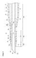
- FIG. 1is a perspective view of a catheter assembly according to an embodiment of the present invention. It is sectional drawing of the front-end
- FIG. 11is a second explanatory diagram of a procedure using the catheter assembly. It is the 3rd explanatory view of the procedure using a catheter assembly. It is the 4th explanatory view of the procedure using a catheter assembly. It is sectional drawing of the front-end
- FIG. 9Ais a first operation explanatory view of the catheter assembly shown in FIG. 8.
- FIG. 9Bis a second operation explanatory view of the catheter assembly shown in FIG. 8.
- the catheter assembly 10 shown in the initial state in FIG. 1is applied when performing infusion, blood transfusion, or the like on a patient (living body), and is punctured and detained in a patient's body to construct an introduction portion for a drug solution or the like.
- the catheter assembly 10can be configured as a catheter that is longer than a peripheral venous catheter (eg, a central venous catheter, a PICC, a midline catheter, etc.).
- the catheter assembly 10may be configured as a peripheral venous catheter.
- the catheter assembly 10is not limited to a venous catheter, and may be configured as an arterial catheter such as a peripheral arterial catheter.
- the catheter assembly 10includes a catheter 12, a catheter hub 14 for fixedly holding the catheter 12, a hollow inner needle 16 removably inserted into the catheter 12, and a fixed inner needle 16. It has a needle hub 18 for holding and a catheter operation member 20 mounted on the catheter hub 14.
- the inner needle 16may be a solid needle.
- the catheter assembly 10has a multi-tube structure (multi-tube portion) in which the catheter 12 and the inner needle 16 are sequentially stacked.
- the catheter 12has flexibility, and has a lumen 13 formed therein.
- the lumen 13is formed to have a diameter capable of accommodating the inner needle 16 and allowing a medical solution, blood, or the like to flow.
- the distal end of the catheter 12is reduced in diameter in order to reduce puncture resistance, and in the initial state of the catheter assembly 10, the inner surface of the catheter 12 and the outer surface of the inner needle 16 are in close contact with each other at the reduced diameter portion.
- the length of the catheter 12is not particularly limited and can be appropriately designed according to the application and various conditions. For example, the length is set to about 14 to 500 mm, or about 30 to 400 mm, or about 76 to 200 mm. Is set.
- a catheter member 17is constituted by the catheter 12 and the catheter hub 14.
- the catheter hub 14is exposed on the patient's skin in a state where the catheter 12 is inserted into a blood vessel, attached with a tape or the like, and is placed together with the catheter 12.
- the catheter hub 14is formed in a cylindrical shape that tapers in the distal direction.
- the constituent material of the catheter hub 14is not particularly limited.
- a thermoplastic resinsuch as polypropylene, polycarbonate, polyamide, polysulfone, polyarylate, methacrylate-butylene-styrene copolymer, or polyurethane may be used.
- a hollow portion 15is provided inside the catheter hub 14 so as to communicate with the lumen 13 of the catheter 12 and through which the infusion solution can flow.
- the hollow portion 15may house a hemostatic valve, a plug, or the like (not shown) that prevents backflow of blood when the inner needle 16 is punctured and enables infusion when the connector of the infusion tube is inserted.
- the inner needle 16is formed as a rigid hollow tube capable of piercing the skin of a living body, and is disposed so as to penetrate the lumen 13 of the catheter 12 and the hollow portion 15 of the catheter hub 14.
- the inner needle 16is formed to be longer than the catheter 12 and has a sharp needle tip 16a at its tip.
- a lumen that penetrates the inner needle 16 in the axial directionis provided inside the inner needle 16, and the lumen communicates with the distal end opening of the inner needle 16.
- a metal materialsuch as stainless steel, aluminum or an aluminum alloy, titanium or a titanium alloy, a hard resin, ceramics, and the like can be given.
- the needle hub 18has a needle holding member 22 fixed to the proximal end of the inner needle 16, and a housing 24 to which the needle holding member 22 is fixed and extends along the inner needle 16 and the catheter 12.
- the catheter assembly 10accommodates a part of the multi-tube portion, the catheter hub 14 and the catheter operation member 20 in the housing 24.
- the resin material constituting the needle holding member 22 and the housing 24is not particularly limited, for example, the materials listed for the catheter hub 14 can be appropriately selected.
- the needle holding member 22 and the housing 24may be integrally formed.
- the needle hub 18holds the inner needle 16 in the needle holding member 22, when the needle hub 18 is moved in the proximal direction with respect to the catheter 12, the inner needle 16 is also moved with the movement of the needle hub 18. 12 in the proximal direction.
- the catheter operation member 20is mounted on the catheter hub 14. For this reason, when the catheter operation member 20 is advanced relatively to the needle hub 18, the catheter member 17 advances relatively to the inner needle 16.
- the catheter operation member 20includes a hub mounting portion 20a detachably mounted on the catheter hub 14, and an operation plate portion 20b extending in a distal direction along the catheter 12 from the hub mounting portion 20a. In the catheter assembly 10, the catheter operation member 20 may not be provided.
- the catheter assembly 10has a support member 26 provided on the distal end side of the housing 24 to support the lower side of the catheter 12 held by the catheter operation member 20.
- the support member 26is rotatably attached to an arrangement recess 24 a provided at the tip of the housing 24.
- the distal end portion of the catheter operation member 20 and the support member 26constitute a deflection suppressing mechanism 27.
- the distal end of the catheter operating member 20supports the catheter 12 from above and the support member 26 supports the catheter 12 from below, so that the catheter 12 and the inner needle 16 bend. Is suppressed.
- the support member 26is rotated toward the outside of the housing 24 by being pushed by the hub mounting portion 20a, so that the catheter hub 14 is detached from the housing 24 in the distal direction. be able to. Note that the support member 26 may not be provided.
- the catheter 12has a contact portion 30 that is in close contact with the outer peripheral surface of the inner needle 16 on at least a part of the inner peripheral surface.
- the contact portion 30is provided on the inner peripheral surface of the distal end portion of the catheter 12.
- a flow path for flashback confirmation(hereinafter, referred to as “flashback flow path 32”) is formed between the catheter 12 and the inner needle 16 and closer to the base end than the close contact portion 30.
- the flashback channel 32extends to the proximal opening of the catheter 12.
- the catheter 12has a catheter body 34 that constitutes a main part of the catheter 12, and a flexible portion 38 provided at a distal end of the catheter body 34. Therefore, the distal end of the catheter 12 is more flexible toward the distal end.
- the flexible portion 38is exposed from the housing 24 (FIG. 1).
- the catheter body 34occupies most of the entire length of the catheter 12. Therefore, the distal end of the catheter body 34 is located near the distal end of the catheter 12.
- the catheter 12 and the flexible portion 38are made of a flexible resin material.
- the creep strain of the catheter body 34is larger than the creep strain of the flexible portion 38.
- the catheter body 34has a straight portion 34a having a constant outer diameter along the axial direction, a tapered portion 34b extending from the straight portion 34a in the distal direction and having an outer diameter decreasing in the distal direction, and a tapered portion 34b.
- a distal end component 34cextending in the distal direction and constituting the distal end of the catheter body 34.
- the inner peripheral surface of the distal end portion 34cis in close contact (fitting) with the outer peripheral surface of the inner needle 16 over the entire periphery in a liquid-tight manner.
- the flashback channel 32is formed between the inner peripheral surface of the catheter body 34 (specifically, the straight portion 34a and the tapered portion 34b) and the outer peripheral surface of the inner needle 16. At least the catheter body 34 of the catheter body 34 and the flexible portion 38 has transparency so that flashback can be confirmed.
- the catheter 12is supported by the support member 26 (FIG. 1) at the position of the catheter body 34 (the catheter body 34 is supported by the support member 26).
- the catheter 12can be reliably supported, and the sliding resistance when the catheter 12 is advanced can be reduced.
- the portion supported by the support member 26 (FIG. 1)is located on the base end side of the interface 42 between the catheter body 34 and the flexible portion 38, the catheter 12 slides with respect to the support member 26. Peeling of the interface 42 due to this can be prevented.
- the catheter body 34does not easily swell compared to the flexible portion 38. Accordingly, during steam sterilization (autoclave sterilization) or ethylene oxide gas sterilization in the manufacturing process of the catheter assembly 10, the axial distance between the most proximal position of the blade surface 16b of the inner needle 16 and the most distal position of the catheter 12 is desired. Can be set to the size of each product, so that variations among products can be reduced.
- the catheter body 34is made of the first material.
- the first materialinclude fluorinated resins such as polytetrafluoroethylene (PTFE), ethylene / tetrafluoroethylene copolymer (ETFE), and perfluoroalkoxy fluororesin (PFA), and olefinic resins such as polyethylene and polypropylene. Or a mixture thereof, a polyurethane, a polyester, a polyamide, a polyether nylon resin, a mixture of an olefin resin and an ethylene / vinyl acetate copolymer, and the like.
- the durometer hardness of the catheter body 34is, for example, less than D70.
- the flexible portion 38includes the distal end of the catheter 12.
- the flexible portion 38is more flexible than the catheter body 34. That is, the elastic modulus k1 of the catheter body 34 and the elastic modulus k2 of the flexible portion 38 have a relationship of k1> k2.
- the flexible portion 38has a straight portion 38a having a constant outer diameter along the axial direction, and a tapered portion 38b extending from the straight portion 38a in the distal direction and decreasing in outer diameter in the distal direction.
- the inner peripheral surface of the flexible portion 38is in liquid-tight contact (fit) with the outer peripheral surface of the inner needle 16 over the entire circumference.
- the flexible portion 38 of the catheter body 34 and the flexible portion 38has X-ray contrast.
- the contrast layer in the case where the flexible portion 38 has contrast propertiesmay be provided in any form of, for example, a stripe, an intermediate layer in a radial direction, or the whole.
- the flexible part 38is made of the second material.
- the second materialinclude various rubber materials such as natural rubber, butyl rubber, isoprene rubber, butadiene rubber, styrene-butadiene rubber, and silicone rubber; polyurethane, polyester, polyamide, olefin, and styrene. Of various thermoplastic elastomers, or mixtures thereof.
- the change in flexibility between 25 ° C. and 37 ° C. of the second material (the constituent material of the flexible portion 38)is between 25 ° C. and 37 ° C. of the first material (the constituent material of the catheter body 34). Less than a change in flexibility.
- Each change in flexibilitycan be recognized as a change in elastic modulus. For example, when the elastic moduli at 25 ° C. and 37 ° C. of the first material are H1a and H1b, respectively, the change (degree of change) of the elastic modulus between 25 ° C. and 37 ° C. of the first material is H1a. / H1b. Assuming that the elastic moduli of the second material at 25 ° C. and 37 ° C.
- H2a and H2brespectively, the change (degree of change) of the elastic modulus of the second material between 25 ° C. and 37 ° C. is H2a / H2b. It is. Therefore, H2a / H2b ⁇ H1a / H1b is satisfied.
- the first material and the second materialhas an elastic modulus at 37 ° C. lower than that at 25 ° C. That is, the catheter body 34 and the flexible portion 38 after the indwelling of the catheter 12 are warmed by the body temperature and softened, and become more flexible than when the catheter 12 is inserted into a human (and before insertion).
- the first material and the second materialmay be the same type of materials having different hardnesses. For example, even if the first material and the second material are the same type of material, the above-mentioned change in the elastic modulus due to the temperature can be varied depending on the average molecular weight, the functional group, the additive, and the like.
- the catheter body 34 and the mixed area 40C in which the flexible part 38 existsare arranged in the axial direction.
- an interface 42 between the catheter body 34 and the flexible portion 38is formed in a tapered shape inclined at a substantially constant angle with respect to the axis of the catheter 12.
- the catheter main body unit region 40Ais a portion of the catheter main body 34 that is located on the base end side of the most proximal end of the flexible portion 38.
- the ⁇ flexible portion single region 40Bis a portion of the ⁇ exible portion 38 that is located on the distal end side of the distal end portion of the catheter body 34.
- the length L1 in the axial direction of the flexible portion single region 40Bis set, for example, to 0.3 to 5.0 mm, preferably to 0.4 to 2.0 mm, and more preferably to 0.5 to 0.9 mm. Is set.
- the hardness of the flexible portion 38 (flexible portion single region 40B)is, for example, A80 to D67 at 23 ° C., and preferably D53 to D64.
- the flexible portion 38 in the illustrated exampleis joined to the catheter body 34.
- the axial length L1 and the hardness of the flexible portion single region 40Bin the above ranges, it is possible to prevent the distal end (the flexible portion 38) of the catheter 12 from being turned up at the time of puncturing. Further, it is possible to appropriately suppress the catch on the blood vessel rear wall 50a when the catheter 12 is inserted. Furthermore, the collapse of the tip of the catheter 12 during blood suction can be suppressed.
- the mixed region 40Cis a portion where the catheter body 34 and the flexible portion 38 are laminated in the radial direction.
- the axial length L2 of the mixed area 40Cis set, for example, to 1 to 5 mm, and preferably to 2 to 3 mm.
- the interface 42 between the catheter body 34 and the flexible portion 38is inclined so as to approach the axis (center) of the catheter 12 toward the distal end. Therefore, in the mixed region 40C, the flexible portion 38 exists outside the catheter body 34.
- the catheter 12may be formed so as to become softer toward the distal end by changing the amount of the material having different hardness in the axial direction.
- the extrusion moldingmay be performed while changing the extrusion speed of different materials.
- the content of the plasticizer at the distal end of the catheter 12may be increased.
- a plasticizermay be applied to the distal end of the catheter 12.
- a back cut portion 16 cwhich is continuous with the needle tip 16 a and is inclined in the direction opposite to the blade surface 16 b with respect to the axis of the inner needle 16.
- the inner needle 16is provided with an introduction path 44 that communicates with the flashback channel 32 and introduces blood into the flashback channel 32.
- the introduction path 44 shown in FIG. 2is a side hole 44A that penetrates the wall of the inner needle 16 in the radial direction.
- the introduction path 44may be a groove 44 ⁇ / b> B extending in the axial direction on the outer peripheral surface of the inner needle 16.
- the proximal end 44a of the introduction path 44is provided on the proximal side with respect to the axial center position Pc of the flexible portion unit region 40B. More specifically, at least the proximal end 44a of the introduction path 44 is provided closer to the proximal end than the most distal end of the catheter main body unit region 40A.
- the whole side hole 44A shown in FIG. 2is provided on the base end side of the distal end portion of the catheter body single body region 40A. Note that a part of the side hole 44A may be present on the distal end side of the distal end portion of the catheter main body unit region 40A.
- the entire side hole 44Ais provided on the base end side of the mixed area 40C.
- a part of the side hole 44Amay be present on the distal end side of the base end of the mixed area 40C.
- the proximal end 44a of the introduction path 44(side hole 44A, groove 44B) is in close contact with the catheter assembly 10 shown in FIGS. It is provided closer to the base end than the part 30.
- the entire side hole 44 ⁇ / b> A shown in FIG. 2is provided on the base end side of the contact portion 30.
- a puncture operation of puncturing the catheter assembly 10 into the skin of a patientis performed.
- the tourniquet 54Prior to this puncture operation, as shown in FIG.
- the tourniquet 54is wound around the center side (closer to the heart) than the planned site SP (step of attaching the tourniquet).
- the blood vessel 50(vein) is compressed, thereby narrowing or collapsing the blood vessel 50.
- a part of the human body illustrated in FIG. 4is an arm 56 (specifically, a forearm).
- the tourniquet 54may be wound around the upper arm, and the puncture site SP may be located on the upper arm distal to the tourniquet 54.
- the planned puncture site SPis in the lower limb, and the tourniquet 54 may be wound more centrally than the planned puncture site SP in the lower limb.
- a puncturing operationis performed.
- a userdoctor, nurse, etc. presses the distal end of the catheter assembly 10 against the patient while holding the housing 24 shown in FIG. Puncture the skin S. Thereby, as shown in FIG. 5, each tip of inner needle 16 and catheter 12 is punctured into skin S (puncture step).
- the useroperates the catheter operating member 20 in the distal direction to move the catheter member 17 (the catheter 12 and the catheter hub 14) to the central side.
- Catheter advance stepthe catheter 12 is inserted to a target position in the blood vessel.
- the tourniquet 54is wrapped around a part of the human body, so that the narrowed or crushed portion 50 n is smaller than when the tourniquet 54 is not wound.
- itpasses through the flexible portion 38 of the catheter 12 (passing step).
- the catheter 12is indicated by a virtual line.
- the userpulls the housing 24 in the proximal direction while holding the positions of the catheter operation member 20 and the catheter member 17 shown in FIG. As a result, the catheter member 17 and the catheter operation member 20 completely exit from the housing 24, and the inner needle 16 is withdrawn from the catheter 12 in the proximal direction.
- the catheter operation member 20is removed from the catheter hub 14. Thereby, the catheter member 17 is left in the patient.
- the catheter operation member 20may be left attached to the catheter hub 14 depending on the user's preference.
- a connector of an infusion tube(not shown) is connected to the proximal end side (the proximal end portion of the catheter hub 14) of the catheter member 17 from which the inner needle 16 has been removed, and an infusion agent (medical solution) from the infusion tube to the patient is connected. ) Is administered.
- the catheter assembly 10 according to the present embodimenthas the following effects.
- the distal end portion of the catheter body 34is provided with a flexible portion 38 that is more flexible than the catheter body 34. Therefore, as shown in FIG. 6, even when the puncture angle which is the angle between the central axis of the blood vessel 50 to be punctured and the central axis of the inner needle 16 to be punctured is large, the distal end of the catheter assembly 10 is punctured into the skin S.
- the catheter 12is advanced to insert the catheter 12 into the blood vessel 50 later, the distal end of the catheter 12 is prevented from being caught on the blood vessel posterior wall 50a, which is the blood vessel wall opposite to the puncture site in the blood vessel 50. It is possible to do.
- the flexible portion 38comes into contact with the blood vessel posterior wall 50a and is easily deformed by being pushed by the blood vessel posterior wall 50a. It is possible to prevent the hook 50a from being caught. Accordingly, it is possible to prevent the catheter 12 from being unable to be inserted into the blood vessel 50, and prevent the distal end of the catheter 12 from damaging the blood vessel rear wall 50a.
- the change in the flexibility of the second material forming the flexible portion 38 between 25 ° C. and 37 ° C.is caused by the change in the flexibility of the first material forming the catheter body 34 between 25 ° C. and 37 ° C. Therefore, when the catheter 12 is inserted into the living body, the distal end of the catheter 12 is relatively soft, so that the blood vessel 50 is not easily damaged, and the catheter body 34 is relatively hard, so that it is easy to insert. After the catheter 12 is placed, the flexible portion 38 constituting the distal end of the catheter 12 is not so soft as compared with the insertion, so that the flexible portion 38 is not easily crushed during blood suction.
- the catheter body 34becomes softer than at the time of insertion and adapts to the shape of the blood vessel 50 (usually, it is not straight but slightly curved) due to human body temperature. Is reduced. For this reason, it is possible to reduce discomfort, occurrence of phlebitis, and occurrence of extravasation given to the patient during placement of the catheter 12.
- a flashback channel 32is formed between the catheter 12 and the inner needle 16.
- the inner needle 16communicates with the flashback channel 32, and An introduction path 44 for introducing blood is provided.
- the proximal end 44a of the introduction path 44is provided on the proximal end side with respect to the axial center position Pc of a portion of the flexible portion 38 located on the distal end side of the distal end portion of the catheter body 34.
- the catheter 12has the contact portion 30 in which at least a part of the inner peripheral surface is in close contact with the outer peripheral surface of the inner needle 16, and at least the proximal end 44 a of the introduction path 44 is provided on the proximal end side with respect to the contact portion 30. Have been.
- both the flexible portion 38 and the catheter body 34are in close contact with the inner needle 16. With this configuration, an appropriate fitting force between the inner needle 16 and the catheter 12 can be obtained. With an appropriate fitting force, turning of the flexible portion 38 when puncturing the skin is suppressed, and the inner needle 16 can be easily removed from the catheter 12.
- the catheter 12is advanced while the tourniquet 54 is wound, and thus the catheter is caused by vasoconstriction that occurs when the tourniquet 54 is removed. 12 can be prevented from falling off.
- the flexible portion 38is provided at the distal end of the catheter 12, the catheter 12 passes from the peripheral side A to the central side B through the blood vessel 50 (part 50n) narrowed by the tourniquet 54, as shown in FIG. In doing so, the flexible portion 38 is easily deformed, and easily enters the narrowed portion 50n of the blood vessel 50. This allows the catheter 12 to easily pass through the portion 50n of the blood vessel 50 narrowed by the tourniquet 54, and suppresses damage to the blood vessel 50 due to the passage of the catheter 12.
- a catheter and an inner needle inserted through the catheterwherein the catheter is provided at a distal end of the catheter main body and the catheter main body, includes a distal end of the catheter, and is more flexible than the catheter main body.
- Preparing a catheter assembly having a flexible portionWrap the tourniquet around a central part of the part of the human body that is to be punctured, Piercing the inner needle of the catheter assembly into a blood vessel at the site to be punctured in a part of the human body, Advancing the catheter within the vessel; A catheter assembly that passes the flexible portion to a portion of the blood vessel that is narrower than when the tourniquet is not wound by being wound around a part of the human body; Insertion method.
- the catheter 12ahas a side hole 60 opened to the close contact portion 30.
- the catheter 12ais configured similarly to the catheter 12 (FIG. 1 and the like) except that the side hole 60 is provided.
- a plurality of side holes 60are provided at intervals in the circumferential direction.
- the side hole 60is provided on the distal end side of the most proximal position of the contact portion 30.
- the side hole 60penetrates from the inner peripheral surface to the outer peripheral surface of the catheter 12a.
- the side hole 60penetrates both the catheter body 34 and the flexible portion 38.
- only one side hole 60may be provided in the circumferential direction.
- a plurality of side holes 60may be provided at intervals in the axial direction of the catheter 12a.
- the side hole 60may penetrate only one of the catheter body 34 and the flexible portion 38.
- the side hole 60may be provided to extend over both the catheter body 34 and the flexible portion 38.
- the side hole 60may be inclined with respect to the radial direction of the catheter 12a.
- the puncture of the catheter assembly 10a into the blood vessel 50causes the flushing of the inner needle 16 through the lumen and the introduction path 44. Blood flows into the back channel 32.
- the catheter 12ais provided with a side hole 60, the side hole 60 is opened at the close contact portion 30 and is not opened at the flashback channel 32, so that blood flows from the flashback channel 32 to the side hole. It does not leak out of the catheter 12a via 60.
- the catheter 12ais provided with a side hole 60 opening to the mixed area 40C. Since the mixed region 40C includes the catheter body 34, it is relatively harder than the flexible portion single region 40B.
- the catheterAn inner needle inserted through the catheter,
- the catheteris A catheter body, provided at the distal end of the catheter body, including the distal end of the catheter, having a flexible portion that is more flexible than the catheter body,
- the catheterhas a contact portion in which at least a part of the inner peripheral surface is in close contact with the outer peripheral surface of the inner needle, and in the contact portion, both the flexible portion and the catheter body are in close contact with the inner needle.
- the catheteris provided with a side hole that opens to the close contact portion, A flow path for flashback confirmation is formed between the catheter and the inner needle,
- the catheter assemblywherein the inner needle is provided with an introduction passage communicating with the flow passage and introducing blood into the flow passage.
- the physical properties of the first material forming the catheter body 34 and the second material forming the flexible portion 38 in the catheter assembly 10a shown in FIG. 8are not limited to the above-described combinations.
- the change in flexibility at 25 ° C. and 37 ° C. in the second materialmay be the same or greater than the change in flexibility at 25 ° C. and 37 ° C. in the first material.
Landscapes
- Health & Medical Sciences (AREA)
- Life Sciences & Earth Sciences (AREA)
- Animal Behavior & Ethology (AREA)
- Veterinary Medicine (AREA)
- Public Health (AREA)
- General Health & Medical Sciences (AREA)
- Engineering & Computer Science (AREA)
- Heart & Thoracic Surgery (AREA)
- Hematology (AREA)
- Biomedical Technology (AREA)
- Anesthesiology (AREA)
- Pulmonology (AREA)
- Biophysics (AREA)
- Epidemiology (AREA)
- Chemical & Material Sciences (AREA)
- Chemical Kinetics & Catalysis (AREA)
- Media Introduction/Drainage Providing Device (AREA)
Abstract
Description
Translated fromJapanese本発明は、例えば患者に対して輸液等を行うに際して血管に穿刺し、留置するカテーテル組立体に関する。The present invention relates to a catheter assembly that punctures a blood vessel and indwells it, for example, when performing infusion or the like on a patient.
従来、患者に対し輸液等を行う際に使用されるカテーテル組立体は公知である。この種のカテーテル組立体は、中空のカテーテルと、カテーテルの基端に固着されたカテーテルハブと、カテーテル内に挿入され先端に鋭利な針先を有する中空の内針と、この内針の基端に固着された針ハブとを備える(例えば、特開2008-43445号公報を参照)。カテーテル組立体を使用する場合、内針及びカテーテルの各先端が生体の皮膚及び血管に穿刺された後、カテーテルが内針に対して進められることで、カテーテルが血管内に所定長さ挿入される。カ テ ー テ ル Conventionally, a catheter assembly used for performing infusion or the like on a patient is known. This type of catheter assembly includes a hollow catheter, a catheter hub fixed to the proximal end of the catheter, a hollow inner needle inserted into the catheter and having a sharp tip at the distal end, and a proximal end of the inner needle. (See, for example, JP-A-2008-43445). When using the catheter assembly, after the inner needle and each tip of the catheter are pierced into the skin and blood vessel of the living body, the catheter is advanced to the inner needle, so that the catheter is inserted into the blood vessel for a predetermined length. .
従来の内針及びカテーテルを備えたカテーテル組立体では、穿刺角度が大きい場合、カテーテル先端が血管後壁(穿刺箇所に対向する血管壁)に引っ掛かることがある。その結果、カテーテルが血管に挿入できなくなったり、カテーテル先端で血管壁を傷つけたりする。カ テ ー テ ル In a conventional catheter assembly including an inner needle and a catheter, when the puncture angle is large, the tip of the catheter may be caught on the back wall of the blood vessel (the blood vessel wall facing the puncture site). As a result, the catheter cannot be inserted into the blood vessel, or the blood vessel wall may be damaged at the tip of the catheter.
本発明はこのような課題を考慮してなされたものであり、穿刺される血管の中心軸と穿刺する内針の中心軸の角度である穿刺角度が大きい場合でも血管へのカテーテル前進時にカテーテル先端が血管後壁に引っ掛かることを抑制することが可能なカテーテル組立体を提供することを目的とする。The present invention has been made in view of such problems, and even when the puncture angle, which is the angle between the central axis of the punctured blood vessel and the central axis of the inner needle to be punctured, is large, the catheter tip can be moved forward to the blood vessel. It is an object of the present invention to provide a catheter assembly capable of suppressing the blood vessel from being caught on the back wall of a blood vessel.
本発明の一態様は、カテーテルと、前記カテーテルに挿通された内針と、を備え、前記カテーテルは、カテーテル本体と、前記カテーテル本体の先端部に設けられ、前記カテーテルの最先端部を含み、前記カテーテル本体よりも柔軟な柔軟部と、を有し、前記カテーテル本体は、第1の材料から構成され、前記柔軟部は、第2の材料から構成され、前記第2の材料の25℃と37℃との間の柔軟性の変化は、前記第1の材料の25℃と37℃との間の柔軟性の変化よりも小さい、カテーテル組立体である。One embodiment of the present invention includes a catheter and an inner needle inserted through the catheter, wherein the catheter is provided at a distal end portion of the catheter body and the catheter body, and includes a distal end portion of the catheter, A flexible portion that is more flexible than the catheter body, wherein the catheter body is made of a first material, and the flexible portion is made of a second material, and has a temperature of 25 ° C. of the second material. A catheter assembly wherein the change in flexibility between 37 ° C is less than the change in flexibility between 25 ° C and 37 ° C of the first material.
本発明のカテーテル組立体によれば、カテーテル本体の先端部にはカテーテル本体よりも柔軟な柔軟部が設けられているため、穿刺角度が大きい場合でも、カテーテル先端が血管後壁に引っ掛かることを抑制することが可能となる。これにより、カテーテルが血管に挿入できなくなったり、カテーテル先端で血管壁を傷つけたりすることを防止することができる。また、柔軟部を構成する第2の材料の25℃と37℃との間の柔軟性の変化は、カテーテル本体を構成する第1の材料の25℃と37℃との間の柔軟性の変化よりも小さいため、生体へのカテーテルの挿入時には、カテーテルの先端が柔らかいので血管を傷めにくく、カテーテル本体が硬いので挿入しやすい。カテーテルの留置後は、カテーテルの先端を構成する柔軟部が挿入時と比べてあまり柔らかくならないため、血液吸引時に柔軟部がつぶれにくい。一方、カテーテル本体は、カテーテルの留置後、体温によって挿入時よりも軟化して血管の形状になじむため、血管への刺激が低減される。According to the catheter assembly of the present invention, since the distal end portion of the catheter body is provided with a flexible portion that is more flexible than the catheter body, even when the puncture angle is large, the catheter distal end is prevented from being caught on the back wall of the blood vessel. It is possible to do. Thereby, it is possible to prevent the catheter from being inserted into the blood vessel and the blood vessel wall from being damaged by the tip of the catheter. Further, the change in the flexibility between 25 ° C. and 37 ° C. of the second material forming the flexible portion is caused by the change in the flexibility between 25 ° C. and 37 ° C. of the first material forming the catheter body. When the catheter is inserted into a living body, the tip of the catheter is soft, so that the blood vessel is not easily damaged, and the catheter body is hard, so that the catheter can be easily inserted. After indwelling the catheter, the flexible portion constituting the distal end of the catheter does not become much softer than at the time of insertion, so the flexible portion is less likely to collapse during blood suction. On the other hand, after the catheter is indwelled, the catheter body becomes softer than at the time of insertion due to body temperature and conforms to the shape of the blood vessel, so that stimulation to the blood vessel is reduced.
以下、本発明に係るカテーテル組立体について好適な実施形態を挙げ、添付の図面を参照しながら説明する。Hereinafter, preferred embodiments of the catheter assembly according to the present invention will be described with reference to the accompanying drawings.
図1に初期状態を示すカテーテル組立体10は、患者(生体)に輸液や輸血等を行う場合に適用され、患者の体内に穿刺及び留置されて薬液等の導入部を構築する。カテーテル組立体10は、末梢静脈カテーテルよりも長さが長いカテーテル(例えば、中心静脈カテーテル、PICC、ミッドラインカテーテル等)として構成され得る。なお、カテーテル組立体10は、末梢静脈カテーテルとして構成されてもよい。また、カテーテル組立体10は、静脈用カテーテルに限らず、末梢動脈カテーテル等の動脈用カテーテルとして構成されてもよい。カ テ ー テ ル The
カテーテル組立体10は、図1に示すように、カテーテル12と、カテーテル12を固定保持するカテーテルハブ14と、カテーテル12内に抜去可能に挿入される中空の内針16と、内針16を固定保持する針ハブ18と、カテーテルハブ14に装着されるカテーテル操作部材20とを備える。内針16は、中実針であってもよい。As shown in FIG. 1, the
カテーテル組立体10は、使用前の初期状態で、カテーテル12及び内針16を順に重ねた多重管構造(多重管部)を形成している。In the initial state before use, the
カテーテル12は、可撓性を有し、内部に内腔13が貫通形成されている。内腔13は、内針16を収容可能且つ薬液や血液等を流動可能な直径に形成される。穿刺抵抗を減らすためにカテーテル12の先端は縮径しており、カテーテル組立体10の初期状態では、当該縮径部分でカテーテル12の内面と内針16の外面とが密着している。カテーテル12の長さは、特に限定されず用途や諸条件等に応じて適宜設計可能であり、例えば、14~500mm程度に設定され、あるいは30~400mm程度に設定され、あるいは76~200mm程度に設定される。The
カテーテル12の基端部は、カテーテルハブ14内の先端部に固定されている。カテーテル12とカテーテルハブ14により、カテーテル部材17が構成されている。基 The proximal end of the
カテーテルハブ14は、カテーテル12が血管内に挿入された状態で患者の皮膚上に露出され、テープ等により貼り付けられてカテーテル12とともに留置される。カテーテルハブ14は、先端方向に先細りの筒状に形成される。The
カテーテルハブ14の構成材料は、特に限定されるものではないが、例えば、ポリプロピレン、ポリカーボネート、ポリアミド、ポリスルホン、ポリアリレート、メタクリレート-ブチレン-スチレン共重合体、ポリウレタン等の熱可塑性樹脂を適用するとよい。The constituent material of the
カテーテルハブ14の内部には、カテーテル12の内腔13に連通して輸液剤を流通可能な中空部15が設けられている。この中空部15には、内針16の穿刺時に血液の逆流を防ぐとともに、輸液チューブのコネクタの挿入に伴い輸液を可能とする、図示しない止血弁やプラグ等が収容されてもよい。中空 A
内針16は、生体の皮膚を穿刺可能な剛性を有する中空管に構成され、カテーテル12の内腔13及びカテーテルハブ14の中空部15に貫通配置される。内針16は、カテーテル12よりも長い全長に形成され、その先端には鋭利な針先16aが設けられる。内針16の内部には、内針16の軸方向に貫通するルーメンが設けられ、このルーメンは、内針16の先端開口に連通する。The
内針16の構成材料としては、例えば、ステンレス鋼、アルミニウム又はアルミニウム合金、チタン又はチタン合金のような金属材料、硬質樹脂、セラミックス等が挙げられる。構成 As a constituent material of the
針ハブ18は、内針16の基端部に固定された針保持部材22と、針保持部材22が固定されるとともに内針16及びカテーテル12に沿って延在するハウジング24とを有する。カテーテル組立体10は、初期状態で、多重管部の一部、カテーテルハブ14及びカテーテル操作部材20をハウジング24内に収容している。針保持部材22及びハウジング24を構成する樹脂材料は、特に限定されるものではないが、例えば、カテーテルハブ14で挙げた材料を適宜選択し得る。なお、針保持部材22及びハウジング24は一体成形されていてもよい。The
針ハブ18は、針保持部材22において内針16を保持しているため、カテーテル12に対して針ハブ18を基端方向に移動させると、針ハブ18の移動に伴って内針16もカテーテル12に対して基端方向に移動させられる。Since the
カテーテル操作部材20は、カテーテルハブ14に装着されている。このため、カテーテル操作部材20を針ハブ18に対して相対的に前進させると、カテーテル部材17が内針16に対して相対的に前進する。カテーテル操作部材20は、カテーテルハブ14に着脱自在に装着されるハブ装着部20aと、ハブ装着部20aからカテーテル12に沿って先端方向に延在する操作板部20bとを有する。なお、カテーテル組立体10において、カテーテル操作部材20は設けられていなくてもよい。The
カテーテル組立体10は、カテーテル操作部材20に保持されたカテーテル12の下側を支えるため、ハウジング24の先端側に支持部材26を設けている。支持部材26は、ハウジング24の先端部に設けられた配置用凹部24aに回転自在に取り付けられている。カテーテル操作部材20の先端部と支持部材26とにより、撓み抑制機構27が構成されている。The
内針16及びカテーテル12の皮膚への穿刺時、カテーテル操作部材20の先端部がカテーテル12を上方から支持するとともに支持部材26がカテーテル12を下方から支持するため、カテーテル12及び内針16の撓みが抑制される。カテーテル操作部材20がハウジング24から抜け出す際には、ハブ装着部20aに押されることで支持部材26はハウジング24の外側に向かって回転させられるため、カテーテルハブ14はハウジング24から先端方向に離脱することができる。なお、支持部材26は設けられていなくてもよい。When the
図2に示すように、カテーテル12は、内周面の少なくとも一部に、内針16の外周面と密着した密着部30を有する。密着部30は、カテーテル12の先端部の内周面に設けられている。カテーテル12と内針16との間であって、密着部30よりも基端側には、フラッシュバック確認用の流路(以下、「フラッシュバック流路32」という)が形成されている。フラッシュバック流路32は、カテーテル12の基端開口まで延在している。カ テ ー テ ル As shown in FIG. 2, the
カテーテル12は、当該カテーテル12の主要部を構成するカテーテル本体34と、カテーテル本体34の先端部に設けられた柔軟部38とを有する。このため、カテーテル12の先端側では、最先端部に向かってより柔軟になっている。柔軟部38は、ハウジング24(図1)から露出している。The
カテーテル本体34は、カテーテル12の全長の大部分を占めている。このため、カテーテル本体34の最先端部は、カテーテル12の最先端近傍に位置する。カテーテル12及び柔軟部38は、可撓性を有する樹脂材料により構成されている。カテーテル本体34のクリープひずみは、柔軟部38のクリープひずみよりも大きい。The
カテーテル本体34は、軸方向に沿って外径が一定のストレート部34aと、ストレート部34aから先端方向に延出するとともに先端方向に向かって外径が減少するテーパ部34bと、テーパ部34bから先端方向に延出するとともにカテーテル本体34の最先端部までを構成する先端構成部34cとを有する。先端構成部34cの内周面は、内針16の外周面と全周に亘って液密に密着(嵌合)している。The
フラッシュバック流路32は、カテーテル本体34(具体的には、ストレート部34a及びテーパ部34b)の内周面と、内針16の外周面との間に形成されている。フラッシュバックを確認できるように、カテーテル本体34及び柔軟部38のうち少なくともカテーテル本体34は透明性を有する。The
カテーテル12は、カテーテル本体34の箇所で、支持部材26(図1)によって支持されている(カテーテル本体34が支持部材26によって支持されている)。これにより、確実にカテーテル12を支持することができるとともに、カテーテル12を前進させる際の摺動抵抗を低くすることができる。しかも、支持部材26(図1)によって支持される部分が、カテーテル本体34と柔軟部38との界面42よりも基端側に位置するため、支持部材26に対してカテーテル12が摺動することによる界面42の剥がれを防止することができる。The
カテーテル本体34は、柔軟部38と比較して膨潤しにくいことが好ましい。これにより、カテーテル組立体10の製造工程における水蒸気滅菌(オートクレーブ滅菌)やエチレンオキサイドガス滅菌時に、内針16の刃面16bの最基端位置とカテーテル12の最先端位置との軸方向距離を所望の大きさに設定することができ、製品毎のバラツキを少なくすることができる。It is preferable that the
カテーテル本体34は、第1の材料から構成されている。第1の材料としては、例えば、ポリテトラフルオロエチレン(PTFE)、エチレン・テトラフルオロエチレン共重合体(ETFE)、ペルフルオロアルコキシフッ素樹脂(PFA)等のフッ素系樹脂、ポリエチレン、ポリプロピレン等のオレフィン系樹脂又はこれらの混合物、ポリウレタン、ポリエステル、ポリアミド、ポリエーテルナイロン樹脂、オレフィン系樹脂とエチレン・酢酸ビニル共重合体との混合物等が挙げられる。カテーテル本体34のデュロメータ硬さは、例えば、D70未満である。The
柔軟部38は、カテーテル12の最先端部を含む。柔軟部38は、カテーテル本体34よりも柔軟である。すなわち、カテーテル本体34の弾性率k1と、柔軟部38の弾性率k2とは、k1>k2の関係を有する。The
柔軟部38は、軸方向に沿って外径が一定のストレート部38aと、ストレート部38aから先端方向に延出するとともに先端方向に向かって外径が減少するテーパ部38bとを有する。柔軟部38の内周面は、内針16の外周面と全周に亘って液密に密着(嵌合)している。The
カテーテル本体34及び柔軟部38のうち少なくとも柔軟部38はX線造影性を有していることが好ましい。これにより、例えば、血管内でカテーテル12が離断した際に、離断して血管内に残されたカテーテル12の場所をX線により容易に確認することができる。柔軟部38が造影性を有する場合の造影層は、例えば、ストライプ状、径方向の中間層、全体のいずれかの形態で設けられるとよい。It is preferable that at least the
柔軟部38は、第2の材料から構成されている。第2の材料としては、例えば、天然ゴム、ブチルゴム、イソプレンゴム、ブタジエンゴム、スチレン-ブタジエンゴム、シリコーンゴムのような各種ゴム材料や、ポリウレタン系、ポリエステル系、ポリアミド系、オレフィン系、スチレン系等の各種熱可塑性エラストマー、あるいはそれらの混合物等が挙げられる。The
第2の材料(柔軟部38の構成材料)の25℃と37℃との間の柔軟性の変化は、第1の材料(カテーテル本体34の構成材料)の25℃と37℃との間の柔軟性の変化よりも小さい。それぞれの柔軟性の変化は弾性率の変化として認識できる。例えば、第1の材料の25℃、37℃での弾性率をそれぞれH1a、H1bとした場合、第1の材料の25℃と37℃との間の弾性率の変化(変化度)は、H1a/H1bである。第2の材料の25℃、37℃での弾性率をそれぞれH2a、H2bとした場合、第2の材料の25℃と37℃との間の弾性率の変化(変化度)は、H2a/H2bである。従って、H2a/H2b<H1a/H1bが成立する。The change in flexibility between 25 ° C. and 37 ° C. of the second material (the constituent material of the flexible portion 38) is between 25 ° C. and 37 ° C. of the first material (the constituent material of the catheter body 34). Less than a change in flexibility. Each change in flexibility can be recognized as a change in elastic modulus. For example, when the elastic moduli at 25 ° C. and 37 ° C. of the first material are H1a and H1b, respectively, the change (degree of change) of the elastic modulus between 25 ° C. and 37 ° C. of the first material is H1a. / H1b. Assuming that the elastic moduli of the second material at 25 ° C. and 37 ° C. are H2a and H2b, respectively, the change (degree of change) of the elastic modulus of the second material between 25 ° C. and 37 ° C. is H2a / H2b. It is. Therefore, H2a / H2b <H1a / H1b is satisfied.
25℃は室温の代表的な温度である。37℃はヒトの体温の代表的な温度である。第1の材料と第2の材料は、いずれも、37℃における弾性率が、25℃における弾性率よりも低い。すなわち、カテーテル12の留置後におけるカテーテル本体34及び柔軟部38は、体温によって温められて軟化し、カテーテル12のヒトへの挿入時(及び挿入前)よりも柔軟になる。第1の材料と第2の材料は、互いに硬度が異なる同種の材料であってもよい。例えば、第1の材料と第2の材料とが同種の材料であっても、平均分子量、官能基、添加剤等によって、上記の温度による弾性率の変化を異ならせることができる。25 ° C. is a typical temperature of room temperature. 37 ° C. is a typical temperature of human body temperature. Each of the first material and the second material has an elastic modulus at 37 ° C. lower than that at 25 ° C. That is, the
カテーテル12では、カテーテル本体34及び柔軟部38のうちカテーテル本体34のみが存在するカテーテル本体単体領域40Aと、カテーテル本体34及び柔軟部38のうち柔軟部38のみが存在する柔軟部単体領域40Bと、カテーテル本体34及び柔軟部38が存在する混在領域40Cとが、軸方向に配置されている。図2に示すカテーテル12では、カテーテル本体34と柔軟部38との界面42は、カテーテル12の軸に対して略一定角度で傾斜するテーパ状に形成されている。In the
カテーテル本体単体領域40Aは、カテーテル本体34のうち柔軟部38の最基端部よりも基端側に存在する部分である。The catheter main
柔軟部単体領域40Bは、柔軟部38のうちカテーテル本体34の最先端部よりも先端側に存在する部分である。柔軟部単体領域40Bの軸方向長さL1は、例えば、0.3~5.0mmに設定され、好ましくは0.4~2.0mmに設定され、より好ましくは0.5~0.9mmに設定される。柔軟部38(柔軟部単体領域40B)の硬さは、23℃で、例えば、A80~D67で、好ましくはD53~D64である。図示例の柔軟部38は、カテーテル本体34に接合されている。柔軟部単体領域40Bの軸方向長さL1及び硬度が上記の範囲に設定されることにより、穿刺時のカテーテル12の先端(柔軟部38)のめくれを抑制することができる。また、カテーテル12の挿入時の血管後壁50aでの引っ掛かりを好適に抑制できる。さらに、血液吸引時のカテーテル12の先端のつぶれを抑制することができる。The 部 flexible portion
混在領域40Cは、カテーテル本体34及び柔軟部38が径方向に積層されている部分である。混在領域40Cの軸方向長さL2は、例えば、1~5mmに設定され、好ましくは2~3mmに設定される。The
図2に示すカテーテル12では、カテーテル本体34と柔軟部38との界面42は、先端方向に向かってカテーテル12の軸(中心)に近づくように傾斜している。このため、混在領域40Cでは、カテーテル本体34の外側に柔軟部38が存在している。で は In the
界面42を有する上記構成に代えて、カテーテル12は、異なる硬度の材料の配合量を軸方向に変化させることで、先端方向に向かって軟らかくなるように形成されてもよい。この場合、異なる材料の押し出し速度を変化させながら押出成形してもよい。あるいは、カテーテル12の先端部の可塑剤の含有量を増やしてもよい。この場合、カテーテル12の先端部に可塑剤を塗布してもよい。カ テ ー テ ル Instead of the above-described configuration having the
内針16において、刃面16bとは反対側には、針先16aに連なるとともに内針16の軸に対して刃面16bとは逆方向に傾斜するバックカット部16cが設けられている。On the
内針16には、フラッシュバック流路32と連通するとともに当該フラッシュバック流路32に血液を導入するための導入路44が設けられている。図2に示す導入路44は、内針16の壁部を径方向に貫通する側孔44Aである。図3のように、導入路44は、内針16の外周面において軸方向に延在した溝部44Bであってもよい。The
図2及び図3に示すカテーテル組立体10の初期状態で、導入路44の基端44aは、柔軟部単体領域40Bの軸方向中央位置Pcよりも基端側に設けられている。より具体的には、導入路44の少なくとも基端44aは、カテーテル本体単体領域40Aの最先端部よりも基端側に設けられている。図2に示す側孔44Aは、その全体が、カテーテル本体単体領域40Aの最先端部よりも基端側に設けられている。なお、側孔44Aの一部は、カテーテル本体単体領域40Aの最先端部よりも先端側に存在していてもよい。及 び In the initial state of the
図2では、側孔44Aは、その全体が、混在領域40Cよりも基端側に設けられている。側孔44Aの一部は、混在領域40Cの基端よりも先端側に存在していてもよい。で は In FIG. 2, the
密着部30との関係における導入路44の位置については、図2及び図3に示すカテーテル組立体10の初期状態で、導入路44(側孔44A、溝部44B)の少なくとも基端44aは、密着部30よりも基端側に設けられている。図2に示す側孔44Aは、その全体が、密着部30よりも基端側に設けられている。Regarding the position of the
次に、上記のように構成されたカテーテル組立体10を用いた手技(カテーテル組立体10の挿入方法)について説明する。Next, a procedure (a method of inserting the catheter assembly 10) using the
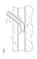
図1に示すカテーテル組立体10の使用においては、カテーテル組立体10を患者の皮膚に穿刺する穿刺操作が行われるが、この穿刺操作に先立ち、図4に示すように、人体の一部における穿刺予定部位SPよりも中枢側(心臓に近い側)に駆血帯54を巻く(駆血帯装着ステップ)。駆血帯54が巻かれた箇所では、血管50(静脈)が圧迫されることで血管50が狭くなる又はつぶれる。図4に例示した人体の一部は、腕56(具体的には前腕)である。他の態様において、駆血帯54は上腕に巻かれ、穿刺予定部位SPは駆血帯54よりも末梢側の上腕にあってもよい。他の態様において、穿刺予定部位SPは下肢にあり、駆血帯54は下肢における穿刺予定部位SPよりも中枢側に巻かれてもよい。In the use of the
このように駆血帯54を巻いた後、穿刺操作を行う。穿刺操作において、ユーザ(医師、看護師等)は、図1に示したハウジング24を把持しつつ、カテーテル組立体10の先端部を患者に押し当てるようにして、穿刺目標の血管50に向かって皮膚Sに穿刺する。これにより、図5に示すように、内針16及びカテーテル12の各先端部が皮膚Sに穿刺される(穿刺ステップ)。後 After the
次に、ユーザは、図1に示した針ハブ18(ハウジング24)の位置を固定しつつ、カテーテル操作部材20を先端方向に操作してカテーテル部材17(カテーテル12及びカテーテルハブ14)を中枢側に前進させる(カテーテル前進ステップ)。そして、カテーテル12を血管内の目標位置まで挿入する。その際、図4に示すように、血管50のうち、駆血帯54が人体の一部に巻かれることによって駆血帯54が巻かれていないときよりも狭くなった又はつぶれた部分50nに対し、カテーテル12の柔軟部38を通過させる(通過ステップ)。なお、図4においてカテーテル12は仮想線で示されている。Next, while fixing the position of the needle hub 18 (housing 24) shown in FIG. 1, the user operates the
次に、ユーザは、図1に示したカテーテル操作部材20及びカテーテル部材17の位置を保持しつつ、ハウジング24を基端方向に引っ張る。これにより、カテーテル部材17及びカテーテル操作部材20がハウジング24から完全に出るとともに、内針16がカテーテル12から基端方向に抜去される。Next, the user pulls the
次に、カテーテル操作部材20は、カテーテルハブ14から取り外される。これにより、カテーテル部材17は患者に留置される。なお、ユーザの好みによっては、カテーテル操作部材20をカテーテルハブ14に取り付けたままにしてもよい。Next, the
次に、内針16が抜き取られた状態のカテーテル部材17の基端側(カテーテルハブ14の基端部)に、図示しない輸液チューブのコネクタを接続し、輸液チューブから患者への輸液剤(薬液)の投与を実施する。Next, a connector of an infusion tube (not shown) is connected to the proximal end side (the proximal end portion of the catheter hub 14) of the
この場合、本実施形態に係るカテーテル組立体10は、以下の効果を奏する。In this case, the
カテーテル組立体10によれば、図2に示したように、カテーテル本体34の先端部にはカテーテル本体34よりも柔軟な柔軟部38が設けられている。このため、図6のように、穿刺される血管50の中心軸と穿刺する内針16の中心軸の角度である穿刺角度が大きい場合でも、カテーテル組立体10の先端部を皮膚Sに穿刺した後にカテーテル12を血管50内に挿入するためにカテーテル12を前進させる際に、カテーテル12の先端が、血管50のうち穿刺箇所とは反対側の血管壁である血管後壁50aに引っ掛かることを抑制することが可能となる。According to the
すなわち、図6のようにカテーテル12を前進させる際、柔軟部38は、血管後壁50aに接触するとともに、血管後壁50aに押されて容易に変形するため、カテーテル12の先端が血管後壁50aに引っ掛かることを抑制することができる。これにより、カテーテル12が血管50に挿入できなくなったり、カテーテル12の先端で血管後壁50aを傷つけたりすることを防止することができる。That is, when the
また、柔軟部38を構成する第2の材料の25℃と37℃との間の柔軟性の変化は、カテーテル本体34を構成する第1の材料の25℃と37℃との間の柔軟性の変化よりも小さいため、生体へのカテーテル12の挿入時には、カテーテル12の先端が比較的柔らかいので血管50を傷めにくく、カテーテル本体34が比較的硬いので挿入しやすい。カテーテル12の留置後は、カテーテル12の先端を構成する柔軟部38が挿入時と比べてあまり柔らかくならないため、血液吸引時に柔軟部38がつぶれにくい。一方、カテーテル本体34は、カテーテル12の留置後、ヒトの体温によって挿入時よりも軟化して血管50の形状(通常、直線状ではなく多少の湾曲がある)になじむため、血管50への刺激が低減される。このため、カテーテル12の留置中に患者に与える違和感、静脈炎の発生、血管外漏出の発生を低減することができる。The change in the flexibility of the second material forming the
図2に示したように、カテーテル12と内針16との間には、フラッシュバック流路32が形成され、内針16には、フラッシュバック流路32と連通し、フラッシュバック流路32に血液を導入するための導入路44が設けられている。導入路44の基端44aは、柔軟部38のうちカテーテル本体34の最先端部よりも先端側に存在する部分の軸方向中央位置Pcよりも基端側に設けられている。また、カテーテル12は、内周面の少なくとも一部が内針16の外周面と密着した密着部30を有し、導入路44の少なくとも基端44aは、密着部30よりも基端側に設けられている。As shown in FIG. 2, a
上記構成により、穿刺時に、柔軟部38が変形して導入路44が塞がれることが抑制されるため、血液のフラッシュバックを容易に確認することが可能となる。(4) According to the above configuration, since the
密着部30では、柔軟部38とカテーテル本体34の両方が内針16と密着している。この構成により、内針16とカテーテル12との適切な嵌合力が得られる。適切な嵌合力により、皮膚に穿刺する際に柔軟部38のめくれが抑制されるとともにカテーテル12より内針16が容易に抜去できる。In the
上述したカテーテル組立体10の挿入方法では、図4において仮想線で示したように、駆血帯54を巻いたままカテーテル12を進めるため、駆血帯54を外したときに起きる血管収縮によるカテーテル12の脱落を防止することができる。また、柔軟部38がカテーテル12の先端に設けられることで、図7に示すように、駆血帯54によって狭くなった血管50(部分50n)を末梢側Aから中枢側Bへカテーテル12が通過する際に、柔軟部38が容易に変形し、血管50の狭くなった部分50nに進入しやすい。これにより、駆血帯54によって狭くなった血管50の部分50nをカテーテル12が通過しやすいとともに、カテーテル12の通過に伴う血管50の損傷を抑制することができる。In the insertion method of the
上記の説明から、以下の発明(カテーテル組立体の挿入方法)が把握できる。か ら From the above description, the following invention (method of inserting a catheter assembly) can be understood.
カテーテルと、前記カテーテルに挿通された内針と、を備え、前記カテーテルは、カテーテル本体と、前記カテーテル本体の先端部に設けられ、前記カテーテルの最先端部を含み、前記カテーテル本体よりも柔軟な柔軟部と、を有するカテーテル組立体を準備し、
人体の一部における穿刺予定部位よりも中枢側に駆血帯を巻き、
前記カテーテル組立体の前記内針を、前記人体の一部における前記穿刺予定部位の血管に穿刺し、
前記カテーテルを前記血管内で前進させ、
前記血管のうち、前記駆血帯が前記人体の一部に巻かれることによって前記駆血帯が巻かれていないときよりも狭くなった部分に対し、前記柔軟部を通過させる、カテーテル組立体の挿入方法。A catheter and an inner needle inserted through the catheter, wherein the catheter is provided at a distal end of the catheter main body and the catheter main body, includes a distal end of the catheter, and is more flexible than the catheter main body. Preparing a catheter assembly having a flexible portion;
Wrap the tourniquet around a central part of the part of the human body that is to be punctured,
Piercing the inner needle of the catheter assembly into a blood vessel at the site to be punctured in a part of the human body,
Advancing the catheter within the vessel;
A catheter assembly that passes the flexible portion to a portion of the blood vessel that is narrower than when the tourniquet is not wound by being wound around a part of the human body; Insertion method.
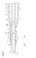
図8に示すカテーテル組立体10aにおいて、カテーテル12aには、密着部30に開口する側孔60が設けられている。カテーテル12aは、側孔60が設けられていること以外は、カテーテル12(図1等)と同様に構成されている。側孔60は、周方向に間隔を置いて複数設けられている。側孔60は、密着部30の最基端位置よりも先端側に設けられている。側孔60は、カテーテル12aの内周面から外周面まで貫通している。側孔60は、カテーテル本体34と柔軟部38の両方を貫通している。カ テ ー テ ル In the
他の態様において、側孔60は、周方向に1つだけ設けられてもよい。側孔60は、カテーテル12aの軸方向に間隔を置いて複数設けられてもよい。側孔60は、カテーテル本体34と柔軟部38のいずれか一方のみを貫通していてもよい。カテーテル12aの内周面において、側孔60は、カテーテル本体34と柔軟部38の両方に跨って設けられていてもよい。側孔60は、カテーテル12aの径方向に対して傾斜していてもよい。また、カテーテル12aにおける導入路44として図3のような溝部44Bが採用される場合は、カテーテル12aの側孔60は溝部44Bと周方向に位置がずれているのが好ましい。In another embodiment, only one
上記のように構成されたカテーテル組立体10aの使用においては、図9Aに示すように、カテーテル組立体10aの血管50への穿刺に伴い、内針16のルーメン及び導入路44を介して、フラッシュバック流路32に血液が流入する。カテーテル12aには側孔60が設けられているが、側孔60は、密着部30にて開口し、フラッシュバック流路32には開口していないため、血液がフラッシュバック流路32から側孔60を介してカテーテル12aの外側に漏れ出ることはない。In the use of the
また図8に示すカテーテル組立体10aにおいて、カテーテル12aには、混在領域40Cに開口する側孔60が設けられている。混在領域40Cにはカテーテル本体34が含まれているため、柔軟部単体領域40Bよりも比較的硬い。In the
上記のような構成とすることで、柔軟部単体領域40Bに側孔60を設けた場合とくらべて、吸引時のカテーテル12aの変形を抑制し、カテーテル12aの閉塞を防止することができる。With the above-described configuration, deformation of the
図9Bに示すように、カテーテル12aから内針16を抜去した後、カテーテル12aに造影剤等の液体Lを高圧で血管内に導入するとき、液体Lは、カテーテル12aの先端開口12opだけでなく、側孔60からも噴出する。このため、液体Lの噴出の圧力が分散することで、高い圧力が局所的に血管50に作用することが防止され、血管50への影響を減少させることができる。また、液体Lの噴出の反作用でカテーテル12aの位置がずれることを防止することができる。As shown in FIG. 9B, when the liquid L such as a contrast medium is introduced into the blood vessel at a high pressure after the
なお、図8に示した構成に関連して、以下の発明(カテーテル組立体)が把握できる。The following invention (catheter assembly) can be grasped in relation to the configuration shown in FIG.
カテーテルと、
前記カテーテルに挿通された内針と、を備え、
前記カテーテルは、
カテーテル本体と、前記カテーテル本体の先端部に設けられ、前記カテーテルの最先端部を含み、前記カテーテル本体よりも柔軟な柔軟部と、を有し、
前記カテーテルは、内周面の少なくとも一部が前記内針の外周面と密着した密着部を有し、前記密着部では、前記柔軟部と前記カテーテル本体の両方が前記内針と密着しており、
前記カテーテルには、前記密着部に開口する側孔が設けられており、
前記カテーテルと前記内針との間には、フラッシュバック確認用の流路が形成され、
前記内針には、前記流路と連通し、前記流路に血液を導入するための導入路が設けられている、カテーテル組立体。A catheter,
An inner needle inserted through the catheter,
The catheter is
A catheter body, provided at the distal end of the catheter body, including the distal end of the catheter, having a flexible portion that is more flexible than the catheter body,
The catheter has a contact portion in which at least a part of the inner peripheral surface is in close contact with the outer peripheral surface of the inner needle, and in the contact portion, both the flexible portion and the catheter body are in close contact with the inner needle. ,
The catheter is provided with a side hole that opens to the close contact portion,
A flow path for flashback confirmation is formed between the catheter and the inner needle,
The catheter assembly, wherein the inner needle is provided with an introduction passage communicating with the flow passage and introducing blood into the flow passage.
なお、本実施形態において、図8に示すカテーテル組立体10aにおけるカテーテル本体34を構成する第1の材料と柔軟部38を構成する第2の材料の物性は、前記した組み合わせに限らない。例えば、第2の材料における25℃と37℃の柔軟性の変化が、第1の材料における25℃と37℃の柔軟性の変化と同じ又は大きくてもよい。In the present embodiment, the physical properties of the first material forming the
本発明は上述した実施形態に限定されるものではなく、本発明の要旨を逸脱しない範囲において、種々の改変が可能である。The present invention is not limited to the above-described embodiment, and various modifications can be made without departing from the gist of the present invention.
Claims (4)
Translated fromJapanese前記カテーテルに挿通された内針と、を備え、
前記カテーテルは、
カテーテル本体と、前記カテーテル本体の先端部に設けられ、前記カテーテルの最先端部を含み、前記カテーテル本体よりも柔軟な柔軟部と、を有し、
前記カテーテル本体は、第1の材料から構成され、
前記柔軟部は、第2の材料から構成され、
前記第2の材料の25℃と37℃との間の柔軟性の変化は、前記第1の材料の25℃と37℃との間の柔軟性の変化よりも小さい、カテーテル組立体。A catheter,
An inner needle inserted through the catheter,
The catheter is
A catheter body, provided at the distal end of the catheter body, including the distal end of the catheter, having a flexible portion that is more flexible than the catheter body,
The catheter body is made of a first material,
The flexible portion is made of a second material,
The catheter assembly, wherein the change in flexibility between 25 ° C and 37 ° C of the second material is less than the change in flexibility between 25 ° C and 37 ° C of the first material.
前記カテーテルと前記内針との間には、フラッシュバック確認用の流路が形成され、
前記内針には、前記流路と連通し、前記流路に血液を導入するための導入路が設けられ、
前記導入路の基端は、前記柔軟部のうち前記カテーテル本体の最先端部よりも先端側に存在する部分の軸方向中央位置よりも基端側に設けられている、カテーテル組立体。The catheter assembly according to claim 1,
A flow path for flashback confirmation is formed between the catheter and the inner needle,
The inner needle communicates with the flow path, and an introduction path for introducing blood into the flow path is provided.
A catheter assembly, wherein a proximal end of the introduction path is provided on a proximal end side of an axial center position of a portion of the flexible portion that is located on a distal end side of a distal end portion of the catheter body.
前記カテーテルは、内周面の少なくとも一部が前記内針の外周面と密着した密着部を有し、
前記密着部では、前記柔軟部と前記カテーテル本体の両方が前記内針と密着している、カテーテル組立体。The catheter assembly according to claim 1,
The catheter has a contact portion in which at least a part of the inner peripheral surface is in close contact with the outer peripheral surface of the inner needle,
The catheter assembly, wherein at the contact portion, both the flexible portion and the catheter body are in close contact with the inner needle.
前記カテーテルには、前記密着部に開口する側孔が設けられている、カテーテル組立体。The catheter assembly according to claim 3,
The catheter assembly, wherein the catheter has a side hole that opens to the close contact portion.
Priority Applications (2)
| Application Number | Priority Date | Filing Date | Title |
|---|---|---|---|
| JP2020546795AJP7467350B2 (en) | 2018-09-12 | 2019-08-20 | Catheter Assembly |
| US17/193,228US12036372B2 (en) | 2018-09-12 | 2021-03-05 | Catheter assembly |
Applications Claiming Priority (2)
| Application Number | Priority Date | Filing Date | Title |
|---|---|---|---|
| JP2018-170580 | 2018-09-12 | ||
| JP2018170580 | 2018-09-12 |
Related Child Applications (1)
| Application Number | Title | Priority Date | Filing Date |
|---|---|---|---|
| US17/193,228ContinuationUS12036372B2 (en) | 2018-09-12 | 2021-03-05 | Catheter assembly |
Publications (1)
| Publication Number | Publication Date |
|---|---|
| WO2020054331A1true WO2020054331A1 (en) | 2020-03-19 |
Family
ID=69777271
Family Applications (1)
| Application Number | Title | Priority Date | Filing Date |
|---|---|---|---|
| PCT/JP2019/032403CeasedWO2020054331A1 (en) | 2018-09-12 | 2019-08-20 | Catheter assembly |
Country Status (3)
| Country | Link |
|---|---|
| US (1) | US12036372B2 (en) |
| JP (1) | JP7467350B2 (en) |
| WO (1) | WO2020054331A1 (en) |
Families Citing this family (1)
| Publication number | Priority date | Publication date | Assignee | Title |
|---|---|---|---|---|
| US20240181210A1 (en)* | 2022-12-06 | 2024-06-06 | Bard Access Systems, Inc. | Catheter Tips for Rapidly Insertable Central Catheters and Methods Thereof |
Citations (5)
| Publication number | Priority date | Publication date | Assignee | Title |
|---|---|---|---|---|
| JPH02191466A (en)* | 1988-10-13 | 1990-07-27 | Terumo Corp | Preparation of catheter |
| JPH04108554U (en)* | 1991-02-28 | 1992-09-18 | 三菱電線工業株式会社 | Catheter with a soft tip at the tip |
| US6893427B1 (en)* | 2000-03-23 | 2005-05-17 | Vascon, Llc | Catheter with thermoresponsive distal tip portion |
| JP2011251081A (en)* | 2010-06-04 | 2011-12-15 | Jms Co Ltd | Indwelling needle device |
| US20160310704A1 (en)* | 2013-12-04 | 2016-10-27 | B. Braun Melsungen Ag | Needle assembly with sealed notch and related methods |
Family Cites Families (32)
| Publication number | Priority date | Publication date | Assignee | Title |
|---|---|---|---|---|
| US4402684A (en)* | 1981-09-16 | 1983-09-06 | The Kendall Company | Cannula with soft tip |
| US4563181A (en)* | 1983-02-18 | 1986-01-07 | Mallinckrodt, Inc. | Fused flexible tip catheter |
| US5017259A (en)* | 1988-10-13 | 1991-05-21 | Terumo Kabushiki Kaisha | Preparation of catheter including bonding and then thermoforming |
| US5234416A (en)* | 1991-06-06 | 1993-08-10 | Advanced Cardiovascular Systems, Inc. | Intravascular catheter with a nontraumatic distal tip |
| GB9317539D0 (en)* | 1993-08-24 | 1993-10-06 | Shiu Man F | Catheter |
| JPH08112343A (en)* | 1994-10-18 | 1996-05-07 | Unitika Ltd | In-vivo indwelling catheter |
| US6325790B1 (en)* | 1995-04-11 | 2001-12-04 | Cordis Corporation | Soft tip catheter |
| US5997526A (en)* | 1996-03-25 | 1999-12-07 | The Uab Research Foundation | Shape memory catheter |
| NL1003226C2 (en)* | 1996-05-29 | 1997-12-03 | Cordis Europ | Suction catheter with preformed end section. |
| US5762630A (en)* | 1996-12-23 | 1998-06-09 | Johnson & Johnson Medical, Inc. | Thermally softening stylet |
| US5957966A (en)* | 1998-02-18 | 1999-09-28 | Intermedics Inc. | Implantable cardiac lead with multiple shape memory polymer structures |
| US6002969A (en)* | 1998-08-05 | 1999-12-14 | Intermedics Inc. | Cardiac lead with shape-memory structure |
| ATE276789T1 (en)* | 1998-10-13 | 2004-10-15 | Terumo Corp | SELF-HOLDING NEEDLE ASSEMBLY AND VALVE ELEMENT USED THEREIN |
| US6245053B1 (en)* | 1998-11-09 | 2001-06-12 | Medtronic, Inc. | Soft tip guiding catheter and method of fabrication |
| WO2000066211A1 (en)* | 1999-04-30 | 2000-11-09 | Usaminanotechnology, Inc. | Catheter and guide wire |
| DE19962985C1 (en)* | 1999-12-24 | 2000-12-28 | Vbm Medizintechnik Gmbh | Transpharyngeal tube comprises an end unit made of a material which is softer than the material of the tube shaft |
| US6695832B2 (en)* | 2000-06-01 | 2004-02-24 | Twincath, Llc | Multilumen catheter and methods for making the catheter |
| US6719749B1 (en)* | 2000-06-01 | 2004-04-13 | Medical Components, Inc. | Multilumen catheter assembly and methods for making and inserting the same |
| JP3830752B2 (en)* | 2000-11-14 | 2006-10-11 | 帝人テクノプロダクツ株式会社 | Performance evaluation equipment for fire protection clothing |
| JP2002143319A (en) | 2000-11-14 | 2002-05-21 | Ci Medeikku:Kk | Assembly of an introducer catheter and a diagnostic treatment catheter with a drug release function |
| JP2008043445A (en) | 2006-08-11 | 2008-02-28 | Medikit Kk | Catheter, hollow needle and dwelling needle assembly |
| EP2476384B1 (en)* | 2006-11-22 | 2015-11-04 | Applied Medical Resources Corporation | Trocar cannula with atraumatic tip |
| JP5317566B2 (en)* | 2008-07-30 | 2013-10-16 | テルモ株式会社 | Catheter assembly |
| JP6007175B2 (en)* | 2011-06-29 | 2016-10-12 | テルモ株式会社 | Introducer sheath |
| CN107252518B (en)* | 2012-11-13 | 2020-04-14 | 泰尔茂株式会社 | Catheter tube |
| JP2015181485A (en)* | 2014-03-20 | 2015-10-22 | テルモ株式会社 | catheter assembly |
| JPWO2015146408A1 (en)* | 2014-03-28 | 2017-04-13 | テルモ株式会社 | Catheter assembly and internal catheter |
| US20160129221A1 (en)* | 2014-11-07 | 2016-05-12 | Boston Scientific Scimed, Inc. | Medical device having an atraumatic distal tip |
| EP4032578A1 (en)* | 2016-07-13 | 2022-07-27 | Perfuze Limited | High flexibility, kink resistant catheter shaft |
| CN106236213A (en)* | 2016-09-12 | 2016-12-21 | 张小明 | Fallopian tube interventional therapy device |
| US20230047163A1 (en)* | 2017-08-09 | 2023-02-16 | Accurate Medical Therapeutics Ltd. | Microcatheter |
| CN108057167A (en)* | 2017-11-30 | 2018-05-22 | 封建立 | A kind of soft head end ureter guide sheath |
- 2019
- 2019-08-20WOPCT/JP2019/032403patent/WO2020054331A1/ennot_activeCeased
- 2019-08-20JPJP2020546795Apatent/JP7467350B2/enactiveActive
- 2021
- 2021-03-05USUS17/193,228patent/US12036372B2/enactiveActive
Patent Citations (5)
| Publication number | Priority date | Publication date | Assignee | Title |
|---|---|---|---|---|
| JPH02191466A (en)* | 1988-10-13 | 1990-07-27 | Terumo Corp | Preparation of catheter |
| JPH04108554U (en)* | 1991-02-28 | 1992-09-18 | 三菱電線工業株式会社 | Catheter with a soft tip at the tip |
| US6893427B1 (en)* | 2000-03-23 | 2005-05-17 | Vascon, Llc | Catheter with thermoresponsive distal tip portion |
| JP2011251081A (en)* | 2010-06-04 | 2011-12-15 | Jms Co Ltd | Indwelling needle device |
| US20160310704A1 (en)* | 2013-12-04 | 2016-10-27 | B. Braun Melsungen Ag | Needle assembly with sealed notch and related methods |
Also Published As
| Publication number | Publication date |
|---|---|
| US12036372B2 (en) | 2024-07-16 |
| JPWO2020054331A1 (en) | 2021-08-30 |
| JP7467350B2 (en) | 2024-04-15 |
| US20210187245A1 (en) | 2021-06-24 |
Similar Documents
| Publication | Publication Date | Title |
|---|---|---|
| US11904115B2 (en) | Catheter assembly | |
| US11819674B2 (en) | Catheter assembly | |
| CN208852216U (en) | Introducer sheaths and dilation components | |
| US20240024622A1 (en) | Catheter assembly | |
| JPWO2018181195A1 (en) | Catheter assembly | |
| JP6797612B2 (en) | Introducer sheath | |
| US20210220618A1 (en) | Catheter assembly | |
| US12036372B2 (en) | Catheter assembly | |
| WO2013140967A1 (en) | Introducer sheath | |
| US20210196925A1 (en) | Catheter assembly | |
| WO2016152377A1 (en) | Catheter assembly | |
| US20220203073A1 (en) | Catheter assembly | |
| JP2018143268A (en) | Catheter assembly | |
| WO2024203128A1 (en) | Auxiliary tool for catheter assembly and puncture device | |
| WO2013140968A1 (en) | Introducer sheath | |
| WO2021166960A1 (en) | Catheter assembly | |
| WO2021106937A1 (en) | Catheter assembly |
Legal Events
| Date | Code | Title | Description |
|---|---|---|---|
| 121 | Ep: the epo has been informed by wipo that ep was designated in this application | Ref document number:19859800 Country of ref document:EP Kind code of ref document:A1 | |
| ENP | Entry into the national phase | Ref document number:2020546795 Country of ref document:JP Kind code of ref document:A | |
| NENP | Non-entry into the national phase | Ref country code:DE | |
| 122 | Ep: pct application non-entry in european phase | Ref document number:19859800 Country of ref document:EP Kind code of ref document:A1 |