WO2020052016A1 - Defect closure device assembly and intervention method therefor - Google Patents
Defect closure device assembly and intervention method thereforDownload PDFInfo
- Publication number
- WO2020052016A1 WO2020052016A1PCT/CN2018/112649CN2018112649WWO2020052016A1WO 2020052016 A1WO2020052016 A1WO 2020052016A1CN 2018112649 WCN2018112649 WCN 2018112649WWO 2020052016 A1WO2020052016 A1WO 2020052016A1
- Authority
- WO
- WIPO (PCT)
- Prior art keywords
- channel
- puncture needle
- rod body
- defect
- head
- Prior art date
- Legal status (The legal status is an assumption and is not a legal conclusion. Google has not performed a legal analysis and makes no representation as to the accuracy of the status listed.)
- Ceased
Links
Images


Classifications
- A—HUMAN NECESSITIES
- A61—MEDICAL OR VETERINARY SCIENCE; HYGIENE
- A61B—DIAGNOSIS; SURGERY; IDENTIFICATION
- A61B17/00—Surgical instruments, devices or methods
- A61B17/0057—Implements for plugging an opening in the wall of a hollow or tubular organ, e.g. for sealing a vessel puncture or closing a cardiac septal defect
- A61B2017/00575—Implements for plugging an opening in the wall of a hollow or tubular organ, e.g. for sealing a vessel puncture or closing a cardiac septal defect for closure at remote site, e.g. closing atrial septum defects
- A61B2017/00592—Elastic or resilient implements
Definitions
- the present inventionrelates to the technical field of biomedical devices, and in particular, to a defect obturator assembly and an intervention method thereof, which are mainly due to the treatment of unobstructed oval foramen and atrial septal defect.
- Foramen ovale closureis an earlier treatment for interventional congenital heart disease. At present, it has accumulated mature experience in China.
- an umbrella-shaped metal occluderis usually used to clamp the tissue around the defect, so as to achieve occlusion of the defect site.
- the occluderis a large foreign body, which not only has the risk of falling off, but also forms blood clots after implantation. Patients need to take aspirin for at least half a year. Even so, some patients have poor endothelialization and continue to produce blood clots.
- the metal occluderwill remain in the patient's body for a long time, and there is a risk of abrading the surrounding tissue in the long term, causing complications such as cardiac perforation.
- the main purpose of the present inventionis to provide a defect obturator assembly and an intervention method thereof, in order to solve the problem that the prior art interventional occlusion requires implantation of a metal occluder and persists for a long time, which will bring a lot of risks.
- a defect closure devicecomprising a closure device and a puncture needle.
- the closure deviceincludes a rod body, the rod body has a first channel and a second channel inside, and the head of the rod body may be Bend, the inlet of the first channel and the inlet of the second channel are located at the tail of the rod body, the outlet of the first channel is located inside when the head of the rod is bent, and the outlet of the second channel is located below the outlet of the first channel;
- the lead structurecan be movably arranged at the exit of the first channel;
- the sutureis an absorbable or non-absorbable suture, and the suture passes from the entrance of the first channel into the first channel and is connected with the lead structure
- the puncture needlepasses through the second channel, the tissue around the organ defect hole and is connected to the lead structure.
- a bending sectionis provided at a position near the exit of the first passage and a position near the exit of the second passage, so that when the head of the rod body is bent, the exit of the second passage can be aligned with the lead structure.
- the lead structureis a buckle
- the bucklehas a groove
- a barbis provided on the inner wall of the groove.
- the longitudinal section of the barbis triangular, the head of the puncture needle has a pointed tip, and the head of the puncture needle protrudes from the rest of the puncture needle along its radial direction.
- both the head of the puncture needle and the lead structurehave a metal part, and a bubble structure is provided in the metal part.
- the bubble structureenables the metal part to be clearly developed under ultrasound, so that it can be positioned under ultrasound guidance without using radiation.
- the lead structureis cloth filled at the exit of the first channel, and the head of the puncture needle has barbs.
- the barbshook the cloth so that the puncture needle can move the cloth together.
- the lead structureis a first magnet
- the head of the puncture needlehas a second magnet.
- the defect closer assemblyfurther includes a third magnet and a metal part capable of being attracted by the third magnet, one of the third magnet and the metal part forms a lead structure, and the other of the third magnet and the metal part It is arranged on the head of the puncture needle.
- the third magnetattracts the metal part, so that the puncture needle can move the lead structure together.
- the rod bodyincludes a rod body and a bent rod rotatably disposed on the rod body, the bent rod forms a head of the rod body, and an outlet of the second channel is located on a side wall of the rod body.
- the first channelincludes a main channel section and a sub channel section.
- the main channel sectionis disposed in the rod body
- the sub channel sectionis disposed in the bending rod
- the diameter of the end of the sub channel section near the rod bodyis smaller than that of the main channel section near the bend. The diameter of one end of the folding rod, during the rotation of the bending rod, the auxiliary channel section rotates with the bending rod, and the auxiliary channel section and the main channel section are always connected.
- the rod bodyfurther includes a connection structure connected between the rod body and the bending rod.
- the connection structurecan be rotatably connected with the rod body and the bending rod.
- the connection structureincludes at least one connecting rod. When the connecting rod has multiple sections, each The adjacent two sections of the connecting rod can be rotatably connected.
- the rod bodyalso has a third channel inside, the inlet of the third channel is located at the tail of the rod body, the outlet of the third channel is located at the head of the rod body, and the third channel is used to pass through the guide wire so that the closure can be guided along the guide.
- the silkis fed into the body and inserted into an organ defect hole.
- an intervention method for a defect obturator assemblywhich in turn includes the following steps:
- Puncture the femoral veinsend the catheter and guide wire into the body, and enter the organ defect hole, exit the catheter, retain the guide wire; thread the guide wire into the third channel inside the rod body of the closer, and the closer is guided along the guide wire.
- withdraw the guide wirebend the bending rod of the rod to the side of the organ defect hole, pass the puncture needle through the second channel, pierce the tissue around the organ defect hole, and bend
- the head of the rodis first bent to one side of the organ defect hole, and then the puncture needle is passed through the second channel to pierce the tissue around the organ defect hole. Connect with the lead structure, and then withdraw the puncture needle.
- the puncture needledrives the lead structure to move together to make the suture pass through the tissue around the organ defect hole along the path of the puncture needle withdraw.
- the head of the rodwas straightened and the retractor was withdrawn, and the suture thread was put on the tissue on the side of the organ defect hole.
- Insert a new suture into the obturator or use a new obturatorrepeat the above operation, and thread the suture over the tissue on the other side of the organ defect hole.
- the knots on the two sides of the organ defect holeare tied and tied by a knotter, so that the organ defect hole is closed.
- the above operationcan be repeated multiple times, after multiple sutures are inserted, and then knotted, the defect can be completely closed.
- FIG. 1is a schematic cross-sectional view of a closer of a first embodiment of a defect closer assembly according to the present invention
- FIG. 2shows an enlarged schematic view of A of the closer of FIG. 1;
- FIG. 3is a schematic cross-sectional view of the bender of the closer of FIG. 1 when it is bent;
- Figure 4shows a schematic sectional view of the closure of Figure 3 with the puncture needle
- FIG. 5shows a schematic structural diagram when the atrial septal defect hole (oval hole) is repaired by using the defect closer component of FIG. 1;
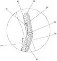
- FIG. 6shows an enlarged schematic view at B of the defect closer assembly and atrial septal defect hole of FIG. 5;
- FIG. 7is a schematic structural diagram of a knotter of the defect closer assembly of FIG. 1.
- the defect closure device of the first embodimentis used for closing and repairing an oval hole (or atrial septal defect).
- the defect closure device described aboveincludes a closure device and a puncture needle 10.
- the closerincludes a rod body 20, a lead structure, and a suture 30.
- the rod body 20has a first channel 21 and a second channel 22 inside.
- the head of the rod body 20can be bent.
- the inlet of the first channel 21 and the inlet of the second channel 22are both located at the tail of the rod body 20.
- the outlet of the first channel 21is located on a side wall of the head of the rod body 20, and the outlet of the first channel 21 is located on the inner side when the head of the rod body 20 is bent.
- the exit of the second passage 22is located below the exit of the first passage 21.
- the lead structureis movably disposed at the exit of the first channel 21.
- the suture thread 30penetrates into the first channel 21 from the entrance of the first channel 21 and is connected to the lead structure.
- the rod body 20also has a third channel 25 inside.
- the entrance of the third channel 25is located at the tail of the rod body 20.
- the exit of the third channel 25is located at the head of the rod body 20.
- the third channel 25is used to pass through the guide wire so that the obturator can be introduced into the body along the guide wire and inserted into the organ defect hole 50.
- the femoral veinis punctured, the catheter and the guide wire are introduced into the body, and the organ and the guide wire are passed into the organ defect hole 50.
- the catheteris withdrawn and the guide wire is retained.
- the guide wireis then inserted into the third channel 25, and the obturator is sent into the body along the guide wire and inserted into the organ defect hole 50, and exits the guide wire.
- the head of the rod body 20is first bent toward one side of the organ defect hole 50, and then the puncture needle 10 is passed through the second channel 22 to pierce the tissue around the organ defect hole 50 and Connect to the lead structure and then withdraw the puncture needle 10.
- the puncture needle 10When the puncture needle 10 is withdrawn, the puncture needle 10 drives the lead structure to move together, so that the suture 30 passes through the tissue around the organ defect hole 50 along the path with which the puncture needle 10 exits. Thereafter, the head of the rod body 20 is straightened, and the guide wire is re-entered along the third channel 25, the guide wire is retained in the body, the closure device is withdrawn, and the suture thread 30 is put on the tissue of one side of the organ defect hole 50. Insert the closure into a new suture 30 or use a new closure to insert the retained guide wire into the organ defect hole 50, repeat the above operation, and thread the suture 30 into the tissue on the other side of the organ defect hole 50 on.
- the sutures 30 on both sides of the organ defect hole 50are tied and tied by the knotter 60, so that the organ defect hole 50 (oval hole) is closed.
- the defect siteonly needs to be sutured through the suture 30, and no metal occluder needs to be implanted, thereby avoiding various risks brought by the metal occluder.
- the defect closure deviceis used to repair the oval hole.
- the defect closer componentcan be used for other types of defects, for example, it can be used to repair the atrial septal defect.
- the suture thread 30is an absorbable thread, and the thread is absorbed by the human body after endothelialization, so that there is no residual treatment of heart disease.
- the suture thread 30may be a non-absorbable thread.
- the first channel 21is located near its exit and the second channel 22 is near its exit.
- the outlet of the second channel 22can be aligned with the lead structure. That is, at this time, the center line of the exit of the second channel 22 and the center line of the lead structure are located on a straight line.
- the above structurecan prevent the puncture needle 10 from going out of the second channel 22 when it is pushed forward, and can accurately enter the lead structure of the first channel 21 without damaging other tissues.
- the lead structureis a buckle 40.
- the buckle 40has a groove, and an inner wall of the groove is provided with a barb 41.
- the barb 41extends one turn in the circumferential direction of the groove, and the barb 41 can be regarded as being formed by the inner wall of the groove protruding inward.
- the vertical cross section of the barb 41is triangular.
- the head of the puncture needle 10has a pointed tip (in this embodiment, the longitudinal section of the head of the puncture needle 10 also has a triangular shape, that is, the head of the puncture needle 10 has a triangular pyramid shape), Its radial direction projects beyond the rest of the puncture needle 10.
- the triangular tapered surface of the head of the puncture needle 10contacts the slant surface of the barb 41. After the head of the puncture needle 10 is fully extended, the bottom surface of the barb 41 is stuck. The bottom surface of the head of the puncture needle 10 is held, so that the head of the puncture needle 10 is hooked, so that the puncture needle 10 can drive the buckle 40 to move together.
- the lead structureis set as a buckle 40 with a barb 41, and the head of the puncture needle 10 is hooked by the barb 41, the structure is simple, and the connection between the lead structure and the puncture needle 10 can be made more reliable.
- the barb 41is arranged in a circle to further ensure the connection reliability and effectively prevent the buckle 40 and the head of the puncture needle 10 from falling off.
- the head of the puncture needle 10protrudes from the rest of the puncture needle 10 in the radial direction, so as to be able to match the bottom surface of the protruding portion of the puncture needle 10 with the barb 41 to further ensure For connection reliability.
- the head of the puncture needle 10has a triangular cone shape, and the longitudinal cross-section of the barb 41 is triangular.
- the triangular cone surface of the puncture needle 10 and the inclined surface of the barb 41can slide in contact with each other, and play a guiding role, thereby making the puncture The head of the needle 10 more easily protrudes into the U-shaped groove of the buckle 40.
- the lead structureis not limited to this.
- the lead structuremay be other structures that can be connected to the head of the puncture needle.
- the buckle 40has a cylindrical shape as a whole, and a groove is provided in the center thereof.
- the barb 41is arranged in a circle along the circumferential side wall of the groove.
- the structure of the buckle 40 and the number of the barb 41The shape and shape are not limited to this.
- the bucklemay be U-shaped as a whole, and barbs are provided on the inside, and the barbs are two symmetrically arranged.
- the barbsmay be bar-shaped barbs arranged obliquely, and the number of barbs may be only one or three or more, as long as they can hook the head of the puncture needle.
- the head of the puncture needle 10is not limited to a triangular pyramid shape. In other embodiments not shown in the figure, the shape of the head of the puncture needle may be similar to the combined shape of a triangular pyramid and a cylinder as a whole, as long as it can The head of the puncture needle protrudes beyond the rest of the puncture needle in its radial direction.
- both the head and the lead structure of the puncture needle 10have a metal portion, and a bubble structure 70 is provided in the metal portion.
- the metal partis clearly developed under ultrasound, so that it can be positioned under ultrasound guidance without using radiation.
- micro-bubblesare mixed in the metal, so that a bubble structure 70 is formed in the formed metal portion. This can enhance the echo of the head of the puncture needle 10 and the lead structure under ultrasound, and on the ultrasound image The bright spots appear as highlights, which can be used to locate and keep the puncture point away from important tissues.
- the entire head of the puncture needle 10 and the entire lead structureare made of a metal material, that is, the entire head of the puncture needle 10 and the entire lead structure are formed of metal. unit.
- the method of forming the metal portionis not limited to this. In other embodiments, the metal portion may be only a metal structure such as a metal block or a metal sheet provided on the head of the puncture needle or the lead structure.
- the rod body 20includes a rod body 23 and a bending rod 24 rotatably disposed on the rod body 23.
- the bending rod 24forms a head of the rod body 20.
- An outlet of the second channel 22is located on a side wall of the rod body 23.
- the bending rod 24is connected to the rod body 23 through a rotating shaft, and the bending rod 24 can be pivoted in a setting plane of the rod body 23.
- the length of the bending rod 24is 1 to 10 cm, and preferably 2 cm.
- the included angle between the closer rod main body 23 and the bending rod 24is 10 to 160 degrees, preferably 60 degrees.
- the closeralso includes a rotation control portion provided at the tail portion of the rod body 23, through which the rotation of the bending rod 24 can be controlled (the specific implementation manners are many in the prior art, for example, through the combination of a knob, a wire, and a rotating shaft Control the shaft rotation).
- the first channel 21includes a main channel section and a sub channel section.
- the main channel sectionis provided in the rod body 23, and the sub channel section is provided in the bending rod 24.
- the diameter of the end of the sub channel section near the rod body 23is smaller than that of the main channel section.
- the diameter of one end of the bending rod 24is
- the rotational connection between the bending rod 24 and the rod body 23is not limited to being connected through a rotating shaft.
- the bending rod and the rod bodycan be connected by other connection structures.
- the bending rod 24is not limited to pivot in the installation plane of the rod body 23, and in other embodiments, the bending rod can also rotate in any direction relative to the rod body.
- the specific form of the rod body 20is not limited to this.
- the rod bodymay also be an integral flexible rod, and the head thereof can be bent.
- the main difference between the defect closer device assembly (not shown in the figure) and the first embodimentis that the lead structure is cloth filled at the exit of the first channel, and the head of the puncture needle has barbs. When the head of the puncture needle is inserted into the fabric, the barb hooks the fabric so that the puncture needle can move the fabric together.
- other structures and working principles of the second embodimentare basically the same as those of the first embodiment, and details are not described herein again.
- the main difference between the defect closer assembly (not shown in the figure) and the first embodimentis that the lead structure is a first magnet, and the head of the puncture needle has a second magnet. When the head of the puncture needle is close to the first magnet, the first magnet and the second magnet are attracted and connected to each other, so that the puncture needle can move the first magnet together.
- other structures and working principles of the third embodimentare basically the same as those of the first embodiment, and details are not described herein again.
- the main difference between the defect closer assembly of the fourth embodiment (not shown) and the first embodimentlies in that the defect closer assembly further includes a third magnet and a metal part capable of being attracted by the third magnet, and the third magnet and the metal part One of them forms a lead structure, and the other of the third magnet and the metal part is provided on the head of the puncture needle. When the head of the puncture needle is close to the lead structure, the third magnet attracts the metal part, so that the puncture needle can move the lead structure together.
- other structures and working principles of the fourth embodimentare basically the same as those of the first embodiment, and details are not described herein again.
- the rod bodyfurther includes a connection structure connected between the rod body and the bending rod.
- the connecting structurecan be rotatably connected with the main body of the rod body and the bending rod.
- the connecting structureincludes one or more connecting rods. When the connecting rod has multiple sections, two adjacent sections of the connecting rods can be rotatably connected.
- the above-mentioned connection structurecan play a role similar to a joint, so that the rotation range of the bending rod is larger.
- other structures and working principles of the fifth embodimentare basically the same as those of the first embodiment, and details are not described herein again.
- the main difference between the defect closer device of the sixth embodiment and the first embodimentis that the defect closer device of the first embodiment is used for closing and repairing the oval hole, while the defect closer device of the sixth embodiment is compared with the existing occluder.
- the defect closer device of the first embodimentis used for closing and repairing the oval hole
- the defect closer device of the sixth embodimentis compared with the existing occluder.
- the sutureis transverse to the defect and divides the defect into two smaller defects, one of which is assisted by the suture.
- the lower perimeterhas sufficient edges and supporting force, and can be implanted into existing ordinary occluders. Because the umbrella plate of the ordinary occluder is 14mm larger than the waist diameter, the umbrella plate of the occluder can cover the atrial septal defect suture. The other part of the separation, the combined application of the two devices, can enable patients who have not been able to intervene in the past to receive minimally invasive treatment.
- the present applicationalso provides an intervention method for a defect obturator assembly, and an embodiment of the intervention method according to the application includes the following steps in order:
- Puncture the femoral veinsend the catheter and guide wire into the body, and enter the organ defect hole 50, exit the catheter, and retain the guide wire;
- the bending rod 24 of the rod body 20is bent toward one side of the organ defect hole 50, and the puncture needle 10 is passed through the second channel 22, piercing the tissue around the organ defect hole 50, and the lead structure inside the bending rod 24 connection;
- the puncture needle 10is withdrawn, and the lead structure is driven by the puncture needle 10 to move together, so that the absorbable suture 30 connected to the lead structure passes the tissue around the organ defect hole 50 along the path of the puncture needle 10 exit.
- the knots 60are used to tie and tie the sutures 30 on both sides of the organ defect hole 50 to close the organ defect hole 50.
- the head of the knotter 60has a hook portion 61.
- the free ends of the sutures 30 located on both sides of the organ defect hole 50are extended outside the body, and then The tied knot is pushed into the body and fastened by the hook portion 61 of the knotter 60.
- the specific form of the knotter 60is not limited to this. In other embodiments not shown in the figure, the knotter may also have a thread trimming function.
Landscapes
- Health & Medical Sciences (AREA)
- Surgery (AREA)
- Life Sciences & Earth Sciences (AREA)
- Biomedical Technology (AREA)
- Nuclear Medicine, Radiotherapy & Molecular Imaging (AREA)
- Engineering & Computer Science (AREA)
- Cardiology (AREA)
- Heart & Thoracic Surgery (AREA)
- Medical Informatics (AREA)
- Molecular Biology (AREA)
- Animal Behavior & Ethology (AREA)
- General Health & Medical Sciences (AREA)
- Public Health (AREA)
- Veterinary Medicine (AREA)
- Surgical Instruments (AREA)
Abstract
Description
Translated fromChinese本发明涉及生物医学器械技术领域,具体而言,涉及一种缺损闭合器组件及其介入方法,主要由于治疗卵圆孔未闭及房间隔缺损。The present invention relates to the technical field of biomedical devices, and in particular, to a defect obturator assembly and an intervention method thereof, which are mainly due to the treatment of unobstructed oval foramen and atrial septal defect.
卵圆孔封堵术,是较早应用的介入性先天性心脏病的治疗措施,目前国内已累积了较为成熟的经验。在现有的卵圆孔封堵术中,通常使用伞状金属封堵器夹紧缺损周围的组织,从而实现对缺损部位的封堵。然而,封堵器为大型异物,不但有脱落风险,而且植入体内后会形成血栓,患者需要服用至少半年的阿司匹林,即使如此,仍有部分患者内皮化不良,持续产生血栓。另一方面,金属封堵器将终身存留于患者体内,远期有磨蚀周围组织,造成心脏穿孔等并发症的风险。Foramen ovale closure is an earlier treatment for interventional congenital heart disease. At present, it has accumulated mature experience in China. In the existing oval hole occlusion technique, an umbrella-shaped metal occluder is usually used to clamp the tissue around the defect, so as to achieve occlusion of the defect site. However, the occluder is a large foreign body, which not only has the risk of falling off, but also forms blood clots after implantation. Patients need to take aspirin for at least half a year. Even so, some patients have poor endothelialization and continue to produce blood clots. On the other hand, the metal occluder will remain in the patient's body for a long time, and there is a risk of abrading the surrounding tissue in the long term, causing complications such as cardiac perforation.
发明内容Summary of the Invention
本发明的主要目的在于提供一种缺损闭合器组件及其介入方法,以解决现有技术中的介入封堵术需要植入金属封堵器且长期存留,这样会带来诸多风险的问题。The main purpose of the present invention is to provide a defect obturator assembly and an intervention method thereof, in order to solve the problem that the prior art interventional occlusion requires implantation of a metal occluder and persists for a long time, which will bring a lot of risks.
为了实现上述目的,根据本发明的一个方面,提供了一种缺损闭合器组件,包括闭合器及穿刺针,闭合器包括:杆体,杆体内部具有第一通道及第二通道,杆体的头部可弯折,第一通道的进口和第二通道的进口均位于杆体的尾部,第一通道的出口位于杆体的头部弯折时 的内侧,第二通道的出口位于第一通道的出口的下方;引线结构,可活动地设置在第一通道的出口处;缝合线,缝合线为可吸收缝合线或不可吸收缝合线,缝合线从第一通道的进口穿入第一通道内并与引线结构连接,当闭合器插入器官缺损孔后,杆体的头部弯折,将穿刺针依次穿过第二通道、器官缺损孔周围的组织并与引线结构连接,当穿刺针退出时,穿刺针带动引线结构共同移动,以使缝合线沿着穿刺针退出的路径穿过器官缺损孔周围的组织。In order to achieve the above object, according to an aspect of the present invention, there is provided a defect closure device comprising a closure device and a puncture needle. The closure device includes a rod body, the rod body has a first channel and a second channel inside, and the head of the rod body may be Bend, the inlet of the first channel and the inlet of the second channel are located at the tail of the rod body, the outlet of the first channel is located inside when the head of the rod is bent, and the outlet of the second channel is located below the outlet of the first channel; The lead structure can be movably arranged at the exit of the first channel; the suture is an absorbable or non-absorbable suture, and the suture passes from the entrance of the first channel into the first channel and is connected with the lead structure After the obturator is inserted into the organ defect hole, the head of the rod is bent, and the puncture needle passes through the second channel, the tissue around the organ defect hole and is connected to the lead structure. When the puncture needle is withdrawn, the puncture needle drives the lead structure. Move together so that the suture passes through the tissue around the organ defect hole along the path that the puncture needle exits.
进一步地,第一通道靠近其出口的位置以及第二通道靠近其出口的位置均设有弯曲段,以使杆体的头部弯折时第二通道的出口能够对准引线结构。Further, a bending section is provided at a position near the exit of the first passage and a position near the exit of the second passage, so that when the head of the rod body is bent, the exit of the second passage can be aligned with the lead structure.
进一步地,引线结构为卡扣,卡扣上具有凹槽,凹槽的内壁上设置有倒钩,当穿刺针的头部伸入凹槽内,倒钩钩住穿刺针的头部以使穿刺针能够带动卡扣共同移动。Further, the lead structure is a buckle, the buckle has a groove, and a barb is provided on the inner wall of the groove. When the head of the puncture needle extends into the groove, the barb hooks the head of the puncture needle to make puncture The needle can move the buckle together.
进一步地,倒钩的纵截面呈三角形,穿刺针的头部具有尖头,穿刺针的头部沿其径向方向凸出于穿刺针的其余部分。Further, the longitudinal section of the barb is triangular, the head of the puncture needle has a pointed tip, and the head of the puncture needle protrudes from the rest of the puncture needle along its radial direction.
进一步地,穿刺针的头部及引线结构均具有金属部,金属部内设置有气泡结构,气泡结构能使金属部在超声下清晰显影,从而可以在超声引导下进行定位而不需要使用放射线。Further, both the head of the puncture needle and the lead structure have a metal part, and a bubble structure is provided in the metal part. The bubble structure enables the metal part to be clearly developed under ultrasound, so that it can be positioned under ultrasound guidance without using radiation.
进一步地,引线结构为填充在第一通道的出口处的布料,穿刺针的头部具有倒刺,当穿刺针的头部插入布料后,倒刺钩住布料以使穿刺针能够带动布料共同移动。Further, the lead structure is cloth filled at the exit of the first channel, and the head of the puncture needle has barbs. When the head of the puncture needle is inserted into the cloth, the barbs hook the cloth so that the puncture needle can move the cloth together. .
进一步地,引线结构为第一磁铁,穿刺针的头部具有第二磁铁,当穿刺针的头部靠近第一磁铁时,第一磁铁与第二磁铁相互吸引连接,以使穿刺针能够带动第一磁铁共同移动;或者,缺损闭合器组件还包括第三磁铁及能够被第三磁铁吸附的金属部,第三磁铁和金属部中的一个形成引线结构,第三磁铁和金属部中的另一个设置在穿刺针的头部,当穿刺针的头部靠近引线结构时,第三磁铁吸附住金属部,以使穿刺针能够带动引线结构共同移动。Further, the lead structure is a first magnet, and the head of the puncture needle has a second magnet. When the head of the puncture needle approaches the first magnet, the first magnet and the second magnet are attracted to each other so that the puncture needle can drive the first magnet. A magnet moves together; or, the defect closer assembly further includes a third magnet and a metal part capable of being attracted by the third magnet, one of the third magnet and the metal part forms a lead structure, and the other of the third magnet and the metal part It is arranged on the head of the puncture needle. When the head of the puncture needle is close to the lead structure, the third magnet attracts the metal part, so that the puncture needle can move the lead structure together.
进一步地,杆体包括杆体主体以及可转动地设置在杆体主体上的弯折杆,弯折杆形成杆体的头部,第二通道的出口位于杆体主体的侧壁上。Further, the rod body includes a rod body and a bent rod rotatably disposed on the rod body, the bent rod forms a head of the rod body, and an outlet of the second channel is located on a side wall of the rod body.
进一步地,第一通道包括主通道段及副通道段,主通道段设置在杆体主体内,副通道段设置在弯折杆内,副通道段靠近杆体主体的一端的直径小于主通道段靠近弯折杆的一端的直径,在弯折杆转动过程中,副通道段随着弯折杆转动,并且副通道段与主通道段始终连通。Further, the first channel includes a main channel section and a sub channel section. The main channel section is disposed in the rod body, the sub channel section is disposed in the bending rod, and the diameter of the end of the sub channel section near the rod body is smaller than that of the main channel section near the bend. The diameter of one end of the folding rod, during the rotation of the bending rod, the auxiliary channel section rotates with the bending rod, and the auxiliary channel section and the main channel section are always connected.
进一步地,杆体还包括连接在杆体主体和弯折杆之间的连接结构,连接结构与杆体主体、弯折杆均可转动连接,连接结构包括至少一段连接杆,当连接杆为多段时,各相邻的两段连接杆之间可转动连接。Further, the rod body further includes a connection structure connected between the rod body and the bending rod. The connection structure can be rotatably connected with the rod body and the bending rod. The connection structure includes at least one connecting rod. When the connecting rod has multiple sections, each The adjacent two sections of the connecting rod can be rotatably connected.
进一步地,杆体内部还具有第三通道,第三通道的进口位于杆体的尾部,第三通道的出口位于杆体的头部,第三通道用于穿过导丝,以使闭合器能够沿着导丝被送入体内并插入器官缺损孔。Further, the rod body also has a third channel inside, the inlet of the third channel is located at the tail of the rod body, the outlet of the third channel is located at the head of the rod body, and the third channel is used to pass through the guide wire so that the closure can be guided along the guide. The silk is fed into the body and inserted into an organ defect hole.
根据本发明的另一方面,提供了一种缺损闭合器组件的介入方法,依次包括以下步骤:According to another aspect of the present invention, there is provided an intervention method for a defect obturator assembly, which in turn includes the following steps:
穿刺股静脉,将导管和导丝送入体内,并通入器官缺损孔内,退出导管,保留导丝;将导丝穿入闭合器的杆体内部的第三通道,闭合器沿着导丝被送入体内并插入器官缺损孔,退出导丝;将杆体的弯折杆向器官缺损孔的一侧弯折,将穿刺针穿过第二通道、刺穿器官缺损孔周围的组织、并与弯折杆内侧的引线结构连接;退出穿刺针,穿刺针带动引线结构共同移动,以使与引线结构连接的缝合线沿着穿刺针退出的路径穿过器官缺损孔周围的组织,退出闭合器,缝合线穿在器官缺损孔的一侧组织上;重复上述步骤,将缝合线穿在器官缺损孔的另一侧组织上;通过打结器60将位于器官缺损孔的两侧的缝合线打结系紧,从而使器官缺损孔闭合。Puncture the femoral vein, send the catheter and guide wire into the body, and enter the organ defect hole, exit the catheter, retain the guide wire; thread the guide wire into the third channel inside the rod body of the closer, and the closer is guided along the guide wire. Into the body and insert the organ defect hole, withdraw the guide wire; bend the bending rod of the rod to the side of the organ defect hole, pass the puncture needle through the second channel, pierce the tissue around the organ defect hole, and bend The lead structure connection inside the folding rod; exit the puncture needle, the puncture needle drives the lead structure to move together, so that the suture connected to the lead structure passes the tissue around the organ defect hole along the path of the puncture needle exit, exits the closure, and sutures Thread the tissue on one side of the organ defect hole; repeat the above steps to thread the suture on the tissue on the other side of the organ defect hole; tie the sutures on both sides of the organ defect hole with a knotter 60 Tighten the organ defect hole to close.
应用本发明的技术方案,当闭合器插入器官缺损孔后,先将杆体的头部向器官缺损孔的一侧弯折,再将穿刺针穿过第二通道、刺穿器官缺损孔周围的组织并与引线结构连接,然后退出穿刺针。当穿刺针退出时,穿刺针带动引线结构共同移动,以使缝合线沿着穿刺针退出的路径穿过器官缺损孔周围的组织。此后,把杆体的头部伸直,退出闭合器,缝合线便穿在器官缺损孔的一侧组织上。将闭合器上装入新的缝合线或者使用新的闭合器,重复上述操作,将该缝合线穿在器官缺损孔的另一侧组织上。通过打结器将位于器官缺损孔的两侧的缝合线打结系紧,从而使器官缺损孔闭合。对于房间隔缺损,可以多次重复上述操作,打入多根缝合线后,再打结,能完全闭合缺损。采用上 述缺损闭合器组件,只需通过缝合线对缺损部位进行缝合,无需植入金属封堵器,从而避免了金属封堵器带来的各种风险。此外,还可以对不同尺寸的器官缺损孔进行修复闭合。With the technical solution of the present invention, after the closure is inserted into the organ defect hole, the head of the rod is first bent to one side of the organ defect hole, and then the puncture needle is passed through the second channel to pierce the tissue around the organ defect hole. Connect with the lead structure, and then withdraw the puncture needle. When the puncture needle is withdrawn, the puncture needle drives the lead structure to move together to make the suture pass through the tissue around the organ defect hole along the path of the puncture needle withdraw. After that, the head of the rod was straightened and the retractor was withdrawn, and the suture thread was put on the tissue on the side of the organ defect hole. Insert a new suture into the obturator or use a new obturator, repeat the above operation, and thread the suture over the tissue on the other side of the organ defect hole. The knots on the two sides of the organ defect hole are tied and tied by a knotter, so that the organ defect hole is closed. For atrial septal defect, the above operation can be repeated multiple times, after multiple sutures are inserted, and then knotted, the defect can be completely closed. With the above-mentioned defect obturator assembly, only the defect site needs to be sutured with sutures, and no metal occluder is implanted, thereby avoiding various risks brought by the metal occluder. In addition, repair and closure of organ defect holes of different sizes can also be performed.
构成本申请的一部分的说明书附图用来提供对本发明的进一步理解,本发明的示意性实施例及其说明用于解释本发明,并不构成对本发明的不当限定。在附图中:The accompanying drawings, which constitute a part of this application, are used to provide a further understanding of the present invention. The schematic embodiments of the present invention and the descriptions thereof are used to explain the present invention, and do not constitute an improper limitation on the present invention. In the drawings:
图1示出了根据本发明的缺损闭合器组件的实施例一的闭合器的剖视示意图;FIG. 1 is a schematic cross-sectional view of a closer of a first embodiment of a defect closer assembly according to the present invention; FIG.
图2示出了图1的闭合器的A处放大示意图;FIG. 2 shows an enlarged schematic view of A of the closer of FIG. 1; FIG.
图3示出了图1的闭合器的弯折杆弯折时的剖视示意图;3 is a schematic cross-sectional view of the bender of the closer of FIG. 1 when it is bent;
图4示出了图3的闭合器与穿刺针相配合的剖视示意图;Figure 4 shows a schematic sectional view of the closure of Figure 3 with the puncture needle;
图5示出了采用图1的缺损闭合器组件修复房间隔缺损孔(卵圆孔)时的结构示意图;FIG. 5 shows a schematic structural diagram when the atrial septal defect hole (oval hole) is repaired by using the defect closer component of FIG. 1; FIG.
图6示出了图5的缺损闭合器组件和房间隔缺损孔的B处放大示意图;以及FIG. 6 shows an enlarged schematic view at B of the defect closer assembly and atrial septal defect hole of FIG. 5; and
图7示出了图1的缺损闭合器组件的打结器的结构示意图。FIG. 7 is a schematic structural diagram of a knotter of the defect closer assembly of FIG. 1.
其中,上述附图包括以下附图标记:The above drawings include the following reference signs:
10、穿刺针;20、杆体;21、第一通道;22、第二通道;23、杆体主体;24、弯折杆;25、第三通道;30、缝合线;40、卡扣;41、倒钩;50、器官缺损孔;60、打结器;61、钩部;70、气泡结构。10, puncture needle; 20, rod body; 21, first channel; 22, second channel; 23, rod body; 24, bending rod; 25, third channel; 30, suture; 40, buckle; 41, Barbs; 50, organ defect holes; 60, knots; 61, hooks; 70, bubble structure.
需要说明的是,在不冲突的情况下,本申请中的实施例及实施例中的特征可以相互组合。下面将参考附图并结合实施例来详细说明本发明。It should be noted that, in the case of no conflict, the embodiments in the present application and the features in the embodiments can be combined with each other. The present invention will be described in detail below with reference to the drawings and embodiments.
如图1至图7所示,实施例一的缺损闭合器组件用于卵圆孔(或心脏房间隔缺损)的闭合修复。具体地,上述缺损闭合器组件包括闭合器及穿刺针10。闭合器包括杆体20、引线结构及缝合线30。其中,杆体20内部具有第一通道21及第二通道22。杆体20的头部可弯折。第一通道21的进口和第二通道22的进口均位于杆体20的尾部。第一通道21的出口位于杆体20的头部的侧壁上,并且当杆体20的头部弯折时第一通道21的出口位于其内侧。第二通道22的出口位于第一通道21的出口的下方。引线结构可活动地设置在第一通道21的出口处。缝合线30从第一通道21的进口穿入第一通道21内并与引线结构连接。此外,杆体20内部还具有第三通道25。第三通道25的进口位于杆体20的尾部。第三通道25的出口位于杆体20的头部。第三通道25用于穿过导丝,以使闭合器能够沿着导丝被送入体内并插入器官缺损孔50。As shown in FIG. 1 to FIG. 7, the defect closure device of the first embodiment is used for closing and repairing an oval hole (or atrial septal defect). Specifically, the defect closure device described above includes a closure device and a
应用本实施例的缺损闭合器组件,先穿刺股静脉,将导管和导丝送入体内,并通入器官缺损孔50内,退出导管,保留导丝。再将导丝穿入第三通道25,闭合器沿着导丝被送入体内并插入器官缺损孔50,退出导丝。当闭合器插入器官缺损孔50后,先将杆体20的头部向器官缺损孔50的一侧弯折,再将穿刺针10穿过第二通道22、刺穿器官缺损孔50周围的组织并与引线结构连接,然后退出穿刺针10。当穿刺针10退出时,穿刺针10带动引线结构共同移动,以使缝合线30沿着穿刺针10退出的路径穿过器官缺损孔50周围的组织。此后,把杆体20的头部伸直,重新沿第三通道25送入导丝,保留导丝于体内,退出闭合器,缝合线30便穿在器官缺损孔50的一侧组织上。将闭合器上装入新的缝合线30或者使用新的闭合器,沿保留的导丝插入器官缺损孔50内,重复上述操作,将该缝合线30穿在器官缺损孔50的另一侧组织上。通过打结器60将位于器官缺损孔50的两侧的缝合线30打结系紧,从而使器官缺损孔50(卵圆孔)闭合。采用上述缺损闭合器组件,只需通过缝合线30对缺损部位进行缝合,无需植入金属封堵器,从而避免了金属封堵器带来的各种风险。此外,还可以对不同尺寸的器官缺损孔50进行修复闭合。Using the defect closure device of this embodiment, the femoral vein is punctured, the catheter and the guide wire are introduced into the body, and the organ and the guide wire are passed into the
需要说明的是,在本实施例中,缺损闭合器组件用于修复卵圆孔。当然,在其他实施方式中,缺损闭合器组件可以用于其他类型的缺损,例如可以用于修复心脏房间隔缺损,当修复房间隔缺损时,可以多次重复上述操作,打入多根缝合线后,再打结,能完全闭合缺损。此外, 在本实施例中,缝合线30为可吸收线,该线在内皮化后被人体吸收,实现无残留治疗心脏病。当然,缝合线30也可以为不可吸收线。It should be noted that, in this embodiment, the defect closure device is used to repair the oval hole. Of course, in other embodiments, the defect closer component can be used for other types of defects, for example, it can be used to repair the atrial septal defect. When the atrial septal defect is repaired, the above operation can be repeated multiple times to insert multiple sutures. After that, the knot can be closed completely. In addition, in this embodiment, the
如图3和图4所示,在实施例一的缺损闭合器组件中,第一通道21靠近其出口的位置以及第二通道22靠近其出口的位置均设有弯曲段,这样可以使杆体20的头部弯折时第二通道22的出口能够对准引线结构。也就是说,此时,第二通道22的出口的中心线与引线结构的中心线位于一条直线上。上述结构可以使穿刺针10从第二通道22出来后,往前推送过程中不会扎到别的地方,能准确地进入第一通道21的引线结构内,不会损伤其他组织。As shown in FIG. 3 and FIG. 4, in the defect closer assembly of the first embodiment, the
如图2和图6所示,在实施例一的缺损闭合器组件中,引线结构为卡扣40。卡扣40上具有凹槽,凹槽的内壁上设置有倒钩41。在本实施例中,倒钩41沿凹槽的周向方向延伸一圈,该倒钩41可以看做是凹槽的内壁向内凸起形成的。倒钩41的纵截面呈三角形。穿刺针10的头部具有尖头(在本实施例中,穿刺针10的头部的纵截面也呈三角状,即穿刺针10的头部呈三角锥状),穿刺针10的头部沿其径向方向凸出于穿刺针10的其余部分。当穿刺针10的头部刚伸入凹槽内时,穿刺针10头部的三角锥面与倒钩41的斜面接触滑动,穿刺针10的头部完全伸入后,倒钩41的底面卡住穿刺针10头部的底面,从而钩住穿刺针10的头部,进而使穿刺针10能够带动卡扣40共同移动。As shown in FIGS. 2 and 6, in the defect closer assembly of the first embodiment, the lead structure is a
将引线结构设置为带有倒钩41的卡扣40,通过倒钩41钩住穿刺针10的头部,结构简单,并且能够使引线结构与穿刺针10的连接更加可靠。而将倒钩41设置为一圈,进一步保证了连接可靠性,有效地防止卡扣40与穿刺针10的头部之间发生脱落。同样地,穿刺针10的头部沿其径向方向凸出于穿刺针10的其余部分,也是为了能够使穿刺针10的头部凸出的部分的底面与倒钩41相配合,从而进一步保证了连接可靠性。此外,穿刺针10的头部呈三角锥状,倒钩41的纵截面呈三角形,这样可以使穿刺针10的三角锥面与倒钩41的斜面接触滑动,起到导向的作用,从而使穿刺针10的头部更容易伸入卡扣40的U形槽内。The lead structure is set as a
需要说明的是,引线结构的具体形式不限于此,在图中未示出的其他实施方式中,引线结构可以为其他能够与穿刺针的头部连接的结构。在本实施例中,卡扣40整体呈圆柱状,其中央开设一个凹槽,倒钩41沿凹槽的周向侧壁设置为一圈,当然,卡扣40的结构、倒钩41的数量和形状也不限于此,在图中未示出的其他实施方式中,卡扣可以整体呈U形,其内侧设置有倒钩,倒钩为对称设置的两个。倒钩可以为斜向设置的条状倒刺,倒钩的数量也可以仅为一个或三个以上,只要能够钩住穿刺针的头部即可。此外,穿刺针10的头部也不限于呈三角锥状,在图中未示出的其他实施方式中,穿刺针的头部的形状可以整体类似于三角锥和圆柱的组合形状,只要能够使穿刺针的头部沿其径向方向凸出于穿刺针的其余部分即可。It should be noted that the specific form of the lead structure is not limited to this. In other embodiments not shown in the figure, the lead structure may be other structures that can be connected to the head of the puncture needle. In this embodiment, the
如图2、图4以及图6所示,在在实施例一的缺损闭合器组件中,穿刺针10的头部及引线结构均具有金属部,金属部内设置有气泡结构70,气泡结构70能使金属部在超声下清晰显影,从而可以在超声引导下进行定位而不需要使用放射线。具体地,在制造过程中,金属内混合有微气泡,从而在成型后的金属部中形成气泡结构70,这样可以增强穿刺针10的头部及引线结构在超声下的回声,在超声图像上表现为高亮的亮点,可以用来定位,使穿刺点远离重要组织。As shown in FIG. 2, FIG. 4, and FIG. 6, in the defect closer assembly of the first embodiment, both the head and the lead structure of the
需要说明的是,在本实施例中,穿刺针10的头部的整体及引线结构的整体均由金属材料制成,也就是说,穿刺针10的头部的整体及引线结构的整体形成金属部。当然,金属部的形成方式不限于此,在其他实施方式中,金属部可以仅为设置在穿刺针的头部、引线结构上的金属块或金属片等金属结构。It should be noted that, in this embodiment, the entire head of the
如图1、图3以及图4所示,在实施例一的缺损闭合器组件中,杆体20包括杆体主体23以及可转动地设置在杆体主体23上的弯折杆24。弯折杆24形成杆体20的头部。第二通道22的出口位于杆体主体23的侧壁上。在本实施例中,弯折杆24与杆体主体23通过转轴连接,弯折杆24可在杆体主体23的设置平面内枢转。弯折杆24的长度为1~10cm,优选2cm。闭合器杆体主体23与弯折杆24的夹角为10~160度,优选60度。闭合器还包括设置在杆体主体23尾部的转动控制部,通过该转动控制部能够控制弯折杆24转动(具体实现方式现有技术中已有很多,例如通过旋钮、丝线、转轴相配合的方式控制转轴转动)。第一通道21包括主通道段及副通道段,主通道段设 置在杆体主体23内,副通道段设置在弯折杆24内,副通道段靠近杆体主体23的一端的直径小于主通道段靠近弯折杆24的一端的直径。当弯折杆24转动时,副通道段随着弯折杆24转动,但是要始终保持副通道段靠近杆体主体23的端口对应于主通道段靠近弯折杆24的端口,这样才能够使副通道段与主通道段始终连通。As shown in FIGS. 1, 3 and 4, in the defect closer assembly of the first embodiment, the
需要说明的是,弯折杆24与杆体主体23之间的转动连接方式不限于通过转轴连接,在图中未示出的其他实施方式中,弯折杆与杆体主体可以通过其他连接结构进行连接(详见实施例五);弯折杆24也不限于在杆体主体23的设置平面内枢转,在其他实施方式中,弯折杆也可以相对于杆体主体的任意方向转动。此外,杆体20的具体形式不限于此,在图中未示出的其他实施方式中,杆体也可以为一条整体的柔性杆,其头部能够弯折。It should be noted that the rotational connection between the bending
实施例二的缺损闭合器组件(图中未示出)与实施例一的主要区别在于,引线结构为填充在第一通道的出口处的布料,穿刺针的头部具有倒刺。当穿刺针的头部插入布料后,倒刺钩住布料以使穿刺针能够带动布料共同移动。此外,实施例二的其他结构和工作原理与实施例一的基本相同,在此不再赘述。The main difference between the defect closer device assembly (not shown in the figure) and the first embodiment is that the lead structure is cloth filled at the exit of the first channel, and the head of the puncture needle has barbs. When the head of the puncture needle is inserted into the fabric, the barb hooks the fabric so that the puncture needle can move the fabric together. In addition, other structures and working principles of the second embodiment are basically the same as those of the first embodiment, and details are not described herein again.
实施例三的缺损闭合器组件(图中未示出)与实施例一的主要区别在于,引线结构为第一磁铁,穿刺针的头部具有第二磁铁。当穿刺针的头部靠近第一磁铁时,第一磁铁与第二磁铁相互吸引连接,以使 穿刺针能够带动第一磁铁共同移动。此外,实施例三的其他结构和工作原理与实施例一的基本相同,在此不再赘述。The main difference between the defect closer assembly (not shown in the figure) and the first embodiment is that the lead structure is a first magnet, and the head of the puncture needle has a second magnet. When the head of the puncture needle is close to the first magnet, the first magnet and the second magnet are attracted and connected to each other, so that the puncture needle can move the first magnet together. In addition, other structures and working principles of the third embodiment are basically the same as those of the first embodiment, and details are not described herein again.
实施例四的缺损闭合器组件(图中未示出)与实施例一的主要区别在于,缺损闭合器组件还包括第三磁铁及能够被第三磁铁吸附的金属部,第三磁铁和金属部中的一个形成引线结构,第三磁铁和金属部中的另一个设置在穿刺针的头部。当穿刺针的头部靠近引线结构时,第三磁铁吸附住金属部,以使穿刺针能够带动引线结构共同移动。此外,实施例四的其他结构和工作原理与实施例一的基本相同,在此不再赘述。The main difference between the defect closer assembly of the fourth embodiment (not shown) and the first embodiment lies in that the defect closer assembly further includes a third magnet and a metal part capable of being attracted by the third magnet, and the third magnet and the metal part One of them forms a lead structure, and the other of the third magnet and the metal part is provided on the head of the puncture needle. When the head of the puncture needle is close to the lead structure, the third magnet attracts the metal part, so that the puncture needle can move the lead structure together. In addition, other structures and working principles of the fourth embodiment are basically the same as those of the first embodiment, and details are not described herein again.
实施例五的缺损闭合器组件(图中未示出)与实施例一的主要区别在于,杆体还包括连接在杆体主体和弯折杆之间的连接结构。连接结构与杆体主体、弯折杆均可转动连接。连接结构包括一段或多段连接杆。当连接杆为多段时,各相邻的两段连接杆之间可转动连接。上述连接结构能够起到类似于关节的作用,从而使弯折杆的转动范围更大。此外,实施例五的其他结构和工作原理与实施例一的基本相同,在此不再赘述。The main difference between the defect closer assembly of the fifth embodiment (not shown in the figure) and the first embodiment is that the rod body further includes a connection structure connected between the rod body and the bending rod. The connecting structure can be rotatably connected with the main body of the rod body and the bending rod. The connecting structure includes one or more connecting rods. When the connecting rod has multiple sections, two adjacent sections of the connecting rods can be rotatably connected. The above-mentioned connection structure can play a role similar to a joint, so that the rotation range of the bending rod is larger. In addition, other structures and working principles of the fifth embodiment are basically the same as those of the first embodiment, and details are not described herein again.
实施例六的缺损闭合器组件与实施例一的主要区别在于,实施例一的缺损闭合器组件用于卵圆孔的闭合修复,而实施例六的缺损闭合器组件与现有的封堵器相结合,以实现对大型房间隔缺损的闭合修复。具体地,对于大型房间隔缺损来说,房间隔缺损四周需要有足够的边缘才能用现有的封堵器进行封堵,如果房间隔缺损部分边缘不足,封 堵器会因该部位的支撑力不够而脱落。因此,此类患者可以先通过本实施例的缺损闭合器组件在缺损边缘足够的部分植入两根对称的不可吸收缝合线,将上述两根缝合线打结拉紧。虽然由于缺损较大,通过两根缝合线不能把两侧房间隔组织连到一起,但是缝合线横在缺损内,把缺损分隔成两个尺寸较小的缺损,其中一个缺损在缝合线的帮助下四周拥有足够的边缘和支撑力,可以植入现有的普通封堵器,由于普通封堵器的伞盘比腰部直径大14mm,该封堵器的伞盘可以覆盖房间隔缺损被缝合线分隔出来的另外一部分,两种器械联合应用,可以使以往不能介入封堵的患者得到微创治疗。The main difference between the defect closer device of the sixth embodiment and the first embodiment is that the defect closer device of the first embodiment is used for closing and repairing the oval hole, while the defect closer device of the sixth embodiment is compared with the existing occluder. Combined to achieve closed repair of large atrial septal defects. Specifically, for large atrial septal defects, sufficient margins around the atrial septal defect can be used to occlude with the existing occluder. If the atrial septal defect has insufficient edges, the occluder will be affected by the supporting force of the part. Not enough to fall off. Therefore, such patients can first implant two symmetrical non-absorbable sutures through the defect closer component of this embodiment in a sufficient portion of the defect margin, and tie and tighten the two sutures. Although the atrial septal tissue on both sides cannot be connected by two sutures due to the large defect, the suture is transverse to the defect and divides the defect into two smaller defects, one of which is assisted by the suture. The lower perimeter has sufficient edges and supporting force, and can be implanted into existing ordinary occluders. Because the umbrella plate of the ordinary occluder is 14mm larger than the waist diameter, the umbrella plate of the occluder can cover the atrial septal defect suture. The other part of the separation, the combined application of the two devices, can enable patients who have not been able to intervene in the past to receive minimally invasive treatment.
本申请还提供了一种缺损闭合器组件的介入方法,根据本申请的介入方法的实施例依次包括以下步骤:The present application also provides an intervention method for a defect obturator assembly, and an embodiment of the intervention method according to the application includes the following steps in order:
穿刺股静脉,将导管和导丝送入体内,并通入器官缺损孔50内,退出导管,保留导丝;Puncture the femoral vein, send the catheter and guide wire into the body, and enter the
将导丝穿入闭合器的杆体20内部的第三通道25,闭合器沿着导丝被送入体内并插入器官缺损孔50,退出导丝;Pass the guide wire into the
将杆体20的弯折杆24向器官缺损孔50的一侧弯折,将穿刺针10穿过第二通道22、刺穿器官缺损孔50周围的组织、并与弯折杆24内侧的引线结构连接;The bending
退出穿刺针10,穿刺针10带动引线结构共同移动,以使与引线结构连接的可吸收的缝合线30沿着穿刺针10退出的路径穿过器官缺损孔50周围的组织,此后,把杆体20的头部伸直,重新沿第三通道 25送入导丝,保留导丝于体内,退出闭合器,缝合线30穿在器官缺损孔50的一侧组织上;The
将闭合器上装入新的缝合线30或者使用新的闭合器,沿保留的导丝插入器官缺损孔50内,重复上述步骤,将该缝合线30穿在器官缺损孔50的另一侧组织上;Insert the closure into a
通过打结器60将位于器官缺损孔50的两侧的缝合线30打结系紧,从而使器官缺损孔50闭合。The knots 60 are used to tie and tie the
其中,如图7所示,打结器60的头部具有钩部61,在具体操作时,先将位于器官缺损孔50的两侧的缝合线30伸出体外的自由端系在一起,再通过打结器60的钩部61将系好的结推入至体内系紧。当然,打结器60的具体形式不限于此,在图中未示出的其他实施方式中,打结器也可以带剪线功能。Among them, as shown in FIG. 7, the head of the knotter 60 has a
以上所述仅为本发明的优选实施例而已,并不用于限制本发明,对于本领域的技术人员来说,本发明可以有各种更改和变化。凡在本发明的精神和原则之内,所作的任何修改、等同替换、改进等,均应包含在本发明的保护范围之内。The above descriptions are merely preferred embodiments of the present invention and are not intended to limit the present invention. For those skilled in the art, the present invention may have various modifications and changes. Any modification, equivalent replacement, and improvement made within the spirit and principle of the present invention shall be included in the protection scope of the present invention.
Claims (12)
Translated fromChineseApplications Claiming Priority (2)
| Application Number | Priority Date | Filing Date | Title |
|---|---|---|---|
| CN201811058435.6 | 2018-09-11 | ||
| CN201811058435.6ACN109044427B (en) | 2018-09-11 | 2018-09-11 | Defect closure assembly and method of intervention |
Publications (1)
| Publication Number | Publication Date |
|---|---|
| WO2020052016A1true WO2020052016A1 (en) | 2020-03-19 |
Family
ID=64760287
Family Applications (1)
| Application Number | Title | Priority Date | Filing Date |
|---|---|---|---|
| PCT/CN2018/112649CeasedWO2020052016A1 (en) | 2018-09-11 | 2018-10-30 | Defect closure device assembly and intervention method therefor |
Country Status (2)
| Country | Link |
|---|---|
| CN (1) | CN109044427B (en) |
| WO (1) | WO2020052016A1 (en) |
Cited By (2)
| Publication number | Priority date | Publication date | Assignee | Title |
|---|---|---|---|---|
| CN116236246A (en)* | 2022-12-30 | 2023-06-09 | 先健科技(深圳)有限公司 | Suture device and suture system |
| CN117224179A (en)* | 2023-09-05 | 2023-12-15 | 南京思脉德医疗科技有限公司 | Stitch adjusting mechanism for suturing and suturing device for patent foramen ovale |
Families Citing this family (1)
| Publication number | Priority date | Publication date | Assignee | Title |
|---|---|---|---|---|
| CN114343746B (en)* | 2022-01-07 | 2024-03-15 | 上海傲流医疗科技有限公司 | Foramen ovale closing clamp |
Citations (6)
| Publication number | Priority date | Publication date | Assignee | Title |
|---|---|---|---|---|
| US6001109A (en)* | 1996-06-11 | 1999-12-14 | X-Site L.L.C. | Device and method for suturing blood vessels |
| CN102065776A (en)* | 2008-07-02 | 2011-05-18 | A.H.比利私人有限公司 | Apparatus and method of laparoscopic port site suture |
| US20130066340A1 (en)* | 2005-08-08 | 2013-03-14 | Abbott Laboratories | Vascular suturing device |
| DE202016003213U1 (en)* | 2016-05-23 | 2016-08-11 | Brainchild Surgical Devices Llc | Medical suture device |
| US20160262742A1 (en)* | 2012-03-14 | 2016-09-15 | St. Jude Medical Puerto Rico Llc | Markers for tissue tract depth indication and methods |
| CN107518924A (en)* | 2016-06-20 | 2017-12-29 | 柯惠Lp公司 | surgical closure device and method |
Family Cites Families (14)
| Publication number | Priority date | Publication date | Assignee | Title |
|---|---|---|---|---|
| US8137364B2 (en)* | 2003-09-11 | 2012-03-20 | Abbott Laboratories | Articulating suturing device and method |
| US7462188B2 (en)* | 2003-09-26 | 2008-12-09 | Abbott Laboratories | Device and method for suturing intracardiac defects |
| FR2906131B1 (en)* | 2006-09-21 | 2009-04-24 | Cl Medical Sarl | SURGICAL TREATMENT FOR TREATMENT OF URINARY INCONTINENCE IN MAN |
| EP1977698B1 (en)* | 2007-04-04 | 2009-12-09 | Olympus Medical Systems Corp. | Loading device for indwelling implement |
| CN201019791Y (en)* | 2007-04-04 | 2008-02-13 | 中国医学科学院北京协和医院 | forceps stapler |
| US20090306685A1 (en)* | 2008-06-10 | 2009-12-10 | Ension, Inc. | Noninvasive trans-catheter method and apparatus for remote suture placement such as for septal defect repair, left atrial appendage closure, pacemaker electrode placement, mitral valve repair, and other inner-cardiac and inner-arterial applications |
| CN201481403U (en)* | 2009-08-28 | 2010-05-26 | 马磊 | Flexible-head probe with thread for high anal fistula |
| AU2011241103A1 (en)* | 2010-04-13 | 2012-11-08 | Sentreheart, Inc. | Methods and devices for treating atrial fibrillation |
| BRMU9102730U2 (en)* | 2011-09-26 | 2012-11-27 | Fernandes Ricardo Rezende | tendon-bone suture device |
| WO2014129554A1 (en)* | 2013-02-22 | 2014-08-28 | 住友ベークライト株式会社 | Repeating-type organ-fastening tool |
| CN203988177U (en)* | 2014-08-05 | 2014-12-10 | 高武长 | A kind of heel string stiching instrument |
| CN205054315U (en)* | 2015-09-21 | 2016-03-02 | 连云港亿帆医药技术有限公司 | Mechanism is sewed up to binode |
| CN206777356U (en)* | 2016-12-20 | 2017-12-22 | 上海形状记忆合金材料有限公司 | A kind of acleistocardia intervenes suture operation apparatus |
| CN210144688U (en)* | 2018-09-11 | 2020-03-17 | 谭雄进 | Defect closer assembly |
- 2018
- 2018-09-11CNCN201811058435.6Apatent/CN109044427B/enactiveActive
- 2018-10-30WOPCT/CN2018/112649patent/WO2020052016A1/ennot_activeCeased
Patent Citations (6)
| Publication number | Priority date | Publication date | Assignee | Title |
|---|---|---|---|---|
| US6001109A (en)* | 1996-06-11 | 1999-12-14 | X-Site L.L.C. | Device and method for suturing blood vessels |
| US20130066340A1 (en)* | 2005-08-08 | 2013-03-14 | Abbott Laboratories | Vascular suturing device |
| CN102065776A (en)* | 2008-07-02 | 2011-05-18 | A.H.比利私人有限公司 | Apparatus and method of laparoscopic port site suture |
| US20160262742A1 (en)* | 2012-03-14 | 2016-09-15 | St. Jude Medical Puerto Rico Llc | Markers for tissue tract depth indication and methods |
| DE202016003213U1 (en)* | 2016-05-23 | 2016-08-11 | Brainchild Surgical Devices Llc | Medical suture device |
| CN107518924A (en)* | 2016-06-20 | 2017-12-29 | 柯惠Lp公司 | surgical closure device and method |
Cited By (3)
| Publication number | Priority date | Publication date | Assignee | Title |
|---|---|---|---|---|
| CN116236246A (en)* | 2022-12-30 | 2023-06-09 | 先健科技(深圳)有限公司 | Suture device and suture system |
| CN117224179A (en)* | 2023-09-05 | 2023-12-15 | 南京思脉德医疗科技有限公司 | Stitch adjusting mechanism for suturing and suturing device for patent foramen ovale |
| CN117224179B (en)* | 2023-09-05 | 2024-02-23 | 南京思脉德医疗科技有限公司 | Stitch adjusting mechanism for suturing and suturing device for patent foramen ovale |
Also Published As
| Publication number | Publication date |
|---|---|
| CN109044427B (en) | 2023-10-20 |
| CN109044427A (en) | 2018-12-21 |
Similar Documents
| Publication | Publication Date | Title |
|---|---|---|
| US11540835B2 (en) | Method and system for closing left atrial appendage | |
| US8518060B2 (en) | Medical clip with radial tines, system and method of using same | |
| US10245022B2 (en) | Device and method for suturing intracardiac defects | |
| EP2265188B1 (en) | Medical suturing device | |
| US10751045B2 (en) | Suture stitches for continuous surgical suturing | |
| JP5957457B2 (en) | System for providing surgical access | |
| US7390328B2 (en) | Device and method for suturing of internal puncture sites | |
| US20090222026A1 (en) | Surgical fastening clips, systems and methods for proximating tissue | |
| JP2016537162A (en) | System for providing surgical access | |
| JP2005525843A (en) | Patent foramen ovale (PFO) occlusion method and apparatus | |
| CN111227889B (en) | Patent foramen ovale suture device and use method thereof | |
| WO2020052016A1 (en) | Defect closure device assembly and intervention method therefor | |
| US20210186515A1 (en) | Method And System For Closure Of Cardiovascular Apertures | |
| CN217548105U (en) | Tissue defect closing instrument | |
| CN113827284B (en) | Tissue defect's closure apparatus | |
| US8668704B2 (en) | Medical clip with tines, system and method of using same | |
| CN210144688U (en) | Defect closer assembly | |
| CN113827285A (en) | Closure device for tissue defects | |
| CN114521931A (en) | System and method for closing vascular wound | |
| CN109480930B (en) | Suture devices and systems | |
| CN216777122U (en) | Closure device for tissue defects | |
| CN215228033U (en) | A ventricular aneurysm sealing device | |
| CN119423859B (en) | A suturing device | |
| US20250090159A1 (en) | Methods and device for closure of a tissue defect | |
| US20240293115A1 (en) | Suture delivery device and methods of use thereof |
Legal Events
| Date | Code | Title | Description |
|---|---|---|---|
| 121 | Ep: the epo has been informed by wipo that ep was designated in this application | Ref document number:18933077 Country of ref document:EP Kind code of ref document:A1 | |
| NENP | Non-entry into the national phase | Ref country code:DE | |
| 122 | Ep: pct application non-entry in european phase | Ref document number:18933077 Country of ref document:EP Kind code of ref document:A1 |