WO2020050493A1 - Handpiece for treatment, treatment device including handpiece, and treatment method using treatment device - Google Patents
Handpiece for treatment, treatment device including handpiece, and treatment method using treatment deviceDownload PDFInfo
- Publication number
- WO2020050493A1 WO2020050493A1PCT/KR2019/009016KR2019009016WWO2020050493A1WO 2020050493 A1WO2020050493 A1WO 2020050493A1KR 2019009016 WKR2019009016 WKR 2019009016WWO 2020050493 A1WO2020050493 A1WO 2020050493A1
- Authority
- WO
- WIPO (PCT)
- Prior art keywords
- handpiece
- tissue
- cooling gas
- cooling
- treatment
- Prior art date
- Legal status (The legal status is an assumption and is not a legal conclusion. Google has not performed a legal analysis and makes no representation as to the accuracy of the status listed.)
- Ceased
Links
Images


Classifications
- A—HUMAN NECESSITIES
- A61—MEDICAL OR VETERINARY SCIENCE; HYGIENE
- A61F—FILTERS IMPLANTABLE INTO BLOOD VESSELS; PROSTHESES; DEVICES PROVIDING PATENCY TO, OR PREVENTING COLLAPSING OF, TUBULAR STRUCTURES OF THE BODY, e.g. STENTS; ORTHOPAEDIC, NURSING OR CONTRACEPTIVE DEVICES; FOMENTATION; TREATMENT OR PROTECTION OF EYES OR EARS; BANDAGES, DRESSINGS OR ABSORBENT PADS; FIRST-AID KITS
- A61F7/00—Heating or cooling appliances for medical or therapeutic treatment of the human body
- A—HUMAN NECESSITIES
- A61—MEDICAL OR VETERINARY SCIENCE; HYGIENE
- A61B—DIAGNOSIS; SURGERY; IDENTIFICATION
- A61B18/00—Surgical instruments, devices or methods for transferring non-mechanical forms of energy to or from the body
- A61B18/04—Surgical instruments, devices or methods for transferring non-mechanical forms of energy to or from the body by heating
- A61B18/12—Surgical instruments, devices or methods for transferring non-mechanical forms of energy to or from the body by heating by passing a current through the tissue to be heated, e.g. high-frequency current
- A61B18/14—Probes or electrodes therefor
- A61B18/1402—Probes for open surgery
- A—HUMAN NECESSITIES
- A61—MEDICAL OR VETERINARY SCIENCE; HYGIENE
- A61B—DIAGNOSIS; SURGERY; IDENTIFICATION
- A61B18/00—Surgical instruments, devices or methods for transferring non-mechanical forms of energy to or from the body
- A61B18/04—Surgical instruments, devices or methods for transferring non-mechanical forms of energy to or from the body by heating
- A61B18/12—Surgical instruments, devices or methods for transferring non-mechanical forms of energy to or from the body by heating by passing a current through the tissue to be heated, e.g. high-frequency current
- A61B18/1206—Generators therefor
- A61B18/1233—Generators therefor with circuits for assuring patient safety
- A—HUMAN NECESSITIES
- A61—MEDICAL OR VETERINARY SCIENCE; HYGIENE
- A61B—DIAGNOSIS; SURGERY; IDENTIFICATION
- A61B18/00—Surgical instruments, devices or methods for transferring non-mechanical forms of energy to or from the body
- A61B18/04—Surgical instruments, devices or methods for transferring non-mechanical forms of energy to or from the body by heating
- A61B18/12—Surgical instruments, devices or methods for transferring non-mechanical forms of energy to or from the body by heating by passing a current through the tissue to be heated, e.g. high-frequency current
- A61B18/14—Probes or electrodes therefor
- A61B18/1477—Needle-like probes
- A—HUMAN NECESSITIES
- A61—MEDICAL OR VETERINARY SCIENCE; HYGIENE
- A61B—DIAGNOSIS; SURGERY; IDENTIFICATION
- A61B90/00—Instruments, implements or accessories specially adapted for surgery or diagnosis and not covered by any of the groups A61B1/00 - A61B50/00, e.g. for luxation treatment or for protecting wound edges
- A61B90/04—Protection of tissue around surgical sites against effects of non-mechanical surgery, e.g. laser surgery
- A—HUMAN NECESSITIES
- A61—MEDICAL OR VETERINARY SCIENCE; HYGIENE
- A61B—DIAGNOSIS; SURGERY; IDENTIFICATION
- A61B18/00—Surgical instruments, devices or methods for transferring non-mechanical forms of energy to or from the body
- A61B2018/00005—Cooling or heating of the probe or tissue immediately surrounding the probe
- A61B2018/00011—Cooling or heating of the probe or tissue immediately surrounding the probe with fluids
- A61B2018/00017—Cooling or heating of the probe or tissue immediately surrounding the probe with fluids with gas
- A—HUMAN NECESSITIES
- A61—MEDICAL OR VETERINARY SCIENCE; HYGIENE
- A61B—DIAGNOSIS; SURGERY; IDENTIFICATION
- A61B18/00—Surgical instruments, devices or methods for transferring non-mechanical forms of energy to or from the body
- A61B2018/00005—Cooling or heating of the probe or tissue immediately surrounding the probe
- A61B2018/00011—Cooling or heating of the probe or tissue immediately surrounding the probe with fluids
- A61B2018/00029—Cooling or heating of the probe or tissue immediately surrounding the probe with fluids open
- A—HUMAN NECESSITIES
- A61—MEDICAL OR VETERINARY SCIENCE; HYGIENE
- A61B—DIAGNOSIS; SURGERY; IDENTIFICATION
- A61B18/00—Surgical instruments, devices or methods for transferring non-mechanical forms of energy to or from the body
- A61B2018/00315—Surgical instruments, devices or methods for transferring non-mechanical forms of energy to or from the body for treatment of particular body parts
- A61B2018/00452—Skin
- A—HUMAN NECESSITIES
- A61—MEDICAL OR VETERINARY SCIENCE; HYGIENE
- A61B—DIAGNOSIS; SURGERY; IDENTIFICATION
- A61B18/00—Surgical instruments, devices or methods for transferring non-mechanical forms of energy to or from the body
- A61B2018/00636—Sensing and controlling the application of energy
- A61B2018/00696—Controlled or regulated parameters
- A61B2018/00744—Fluid flow
- A—HUMAN NECESSITIES
- A61—MEDICAL OR VETERINARY SCIENCE; HYGIENE
- A61B—DIAGNOSIS; SURGERY; IDENTIFICATION
- A61B18/00—Surgical instruments, devices or methods for transferring non-mechanical forms of energy to or from the body
- A61B2018/00636—Sensing and controlling the application of energy
- A61B2018/00773—Sensed parameters
- A61B2018/00791—Temperature
- A61B2018/00809—Temperature measured thermochromatically
- A—HUMAN NECESSITIES
- A61—MEDICAL OR VETERINARY SCIENCE; HYGIENE
- A61B—DIAGNOSIS; SURGERY; IDENTIFICATION
- A61B18/00—Surgical instruments, devices or methods for transferring non-mechanical forms of energy to or from the body
- A61B2018/00636—Sensing and controlling the application of energy
- A61B2018/00773—Sensed parameters
- A61B2018/00875—Resistance or impedance
- A—HUMAN NECESSITIES
- A61—MEDICAL OR VETERINARY SCIENCE; HYGIENE
- A61B—DIAGNOSIS; SURGERY; IDENTIFICATION
- A61B18/00—Surgical instruments, devices or methods for transferring non-mechanical forms of energy to or from the body
- A61B2018/0091—Handpieces of the surgical instrument or device
- A—HUMAN NECESSITIES
- A61—MEDICAL OR VETERINARY SCIENCE; HYGIENE
- A61B—DIAGNOSIS; SURGERY; IDENTIFICATION
- A61B18/00—Surgical instruments, devices or methods for transferring non-mechanical forms of energy to or from the body
- A61B18/04—Surgical instruments, devices or methods for transferring non-mechanical forms of energy to or from the body by heating
- A61B18/12—Surgical instruments, devices or methods for transferring non-mechanical forms of energy to or from the body by heating by passing a current through the tissue to be heated, e.g. high-frequency current
- A61B18/14—Probes or electrodes therefor
- A61B2018/1405—Electrodes having a specific shape
- A61B2018/1425—Needle
- A61B2018/143—Needle multiple needles
- A—HUMAN NECESSITIES
- A61—MEDICAL OR VETERINARY SCIENCE; HYGIENE
- A61B—DIAGNOSIS; SURGERY; IDENTIFICATION
- A61B90/00—Instruments, implements or accessories specially adapted for surgery or diagnosis and not covered by any of the groups A61B1/00 - A61B50/00, e.g. for luxation treatment or for protecting wound edges
- A61B90/04—Protection of tissue around surgical sites against effects of non-mechanical surgery, e.g. laser surgery
- A61B2090/0409—Specification of type of protection measures
- A61B2090/0418—Compensation
- A—HUMAN NECESSITIES
- A61—MEDICAL OR VETERINARY SCIENCE; HYGIENE
- A61B—DIAGNOSIS; SURGERY; IDENTIFICATION
- A61B90/00—Instruments, implements or accessories specially adapted for surgery or diagnosis and not covered by any of the groups A61B1/00 - A61B50/00, e.g. for luxation treatment or for protecting wound edges
- A61B90/04—Protection of tissue around surgical sites against effects of non-mechanical surgery, e.g. laser surgery
- A61B2090/0481—Protection of tissue around surgical sites against effects of non-mechanical surgery, e.g. laser surgery against EM radiation, e.g. microwave
- A—HUMAN NECESSITIES
- A61—MEDICAL OR VETERINARY SCIENCE; HYGIENE
- A61F—FILTERS IMPLANTABLE INTO BLOOD VESSELS; PROSTHESES; DEVICES PROVIDING PATENCY TO, OR PREVENTING COLLAPSING OF, TUBULAR STRUCTURES OF THE BODY, e.g. STENTS; ORTHOPAEDIC, NURSING OR CONTRACEPTIVE DEVICES; FOMENTATION; TREATMENT OR PROTECTION OF EYES OR EARS; BANDAGES, DRESSINGS OR ABSORBENT PADS; FIRST-AID KITS
- A61F7/00—Heating or cooling appliances for medical or therapeutic treatment of the human body
- A61F2007/0054—Heating or cooling appliances for medical or therapeutic treatment of the human body with a closed fluid circuit, e.g. hot water
- A61F2007/0055—Heating or cooling appliances for medical or therapeutic treatment of the human body with a closed fluid circuit, e.g. hot water of gas, e.g. hot air or steam
- A—HUMAN NECESSITIES
- A61—MEDICAL OR VETERINARY SCIENCE; HYGIENE
- A61F—FILTERS IMPLANTABLE INTO BLOOD VESSELS; PROSTHESES; DEVICES PROVIDING PATENCY TO, OR PREVENTING COLLAPSING OF, TUBULAR STRUCTURES OF THE BODY, e.g. STENTS; ORTHOPAEDIC, NURSING OR CONTRACEPTIVE DEVICES; FOMENTATION; TREATMENT OR PROTECTION OF EYES OR EARS; BANDAGES, DRESSINGS OR ABSORBENT PADS; FIRST-AID KITS
- A61F7/00—Heating or cooling appliances for medical or therapeutic treatment of the human body
- A61F2007/0054—Heating or cooling appliances for medical or therapeutic treatment of the human body with a closed fluid circuit, e.g. hot water
- A61F2007/0056—Heating or cooling appliances for medical or therapeutic treatment of the human body with a closed fluid circuit, e.g. hot water for cooling
Definitions
- the present inventionrelates to a handpiece for treatment, a treatment device including the same, and a treatment method using the same, more specifically, a treatment handpiece inserted into the tissue of the human body to perform treatment in an invasive manner, and a treatment device comprising the same And a treatment method using the same.
- the method of treating tissuemay be divided into a method of treating tissue from outside the tissue, and an invasive treatment method in which some or all of the treatment devices are inserted into the tissue to proceed.
- the invasive treatment methodmainly uses a treatment device having a needle or catheter, etc., and a small-diameter insert, and after the treatment device is inserted into a target position inside the tissue, treatment is performed.
- Such invasive treatment methodsinclude various treatment actions, such as delivering a therapeutic substance inside a tissue, mechanically operating in a state adjacent to a specific tissue inside a tissue, performing surgical treatment, or transmitting energy to a target location inside the tissue. do.
- Such a treatment methodis disclosed in Patent Publication No. 10-2011-0000790, etc., and is applied in various other ways.
- the RF treatment methodin which a part or all of the RF electrode is inserted into the tissue to deliver RF energy flows through the electrode to flow RF current to the tissue.
- the problem to be solved by the present inventionis to provide a treatment device or the like capable of preventing excessive temperature rise of the tissue being treated.
- the treatment handpiece according to an embodiment of the present invention for solving the above problemsis a housing in which at least one through hole is formed at a distal end, and penetrates the tissue surface in a state where at least a part is exposed through the through hole to penetrate into the tissue. It includes an insertion portion to be inserted and a cooling channel that provides cooling gas supplied to the tissue surface through the through hole.
- the control method of the treatment apparatusfor solving the above problems includes: placing an insertion portion on a tissue surface, allowing at least a portion of the insertion portion to penetrate the tissue surface and be inserted into the tissue; And supplying a cooling gas to the tissue surface.
- RF treatment apparatusfor solving the above problems, includes a body including an RF generator and a refrigerant tank and a handpiece connected to the body, the handpiece, at least one at the tip A housing formed with a through hole, an insertion part that penetrates the tissue surface and is inserted into the tissue while at least a part is exposed through the through hole, and inserts RF energy transmitted from the RF generator into the tissue and the refrigerant tank And a cooling channel providing cooling gas delivered from the through-hole to the tissue surface.
- FIG. 1is a perspective view showing an RF treatment device according to a first embodiment of the present invention.
- FIG. 2is an exploded perspective view showing the handpiece of the RF treatment device of FIG. 1.
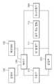
- FIG. 3is a block diagram showing the main control system of the RF treatment device of FIG. 1.
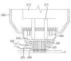
- FIG. 4is a cross-sectional view schematically showing the internal structure of the distal end of the handpiece of FIG. 2.
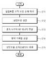
- FIG. 5is a flowchart illustrating a treatment method using an RF treatment device according to an embodiment of the present invention.
- 6 to 7are views for explaining a treatment method using an RF treatment device according to an embodiment of the present invention.
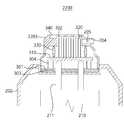
- FIG. 8is a cross-sectional view schematically showing the internal structure of a distal end portion of a handpiece according to another embodiment of the present invention.
- FIG. 9is a flowchart illustrating a treatment method using the handpiece of FIG. 8.
- FIGS. 10 and 11are cross-sectional views schematically showing the internal structure of a distal end portion of a handpiece according to another embodiment of the present invention.
- the term 'RF treatment device'includes all devices for treating animals such as mammals, including humans.
- the treatment devicemay include various devices that deliver and treat RF energy for the purpose of improving the condition of a lesion or tissue.
- the apparatus for treating skin lesionswill be mainly described, but the present invention is not limited thereto, and various apparatuses used to deliver RF energy to various affected areas, including apparatuses for surgically treating organ lesions in the body. It can be applied to.
- tissuerefers to a set of cells constituting various body organs of animals, including humans, and includes various tissues constituting various organs in the body, including skin tissue.
- the term 'insertion portion'means a configuration that is inserted into the tissue of the treatment device.
- the needle, micro-needle, and catheterinclude various configurations that are configured with a pointed, elongated structure to penetrate the surface of the tissue and be inserted into the tissue.
- FIG. 1is a perspective view showing an RF treatment device according to a first embodiment of the present invention
- FIG. 2is an exploded perspective view showing a handpiece of the RF treatment device of FIG. 1.
- the medical RF deviceis composed of an RF treatment device, and the RF treatment device 1 is a main body 100 and a handpiece 200 in which a user grasps and performs treatment It is configured to include.
- An RF generator 111may be provided inside the main body 100.
- the RF generator 111generates RF energy used for treatment.
- the RF generator 111is configured to generate and transmit RF energy in the form of pulses rather than continuous waveforms.
- the RF generator 111may generate RF pulses of various parameters (eg, output, pulse duration, pulse interval, frequency, etc.) according to the patient's constitution, treatment purpose, and treatment site.
- the RF pulse generated in the RF generator of the present embodimentis a therapeutic RF pulse used for the purpose of treating tissue.
- the RF energy used for skin treatmentcan be adjusted in the range of 0.1 to 0.8 MHz.
- a refrigerant tank(not shown) may be provided inside the main body 100.
- the refrigerant tankstores the cooling gas that is supplied to the surface of the tissue in which heat is generated due to RF energy being supplied during the treatment process in a pressurized gas or liquid state.
- cryogen and / or airmay be used, and various gases that are harmless to the skin and can degrade heat of the skin may be used.
- the outer surface of the main body 100may include a switch 101 for controlling the operation of the treatment device, including on / off of the power supply, and a display unit 102 for displaying various information including the operation contents of the treatment device.
- the display unit 102may be configured as a touch screen to display various types of information, and at the same time, the user can set the treatment contents directly through the display unit 102.
- the handpiece 200is connected to the main body by the connecting portion 300.
- the connection unit 300may transmit power, control signals, and the like necessary for various devices of the handpiece 200 to operate from the main body 100.
- the connection unit 300may be formed of a cable including various signal lines, power lines, or the like, or may be formed of a bending structure that can be easily bent by user manipulation.
- connection part 300is a cooling gas provided from the first line 300a for transmitting RF energy generated by the RF generator 111 of the body 100 to the handpiece 200 and the refrigerant tank of the body 100 It may include a second line (300b) for transferring to the handpiece (200).
- the housing 201 of the handpiece 200may be configured to be detachable by a handpiece body 202 and a tip 203.
- a handpiece manipulation unit 230 and a handpiece display unit 220may be provided on the outer surface of the handpiece body 202.
- the handpiece manipulation unit 230is configured to manipulate on / off of the handpiece 200, adjust the insertion depth of the insertion unit 250, or adjust the amount of energy transmitted through the insertion unit 250, etc. do.
- the display unit 220 of the handpiecemay display various information required during the setting mode or treatment to the user. Therefore, the user can easily grasp the treatment contents through the display unit 220 while performing treatment by operating the manipulation unit 230 while holding the handpiece 200 in the hand.
- the driving unit 210is installed inside the handpiece 200.
- the driving unit 210is configured to selectively insert into the tissue by moving the insertion unit 250.
- the driving unit 210may be configured using various linear actuators such as solenoids and hydraulic / pneumatic cylinders, and linear motors.
- the driving unit of this embodimentis configured to linearly move the output terminal 211 provided at one end in the longitudinal direction.
- a plurality of needles 320(see FIG. 4) corresponding to the insertion unit 250 are disposed, and as the output terminal moves linearly, the insertion unit 250 has one end (handling) of the handpiece 200. It is configured to appear at one end).
- the insertion unit 250may be inserted into or drawn out of the tissue of the patient while the insertion unit 250 is advanced / retracted by the driving of the driving unit 210.
- the insertion part 250is provided in the handpiece 200 in a configuration that penetrates through the tissue surface and is inserted into the tissue.
- the insertion portion 250 of the present embodimentis composed of a microneedle (320, see FIG. 4), which is easy to insert tissue, but may also be configured in various structures such as a singular needle structure, a catheter, and the like.
- the micro-needles 320 of this embodimentmay be needles having a diameter in the range of several to several thousand ⁇ m, and preferably needles having a diameter in the range of 10 to 1000 ⁇ m.
- the insertion unit 250is a component that is inserted into the tissue of the patient's body, and repeated use may cause hygiene problems. Therefore, the insertion portion 250 of the present embodiment is provided on the detachable tip 203 at the end of the handpiece body 202, and the tip 203 is configured to be used after treatment.
- a detachable protrusion 307 protruding outwardis formed on an outer wall of the base 301 (see FIG. 4) forming the bottom surface of the tip 203.
- a guide groove 241 guiding the entry of the detachable protrusion 307 and a detachable protrusion 307 entered along the guide groove 241are prevented from being detached from the recess 240 to which the tip 203 is coupled.
- Deviation prevention groove 242 for formingis formed.
- the detachable protrusion 307 of the tip 203is guided along the guide groove 241 and is installed on the handpiece in such a way that it is fastened to the escape prevention groove 242.
- the tip 203is detachably installed on the handpiece body 202, and the piece body 202
- the coupling structure of the and the tip 203may be variously modified. It is also possible that the tip 203 is integrally formed with the handpiece body 202.
- Tip 203is composed of a plurality of micro-needles (320, see FIG. 4), the insertion unit 250 is built-in, and is detachable to the recess 240 provided at one end of the handpiece 200 body. Is installed. A plurality of holes (not shown) in which the above-described output terminal 211 can be selectively inserted is provided on the rear surface of the tip 203. Accordingly, the plurality of micro-needles 320 accommodated in the tip 203 according to the above-described output terminal 211 is configured to be able to advance / retract.
- the micro needle 230 of the tip 203is electrically connected to the RF circuit in the handpiece 200, and is treated through the micro needle 320 RF energy can be transferred into the tissue of the site.
- FIG. 3is a block diagram showing the main control system of the RF treatment device of FIG. 1.
- a control structure of the RF treatment apparatus according to the present embodimentwill be described in more detail with reference to FIG. 3.
- the control unit 140is a component that controls the operation of various components of the main body 100 and the handpiece 200. As shown in FIG. 3, the control unit 140 controls the operation of the driving unit 210 of the handpiece, so that the insertion unit 250 is inserted into the tissue, withdrawn from the tissue, or of the insertion unit 250. Insertion depth can be adjusted.
- control unit 140may control the RF generator 111 to adjust the on / off operation of the RF pulse and the parameters of the RF pulse.
- the RF treatment device 1can insert a microneedle into the tissue and provide an RF pulse having appropriate parameters.
- control unit 140may control the cooling gas valve 112 to adjust the supply timing of the cooling gas, the supply amount of the cooling gas, and the like.
- the cooling gas valve 112may be provided between the refrigerant tank and the second line 300b, or may be provided in the hand piece 200.
- the setting unit 120is a configuration in which a user can set treatment contents.
- the control unit 140controls various configurations to perform a treatment operation based on the content set by the user through the setting unit 120.
- the setting unit 120may be composed of the above-described display unit 102 and / or switch, and various options are displayed to the user through the display unit 102, and the user can set the selected option in a manner. .
- the RF treatment device 1further includes a memory unit 130 in which various data are stored.
- the control unit 140may store information necessary for controlling the RF treatment device in a memory unit, or may load data stored in the memory unit 130 and use it for control.
- the RF treatment devicefurther includes a monitoring unit 260.
- the monitoring unit 260is configured to monitor the state information of the tissue corresponding to the treatment location during treatment.
- the monitoring unit 260monitors the temperature of the tissue, the impedance of the RF energy transmission path formed through the tissue, or monitors at least one of various information necessary for treatment, such as whether the handpiece is in contact or pressurized. It is a composition.
- the monitoring unit 260 of the present embodimentis provided on a path through which RF energy is transmitted, and may be configured to monitor the impedance of the path through which the RF energy is transmitted.
- the monitoring unitmay be provided on the RF transmission path in the handpiece, or may be provided on the RF transmission path in the body.
- the monitoring unit 260may monitor the impedance value by passing a separate test current to the insertion unit 250, or may monitor the impedance value measured while the therapeutic RF pulse is transmitted. At this time, since the measured impedance changes depending on the characteristics of the patient and the change in tissue state, it can be interpreted as 'tissue impedance' for convenience.
- the impedance of the tissueis monitored by the monitoring unit 260, and treatment contents can be adjusted based on this.
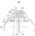
- FIG. 4is a cross-sectional view schematically showing the internal structure of the distal end of the handpiece of FIG. 2.
- the inside of the tip 230is provided with an RF transmission unit 310 in which a plurality of needles 320 are installed.
- the plurality of needles 320are fixedly installed in the RF transmission unit 310 in a matrix form.
- the RF transmission unit 310is formed with an electrical circuit that is connected to a plurality of needles 320, respectively.
- the electrical circuit formed on the RF transmission unit 310is electrically connected to the output terminal 211 so that RF energy transmitted through the output terminal 211 is transmitted to the plurality of needles 320 through the RF transmission unit 310. .
- the tip of the tip 230may form a portion adjacent to or in contact with the patient's skin during treatment, and a plurality of through holes 302 in which a plurality of needles 320 appear at the tip of the tip 230 are formed. .
- At least one hole 303 through which the output terminal 211 may passis provided below the tip 230.
- the output terminal 211presses the RF transmission unit 310 while linearly moving along the hole 303 when the driving unit 210 is operated.
- the rear surface of the RF transmission unit 310is seated on the support 304 inside the tip 230, and the front surface of the RF transmission unit 310 is pressed by an elastic member 330 installed inside the tip 230.
- the RF transmission unit 310moves away from the support 304 and a plurality of needles 320 protrude toward the front of the through hole 302. It is inserted into the skin tissue.
- the output terminal 211is retracted by the driving of the driving unit 210
- the RF transmission unit 310is retracted by the restoring force of the elastic member 330, and the plurality of needles 320 are also inward of the tip 230.
- the circuit of the RF transmission unit 310may be configured to be electrically connected to the RF generator 111 of the body 100 when the tip 230 is installed on the handpiece body 202. have.
- the circuit of the RF transmission unit 310may be configured to be selectively electrically connected to the RF generation unit 111 when pressed by the output terminal 211 (eg, an electrode at the end of the output terminal 211) This is formed, it is electrically connected to the RF transmission unit 310 when pressurized).
- Each needle 320may be composed of micro-needles having a diameter of approximately 5 to 500 ⁇ m.
- the needle 320is made of a conductive material to transmit RF energy.
- the portion of the surface of each needle except the tipis formed of an insulating material, and is configured to not transmit RF energy to the tissue.
- a part of the tip of each needleserves as an electrode, and is configured to transmit RF energy to the tissue only through the tip. Therefore, it is possible to selectively transmit RF energy to the portion where the end of the needle is located during treatment.
- a cooling channel 205 passing through a side wall of the tip 230is formed at one side of the tip 203.
- the cooling channel 205is connected to the second line 300b to allow cooling gas supplied from the refrigerant tank to flow into the tip 203.
- Cooling gas introduced into the inside of the tip 203 through the cooling channel 205is discharged through the through-hole 302 to cool the skin tissue whose temperature is increased by RF energy delivered through the plurality of needles 320 Order. Even when the plurality of needles 320 pass through the through-hole 302, the through-hole 302 may allow the cooling gas flowing into the tip 203 to be discharged between the through-hole 302 and the needle 320.
- Silver needle 320is preferably formed larger than the diameter.
- a second line coupling port 204may be formed on one side of the tip 203 to extend the cooling channel 205 to the outside of the tip 203.
- the coupling port 204illustrates an example of a configuration that facilitates the connection of the second line 300b and the tip 203, and may be variously modified according to embodiments.
- the coupling portmay be configured to be recessed on the sidewall of the tip 203 so that the end of the second line 300b is fitted.
- FIGS. 6 to 7are views for explaining a treatment method using an RF treatment device according to an embodiment of the present invention to be.
- the operation of the RF treatment apparatus according to the present embodimentwill be described with reference to FIGS. 4 to 7.
- the insertion unit 250 of the treatment deviceis placed on the surface of the tissue to be treated (S11). Specifically, the distal end (tip 203) of the handpiece 200 with the insertion portion 250 is positioned to be in contact with or adjacent to the surface of the tissue corresponding to the treatment location.
- the control unit 140operates the driving unit 210 so that the insertion unit 250 moves forward. That is, the control unit 140 operates the driving unit 210, as shown in FIG. 6, after the tip ends of the plurality of needles 320 pass through the through hole 302, then penetrate the surface of the tissue T To be inserted into the tissue T.
- the control unit 140controls the RF generation unit 111 so that RF energy is generated through the first line 300a, the output terminal 211, the RF transmission unit 310, and the plurality of needles 320. To be delivered inside.
- a step of supplying a cooling gasis performed (S14).
- the control unit 140controls the cooling gas valve 112, so that the cooling gas from the refrigerant tank is the second line 300b, the housing of the handpiece 200 through the cooling channel 205, as shown in FIG. (201) to be introduced into the interior.
- the cooling gas introduced into the housing 201is sprayed to the surface of the tissue T through the through hole 302.
- the temperature T of the tissue T absorbing RF energyincreases, and the cooling gas injected through the through-hole 302 may cool the tissue T to lower the temperature rise.
- a step of extracting the insertion unit 250 from the tissueis performed (S15).
- the control unit 140operates the driving unit 210 to allow the insertion unit 250 to retreat. That is, the control unit 140 may operate the driving unit 210 to complete the treatment by allowing the tip ends of the plurality of needles 320 to escape from the tissue surface.
- each stepis shown as being sequentially performed, but is not limited thereto. It is also possible to proceed by changing the order of each step, and it is also possible that a plurality of steps are performed simultaneously.
- the step (S14) of supplying the cooling gasmay be performed simultaneously with at least one of the step of inserting the insert (S12) and the step of transmitting RF energy into the tissue (S13), and extracting the insert from the tissue. It may also proceed while (S15) is in progress.
- the RF treatment apparatus 1 and the treatment method according to the present embodimentprovide cooling gas to a treatment site to which RF energy is supplied to cool a tissue having a temperature rising during treatment to prevent burns and to be more effective. It makes treatment possible.
- the treatment method of the RF treatment apparatus 1allows cooling gas to be sprayed through the through-hole 302 of the handpiece 200 positioned closest to the treatment site, thereby effectively cooling the treatment site. You can.
- FIG. 8is a cross-sectional view schematically showing the internal structure of a distal end portion of a handpiece according to another embodiment of the present invention.
- the handpiece 2200according to another embodiment of the present invention further includes a temperature measuring unit 340 as compared to the handpiece 200 according to the above-described embodiment.
- the temperature measuring unit 340measures the temperature of the tissue positioned so that the tip 2203 is positioned adjacent to or in contact with.
- the temperature measurement unit 340may include a contact (electronic) temperature measurement sensor or a non-contact (optical) temperature measurement sensor.
- the temperature measuring unit 340includes a contact-type temperature measuring sensor, treatment is performed on the tissue while the tip 2203 is in contact with the tissue surface, and the temperature measuring unit 340 is a non-contact temperature measuring sensor.
- the tip 2203may be treated with the tissue in a state adjacent to the surface of the tissue.
- FIG. 8shows an example in which the temperature measuring unit 340 is provided at the tip of the tip 2203, but if the temperature of the tissue in which treatment is being performed can be measured, the temperature measuring unit 340 is another portion of the tip 2203. Or it may be provided on the handpiece body 202.
- the temperature measurement unit 340is connected to the control unit 140 and transmits a temperature measurement result to the control unit 140.
- the control unit 140may control the supply state of the cooling gas by controlling the cooling gas valve 112 based on the temperature measurement result of the temperature measurement unit 340.
- FIG. 9is a flowchart illustrating a treatment method using the handpiece of FIG. 8.
- the treatment method using the RF treatment apparatusalso includes placing the insertion portion on the surface of the tissue to be treated (S21), inserting the insertion portion into the tissue (S22), and And transmitting RF energy into the tissue (S23).
- Thisis the same or similar to the steps S11, S12 and S13 described in the treatment method using the RF treatment device 1 of the above-described embodiment, so a detailed description thereof will be omitted.
- a step of measuring the temperature of the tissue surfaceis performed (S24).
- the temperature measuring unit 340measures the temperature of the tissue surface and transmits it to the control unit 140.
- the temperature measuring unit 340may repeatedly perform a process of measuring the temperature of the tissue surface and transmitting it to the control unit 140 during treatment.
- the control unit 140compares the temperature of the tissue surface received from the temperature measurement unit 340 with a reference temperature.
- the reference temperaturemay be a temperature value previously input or a temperature value automatically calculated by the controller 140.
- FIG. 9illustrates an example of determining whether the measured temperature exceeds the reference temperature, but is not limited thereto, and is set to determine whether the measured temperature is greater than or equal to the reference temperature, or whether the measured temperature is less than or equal to the reference temperature It may be set to determine whether or not.
- the reference temperaturemay be set to compare the measured temperature with an upper limit temperature and a lower limit temperature, including a cooling start temperature and a cooling stop temperature.
- control unit 140determines whether the measured temperature exceeds the reference temperature.
- a step of supplying cooling gasis performed (S26).
- the control unit 140controls the cooling gas valve 112 to supply cooling gas through the cooling channel 205 into the handpiece 2200 and treat it through the through hole 302 Is sprayed onto the surface of the tissue in progress.
- the controller 140may compare the cooling start temperature among the reference temperatures with the measured temperature.
- step S27When the measured temperature does not exceed the reference temperature, a step of stopping supply of cooling gas is performed (S27). And step S25 is performed again.
- the step S27includes not only stopping the supply of the cooling gas that has been provided to the surface of the tissue, but also maintaining the state in which the supply of the cooling gas is not made. If the measured temperature does not exceed the reference temperature, the control unit 140 controls the cooling gas valve 112 so that cooling gas is not supplied through the second line 300b. If the reference temperature includes the cooling start temperature and the cooling stop temperature, in step S27, the controller 140 may compare the cooling stop temperature among the reference temperatures with the measured temperature.
- Step S28is the same or similar to step S15 described above, and thus a detailed description thereof will be omitted.
- each stepis illustrated as being sequentially performed, but is not limited thereto. It is also possible to proceed by changing the order of each step, and it is also possible that a plurality of steps are performed simultaneously.
- the RF treatment apparatus and treatment method using the handpiece 2200measures the temperature of the tissue surface and controls the supply of cooling gas in response to the temperature of the tissue surface, thereby enabling more effective treatment. In particular, it is possible to prevent frostbite from occurring in the tissue due to excessive supply of cooling gas.
- FIG. 10is a cross-sectional view schematically showing the internal structure of a distal end portion of a handpiece according to another embodiment.
- the position of the cooling channel 3205is different from the handpiece 3200 according to the present embodiment, compared to the handpiece 200 according to the above-described embodiment.
- the cooling channel 205is formed through the tips 203 and 2203, while the handpiece 3200 according to the present embodiment has the cooling channel 3205. It is formed on the handpiece body 202 side.
- the cooling channel 3205is formed by a cooling tube 3204 exposed through the driving unit 210 to the tip of the handpiece body 202.
- the cooling pipe 3204may be fixedly installed in the handpiece body 202 regardless of whether the driving unit 210 moves the output shaft 211, but is not limited thereto, and according to an embodiment, the driving unit 210 may include an output shaft ( When moving 211), the output shaft 211 may be configured to be integrally moved.
- the second line 300b that delivers the cooling gas to the cooling channel 3205may be connected to the cooling channel 3205 through the rear end of the handpiece body 202 together with the first line 300a.
- the cooling pipe 3204may be exposed to the rear end of the handpiece body 202 and connected to the second line 300b, but according to an embodiment, the cooling pipe 3204 and the second line 300b may be handpiece bodies.
- 202may be connected inside, or the cooling pipe 3204 and the second line 300b may be integrally formed.
- the cooling pipe entry holeis provided in the base 301 and the RF transmission part 310 of the tip 3203. Unsigned) may be formed.
- the cooling tube 3204 exposed at the tip of the handpiece body 202easily enters the cooling tube entrance hole, so that the handpiece of the cooling tube 3204
- the portion exposed at the tip of the body 202may be formed of a rigid material.
- the tip of the cooling tube 3204 in the state where the tip 3203 is coupled to the handpiece body 202will be located between the RF transmission part 310 and the tip of the tip 3203. You can.
- the end of the cooling tube 3204may be located in the RF transmission unit 310 according to an embodiment.
- the handpiece 3200is also formed with a cooling channel 3205 through the cooling tube 3204 to the inside of the tip 3202, so that the cooling gas passes through the through hole 302 of the handpiece 2200. Since it is sprayed, it is possible to effectively cool the treatment site.
- the end of the cooling tube 3204may be located between the base 301 and the RF transmission unit 310.
- the cooling gas supplied between the base 301 and the RF transmission unit 310has a through hole in a state in which the driving unit 210 advances the output terminal 211 so that the RF transmission unit 310 is separated from the support 304. It may be discharged to the outside of the tip 3202 through 302.
- the support 304may be formed in a ring shape surrounding the periphery of the cooling tube 3204, and when the RF transmission unit 310 is in contact with the support 304, cooling gas is supplied to the RF transmission unit 310 and the support ( 304). That is, the space divided by the RF transmission unit 310 and the support 304 may be a closed space.
- the upper portion of the supporter 304 or the lower surface of the RF transmission unit 310is provided with a sealing member at a portion of the supporter 304 in contact with the upper end of the RF transmission unit 310 and the supporter 304.
- the spacecan be formed as a closed space.
- the cooling gas introduced into the tip 3203 through the cooling channel 3205is discharged through the through-hole 302 only when the plurality of needles 320 are moved to be inserted into the tissue. You can. Therefore, the cooling gas is discharged through the through-hole 302 in a state in which the RF transmission unit 310 and the plurality of needles 320 are moved toward the through-hole 302 for treatment, and RF delivery that does not proceed with treatment In the state where the part 310 is in contact with the upper end of the support 304, it may be prevented from being discharged through the through-hole 302.
- the handpiece 3200may also further include a temperature measuring unit 340 (see FIG. 8). Since the control of the cooling gas using the temperature measuring unit 340 has already been described, a detailed description thereof will be omitted.
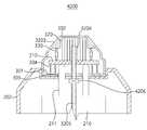
- FIG. 11is a cross-sectional view schematically showing the internal structure of a distal end portion of a handpiece according to another embodiment.
- the handpiece 4200 according to the present embodimentfurther includes a valve 4206 on the cooling channel 3205 as compared to the handpiece 3200 according to the above-described embodiment. .
- the valve 4206is a valve that opens and closes the cooling channel 3205, and the valve 4206 may be configured to open and close the cooling channel 3205 in connection with the movement of the plurality of needles 320 and the RF transmission unit 310. have.
- the valve 4206may be configured to open and close the cooling channel 3205 in connection with the movement of the output shaft 211.
- the valve 4206opens the cooling channel 3205 so that the cooling gas is organized through the through hole 302.
- the valve 4206closes the cooling channel 3205 to block the cooling gas from being supplied into the tip 3203. .
- the valve 4206may be configured to be opened and closed in a mechanical manner synchronously driven with movement of the output shaft 211, or may be configured to be opened and closed in an electrical manner by a control signal of the driving unit 210.
- valve 4206may be provided in the tip 3203.
- the valve 4206may be configured to open and close the cooling channel 3205 in connection with the movement of the output shaft 211 or the RF transmission unit 310.
- the handpiece 4200blocks the cooling gas from being injected into the tip 3203 when the treatment is not in progress, and the cooling gas is an RF transmission unit 310 and a plurality of needles for treatment ( After moving 320), the cooling gas may be supplied into the tip 3203.
- a treatment devicethat transmits RF energy to skin tissue and proceeds with treatment.
- thisis an example and can be applied to a treatment device targeting tissue other than skin tissue.
- itcan be applied to various treatment devices that transmit energy such as RF, laser, and ultrasound, as well as treatment devices that treat by RF energy delivery methods, and can be applied to therapeutic substances (eg, drugs, anesthetics, stem cells, etc.) It can be applied to a variety of treatment devices, such as treatment devices to treat in a manner that delivers.
- the treatment apparatus composed of the main body and the handpiecehas been mainly described, it is not limited thereto, and it is revealed that it can be applied to a treatment apparatus composed of a single module type of the handpiece.
- a therapeutic handpieceincludes a housing having at least one through hole formed at a tip, an insertion part penetrating the tissue surface and being inserted into the tissue while at least a part is exposed through the through hole, and the And a cooling channel providing cooling gas supplied to the tissue surface through a through hole.
- the cooling channelmay be formed through one side of the housing to provide the cooling gas into the housing.
- An RF transmission unit transmitting RF energy to the insertion unit, and the cooling channelmay be formed through the RF transmission unit.
- the driving unitmay further include a driving unit that moves the insertion unit such that at least a portion of the insertion unit passes through the through hole.
- the cooling channelmay be formed to supply the cooling gas through the driving unit and toward the through hole.
- the cooling gasmay be supplied through the cooling channel after the driving unit moves the insertion unit.
- the cooling channelmay be opened and closed in connection with an operation of the driving unit moving the insertion unit.
- a temperature measuring unit for measuring the temperature of the tissue surfacemay be further included.
- the cooling gasmay be supplied based on the temperature of the tissue surface measured by the temperature measuring unit.
- the cooling gasmay include at least one of cryogen and air.
- the method of controlling a treatment apparatusincludes the steps of positioning an insertion portion on a tissue surface, allowing at least a portion of the insertion portion to penetrate the tissue surface and insert into the tissue, and cooling gas to the tissue surface It includes the step of supplying.
- the step of supplying the cooling gasmay proceed after the step of transmitting the RF energy.
- the step of supplying the cooling gasmay proceed when the temperature of the tissue surface is above or above a preset cooling start temperature.
- the step of stopping the supply of the cooling gasmay be performed when the temperature of the surface of the tissue is below or below a predetermined cooling stop temperature.
- the insertion portionmoves toward the tissue, and the step of supplying the cooling gas may proceed after the cooling gas moves after the insertion portion moves toward the tissue surface.
- the RF treatment apparatusincludes a body including an RF generator and a refrigerant tank, and a handpiece connected to the body, wherein the handpiece includes a housing in which at least one through hole is formed at a tip, Cooling gas delivered from the refrigerant tank and the insertion portion that penetrates the tissue surface and is inserted into the tissue and the RF energy transmitted from the RF generator is applied inside the tissue while at least a part is exposed through the through hole is exposed. And a cooling channel provided to the tissue surface through the through hole.
- first linetransmits the RF energy from the RF generator to the handpiece
- second linefrom the refrigerant tank Cooling gas may be delivered to the cooling channel.
- the handpieceis further connected to the first line and further includes an RF transmission unit transmitting RF energy to the insertion unit, and the cooling channel may be formed through the RF transmission unit.
- the first line and the second linemay be respectively connected to the RF transmission unit and the cooling channel through the rear end of the housing.
- the first linetransmits the RF energy to the insert through the rear end of the housing, and the second line can be connected to the cooling channel through one side of the housing.
Landscapes
- Health & Medical Sciences (AREA)
- Life Sciences & Earth Sciences (AREA)
- Surgery (AREA)
- Engineering & Computer Science (AREA)
- Animal Behavior & Ethology (AREA)
- Veterinary Medicine (AREA)
- Public Health (AREA)
- General Health & Medical Sciences (AREA)
- Biomedical Technology (AREA)
- Heart & Thoracic Surgery (AREA)
- Medical Informatics (AREA)
- Molecular Biology (AREA)
- Nuclear Medicine, Radiotherapy & Molecular Imaging (AREA)
- Physics & Mathematics (AREA)
- Otolaryngology (AREA)
- Plasma & Fusion (AREA)
- Oral & Maxillofacial Surgery (AREA)
- Pathology (AREA)
- Vascular Medicine (AREA)
- Surgical Instruments (AREA)
Abstract
Description
Translated fromKorean본 발명은 치료용 핸드 피스, 이를 포함하는 치료 장치 및 이를 이용한 치료 방법에 관한 것으로서, 보다 상세하게는 인체의 조직 내부에 삽입되어 침습 방식으로 치료를 진행하는 치료용 핸드 피스, 이를 포함하는 치료 장치 및 이를 이용한 치료 방법에 관한 것이다.The present invention relates to a handpiece for treatment, a treatment device including the same, and a treatment method using the same, more specifically, a treatment handpiece inserted into the tissue of the human body to perform treatment in an invasive manner, and a treatment device comprising the same And a treatment method using the same.
조직을 치료하는 방식은 조직의 외부에서 조직을 치료하는 방식과, 치료장치의 일부 또는 전부를 조직 내부로 삽입하여 진행하는 침습 치료 방식으로 구분될 수 있다. 이 중 침습 치료 방식은 주로 니들 또는 카테터 등과 세경의 삽입부를 갖는 치료 장치를 이용하며, 치료 장치를 조직 내부의 타겟 위치까지 삽입한 후 치료를 진행한다.The method of treating tissue may be divided into a method of treating tissue from outside the tissue, and an invasive treatment method in which some or all of the treatment devices are inserted into the tissue to proceed. Among these, the invasive treatment method mainly uses a treatment device having a needle or catheter, etc., and a small-diameter insert, and after the treatment device is inserted into a target position inside the tissue, treatment is performed.
이러한 침습 치료 방식은 조직 내부에 치료 물질을 전달하거나, 조직 내부의 특정 조직과 인접한 상태에서 기계적으로 동작하여 수술적 치료를 진행하거나, 조직 내부의 타겟 위치에 에너지를 전달하는 등 다양한 치료 행위를 포함한다. 이러한 치료 방식은 공개특허공보 10-2011-0000790호 등에 개시되어 있으며, 이 이외에도 다양한 방식으로 적용되고 있다.Such invasive treatment methods include various treatment actions, such as delivering a therapeutic substance inside a tissue, mechanically operating in a state adjacent to a specific tissue inside a tissue, performing surgical treatment, or transmitting energy to a target location inside the tissue. do. Such a treatment method is disclosed in Patent Publication No. 10-2011-0000790, etc., and is applied in various other ways.
침습 치료 방식 중, RF 전극의 일부 또는 전부를 조직 내부에 삽입하여 RF 에너지를 전달하는 RF 치료 방식은 전극을 통해 조직으로 RF 전류를 흐르게 하면, 조직이 저항으로 역할하면서 열 에너지가 발생하는 원리를 이용한다.Among the invasive treatment methods, the RF treatment method in which a part or all of the RF electrode is inserted into the tissue to deliver RF energy flows through the electrode to flow RF current to the tissue. To use.
그러나, 조직의 온도가 과도하게 상승하는 경우에는 치료 중에 화상이 발생할 우려가 있다.However, if the temperature of the tissue is excessively increased, there is a risk of burns during treatment.
본 발명이 해결하고자 하는 과제는, 치료 중인 조직의 과도한 온도 상승을 방지할 수 있는 치료 장치 등을 제공하는 것이다.The problem to be solved by the present invention is to provide a treatment device or the like capable of preventing excessive temperature rise of the tissue being treated.
본 발명의 과제들은 이상에서 언급한 과제로 제한되지 않으며, 언급되지 않은 또 다른 과제들은 아래의 기재로부터 당업자에게 명확하게 이해될 수 있을 것이다.The problems of the present invention are not limited to the problems mentioned above, and other problems not mentioned will be clearly understood by those skilled in the art from the following description.
상기 과제를 해결하기 위한 본 발명의 실시예에 따른 치료용 핸드피스는, 선단에 적어도 하나의 관통홀이 형성된 하우징, 상기 관통홀을 통해 적어도 일부가 노출된 상태에서 조직 표면을 관통하여 조직 내부로 삽입되는 삽입부 및 상기 관통홀을 통해 상기 조직 표면으로 공급되는 냉각 가스를 제공하는 냉각 채널을 포함한다.The treatment handpiece according to an embodiment of the present invention for solving the above problems is a housing in which at least one through hole is formed at a distal end, and penetrates the tissue surface in a state where at least a part is exposed through the through hole to penetrate into the tissue. It includes an insertion portion to be inserted and a cooling channel that provides cooling gas supplied to the tissue surface through the through hole.
상기 과제를 해결하기 위한 본 발명의 실시예에 따른 치료장치의 제어방법은, 조직 표면 상에 삽입부를 위치시키는 단계, 상기 삽입부의 적어도 일부가 상기 조직 표면을 관통하여 조직 내부로 삽입되도록 하는 단계 및 상기 조직 표면으로 냉각 기체를 공급하는 단계를 포함한다.The control method of the treatment apparatus according to the embodiment of the present invention for solving the above problems includes: placing an insertion portion on a tissue surface, allowing at least a portion of the insertion portion to penetrate the tissue surface and be inserted into the tissue; And supplying a cooling gas to the tissue surface.
상기 과제를 해결하기 위한 본 발명의 실시예에 따른 RF 치료 장치는, RF 발생부와 냉매 탱크를 포함하는 본체 및 상기 본체와 연결되는 핸드피스를 포함하며, 상기 핸드피스는, 선단에 적어도 하나의 관통홀이 형성된 하우징, 상기 관통홀을 통해 적어도 일부가 노출된 상태에서 조직 표면을 관통하여 조직 내부로 삽입되고 상기 RF 발생부로부터 전달된 RF 에너지를 상기 조직 내부에 인가하는 삽입부 및 상기 냉매 탱크로부터 전달되는 냉각 가스를 상기 관통홀을 통해 상기 조직 표면으로 제공하는 냉각 채널을 포함한다.RF treatment apparatus according to an embodiment of the present invention for solving the above problems, includes a body including an RF generator and a refrigerant tank and a handpiece connected to the body, the handpiece, at least one at the tip A housing formed with a through hole, an insertion part that penetrates the tissue surface and is inserted into the tissue while at least a part is exposed through the through hole, and inserts RF energy transmitted from the RF generator into the tissue and the refrigerant tank And a cooling channel providing cooling gas delivered from the through-hole to the tissue surface.
본 발명의 기타 구체적인 사항들은 상세한 설명 및 도면들에 포함되어 있다.Other specific matters of the present invention are included in the detailed description and drawings.
본 발명의 실시예들에 의하면 적어도 다음과 같은 효과가 있다.According to embodiments of the present invention has at least the following effects.
치료 중인 조직의 과도한 온도 상승을 방지할 수 있다.It can prevent excessive temperature rise of the tissue being treated.
본 발명에 따른 효과는 이상에서 예시된 내용에 의해 제한되지 않으며, 더욱 다양한 효과들이 본 명세서 내에 포함되어 있다.The effects according to the present invention are not limited by the contents exemplified above, and more various effects are included in the present specification.
도 1은 본 발명의 제1 실시예에 따른 RF 치료 장치를 도시한 사시도이다.1 is a perspective view showing an RF treatment device according to a first embodiment of the present invention.
도 2는 도 1의 RF 치료 장치의 핸드피스를 도시한 분해 사시도이다.FIG. 2 is an exploded perspective view showing the handpiece of the RF treatment device of FIG. 1.
도 3은 도 1의 RF 치료 장치의 주요 제어 계통을 도시한 블록도이다.FIG. 3 is a block diagram showing the main control system of the RF treatment device of FIG. 1.
도 4는 도 2의 핸드피스의 선단부의 내부 구조를 개략적으로 도시한 단면도이다.4 is a cross-sectional view schematically showing the internal structure of the distal end of the handpiece of FIG. 2.
도 5는 본 발명의 일 실시예에 따른 RF 치료 장치를 이용한 치료 방법을 도시한 순서도이다.5 is a flowchart illustrating a treatment method using an RF treatment device according to an embodiment of the present invention.
도 6 내지 도 7은 본 발명의 일 실시예에 따른 RF 치료 장치를 이용한 치료 방법을 설명하기 위한 도면이다.6 to 7 are views for explaining a treatment method using an RF treatment device according to an embodiment of the present invention.
도 8은 본 발명의 다른 실시예에 따른 핸드피스의 선단부의 내부 구조를 개략적으로 도시한 단면도이다.8 is a cross-sectional view schematically showing the internal structure of a distal end portion of a handpiece according to another embodiment of the present invention.
도 9는 도 8의 핸드피스를 이용한 치료 방법을 도시한 순서도이다.9 is a flowchart illustrating a treatment method using the handpiece of FIG. 8.
도 10 및 도 11은 본 발명의 다른 실시예에 따른 핸드피스의 선단부의 내부 구조를 개략적으로 도시한 단면도이다.10 and 11 are cross-sectional views schematically showing the internal structure of a distal end portion of a handpiece according to another embodiment of the present invention.
본 발명의 이점 및 특징, 그리고 그것들을 달성하는 방법은 첨부되는 도면과 함께 상세하게 후술되어 있는 실시예들을 참조하면 명확해질 것이다. 그러나 본 발명은 이하에서 개시되는 실시예들에 한정되는 것이 아니라 서로 다른 다양한 형태로 구현될 수 있으며, 단지 본 실시예들은 본 발명의 개시가 완전하도록 하고, 본 발명이 속하는 기술분야에서 통상의 지식을 가진 자에게 발명의 범주를 완전하게 알려주기 위해 제공되는 것이며, 본 발명은 청구항의 범주에 의해 정의될 뿐이다. 명세서 전체에 걸쳐 동일 참조 부호는 동일 구성 요소를 지칭한다.Advantages and features of the present invention, and methods for achieving them will be clarified with reference to embodiments described below in detail together with the accompanying drawings. However, the present invention is not limited to the embodiments disclosed below, but may be embodied in various different forms, and the present embodiments merely make the disclosure of the present invention complete, and those of ordinary skill in the art to which the present invention belongs. It is provided to fully inform the person having the scope of the invention, which is defined only by the scope of the claims. The same reference numerals refer to the same components throughout the specification.
또한, 본 명세서에서 기술하는 실시예들은 본 발명의 이상적인 예시도인 단면도 및/또는 개략도들을 참고하여 설명될 것이다. 따라서, 제조 기술 및/또는 허용 오차 등에 의해 예시도의 형태가 변형될 수 있다. 또한 본 발명에 도시된 각 도면에 있어서 각 구성 요소들은 설명의 편의를 고려하여 다소 확대 또는 축소되어 도시된 것일 수 있다. 명세서 전체에 걸쳐 동일 참조 부호는 동일 구성 요소를 지칭한다.In addition, the embodiments described herein will be described with reference to cross-sectional views and / or schematic drawings, which are ideal exemplary views of the present invention. Therefore, the shape of the exemplary diagram may be modified by manufacturing technology and / or tolerance. In addition, in each of the drawings shown in the present invention, each component may be illustrated to be slightly enlarged or reduced in consideration of convenience of description. The same reference numerals refer to the same components throughout the specification.
이하에서, 'RF 치료장치'라 함은 사람을 포함하여 포유류 등의 동물을 치료하기 위한 모든 장치를 포함한다. 치료장치는 병변 또는 조직의 상태를 개선하기 위한 목적으로 RF 에너지를 전달하여 치료하는 다양한 장치를 포함할 수 있다. 아래 실시예에서는 피부 병변을 치료하기 위한 장치를 중심으로 설명하나, 본 발명이 이에 한정되는 것은 아니며 체내 기관 병변을 수술적으로 치료하는 장치를 비롯하여, 다양한 환부에 RF 에너지를 전달하여 사용되는 다양한 장치에 적용될 수 있음을 밝혀둔다.Hereinafter, the term 'RF treatment device' includes all devices for treating animals such as mammals, including humans. The treatment device may include various devices that deliver and treat RF energy for the purpose of improving the condition of a lesion or tissue. In the examples below, the apparatus for treating skin lesions will be mainly described, but the present invention is not limited thereto, and various apparatuses used to deliver RF energy to various affected areas, including apparatuses for surgically treating organ lesions in the body. It can be applied to.
이하에서, '조직'이라 함은 인간을 포함하는 동물의 다양한 신체 기관을 구성하는 세포의 집합을 의미하며, 피부 조직을 비롯하여, 체내의 다양한 기관을 구성하는 다양한 조직을 포함한다.Hereinafter, the term "tissue" refers to a set of cells constituting various body organs of animals, including humans, and includes various tissues constituting various organs in the body, including skin tissue.
이하에서, '삽입부'라 함은 치료장치 중 조직의 내부로 삽입되는 구성을 의미한다. 니들, 마이크로 니들, 카테터와 같이 단부가 뾰족하고 가늘고 긴 구조로 구성되어 조직의 표면을 관통하여 조직 내부까지 삽입되는 다양한 구성을 포함한다.Hereinafter, the term 'insertion portion' means a configuration that is inserted into the tissue of the treatment device. The needle, micro-needle, and catheter include various configurations that are configured with a pointed, elongated structure to penetrate the surface of the tissue and be inserted into the tissue.
이하, 본 발명의 실시예들에 따른 RF 치료 장치를 설명하기 위한 도면들을 참고하여 본 발명에 대하여 설명하도록 한다.Hereinafter, the present invention will be described with reference to drawings for describing an RF treatment device according to embodiments of the present invention.
도 1은 본 발명의 제1 실시예에 따른 RF 치료 장치를 도시한 사시도이고, 도 2는 도 1의 RF 치료 장치의 핸드피스를 도시한 분해 사시도이다.1 is a perspective view showing an RF treatment device according to a first embodiment of the present invention, and FIG. 2 is an exploded perspective view showing a handpiece of the RF treatment device of FIG. 1.
도 1에 도시된 바와 같이, 본 실시예에 따른 의료용 RF 장치는 RF 치료장치로 구성되며, 이러한 RF 치료장치(1)는 본체(100), 사용자가 쥐고 치료를 진행할 수 있는 핸드피스(200)를 포함하여 구성된다.As shown in FIG. 1, the medical RF device according to the present embodiment is composed of an RF treatment device, and the
본체(100)의 내부에는 RF 발생부(RF generator)(111, 도 3 참고)가 구비될 수 있다. RF 발생부(111)는 치료에 사용되는 RF 에너지를 발생시킨다. RF 발생부(111)는 연속 파형이 아닌 펄스 형태로 RF 에너지를 발생시켜 전달하도록 구성된다. RF 발생부(111)는 환자의 체질, 치료 목적, 치료 부위 등에 따라 다양한 파라미터(예를 들어, 출력, 펄스 지속시간, 펄스 간격, 주파수 등)의 RF 펄스를 발생시킬 수 있다. 본 실시예의 RF 발생부에서 발생되는 RF 펄스는 조직을 치료하기 위한 목적으로 이용되는 치료용 RF 펄스이다. 피부 치료에 사용되는 RF 에너지는 0.1 내지 0.8MHz의 범위에서 조절될 수 있다.An RF generator 111 (see FIG. 3) may be provided inside the
또한, 본체(100)의 내부에는 냉매 탱크(미도시)가 구비될 수 있다. 냉매 탱크는 치료 과정에서 RF 에너지가 공급되어 열이 발생한 조직의 표면에 제공되는 냉각 가스를 가압된 기체 또는 액체 상태로 저장한다. 냉매로는 크라이오젠(cryogen) 및/또는 에어(air)가 사용될 수 있으며, 그 밖에도 피부에 무해하며 피부의 열을 떨어뜨릴 있는 다양한 기체가 사용될 수 있다.In addition, a refrigerant tank (not shown) may be provided inside the
본체(100)의 외면에는 전원의 온/오프를 비롯하여 치료장치의 동작을 조절하기 위한 스위치(101) 및 치료장치의 동작 내용을 비롯한 각종 정보를 디스플레이하는 표시부(102)를 포함할 수 있다. 이러한 표시부(102)는 터치 스크린으로 구성되어 각종 정보를 디스플레이 함과 동시에 사용자가 표시부(102)를 통해 직접 치료 내용을 설정할 수 있도록 구성하는 것도 가능하다.The outer surface of the
핸드피스(200)는 연결부(300)에 의해 본체에 연결된다. 연결부(300)는 핸드피스(200)의 각종 장치가 동작하는데 필요한 전원, 제어신호 등을 본체(100)로부터 전달할 수 있다. 연결부(300)는 각종 신호선, 전원선 등을 포함하는 케이블로 구성되거나, 사용자의 조작에 의해 용이하게 절곡될 수 있는 절곡 구조로 구성될 수 있다.The
연결부(300)는 본체(100)의 RF 발생부(111)에서 발생되는 RF 에너지를 핸드피스(200)로 전달하는 제1 라인(300a)과, 본체(100)의 냉매 탱크로부터 제공되는 냉각 가스를 핸드피스(200)로 전달하는 제2 라인(300b)을 포함할 수 있다.The
도 2에 도시된 바와 같이, 핸드피스(200)의 하우징(201)은 핸드피스 몸체(202)와 팁(203)으로 분리 가능하게 구성될 수 있다.As shown in FIG. 2, the
핸드피스 몸체(202)의 외면에는 핸드피스 조작부(230) 및 핸드피스 표시부(220)가 구비될 수 있다. 핸드피스 조작부(230)는 핸드피스(200)의 온/오프를 조작하거나, 삽입부(250)의 삽입 깊이를 조절하거나, 삽입부(250)를 통해 전달되는 에너지의 크기 등을 조절할 수 있도록 구성된다. 핸드피스의 표시부(220)는 설정 모드 또는 치료 중 필요한 각종 정보를 사용자에게 표시할 수 있다. 따라서, 사용자는 핸드피스(200)를 손에 쥔 상태에서 조작부(230)를 조작하여 치료를 진행함과 동시에, 표시부(220)를 통해 치료 내용을 용이하게 파악할 수 있다.A
핸드피스(200)의 내부에는 구동부(210)가 설치된다. 구동부(210)는 삽입부(250)를 이동시켜 조직 내측으로 선택적으로 삽입시킬 수 있는 구성이다. 이러한 구동부(210)는 솔레노이드, 유/공압 실린더 등의 다양한 리니어 액추에이터, 리니어 모터 등을 이용하여 구성할 수 있다. 일 예로서, 본 실시예의 구동부는 일단에 구비된 출력단(211)을 길이 방향으로 선형 이동시키도록 구성된다. 출력단(211)의 단부에는 삽입부(250)에 해당하는 복수개의 니들(320, 도 4 참고)이 배치되어, 출력단이 선형 이동함에 따라 삽입부(250)가 핸드피스(200)의 일단(치료 위치와 접하는 일단)으로 출몰하도록 구성된다. 이처럼, 구동부(210)의 구동에 의해 삽입부(250)가 전진/후퇴하면서 환자의 조직 내부로 삽입되거나, 조직으로부터 인출될 수 있다.The driving
삽입부(250)는, 전술한 바와 같이, 조직 표면을 관통하여 조직 내부까지 삽입되는 구성으로, 핸드피스(200)에 구비된다. 본 실시예의 삽입부(250)는, 조직 삽입이 용이한 마이크로 니들(320, 도 4 참고)로 구성되나, 이 이외에도 단수의 니들 구조, 카테터 등과 같은 다양한 구조로 구성될 수 있다. 본 실시예의 마이크로 니들(320, 도 4 참고)은 수 내지 수천 ㎛ 범위의 직경을 갖는 니들일 수 있으며, 바람직하게는 10 내지 1000㎛ 범위의 직경을 갖는 니들을 이용할 수 있다.As described above, the
삽입부(250)는 환자의 체내 조직에 삽입되는 구성으로 반복하여 사용하게 되면 위생상의 문제가 발생할 수 있다. 따라서, 본 실시예의 삽입부(250)는 핸드피스 몸체(202)의 단부에 착탈 가능한 팁(203)에 구비되며, 팁(203)은 치료 후 교체하여 사용할 수 있도록 구성된다.The
구체적으로, 팁(203)의 저면을 형성하는 베이스(301, 도 4 참고)의 외벽에는 외측 방향으로 돌출되는 탈착돌기(307)가 형성된다. 팁(203)이 결합되는 리세스부(240)에는 탈착돌기(307)의 진입을 안내하는 가이드 홈(241)과, 가이드 홈(241)을 따라 진입된 탈착돌기(307)가 이탈되는 것을 방지하기 위한 이탈방지 홈(242)이 형성된다. 그리고 팁(203)의 탈착돌기(307)는 가이드 홈(241)을 따라 안내되어 이탈방지 홈(242)에 체결되는 방식으로 핸드피스에 설치된다. 다만, 도 2에 도시된 핸드피스 몸체(202)와 팁(203)의 결합 구조는 팁(203)이 핸드피스 몸체(202)에 착탈 가능하게 설치되는 구조의 일 예이며, 피스 몸체(202)와 팁(203)의 결합 구조는 다양하게 변형될 수 있다. 또한, 팁(203)이 핸드피스 몸체(202)에 일체로 형성되는 것도 가능하다.Specifically, a
팁(203)은 복수개의 마이크로 니들(320, 도 4 참고)로 구성되는 삽입부(250)가 내장 설치되며 구성되며, 핸드피스(200) 몸체 일단에 구비되는 리세스부(240)에 착탈 가능하게 설치된다. 팁(203)의 후면에는 전술한 출력단(211)이 선택적으로 삽입될 수 있는 복수의 홀(미도시)이 구비된다. 따라서, 전술한 출력단(211)이 전진/후퇴에 따라 팁(203)에 수용된 복수의 마이크로 니들(320) 또한 전진/후퇴 가능하게 구성된다. 그리고, 팁(203)이 리세스부(240)에 설치되면, 팁(203)의 마이크로 니들(230)은 핸드피스(200) 내의 RF 회로와 전기적으로 연결되어, 마이크로 니들(320)을 통해 치료 위치의 조직 내측으로 RF 에너지를 전달할 수 있다.
이러한 핸드피스, 팁 등의 세부적인 구성은 한국 등록특허공보 제10-1300123호 등 개시된 구성을 참조하여 다양하게 실시할 수 있다.The detailed configuration of such a handpiece, tip, etc. can be variously performed with reference to the disclosed configuration such as Korean Patent Publication No. 10-1300123.
도 3은 도 1의 RF 치료 장치의 주요 제어 계통을 도시한 블록도이다. 이하에서는, 도 3을 참조하여, 본 실시예에 따른 RF 치료 장치의 제어 구조에 대해 보다 구체적으로 설명한다.FIG. 3 is a block diagram showing the main control system of the RF treatment device of FIG. 1. Hereinafter, a control structure of the RF treatment apparatus according to the present embodiment will be described in more detail with reference to FIG. 3.
제어부(140)는 본체(100) 및 핸드피스(200)의 각종 구성요소의 동작을 제어하는 구성이다. 도 3에 도시된 바와 같이, 제어부(140)는 핸드피스의 구동부(210)의 동작을 제어하여, 삽입부(250)를 조직 내부로 삽입시키거나, 조직으로부터 인출하거나, 삽입부(250)의 삽입 깊이를 조절할 수 있다.The
또한, 제어부(140)는 RF 발생부(111)를 제어하여, RF 펄스의 온/오프 동작 및 RF 펄스의 파라미터를 조절할 수 있다. 이에 의해, RF 치료장치(1)는 조직 내측으로 마이크로 니들을 삽입한 후, 적절한 파라미터를 갖는 RF 펄스를 제공할 수 있다.In addition, the
또한, 제어부(140)는 냉각 가스 밸브(112)를 제어하여, 냉각 가스의 공급 타이밍 및 냉각 가스의 공급량 등을 조절할 수 있다. 냉각 가스 밸브(112)는 냉매 탱크와 제2 라인(300b) 사이에 구비되거나, 핸드 피스(200) 내에 구비될 수 있다.In addition, the
설정부(120)는 사용자가 치료 내용을 설정할 수 있는 구성이다. 그리고 제어부(140)는 사용자가 설정부(120)를 통해 설정한 내용에 근거하여 치료 동작을 수행하도록 각종 구성을 제어한다. 설정부(120)는 전술한 표시부(102) 및/또는 스위치로 구성될 수 있으며, 표시부(102)를 통해 사용자에게 다양한 옵션을 표시하고, 사용자는 표시된 옵션을 선택하는 방식으로 설정하는 것이 가능하다.The
또한, RF 치료장치(1)는 각종 데이터들이 저장된 메모리부(130)를 더 포함한다. 제어부(140)는 RF 치료장치를 제어함에 있어 필요한 정보를 메모리부에 저장하거나, 메모리부(130)에 저장된 데이터를 불러와서 제어에 활용할 수 있다.In addition, the
나아가, RF 치료장치는 모니터링부(260)를 더 포함한다. 모니터링부(260)는 치료 중 치료 위치에 해당하는 조직의 상태 정보를 모니터링하기 위한 구성이다. 모니터링부(260)는 조직의 온도를 모니터링하거나, 조직을 경유하여 형성되는 RF 에너지 전달 경로의 임피던스를 모니터링하거나, 핸드피스의 접촉 여부, 가압 상태 등 치료에 필요한 각종 정보 중 적어도 하나를 모니터링하기 위한 구성이다.Furthermore, the RF treatment device further includes a
일 예로서, 본 실시예의 모니터링부(260)는 RF 에너지가 전달되는 경로상에 구비되어, 조직을 경유하여 RF 에너지가 전달되는 경로의 임피던스를 모니터링하도록 구성될 수 있다. 이러한 모니터링부는 핸드피스 내의 RF 전달 경로 상에 구비될 수도 있고, 본체 내의 RF 전달 경로 상에 구비되는 것도 가능하다. 모니터링부(260)는 별도의 테스트 전류를 삽입부(250)에 흘려서 임피던스 값을 모니터링할 수도 있고, 치료용 RF 펄스가 전달되는 동안 측정되는 임피던스 값을 모니터링할 수도 있다. 이때, 측정되는 임피던스는 환자의 특성, 조직의 상태 변화 등에 의해 변화하므로, 편의상 '조직의 임피던스'로 해석할 수 있다. 본 발명은, 치료를 진행하기에 앞서 또는 치료를 진행하는 동안, 모니터링부(260)에서 조직의 임피던스를 모니터링하고, 이에 근거하여 치료 내용을 조절할 수 있다.As an example, the
도 4는 도 2의 핸드피스의 선단부의 내부 구조를 개략적으로 도시한 단면도이다.4 is a cross-sectional view schematically showing the internal structure of the distal end of the handpiece of FIG. 2.
팁(230)의 내부에는 복수개의 니들(320)이 설치되는 RF 전달부(310)가 구비된다. 복수개의 니들(320)은 매트릭스 형태로 RF 전달부(310)에 고정 설치된다. RF 전달부(310)에는 복수개의 니들(320)과 각각 연결되는 전기 회로가 형성된다. RF 전달부(310)에 형성된 전기 회로는 출력단(211)과 전기적으로 연결되어, 출력단(211)을 통해 전달되는 RF 에너지가 RF 전달부(310)를 통해 복수개의 니들(320)로 전달되도록 한다.The inside of the
팁(230)의 선단은 치료시 환자의 피부와 인접하거나 접촉하는 부분을 형성할 수 있으며, 팁(230)의 선단에는 복수개의 니들(320)이 출몰하는 복수의 관통홀(302)이 형성된다.The tip of the
팁(230)의 하측에는 출력단(211)이 통과할 수 있는 적어도 하나의 홀(303)이 구비된다. 출력단(211)은 구동부(210) 동작시 상기 홀(303)을 따라 선형으로 이동하면서 RF 전달부(310)를 가압한다. RF 전달부(310)의 후면은 팁(230) 내부의 지지대(304)에 안착되고, RF 전달부(310)의 전면은 팁(230) 내부에 설치되는 탄성부재(330)에 의해 가압된다.At least one
출력단(211)이 이동하여 RF 전달부(310)를 가압하면 RF 전달부(310)가 지지대(304)로부터 분리되면서 전진하고, 복수개의 니들(320)이 관통홀(302)의 전방으로 돌출되면서 피부 조직에 삽입된다. 그리고, 구동부(210)의 구동에 의해 출력단(211)이 후퇴하면 탄성부재(330)의 복원력에 의해 RF 전달부(310)가 후퇴하면서, 복수개의 니들(320) 또한 팁(230)의 내측으로 복귀한다. 도면에서는 별도로 도시되지 않았으나, 전술한 RF 전달부(310)가 이동하는 경로를 가이드하기 위한 별도의 가이드 부재를 더 구비하는 것도 가능하다.When the
도면에 구체적으로 도시하지 않았으나, RF 전달부(310)의 회로는 팁(230)이 핸드피스 몸체(202)에 설치되면 본체(100)의 RF 발생부(111)와 전기적으로 연결되도록 구성될 수 있다. 또는, RF 전달부(310)의 회로는 출력단(211)에 의해 가압되는 경우 선택적으로 RF 발생부(111)와 전기적으로 연결되도록 구성될 수 있다(예를 들어, 출력단(211)의 단부에 전극이 형성되어, 가압시 RF 전달부(310)와 전기적으로 연결).Although not specifically shown in the drawings, the circuit of the
각각의 니들(320)은 직경이 대략 5 내지 500㎛ 정도인 마이크로 니들로 구성될 수 있다. 니들(320)은 RF 에너지를 전달할 수 있도록 도전성 재질로 구성된다. 각 니들의 표면 중 선단부를 제외한 부분은 절연성 물질로 형성되어, 조직으로 RF 에너지를 전달할 수 없도록 구성된다. 이에 의해, 각각의 니들 중 선단부 일부가 전극으로서 역할하며, 선단부를 통해서만 조직으로 RF 에너지를 전달하도록 구성된다. 따라서, 치료 중 니들의 단부가 위치한 부분에 선택적으로 RF 에너지를 전달할 수 있다.Each
한편, 도 2 및 도 4에 도시된 봐와 같이, 팁(203)의 일측에는 팁(230)의 측벽을 관통하는 냉각 채널(205)이 형성된다. 냉각 채널(205)은 제2 라인(300b)과 연결되어 냉매 탱크로부터 공급되는 냉각 가스가 팁(203)의 내부로 유입되도록 한다.Meanwhile, as shown in FIGS. 2 and 4, a
냉각 채널(205)을 통해 팁(203)의 내부로 유입된 냉각 가스는 관통홀(302)을 통해 배출되어, 복수개의 니들(320)을 통해 전달되는 RF 에너지에 의해 온도가 상승한 피부 조직을 냉각시킨다. 복수개의 니들(320)이 관통홀(302)을 통과한 상태에서도 팁(203)의 내부로 유입된 냉각 가스가 관통홀(302)과 니들(320) 사이로 배출될 수 있도록, 관통홀(302)은 니들(320) 직경보다 크게 형성되는 것이 바람직하다.Cooling gas introduced into the inside of the
팁(203)의 일측에는 냉각 채널(205)을 팁(203)의 외측으로 연장하는 제2 라인 결합 포트(204)가 형성될 수 있다. 결합 포트(204)는 제2 라인(300b)과 팁(203)의 연결을 용이하게 하는 구성의 일 예를 도시한 것으로서, 실시예에 따라 다양하게 변형될 수 있다. 예를 들어, 결합 포트는 팁(203)의 측벽에 함몰 형성되어 제2 라인(300b)의 단부가 끼움 결합되도록 구성될 수도 있다.A second
도 5는 본 발명의 일 실시예에 따른 RF 치료 장치를 이용한 치료 방법을 도시한 순서도이고, 도 6 내지 도 7은 본 발명의 일 실시예에 따른 RF 치료 장치를 이용한 치료 방법을 설명하기 위한 도면이다. 이하에서는 도 4 내지 도 7을 참조하여, 본 실시예에 따른 RF 치료 장치의 작동에 대해 설명한다.5 is a flowchart illustrating a treatment method using an RF treatment device according to an embodiment of the present invention, and FIGS. 6 to 7 are views for explaining a treatment method using an RF treatment device according to an embodiment of the present invention to be. Hereinafter, the operation of the RF treatment apparatus according to the present embodiment will be described with reference to FIGS. 4 to 7.
우선, 치료장치의 삽입부(250)를 치료 대상인 조직의 표면 상에 위치시킨다(S11). 구체적으로, 삽입부(250)가 내장된 핸드피스(200)의 선단부(팁(203))가 치료 위치에 해당하는 조직의 표면과 인접하도록, 또는 접촉하도록 위치시킨다.First, the
이후, 삽입부(250)를 조직 내부에 삽입하는 단계가 수행된다(S12). 제어부(140)는 구동부(210)를 동작시켜 삽입부(250)가 전진하도록 한다. 즉, 제어부(140)는 구동부(210)를 동작시켜, 도 6에 도시된 바와 같이, 복수개의 니들(320)의 선단부가 관통홀(302)을 통과한 후, 조직(T)의 표면을 관통하여 조직(T) 내부로 삽입되도록 한다.Then, the step of inserting the
이후, 조직 내부로 RF 에너지를 전달하는 단계가 수행된다(S13). 제어부(140)는 RF 발생부(111)를 제어하여 RF 에너지가 제1 라인(300a), 출력단(211), RF 전달부(310), 및 복수개의 니들(320)을 통해 조직(T)의 내부에 전달되도록 한다.Thereafter, a step of transmitting RF energy into the tissue is performed (S13). The
이후, 냉각 기체를 공급하는 단계가 수행된다(S14). 제어부(140)는 냉각 가스 밸브(112)를 제어하여, 도 7에 도시된 바와 같이, 냉매 탱크로부터 냉각 가스가 제2 라인(300b), 냉각 채널(205)을 통해 핸드피스(200)의 하우징(201) 내부로 유입되도록 한다. 하우징(201) 내부로 유입된 냉각 가스는 관통홀(302)을 통해 조직(T)의 표면에 분사되도록 한다. RF 에너지를 흡수한 조직(T)은 온도가 상승하는데, 관통홀(302)을 통해 분사된 냉각 가스는 조직(T)을 냉각시켜 온도 상승을 저하시킬 수 있다.Then, a step of supplying a cooling gas is performed (S14). The
이후, 조직(T)에 대한 치료가 종료되면, 삽입부(250)를 조직으로부터 추출하는 단계가 수행된다(S15). 제어부(140)는 구동부(210)를 동작시켜 삽입부(250)가 후퇴하도록 한다. 즉, 제어부(140)는 구동부(210)를 동작시켜 복수개의 니들(320)의 선단부가 조직 표면으로부터 밖으로 빠져나오도록 하여 치료를 완료할 수 있다.Thereafter, when the treatment for the tissue T is finished, a step of extracting the
도 5에는 각 단계들이 순차적으로 진행되는 것으로 도시되었으나, 이에 한정되는 것은 아니다. 각 단계의 순서를 변경하여 진행하는 것도 가능하고, 복수의 단계가 동시에 진행되는 것도 가능하다. 일 예로, 냉각 기체를 공급하는 단계(S14)는 삽입부를 삽입하는 단계(S12) 및 조직 내부로 RF 에너지를 전달하는 단계(S13) 중 적어도 하나와 동시에 진행될 수도 있고, 삽입부를 조직으로부터 추출하는 단계(S15)가 진행되는 중에도 진행될 수 있다.In FIG. 5, each step is shown as being sequentially performed, but is not limited thereto. It is also possible to proceed by changing the order of each step, and it is also possible that a plurality of steps are performed simultaneously. For example, the step (S14) of supplying the cooling gas may be performed simultaneously with at least one of the step of inserting the insert (S12) and the step of transmitting RF energy into the tissue (S13), and extracting the insert from the tissue. It may also proceed while (S15) is in progress.
상술한 바와 같이, 본 실시예에 따른 RF 치료 장치(1) 및 치료 방법은 RF 에너지가 공급되는 치료 부위에 냉각 가스를 공급하여 치료 과정에서 온도가 상승하는 조직을 냉각시켜 화상을 방지하고 보다 효과적인 치료를 가능하게 한다.As described above, the
특히, 본 실시예에 따른 RF 치료 장치(1) 치료 방법은 치료 부위와 가장 근접하여 위치하는 핸드피스(200)의 관통홀(302)을 통해 냉각 가스가 분사되도록 하여, 치료 부위를 효과적으로 냉각시킬 수 있다.In particular, the treatment method of the
이하에서는 본 발명의 다른 실시예에 따른 핸드피스들에 대해 설명한다. 설명의 편의를 위하여 전술한 실시예와 유사한 부분은 동일한 도면부호를 사용하고, 전술한 실시예와 공통되는 부분은 그 설명을 생략한다.Hereinafter, handpieces according to another embodiment of the present invention will be described. For convenience of description, parts similar to those of the above-described embodiment use the same reference numerals, and parts common to those of the above-described embodiment are omitted.
도 8은 본 발명의 다른 실시예에 따른 핸드피스의 선단부의 내부 구조를 개략적으로 도시한 단면도이다.8 is a cross-sectional view schematically showing the internal structure of a distal end portion of a handpiece according to another embodiment of the present invention.
도 8에 도시된 바와 같이, 본 발명의 다른 실시예에 따른 핸드피스(2200)는, 전술한 실시예에 따른 핸드피스(200)와 비교하여, 온도 측정부(340)를 더 포함한다.As shown in FIG. 8, the
온도 측정부(340)는 팁(2203)의 선단이 인접하여 위치하거나 접하도록 위치하는 조직의 온도를 측정한다. 온도 측정부(340)는 접촉식(전자식) 온도 측정 센서 또는 비접촉식(광학식) 온도 측정 센서를 포함할 수 있다. 온도 측정부(340)가 접촉식 온도 측정 센서를 포함하는 경우에는 팁(2203)의 선단이 조직의 표면에 접한 상태로 조직에 대한 치료가 진행되고, 온도 측정부(340)가 비접촉식 온도 측정 센서를 포함하는 경우에는 팁(2203)의 선단이 조직의 표면에 인접한 상태로 조직에 대한 치료가 진행될 수 있다.The
도 8에는 온도 측정부(340)가 팁(2203)의 선단에 구비되는 예를 도시하였지만, 치료가 진행되는 조직의 온도를 측정할 수 있다면 온도 측정부(340)는 팁(2203)의 다른 부분 또는 핸드피스 몸체(202)에 구비될 수 있다.FIG. 8 shows an example in which the
온도 측정부(340)는 제어부(140)와 연결되어 온도 측정 결과를 제어부(140)에 전송한다. 제어부(140)는 온도 측정부(340)의 온도 측정 결과에 기초하여 냉각 가스 밸브(112)를 제어하여 냉각 가스의 공급 상태를 제어할 수 있다.The
도 9는 도 8의 핸드피스를 이용한 치료 방법을 도시한 순서도이다.9 is a flowchart illustrating a treatment method using the handpiece of FIG. 8.
도 9에 도시된 바와 같이, 본 실시예에 따른 RF 치료 장치를 이용한 치료 방법 역시, 삽입부를 치료 대상인 조직의 표면 상에 위치시키는 단계(S21), 삽입부를 조직 내부에 삽입하는 단계(S22) 및 조직 내부로 RF 에너지를 전달하는 단계(S23)를 포함한다. 이는 전술한 실시예의 RF 치료 장치(1)를 이용한 치료 방법에서 설명한, S11, S12 및 S13 단계와 동일 또는 유사하므로 이에 대한 구체적인 설명을 생략한다.As shown in FIG. 9, the treatment method using the RF treatment apparatus according to the present embodiment also includes placing the insertion portion on the surface of the tissue to be treated (S21), inserting the insertion portion into the tissue (S22), and And transmitting RF energy into the tissue (S23). This is the same or similar to the steps S11, S12 and S13 described in the treatment method using the
조직 내부로 RF 에너지가 전달된 이후, 조직 표면의 온도를 측정하는 단계가 수행된다(S24). 온도 측정부(340)는 조직 표면의 온도를 측정하여 제어부(140)로 전송한다. 온도 측정부(340)는 치료가 진행되는 중에는 조직 표면의 온도를 측정하여 제어부(140)로 전송하는 작업을 반복하여 진행할 수 있다.After the RF energy is transferred into the tissue, a step of measuring the temperature of the tissue surface is performed (S24). The
이후, 측정 온도와 기준 온도를 비교하는 단계가 수행된다(S25). 제어부(140)는 온도 측정부(340)로부터 수신한 조직 표면의 온도를 기준 온도와 비교한다. 기준 온도는 미리 입력된 온도값이거나 제어부(140)에 의해 자동 연산된 온도값일 수 있다.Then, a step of comparing the measured temperature and the reference temperature is performed (S25). The
도 9에는 측정 온도가 기준 온도를 초과하는지 여부를 판단하는 예를 도시하였으나, 이에 한정되지 않고, 측정 온도가 기준 온도 이상인지 여부를 판단하도록 설정되거나, 측정 온도가 기준 온도 미만(또는 이하)인지 여부를 판단하도록 설정될 수도 있다. 또는, 기준 온도는 냉각 개시 온도와 냉각 중단 온도를 포함하여, 측정 온도를 상한 온도 및 하한 온도와 비교하도록 설정될 수도 있다.FIG. 9 illustrates an example of determining whether the measured temperature exceeds the reference temperature, but is not limited thereto, and is set to determine whether the measured temperature is greater than or equal to the reference temperature, or whether the measured temperature is less than or equal to the reference temperature It may be set to determine whether or not. Alternatively, the reference temperature may be set to compare the measured temperature with an upper limit temperature and a lower limit temperature, including a cooling start temperature and a cooling stop temperature.
설명의 편의를 위해 이하에서는 제어부(140)가 측정 온도가 기준 온도를 초과하는지 여부를 판단하는 예를 기준으로 설명한다.For convenience of description, the following description will be given based on an example in which the
측정 온도가 기준 온도를 초과하는 경우에는 냉각 기체를 공급하는 단계가 수행된다(S26). 측정 온도가 기준 온도를 초과하는 경우, 제어부(140)는 냉각 가스 밸브(112)를 제어하여 냉각 채널(205)을 통해 냉각 가스가 핸드피스(2200) 내로 공급되어 관통홀(302)을 통해 치료가 진행 중인 조직의 표면으로 분사되도록 한다. 기준 온도가 냉각 개시 온도와 냉각 중단 온도를 포함하는 경우, S26 단계에서 제어부(140)는 기준 온도 중 냉각 개시 온도를 측정 온도와 비교할 수 있다.When the measured temperature exceeds the reference temperature, a step of supplying cooling gas is performed (S26). When the measured temperature exceeds the reference temperature, the
측정 온도가 기준 온도를 초과하지 않은 경우에는 냉각 기체의 공급을 중단하는 단계가 수행된다(S27). 그리고 S25 단계가 다시 수행된다.When the measured temperature does not exceed the reference temperature, a step of stopping supply of cooling gas is performed (S27). And step S25 is performed again.
S27 단계는 조직의 표면으로 제공되던 냉각 기체의 공급을 중단하는 경우뿐만 아니라, 냉각 기체의 공급이 이루어지지 않는 상태를 유지하는 것을 포함한다. 측정 온도가 기준 온도를 초과하지 않은 경우, 제어부(140)는 냉각 가스 밸브(112)를 제어하여 제2 라인(300b)을 통해 냉각 가스가 공급되지 않도록 한다. 기준 온도가 냉각 개시 온도와 냉각 중단 온도를 포함하는 경우, S27 단계에서 제어부(140)는 기준 온도 중 냉각 중단 온도를 측정 온도와 비교할 수 있다.The step S27 includes not only stopping the supply of the cooling gas that has been provided to the surface of the tissue, but also maintaining the state in which the supply of the cooling gas is not made. If the measured temperature does not exceed the reference temperature, the
이후, 조직에 대한 치료가 종료되면, 삽입부(250)를 조직으로부터 추출하는 단계가 수행된다(S28). S28 단계는 전술한 S15 단계와 동일 또는 유사하므로, 이에 대한 구체적인 설명을 생략한다.Then, when the treatment for the tissue is finished, a step of extracting the
도 9에는 각 단계들이 순차적으로 진행되는 것으로 도시되었으나, 이에 한정되는 것은 아니다. 각 단계의 순서를 변경하여 진행하는 것도 가능하고, 복수의 단계가 동시에 진행되는 것도 가능하다. 일 예로, 조직 표면의 온도를 측정하는 단계(S24), 측정 온도와 기준 온도를 비교하는 단계(S25) 및 냉각 기체를 공급하는 단계(S26) 등은 삽입부를 삽입하는 단계(S22) 및 조직 내부로 RF 에너지를 전달하는 단계(S23) 중 적어도 하나와 동시에 진행될 수 있다.In FIG. 9, each step is illustrated as being sequentially performed, but is not limited thereto. It is also possible to proceed by changing the order of each step, and it is also possible that a plurality of steps are performed simultaneously. For example, the step of measuring the temperature of the tissue surface (S24), the step of comparing the measured temperature and the reference temperature (S25) and the step of supplying cooling gas (S26), etc. It may be performed simultaneously with at least one of the step (S23) for transmitting the RF energy.
본 실시예에 따른 핸드피스(2200)를 이용한 RF 치료 장치 및 치료 방법은 조직 표면의 온도를 측정하고, 조직 표면의 온도에 대응하여 냉각 가스의 공급을 제어하므로, 보다 효과적인 치료를 가능하게 한다. 특히, 냉각 가스의 지나친 공급으로 인해 조직에 동상이 발생하는 것을 방지할 수 있다.The RF treatment apparatus and treatment method using the
도 10은 또 다른 실시예에 따른 핸드피스의 선단부의 내부 구조를 개략적으로 도시한 단면도이다.10 is a cross-sectional view schematically showing the internal structure of a distal end portion of a handpiece according to another embodiment.
도 10에 도시된 바와 같이, 본 실시예에 따른 핸드피스(3200)는, 전술한 실시예에 따른 핸드피스(200)과 비교하여, 냉각 채널(3205)의 위치가 상이하다.As shown in FIG. 10, the position of the
전술한 실시예들에 따른 핸드피스(200, 2200)는 냉각 채널(205)이 팁(203, 2203)을 관통하여 형성된 반면, 본 실시예에 따른 핸드피스(3200)는 냉각 채널(3205)이 핸드피스 몸체(202) 측에 형성된다.In the
보다 구체적으로, 냉각 채널(3205)은 구동부(210)를 통해 핸드피스 몸체(202)의 선단으로 노출되는 냉각관(3204)에 의해 형성된다. 냉각관(3204)은 구동부(210)가 출력축(211)을 이동시키는 것과 무관하게 핸드피스 몸체(202) 내에 고정 설치될 수 있으나, 이에 한정되지 않고, 실시예에 따라 구동부(210)가 출력축(211)을 이동시킬 때에 출력축(211)가 일체로 이동되도록 구성될 수도 있다.More specifically, the
본 실시예의 경우, 냉각 채널(3205)로 냉각 가스를 전달하는 제2 라인(300b)은 제1 라인(300a)과 함께 핸드피스 몸체(202)의 후단을 통해 냉각 채널(3205)과 연결될 수 있다. 이를 위해 냉각관(3204)은 핸드피스 몸체(202)의 후단으로 노출되어 제2 라인(300b)과 연결될 수 있으나, 실시예에 따라 냉각관(3204)과 제2 라인(300b)이 핸드피스 몸체(202) 내부에서 연결되거나, 냉각관(3204)과 제2 라인(300b)이 일체로 형성될 수도 있다.In the present embodiment, the
핸드피스 몸체(202)의 선단으로 노출되는 냉각관(3204)이 팁(3203) 내부로 진입할 수 있도록, 팁(3203)의 베이스(301) 및 RF 전달부(310)에는 냉각관 진입홀(미부호)이 형성될 수 있다.To allow the
팁(3203)이 핸드피스 몸체(202)에 결합될 때, 핸드피스 몸체(202)의 선단에노출된 냉각관(3204)이 냉각관 진입홀에 쉽게 진입하도록, 냉각관(3204) 중 핸드피스 몸체(202)의 선단에 노출된 부분은 강성의 재질로 형성될 수 있다.When the
도 10에 도시된 봐와 같이, 팁(3203)이 핸드피스 몸체(202)에 결합된 상태에서 냉각관(3204)의 단부는 RF 전달부(310)와 팁(3203)의 선단 사이에 위치할 수 있다. 또는, 실시예에 따라 냉각관(3204)의 단부는 RF 전달부(310)에 위치할 수 있다.As shown in FIG. 10, the tip of the
본 실시예에 따른 핸드피스(3200) 역시 냉각관(3204)을 통해 팁(3202)의 내부까지 냉각 채널(3205)이 형성되어, 핸드피스(2200)의 관통홀(302)을 통해 냉각 가스가 분사되므로, 치료 부위를 효과적으로 냉각시킬 수 있다.The
도시되지는 않았지만, 다른 실시예로 냉각관(3204)의 단부가 베이스(301)와 RF 전달부(310) 사이에 위치할 수 있다.Although not shown, in another embodiment, the end of the
이 경우, 베이스(301)와 RF 전달부(310) 사이로 공급된 냉각 가스는, 구동부(210)가 출력단(211)을 전진시켜 RF 전달부(310)가 지지대(304)에서 떨어진 상태에서 관통홀(302)을 통해 팁(3202)의 외부로 방출될 수 있다.In this case, the cooling gas supplied between the base 301 and the
지지대(304)는 냉각관(3204)의 주변을 둘러싸는 링 형상으로 형성될 수 있으며, RF 전달부(310)가 지지대(304)와 접한 상태에서는 냉각 가스가 RF 전달부(310)와 지지대(304)에 의해 구획된 공간으로부터 쉽게 누출되지 않도록 구성될 수 있다. 즉, RF 전달부(310)와 지지대(304)에 의해 구획된 공간은 밀폐 공간이 될 수 있다.The
예를 들어, 지지대(304)의 상단 또는 RF 전달부(310)의 하면 중 지지대(304)의 상단과 접하는 부분에 실링 부재를 구비하여 RF 전달부(310)와 지지대(304)에 의해 구획된 공간을 밀폐 공간으로 형성할 수 있다.For example, the upper portion of the
위와 같은 구성에 의해, 냉각 채널(3205)을 통해 팁(3203) 내부로 유입된 냉각 가스는 복수개의 니들(320)이 조직으로 삽입되기 위해 이동한 상태에서만 관통홀(302)을 통해 배출되도록 할 수 있다. 따라서, 냉각 가스는 치료를 위해 RF 전달부(310) 및 복수개의 니들(320)을 관통홀(302)을 향해 이동시킨 상태에서 관통홀(302)을 통해 배출되고, 치료를 진행하지 않는 RF 전달부(310)가 지지대(304)의 상단에 접한 상태에서는 관통홀(302)을 통해 배출되지 않도록 할 수 있다.With the above configuration, the cooling gas introduced into the
도시하지는 않았지만, 본 실시예에 따른 핸드피스(3200) 역시 온도 측정부(340, 도 8 참고)를 더 포함할 수 있다. 온도 측정부(340)를 이용한 냉각 가스의 제어에 대해서는 이미 설명하였으므로, 이에 대한 구체적인 설명은 생략한다.Although not shown, the
도 11은 또 다른 실시예에 따른 핸드피스의 선단부의 내부 구조를 개략적으로 도시한 단면도이다.11 is a cross-sectional view schematically showing the internal structure of a distal end portion of a handpiece according to another embodiment.
도 11에 도시된 바와 같이, 본 실시예에 따른 핸드피스(4200)는, 전술한 실시예에 따른 핸드피스(3200)과 비교하여, 냉각 채널(3205) 상에 밸브(4206)를 더 포함한다.11, the
밸브(4206)는 냉각 채널(3205)을 개폐하는 밸브로서, 밸브(4206)는 복수개의 니들(320) 및 RF 전달부(310)의 이동과 연계하여 냉각 채널(3205)을 개폐하도록 구성될 수 있다.The
예를 들어, 밸브(4206)는 출력축(211)의 이동과 연계하여 냉각 채널(3205)을 개폐하도록 구성될 수 있다. 이 경우, 출력축(211)이 관통홀(302)을 향해 전진하는 때 및 전진된 상태를 유지하는 때에는 밸브(4206)가 냉각 채널(3205)을 개방하여 냉각 가스가 관통홀(302)을 통해 조직으로 분사되도록 하고, 출력축(211)이 후퇴하는 때 및 후퇴된 상태를 유지하는 때에는 밸브(4206)가 냉각 채널(3205)을 폐쇄하여, 냉각 가스가 팁(3203) 내부로 공급되는 것을 차단할 수 있다.For example, the
밸브(4206)는 출력축(211)의 이동과 동기 구동하는 기계적 방식으로 개폐 전환되도록 구성되거나, 구동부(210)의 제어 신호에 의해 전기적 방식으로 개폐 전환되도록 구성될 수 있다.The
도 11에는 밸브(4206)가 핸드피스의 몸체(202) 내에 구비되는 예를 도시하였으나, 밸브(4206)는 팁(3203) 내에 구비될 수 있다. 이 경우, 밸브(4206)는 출력축(211) 또는 RF 전달부(310)의 이동과 연계하여 냉각 채널(3205)을 개폐하도록 구성될 수 있다.11 shows an example in which the
본 실시예에 따른 핸드피스(4200)는 치료를 진행하지 않는 상태에서는 냉각 가스가 팁(3203) 내부로 분사되는 것을 차단하고, 냉각 가스는 치료를 위해 RF 전달부(310) 및 복수개의 니들(320)을 이동시킨 이후에 냉각 가스가 팁(3203) 내부로 공급되도록 할 수 있다.The
이상에서는, 주로 피부 조직에 RF 에너지를 전달하여 치료를 진행하는 치료장치를 중심으로 설명하였다. 다만, 이는 일 예이며 피부 조직이 아닌 다른 조직을 대상으로 하는 치료 장치에 적용할 수 있다. 또한, RF 에너지를 전달하는 방식으로 치료하는 치료장치 뿐만 아니라 RF, 레이저, 초음파와 같은 에너지를 전달하는 다양한 치료장치에 적용할 수 있으며, 치료 물질(예를 들어, 약물, 마취제, 줄기 세포 등)을 전달하는 방식으로 치료하는 치료장치 등 다양한 치료장치에 적용할 수 있다.In the above, the description has been mainly focused on a treatment device that transmits RF energy to skin tissue and proceeds with treatment. However, this is an example and can be applied to a treatment device targeting tissue other than skin tissue. In addition, it can be applied to various treatment devices that transmit energy such as RF, laser, and ultrasound, as well as treatment devices that treat by RF energy delivery methods, and can be applied to therapeutic substances (eg, drugs, anesthetics, stem cells, etc.) It can be applied to a variety of treatment devices, such as treatment devices to treat in a manner that delivers.
나아가, 본체와 핸드피스로 구성되는 치료장치를 중심으로 설명하였으나, 이에 한정되는 것은 아니며 핸드피스 단일 모듈 형태로 구성되는 치료 장치에도 적용될 수 있음을 밝혀둔다. Furthermore, although the treatment apparatus composed of the main body and the handpiece has been mainly described, it is not limited thereto, and it is revealed that it can be applied to a treatment apparatus composed of a single module type of the handpiece.
본 발명이 속하는 기술분야의 통상의 지식을 가진 자는 본 발명이 그 기술적 사상이나 필수적인 특징을 변경하지 않고서 다른 구체적인 형태로 실시될 수 있다는 것을 이해할 수 있을 것이다. 그러므로 이상에서 기술한 실시예들은 모든 면에서 예시적인 것이며 한정적이 아닌 것으로 이해해야만 한다. 본 발명의 범위는 상기 상세한 설명보다는 후술하는 특허청구범위에 의하여 나타내어지며, 특허청구범위의 의미 및 범위 그리고 그 균등 개념으로부터 도출되는 모든 변경 또는 변형된 형태가 본 발명의 범위에 포함되는 것으로 해석되어야 한다.Those of ordinary skill in the art to which the present invention pertains will appreciate that the present invention may be implemented in other specific forms without changing its technical spirit or essential features. Therefore, it should be understood that the embodiments described above are illustrative in all respects and not restrictive. The scope of the present invention is indicated by the following claims rather than the above detailed description, and it should be interpreted that all changes or modified forms derived from the meaning and scope of the claims and equivalent concepts thereof are included in the scope of the present invention. do.
본 발명의 실시예에 따른 치료용 핸드피스는, 선단에 적어도 하나의 관통홀이 형성된 하우징, 상기 관통홀을 통해 적어도 일부가 노출된 상태에서 조직 표면을 관통하여 조직 내부로 삽입되는 삽입부 및 상기 관통홀을 통해 상기 조직 표면으로 공급되는 냉각 가스를 제공하는 냉각 채널을 포함한다.A therapeutic handpiece according to an embodiment of the present invention includes a housing having at least one through hole formed at a tip, an insertion part penetrating the tissue surface and being inserted into the tissue while at least a part is exposed through the through hole, and the And a cooling channel providing cooling gas supplied to the tissue surface through a through hole.
상기 냉각 채널은 상기 하우징의 일측을 관통하여 형성되어, 상기 냉각 가스를 상기 하우징 내부로 제공할 수 있다.The cooling channel may be formed through one side of the housing to provide the cooling gas into the housing.
상기 삽입부에 RF 에너지를 전달하는 RF 전달부를 포함하고, 상기 냉각 채널은 상기 RF 전달부를 관통하여 형성될 수 있다.An RF transmission unit transmitting RF energy to the insertion unit, and the cooling channel may be formed through the RF transmission unit.
상기 삽입부의 적어도 일부가 상기 관통홀을 통과하도록 상기 삽입부를 이동시키는 구동부를 더 포함할 수 있다.The driving unit may further include a driving unit that moves the insertion unit such that at least a portion of the insertion unit passes through the through hole.
상기 냉각 채널은 상기 구동부를 관통하여 상기 관통홀을 향해 상기 냉각 가스를 공급하도록 형성될 수 있다.The cooling channel may be formed to supply the cooling gas through the driving unit and toward the through hole.
상기 냉각 가스는 상기 구동부가 상기 삽입부를 이동시킨 이후에 상기 냉각 채널을 통해 공급될 수 있다.The cooling gas may be supplied through the cooling channel after the driving unit moves the insertion unit.
상기 냉각 채널은 상기 구동부가 상기 삽입부를 이동시키는 동작과 연계하여 개폐될 수 있다.The cooling channel may be opened and closed in connection with an operation of the driving unit moving the insertion unit.
상기 조직 표면의 온도를 측정하는 온도 측정부를 더 포함할 수 있다.A temperature measuring unit for measuring the temperature of the tissue surface may be further included.
상기 냉각 가스는 상기 온도 측정부가 측정한 상기 조직 표면의 온도에 기초하여 공급될 수 있다.The cooling gas may be supplied based on the temperature of the tissue surface measured by the temperature measuring unit.
상기 냉각 가스는 크라이오젠(cryogen) 및 에어(air) 중 적어도 하나를 포함할 수 있다.The cooling gas may include at least one of cryogen and air.
본 발명의 실시예에 따른 치료장치의 제어방법은, 조직 표면 상에 삽입부를 위치시키는 단계, 상기 삽입부의 적어도 일부가 상기 조직 표면을 관통하여 조직 내부로 삽입되도록 하는 단계 및 상기 조직 표면으로 냉각 기체를 공급하는 단계를 포함한다.The method of controlling a treatment apparatus according to an embodiment of the present invention includes the steps of positioning an insertion portion on a tissue surface, allowing at least a portion of the insertion portion to penetrate the tissue surface and insert into the tissue, and cooling gas to the tissue surface It includes the step of supplying.
상기 삽입부를 통해 상기 조직의 내부에 RF 에너지를 전달하는 단계를 더 포함하고, 상기 냉각 기체를 공급하는 단계는 상기 RF 에너지를 전달하는 단계 이후에 진행될 수 있다.Further comprising the step of transmitting the RF energy to the interior of the tissue through the insertion portion, the step of supplying the cooling gas may proceed after the step of transmitting the RF energy.
상기 조직 표면의 온도를 측정하는 단계를 더 포함하고, 상기 냉각 기체를 공급하는 단계는 상기 조직 표면의 온도가 미리 설정된 냉각 개시 온도 이상이거나 초과하는 때에 진행될 수 있다.Further comprising the step of measuring the temperature of the tissue surface, the step of supplying the cooling gas may proceed when the temperature of the tissue surface is above or above a preset cooling start temperature.
상기 냉각 기체의 공급을 중단하는 단계를 더 포함하고, 상기 냉각 기체의 공급을 중단하는 단계는 상기 조직 표면의 온도가 미리 설정된 냉각 중단 온도 이하이거나 미만일 때에 진행될 수 있다.Further comprising the step of stopping the supply of the cooling gas, the step of stopping the supply of the cooling gas may be performed when the temperature of the surface of the tissue is below or below a predetermined cooling stop temperature.
상기 삽입부의 적어도 일부가 상기 조직 내부로 삽입되도록 하는 단계에서 상기 삽입부는 상기 조직을 향해 이동하고, 상기 냉각 기체를 공급하는 단계는 상기 냉각 기체는 상기 삽입부가 상기 조직 표면을 향해 이동된 이후에 진행될 수 있다.In the step of allowing at least a portion of the insertion portion to be inserted into the tissue, the insertion portion moves toward the tissue, and the step of supplying the cooling gas may proceed after the cooling gas moves after the insertion portion moves toward the tissue surface. You can.
본 발명의 실시예에 따른 RF 치료 장치는, RF 발생부와 냉매 탱크를 포함하는 본체 및 상기 본체와 연결되는 핸드피스를 포함하며, 상기 핸드피스는, 선단에 적어도 하나의 관통홀이 형성된 하우징, 상기 관통홀을 통해 적어도 일부가 노출된 상태에서 조직 표면을 관통하여 조직 내부로 삽입되고 상기 RF 발생부로부터 전달된 RF 에너지를 상기 조직 내부에 인가하는 삽입부 및 상기 냉매 탱크로부터 전달되는 냉각 가스를 상기 관통홀을 통해 상기 조직 표면으로 제공하는 냉각 채널을 포함한다.The RF treatment apparatus according to an embodiment of the present invention includes a body including an RF generator and a refrigerant tank, and a handpiece connected to the body, wherein the handpiece includes a housing in which at least one through hole is formed at a tip, Cooling gas delivered from the refrigerant tank and the insertion portion that penetrates the tissue surface and is inserted into the tissue and the RF energy transmitted from the RF generator is applied inside the tissue while at least a part is exposed through the through hole is exposed. And a cooling channel provided to the tissue surface through the through hole.
상기 본체와 상기 핸드피스를 연결하는 제1 라인 및 제2 라인을 포함하며, 상기 제1 라인은 상기 RF 발생부로부터 상기 RF 에너지를 상기 핸드피스로 전달하고, 상기 제2 라인은 상기 냉매 탱크로부터 냉각 가스를 상기 냉각 채널로 전달할 수 있다.It includes a first line and a second line connecting the main body and the handpiece, the first line transmits the RF energy from the RF generator to the handpiece, the second line from the refrigerant tank Cooling gas may be delivered to the cooling channel.
상기 핸드피스는, 상기 제1 라인과 연결되어 상기 삽입부에 RF 에너지를 전달하는 RF 전달부를 더 포함하고, 상기 냉각 채널은 RF 전달부를 관통하여 형성될 수 있다.The handpiece is further connected to the first line and further includes an RF transmission unit transmitting RF energy to the insertion unit, and the cooling channel may be formed through the RF transmission unit.
상기 제1 라인 및 상기 제2 라인은 상기 하우징의 후단을 통해 각각 상기 RF 전달부 및 상기 냉각 채널과 연결될 수 있다.The first line and the second line may be respectively connected to the RF transmission unit and the cooling channel through the rear end of the housing.
상기 제1 라인은 상기 하우징의 후단을 통해 상기 삽입부로 상기 RF 에너지를 전달하고, 상기 제2 라인은 상기 하우징의 일측을 통해 상기 냉각 채널과 연결될 수 있다.The first line transmits the RF energy to the insert through the rear end of the housing, and the second line can be connected to the cooling channel through one side of the housing.
Claims (20)
Translated fromKoreanPriority Applications (1)
| Application Number | Priority Date | Filing Date | Title |
|---|---|---|---|
| US17/273,601US20210251801A1 (en) | 2018-09-06 | 2019-07-22 | Handpiece for treatment, treatment device including handpiece, and treatment method using treatment device |
Applications Claiming Priority (2)
| Application Number | Priority Date | Filing Date | Title |
|---|---|---|---|
| KR10-2018-0106356 | 2018-09-06 | ||
| KR1020180106356AKR102192606B1 (en) | 2018-09-06 | 2018-09-06 | A Handpiece for treatment, AN TREATMENT APPARATUS AND A METHOD FOR CONTROLLING THAT |
Publications (1)
| Publication Number | Publication Date |
|---|---|
| WO2020050493A1true WO2020050493A1 (en) | 2020-03-12 |
Family
ID=69721610
Family Applications (1)
| Application Number | Title | Priority Date | Filing Date |
|---|---|---|---|
| PCT/KR2019/009016CeasedWO2020050493A1 (en) | 2018-09-06 | 2019-07-22 | Handpiece for treatment, treatment device including handpiece, and treatment method using treatment device |
Country Status (3)
| Country | Link |
|---|---|
| US (1) | US20210251801A1 (en) |
| KR (1) | KR102192606B1 (en) |
| WO (1) | WO2020050493A1 (en) |
Families Citing this family (9)
| Publication number | Priority date | Publication date | Assignee | Title |
|---|---|---|---|---|
| WO2021105929A2 (en)* | 2019-11-26 | 2021-06-03 | Amir Katz | Cryotherapy skin growth removal device |
| KR102375903B1 (en)* | 2021-05-10 | 2022-03-17 | 텐텍 주식회사 | Handpieces for skin treatment using high frequency |
| KR102350161B1 (en)* | 2021-06-09 | 2022-01-18 | 강선영 | Handpiece with cooling device |
| KR102670288B1 (en)* | 2021-11-11 | 2024-05-29 | 주식회사 이루다 | Radio-frequency needle device |
| KR102438033B1 (en) | 2022-02-28 | 2022-08-31 | 비손메디칼 주식회사 | Handpiece Tips for Refrigerant Injection of RF High Frequency Devices for Skin Treatment |
| US20230285071A1 (en)* | 2022-03-10 | 2023-09-14 | Lutronic Corporation | RF Microneedle System with Enhanced Cooling |
| USD1063085S1 (en)* | 2022-11-09 | 2025-02-18 | Wontech Co., Ltd. | High frequency treatment device |
| KR20240157316A (en)* | 2023-04-25 | 2024-11-01 | 주식회사 힐룩스 | Apparatus for skin treating automatically controlling transducer and thermoelectric element |
| KR102626572B1 (en)* | 2023-08-03 | 2024-01-19 | 솔리스엠에스엔 주식회사 | Microneedle medical device for body insertion |
Citations (5)
| Publication number | Priority date | Publication date | Assignee | Title |
|---|---|---|---|---|
| US6110167A (en)* | 1990-10-31 | 2000-08-29 | Premier Laser Systems, Inc. | Contact tip for laser surgery |
| US20070185448A1 (en)* | 2004-01-08 | 2007-08-09 | Alcon, Inc. | Method and instrumentation for cooling a surgical incision |
| KR20130106016A (en)* | 2012-03-19 | 2013-09-27 | 라종주 | Ethod and apparatus for skin care by na-effect |
| US20150112195A1 (en)* | 2012-04-30 | 2015-04-23 | Berger Thermal Research Ltd. | Cryocatheter with single phase coolant fluid cooled thermoelectric module and cerebral medical procedures employing local ice ball |
| KR20180081385A (en)* | 2017-01-06 | 2018-07-16 | 주식회사 루트로닉 | An treatment apparatus and a method for controlling that |
Family Cites Families (10)
| Publication number | Priority date | Publication date | Assignee | Title |
|---|---|---|---|---|
| WO2008005477A2 (en)* | 2006-07-05 | 2008-01-10 | Bovie Medical | Apparatus and method for skin tightening and corrective forming |
| WO2008035331A1 (en)* | 2006-09-18 | 2008-03-27 | Arbel Medical Ltd. | Cryosurgical instrument |
| CN100574719C (en)* | 2006-12-26 | 2009-12-30 | 上海导向医疗系统有限公司 | Gas throttling cooled radio frequency ablation electrode |
| US20080208181A1 (en)* | 2007-01-19 | 2008-08-28 | Arbel Medical Ltd. | Thermally Insulated Needles For Dermatological Applications |
| US20090093864A1 (en)* | 2007-10-08 | 2009-04-09 | Anderson Robert S | Methods and devices for applying energy to tissue |
| KR101172319B1 (en) | 2009-06-29 | 2012-08-14 | 광주과학기술원 | Needle for an invasive acupuncture system and fabrication method thereof |
| KR101300123B1 (en)* | 2011-07-26 | 2013-08-26 | 주식회사 루트로닉 | A treatment apparatus using radio frequency energy and a method for controling it |
| JP2015093109A (en) | 2013-11-13 | 2015-05-18 | 巨樹 村田 | Skin care device |
| KR101716317B1 (en)* | 2015-07-09 | 2017-03-27 | 주식회사 루트로닉 | A treatment apparatus and a method for controlling the optical apparatus |
| KR101574951B1 (en)* | 2015-08-13 | 2015-12-07 | 김유인 | High Intensity Focused Ultrasonic Portable Medical Instrument |
- 2018
- 2018-09-06KRKR1020180106356Apatent/KR102192606B1/enactiveActive
- 2019
- 2019-07-22WOPCT/KR2019/009016patent/WO2020050493A1/ennot_activeCeased
- 2019-07-22USUS17/273,601patent/US20210251801A1/ennot_activeAbandoned
Patent Citations (5)
| Publication number | Priority date | Publication date | Assignee | Title |
|---|---|---|---|---|
| US6110167A (en)* | 1990-10-31 | 2000-08-29 | Premier Laser Systems, Inc. | Contact tip for laser surgery |
| US20070185448A1 (en)* | 2004-01-08 | 2007-08-09 | Alcon, Inc. | Method and instrumentation for cooling a surgical incision |
| KR20130106016A (en)* | 2012-03-19 | 2013-09-27 | 라종주 | Ethod and apparatus for skin care by na-effect |
| US20150112195A1 (en)* | 2012-04-30 | 2015-04-23 | Berger Thermal Research Ltd. | Cryocatheter with single phase coolant fluid cooled thermoelectric module and cerebral medical procedures employing local ice ball |
| KR20180081385A (en)* | 2017-01-06 | 2018-07-16 | 주식회사 루트로닉 | An treatment apparatus and a method for controlling that |
Also Published As
| Publication number | Publication date |
|---|---|
| US20210251801A1 (en) | 2021-08-19 |
| KR102192606B1 (en) | 2020-12-17 |
| KR20200028112A (en) | 2020-03-16 |
Similar Documents
| Publication | Publication Date | Title |
|---|---|---|
| WO2020050493A1 (en) | Handpiece for treatment, treatment device including handpiece, and treatment method using treatment device | |
| WO2020130439A2 (en) | Handpiece for treatment, treatment device including same, and method for controlling treatment device | |
| WO2009145447A1 (en) | Gun type multi-hole therapy device | |
| WO2012153928A2 (en) | High-frequency heat therapy electrode device equipped with flexible tube | |
| WO2014014239A1 (en) | Nozzle device and minimally invasive injection device comprising same | |
| WO2018182188A1 (en) | Rf treatment device, control method therefor and skin treatment method using rf energy | |
| WO2010085059A2 (en) | Skin treatment apparatus | |
| WO2016204584A1 (en) | Surgical device | |
| WO2024181852A1 (en) | High-frequency skin treatment device and method of controlling same | |
| WO2018030561A1 (en) | Treatment device and treatment method using same | |
| WO2018093190A1 (en) | Treatment device and method for controlling same | |
| WO2016126087A2 (en) | Apparatus for treating blood vessels in skin | |
| WO2018164423A1 (en) | Therapeutic apparatus and method for controlling same | |
| WO2015026174A1 (en) | Mapping ablation catheter | |
| WO2019190061A1 (en) | Endoscope and sinus entering endoscope | |
| WO2024058575A1 (en) | Phototherapy apparatus | |
| WO2021162136A1 (en) | Rf electrode cartridge for skin care and treatment, and handpiece for skin care and treatment equipped with same | |
| WO2018182187A1 (en) | Rf treatment device, control method therefor and skin treatment method using rf energy | |
| WO2019107618A1 (en) | Vaginal canal treatment apparatus, control method thereof, and treatment method using same | |
| WO2018236059A1 (en) | RF treatment apparatus including micro needle, control method thereof, and treatment method using the same | |
| WO2018128373A1 (en) | Treatment device and control method thereof | |
| WO2018066827A1 (en) | Surgical instrument for facelift having branchpoint | |
| WO2020130438A2 (en) | Handpiece, rf treatment device, and rf treatment device control method | |
| KR102626572B1 (en) | Microneedle medical device for body insertion | |
| WO2015069003A1 (en) | Drug injection device |
Legal Events
| Date | Code | Title | Description |
|---|---|---|---|
| 121 | Ep: the epo has been informed by wipo that ep was designated in this application | Ref document number:19858525 Country of ref document:EP Kind code of ref document:A1 | |
| NENP | Non-entry into the national phase | Ref country code:DE | |
| 122 | Ep: pct application non-entry in european phase | Ref document number:19858525 Country of ref document:EP Kind code of ref document:A1 |