WO2020050179A1 - Robot system - Google Patents
Robot systemDownload PDFInfo
- Publication number
- WO2020050179A1 WO2020050179A1PCT/JP2019/034227JP2019034227WWO2020050179A1WO 2020050179 A1WO2020050179 A1WO 2020050179A1JP 2019034227 WJP2019034227 WJP 2019034227WWO 2020050179 A1WO2020050179 A1WO 2020050179A1
- Authority
- WO
- WIPO (PCT)
- Prior art keywords
- image
- eye
- robot
- area
- stereoscopic
- Prior art date
- Legal status (The legal status is an assumption and is not a legal conclusion. Google has not performed a legal analysis and makes no representation as to the accuracy of the status listed.)
- Ceased
Links
Images


Classifications
- B—PERFORMING OPERATIONS; TRANSPORTING
- B25—HAND TOOLS; PORTABLE POWER-DRIVEN TOOLS; MANIPULATORS
- B25J—MANIPULATORS; CHAMBERS PROVIDED WITH MANIPULATION DEVICES
- B25J19/00—Accessories fitted to manipulators, e.g. for monitoring, for viewing; Safety devices combined with or specially adapted for use in connection with manipulators
- B25J19/02—Sensing devices
- B25J19/021—Optical sensing devices
- B25J19/023—Optical sensing devices including video camera means
- B—PERFORMING OPERATIONS; TRANSPORTING
- B25—HAND TOOLS; PORTABLE POWER-DRIVEN TOOLS; MANIPULATORS
- B25J—MANIPULATORS; CHAMBERS PROVIDED WITH MANIPULATION DEVICES
- B25J9/00—Programme-controlled manipulators
- B25J9/16—Programme controls
- B25J9/1694—Programme controls characterised by use of sensors other than normal servo-feedback from position, speed or acceleration sensors, perception control, multi-sensor controlled systems, sensor fusion
- B25J9/1697—Vision controlled systems
- B—PERFORMING OPERATIONS; TRANSPORTING
- B25—HAND TOOLS; PORTABLE POWER-DRIVEN TOOLS; MANIPULATORS
- B25J—MANIPULATORS; CHAMBERS PROVIDED WITH MANIPULATION DEVICES
- B25J11/00—Manipulators not otherwise provided for
- B25J11/0075—Manipulators for painting or coating
- G—PHYSICS
- G06—COMPUTING OR CALCULATING; COUNTING
- G06T—IMAGE DATA PROCESSING OR GENERATION, IN GENERAL
- G06T3/00—Geometric image transformations in the plane of the image
- G06T3/40—Scaling of whole images or parts thereof, e.g. expanding or contracting
- G—PHYSICS
- G06—COMPUTING OR CALCULATING; COUNTING
- G06T—IMAGE DATA PROCESSING OR GENERATION, IN GENERAL
- G06T5/00—Image enhancement or restoration
- G06T5/80—Geometric correction
- H—ELECTRICITY
- H04—ELECTRIC COMMUNICATION TECHNIQUE
- H04N—PICTORIAL COMMUNICATION, e.g. TELEVISION
- H04N13/00—Stereoscopic video systems; Multi-view video systems; Details thereof
- H04N13/10—Processing, recording or transmission of stereoscopic or multi-view image signals
- H04N13/106—Processing image signals
- H04N13/128—Adjusting depth or disparity
- H—ELECTRICITY
- H04—ELECTRIC COMMUNICATION TECHNIQUE
- H04N—PICTORIAL COMMUNICATION, e.g. TELEVISION
- H04N13/00—Stereoscopic video systems; Multi-view video systems; Details thereof
- H04N13/20—Image signal generators
- H04N13/204—Image signal generators using stereoscopic image cameras
- H04N13/239—Image signal generators using stereoscopic image cameras using two 2D image sensors having a relative position equal to or related to the interocular distance
- H—ELECTRICITY
- H04—ELECTRIC COMMUNICATION TECHNIQUE
- H04N—PICTORIAL COMMUNICATION, e.g. TELEVISION
- H04N13/00—Stereoscopic video systems; Multi-view video systems; Details thereof
- H04N13/20—Image signal generators
- H04N13/275—Image signal generators from 3D object models, e.g. computer-generated stereoscopic image signals
- H—ELECTRICITY
- H04—ELECTRIC COMMUNICATION TECHNIQUE
- H04N—PICTORIAL COMMUNICATION, e.g. TELEVISION
- H04N13/00—Stereoscopic video systems; Multi-view video systems; Details thereof
- H04N13/30—Image reproducers
- H—ELECTRICITY
- H04—ELECTRIC COMMUNICATION TECHNIQUE
- H04N—PICTORIAL COMMUNICATION, e.g. TELEVISION
- H04N13/00—Stereoscopic video systems; Multi-view video systems; Details thereof
- H04N13/30—Image reproducers
- H04N13/332—Displays for viewing with the aid of special glasses or head-mounted displays [HMD]
- H04N13/344—Displays for viewing with the aid of special glasses or head-mounted displays [HMD] with head-mounted left-right displays
- H—ELECTRICITY
- H04—ELECTRIC COMMUNICATION TECHNIQUE
- H04N—PICTORIAL COMMUNICATION, e.g. TELEVISION
- H04N3/00—Scanning details of television systems; Combination thereof with generation of supply voltages
- H04N3/10—Scanning details of television systems; Combination thereof with generation of supply voltages by means not exclusively optical-mechanical
- H04N3/30—Scanning details of television systems; Combination thereof with generation of supply voltages by means not exclusively optical-mechanical otherwise than with constant velocity or otherwise than in pattern formed by unidirectional, straight, substantially horizontal or vertical lines
- G—PHYSICS
- G03—PHOTOGRAPHY; CINEMATOGRAPHY; ANALOGOUS TECHNIQUES USING WAVES OTHER THAN OPTICAL WAVES; ELECTROGRAPHY; HOLOGRAPHY
- G03B—APPARATUS OR ARRANGEMENTS FOR TAKING PHOTOGRAPHS OR FOR PROJECTING OR VIEWING THEM; APPARATUS OR ARRANGEMENTS EMPLOYING ANALOGOUS TECHNIQUES USING WAVES OTHER THAN OPTICAL WAVES; ACCESSORIES THEREFOR
- G03B35/00—Stereoscopic photography
- G03B35/08—Stereoscopic photography by simultaneous recording
- G—PHYSICS
- G05—CONTROLLING; REGULATING
- G05B—CONTROL OR REGULATING SYSTEMS IN GENERAL; FUNCTIONAL ELEMENTS OF SUCH SYSTEMS; MONITORING OR TESTING ARRANGEMENTS FOR SUCH SYSTEMS OR ELEMENTS
- G05B2219/00—Program-control systems
- G05B2219/30—Nc systems
- G05B2219/37—Measurements
- G05B2219/37074—Projection device, monitor, track tool, workpiece form, process on display
- H—ELECTRICITY
- H04—ELECTRIC COMMUNICATION TECHNIQUE
- H04N—PICTORIAL COMMUNICATION, e.g. TELEVISION
- H04N7/00—Television systems
- H04N7/18—Closed-circuit television [CCTV] systems, i.e. systems in which the video signal is not broadcast
- H04N7/181—Closed-circuit television [CCTV] systems, i.e. systems in which the video signal is not broadcast for receiving images from a plurality of remote sources
- H—ELECTRICITY
- H04—ELECTRIC COMMUNICATION TECHNIQUE
- H04N—PICTORIAL COMMUNICATION, e.g. TELEVISION
- H04N7/00—Television systems
- H04N7/18—Closed-circuit television [CCTV] systems, i.e. systems in which the video signal is not broadcast
- H04N7/183—Closed-circuit television [CCTV] systems, i.e. systems in which the video signal is not broadcast for receiving images from a single remote source
- H04N7/185—Closed-circuit television [CCTV] systems, i.e. systems in which the video signal is not broadcast for receiving images from a single remote source from a mobile camera, e.g. for remote control
Definitions
- the present inventionrelates to a robot system.
- Patent Document 1A technique of remotely operating a manipulator while looking at a work target object displayed on a three-dimensional display device is known (for example, see Patent Document 1).
- JP-A-6-292240(particularly, see FIG. 1-3)
- the operatorcan three-dimensionally grasp the object, so that the operability of the manipulator is improved.
- the operatorwhen working remotely by operating a robot (manipulator), the operator sometimes wants to stereoscopically view the object to be worked, the working part of the robot, and a part of the surrounding area (hereinafter referred to as a working area) in detail. is there.
- a working areaa part of the surrounding area
- the present inventionhas been made to solve the above-described problems, and has as its object to provide a robot system capable of operating a robot body while stereoscopically viewing a part of a work area in detail.
- a robot systemincludes a robot body having a working unit for performing a task, a robot operation device for an operator to operate the robot body, A left-eye camera and a right-eye camera, each of which captures a left-eye image and a right-eye image of a work area where a work unit of the robot body works, and for the operator to perform stereoscopic viewing with both eyes.
- a stereoscopic displaythat displays a parallax image, and the operator attempts to stereoscopically view the parallax image displayed on the stereoscopic display, in an absolute space in a common visual field of the left-eye camera and the right-eye camera.
- An area operation devicethat operates to specify a stereoscopic target area of the robot, a robot control unit that controls the operation of the robot body in accordance with the operation of the robot operation device, and the left-eye camera
- An image corresponding to the stereoscopic target area specified by the operation of the area operation deviceis extracted from the left-eye captured image and the right-eye captured image captured by the right-eye camera, and the extracted image is extracted.
- a stereoscopic display control unitthat causes the stereoscopic display to display the parallax image.
- the “absolute space”means a space where the left-eye camera and the right-eye camera exist, and the “position in the absolute space” is determined by a predetermined coordinate system, for example, a reference coordinate system of the robot body. Specified.
- the “left-eye camera and right-eye camera”mean a pair of cameras having a pair of optical axes that are parallel to each other and have a predetermined interval.
- the “field of view of the left-eye camera and the right-eye camera”means a space within the angle of view of the left-eye camera and the right-eye camera.
- the stereoscopic display control unitsets the left-eye camera And extracting an image corresponding to the stereoscopic target area specified by the operation of the area operation device from the left-eye captured image and the right-eye captured image captured by the right-eye camera, and displaying the extracted image in a three-dimensional display.
- the operatorcan display a desired part of the work area where the work unit of the robot main body works in detail stereoscopically because the display unit displays the parallax image as a parallax image.
- the three-dimensional display control unitwhen the area operation device is not operated, the left-eye image and the right-eye image captured by the left-eye camera and the right-eye camera, An image of the stereoscopic viewing target area on the absolute space corresponding to the position of the work unit may be extracted, and the extracted image may be displayed on the stereoscopic display as the initially set parallax image.
- the image of the stereoscopic viewing target area in the absolute space corresponding to the position of the working unit of the robot bodyis displayed as the default parallax image, so that the operation of the robot body is Following, the image of the stereoscopic viewing target area in the absolute space corresponding to the position of the working part of the robot body is displayed, so operate the area operation device while operating the robot body with the robot operation device, and quickly A desired part of the work area where the work section of the robot body works can be stereoscopically viewed in detail.
- a parallax image of a very narrow stereoscopic viewing target area of the work areais displayed on the stereoscopic display, it is desirable to display an area far from the currently displayed stereoscopic viewing target area as the stereoscopic viewing target area.
- the direction in which the stereoscopic viewing target area should be movedmay not be known.
- the image of the stereoscopic viewing target area in the absolute space corresponding to the position of the working unit of the robot bodyis displayed on the stereoscopic display as the default parallax image. Since the displayed area is displayed, the area far from the currently displayed stereoscopic viewing area can be easily displayed as the stereoscopic viewing area by moving the stereoscopic viewing area starting there.
- the area operation devicemay be operated to adjust at least one of a size of the stereoscopic target area, a position of the stereoscopic target area, parallax of the parallax image, and enlargement / reduction of the parallax image.
- the stereoscopic display control unitperforms image processing of the left-eye captured image and the right-eye captured image in accordance with the operation of the area operation device, the size of the stereoscopic target area, the stereoscopic
- the stereoscopic displaymay display the parallax image in which at least one of the position of the parallax target area, the parallax of the parallax image, and the enlargement / reduction of the parallax image has been adjusted.
- a desired part of the work area where the work unit of the robot body workscan be stereoscopically viewed in a desired manner in detail.
- the angles of view of the left-eye camera and the right-eye cameramay be 150 degrees or more and 360 degrees or less.
- the stereoscopic display control unitcorrects an image extracted from the left-eye captured image and the right-eye captured image to remove image distortion caused by a wide-angle lens, and outputs the corrected image to the stereoscopic display. It may be displayed as a parallax image.
- a part of a wide work areacan be stereoscopically viewed in detail with a parallax image having a distortion level substantially equal to that of an image captured by a standard lens.
- a plurality of pairs of the left-eye camera and the right-eye cameraare arranged so as to surround a work area where the work unit of the robot main body 1 works, and the stereoscopic display control unit includes a left-eye camera of the selected pair.
- the parallax images corresponding to the viewing camera 3 and the right-eye viewing camera 4may be displayed on a stereoscopic display.
- the operatorcan stereoscopically view a desired part of the work area in detail, as if going around the work area.
- the present inventionhas an effect that it is possible to provide a robot system capable of operating the robot body while stereoscopically viewing a part of the work area in detail.
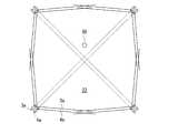
- FIG. 1is a perspective view showing an example of a hardware configuration of a robot system and a working environment of the robot system according to the first embodiment of the present invention.
- FIG. 2is a perspective view showing an operation of the robot body by the operator and a specific operation of a stereoscopic viewing target area to be stereoscopically viewed in detail.
- FIG. 3is a functional block diagram illustrating an example of a configuration of a control system of the robot system in FIG.
- FIGS. 4A to 4Dare schematic diagrams schematically illustrating a mode of adjusting a stereoscopic viewing target area to be stereoscopically viewed in detail.
- FIG. 5is a schematic diagram showing the relationship between the visual fields of the left-eye camera and the right-eye camera and the stereoscopic viewing target area where the operator performs stereoscopic viewing in detail.
- FIG. 6is a schematic diagram schematically illustrating image processing for extracting an image corresponding to a stereoscopic viewing target area in which the operator intends to perform stereoscopic viewing in detail.
- FIG. 7is a schematic diagram illustrating a relationship between a plurality of pairs of left-eye camera and right-eye camera operator according to the third embodiment of the present invention and a stereoscopic viewing target area in which a stereoscopic view is performed in detail.
- FIG. 1is a perspective view showing a hardware configuration of a robot system according to a first embodiment of the present invention and a work environment of the robot system.
- FIG. 2is a perspective view showing an operation of the robot body by the operator and a specific operation of a stereoscopic viewing target area to be stereoscopically viewed in detail.
- FIG. 3is a functional block diagram showing a configuration of a control system of the robot system of FIG.
- FIGS. 4A to 4Dare schematic diagrams schematically illustrating a mode of adjusting a stereoscopic viewing target area to be stereoscopically viewed in detail.
- FIG. 5is a schematic diagram showing the relationship between the visual fields of the left-eye camera and the right-eye camera and the stereoscopic viewing target area where the operator performs stereoscopic viewing in detail.
- a robot system 100includes a robot body 1 having a work unit 11 for performing a work, and a robot operation device for an operator 31 to operate the robot body 1. 2, a left-eye camera 3 and a right-eye camera 4 for capturing a left-eye image and a right-eye image, respectively, of a work area where the work unit 11 of the robot body 1 works; Display 5 for displaying a parallax image 43 for stereoscopic viewing by the operator, and the left-eye camera 3 and the right-eye viewing, in which the operator 31 tries to perform stereoscopic viewing with the parallax image 43 displayed on the stereoscopic display 5.
- An area operation device 6that operates to specify a stereoscopic viewing target area 50 in an absolute space in the common visual field 23 of the camera 4, and a robot that controls the operation of the robot body 1 in accordance with the operation of the robot operation device 2 G corresponding to the stereoscopic target area 50 specified by the operation of the area operation device 6 from the left-eye image and the right-eye image captured by the left-eye camera 3 and the right-eye camera 4.
- a stereoscopic display control unit 10that extracts images 51 and 52 and causes the stereoscopic display 5 to display the extracted images 51 and 52 as a parallax image 43 is provided.
- the configuration of the robot system 100will be specifically described.
- the robot system 100includes a robot body 1, a robot controller 2, a left-eye camera 3, a right-eye camera 4, a stereoscopic display 5, and an area controller 6. And stereoscopic glasses 7.
- the robot system 100further includes a controller 8.
- the controller 8includes a robot control unit 9 and a stereoscopic display control unit 10. That is, a pair of left-eye viewing camera 3 and right-eye viewing camera 4 is provided corresponding to one robot body 1.
- these elementswill be described in detail in order.
- the robot main body 1includes a working unit 11.
- the work unit 11only needs to be configured to perform a predetermined work.
- an end effectoris exemplified. Examples of the end effector include a hand, a painting gun, a welding gun, a nut runner, and the like.
- the working unit 11is a painting gun.
- the robot body 1 and the robot control unit 9constitute a robot.
- the robotis defined as, for example, "an intelligent mechanical system having three element technologies of a sensor, an intelligence / control system, and a drive system" (see “Points of the 2015 Ministry of Internal Affairs and Communications White Paper on Information and Communication").
- the robot main body 1is composed of, for example, industrial robots such as a vertical articulated robot, a horizontal articulated robot, a parallel link robot, a polar coordinate robot, a cylindrical coordinate robot, and a rectangular coordinate robot.
- industrial robotssuch as a vertical articulated robot, a horizontal articulated robot, a parallel link robot, a polar coordinate robot, a cylindrical coordinate robot, and a rectangular coordinate robot.
- the robot body 1is configured by a robot arm of a vertical articulated robot will be exemplified.
- the operating device 2may be any device that can operate the robot main body 1 (including the working unit 11) by the operation.
- the operating device 2may be configured by a master robot similar to the robot main body 1, and the robot main body 1 may be configured to be controlled as a slave robot.
- the operating device 2may be a joystick.
- the operating device 2may be a dedicated operating device customized for a specific use.
- the operating device 2is configured by a dedicated operating device customized as shown in FIG.
- the left-eye camera 3 and the right-eye camera 4are configured by digital cameras or analog cameras.
- the left-eye camera 3 and the right-eye camera 4are arranged such that the optical axes 3b and 4b are parallel to each other and have a predetermined interval. Further, the left-eye camera 3 and the right-eye camera 4 are arranged so as to be able to capture an image of a work area where the work unit 11 of the robot body 1 works on the work target 21.
- the left-eye camera 3 and the right-eye camera 4have predetermined angles of view 3a and 4a (field of view).
- the angle of view 3a, 4a of the left-eye camera 3 and the right-eye camera 4is, for example, 150 degrees or more and 360 degrees or less.
- the larger the angles of view 3a and 4athe wider the area (field of view) in the absolute space where the image can be captured, while the greater the distortion of the captured image (the closer to the periphery of the captured image the more the image is curved).
- the stereoscopic display 5includes, for example, a panel display.
- a well-known panel displaycan be used.
- the three-dimensional display 5is installed near the robot controller 2 so that the operator can easily see it.
- the area operation device 6is configured to be operable to specify the stereoscopic viewing target area 50 in the absolute space in the common visual field 23 of the left-eye camera 3 and the right-eye camera 4. It should be done.
- the shape of the stereoscopic viewing target area 50is arbitrary. More specifically, when the operator 31 operates the area operating device 6, the area operation device 6 outputs area specifying information including the position (for example, a representative position) of the stereoscopic viewing target area 50 in the absolute space in accordance with the operation.
- Output as The area operation device 6is constituted by, for example, a joystick.
- the area operation device 6 constituted by this joystickcan be tilted in any direction.
- a forward button (not shown) and a backward button (not shown)are provided at the tip of the joystick. Further, a plurality of buttons (hereinafter, referred to as area mode operation buttons (not shown)) for operating the mode of the stereoscopic viewing target area are provided at the tip of the joystick.
- the forward button, the backward button, and the area mode operation buttonare configured to be operated with the thumb while holding the area operation device 6 with a hand, and are configured to be pressed according to the pressing force.
- the area operation device 6is shown in a simplified manner by omitting the forward button, the backward button, and the area mode operation button.
- the robot control unit 9has a reference coordinate system of the robot body 1 (hereinafter, simply referred to as a reference coordinate system).
- the three-dimensional display control unit 10shares this reference coordinate system, and specifies a position in the absolute space using the reference coordinate system.
- position in absolute spacemeans a position in space defined by the reference coordinate system.
- the stereoscopic viewing target area 50is set such that the direction of extension of the optical axis of each of the left-eye camera 3 and the right-eye camera 4 extends from the distal end of the area operation device 6 to the proximal end.
- the forward button or the backward button of the area controller 6is pressed, in the stereoscopic viewing target area 50, the extending direction of each optical axis of the left-eye camera 3 and the right-eye camera 4 is the pushing direction of the forward button.
- the robotmoves forward or backward in the absolute space according to the amount of pushing of the forward button or the amount of pushing of the backward button.
- an initial setting positionis set.
- This initial setting positionis a reference position of the stereoscopic viewing target area 50 in the absolute space corresponding to the position of the working unit 11 of the robot body 1.
- the image of the stereoscopic viewing target area 50 located at the initial setting positionis displayed on the stereoscopic display 5 as the default parallax image 43 corresponding to the position of the working unit 11 of the robot body 1.
- This initial setting positionis appropriately set according to the work content. Here, for example, it is set at a position separated by a predetermined distance in the paint spraying direction of the paint gun 11.
- the “predetermined distance”is, for example, a distance suitable for painting the work 21.
- area specifying information other than the position of the stereoscopic viewing target area 50is output as an area operation signal. Area specifying information other than the position of the stereoscopic viewing target area 50 will be described later in detail.
- stereoscopic glasses 7can be used.
- the stereoscopic glasses 7are configured by attaching an optical filter to a frame in place of a lens of normal glasses.
- an optical filtera polarizing filter (polarizer), a liquid crystal shutter, or the like is used.
- polarizing filterpolarizer
- a wave plate that gives circularly polarized light having a rotation direction opposite to that of each scanning lineis attached to the display screen of the stereoscopic display 5, and the left-eye image 41 and the right-eye image are formed by odd and even scanning lines.
- the visual image 42is displayed.
- the stereoscopic glasses 7are provided with left and right polarization filters that pass only circularly polarized lights respectively corresponding to the left-eye image 41 and the right-eye image 42.
- the stereoscopic display 5is driven at a high speed, and the left-eye image 41 and the right-eye image 42 are alternately displayed in a time-division manner.
- the left and right liquid crystal shuttersare opened and closed, respectively, in synchronization with the time division display.
- the controller 8includes, for example, a processor and a memory.
- the controller 8controls the operation of the robot body 1 and controls the three-dimensional display of the three-dimensional display 5 by reading and executing a predetermined operation program stored in the memory by the processor.
- the controller 8is specifically, for example, a microcontroller, an MPU, an FPGA (Field Programmable Gate Array) , A PLC (Programmable Logic Controller), a logic circuit and the like.
- the controller 8includes a robot controller 9 and a stereoscopic display controller 10.
- the robot control unit 9 and the three-dimensional display control unit 10are functional blocks realized by the processor reading and executing a predetermined operation program stored in the memory, as described above.
- the controller 8includes a single controller that performs centralized control or a plurality of controllers that perform distributed control.
- the controller 8is configured by a single controller.
- the controller 8is configured by two controllers, and the robot controller 9 and the stereoscopic display controller are respectively controlled by the two controllers. 10 may be realized.
- the controller 8can be arranged at any place.
- the controller 8is arranged, for example, inside a base 12 that supports the robot body 1.
- the robot controller 2when the operator 31 operates the robot controller 2, the robot controller 2 outputs a robot operation signal to the robot controller 9.
- the robot controller 9controls the operation of the robot body 1 according to the input robot operation signal.
- the robot main body 1operates according to the operation.
- the robot control unit 9has the reference coordinate system as described above, and specifies the position of the robot main body 1 on the reference coordinate system and controls the operation of the robot main body 1.
- the stereoscopic display control unit 10controls operations such as turning on / off and focusing of the left-eye camera 3 and the right-eye camera 4.
- the left-eye viewing camera 3 and the right-eye viewing camera 4respectively capture an image of a work area where the working unit 11 of the robot body 1 works on the work target 21, and capture a left-eye view captured image 61 and a right-eye captured image.
- the visually captured image 62(see FIG. 6) is output to the stereoscopic display control unit 10.
- the area operation device 6outputs an area operation signal to the stereoscopic display control unit 10.
- the stereoscopic display control unit 10performs image processing on the input left-eye captured image 61 and right-eye captured image 63 according to the input area operation signal, and generates a parallax image 43. Then, an image display signal for displaying the generated parallax image is output to the stereoscopic display 5.
- the stereoscopic display 5displays the parallax image 43 according to the input image display signal.
- the left-eye viewing image 41 and the right-eye viewing image 42 constituting the parallax image 43are displayed side by side on the display screen.
- the left-eye viewing image 41 and the right-eye viewing image 42may be displayed on the display screen in an overlapping manner.
- the three-dimensional display control unit 10causes the three-dimensional display device 5 to display an initially set parallax image 43 corresponding to the position of the work unit 11 of the robot body 1.
- the parallax image 43can be displayed so as to follow the operation of the robot body 1.
- the robot bodyis not operated.
- An initial parallax image 43 corresponding to the position of the first working unit (painting gun) 11is displayed.
- the first predetermined conditionis that the work is started.
- the image of the stereoscopic viewing target area 50 in the absolute space corresponding to the position of the work unit 11 of the robot main body 1is displayed as the parallax image 43 of the initial setting.
- an image of the stereoscopic viewing target area 50 in the absolute space corresponding to the position of the working unit (painting gun) 11 of the robot body 1is displayed.
- ⁇ Circle around (2) ⁇As a second predetermined condition, it is specified that the area operation device 6 has not been operated for a predetermined time.
- the “predetermined time”is appropriately determined by calculation, experiment, simulation, or the like. With this configuration, the following operation and effect can be obtained.
- the parallax image 43 of the very narrow stereoscopic viewing area 50 of the work area of the robot body 1is displayed on the stereoscopic display 5, an area far from the currently displayed stereoscopic viewing area 50 is stereoscopically viewed.
- the direction in which the stereoscopic target area should be movedmay not be known. According to this configuration, if the area operation device 6 is not operated for a predetermined time for such a reason, the image of the stereoscopic viewing target area 50 in the absolute space corresponding to the position of the working unit 11 (painting gun) of the robot body 1 is displayed.
- the parallax imageis displayed on the stereoscopic display 5 as the default parallax image, the area far from the currently displayed stereoscopic target area 50 can be easily moved by moving the stereoscopic target area 50 from that point. Can be displayed as the stereoscopic viewing target area 50.
- the robot system 100is disposed, for example, in a work room 14.
- FIG. 1is drawn so as to see through the work room 14 for convenience.
- a lift 22 for suspending and transporting the work object 21is provided so as to pass above the work chamber 14.
- the work target 21is, for example, a link member constituting a robot arm of the articulated robot.
- the robot main body 1 of each robot system 100is constituted by a vertical articulated robot, and a coating gun as a working unit 11 is mounted at the tip. That is, in the work room 14, the link member as the work object 21 transported by the lift 22 is painted by the robot body 1.
- the work areais an area including the work object 21 that moves within the time when the painting work by the robot body 1 is completed, the surrounding area, and the work unit 11 of the robot body 1.
- the robot main body 1is provided on a base 12.
- a pair of left-eye camera 3 and right-eye camera 4is arranged beside the robot body 1.
- the pair of left-eye viewing camera 3 and right-eye viewing camera 4are arranged on the table so that their respective optical axes pass through a region through which the work object 21 suspended by the lift 22 passes.
- the pair of left-eye viewing camera 3 and right-eye viewing camera 4are arranged such that the work area where the work unit (painting gun) 11 of the robot body 1 works is within the field of view (angle of view).
- the pair of left-eye viewing camera 3 and right-eye viewing camera 4 and the tableare accommodated in a transparent case 13 so that paint does not adhere.
- FIG. 1shows the operation desks 16 and operation chairs 15 corresponding to only one robot system 100.
- a robot controller 2is provided on the right side of the operation chair 15.
- An area controller 6is provided on the left side of the operation chair 15.
- An operation desk 16is arranged in front of the operation chair 15.
- the three-dimensional display 5composed of a panel display is arranged.
- the operator 31sits on the operation chair 15, holds the robot controller 2 with the right hand, and holds the area controller 6 with the left hand.
- the operator 31wears the stereoscopic glasses 7 and stereoscopically views the parallax image 43 displayed on the stereoscopic display 5 through the stereoscopic glasses 7, while holding the robot operating device 2 and the area operating device 6 with the right hand and the left hand, respectively.
- ManipulateThen, the robot main body 1 operates according to the operation of the robot controller 2, and the parallax image 43 is displayed on the stereoscopic display 5 according to the operation of the area controller 6.
- FIG. 6is a schematic diagram schematically illustrating image processing for extracting an image corresponding to a stereoscopic viewing target area in which the operator intends to perform stereoscopic viewing in detail.
- the parallax image 43 of the stereoscopic viewing target area 50 located at the initial setting positionis displayed on the stereoscopic display 5 as the initial setting image.
- the operator 31operates the area operation device 6 with the left hand while operating the robot operation device 2 with the right hand.
- the operator 31operates the area operation device 6 (and the forward button or the backward button) so as to position the stereoscopic viewing target area 50 at a desired position. Then, this position information is output to the three-dimensional display control unit 10 as an area operation signal.
- the stereoscopic display control unit 10is specified by the position information from the left-eye captured image 61 and the right-eye captured image 62 input from the left-eye camera 3 and the right-eye camera, respectively.
- An image 51 and an image 52 corresponding to the position of the stereoscopic viewing target area 50are extracted.
- the extracted images 51 and 52are corrected so as to remove distortion of the image caused by, for example, the wide-angle lens.
- the image distortion of the extracted images 51 and 52has the same distortion level as the image captured by the standard lens.
- how much image distortion is removed by the correctionis arbitrary. What is necessary is just to correct the image distortion so that the operator 31 can accurately recognize the target to be stereoscopically viewed.
- the stereoscopic display control unit 10expands each of the corrected pair of images to a predetermined size to generate a left-eye viewing image 41 and a right-eye viewing image 42, and uses these as a parallax image 43, as a stereoscopic display 5. To be displayed.
- the operator 31stereoscopically views the parallax image 43 through the stereoscopic glasses 7.
- the robot body 1 in the common field of view of the pair of left-eye camera 3 and right-eye camera 4is moved.
- a desired directioncan be stereoscopically viewed.
- the operator 31simply operates the area operation device 6, and as if the operator 31 positions the head at the position of the pair of the left-eye camera 3 and the right-eye camera 4, and moves the face up, down, left and right. It is possible to look around the work area as if looking around at the work area. In addition, a desired part of the work area can be stereoscopically viewed in detail.
- the operator 31looks around the work area surrounding the operator, A desired part of the work area can be stereoscopically viewed in detail. For this reason, the operability of the robot main body 1 is improved as compared with the related art.
- the operator 31operates a plurality of area mode operation buttons of the area operation device 6.
- the stereoscopic display control unit 10changes the size of the stereoscopic target area 50.
- the stereoscopic viewing target area 50(specifically, images 51 and 52 corresponding to the stereoscopic viewing target area 50) viewed from the optical axis direction of the pair of left-eye viewing camera 3 and right-eye viewing camera 4.
- the sizeis changed, and the parallax image 43 reflecting this change is displayed on the stereoscopic display.
- the stereoscopic display control unit 10causes the image 51 to be displayed in accordance with the area specifying information for changing the parallax.
- the parallax with the image 52is changed, and the left-eye image 41 and the right-eye image 42 reflecting the changed parallax are displayed on the stereoscopic display 5.
- the stereoscopic display control unit 10causes the image 51 and the image 51 to be displayed in accordance with the area specifying information for specifying the zoom.
- the zoom 52is specified, and the stereoscopic display 5 displays the left-eye image 41 and the right-eye image 42 that are enlarged or reduced according to the specified zoom.
- This zoomis a pseudo zoom, and is performed by adjusting the magnification of the images 51 and 52 shown in FIG.
- the operator 31can stereoscopically view a desired part of the work area where the work unit 11 of the robot body 1 works in detail.
- the pair of left-eye cameras 3 and right-eye cameras 4are provided so that the directions of the optical axes can be respectively changed. It is a thing.
- This optical axis direction changing device(not shown) can be constituted by a known attitude changing device. Examples of the posture changing device include a small articulated robot, a driving device for a parabolic antenna, and the like.
- the operator 31can stereoscopically view a desired part of the work area of the robot body 1 in a wider range in detail.
- FIG. 7is a schematic diagram showing a relationship between a plurality of pairs of left-view camera and right-view camera operators according to the third embodiment and a stereoscopic viewing target area in which a stereoscopic view is performed in detail.
- a plurality of pairs (here, four pairs) of the left-eye camera 3 and the right-eye camera 4are arranged.
- the plurality of pairs of the left-eye camera 3 and the right-eye camera 4are arranged so as to surround a work area (not shown in FIG. 7) in which the work unit (painting gun) 11 of the robot body 1 works.
- the plurality of pairs of the left-eye camera 3 and the right-eye camera 4are arranged such that the common visual field 23 of each pair of the left-eye camera 3 and the right-eye camera 4 overlaps between adjacent pairs. Have been.
- the area operation device 6is provided with a camera selection button for selecting one of a plurality of pairs of the left-eye camera 3 and the right-eye camera 4.
- the stereoscopic display control unit 10displays the parallax image 43 captured by the left-eye viewing camera 3 and the right-eye viewing camera 4 of the selected pair on a stereoscopic display. 5 is displayed.
- the stereoscopic display control unit 10automatically switches the pair of the left-eye viewing camera 3 and the right-eye viewing camera 4 according to the position of the stereoscopic viewing target area 50 and displays the parallax images 43 on the stereoscopic display 5. May be displayed. In this case, for example, the stereoscopic display control unit 10 selects a pair of the left-eye viewing camera 3 and the right-eye viewing camera that are closest to the stereoscopic viewing target area 50 and have the closest optical axis.
- the operator 31can stereoscopically view a desired part of the work area in detail, as if going around the work area. Therefore, the operability of the robot body 1 is further improved.
- the stereoscopic display 5may be an HMD (Head Mounted Display) mounted on the head of the operator 31.
- HMDHead Mounted Display
- the robot system of the present inventionis useful as a robot system capable of operating the robot body while stereoscopically viewing a part of the work area in detail.
Landscapes
- Engineering & Computer Science (AREA)
- Multimedia (AREA)
- Signal Processing (AREA)
- Robotics (AREA)
- Mechanical Engineering (AREA)
- Physics & Mathematics (AREA)
- General Physics & Mathematics (AREA)
- Theoretical Computer Science (AREA)
- Manipulator (AREA)
- Geometry (AREA)
- Stereoscopic And Panoramic Photography (AREA)
- Closed-Circuit Television Systems (AREA)
- Testing, Inspecting, Measuring Of Stereoscopic Televisions And Televisions (AREA)
- Studio Devices (AREA)
Abstract
Description
Translated fromJapanese本発明は、ロボットシステムに関する。The present invention relates to a robot system.
立体表示装置に表示された作業対象の物体を見ながらマニピュレータを遠隔操作する技術が知られている(例えば、特許文献1参照)。A technique of remotely operating a manipulator while looking at a work target object displayed on a three-dimensional display device is known (for example, see Patent Document 1).
上記従来技術によれば、操作者が物体を立体的に捉えることができるので、マニピュレータの操作性が向上する。しかし、ロボット(マニピュレータ)を遠隔操作して作業する場合、操作者が、作業対象の物体、ロボットの作業部、及びそれらの周囲(以下、作業エリアという)の一部を詳しく立体視したい場合がある。しかし、上記従来技術では、固定された立体カメラの視野全体の画像しか表示されないので、操作者は作業エリアの一部を詳しく立体視することができなかった。According to the above-described conventional technology, the operator can three-dimensionally grasp the object, so that the operability of the manipulator is improved. However, when working remotely by operating a robot (manipulator), the operator sometimes wants to stereoscopically view the object to be worked, the working part of the robot, and a part of the surrounding area (hereinafter referred to as a working area) in detail. is there. However, in the above-described conventional technology, only the image of the entire field of view of the fixed stereoscopic camera is displayed, so that the operator cannot stereoscopically view a part of the work area in detail.
本発明は上記のような課題を解決するためになされたもので、作業エリアの一部を詳しく立体視しながらロボット本体を操作することが可能なロボットシステムを提供することを目的としている。The present invention has been made to solve the above-described problems, and has as its object to provide a robot system capable of operating a robot body while stereoscopically viewing a part of a work area in detail.
上記目的を達成するために、本発明のある形態(aspect)に係る、ロボットシステムは、作業を行う作業部を有するロボット本体と、操作者が前記ロボット本体を操作するためのロボット操作器と、前記ロボット本体の作業部が作業する作業エリアの左眼視撮像画像及び右眼視撮像画像をそれぞれ撮像する左眼視カメラ及び右眼視カメラと、前記操作者が両眼によって立体視するための視差画像を表示する立体表示器と、前記操作者が、前記立体表示器に表示される視差画像よって立体視しようとする、前記左眼視カメラ及び右眼視カメラの共通の視野における絶対空間上の立体視対象エリアを特定するよう操作するエリア操作器と、前記ロボット操作器の操作に応じて前記ロボット本体の動作を制御するロボット制御部と、前記左眼視カメラ及び右眼視カメラが撮像する前記左眼視撮像画像及び右眼視撮像画像から前記エリア操作器の操作によって特定された前記立体視対象エリアに対応する画像をそれぞれ抽出し、この抽出した画像を、前記立体表示器に前記視差画像として表示させる立体表示制御部と、を備える。ここで、「絶対空間」とは、左眼視カメラ及び右眼視カメラが存在する空間を意味し、「絶対空間上の位置」は、所定の座標系、例えば、ロボット本体の基準座標系によって特定される。「左眼視カメラ及び右眼視カメラ」とは、互いに平行で所定の間隔を有する一対の光軸を有する一対のカメラを意味する。「左眼視カメラ及び右眼視カメラの視野」とは、左眼視カメラ及び右眼視カメラの画角内の空間を意味する。In order to achieve the above object, according to an aspect of the present invention, a robot system includes a robot body having a working unit for performing a task, a robot operation device for an operator to operate the robot body, A left-eye camera and a right-eye camera, each of which captures a left-eye image and a right-eye image of a work area where a work unit of the robot body works, and for the operator to perform stereoscopic viewing with both eyes. A stereoscopic display that displays a parallax image, and the operator attempts to stereoscopically view the parallax image displayed on the stereoscopic display, in an absolute space in a common visual field of the left-eye camera and the right-eye camera. An area operation device that operates to specify a stereoscopic target area of the robot, a robot control unit that controls the operation of the robot body in accordance with the operation of the robot operation device, and the left-eye camera An image corresponding to the stereoscopic target area specified by the operation of the area operation device is extracted from the left-eye captured image and the right-eye captured image captured by the right-eye camera, and the extracted image is extracted. A stereoscopic display control unit that causes the stereoscopic display to display the parallax image. Here, the “absolute space” means a space where the left-eye camera and the right-eye camera exist, and the “position in the absolute space” is determined by a predetermined coordinate system, for example, a reference coordinate system of the robot body. Specified. The “left-eye camera and right-eye camera” mean a pair of cameras having a pair of optical axes that are parallel to each other and have a predetermined interval. The “field of view of the left-eye camera and the right-eye camera” means a space within the angle of view of the left-eye camera and the right-eye camera.
この構成によれば、操作者がエリア操作器を操作して、立体表示器に表示される視差画像よって立体視しようとする立体視対象エリアを特定すると、立体表示制御部が、左眼視カメラ及び右眼視カメラが撮像する左眼視撮像画像及び右眼視撮像画像からエリア操作器の操作によって特定された立体視対象エリアに対応する画像をそれぞれ抽出し、この抽出した画像を、立体表示器に視差画像として表示させるので、操作者は、ロボット本体の作業部が作業する作業エリアの所望の一部を詳しく立体視することができる。According to this configuration, when the operator operates the area operation device and specifies the stereoscopic viewing target area to be stereoscopically viewed based on the parallax image displayed on the stereoscopic display device, the stereoscopic display control unit sets the left-eye camera And extracting an image corresponding to the stereoscopic target area specified by the operation of the area operation device from the left-eye captured image and the right-eye captured image captured by the right-eye camera, and displaying the extracted image in a three-dimensional display. The operator can display a desired part of the work area where the work unit of the robot main body works in detail stereoscopically because the display unit displays the parallax image as a parallax image.
前記立体表示制御部は、前記エリア操作器が操作されていない場合に、前記左眼視カメラ及び右眼視カメラが撮像する前記左眼視撮像画像及び右眼視撮像画像から前記ロボット本体の前記作業部の位置に対応する絶対空間上の立体視対象エリアの画像をそれぞれ抽出し、この抽出した画像を、初期設定の前記視差画像として前記立体表示器に表示させてもよい。The three-dimensional display control unit, when the area operation device is not operated, the left-eye image and the right-eye image captured by the left-eye camera and the right-eye camera, An image of the stereoscopic viewing target area on the absolute space corresponding to the position of the work unit may be extracted, and the extracted image may be displayed on the stereoscopic display as the initially set parallax image.
この構成によれば、例えば、作業の開始時に、ロボット本体の作業部の位置に対応する絶対空間上の立体視対象エリアの画像を初期設定の視差画像として表示することにより、ロボット本体の動作に追従して、ロボット本体の作業部の位置に対応する絶対空間上の立体視対象エリアの画像が表示されるので、ロボット操作器によってロボット本体を操作しながらエリア操作器を操作して、速やかにロボット本体の作業部が作業する作業エリアの所望の一部を詳しく立体視することができる。According to this configuration, for example, at the start of the work, the image of the stereoscopic viewing target area in the absolute space corresponding to the position of the working unit of the robot body is displayed as the default parallax image, so that the operation of the robot body is Following, the image of the stereoscopic viewing target area in the absolute space corresponding to the position of the working part of the robot body is displayed, so operate the area operation device while operating the robot body with the robot operation device, and quickly A desired part of the work area where the work section of the robot body works can be stereoscopically viewed in detail.
また、立体表示器には作業エリアのうちのごく狭い立体視対象エリアの視差画像が表示されるので、現在表示されている立体視対象エリアから遠く離れたエリアを立体視対象エリアとして表示させたい場合に、立体視対象エリアを移動させるべき方向が判らなくなる場合がある。この構成によれば、そのような理由でエリア操作器が操作されないと、ロボット本体の作業部の位置に対応する絶対空間上の立体視対象エリアの画像が初期設定の視差画像として立体表示器に表示されるので、そこを出発点として、立体視対象エリアを移動させることによって、現在表示されている立体視対象エリアから遠く離れたエリアを容易に立体視対象エリアとして表示させることができる。In addition, since a parallax image of a very narrow stereoscopic viewing target area of the work area is displayed on the stereoscopic display, it is desirable to display an area far from the currently displayed stereoscopic viewing target area as the stereoscopic viewing target area. In such a case, the direction in which the stereoscopic viewing target area should be moved may not be known. According to this configuration, if the area operation device is not operated for such a reason, the image of the stereoscopic viewing target area in the absolute space corresponding to the position of the working unit of the robot body is displayed on the stereoscopic display as the default parallax image. Since the displayed area is displayed, the area far from the currently displayed stereoscopic viewing area can be easily displayed as the stereoscopic viewing area by moving the stereoscopic viewing area starting there.
また、前記エリア操作器は、前記立体視対象エリアの大きさ、前記立体視対象エリアの位置、前記視差画像の視差、及び前記視差画像の拡大・縮小の少なくともいずれかを調整するよう操作することが可能であり、前記立体表示制御部は、前記エリア操作器の操作に応じて前記左眼視撮像画像及び右眼視撮像画像の画像処理を行い、前記立体視対象エリアの大きさ、前記立体視対象エリアの位置、前記視差画像の視差、及び前記視差画像の拡大・縮小の少なくともいずれかが調整された前記視差画像を前記立体表示器に表示させてもよい。The area operation device may be operated to adjust at least one of a size of the stereoscopic target area, a position of the stereoscopic target area, parallax of the parallax image, and enlargement / reduction of the parallax image. The stereoscopic display control unit performs image processing of the left-eye captured image and the right-eye captured image in accordance with the operation of the area operation device, the size of the stereoscopic target area, the stereoscopic The stereoscopic display may display the parallax image in which at least one of the position of the parallax target area, the parallax of the parallax image, and the enlargement / reduction of the parallax image has been adjusted.
この構成によれば、ロボット本体の作業部が作業する作業エリアの所望の一部を、所望の態様で詳しく立体視することができる。According to this configuration, a desired part of the work area where the work unit of the robot body works can be stereoscopically viewed in a desired manner in detail.
前記左眼視カメラ及び右眼視カメラの画角が150度以上且つ360度以下であってもよい。The angles of view of the left-eye camera and the right-eye camera may be 150 degrees or more and 360 degrees or less.
この構成によれば、ロボット本体の作業部が作業する作業エリアが広い場合でも、操作者は、当該作業エリアの所望の一部を詳しく立体視することができる。According to this configuration, even when the work area where the work unit of the robot main body works is wide, the operator can stereoscopically view a desired part of the work area in detail.
前記立体表示制御部は、前記前記左眼視撮像画像及び右眼視撮像画像から抽出した画像を、広角レンズに起因する画像歪み除去するよう補正し、この補正した画像を前記立体表示器に前記視差画像として表示させてもよい。The stereoscopic display control unit corrects an image extracted from the left-eye captured image and the right-eye captured image to remove image distortion caused by a wide-angle lens, and outputs the corrected image to the stereoscopic display. It may be displayed as a parallax image.
この構成によれば、標準レンズで撮像した画像と同程度の歪みレベルの視差画像によって、広い作業エリアの一部を詳しく立体視することができる。According to this configuration, a part of a wide work area can be stereoscopically viewed in detail with a parallax image having a distortion level substantially equal to that of an image captured by a standard lens.
複数対の前記左眼視カメラ及び右眼視カメラが、前記ロボット本体1の作業部が作業する作業エリアを取り囲むように配置されており、前記立体表示制御部は、選択された対の左眼視カメラ3及び右眼視カメラ4に対応する視差画像を立体表示器に表示してもよい。A plurality of pairs of the left-eye camera and the right-eye camera are arranged so as to surround a work area where the work unit of the robot
この構成によれば、操作者は、あたかも作業エリアの周囲を周回するようにして、当該作業エリアの所望の一部を詳しく立体視することができる。According to this configuration, the operator can stereoscopically view a desired part of the work area in detail, as if going around the work area.
本発明は、作業エリアの一部を詳しく立体視しながらロボット本体を操作することが可能なロボットシステムを提供できるという効果を奏する。The present invention has an effect that it is possible to provide a robot system capable of operating the robot body while stereoscopically viewing a part of the work area in detail.
以下、本発明の好ましい実施の形態を、図面を参照しながら説明する。なお、以下では全ての図を通じて同一又は相当する要素には同一の参照符号を付して、その重複する説明を省略する。また、以下の図は、本発明を説明するための図であるので、本発明と無関係な要素が省略される場合、誇張及び簡略化のため寸法が不正確である場合、複数の図が互いに一致しない場合等がある。また、本発明は、以下の実施形態に限定されない。Hereinafter, preferred embodiments of the present invention will be described with reference to the drawings. In the following, the same or corresponding elements are denoted by the same reference symbols throughout the drawings, and redundant description will be omitted. In addition, the following drawings are diagrams for explaining the present invention, and when elements unrelated to the present invention are omitted, dimensions are inaccurate for exaggeration and simplification, a plurality of drawings are There are cases where they do not match. Further, the present invention is not limited to the following embodiments.
(実施形態1)
[構成]
図1は、本発明の実施形態1に係るロボットシステムのハードウェアの構成及び当該ロボットシステムの作業環境を示す斜視図である。図2は、操作者によるロボット本体の操作及び詳しく立体視しようとする立体視対象エリアの特定操作の様子を示す斜視図である。図3は、図1のロボットシステムの制御系統の構成を示す機能ブロック図である。図4(a)~(d)は、詳しく立体視しようとする立体視対象エリアの調整の態様を模式的に示す模式図である。図5は、左眼視カメラ及び右眼視カメラの視野と操作者が詳しく立体視しようする立体視対象エリアとの関係を示す模式図である。(Embodiment 1)
[Constitution]
FIG. 1 is a perspective view showing a hardware configuration of a robot system according to a first embodiment of the present invention and a work environment of the robot system. FIG. 2 is a perspective view showing an operation of the robot body by the operator and a specific operation of a stereoscopic viewing target area to be stereoscopically viewed in detail. FIG. 3 is a functional block diagram showing a configuration of a control system of the robot system of FIG. FIGS. 4A to 4D are schematic diagrams schematically illustrating a mode of adjusting a stereoscopic viewing target area to be stereoscopically viewed in detail. FIG. 5 is a schematic diagram showing the relationship between the visual fields of the left-eye camera and the right-eye camera and the stereoscopic viewing target area where the operator performs stereoscopic viewing in detail.
図1乃至図3及び図5を参照すると、本実施形態に係るロボットシステム100は、作業を行う作業部11を有するロボット本体1と、操作者31がロボット本体1を操作するためのロボット操作器2と、ロボット本体1の作業部11が作業する作業エリアの左眼視撮像画像及び右眼視撮像画像をそれぞれ撮像する左眼視カメラ3及び右眼視カメラ4と、操作者31が両眼によって立体視するための視差画像43を表示する立体表示器5と、操作者31が、立体表示器5に表示される視差画像43よって立体視しようとする、左眼視カメラ3及び右眼視カメラ4の共通の視野23における絶対空間上の立体視対象エリア50を特定するよう操作するエリア操作器6と、ロボット操作器2の操作に応じてロボット本体1の動作を制御するロボット制御部9と、左眼視カメラ3及び右眼視カメラ4が撮像する左眼視撮像画像及び右眼視撮像画像からエリア操作器6の操作によって特定された立体視対象エリア50に対応する画像51,52をそれぞれ抽出し、この抽出した画像51,52を、立体表示器5に視差画像43として表示させる立体表示制御部10と、を備える。以下、ロボットシステム100の構成を具体的に説明する。Referring to FIG. 1 to FIG. 3 and FIG. 5, a
<ハードウェアの構成>
図1及び図2を参照すると、ロボットシステム100は、ロボット本体1と、ロボット操作器2と、左眼視カメラ3と、右眼視カメラ4と、立体表示器5と、エリア操作器6と、立体視メガネ7と、を備える。図3を参照すると、ロボットシステム100は、さらに、制御器8を備える。制御器8は、ロボット制御部9と立体表示制御部10とを含む。つまり、1台のロボット本体1に対応して、一対の左眼視カメラ3及び右眼視カメラ4が設けられる。以下、これらの要素を順に詳しく説明する。<Hardware configuration>
Referring to FIGS. 1 and 2, the
{ロボット本体1}
ロボット本体1は、作業部11を備える。作業部11は、所定の作業を行うよう構成されていればよい。作業部11として、エンドフェクタが例示される。エンドエフェクタとして、ハンド、塗装ガン、溶接ガン、ナットランナー等が例示される。ここでは、作業部11は、塗装ガンである。ロボット本体1とロボット制御部9とがロボットを構成する。ロボットは、例えば、「センサ、知能・制御系、駆動系の3つの要素技術を有する、知能化した機械システム」と定義される(「総務省平成27年版情報通信白書のポイント」参照)。具体的には、ロボット本体1は、例えば、垂直多関節型ロボット、水平多関節型ロボット、パラレルリンク型ロボット、極座標ロボット、円筒座標型ロボット、直角座標型ロボット等の産業用ロボットで構成される。以下では、ロボット本体1が、垂直多関節型ロボットのロボットアームで構成される場合が例示される。{Robot 1}
The robot
{操作器2}
操作器2は、その操作によって、ロボット本体1(作業部11を含む)を操作できるものであればよい。例えば、操作器2をロボット本体1と相似のマスターロボットで構成し、ロボット本体1をスレーブロボットとして制御するように構成してもよい。また、操作器2がジョイスティックであってもよい。また、操作器2が、特定の用途にカスタマイズされた専用の操作器であってもよい。ここでは、操作器2は、図2に示すようにカスタマイズされた専用の操作器で構成される。{Operation device 2}
The operating
{左眼視カメラ3及び右眼視カメラ4}
図1及び図5を参照すると、左眼視カメラ3及び右眼視カメラ4は、デジタルカメラ又はアナログカメラで構成される。左眼視カメラ3及び右眼視カメラ4は、各々の光軸3b,4bが互いに平行で所定の間隔を有するように配置される。また、左眼視カメラ3及び右眼視カメラ4は、ロボット本体1の作業部11が作業対象21に対して作業する作業エリアを撮像することが可能なように配置される。左眼視カメラ3及び右眼視カメラ4は、所定の画角3a,4a(視野)を有する。左眼視カメラ3及び右眼視カメラ4の画角3a,4aは、例えば、150度以上360度以下とされる。画角3a,4aが大きくなる程撮像可能な絶対空間上のエリア(視野)が広くなる一方、撮像画像の歪(撮像画像の周辺に近い部分程画像が彎曲する)が大きくなる。{
Referring to FIGS. 1 and 5, the left-
{立体表示器5}
図1及び図2を参照すると、立体表示器5は、例えば、パネルディスプレイで構成される。パネルディスプレイとして公知のものを使用することができる。立体表示器5は、操作者が見易いようにロボット操作器2の近傍に設置される。{3D display 5}
Referring to FIGS. 1 and 2, the
{エリア操作器6}
図2及び図5を参照すると、エリア操作器6は、左眼視カメラ3及び右眼視カメラ4の共通の視野23における絶対空間上の立体視対象エリア50を特定するよう操作できるように構成されておればよい。なお、立体視対象エリア50の形状は任意である。具体的には、エリア操作器6は、操作者31が操作すると、その操作に応じて、絶対空間上の立体視対象エリア50の位置(例えば、代表位置)を含むエリア特定情報をエリア操作信号として出力する。エリア操作器6は、例えば、ジョイスティックで構成される。このジョイスティックで構成されるエリア操作器6は、任意の方向に傾けることができる。ジョイスティックの先端部には、前進ボタン(図示せず)及び後退ボタン(図示せず)が設けられている。さらに、ジョイスィックの先端部には、立体視対象エリアの態様を操作するための複数のボタン(以下、エリア態様操作ボタンという(図示せず))が設けられている。前進ボタン、後退ボタン、及びエリア態様操作ボタンは、エリア操作器6を手で握った状態において親指で操作するように構成され、押圧力に応じて押し込まれるように構成される。なお、図2には、エリア操作器6が、前進ボタン、後退ボタン、及びエリア態様操作ボタンを省略して簡略化された態様で示されている。{Area controller 6}
Referring to FIGS. 2 and 5, the
ロボット制御部9は、ロボット本体1の基準座標系(以下、単に基準座標系という)を持っている。立体表示制御部10は、この基準座標系を共有しており、絶対空間上の位置を、この基準座標系によって特定する。以下、「絶対空間上の位置」とは、基準座標系によって規定される空間上の位置を意味する。エリア操作器6が直立姿勢をとるとき、エリア操作器6が絶対空間上に特定する立体視対象エリア50の位置は移動しない。そして、エリア操作器6を傾けるように操作すると、この立体視対象エリア50は、左眼視カメラ3及び右眼視カメラ4のそれぞれの光軸の延伸方向がエリア操作器6の先端から基端に向かう方向であると仮定した場合における当該エリア操作器6の傾いた方向に傾き量に応じて、絶対空間上を移動する。また、エリア操作器6の前進ボタン又は後退ボタンを押し込むと、立体視対象エリア50は、左眼視カメラ3及び右眼視カメラ4のそれぞれの光軸の延伸方向が前進ボタンの押し込み方向であると仮定した場合における前進ボタンの押し込み量又は後退ボタンの押し込み量に応じて、絶対空間上を前進又は後退する。The
立体視対象エリア50には、初期設定位置が設定される。この初期設定位置は、ロボット本体1の作業部11の位置に対応する絶対空間上の立体視対象エリア50の基準位置とされる。この初期設定位置に位置する立体視対象エリア50の画像が、ロボット本体1の作業部11の位置に対応する初期設定の視差画像43として立体表示器5に表示される。この初期設定位置は、作業内容に応じて、適宜設定される。ここでは、例えば、塗装ガン11の塗料噴射方向に所定距離だけ離れた位置に設定される。この「所定距離」は、例えば、作業対象21を塗装するのに適した距離とされる。初期 In the stereoscopic
エリア態様操作ボタンは、操作者31が操作すると、立体視対象エリア50の位置以外のエリア特定情報をエリア操作信号として出力する。立体視対象エリア50の位置以外のエリア特定情報については、後で詳しく説明する。When the
{立体視メガネ7}
図2を参照すると、立体視メガネ7は、市販のものを用いることができる。立体視メガネ7は、フレームに、通常のメガネのレンズに代えて光学フィルタが取り付けられて構成される。光学フィルタとして、偏光フィルタ(偏光子)、液晶シャッタ等が用いられる。偏光フィルタが用いられる場合、立体表示器5の表示画面に走査線毎に回転方向が逆の円偏光を与える波長板が張り付けられ、奇数と偶数との走査線によって左眼視画像41及び右眼視画像42が表示される。立体視メガネ7には、この左眼視画像41及び右眼視画像42にそれぞれ対応する円偏光のみを通過させる左右の偏光フィルタが取り付けられる。{Stereoscopic glasses 7}
Referring to FIG. 2, commercially available
液晶シャッタが用いられる場合、立体表示器5が高速駆動されて、左眼視画像41及び右眼視画像42が時分割で交互に表示される。この時分割表示に同期して、左右の液晶シャッタがそれぞれ開閉される。When the liquid crystal shutter is used, the
{制御器8}
制御器8は、例えば、プロセッサとメモリとを備える。制御器8は、メモリに格納された所定の動作プログラムをプロセッサが読み出して実行することにより、ロボット本体1の動作を制御し、且つ、立体表示器5の立体表示を制御する。制御器8は、具体的には、例えば、マイクロコントローラ、MPU、FPGA(Field Programmable Gate Array)
、PLC(Programmable Logic Controller)、論理回路等で構成される。{Controller 8}
The
, A PLC (Programmable Logic Controller), a logic circuit and the like.
制御器8は、ロボット制御部9及び立体表示制御部10を含む。ロボット制御部9及び立体表示制御部10は、上述のように、メモリに格納された所定の動作プログラムをプロセッサが読み出して実行することにより実現される機能ブロックである。The
制御器8は、集中制御を行う単独の制御器又は分散制御をする複数の制御器で構成される。制御器8は、ここでは、単独の制御器で構成されるが、例えば、制御器8を2つの制御器で構成し、これら2つの制御器によって、それぞれ、ロボット制御部9及び立体表示制御部10を実現してもよい。The
制御器8は、任意の場所に配置することができる。制御器8は、例えば、ロボット本体1を支持する基台12の内部に配置される。The
<制御系統の構成>
図3を参照すると、ロボット操作器2は、操作者31が操作すると、ロボット操作信号をロボット制御部9に出力する。ロボット制御部9は、入力されるロボット操作信号に従って、ロボット本体1の動作を制御する。これにより、操作者31が操作器2を操作すると、その操作に従って、ロボット本体1が動作する。ロボット制御部9は、上述のように基準座標系を持っており、基準座標系上でロボット本体1の位置を特定して、ロボット本体1の動作を制御する。<Configuration of control system>
Referring to FIG. 3, when the
立体表示制御部10は、左眼視カメラ3及び右眼視カメラ4のオンオフ、合焦等の動作を制御する。一方、左眼視カメラ3及び右眼視カメラ4は、それぞれ、ロボット本体1の作業部11が作業対象21に対して作業する作業エリアを撮像し、撮像した左眼視撮像画像61及び右眼視撮像画像62(図6参照)を立体表示制御部10に出力する。また、エリア操作器6は、操作者31が操作すると、エリア操作信号を立体表示制御部10に出力する。立体表示制御部10は、入力される左眼視撮像画像61及び右眼視撮像画像63を、入力されるエリア操作信号に従って画像処理し、視差画像43を生成する。そして、この生成した視差画像を表示するための画像表示信号を立体表示器5に出力する。The stereoscopic
立体表示器5は、入力される画像表示信号に従って視差画像43を表示する。視差画像43を構成する左眼視画像41及び右眼視画像42は、ここでは、表示画面上に並べて表示される。なお、左眼視画像41及び右眼視画像42は、表示画面上に重ねて表示されてもよい。The
さらに、立体表示制御部10は、エリア操作器6が操作されていない場合には、ロボット本体1の作業部11の位置に対応する初期設定の視差画像43を、立体表示器5に表示させる。これにより、ロボット本体1の動作に追従するように視差画像43を表示することができる。但し、操作者31のエリア操作器6の操作による立体視対象エリア50の選択を邪魔しないように、エリア操作器6が操作されていないことに加えて所定の条件を満たす場合にのみ、ロボット本体1の作業部(塗装ガン)11の位置に対応する初期設定の視差画像43が表示される。Further, when the
ここでは、第1の所定条件として、作業の開始時であることが規定される。この構成によれば、作業の開始時に、ロボット本体1の作業部11の位置に対応する絶対空間上の立体視対象エリア50の画像が初期設定の視差画像43として表示されることにより、ロボット本体1の動作に追従して、ロボット本体1の作業部(塗装ガン)11の位置に対応する絶対空間上の立体視対象エリア50の画像が表示されるので、操作者31が、ロボット操作器2によってロボット本体1を操作しながらエリア操作器6を操作して、速やかにロボット本体1の作業部11が作業する作業エリアの所望の一部を詳しく立体視することができる。Here, the first predetermined condition is that the work is started. According to this configuration, at the start of the operation, the image of the stereoscopic
また、第2の所定の条件として、所定時間、エリア操作器6が操作されていないことが規定される。「所定時間」は、計算、実験、シミュレーション等により適宜決定される。この構成により、以下のような作用効果が奏される。{Circle around (2)} As a second predetermined condition, it is specified that the
立体表示器5にはロボット本体1の作業エリアのうちのごく狭い立体視対象エリア50の視差画像43が表示されるので、現在表示されている立体視対象エリア50から遠く離れたエリアを立体視対象エリアとして表示させたい場合に、立体視対象エリアを移動させるべき方向が判らなくなる場合がある。この構成によれば、そのような理由でエリア操作器6が所定時間操作されないと、ロボット本体1の作業部11(塗装ガン)の位置に対応する絶対空間上の立体視対象エリア50の画像が初期設定の視差画像として立体表示器5に表示されるので、そこを出発点として、立体視対象エリア50を移動させることによって、現在表示されている立体視対象エリア50から遠く離れたエリアを容易に立体視対象エリア50として表示させることができる。Since the
[作業環境]
図1を参照すると、ロボットシステム100は、例えば、作業室14内に配置される。図1は、便宜上、作業室14を透視するように描かれている。この作業室14の上部を通過するように、作業対象21を吊り下げて搬送するリフト22が設けられている。作業対象21は、例えば、多関節ロボットのロボットアームを構成するリンク部材である。このリフト22に沿って、例えば、2つのロボットシステム100が配置されている。各ロボットシステム100のロボット本体1は垂直多関節型ロボットで構成されていて、先端部に作業部11としての塗装ガンが装着されている。つまり、この作業室14においては、リフト22によって搬送される作業対象21としてのリンク部材が、ロボット本体1によって塗装される。そして、ロボット本体1による塗装作業が完了する時間内に移動する作業対象21と、その周囲と、ロボット本体1の作業部11とを含むエリアが作業エリアである。ロボット本体1は、基台12の上に設けられている。[Work environment]
Referring to FIG. 1, the
ロボット本体1の横に一対の左眼視カメラ3及び右眼視カメラ4が配置されている。一対の左眼視カメラ3及び右眼視カメラ4は、置台の上に、それぞれの光軸が、リフト22に吊り下げられた作業対象21が通過する領域を通るように配置されている。換言すると、一対の左眼視カメラ3及び右眼視カメラ4は、ロボット本体1の作業部(塗装ガン)11が作業する作業エリアが視野(画角)内に収まるように配置されている。一対の左眼視カメラ3及び右眼視カメラ4と置台は、塗料が付着しないように、透明なケース13内に収容されている。一 対 A pair of left-
作業室14の隣の部屋に操作机16及び操作椅子15が配置されている。これらの操作机16及び操作椅子15は、ロボットシステム100毎に配置されているが、図1には、1つのロボットシステム100のみに対応する操作机16及び操作椅子15が示されている。操作 An
図1及び図2を参照すると、例えば、操作椅子15の右側部には、ロボット操作器2が設けられている。また、操作椅子15の左側部にはエリア操作器6が設けられている。そして、操作椅子15の前方に操作机16が配置されている。操作机16の上には、パネルディスプレイで構成される立体表示器5が配置されている。操作者31は、操作椅子15に座り、右手でロボット操作器2を把持し、左手でエリア操作器6を把持する。操作者31は、立体視メガネ7を装着し、立体表示器5に表示される視差画像43を立体視メガネ7を通して立体視しながら、ロボット操作器2及びエリア操作器6をそれぞれ右手及び左手で操作する。すると、ロボット操作器2の操作に応じてロボット本体1が動作し、エリア操作器6の操作に応じて、立体表示器5に視差画像43が表示される。及 び Referring to FIGS. 1 and 2, for example, a
[動作]
次に、以上のように構成されたロボットシステム100の動作を図1乃至図6を参照しながら説明する。図6は、操作者が詳しく立体視しようとする立体視対象エリアに対応する画像を抽出する画像処理を模式的に示す模式図である。[motion]
Next, the operation of the
作業が開始されると、立体表示器5に、初期設定位置に位置する立体視対象エリア50の視差画像43が初期設定画像として表示される。When the operation is started, the
操作者31は、右手でロボット操作器2を操作しながら、左手でエリア操作器6を操作する。The
操作者31は、まず、立体視対象エリア50を所望の位置に位置させるよう、エリア操作器6(及び前進ボタン又は後退ボタン)を操作する。すると、この位置情報がエリア操作信号として立体表示制御部10に出力される。First, the
図6を参照すると、立体表示制御部10は、左眼視カメラ3及び右眼視カメラからそれぞれ入力される左眼視撮像画像61及び右眼視撮像画像62から、この位置情報によって特定される立体視対象エリア50の位置にそれぞれ対応する画像51及び画像52を抽出する。そして、この抽出した画像51及び画像52を、例えば、広角レンズに起因する画像の歪を除去するよう補正する。これにより、この抽出した画像51及び画像52の画像歪が、標準レンズで撮像した画像と同程度の歪みレベルになる。但し、補正によってどの程度画像歪を除去するかは、任意である。操作者31が、立体視する対象を正確に視認できる程度に画像歪を補正すればよい。Referring to FIG. 6, the stereoscopic
立体表示制御部10は、補正した一対の画像を、それぞれ、所定の大きさに拡大して左眼視画像41及び右眼視画像42を生成し、これらを視差画像43として、立体表示器5に表示させる。この視差画像43を操作者31が、立体視メガネ7を通して、立体視する。The stereoscopic
操作者31が、図4(a)に示すように、所望の方向にエリア操作器6を傾けると、一対の左眼視カメラ3及び右眼視カメラ4の共通の視野内のロボット本体1の作業エリアにおいて、所望の方向を立体視することができる。これにより、操作者31は、エリア操作器6を操作するだけで、あたかも、操作者31が一対の左眼視カメラ3及び右眼視カメラ4の位置に頭部を位置させて顔を上下左右に振り向けて作業エリアを見回すように、作業エリアを見回すことができる。しかも、その作業エリアのうちの所望の一部のエリアを詳しく立体視することができる。特に、例えば、一対の左眼視カメラ3及び右眼視カメラ4の画角(視野)が360度である場合、操作者31は、あたかも、自分を取り巻く作業エリアをぐるりと見回すようにして、その作業エリアのうちの所望の一部のエリアを詳しく立体視することができる。このため、ロボット本体1の操作性が、従来に比べて、向上する。When the
次に、操作者31は、エリア操作器6の複数のエリア態様操作ボタンを操作する。Next, the
例えば、操作者31が、図4(b)に示すように、立体視対象エリア変更用のエリア態様操作ボタンを操作すると、立体表示制御部10は、この立体視対象エリア50の大きさを変更するエリア特定情報に従って、一対の左眼視カメラ3及び右眼視カメラ4の光軸方向から見た立体視対象エリア50(具体的には立体視対象エリア50に対応する画像51,52)の大きさを変更し、この変更を反映した視差画像43を立体表示器に表示させる。For example, when the
また、例えば、操作者31が、図4(c)に示すように、視差変更用のエリア態様操作ボタンを操作すると、立体表示制御部10は、この視差を変更するエリア特定情報に従って画像51と画像52との視差を変更し、この変更した視差を反映した左眼視画像41及び右眼視画像42を立体表示器5に表示させる。Further, for example, when the
また、例えば、操作者31が、図4(d)に示すように、ズーム用のエリア態様操作ボタンを操作すると、立体表示制御部10は、このズームを特定するエリア特定情報に従って画像51及び画像52のズームを特定し、この特定したズームに応じて拡大又は縮小した左眼視画像41及び右眼視画像42を立体表示器5に表示させる。このズームは、疑似ズームであり、図6に示す画像51及び画像52の拡大率を調整することによって行われる。Further, for example, when the
これにより、ロボット本体1の作業部11が作業する作業エリアの所望の一部を、所望の態様で詳しく立体視することができる。This allows a desired part of the work area where the
以上に説明したように、本実施形態によれば、操作者31は、ロボット本体1の作業部11が作業する作業エリアの所望の一部を詳しく立体視することができる。As described above, according to the present embodiment, the
(実施形態2)
本発明の実施形態2は、実施の形態1のロボットシステム100において、一対の左眼視カメラ3及び右眼視カメラ4が、それぞれ、光軸の方向を変更することが可能なように設けられたものである。この光軸方向変更装置(図示せず)は周知の姿勢変更装置で構成することができる。姿勢変更装置として、小型の多関節ロボット、パラボラアンテナの駆動装置等が例示される。(Embodiment 2)
In the second embodiment of the present invention, in the
このような本実施形態によれば、操作者31が、より広範囲なロボット本体1の作業エリアの所望の一部を詳しく立体視することができる。According to this embodiment, the
(実施形態3)
本発明の実施形態3は、以下の点で実施形態1と相違し、その他の点は実施形態1と同様である。以下、この相違点を説明する。(Embodiment 3)
The third embodiment of the present invention differs from the first embodiment in the following points, and the other points are the same as the first embodiment. Hereinafter, this difference will be described.
図7は、実施形態3における複数対の左眼視カメラ及び右眼視カメラ操作者が詳しく立体視しようする立体視対象エリアとの関係を示す模式図である。FIG. 7 is a schematic diagram showing a relationship between a plurality of pairs of left-view camera and right-view camera operators according to the third embodiment and a stereoscopic viewing target area in which a stereoscopic view is performed in detail.
図1及び図7を参照すると、本実施形態3のロボットシステム100では、複数対(ここでは4対)の左眼視カメラ3及び右眼視カメラ4が配置されている。この複数対の左眼視カメラ3及び右眼視カメラ4は、ロボット本体1の作業部(塗装ガン)11が作業する作業エリア(図7に図示せず)を取り囲むように配置されている。これらの複数対の左眼視カメラ3及び右眼視カメラ4は、各対の左眼視カメラ3及び右眼視カメラ4の共通の視野23が、隣接する対の間で互いに重なるように配置されている。1 and 7, in the
図2及び図3を参照すると、エリア操作器6には、複数対の左眼視カメラ3及び右眼視カメラ4のうちの1つの対を選択するカメラ選択ボタンが設けられている。操作者31が、カメラ選択ボタンを操作して対を選択すると、立体表示制御部10は、選択された対の左眼視カメラ3及び右眼視カメラ4が撮像した視差画像43を立体表示器5に表示する。2 and 3, the
なお、立体表示制御部10が、立体視対象エリア50の位置に応じて、自動的に左眼視カメラ3及び右眼視カメラ4の対を切り替えて、それらの視差画像43を立体表示器5に表示してもよい。この場合、例えば、立体表示制御部10は、立体視対象エリア50に最も距離が近く且つ最も光軸が近い対の左眼視カメラ3及び右眼視カメラを選択する。Note that the stereoscopic
このような本実施形態によれば、操作者31は、あたかも作業エリアの周囲を周回するようにして、当該作業エリアの所望の一部を詳しく立体視することができる。よって、よりロボット本体1の操作性が向上する。According to this embodiment, the
(その他の実施形態)
実施形態1乃至3のいずれかにおいて、立体表示器5が、操作者31の頭部に装着されるHMD(Head Mounted Display)でもよい。(Other embodiments)
In any of the first to third embodiments, the
上記説明から、当業者にとっては、多くの改良や他の実施形態が明らかである。従って、上記説明は、例示としてのみ解釈されるべきである。Many improvements and other embodiments will be apparent to those skilled in the art from the foregoing description. Therefore, the above description should be construed as illustrative only.
本発明のロボットシステムは、作業エリアの一部を詳しく立体視しながらロボット本体を操作することが可能なロボットシステムとして有用である。The robot system of the present invention is useful as a robot system capable of operating the robot body while stereoscopically viewing a part of the work area in detail.
1 ロボット本体
2 ロボット操作器
3 左眼視カメラ
3a 画角
3b 光軸
4 右眼視カメラ
4a 画角
4b 光軸
5 立体表示器
6 エリア操作器
7 立体視メガネ
8 制御器
9 ロボット制御部
10 立体表示制御部
11 作業部
12 基台
13 ケース
14 作業室
15 操作椅子
16 操作机
21 作業対象
22 リフト
23 視野
31 操作者
41 左眼視画像
42 右眼視画像
43 視差画像
50 立体視対象エリア
51,52 画像
61 左眼視撮像画像
62 右眼視撮像画像
100 ロボットシステムDESCRIPTION OF
Claims (6)
Translated fromJapanese操作者が前記ロボット本体を操作するためのロボット操作器と、
前記ロボット本体の作業部が作業する作業エリアの左眼視撮像画像及び右眼視撮像画像をそれぞれ撮像する左眼視カメラ及び右眼視カメラと、
前記操作者が両眼によって立体視するための視差画像を表示する立体表示器と、
前記操作者が、前記立体表示器に表示される視差画像よって立体視しようとする、前記左眼視カメラ及び右眼視カメラの共通の視野における絶対空間上の立体視対象エリアを特定するよう操作するエリア操作器と、
前記ロボット操作器の操作に応じて前記ロボット本体の動作を制御するロボット制御部と、
前記左眼視カメラ及び右眼視カメラが撮像する前記左眼視撮像画像及び右眼視撮像画像から前記エリア操作器の操作によって特定された前記立体視対象エリアに対応する画像をそれぞれ抽出し、この抽出した画像を、前記立体表示器に前記視差画像として表示させる立体表示制御部と、を備える、ロボットシステム。A robot body having a working unit for performing work,
A robot operation device for an operator to operate the robot body,
A left-eye camera and a right-eye camera that respectively capture a left-eye captured image and a right-eye captured image of a work area where the working unit of the robot body works,
A stereoscopic display for displaying a parallax image for the operator to stereoscopically view with both eyes,
The operator performs an operation to specify a stereoscopic viewing target area in an absolute space in a common visual field of the left-eye camera and the right-eye camera, which is to be stereoscopically viewed by a parallax image displayed on the stereoscopic display. Area operation device,
A robot control unit that controls the operation of the robot main body in accordance with the operation of the robot operation device;
An image corresponding to the stereoscopic viewing target area specified by the operation of the area operation device is extracted from the left-eye captured image and the right-eye captured image captured by the left-eye camera and the right-eye camera, respectively. A robot system, comprising: a stereoscopic display control unit that causes the stereoscopic display to display the extracted image as the parallax image.
前記立体表示制御部は、前記エリア操作器の操作に応じて前記左眼視撮像画像及び右眼視撮像画像の画像処理又は前記左眼視カメラ及び右眼視カメラの動作制御を行い、前記立体視対象エリアの大きさ、前記立体視対象エリアの位置、前記視差画像の視差、及び前記視差画像の拡大・縮小の少なくともいずれかが調整された前記視差画像を前記立体表示器に表示させる、請求項2に記載のロボットシステム。The area controller can be operated to adjust at least one of the size of the stereoscopic target area, the position of the stereoscopic target area, the parallax of the parallax image, and the enlargement / reduction of the parallax image. And
The three-dimensional display control unit performs image processing of the left-eye captured image and the right-eye captured image or operation control of the left-eye camera and the right-eye camera according to the operation of the area operation device, and performs the three-dimensional display. The parallax image in which at least one of the size of the parallax target area, the position of the stereoscopic parallax target area, the parallax of the parallax image, and the enlargement / reduction of the parallax image is adjusted is displayed on the stereoscopic display. Item 3. The robot system according to item 2.
Priority Applications (3)
| Application Number | Priority Date | Filing Date | Title |
|---|---|---|---|
| EP19858091.2AEP3848164A4 (en) | 2018-09-03 | 2019-08-30 | ROBOT SYSTEM |
| US17/273,235US11833698B2 (en) | 2018-09-03 | 2019-08-30 | Vision system for a robot |
| CN201980045586.4ACN112423942B (en) | 2018-09-03 | 2019-08-30 | Robot system |
Applications Claiming Priority (2)
| Application Number | Priority Date | Filing Date | Title |
|---|---|---|---|
| JP2018164779AJP7169130B2 (en) | 2018-09-03 | 2018-09-03 | robot system |
| JP2018-164779 | 2018-09-03 |
Publications (1)
| Publication Number | Publication Date |
|---|---|
| WO2020050179A1true WO2020050179A1 (en) | 2020-03-12 |
Family
ID=69722286
Family Applications (1)
| Application Number | Title | Priority Date | Filing Date |
|---|---|---|---|
| PCT/JP2019/034227CeasedWO2020050179A1 (en) | 2018-09-03 | 2019-08-30 | Robot system |
Country Status (5)
| Country | Link |
|---|---|
| US (1) | US11833698B2 (en) |
| EP (1) | EP3848164A4 (en) |
| JP (1) | JP7169130B2 (en) |
| CN (1) | CN112423942B (en) |
| WO (1) | WO2020050179A1 (en) |
Families Citing this family (3)
| Publication number | Priority date | Publication date | Assignee | Title |
|---|---|---|---|---|
| EP4074463A4 (en)* | 2019-12-13 | 2024-01-31 | Kawasaki Jukogyo Kabushiki Kaisha | ROBOT SYSTEM |
| CN111645077A (en)* | 2020-06-19 | 2020-09-11 | 国电南瑞科技股份有限公司 | Ground monitoring system and monitoring method for distribution network line live working robot |
| WO2022124398A1 (en)* | 2020-12-10 | 2022-06-16 | 三菱電機株式会社 | Remote control manipulator system and remote control assistance system |
Citations (12)
| Publication number | Priority date | Publication date | Assignee | Title |
|---|---|---|---|---|
| JPH0421105A (en)* | 1990-05-16 | 1992-01-24 | Hitachi Ltd | Stereoscopic teaching device for manipulator |
| JPH05318361A (en)* | 1992-05-20 | 1993-12-03 | Nec Corp | Method for manipulating object |
| JPH06292240A (en) | 1993-04-05 | 1994-10-18 | Nippon Steel Corp | Remote control aid stereoscopic display device |
| JPH089423A (en)* | 1994-06-20 | 1996-01-12 | Mitsubishi Heavy Ind Ltd | Remote monitor device |
| JPH08336166A (en)* | 1995-06-07 | 1996-12-17 | Matsushita Electric Ind Co Ltd | Video viewing device |
| US5684531A (en)* | 1995-04-10 | 1997-11-04 | The United States Of America As Represented By The Administrator Of The National Aeronautics And Space Administration | Ranging apparatus and method implementing stereo vision system |
| JP2001039398A (en)* | 1999-07-30 | 2001-02-13 | Kawasaki Heavy Ind Ltd | Helicopter operation support device |
| JP2002354505A (en)* | 2001-05-29 | 2002-12-06 | Vstone Kk | Stereoscopic system |
| JP2011114547A (en)* | 2009-11-26 | 2011-06-09 | Fujifilm Corp | Three-dimensional image display apparatus, compound-eye imaging apparatus, and three-dimensional image display program |
| JP2011205358A (en)* | 2010-03-25 | 2011-10-13 | Fujifilm Corp | Head mounted display device |
| JP2013105183A (en)* | 2011-11-10 | 2013-05-30 | Sony Corp | Information processing device, information processing method and program |
| JP2015521913A (en)* | 2012-06-27 | 2015-08-03 | キャンプレックス インコーポレイテッド | Surgical visualization system |
Family Cites Families (16)
| Publication number | Priority date | Publication date | Assignee | Title |
|---|---|---|---|---|
| US5673082A (en)* | 1995-04-10 | 1997-09-30 | The United States Of America As Represented By The Administrator Of The National Aeronautics And Space Administration | Light-directed ranging system implementing single camera system for telerobotics applications |
| JPH09327044A (en)* | 1996-06-06 | 1997-12-16 | Tokyo Electric Power Co Inc:The | Manipulator stereoscopic device |
| FR2894684B1 (en)* | 2005-12-14 | 2008-03-21 | Kolpi Sarl | VISUALIZATION SYSTEM FOR HANDLING AN OBJECT |
| US20100321482A1 (en)* | 2009-06-17 | 2010-12-23 | Lc Technologies Inc. | Eye/head controls for camera pointing |
| US8475377B2 (en)* | 2009-09-28 | 2013-07-02 | First Sense Medical, Llc | Multi-modality breast cancer test system |
| JP2011182808A (en)* | 2010-03-04 | 2011-09-22 | Fujifilm Corp | Medical image generating apparatus, medical image display apparatus, medical image generating method and program |
| US9104202B2 (en)* | 2010-05-11 | 2015-08-11 | Irobot Corporation | Remote vehicle missions and systems for supporting remote vehicle missions |
| SG182880A1 (en)* | 2011-02-01 | 2012-08-30 | Univ Singapore | A method and system for interaction with micro-objects |
| JP5802476B2 (en) | 2011-08-09 | 2015-10-28 | 株式会社トプコン | Construction machine control system |
| JP5786896B2 (en)* | 2013-06-07 | 2015-09-30 | 株式会社安川電機 | Work detection device, robot system, workpiece manufacturing method and workpiece detection method |
| CN110463174A (en)* | 2016-09-29 | 2019-11-15 | 美的洛博迪克斯公司 | Optical systems for surgical probes, systems and methods comprising the same, and methods for performing surgical procedures |
| WO2018143263A1 (en)* | 2017-02-06 | 2018-08-09 | 富士フイルム株式会社 | Photographing control device, photographing control method, and program |
| JP6964989B2 (en)* | 2017-02-09 | 2021-11-10 | キヤノン株式会社 | Control methods, robot systems, article manufacturing methods, programs, and recording media |
| JP7003633B2 (en)* | 2017-12-20 | 2022-01-20 | セイコーエプソン株式会社 | Transparent display device, display control method, and computer program |
| WO2019210322A1 (en)* | 2018-04-27 | 2019-10-31 | Truevision Systems, Inc. | Stereoscopic visualization camera and integrated robotics platform |
| JP7052652B2 (en)* | 2018-09-06 | 2022-04-12 | トヨタ自動車株式会社 | Mobile robots, remote terminals, mobile robot control programs, and remote terminal control programs |
- 2018
- 2018-09-03JPJP2018164779Apatent/JP7169130B2/enactiveActive
- 2019
- 2019-08-30USUS17/273,235patent/US11833698B2/enactiveActive
- 2019-08-30CNCN201980045586.4Apatent/CN112423942B/enactiveActive
- 2019-08-30WOPCT/JP2019/034227patent/WO2020050179A1/ennot_activeCeased
- 2019-08-30EPEP19858091.2Apatent/EP3848164A4/enactivePending
Patent Citations (12)
| Publication number | Priority date | Publication date | Assignee | Title |
|---|---|---|---|---|
| JPH0421105A (en)* | 1990-05-16 | 1992-01-24 | Hitachi Ltd | Stereoscopic teaching device for manipulator |
| JPH05318361A (en)* | 1992-05-20 | 1993-12-03 | Nec Corp | Method for manipulating object |
| JPH06292240A (en) | 1993-04-05 | 1994-10-18 | Nippon Steel Corp | Remote control aid stereoscopic display device |
| JPH089423A (en)* | 1994-06-20 | 1996-01-12 | Mitsubishi Heavy Ind Ltd | Remote monitor device |
| US5684531A (en)* | 1995-04-10 | 1997-11-04 | The United States Of America As Represented By The Administrator Of The National Aeronautics And Space Administration | Ranging apparatus and method implementing stereo vision system |
| JPH08336166A (en)* | 1995-06-07 | 1996-12-17 | Matsushita Electric Ind Co Ltd | Video viewing device |
| JP2001039398A (en)* | 1999-07-30 | 2001-02-13 | Kawasaki Heavy Ind Ltd | Helicopter operation support device |
| JP2002354505A (en)* | 2001-05-29 | 2002-12-06 | Vstone Kk | Stereoscopic system |
| JP2011114547A (en)* | 2009-11-26 | 2011-06-09 | Fujifilm Corp | Three-dimensional image display apparatus, compound-eye imaging apparatus, and three-dimensional image display program |
| JP2011205358A (en)* | 2010-03-25 | 2011-10-13 | Fujifilm Corp | Head mounted display device |
| JP2013105183A (en)* | 2011-11-10 | 2013-05-30 | Sony Corp | Information processing device, information processing method and program |
| JP2015521913A (en)* | 2012-06-27 | 2015-08-03 | キャンプレックス インコーポレイテッド | Surgical visualization system |
Non-Patent Citations (1)
| Title |
|---|
| See also references ofEP3848164A4 |
Also Published As
| Publication number | Publication date |
|---|---|
| CN112423942B (en) | 2024-05-24 |
| JP2020037145A (en) | 2020-03-12 |
| CN112423942A (en) | 2021-02-26 |
| EP3848164A4 (en) | 2022-06-15 |
| US20210323165A1 (en) | 2021-10-21 |
| JP7169130B2 (en) | 2022-11-10 |
| US11833698B2 (en) | 2023-12-05 |
| EP3848164A1 (en) | 2021-07-14 |
Similar Documents
| Publication | Publication Date | Title |
|---|---|---|
| US5175616A (en) | Stereoscopic video-graphic coordinate specification system | |
| AU2012227252B2 (en) | Surgical Stereo Vision Systems And Methods For Microsurgery | |
| US4870600A (en) | Three-dimensional image display system using binocular parallax | |
| JP6018055B2 (en) | Variable 3D camera assembly for still photography | |
| WO2020050179A1 (en) | Robot system | |
| JP5821150B2 (en) | Three-dimensional image capturing method | |
| CN119138828A (en) | Dynamic aperture positioning for stereoscopic endoscopic camera | |
| US20170026634A1 (en) | Multi-planar camera apparatus | |
| JP3783977B2 (en) | 3D image device and 3D image display method | |
| JP2004226835A (en) | Display device and display method | |
| US11460684B2 (en) | Method of operating a surgical microscope and surgical microscope | |
| US11607287B2 (en) | Method of operating a surgical microscope and surgical microscope | |
| JPH10254381A (en) | Follow-up type virtual image view display system | |
| Ferre et al. | Stereoscopic human interfaces | |
| KR100389794B1 (en) | Dual lens stereo camera | |
| JP7536312B2 (en) | Image interface device, image operation device, operation object operation device, operation object operation system, operation object presentation method, and operation object presentation program | |
| JPH01251990A (en) | stereoscopic television equipment | |
| JP2014215336A (en) | Photographing system | |
| WO2020137088A1 (en) | Head-mounted display, display method, and display system | |
| KR200219376Y1 (en) | Dual lens stereo camera | |
| WO2015137341A1 (en) | Light projection device and light projection method | |
| JP2023047376A (en) | stereo image control method | |
| JP2567835Y2 (en) | 3D head mounted display | |
| JPH09327044A (en) | Manipulator stereoscopic device | |
| JPH0238915A (en) | Stereoscopic image device |
Legal Events
| Date | Code | Title | Description |
|---|---|---|---|
| 121 | Ep: the epo has been informed by wipo that ep was designated in this application | Ref document number:19858091 Country of ref document:EP Kind code of ref document:A1 | |
| NENP | Non-entry into the national phase | Ref country code:DE | |
| ENP | Entry into the national phase | Ref document number:2019858091 Country of ref document:EP Effective date:20210406 |