WO2020050071A1 - Plasma processing device - Google Patents
Plasma processing deviceDownload PDFInfo
- Publication number
- WO2020050071A1 WO2020050071A1PCT/JP2019/033142JP2019033142WWO2020050071A1WO 2020050071 A1WO2020050071 A1WO 2020050071A1JP 2019033142 WJP2019033142 WJP 2019033142WWO 2020050071 A1WO2020050071 A1WO 2020050071A1
- Authority
- WO
- WIPO (PCT)
- Prior art keywords
- plasma processing
- chamber
- processing apparatus
- spacer
- heater
- Prior art date
- Legal status (The legal status is an assumption and is not a legal conclusion. Google has not performed a legal analysis and makes no representation as to the accuracy of the status listed.)
- Ceased
Links
Images


Classifications
- C—CHEMISTRY; METALLURGY
- C23—COATING METALLIC MATERIAL; COATING MATERIAL WITH METALLIC MATERIAL; CHEMICAL SURFACE TREATMENT; DIFFUSION TREATMENT OF METALLIC MATERIAL; COATING BY VACUUM EVAPORATION, BY SPUTTERING, BY ION IMPLANTATION OR BY CHEMICAL VAPOUR DEPOSITION, IN GENERAL; INHIBITING CORROSION OF METALLIC MATERIAL OR INCRUSTATION IN GENERAL
- C23C—COATING METALLIC MATERIAL; COATING MATERIAL WITH METALLIC MATERIAL; SURFACE TREATMENT OF METALLIC MATERIAL BY DIFFUSION INTO THE SURFACE, BY CHEMICAL CONVERSION OR SUBSTITUTION; COATING BY VACUUM EVAPORATION, BY SPUTTERING, BY ION IMPLANTATION OR BY CHEMICAL VAPOUR DEPOSITION, IN GENERAL
- C23C16/00—Chemical coating by decomposition of gaseous compounds, without leaving reaction products of surface material in the coating, i.e. chemical vapour deposition [CVD] processes
- C23C16/44—Chemical coating by decomposition of gaseous compounds, without leaving reaction products of surface material in the coating, i.e. chemical vapour deposition [CVD] processes characterised by the method of coating
- C23C16/50—Chemical coating by decomposition of gaseous compounds, without leaving reaction products of surface material in the coating, i.e. chemical vapour deposition [CVD] processes characterised by the method of coating using electric discharges
- H—ELECTRICITY
- H01—ELECTRIC ELEMENTS
- H01L—SEMICONDUCTOR DEVICES NOT COVERED BY CLASS H10
- H01L21/00—Processes or apparatus adapted for the manufacture or treatment of semiconductor or solid state devices or of parts thereof
- H01L21/02—Manufacture or treatment of semiconductor devices or of parts thereof
- H01L21/04—Manufacture or treatment of semiconductor devices or of parts thereof the devices having potential barriers, e.g. a PN junction, depletion layer or carrier concentration layer
- H01L21/18—Manufacture or treatment of semiconductor devices or of parts thereof the devices having potential barriers, e.g. a PN junction, depletion layer or carrier concentration layer the devices having semiconductor bodies comprising elements of Group IV of the Periodic Table or AIIIBV compounds with or without impurities, e.g. doping materials
- H01L21/30—Treatment of semiconductor bodies using processes or apparatus not provided for in groups H01L21/20 - H01L21/26
- H01L21/302—Treatment of semiconductor bodies using processes or apparatus not provided for in groups H01L21/20 - H01L21/26 to change their surface-physical characteristics or shape, e.g. etching, polishing, cutting
- H01L21/306—Chemical or electrical treatment, e.g. electrolytic etching
- H01L21/3065—Plasma etching; Reactive-ion etching
- H—ELECTRICITY
- H05—ELECTRIC TECHNIQUES NOT OTHERWISE PROVIDED FOR
- H05H—PLASMA TECHNIQUE; PRODUCTION OF ACCELERATED ELECTRICALLY-CHARGED PARTICLES OR OF NEUTRONS; PRODUCTION OR ACCELERATION OF NEUTRAL MOLECULAR OR ATOMIC BEAMS
- H05H1/00—Generating plasma; Handling plasma
- H05H1/24—Generating plasma
- H05H1/46—Generating plasma using applied electromagnetic fields, e.g. high frequency or microwave energy
Definitions
- the membersare not only disposed in the depressurized inner space, but extend from the inner space toward the outside of the chamber so as to be in contact with the atmosphere outside the chamber. It is configured. Therefore, the member can be sufficiently cooled. The member is heated by the heater. Therefore, it is possible to control the temperature of the member.
- the membermay extend along the inner wall of the chamber to prevent by-products of the plasma processing from depositing on the inner wall of the chamber.
- the chamber body 12includes a first member 12a and a second member 12b.
- the first member 12ahas a substantially cylindrical shape.
- the first member 12aforms part of the bottom and side walls of the chamber 10.
- the second member 12bhas a substantially cylindrical shape.
- the second member 12bis provided on the first member 12a.
- the second member 12bforms another part of the side wall of the chamber 10.
- the second member 12bprovides an opening 12p.
- the lower electrode 20is provided on the electrode plate 24.
- the lower electrode 20is electrically connected to the electrode plate 24.
- the lower electrode 20has a substantially disk shape.
- the central axis of the lower electrode 20substantially coincides with the axis AX.
- the lower electrode 20is formed from a conductor such as aluminum.
- a flow path 20fis formed in the lower electrode 20.
- the flow path 20fextends, for example, in a spiral shape.
- a coolantis supplied from the chiller unit 26 to the flow path 20f.
- the chiller unit 26is provided outside the chamber 10.
- the chiller unit 26supplies, for example, a liquid refrigerant to the flow path 20f.
- the refrigerant supplied to the flow path 20fis returned to the chiller unit 26.
- the support 38is provided on the top plate 36.
- the support body 38detachably supports the top plate 36.
- the support 38is made of, for example, aluminum.
- a flow path 38fis formed in the support 38.
- the flow path 38fextends, for example, in a spiral shape in the support body 38.
- a coolantis supplied from the chiller unit 40 to the flow path 38f.
- the chiller unit 40is provided outside the chamber 10.
- the chiller unit 40supplies a liquid refrigerant (for example, cooling water) to the flow path 38f.
- the refrigerant supplied to the flow path 38fis returned to the chiller unit 40.
- the chiller unit 40can supply the coolant to the flow path 38f at a flow rate of, for example, 4 L / min or more.
- a sealing member such as an O-ringis provided between the main body 62m and the surrounding members to separate the decompressed environment including the internal space 10s from the atmospheric pressure environment.
- a sealing member 63ais provided between the main body 62m and the member 32.
- a sealing member 63bis provided between the main body 62m and the member 58.
- the internal space 10sincludes an exhaust area extending below the baffle member 72.
- An exhaust device 74is connected to the exhaust region.
- the exhaust device 74includes a pressure regulator such as an automatic pressure control valve and a pressure reducing pump such as a turbo molecular pump.
- FIG. 5is a diagram schematically illustrating a plasma processing apparatus according to another exemplary embodiment.
- the plasma processing apparatus 1B shown in FIG. 5has the member 32B (upper part) instead of the member 32.
- the other configuration of the plasma processing apparatus 1Bis the same as the configuration of the plasma processing apparatus 1.
- the plasma processing apparatus 1is a capacitively-coupled plasma processing apparatus, but in another embodiment, the plasma processing apparatus may be another type of plasma processing apparatus.
- the plasma processing apparatusmay be another type of plasma processing apparatus.
- Examples of another type of plasma processing apparatusinclude an inductively coupled plasma processing apparatus and a plasma processing apparatus that generates plasma using a surface wave such as a microwave.
Landscapes
- Engineering & Computer Science (AREA)
- Chemical & Material Sciences (AREA)
- Physics & Mathematics (AREA)
- Plasma & Fusion (AREA)
- Metallurgy (AREA)
- Organic Chemistry (AREA)
- General Chemical & Material Sciences (AREA)
- Chemical Kinetics & Catalysis (AREA)
- Materials Engineering (AREA)
- Mechanical Engineering (AREA)
- Spectroscopy & Molecular Physics (AREA)
- Electromagnetism (AREA)
- Condensed Matter Physics & Semiconductors (AREA)
- General Physics & Mathematics (AREA)
- Manufacturing & Machinery (AREA)
- Computer Hardware Design (AREA)
- Microelectronics & Electronic Packaging (AREA)
- Power Engineering (AREA)
- Drying Of Semiconductors (AREA)
Abstract
Description
Translated fromJapanese本開示の例示的実施形態は、プラズマ処理装置に関するものである。The exemplary embodiment of the present disclosure relates to a plasma processing apparatus.
電子デバイスの製造においては基板に対するプラズマ処理が行われる。プラズマ処理にはプラズマ処理装置が用いられる。プラズマ処理装置は、チャンバを備える。チャンバの内壁面は、当該内壁面にプラズマ処理の副生成物が堆積することを抑制するために、シールド部材によって覆われている。このようなプラズマ処理装置は、下記の特許文献1に記載されている。プ ラ ズ マ In the manufacture of electronic devices, plasma processing is performed on substrates. A plasma processing apparatus is used for the plasma processing. The plasma processing apparatus includes a chamber. The inner wall surface of the chamber is covered with a shield member in order to suppress accumulation of by-products of the plasma processing on the inner wall surface. Such a plasma processing apparatus is described in Patent Document 1 below.
プラズマ処理装置には、シールド部材のようにチャンバ内に設けられる部材の温度を制御することが求められている。The plasma processing apparatus is required to control the temperature of a member provided in the chamber, such as a shield member.
一つの例示的実施形態において、プラズマ処理を実行するためのプラズマ処理装置が提供される。プラズマ処理装置は、チャンバ、部材、及びヒータを備える。部材は、チャンバの内部空間の中に部分的に配置されている。ヒータは、部材を加熱するように構成されている。部材は、内部空間からチャンバの外側に向けて延びてチャンバの外側の空間に対して露出されている。In one exemplary embodiment, a plasma processing apparatus for performing a plasma processing is provided. The plasma processing apparatus includes a chamber, a member, and a heater. The member is partially disposed in the interior space of the chamber. The heater is configured to heat the member. The member extends from the interior space toward the outside of the chamber and is exposed to the space outside the chamber.
一つの例示的実施形態に係るプラズマ処理装置によれば、チャンバ内に設けられる部材の温度を制御することが可能となる。According to the plasma processing apparatus according to one exemplary embodiment, it is possible to control the temperature of a member provided in the chamber.
以下、種々の例示的実施形態について説明する。Hereinafter, various exemplary embodiments will be described.
一つの例示的実施形態において、プラズマ処理を実行するためのプラズマ処理装置が提供される。プラズマ処理装置は、チャンバ、部材、及びヒータを備える。部材は、チャンバの内部空間の中に部分的に配置されている。ヒータは、部材を加熱するように構成されている。部材は、内部空間からチャンバの外側に向けて延びてチャンバの外側の空間に対して露出されている。In one exemplary embodiment, a plasma processing apparatus for performing a plasma processing is provided. The plasma processing apparatus includes a chamber, a member, and a heater. The member is partially disposed in the interior space of the chamber. The heater is configured to heat the member. The member extends from the interior space toward the outside of the chamber and is exposed to the space outside the chamber.
上記例示的実施形態に係るプラズマ処理装置では、部材は、減圧された内部空間内にのみ配置されるのではなく、内部空間からチャンバの外側に向けて延びてチャンバの外側の大気に接するように構成されている。したがって、部材は、十分に冷却され得る。また、部材は、ヒータによって加熱される。したがって、部材の温度を制御することが可能である。In the plasma processing apparatus according to the exemplary embodiment, the members are not only disposed in the depressurized inner space, but extend from the inner space toward the outside of the chamber so as to be in contact with the atmosphere outside the chamber. It is configured. Therefore, the member can be sufficiently cooled. The member is heated by the heater. Therefore, it is possible to control the temperature of the member.
一つの例示的実施形態において、部材はアルミニウムから形成されていてもよい。、 In one exemplary embodiment, the member may be formed from aluminum.
一つの例示的実施形態において、プラズマ処理装置は、チャンバと部材との間に設けられたスペーサを更に備えていてもよい。スペーサは、チャンバと部材との間の熱抵抗を増加させる。したがって、チャンバの温度上昇が抑制され得る。に お い て In one exemplary embodiment, the plasma processing apparatus may further include a spacer provided between the chamber and the member. The spacer increases the thermal resistance between the chamber and the member. Therefore, an increase in the temperature of the chamber can be suppressed.
一つの例示的実施形態において、スペーサは、アルミニウムの熱伝導率よりも低い熱伝導率を有する材料から形成されていてもよい。スペーサは、例えばステンレスから形成されていてもよい。かかるスペーサは、高い熱抵抗を有する。に お い て In one exemplary embodiment, the spacer may be formed from a material having a lower thermal conductivity than that of aluminum. The spacer may be formed of, for example, stainless steel. Such a spacer has a high thermal resistance.
一つの例示的実施形態において、部材は、プラズマ処理による副生成物がチャンバの内壁面に堆積することを抑制するよう、チャンバの内壁面に沿って延在していてもよい。In one exemplary embodiment, the member may extend along the inner wall of the chamber to prevent by-products of the plasma processing from depositing on the inner wall of the chamber.
一つの例示的実施形態において、プラズマ処理装置は、ヒータユニットを更に備える。ヒータユニットは、本体及び上記ヒータを含む。ヒータは、本体内に設けられている。ヒータユニットの本体は、部材に熱的に接するように設けられている。に お い て In one exemplary embodiment, the plasma processing apparatus further includes a heater unit. The heater unit includes a main body and the heater. The heater is provided in the main body. The main body of the heater unit is provided so as to be in thermal contact with the member.
以下、図面を参照して種々の例示的実施形態について詳細に説明する。なお、各図面において同一又は相当の部分に対しては同一の符号を附すこととする。Hereinafter, various exemplary embodiments will be described in detail with reference to the drawings. In the drawings, the same or corresponding portions are denoted by the same reference numerals.
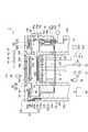
図1は、一つの例示的実施形態に係るプラズマ処理装置を概略的に示す図である。図2、図3、及び図4は、図1に示すプラズマ処理装置の一部拡大断面図である。図2には、一例のシャッター機構の弁体によって対応の開口が閉じられている状態が示されている。また、図3には、一例のシャッター機構の弁体が対応の開口を開いている状態が示されている。図1~図4に示すプラズマ処理装置1は、チャンバ10を備えている。チャンバ10は、その中に内部空間10sを提供している。内部空間10sは、減圧可能である。内部空間10sの中ではプラズマが形成される。FIG. 1 is a diagram schematically showing a plasma processing apparatus according to one exemplary embodiment. 2, 3, and 4 are partially enlarged cross-sectional views of the plasma processing apparatus shown in FIG. FIG. 2 shows a state where a corresponding opening is closed by a valve body of an example shutter mechanism. FIG. 3 shows a state where the valve body of the example shutter mechanism has a corresponding opening. The plasma processing apparatus 1 shown in FIGS. 1 to 4 includes a
チャンバ10は、チャンバ本体12及び天部14を含んでいる。チャンバ本体12は、チャンバ10の側壁及び底部を構成している。チャンバ本体12は、略円筒形状を有している。チャンバ本体12の中心軸線は、鉛直方向に延びる軸線AXに略一致している。チャンバ本体12は、電気的に接地されている。チャンバ本体12は、例えばアルミニウムから形成されている。チャンバ本体12の表面には、耐腐食性の膜が形成されている。耐腐食性の膜は、例えば、酸化アルミニウム又は酸化イットリウムといった材料から形成されている。The
チャンバ10の側壁には、開口12pが形成されている。開口12pは、チャンバ本体12によって提供されている。開口12pは、ゲートバルブ12gによって開閉可能である。基板Wは、内部空間10sとチャンバ10の外部との間で搬送されるときに、開口12pを通過する。開口 An opening 12p is formed in the side wall of the
一実施形態において、チャンバ本体12は、第1部材12a及び第2部材12bを含んでいる。第1部材12aは、略円筒形状を有している。第1部材12aは、チャンバ10の底部及び側壁の一部を構成している。第2部材12bは、略円筒形状を有している。第2部材12bは、第1部材12a上に設けられている。第2部材12bは、チャンバ10の側壁の別の一部を構成している。第2部材12bは、開口12pを提供している。In one embodiment, the
内部空間10sの中には、支持台16が設けられている。支持台16は、その上に載置される基板Wを支持するように構成されている。支持台16の下方には、底板17が設けられている。底板17は、チャンバ10の底部、例えば第1部材12aによって支持されている。底板17からは、支持体18が上方に延在している。支持体18は、略円筒形状を有している。支持体18は、例えば石英といった絶縁体から形成されている。支持台16は、支持体18上に搭載されており、支持体18によって支持されている。支持 A
支持台16は、下部電極20及び静電チャック22を含んでいる。支持台16は、電極プレート24を更に含んでいてもよい。電極プレート24は、略円盤形状を有している。電極プレート24の中心軸線は、軸線AXに略一致している。電極プレート24は、アルミニウムといった導体から形成されている。The
下部電極20は、電極プレート24上に設けられている。下部電極20は、電極プレート24に電気的に接続されている。下部電極20は、略円盤形状を有している。下部電極20の中心軸線は、軸線AXに略一致している。下部電極20は、アルミニウムといった導体から形成されている。下部電極20の中には、流路20fが形成されている。流路20fは、例えば渦巻き状に延在している。流路20fには、チラーユニット26から冷媒が供給される。チラーユニット26は、チャンバ10の外部に設けられている。チラーユニット26は、例えば液状の冷媒を流路20fに供給する。流路20fに供給された冷媒は、チラーユニット26に戻される。The
静電チャック22は、下部電極20上に設けられている。静電チャック22は、本体と電極22aを含んでいる。静電チャック22の本体は、略円盤形状を有している。静電チャック22の中心軸線は、軸線AXと略一致している。静電チャック22の本体は、セラミックから形成されている。電極22aは、導体から形成された膜である。電極22aは、静電チャック22の本体内に設けられている。電極22aには、スイッチ22sを介して直流電源22dが接続されている。静電チャック22に基板Wを保持させる場合には、直流電源22dからの電圧が電極22aに印加される。電極22aに電圧が印加されると静電チャック22と基板Wとの間で静電引力が発生する。発生した静電引力により、基板Wは静電チャック22に引き付けられ、静電チャック22によって保持される。プラズマ処理装置1は、静電チャック22と基板Wの裏面との間に、伝熱ガス(例えば、ヘリウムガス)を供給するガスラインを提供していてもよい。The
静電チャック22の周縁部上には、フォーカスリングFRが、基板Wを囲むように配置される。フォーカスリングFRは、基板Wに対するプラズマ処理の面内均一性を改善するために利用される。フォーカスリングFRは、例えばシリコン、石英、又は炭化ケイ素から形成されている。フォーカスリングFRと下部電極20との間には、リング27が設けられている。リング27は、絶縁体から形成されている。フ ォ ー カ ス A focus ring FR is arranged on the peripheral portion of the
プラズマ処理装置1は、筒状部28及び筒状部29を更に備えていてもよい。筒状部28は、支持台16及び支持体18の外周に沿って延在している。筒状部28は、筒状部29上に設けられている。筒状部28は、耐腐食性を有する絶縁体から形成されている。筒状部28は、例えば石英から形成されている。筒状部29は、支持体18の外周に沿って延在している。筒状部29は、耐腐食性を有する絶縁体から形成されている。筒状部29は、例えば石英から形成されている。The plasma processing apparatus 1 may further include a
天部14は、チャンバ10の上端開口を閉じるように設けられている。天部14は、上部電極30を含んでいる。天部14は、部材32(上部部品)及び部材34を更に含み得る。部材32は、略環状の板であり、アルミニウムといった金属から形成されている。部材32は、後述する部材58を介して、チャンバ10の側壁上に設けられている。即ち、部材32は、部材58上に設けられている。部材34は、上部電極30と部材32との間に設けられている。部材34は、軸線AXに対して周方向に延在している。部材34は、石英といった絶縁体から形成されている。上部電極30は、部材32によって画成された開口内に部材34を介して配置されている。上部電極30は、部材34を介して部材32によって支持されている。なお、上部電極30と部材34との間には、Oリングといった封止部材35aが介在している。部材34と部材32との間には、Oリングといった封止部材35bが介在している。The
上部電極30は、天板36及び支持体38を含んでいる。天板36は、略円盤形状を有している。天板36は、内部空間10sに接している。天板36には、複数のガス吐出孔36hが形成されている。複数のガス吐出孔36hは、板厚方向(鉛直方向)に天板36を貫通している。天板36は、シリコン、酸化アルミニウム、又は石英から形成されている。或いは、天板36は、アルミニウムといった導体製の部材の表面上に耐腐食性の膜を形成することにより構成されていてもよい。耐腐食性の膜は、例えば、酸化アルミニウム又は酸化イットリウムといった材料から形成されている。The
支持体38は、天板36上に設けられている。支持体38は、天板36を着脱自在に支持している。支持体38は、例えばアルミニウムから形成されている。支持体38には、流路38fが形成されている。流路38fは、支持体38内で、例えば渦巻き状に延在している。流路38fには、チラーユニット40から冷媒が供給される。チラーユニット40は、チャンバ10の外部に設けられている。チラーユニット40は、液状の冷媒(例えば冷却水)を流路38fに供給する。流路38fに供給された冷媒は、チラーユニット40に戻される。このチラーユニット40は、例えば4L/min以上の流量で冷媒を流路38fに供給し得る。The
支持体38の内部には、ガス拡散室38dが形成されている。支持体38には、複数の孔38hが形成されている。複数の孔38hは、ガス拡散室38dから下方に延びて、複数のガス吐出孔36hにそれぞれ接続している。支持体38には、ポート38pが設けられている。ポート38pは、ガス拡散室38dに接続している。ポート38pには、ガスソース群41が、バルブ群42、流量制御器群43、及びバルブ群44を介して接続されている。ガ ス A
ガスソース群41は、複数のガスソースを含んでいる。バルブ群42及びバルブ群44の各々は、複数のバルブを含んでいる。流量制御器群43は、複数の流量制御器を含んでいる。複数の流量制御器の各々は、マスフローコントローラ又は圧力制御式の流量制御器である。ガスソース群41の複数のガスソースの各々は、バルブ群44の対応のバルブ、流量制御器群43の対応の流量制御器、及びバルブ群42の対応のバルブを介して、ポート38pに接続されている。プラズマ処理装置1では、ガスソース群41の複数のガスソースのうち選択された一以上のガスソースの各々からのガスが、ガス拡散室38dに供給される。ガス拡散室38dに供給されたガスは、複数のガス吐出孔36hから内部空間10sに供給される。The
プラズマ処理装置1は、第1の高周波電源51及び第2の高周波電源52を更に備えている。第1の高周波電源51は、プラズマ生成用の第1の高周波電力を発生する電源である。第1の高周波電力の周波数は、例えば27MHz以上である。第1の高周波電源51は、整合器53を介して下部電極20に電気的に接続されている。整合器53は、負荷側(下部電極20側)のインピーダンスを第1の高周波電源51の出力インピーダンスに整合させるためのマッチング回路を有している。なお、第1の高周波電源51は、下部電極20ではなく、整合器53を介して上部電極30に接続されていてもよい。The plasma processing apparatus 1 further includes a first high-
第2の高周波電源52は、基板Wにイオンを引き込むための第2の高周波電力を発生する電源である。第2の高周波電力の周波数は、例えば13.56MHz以下である。第2の高周波電源52は、整合器54を介して下部電極20に電気的に接続されている。整合器54は、負荷側(下部電極20側)のインピーダンスを第2の高周波電源52の出力インピーダンスに整合させるためのマッチング回路を有している。The second high-
プラズマ処理装置1は、部材58を更に備えている。部材58は、部分的に内部空間10sの中に設けられている。即ち、部材58の一部は、内部空間10sの中でプラズマに晒される。部材58は、内部空間10sからチャンバ10の外側に向けて延びてチャンバ10の外側の空間に対して露出されている。The plasma processing apparatus 1 further includes a
一実施形態では、部材58は、プラズマ処理による副生成物がチャンバ10の内壁面に堆積することを抑制するよう、チャンバ10の内壁面に沿って延在している。具体的には、部材58は、チャンバ本体12の内壁面又は第2部材12bの内壁面に沿って延在している。部材58は、略円筒形状を有している。部材58は、アルミニウムといった導体製の部材の表面上に耐腐食性の膜を形成することにより構成され得る。耐腐食性の膜は、例えば酸化アルミニウム又は酸化イットリウムといった材料から形成されている。In one embodiment, the
一実施形態において、部材58は、チャンバ本体12と天部14との間で挟持されている。例えば、部材58は、チャンバ本体12の第2部材12bと天部14の部材32との間で挟持されている。に お い て In one embodiment, the
一実施形態において、プラズマ処理装置1は、スペーサ59を更に備えていてもよい。スペーサ59は、板状をなしており、軸線AXの周りで周方向に延びている。スペーサ59は、部材58とチャンバ10との間に設けられている。スペーサ59は、例えば導体から形成されている。スペーサ59は、アルミニウムの熱伝導率よりも低い熱伝導率を有する材料から形成されていてもよい。スペーサ59は、例えばステンレスから形成されていてもよい。スペーサ59は、アルミニウムの熱伝導率よりも低い熱伝導率を有する材料であれば、ステンレス以外の材料から形成されていてもよい。なお、スペーサ59は、アルミニウムから形成されていてもよい。In one embodiment, the plasma processing apparatus 1 may further include a
一実施形態において、スペーサ59は、部材58と第2部材12bとの間に設けられている。一実施形態において、スペーサ59及び第2部材12bは、ねじ60aを用いて第1部材12aに固定されている。ねじ60aは、スペーサ59及び第2部材12bを貫通して第1部材12aのねじ穴に螺合している。部材58は、ねじ60bを用いてスペーサ59に固定されている。ねじ60bは、部材58を貫通してスペーサ59のねじ穴に螺合している。この実施形態によれば、例えばそのメンテナンスのために部材58がチャンバ10から取り外されても、スペーサ59及び第2部材12bは、ねじ60aによって第1部材12aに固定されたままである。したがって、スペーサ59及び第2部材12bの固定を維持したまま、部材58をチャンバ10から取り外すことが可能となる。に お い て In one embodiment, the
プラズマ処理装置1は、ヒータユニット62を更に備えている。ヒータユニット62は、本体62m及びヒータ62hを含んでいる。ヒータ62hは、部材58を加熱するように構成されている。ヒータ62hは、抵抗加熱素子であり得る。ヒータ62hは、本体62m内に設けられている。本体62mは、部材58に熱的に接している。一実施形態では、本体62mは、部材58に物理的に接している。本体62mは、アルミニウムといった導体から形成されている。ヒータ62hは、本体62mを介して部材58を加熱するように構成されている。The plasma processing apparatus 1 further includes a
一実施形態において、本体62mは、略略環状の板であり、上部電極30を囲むように周方向に延在している。一実施形態において、天部14は、部材56を更に含んでいる。部材56は、略環状の板である。部材56は、天板36の径方向外側の領域で周方向に延在している。径方向は、軸線AXに対して放射方向である。ヒータユニット62は、部材56と部材32との間、且つ、部材34と部材58との間に設けられている。に お い て In one embodiment, the
本体62mとその周囲の部材との間には、内部空間10sを含む減圧環境と大気圧環境とを分離するためにOリングといった封止部材が設けられている。具体的に、本体62mと部材32との間には、封止部材63aが設けられている。また、本体62mと部材58との間には、封止部材63bが設けられている。封 止 A sealing member such as an O-ring is provided between the
部材58と支持体18との間には、バッフル部材72が設けられている。一実施形態において、バッフル部材72は、略円筒形状を有している。バッフル部材72の上端は、鍔状に形成されている。バッフル部材72の下端は、略環形状に形成されており、径方向内側に延びている。バッフル部材72の上端の外縁は、部材58の下端に結合されている。バッフル部材72の下端の内縁は、筒状部29と底板17との間に挟持されている。バッフル部材72は、アルミニウムといった導体製の板から形成されている。バッフル部材72の表面には、耐腐食性の膜が形成されている。耐腐食性の膜は、例えば、酸化アルミニウム又は酸化イットリウムといった材料から形成されている。バッフル部材72には、複数の貫通孔が形成されている。A
内部空間10sは、バッフル部材72の下方で延在する排気領域を含んでいる。排気領域には、排気装置74が接続されている。排気装置74は、自動圧力制御弁といった圧力調整器及びターボ分子ポンプといった減圧ポンプを含んでいる。The
部材58には、開口58pが形成されている。開口58pは、開口12pと対面するように部材58に形成されている。基板Wは、内部空間10sとチャンバ10の外部との間で搬送されるときに、開口12p及び開口58pを通過する。An
プラズマ処理装置1は、シャッター機構76を更に備えていてもよい。シャッター機構76は、開口58pを開閉するように構成されている。シャッター機構76は、弁体76v及び軸体76sを有している。シャッター機構76は、筒体76a、封止部76b、壁部76w、及び駆動部76dを更に有し得る。The plasma processing apparatus 1 may further include a
弁体76vは、開口58p内に配置されている状態では開口58pを閉じる。弁体76vは軸体76sによって支持されている。即ち、軸体76sは、弁体76vに連結している。軸体76sは、弁体76vから下方に延在している。軸体76sは、主部76m及びフランジ76fを含んでいる。主部76mは、略筒状に形成されている。即ち、軸体76sは、その内部に空洞76cを提供している。フランジ76fは、主部76mの上端の上に設けられている。弁体76vは、フランジ76f上に設けられている。軸体76sの空洞76cは、フランジ76fの中にも形成されている。フランジ76fの中には、ヒータ76hが設けられている。ヒータ76hは、例えば抵抗加熱素子である。ヒータ76hは、フランジ76fを介して弁体76vを加熱するように構成されている。The
筒体76aは、筒形状をなしている。筒体76aは、直接的に又は間接的にチャンバ本体12に固定されている。軸体76sの主部76mは、筒体76aの中を通って上下に移動可能になっている。駆動部76dは、軸体76sの主部76mを上下に移動させるための動力を発生する。駆動部76dは、例えばモータを含む。The
封止部76bは、筒体76aの中に設けられている。封止部76bは、筒体76aと軸体76sの主部76mとの間の間隙を閉じており、内部空間10sの気密を確保している。封止部76bは、限定されるものではないが、Oリング又は磁性流体シールであり得る。壁部76wは、筒体76aとチャンバ本体12との間で延在している。壁部76wは、筒体76aとチャンバ本体12との間の間隙を閉じており、内部空間10sの気密を確保している。The sealing
プラズマ処理装置1は、供給器78を更に備えていてもよい。供給器78は、空洞76cに冷媒を供給するように構成されている。冷媒は、例えばエア、冷却空気、又は不活性ガスである。シャッター機構76の軸体76sに冷媒が供給されることにより、弁体76vが間接的に冷却される。したがって、弁体76vに直接的に冷媒を供給することなく、間接的に弁体76vを冷却することが可能である。The plasma processing apparatus 1 may further include a
一実施形態においてプラズマ処理装置1は、制御部80を更に備え得る。制御部80は、プラズマ処理装置1の各部を制御するように構成されている。制御部80は、例えば、コンピュータ装置である。制御部80は、プロセッサ、記憶部、キーボードといった入力装置、表示装置、及び信号の入出力インタフェイスを有する。記憶部には、制御プログラム及びレシピデータが記憶されている。プロセッサは、制御プログラムを実行し、レシピデータに従ってプラズマ処理装置1の各部に入出力インタフェイスを介して制御信号を送出する。に お い て In one embodiment, the plasma processing apparatus 1 may further include a
以上説明したように、プラズマ処理装置1では、部材58は、減圧された内部空間10s内にのみ配置されるのではなく、内部空間10sからチャンバ10の外側に向けて延びてチャンバ10の外側の大気に接するように構成されている。したがって、部材58は、十分に冷却され得る。また、部材58は、ヒータ62hによって加熱される。したがって、部材58の温度を制御することが可能である。As described above, in the plasma processing apparatus 1, the
一実施形態においては、上述したように、スペーサ59がチャンバ10と部材58との間に設けられてもよい。スペーサ59は、チャンバ10と部材58との間の熱抵抗を増加させる。したがって、内部空間10sの中でプラズマが生成されている場合に、プラズマからの熱によって部材58の温度が上昇しても、チャンバ10の温度上昇が抑制され得る。In one embodiment, the
一実施形態において、スペーサ59は、アルミニウムの熱伝導率よりも低い熱伝導率を有する材料(例えばステンレス)から形成されていてもよい。かかるスペーサ59の材料は、高い熱抵抗を有する。したがって、この実施形態によれば、内部空間10sの中でプラズマが生成されている場合に、チャンバ10の温度上昇が更に抑制され得る。In one embodiment, the
以下、図5を参照し、別の例示的実施形態について説明する。図5は、別の例示的実施形態に係るプラズマ処理装置を概略的に示す図である。図5に示すプラズマ処理装置1Bは、プラズマ処理装置1は、部材32ではなく部材32B(上部部品)を備えている。プラズマ処理装置1Bの他の構成は、プラズマ処理装置1の構成と同様である。Hereinafter, another exemplary embodiment will be described with reference to FIG. FIG. 5 is a diagram schematically illustrating a plasma processing apparatus according to another exemplary embodiment. The
部材32Bは、部材32と同様の部材であるが、その中に流路32fが形成されている点で部材32と異なっている。流路32fは、一例では、軸線AXの周りで周方向に延在している。流路32fには、チラーユニット82から冷媒が供給される。チラーユニット82は、チャンバ10の外部に設けられている。チラーユニット82は、例えば液状の冷媒を流路32fに供給する。流路32fに供給された冷媒は、チラーユニット82に戻される。The
プラズマ処理装置1Bによれば、部材32Bに冷媒を供給することにより、部材58を冷却することが可能である。その結果、部材58を取り扱う作業に安全な比較的低い温度に部材58の温度を設定することが可能となる。なお、部材58にはねじ60bがその中を通る貫通孔が形成されている。したがって、部材58内には冷媒用の流路のために残された領域が少ないか、残されていない。一方、部材32Bは、その中に流路32f用の領域を確保可能である。また、部材32Bは、部材58上で延在して、部材58に熱的に接触しているので、部材58と部材32Bとの間での熱交換及び部材32Bと冷媒との間の熱交換により、部材58を冷却することが可能である。According to the
以上、種々の例示的実施形態について説明してきたが、上述した例示的実施形態に限定されることなく、様々な省略、置換、及び変更がなされてもよい。また、異なる実施形態における要素を組み合わせて他の実施形態を形成することが可能である。Although various exemplary embodiments have been described above, various omissions, substitutions, and changes may be made without being limited to the exemplary embodiments described above. Also, other embodiments can be formed by combining elements in different embodiments.
例えば、プラズマ処理装置1は容量結合型のプラズマ処理装置であるが、別の実施形態においてプラズマ処理装置は、他のタイプのプラズマ処理装置であってもよい。他のタイプのプラズマ処理装置としては、誘導結合型のプラズマ処理装置又はマイクロ波といった表面波を用いてプラズマを生成するプラズマ処理装置が例示される。For example, the plasma processing apparatus 1 is a capacitively-coupled plasma processing apparatus, but in another embodiment, the plasma processing apparatus may be another type of plasma processing apparatus. Examples of another type of plasma processing apparatus include an inductively coupled plasma processing apparatus and a plasma processing apparatus that generates plasma using a surface wave such as a microwave.
以上の説明から、本開示の種々の実施形態は、説明の目的で本明細書で説明されており、本開示の範囲及び主旨から逸脱することなく種々の変更をなし得ることが、理解されるであろう。したがって、本明細書に開示した種々の実施形態は限定することを意図しておらず、真の範囲と主旨は、添付の特許請求の範囲によって示される。From the above description, it is understood that various embodiments of the present disclosure have been described herein for purposes of explanation, and that various changes may be made without departing from the scope and spirit of the present disclosure. Will. Accordingly, the various embodiments disclosed herein are not intended to be limiting, with the true scope and spirit being indicated by the appended claims.
1…プラズマ処理装置、10…チャンバ、10s…内部空間、58…部材、62h…ヒータ。# 1: Plasma processing apparatus, 10: chamber, 10s: internal space, 58: member, 62h: heater.
Claims (8)
Translated fromJapaneseチャンバと、
前記チャンバの内部空間の中に部分的に配置された部材と、
前記部材を加熱するように構成されたヒータと、
を備え、
前記部材は、前記内部空間から前記チャンバの外側に向けて延びて前記チャンバの外側の空間に対して露出されている、
プラズマ処理装置。A plasma processing apparatus for performing plasma processing,
A chamber;
A member partially disposed within the interior space of the chamber;
A heater configured to heat the member;
With
The member extends from the internal space toward the outside of the chamber and is exposed to a space outside the chamber.
Plasma processing equipment.
前記ヒータユニットの前記本体は、前記部材に熱的に接するように設けられている、
請求項1~6の何れか一項に記載のプラズマ処理装置。Further comprising a main body and a heater unit including the heater provided in the main body,
The main body of the heater unit is provided so as to be in thermal contact with the member,
The plasma processing apparatus according to any one of claims 1 to 6.
前記上部部品には、そこに冷媒が供給される流路が形成されている、
請求項1~7の何れか一項に記載のプラズマ処理装置。An upper part provided on the member and in thermal contact with the member,
In the upper part, a flow path to which a coolant is supplied is formed,
The plasma processing apparatus according to any one of claims 1 to 7.
Priority Applications (3)
| Application Number | Priority Date | Filing Date | Title |
|---|---|---|---|
| CN201980054831.8ACN112585729B (en) | 2018-09-06 | 2019-08-23 | Plasma treatment equipment |
| US17/272,771US11869750B2 (en) | 2018-09-06 | 2019-08-23 | Plasma processing apparatus |
| KR1020217008955AKR102843560B1 (en) | 2018-09-06 | 2019-08-23 | plasma treatment device |
Applications Claiming Priority (4)
| Application Number | Priority Date | Filing Date | Title |
|---|---|---|---|
| JP2018166972 | 2018-09-06 | ||
| JP2018-166972 | 2018-09-06 | ||
| JP2019105393AJP7240958B2 (en) | 2018-09-06 | 2019-06-05 | Plasma processing equipment |
| JP2019-105393 | 2019-06-05 |
Publications (1)
| Publication Number | Publication Date |
|---|---|
| WO2020050071A1true WO2020050071A1 (en) | 2020-03-12 |
Family
ID=69722682
Family Applications (1)
| Application Number | Title | Priority Date | Filing Date |
|---|---|---|---|
| PCT/JP2019/033142CeasedWO2020050071A1 (en) | 2018-09-06 | 2019-08-23 | Plasma processing device |
Country Status (1)
| Country | Link |
|---|---|
| WO (1) | WO2020050071A1 (en) |
Cited By (1)
| Publication number | Priority date | Publication date | Assignee | Title |
|---|---|---|---|---|
| CN114231943A (en)* | 2021-12-13 | 2022-03-25 | 深圳优普莱等离子体技术有限公司 | Two-stage lifting system and equipment for chemical vapor deposition |
Citations (4)
| Publication number | Priority date | Publication date | Assignee | Title |
|---|---|---|---|---|
| JPH09162170A (en)* | 1995-12-07 | 1997-06-20 | Matsushita Electric Ind Co Ltd | Plasma processing method and apparatus |
| JP2008505489A (en)* | 2004-06-30 | 2008-02-21 | ラム リサーチ コーポレーション | Apparatus for optimized plasma chamber top member |
| JP2010507231A (en)* | 2006-10-16 | 2010-03-04 | ラム リサーチ コーポレーション | Upper electrode backing member with the function of reducing particles |
| JP2014130924A (en)* | 2012-12-28 | 2014-07-10 | Tokyo Electron Ltd | Plasma processing container and plasma processing apparatus |
- 2019
- 2019-08-23WOPCT/JP2019/033142patent/WO2020050071A1/ennot_activeCeased
Patent Citations (4)
| Publication number | Priority date | Publication date | Assignee | Title |
|---|---|---|---|---|
| JPH09162170A (en)* | 1995-12-07 | 1997-06-20 | Matsushita Electric Ind Co Ltd | Plasma processing method and apparatus |
| JP2008505489A (en)* | 2004-06-30 | 2008-02-21 | ラム リサーチ コーポレーション | Apparatus for optimized plasma chamber top member |
| JP2010507231A (en)* | 2006-10-16 | 2010-03-04 | ラム リサーチ コーポレーション | Upper electrode backing member with the function of reducing particles |
| JP2014130924A (en)* | 2012-12-28 | 2014-07-10 | Tokyo Electron Ltd | Plasma processing container and plasma processing apparatus |
Cited By (1)
| Publication number | Priority date | Publication date | Assignee | Title |
|---|---|---|---|---|
| CN114231943A (en)* | 2021-12-13 | 2022-03-25 | 深圳优普莱等离子体技术有限公司 | Two-stage lifting system and equipment for chemical vapor deposition |
Similar Documents
| Publication | Publication Date | Title |
|---|---|---|
| JP7066512B2 (en) | Plasma processing equipment | |
| US11743973B2 (en) | Placing table and plasma processing apparatus | |
| KR102383357B1 (en) | Mounting table and substrate processing apparatus | |
| TWI651798B (en) | Mounting table and plasma processing device | |
| US11967511B2 (en) | Plasma processing apparatus | |
| JP7340938B2 (en) | Mounting table and substrate processing equipment | |
| JP7240958B2 (en) | Plasma processing equipment | |
| JP2007250860A (en) | Plasma processor and electrode assembly therefor | |
| JP7333712B2 (en) | Electrostatic chuck, support table and plasma processing equipment | |
| WO2020050071A1 (en) | Plasma processing device | |
| KR102823386B1 (en) | Plasma processing apparatus | |
| JP7394556B2 (en) | Mounting table and substrate processing equipment | |
| KR102712692B1 (en) | Structure for substrate processing apparatus and substrate processing apparatus | |
| JP2021013011A (en) | Substrate processing apparatus | |
| KR20210004845A (en) | Substrate processing apparatus | |
| JP7394661B2 (en) | Substrate processing equipment | |
| US20210090864A1 (en) | Dielectric member, structure, and substrate processing apparatus | |
| JP2022150921A (en) | Plasma processing apparatus |
Legal Events
| Date | Code | Title | Description |
|---|---|---|---|
| 121 | Ep: the epo has been informed by wipo that ep was designated in this application | Ref document number:19857179 Country of ref document:EP Kind code of ref document:A1 | |
| NENP | Non-entry into the national phase | Ref country code:DE | |
| ENP | Entry into the national phase | Ref document number:20217008955 Country of ref document:KR Kind code of ref document:A | |
| 122 | Ep: pct application non-entry in european phase | Ref document number:19857179 Country of ref document:EP Kind code of ref document:A1 |