WO2020036109A1 - Medical image processing device, endoscope system, and operation method for medical image processing device - Google Patents
Medical image processing device, endoscope system, and operation method for medical image processing deviceDownload PDFInfo
- Publication number
- WO2020036109A1 WO2020036109A1PCT/JP2019/031133JP2019031133WWO2020036109A1WO 2020036109 A1WO2020036109 A1WO 2020036109A1JP 2019031133 WJP2019031133 WJP 2019031133WWO 2020036109 A1WO2020036109 A1WO 2020036109A1
- Authority
- WO
- WIPO (PCT)
- Prior art keywords
- attention area
- unit
- detection time
- medical image
- detected
- Prior art date
- Legal status (The legal status is an assumption and is not a legal conclusion. Google has not performed a legal analysis and makes no representation as to the accuracy of the status listed.)
- Ceased
Links
Images


Classifications
- A—HUMAN NECESSITIES
- A61—MEDICAL OR VETERINARY SCIENCE; HYGIENE
- A61B—DIAGNOSIS; SURGERY; IDENTIFICATION
- A61B1/00—Instruments for performing medical examinations of the interior of cavities or tubes of the body by visual or photographical inspection, e.g. endoscopes; Illuminating arrangements therefor
- A61B1/00002—Operational features of endoscopes
- A61B1/00004—Operational features of endoscopes characterised by electronic signal processing
- A61B1/00006—Operational features of endoscopes characterised by electronic signal processing of control signals
- A—HUMAN NECESSITIES
- A61—MEDICAL OR VETERINARY SCIENCE; HYGIENE
- A61B—DIAGNOSIS; SURGERY; IDENTIFICATION
- A61B1/00—Instruments for performing medical examinations of the interior of cavities or tubes of the body by visual or photographical inspection, e.g. endoscopes; Illuminating arrangements therefor
- A61B1/00002—Operational features of endoscopes
- A61B1/00004—Operational features of endoscopes characterised by electronic signal processing
- A61B1/00009—Operational features of endoscopes characterised by electronic signal processing of image signals during a use of endoscope
- A61B1/000094—Operational features of endoscopes characterised by electronic signal processing of image signals during a use of endoscope extracting biological structures
- A—HUMAN NECESSITIES
- A61—MEDICAL OR VETERINARY SCIENCE; HYGIENE
- A61B—DIAGNOSIS; SURGERY; IDENTIFICATION
- A61B1/00—Instruments for performing medical examinations of the interior of cavities or tubes of the body by visual or photographical inspection, e.g. endoscopes; Illuminating arrangements therefor
- A61B1/00002—Operational features of endoscopes
- A61B1/00043—Operational features of endoscopes provided with output arrangements
- A61B1/00045—Display arrangement
- A—HUMAN NECESSITIES
- A61—MEDICAL OR VETERINARY SCIENCE; HYGIENE
- A61B—DIAGNOSIS; SURGERY; IDENTIFICATION
- A61B1/00—Instruments for performing medical examinations of the interior of cavities or tubes of the body by visual or photographical inspection, e.g. endoscopes; Illuminating arrangements therefor
- A61B1/00163—Optical arrangements
- A61B1/00188—Optical arrangements with focusing or zooming features
- A—HUMAN NECESSITIES
- A61—MEDICAL OR VETERINARY SCIENCE; HYGIENE
- A61B—DIAGNOSIS; SURGERY; IDENTIFICATION
- A61B1/00—Instruments for performing medical examinations of the interior of cavities or tubes of the body by visual or photographical inspection, e.g. endoscopes; Illuminating arrangements therefor
- A61B1/04—Instruments for performing medical examinations of the interior of cavities or tubes of the body by visual or photographical inspection, e.g. endoscopes; Illuminating arrangements therefor combined with photographic or television appliances
- A61B1/045—Control thereof
- A—HUMAN NECESSITIES
- A61—MEDICAL OR VETERINARY SCIENCE; HYGIENE
- A61B—DIAGNOSIS; SURGERY; IDENTIFICATION
- A61B1/00—Instruments for performing medical examinations of the interior of cavities or tubes of the body by visual or photographical inspection, e.g. endoscopes; Illuminating arrangements therefor
- A61B1/06—Instruments for performing medical examinations of the interior of cavities or tubes of the body by visual or photographical inspection, e.g. endoscopes; Illuminating arrangements therefor with illuminating arrangements
- A61B1/0638—Instruments for performing medical examinations of the interior of cavities or tubes of the body by visual or photographical inspection, e.g. endoscopes; Illuminating arrangements therefor with illuminating arrangements providing two or more wavelengths
- A—HUMAN NECESSITIES
- A61—MEDICAL OR VETERINARY SCIENCE; HYGIENE
- A61B—DIAGNOSIS; SURGERY; IDENTIFICATION
- A61B1/00—Instruments for performing medical examinations of the interior of cavities or tubes of the body by visual or photographical inspection, e.g. endoscopes; Illuminating arrangements therefor
- A61B1/06—Instruments for performing medical examinations of the interior of cavities or tubes of the body by visual or photographical inspection, e.g. endoscopes; Illuminating arrangements therefor with illuminating arrangements
- A61B1/0655—Control therefor
- A—HUMAN NECESSITIES
- A61—MEDICAL OR VETERINARY SCIENCE; HYGIENE
- A61B—DIAGNOSIS; SURGERY; IDENTIFICATION
- A61B1/00—Instruments for performing medical examinations of the interior of cavities or tubes of the body by visual or photographical inspection, e.g. endoscopes; Illuminating arrangements therefor
- A61B1/06—Instruments for performing medical examinations of the interior of cavities or tubes of the body by visual or photographical inspection, e.g. endoscopes; Illuminating arrangements therefor with illuminating arrangements
- A61B1/0661—Endoscope light sources
- A61B1/0669—Endoscope light sources at proximal end of an endoscope
- A—HUMAN NECESSITIES
- A61—MEDICAL OR VETERINARY SCIENCE; HYGIENE
- A61B—DIAGNOSIS; SURGERY; IDENTIFICATION
- A61B1/00—Instruments for performing medical examinations of the interior of cavities or tubes of the body by visual or photographical inspection, e.g. endoscopes; Illuminating arrangements therefor
- A61B1/06—Instruments for performing medical examinations of the interior of cavities or tubes of the body by visual or photographical inspection, e.g. endoscopes; Illuminating arrangements therefor with illuminating arrangements
- A61B1/07—Instruments for performing medical examinations of the interior of cavities or tubes of the body by visual or photographical inspection, e.g. endoscopes; Illuminating arrangements therefor with illuminating arrangements using light-conductive means, e.g. optical fibres
- G—PHYSICS
- G02—OPTICS
- G02B—OPTICAL ELEMENTS, SYSTEMS OR APPARATUS
- G02B23/00—Telescopes, e.g. binoculars; Periscopes; Instruments for viewing the inside of hollow bodies; Viewfinders; Optical aiming or sighting devices
- G02B23/24—Instruments or systems for viewing the inside of hollow bodies, e.g. fibrescopes
Definitions
- the present inventionrelates to a medical image processing device and an endoscope system for detecting a region of interest such as a lesion, and an operation method of the medical image processing device.
- medical diagnosissuch as endoscopic images, X-ray images, CT (Computed Tomography) images, and MR (Magnetic Resonanse) images are used to perform image diagnosis such as diagnosis of disease states and follow-up observations of patients. ing. Based on such image diagnosis, doctors and the like make decisions on treatment policies and the like.
- a medical imageis analyzed to automatically detect a region of interest to be observed carefully, such as a lesion or a tumor in an organ.
- machine learningsuch as deep learning
- Patent Document 1describes a medical image processing apparatus that performs image processing based on a detection result when a region of interest such as a lesion is detected from a medical image.
- a region of interestsuch as a lesion
- Patent Document 1describes a medical image processing apparatus that performs image processing based on a detection result when a region of interest such as a lesion is detected from a medical image.
- an elapsed time for changing the display modeis set, and until the set elapsed time, alert information for the attention area is displayed.
- a display image added or superimposedis generated and displayed on the display unit.
- the present inventionprovides a medical image processing apparatus, an endoscope system, and a method of operating a medical image processing apparatus that can prevent a display based on detection of a region of interest from obstructing observation of a medical image. Aim.
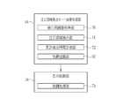
- the medical image processing device of the present inventionincludes a medical image acquisition unit, a region of interest detection unit, a cumulative detection time measurement unit, and a display control unit.
- the medical image acquisition unitacquires a medical image by imaging an observation target with an imaging unit.
- the attention area detection unitdetects an attention area in the observation target with respect to the medical image acquired by the medical image acquisition unit.
- the total detection time measuring unitmeasures the total detection time during which the attention area is detected.
- the display control unitis a display control unit that highlights the attention area detected by the attention area detection unit on the medical image, and changes the highlight display according to the total detection time.
- the display control unitmaximizes the emphasis amount of the emphasis display at the start of the detection of the attention area, and gradually decreases the emphasis amount as the total detection time increases.
- the cumulative detection time measuring unitmeasures the cumulative detection time for each detected region of interest when the region of interest is detected by the region of interest detection unit during imaging by the imaging unit. It is preferable to change the highlighting in accordance with the total detection time.
- An attention area storage unitthat stores the total detection time of each attention area detected in the past by the attention area detection unit in association with feature amount information representing a feature amount of each attention area, and an attention area stored in the attention area storage unit From the similarity between any one of the feature amounts of interest and the feature amount of the attention region newly detected by the attention region detection unit, the same attention region determination unit that determines whether it is the same as any of the attention regions detected in the past
- the cumulative detection time measurement unitis determined to be the same when it is determined during the imaging by the imaging unit that any of the attention regions detected in the past by the same attention region determination unit is the same.
- the total detection time for the past attention areais taken over and measured, and if the same attention area determination unit determines that it is not the same as any of the attention areas detected in the past, the attention area detection unit It is preferred to start measurement is reset the cumulative detection time with respect to the detected region of interest.
- the attention area storage unitstores the latest detection time of each attention area detected in the past in association with the total detection time and the feature amount information, and the total detection time measurement unit newly detects during the imaging by the imaging unit. This is a case where the same attention area is determined by the same attention area determination unit to be the same as any of the attention areas detected in the past, and the most recent detection time and the detection time when the attention area is newly detected.
- the time intervalis larger than the predetermined value, it is preferable that the measurement is started after resetting the total detection time for the attention area newly detected by the attention area detection unit.
- a treatment recognition unit that recognizes that a specific treatment has been performed in the observation targethas been provided, and the cumulative detection time measurement unit has recognized that the specific treatment has been performed by the treatment recognition unit during imaging by the imaging unit. In this case, it is preferable to start the measurement after resetting the total detection time for the attention area newly detected by the attention area detection unit.
- the display control unitsuperimposes and displays a figure at the position of the attention area in the medical image as the highlight display. Further, it is preferable that the display control unit changes the color of the graphic displayed as the highlighted display according to the total detection time. Furthermore, it is preferable that the display control unit changes the transparency of the graphic to be superimposed on the attention area according to the total detection time.
- the display control unitchanges the shape of the graphic displayed as the highlighted display according to the total detection time. Further, it is preferable that the display control section displays a frame-shaped figure surrounding the attention area as highlighting, and changes the thickness of the frame of the figure according to the total detection time.
- the display control unitperforms highlighting by changing the color of the attention area, and returns to the color before the change of the attention area according to the total detection time.
- the endoscope system of the present inventionincludes a light source device, an endoscope, a medical image acquisition unit, a cumulative detection time measurement unit, a display control unit, and a display unit.
- the light source deviceemits illumination light for illuminating an observation target.
- the endoscopeincludes an imaging unit that captures an image of an observation target illuminated with illumination light.
- the medical image acquisition unitacquires a medical image obtained by imaging the observation target with the imaging unit.
- the attention area detection unitdetects an attention area in the observation target with respect to the medical image acquired by the medical image acquisition unit.
- the total detection time measuring unitmeasures the total detection time during which the attention area is detected.
- the display control unitis a display control unit that highlights the attention area detected by the attention area detection unit on the medical image, and changes the highlight display according to the total detection time.
- the display unitdisplays the medical image and the highlighted display.
- An operation method of the medical image processing apparatusincludes a step of acquiring a medical image by capturing an observation target with an imaging unit, and a medical image acquired by the medical image acquiring unit. Detecting the region of interest in the observation target with respect to the step of measuring the total detection time in which the region of interest is detected, and the display control unit Highlighting the attention area detected by the detection unit and changing the highlighting according to the total detection time.
- the present inventionit is possible to prevent the display based on the detection of the attention area from obstructing the observation of the medical image.
- FIG. 4is a block diagram illustrating functions of an attention area detection mode image processing unit and a display control unit. It is an example of a display screen when a display control part highlights an attention area, and is an explanatory view showing a change of the display screen in chronological order.
- FIG. 13is an explanatory diagram illustrating a relationship between a total detection time and a highlighted display when the display control unit according to the second embodiment highlights a plurality of attention areas.
- 10is an explanatory diagram corresponding to the display screen shown in FIG. 9 and showing changes in the display screen in chronological order.
- FIG. 14is a block diagram illustrating functions of an attention area detection mode image processing unit and a display control unit according to a third embodiment. It is explanatory drawing which shows the relationship between the total detection time and highlighting in the case where the same attention area
- FIG. 18is a block diagram illustrating functions of an attention area detection mode image processing unit and a display control unit in a fifth embodiment. It is explanatory drawing which shows the relationship between the total detection time in case a treatment recognition part performs a treatment recognition in 5th Embodiment, and highlighting.
- FIG. 11is an explanatory diagram illustrating a first modification in the case where a region of interest is highlighted.
- FIG. 14is an explanatory diagram showing a second modification in the case where the attention area is highlighted.
- the endoscope system 10includes an endoscope 12, a light source device 14, a processor device 16, a monitor 18 (display unit), and a console 19.
- the endoscope 12is optically connected to the light source device 14 and is electrically connected to the processor device 16.
- the endoscope 12has an insertion portion 12a to be inserted into a subject, an operation portion 12b provided at a base end portion of the insertion portion 12a, and a bending portion 12c and a tip portion 12d provided at a distal end side of the insertion portion 12a. are doing.
- the angle knob 13a of the operation section 12bBy operating the angle knob 13a of the operation section 12b, the bending section 12c performs a bending operation. By this bending operation, the tip 12d is directed in a desired direction.
- the distal end portion 12dhas an illumination window, an observation window, an air / water nozzle, and a forceps outlet (all not shown) on the distal end surface.
- the illumination windowis for irradiating illumination light to an observation site.
- the observation windowis for taking in light from the observation site.
- the air supply / water supply nozzleis for cleaning the illumination window and the observation window.
- the forceps outletis for performing various treatments using forceps and a treatment tool such as an electric scalpel.
- the operation unit 12bincludes, in addition to the angle knob 13a, a still image acquisition unit 13b used for a still image acquisition operation, a mode switching unit 13c used for an observation mode switching operation, and a zoom operation unit 13d used for a zoom magnification change operation. , An air supply / water supply operation unit 13e.
- the still image acquisition unit 13bcan perform a freeze operation of displaying a still image to be observed on the monitor 18 and a release operation of saving a still image in a storage.
- the air-supply / water-supply operation unit 13eis capable of performing an ejection operation of ejecting gas / liquid from the air-supply / water-supply nozzle of the tip 12d to wash the illumination window and the observation window.
- the endoscope system 10has a normal mode, a special mode, and an attention area detection mode as observation modes.
- the observation modeis the normal mode
- the light of a plurality of colorsis combined with the light amount ratio Lc for the normal mode to emit normal light.
- the observation modeis the special mode
- special lightis generated by combining light of a plurality of colors at the light amount ratio Ls for the special mode.
- the illumination light for the attention area detection modeis emitted.
- the normal lightis emitted as the illumination light for the attention area detection mode, but a special light may be emitted.
- the processor device 16is electrically connected to the monitor 18 and the console 19.
- the monitor 18outputs and displays an image of the observation target, information accompanying the image, and the like.
- the console 19functions as a user interface for receiving an input operation such as designation of a region of interest (ROI: ⁇ Region ⁇ Of ⁇ Interest) and function setting.
- ROIregion of interest
- the light source device 14includes a light source unit 20 that emits illumination light used for illumination of an observation target, and a light source control unit 22 that controls the light source unit 20.
- the light source unit 20is a semiconductor light source such as an LED (Light Emitting Diode) of a plurality of colors.
- the light source control unit 22controls the amount of emitted illumination light by turning on / off an LED or the like and adjusting a drive current or a drive voltage of the LED or the like.
- the light source control unit 22controls the wavelength band of the illumination light by changing an optical filter or the like.
- the light source unit 20includes a V-LED (Violet Light Emitting Diode) 20a, a B-LED (Blue Light Emitting Diode) 20b, a G-LED (Green Light Emitting Diode) 20c, and an R-LED (Red). It has four color LEDs (Light Emitting Diode) 20d and a wavelength cut filter 23. As shown in FIG. 3, the V-LED 20a emits violet light V in a wavelength band of 380 nm to 420 nm.
- the B-LED 20bemits blue light B having a wavelength band of 420 nm to 500 nm.
- the blue light B emitted from the B-LED 23bat least a wavelength longer than 450 nm of the peak wavelength is cut by the wavelength cut filter 23.
- the blue light Bx transmitted through the wavelength cut filter 23has a wavelength range of 420 to 460 nm.
- the light in the wavelength range longer than 460 nmis cut off because the light in the wavelength range longer than 460 nm lowers the blood vessel contrast of the blood vessel to be observed. Because there is.
- the wavelength cut filter 23may reduce light in a wavelength range longer than 460 nm instead of cutting light in a wavelength range longer than 460 nm.
- the G-LED 20cemits green light G whose wavelength band extends from 480 nm to 600 nm.
- the R-LED 20demits red light R having a wavelength band ranging from 600 nm to 650 nm.
- the light emitted from each of the LEDs 20a to 20dmay have the same center wavelength and the same peak wavelength, or may have different center wavelengths and peak wavelengths.
- the light source control unit 22adjusts the light emission timing, the light emission period, the light amount, and the spectrum of the illumination light by independently controlling the lighting and extinguishing of each of the LEDs 20a to 20d and the light emission amount at the time of lighting.
- the control of turning on and off the light in the light source control unit 22differs for each observation mode.
- the reference brightnesscan be set by the brightness setting unit of the light source device 14, the console 19, or the like.
- the light source control unit 22turns on all of the V-LED 20a, the B-LED 20b, the G-LED 20c, and the R-LED 20d.
- the light intensity ratio Lc among the violet light V, the blue light B, the green light G, and the red light Ris such that the peak of the light intensity of the blue light Bx is the violet light V, the green light G , And the red light R are set to be larger than the peak of the light intensity.
- the multi-color light for the normal mode or the attention area detection modeincluding the violet light V, the blue light Bx, the green light G, and the red light R is normally emitted from the light source device 14.
- Lightis emitted as light.
- the normal lighthas a certain intensity or more from the blue band to the red band, and is almost white.
- the light source control unit 22turns on all of the V-LED 20a, the B-LED 20b, the G-LED 20c, and the R-LED 20d.
- the light intensity ratio Ls among the violet light V, the blue light B, the green light G, and the red light Ris such that the peak of the light intensity of the violet light V is blue light Bx, green light G , And the red light R are set to be larger than the peak of the light intensity. Further, the peaks of the light intensity of the green light G and the red light R are set to be smaller than the peaks of the light intensity of the violet light V and the blue light Bx.
- the light source device 14emits the special mode polychromatic light including the violet light V, the blue light Bx, the green light G, and the red light R as the special light.
- the special lightis bluish light because the ratio of the purple light V is large.
- the special lightdoes not need to include all four colors of light, as long as it includes light from at least one of the four colors of LEDs 20a to 20d.
- the special lightpreferably has a main wavelength range of 450 nm or less, for example, a peak wavelength or a center wavelength.
- the illumination light emitted by the light source unit 20enters the light guide 24 inserted into the insertion unit 12a via an optical path coupling unit (not shown) formed by a mirror, a lens, and the like.
- the light guide 24is built in the endoscope 12 and the universal cord, and transmits the illumination light to the distal end 12 d of the endoscope 12.
- the universal cordis a cord that connects the endoscope 12, the light source device 14, and the processor device 16. Note that a multi-mode fiber can be used as the light guide 24.
- a thin fiber cable having a core diameter of 105 ⁇ m, a cladding diameter of 125 ⁇ m, and a diameter of 0.3 mm to 0.5 mm including a protective layer serving as an outer covercan be used for the light guide 24.
- An illumination optical system 30a and an imaging optical system 30bare provided at the distal end 12d of the endoscope 12.
- the illumination optical system 30ahas an illumination lens 32. Through this illumination lens 32, the observation target is illuminated by the illumination light that has propagated through the light guide 24.
- the imaging optical system 30bincludes an objective lens 34, an enlargement optical system 36, and an imaging sensor 38 (corresponding to the “imaging unit” of the present invention).
- Various lightssuch as reflected light, scattered light, and fluorescent light from the observation target enter the image sensor 38 via the objective lens 34 and the magnifying optical system 36. As a result, an image of the observation target is formed on the image sensor 38.
- the enlargement optical system 36includes a zoom lens 36a for enlarging an observation target, and a lens driving unit 36b for moving the zoom lens 36a in the optical axis direction CL.
- the zoom lens 36aenlarges or reduces the observation object formed on the image sensor 38 by freely moving between the telephoto end and the wide end in accordance with zoom control by the lens driving unit 36b.
- the imaging sensor 38is a color imaging sensor that captures an image of the observation target irradiated with the illumination light.
- Each pixel of the image sensor 38is provided with one of an R (red) color filter, a G (green) color filter, and a B (blue) color filter.
- the image sensor 38receives violet to blue light at a B pixel provided with a B color filter, receives green light at a G pixel provided with a G color filter, and has an R color filter.
- the red lightis received by the existing R pixel.
- the image signal of each color of RGBis output from the pixel of each color.
- the image sensor 38transmits the output image signal to the CDS circuit 40.
- the image sensor 38In the normal mode or the attention area detection mode, the image sensor 38 outputs a Bc image signal from a B pixel, outputs a Gc image signal from a G pixel, and outputs a Rc image by capturing an image of an observation target illuminated with normal light. An Rc image signal is output from the pixel.
- the image sensor 38In the special mode, the image sensor 38 outputs a Bs image signal from the B pixel, outputs a Gs image signal from the G pixel, and outputs Rs from the R pixel by imaging the observation target illuminated with the special light. Outputs an image signal.
- a CCD (Charge Coupled Device) imaging sensor, a CMOS (Complementary Metal-Oxide Semiconductor) imaging sensor, or the likecan be used.
- a complementary color image sensor having complementary color filters of C (cyan), M (magenta), Y (yellow) and G (green)may be used. good.
- image signals of four colors of CMYGare output. For this reason, by converting the image signals of four colors of CMYG into the image signals of three colors of RGB by the complementary color-primary color conversion, it is possible to obtain the image signals of each color of RGB similar to the image sensor 38.
- a monochrome sensor having no color filtermay be used.
- the CDS circuit 40performs correlated double sampling (CDS) on the analog image signal received from the image sensor 38.
- the image signal that has passed through the CDS circuit 40is input to the AGC circuit 42.
- the AGC circuit 40performs automatic gain control (AGC: Automatic Gain Control) on the input image signal.
- An A / D (Analog to Digital) conversion circuit 44converts the analog image signal passed through the AGC circuit 42 into a digital image signal.
- the A / D conversion circuit 44inputs the digital image signal after the A / D conversion to the processor device 16.
- the processor device 16includes an image signal acquisition unit 50 (corresponding to the “medical image acquisition unit” of the present invention), a DSP (Digital Signal Processor) 52, a noise reduction unit 54, and an image processing unit. And a display control unit 58.
- an image signal acquisition unit 50corresponding to the “medical image acquisition unit” of the present invention
- DSPDigital Signal Processor
- the image signal acquisition unit 50acquires a digital image signal corresponding to the observation mode from the endoscope 12.
- a Bc image signal, a Gc image signal, and an Rc image signalare obtained.
- a Bs image signal, a Gs image signal, and an Rs image signalare obtained.
- a Bc image signal, a Gc image signal, and an Rc image signal for one frameare acquired at the time of normal light illumination, and the Bs image signal, the Gs image signal for one frame are acquired at the time of special light illumination. Obtain an Rs image signal.
- the DSP 52performs various signal processing such as a defect correction process, an offset process, a DSP gain correction process, a linear matrix process, a gamma conversion process, and a demosaic process on the image signal acquired by the image signal acquisition unit 50.
- the defect correction processingcorrects a signal of a defective pixel of the image sensor 38.
- the offset processingremoves dark current components from the image signal subjected to the defect correction processing, and sets an accurate zero level.
- the DSP gain correction processadjusts the signal level by multiplying the offset-processed image signal by a specific DSP gain.
- the linear matrix processingenhances the color reproducibility of the image signal subjected to the DSP gain correction processing.
- the gamma conversion processadjusts the brightness and saturation of the image signal subjected to the linear matrix process.
- a demosaic processalso called an isotropic process or a synchronizing process
- the noise reduction unit 54performs a noise reduction process such as a moving average method or a median filter method on the image signal subjected to the demosaic processing or the like by the DSP 52 to reduce noise.
- the image signal after the noise reductionis input to the image processing unit 56.
- the image processing unit 56includes a normal mode image processing unit 60, a special mode image processing unit 62, and an attention area detection mode image processing unit 64.
- the normal mode image processing unit 60operates when the normal mode is set, and performs a color conversion process, a color enhancement process, and a structure enhancement process on the received Bc image signal, Gc image signal, and Rc image signal. Do.
- the color conversion processingis performed on the RGB image signal by 3 ⁇ 3 matrix processing, gradation conversion processing, three-dimensional LUT (Look Up Table) processing, or the like.
- the color emphasis processis performed on the RGB image signal after the color conversion process.
- the structure enhancement processis a process for enhancing the structure of the observation target, and is performed on the RGB image signal after the color enhancement process.
- a normal imagecan be obtained by performing various image processing as described above.
- the normal imageis an image obtained based on the normal light in which the violet light V, the blue light Bx, the green light G, and the red light R are emitted in a well-balanced manner, and thus has a natural color image.
- the normal imageis input to the display control unit 58.
- the special mode image processing section 62operates when the special mode is set.
- the special mode image processing unit 62performs color conversion processing, color enhancement processing, and structure enhancement processing on the received Bs image signal, Gs image signal, and Rs image signal.
- the processing contents of the color conversion processing, the color enhancement processing, and the structure enhancement processingare the same as those of the normal mode image processing unit 60.
- a special imagecan be obtained by performing various image processing as described above.
- the special imageis an image obtained based on the special light in which the violet light V having a high absorption coefficient of hemoglobin of a blood vessel has a larger light emission amount than the blue light Bx, green light G, and red light R of other colors. Therefore, the resolution of the blood vessel structure and the duct structure is higher than other structures.
- the special imageis input to the display control unit 58.
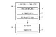
- the attention area detection mode image processing unit 64operates when it is set in the attention area detection mode. As shown in FIG. 6, the attention area detection mode image processing section 64 has a detection image processing section 70, an attention area detection section 71, and a cumulative detection time measurement section 72.
- the detection image processing unit 70sequentially obtains an endoscope image of the received Bc image signal, Gc image signal, and Rc image signal by performing image processing such as color conversion processing similar to that of the normal mode image processing unit 60.
- the attention area detection unit 71performs an image analysis of the endoscope image and performs an attention area detection process for detecting an attention area in the observation target.
- the attention area detection unit 71detects a lesion (for example, tumor or inflammation) in the observation target as the attention area.
- the attention area detection unit 71first divides the endoscope image into a plurality of small areas, for example, a square area of several pixels. Next, an image-like feature amount is calculated from the divided endoscope images. Subsequently, based on the calculated feature amount, a recognition process is performed to determine whether each small region is a lesion.
- a recognition processis preferably a machine learning algorithm such as a convolutional neural network (Convolutional Neural Network) or a deep learning (Deep Learning).
- the feature amount calculated from the endoscope image by the attention area detection unit 71is an index value obtained from the shape, color, or the shape or color of a predetermined portion in the observation target.
- the characteristic amountthe blood vessel density, the blood vessel shape, the number of blood vessel branches, the blood vessel thickness, the blood vessel length, the blood vessel meandering degree, the blood vessel depth, the gland duct shape, the gland duct opening shape, the gland duct
- the valueis at least one of the length, the degree of meandering of the gland duct, and the color information, or a value obtained by combining two or more thereof.
- the attention area detection unit 71associates information such as the position, size, and type of the extracted lesion with the endoscope image as a detection result.
- the attention area detection mode image processing unit 64outputs an endoscope image associated with the detection result to the display control unit 58.
- the total detection time measurement unit 72measures the total detection time during which the attention area is detected.
- the cumulative detection time measuring unit 72measures the time when the attention area detection unit 71 detects the attention area using a counter.
- the initial value of the counteris 0, and the counter value is incremented by one every time a clock signal of a predetermined cycle is input from the start of detection of the attention area by the attention area detection unit 71 (counter value + 1). Advancing this counter value by one means that the total detection time for each period of the counter is being measured.
- the cumulative detection time measuring unit 72outputs the counter value to the display control unit 58.
- the total detection time measurement unit 72outputs a counter value of 0 as the total detection time together with the endoscope image (the image of the start of detection of the attention area). Then, while the attention area is detected in the observation target, the cumulative detection time measuring unit 72 continues to output the counter value to the display control unit 58.
- the display control unit 58performs display control for displaying images and data from the image processing unit 56 on the monitor 18.
- the display control unit 58performs control to display a normal image on the monitor 18.
- the display control unit 58controls to display a special image on the monitor 18.
- the display control unit 58highlights the attention area detected by the attention area detection unit 71 on the endoscope image and measures the total detection time measurement unit 72. The highlighting is changed according to the total detected time.
- the display control unit 58includes an emphasis processing unit 73.
- the emphasis processing unit 73displays the endoscope image output from the attention area detection mode image processing unit 64 and an emphasized display for emphasizing the attention area based on the detection result associated with the endoscope image. Append to image.
- the display control unit 58performs the endoscopic processing in which the imaging sensor 38 captures an image and performs the image processing by the attention area detection mode image processing unit 64.
- the mirror image 75(an image similar to the normal image) is sequentially acquired and displayed on the display screen 76 of the monitor 18 in real time. In this case, there is no highlighting.
- the enhancement processing unit 73From the detection results associated with the endoscope image 75, an image of a figure based on information on the position and size of the lesion is generated. Then, the emphasis processing unit 73 superimposes and displays a graphic as an emphasis display at the position of the lesioned part of the endoscope image 75.
- the display control unit 58displays a rectangular frame-shaped figure 77 surrounding the lesion 78 as highlighting.
- the display control unit 58displays the graphic 77 as the highlighted display, and changes the highlighted display according to the cumulative detection time measured by the cumulative detection time measuring unit 72 as described above. Specifically, the transmittance of the graphic 77 is changed according to the total detection time. As the transmittance increases, the endoscope image 75 can be seen through the graphic 77. When the transmittance is 100%, the figure 77 is completely invisible and cannot be seen, and when the transmittance is 0%, the portion where the figure 77 is superimposed on the endoscope image 75 is completely invisible. become. As shown in FIG.
- the emphasis amount of the graphic 77is set to the maximum, that is, the transparency of the graphic 77 is set to 0%.
- the total detection time measured by the total detection time measuring unit 72is 0.
- the emphasis amount of the graphic 77is gradually reduced, that is, the transparency of the graphic 77 is gradually increased in accordance with the increase of the total detection time.
- the height of the transparency of the graphic 77is represented by the size of the hatched pattern applied to the graphic 77.
- the figure 77 in FIG. 7 (B)has a larger shaded area than the figure 77 in FIG. 7 (C).
- the height of the transmittance in FIG. 7Cis proportional to the total detection time (counter value) output simultaneously when the endoscopic image 75 shown in FIG. 7C is output. .
- the cumulative detection time measuring unit 72stops measuring the total detection time, and the highlighting by the highlighting processing unit 73 stops. Then, the cumulative detection time measuring unit 72 resets the cumulative detection time, and starts measuring the cumulative detection time from the initial value (the counter value is 0) when a lesion as the attention area is detected next.
- the doctoroperates the mode switching unit 13c to switch to the attention area detection mode (S11).
- the observation targetis illuminated with the illumination light for the attention area detection mode.
- the observation target illuminated with the illumination light for the attention area detection modeis imaged by the imaging sensor 38 to obtain an endoscope image.
- the display control unit 58displays the endoscope image 75 on the display screen 76 of the monitor 18 in real time (S12).
- attention area detection processing for detecting the attention area in the observation target by the attention area detection unit 71is performed on the acquired endoscope image (S13).
- the detection resultis output in association with the endoscope image, and the total detection time measurement unit 72 measures and outputs the total detection time in which the attention area is detected. (S15).
- the emphasis processing unit 73displays the graphic 77 as the highlighted display, and changes the graphic 77 according to the cumulative detection time measured by the cumulative detection time measuring unit 72 ( S16).
- the measurement of the total detection time and the highlighting according to the total detection timeare continued as long as the attention area is detected (N in S17).
- the detection of the attention areais stopped (Y in S17)
- the measurement of the total detection time and the highlightingare stopped (S18).
- the emphasis amount of the emphasis displaygradually decreases in accordance with the cumulative detection time, and when the detection of the attention area from within the observation target stops, the emphasis display is also terminated, so that the emphasis display hinders the doctor's observation. None.
- the present inventionis not limited to this, and the case where a plurality of regions of interest are detected in the observation target is described.
- the total detection timemay be measured for each detected region of interest, and the display control unit 58 may change the highlighted display according to the total detection time of each region of interest.
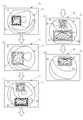
- 9 and 10show an example in which two regions of interest are detected while an observation target is imaged by the imaging sensor 38 and an endoscopic image is sequentially acquired.
- the first lesion 81is detected as a region of interest as shown in FIGS. 9A to 9D, and thereafter, as shown in FIGS. 9C to 9E.
- the second lesion 82is detected as a region.
- the endoscope images shown in FIGS. 9A to 9E and the endoscope images shown in FIGS. 10A to 10Eindicate the same image, and The images are arranged in chronological order obtained by imaging at 38.
- the cumulative detection time measuring unit 72measures the cumulative detection time for each of the first lesion 81 and the second lesion 82.
- the time t10 at which the endoscope image 75 shown in FIGS. 9A and 10A is acquiredindicates that the detection of the first lesion 81 is started.
- the first cumulative detection time T1is 0, and the emphasis amount of the frame-shaped figure 83 as the emphasis display of the first lesion 81 is maximized.
- the total detection time measuring unit 72starts measuring the first total detection time T1.
- the first cumulative detection time T1gradually increases.
- the emphasis amount of the graphic 83decreases.
- the first lesion 81disappears from the observation target.
- the attention area detection unit 71the measurement of the first total detection time T1 is stopped, and the display of the graphic 83 as the highlighted display is stopped.
- the cumulative detection time measuring unit 72resets the first cumulative detection time T1.
- the time t20 at which the endoscope image 75 shown in FIGS. 9C and 10C is acquiredindicates that the detection of the second lesion 82 is started.
- the second total detection time T2is 0, and the amount of emphasis on the frame-shaped figure 84 as the emphasis display of the second lesion 82 is maximized.
- the total detection time measuring unit 72measures the first total detection time T1.
- the emphasis amount of the graphic 83gradually decreases as the second cumulative detection time T2 increases.
- the second lesion 82disappears from the endoscope image 75 at time t21 after the endoscope image 75 shown in FIG.
- the display control unit 58changes the highlighting in accordance with the total detection times T1 and T2 for each attention area, the doctor who is the user reliably identifies the first and second lesions 81 and 82. Can be observed separately, and the efficiency of observation can be improved. Furthermore, when the observation of the lesion has been completed, the highlighting has disappeared, so that a new lesion can be prevented from being overlooked.
- the enhancement amountis the same, attention is directed to the first lesion 81, although there is a possibility that the second lesion 82 may be overlooked, according to the present invention, when the observation of the first lesion 81 is completed, the amount of enhancement is reduced, so that the second lesion 82 may be overlooked. Can be highlighted, and oversight can be prevented.
- the attention area detection mode image processing section 64has an attention area storage section 86 and an identical attention area determination section 87.
- the attention area storage unit 86stores the total detection time of each attention area detected in the past by the attention area detection unit 71 in association with feature amount information indicating the feature amount of each attention area.
- the attention area storage unit 86is configured using a writable recording medium such as a RAM, an EEPROM, or a hard disk.
- the same attention area determination unit 87determines a past value based on the similarity between any of the attention area feature amounts stored in the attention area storage unit 86 and the attention area feature amount newly detected by the attention area detection unit 71. It is determined whether it is the same as any of the detected attention areas.
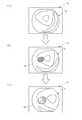
- a caseis described in which the lesion 88A as a region of interest detected in the past is the same as the lesion 88B as a region of interest newly detected.
- the endoscope images shown in FIGS. 12A to 12Eare arranged in chronological order.
- the lesion 88Ais a region of interest that is detected for the first time while sequentially acquiring the endoscope image, and the same determination is not performed as in the case where the lesion 88B described later is detected. Not done.
- the time t110 at which the endoscope image 75 shown in FIG. 12A is acquiredindicates that the detection of the lesion 88A is started.
- the total detection time T11is 0, and the emphasis amount of the graphic 89A as the emphasis display of the lesion 88A is the maximum.
- the cumulative detection time measuring unit 72starts measuring the cumulative detection time T11 from time t110.
- the emphasis amount of FIG. 89Agradually decreases as the total detection time T11 increases.
- the lesioned part 88Ais not detected. That is, at the time t111, the measurement of the total detection time T11 is temporarily stopped, and the display of the graphic 89A as the highlighted display disappears.
- the attention area detection mode image processing unit 64calculates the cumulative detection time T11 of the diseased part 88A measured by the cumulative detection time measuring unit 72 and the characteristic amount representing the characteristic amount of the diseased part 88A.
- the informationis stored in the attention area storage unit 86 in association with the information.
- the feature amount informationis, for example, an image feature amount such as a pixel value of an RGB image signal.
- the feature amount informationis not limited to this, and may be information such as the position, size, and shape of the attention area.
- the state where the attention area is not detectedcontinues, and the lesion 88B is detected at the time t120. That is, the time t120 at which the endoscope image 75 shown in FIG. 12D is acquired indicates that the detection of the lesion 88B is started.
- the same attention area determination unit 87determines whether any one of the feature amounts of the attention area stored in the attention area storage unit 86 and the attention area detection unit 71 From the similarity with the feature amount of the newly detected attention area, it is determined whether or not it is the same as any of the attention areas detected in the past. That is, when the similarity between the two feature amounts is high (more than a specific threshold), it is determined that they are the same, and when the similarity is low (below a specific threshold), it is determined that they are not the same.
- the feature amount of the lesion 88A stored in the attention area storage unit 86 and the feature of the lesion 88B newly detected by the attention area detection unit 71are described.
- the similarity with the amountis high, and the same attention area determination unit 87 determines that the lesioned part 88A and the lesioned part 88B are the same.
- the cumulative detection of the past lesioned part 88A determined to be the sameis performed.
- the measurementis carried out taking over the time T11. That is, the cumulative detection time measurement unit 72 measures the cumulative detection time by taking over the cumulative detection time T11 from the time t120 at which the endoscopic image 75 shown in FIG. 12D is obtained and the lesion 88B is detected. . Accordingly, the actual total detection time is the sum of the total detection time T11 and the total detection time T12 from time t120.
- the cumulative detection time measuring unit 72resumes the measurement by taking over the cumulative detection time T11.
- the emphasis amount of FIG. 89Bgradually decreases as the cumulative detection time (T11 + T12) increases.
- the lesioned part 88Bdisappears from the endoscope image 75.
- the measurement of the total detection time (T11 + T12)temporarily stops, and the display of the graphic 89B as the highlighted display disappears.
- the attention area detection mode image processing unit 64associates the cumulative detection time (T11 + T12) of the lesion 88B with the feature information indicating the feature of the attention area 81B and associates the attention area with the attention area.
- the informationis stored in the storage unit 86.
- the total detection time measurement unit 72resets the total detection time. Then, the measurement is started from the initial value (the counter value is 0).
- the cumulative detection time taken over from the past attention areais determined for the attention area determined to be the same by taking over and measuring the cumulative detection time of the past attention area determined to be the same. Since the highlighting is performed according to the time, the doctor can easily recognize that the same attention area as the past attention area is detected.
- the cumulative detection time for the region of interest in the pastis taken over and measured. Does not take over the total detection time in all cases where it is determined that they are the same, even if it is determined that they are the same, the latest detection time of the past detected region of interest and the newly detected If the time interval from the detection time of the attention area is larger than a predetermined value, the measurement may be started after resetting the total detection time.
- a lesion 90A as a region of interest detected in the pastis the same as a lesion 90B as a region of interest newly detected.
- the endoscope images shown in FIGS. 13A to 13Eare arranged in chronological order.
- the lesion 90Ais a region of interest detected for the first time while sequentially acquiring the endoscope image, and the same determination is not performed as in the case where the lesion 90B described later is detected. Not done.
- the time t210 at which the endoscope image 75 shown in FIG. 13A is acquiredindicates that the detection of the lesion 90A is started.
- the cumulative detection time T21is 0, and the emphasis amount of the graphic 91A as the emphasis display of the lesion 90A is the maximum.
- the cumulative detection time measuring unit 72starts measuring the cumulative detection time T21 from time t210.
- the emphasis amount of the graphic 91Agradually decreases as the total detection time T21 increases.
- the lesion 90Ais not detected. That is, at this time t211, the measurement of the cumulative detection time T21 is temporarily stopped, and the display of the graphic 91A as the highlighted display disappears.
- the attention area detection mode image processing unit 64calculates the total detection time T21 of the lesion 90A measured by the total detection time measurement unit 72 and the feature amount of the lesion 90A.
- the feature amount information to be expressedis associated with the latest detection time t211 of the lesion 90A and stored in the attention area storage unit 86.
- the attention area detection mode image processing unit 64performs the same operation as any of the attention areas detected in the past, as in the third embodiment.
- a time interval TL between the latest detection time t211 of the lesion 90A detected in the past and the detection time t220 of the newly detected lesion 90Bis compared with a predetermined value.
- the predetermined valueindicates that the region of interest is reflected in the endoscope image 75, for example, the entire image is dark or the focus of the imaging sensor 38 is not attained because of the performance of the device. Is set assuming the case where cannot be detected. Therefore, the predetermined value to be compared with the above-described time interval TL is assumed to be a very short time from when the attention area cannot be detected due to the performance of the device to when the attention area is restored to the detectable state. Is set.
- the total detection time measuring unit 72resets the total detection time and starts measurement from an initial value (the counter value is 0).
- the cumulative detection time measuring unit 72measures the cumulative detection time T22 from time t220 when the endoscopic image 75 shown in FIG. 13D is acquired and the lesion 90B is detected.
- the cumulative detection time T22is 0, and the emphasis amount of the graphic 91B as the emphasis display of the lesion 90B is the maximum.
- the emphasis amount of the graphic 91Bgradually decreases as the total detection time T22 increases.
- the lesion 90Bdisappears from the endoscope image 75.
- the measurement of the cumulative detection time T22is temporarily stopped, and the display of the graphic 91B as the highlighted display disappears.
- the attention area detection mode image processing unit 64calculates the total detection time T22 of the lesion 90B measured by the total detection time measurement unit 72 and the characteristic amount representing the characteristic amount of the lesion 90B.
- the informationis associated with the latest detection time t221 of the lesion 90B and stored in the attention area storage unit 86.
- the attention areais newly detected again after time t221, it is determined whether or not they are the same as above, and the time interval between the detection times is compared with a predetermined value.
- the previously detected lesion 90A and the newly detected lesion 90Bare determined to be the same, and the time interval TL between the most recent detection time and the newly detected detection time is less than a predetermined value.
- the cumulative detection time T21 regarding the past lesion 90A determined to be the sameis taken over and measured.
- the attention area detection unit 71determines that the attention area newly detected is not the same as any of the attention areas detected in the past, the accumulated detection time is set to the same as in the third embodiment. Reset and start measurement from the initial value (counter value is 0).
- the insertion portion 12aIn the endoscopy, first, after inserting the insertion portion 12a to a position where it can be inserted into the lumen, the insertion portion 12a is gradually pulled out from the lumen, and follows the same path as that at the time of insertion in the opposite direction. While searching for a lesion, there is a possibility that a lesion once detected during insertion may be detected again when extracted. In the present embodiment, even when it is determined that the region of interest detected in the past and the region of interest newly detected are the same, the time between the latest detection time and the detection time when the region is newly detected is determined. If the interval TL is larger than the predetermined value, the cumulative detection time measuring unit 72 resets the cumulative detection time and starts measurement from the initial value (the counter value is 0).
- the emphasis amountis the maximum, so that it is possible to prevent the doctor from overlooking the attention area.
- the cumulative detection timeis reset if the time interval is larger than the predetermined value.
- the present inventionis not limited to this.
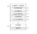
- the attention area detection mode image processing unit 64includes a treatment recognition unit 92.
- the treatment recognition unit 92monitors the gas / liquid injection from the air / water nozzle as a specific treatment performed during imaging, and receives a signal when the air / water operation unit 13e is operated. To recognize that a particular action has been taken.
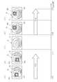
- FIG. 15an example is given in which the previously detected lesion 93A as a region of interest is the same as the newly detected lesion 93B as a region of interest.
- the endoscope images shown in FIGS. 15A to 15Eare arranged in chronological order.
- the time t311 at which the endoscope image 75 shown in FIG. 15C is acquiredis the time at which the treatment recognizing unit 92 recognizes that the gas / liquid injection as the specific treatment has been performed. Since the treatment recognizing unit 92 recognizes the specific treatment, the cumulative detection time measuring unit 72 stops measuring the cumulative detection time T31 and resets the cumulative detection time. For this reason, the display of the graphic 94A as the highlight display is eliminated. After time t311, the state where the specific treatment is being performed (the state shown in FIG. 15C) continues until immediately before time t320. Also in this embodiment, it is determined whether or not the attention areas are the same as in the third and fourth embodiments, and if it is determined that they are the same, the cumulative detection time is taken over under certain conditions. May be performed, but when a specific treatment is recognized, the cumulative detection time is reset with priority regardless of the case where it is determined that the attention areas are the same.
- the lesion 93Bis detected. That is, the time t320 at which the endoscope image 75 shown in FIG. 15D is acquired indicates that the detection of the lesion 93B is started. As shown in FIG. 15D, at time t320, the cumulative detection time T32 is 0, and the amount of emphasis on the graphic 94B as the emphasis display of the lesion 93B is maximized. As shown in FIGS. 15D and 15E, the emphasis amount of the graphic 94B gradually decreases as the total detection time T32 increases. At time t321 after the endoscope image 75 shown in FIG. 15E is acquired, the lesion 93B disappears from the endoscope image 75.
- the cumulative detection time measuring unit 72resets the cumulative detection time and starts measurement from an initial value (the counter value is 0).
- the enhancement amountis maximum, so that it is possible to prevent the doctor from overlooking the attention area.
- the ejection of gas or liquidis taken as an example of the specific treatment, but the present invention is not limited to this, and any specific treatment that affects the endoscope image such as treatment with a treatment tool is applied. be able to.
- the operation unitreceives and recognizes a signal.
- the present inventionis not limited to this.
- the specific treatmentmay be recognized by image analysis of the above.
- the display control unit 58changes the transmittance of the graphic as the highlighted display when changing the highlighted display according to the cumulative detection time. May be changed from a specific color to another specific color, for example, from green to red.
- the shape of the figuremay be changed instead of the transparency or color of the figure.
- FIG.May be displayed, and the thickness of the frame-shaped figure may be changed according to the total detection time.
- the display control unit 58surrounds the lesion 95 as highlighting.
- a frame-shaped figure 96is displayed, and the highlighting is changed according to the total detection time measured by the total detection time measuring unit 72.
- the display control unit 58maximizes the emphasis amount of the figure 96, that is, the thickness of the frame of the figure 96 when starting detection of the lesion 95 as the attention area. To the maximum.
- the total detection time measured by the total detection time measuring unit 72is 0.
- the display control unit 58gradually reduces the emphasis amount of the graphic 77, that is, gradually reduces the thickness of the frame of the graphic 96 according to the increase of the cumulative detection time.
- the graphic to be highlightedis a rectangular frame.
- the present inventionis not limited to this.
- the display control unit 58superimposes and displays a frame-shaped figure at the position of the attention area as highlighting, but is not limited to this, and changes the color of the attention area as highlighting, The color before the change may be gradually returned according to the cumulative detection time.
- the display control unit 58uses the lesion 97 as an emphasized display.
- a color different from the above colorfor example, a color that is largely contained in the lesion 97 is extracted, replaced with a color having a different hue and displayed, and according to the total detection time measured by the total detection time measuring unit 72.
- Change highlightingMore specifically, as shown in FIG. 17B, the display control unit 58 starts the detection of the lesion 95 as a region of interest, for example, when the lesion 97 contains many red portions.
- the red part of the lesion 97is replaced with green having a completely different hue and displayed.
- the state in which the hue of the lesion 97 has been replaced with a completely different coloris regarded as the state in which the enhancement amount is the maximum. In this case, the total detection time measured by the total detection time measuring unit 72 is 0.
- the display control unit 58gradually reduces the emphasis amount of the lesion 97 in accordance with the increase of the cumulative detection time, that is, the part of the lesion 97 where the color is replaced is changed from green. It gradually returns to the color close to red before the change.
- the difference between the color of the lesion 97 and the color before the changeis represented by the fineness of the hatched area applied to the lesion 97.
- the lesion 97 in FIG. 17Bhas a finer shade than the lesion 97 in FIG. 17C.
- the present inventionis not limited to this. It may be highlighted.
- the highlighting of the lesion 97is not limited to these, and image processing that can be visually distinguished from the surroundings, such as hue change processing, saturation change processing, contrast processing, negative / positive inversion processing, and filtering processing. Should be fine.
- the highlighting by the pixel value of the lesion 97 and the highlighting by the figure surrounding the lesion in the above embodimentsmay be combined.
- the observation targetis illuminated using the four-color LEDs 20a to 20d, but the observation target may be illuminated using a laser light source and a phosphor. In each of the above embodiments, the observation target is illuminated using the four-color LEDs 20a to 20d. However, the observation target may be illuminated using a white light source such as a xenon lamp and a rotating filter. Further, instead of the color image sensor 38, a monochrome image sensor may be used to image the observation target.
- the medical image processing apparatus of the present inventionis applied to an endoscope system that acquires an endoscope image as a medical image.
- various endoscopessuch as a capsule endoscope are used.
- the medical image processing apparatus of the present inventioncan be applied to various medical image apparatuses.
- the hardware structure of the processing unit (processing unit) that executes various types of processingis the following various types of processors.
- the various processorsinclude a general-purpose processor (Central Processing Unit), a GPU (Graphical Processing Unit), an FPGA (Field Programmable Gate Array), which is a general-purpose processor that executes software (programs) and functions as various processing units.
- a programmable logic deviceProgrammable Logic Device: PLD
- PLDprogrammable Logic Device
- One processing unitmay be configured by one of these various processors, or a combination of two or more processors of the same type or different types (for example, a plurality of FPGAs, a combination of a CPU and an FPGA, or a CPU). And a combination of a GPU and the like. Further, a plurality of processing units may be configured by one processor. As an example in which a plurality of processing units are configured by one processor, first, as represented by a computer such as a client or a server, one processor is configured by a combination of one or more CPUs and software, There is a form in which this processor functions as a plurality of processing units.
- SoCSystem-On-Chip
- SoCSystem-On-Chip
- the hardware structure of these various processorsis more specifically an electric circuit (circuitry) in which circuit elements such as semiconductor elements are combined.
Landscapes
- Health & Medical Sciences (AREA)
- Life Sciences & Earth Sciences (AREA)
- Surgery (AREA)
- Engineering & Computer Science (AREA)
- Physics & Mathematics (AREA)
- Optics & Photonics (AREA)
- Biomedical Technology (AREA)
- General Health & Medical Sciences (AREA)
- Pathology (AREA)
- Nuclear Medicine, Radiotherapy & Molecular Imaging (AREA)
- Biophysics (AREA)
- Heart & Thoracic Surgery (AREA)
- Medical Informatics (AREA)
- Molecular Biology (AREA)
- Animal Behavior & Ethology (AREA)
- Radiology & Medical Imaging (AREA)
- Public Health (AREA)
- Veterinary Medicine (AREA)
- Signal Processing (AREA)
- Astronomy & Astrophysics (AREA)
- General Physics & Mathematics (AREA)
- Endoscopes (AREA)
- Instruments For Viewing The Inside Of Hollow Bodies (AREA)
Abstract
Description
Translated fromJapanese本発明は、病変部などの注目領域を検出するための医療用画像処理装置及び内視鏡システム並びに医療用画像処理装置の作動方法に関する。The present invention relates to a medical image processing device and an endoscope system for detecting a region of interest such as a lesion, and an operation method of the medical image processing device.
医療分野においては、内視鏡画像、X線画像、CT(Computed Tomography)画像、MR(Magnetic Resonanse)画像などの医用画像を用いて、患者の病状の診断や経過観察などの画像診断が行われている。このような画像診断に基づいて、医師などは治療方針の決定などを行っている。In the medical field, medical diagnosis such as endoscopic images, X-ray images, CT (Computed Tomography) images, and MR (Magnetic Resonanse) images are used to perform image diagnosis such as diagnosis of disease states and follow-up observations of patients. ing. Based on such image diagnosis, doctors and the like make decisions on treatment policies and the like.
近年、医用画像を用いた画像診断においては、医用画像を解析して臓器内の病変や腫瘍など注意して観察すべき注目領域を自動的に検出することが行われつつある。特に、ディープラーニングなどの機械学習を行うことによって、注目領域を検出する精度が飛躍的に向上している。In recent years, in image diagnosis using medical images, a medical image is analyzed to automatically detect a region of interest to be observed carefully, such as a lesion or a tumor in an organ. In particular, by performing machine learning such as deep learning, the accuracy of detecting a region of interest has been dramatically improved.
特許文献1には、医用画像から病変部などの注目領域を検出した場合、検出結果に基づいて画像処理を行う医用画像処理装置が記載されている。この特許文献1記載の医用画像処理装置では、注目領域が検出された場合、表示態様を変更する経過時間を設定し、この設定された経過時間が経過するまでの間、注目領域に対するアラート情報が付加または重畳などされた表示画像が生成されて、表示部に表示される。Patent Document 1 describes a medical image processing apparatus that performs image processing based on a detection result when a region of interest such as a lesion is detected from a medical image. In the medical image processing apparatus described in Patent Document 1, when an attention area is detected, an elapsed time for changing the display mode is set, and until the set elapsed time, alert information for the attention area is displayed. A display image added or superimposed is generated and displayed on the display unit.
しかしながら、特許文献1記載の医用画像処理装置では、注目領域が検出された場合、設定された経過時間が経過するまでの間は、アラート情報を表示する。この場合、医用画像内に注目領域が存在しなくなっても、経過時間が経過するまでは、アラート情報を表示し続けることになるため、医師が観察を行う際、医用画像内に既に存在しない注目領域を探してしまうという事態が起こり、アラート情報が医師による観察の妨げになる可能性がある。However, in the medical image processing device described in Patent Literature 1, when a region of interest is detected, alert information is displayed until a set elapsed time elapses. In this case, even if the attention area no longer exists in the medical image, the alert information will continue to be displayed until the elapsed time elapses. A situation may occur where an area is searched for, and the alert information may hinder observation by a doctor.
本発明は、注目領域の検出に基づく表示が医用画像の観察の妨げとなることを防止することが可能な医用画像処理装置及び内視鏡システム並びに医用画像処理装置の作動方法を提供することを目的とする。The present invention provides a medical image processing apparatus, an endoscope system, and a method of operating a medical image processing apparatus that can prevent a display based on detection of a region of interest from obstructing observation of a medical image. Aim.
本発明の医用画像処理装置は、医用画像取得部と、注目領域検出部と、累計検出時間計測部と、表示制御部とを有する。医用画像取得部は、観察対象を撮像部で撮像して医用画像を取得する。注目領域検出部は、医用画像取得部により取得した医用画像に対して観察対象内の注目領域を検出する。累計検出時間計測部は、注目領域が検出されている累計検出時間を計測する。表示制御部は、医用画像に対して注目領域検出部により検出した注目領域を強調表示させる表示制御部であって、累計検出時間に応じて強調表示を変化させる。The medical image processing device of the present invention includes a medical image acquisition unit, a region of interest detection unit, a cumulative detection time measurement unit, and a display control unit. The medical image acquisition unit acquires a medical image by imaging an observation target with an imaging unit. The attention area detection unit detects an attention area in the observation target with respect to the medical image acquired by the medical image acquisition unit. The total detection time measuring unit measures the total detection time during which the attention area is detected. The display control unit is a display control unit that highlights the attention area detected by the attention area detection unit on the medical image, and changes the highlight display according to the total detection time.
表示制御部は、注目領域の検出開始の際、強調表示の強調量が最大となり、累計検出時間の増加に応じて強調量を徐々に低下させることが好ましい。(4) It is preferable that the display control unit maximizes the emphasis amount of the emphasis display at the start of the detection of the attention area, and gradually decreases the emphasis amount as the total detection time increases.
累計検出時間計測部は、撮像部による撮像中に、注目領域検出部により複数の注目領域が検出された場合、検出された注目領域毎に累計検出時間を計測し、表示制御部は注目領域毎の累計検出時間に応じて強調表示を変化させることが好ましい。The cumulative detection time measuring unit measures the cumulative detection time for each detected region of interest when the region of interest is detected by the region of interest detection unit during imaging by the imaging unit. It is preferable to change the highlighting in accordance with the total detection time.
注目領域検出部により過去検出された注目領域毎の累計検出時間と注目領域毎の特徴量を表す特徴量情報とを関連付けて記憶する注目領域記憶部と、注目領域記憶部に記憶された注目領域の特徴量のいずれかと注目領域検出部により新たに検出された注目領域の特徴量との類似度から、過去検出された注目領域のいずれかと同一であるか否かを判定する同一注目領域判定部と、を有し、累計検出時間計測部は、撮像部による撮像中に、同一注目領域判定部により過去検出された注目領域のいずれかと同一であると判定された場合、同一であると判定された過去の注目領域に関する累計検出時間を引き継いで計測し、同一注目領域判定部により過去検出された注目領域のいずれとも同一ではないと判定された場合、注目領域検出部により新たに検出された注目領域に関して累計検出時間をリセットしてから計測開始することが好ましい。An attention area storage unit that stores the total detection time of each attention area detected in the past by the attention area detection unit in association with feature amount information representing a feature amount of each attention area, and an attention area stored in the attention area storage unit From the similarity between any one of the feature amounts of interest and the feature amount of the attention region newly detected by the attention region detection unit, the same attention region determination unit that determines whether it is the same as any of the attention regions detected in the past The cumulative detection time measurement unit is determined to be the same when it is determined during the imaging by the imaging unit that any of the attention regions detected in the past by the same attention region determination unit is the same. The total detection time for the past attention area is taken over and measured, and if the same attention area determination unit determines that it is not the same as any of the attention areas detected in the past, the attention area detection unit It is preferred to start measurement is reset the cumulative detection time with respect to the detected region of interest.
注目領域記憶部は、過去検出された各注目領域毎の直近の検出時刻を累計検出時間及び特徴量情報に関連付けて記憶し、累計検出時間計測部は、撮像部による撮像中に、新たに検出された注目領域が同一注目領域判定部により過去検出された注目領域のいずれかと同一であると判定された場合であり、かつ直近の検出時刻と、注目領域が新たに検出された検出時刻との時間間隔が所定値より大きい場合に、注目領域検出部により新たに検出された注目領域に関して累計検出時間をリセットしてから計測開始することが好ましい。The attention area storage unit stores the latest detection time of each attention area detected in the past in association with the total detection time and the feature amount information, and the total detection time measurement unit newly detects during the imaging by the imaging unit. This is a case where the same attention area is determined by the same attention area determination unit to be the same as any of the attention areas detected in the past, and the most recent detection time and the detection time when the attention area is newly detected. When the time interval is larger than the predetermined value, it is preferable that the measurement is started after resetting the total detection time for the attention area newly detected by the attention area detection unit.
観察対象内で特定の処置が行われたことを認識する処置認識部を備え、累計検出時間計測部は、撮像部による撮像中に、処置認識部により特定の処置が行われたことを認識した場合に、注目領域検出部により新たに検出された注目領域に関して累計検出時間をリセットしてから計測開始することが好ましい。A treatment recognition unit that recognizes that a specific treatment has been performed in the observation target has been provided, and the cumulative detection time measurement unit has recognized that the specific treatment has been performed by the treatment recognition unit during imaging by the imaging unit. In this case, it is preferable to start the measurement after resetting the total detection time for the attention area newly detected by the attention area detection unit.
表示制御部は、強調表示として、医用画像内の注目領域の位置に図形を重畳表示することがこのましい。また、表示制御部は、累計検出時間に応じて強調表示として表示する図形の色を変化させることが好ましい。さらにまた、表示制御部は、累計検出時間に応じて注目領域に重畳させる図形の透過度を変化させることが好ましい。(4) It is preferable that the display control unit superimposes and displays a figure at the position of the attention area in the medical image as the highlight display. Further, it is preferable that the display control unit changes the color of the graphic displayed as the highlighted display according to the total detection time. Furthermore, it is preferable that the display control unit changes the transparency of the graphic to be superimposed on the attention area according to the total detection time.
表示制御部は、累計検出時間に応じて強調表示として表示する図形の形状を変化させることが好ましい。また、表示制御部は、強調表示として、注目領域を囲む枠形状の図形を表示させ、累計検出時間に応じて図形の枠の太さを変化させることが好ましい。(4) It is preferable that the display control unit changes the shape of the graphic displayed as the highlighted display according to the total detection time. Further, it is preferable that the display control section displays a frame-shaped figure surrounding the attention area as highlighting, and changes the thickness of the frame of the figure according to the total detection time.
表示制御部は、注目領域の色の変更により強調表示を行い、累計検出時間に応じて注目領域の変更前の色に戻すことが好ましい。(4) It is preferable that the display control unit performs highlighting by changing the color of the attention area, and returns to the color before the change of the attention area according to the total detection time.
本発明の内視鏡システムは、光源装置と、内視鏡と、医用画像取得部と、累計検出時間計測部と、表示制御部と、表示部とを備える。光源装置は、観察対象を照明するための照明光を発する。内視鏡は、照明光で照明された観察対象を撮像する撮像部を有する。医用画像取得部は、撮像部で観察対象を撮像して得られる医用画像を取得する。注目領域検出部は、医用画像取得部により取得した医用画像に対して観察対象内の注目領域を検出する。累計検出時間計測部は、注目領域が検出されている累計検出時間を計測する。表示制御部は、医用画像に対して注目領域検出部により検出した注目領域を強調表示させる表示制御部であって、累計検出時間に応じて強調表示を変化させる。表示部は、医用画像及び強調表示を表示する。内 The endoscope system of the present invention includes a light source device, an endoscope, a medical image acquisition unit, a cumulative detection time measurement unit, a display control unit, and a display unit. The light source device emits illumination light for illuminating an observation target. The endoscope includes an imaging unit that captures an image of an observation target illuminated with illumination light. The medical image acquisition unit acquires a medical image obtained by imaging the observation target with the imaging unit. The attention area detection unit detects an attention area in the observation target with respect to the medical image acquired by the medical image acquisition unit. The total detection time measuring unit measures the total detection time during which the attention area is detected. The display control unit is a display control unit that highlights the attention area detected by the attention area detection unit on the medical image, and changes the highlight display according to the total detection time. The display unit displays the medical image and the highlighted display.
本発明の医療用画像処理装置の作動方法は、医用画像取得部が、観察対象を撮像部で撮像して医用画像を取得するステップと、認識処理部が、医用画像取得部により取得した医用画像に対して観察対象内の注目領域を検出するステップと、累計検出時間計測部が、注目領域が検出されている累計検出時間を計測するステップと、表示制御部が、医用画像に対して注目領域検出部により検出した注目領域を強調表示させ、累計検出時間に応じて強調表示を変化させるステップとを含んでいる。An operation method of the medical image processing apparatus according to the present invention includes a step of acquiring a medical image by capturing an observation target with an imaging unit, and a medical image acquired by the medical image acquiring unit. Detecting the region of interest in the observation target with respect to the step of measuring the total detection time in which the region of interest is detected, and the display control unit Highlighting the attention area detected by the detection unit and changing the highlighting according to the total detection time.
本発明によれば、注目領域の検出に基づく表示が医用画像の観察を妨げとなることを防止することができる。According to the present invention, it is possible to prevent the display based on the detection of the attention area from obstructing the observation of the medical image.
[第1実施形態]
図1に示すように、内視鏡システム10は、内視鏡12と、光源装置14と、プロセッサ装置16と、モニタ18(表示部)と、コンソール19とを有する。内視鏡12は、光源装置14と光学的に接続し、かつ、プロセッサ装置16と電気的に接続する。内視鏡12は、被検体内に挿入する挿入部12aと、挿入部12aの基端部分に設けた操作部12bと、挿入部12aの先端側に設けた湾曲部12c及び先端部12dを有している。操作部12bのアングルノブ13aを操作することにより、湾曲部12cが湾曲動作する。この湾曲動作によって、先端部12dが所望の方向に向けられる。[First Embodiment]
As shown in FIG. 1, the
先端部12dは、先端面に、照明窓と、観察窓と、送気・送水ノズルと、鉗子出口とを有する(いずれも図示無し)。照明窓は、照明光を観察部位に照射するためのものである。観察窓は、観察部位からの光を取り込むためのものである。送気・送水ノズルは、照明窓及び観察窓を洗浄するためのものである。鉗子出口は、鉗子と電気メス等の処置具を用いて各種処置を行うためのものである。The
また、操作部12bには、アングルノブ13aの他、静止画像の取得操作に用いる静止画像取得部13b、観察モードの切り替え操作に用いるモード切替部13c、ズーム倍率の変更操作に用いるズーム操作部13d、送気・送水操作部13eを設けている。静止画像取得部13bは、モニタ18に観察対象の静止画像を表示するフリーズ操作と、ストレージに静止画像を保存するレリーズ操作が可能である。送気・送水操作部13eは、先端部12dの送気・送水ノズルから気体・液体を噴射して照明窓及び観察窓を洗浄する噴射操作が可能である。The
内視鏡システム10は、観察モードとして、通常モードと、特殊モードと、注目領域検出モードとを有している。観察モードが通常モードである場合、複数色の光を通常モード用の光量比Lcで合波した通常光を発光する。また、観察モードが特殊モードである場合、複数色の光を特殊モード用の光量比Lsで合波した特殊光を発光する。The
また、観察モードが注目領域検出モードである場合、注目領域検出モード用照明光を発光する。本実施形態では、注目領域検出モード用照明光として、通常光を発光するが、特殊光を発光するようにしてもよい。When the observation mode is the attention area detection mode, the illumination light for the attention area detection mode is emitted. In the present embodiment, the normal light is emitted as the illumination light for the attention area detection mode, but a special light may be emitted.
プロセッサ装置16は、モニタ18及びコンソール19と電気的に接続する。モニタ18は、観察対象の画像や、画像に付帯する情報等を出力表示する。コンソール19は、注目領域(ROI : Region Of Interest)の指定等や機能設定等の入力操作を受け付けるユーザインタフェースとして機能する。The
図2に示すように、光源装置14は、観察対象の照明に用いる照明光を発する光源部20と、光源部20を制御する光源制御部22とを備えている。光源部20は、複数色のLED(Light Emitting Diode)等の半導体光源である。光源制御部22は、LED等のオン/オフや、LED等の駆動電流や駆動電圧の調整によって、照明光の発光量を制御する。また、光源制御部22は、光学フィルタの変更等によって、照明光の波長帯域を制御する。As shown in FIG. 2, the
第1実施形態では、光源部20は、V-LED(Violet Light Emitting Diode)20a、B-LED(Blue Light Emitting Diode)20b、G-LED(Green Light Emitting Diode)20c、及びR-LED(Red Light Emitting Diode)20dの4色のLEDと、波長カットフィルタ23とを有している。図3に示すように、V-LED20aは、波長帯域380nm~420nmの紫色光Vを発する。In the first embodiment, the
B-LED20bは、波長帯域420nm~500nmの青色光Bを発する。B-LED23bから出射した青色光Bのうち少なくともピーク波長の450nmよりも長波長側は、波長カットフィルタ23によりカットされる。これにより、波長カットフィルタ23を透過した後の青色光Bxは、420~460nmの波長範囲になる。このように、460nmよりも長波長側の波長域の光をカットしているのは、この460nmよりも長波長側の波長域の光は、観察対象である血管の血管コントラストを低下させる要因であるためである。なお、波長カットフィルタ23は、460nmよりも長波長側の波長域の光をカットする代わりに、460nmよりも長波長側の波長域の光を減光させてもよい。The B-
G-LED20cは、波長帯域が480nm~600nmに及ぶ緑色光Gを発する。R-LED20dは、波長帯域が600nm~650nmに及び赤色光Rを発する。なお、各LED20a~20dから発せられる光は、それぞれの中心波長とピーク波長とが同じであっても良いし、異なっていても良い。The G-LED 20c emits green light G whose wavelength band extends from 480 nm to 600 nm. The R-
光源制御部22は、各LED20a~20dの点灯や消灯、及び点灯時の発光量等を独立に制御することによって、照明光の発光タイミング、発光期間、光量、及び分光スペクトルの調節を行う。光源制御部22における点灯及び消灯の制御は、観察モードごとに異なっている。なお、基準の明るさは光源装置14の明るさ設定部又はコンソール19等によって設定可能である。(4) The light source control unit 22 adjusts the light emission timing, the light emission period, the light amount, and the spectrum of the illumination light by independently controlling the lighting and extinguishing of each of the
通常モード又は注目領域検出モードの場合、光源制御部22は、V-LED20a、B-LED20b、G-LED20c、及びR-LED20dを全て点灯させる。その際、図4に示すように、紫色光V、青色光B、緑色光G、及び赤色光R間の光量比Lcは、青色光Bxの光強度のピークが、紫色光V、緑色光G、及び赤色光Rのいずれの光強度のピークよりも大きくなるように、設定されている。これにより、通常モード又は注目領域検出モードでは、光源装置14から、紫色光V、青色光Bx、緑色光G、及び赤色光Rを含む通常モード用又は注目領域検出モード用の多色光が、通常光として、が発せられる。通常光は、青色帯域から赤色帯域まで一定以上の強度を有しているため、ほぼ白色となっている。In the case of the normal mode or the attention area detection mode, the light source control unit 22 turns on all of the V-
特殊モードの場合、光源制御部22は、V-LED20a、B-LED20b、G-LED20c、及びR-LED20dを全て点灯させる。その際、図5に示すように、紫色光V、青色光B、緑色光G、及び赤色光R間の光量比Lsは、紫色光Vの光強度のピークが、青色光Bx、緑色光G、及び赤色光Rのいずれの光強度のピークよりも大きくなるように、設定されている。また、緑色光G及び赤色光Rの光強度のピークは、紫色光V及び青色光Bxの光強度のピークよりも小さくなるように、設定されている。これにより、特殊モードでは、光源装置14から、紫色光V、青色光Bx、緑色光G、及び赤色光Rを含む特殊モード用の多色光が、特殊光として発せられる。特殊光は、紫色光Vが占める割合が大きいことから、青みを帯びた光となっている。なお、特殊光は、4色全ての光が含まれていなくてもよく、4色のLED20a~20dのうち少なくとも1色のLEDからの光が含まれていればよい。また、特殊光は、450nm以下に主な波長域、例えばピーク波長又は中心波長を有することが好ましい。In the special mode, the light source control unit 22 turns on all of the V-
図2に示すように、光源部20が発した照明光は、ミラーやレンズ等で形成される光路結合部(図示しない)を介して、挿入部12a内に挿通したライトガイド24に入射する。ライトガイド24は、内視鏡12及びユニバーサルコードに内蔵され、照明光を内視鏡12の先端部12dまで伝搬する。ユニバーサルコードは、内視鏡12と光源装置14及びプロセッサ装置16とを接続するコードである。なお、ライトガイド24としては、マルチモードファイバを使用することができる。一例として、ライトガイド24には、コア径105μm、クラッド径125μm、外皮となる保護層を含めた径がφ0.3mm~φ0.5mmの細径なファイバケーブルを使用することができる。(2) As shown in FIG. 2, the illumination light emitted by the
内視鏡12の先端部12dには、照明光学系30aと撮像光学系30bとを設けている。照明光学系30aは、照明レンズ32を有している。この照明レンズ32を介して、ライトガイド24を伝搬した照明光によって観察対象を照明する。撮像光学系30bは、対物レンズ34と、拡大光学系36と、撮像センサ38(本発明の「撮像部」に対応する)とを有している。これら対物レンズ34及び拡大光学系36を介して、観察対象からの反射光、散乱光、及び蛍光等の各種の光が撮像センサ38に入射する。これにより、撮像センサ38に観察対象の像が結像する。照明 An illumination
拡大光学系36は、観察対象を拡大するズームレンズ36aと、ズームレンズ36aを光軸方向CLに移動させるレンズ駆動部36bとを備えている。ズームレンズ36aは、レンズ駆動部36bによるズーム制御に従って、テレ端とワイド端の間で自在に移動させることで、撮像センサ38に結像する観察対象を拡大又は縮小させる。The enlargement
撮像センサ38は、照明光が照射された観察対象を撮像するカラー撮像センサである。撮像センサ38の各画素には、R(赤色)カラーフィルタ、G(緑色)カラーフィルタ、B(青色)カラーフィルタのいずれかが設けられている。撮像センサ38は、Bカラーフィルタが設けられているB画素で紫色から青色の光を受光し、Gカラーフィルタが設けられているG画素で緑色の光を受光し、Rカラーフィルタが設けられているR画素で赤色の光を受光する。そして、各色の画素から、RGB各色の画像信号を出力する。撮像センサ38は、出力した画像信号を、CDS回路40に送信する。The
通常モード又は注目領域検出モードにおいては、撮像センサ38は、通常光が照明された観察対象を撮像することにより、B画素からBc画像信号を出力し、G画素からGc画像信号を出力し、R画素からRc画像信号を出力する。また、特殊モードにおいては、撮像センサ38は、特殊光が照明された観察対象を撮像することにより、B画素からBs画像信号を出力し、G画素からGs画像信号を出力し、R画素からRs画像信号を出力する。In the normal mode or the attention area detection mode, the
撮像センサ38としては、CCD(Charge Coupled Device)撮像センサやCMOS(Complementary Metal-Oxide Semiconductor)撮像センサ等を利用可能である。また、RGBの原色のカラーフィルタを設けた撮像センサ38の代わりに、C(シアン)、M(マゼンタ)、Y(イエロー)及びG(緑)の補色フィルタを備えた補色撮像センサを用いても良い。補色撮像センサを用いる場合には、CMYGの4色の画像信号を出力する。このため、補色-原色色変換によって、CMYGの4色の画像信号をRGBの3色の画像信号に変換することにより、撮像センサ38と同様のRGB各色の画像信号を得ることができる。また、撮像センサ38の代わりに、カラーフィルタを設けていないモノクロセンサを用いても良い。As the
CDS回路40は、撮像センサ38から受信したアナログの画像信号に、相関二重サンプリング(CDS:Correlated Double Sampling)を行う。CDS回路40を経た画像信号はAGC回路42に入力される。AGC回路40は、入力された画像信号に対して、自動利得制御(AGC:Automatic Gain Control)を行う。A/D(Analog to Digital)変換回路44は、AGC回路42を経たアナログ画像信号を、デジタルの画像信号に変換する。A/D変換回路44は、A/D変換後のデジタル画像信号を、プロセッサ装置16に入力する。The
図2に示すように、プロセッサ装置16は、画像信号取得部50(本発明の「医用画像取得部」に対応する)と、DSP(Digital Signal Processor)52と、ノイズ低減部54と、画像処理部56と、表示制御部58とを備えている。As shown in FIG. 2, the
画像信号取得部50は、内視鏡12から、観察モードに対応したデジタル画像信号を取得する。通常モード又は注目領域検出モードの場合には、Bc画像信号、Gc画像信号、Rc画像信号を取得する。特殊モードの場合には、Bs画像信号、Gs画像信号、Rs画像信号を取得する。注目領域検出モードの場合には、通常光の照明時に1フレーム分のBc画像信号、Gc画像信号、Rc画像信号を取得し、特殊光の照明時に1フレーム分のBs画像信号、Gs画像信号、Rs画像信号を取得する。The image
DSP52は、画像信号取得部50が取得した画像信号に対して、欠陥補正処理、オフセット処理、DSP用ゲイン補正処理、リニアマトリクス処理、ガンマ変換処理、及びデモザイク処理等の各種信号処理を施す。欠陥補正処理は、撮像センサ38の欠陥画素の信号を補正する。オフセット処理は、欠陥補正処理した画像信号から暗電流成分を除き、正確なゼロレベルを設定する。DSP用ゲイン補正処理は、オフセット処理した画像信号に特定のDSP用ゲインを乗じることにより信号レベルを整える。The
リニアマトリクス処理は、DSP用ゲイン補正処理した画像信号の色再現性を高める。ガンマ変換処理は、リニアマトリクス処理した画像信号の明るさや彩度を整える。ガンマ変換処理した画像信号には、デモザイク処理(等方化処理、又は同時化処理とも言う)を施すことによって、各画素で不足した色の信号を補間によって生成する。このデモザイク処理によって、全画素がRGB各色の信号を有するようになる。ノイズ低減部54は、DSP52でデモザイク処理等を施した画像信号に対して、例えば、移動平均法やメディアンフィルタ法等によるノイズ低減処理を施し、ノイズを低減する。ノイズ低減後の画像信号は画像処理部56に入力される。The linear matrix processing enhances the color reproducibility of the image signal subjected to the DSP gain correction processing. The gamma conversion process adjusts the brightness and saturation of the image signal subjected to the linear matrix process. By applying a demosaic process (also called an isotropic process or a synchronizing process) to the image signal subjected to the gamma conversion process, a signal of a color insufficient for each pixel is generated by interpolation. By this demosaic processing, all pixels have signals of RGB colors. The
画像処理部56は、通常モード画像処理部60と、特殊モード画像処理部62と、注目領域検出モード画像処理部64を備えている。通常モード画像処理部60は、通常モードに設定されている場合に作動し、受信したBc画像信号、Gc画像信号、Rc画像信号に対して、色変換処理、色彩強調処理、及び構造強調処理を行う。色変換処理では、RGB画像信号に対して3×3のマトリックス処理、階調変換処理、及び3次元LUT(Look Up Table)処理などにより色変換処理を行う。The
色彩強調処理は、色変換処理済みのRGB画像信号に対して行われる。構造強調処理は、観察対象の構造を強調する処理であり、色彩強調処理後のRGB画像信号に対して行われる。上記のような各種画像処理等を行うことによって、通常画像が得られる。通常画像は、紫色光V、青色光Bx、緑色光G、赤色光Rがバランス良く発せられた通常光に基づいて得られた画像であるため、自然な色合いの画像となっている。通常画像は、表示制御部58に入力される。The color emphasis process is performed on the RGB image signal after the color conversion process. The structure enhancement process is a process for enhancing the structure of the observation target, and is performed on the RGB image signal after the color enhancement process. A normal image can be obtained by performing various image processing as described above. The normal image is an image obtained based on the normal light in which the violet light V, the blue light Bx, the green light G, and the red light R are emitted in a well-balanced manner, and thus has a natural color image. The normal image is input to the
特殊モード画像処理部62は、特殊モードに設定されている場合に作動する。特殊モード画像処理部62では、受信したBs画像信号、Gs画像信号、Rs画像信号に対して、色変換処理、色彩強調処理、及び構造強調処理を行う。色変換処理、色彩強調処理、及び構造強調処理の処理内容は、通常モード画像処理部60と同様である。上記のような各種画像処理を行うことによって、特殊画像が得られる。特殊画像は、血管のヘモグロビンの吸収係数が高い紫色光Vが、他の色の青色光Bx、緑色光G、赤色光Rよりも大きい発光量となっている特殊光に基づいて得られた画像であるため、血管構造や腺管構造の解像度が他の構造よりも高くなっている。特殊画像は表示制御部58に入力される。(5) The special mode
注目領域検出モード画像処理部64は、注目領域検出モード時に設定されている場合に作動する。図6に示すように、注目領域検出モード画像処理部64は、検出用画像処理部70と、注目領域検出部71と、累計検出時間計測部72とを有している。検出用画像処理部70は、受信したBc画像信号、Gc画像信号、Rc画像信号に対して、色変換処理など通常モード画像処理部60と同様の画像処理により内視鏡画像を順次取得する。The attention area detection mode
注目領域検出部71は、内視鏡画像を画像解析し、観察対象内の注目領域を検出するための注目領域検出処理を行う。本実施形態では、注目領域検出部71は、注目領域として観察対象内の病変部(例えば、腫瘍や炎症など)を検出する。この場合、注目領域検出部71は、先ず内視鏡画像を複数の小領域、例えば画素数個分の正方領域に分割する。次いで、分割した内視鏡画像から画像的な特徴量を算出する。続いて、算出した特徴量に基づき、各小領域が病変部であるか否かを認識処理する。このような認識処理としては、畳み込みニューラルネットワーク(Convolutional Neural Network)や、深層学習(Deep Learning)などの機械学習アルゴリズムであることが好ましい。The attention
また、注目領域検出部71により内視鏡画像から算出される特徴量としては、観察対象における所定部位の形状、色又はそれら形状や色などから得られる指標値であることが好ましい。例えば、特徴量として、血管密度、血管形状、血管の分岐数、血管の太さ、血管の長さ、血管の蛇行度、血管の深達度、腺管形状、腺管開口部形状、腺管の長さ、腺管の蛇行度、色情報の少なくともいずれか、もしくは、それらを2以上組み合わせた値であることが好ましい。特 徴 In addition, it is preferable that the feature amount calculated from the endoscope image by the attention
最後に、同じ種類と特定された、ひとかたまりの小領域を1つの病変部として抽出する。注目領域検出部71は、抽出した病変部の位置、大きさ、病変の種類などの情報を検出結果として内視鏡画像に関連付ける。注目領域検出モード画像処理部64は、検出結果を関連付けた内視鏡画像を表示制御部58に出力する。Finally, a group of small areas identified as the same type is extracted as one lesion. The attention
一方、注目領域検出部71が注目領域を検出した場合、累計検出時間計測部72は、注目領域が検出されている累計検出時間を計測する。例えば、累計検出時間計測部72は、カウンタを用いて注目領域検出部71が注目領域を検出した時間を計測する。カウンタの初期値は0であり、注目領域検出部71の注目領域検出の開始を基点に所定周期のクロック信号が入力される毎にカウンタ値を1つ進める(カウンタ値+1)。このカウンタ値を1つ進めることは、すなわちカウンタの1周期毎の累計検出時間を計測していることになる。On the other hand, when the attention
この場合、累計検出時間計測部72は、カウンタ値を表示制御部58に出力する。注目領域検出部71の注目領域検出開始の際は、累計検出時間計測部72は、累計検出時間として0のカウンタ値を内視鏡画像(注目領域の検出開始の画像)とともに出力する。そして、観察対象内に注目領域が検出されている間、累計検出時間計測部72は、カウンタ値を表示制御部58に出力し続ける。In this case, the cumulative detection
表示制御部58は、画像処理部56からの画像やデータをモニタ18に表示するための表示制御を行う。通常モードに設定されている場合には、表示制御部58は、通常画像をモニタ18に表示する制御を行う。特殊モードに設定されている場合には、表示制御部58は、特殊画像をモニタ18に表示する制御を行う。The
注目領域検出モードに設定されている場合には、表示制御部58は、内視鏡画像に対して注目領域検出部71により検出した注目領域を強調表示させるとともに、累計検出時間計測部72で計測された累計検出時間に応じて強調表示を変化させる。表示制御部58は、強調処理部73を備えている。強調処理部73は、注目領域検出モード画像処理部64から出力された内視鏡画像、及び内視鏡画像に関連付けられた検出結果に基づき、注目領域を強調するための強調表示を内視鏡画像に付加する。When the attention area detection mode is set, the
図7(A)に示すように、観察対象内の注目領域が検出されていない場合、表示制御部58は、撮像センサ38が撮像し、注目領域検出モード画像処理部64により画像処理した内視鏡画像75(通常画像と同様の画像)を順次取得してモニタ18の表示画面76にリアルタイム表示する。この場合、強調表示は当然存在しない。As illustrated in FIG. 7A, when the attention area in the observation target is not detected, the
そして、観察対象内に注目領域としての病変部が検出された場合、すなわち注目領域検出モード画像処理部64により内視鏡画像75に検出結果が関連付けされている場合、強調処理部73は、内視鏡画像75に関連付けされた検出結果のうち、病変部の位置および大きさの情報に基づく図形の画像を生成する。そして強調処理部73は、内視鏡画像75の病変部の位置に強調表示としての図形を重畳表示する。本実施形態では、図7(B)及び図7(C)に示すように、表示制御部58は、強調表示として、病変部78を囲む矩形枠形状の図形77を表示させる。When a lesion as a region of interest is detected in the observation target, that is, when the detection result is associated with the
表示制御部58は、強調表示としての図形77を表示させるとともに、上述したように、累計検出時間計測部72で計測された累計検出時間に応じて強調表示を変化させる。具体的には、累計検出時間に応じて図形77の透過度を変化させる。透過度が高い程、図形77が透けて内視鏡画像75が見える状態になる。そして、透過度が100%の場合、図形77が完全に透けて見えない状態になり、透過度が0%の場合、内視鏡画像75において図形77を重畳させた部分が完全に見えない状態になる。図7(B)に示すように、注目領域としての病変部78の検出開始の際、図形77の強調量を最大、すなわち図形77の透過度を0%とする。この場合、累計検出時間計測部72で計測された累計検出時間は0である。The
そして、図7(C)に示すように、累計検出時間の増加に応じて図形77の強調量を徐々に低下、すなわち図形77の透過度を徐々に上昇させる。なお、図7(B)及び図7(C)においては、図示の都合上、図形77の透過度の高さを、図形77に施した網掛けの目の大きさで表現しており、図7(B)の図形77のほうが図7(C)の図形77よりも網掛けの目が大きくなっている。この場合、図7(C)における透過度の高さは、図7(C)に示す内視鏡画像75が出力された際に同時に出力された累計検出時間(カウンタ値)に比例している。{Circle around (7)} As shown in FIG. 7 (C), the emphasis amount of the graphic 77 is gradually reduced, that is, the transparency of the graphic 77 is gradually increased in accordance with the increase of the total detection time. In FIGS. 7B and 7C, for the sake of illustration, the height of the transparency of the graphic 77 is represented by the size of the hatched pattern applied to the graphic 77. The figure 77 in FIG. 7 (B) has a larger shaded area than the figure 77 in FIG. 7 (C). In this case, the height of the transmittance in FIG. 7C is proportional to the total detection time (counter value) output simultaneously when the
一方、図7(C)に示す状態の後、注目領域としての病変部の検出が無くなった場合、すなわち注目領域検出モード画像処理部64により内視鏡画像75に関連付けされる検出結果がない場合、累計検出時間計測部72が累計検出時間の計測を停止するとともに、強調処理部73による強調表示が停止する。そして、累計検出時間計測部72は、累計検出時間をリセットし、次に注目領域としての病変部が検出された場合、累計検出時間を初期値(カウンタ値が0)から計測し始める。On the other hand, after the state shown in FIG. 7C, when the detection of the lesion as the attention area is lost, that is, when there is no detection result associated with the
次に、注目領域検出モードの一連の流れについて、図8に示すフローチャートに沿って説明を行う。ユーザーである医師がモード切替部13cを操作して、注目領域検出モードに切り替える(S11)。これにより、観察対象に対して、注目領域検出モード用照明光が照明される。この注目領域検出モード用照明光で照明された観察対象を撮像センサ38で撮像して内視鏡画像を取得する。注目領域検出モードに切り替えた場合、表示制御部58は、内視鏡画像75をモニタ18の表示画面76にリアルタイム表示する(S12)。Next, a series of flows in the attention area detection mode will be described with reference to the flowchart shown in FIG. The doctor as the user operates the
注目領域検出モードにおけるリアルタイム表示中に、取得した内視鏡画像に対して、注目領域検出部71により観察対象内の注目領域を検出するための注目領域検出処理を行う(S13)。注目領域を検出した場合(S4でY)、検出結果を内視鏡画像に関連付けて出力するとともに、累計検出時間計測部72が、注目領域が検出されている累計検出時間を計測して出力する(S15)。During the real-time display in the attention area detection mode, attention area detection processing for detecting the attention area in the observation target by the attention
そして、検出結果および累計検出時間に基づき、強調処理部73が、強調表示としての図形77を表示させるとともに、累計検出時間計測部72で計測された累計検出時間に応じて図形77を変化させる(S16)。累計検出時間の計測および累計検出時間に応じた強調表示は、注目領域の検出がある限り(S17でN)、続行される。一方、注目領域の検出が無くなると(S17でY)、累計検出時間の計測および強調表示が停止する(S18)。このように、注目領域が検出されている間は、累計検出時間に応じた強調表示が行われるため、医師は、注目領域を容易に確認して観察を行うことができる。そして、累計検出時間に応じて強調表示の強調量が徐々に低下していき、観察対象内から注目領域の検出がなくなると、強調表示も終了するため、強調表示が医師の観察の妨げになることがない。Then, based on the detection result and the cumulative detection time, the
[第2実施形態]
上記第1実施形態では、観察対象内に1つの注目領域のみが検出された場合を例に上げて説明しているが、これに限らず、観察対象内に複数の注目領域が検出された場合、検出された注目領域毎に累計検出時間を計測し、表示制御部58は注目領域毎の累計検出時間に応じて強調表示を変化させるようにしてもよい。図9及び図10においては、観察対象を撮像センサ38で撮像して内視鏡画像を順次取得している間に、2つの注目領域が検出された場合を例に上げている。[Second embodiment]
In the first embodiment, the case where only one region of interest is detected in the observation target is described as an example. However, the present invention is not limited to this, and the case where a plurality of regions of interest are detected in the observation target is described. The total detection time may be measured for each detected region of interest, and the
この場合、先ず図9(A)~図9(D)に示すように注目領域として第1の病変部81が検出され、その後、図9(C)から図9(E)に示すように注目領域として第2の病変部82が検出されている。なお、図9(A)~図9(E)に示す内視鏡画像と、図10(A)~図10(E)に示す内視鏡画像とは、同じものを示しており、撮像センサ38で撮像して取得した時系列順に配列されている。累計検出時間計測部72は、第1の病変部81および第2の病変部82のそれぞれについて累計検出時間を計測している。In this case, first, the
そして、図9(A)及び図10(A)に示す内視鏡画像75が取得された時刻t10が、第1の病変部81の検出開始であることを示している。この時刻t10においては第1の累計検出時間T1が0であり、第1の病変部81の強調表示としての枠形状の図形83の強調量が最大となっている。時刻t10から累計検出時間計測部72が第1の累計検出時間T1の計測を開始する。{Circle around (2)}, the time t10 at which the
図9(A)~図9(D)及び図10(A)~図10(D)に示すように、上記第1実施形態と同様に第1の累計検出時間T1の増加に応じて徐々に図形83の強調量が低下する。最後に、図9(D)及び図10(D)に示す内視鏡画像75が取得された後の時刻t11に第1の病変部81が観察対象内から無くなる。これにより、注目領域検出部71により第1の病変部81が検出されなくなる。すなわち、この時刻t11において、第1の累計検出時間T1の計測が停止し、強調表示としての図形83の表示が無くなる。また、累計検出時間計測部72が第1の累計検出時間T1をリセットする。As shown in FIGS. 9 (A) to 9 (D) and FIGS. 10 (A) to 10 (D), as in the first embodiment, the first cumulative detection time T1 gradually increases. The emphasis amount of the graphic 83 decreases. Finally, at time t11 after the
一方、図9(C)及び図10(C)に示す内視鏡画像75が取得された時刻t20が、第2の病変部82の検出開始であることを示している。この時刻t20においては第2の累計検出時間T2が0であり、第2の病変部82の強調表示としての枠形状の図形84の強調量が最大となっている。時刻t10から累計検出時間計測部72が第1の累計検出時間T1を計測する。図9(C)~図9(E)及び図10(C)~図10(E)に示すように、第2の累計検出時間T2の増加に応じて徐々に図形83の強調量が低下し、図9(E)及び図10(E)に示す内視鏡画像75が取得された後の時刻t21に第2の病変部82が内視鏡画像75から無くなる。これにより、時刻t21において、第2の累計検出時間T2の計測が停止し、強調表示としての図形84の表示が無くなる。また、累計検出時間計測部72は、第2の累計検出時間T2をリセットする。On the other hand, the time t20 at which the
以上のように、内視鏡画像75から第1及び第2の病変部81,82が検出された場合、検出された第1及び第2の病変部81,82毎に累計検出時間T1,T2を計測し、表示制御部58は注目領域毎の累計検出時間T1,T2に応じて強調表示を変化させているので、ユーザーである医師は、第1及び第2の病変部81,82を確実に区別して観察することが可能であり、観察の効率を向上させることができる。さらに、病変部の観察を終えた際には、強調表示が消えかけているため、新たな病変部の見落としを防ぐことができる。例えば、1つ目の病変部81の観察を終えた後、2つ目の病変部82が視界に入った場合、強調量が同じであれば、1つ目の病変部81に注意が向き、2つ目の病変部82を見落とす可能性があるが、本発明では、1つ目の病変部81の観察を終えた際には、強調量が低下しているため、2つめの病変部82の強調表示が目立つようになり、見落としを防ぐことができる。As described above, when the first and
[第3実施形態]
上記第1及び第2実施形態では、注目領域の検出がなくなった場合は、累計検出時間の計測を停止し、累計検出時間の計測をリセットしているが、これに限らず、新たに検出された注目領域が過去検出された注目領域のいずれかと同一であると判定された場合には、同一であると判定された過去の注目領域に関する累計検出時間を引き継いで計測してもよい。[Third embodiment]
In the first and second embodiments, when the detection of the attention area is stopped, the measurement of the total detection time is stopped and the measurement of the total detection time is reset. However, the present invention is not limited to this. When it is determined that the attention area is the same as any of the attention areas detected in the past, the cumulative detection time of the past attention area determined to be the same may be taken over and measured.
この場合、図11に示すように、注目領域検出モード画像処理部64は、注目領域記憶部86と、同一注目領域判定部87とを有している。注目領域記憶部86は、注目領域検出部71により過去検出された注目領域毎の累計検出時間と注目領域毎の特徴量を表す特徴量情報とを関連付けて記憶する。注目領域記憶部86は、RAM、EEPROMまたはハードディスク等の書き込み可能な記録媒体を用いて構成される。In this case, as shown in FIG. 11, the attention area detection mode
一方、同一注目領域判定部87は、注目領域記憶部86に記憶された注目領域の特徴量のいずれかと注目領域検出部71により新たに検出された注目領域の特徴量との類似度から、過去検出された注目領域のいずれかと同一であるか否かを判定する。図12に示す例では、過去に検出された注目領域としての病変部88Aと、新たに検出された注目領域としての病変部88Bとが同一である場合を例に上げている。なお、図12(A)~図12(E)に示す内視鏡画像は時系列順に配列されている。On the other hand, the same attention
この場合、先ず、図12(A)及び図12(B)に示すように、病変部88Aが検出された後、図12(C)に示すように内視鏡画像75からなくなっている。なお、この例においては、病変部88Aは、内視鏡画像を順次取得している間に、初めて検出された注目領域であり、後述する病変部88Bが検出された場合のように同一判定は行われない。In this case, first, as shown in FIG. 12A and FIG. 12B, after the
図12(A)に示す内視鏡画像75が取得された時刻t110が、病変部88Aの検出開始であることを示している。この時刻t110においては累計検出時間T11が0であり、病変部88Aの強調表示としての図形89Aの強調量が最大となっている。累計検出時間計測部72は、時刻t110から累計検出時間T11の計測を開始する。時刻 The time t110 at which the
図12(A)及び図12(B)に示すように、累計検出時間T11の増加に応じて徐々に図形89Aの強調量が低下する。図12(B)に示す内視鏡画像75が取得された後の時刻t111に病変部88Aが検出されなくなる。すなわち、この時刻t111において、累計検出時間T11の計測が一旦停止し、強調表示としての図形89Aの表示が無くなる。病変部88Aが検出されなくなった場合、注目領域検出モード画像処理部64は、累計検出時間計測部72により計測された病変部88Aの累計検出時間T11と、病変部88Aの特徴量を表す特徴量情報とを関連付けて注目領域記憶部86に記憶する。特徴量情報としては、例えばRGB画像信号の画素値などの画像的な特徴量である。なお特徴量情報としては、これに限らず、注目領域の位置、大きさ、形状などの情報でもよい。強調 As shown in FIGS. 12 (A) and 12 (B), the emphasis amount of FIG. 89A gradually decreases as the total detection time T11 increases. At time t111 after the
そして、時刻t111の後は、注目領域が検出されない状態(図12(C)に示す状態)が続き、時刻t120で病変部88Bが検出される。すなわち、図12(D)に示す内視鏡画像75が取得された時刻t120が、病変部88Bの検出開始であることを示している。このように注目領域検出部71により新たな病変部88Bが検出された場合、同一注目領域判定部87は、注目領域記憶部86に記憶された注目領域の特徴量のいずれかと注目領域検出部71により新たに検出された注目領域の特徴量との類似度から、過去検出された注目領域のいずれかと同一であるか否かを判定する。すなわち、両者の特徴量の類似度が高い(特定の閾値以上)場合は同一であると判定し、類似度が低い場合(特定の閾値未満)は同一ではないと判定する。{After that, after the time t111, the state where the attention area is not detected (the state shown in FIG. 12C) continues, and the
図12(A)~図12(E)に示す例の場合、注目領域記憶部86に記憶された病変部88Aの特徴量と、注目領域検出部71により新たに検出された病変部88Bの特徴量との類似度が高く、同一注目領域判定部87により病変部88Aと病変部88Bとは同一であると判定される。In the example shown in FIGS. 12A to 12E, the feature amount of the
新たに検出された病変部88Bが過去検出された注目領域のいずれかである病変部88Aと同一であると判定された場合には、同一であると判定された過去の病変部88Aに関する累計検出時間T11を引き継いで計測する。すなわち、累計検出時間計測部72は、図12(D)に示す内視鏡画像75が取得され、病変部88Bが検出された時刻t120から累計検出時間T11を引き継いで累計検出時間の計測を行う。これにより、実際の累計検出時間は、累計検出時間T11に、時刻t120からの累計検出時間T12を合算したものとなる。When it is determined that the newly detected
そして、時刻t120から累計検出時間計測部72が累計検出時間T11を引き継いで計測を再開する。時刻t120においては累計検出時間T12が0である。よって、図12(D)に示すように、時刻t120における病変部88Bの強調表示としての図形89Bは、病変部88Aから引き継いだ累計検出時間T11(=時刻t111-時刻t110)に応じた強調量となっている。{> Then, from time t120, the cumulative detection
図12(D)及び図12(E)に示すように、累計検出時間(T11+T12)の増加に応じて徐々に図形89Bの強調量が低下する。図12(E)に示す内視鏡画像75が取得された後の時刻t121に病変部88Bが内視鏡画像75から無くなる。この時刻t121において、累計検出時間(T11+T12)の計測が一旦停止し、強調表示としての図形89Bの表示が無くなる。病変部88Bが検出されなくなった場合、注目領域検出モード画像処理部64は、病変部88Bの累計検出時間(T11+T12)と注目領域81Bの特徴量を表す特徴量情報とを関連付けて注目領域記憶部86に記憶する。時刻t121の後に、新たに注目領域が再度検出された場合には、上記と同様、同一であるか否かを判定する。(12) As shown in FIGS. 12 (D) and 12 (E), the emphasis amount of FIG. 89B gradually decreases as the cumulative detection time (T11 + T12) increases. At time t121 after the
一方、注目領域検出部71により新たに検出された注目領域が過去検出された注目領域のいずれかとも同一ではないと判定された場合には、累計検出時間計測部72は、累計検出時間をリセットし、初期値(カウンタ値が0)から計測を開始する。On the other hand, when the attention
以上のように、同一であると判定された過去の注目領域に関する累計検出時間を引き継いで計測することにより、同一であると判定された注目領域に対して、過去の注目領域から引き継いだ累計検出時間に応じた強調表示が行われるため、医師は、過去の注目領域と同一の注目領域について検出されていることを容易に認識することが可能である。As described above, the cumulative detection time taken over from the past attention area is determined for the attention area determined to be the same by taking over and measuring the cumulative detection time of the past attention area determined to be the same. Since the highlighting is performed according to the time, the doctor can easily recognize that the same attention area as the past attention area is detected.
[第4実施形態]
上記第3実施形態では、新たに検出された注目領域が過去検出された注目領域のいずれかと同一であると判定された場合には、過去の注目領域に関する累計検出時間を引き継いで計測しているが、同一であると判定された場合の全てにおいて累計検出時間を引き継ぐのではなく、同一と判定された場合であっても、過去検出された注目領域の直近の検出時刻と、新たに検出された注目領域の検出時刻との時間間隔が所定値より大きい場合には、累計検出時間をリセットしてから計測開始してもよい。図13に示す例では、過去に検出された注目領域としての病変部90Aと、新たに検出された注目領域としての病変部90Bとが同一である場合を例に上げている。なお、図13(A)~図13(E)に示す内視鏡画像は時系列順に配列されている。[Fourth embodiment]
In the third embodiment, when it is determined that the newly detected region of interest is the same as any of the regions of interest detected in the past, the cumulative detection time for the region of interest in the past is taken over and measured. Does not take over the total detection time in all cases where it is determined that they are the same, even if it is determined that they are the same, the latest detection time of the past detected region of interest and the newly detected If the time interval from the detection time of the attention area is larger than a predetermined value, the measurement may be started after resetting the total detection time. In the example illustrated in FIG. 13, an example is given in which a
この場合、先ず、図13(A)及び図13(B)に示すように、病変部90Aが検出された後、図13(C)に示すように内視鏡画像75からなくなっている。なお、この例においては、病変部90Aは、内視鏡画像を順次取得している間に、初めて検出された注目領域であり、後述する病変部90Bが検出された場合のように同一判定は行われない。In this case, first, as shown in FIG. 13A and FIG. 13B, after the
図13(A)に示す内視鏡画像75が取得された時刻t210が、病変部90Aの検出開始であることを示している。この時刻t210においては累計検出時間T21が0であり、病変部90Aの強調表示としての図形91Aの強調量が最大となっている。累計検出時間計測部72は、時刻t210から累計検出時間T21の計測を開始する。時刻 The time t210 at which the
図13(A)及び図13(B)に示すように、累計検出時間T21の増加に応じて徐々に図形91Aの強調量が低下する。図13(B)に示す内視鏡画像75が取得された後の時刻t211に病変部90Aが検出されなくなる。すなわち、この時刻t211において、累計検出時間T21の計測が一旦停止し、強調表示としての図形91Aの表示が無くなる。このように病変部90Aが検出されなくなった場合、注目領域検出モード画像処理部64は、累計検出時間計測部72により計測された病変部90Aの累計検出時間T21と、病変部90Aの特徴量を表す特徴量情報と、病変部90Aの直近の検出時刻t211とを関連付けて注目領域記憶部86に記憶する。(13) As shown in FIGS. 13A and 13B, the emphasis amount of the graphic 91A gradually decreases as the total detection time T21 increases. At time t211 after the
そして、時刻t211の後は、注目領域が検出されない状態(図13(C)に示す状態)が続き、時刻t220で病変部90Bが検出される。すなわち、図13(D)に示す内視鏡画像75が取得された時刻t220が、病変部90Bの検出開始であることを示している。{Circle around (2)} After time t211, the state in which the attention area is not detected (the state shown in FIG. 13C) continues, and the
このように注目領域検出部71により新たな病変部90Bが検出された場合、注目領域検出モード画像処理部64では、上記第3実施形態と同様に、過去検出された注目領域のいずれかと同一であるか否かを判定するとともに、過去検出された病変部90Aの直近の検出時刻t211と、新たに検出された病変部90Bの検出時刻t220との時間間隔TLを所定値と比較する。なお、この所定値は、内視鏡画像75には注目領域が映り込んでいるものの、例えば、画像全体が暗い、あるいは撮像センサ38の焦点があっていないなど機器の性能的な理由で注目領域が検出できない場合を想定して設定されている。よって、上述した時間間隔TLと比較する所定値は、機器の性能的な理由で注目領域の検出が不可能な状態になってから検出可能な状態に復旧するまでの非常に短い時間を想定して設定されている。As described above, when the attention
そして、過去検出された病変部90Aと、新たに検出された病変部90Bとが同一と判定された場合であっても、検出時刻t211と検出時刻t220との時間間隔TLが所定値より大きい場合には、累計検出時間計測部72は、累計検出時間をリセットし、初期値(カウンタ値が0)から計測を開始する。累計検出時間計測部72は、図13(D)に示す内視鏡画像75が取得され、病変部90Bが検出された時刻t220から累計検出時間T22の計測を行う。Then, even when it is determined that the previously detected
そして、図13(D)に示すように、時刻t220においては累計検出時間T22が0であり、病変部90Bの強調表示としての図形91Bの強調量が最大となっている。図13(D)及び図13(E)に示すように、累計検出時間T22の増加に応じて徐々に図形91Bの強調量が低下する。図13(E)に示す内視鏡画像75が取得された後の時刻t221に病変部90Bが内視鏡画像75から無くなる。この時刻t221において、累計検出時間T22の計測が一旦停止し、強調表示としての図形91Bの表示が無くなる。病変部90Bが検出されなくなった場合、注目領域検出モード画像処理部64は、累計検出時間計測部72により計測された病変部90Bの累計検出時間T22と、病変部90Bの特徴量を表す特徴量情報と、病変部90Bの直近の検出時刻t221とを関連付けて注目領域記憶部86に記憶する。時刻t221の後に、新たに注目領域が再度検出された場合には、上記と同様、同一であるか否かを判定するとともに、検出時刻の時間間隔を所定値と比較する。13 (D), at time t220, the cumulative detection time T22 is 0, and the emphasis amount of the graphic 91B as the emphasis display of the
一方、過去検出された病変部90Aと、新たに検出された病変部90Bとが同一と判定され、かつ直近の検出時刻と新たに検出された際の検出時刻の時間間隔TLが所定値未満の場合には、上記第3実施形態と同様に、同一であると判定された過去の病変部90Aに関する累計検出時間T21を引き継いで計測する。On the other hand, the previously detected
また、注目領域検出部71により新たに検出された注目領域が過去検出された注目領域のいずれかとも同一ではないと判定された場合には、上記第3実施形態と同様に、累計検出時間をリセットし、初期値(カウンタ値が0)から計測を開始する。If the attention
内視鏡検査では、最初に、管腔内の挿入可能な位置まで挿入部12aを挿入した後、挿入部12aを管腔内から徐々に引き抜いていき、挿入時と同じ経路を逆向きにたどりながら病変を探すため、挿入時に一度検出した病変を引き抜き時に再度検出する可能性がある。本実施形態では、過去検出された注目領域と、新たに検出された注目領域とが同一と判定された場合であっても、直近の検出時刻と新たに検出された際の検出時刻との時間間隔TLが所定値より大きい場合には、累計検出時間計測部72は、累計検出時間をリセットし、初期値(カウンタ値が0)から計測を開始する。挿入時の検出と、引き抜き時の検出とでは十分な時間間隔があるため、このような場合、引き抜き時に再度術者の意識を促すように強調表示を行うことが可能であり、かつ引き抜き時に病変が再度検出された場合は、強調量が最大となっているので、医師による注目領域の見逃しを防止することができる。In the endoscopy, first, after inserting the
[第5実施形態]
上記第4実施形態では、注目領域が同一と判定された場合であっても、時間間隔が所定値より大きい場合には、累計検出時間をリセットしているが、これに限らず、撮像中に、気体・液体の噴射や処置具の使用など特定の処置が行われたことを認識した場合に、累計検出時間をリセットしてもよい。この場合、図14に示すように、注目領域検出モード画像処理部64は、処置認識部92を備えている。処置認識部92は、撮像中に行われる特定の処置として送気・送水ノズルからの気体・液体の噴射を監視しており、送気・送水操作部13eが操作されたときの信号を受信して特定の処置が行われたことを認識する。[Fifth Embodiment]
In the fourth embodiment, even when it is determined that the attention areas are the same, the cumulative detection time is reset if the time interval is larger than the predetermined value. However, the present invention is not limited to this. When it is recognized that a specific treatment such as injection of gas or liquid or use of a treatment tool has been performed, the total detection time may be reset. In this case, as shown in FIG. 14, the attention area detection mode
図15に示す例では、先に検出された注目領域としての病変部93Aと、新たに検出された注目領域としての病変部93Bとが同一である場合を例に上げている。なお、図15(A)~図15(E)に示す内視鏡画像は時系列順に配列されている。In the example shown in FIG. 15, an example is given in which the previously detected
この場合、先ず、図15(A)及び図15(B)に示すように、病変部93Aが検出された後、図15(C)に示すように観察対象内で特定の処置である気体・液体の噴射が行われている。In this case, first, as shown in FIG. 15 (A) and FIG. 15 (B), after the
図15(C)に示す内視鏡画像75が取得された時刻t311は、特定の処置である気体・液体の噴射が行われたことを処置認識部92が認識した時刻である。処置認識部92が特定の処置を認識したことより、累計検出時間計測部72は、累計検出時間T31の計測を停止し、累計検出時間をリセットする。このため、強調表示としての図形94Aの表示が無くなる。時刻t311の後は、特定の処置が行われている状態(図15(C)に示す状態)が時刻t320の直前まで続く。なお、本実施形態においても第3及び第4実施形態のように注目領域が同一であるか否かを判定し、同一であると判定された場合は一定の条件のもと累計検出時間を引き継いで計測を行ってもよいが、特定の処置を認識した場合は、注目領域が同一であると判定した場合にかかわらず、優先して累計検出時間をリセットする。時刻 The time t311 at which the
そして、時刻t320で病変部93Bが検出される。すなわち、図15(D)に示す内視鏡画像75が取得された時刻t320が、病変部93Bの検出開始であることを示している。図15(D)に示すように、時刻t320においては累計検出時間T32が0であり、病変部93Bの強調表示としての図形94Bの強調量が最大となっている。図15(D)及び図15(E)に示すように、累計検出時間T32の増加に応じて徐々に図形94Bの強調量が低下する。図15(E)に示す内視鏡画像75が取得された後の時刻t321に病変部93Bが内視鏡画像75から無くなる。(4) At time t320, the
内視鏡検査中に、特定の処置である気体・液体の噴射が行われた場合、内視鏡画像が著しく変化する。すなわち、噴射された液体が内視鏡画像内に映り込んだり、気体の噴射によって観察対象が変形したりする。このため、医師は、特定の処置前に注目領域を確認していたとしても、特定の処置が行われると、注目領域を見失うことがある。本実施形態では、特定の処置が行われた場合には、累計検出時間計測部72は、累計検出時間をリセットし、初期値(カウンタ値が0)から計測を開始する。特定の処置後、注目領域が再度検出された場合は、強調量が最大となっているので、医師による注目領域の見逃しを防止することができる。(4) During the endoscopic examination, when a specific treatment such as injection of gas or liquid is performed, the endoscope image changes significantly. That is, the ejected liquid is reflected in the endoscope image, or the observation target is deformed by the ejection of the gas. For this reason, even if the doctor checks the attention area before the specific treatment, the doctor may lose sight of the attention area when the specific treatment is performed. In the present embodiment, when a specific treatment is performed, the cumulative detection
本実施形態では、特定の処置として気体・液体の噴射を例に上げているが、これに限らず、例えば、処置具による処置など内視鏡画像に影響を与える特定の処置であれば適用することができる。また、特定の処置を認識する方法として、本実施形態では、操作部の信号を受信して認識しているが、これに限らず、内視鏡画像から気体・液体の噴射や処置具の形状などを画像解析して特定の処置を認識してもよい。In the present embodiment, the ejection of gas or liquid is taken as an example of the specific treatment, but the present invention is not limited to this, and any specific treatment that affects the endoscope image such as treatment with a treatment tool is applied. be able to. In the present embodiment, as a method of recognizing a specific treatment, the operation unit receives and recognizes a signal. However, the present invention is not limited to this. The specific treatment may be recognized by image analysis of the above.
上記各実施形態では、表示制御部58は、累計検出時間に応じて強調表示を変化させる場合、強調表示としての図形の透過度を変化させているが、これに限るものではなく、強調表示としての図形の色を、特定の色から別の特定の色、例えば緑色から赤色などに変化させてもよい。In each of the above embodiments, the
また、累計検出時間に応じて強調表示を変化させる場合、図形の透過度や色ではなく、図形の形状を変化させてもよく、図16に示すように、強調表示として注目領域を囲む枠形状の図形を表示させ、累計検出時間に応じて前記枠形状の図形の太さを変化させてもよい。When highlighting is changed in accordance with the cumulative detection time, the shape of the figure may be changed instead of the transparency or color of the figure. As shown in FIG. May be displayed, and the thickness of the frame-shaped figure may be changed according to the total detection time.
この場合、最初に、注目領域が検出されていない状態(図16(A))から、注目領域としての病変部95が検出された場合、表示制御部58は、強調表示として病変部95を囲む枠形状の図形96を表示させるとともに、累計検出時間計測部72で計測された累計検出時間に応じて強調表示を変化させる。具体的には、図16(B)に示すように、表示制御部58は、注目領域としての病変部95の検出開始の際、図形96の強調量を最大、すなわち図形96の枠の太さを最大とする。この場合、累計検出時間計測部72で計測された累計検出時間は0である。そして、図16(C)に示すように、表示制御部58は、累計検出時間の増加に応じて図形77の強調量を徐々に低下、すなわち図形96の枠の太さを徐々に減少させる。In this case, first, when a
なお、上記各実施形態においては、強調表示としての図形は矩形枠形状であるが、これに限らず、矩形(四角形)以外の多角形、円、楕円など、注目領域を囲むことができる枠形状であればよい。In each of the above embodiments, the graphic to be highlighted is a rectangular frame. However, the present invention is not limited to this. For example, a polygon other than a rectangle (quadrangle), a circle, an ellipse, etc. Should be fine.
上記各実施形態では、表示制御部58は、強調表示として注目領域の位置に枠形状の図形を重畳表示させているが、これに限るものではなく、強調表示として注目領域の色を変更し、累計検出時間に応じて徐々に変更前の色に戻すようにしてもよい。In each of the above embodiments, the
この場合、最初に、注目領域が検出されていない状態(図17(A))から、注目領域としての病変部97が検出された場合、表示制御部58は、強調表示として病変部97を本来の色とは異なる色、例えば、病変部97に多く含まれている色を抽出し、色相が異なる色に置き換えて表示させるとともに、累計検出時間計測部72で計測された累計検出時間に応じて強調表示を変化させる。具体的には、図17(B)に示すように、表示制御部58は、注目領域としての病変部95の検出開始の際、例えば、病変部97に赤色の部分が多く含まれている場合、病変部97の赤色の部分を色相が全く異なる緑色に置き換えて表示させる。このように病変部97の色相が全く異なる色に置き換えられた状態を、強調量が最大の状態とする。この場合、累計検出時間計測部72で計測された累計検出時間は0である。In this case, first, when a
そして、図17(C)に示すように、表示制御部58は、累計検出時間の増加に応じて病変部97の強調量を徐々に低下、すなわち病変部97において色を置き換えた部分を緑色から徐々に変更前の赤色に近い色に戻していく。なお、図17(B)及び図17(C)においては、図示の都合上、病変部97の変更前の色との違いを、病変部97に施した網掛けの目の細かさで表現しており、図17(B)の病変部97のほうが図17(C)の病変部97よりも網掛けの目が細かくなっている。Then, as shown in FIG. 17C, the
また、図17に示す例では、注目領域としての病変部97の部分のみを色の変更により強調表示させているが、これに限らず、病変部97よりも1回り広い範囲を色の変更により強調表示させてもよい。なお、病変部97の強調表示としては、これらに限らず、色相変化処理、彩度変化処理、コントラスト処理、ネガポジ反転処理、フィルタリング処理など、周囲に対して視覚的に区別することができる画像処理であればよい。あるいは、病変部97の画素値による強調表示と、上記各実施形態における病変部を囲む図形による強調表示を組み合わせてもよい。In the example shown in FIG. 17, only the
上記各実施形態では、4色のLED20a~20dを用いて観察対象の照明を行っているが、レーザ光源と蛍光体を用いて観察対象の照明を行ってもよい。また、上記各実施形態では、4色のLED20a~20dを用いて観察対象の照明を行っているが、キセノンランプ等の白色光光源と回転フィルタを用いて観察対象の照明を行ってもよい。また、カラーの撮像センサ38に代えて、モノクロの撮像センサで観察対象の撮像を行っても良い。In the above embodiments, the observation target is illuminated using the four-
なお、上記実施形態では、医用画像として、内視鏡画像を取得する内視鏡システムに対して、本発明の医用画像処理装置を適用しているが、カプセル内視鏡など、さまざまな内視鏡システムに対して、適用可能であることはいうまでもなく、その他の医用画像として、X線画像、CT画像、MR画像、超音波画像、病理画像、PET(Positron Emission Tomography)画像などを取得する各種医用画像装置に対しても、本発明の医用画像処理装置の適用は可能である。In the above embodiment, the medical image processing apparatus of the present invention is applied to an endoscope system that acquires an endoscope image as a medical image. However, various endoscopes such as a capsule endoscope are used. Obtain X-ray images, CT images, MR images, ultrasonic images, pathological images, PET (Positron Emission Tomography) images, etc., as a matter of course, applicable to the mirror system. The medical image processing apparatus of the present invention can be applied to various medical image apparatuses.
上記実施形態において、画像処理部56のような各種の処理を実行する処理部(processing unit)のハードウェア的な構造は、次に示すような各種のプロセッサ(processor)である。各種のプロセッサには、ソフトウエア(プログラム)を実行して各種の処理部として機能する汎用的なプロセッサであるCPU(Central Processing Unit)、GPU(Graphical Processing Unit)、FPGA (Field Programmable Gate Array) などの製造後に回路構成を変更可能なプロセッサであるプログラマブルロジックデバイス(Programmable Logic Device:PLD)、各種の処理を実行するために専用に設計された回路構成を有するプロセッサである専用電気回路などが含まれる。In the above embodiment, the hardware structure of the processing unit (processing unit) that executes various types of processing, such as the
1つの処理部は、これら各種のプロセッサのうちの1つで構成されてもよいし、同種または異種の2つ以上のプロセッサの組み合せ(例えば、複数のFPGAや、CPUとFPGAの組み合わせ、またはCPUとGPUの組み合わせ等)で構成されてもよい。また、複数の処理部を1つのプロセッサで構成してもよい。複数の処理部を1つのプロセッサで構成する例としては、第1に、クライアントやサーバなどのコンピュータに代表されるように、1つ以上のCPUとソフトウエアの組み合わせで1つのプロセッサを構成し、このプロセッサが複数の処理部として機能する形態がある。第2に、システムオンチップ(System On Chip:SoC)などに代表されるように、複数の処理部を含むシステム全体の機能を1つのIC(Integrated Circuit)チップで実現するプロセッサを使用する形態がある。このように、各種の処理部は、ハードウェア的な構造として、上記各種のプロセッサを1つ以上用いて構成される。One processing unit may be configured by one of these various processors, or a combination of two or more processors of the same type or different types (for example, a plurality of FPGAs, a combination of a CPU and an FPGA, or a CPU). And a combination of a GPU and the like. Further, a plurality of processing units may be configured by one processor. As an example in which a plurality of processing units are configured by one processor, first, as represented by a computer such as a client or a server, one processor is configured by a combination of one or more CPUs and software, There is a form in which this processor functions as a plurality of processing units. Second, as represented by a system-on-chip (System-On-Chip: SoC), a form using a processor that realizes the functions of the entire system including a plurality of processing units by one IC (Integrated Circuit) chip is known. is there. As described above, the various processing units are configured using one or more of the various processors described above as a hardware structure.
さらに、これらの各種のプロセッサのハードウェア的な構造は、より具体的には、半導体素子などの回路素子を組み合わせた形態の電気回路(circuitry)である。Furthermore, the hardware structure of these various processors is more specifically an electric circuit (circuitry) in which circuit elements such as semiconductor elements are combined.
10 内視鏡システム
12 内視鏡
12a 挿入部
12b 操作部
12c 湾曲部
12d 先端部
13a アングルノブ
13b 静止画像取得部
13c モード切替部
13d ズーム操作部
14 光源装置
16 プロセッサ装置
18 モニタ
19 コンソール
20 光源部
20a V-LED
20b B-LED
20c G-LED
20d R-LED
22 光源制御部
23 波長カットフィルタ
24 ライトガイド
30a 照明光学系
30b 撮像光学系
32 照明レンズ
34 対物レンズ
36 拡大光学系
36a ズームレンズ
36b レンズ駆動部
38 撮像センサ
40 CDS回路
42 AGC回路
44 A/D変換回路
50 画像信号取得部
52 DSP
54 ノイズ低減部
56 画像処理部
58 表示制御部
60 通常モード画像処理部
62 特殊モード画像処理部
64 注目領域検出モード画像処理部
70 検出用画像処理部
71 注目領域検出部
72 累計検出時間計測部
73 強調処理部
75 内視鏡画像
76 表示画面
77 図形
78 病変部
81 第1の病変部
81B 注目領域
82 第2の病変部
83 図形
84 図形
86 注目領域記憶部
87 同一注目領域判定部
88A 病変部
88B 病変部
89A 図形
89B 図形
90A 病変部
90B 病変部
91A 図形
91B 図形
92 処置認識部
93A 病変部
93B 病変部
94A 図形
94B 図形
95 病変部
96 図形
97 病変部
20b B-LED
20c G-LED
20d R-LED
Reference Signs List 22 light
54
Claims (14)
Translated fromJapanese前記医用画像取得部により取得した前記医用画像に対して前記観察対象内の注目領域を検出する注目領域検出部と、
前記注目領域が検出されている累計検出時間を計測する累計検出時間計測部と、
前記医用画像に対して前記注目領域検出部により検出した前記注目領域を強調表示させる表示制御部であって、前記累計検出時間に応じて前記強調表示を変化させる表示制御部とを有する医用画像処理装置。A medical image acquisition unit that acquires a medical image by capturing an observation target with an imaging unit,
An attention area detection unit that detects an attention area in the observation target with respect to the medical image acquired by the medical image acquisition unit,
A cumulative detection time measuring unit that measures a cumulative detection time in which the attention area is detected,
A medical image processing apparatus comprising: a display control unit that highlights the attention area detected by the attention area detection unit on the medical image; and a display control unit that changes the highlight display according to the total detection time. apparatus.
前記表示制御部は前記注目領域毎の前記累計検出時間に応じて前記強調表示を変化させる請求項1または2記載の医用画像処理装置。The cumulative detection time measurement unit, during imaging by the imaging unit, when the plurality of the attention region is detected by the attention region detection unit, measures the total detection time for each detected attention region,
The medical image processing apparatus according to claim 1, wherein the display control unit changes the highlighted display according to the total detection time for each attention area.
前記注目領域記憶部に記憶された前記注目領域の前記特徴量のいずれかと前記注目領域検出部により新たに検出された前記注目領域の前記特徴量との類似度から、過去検出された前記注目領域のいずれかと同一であるか否かを判定する同一注目領域判定部と、
を有し、
前記累計検出時間計測部は、前記撮像部による撮像中に、前記同一注目領域判定部により過去検出された前記注目領域のいずれかと同一であると判定された場合、同一であると判定された過去の前記注目領域に関する前記累計検出時間を引き継いで計測し、前記同一注目領域判定部により過去検出された前記注目領域のいずれとも同一ではないと判定された場合、前記注目領域検出部により新たに検出された前記注目領域に関して累計検出時間をリセットしてから計測開始する請求項1~3のいずれか1項記載の医用画像処理装置。An attention area storage unit that stores the total detection time of each attention area detected in the past by the attention area detection unit and feature amount information indicating a feature amount of each attention area in association with each other;
From the similarity between any one of the feature amounts of the attention area stored in the attention area storage unit and the feature amount of the attention area newly detected by the attention area detection unit, the attention area detected in the past is used. The same attention area determination unit that determines whether or not it is the same as any one of
Has,
The cumulative detection time measuring unit is configured to determine, during the imaging by the imaging unit, that the same attention region determination unit determines that the one of the attention regions detected in the past is the same as the past region. The total detection time for the region of interest is taken over and measured. If the same region of interest is determined not to be the same as any of the regions of interest previously detected, the region of interest is newly detected by the region of interest detection unit. The medical image processing apparatus according to any one of claims 1 to 3, wherein the measurement is started after resetting a total detection time for the selected attention area.
前記累計検出時間計測部は、前記撮像部による撮像中に、新たに検出された前記注目領域が前記同一注目領域判定部により過去検出された前記注目領域のいずれかと同一であると判定された場合であり、かつ前記直近の検出時刻と、前記注目領域が新たに検出された検出時刻との時間間隔が所定値より大きい場合に、前記注目領域検出部により新たに検出された前記注目領域に関して累計検出時間をリセットしてから計測開始する請求項4記載の医用画像処理装置。The attention area storage unit stores the latest detection time of each attention area detected in the past in association with the total detection time and the feature amount information,
The cumulative detection time measuring unit is configured to determine that, during imaging by the imaging unit, the newly detected region of interest is the same as any of the regions of interest previously detected by the same region of interest determination unit. And when a time interval between the latest detection time and the detection time at which the attention area is newly detected is larger than a predetermined value, the cumulative total of the attention area newly detected by the attention area detection unit is calculated. The medical image processing apparatus according to claim 4, wherein the measurement is started after resetting the detection time.
前記累計検出時間計測部は、前記撮像部による撮像中に、前記処置認識部により前記特定の処置が行われたことを認識した場合に、前記注目領域検出部により新たに検出された前記注目領域に関して累計検出時間をリセットしてから計測開始する請求項1~5のいずれか1項に記載の医用画像処理装置。A treatment recognition unit that recognizes that a specific treatment has been performed in the observation target,
The cumulative detection time measuring unit, when the treatment recognition unit recognizes that the specific treatment has been performed during imaging by the imaging unit, the attention region newly detected by the attention region detection unit. The medical image processing apparatus according to any one of claims 1 to 5, wherein the measurement is started after resetting the total detection time for (1).
前記照明光で照明された観察対象を撮像する撮像部を有する内視鏡と、
前記撮像部で前記観察対象を撮像して得られる医用画像を取得する医用画像取得部と、
前記医用画像取得部により取得した前記医用画像に対して前記観察対象内の注目領域を検出する注目領域検出部と、
前記注目領域が検出されている累計検出時間を計測する累計検出時間計測部と、
前記医用画像に対して前記注目領域検出部により検出した前記注目領域を強調表示させる表示制御部であって、前記累計検出時間に応じて前記強調表示を変化させる表示制御部と、
前記医用画像及び前記強調表示を表示する表示部とを備える内視鏡システム。A light source device that emits illumination light for illuminating an observation target,
An endoscope having an imaging unit for imaging an observation target illuminated by the illumination light,
A medical image acquisition unit that acquires a medical image obtained by imaging the observation target with the imaging unit,
An attention area detection unit that detects an attention area in the observation target with respect to the medical image acquired by the medical image acquisition unit,
A cumulative detection time measuring unit that measures a cumulative detection time in which the attention area is detected,
A display control unit that highlights the attention area detected by the attention area detection unit with respect to the medical image, and a display control unit that changes the highlight display according to the total detection time,
An endoscope system comprising: a display unit that displays the medical image and the highlighted display.
注目領域検出部が、前記医用画像取得部により取得した前記医用画像に対して前記観察対象内の注目領域を検出するステップと、
累計検出時間計測部が、前記注目領域が検出されている累計検出時間を計測するステップと、
表示制御部が、前記医用画像に対して前記注目領域検出部により検出した前記注目領域を強調表示させ、前記累計検出時間に応じて前記強調表示を変化させるステップとを含む医用画像処理装置の作動方法。Medical image acquisition unit, the step of acquiring a medical image by imaging the observation target with the imaging unit,
A step of detecting a region of interest in the observation target with respect to the medical image acquired by the medical image acquiring unit,
A step of measuring a cumulative detection time in which the attention area is detected,
A display control unit highlighting the attention area detected by the attention area detection unit on the medical image, and changing the highlight display according to the total detection time. Method.
Priority Applications (2)
| Application Number | Priority Date | Filing Date | Title |
|---|---|---|---|
| JP2020537429AJP7337073B2 (en) | 2018-08-17 | 2019-08-07 | MEDICAL IMAGE PROCESSING APPARATUS, ENDOSCOPE SYSTEM, AND METHOD OF OPERATION OF MEDICAL IMAGE PROCESSING APPARATUS |
| US17/167,051US12029384B2 (en) | 2018-08-17 | 2021-02-03 | Medical image processing apparatus, endoscope system, and method for operating medical image processing apparatus |
Applications Claiming Priority (2)
| Application Number | Priority Date | Filing Date | Title |
|---|---|---|---|
| JP2018-153576 | 2018-08-17 | ||
| JP2018153576 | 2018-08-17 |
Related Child Applications (1)
| Application Number | Title | Priority Date | Filing Date |
|---|---|---|---|
| US17/167,051ContinuationUS12029384B2 (en) | 2018-08-17 | 2021-02-03 | Medical image processing apparatus, endoscope system, and method for operating medical image processing apparatus |
Publications (1)
| Publication Number | Publication Date |
|---|---|
| WO2020036109A1true WO2020036109A1 (en) | 2020-02-20 |
Family
ID=69525516
Family Applications (1)
| Application Number | Title | Priority Date | Filing Date |
|---|---|---|---|
| PCT/JP2019/031133CeasedWO2020036109A1 (en) | 2018-08-17 | 2019-08-07 | Medical image processing device, endoscope system, and operation method for medical image processing device |
Country Status (3)
| Country | Link |
|---|---|
| US (1) | US12029384B2 (en) |
| JP (1) | JP7337073B2 (en) |
| WO (1) | WO2020036109A1 (en) |
Cited By (5)
| Publication number | Priority date | Publication date | Assignee | Title |
|---|---|---|---|---|
| WO2022186109A1 (en)* | 2021-03-01 | 2022-09-09 | 富士フイルム株式会社 | Medical image processing device, endoscope system, medical image processing method, and medical image processing program |
| JPWO2022202430A1 (en)* | 2021-03-23 | 2022-09-29 | ||
| WO2023162216A1 (en)* | 2022-02-28 | 2023-08-31 | 日本電気株式会社 | Image processing device, image processing method, and storage medium |
| WO2024004542A1 (en)* | 2022-06-29 | 2024-01-04 | 富士フイルム株式会社 | Diagnosis assistance device, ultrasonic endoscope, diagnosis assistance method, and program |
| JP7752678B2 (en) | 2021-03-01 | 2025-10-10 | 富士フイルム株式会社 | Medical image processing device, endoscope system, medical image processing method, and medical image processing program |
Families Citing this family (4)
| Publication number | Priority date | Publication date | Assignee | Title |
|---|---|---|---|---|
| WO2020039931A1 (en)* | 2018-08-20 | 2020-02-27 | 富士フイルム株式会社 | Endoscopic system and medical image processing system |
| WO2020254287A1 (en)* | 2019-06-18 | 2020-12-24 | Surgvision B.V. | Luminescence imaging with refining loop based on combination of partial illuminations |
| US12150617B2 (en)* | 2019-10-17 | 2024-11-26 | Sony Group Corporation | Medical information processing apparatus, medical information processing method, and medical information processing program |
| US12419492B2 (en)* | 2020-03-31 | 2025-09-23 | Nec Corporation | Information processing device, display method, and non-transitory computer-readable medium for storing a program for lesion detection processing supporting decision making using machine learning |
Citations (5)
| Publication number | Priority date | Publication date | Assignee | Title |
|---|---|---|---|---|
| JP2006500124A (en)* | 2002-09-24 | 2006-01-05 | イーストマン コダック カンパニー | Method and system for reading medical images with a computer aided detection (CAD) guide |
| JP2006255021A (en)* | 2005-03-15 | 2006-09-28 | Toshiba Corp | Image display device and image display method |
| JP2011255006A (en)* | 2010-06-09 | 2011-12-22 | Olympus Corp | Image processor, endoscopic device, program and image processing method |
| WO2014091964A1 (en)* | 2012-12-13 | 2014-06-19 | オリンパス株式会社 | Fluorescent observation device |
| WO2017081976A1 (en)* | 2015-11-10 | 2017-05-18 | オリンパス株式会社 | Endoscope device |
Family Cites Families (24)
| Publication number | Priority date | Publication date | Assignee | Title |
|---|---|---|---|---|
| JPS5940830A (en)* | 1982-08-31 | 1984-03-06 | 浜松ホトニクス株式会社 | Apparatus for diagnosis of cancer using laser beam pulse |
| US5749830A (en)* | 1993-12-03 | 1998-05-12 | Olympus Optical Co., Ltd. | Fluorescent endoscope apparatus |
| US6443974B1 (en)* | 1996-07-28 | 2002-09-03 | Biosense, Inc. | Electromagnetic cardiac biostimulation |
| KR20010110420A (en)* | 1999-01-26 | 2001-12-13 | 추후제출 | Autofluorescence imaging system for endoscopy |
| US8672836B2 (en)* | 2007-01-31 | 2014-03-18 | The Penn State Research Foundation | Method and apparatus for continuous guidance of endoscopy |
| JP2009086765A (en)* | 2007-09-27 | 2009-04-23 | Fujifilm Corp | Medical report system, medical report creation apparatus, and medical report creation method |
| US20090137893A1 (en)* | 2007-11-27 | 2009-05-28 | University Of Washington | Adding imaging capability to distal tips of medical tools, catheters, and conduits |
| JP4723048B2 (en)* | 2009-08-19 | 2011-07-13 | オリンパスメディカルシステムズ株式会社 | Inspection apparatus and medical control method |
| US20110181709A1 (en)* | 2009-12-22 | 2011-07-28 | Integrated Endoscopy, Inc. | Systems and methods for endoscopic imaging with monochromatic detector |
| JP5220780B2 (en) | 2010-02-05 | 2013-06-26 | オリンパス株式会社 | Image processing apparatus, endoscope system, program, and operation method of image processing apparatus |
| RU2606000C2 (en) | 2010-12-29 | 2017-01-10 | Конинклейке Филипс Электроникс Н.В. | Tnm classification using image overlays |
| US10631712B2 (en)* | 2011-02-10 | 2020-04-28 | Karl Storz Imaging, Inc. | Surgeon's aid for medical display |
| JP2014113481A (en)* | 2012-11-16 | 2014-06-26 | Toshiba Corp | Ultrasound diagnostic apparatus and image processing method |
| JP6234375B2 (en)* | 2012-11-30 | 2017-11-22 | オリンパス株式会社 | Observation device |
| JP6315873B2 (en)* | 2015-10-26 | 2018-04-25 | オリンパス株式会社 | Endoscopic image processing device |
| JPWO2018078724A1 (en)* | 2016-10-25 | 2019-09-05 | オリンパス株式会社 | Endoscopic image processing apparatus and endoscopic image processing method |
| US10806334B2 (en)* | 2017-02-28 | 2020-10-20 | Verily Life Sciences Llc | System and method for multiclass classification of images using a programmable light source |
| WO2018198161A1 (en)* | 2017-04-24 | 2018-11-01 | オリンパス株式会社 | Endoscope image processing apparatus and endoscope image processing method |
| JP7170032B2 (en)* | 2018-04-13 | 2022-11-11 | 富士フイルム株式会社 | Image processing device, endoscope system, and image processing method |
| US12144489B2 (en)* | 2018-05-02 | 2024-11-19 | Stryker Corporation | Liquid lens auto focus for endoscopic surgery visualization |
| WO2019220859A1 (en)* | 2018-05-14 | 2019-11-21 | 富士フイルム株式会社 | Image processing device, endoscope system, and image processing method |
| CN112584741B (en)* | 2018-08-20 | 2024-10-29 | 富士胶片株式会社 | Medical image processing system |
| JP7060536B2 (en)* | 2019-03-13 | 2022-04-26 | 富士フイルム株式会社 | Endoscopic image processing device, operation method and program of endoscopic image processing device, endoscopic system |
| EP3811842A1 (en)* | 2019-10-23 | 2021-04-28 | Medizinische Universität Wien | Endoscope |
- 2019
- 2019-08-07JPJP2020537429Apatent/JP7337073B2/enactiveActive
- 2019-08-07WOPCT/JP2019/031133patent/WO2020036109A1/ennot_activeCeased
- 2021
- 2021-02-03USUS17/167,051patent/US12029384B2/enactiveActive
Patent Citations (5)
| Publication number | Priority date | Publication date | Assignee | Title |
|---|---|---|---|---|
| JP2006500124A (en)* | 2002-09-24 | 2006-01-05 | イーストマン コダック カンパニー | Method and system for reading medical images with a computer aided detection (CAD) guide |
| JP2006255021A (en)* | 2005-03-15 | 2006-09-28 | Toshiba Corp | Image display device and image display method |
| JP2011255006A (en)* | 2010-06-09 | 2011-12-22 | Olympus Corp | Image processor, endoscopic device, program and image processing method |
| WO2014091964A1 (en)* | 2012-12-13 | 2014-06-19 | オリンパス株式会社 | Fluorescent observation device |
| WO2017081976A1 (en)* | 2015-11-10 | 2017-05-18 | オリンパス株式会社 | Endoscope device |
Cited By (7)
| Publication number | Priority date | Publication date | Assignee | Title |
|---|---|---|---|---|
| WO2022186109A1 (en)* | 2021-03-01 | 2022-09-09 | 富士フイルム株式会社 | Medical image processing device, endoscope system, medical image processing method, and medical image processing program |
| JPWO2022186109A1 (en)* | 2021-03-01 | 2022-09-09 | ||
| JP7752678B2 (en) | 2021-03-01 | 2025-10-10 | 富士フイルム株式会社 | Medical image processing device, endoscope system, medical image processing method, and medical image processing program |
| JPWO2022202430A1 (en)* | 2021-03-23 | 2022-09-29 | ||
| WO2022202430A1 (en)* | 2021-03-23 | 2022-09-29 | 富士フイルム株式会社 | Medical image processing device, medical image processing method, and program |
| WO2023162216A1 (en)* | 2022-02-28 | 2023-08-31 | 日本電気株式会社 | Image processing device, image processing method, and storage medium |
| WO2024004542A1 (en)* | 2022-06-29 | 2024-01-04 | 富士フイルム株式会社 | Diagnosis assistance device, ultrasonic endoscope, diagnosis assistance method, and program |
Also Published As
| Publication number | Publication date |
|---|---|
| JPWO2020036109A1 (en) | 2021-08-26 |
| US12029384B2 (en) | 2024-07-09 |
| US20210153720A1 (en) | 2021-05-27 |
| JP7337073B2 (en) | 2023-09-01 |
Similar Documents
| Publication | Publication Date | Title |
|---|---|---|
| US11033175B2 (en) | Endoscope system and operation method therefor | |
| JP6785948B2 (en) | How to operate medical image processing equipment, endoscopic system, and medical image processing equipment | |
| JP7337073B2 (en) | MEDICAL IMAGE PROCESSING APPARATUS, ENDOSCOPE SYSTEM, AND METHOD OF OPERATION OF MEDICAL IMAGE PROCESSING APPARATUS | |
| US10653295B2 (en) | Image processing apparatus, endoscope system, and image processing method | |
| US11426054B2 (en) | Medical image processing system, endoscope system, diagnosis support apparatus, and medical service support apparatus | |
| US11627864B2 (en) | Medical image processing apparatus, endoscope system, and method for emphasizing region of interest | |
| JP2024023832A (en) | Image processing device, endoscope system, and image processing program | |
| JP7335399B2 (en) | MEDICAL IMAGE PROCESSING APPARATUS, ENDOSCOPE SYSTEM, AND METHOD OF OPERATION OF MEDICAL IMAGE PROCESSING APPARATUS | |
| EP4129152A1 (en) | Medical image processing apparatus, endoscope system, operation method for medical image processing apparatus, and program for medical image processing apparatus | |
| WO2019065111A1 (en) | Medical image processing system, endoscope system, diagnosis support device, and medical service support device | |
| JP7402314B2 (en) | Medical image processing system, operating method of medical image processing system | |
| US20230101620A1 (en) | Medical image processing apparatus, endoscope system, method of operating medical image processing apparatus, and non-transitory computer readable medium | |
| JP7130043B2 (en) | MEDICAL IMAGE PROCESSING APPARATUS, ENDOSCOPE SYSTEM, AND METHOD OF OPERATION OF MEDICAL IMAGE PROCESSING APPARATUS |
Legal Events
| Date | Code | Title | Description |
|---|---|---|---|
| 121 | Ep: the epo has been informed by wipo that ep was designated in this application | Ref document number:19850070 Country of ref document:EP Kind code of ref document:A1 | |
| ENP | Entry into the national phase | Ref document number:2020537429 Country of ref document:JP Kind code of ref document:A | |
| NENP | Non-entry into the national phase | Ref country code:DE | |
| 122 | Ep: pct application non-entry in european phase | Ref document number:19850070 Country of ref document:EP Kind code of ref document:A1 |