WO2020017212A1 - Endoscope system - Google Patents
Endoscope systemDownload PDFInfo
- Publication number
- WO2020017212A1 WO2020017212A1PCT/JP2019/023883JP2019023883WWO2020017212A1WO 2020017212 A1WO2020017212 A1WO 2020017212A1JP 2019023883 WJP2019023883 WJP 2019023883WWO 2020017212 A1WO2020017212 A1WO 2020017212A1
- Authority
- WO
- WIPO (PCT)
- Prior art keywords
- unit
- display
- notification
- notifying
- image
- Prior art date
- Legal status (The legal status is an assumption and is not a legal conclusion. Google has not performed a legal analysis and makes no representation as to the accuracy of the status listed.)
- Ceased
Links
Images


Classifications
- A—HUMAN NECESSITIES
- A61—MEDICAL OR VETERINARY SCIENCE; HYGIENE
- A61B—DIAGNOSIS; SURGERY; IDENTIFICATION
- A61B1/00—Instruments for performing medical examinations of the interior of cavities or tubes of the body by visual or photographical inspection, e.g. endoscopes; Illuminating arrangements therefor
- A61B1/00002—Operational features of endoscopes
- A61B1/00043—Operational features of endoscopes provided with output arrangements
- A61B1/00045—Display arrangement
- A61B1/0005—Display arrangement combining images e.g. side-by-side, superimposed or tiled
- A—HUMAN NECESSITIES
- A61—MEDICAL OR VETERINARY SCIENCE; HYGIENE
- A61B—DIAGNOSIS; SURGERY; IDENTIFICATION
- A61B1/00—Instruments for performing medical examinations of the interior of cavities or tubes of the body by visual or photographical inspection, e.g. endoscopes; Illuminating arrangements therefor
- A61B1/00002—Operational features of endoscopes
- A61B1/00004—Operational features of endoscopes characterised by electronic signal processing
- A61B1/00009—Operational features of endoscopes characterised by electronic signal processing of image signals during a use of endoscope
- A61B1/000094—Operational features of endoscopes characterised by electronic signal processing of image signals during a use of endoscope extracting biological structures
- A—HUMAN NECESSITIES
- A61—MEDICAL OR VETERINARY SCIENCE; HYGIENE
- A61B—DIAGNOSIS; SURGERY; IDENTIFICATION
- A61B1/00—Instruments for performing medical examinations of the interior of cavities or tubes of the body by visual or photographical inspection, e.g. endoscopes; Illuminating arrangements therefor
- A61B1/00002—Operational features of endoscopes
- A61B1/00043—Operational features of endoscopes provided with output arrangements
- A61B1/00055—Operational features of endoscopes provided with output arrangements for alerting the user
- A—HUMAN NECESSITIES
- A61—MEDICAL OR VETERINARY SCIENCE; HYGIENE
- A61B—DIAGNOSIS; SURGERY; IDENTIFICATION
- A61B1/00—Instruments for performing medical examinations of the interior of cavities or tubes of the body by visual or photographical inspection, e.g. endoscopes; Illuminating arrangements therefor
- A61B1/06—Instruments for performing medical examinations of the interior of cavities or tubes of the body by visual or photographical inspection, e.g. endoscopes; Illuminating arrangements therefor with illuminating arrangements
- A61B1/063—Instruments for performing medical examinations of the interior of cavities or tubes of the body by visual or photographical inspection, e.g. endoscopes; Illuminating arrangements therefor with illuminating arrangements for monochromatic or narrow-band illumination
- A—HUMAN NECESSITIES
- A61—MEDICAL OR VETERINARY SCIENCE; HYGIENE
- A61B—DIAGNOSIS; SURGERY; IDENTIFICATION
- A61B1/00—Instruments for performing medical examinations of the interior of cavities or tubes of the body by visual or photographical inspection, e.g. endoscopes; Illuminating arrangements therefor
- A61B1/06—Instruments for performing medical examinations of the interior of cavities or tubes of the body by visual or photographical inspection, e.g. endoscopes; Illuminating arrangements therefor with illuminating arrangements
- A61B1/0638—Instruments for performing medical examinations of the interior of cavities or tubes of the body by visual or photographical inspection, e.g. endoscopes; Illuminating arrangements therefor with illuminating arrangements providing two or more wavelengths
- A—HUMAN NECESSITIES
- A61—MEDICAL OR VETERINARY SCIENCE; HYGIENE
- A61B—DIAGNOSIS; SURGERY; IDENTIFICATION
- A61B1/00—Instruments for performing medical examinations of the interior of cavities or tubes of the body by visual or photographical inspection, e.g. endoscopes; Illuminating arrangements therefor
- A61B1/06—Instruments for performing medical examinations of the interior of cavities or tubes of the body by visual or photographical inspection, e.g. endoscopes; Illuminating arrangements therefor with illuminating arrangements
- A61B1/0653—Instruments for performing medical examinations of the interior of cavities or tubes of the body by visual or photographical inspection, e.g. endoscopes; Illuminating arrangements therefor with illuminating arrangements with wavelength conversion
- A—HUMAN NECESSITIES
- A61—MEDICAL OR VETERINARY SCIENCE; HYGIENE
- A61B—DIAGNOSIS; SURGERY; IDENTIFICATION
- A61B1/00—Instruments for performing medical examinations of the interior of cavities or tubes of the body by visual or photographical inspection, e.g. endoscopes; Illuminating arrangements therefor
- A61B1/06—Instruments for performing medical examinations of the interior of cavities or tubes of the body by visual or photographical inspection, e.g. endoscopes; Illuminating arrangements therefor with illuminating arrangements
- A61B1/0655—Control therefor
- G—PHYSICS
- G06—COMPUTING OR CALCULATING; COUNTING
- G06T—IMAGE DATA PROCESSING OR GENERATION, IN GENERAL
- G06T11/00—2D [Two Dimensional] image generation
- G06T11/60—Editing figures and text; Combining figures or text
- G—PHYSICS
- G08—SIGNALLING
- G08B—SIGNALLING OR CALLING SYSTEMS; ORDER TELEGRAPHS; ALARM SYSTEMS
- G08B3/00—Audible signalling systems; Audible personal calling systems
- G08B3/10—Audible signalling systems; Audible personal calling systems using electric transmission; using electromagnetic transmission
- G—PHYSICS
- G08—SIGNALLING
- G08B—SIGNALLING OR CALLING SYSTEMS; ORDER TELEGRAPHS; ALARM SYSTEMS
- G08B5/00—Visible signalling systems, e.g. personal calling systems, remote indication of seats occupied
- G08B5/22—Visible signalling systems, e.g. personal calling systems, remote indication of seats occupied using electric transmission; using electromagnetic transmission
- G08B5/36—Visible signalling systems, e.g. personal calling systems, remote indication of seats occupied using electric transmission; using electromagnetic transmission using visible light sources
- G—PHYSICS
- G08—SIGNALLING
- G08B—SIGNALLING OR CALLING SYSTEMS; ORDER TELEGRAPHS; ALARM SYSTEMS
- G08B7/00—Signalling systems according to more than one of groups G08B3/00 - G08B6/00; Personal calling systems according to more than one of groups G08B3/00 - G08B6/00
- G08B7/06—Signalling systems according to more than one of groups G08B3/00 - G08B6/00; Personal calling systems according to more than one of groups G08B3/00 - G08B6/00 using electric transmission, e.g. involving audible and visible signalling through the use of sound and light sources
- G—PHYSICS
- G06—COMPUTING OR CALCULATING; COUNTING
- G06T—IMAGE DATA PROCESSING OR GENERATION, IN GENERAL
- G06T2210/00—Indexing scheme for image generation or computer graphics
- G06T2210/41—Medical
Definitions
- the present inventionrelates to an endoscope system, and more particularly, to a technique for detecting and notifying a region of interest from an endoscope image.
- Endoscopybasically involves inserting the scope all the way down while washing off dirt attached to the organ, and then removing it while observing inside the organ.
- an endoscope apparatusin which the operation is different between the time of insertion and the time of removal in response to the fact that the operation of the doctor differs between the time of insertion and the time of removal.
- Patent Literature 1discloses a technique in which the frame rate of the imaging unit is higher when the moving direction of the insertion unit is the insertion direction than when the moving direction is the removal direction. According to this technology, even if the image frequently changes due to the swinging or moving of the tip of the insertion portion at the time of insertion, the image can be displayed on the image display portion as a smooth moving image, and a smooth insertion operation can be performed. it can.
- the present inventionhas been made in view of such circumstances, and has as its object to provide an endoscope system that appropriately notifies a detection result of an attention area.
- One mode of the endoscope system to achieve the above objectis an endoscope system for examining the inside of a lumen of a patient, and an insertion portion to be inserted into the lumen and taking an image of the inside of the lumen.
- a camerathat obtains an endoscope image through the camera, an attention area detection unit that detects an attention area from the endoscope image, a detection result notification unit that notifies the detection result of the attention area, and an inspection process that controls the insertion unit.
- An insertion / extraction discriminatorfor discriminating which of an insertion process for inserting the insertion portion up to the turning point in the cavity and a removal process for removing the insertion portion from the turning point, and a detection result notifying portion according to the process discriminated by the insertion / extraction discriminating portion
- a notification control unitfor causing the notification to be performed.
- the inspection stepis the insertion step or the removal step, and the detection result of the attention area is notified according to the determined step.
- the detection resultcan be appropriately reported.
- the detection result notifying sectionincludes a display notifying section for notifying that the attention area has been detected on a display, and the notifying control section causes the first size character to be displayed in the inserting step and the first notifying step in the removing step. It is preferable to display a character of a second size larger than the size of. Thereby, it is possible to notify with a relatively high notification power in the removal step than in the insertion step.
- the detection result notifying unitincludes a display notifying unit for notifying that the attention area has been detected on a display, and the notifying control unit displays an icon of a first size in the inserting step, and displays the first size icon in the removing step. It is preferable to display an icon of a second size larger than the size of. Thereby, it is possible to notify with a relatively high notification power in the removal step than in the insertion step.
- the detection result notifying unitincludes a display notifying unit for notifying that the attention area has been detected on a display, and the notifying control unit displays the background of the first background color in the inserting step, and displays the first background color in the removing step. It is preferable to display a background of a second background color having a higher brightness than the background color of. Thereby, it is possible to notify with a relatively high notification power in the removal step than in the insertion step.
- the detection result notifying unitincludes a display notifying unit for notifying that the attention area has been detected on a display, and the notification control unit transmits the first size frame including the attention area to the endoscope image in the inserting step. It is preferable that a frame having a second size larger than the first size including the region of interest is displayed together with the endoscope image in the removal step. Thereby, it is possible to notify with a relatively high notification power in the removal step than in the insertion step.
- the detection result notifying unitincludes a display notifying unit for notifying that the attention area has been detected on the display of the display, and the notification control unit causes the insertion step to hide or display the icon, and to remove the icon at the position of the attention area in the removal step. It is preferable to superimpose and display a figure indicating the range of the attention area on the endoscope image. Thereby, it is possible to notify with a relatively high notification power in the removal step than in the insertion step.
- the detection result notifying unitincludes a display notifying unit for notifying that the attention area has been detected on the display of the display, and the notification control unit sets the range of the attention area to the position of the attention area only when the attention area is detected in the insertion step.
- the figure indicating the range of the attention areais superimposed on the endoscope image at the position of the attention area at the time of detection of the attention area and at a certain time after the detection. preferable. Thereby, it is possible to notify with a relatively high notification power in the removal step than in the insertion step.
- the detection result notifying unitincludes a sound notifying unit for notifying that the attention area has been detected by outputting a sound, and the notifying control unit causes the first sound volume to be output in the inserting step and the first sound volume to be output in the removing step. It is preferable to output at a large second volume. Thereby, it is possible to notify with a relatively high notification power in the removal step than in the insertion step.
- the detection result notifying unitincludes a lighting notifying unit for notifying that the attention area has been detected by turning on the lamp, and the notifying control unit turns on the light at the first light amount in the inserting step and detects the light amount in the removing step from the first light amount. It is preferable to light up with a large second light amount. Thereby, it is possible to notify with a relatively high notification power in the removal step than in the insertion step.
- the detection result notifying unitincludes a display notifying unit for notifying by a display on the display, and a sound notifying unit for notifying by a sound output.
- a graphic indicating the range of the attention areais superimposed and displayed on the endoscope image at the position of the attention area, and the sound notification section displays a sound indicating the range of the attention area. Is preferably output. Thereby, it is possible to notify with a relatively high notification power in the removal step than in the insertion step.
- the detection result notifying sectionincludes a display notifying section for notifying by a display on the display, and a sound notifying section for notifying by outputting sound, and the notifying control section causes the sound notifying section to output sound in the inserting step, and removes the sound. Then, it is preferable to output a sound to the sound notification unit and display an icon on the display notification unit. Thereby, it is possible to notify with a relatively high notification power in the removal step than in the insertion step.
- the detection result notifying unitincludes a display notifying unit notifying by display on the display, a sound notifying unit notifying by sound output, and a lighting notifying unit notifying by lighting of the lamp
- the notifying control unitincludes: In the removal process, the lamp is turned on by the lighting notifying unit, the lamp is turned on by the lighting notifying unit, and a graphic indicating the range of the attention area is superimposed on the endoscope image at the position of the attention area on the display notification unit, and the sound is sounded. It is preferable to output a sound to the notification unit. Thereby, it is possible to notify with a relatively high notification power in the removal step than in the insertion step.
- the detection result notifying unitincludes a display notifying unit for notifying by display on the display, a sound notifying unit for notifying by sound output, and a lighting notifying unit for notifying by lighting of the lamp.
- the notification control unitcauses the display notification unit, the sound notification unit, and the lighting notification unit to perform notification in any of the N units in the insertion process, and the display notification unit and the sound notification unit in the removal process. , And at least (N + 1) of the lighting notification units. Thereby, it is possible to notify with a relatively high notification power in the removal step than in the insertion step.
- the detection result of the attention areacan be appropriately reported.
- FIG. 1is an external view showing the endoscope system.
- FIG. 2is a block diagram illustrating an internal configuration of the endoscope system.
- FIG. 3is a graph showing the light intensity distribution.
- FIG. 4is a block diagram illustrating a configuration of the image recognition unit.
- FIG. 5is a block diagram illustrating another aspect of the configuration of the image recognition unit.
- FIG. 6is a flowchart illustrating a process of a notification method of a recognition result by the endoscope system.
- FIG. 7is a block diagram illustrating a configuration of the recognition result notifying unit according to the first embodiment.
- FIG. 8is a diagram illustrating an example of notifying that a lesion has been detected from an image by displaying characters.
- FIG. 8is a diagram illustrating an example of notifying that a lesion has been detected from an image by displaying characters.
- FIG. 9is a diagram illustrating an example of notifying that a lesion has been detected from an image by displaying icons.
- FIG. 10is a diagram illustrating an example of notifying that a lesion has been detected from an image by displaying a background.
- FIG. 11is a diagram illustrating an example of notifying that a lesion has been detected from an image by displaying a frame.
- FIG. 12is a diagram illustrating an example in which the fact that a lesion is detected from an image is notified by a different display depending on the process determined by the insertion / removal determination unit.
- FIG. 13is a diagram illustrating an example of notifying that a lesion has been detected from an image at different display times.
- FIG. 10is a diagram illustrating an example of notifying that a lesion has been detected from an image by displaying a background.
- FIG. 11is a diagram illustrating an example of notifying that a lesion has been detected from an image by displaying a frame.
- FIG. 12is
- FIG. 14is a block diagram illustrating a configuration of a recognition result notifying unit according to the second embodiment.
- FIG. 15is a block diagram illustrating a configuration of a recognition result notifying unit according to the third embodiment.
- FIG. 16is a block diagram illustrating a configuration of a recognition result notifying unit according to the fourth and fifth embodiments.
- FIG. 17is a block diagram illustrating a configuration of a recognition result notifying unit according to the sixth embodiment.
- the present inventionis applied to a lower endoscope which is inserted from the anus of a subject and used for inspecting (observing) the inside of a lumen such as the rectum and the large intestine.
- the present inventioncan be applied to an upper endoscope which is inserted from a mouth or a nose of a patient and used for observing a lumen such as an esophagus and a stomach.
- FIG. 1is an external view showing an endoscope system 10.
- the endoscope system 10includes an endoscope 12, a light source device 14, a processor device 16, a display unit 18, and an input unit 20.
- the endoscope 12is optically connected to the light source device 14. Further, the endoscope 12 is electrically connected to the processor device 16.
- the endoscope 12includes an insertion portion 12A inserted into a lumen of a subject, an operation portion 12B provided at a base end portion of the insertion portion 12A, a bending portion 12C provided at a distal end side of the insertion portion 12A, and a distal end portion. 12D.
- the operation unit 12Bis provided with an angle knob 12E and a mode changeover switch 13.
- the bending portion 12Cbends.
- the distal end portion 12Dis directed in a desired direction.
- the mode switch 13is used for switching the observation mode.
- the endoscope system 10has a plurality of observation modes with different wavelength patterns of irradiation light.
- the doctorcan set a desired observation mode by operating the mode changeover switch 13.
- the endoscope system 10generates an image corresponding to the set observation mode based on a combination of the wavelength pattern and the image processing, and displays the image on the display unit 18.
- the operation unit 12Bis provided with an acquisition instruction input unit (not shown).
- the acquisition instruction input unitis an interface for a doctor to input a still image acquisition instruction.
- the acquisition instruction input unitaccepts a still image acquisition instruction.
- the instruction to acquire a still image received by the acquisition instruction input unitis input to the processor device 16.
- the processor device 16is electrically connected to the display unit 18 and the input unit 20.
- the display unit 18is a display device that outputs and displays an image of the observation region, information related to the image of the observation region, and the like.
- the input unit 20functions as a user interface that receives input operations such as function settings of the endoscope system 10 and various instructions.
- the inspection process in the endoscope system 10includes an insertion process and a removal process.
- the insertion stepis a step of inserting the distal end portion 12D of the insertion portion 12A of the endoscope 12 from the insertion start point in the patient's lumen to the turning point, and the removing step is to insert the distal end portion 12D in the patient's lumen. This is a step of withdrawing from the turning point to the insertion start point.
- the insertion start pointis the end of the lumen where insertion of the distal end 12D is started.
- the insertion start pointis, for example, an anus in the case of a lower endoscope, and a mouth or a nose in the case of an upper endoscope.
- the turning pointis the innermost position in the lumen where the distal end portion 12D reaches. At the turning point, the portion of the insertion portion 12A inserted into the lumen becomes the largest.
- FIG. 2is a block diagram showing an internal configuration of the endoscope system 10.
- the light source device 14includes a first laser light source 22A, a second laser light source 22B, and a light source control unit 24.
- the first laser light source 22Ais a blue laser light source having a center wavelength of 445 nm.
- the second laser light source 22Bis a violet laser light source having a center wavelength of 405 nm.
- Laser diodescan be used as the first laser light source 22A and the second laser light source 22B.
- Light emission of the first laser light source 22A and the second laser light source 22Bis individually controlled by the light source control unit 24.
- the emission intensity ratio between the first laser light source 22A and the second laser light source 22Bis freely changeable.
- the endoscope 12includes an optical fiber 28A, an optical fiber 28B, a phosphor 30, a diffusion member 32, an imaging lens 34, an imaging device 36, and an analog-to-digital converter 38.
- the first laser light source 22A, the second laser light source 22B, the optical fiber 28A, the optical fiber 28B, the phosphor 30, and the diffusion member 32constitute an irradiation unit.
- the laser light emitted from the first laser light source 22Ais applied to the phosphor 30 disposed on the distal end portion 12D of the endoscope 12 by the optical fiber 28A.
- the phosphor 30is configured to include a plurality of types of phosphors that absorb part of the blue laser light from the first laser light source 22A and excite and emit green to yellow light.
- the light emitted from the phosphor 30includes green to yellow excitation light L11 using blue laser light from the first laser light source 22A as excitation light, and blue laser light transmitted without being absorbed by the phosphor 30.
- L12is combined with the light L1 to produce white (pseudo white) light L1.
- the white light mentioned hereis not limited to a light that strictly includes all wavelength components of visible light.
- light containing a specific wavelength bandsuch as R (Red), G (Green), and B (Blue) may be used.
- Light including componentsis also included in a broad sense.
- the laser light emitted from the second laser light source 22Bis irradiated by the optical fiber 28B onto the diffusion member 32 disposed at the distal end 12D of the endoscope 12.
- a resin material or the like having a light-transmitting propertycan be used for the diffusion member 32.
- the light emitted from the diffusion member 32becomes light L2 having a narrow band wavelength in which the amount of light is uniform in the irradiation area.
- FIG. 3is a graph showing the intensity distribution of light L1 and light L2.
- the light source control unit 24changes the light amount ratio between the first laser light source 22A and the second laser light source 22B.
- the light amount ratio between the light L1 and the light L2is changed, and the wavelength pattern of the irradiation light L0 that is a combined light of the light L1 and the light L2 is changed. Therefore, it is possible to irradiate the irradiation light L0 having a different wavelength pattern according to the observation mode.
- the imaging lens 34, the imaging element 36, and the analog-to-digital conversion unit 38constitute an imaging unit (camera).
- the imaging unitis arranged at the distal end 12D of the endoscope 12.
- the imaging lensforms an image of the incident light on the imaging device.
- the image sensor 36generates an analog signal according to the received light.
- a CCD (Charge Coupled Device) image sensor or a CMOS (Complementary Metal Oxide Semiconductor) image sensoris used as the imaging element 36.
- An analog signal output from the image sensor 36is converted into a digital signal by an analog-to-digital converter 38 and input to the processor device 16.
- the processor device 16includes a photographing control unit 40, an image processing unit 42, an image acquisition unit 44, an image recognition unit 46, a notification control unit 58, a recognition result notification unit 60, an insertion / removal determination unit 68, A display control unit 70, a storage control unit 72, and a storage unit 74 are provided.
- the imaging control unit 40controls the light source control unit 24 of the light source device 14, the image sensor 36 and the analog-to-digital conversion unit 38 of the endoscope 12, and the image processing unit 42 of the processor device 16 to control the endoscope system 10. It controls the shooting of moving images and still images.
- the image processing unit 42performs image processing on the digital signal input from the analog-to-digital conversion unit 38 of the endoscope 12 to generate image data (hereinafter, referred to as an image) indicating an endoscope image.
- the image processing unit 42performs image processing according to the wavelength pattern of irradiation light at the time of shooting.
- the image acquisition unit 44acquires the image generated by the image processing unit 42.
- the image acquired by the image acquiring unit 44may be a single image or a plurality of images.
- the image acquiring unit 44may treat a moving image obtained by photographing the lumen of the subject in a time-series manner at a constant frame rate as a large number of continuous images (still images).
- the image acquisition unit 44may acquire an image input from the input unit 20 or an image stored in the storage unit 74. Further, an image may be obtained from an external device such as a server connected to a network (not shown).
- the image recognition unit 46recognizes the image acquired by the image acquisition unit 44.
- FIG. 4is a block diagram illustrating a configuration of the image recognition unit 46. As illustrated in FIG. 4, the image recognition unit 46 includes a part recognition unit 48, a detection unit 50, and a discrimination unit 52.
- the site recognition unit 48recognizes which site (position) in the lumen the distal end portion 12D of the endoscope 12 exists from the image acquired by the image acquisition unit 44.
- the site recognition unit 48recognizes the rectum, the sigmoid colon, the descending colon, the transverse colon, the ascending colon, the cecum, the ileum, the jejunum, and the like as the intraluminal site.
- the site recognition unit 48is a learned model learned by deep learning using a convolutional neural network.
- the site recognition unit 48can recognize the site from the image, for example, by learning the image of the mucous membrane of each site.
- the part recognizing unit 48obtains the shape information of the bending portion 12C of the endoscope 12 using an endoscope insertion shape observation device (not shown) using a magnetic coil or the like, and obtains the position of the distal end portion 12D from the shape information. May be estimated. Further, the part recognizing unit 48 may irradiate an X-ray from outside the subject to acquire the shape information of the curved portion 12C of the endoscope 12, and may estimate the position of the distal end portion 12D from the shape information.
- the detection unit 50detects a lesion that is a region of interest from the input image and recognizes the position of the lesion in the image.
- the lesionhere is not limited to the one caused by the disease, but includes a region in a state different from a normal state in appearance.
- lesionsinclude treatment scars such as polyps, cancer, colonic diverticulum, inflammation, EMR (Endoscopic Mucosal Resection) scars or ESD (Endoscopic Submucosal Dissection) scars, clipping points, bleeding points, perforations, and vascular atypia. Can be
- the detection unit 50includes a first detection unit 50A, a second detection unit 50B, a third detection unit 50C, a fourth detection unit 50D, and a fifth detection unit 50E respectively corresponding to each part in the lumen.
- a sixth detection unit 50F, a seventh detection unit 50G, and an eighth detection unit 50Hare provided.
- the first detection unit 50Ais in the rectum
- the second detection unit 50Bis in the sigmoid colon
- the third detection unit 50Cis in the descending colon
- the fourth detection unit 50Dis in the transverse colon
- the fifth detection unit 50Ecorresponds to the ascending colon
- the sixth detector 50Fcorresponds to the cecum
- the seventh detector 50Gcorresponds to the ileum
- the eighth detector 50Hcorresponds to the jejunum.
- the first detector 50A, the second detector 50B, the third detector 50C, the fourth detector 50D, the fifth detector 50E, the sixth detector 50F, the seventh detector 50G, and the eighth detector 50HEach is a trained model.
- the plurality of learned modelsare models that have been learned using different data sets. More specifically, the plurality of learned models are models that have been learned using a data set including images obtained by imaging different parts in the lumen.
- the first detection unit 50Ais a data set including an image of a rectum
- the second detection unit 50Bis a data set including an image of a sigmoid colon
- the third detection unit 50Cis a data set including an image of a descending colon
- the fourth detection unitis a data set including an image of a transverse colon
- the fifth detecting unit 50Eis a data set including an image of an ascending colon
- the sixth detecting unit 50Fis a data set including an image of a cecum
- the seventh detecting unit 50Gis an image of an ileum
- the eighth detection unit 50His a model learned using a data set including an image of a jejunum.
- ⁇ ⁇ ⁇It is desirable to learn these trained models by deep learning using a convolutional neural network. Further, a support vector machine may be used.
- the detection unit 50includes a first detection unit 50A, a second detection unit 50B, a third detection unit 50C, a fourth detection unit 50D, a fifth detection unit 50E, a sixth detection unit 50F, a seventh detection unit 50G, and an eighth detection unit.
- the lesionis detected by using a detection unit corresponding to the intraluminal part recognized by the part recognition unit 48 from among the detection units 50H.
- the first detecting unit 50Aif the site in the lumen is the rectum
- the second detecting unit 50Bif the sigmoid colon
- the third detecting unit 50Cif the descending colon
- the fourth detecting unitif the transverse colon.
- a lesionis detected by a fifth detection unit 50E for the ascending colon, a sixth detection unit 50F for the cecum, a seventh detection unit 50G for the ileum, and an eighth detection unit 50H for the jejunum.
- first detection unit 50A to the eighth detection unit 50Hare each learned according to the site in the lumen, appropriate detection can be performed according to the site.
- the discrimination unit 52recognizes whether the lesion detected by the detection unit 50 is benign or malignant.
- the discrimination unit 52is a trained model learned by deep learning using a convolutional neural network.
- the identification unit 52may be configured as an identification unit for each part.
- FIG. 5is a block diagram showing another configuration of the image recognition unit 46.
- the image recognizing unit 46 of this embodimentincludes a single detecting unit 50 and a parameter storing unit 54.
- the parameter storage unit 54includes a first parameter storage unit 54A, a second parameter storage unit 54B, a third parameter storage unit 54C, and a fourth parameter storage unit that respectively store parameters corresponding to the detection of each part in the lumen.
- a parameter storage unit 54D, a fifth parameter storage unit 54E, a sixth parameter storage unit 54F, a seventh parameter storage unit 54G, and an eighth parameter storage unit 54Hare provided.
- the first parameter storage unit 54Ais the rectum
- the second parameter storage unit 54Bis the sigmoid colon
- the third parameter storage unit 54Cis the descending colon
- the fourth parameter storage unit 54Dis the transverse colon
- the fifth parameter storagestores the ascending colon
- the sixth parameter storage section 54Fstores the cecum
- the seventh parameter storage section 54Gstores the ileum
- the eighth parameter storage section 54Hstores the parameters corresponding to the detection of the jejunum.
- Each parameteris a parameter of the trained model.
- the plurality of learned modelsare models that have been learned using different data sets.
- the detection unit 50includes a first parameter storage unit 54A, a second parameter storage unit 54B, a third parameter storage unit 54C, a fourth parameter storage unit 54D, a fifth parameter storage unit 54E, a sixth parameter storage unit 54F, and a seventh parameter storage unit.
- lesion detectionis performed using parameters corresponding to the part in the lumen recognized by the part recognition unit 48.
- the first parameter storage unit 54Aif the site in the lumen is the rectum
- the second parameter storage unit 54Bif the sigmoid colon
- the third parameter storage unit 54Cif the descending colon
- the first parameter storage unit 54Cif the transverse colon.
- the lesionis detected using the parameters stored in.
- first parameter storage unit 54A to the eighth parameter storage unit 54Hstore parameters learned according to the region in the lumen, appropriate detection can be performed according to the region.
- the notification control unit 58is connected to a recognition result notification unit 60.
- the recognition result notifying unit 60(an example of a detection result notifying unit) is a notifying unit that notifies the image recognition result of the image recognizing unit 46.
- the notification control unit 58controls the recognition result notification unit 60 to perform notification.
- the insertion / removal determination unit 68determines whether the inspection process is an insertion process or a removal process.
- the insertion / removal determination unit 68detects a motion vector from the plurality of images generated by the image processing unit 42, determines a moving direction of the insertion unit 12A based on the detected motion vector, and determines an inspection process from the moving direction. .
- a known methodsuch as a block matching method can be used for detecting the motion vector.
- the insertion / removal determination unit 68may determine the moving direction of the insertion unit 12A based on information from a sensor (not shown) provided in the insertion unit 12A, and may determine the inspection process based on the movement direction. Further, the insertion / removal determination unit 68 may determine the moving direction of the insertion unit 12A using an endoscope insertion shape observation device (not shown) using a magnetic coil or the like, and may determine the inspection process from the moving direction.
- the insertion / removal determination unit 68may determine the insertion step from the start of the inspection to the return point as an insertion step, and the removal after the return point point as a removal step.
- the insertion / removal determination section 68may determine whether the insertion section 12A has reached the turning point based on the input from the input section 20 by the doctor.
- the insertion / removal determination unit 68may automatically recognize that the insertion unit 12A has reached the turning point.
- the insertion / removal determination unit 68may automatically recognize the image from the image generated by the image processing unit 42, or may automatically recognize the image using an endoscope insertion shape observation device (not shown).
- an endoscope insertion shape observation devicenot shown.
- a Bauhin valvecan be used for a lower endoscope
- a duodenumcan be used for an upper endoscope.
- the insertion / removal determination section 68may recognize that the insertion section 12A has reached the turning point from the operation of the endoscope 12 by the doctor. For example, in the case of an upper endoscope, the reversing operation may be determined as a turning point. In the case of automatic recognition, a plurality of these automatic recognition methods may be combined.
- the display control unit 70causes the display unit 18 to display the image generated by the image processing unit 42.
- the storage control unit 72causes the storage unit 74 to store the image generated by the image processing unit 42.
- the storage unit 74stores an image captured according to a still image acquisition instruction and information on a wavelength pattern of the irradiation light L0 when the image is captured.
- the storage unit 74is a storage device such as a hard disk. Note that the storage unit 74 is not limited to the one built in the processor device 16. For example, an external storage device (not shown) connected to the processor device 16 may be used. The external storage device may be connected via a network (not shown).
- the endoscope system 10configured as described above captures a moving image or a still image, and displays the captured image on the display unit 18. Further, the image recognition of the photographed image is performed, and the recognition result is notified by the recognition result notifying unit 60.
- FIG. 6is a flowchart illustrating a process of a method of notifying a recognition result by the endoscope system 10.
- the notification method of the recognition resultincludes an image acquisition step (step S1), a part recognition step (step S2), an attention area detection step (step S3), a discrimination step (step S4), and an insertion / extraction determination step (step S5).
- a recognition result notifying step (step S6) and an end determining step (step S7)is an image acquisition step (step S1), a part recognition step (step S2), an attention area detection step (step S3), a discrimination step (step S4), and an insertion / extraction determination step (step S5).
- a recognition result notifying stepstep S6 and an end determining step (step S7).
- step S1the endoscope system 10 captures a moving image at a fixed frame rate under the control of the capturing control unit 40.
- the light source control unit 24sets the light emitted from the first laser light source 22A and the light emitted from the second laser light source 22B to a light amount ratio corresponding to a desired observation mode. Thereby, the irradiation light L0 having a desired wavelength pattern is irradiated on the observation region in the lumen of the subject.
- the imaging control unit 40controls the image sensor 36, the analog-to-digital conversion unit 38, and the image processing unit 42, and captures an image of the observation area that receives reflected light from the observation area.
- the display control unit 70causes the display unit 18 to display the captured image. Further, the image obtaining unit 44 obtains a captured image.
- step S2the part recognizing unit 48 recognizes from the image acquired by the image acquiring unit 44 which part in the lumen the tip 12D is located.
- itis recognized as any of the rectum, sigmoid colon, descending colon, transverse colon, ascending colon, cecum, ileum, and jejunum.
- step S3the detection unit 50 detects a lesion from the image acquired by the image acquisition unit 44 based on the region recognized by the region recognition unit 48.
- step S4the discriminating unit 52 recognizes whether the lesion detected in step S3 is benign or malignant.
- step S5the insertion / removal determination unit 68 detects a motion vector from a plurality of time-series images generated by the image processing unit 42, and detects a moving direction of the insertion unit 12A based on the detected motion vector. It is determined from the moving direction whether the inspection is an insertion step or a removal step.
- Step S6the notification control unit 58 causes the recognition result notifying unit 60 to notify the recognition results in steps S2, S3, and S4.
- the notification control unit 58causes the recognition result notifying unit 60 to perform notification such that the notification power is relatively higher when the inspection process is the removal process than when the inspection process is the insertion process.
- the inspection processis the insertion process
- the insertion stepit is better to perform the notification with a relatively low notification power so as not to hinder the operation of the doctor.
- the inspection processis a removal process
- notificationis performed with relatively high notification power.
- the doctorcan be further alerted in the removal process.
- step S7it is determined whether or not the examination by the endoscope system 10 has been completed. If the inspection has not been completed, the process returns to step S1, and the same processing is repeated. When the inspection is completed, the processing of this flowchart ends.
- the recognition result notifying unit 60is notified according to the determined process.
- the notificationcan be performed, and the detection result of the lesion that is the attention area can be appropriately notified.
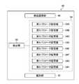
- FIG. 7is a block diagram illustrating a configuration of the recognition result notifying unit 60 according to the first embodiment.
- the recognition result notifying section 60includes a display notifying section 62.
- the display notification unit 62includes a display 62A.
- the display 62Ais a display device that outputs and displays information such as an image.
- the display notifying unit 62notifies the display 62A that the lesion has been detected.
- the display 62Ais common to the display unit 18.
- the notification control unit 58determines that the lesion has been detected such that the notification power is relatively higher when the inspection process is a removal process than when it is an insertion process.
- the display notification unit 62is notified.
- FIG. 8is a diagram showing an example of notifying that a lesion has been detected from an image by displaying characters.
- the notification control unit 58controls the display notification unit 62 to notify that the lesion L has been detected from the image G. Informing by the display of characters.
- F81 shown in FIG. 8indicates a case where the inspection process of the insertion portion 12A is an insertion process. In the case of F81, the character 100A of the first size is displayed on the display 62A.
- F82 shown in FIG. 8indicates a case where the process of moving the insertion portion 12A is a removal process. In the case of F82, a character 100B of a second size larger than the first size is displayed on the display 62A.
- the notification power in the removal processis relatively higher than that in the insertion process by varying the size of the characters.
- the differenceis not limited to the size of the character, and the color of the character may be changed.
- a character with a relatively high color or a character with a relatively low saturationhas a relatively higher notification power than a character with a relatively low color.
- characters having a reddish huehave relatively higher informing power than characters having a blued hue.
- the notification powermay be changed according to the inspection process, without being limited to the example of changing the size or color of the character.
- Various embodimentsare possible.
- FIG. 9is a diagram showing an example of notifying that a lesion has been detected from an image by displaying icons.
- the notification control unit 58controls the display notification unit 62 to notify that the lesion L has been detected from the image G.
- the iconis displayed.
- F91 shown in FIG. 9indicates a case where the inspection process is an insertion process.
- the icon 102A of the first sizeis displayed on the display 62A.
- F92 shown in FIG. 9indicates a case where the inspection process is a removal process.
- an icon 102B of a second size larger than the first sizeis displayed on the display 62A.
- FIG. 10is a diagram showing an example in which a background is displayed to notify that a lesion has been detected from an image.
- the notification control unit 58controls the display notification unit 62 to notify that the lesion L has been detected from the image G. This is indicated by the background display.
- the backgroundis an area other than the image G in the display range of the display 62A. Normally, a black background is displayed.
- FF101 shown in FIG. 10indicates a case where the inspection process is an insertion process.
- a background 104A of a first background color different from blackis displayed on the display 62A.
- F102 shown in FIG. 10indicates a case where the inspection process is a removal process.
- a background 104B of a second background color higher in brightness than the first background coloris displayed on the display 62A.
- the brightness of the background colorBy making the brightness of the background color different as described above, it is possible to make the notification power in the removal process relatively higher than in the insertion process.
- the differenceis not limited to the brightness of the background color, and the saturation or hue of the background color may be changed.
- the background color having a relatively high saturationhas a relatively high notification power.
- the background color of a reddish huehas a relatively higher notification power than the background color of a bluedish hue.
- FIG. 11is a diagram showing an example of notifying that a lesion has been detected from an image by displaying a frame.
- the notification control unit 58controls the display notification unit 62 to notify that the lesion L has been detected from the image G.
- the notificationis made by displaying a frame including the lesion L.
- F111 shown in FIG. 11indicates a case where the inspection process is an insertion process.
- the frame 106A of the first sizeis displayed on the display 62A together with the image G.
- the image G displayed on the display 62Ais displayed in the frame 106A.
- the notification control unit 58may display, in the frame 106A, the image immediately before the lesion L is detected, instead of the image G displayed on the display 62A.
- FF112 shown in FIG. 11indicates a case where the inspection process is a removal process.
- a frame 106B of a second size larger than the first sizeis displayed on the display 62A together with the image G.
- the image displayed in the frame 106Bmay be the same image as F111.
- the notification power in the removal processcan be made relatively higher than in the insertion process.
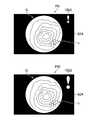
- FIG. 12is a diagram showing an example of notifying that a lesion has been detected from an image in a different display mode.
- the notification control unit 58controls the display notification unit 62 to notify that the lesion L has been detected from the image G.
- the notificationis made in a different display manner according to the process determined by the insertion / removal determination unit 68.
- F121 shown in FIG. 12indicates a case where the inspection process is an insertion process.
- the icon 102A of the first sizeis displayed on the display 62A. Icon 102A may be hidden.
- F122 shown in FIG. 12indicates a case where the inspection process is a removal process.
- the figure 108 indicating the range of the lesion Lis superimposed on the image G at the position of the lesion L on the display 62A.
- the notification power in the removal processis relatively higher than in the insertion process. can do.
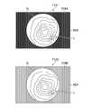
- FIG. 13is a diagram illustrating an example of notifying that a lesion has been detected from an image at different display times.
- the notification control unit 58controls the display notification unit 62 to notify that the lesion L has been detected from the image G. Alerts at different display times.
- F131 and F132 shown in FIG. 13show a case where the inspection process is an insertion process. In the case of F131, a figure 108 indicating the range of the lesion L is superimposed on the image G at the position of the lesion L on the display 62A.
- F132indicates a case where a predetermined time has elapsed from F131 and the insertion section 12A has further moved in the insertion direction.
- the lesion Lis not detected from the image G, and the figure 108 is not displayed. That is, when the examination process is the insertion process, the notification control unit 58 superimposes and displays the graphic 108 indicating the range of the lesion on the image G only at the time of detecting the lesion L.
- F133 and F134 shown in FIG. 13show a case where the inspection process is a removal process.
- the figure 108 indicating the range of the lesion Lis superimposed on the image G at the position of the lesion L on the display 62A.
- F134shows a case where a certain time has elapsed from F133, and the insertion portion 12A has further moved in the withdrawal direction.
- the lesion Lis not detected from the image G, but the figure 108 displayed in F133 is continuously displayed at the same position. That is, when the inspection process is the removal process, the notification control unit 58 superimposes the graphic 108 indicating the range of the lesion at the lesion position on the image G at the time of detection of the lesion L and for a certain period after the detection.
- the notification power in the removal processcan be made relatively higher than in the insertion process.
- the display unit 18 and the display 62Aare common, but the image G may be displayed on the display unit 18 and the notification of the result of the defect detection may be displayed on the display 62A.
- FIG. 14is a block diagram illustrating a configuration of a recognition result notifying unit 60 according to the second embodiment.
- the recognition result notifying section 60includes a sound notifying section 64.
- the sound notification unit 64includes a buzzer 64A.
- the buzzer 64Ais a sound generating device that generates a notification sound, and for example, a piezoelectric buzzer having a piezoelectric element is applied.
- the sound notification unit 64notifies the buzzer 64A of the notification that the lesion has been detected.
- the buzzer 64Ais provided in the processor device 16.
- the notification control unit 58determines that the lesion has been detected such that the notification power is relatively higher when the inspection process is a removal process than when it is an insertion process.
- the sound notification unit 64is notified. That is, the notification control unit 58 causes the sound notification unit 64 to output at the first volume (sound volume) in the insertion step, and outputs the sound notification unit 64 with the second volume higher than the first volume in the removal step. Let it.
- the notification power in the removal processis relatively higher than that in the insertion process.
- the differenceis not limited to the volume, and the length of the sound may be changed. In this case, a relatively long sound has a relatively higher notification power than a relatively short sound.
- FIG. 15is a block diagram illustrating a configuration of a recognition result notifying unit 60 according to the third embodiment.
- the recognition result notifying section 60includes a lighting notifying section 66.
- the lighting notification unit 66includes a lamp 66A.
- the lamp 66Ais a light source that generates notification light, and for example, a light emitting diode is applied.
- the lighting notifying unit 66notifies that the lesion has been detected by lighting the lamp 66A.
- the lamp 66Ais provided in the processor device 16.
- the notification control unit 58determines that the lesion has been detected such that the notification power is relatively higher when the inspection process is a removal process than when it is an insertion process.
- the lighting notification unit 66is notified. That is, the notification control unit 58 causes the lighting notification unit 66 to emit light at the first light amount (light intensity) in the insertion step, and outputs the second light amount larger than the first light amount to the lighting notification unit 66 in the removal step. Let it.
- the notification power in the removal processis relatively higher than that in the insertion process.
- the differenceis not limited to the light amount, and the color of the light may be changed.
- the notification poweris relatively higher in the lighting in the red hue than in the lighting in the blue hue.
- the lighting timemay be different. For example, a continuous lighting state in which the lighting time is relatively long has a higher notification power than a blinking state in which the lighting time is relatively short.
- FIG. 16is a block diagram illustrating a configuration of a recognition result notifying unit 60 according to the fourth embodiment.
- the recognition result notifying unit 60includes a display notifying unit 62 and a sound notifying unit 64.
- the notification control unit 58determines that the lesion has been detected such that the notification power is relatively higher when the inspection process is a removal process than when it is an insertion process.
- the recognition result notifying unit 60is notified. That is, in the insertion step, the notification control unit 58 causes the display notification unit 62 to superimpose the figure 108 indicating the range of the lesion L on the image G at the position of the lesion L on the display 62A, similarly to F112 in FIG.
- the notification control unit 58causes the display notification unit 62 to superimpose a graphic 108 indicating the range of the lesion L on the image G at the position of the lesion L on the display 62A in the same manner as in the insertion process, and perform a sound notification unit. 64 is made to output sound.
- the same displayis made on the display 62A and the presence or absence of the sound output of the buzzer 64A is made different, so that the informing power in the case of the removal process is more than that in the case of the insertion process. To be high.
- the configuration of the recognition result notifying unit 60 according to the fifth embodimentis the same as the configuration of the recognition result notifying unit 60 according to the fourth embodiment.
- the notification control unit 58determines that the lesion has been detected such that the notification power is relatively higher when the inspection process is a removal process than when it is an insertion process.
- the recognition result notifying unit 60is notified. That is, in the insertion step, the notification control unit 58 causes the sound notification unit 64 to output a sound.
- the notification control unit 58causes the sound notification unit 64 to output a sound, and causes the display notification unit 62 to display the icon 102B on the display 62A as in the case of F92 in FIG.
- the same soundis output by the buzzer 64A and the display on the display 62A is made different, so that the notification power in the removal process is relatively higher than that in the insertion process. ing.
- FIG. 17is a block diagram illustrating a configuration of a recognition result notifying unit 60 according to the sixth embodiment.
- the recognition result notifying unit 60includes a display notifying unit 62, a sound notifying unit 64, and a lighting notifying unit 66.
- the notification control unit 58determines that the lesion has been detected such that, when the inspection process is the removal process, the notification power is relatively higher than when the inspection process is the insertion process.
- the recognition result notifying unit 60is notified. That is, in the insertion step, the notification control unit 58 causes the lighting notification unit 66 to turn on the lamp 66A.
- the notification control unit 58causes the lighting notification unit 66 to turn on the lamp 66A, and the display notification unit 62 displays a figure 108 indicating the range of the lesion L on the image G at the position of the lesion L on the display 62A.
- the sound notifying section 64outputs the sound of the buzzer 64A.
- the same lightingis performed by the lamp 66A and the display of the display 62A and the output of the sound of the buzzer 64A are made different, so that the informing power in the case of the removal process is larger than in the case of the insertion process. Is relatively high.
- the notification control unit 58notifies the N by one of the display notification unit 62, the sound notification unit 64, and the lighting notification unit 66 in the insertion step.
- the notificationmay be performed by at least (N + 1) of the display notification unit 62, the sound notification unit 64, and the lighting notification unit 66.
- the notification by the display notification unit 62may be performed by using any of notification by displaying characters, notification by displaying icons, notification by changing the background color, notification by displaying a frame, and notification by displaying a graphic indicating the range of a lesion. Good.
- the notification by the sound notification unit 64is notification by a notification sound of the buzzer 64A.
- the notification by the lighting notification unit 66is notification by lighting of the lamp 66A.
- the notification power in the removal processcan be relatively higher than in the insertion process.
- the notification methodmay be any method as long as the notification power in the removal step is relatively higher than that in the insertion step, and the doctor can be expected to be more alert.
- the medical image analysis processing unitdetects a region of interest, which is a region of interest, based on the feature amounts of pixels of the medical image (endoscope image),
- the medical image analysis result acquisition unitis a medical image processing device that acquires an analysis result of the medical image analysis processing unit.
- the medical image analysis processing unitdetects the presence or absence of a target to be noted based on the feature amount of the pixel of the medical image
- the medical image analysis result acquisition unitis a medical image processing device that acquires an analysis result of the medical image analysis processing unit.
- the medical image analysis result acquisition unitAcquired from a recording device that records the analysis results of medical images,
- the analysis resultis a medical image processing apparatus in which either or both of a region of interest, which is a region of interest included in the medical image, and a target of interest, which are notable, are included.
- a medical image processing apparatuswherein a medical image is a normal light image obtained by irradiating white band light or light of a plurality of wavelength bands as white band light.
- a medical imageis an image obtained by irradiating light in a specific wavelength band,
- the medical image processing apparatushas a specific wavelength band narrower than the white wavelength band.
- the specific wavelength bandis a medical image processing device in a visible blue or green band.
- the specific wavelength bandincludes a wavelength band of 390 nm to 450 nm or 530 nm to 550 nm, and the light of the specific wavelength band has a peak wavelength in the wavelength band of 390 nm to 450 nm or 530 nm to 550 nm.
- Image processing deviceincludes a wavelength band of 390 nm to 450 nm or 530 nm to 550 nm, and the light of the specific wavelength band has a peak wavelength in the wavelength band of 390 nm to 450 nm or 530 nm to 550 nm.
- the medical image processing devicehas a specific wavelength band in a visible red band.
- the specific wavelength bandincludes a wavelength band of 585 nm to 615 nm or 610 nm to 730 nm, and the light of the specific wavelength band has a peak wavelength in the wavelength band of 585 nm to 615 nm or 610 nm to 730 nm.
- Image processing deviceincludes a wavelength band of 585 nm to 615 nm or 610 nm to 730 nm, and the light of the specific wavelength band has a peak wavelength in the wavelength band of 585 nm to 615 nm or 610 nm to 730 nm.
- the specific wavelength bandincludes a wavelength band having a different extinction coefficient between oxyhemoglobin and reduced hemoglobin, and light of a specific wavelength band has a peak wavelength in a wavelength band having a different extinction coefficient between oxyhemoglobin and reduced hemoglobin.
- the specific wavelength bandincludes a wavelength band of 400 ⁇ 10 nm, 440 ⁇ 10 nm, 470 ⁇ 10 nm, or a wavelength band of 600 nm or more and 750 nm or less, and light of the specific wavelength band is 400 ⁇ 10 nm, 440 ⁇ 10 nm, 470 ⁇ A medical image processing apparatus having a peak wavelength in a wavelength band of 10 nm or 600 nm to 750 nm.
- a medical imageis an in-vivo image of a living body
- the in-vivo imageis a medical image processing apparatus having information on fluorescence emitted by a fluorescent substance in a living body.
- a medical imageis an in-vivo image of a living body,
- the specific wavelength bandis a wavelength band of infrared light in the medical image processing apparatus.
- the specific wavelength bandincludes a wavelength band of 790 nm to 820 nm or 905 nm to 970 nm, and the light of the specific wavelength band has a peak wavelength in a wavelength band of 790 nm to 820 nm or 905 nm to 970 nm. Processing equipment.
- the medical image acquisition unitis configured to acquire a special light image having information of a specific wavelength band based on a normal light image obtained by irradiating light in a plurality of wavelength bands as light in a white band or light in a white band.
- An optical image acquisition unit, The medical imageis a medical image processing device that is a special light image.
- a medical image processing apparatusin which a signal in a specific wavelength band is obtained by a calculation based on RGB (Red Green Blue) or CMY (Cyan, Magenta, Yellow) color information included in a normal light image.
- RGBRed Green Blue
- CMYCyan, Magenta, Yellow
- Appendix 18Light in the white band, or a normal light image obtained by irradiating light in a plurality of wavelength bands as light in the white band, and a calculation based on at least one of the special light image obtained by irradiating light in a specific wavelength band, A feature image generating unit that generates a feature image; A medical image processing device in which the medical image is a feature image.
- a diagnosis support devicecomprising the medical image processing device according to any one of supplementary notes 1 to 18.
- a hardware structure of a processing unitthat executes various processes of the image recognition unit 46, the notification control unit 58, and the insertion / removal determination unit 68 is as follows.
- the various processorsinclude a CPU (Central Processing Unit), which is a general-purpose processor that executes software (programs) and functions as various processing units, a GPU (Graphics Processing Unit), which is a processor specialized in image processing, Dedicated to execute specific processing such as Programmable Logic Device (PLD), which is a processor whose circuit configuration can be changed after manufacturing such as FPGA (Field Programmable Gate Array) and ASIC (Application Specific Integrated Circuit).
- a dedicated electric circuitwhich is a processor having a designed circuit configuration is included.
- One processing unitmay be configured by one of these various processors, or may be configured by two or more processors of the same type or different types (for example, a plurality of FPGAs, a combination of a CPU and an FPGA, or a combination of a CPU and a CPU). (Combination of GPUs). Further, a plurality of processing units may be configured by one processor. As an example of configuring a plurality of processing units with one processor, first, as represented by a computer such as a server and a client, one processor is configured by a combination of one or more CPUs and software. There is a form in which a processor functions as a plurality of processing units.
- SoCsystem-on-chip
- a form using a processor that realizes the functions of the entire system including a plurality of processing units with one integrated circuit (IC) chipis used.
- ICintegrated circuit
- the various processing unitsare configured using one or more various processors as a hardware structure.
- circuitryin which circuit elements such as semiconductor elements are combined.
- Information control section 60... Recognition result informing section 62 ... Display informing section 62A ... Display 64 ... Sound informing section 64A ... Buzzer 66 ... Lighting informing section 66A ... Lamp 68 ... Insertion / extraction discrimination section 70 ... Display control section 72 ...
- Storage control section 74... storage unit 100A ... character 100B ... character 102A ... icon 102B ... icon 106A ... frame 106B ... frame 108 ... figure G ... image L ... lesion L1 ... light L11 ... excitation light L12 ... laser light L2 ... light S1 to S7 ... recognition result Of each notification method
Landscapes
- Health & Medical Sciences (AREA)
- Life Sciences & Earth Sciences (AREA)
- Surgery (AREA)
- Physics & Mathematics (AREA)
- Engineering & Computer Science (AREA)
- Biomedical Technology (AREA)
- Animal Behavior & Ethology (AREA)
- Radiology & Medical Imaging (AREA)
- Optics & Photonics (AREA)
- Nuclear Medicine, Radiotherapy & Molecular Imaging (AREA)
- Biophysics (AREA)
- Heart & Thoracic Surgery (AREA)
- Medical Informatics (AREA)
- Molecular Biology (AREA)
- Pathology (AREA)
- General Health & Medical Sciences (AREA)
- Public Health (AREA)
- Veterinary Medicine (AREA)
- General Physics & Mathematics (AREA)
- Electromagnetism (AREA)
- Signal Processing (AREA)
- Theoretical Computer Science (AREA)
- Endoscopes (AREA)
Abstract
Description
Translated fromJapanese本発明は内視鏡システムに係り、特に内視鏡画像から注目領域を検出して報知する技術に関する。The present invention relates to an endoscope system, and more particularly, to a technique for detecting and notifying a region of interest from an endoscope image.
内視鏡検査は基本的に、臓器に付着した汚れを洗い流しながらスコープを奥まで挿入し、その後に、臓器の中を観察しながら抜去する。このように、挿入時と抜去時とで医師の作業が異なることに応じて、挿入時と抜去時とで動作を異ならせた内視鏡装置が知られている。は Endoscopy basically involves inserting the scope all the way down while washing off dirt attached to the organ, and then removing it while observing inside the organ. As described above, there is known an endoscope apparatus in which the operation is different between the time of insertion and the time of removal in response to the fact that the operation of the doctor differs between the time of insertion and the time of removal.
例えば、特許文献1には、挿入部の移動方向が挿入方向である場合に、抜去方向である場合よりも撮像部のフレームレートを高くする技術が開示されている。この技術によれば、挿入時に挿入部の先端の揺動や移動による画像の頻繁な変動が生じても、滑らかな動画として画像表示部に表示することができ、スムーズな挿入作業を行うことができる。For example,
内視鏡検査中の医師を補助する技術として、内視鏡画像から病変等の注目領域を検出し、報知する技術が知られている。しかしながら、内視鏡検査中のタイミングによっては、注目領域の検出結果を報知することが、医師の操作を阻害する可能性がある。(4) As a technique for assisting a doctor during an endoscopy, a technique for detecting a region of interest such as a lesion from an endoscopic image and notifying the same is known. However, depending on the timing during the endoscopy, the notification of the detection result of the attention area may hinder the operation of the doctor.
例えば、挿入部の抜去時は、当然病変を見つける必要があるので、検出結果の報知による補助は有用である。一方、挿入は技術的に難しく、集中力が要求されるため、挿入時は検出結果の報知が医師の操作の妨げになる可能性がある。For example, when removing the insertion part, it is necessary to find the lesion, so assistance by reporting the detection result is useful. On the other hand, since insertion is technically difficult and requires concentration, there is a possibility that the notification of the detection result may hinder the operation of the doctor during insertion.
本発明はこのような事情に鑑みてなされたもので、注目領域の検出結果を適切に報知する内視鏡システムを提供することを目的とする。The present invention has been made in view of such circumstances, and has as its object to provide an endoscope system that appropriately notifies a detection result of an attention area.
上記目的を達成するために内視鏡システムの一の態様は、患者の管腔内を検査する内視鏡システムであって、管腔内に挿入される挿入部と、管腔内を撮影して内視鏡画像を取得するカメラと、内視鏡画像から注目領域を検出する注目領域検出部と、注目領域の検出結果の報知を行う検出結果報知部と、検査の工程が挿入部を管腔内の折り返し地点まで挿入させる挿入工程及び挿入部を折り返し地点から抜去させる抜去工程のいずれの工程であるかを判別する挿抜判別部と、挿抜判別部が判別した工程に応じて検出結果報知部に報知を行わせる報知制御部と、を備える内視鏡システムである。One mode of the endoscope system to achieve the above object is an endoscope system for examining the inside of a lumen of a patient, and an insertion portion to be inserted into the lumen and taking an image of the inside of the lumen. A camera that obtains an endoscope image through the camera, an attention area detection unit that detects an attention area from the endoscope image, a detection result notification unit that notifies the detection result of the attention area, and an inspection process that controls the insertion unit. An insertion / extraction discriminator for discriminating which of an insertion process for inserting the insertion portion up to the turning point in the cavity and a removal process for removing the insertion portion from the turning point, and a detection result notifying portion according to the process discriminated by the insertion / extraction discriminating portion And a notification control unit for causing the notification to be performed.
本態様によれば、検査の工程が挿入工程及び抜去工程のいずれの工程であるかを判別し、判別した工程に応じて注目領域の検出結果の報知を行わせるようにしたので、注目領域の検出結果を適切に報知することができる。According to this aspect, it is determined whether the inspection step is the insertion step or the removal step, and the detection result of the attention area is notified according to the determined step. The detection result can be appropriately reported.
検出結果報知部は、注目領域が検出された旨をディスプレイの表示で報知する表示報知部を備え、報知制御部は、挿入工程では第1の大きさの文字を表示させ、抜去工程では第1の大きさより大きい第2の大きさの文字を表示させることが好ましい。これにより、挿入工程よりも抜去工程において相対的に高い報知力で報知することができる。The detection result notifying section includes a display notifying section for notifying that the attention area has been detected on a display, and the notifying control section causes the first size character to be displayed in the inserting step and the first notifying step in the removing step. It is preferable to display a character of a second size larger than the size of. Thereby, it is possible to notify with a relatively high notification power in the removal step than in the insertion step.
検出結果報知部は、注目領域が検出された旨をディスプレイの表示で報知する表示報知部を備え、報知制御部は、挿入工程では第1の大きさのアイコンを表示させ、抜去工程では第1の大きさより大きい第2の大きさのアイコンを表示させることが好ましい。これにより、挿入工程よりも抜去工程において相対的に高い報知力で報知することができる。The detection result notifying unit includes a display notifying unit for notifying that the attention area has been detected on a display, and the notifying control unit displays an icon of a first size in the inserting step, and displays the first size icon in the removing step. It is preferable to display an icon of a second size larger than the size of. Thereby, it is possible to notify with a relatively high notification power in the removal step than in the insertion step.
検出結果報知部は、注目領域が検出された旨をディスプレイの表示で報知する表示報知部を備え、報知制御部は、挿入工程では第1の背景色の背景を表示させ、抜去工程では第1の背景色より明度の高い第2の背景色の背景を表示させることが好ましい。これにより、挿入工程よりも抜去工程において相対的に高い報知力で報知することができる。The detection result notifying unit includes a display notifying unit for notifying that the attention area has been detected on a display, and the notifying control unit displays the background of the first background color in the inserting step, and displays the first background color in the removing step. It is preferable to display a background of a second background color having a higher brightness than the background color of. Thereby, it is possible to notify with a relatively high notification power in the removal step than in the insertion step.
検出結果報知部は、注目領域が検出された旨をディスプレイの表示で報知する表示報知部を備え、報知制御部は、挿入工程では注目領域を含む第1の大きさのフレームを内視鏡画像と共に表示させ、抜去工程では注目領域を含む第1の大きさより大きい第2の大きさのフレームを内視鏡画像と共に表示させることが好ましい。これにより、挿入工程よりも抜去工程において相対的に高い報知力で報知することができる。The detection result notifying unit includes a display notifying unit for notifying that the attention area has been detected on a display, and the notification control unit transmits the first size frame including the attention area to the endoscope image in the inserting step. It is preferable that a frame having a second size larger than the first size including the region of interest is displayed together with the endoscope image in the removal step. Thereby, it is possible to notify with a relatively high notification power in the removal step than in the insertion step.
検出結果報知部は、注目領域が検出された旨をディスプレイの表示で報知する表示報知部を備え、報知制御部は、挿入工程では非表示又はアイコンを表示させ、抜去工程では注目領域の位置に注目領域の範囲を示す図形を内視鏡画像に重畳表示させることが好ましい。これにより、挿入工程よりも抜去工程において相対的に高い報知力で報知することができる。The detection result notifying unit includes a display notifying unit for notifying that the attention area has been detected on the display of the display, and the notification control unit causes the insertion step to hide or display the icon, and to remove the icon at the position of the attention area in the removal step. It is preferable to superimpose and display a figure indicating the range of the attention area on the endoscope image. Thereby, it is possible to notify with a relatively high notification power in the removal step than in the insertion step.
検出結果報知部は、注目領域が検出された旨をディスプレイの表示で報知する表示報知部を備え、報知制御部は、挿入工程では注目領域の検出時のみ注目領域の位置に注目領域の範囲を示す図形を内視鏡画像に重畳表示させ、抜去工程では注目領域の検出時及び検出後の一定時間において注目領域の位置に注目領域の範囲を示す図形を内視鏡画像に重畳表示させることが好ましい。これにより、挿入工程よりも抜去工程において相対的に高い報知力で報知することができる。The detection result notifying unit includes a display notifying unit for notifying that the attention area has been detected on the display of the display, and the notification control unit sets the range of the attention area to the position of the attention area only when the attention area is detected in the insertion step. In the removal process, the figure indicating the range of the attention area is superimposed on the endoscope image at the position of the attention area at the time of detection of the attention area and at a certain time after the detection. preferable. Thereby, it is possible to notify with a relatively high notification power in the removal step than in the insertion step.
検出結果報知部は、注目領域が検出された旨を音の出力で報知する音報知部を備え、報知制御部は、挿入工程では第1の音量で出力させ、抜去工程では第1の音量より大きい第2の音量で出力させることが好ましい。これにより、挿入工程よりも抜去工程において相対的に高い報知力で報知することができる。The detection result notifying unit includes a sound notifying unit for notifying that the attention area has been detected by outputting a sound, and the notifying control unit causes the first sound volume to be output in the inserting step and the first sound volume to be output in the removing step. It is preferable to output at a large second volume. Thereby, it is possible to notify with a relatively high notification power in the removal step than in the insertion step.
検出結果報知部は、注目領域が検出された旨をランプの点灯で報知する点灯報知部を備え、報知制御部は、挿入工程では第1の光量で点灯させ、抜去工程では第1の光量より大きい第2の光量で点灯させることが好ましい。これにより、挿入工程よりも抜去工程において相対的に高い報知力で報知することができる。The detection result notifying unit includes a lighting notifying unit for notifying that the attention area has been detected by turning on the lamp, and the notifying control unit turns on the light at the first light amount in the inserting step and detects the light amount in the removing step from the first light amount. It is preferable to light up with a large second light amount. Thereby, it is possible to notify with a relatively high notification power in the removal step than in the insertion step.
検出結果報知部は、ディスプレイの表示で報知する表示報知部と、音の出力で報知する音報知部と、を備え、報知制御部は、挿入工程では表示報知部に注目領域の位置に注目領域の範囲を示す図形を内視鏡画像に重畳表示させ、抜去工程では表示報知部に注目領域の位置に注目領域の範囲を示す図形を内視鏡画像に重畳表示させ、かつ音報知部に音を出力させることが好ましい。これにより、挿入工程よりも抜去工程において相対的に高い報知力で報知することができる。The detection result notifying unit includes a display notifying unit for notifying by a display on the display, and a sound notifying unit for notifying by a sound output. In the removal process, a graphic indicating the range of the attention area is superimposed and displayed on the endoscope image at the position of the attention area, and the sound notification section displays a sound indicating the range of the attention area. Is preferably output. Thereby, it is possible to notify with a relatively high notification power in the removal step than in the insertion step.
検出結果報知部は、ディスプレイの表示で報知する表示報知部と、音の出力で報知する音報知部と、を備え、報知制御部は、挿入工程では音報知部に音を出力させ、抜去工程では音報知部に音を出力させ、かつ表示報知部にアイコンを表示させることが好ましい。これにより、挿入工程よりも抜去工程において相対的に高い報知力で報知することができる。The detection result notifying section includes a display notifying section for notifying by a display on the display, and a sound notifying section for notifying by outputting sound, and the notifying control section causes the sound notifying section to output sound in the inserting step, and removes the sound. Then, it is preferable to output a sound to the sound notification unit and display an icon on the display notification unit. Thereby, it is possible to notify with a relatively high notification power in the removal step than in the insertion step.
検出結果報知部は、ディスプレイの表示で報知する表示報知部と、音の出力で報知する音報知部と、ランプの点灯で報知する点灯報知部と、を備え、報知制御部は、挿入工程では点灯報知部にランプを点灯させ、抜去工程では点灯報知部にランプを点灯させ、かつ表示報知部に注目領域の位置に注目領域の範囲を示す図形を内視鏡画像に重畳表示させ、かつ音報知部に音を出力させることが好ましい。これにより、挿入工程よりも抜去工程において相対的に高い報知力で報知することができる。The detection result notifying unit includes a display notifying unit notifying by display on the display, a sound notifying unit notifying by sound output, and a lighting notifying unit notifying by lighting of the lamp, and the notifying control unit includes: In the removal process, the lamp is turned on by the lighting notifying unit, the lamp is turned on by the lighting notifying unit, and a graphic indicating the range of the attention area is superimposed on the endoscope image at the position of the attention area on the display notification unit, and the sound is sounded. It is preferable to output a sound to the notification unit. Thereby, it is possible to notify with a relatively high notification power in the removal step than in the insertion step.
検出結果報知部は、ディスプレイの表示で報知する表示報知部と、音の出力で報知する音報知部と、ランプの点灯で報知する点灯報知部と、を備え、Nを0~2のうちのいずれかの整数とすると、報知制御部は、挿入工程では表示報知部、音報知部、及び点灯報知部のうちのいずれかN個により報知を行わせ、抜去工程では表示報知部、音報知部、及び点灯報知部のうちの少なくとも(N+1)個により報知を行わせることが好ましい。これにより、挿入工程よりも抜去工程において相対的に高い報知力で報知することができる。The detection result notifying unit includes a display notifying unit for notifying by display on the display, a sound notifying unit for notifying by sound output, and a lighting notifying unit for notifying by lighting of the lamp. Assuming any integer, the notification control unit causes the display notification unit, the sound notification unit, and the lighting notification unit to perform notification in any of the N units in the insertion process, and the display notification unit and the sound notification unit in the removal process. , And at least (N + 1) of the lighting notification units. Thereby, it is possible to notify with a relatively high notification power in the removal step than in the insertion step.
本発明によれば、注目領域の検出結果を適切に報知することができる。According to the present invention, the detection result of the attention area can be appropriately reported.
以下、添付図面に従って本発明の好ましい実施形態について詳説する。Hereinafter, preferred embodiments of the present invention will be described in detail with reference to the accompanying drawings.
ここでは、被験者の肛門から挿入され、直腸及び大腸等の管腔内を検査(観察)するために用いられる下部内視鏡に本発明を適用する場合について説明する。なお、患者の口又は鼻から挿入され、食道及び胃等の管腔内を観察するために用いられる上部内視鏡に本発明を適用することも可能である。Here, a case will be described in which the present invention is applied to a lower endoscope which is inserted from the anus of a subject and used for inspecting (observing) the inside of a lumen such as the rectum and the large intestine. The present invention can be applied to an upper endoscope which is inserted from a mouth or a nose of a patient and used for observing a lumen such as an esophagus and a stomach.
<内視鏡システムの構成>
図1は、内視鏡システム10を示す外観図である。図1に示すように、内視鏡システム10は、内視鏡12、光源装置14、プロセッサ装置16、表示部18、及び入力部20を備えている。<Configuration of endoscope system>
FIG. 1 is an external view showing an
内視鏡12は、光源装置14と光学的に接続される。また、内視鏡12は、プロセッサ装置16と電気的に接続される。The
内視鏡12は、被験者の管腔内に挿入される挿入部12A、挿入部12Aの基端部分に設けられた操作部12B、挿入部12Aの先端側に設けられた湾曲部12C及び先端部12Dを有している。The
操作部12Bには、アングルノブ12E及びモード切替スイッチ13が設けられている。The
アングルノブ12Eを操作することにより、湾曲部12Cが湾曲動作する。この湾曲動作によって先端部12Dが所望の方向に向けられる。湾 曲 By operating the
モード切替スイッチ13は、観察モードの切り替え操作に用いられる。内視鏡システム10は、照射光の波長パターンがそれぞれ異なる複数の観察モードを有している。医師(術者)は、モード切替スイッチ13を操作することにより、所望の観察モードに設定することができる。内視鏡システム10は、波長パターンと画像処理との組み合わせによって、設定された観察モードに応じた画像を生成して表示部18に表示する。The
また、操作部12Bには、不図示の取得指示入力部が設けられている。取得指示入力部は、医師が静止画の取得指示を入力するためのインターフェースである。取得指示入力部は、静止画の取得指示を受け付ける。取得指示入力部において受け付けた静止画の取得指示は、プロセッサ装置16に入力される。(4) The
プロセッサ装置16は、表示部18及び入力部20と電気的に接続される。表示部18は、被観察領域の画像及び被観察領域の画像に関連する情報等を出力表示する表示デバイスである。入力部20は、内視鏡システム10の機能設定及び各種指示等の入力操作を受け付けるユーザインターフェースとして機能する。The
内視鏡システム10における検査の工程は、挿入工程及び抜去工程からなる。挿入工程とは内視鏡12の挿入部12Aの先端部12Dを患者の管腔内の挿入開始地点から折り返し地点まで挿入させる工程であり、抜去工程とは先端部12Dを患者の管腔内の折り返し地点から挿入開始地点まで抜去させる工程である。検 査 The inspection process in the
なお、挿入開始地点とは、先端部12Dの挿入を開始する管腔の端部である。挿入開始地点は、例えば、下部内視鏡であれば肛門であり、上部内視鏡であれば口又は鼻である。また、折り返し地点とは、先端部12Dが到達する管腔内の最も奥の位置である。折り返し地点において、挿入部12Aのうち管腔内に挿入された部分が最も多くなる。挿入 The insertion start point is the end of the lumen where insertion of the
図2は、内視鏡システム10の内部構成を示すブロック図である。図2に示すように、光源装置14は、第1レーザ光源22A、第2レーザ光源22B、及び光源制御部24を備えている。FIG. 2 is a block diagram showing an internal configuration of the
第1レーザ光源22Aは、中心波長445nmの青色レーザ光源である。第2レーザ光源22Bは、中心波長405nmの紫色レーザ光源である。第1レーザ光源22A及び第2レーザ光源22Bとして、レーザダイオードを用いることができる。第1レーザ光源22A及び第2レーザ光源22Bの発光は、光源制御部24により個別に制御される。第1レーザ光源22Aと第2レーザ光源22Bとの発光強度比は変更自在になっている。The first
また、図2に示すように、内視鏡12は、光ファイバ28A、光ファイバ28B、蛍光体30、拡散部材32、撮像レンズ34、撮像素子36、及びアナログデジタル変換部38を備えている。As shown in FIG. 2, the
第1レーザ光源22A、第2レーザ光源22B、光ファイバ28A、光ファイバ28B、蛍光体30、及び拡散部材32によって、照射部が構成される。The first
第1レーザ光源22Aから出射されるレーザ光は、光ファイバ28Aによって、内視鏡12の先端部12Dに配置された蛍光体30に照射される。蛍光体30は、第1レーザ光源22Aからの青色レーザ光の一部を吸収して緑色~黄色に励起発光する複数種の蛍光体を含んで構成される。これにより、蛍光体30から出射する光は、第1レーザ光源22Aからの青色レーザ光を励起光とする緑色~黄色の励起光L11と、蛍光体30に吸収されずに透過した青色のレーザ光L12とが合わされて、白色(疑似白色)の光L1となる。(4) The laser light emitted from the first
なお、ここで言う白色光とは、厳密に可視光の全ての波長成分を含むものに限らない。例えば、R(Red)、G(Green )、B(Blue)等、特定の波長帯域の光を含むものであればよく、緑色から赤色にかけての波長成分を含む光、又は青色から緑色にかけての波長成分を含む光等も広義に含むものとする。白色 Incidentally, the white light mentioned here is not limited to a light that strictly includes all wavelength components of visible light. For example, light containing a specific wavelength band, such as R (Red), G (Green), and B (Blue), may be used. Light containing a wavelength component from green to red, or a wavelength from blue to green. Light including components is also included in a broad sense.
一方、第2レーザ光源22Bから出射されるレーザ光は、光ファイバ28Bによって、内視鏡12の先端部12Dに配置された拡散部材32に照射される。拡散部材32は、透光性を有する樹脂材料等を用いることができる。拡散部材32から出射する光は、照射領域内において光量が均一化された狭帯域波長の光L2となる。On the other hand, the laser light emitted from the second
図3は、光L1及び光L2の強度分布を示すグラフである。光源制御部24は、第1レーザ光源22Aと第2レーザ光源22Bとの光量比を変更する。これにより、光L1と光L2との光量比が変更され、光L1と光L2との合成光である照射光L0の波長パターンが変更される。したがって、観察モードに応じて異なる波長パターンの照射光L0を照射することができる。FIG. 3 is a graph showing the intensity distribution of light L1 and light L2. The light
図2の説明に戻り、撮像レンズ34、撮像素子36、及びアナログデジタル変換部38によって、撮影部(カメラ)が構成される。撮影部は、内視鏡12の先端部12Dに配置される。2, returning to the description of FIG. 2, the
撮像レンズ34は、入射した光を撮像素子36に結像させる。撮像素子36は、受光した光に応じたアナログ信号を生成する。撮像素子36としては、CCD(Charge Coupled Device)型イメージセンサ、又はCMOS(Complementary Metal Oxide Semiconductor)型イメージセンサが用いられる。撮像素子36から出力されるアナログ信号は、アナログデジタル変換部38によりデジタル信号に変換され、プロセッサ装置16に入力される。(4) The imaging lens forms an image of the incident light on the imaging device. The
また、図2に示すように、プロセッサ装置16は、撮影制御部40、画像処理部42、画像取得部44、画像認識部46、報知制御部58、認識結果報知部60、挿抜判別部68、表示制御部70、記憶制御部72、及び記憶部74を備えている。Further, as shown in FIG. 2, the
撮影制御部40は、光源装置14の光源制御部24、内視鏡12の撮像素子36及びアナログデジタル変換部38、プロセッサ装置16の画像処理部42を制御することで、内視鏡システム10による動画及び静止画の撮影を統括制御する。The
画像処理部42は、内視鏡12のアナログデジタル変換部38から入力されたデジタル信号に画像処理を施し、内視鏡画像を示す画像データ(以下、画像と表記する)を生成する。画像処理部42は、撮影時の照射光の波長パターンに応じた画像処理を施す。The
画像取得部44は、画像処理部42が生成した画像を取得する。画像取得部44が取得する画像は、1枚の画像でもよいし、複数の画像でもよい。画像取得部44は、被験者の管腔内を一定のフレームレートで時系列的に撮影した動画を連続した多数の画像(静止画)として扱ってもよい。なお、画像取得部44は、入力部20から入力された画像、又は記憶部74に記憶された画像を取得してもよい。また、不図示のネットワークに接続されたサーバ等の外部装置から画像を取得してもよい。The
画像認識部46は、画像取得部44が取得した画像を認識する。図4は、画像認識部46の構成を示すブロック図である。図4に示すように、画像認識部46は、部位認識部48と、検出部50と、鑑別部52とを備えている。The
部位認識部48は、画像取得部44が取得した画像から内視鏡12の先端部12Dが管腔内のどの部位(位置)に存在しているかを認識する。部位認識部48は、管腔内の部位として、直腸、S状結腸、下行結腸、横行結腸、上行結腸、盲腸、回腸、及び空腸等を認識する。The
部位認識部48は、畳み込みニューラルネットワークを用いた深層学習によって学習した学習済みモデルである。部位認識部48は、例えば各部位の粘膜の画像を学習することで、画像から部位を認識することができる。The
なお、部位認識部48は、磁気コイル等を用いた不図示の内視鏡挿入形状観測装置を用いて内視鏡12の湾曲部12Cの形状情報を取得し、形状情報から先端部12Dの位置を推定してもよい。また、部位認識部48は、被検体外部からX線を照射して内視鏡12の湾曲部12Cの形状情報を取得し、形状情報から先端部12Dの位置を推定してもよい。The
検出部50(注目領域検出部の一例)は、入力された画像から注目領域である病変を検出し、病変の画像内位置を認識する。ここでの病変とは、病気が原因のものに限定されず、外観上正常な状態とは異なる状態の領域を含んでいる。病変としては、例えば、ポリープ、癌、大腸憩室、炎症、EMR(Endoscopic Mucosal Resection)瘢痕又はESD(Endoscopic Submucosal Dissection)瘢痕等の治療痕、クリップ箇所、出血点、穿孔、及び血管異型性等が挙げられる。The detection unit 50 (an example of a region of interest detection unit) detects a lesion that is a region of interest from the input image and recognizes the position of the lesion in the image. The lesion here is not limited to the one caused by the disease, but includes a region in a state different from a normal state in appearance. Examples of lesions include treatment scars such as polyps, cancer, colonic diverticulum, inflammation, EMR (Endoscopic Mucosal Resection) scars or ESD (Endoscopic Submucosal Dissection) scars, clipping points, bleeding points, perforations, and vascular atypia. Can be
検出部50は、管腔内の各部位にそれぞれ対応した第1検出部50Aと、第2検出部50Bと、第3検出部50Cと、第4検出部50Dと、第5検出部50Eと、第6検出部50Fと、第7検出部50Gと、第8検出部50Hとを備えている。ここでは、一例として、第1検出部50Aは直腸に、第2検出部50BはS状結腸に、第3検出部50Cは下行結腸に、第4検出部50Dは横行結腸に、第5検出部50Eは上行結腸に、第6検出部50Fは盲腸に、第7検出部50Gは回腸に、第8検出部50Hは空腸に、それぞれ対応している。The
第1検出部50A、第2検出部50B、第3検出部50C、第4検出部50D、第5検出部50E、第6検出部50F、第7検出部50G、及び第8検出部50Hは、それぞれ学習済みモデルである。この複数の学習済みモデルは、それぞれ異なるデータセットを用いて学習したモデルである。詳しくは、複数の学習済みモデルは、それぞれ管腔内の異なる部位を撮影した画像からなるデータセットを用いて学習したモデルである。The first detector 50A, the second detector 50B, the
即ち、第1検出部50Aは直腸の画像からなるデータセット、第2検出部50BはS状結腸の画像からなるデータセット、第3検出部50Cは下行結腸の画像からなるデータセット、第4検出部50Dは横行結腸の画像からなるデータセット、第5検出部50Eは上行結腸の画像からなるデータセット、第6検出部50Fは盲腸の画像からなるデータセット、第7検出部50Gは回腸の画像からなるデータセット、第8検出部50Hは空腸の画像からなるデータセットを用いて学習したモデルである。That is, the first detection unit 50A is a data set including an image of a rectum, the second detection unit 50B is a data set including an image of a sigmoid colon, the
これらの学習済みモデルは、畳み込みニューラルネットワークを用いた深層学習により学習することが望ましい。また、サポートベクタマシンを用いてもよい。こ と が It is desirable to learn these trained models by deep learning using a convolutional neural network. Further, a support vector machine may be used.
検出部50は、第1検出部50A、第2検出部50B、第3検出部50C、第4検出部50D、第5検出部50E、第6検出部50F、第7検出部50G、及び第8検出部50Hの中から、部位認識部48が認識した管腔内の部位に対応した検出部を用いて、病変の検出を行う。The
即ち、管腔内の部位が直腸であれば第1検出部50A、S状結腸であれば第2検出部50B、下行結腸であれば第3検出部50C、横行結腸であれば第4検出部50D、上行結腸であれば第5検出部50E、盲腸であれば第6検出部50F、回腸であれば第7検出部50G、空腸であれば第8検出部50Hによって病変を検出する。That is, the first detecting unit 50A if the site in the lumen is the rectum, the second detecting unit 50B if the sigmoid colon, the third detecting
第1検出部50A~第8検出部50Hは、それぞれ管腔内の部位に応じて学習されているため、部位に応じた適切な検出が可能である。Since the first detection unit 50A to the
鑑別部52は、検出部50が検出した病変について、良性か悪性かを認識する。鑑別部52は、畳み込みニューラルネットワークを用いた深層学習によって学習した学習済みモデルである。検出部50と同様に、鑑別部52を部位毎の識別部として構成してもよい。(4) The
図5は、画像認識部46の構成の他の態様を示すブロック図である。図5に示すように、この態様の画像認識部46は、単一の検出部50と、パラメータ記憶部54とを備えている。また、パラメータ記憶部54は、管腔内の各部位の検出に対応したパラメータをそれぞれ記憶する第1パラメータ記憶部54Aと、第2パラメータ記憶部54Bと、第3パラメータ記憶部54Cと、第4パラメータ記憶部54Dと、第5パラメータ記憶部54Eと、第6パラメータ記憶部54Fと、第7パラメータ記憶部54Gと、第8パラメータ記憶部54Hとを備えている。ここでは、一例として、第1パラメータ記憶部54Aは直腸、第2パラメータ記憶部54BはS状結腸、第3パラメータ記憶部54Cは下行結腸、第4パラメータ記憶部54Dは横行結腸、第5パラメータ記憶部54Eは上行結腸、第6パラメータ記憶部54Fは盲腸、第7パラメータ記憶部54Gは回腸、第8パラメータ記憶部54Hは空腸、の検出にそれぞれ対応したパラメータを記憶している。FIG. 5 is a block diagram showing another configuration of the
各パラメータは、学習済みモデルのパラメータである。この複数の学習済みモデルは、それぞれ異なるデータセットを用いて学習したモデルである。Each parameter is a parameter of the trained model. The plurality of learned models are models that have been learned using different data sets.
検出部50は、第1パラメータ記憶部54A、第2パラメータ記憶部54B、第3パラメータ記憶部54C、第4パラメータ記憶部54D、第5パラメータ記憶部54E、第6パラメータ記憶部54F、第7パラメータ記憶部54G、及び第8パラメータ記憶部54Hに記憶されたパラメータの中から、部位認識部48が認識した管腔内の部位に対応したパラメータを用いて、病変の検出を行う。The
即ち、管腔内の部位が直腸であれば第1パラメータ記憶部54A、S状結腸であれば第2パラメータ記憶部54B、下行結腸であれば第3パラメータ記憶部54C、横行結腸であれば第4パラメータ記憶部54D、上行結腸であれば第5パラメータ記憶部54E、盲腸であれば第6パラメータ記憶部54F、回腸であれば第7パラメータ記憶部54G、空腸であれば第8パラメータ記憶部54Hに記憶されたパラメータを用いて、病変を検出する。That is, the first
第1パラメータ記憶部54A~第8パラメータ記憶部54Hは、それぞれ管腔内の部位に応じて学習されたパラメータが記憶されているため、部位に応じた適切な検出が可能である。Since the first
図2の説明に戻り、報知制御部58には、認識結果報知部60が接続されている。認識結果報知部60(検出結果報知部の一例)は、画像認識部46の画像認識結果の報知を行う報知手段である。報知制御部58は、認識結果報知部60を制御し、報知を行わせる。Returning to the description of FIG. 2, the
挿抜判別部68は、検査の工程が挿入工程及び抜去工程のいずれの工程であるかを判別する。The insertion /
挿抜判別部68は、画像処理部42によって生成された複数の画像から動きベクトルを検出し、検出した動きベクトルに基づいて挿入部12Aの移動方向を判別し、移動方向から検査の工程を判別する。動きベクトルの検出は、ブロックマッチング法等の公知の方法を用いることができる。The insertion /
なお、挿抜判別部68は、挿入部12Aに設けられた不図示のセンサの情報から挿入部12Aの移動方向を判別し、移動方向から検査の工程を判別してもよい。また、挿抜判別部68は、磁気コイル等を用いた不図示の内視鏡挿入形状観測装置を用いて挿入部12Aの移動方向を判別し、移動方向から検査の工程を判別してもよい。The insertion /
さらに、挿抜判別部68は、検査開始から折り返し地点到達までを挿入工程、折り返し地点到達以降を抜去工程と判別してもよい。挿抜判別部68は、挿入部12Aの折り返し地点への到達を、医師による入力部20からの入力に基づいて判別すればよい。Further, the insertion /
また、挿抜判別部68は、挿入部12Aの折り返し地点への到達を自動的に認識してもよい。例えば、挿抜判別部68は、画像処理部42によって生成された画像から自動的に認識してもよいし、不図示の内視鏡挿入形状観測装置によって自動的に認識してもよい。自動的に認識する場合、折り返し地点の例として、下部内視鏡であればバウヒン弁、上部内視鏡であれば十二指腸とすることができる。(4) The insertion /
さらに、挿抜判別部68は、挿入部12Aの折り返し地点への到達を、医師による内視鏡12の操作から認識してもよい。例えば、上部内視鏡であれば、反転操作を折り返し地点として判別すればよい。自動的に認識する場合は、これらの自動認識方法を複数組み合わせてもよい。Furthermore, the insertion /
表示制御部70は、画像処理部42によって生成された画像を表示部18に表示させる。The
記憶制御部72は、画像処理部42によって生成された画像を記憶部74に記憶させる。例えば、静止画の取得指示に従って撮影された画像及び画像を撮影した際の照射光L0の波長パターンの情報等を記憶部74に記憶させる。The
記憶部74は、例えばハードディスク等のストレージ装置である。なお、記憶部74は、プロセッサ装置16に内蔵されたものに限定されない。例えば、プロセッサ装置16に接続される不図示の外部記憶装置であってもよい。外部記憶装置は、不図示のネットワークを介して接続されていてもよい。The
このように構成された内視鏡システム10は、動画又は静止画を撮影し、撮影した画像を表示部18に表示する。また、撮影された画像の画像認識を行い、認識結果を認識結果報知部60において報知する。The
<認識結果の報知方法>
図6は、内視鏡システム10による認識結果の報知方法の処理を示すフローチャートである。認識結果の報知方法は、画像取得工程(ステップS1)と、部位認識工程(ステップS2)と、注目領域検出工程(ステップS3)と、鑑別工程(ステップS4)と、挿抜判別工程(ステップS5)と、認識結果報知工程(ステップS6)と、終了判定工程(ステップS7)とを有する。<Notification method of recognition result>
FIG. 6 is a flowchart illustrating a process of a method of notifying a recognition result by the
〔画像取得工程(ステップS1)〕
ステップS1では、内視鏡システム10は、撮影制御部40の制御により一定のフレームレートで動画撮影を行う。[Image Acquisition Step (Step S1)]
In step S1, the
即ち、光源制御部24は、第1レーザ光源22Aの出射光と第2レーザ光源22Bの出射光とを、所望の観察モードに対応する光量比に設定する。これにより、被験者の管腔内の被観察領域に所望の波長パターンの照射光L0を照射する。That is, the light
また、撮影制御部40は、撮像素子36、アナログデジタル変換部38、及び画像処理部42を制御し、被観察領域からの反射光を受光した被観察領域の画像を撮影する。表示制御部70は、撮影した画像を表示部18に表示させる。また、画像取得部44は、撮影した画像を取得する。(4) The
〔部位認識工程(ステップS2)〕
次に、ステップS2では、部位認識部48は、画像取得部44が取得した画像から先端部12Dが管腔内のどの部位に存在するかを認識する。ここでは、直腸、S状結腸、下行結腸、横行結腸、上行結腸、盲腸、回腸、及び空腸のいずれかの部位であると認識する。[Part recognition step (Step S2)]
Next, in step S2, the
〔注目領域検出工程(ステップS3)〕
ステップS3では、検出部50は、部位認識部48が認識した部位に基づいて、画像取得部44が取得した画像から病変を検出する。[Attention area detection step (Step S3)]
In step S3, the
〔鑑別工程(ステップS4)〕
ステップS4では、鑑別部52は、ステップS3において検出された病変について、良性か悪性かを認識する。[Discrimination process (Step S4)]
In step S4, the discriminating
〔挿抜判別工程(ステップS5)〕
ステップS5では、挿抜判別部68は、画像処理部42によって生成された時系列的な複数の画像から動きベクトルを検出し、検出した動きベクトルに基づいて、挿入部12Aの移動方向を検出し、移動方向から検査が挿入工程及び抜去工程のいずれの工程であるかを判別する。[Insertion / Extraction Determination Step (Step S5)]
In step S5, the insertion /
〔認識結果報知工程(ステップS6)〕
ステップS6では、報知制御部58は、認識結果報知部60にステップS2、ステップS3、及びステップS4の認識結果の報知を行わせる。報知制御部58は、検査の工程が抜去工程である場合に、挿入工程である場合と比較して相対的に報知力が高くなるように認識結果報知部60に報知を行わせる。[Recognition Result Notification Step (Step S6)]
In step S6, the
即ち、検査の工程が挿入工程である場合は管腔内の洗浄中であると考えられる。したがって、挿入工程である場合は医師の操作を阻害しないよう、相対的に低い報知力で報知を行った方がよい。一方、検査の工程が抜去工程である場合は管腔内の観察中であると考えられる。したがって、診断のサポートを適切に行うために、相対的に高い報知力で報知を行う。このように、ステップS6では、抜去工程において医師に対してより注意を促すことができる。That is, when the inspection process is the insertion process, it is considered that the lumen is being washed. Therefore, in the case of the insertion step, it is better to perform the notification with a relatively low notification power so as not to hinder the operation of the doctor. On the other hand, when the inspection process is a removal process, it is considered that the observation in the lumen is being performed. Therefore, in order to appropriately support the diagnosis, notification is performed with relatively high notification power. Thus, in step S6, the doctor can be further alerted in the removal process.
〔終了判定工程(ステップS7)〕
ステップS7では、内視鏡システム10による検査が終了したか否かを判定する。検査が終了していない場合は、ステップS1に戻り、同様の処理を繰り返す。検査が終了した場合は、本フローチャートの処理を終了する。[End determination step (Step S7)]
In step S7, it is determined whether or not the examination by the
このように、検査の工程が挿入工程及び抜去工程のいずれの工程であるかを判別し、判別した工程に応じて認識結果報知部60に報知を行わせるようにしたので、認識結果を適切に報知することができ、注目領域である病変の検出結果を適切に報知することができる。As described above, it is determined whether the inspection process is the insertion process or the removal process, and the recognition
<第1の実施形態>
図7は、第1の実施形態に係る認識結果報知部60の構成を示すブロック図である。本実施形態では、認識結果報知部60は、表示報知部62を備えている。さらに、表示報知部62は、ディスプレイ62Aを備えている。ディスプレイ62Aは、画像等の情報を出力表示する表示デバイスである。表示報知部62は、病変が検出された際に病変が検出された旨をディスプレイ62Aの表示で報知する。本実施形態では、ディスプレイ62Aは、表示部18と共通である。<First embodiment>
FIG. 7 is a block diagram illustrating a configuration of the recognition
第1の実施形態では、報知制御部58は、検査の工程が抜去工程である場合に、挿入工程である場合と比較して相対的に報知力が高くなるように病変が検出された旨を表示報知部62に報知させる。In the first embodiment, the
図8は、画像から病変が検出された旨を文字の表示で報知する例を示す図である。図8に示す例では、画像処理部42が生成した画像Gを表示しているディスプレイ62Aにおいて、報知制御部58が表示報知部62を制御して、画像Gから病変Lが検出された旨を文字の表示で報知している。図8に示すF81は、挿入部12Aの検査の工程が挿入工程の場合を示している。F81の場合は、第1の大きさの文字100Aがディスプレイ62Aに表示されている。また、図8に示すF82は、挿入部12Aの移動の工程が抜去工程の場合を示している。F82の場合は、第1の大きさより大きい第2の大きさの文字100Bがディスプレイ62Aに表示されている。FIG. 8 is a diagram showing an example of notifying that a lesion has been detected from an image by displaying characters. In the example illustrated in FIG. 8, in the
このように、図8に示す例では、文字の大きさを異ならせることで、挿入工程の場合よりも抜去工程の場合の報知力を相対的に高くしている。なお、異ならせるのは文字の大きさに限られず、文字の色を変更してもよい。この場合は、色の明度、又は彩度が相対的に低い文字よりも相対的に高い文字の方が、報知力が相対的に高い。また、青系の色相の文字よりも赤系の色相の文字の方が、報知力が相対的に高い。Thus, in the example shown in FIG. 8, the notification power in the removal process is relatively higher than that in the insertion process by varying the size of the characters. The difference is not limited to the size of the character, and the color of the character may be changed. In this case, a character with a relatively high color or a character with a relatively low saturation has a relatively higher notification power than a character with a relatively low color. In addition, characters having a reddish hue have relatively higher informing power than characters having a blued hue.
なお、欠陥が検出された旨をディスプレイ62Aの表示で報知する際に、検査の工程に応じて報知力を異ならせるには、文字の大きさ、又は色を変更する例に限定されず、様々な態様が可能である。Note that, when notifying that a defect has been detected on the display of the
図9は、画像から病変が検出された旨をアイコンの表示で報知する例を示す図である。図9に示す例では、画像処理部42が生成した画像Gを表示しているディスプレイ62Aにおいて、報知制御部58が表示報知部62を制御して、画像Gから病変Lが検出された旨をアイコンの表示で報知している。図9に示すF91は、検査の工程が挿入工程の場合を示している。F91の場合は、第1の大きさのアイコン102Aがディスプレイ62Aに表示されている。また、図9に示すF92は、検査の工程が抜去工程の場合を示している。F92の場合は、第1の大きさより大きい第2の大きさのアイコン102Bがディスプレイ62Aに表示されている。FIG. 9 is a diagram showing an example of notifying that a lesion has been detected from an image by displaying icons. In the example illustrated in FIG. 9, on the
このように、アイコンの大きさを異ならせることで、挿入工程の場合よりも抜去工程の場合の報知力を相対的に高くすることができる。By making the sizes of the icons different in this way, it is possible to make the notification power in the removal process relatively higher than in the insertion process.
図10は、画像から病変が検出された旨を背景の表示で報知する例を示す図である。図10に示す例では、画像処理部42が生成した画像Gを表示しているディスプレイ62Aにおいて、報知制御部58が表示報知部62を制御して、画像Gから病変Lが検出された旨を背景の表示で報知している。背景とは、ディスプレイ62Aの表示範囲のうち、画像G以外の領域である。通常は、黒の背景が表示される。FIG. 10 is a diagram showing an example in which a background is displayed to notify that a lesion has been detected from an image. In the example illustrated in FIG. 10, on the
図10に示すF101は、検査の工程が挿入工程の場合を示している。F101の場合は、黒とは異なる第1の背景色の背景104Aがディスプレイ62Aに表示されている。また、図10に示すF102は、検査の工程が抜去工程の場合を示している。F102の場合は、第1の背景色よりも明度の高い第2の背景色の背景104Bがディスプレイ62Aに表示されている。FF101 shown in FIG. 10 indicates a case where the inspection process is an insertion process. In the case of F101, a
このように、背景色の明度を異ならせることで、挿入工程の場合よりも抜去工程の場合の報知力を相対的に高くすることができる。なお、異ならせるのは背景色の明度に限られず、背景色の彩度又は色相を変更してもよい。この場合は、彩度が相対的に高い背景色の方が、報知力が相対的に高い。また、青系の色相の背景色よりも赤系の色相の背景色の方が、報知力が相対的に高い。By making the brightness of the background color different as described above, it is possible to make the notification power in the removal process relatively higher than in the insertion process. Note that the difference is not limited to the brightness of the background color, and the saturation or hue of the background color may be changed. In this case, the background color having a relatively high saturation has a relatively high notification power. Also, the background color of a reddish hue has a relatively higher notification power than the background color of a bluedish hue.
図11は、画像から病変が検出された旨をフレームの表示で報知する例を示す図である。図11に示す例では、画像処理部42が生成した画像Gを表示しているディスプレイ62Aにおいて、報知制御部58が表示報知部62を制御して、画像Gから病変Lが検出された旨を病変Lが含まれるフレームの表示で報知している。図11に示すF111は、検査の工程が挿入工程の場合を示している。F111の場合は、第1の大きさのフレーム106Aが画像Gと共にディスプレイ62Aに表示されている。フレーム106Aには、ディスプレイ62Aに表示されている画像Gが表示されている。報知制御部58は、ディスプレイ62Aに表示されている画像Gではなく、病変Lが検出された1つ前の画像をフレーム106Aに表示させてもよい。FIG. 11 is a diagram showing an example of notifying that a lesion has been detected from an image by displaying a frame. In the example illustrated in FIG. 11, on the
また、図11に示すF112は、検査の工程が抜去工程の場合を示している。F112の場合は、第1の大きさより大きい第2の大きさのフレーム106Bが画像Gと共にディスプレイ62Aに表示されている。フレーム106Bに表示される画像は、F111と同様の画像とすればよい。FF112 shown in FIG. 11 indicates a case where the inspection process is a removal process. In the case of F112, a
このように、病変Lが含まれる画像Gを表示するフレームの大きさを異ならせることで、挿入工程の場合よりも抜去工程の場合の報知力を相対的に高くすることができる。Thus, by making the size of the frame displaying the image G including the lesion L different, the notification power in the removal process can be made relatively higher than in the insertion process.
図12は、画像から病変が検出された旨を異なる表示の態様で報知する例を示す図である。図12に示す例では、画像処理部42が生成した画像Gを表示しているディスプレイ62Aにおいて、報知制御部58が表示報知部62を制御して、画像Gから病変Lが検出された旨を挿抜判別部68が判別した工程に応じて異なる表示の態様で報知している。図12に示すF121は、検査の工程が挿入工程の場合を示している。F121の場合は、ディスプレイ62Aに第1の大きさのアイコン102Aが表示されている。アイコン102Aは非表示であってもよい。また、図12に示すF122は、検査の工程が抜去工程の場合を示している。F122の場合は、ディスプレイ62Aの病変Lの位置に病変Lの範囲を示す図形108が画像Gに重畳表示されている。FIG. 12 is a diagram showing an example of notifying that a lesion has been detected from an image in a different display mode. In the example illustrated in FIG. 12, on the
このように、病変Lが検出された旨の表示の態様を挿抜判別部68が判別した工程に応じて異ならせることで、挿入工程の場合よりも抜去工程の場合の報知力を相対的に高くすることができる。In this way, by making the display mode indicating that the lesion L is detected different according to the process determined by the insertion /
図13は、画像から病変が検出された旨を異なる表示時間で報知する例を示す図である。図13に示す例では、画像処理部42が生成した画像Gを表示しているディスプレイ62Aにおいて、報知制御部58が表示報知部62を制御して、画像Gから病変Lが検出された旨を異なる表示時間で報知している。図13に示すF131及びF132は、検査の工程が挿入工程の場合を示している。F131の場合は、ディスプレイ62Aの病変Lの位置に病変Lの範囲を示す図形108が画像Gに重畳表示されている。F132は、F131から一定時間が経過し、挿入部12Aがさらに挿入方向に移動した場合を示している。F132では、画像Gから病変Lが検出されておらず、図形108は表示されない。即ち、報知制御部58は、検査の工程が挿入工程の場合は、病変Lの検出時のみ、病変の位置に病変の範囲を示す図形108を画像Gに重畳表示させる。FIG. 13 is a diagram illustrating an example of notifying that a lesion has been detected from an image at different display times. In the example illustrated in FIG. 13, on the
これに対し、図13に示すF133及びF134は、検査の工程が抜去工程の場合を示している。F133の場合は、ディスプレイ62Aの病変Lの位置に病変Lの範囲を示す図形108が画像Gに重畳表示されている。F134は、F133から一定時間が経過し、挿入部12Aがさらに抜去方向に移動した場合を示している。F134では、画像Gから病変Lが検出されていないが、F133で表示された図形108が同じ位置に表示され続けている。即ち、報知制御部58は、検査の工程が抜去工程の場合は、病変Lの検出時及び検出後の一定時間、病変の位置に病変の範囲を示す図形108を画像Gに重畳表示させる。On the other hand, F133 and F134 shown in FIG. 13 show a case where the inspection process is a removal process. In the case of F133, the figure 108 indicating the range of the lesion L is superimposed on the image G at the position of the lesion L on the
このように、病変Lの範囲を示す図形の表示時間を異ならせることで、挿入工程の場合よりも抜去工程の場合の報知力を相対的に高くすることができる。By making the display time of the graphic indicating the range of the lesion L different in this way, the notification power in the removal process can be made relatively higher than in the insertion process.
本実施形態では、表示部18とディスプレイ62Aとを共通としたが、画像Gを表示部18に、欠陥検出の結果の報知をディスプレイ62Aに表示させてもよい。In the present embodiment, the
<第2の実施形態>
図14は、第2の実施形態に係る認識結果報知部60の構成を示すブロック図である。本実施形態では、認識結果報知部60は、音報知部64を備えている。さらに、音報知部64は、ブザー64Aを備えている。ブザー64Aは、報知音を発生する音発生デバイスであり、例えば圧電素子を有する圧電ブザーが適用される。音報知部64は、病変が検出された際に病変が検出された旨をブザー64Aの報知音で報知する。本実施形態では、ブザー64Aはプロセッサ装置16に設けられる。<Second embodiment>
FIG. 14 is a block diagram illustrating a configuration of a recognition
第2の実施形態では、報知制御部58は、検査の工程が抜去工程である場合に、挿入工程である場合と比較して相対的に報知力が高くなるように病変が検出された旨を音報知部64に報知させる。即ち、報知制御部58は、挿入工程では音報知部64に第1の音量(音の大きさ)で出力させ、抜去工程では音報知部64に第1の音量より大きい第2の音量で出力させる。In the second embodiment, the
このように、第2の実施形態では、音量を異ならせることで、挿入工程の場合よりも抜去工程の場合の報知力を相対的に高くしている。なお、異ならせるのは音量に限られず、音の長さを変更してもよい。この場合は、相対的に短い音よりも相対的に長い音の方が、報知力が相対的に高い。As described above, in the second embodiment, by making the sound volume different, the notification power in the removal process is relatively higher than that in the insertion process. The difference is not limited to the volume, and the length of the sound may be changed. In this case, a relatively long sound has a relatively higher notification power than a relatively short sound.
<第3の実施形態>
図15は、第3の実施形態に係る認識結果報知部60の構成を示すブロック図である。本実施形態では、認識結果報知部60は、点灯報知部66を備えている。さらに、点灯報知部66は、ランプ66Aを備えている。ランプ66Aは、報知光を発生する光源であり、例えば発光ダイオードが適用される。点灯報知部66は、病変が検出された際に病変が検出された旨をランプ66Aの点灯で報知する。本実施形態では、ランプ66Aはプロセッサ装置16に設けられる。<Third embodiment>
FIG. 15 is a block diagram illustrating a configuration of a recognition
第3の実施形態では、報知制御部58は、検査の工程が抜去工程である場合に、挿入工程である場合と比較して相対的に報知力が高くなるように病変が検出された旨を点灯報知部66に報知させる。即ち、報知制御部58は、挿入工程では点灯報知部66に第1の光量(光の強さ)で点灯させ、抜去工程では点灯報知部66に第1の光量より大きい第2の光量で出力させる。In the third embodiment, the
このように、第3の実施形態では、光量を異ならせることで、挿入工程の場合よりも抜去工程の場合の報知力を相対的に高くしている。なお、異ならせるのは光量に限られず、光の色を変更してもよい。例えば、青系の色相での点灯よりも赤系の色相での点灯の方が、報知力が相対的に高い。また、点灯時間を異ならせてもよい。例えば、点灯時間が相対的に短い点滅状態よりも点灯時間が相対的に長い連続点灯状態の方が、報知力が相対的に高い。As described above, in the third embodiment, by making the light amount different, the notification power in the removal process is relatively higher than that in the insertion process. Note that the difference is not limited to the light amount, and the color of the light may be changed. For example, the notification power is relatively higher in the lighting in the red hue than in the lighting in the blue hue. Further, the lighting time may be different. For example, a continuous lighting state in which the lighting time is relatively long has a higher notification power than a blinking state in which the lighting time is relatively short.
<第4の実施形態>
図16は、第4の実施形態に係る認識結果報知部60の構成を示すブロック図である。本実施形態では、認識結果報知部60は、表示報知部62と、音報知部64とを備えている。<Fourth embodiment>
FIG. 16 is a block diagram illustrating a configuration of a recognition
第4の実施形態では、報知制御部58は、検査の工程が抜去工程である場合に、挿入工程である場合と比較して相対的に報知力が高くなるように病変が検出された旨を認識結果報知部60に報知させる。即ち、挿入工程では、報知制御部58は表示報知部62に、図12のF112と同様にディスプレイ62Aの病変Lの位置に病変Lの範囲を示す図形108を画像Gに重畳表示させる。また、抜去工程では、報知制御部58は表示報知部62に、挿入工程と同様にディスプレイ62Aの病変Lの位置に病変Lの範囲を示す図形108を画像Gに重畳表示させ、かつ音報知部64に音を出力させる。In the fourth embodiment, the
このように、第4の実施形態では、ディスプレイ62Aに同様の表示をするとともにブザー64Aの音の出力の有無を異ならせることで、挿入工程の場合よりも抜去工程の場合の報知力を相対的に高くしている。As described above, in the fourth embodiment, the same display is made on the
<第5の実施形態>
第5の実施形態に係る認識結果報知部60の構成は、第4の実施形態に係る認識結果報知部60の構成と同様である。<Fifth embodiment>
The configuration of the recognition
第5の実施形態では、報知制御部58は、検査の工程が抜去工程である場合に、挿入工程である場合と比較して相対的に報知力が高くなるように病変が検出された旨を認識結果報知部60に報知させる。即ち、挿入工程では、報知制御部58は音報知部64に音を出力させる。また、抜去工程では、報知制御部58は音報知部64に音を出力させ、かつ表示報知部62に、図9のF92と同様にディスプレイ62Aにアイコン102Bを表示させる。In the fifth embodiment, the
このように、第5の実施形態では、ブザー64Aにより同様の音出力をするとともにディスプレイ62Aの表示を異ならせることで、挿入工程の場合よりも抜去工程の場合の報知力を相対的に高くしている。As described above, in the fifth embodiment, the same sound is output by the
<第6の実施形態>
図17は、第6の実施形態に係る認識結果報知部60の構成を示すブロック図である。本実施形態では、認識結果報知部60は、表示報知部62と、音報知部64と、点灯報知部66とを備えている。<Sixth embodiment>
FIG. 17 is a block diagram illustrating a configuration of a recognition
第6の実施形態では、報知制御部58は、検査の工程が抜去工程である場合に、挿入工程である場合と比較して相対的に報知力が高くなるように病変が検出された旨を認識結果報知部60に報知させる。即ち、挿入工程では、報知制御部58は点灯報知部66によってランプ66Aを点灯させる。また、抜去工程では、報知制御部58は点灯報知部66によってランプ66Aを点灯させ、かつ表示報知部62によってディスプレイ62Aの病変Lの位置に病変Lの範囲を示す図形108を画像Gに重畳表示させ、かつ音報知部64によってブザー64Aの音を出力させる。In the sixth embodiment, the
このように、第6の実施形態では、ランプ66Aにより同様の点灯をするとともにディスプレイ62Aの表示及びブザー64Aの音の出力を異ならせることで、挿入工程の場合よりも抜去工程の場合の報知力を相対的に高くしている。As described above, in the sixth embodiment, the same lighting is performed by the
なお、Nを0~2のうちのいずれかの整数とすると、報知制御部58は、挿入工程では表示報知部62、音報知部64、及び点灯報知部66のうちのいずれかN個により報知を行わせ、抜去工程では表示報知部62、音報知部64、及び点灯報知部66のうちの少なくとも(N+1)個により報知を行わせてもよい。表示報知部62による報知は、文字の表示による報知、アイコンの表示による報知、背景色の変更による報知、フレームの表示による報知、病変の範囲を示す図形の表示による報知、のいずれかを用いればよい。音報知部64による報知はブザー64Aの報知音による報知である。また、点灯報知部66による報知は、ランプ66Aの点灯による報知である。If N is any integer from 0 to 2, the
このように報知を行っても、挿入工程の場合よりも抜去工程の場合の報知力を相対的に高くすることができる。報知の方法は、挿入工程の場合よりも抜去工程の場合の報知力を相対的に高くし、医師に対してより注意を促すことが期待できる方法であれば、いかなる方法でもよい。て も Even if the notification is performed in this way, the notification power in the removal process can be relatively higher than in the insertion process. The notification method may be any method as long as the notification power in the removal step is relatively higher than that in the insertion step, and the doctor can be expected to be more alert.
<付記>
上述した態様及び例に加えて、以下に記載の構成も本発明の範囲に含まれる。<Appendix>
In addition to the above-described aspects and examples, the following configurations are also included in the scope of the present invention.
(付記1)
医療画像解析処理部は、医療画像(内視鏡画像)の画素の特徴量に基づいて、注目すべき領域である注目領域を検出し、
医療画像解析結果取得部は、医療画像解析処理部の解析結果を取得する医療画像処理装置。(Appendix 1)
The medical image analysis processing unit detects a region of interest, which is a region of interest, based on the feature amounts of pixels of the medical image (endoscope image),
The medical image analysis result acquisition unit is a medical image processing device that acquires an analysis result of the medical image analysis processing unit.
(付記2)
医療画像解析処理部は、医療画像の画素の特徴量に基づいて、注目すべき対象の有無を検出し、
医療画像解析結果取得部は、医療画像解析処理部の解析結果を取得する医療画像処理装置。(Appendix 2)
The medical image analysis processing unit detects the presence or absence of a target to be noted based on the feature amount of the pixel of the medical image,
The medical image analysis result acquisition unit is a medical image processing device that acquires an analysis result of the medical image analysis processing unit.
(付記3)
医療画像解析結果取得部は、
医療画像の解析結果を記録する記録装置から取得し、
解析結果は、医療画像に含まれる注目すべき領域である注目領域と、注目すべき対象の有無のいずれか、もしくは両方である医療画像処理装置。(Appendix 3)
The medical image analysis result acquisition unit,
Acquired from a recording device that records the analysis results of medical images,
The analysis result is a medical image processing apparatus in which either or both of a region of interest, which is a region of interest included in the medical image, and a target of interest, which are notable, are included.
(付記4)
医療画像は、白色帯域の光、または白色帯域の光として複数の波長帯域の光を照射して得た通常光画像である医療画像処理装置。(Appendix 4)
A medical image processing apparatus, wherein a medical image is a normal light image obtained by irradiating white band light or light of a plurality of wavelength bands as white band light.
(付記5)
医療画像は、特定の波長帯域の光を照射して得た画像であり、
特定の波長帯域は、白色の波長帯域よりも狭い帯域である医療画像処理装置。(Appendix 5)
A medical image is an image obtained by irradiating light in a specific wavelength band,
The medical image processing apparatus has a specific wavelength band narrower than the white wavelength band.
(付記6)
特定の波長帯域は、可視域の青色もしくは、緑色帯域である医療画像処理装置。(Appendix 6)
The specific wavelength band is a medical image processing device in a visible blue or green band.
(付記7)
特定の波長帯域は、390nm以上450nm以下または530nm以上550nm以下の波長帯域を含み、かつ、特定の波長帯域の光は、390nm以上450nm以下または530nm以上550nm以下の波長帯域内にピーク波長を有する医療画像処理装置。(Appendix 7)
The specific wavelength band includes a wavelength band of 390 nm to 450 nm or 530 nm to 550 nm, and the light of the specific wavelength band has a peak wavelength in the wavelength band of 390 nm to 450 nm or 530 nm to 550 nm. Image processing device.
(付記8)
特定の波長帯域は、可視域の赤色帯域である医療画像処理装置。(Appendix 8)
The medical image processing device has a specific wavelength band in a visible red band.
(付記9)
特定の波長帯域は、585nm以上615nm以下または610nm以上730nm以下の波長帯域を含み、かつ、特定の波長帯域の光は、585nm以上615nm以下または610nm以上730nm以下の波長帯域内にピーク波長を有する医療画像処理装置。(Appendix 9)
The specific wavelength band includes a wavelength band of 585 nm to 615 nm or 610 nm to 730 nm, and the light of the specific wavelength band has a peak wavelength in the wavelength band of 585 nm to 615 nm or 610 nm to 730 nm. Image processing device.
(付記10)
特定の波長帯域は、酸化ヘモグロビンと還元ヘモグロビンとで吸光係数が異なる波長帯域を含み、かつ、特定の波長帯域の光は、酸化ヘモグロビンと還元ヘモグロビンとで吸光係数が異なる波長帯域にピーク波長を有する医療画像処理装置。(Appendix 10)
The specific wavelength band includes a wavelength band having a different extinction coefficient between oxyhemoglobin and reduced hemoglobin, and light of a specific wavelength band has a peak wavelength in a wavelength band having a different extinction coefficient between oxyhemoglobin and reduced hemoglobin. Medical image processing device.
(付記11)
特定の波長帯域は、400±10nm、440±10nm、470±10nm、または、600nm以上750nm以下の波長帯域を含み、かつ、特定の波長帯域の光は、400±10nm、440±10nm、470±10nm、または、600nm以上750nm以下の波長帯域にピーク波長を有する医療画像処理装置。(Appendix 11)
The specific wavelength band includes a wavelength band of 400 ± 10 nm, 440 ± 10 nm, 470 ± 10 nm, or a wavelength band of 600 nm or more and 750 nm or less, and light of the specific wavelength band is 400 ± 10 nm, 440 ± 10 nm, 470 ± A medical image processing apparatus having a peak wavelength in a wavelength band of 10 nm or 600 nm to 750 nm.
(付記12)
医療画像は生体内を写した生体内画像であり、
生体内画像は、生体内の蛍光物質が発する蛍光の情報を有する医療画像処理装置。(Appendix 12)
A medical image is an in-vivo image of a living body,
The in-vivo image is a medical image processing apparatus having information on fluorescence emitted by a fluorescent substance in a living body.
(付記13)
蛍光は、ピークが390nm以上470nm以下である励起光を生体内に照射して得る医療画像処理装置。(Appendix 13)
A medical image processing apparatus that obtains fluorescence by irradiating the living body with excitation light having a peak of 390 nm to 470 nm.
(付記14)
医療画像は生体内を写した生体内画像であり、
特定の波長帯域は、赤外光の波長帯域である医療画像処理装置。(Appendix 14)
A medical image is an in-vivo image of a living body,
The specific wavelength band is a wavelength band of infrared light in the medical image processing apparatus.
(付記15)
特定の波長帯域は、790nm以上820nm以下または905nm以上970nm以下の波長帯域を含み、かつ、特定の波長帯域の光は、790nm以上820nm以下または905nm以上970nm以下の波長帯域にピーク波長を有する医療画像処理装置。(Appendix 15)
The specific wavelength band includes a wavelength band of 790 nm to 820 nm or 905 nm to 970 nm, and the light of the specific wavelength band has a peak wavelength in a wavelength band of 790 nm to 820 nm or 905 nm to 970 nm. Processing equipment.
(付記16)
医療画像取得部は、白色帯域の光、または白色帯域の光として複数の波長帯域の光を照射して得る通常光画像に基づいて、特定の波長帯域の情報を有する特殊光画像を取得する特殊光画像取得部を備え、
医療画像は特殊光画像である医療画像処理装置。(Appendix 16)
The medical image acquisition unit is configured to acquire a special light image having information of a specific wavelength band based on a normal light image obtained by irradiating light in a plurality of wavelength bands as light in a white band or light in a white band. An optical image acquisition unit,
The medical image is a medical image processing device that is a special light image.
(付記17)
特定の波長帯域の信号は、通常光画像に含まれるRGB(Red Green Blue)あるいはCMY(Cyan, Magenta, Yellow)の色情報に基づく演算により得る医療画像処理装置。(Appendix 17)
A medical image processing apparatus in which a signal in a specific wavelength band is obtained by a calculation based on RGB (Red Green Blue) or CMY (Cyan, Magenta, Yellow) color information included in a normal light image.
(付記18)
白色帯域の光、または白色帯域の光として複数の波長帯域の光を照射して得る通常光画像と、特定の波長帯域の光を照射して得る特殊光画像との少なくとも一方に基づく演算によって、特徴量画像を生成する特徴量画像生成部を備え、
医療画像は特徴量画像である医療画像処理装置。(Appendix 18)
Light in the white band, or a normal light image obtained by irradiating light in a plurality of wavelength bands as light in the white band, and a calculation based on at least one of the special light image obtained by irradiating light in a specific wavelength band, A feature image generating unit that generates a feature image;
A medical image processing device in which the medical image is a feature image.
(付記19)
付記1から18のいずれか1つに記載の医療画像処理装置と、
白色の波長帯域の光、または、特定の波長帯域の光の少なくともいずれかを照射して画像を取得する内視鏡と、
を備える内視鏡装置。(Appendix 19)
The medical image processing apparatus according to any one of
Light in a white wavelength band, or an endoscope that acquires an image by irradiating at least one of light in a specific wavelength band,
An endoscope device comprising:
(付記20)
付記1から18のいずれか1つに記載の医療画像処理装置を備える診断支援装置。(Appendix 20)
A diagnosis support device comprising the medical image processing device according to any one of
(付記21)
付記1から18のいずれか1つに記載の医療画像処理装置を備える医療業務支援装置。(Appendix 21)
A medical service support device comprising the medical image processing device according to any one of
ここまで説明した実施形態において、例えば、画像認識部46、報知制御部58、及び挿抜判別部68の各種の処理を実行する処理部(processing unit)のハードウェア的な構造は、次に示すような各種のプロセッサ(processor)である。各種のプロセッサには、ソフトウェア(プログラム)を実行して各種の処理部として機能する汎用的なプロセッサであるCPU(Central Processing Unit)、画像処理に特化したプロセッサであるGPU(Graphics Processing Unit)、FPGA(Field Programmable Gate Array)等の製造後に回路構成を変更可能なプロセッサであるプログラマブルロジックデバイス(Programmable Logic Device:PLD)、ASIC(Application Specific Integrated Circuit)等の特定の処理を実行させるために専用に設計された回路構成を有するプロセッサである専用電気回路等が含まれる。In the embodiment described so far, for example, a hardware structure of a processing unit (processing @ unit) that executes various processes of the
1つの処理部は、これら各種のプロセッサのうちの1つで構成されていてもよいし、同種又は異種の2つ以上のプロセッサ(例えば、複数のFPGA、或いはCPUとFPGAの組み合わせ、又はCPUとGPUの組み合わせ)で構成されてもよい。また、複数の処理部を1つのプロセッサで構成してもよい。複数の処理部を1つのプロセッサで構成する例としては、第1に、サーバ及びクライアント等のコンピュータに代表されるように、1つ以上のCPUとソフトウェアの組合せで1つのプロセッサを構成し、このプロセッサが複数の処理部として機能する形態がある。第2に、システムオンチップ(System On Chip:SoC)等に代表されるように、複数の処理部を含むシステム全体の機能を1つのIC(Integrated Circuit)チップで実現するプロセッサを使用する形態がある。このように、各種の処理部は、ハードウェア的な構造として、各種のプロセッサを1つ以上用いて構成される。One processing unit may be configured by one of these various processors, or may be configured by two or more processors of the same type or different types (for example, a plurality of FPGAs, a combination of a CPU and an FPGA, or a combination of a CPU and a CPU). (Combination of GPUs). Further, a plurality of processing units may be configured by one processor. As an example of configuring a plurality of processing units with one processor, first, as represented by a computer such as a server and a client, one processor is configured by a combination of one or more CPUs and software. There is a form in which a processor functions as a plurality of processing units. Second, as represented by a system-on-chip (SoC), a form using a processor that realizes the functions of the entire system including a plurality of processing units with one integrated circuit (IC) chip is used. is there. As described above, the various processing units are configured using one or more various processors as a hardware structure.
さらに、これらの各種のプロセッサのハードウェア的な構造は、より具体的には、半導体素子等の回路素子を組み合わせた電気回路(circuitry)である。Further, the hardware structure of these various processors is, more specifically, an electric circuit (circuitry) in which circuit elements such as semiconductor elements are combined.
本発明の技術的範囲は、上記の実施形態に記載の範囲には限定されない。各実施形態における構成等は、本発明の趣旨を逸脱しない範囲で、各実施形態間で適宜組み合わせることができる。技術 The technical scope of the present invention is not limited to the scope described in the above embodiment. The configuration and the like in each embodiment can be appropriately combined between the embodiments without departing from the spirit of the present invention.
10…内視鏡システム
12…内視鏡
12A…挿入部
12B…操作部
12C…湾曲部
12D…先端部
12E…アングルノブ
13…モード切替スイッチ
14…光源装置
16…プロセッサ装置
18…表示部
20…入力部
22A…第1レーザ光源
22B…第2レーザ光源
24…光源制御部
28A…光ファイバ
28B…光ファイバ
30…蛍光体
32…拡散部材
34…撮像レンズ
36…撮像素子
38…アナログデジタル変換部
40…撮影制御部
42…画像処理部
44…画像取得部
46…画像認識部
48…部位認識部
50…検出部
50A…第1検出部
50B…第2検出部
50C…第3検出部
50D…第4検出部
50E…第5検出部
50F…第6検出部
50G…第7検出部
50H…第8検出部
52…鑑別部
54…パラメータ記憶部
54A…第1パラメータ記憶部
54B…第2パラメータ記憶部
54C…第3パラメータ記憶部
54D…第4パラメータ記憶部
54E…第5パラメータ記憶部
54F…第6パラメータ記憶部
54G…第7パラメータ記憶部
54H…第8パラメータ記憶部
58…報知制御部
60…認識結果報知部
62…表示報知部
62A…ディスプレイ
64…音報知部
64A…ブザー
66…点灯報知部
66A…ランプ
68…挿抜判別部
70…表示制御部
72…記憶制御部
74…記憶部
100A…文字
100B…文字
102A…アイコン
102B…アイコン
106A…フレーム
106B…フレーム
108…図形
G…画像
L…病変
L1…光
L11…励起光
L12…レーザ光
L2…光
S1~S7…認識結果の報知方法の各処理DESCRIPTION OF
Claims (13)
Translated fromJapanese前記管腔内に挿入される挿入部と、
前記管腔内を撮影して内視鏡画像を取得するカメラと、
前記内視鏡画像から注目領域を検出する注目領域検出部と、
前記注目領域の検出結果の報知を行う検出結果報知部と、
前記検査の工程が前記挿入部を前記管腔内の折り返し地点まで挿入させる挿入工程及び前記挿入部を前記折り返し地点から抜去させる抜去工程のいずれの工程であるかを判別する挿抜判別部と、
前記挿抜判別部が判別した工程に応じて前記検出結果報知部に報知を行わせる報知制御部と、
を備える内視鏡システム。An endoscope system for examining a lumen of a patient,
An insertion portion to be inserted into the lumen,
A camera for photographing the lumen to obtain an endoscopic image,
An attention area detection unit that detects an attention area from the endoscope image,
A detection result notifying unit that notifies the detection result of the attention area,
An insertion / removal determination unit that determines whether the inspection process is an insertion process for inserting the insertion portion to a turning point in the lumen or a removing process for removing the insertion portion from the turning point.
A notification control unit that causes the detection result notification unit to perform notification in accordance with the step determined by the insertion / removal determination unit;
An endoscope system comprising:
前記報知制御部は、前記挿入工程では第1の大きさの文字を表示させ、前記抜去工程では前記第1の大きさより大きい第2の大きさの文字を表示させる請求項1に記載の内視鏡システム。The detection result notifying unit includes a display notifying unit that notifies that the attention area has been detected by a display on a display,
2. The endoscope according to claim 1, wherein the notification control unit displays a character having a first size in the inserting step, and displays a character having a second size larger than the first size in the removing step. 3. Mirror system.
前記報知制御部は、前記挿入工程では第1の大きさのアイコンを表示させ、前記抜去工程では前記第1の大きさより大きい第2の大きさのアイコンを表示させる請求項1又は2に記載の内視鏡システム。The detection result notifying unit includes a display notifying unit that notifies that the attention area has been detected by a display on a display,
3. The information control unit according to claim 1, wherein the notification control unit displays an icon of a first size in the inserting step, and displays an icon of a second size larger than the first size in the removing step. 4. Endoscope system.
前記報知制御部は、前記挿入工程では第1の背景色の背景を表示させ、前記抜去工程では前記第1の背景色より明度の高い第2の背景色の背景を表示させる請求項1から3のいずれか1項に記載の内視鏡システム。The detection result notifying unit includes a display notifying unit that notifies that the attention area has been detected by a display on a display,
The said notification control part displays the background of a 1st background color in the said insertion process, and displays the background of the 2nd background color higher in brightness than the said 1st background color in the said removal process. The endoscope system according to any one of claims 1 to 4.
前記報知制御部は、前記挿入工程では前記注目領域を含む第1の大きさのフレームを前記内視鏡画像と共に表示させ、前記抜去工程では前記注目領域を含む前記第1の大きさより大きい第2の大きさのフレームを前記内視鏡画像と共に表示させる請求項1から4のいずれか1項に記載の内視鏡システム。The detection result notifying unit includes a display notifying unit that notifies that the attention area has been detected by a display on a display,
The notification control unit displays a frame of a first size including the region of interest together with the endoscope image in the inserting step, and a second frame larger than the first size including the region of interest in the removing step. The endoscope system according to any one of claims 1 to 4, wherein a frame having a size of? Is displayed together with the endoscope image.
前記報知制御部は、前記挿入工程では非表示又はアイコンを表示させ、前記抜去工程では前記注目領域の位置に前記注目領域の範囲を示す図形を前記内視鏡画像に重畳表示させる請求項1に記載の内視鏡システム。The detection result notifying unit includes a display notifying unit that notifies that the attention area has been detected by a display on a display,
2. The notification control unit according to claim 1, wherein in the insertion step, a non-display or an icon is displayed, and in the removal step, a graphic indicating a range of the attention area is superimposed on the endoscope image at a position of the attention area in the removal step. 3. The endoscope system according to any of the preceding claims.
前記報知制御部は、前記挿入工程では前記注目領域の検出時のみ前記注目領域の位置に前記注目領域の範囲を示す図形を前記内視鏡画像に重畳表示させ、前記抜去工程では前記注目領域の検出時及び検出後の一定時間において前記注目領域の位置に前記注目領域の範囲を示す図形を前記内視鏡画像に重畳表示させる請求項1に記載の内視鏡システム。The detection result notifying unit includes a display notifying unit that notifies that the attention area has been detected by a display on a display,
The notification control unit superimposes a graphic indicating the range of the attention area on the endoscope image at the position of the attention area only at the time of detection of the attention area in the insertion step, and removes the attention area in the removal step. 2. The endoscope system according to claim 1, wherein at the time of detection and at a certain time after the detection, a figure indicating a range of the attention area is superimposed and displayed on the endoscope image at the position of the attention area.
前記報知制御部は、前記挿入工程では第1の音量で出力させ、前記抜去工程では前記第1の音量より大きい第2の音量で出力させる請求項1から7のいずれか1項に記載の内視鏡システム。The detection result notifying unit includes a sound notifying unit that notifies that the attention area has been detected by outputting sound.
8. The method according to claim 1, wherein the notification control unit outputs at a first volume in the insertion step, and outputs at a second volume greater than the first volume in the removal step. 9. Endoscope system.
前記報知制御部は、前記挿入工程では第1の光量で点灯させ、前記抜去工程では前記第1の光量より大きい第2の光量で点灯させる請求項1から8のいずれか1項に記載の内視鏡システム。The detection result notifying unit includes a lighting notifying unit that notifies that the attention area has been detected by lighting a lamp,
9. The method according to claim 1, wherein the notification control unit turns on the light at a first light amount in the inserting step, and turns on the light at a second light amount larger than the first light amount in the removal step. 10. Endoscope system.
ディスプレイの表示で報知する表示報知部と、
音の出力で報知する音報知部と、
を備え、
前記報知制御部は、前記挿入工程では前記表示報知部に前記注目領域の位置に前記注目領域の範囲を示す図形を前記内視鏡画像に重畳表示させ、前記抜去工程では前記表示報知部に前記注目領域の位置に前記注目領域の範囲を示す図形を前記内視鏡画像に重畳表示させ、かつ前記音報知部に音を出力させる請求項1に記載の内視鏡システム。The detection result notification unit,
A display notifying unit for notifying by a display on the display,
A sound notification unit for notifying by sound output,
With
The notification control unit, in the insertion step, the display notification unit superimposes a graphic indicating the range of the attention area at the position of the attention area on the endoscope image, and in the removal step, the display notification unit includes the display notification unit. 2. The endoscope system according to claim 1, wherein a graphic indicating the range of the attention area is superimposed on the endoscope image at a position of the attention area and sound is output to the sound notification unit.
ディスプレイの表示で報知する表示報知部と、
音の出力で報知する音報知部と、
を備え、
前記報知制御部は、前記挿入工程では前記音報知部に音を出力させ、前記抜去工程では前記音報知部に音を出力させ、かつ前記表示報知部にアイコンを表示させる請求項1に記載の内視鏡システム。The detection result notification unit,
A display notifying unit for notifying by a display on the display,
A sound notification unit for notifying by sound output,
With
The said notification control part makes the said sound notification part output a sound in the said insertion process, makes the said sound notification part output a sound in the said removal process, and displays the icon on the said display notification part. Endoscope system.
ディスプレイの表示で報知する表示報知部と、
音の出力で報知する音報知部と、
ランプの点灯で報知する点灯報知部と、
を備え、
前記報知制御部は、前記挿入工程では前記点灯報知部にランプを点灯させ、前記抜去工程では前記点灯報知部にランプを点灯させ、かつ前記表示報知部に前記注目領域の位置に前記注目領域の範囲を示す図形を前記内視鏡画像に重畳表示させ、かつ前記音報知部に音を出力させる請求項1に記載の内視鏡システム。The detection result notification unit,
A display notifying unit for notifying by a display on the display,
A sound notification unit for notifying by sound output,
A lighting notification unit for notifying by lighting the lamp;
With
The notification control unit lights the lamp in the lighting notification unit in the insertion step, lights the lamp in the lighting notification unit in the removal step, and sets the display notification unit to the position of the target area in the position of the target area. The endoscope system according to claim 1, wherein a graphic indicating a range is superimposed on the endoscopic image and a sound is output to the sound notification unit.
ディスプレイの表示で報知する表示報知部と、
音の出力で報知する音報知部と、
ランプの点灯で報知する点灯報知部と、
を備え、
Nを0~2のうちのいずれかの整数とすると、前記報知制御部は、前記挿入工程では表示報知部、音報知部、及び点灯報知部のうちのいずれかN個により報知を行わせ、前記抜去工程では表示報知部、音報知部、及び点灯報知部のうちの少なくとも(N+1)個により報知を行わせる請求項1に記載の内視鏡システム。The detection result notification unit,
A display notifying unit for notifying by a display on the display,
A sound notification unit for notifying by sound output,
A lighting notification unit for notifying by lighting the lamp;
With
Assuming that N is any integer from 0 to 2, the notification control section causes the display step, the sound notification section, and the lighting notification section to perform notification in the insertion step. The endoscope system according to claim 1, wherein in the removal step, at least (N + 1) of the display notification unit, the sound notification unit, and the lighting notification unit perform notification.
Priority Applications (4)
| Application Number | Priority Date | Filing Date | Title |
|---|---|---|---|
| CN201980046872.2ACN112423645B (en) | 2018-07-20 | 2019-06-17 | endoscope system |
| EP19837783.0AEP3824796B1 (en) | 2018-07-20 | 2019-06-17 | Endoscope system |
| JP2020531186AJP7125484B2 (en) | 2018-07-20 | 2019-06-17 | endoscope system |
| US17/128,182US20210106209A1 (en) | 2018-07-20 | 2020-12-20 | Endoscope system |
Applications Claiming Priority (2)
| Application Number | Priority Date | Filing Date | Title |
|---|---|---|---|
| JP2018136923 | 2018-07-20 | ||
| JP2018-136923 | 2018-07-20 |
Related Child Applications (1)
| Application Number | Title | Priority Date | Filing Date |
|---|---|---|---|
| US17/128,182ContinuationUS20210106209A1 (en) | 2018-07-20 | 2020-12-20 | Endoscope system |
Publications (1)
| Publication Number | Publication Date |
|---|---|
| WO2020017212A1true WO2020017212A1 (en) | 2020-01-23 |
Family
ID=69165038
Family Applications (1)
| Application Number | Title | Priority Date | Filing Date |
|---|---|---|---|
| PCT/JP2019/023883CeasedWO2020017212A1 (en) | 2018-07-20 | 2019-06-17 | Endoscope system |
Country Status (5)
| Country | Link |
|---|---|
| US (1) | US20210106209A1 (en) |
| EP (1) | EP3824796B1 (en) |
| JP (1) | JP7125484B2 (en) |
| CN (1) | CN112423645B (en) |
| WO (1) | WO2020017212A1 (en) |
Cited By (9)
| Publication number | Priority date | Publication date | Assignee | Title |
|---|---|---|---|---|
| WO2021201272A1 (en)* | 2020-04-03 | 2021-10-07 | 富士フイルム株式会社 | Medical image processing apparatus, endoscope system, operation method for medical image processing apparatus, and program for medical image processing apparatus |
| JPWO2022014077A1 (en)* | 2020-07-15 | 2022-01-20 | ||
| WO2022107492A1 (en)* | 2020-11-17 | 2022-05-27 | 富士フイルム株式会社 | Processor device, operation method for processor device, program for processor device, and endoscope system |
| WO2022163514A1 (en)* | 2021-01-27 | 2022-08-04 | 富士フイルム株式会社 | Medical image processing device, method, and program |
| WO2022234743A1 (en)* | 2021-05-06 | 2022-11-10 | 富士フイルム株式会社 | Video processing device, video processing method and program, and video display system |
| JP2023523560A (en)* | 2020-04-13 | 2023-06-06 | カリベル・ラブズ・インコーポレーテッド | Systems and methods for AI-assisted surgery |
| WO2023100310A1 (en)* | 2021-12-02 | 2023-06-08 | 日本電気株式会社 | Endoscopic examination assistance device, endoscopic examination assistance system, endoscopic examination assistance method, and recording medium |
| WO2025069236A1 (en)* | 2023-09-27 | 2025-04-03 | オリンパスメディカルシステムズ株式会社 | Image processing device, image processing method, and program |
| US12396869B2 (en) | 2021-04-12 | 2025-08-26 | Kaliber Labs Inc. | Systems and methods for using image analysis to guide a surgical procedure |
Families Citing this family (4)
| Publication number | Priority date | Publication date | Assignee | Title |
|---|---|---|---|---|
| US12190519B2 (en) | 2019-03-12 | 2025-01-07 | Nec Corporation | Inspection device, inspection method and storage medium |
| WO2024104926A1 (en)* | 2022-11-16 | 2024-05-23 | Sony Group Corporation | A medical control system, method and computer program |
| CN115778570B (en)* | 2023-02-09 | 2023-06-27 | 岱川医疗(深圳)有限责任公司 | Endoscope detection method, control device and detection system |
| TWI851106B (en)* | 2023-03-23 | 2024-08-01 | 晶鑠科技有限公司 | Thermal imaging endoscope system, endoscope catheter, detecting method for abnormal regions, device for displaying abnormal regions, and thermal imaging processing host thereof |
Citations (6)
| Publication number | Priority date | Publication date | Assignee | Title |
|---|---|---|---|---|
| JP2008301968A (en)* | 2007-06-06 | 2008-12-18 | Olympus Medical Systems Corp | Endoscopic image processing device |
| JP2010172673A (en)* | 2009-02-02 | 2010-08-12 | Fujifilm Corp | Endoscope system, processor for endoscope, and endoscopy aiding method |
| JP2011200283A (en)* | 2010-03-24 | 2011-10-13 | Olympus Corp | Controller, endoscope system, program, and control method |
| JP2012245161A (en)* | 2011-05-27 | 2012-12-13 | Olympus Corp | Endoscope apparatus |
| WO2017006404A1 (en) | 2015-07-03 | 2017-01-12 | オリンパス株式会社 | Endoscope system |
| WO2018105063A1 (en)* | 2016-12-07 | 2018-06-14 | オリンパス株式会社 | Image processing device |
Family Cites Families (16)
| Publication number | Priority date | Publication date | Assignee | Title |
|---|---|---|---|---|
| US8864652B2 (en)* | 2008-06-27 | 2014-10-21 | Intuitive Surgical Operations, Inc. | Medical robotic system providing computer generated auxiliary views of a camera instrument for controlling the positioning and orienting of its tip |
| US10004387B2 (en)* | 2009-03-26 | 2018-06-26 | Intuitive Surgical Operations, Inc. | Method and system for assisting an operator in endoscopic navigation |
| CN102469930B (en)* | 2009-11-06 | 2014-09-10 | 奥林巴斯医疗株式会社 | Endoscope system |
| JP5220780B2 (en) | 2010-02-05 | 2013-06-26 | オリンパス株式会社 | Image processing apparatus, endoscope system, program, and operation method of image processing apparatus |
| US10499794B2 (en)* | 2013-05-09 | 2019-12-10 | Endochoice, Inc. | Operational interface in a multi-viewing element endoscope |
| EP3216381A4 (en)* | 2014-12-25 | 2018-08-01 | Olympus Corporation | Insertion device |
| WO2017002184A1 (en)* | 2015-06-29 | 2017-01-05 | オリンパス株式会社 | Image processing device, endoscope system, image processing method, and image processing program |
| JP6600690B2 (en)* | 2015-10-20 | 2019-10-30 | オリンパス株式会社 | Insert support system |
| WO2017073337A1 (en) | 2015-10-27 | 2017-05-04 | オリンパス株式会社 | Endoscope device |
| CN108430303B (en) | 2015-12-22 | 2021-02-26 | 奥林巴斯株式会社 | Image processing device for endoscope and endoscope system |
| US10292570B2 (en)* | 2016-03-14 | 2019-05-21 | Endochoice, Inc. | System and method for guiding and tracking a region of interest using an endoscope |
| EP4620418A2 (en)* | 2016-06-30 | 2025-09-24 | Intuitive Surgical Operations, Inc. | Graphical user interface for displaying guidance information during an image-guided procedure |
| WO2018069992A1 (en) | 2016-10-12 | 2018-04-19 | オリンパス株式会社 | Insertion system |
| US10695150B2 (en)* | 2016-12-16 | 2020-06-30 | Align Technology, Inc. | Augmented reality enhancements for intraoral scanning |
| WO2018195216A1 (en)* | 2017-04-18 | 2018-10-25 | Intuitive Surgical Operations, Inc. | Graphical user interface for monitoring an image-guided procedure |
| EP3795062A4 (en)* | 2018-05-17 | 2021-06-16 | FUJIFILM Corporation | ENDOSCOPE DEVICE, ENDOSCOPE OPERATING PROCEDURE, AND PROGRAM |
- 2019
- 2019-06-17WOPCT/JP2019/023883patent/WO2020017212A1/ennot_activeCeased
- 2019-06-17JPJP2020531186Apatent/JP7125484B2/enactiveActive
- 2019-06-17EPEP19837783.0Apatent/EP3824796B1/enactiveActive
- 2019-06-17CNCN201980046872.2Apatent/CN112423645B/enactiveActive
- 2020
- 2020-12-20USUS17/128,182patent/US20210106209A1/enactivePending
Patent Citations (6)
| Publication number | Priority date | Publication date | Assignee | Title |
|---|---|---|---|---|
| JP2008301968A (en)* | 2007-06-06 | 2008-12-18 | Olympus Medical Systems Corp | Endoscopic image processing device |
| JP2010172673A (en)* | 2009-02-02 | 2010-08-12 | Fujifilm Corp | Endoscope system, processor for endoscope, and endoscopy aiding method |
| JP2011200283A (en)* | 2010-03-24 | 2011-10-13 | Olympus Corp | Controller, endoscope system, program, and control method |
| JP2012245161A (en)* | 2011-05-27 | 2012-12-13 | Olympus Corp | Endoscope apparatus |
| WO2017006404A1 (en) | 2015-07-03 | 2017-01-12 | オリンパス株式会社 | Endoscope system |
| WO2018105063A1 (en)* | 2016-12-07 | 2018-06-14 | オリンパス株式会社 | Image processing device |
Non-Patent Citations (1)
| Title |
|---|
| See also references ofEP3824796A4 |
Cited By (16)
| Publication number | Priority date | Publication date | Assignee | Title |
|---|---|---|---|---|
| JPWO2021201272A1 (en)* | 2020-04-03 | 2021-10-07 | ||
| WO2021201272A1 (en)* | 2020-04-03 | 2021-10-07 | 富士フイルム株式会社 | Medical image processing apparatus, endoscope system, operation method for medical image processing apparatus, and program for medical image processing apparatus |
| JP7610582B2 (en) | 2020-04-03 | 2025-01-08 | 富士フイルム株式会社 | Medical image processing device, endoscope system, operation method of medical image processing device, and program for medical image processing device |
| JP2023523560A (en)* | 2020-04-13 | 2023-06-06 | カリベル・ラブズ・インコーポレーテッド | Systems and methods for AI-assisted surgery |
| JPWO2022014077A1 (en)* | 2020-07-15 | 2022-01-20 | ||
| WO2022014077A1 (en)* | 2020-07-15 | 2022-01-20 | 富士フイルム株式会社 | Endoscope system and method for operating same |
| JP7389257B2 (en) | 2020-07-15 | 2023-11-29 | 富士フイルム株式会社 | Endoscope system and its operating method |
| WO2022107492A1 (en)* | 2020-11-17 | 2022-05-27 | 富士フイルム株式会社 | Processor device, operation method for processor device, program for processor device, and endoscope system |
| CN116507261A (en)* | 2020-11-17 | 2023-07-28 | 富士胶片株式会社 | Processor device, method for operating processor device, program for processor device, and endoscope system |
| JPWO2022107492A1 (en)* | 2020-11-17 | 2022-05-27 | ||
| JPWO2022163514A1 (en)* | 2021-01-27 | 2022-08-04 | ||
| WO2022163514A1 (en)* | 2021-01-27 | 2022-08-04 | 富士フイルム株式会社 | Medical image processing device, method, and program |
| US12396869B2 (en) | 2021-04-12 | 2025-08-26 | Kaliber Labs Inc. | Systems and methods for using image analysis to guide a surgical procedure |
| WO2022234743A1 (en)* | 2021-05-06 | 2022-11-10 | 富士フイルム株式会社 | Video processing device, video processing method and program, and video display system |
| WO2023100310A1 (en)* | 2021-12-02 | 2023-06-08 | 日本電気株式会社 | Endoscopic examination assistance device, endoscopic examination assistance system, endoscopic examination assistance method, and recording medium |
| WO2025069236A1 (en)* | 2023-09-27 | 2025-04-03 | オリンパスメディカルシステムズ株式会社 | Image processing device, image processing method, and program |
Also Published As
| Publication number | Publication date |
|---|---|
| JPWO2020017212A1 (en) | 2021-07-15 |
| EP3824796B1 (en) | 2024-05-15 |
| CN112423645A (en) | 2021-02-26 |
| EP3824796A4 (en) | 2021-09-15 |
| US20210106209A1 (en) | 2021-04-15 |
| CN112423645B (en) | 2023-10-31 |
| EP3824796A1 (en) | 2021-05-26 |
| JP7125484B2 (en) | 2022-08-24 |
Similar Documents
| Publication | Publication Date | Title |
|---|---|---|
| JP7125484B2 (en) | endoscope system | |
| US12114832B2 (en) | Medical image processing device, endoscope system, medical image processing method, and program | |
| US11033175B2 (en) | Endoscope system and operation method therefor | |
| JP7531013B2 (en) | Endoscope system and medical image processing system | |
| JP7411772B2 (en) | endoscope system | |
| JP7629050B2 (en) | ENDOSCOPYRIGHT: 20100236644 | |
| JP7374280B2 (en) | Endoscope device, endoscope processor, and method of operating the endoscope device | |
| JP7507797B2 (en) | Medical image processing device, endoscope system, operation method of medical image processing device, program, and recording medium | |
| JPWO2019220859A1 (en) | Image processing equipment, endoscopic system, and image processing method | |
| JP2023026480A (en) | Medical imaging device, endoscopy system, and method of operating medical imaging device | |
| JP7335399B2 (en) | MEDICAL IMAGE PROCESSING APPARATUS, ENDOSCOPE SYSTEM, AND METHOD OF OPERATION OF MEDICAL IMAGE PROCESSING APPARATUS |
Legal Events
| Date | Code | Title | Description |
|---|---|---|---|
| 121 | Ep: the epo has been informed by wipo that ep was designated in this application | Ref document number:19837783 Country of ref document:EP Kind code of ref document:A1 | |
| ENP | Entry into the national phase | Ref document number:2020531186 Country of ref document:JP Kind code of ref document:A | |
| NENP | Non-entry into the national phase | Ref country code:DE | |
| ENP | Entry into the national phase | Ref document number:2019837783 Country of ref document:EP Effective date:20210222 |