WO2019225132A1 - Spring-type timer - Google Patents
Spring-type timerDownload PDFInfo
- Publication number
- WO2019225132A1 WO2019225132A1PCT/JP2019/011282JP2019011282WWO2019225132A1WO 2019225132 A1WO2019225132 A1WO 2019225132A1JP 2019011282 WJP2019011282 WJP 2019011282WWO 2019225132 A1WO2019225132 A1WO 2019225132A1
- Authority
- WO
- WIPO (PCT)
- Prior art keywords
- spring
- piston rod
- inner tube
- piston
- tube
- Prior art date
- Legal status (The legal status is an assumption and is not a legal conclusion. Google has not performed a legal analysis and makes no representation as to the accuracy of the status listed.)
- Ceased
Links
Images


Classifications
- E—FIXED CONSTRUCTIONS
- E05—LOCKS; KEYS; WINDOW OR DOOR FITTINGS; SAFES
- E05F—DEVICES FOR MOVING WINGS INTO OPEN OR CLOSED POSITION; CHECKS FOR WINGS; WING FITTINGS NOT OTHERWISE PROVIDED FOR, CONCERNED WITH THE FUNCTIONING OF THE WING
- E05F3/00—Closers or openers with braking devices, e.g. checks; Construction of pneumatic or liquid braking devices
- E05F3/04—Closers or openers with braking devices, e.g. checks; Construction of pneumatic or liquid braking devices with liquid piston brakes
- E05F3/12—Special devices controlling the circulation of the liquid, e.g. valve arrangement
- F—MECHANICAL ENGINEERING; LIGHTING; HEATING; WEAPONS; BLASTING
- F16—ENGINEERING ELEMENTS AND UNITS; GENERAL MEASURES FOR PRODUCING AND MAINTAINING EFFECTIVE FUNCTIONING OF MACHINES OR INSTALLATIONS; THERMAL INSULATION IN GENERAL
- F16F—SPRINGS; SHOCK-ABSORBERS; MEANS FOR DAMPING VIBRATION
- F16F9/00—Springs, vibration-dampers, shock-absorbers, or similarly-constructed movement-dampers using a fluid or the equivalent as damping medium
- F16F9/32—Details
- F16F9/34—Special valve constructions; Shape or construction of throttling passages
- F—MECHANICAL ENGINEERING; LIGHTING; HEATING; WEAPONS; BLASTING
- F16—ENGINEERING ELEMENTS AND UNITS; GENERAL MEASURES FOR PRODUCING AND MAINTAINING EFFECTIVE FUNCTIONING OF MACHINES OR INSTALLATIONS; THERMAL INSULATION IN GENERAL
- F16F—SPRINGS; SHOCK-ABSORBERS; MEANS FOR DAMPING VIBRATION
- F16F9/00—Springs, vibration-dampers, shock-absorbers, or similarly-constructed movement-dampers using a fluid or the equivalent as damping medium
- F16F9/32—Details
- F16F9/44—Means on or in the damper for manual or non-automatic adjustment; such means combined with temperature correction
Definitions
- the present inventionrelates to a spring timer that adjusts the forward speed when the rod is moved forward by the elastic force stored in the spring by the backward movement of the piston rod.
- valve mechanismAs a valve mechanism used as a timer, there is a valve mechanism including a cylinder filled with liquid and a piston provided with a through hole, as described in Patent Document 1.
- the pistonis provided with a valve member for opening and closing the through hole.
- the piston rodWhen the piston rod is pushed and moved toward the bottom dead center, the lower liquid flows through the through hole and the like to the upper side of the piston.
- the pressing force against the piston rodis released, an upward elastic force is applied to the piston by the spring, but the through hole is closed by the valve member, and the piston rod is raised at a low speed.
- a gas spring described in Patent Document 2has been developed.
- This gas springhas a tubular main body and a shaft protruding from the tip of the tubular main body.
- a first piston assembly incorporated in a fluid chamber inside the tubular bodyis attached to the inner end of the shaft, and a second piston is interposed between the first piston assembly and the proximal end of the tubular body.
- the assemblyis movably arranged.
- the fluid chamberis filled with liquid, and the small chamber between the second piston assembly and the tubular body is filled with gas.
- the base end of the tubular body of the gas springis attached to one of the building and the door, and the tip of the shaft is attached to the other of the building and the door.
- the shaftis pushed into the tubular body against the gas pressure inside.
- the closing speed of the dooris set by the flow rate of the liquid passing through the first piston assembly when the shaft is driven forward.
- a faucet as an operation memberis provided at an outlet portion of a liquid such as tap water, that is, a faucet, in order to open / close the liquid flow or adjust the flow rate.
- a faucet used by an unspecified person like a public facilityit is desired to develop a timer that automatically closes the faucet over a certain period of time after the faucet is opened manually.
- the time until the return operation is completeddepends on the application, and the same type of timer is used for multiple applications. Therefore, it is necessary to be able to adjust the return operation time in a wide range.
- the timer used for faucets and shower facilitiescannot be used unless it is made smaller than the timer for closing the door, and is excellent in durability and frequent maintenance. It is necessary to make the work unnecessary.
- An object of the present inventionis to provide a small spring timer for returning the operation member.
- the piston rodis mounted so as to be capable of reciprocating between the backward limit position and the forward limit position in the axial direction, and an outer tube in which the piston rod projects from the tip portion and a liquid circulation chamber are formed.
- An inner tuberotatably mounted in the outer tube, a piston assembly provided at a base end portion of the piston rod, and partitioning the liquid circulation chamber into a front liquid chamber and a rear liquid chamber,
- a springmounted between a distal end portion of a piston rod and the outer tube and energizing the piston rod with an elastic force in a forward direction; and provided between the outer tube and the inner tube;
- a bypass passagethat communicates with the rear liquid chamber, and is formed through the inner tube in a radial direction, A communication hole that changes the opening degree of the bypass passage as the probe rotates, and the piston rod controls the forward speed by the elastic force of the spring from the backward limit position to the forward limit position.
- An inner tubeis built into the outer tube that reciprocally accommodates the piston rod, and a piston assembly provided in the piston rod is mounted inside the liquid circulation chamber formed in the inner tube.
- the outer tubecan have a small diameter, and the spring timer can be downsized.
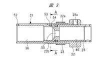
- FIG. 2is an exploded plan view of an inner tube and an end tube shown in FIG. 1. It is a longitudinal cross-sectional view which shows the state which assembled the inner tube and end tube which were shown by FIG. (A) is a cross-sectional view taken along line AA in FIG. 3, (B) is a cross-sectional view showing a state in which the inner tube is rotated 90 degrees from the state shown in (A), and (C) is a modified example. It is sectional drawing which shows the same part. It is a longitudinal cross-sectional view of the spring-type timer in the state which retracted the piston rod. It is a longitudinal cross-sectional view of the spring type timer in the state where the piston rod protrudes.
- the spring type timer 10has a stepped outer tube 11.
- the outer tube 11has a distal end portion 13 provided with a rod cover portion 12, a central portion 15 provided with a male screw 14 and having a larger diameter than the distal end portion, and a proximal end portion 16.
- the piston rod 18is supported in a reciprocating manner in the axial direction by a bearing member 17 mounted in the distal end portion 13, and the projecting end portion of the piston rod 18 projects from a through hole 19 provided in the rod cover portion 12. Yes.
- the piston rod 18moves between the forward limit position shown in FIG. 1 and the reverse limit position shown in FIG.
- the end in the direction in which the piston rod 18 projectsis the tip of each member, and the opposite side is the base.
- the direction in which the piston rod 18 protrudesis defined as forward, and the opposite direction is defined as backward.
- the base end portion 16 of the outer tube 11has an opening, and the inner tube 21 and the end tube 22 are inserted into the outer tube 11 from the opening.
- the male screw 23 provided on the outer peripheral surface of the central portion 22 a of the end tube 22is screwed to the female screw 24 provided on the inner peripheral surface of the base end portion 16 of the outer tube 11, and the end tube 22 is fastened to the outer tube 11. Is done.
- the inner tube 21is rotatably mounted inside the end tube 22, and the outer peripheral surface of the inner tube 21 is in contact with the inner peripheral surface of the end tube 22.
- a base end portion 25 of the inner tube 21protrudes from the end tube 22, and an operation knob 26 is attached to the base end portion 25 by a pin 27.
- the operation knob 26is provided at the proximal end portion of the spring type timer 10.
- a fitting hole 27a into which the pin 27 is fittedis formed in the proximal end portion 25 of the inner tube 21, as shown in FIG.
- the operation knob 26By operating the operation knob 26, the inner tube 21 is rotated and set to a predetermined rotation angle.
- a set screw 28is attached to the end tube 22 in order to prevent the inner tube 21 from rotating.
- the set screw 28is screwed into a screw hole 28 a formed in the end tube 22.
- the piston rod 18is provided with a protrusion 29 that abuts against the rear end surface 17a of the bearing member 17. When the protrusion 29 is abutted against the rear end surface 17a, the piston rod 18 is in the forward limit position.
- a spring receiving cap 31is attached to the tip of the piston rod 18 by a stopper 32. That is, the spring receiving cap 31 is provided at the tip of the spring timer 10.
- a coil spring 33is mounted between the distal end portion of the piston rod 18 and the outer tube 11 in order to urge the piston rod 18 with an elastic force in the forward direction. One end of the coil spring 33 is in contact with the spring receiving cap 31, and the other end is in contact with the stepped portion 34 of the outer tube 11.
- a piston assembly 35is provided at the proximal end of the piston rod 18.
- the piston assembly 35is mounted in a liquid circulation chamber 36 provided in the distal end portion of the inner tube 21 and is movable in the axial direction.
- the liquid circulation chamber 36is filled with oil as an incompressible working medium liquid.
- the liquid circulation chamber 36is partitioned by a piston assembly 35 into a front liquid chamber 36 a on the front side of the piston assembly 35 and a rear liquid chamber 36 b on the rear side.
- the piston assembly 35has an annular piston 37 attached to the proximal end portion of the piston rod 18.
- the inner diameter of the annular piston 37is larger than the outer diameter of the piston rod 18, and an opening / closing passage 38 is formed between the annular piston 37 and the piston rod 18.
- a stopper 41 made of a nutis screwed to a male screw 42 formed on the piston rod 18, and the annular piston 37 is movable between the projection 29 and the stopper 41 in the axial direction.
- the outer diameter of the stopper 41is larger than the inner diameter of the annular piston 37.
- a flat notch 29 a having a smaller radial dimension than the inner diameter of the annular piston 37is formed in the protrusion 29. Therefore, when the piston rod 18 is moved backward so as to be retracted into the outer tube 11, the front end surface of the annular piston 37 comes into contact with the protrusion 29 as shown in FIG. 5, and the rear end surface of the annular piston 37 and the stopper 41. The gap 43 between the two is widened. Thereby, the open / close passage 38 is opened. On the other hand, when the front end of the piston rod 18 is moved forward in the direction of projecting from the outer tube 11, as shown in FIG. 6, the annular piston 37 contacts the stopper 41, and the gap 43 and the open / close passage 38 are closed. Thus, the check valve mechanism 44 is formed by the annular piston 37 and the stopper 41.
- An annular protrusion 45is provided inside the inner tube 21.
- a seal piston 47is incorporated in the cylinder hole 46 on the base end side of the annular protrusion 45 so as to be slidable in the axial direction.
- a seal member 48is attached to the seal piston 47.
- a liquid storage chamber 49is formed by the front surface side of the seal piston 47 and the cylinder hole 46, and the liquid storage chamber 49 communicates with the rear liquid chamber 36 b of the liquid circulation chamber 36 through a communication hole 50 provided in the annular protrusion 45. Yes. Therefore, when the piston rod 18 moves to the forward limit position as shown in FIG. 1 and moves to the backward limit position as shown in FIG. 5, the piston rod 18 enters the liquid circulation chamber 36. A volume of liquid corresponding to the volume that has entered enters the liquid storage chamber 49.
- the inner diameter of the central portion 15 of the outer tube 11is larger than the outer diameter of the distal end portion of the inner tube 21, and a bypass passage 51 is formed between the outer tube 11 and the inner tube 21.
- a semicircular cutout portion 52is provided at the distal end surface of the inner tube 21, and the bypass passage 51 passes through the cutout portion 52 and the front side liquid as shown in FIG. 1. It communicates with the chamber 36a.
- An orifice hole 53is provided in the distal end portion 22 b of the end tube 22, and the orifice hole 53 opens into a gap 51 a formed between the outer peripheral surface of the distal end portion of the end tube 22 and the inner peripheral surface of the outer tube 11. Yes.
- a communication hole 54 having substantially the same inner diameter as the orifice hole 53is formed in the inner tube 21, and the axial position of the communication hole 54 and the axial position of the orifice hole 53 are substantially the same.
- an eccentric groove 55is formed on the outer peripheral surface of the inner tube 21 so as to cross the communication hole 54 in the circumferential direction. As shown in FIGS.
- the eccentric groove 55has the deepest portion of the communication hole 54, and the depth gradually decreases toward the left and right sides in the circumferential direction around the communication hole 54. Has changed. As shown in FIGS. 1 and 4A and 4B, the gap 51a, the orifice hole 53, and the eccentric groove 55 form a part of the bypass passage 51, and the bypass passage 51 includes the communication hole 54. And communicates with the rear liquid chamber 36b.
- FIG. 4Awhen the communication hole 54 faces the orifice hole 53, the opening degree of the bypass passage 51 communicating with the communication hole 54 is maximized. If the inner tube 21 is rotated to the left or right by the operation knob 26 from this state, the opening degree of the bypass passage 51, that is, the communication opening degree between the communication hole 54 and the orifice hole 53 decreases steplessly.
- FIG. 4Bshows a state in which the inner tube 21 is rotated by 90 degrees as the rotation angle ⁇ . In this case, the inner opening surface of the orifice hole 53 is larger than the case shown in FIG. And the bottom surface of the eccentric groove 55 are small.
- the piston rod 18is moved from the backward limit position to the forward limit by the elastic force stored in the coil spring 33.
- the forward speedcan be changed. That is, when the communication opening is set to a predetermined opening, the time for the piston rod 18 to move from the backward limit position to the forward limit position can be set.
- FIG. 4Cis a cross-sectional view showing the same part as FIG. 4A and FIG. 4B, and the communication hole 54 communicates with the deepest part at one end of the eccentric groove 55.
- the groove of the eccentric groove 55becomes shallow.
- the opening degreecan be set more finely than in the case shown in FIG. 4C.
- the liquid injection hole 65is provided in the seal piston 47, and the liquid injection hole 65 is closed by a plug 66 after the inner tube 21 is filled with a predetermined amount of liquid.
- the seal member 61is mounted between the rod cover portion 12 of the outer tube 11 and the bearing member 17.
- a seal member 62is mounted between the outer tube 11 and the end tube 22, and a seal member 63 is mounted between the end tube 22 and the inner tube 21.
- This spring type timer 10can be used for closing an operated member such as a mechanical switch that opens and closes a stopper plug that discharges liquid stored in a tank to the outside.
- the spring timer 10can also be used to automatically close tap water taps, and can also be used to apply a closing force to an open building door. can do.
- the spring timer 10when the spring timer 10 is incorporated in a device including a mechanical switch for opening and closing a stopper, for example, to close the mechanical switch, the spring timer 10 is Attached to the device. Further, the tip end of the piston rod 18 or the tip end surface of the spring receiving cap 31 is in contact with an operated member that is a mechanical switch. As shown in FIG. 1, when the liquid in the tank is discharged to the outside with the piston rod 18 in the forward limit position, the stopper plug is manually opened by a mechanical switch that is an operation member. Operated. By operating the mechanical switch, the piston rod 18 is pushed back.
- FIG. 5shows a state where the piston rod 18 has been pushed to the retract limit position.
- This timeis adjusted by rotating the inner tube 21 with the operation knob 26 and adjusting the opening of the bypass passage 51. After the opening degree of the bypass passage 51 is adjusted, the inner tube 21 can be prevented from rotating by tightening the set screw 28. Since the operation knob 26 is provided at the base end portion of the spring type timer 10, the operation knob 26 can be rotated even if the spring type timer 10 is mounted in the apparatus and the outer tube 11 cannot be rotated by the male screw 14. Can be operated.
- the operation of moving the piston rod 18 forwardmay be performed after the piston rod 18 is operated to the retreat limit position, or may be moved forward at a position before the retreat limit position. Also, the forward movement time to the forward limit position of the piston rod 18 is set by the opening of the communication hole 54.
- the spring timer 10no spring is provided in the inner tube 21, and a piston assembly 35 that partitions the liquid circulation chamber 36 forward and backward and a seal piston that communicates with the liquid circulation chamber 36 are provided.
- the coil spring 33is provided on the protruding end side of the piston rod, and the outer diameter can be reduced. Thereby, the spring-type timer 10 can be reduced in size.
- a flexible filmis not used inside, but it can be set as the spring type timer 10 excellent in durability, and frequent maintenance is also unnecessary.
- This spring type timercan be applied not only for returning the faucet but also as a timer for stopping the discharge of hot water from the shower head in the shower facility, and also for setting the operation time of the mechanical operation member. it can.
- the spring type timercan be used, for example, to automatically close a faucet opened by manual operation over a certain period of time.
Landscapes
- Engineering & Computer Science (AREA)
- General Engineering & Computer Science (AREA)
- Mechanical Engineering (AREA)
- Fluid-Damping Devices (AREA)
Abstract
Description
Translated fromJapanese本発明は、ピストンロッドの後退移動によりスプリングに蓄えられた弾性力により、ロッドを前進移動させる際の前進速度を調整するようにしたスプリング式タイマーに関する。The present invention relates to a spring timer that adjusts the forward speed when the rod is moved forward by the elastic force stored in the spring by the backward movement of the piston rod.
タイマーとして使用される弁機構としては、特許文献1に記載されるように、液体が封入されたシリンダと、貫通孔が設けられたピストンとを備えたものがある。ピストンには貫通孔を開閉する弁部材が設けられ、ピストンロッドを下死点に向けて押し込み移動させるときには、下側の液体は貫通孔等を通ってピストンの上側に流れる。これに対し、ピストンロッドに対する押圧力を解除すると、ピストンにはスプリングにより上方向の弾性力が加わるが、弁部材により貫通孔が閉じられてピストンロッドの上昇速度は低速となる。As a valve mechanism used as a timer, there is a valve mechanism including a cylinder filled with liquid and a piston provided with a through hole, as described in Patent Document 1. The piston is provided with a valve member for opening and closing the through hole. When the piston rod is pushed and moved toward the bottom dead center, the lower liquid flows through the through hole and the like to the upper side of the piston. On the other hand, when the pressing force against the piston rod is released, an upward elastic force is applied to the piston by the spring, but the through hole is closed by the valve member, and the piston rod is raised at a low speed.
この弁機構においては、ピストンロッドが上死点に近づくと、高速復帰溝にも液体を流すことにより、上死点附近のスイッチを作動させるようにしているが、ピストンロッドを下死点位置から上死点位置に復帰させる時間を変化させることはできない。In this valve mechanism, when the piston rod approaches the top dead center, the switch is operated near the top dead center by flowing the liquid also into the high speed return groove, but the piston rod is moved from the bottom dead center position. The time for returning to the top dead center position cannot be changed.
一方、開放された建造物のドアに閉じる方向の操作力を加えるために、特許文献2に記載されるガスばねが開発されている。このガスばねは、管状本体と、この管状本体の先端部から突出するシャフトとを有している。管状本体の内部の流体室に組み込まれた第1のピストン組立体がシャフトの内方端に取り付けられ、第1のピストン組立体と管状本体の基端部との間には、第2のピストン組立体が移動自在に配置されている。流体室には液体が充填され、第2のピストン組立体と管状本体との間の小室にはガスが充填されている。On the other hand, in order to apply an operating force in the closing direction to the door of an open building, a gas spring described in Patent Document 2 has been developed. This gas spring has a tubular main body and a shaft protruding from the tip of the tubular main body. A first piston assembly incorporated in a fluid chamber inside the tubular body is attached to the inner end of the shaft, and a second piston is interposed between the first piston assembly and the proximal end of the tubular body. The assembly is movably arranged. The fluid chamber is filled with liquid, and the small chamber between the second piston assembly and the tubular body is filled with gas.
ガスばねの管状本体の基端部は建造物とドアの一方に取り付けられ、シャフトの先端部は建造物とドアの他方に取り付けられる。ドアを開けるときには、内部のガス圧に抗してシャフトが管状本体の内部に押し込まれる。ガスの圧力によりシャフトが前進駆動されることにより、ドアの閉鎖動作が行われる。シャフトが前進駆動されるときの第1のピストン組立体を通過する液体の流量により、ドアの閉塞速度は設定される。このガスばねを使用すると、ドアが開放された後に一定の時間をかけて、ドアを閉じるというタイマーとして利用することができる。The base end of the tubular body of the gas spring is attached to one of the building and the door, and the tip of the shaft is attached to the other of the building and the door. When the door is opened, the shaft is pushed into the tubular body against the gas pressure inside. As the shaft is driven forward by the pressure of the gas, the door is closed. The closing speed of the door is set by the flow rate of the liquid passing through the first piston assembly when the shaft is driven forward. When this gas spring is used, it can be used as a timer for closing a door after a certain period of time after the door is opened.
特許文献2に記載のように、シャフトの押し込み動作が行われた後に、シャフトをゆっくりと前進動作させると、ドアを一定時間かけて、ゆっくりと自動的に閉鎖することができる。したがって、このようなタイマーを使用すると、第1の位置から第2の位置に人為的に操作される操作部材を、操作部材に対する操作が完了した後に、一定時間をかけて、その操作部材を第2の位置から第1の位置に戻すことができる。例えば、水道水等の液体の出口部分つまり蛇口には、液体の流れの開閉や流量を調整するために操作部材としての水栓が設けられている。公共施設のように、不特定人に使用される水栓には、手動操作で水栓が開かれた後に、一定時間をかけて水栓を自動的に閉じるタイマーの開発が望まれている。さらに、不特定人に使用されるシャワー設備においては、使用者がシャワーヘッドから温水を吐出させてから、一定時間が経過すると、温水の吐出停止を自動的に行うためのタイマーの開発が望まれている。As described in Patent Document 2, when the shaft is slowly moved forward after the shaft is pushed in, the door can be slowly and automatically closed over a certain period of time. Therefore, when such a timer is used, an operation member that is artificially operated from the first position to the second position is moved over a certain period of time after the operation on the operation member is completed. The position can be returned from the position 2 to the first position. For example, a faucet as an operation member is provided at an outlet portion of a liquid such as tap water, that is, a faucet, in order to open / close the liquid flow or adjust the flow rate. For a faucet used by an unspecified person like a public facility, it is desired to develop a timer that automatically closes the faucet over a certain period of time after the faucet is opened manually. Furthermore, in shower facilities used by unspecified persons, it is desirable to develop a timer for automatically stopping hot water discharge after a certain period of time has elapsed since the user discharged hot water from the shower head. ing.
このように、部材を戻す動作をするための機械的なタイマーとしては、その用途に応じて戻し動作が完了するまでの時間が広い範囲にまで及んでおり、同種のタイマーを複数の用途に使用するには、戻し動作時間を広い範囲で調整できるようにする必要がある。しかも、上述したように、水栓やシャワー設備に使用されるタイマーとしては、ドアの閉鎖用のタイマーよりも小型化しなければ、使用することができず、さらに、耐久性に優れ、頻繁なメンテナンス作業を不要とする必要がある。In this way, as a mechanical timer for returning the member, the time until the return operation is completed depends on the application, and the same type of timer is used for multiple applications. Therefore, it is necessary to be able to adjust the return operation time in a wide range. Moreover, as described above, the timer used for faucets and shower facilities cannot be used unless it is made smaller than the timer for closing the door, and is excellent in durability and frequent maintenance. It is necessary to make the work unnecessary.
本発明の目的は、操作部材を戻し動作するための小型のスプリング式タイマーを提供することにある。An object of the present invention is to provide a small spring timer for returning the operation member.
本発明のスプリング式タイマーは、ピストンロッドが後退限位置と前進限位置との間を軸方向に往復動自在に装着され、前記ピストンロッドが先端部から突出するアウターチューブと、液体循環室が形成され、前記アウターチューブ内に回転自在に装着されるインナーチューブと、前記ピストンロッドの基端部に設けられ、前記液体循環室を前側液体室と後側液体室とに仕切るピストン組立体と、前記ピストンロッドの先端部と前記アウターチューブとの間に装着され、前記ピストンロッドに前進方向の弾性力を付勢するスプリングと、前記アウターチューブと前記インナーチューブとの間に設けられ、前記前側液体室と前記後側液体室とを連通させるバイパス通路と、前記インナーチューブに径方向に貫通して形成され、前記インナーチューブの回転に伴って前記バイパス通路の開度を変化させる連通孔と、を有し、前記ピストンロッドが後退限位置から前進限位置に向けて前記スプリングの弾性力による前進速度を前記バイパス通路の開度により設定する。In the spring timer of the present invention, the piston rod is mounted so as to be capable of reciprocating between the backward limit position and the forward limit position in the axial direction, and an outer tube in which the piston rod projects from the tip portion and a liquid circulation chamber are formed. An inner tube rotatably mounted in the outer tube, a piston assembly provided at a base end portion of the piston rod, and partitioning the liquid circulation chamber into a front liquid chamber and a rear liquid chamber, A spring mounted between a distal end portion of a piston rod and the outer tube and energizing the piston rod with an elastic force in a forward direction; and provided between the outer tube and the inner tube; And a bypass passage that communicates with the rear liquid chamber, and is formed through the inner tube in a radial direction, A communication hole that changes the opening degree of the bypass passage as the probe rotates, and the piston rod controls the forward speed by the elastic force of the spring from the backward limit position to the forward limit position. Set according to the degree of opening.
ピストンロッドを往復動自在に収容するアウターチューブの内部には、インナーチューブが組み込まれ、インナーチューブ内に形成された液体循環室の内部には、ピストンロッドに設けられたピストン組立体が装着されており、インナーチューブの内部にはスプリングが設けられていないので、アウターチューブを小径とすることができ、スプリング式タイマーを小型化することができる。An inner tube is built into the outer tube that reciprocally accommodates the piston rod, and a piston assembly provided in the piston rod is mounted inside the liquid circulation chamber formed in the inner tube. In addition, since no spring is provided inside the inner tube, the outer tube can have a small diameter, and the spring timer can be downsized.
以下、本発明の実施の形態を図面に基づいて詳細に説明する。図1に示されるように、スプリング式タイマー10は段付きのアウターチューブ11を有している。アウターチューブ11は、ロッドカバー部12が設けられた先端部13と、雄ねじ14が設けられ先端部よりも大径の中央部15と、基端部16とを有している。先端部13内に装着された軸受部材17によりピストンロッド18が軸方向に往復動自在に支持され、ピストンロッド18の先端の突出端部がロッドカバー部12に設けられた貫通孔19から突出している。ピストンロッド18は、図1に示される前進限位置から図5に示される後退限位置の間を移動する。この明細書においては、ピストンロッド18が突出する方向の端部を各部材の先端部とし、反対側を基端部とする。また、ピストンロッド18が突出する方向を前進とし、反対方向を後退とする。Hereinafter, embodiments of the present invention will be described in detail with reference to the drawings. As shown in FIG. 1, the
アウターチューブ11の基端部16は開口部を有し、開口部からインナーチューブ21とエンドチューブ22がアウターチューブ11の内部に挿入される。エンドチューブ22の中央部22aの外周面に設けられた雄ねじ23は、アウターチューブ11の基端部16の内周面に設けられた雌ねじ24にねじ結合され、エンドチューブ22はアウターチューブ11に締結される。インナーチューブ21はエンドチューブ22の内側に回転自在に装着されるとともに、インナーチューブ21の外周面は、エンドチューブ22の内周面に接触する。インナーチューブ21の基端部25はエンドチューブ22よりも突出しており、操作ノブ26が基端部25にピン27により取り付けられている。すなわち、操作ノブ26は、スプリング式タイマー10の基端部に設けられている。ピン27が嵌合される嵌合孔27aが、図2に示されように、インナーチューブ21の基端部25に形成されている。操作ノブ26を操作することによりインナーチューブ21が回転され、所定の回転角度に設定される。インナーチューブ21の回転角度を設定した後、インナーチューブ21が回転しないようにするために、止めねじ28がエンドチューブ22に取り付けられている。止めねじ28は、エンドチューブ22に形成されたねじ孔28aにねじ結合される。The
ピストンロッド18には、軸受部材17の後端面17aに突き当てられる突起部29が設けられている。突起部29が後端面17aに突き当てられると、ピストンロッド18は前進限位置となる。ばね受けキャップ31がピストンロッド18の先端部に止具32により取り付けられている。すなわち、ばね受けキャップ31は、スプリング式タイマー10の先端部に設けられている。ピストンロッド18に前進方向の弾性力を付勢するために、コイルスプリング33がピストンロッド18の先端部とアウターチューブ11との間に装着されている。コイルスプリング33の一端は、ばね受けキャップ31に接触し、他端はアウターチューブ11の段差部34に接触している。The
ピストン組立体35がピストンロッド18の基端部に設けられている。ピストン組立体35は、インナーチューブ21の先端部内に設けられた液体循環室36内に装着され、軸方向に移動自在である。液体循環室36内には、非圧縮性の作動媒体液として油が充填される。液体循環室36はピストン組立体35の前面側の前側液体室36aと、後面側の後側液体室36bとにピストン組立体35により仕切られている。ピストン組立体35は、ピストンロッド18の基端部に装着される環状ピストン37を有している。環状ピストン37の内径はピストンロッド18の外径よりも大きく、開閉通路38が、環状ピストン37とピストンロッド18との間に形成されている。ナットからなるストッパ41がピストンロッド18に形成された雄ねじ42にねじ結合され、環状ピストン37は突起部29とストッパ41との間を軸方向に移動自在である。A
ストッパ41の外径は環状ピストン37の内径よりも大径である。環状ピストン37の内径よりも径方向寸法が小さい平坦な切欠き部29aが突起部29に形成されている。したがって、ピストンロッド18をアウターチューブ11内に引っ込めるように後退移動させるときには、図5に示されるように、環状ピストン37の前端面は突起部29に接触し、環状ピストン37の後端面とストッパ41との間の隙間43は広がる。これにより、開閉通路38は開放される。一方、ピストンロッド18の先端部をアウターチューブ11から突出させる方向に前進移動させると、図6に示されるように、環状ピストン37はストッパ41に接触し、隙間43と開閉通路38は閉じられる。このように、環状ピストン37とストッパ41とにより逆止弁機構44が形成されている。The outer diameter of the
環状突起45がインナーチューブ21の内部に設けられている。この環状突起45の基端部側のシリンダ孔46にはシールピストン47が軸方向に摺動自在に組み込まれている。シール部材48がシールピストン47に装着されている。シールピストン47の前面側とシリンダ孔46とにより液体貯留室49が形成され、液体貯留室49は環状突起45に設けられた連通孔50により液体循環室36の後側液体室36bに連通している。したがって、図1に示されるように、ピストンロッド18が前進限位置まで突出していた状態から、図5に示されるように、後退限位置まで移動すると、ピストンロッド18のうち液体循環室36内に入り込んだ容積に相当する容積の液体が液体貯留室49に入り込む。An
アウターチューブ11の中央部15の内径は、インナーチューブ21の先端部の外径よりも大きく、バイパス通路51がアウターチューブ11とインナーチューブ21の間に形成されている。図2に示されるように、半円形状の切欠き部52がインナーチューブ21の先端面に設けられており、図1に示されるように、バイパス通路51は切欠き部52を介して前側液体室36aに連通している。The inner diameter of the
オリフィス孔53がエンドチューブ22の先端部22bに設けられ、オリフィス孔53はエンドチューブ22の先端部の外周面と、アウターチューブ11の内周面との間に形成される隙間51aに開口している。オリフィス孔53とほぼ同一内径の連通孔54がインナーチューブ21に形成され、連通孔54の軸方向位置と、オリフィス孔53の軸方向位置は、ほぼ同じである。図2に示されるように、連通孔54を円周方向に横切るように、偏心溝55がインナーチューブ21の外周面に形成されている。偏心溝55は、図4(A)、(B)に示されるように、連通孔54の部分が最も深く、連通孔54を中心に円周方向左右両側に向けて漸次深さが浅くなるように変化している。図1および図4(A)、(B)に示されるように、隙間51a、オリフィス孔53および偏心溝55がバイパス通路51の一部を形成しており、バイパス通路51は、連通孔54を介して後側液体室36bに連通している。An
したがって、図4(A)に示されるように、連通孔54がオリフィス孔53に向き合っているときには、連通孔54に連通するバイパス通路51の開度は最大となる。この状態から、操作ノブ26によりインナーチューブ21を左右いずれか一方に回転させると、バイパス通路51の開度、つまり連通孔54とオリフィス孔53との連通開度が無段階に小さくなる。図4(B)は、インナーチューブ21を回転角度θとして90度回転させた状態を示しており、この場合には、図4(A)に示される場合よりも、オリフィス孔53の内側開口面と偏心溝55の底面との間の間隔が小さくなっている。Therefore, as shown in FIG. 4A, when the
このように、インナーチューブ21の回転に伴って連通孔54とオリフィス孔53との連通開度を変化させると、コイルスプリング33に蓄えられた弾性力によって、ピストンロッド18が後退限位置から前進限位置に前進移動させるときの、前進速度を変化させることができる。つまり、連通開度を所定の開度に設定すると、ピストンロッド18が後退限位置から前進限位置まで移動する時間を設定することができる。As described above, when the communication opening degree between the
図4(C)は図4(A)、(B)と同様の部分を示す断面図であり、連通孔54は偏心溝55の一端部における最も深い部分に連通されており、インナーチューブ21を図4(C)において、左方向に回転させると、偏心溝55の溝が浅くなる。約330度程度回転させると、バイパス通路51と連通孔54との連通は遮断される。このように、図4(C)に示された形態においては、図4(A)に示した場合よりも、細かく開度設定を行うことができる。FIG. 4C is a cross-sectional view showing the same part as FIG. 4A and FIG. 4B, and the
シールピストン47には液体注入孔65が設けられており、インナーチューブ21内に所定量の液体が充填された後に、液体注入孔65はプラグ66により閉じられる。スプリング式タイマー10の内部に充填された液体が外部に漏出するのを防止するために、シール部材61がアウターチューブ11のロッドカバー部12と軸受部材17との間に装着される。シール部材62がアウターチューブ11とエンドチューブ22との間に装着され、シール部材63がエンドチューブ22とインナーチューブ21との間に装着される。The
このスプリング式タイマー10は、例えば、タンク内に収容された液体を外部に吐出する止め栓を開閉する機械式スイッチのような被操作部材を閉鎖操作するために使用することができる。また、このスプリング式タイマー10は、水道水の水栓を自動的に閉鎖するために使用することができ、さらには、開放された建造物のドアに閉じる方向の操作力を加えるためにも使用することができる。This
このスプリング式タイマー10が、上述のように、例えば、止め栓を開閉する機械式スイッチを備える装置に、機械式スイッチを閉塞操作するために組み込まれるときには、スプリング式タイマー10は、雄ねじ14によって、その装置に取り付けられる。さらにピストンロッド18の先端もしくはばね受けキャップ31の先端面は、機械式スイッチである被操作部材に接触する。図1に示されるように、ピストンロッド18が前進限位置となっている状態のもとで、タンク内の液体を外部に排出するときには、人手により操作部材である機械式スイッチにより止め栓が開放操作される。機械式スイッチの操作によってピストンロッド18が後退する方向に押し込まれる。ピストンロッド18が押し込まれると、後側液体室36b内の液体は、隙間43、開閉通路38を通って前側液体室36aに流れ、さらに、バイパス通路51を通って前側液体室36aに流れる。このときには、液体循環室36内の液体の流れには大きな流通抵抗が加わらないので、容易にピストンロッド18をコイルスプリング33の弾性力に抗して後退移動させることができる。これにより、止め栓は全開状態に操作される。図5は、ピストンロッド18が後退限位置まで押し込み操作された状態を示す。As described above, when the
機械式スイッチから手が離れると、ピストンロッド18はコイルスプリング33による前進方向の弾性力により突出する方向に駆動され、操作部材である機械式スイッチは閉じる方向に駆動される。このときには、図6に示されるように、環状ピストン37はストッパ41に当接して、隙間43が閉じられる。このため、前側液体室36a内の液体は、バイパス通路51のみを通って後側液体室36bに向けて流れるので、ピストンロッド18の前進速度は、ピストンロッド18を後退させるときよりも、低下する。したがって、止め栓が開かれてから閉じられまでの戻し動作時間は、バイパス通路51を通って前側液体室36aから後側液体室36bに流入する液体の流速により設定される。この時間は、操作ノブ26によりインナーチューブ21を回転させて、バイパス通路51の開度を調整することにより、調整される。バイパス通路51の開度を調整した後、止めねじ28を締めることで、インナーチューブ21の回転を防ぐことができる。操作ノブ26が、スプリング式タイマー10の基端部に設けられているので、雄ねじ14によって、スプリング式タイマー10が、装置内に取り付けられてアウターチューブ11が回転できない状態でも、操作ノブ26を回転操作することができる。When the hand is released from the mechanical switch, the
ピストンロッド18を前進移動させる操作は、ピストンロッド18が後退限位置まで操作されてから行うようにしても良く、後退限位置の手前の位置で前進移動させるようにしても良く、いずれの場合にもピストンロッド18の前進限位置までの前進移動時間が連通孔54の開度により設定される。The operation of moving the
このスプリング式タイマー10においては、インナーチューブ21の内部にはスプリングが設けられておらず、液体循環室36を前後に仕切るピストン組立体35と、液体循環室36に連通するシールピストンとが設けられているのみであり、コイルスプリング33はピストンロッドの突出端側に設けられており、外径を小さくすることができる。これにより、スプリング式タイマー10を小型化することが可能となる。特許文献1のように、内部に可撓性被膜を用いることがなく、耐久性に優れたスプリング式タイマー10とすることができ、頻繁のメンテナンスも不要となる。In the
本発明は前記実施の形態に限定されるものではなく、その要旨を逸脱しない範囲で種々変更可能である。このスプリング式タイマーは、水栓の戻し用のみならず、シャワー設備においてシャワーヘッドからの温水の吐出停止のタイマーとして、さらには機械的な操作部材の操作時間の設定のためにも適用することができる。The present invention is not limited to the embodiment described above, and various modifications can be made without departing from the scope of the invention. This spring type timer can be applied not only for returning the faucet but also as a timer for stopping the discharge of hot water from the shower head in the shower facility, and also for setting the operation time of the mechanical operation member. it can.
スプリング式タイマーは、例えば、手動操作により開かれた水栓を、一定時間をかけて自動的に閉じるために使用することができる。The spring type timer can be used, for example, to automatically close a faucet opened by manual operation over a certain period of time.
Claims (4)
Translated fromJapanese液体循環室が形成され、前記アウターチューブ内に回転自在に装着されるインナーチューブと、
前記ピストンロッドの基端部に設けられ、前記液体循環室を前側液体室と後側液体室とに仕切るピストン組立体と、
前記ピストンロッドの先端部と前記アウターチューブとの間に装着され、前記ピストンロッドに前進方向の弾性力を付勢するスプリングと、
前記アウターチューブと前記インナーチューブとの間に設けられ、前記前側液体室と前記後側液体室とを連通させるバイパス通路と、
前記インナーチューブに径方向に貫通して形成され、前記インナーチューブの回転に伴って前記バイパス通路の開度を変化させる連通孔と、を有し、
前記ピストンロッドが後退限位置から前進限位置に向けて前記スプリングの弾性力による前進速度を前記バイパス通路の開度により設定する、スプリング式タイマー。An outer tube in which a piston rod is reciprocally mounted in an axial direction between a backward limit position and a forward limit position, and the piston rod protrudes from a tip portion;
An inner tube in which a liquid circulation chamber is formed and rotatably mounted in the outer tube;
A piston assembly provided at a base end portion of the piston rod and partitioning the liquid circulation chamber into a front liquid chamber and a rear liquid chamber;
A spring that is mounted between the tip of the piston rod and the outer tube and biases the piston rod with an elastic force in a forward direction;
A bypass passage that is provided between the outer tube and the inner tube, and communicates the front liquid chamber and the rear liquid chamber;
A through hole that is formed through the inner tube in the radial direction and changes the opening of the bypass passage as the inner tube rotates.
A spring-type timer in which the piston rod sets a forward speed due to the elastic force of the spring from the backward limit position to the forward limit position by the opening of the bypass passage.
Applications Claiming Priority (2)
| Application Number | Priority Date | Filing Date | Title |
|---|---|---|---|
| JP2018098025AJP6998830B2 (en) | 2018-05-22 | 2018-05-22 | Spring timer |
| JP2018-098025 | 2018-05-22 |
Publications (1)
| Publication Number | Publication Date |
|---|---|
| WO2019225132A1true WO2019225132A1 (en) | 2019-11-28 |
Family
ID=68617072
Family Applications (1)
| Application Number | Title | Priority Date | Filing Date |
|---|---|---|---|
| PCT/JP2019/011282CeasedWO2019225132A1 (en) | 2018-05-22 | 2019-03-18 | Spring-type timer |
Country Status (2)
| Country | Link |
|---|---|
| JP (1) | JP6998830B2 (en) |
| WO (1) | WO2019225132A1 (en) |
Cited By (1)
| Publication number | Priority date | Publication date | Assignee | Title |
|---|---|---|---|---|
| JP2021013412A (en)* | 2019-07-10 | 2021-02-12 | ソニー株式会社 | Medical observation system, control device and control method |
Citations (4)
| Publication number | Priority date | Publication date | Assignee | Title |
|---|---|---|---|---|
| JPS51110835A (en)* | 1975-03-24 | 1976-09-30 | Tokico Ltd | DOAKUROOZA |
| JPS5742235U (en)* | 1980-08-21 | 1982-03-08 | ||
| JPS5841881U (en)* | 1981-09-17 | 1983-03-19 | 株式会社セコ−技研 | valve mechanism |
| JPH08177924A (en)* | 1994-09-13 | 1996-07-12 | Avm Inc | Adjusted-speed gas spring |
- 2018
- 2018-05-22JPJP2018098025Apatent/JP6998830B2/enactiveActive
- 2019
- 2019-03-18WOPCT/JP2019/011282patent/WO2019225132A1/ennot_activeCeased
Patent Citations (4)
| Publication number | Priority date | Publication date | Assignee | Title |
|---|---|---|---|---|
| JPS51110835A (en)* | 1975-03-24 | 1976-09-30 | Tokico Ltd | DOAKUROOZA |
| JPS5742235U (en)* | 1980-08-21 | 1982-03-08 | ||
| JPS5841881U (en)* | 1981-09-17 | 1983-03-19 | 株式会社セコ−技研 | valve mechanism |
| JPH08177924A (en)* | 1994-09-13 | 1996-07-12 | Avm Inc | Adjusted-speed gas spring |
Cited By (3)
| Publication number | Priority date | Publication date | Assignee | Title |
|---|---|---|---|---|
| JP2021013412A (en)* | 2019-07-10 | 2021-02-12 | ソニー株式会社 | Medical observation system, control device and control method |
| JP7480477B2 (en) | 2019-07-10 | 2024-05-10 | ソニーグループ株式会社 | Medical observation system, control device and control method |
| US12349860B2 (en) | 2019-07-10 | 2025-07-08 | Sony Group Corporation | Medical observation system, control device, and control method |
Also Published As
| Publication number | Publication date |
|---|---|
| JP2019203286A (en) | 2019-11-28 |
| JP6998830B2 (en) | 2022-01-18 |
Similar Documents
| Publication | Publication Date | Title |
|---|---|---|
| US9297475B2 (en) | System for adjusting water in a shower, bathroom, or kitchen sink | |
| US4052035A (en) | Remotely-controlled valve | |
| US2725891A (en) | Hydraulically operated valve | |
| US4051869A (en) | Mixing valve | |
| EP2865928B1 (en) | Valve | |
| CN113245080B (en) | Drain valve and water outlet device | |
| TW201818008A (en) | Valve device capable of fast switching and fine adjustment of flow | |
| US20080053528A1 (en) | Diaphragm pressure balancing valves | |
| JP6998830B2 (en) | Spring timer | |
| US10751746B2 (en) | Swivel shower having a fluid pressure driven swivel body | |
| JP2001095710A (en) | Water discharge equipment | |
| TWI526643B (en) | Low speed elbow valve | |
| CN207961713U (en) | A kind of water channel switching structure easy to use and the shower with the structure and shower system | |
| US7481413B2 (en) | Flush actuator assembly and method therefor | |
| US3342448A (en) | Self-closing faucet | |
| KR20180017878A (en) | Linear Motion Glove Valve | |
| JP2001095709A (en) | Water discharge equipment | |
| CN206656002U (en) | Thrift lock and squirt toy | |
| EP0328543B1 (en) | A mixer valve of the single lever type incorporating means for avoiding pressure surges during the final stage of lever movement in the valve closing direction | |
| RU2658972C2 (en) | Method of controlling flow of water and the device for its implementation | |
| JPS6118294Y2 (en) | ||
| JP4116742B2 (en) | Water discharge device | |
| US4273292A (en) | Self-closing shower head | |
| GB1590757A (en) | Remotely-controlled valve | |
| JPH06174114A (en) | Single lever mixing valve |
Legal Events
| Date | Code | Title | Description |
|---|---|---|---|
| 121 | Ep: the epo has been informed by wipo that ep was designated in this application | Ref document number:19807687 Country of ref document:EP Kind code of ref document:A1 | |
| NENP | Non-entry into the national phase | Ref country code:DE | |
| 122 | Ep: pct application non-entry in european phase | Ref document number:19807687 Country of ref document:EP Kind code of ref document:A1 |