WO2019220738A1 - Optical treatment device and optical treatment method - Google Patents
Optical treatment device and optical treatment methodDownload PDFInfo
- Publication number
- WO2019220738A1 WO2019220738A1PCT/JP2019/007365JP2019007365WWO2019220738A1WO 2019220738 A1WO2019220738 A1WO 2019220738A1JP 2019007365 WJP2019007365 WJP 2019007365WWO 2019220738 A1WO2019220738 A1WO 2019220738A1
- Authority
- WO
- WIPO (PCT)
- Prior art keywords
- balloon
- catheter
- drainage
- bladder
- lumen
- Prior art date
- Legal status (The legal status is an assumption and is not a legal conclusion. Google has not performed a legal analysis and makes no representation as to the accuracy of the status listed.)
- Ceased
Links
Images


Classifications
- A—HUMAN NECESSITIES
- A61—MEDICAL OR VETERINARY SCIENCE; HYGIENE
- A61N—ELECTROTHERAPY; MAGNETOTHERAPY; RADIATION THERAPY; ULTRASOUND THERAPY
- A61N5/00—Radiation therapy
- A61N5/06—Radiation therapy using light
- A61N5/0613—Apparatus adapted for a specific treatment
- A61N5/062—Photodynamic therapy, i.e. excitation of an agent
- A—HUMAN NECESSITIES
- A61—MEDICAL OR VETERINARY SCIENCE; HYGIENE
- A61M—DEVICES FOR INTRODUCING MEDIA INTO, OR ONTO, THE BODY; DEVICES FOR TRANSDUCING BODY MEDIA OR FOR TAKING MEDIA FROM THE BODY; DEVICES FOR PRODUCING OR ENDING SLEEP OR STUPOR
- A61M25/00—Catheters; Hollow probes
- A61M25/10—Balloon catheters
- A—HUMAN NECESSITIES
- A61—MEDICAL OR VETERINARY SCIENCE; HYGIENE
- A61N—ELECTROTHERAPY; MAGNETOTHERAPY; RADIATION THERAPY; ULTRASOUND THERAPY
- A61N5/00—Radiation therapy
- A61N5/06—Radiation therapy using light
- A61N5/0601—Apparatus for use inside the body
- A61N5/0603—Apparatus for use inside the body for treatment of body cavities
- A—HUMAN NECESSITIES
- A61—MEDICAL OR VETERINARY SCIENCE; HYGIENE
- A61M—DEVICES FOR INTRODUCING MEDIA INTO, OR ONTO, THE BODY; DEVICES FOR TRANSDUCING BODY MEDIA OR FOR TAKING MEDIA FROM THE BODY; DEVICES FOR PRODUCING OR ENDING SLEEP OR STUPOR
- A61M25/00—Catheters; Hollow probes
- A61M25/10—Balloon catheters
- A61M2025/1043—Balloon catheters with special features or adapted for special applications
- A61M2025/1047—Balloon catheters with special features or adapted for special applications having centering means, e.g. balloons having an appropriate shape
- A—HUMAN NECESSITIES
- A61—MEDICAL OR VETERINARY SCIENCE; HYGIENE
- A61M—DEVICES FOR INTRODUCING MEDIA INTO, OR ONTO, THE BODY; DEVICES FOR TRANSDUCING BODY MEDIA OR FOR TAKING MEDIA FROM THE BODY; DEVICES FOR PRODUCING OR ENDING SLEEP OR STUPOR
- A61M2210/00—Anatomical parts of the body
- A61M2210/10—Trunk
- A61M2210/1078—Urinary tract
- A61M2210/1085—Bladder
- A—HUMAN NECESSITIES
- A61—MEDICAL OR VETERINARY SCIENCE; HYGIENE
- A61N—ELECTROTHERAPY; MAGNETOTHERAPY; RADIATION THERAPY; ULTRASOUND THERAPY
- A61N5/00—Radiation therapy
- A61N2005/002—Cooling systems
- A61N2005/005—Cooling systems for cooling the radiator
- A—HUMAN NECESSITIES
- A61—MEDICAL OR VETERINARY SCIENCE; HYGIENE
- A61N—ELECTROTHERAPY; MAGNETOTHERAPY; RADIATION THERAPY; ULTRASOUND THERAPY
- A61N5/00—Radiation therapy
- A61N5/06—Radiation therapy using light
- A61N5/0601—Apparatus for use inside the body
- A61N5/0603—Apparatus for use inside the body for treatment of body cavities
- A61N2005/061—Bladder and/or urethra
- A—HUMAN NECESSITIES
- A61—MEDICAL OR VETERINARY SCIENCE; HYGIENE
- A61N—ELECTROTHERAPY; MAGNETOTHERAPY; RADIATION THERAPY; ULTRASOUND THERAPY
- A61N5/00—Radiation therapy
- A61N5/06—Radiation therapy using light
- A61N2005/063—Radiation therapy using light comprising light transmitting means, e.g. optical fibres
- A—HUMAN NECESSITIES
- A61—MEDICAL OR VETERINARY SCIENCE; HYGIENE
- A61N—ELECTROTHERAPY; MAGNETOTHERAPY; RADIATION THERAPY; ULTRASOUND THERAPY
- A61N5/00—Radiation therapy
- A61N5/06—Radiation therapy using light
- A61N2005/0632—Constructional aspects of the apparatus
Definitions
- the present inventionrelates to an optical treatment apparatus for performing treatment by irradiating light to a treatment site, and an optical treatment method using the optical treatment apparatus.
- PITphotoimmunotherapy
- PDTphotodynamic therapy
- Japanese Patent No. 6127045discloses contacting a cell containing a cell surface protein with a therapeutically effective amount of one or more antibody-IR700 molecules, wherein the antibody specifically binds to the cell surface protein. Irradiating the cells at a wavelength of 660-740 nm and at a dose of at least 1 Jcm-2; contacting the cells with one or more therapeutic agents about 0-8 hours after irradiation of the cells; Thus, a method of killing a cell is shown comprising the step of killing the cell.
- Exemplary tumors, such as cancers that can be treated in this way,include bladder cancer.
- the phototherapy probe inserted into the bladderis provided with a functional unit that diffuses light.
- urination with a catheteris assumed to prevent a decrease in light quantity due to urine during light irradiation.
- the catheterneeds two lumens. The outer diameter of a catheter having two lumens is larger than the outer diameter of a single catheter, and the insertion into the bladder is reduced.
- heatis generated when a large amount of light is irradiated on the entire tissue, and the diffusion functional unit may be damaged by the heat.
- the present inventionhas been made in view of the above circumstances, and the durability of the functional unit that diffuses light by reducing the generation of heat when a large amount of light is irradiated without reducing the insertion into the bladder. It is an object of the present invention to provide an improved optical therapeutic apparatus with excellent usability and an optical therapeutic method using the therapeutic apparatus.
- An optical treatment apparatusincludes a drainage catheter having a drainage lumen, a shaft that can be inserted into and removed from the drainage lumen of the drainage catheter, and the shaft.
- a balloonprovided at one end of the shaft and a port provided at the other end of the shaft through which a liquid for inflating the balloon can be injected, and the port and the balloon are in communication with the shaft
- a light irradiatorcapable of irradiating light of a predetermined wavelength from the diffusion function part at the tip.
- An optical treatment methodincludes an arrangement step of disposing a distal end portion of a drainage catheter having a drainage lumen capable of draining urine in a bladder into the bladder, and the drainage catheter by using the drainage catheter.
- the figure explaining an optical treatment apparatusThe figure explaining the step which arrange
- the figure explaining the probe / balloon one-piece combination which united the treatment probe and the balloon catheter integrallyThe figure explaining the step which inserts a probe balloon combination set into the drainage lumen
- the figure explaining the other structural example of a drainage catheterThe figure explaining the probe / balloon / drainage catheter integrated set in which the drainage catheter of another configuration and the probe / balloon integrated set are combined integrally
- FIG. 5Bis a diagram showing an example of the case where the probe / balloon integrated set is reinserted into the drainage lumen of the drainage catheter after the state shown in FIG. 5B and the balloon is placed in the bladder.
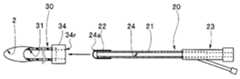
- the optical treatment apparatus 1includes a treatment probe 10, a balloon catheter 20, and a drainage catheter 30.
- the treatment probe 10is a light irradiator including a light irradiator 12 on a long and thin fiber probe 11 having a predetermined outer diameter.
- the light irradiation unit 12is a light diffusion function unit, and is provided on the side surface of the probe tip, which is one end side of the fiber probe 11.
- the probe base end part which is the other end side of the fiber probe 11is a light source connection part 13 connected to a light source device (not shown).
- Illumination light emitted from the light source deviceenters the light source connection unit 13, is transmitted through the fiber probe 11, and is emitted radially (omnidirectional) from the light irradiation unit 12 to the fiber probe central axis a ⁇ b> 11. ing.
- the balloon catheter 20includes a shaft 21, a balloon 22, and a dual-purpose port 23.
- the shaft 21is a thin and translucent tube body, and is made of nylon, silicon, or Teflon (registered trademark).
- the shaft 21includes one lumen 24 along the shaft axis a21.
- the lumen 24 of the shaft 21is an injection lumen.
- the inner diameter of the injection lumen 24is larger than the outer diameter of the fiber probe 11. Therefore, the fiber probe 11 can be inserted into the injection lumen 24 of the shaft 21.
- One opening of the injection lumen 24 provided on one end side of the shaft 21is a balloon opening 24a.
- a balloon 22is provided at one end of the shaft 21 on the balloon opening 24a side.
- the balloon 22is a translucent bag having an opening on one side.
- An O-ring-shaped balloon fixing portion 22 ais provided on the opening side of the balloon 22.
- the balloon fixing portion 22ais fixedly attached to a predetermined position on the outer peripheral surface of the distal end side of the shaft 21 by welding or bonding.
- the balloon 22is supplied into the injection lumen 24 and inflated when liquid is injected into the balloon 22 from the balloon opening 24a.
- the other opening of the injection lumen 24 provided on the other end side of the shaft 21is a port opening 24b.
- a shared port 23is fixed to the other end of the shaft on the side of the port opening 24b.
- the dual-purpose port 23includes a probe port 25 and a liquid port 26.
- the probe port 25extends in the proximal direction from the shaft proximal end along the shaft axis a21 which is the longitudinal axis of the shaft 21.
- the fiber probe 11is inserted into the probe port 25 from an insertion port (not shown) on the base end face side as indicated by an arrow.
- the fiber probe 11passes through the probe port 25 and is inserted into the injection lumen 24 of the shaft 21.
- the liquid port 26intersects the shaft axis a21 at a predetermined angle ⁇ and extends obliquely from the side of the probe port 25 in the proximal direction.
- the liquid port 26is a liquid injection port, and is connected to, for example, a syringe (not shown). As a result, the liquid in the syringe passes through the liquid port 26 and the injection lumen 24 and is injected into the balloon 22 from the balloon opening 24a.
- Numeral 27ais a probe insertion part.
- the probe insertion portion 27ais provided with a holding portion (not shown).
- the holding portionhas a function of a sealing cock that prevents the liquid in the balloon 22 and the injection lumen 24 from leaking to the outside, and a function of holding the arrangement position of the fiber probe 11 in the injection lumen 24. ing.
- Numeral 27bis a syringe mounting part.
- a syringecan be attached to and detached from the syringe mounting portion 27b. The syringe is held in a state of being attached to the syringe attachment portion 27b.
- the liquid in the balloon catheter 20is prevented from leaking to the outside, and the balloon 22 is held in an inflated state. .
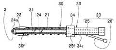
- the drainage catheter 30is an elongated tube body made of nylon, silicon, or Teflon (registered trademark).
- the drainage catheter 30includes one lumen 31 along the catheter axis a30.
- the lumen 31 of the drainage catheter 30is a drainage lumen.
- the inner diameter of the drainage lumen 31is set to be a predetermined dimension larger than the outer diameter of the balloon fixing portion 22a that is the maximum outer diameter within the effective length of the shaft 21 (L21 in the figure). Therefore, the shaft 21 provided with the balloon 22 can pass through the drainage lumen 31 of the drainage catheter 30.
- Balloon insertion portion 34is fixed on the other opening 33 side.
- the shaft 21 provided with the balloon 22 of the balloon catheter 20can be inserted into the balloon insertion portion 34.
- the end of the shaft 21 provided with the balloon 22 on the side of the balloon opening 24 apasses through the balloon insertion portion 34 and the drainage lumen 31 and is led out from one opening 32 to the outside on the distal end side of the drainage catheter 30. It has come to be.
- the balloon catheter effective length L20is set in advance longer than the drainage catheter effective length L30 of the drainage catheter 30.
- L30is the distance from the distal end of the drainage catheter 30 to the distal end surface of the balloon insertion portion 34.
- L21is the effective length of the shaft 21, and is the distance from the tip surface of the shaft 21 to the tip surface of the probe port 25.
- Lis the distance from the shaft tip surface 21f to the balloon attachment portion 21a.
- a urine pack(not shown) can be attached to and detached from the balloon insertion portion 34.
- the balloon insertion portion 34is provided with a holding portion (not shown).
- the holding parthas a function of holding the state where the shaft 21 or the urine pack is disposed in the balloon insertion part 34, and the liquid in the lumen is exposed to the outside in the state where the shaft 21 or the urine pack is disposed in the balloon insertion part 34 And a function of a sealing cock for preventing leakage.
- the drainage catheter 30is provided with one drainage lumen 31 without providing two lumens.
- a shaft 21 provided with a balloon 22 included in the balloon catheter 20 on the side of the balloon opening 24acan be inserted into the drainage lumen 31.
- the fiber scope 11 of the therapeutic probe 10can be inserted into the injection lumen 24 of the shaft 21. Therefore, it is possible to prevent the occurrence of a problem that the outer diameter of the drainage catheter 30 is increased and the insertability into the bladder is lowered.
- the medical stafffirst discharges the urine in the bladder, and therefore the drainage catheter 30 having the drainage lumen 31 as shown in FIG. 2A.
- the tipis placed in the bladder 2. Then, the urine in the bladder is discharged through the drainage lumen 31 of the drainage catheter 30.
- the medical staffinserts the balloon catheter 20 into the drainage catheter 30. That is, as shown in FIG. 2B, the end of the shaft 21 provided with the balloon 22 on the side of the balloon opening 24 a is opposed to the base end surface 34 r of the balloon insertion portion 34. Then, the end portion on the balloon opening 24 a side is inserted into the balloon insertion portion 34 and guided into the drainage lumen 31 of the drainage catheter 30.
- the medical staffbrings the distal end surface 25f of the probe port 25 included in the balloon catheter 20 into contact with the proximal end surface 34r as shown in FIG. 2C. Then, the distal end portion of the shaft 21 is led out from the distal end surface 30 f of the drainage catheter 30, and the balloon 22 provided on the shaft 21 is disposed in the bladder 2.
- the medical staffattaches the syringe 3 storing, for example, distilled water to the syringe attachment portion 27 b of the liquid port 26.
- pouring of the liquid in a syringeis started.
- the liquid 28passes through the liquid port 26 and the injection lumen 24 and is injected into the balloon 22.
- the balloon 22is inflated with the inflow of the liquid 28 and the bladder 2 is inflated by the balloon 22.
- the medical staffinserts the light irradiation part 12 side of the fiber probe 11 of the treatment probe 10 from the probe insertion part 27 a of the probe port 25. Thereafter, the light irradiation unit 12 side of the fiber probe 11 is inserted into the injection lumen 24, and the tip of the fiber probe 11 is disposed at a predetermined position on the tip side of the shaft 21 as shown in FIG. 2E. As a result, the light irradiation unit 12 is disposed in the vicinity of the balloon opening 24a. Then, light of a predetermined wavelength supplied from the light source device is emitted from the light irradiation unit 12 toward the bladder 2.
- the light irradiation unit 12 of the fiberscope 11is immersed in the liquid 28 injected into the balloon 22 for inflating the bladder 2 and is in a water-cooled state. For this reason, when light is irradiated from the light irradiation part 12, generation
- the urine in the bladderis discharged with the drainage catheter 30 in advance, it is possible to prevent a decrease in light amount due to urine during light irradiation.
- the balloon catheter 20is inserted into the drainage lumen 31 of the drainage catheter 30, and then the fiberscope 11 is inserted into the injection lumen 24 of the shaft 21.
- the urine in the bladderis discharged after urination in the bladder as shown in FIG. 3B. You may make it penetrate in.
- the medical staffpreviously moves the light irradiation unit 12 of the fiber probe 11 of the treatment probe 10 to the balloon catheter 20 as shown in FIG. 3A. It is placed in the injection lumen 24 of the shaft 21. That is, a probe / balloon integrated set 4 in which the therapeutic probe 10 and the balloon catheter 20 are combined together is prepared.
- the medical staffplaces the distal end portion of the drainage catheter 30 in the bladder 2 to discharge the urine in the bladder in order to discharge the urine in the bladder as described above.
- the medical staffAfter draining the urine in the bladder, the medical staff inserts the probe / balloon combination 4 into the drainage lumen 31 of the drainage catheter 30 as shown in FIG. 3B. In this case, the medical staff places the balloon 22 in the bladder 2 as shown by the broken line in FIG. 3C. Thereafter, the liquid 28 is injected into the balloon 22 as described above, and the bladder 2 is inflated while inflating the balloon 22 as shown by the solid line.
- the drainage catheter 30includes one lumen 31 along the catheter axis a30.
- One opening 32 of the drainage catheter 30was disposed in the bladder, and a balloon insertion portion was fixed on the other opening 33 side.
- the drainage catheter 30Amay be configured as shown in FIG. 4A.
- a drainage catheter 30A shown in FIG. 4Aincludes a drainage lumen 31 along the catheter axis a30, and a side hole 36 whose center axis (not shown) intersects the catheter axis a30.
- the side hole 36is a through hole that passes through the outside and the drainage lumen 31.
- a plurality of, for example, two side holes 36are formed in the circumferential direction. The number of side holes 36 may be one, but a plurality is preferable, and may be three or four.
- a balloon insertion portion 34Ais fixed on the other opening 33 side.
- a drainage port 37is provided in the balloon insertion portion 34A.
- the shaft 21 provided with the balloon 22 of the balloon catheter 20can be inserted into the balloon insertion portion 34A from the base end face 34r side.
- a urine pack(not shown) can be attached to and detached from the drain port 37.
- Other configurationsare the same as those of the above-described embodiment.
- the probe / balloon / drainage catheter integrated set 5is configured by arranging the probe / balloon integrated set 4 in the drainage lumen 31 of the drainage catheter 30A. In this arrangement state, the distal end of the probe / balloon integrated group 4 is substantially coincident with the distal end of the drainage catheter 30A or slightly positioned in the proximal direction from the distal end of the drainage catheter 30A.
- the optical treatmentis started by disposing the distal end portion of the drainage catheter 30A of the probe / balloon / drainage catheter integrated group 5 in the bladder 2 as shown in FIG. 4C.
- the probe / balloon / drainage catheter integrated set 5is disposed in the bladder 2 in which urine is collected for draining and treating urine in the bladder 2. Then, urine in the bladder 2 mainly enters the drainage lumen 31 from the side hole 36 and is discharged from the drainage port 37.
- the medical staffpulls back the drainage catheter 30A of the probe / balloon / drainage catheter integrated set 5 located in the bladder 2 shown by a broken line in FIG. 4D by a predetermined amount.
- the balloon 22 provided in the balloon catheter 20is exposed from the distal end surface of the drainage catheter 30A and disposed in the bladder 2 when the proximal end surface 34r abuts on the distal end surface 25f.
- the liquid 28is injected into the balloon 22, and the bladder 2 is inflated while the balloon 22 is inflated as shown by the solid line in FIG. 4D.
- optical treatment methodsare the same as those in the above-described embodiment.
- optical treatment in the bladdercan be performed more smoothly.
- optical treatment of the bladdermay be performed by the procedure as shown in FIGS. 5A, 5B, and 5C. A procedure related to such optical treatment will be described below.
- the medical staffperforms an operation of displacing the balloon catheter 20 while keeping the treatment probe 10 from being displaced, for example, in a state where the probe / balloon integrated set 4 is inserted into the drainage lumen 31 of the drainage catheter 30.
- the balloon 22is arranged at a predetermined position so as to block the intrusion of liquid from the distal end portion of the drainage catheter 30 into the drainage lumen 31.
- the balloon 22may be arranged at the predetermined position described above. Therefore, in this procedure, an operation may be performed in which the balloon catheter 20 is inserted into the drainage lumen 31 and displaced instead of the probe / balloon integrated set 4 alone.
- the medical staffinserts the probe / balloon integrated set 4 into the drainage lumen 31 of the drainage catheter 30 and places the balloon 22 at the predetermined position described above, for example, as shown in FIG. 5A.
- the distal end portion of the drainage catheter 30is placed in the bladder 2 so as to be in a state.
- the probe / balloon integrated into the drainage lumen 31 of the drainage catheter 30is provided.
- the urine in the bladder 2is drained by removing the set 4.
- the medical staffconfirms that the urine in the bladder 2 has been drained as shown in FIG. 5B, and then inserts the probe / balloon integrated assembly 4 again into the drainage lumen 31 of the drainage catheter 30 to insert the distal end surface.
- the balloon 22is placed in the bladder 2 by bringing 25f into contact with the proximal end surface 34r.
- the medical staffinflates the bladder 2 while inflating the balloon 22 by injecting the liquid 28 into the balloon 22 disposed in the bladder 2.
- the medical staffAfter confirming that the balloon 22 and the bladder 2 are inflated as shown in FIG. 5C, the medical staff emits light of a predetermined wavelength toward the bladder 2 from the light irradiation unit 12 disposed in the balloon 22.
- the medical staffFor the operation. That is, according to the operation of such a medical staff, light of a predetermined wavelength supplied from the light source device is emitted toward the bladder 2 from the light irradiation unit 12 disposed in the balloon 22.
Landscapes
- Health & Medical Sciences (AREA)
- Biomedical Technology (AREA)
- Engineering & Computer Science (AREA)
- Life Sciences & Earth Sciences (AREA)
- Animal Behavior & Ethology (AREA)
- General Health & Medical Sciences (AREA)
- Public Health (AREA)
- Veterinary Medicine (AREA)
- Nuclear Medicine, Radiotherapy & Molecular Imaging (AREA)
- Radiology & Medical Imaging (AREA)
- Pathology (AREA)
- Heart & Thoracic Surgery (AREA)
- Biophysics (AREA)
- Child & Adolescent Psychology (AREA)
- Pulmonology (AREA)
- Anesthesiology (AREA)
- Hematology (AREA)
- Media Introduction/Drainage Providing Device (AREA)
- Laser Surgery Devices (AREA)
Abstract
Description
Translated fromJapanese本発明は、治療部位に光を照射して治療を行うための光学的治療装置及びこの光学的治療装置を用いた光学的治療方法に関する。The present invention relates to an optical treatment apparatus for performing treatment by irradiating light to a treatment site, and an optical treatment method using the optical treatment apparatus.
近年、癌に対する有効な治療法として、光免疫療法(Photoimmuno Therapy:PIT)、光線力学的療法(Photodynamic Therapy:PDT)が知られている。In recent years, photoimmunotherapy (PIT) and photodynamic therapy (PDT) are known as effective treatments for cancer.
日本国特許6127045号公報には、細胞表面タンパク質を含む細胞を、治療有効量の1または複数の抗体-IR700分子と接触させるステップであって、該抗体が該細胞表面タンパク質に特異的に結合するステップと、該細胞に660~740nmの波長で、かつ少なくとも1Jcm-2の線量で照射するステップと、該細胞に照射した約0~8時間後に該細胞を1または複数の治療剤と接触させ、これにより、該細胞を死滅させるステップと、を含む、細胞を死滅させる方法が示されている。
この方法で処置されうるがんなどの例示的な腫瘍には膀胱がんが含まれる。Japanese Patent No. 6127045 discloses contacting a cell containing a cell surface protein with a therapeutically effective amount of one or more antibody-IR700 molecules, wherein the antibody specifically binds to the cell surface protein. Irradiating the cells at a wavelength of 660-740 nm and at a dose of at least 1 Jcm-2; contacting the cells with one or more therapeutic agents about 0-8 hours after irradiation of the cells; Thus, a method of killing a cell is shown comprising the step of killing the cell.
Exemplary tumors, such as cancers that can be treated in this way, include bladder cancer.
膀胱がんに光を照射して治療する場合、光治療プローブを膀胱に導入し、該膀胱を処置に最適な容量に膨張させ、大きな光量を照射する必要がある。そのため、この治療方法においてバルーンカテーテルの使用が想定される。When treating bladder cancer by irradiating light, it is necessary to introduce a phototherapy probe into the bladder, expand the bladder to an optimal volume for treatment, and irradiate a large amount of light. Therefore, the use of a balloon catheter is assumed in this treatment method.
なお、膀胱等容量が大きな組織全体に必要な光量を照射するため、膀胱に挿入される光治療プローブには光を拡散させる機能部が設けられる。また、光照射時において尿による光量低下を防止するため、カテーテルによる排尿が想定される。
しかしながら、光治療プローブの挿入と排尿とを1本のカテーテルで実現するためにはカテーテルに2つのルーメンが必要になる。ルーメンを2つ有するカテーテルの外径は、ルーメンが1つのカテーテルの外径よりも大きくなって膀胱への挿入性が低下する。また、光を拡散させる機能部を設けた光治療プローブでは、組織全体に大きな光量を照射した際に熱が発生し、その熱によって拡散機能部が破損するおそれがある。In order to irradiate the entire tissue having a large capacity, such as the bladder, with a necessary amount of light, the phototherapy probe inserted into the bladder is provided with a functional unit that diffuses light. Also, urination with a catheter is assumed to prevent a decrease in light quantity due to urine during light irradiation.
However, in order to realize the insertion of the phototherapy probe and urination with a single catheter, the catheter needs two lumens. The outer diameter of a catheter having two lumens is larger than the outer diameter of a single catheter, and the insertion into the bladder is reduced. In addition, in a phototherapy probe provided with a functional unit that diffuses light, heat is generated when a large amount of light is irradiated on the entire tissue, and the diffusion functional unit may be damaged by the heat.
本発明は上記事情に鑑みてなされたものであり、膀胱内への挿入性を低下させることなく、大きな光量を照射した際の熱の発生を緩和して光を拡散させる機能部の耐久性を向上させた使い勝手に優れた光学的治療装置及び該治療装置を用いた光学的治療方法を提供することを目的にしている。The present invention has been made in view of the above circumstances, and the durability of the functional unit that diffuses light by reducing the generation of heat when a large amount of light is irradiated without reducing the insertion into the bladder. It is an object of the present invention to provide an improved optical therapeutic apparatus with excellent usability and an optical therapeutic method using the therapeutic apparatus.
本発明の一態様の光学的治療装置は、排液ルーメンを有する排液カテーテルと、一端と他端とを有し、前記排液カテーテルの排液ルーメンに挿入及び抜去可能であるシャフト、該シャフトの一端部に設けられたバルーン、及び前記シャフトの他端部に設けられ該バルーンを膨らませるための液体を注入可能なポートを有し、前記シャフトに該ポートと当該記バルーンとを連通させる注入用ルーメンを有するバルーンカテーテルと、前記バルーンカテーテルの前記シャフトに設けられた注入用ルーメンに挿入され、プローブ先端部が前記バルーン内に位置決めされ、該バルーン内に前記液体が注入された状態で前記プローブ先端部の拡散機能部から所定の波長の光を照射可能な光照射体と、を具備している。An optical treatment apparatus according to an aspect of the present invention includes a drainage catheter having a drainage lumen, a shaft that can be inserted into and removed from the drainage lumen of the drainage catheter, and the shaft. A balloon provided at one end of the shaft and a port provided at the other end of the shaft through which a liquid for inflating the balloon can be injected, and the port and the balloon are in communication with the shaft A balloon catheter having a lumen for insertion, and the probe inserted into an injection lumen provided on the shaft of the balloon catheter, the probe tip is positioned in the balloon, and the liquid is injected into the balloon A light irradiator capable of irradiating light of a predetermined wavelength from the diffusion function part at the tip.
本発明の一態様の光学的治療方法は、膀胱内の尿を排出可能な排液ルーメンを有する排液カテーテルの先端部を膀胱内に配置する配置ステップと、前記排液カテーテルにより、前記膀胱内の尿を排出する排尿ステップと、シャフトの一端部にバルーンを有し、該シャフトの他端部に前記バルーンを膨らませる液体を注入可能なポートを有し、前記ポートと前記バルーンを連通させる注入用ルーメンを有するバルーンカテーテルの当該シャフトを前記排液カテーテルの前記排液ルーメン内に導くステップと、前記バルーンカテーテルの一端部に有する前記バルーンを前記膀胱内に配置するステップと、前記バルーンカテーテルのポートから前記液体を注入し、前記バルーンを前記液体で膨らませるステップと、前記液体が注入されている注入用ルーメン内にファイバプローブを挿入し、該ファイバプローブの先端を前記注入用ルーメンのバルーン用開口近傍に配置するステップと、前記ファイバプローブの光照射部から予め定められた波長の光を前記膀胱に向けて出射するステップと、を有している。An optical treatment method according to one aspect of the present invention includes an arrangement step of disposing a distal end portion of a drainage catheter having a drainage lumen capable of draining urine in a bladder into the bladder, and the drainage catheter by using the drainage catheter. A urination step for discharging the urine, and an injection having a balloon at one end of the shaft, a port through which the liquid for inflating the balloon can be injected at the other end of the shaft, and communicating the port with the balloon Guiding the shaft of a balloon catheter having a lumen for insertion into the drainage lumen of the drainage catheter; positioning the balloon at one end of the balloon catheter in the bladder; and a port of the balloon catheter Injecting the liquid from and inflating the balloon with the liquid; and injecting the liquid Inserting a fiber probe into the lumen, placing the tip of the fiber probe in the vicinity of the balloon opening of the injection lumen, and directing light of a predetermined wavelength from the light irradiation portion of the fiber probe toward the bladder And exiting.
以下、図面を参照して本発明の実施の形態を説明する。
なお、以下の説明に用いる各図において、各構成要素を図面上で認識可能な程度の大きさとするため、構成要素毎に縮尺を異ならせてあるものもある。即ち、本発明は、これらの図に記載された構成要素の数量、構成要素の形状、構成要素の大きさの比率、及び各構成要素の相対的な位置関係のみに限定されるものではない。Embodiments of the present invention will be described below with reference to the drawings.
In each drawing used in the following description, the scale of each component may be different in order to make each component large enough to be recognized on the drawing. That is, the present invention is not limited only to the number of components, the shape of the components, the ratio of the sizes of the components, and the relative positional relationship between the components described in these drawings.
図1を参照して光学的治療装置を説明する。
図1に示すように光学的治療装置1は、治療用プローブ10と、バルーンカテーテル20と、排液カテーテル30と、を備えている。The optical treatment apparatus will be described with reference to FIG.
As shown in FIG. 1, the optical treatment apparatus 1 includes a
治療用プローブ10は、予め定めた外径で細長なファイバプローブ11に光照射部12を備えた光照射体である。光照射部12は光拡散機能部であり、ファイバプローブ11の一端側であるプローブ先端部の側面に設けられている。ファイバプローブ11の他端側であるプローブ基端部は光源装置(不図示)に接続される光源接続部13である。The
光源装置から出射される照明光は、光源接続部13に入射し、ファイバプローブ11を伝達されて光照射部12からファイバプローブ中心軸a11に対して放射状(全方位)に出射されるようになっている。Illumination light emitted from the light source device enters the light
バルーンカテーテル20は、シャフト21と、バルーン22と、兼用ポート23、とを有する。
シャフト21は細長で透光性を有するチューブ体であり、ナイロン製、シリコン製、あるいは、テフロン(登録商標)製である。
シャフト21は、シャフト軸a21に沿った1つのルーメン24を備えている。The
The
The
シャフト21のルーメン24は、注入用ルーメンである。注入用ルーメン24の内径は、ファイバプローブ11の外径より大きい。したがって、ファイバプローブ11は、シャフト21の注入用ルーメン24内に挿通可能である。The
シャフト21の一端側に有する注入用ルーメン24の一方の開口はバルーン用開口24aである。バルーン用開口24a側であるシャフト21の一端部にはバルーン22が設けられている。One opening of the
バルーン22は、一方に開口を有する透光性を有する袋体である。バルーン22の開口側にはOリング形状のバルーン固定部22aが設けられている。The
バルーン固定部22aは、シャフト21の先端側外周面の予め定めた位置に溶着、あるいは、接着によって固設されている。バルーン22は、注入用ルーメン24内に供給されてバルーン用開口24aからバルーン22内に液体が注入されることによって膨張する。The
シャフト21の他端側に有する注入用ルーメン24の他方の開口はポート用開口24bである。ポート用開口24b側であるシャフトの他端部には兼用ポート23が固設される。兼用ポート23は、プローブ用ポート25と、液体用ポート26と、の2つを備えている。The other opening of the
プローブ用ポート25は、シャフト21の長手軸であるシャフト軸a21に沿ってシャフト基端部から基端方向に延出している。プローブ用ポート25にはファイバプローブ11が矢印に示すように基端面側の挿入口(不図示)から挿入される。ファイバプローブ11は、プローブ用ポート25内を通過してシャフト21の注入用ルーメン24内に挿入される。The
一方、液体用ポート26は、シャフト軸a21に対して予め定めた角度θで交差してプローブ用ポート25の側部から斜めに基端方向に延出している。液体用ポート26は液体注入用のポートであり、例えばシリンジ(不図示)が接続される。この結果、シリンジ内の液体は、液体用ポート26内、注入用ルーメン24内を通過してバルーン用開口24aからバルーン22内に注入される。On the other hand, the
符号27aはプローブ挿入部である。プローブ挿入部27aには保持部(不図示)が設けられている。保持部は、バルーン22及び注入用ルーメン24内の液体が外部に漏出することを防止する封止コックの機能と、ファイバプローブ11の注入用ルーメン24内における配置位置を保持する機能とを有している。Numeral 27a is a probe insertion part. The
符号27bはシリンジ取付部である。シリンジ取付部27bにはシリンジが着脱自在である。シリンジは、シリンジ取付部27bに取り付けた状態に保持されるようになっている。Numeral 27b is a syringe mounting part. A syringe can be attached to and detached from the
したがって、バルーンカテーテル20のバルーン22に液体を注入して膨らませた状態において、バルーンカテーテル20内の液体が外部に漏れ出ることが防止されて、バルーン22が膨張状態で保持されるようになっている。Therefore, in a state where the liquid is injected into the
排液カテーテル30は細長なチューブ体であり、ナイロン製、シリコン製、あるいは、テフロン(登録商標)製である。排液カテーテル30は、カテーテル軸a30に沿った1つのルーメン31を備えている。The
排液カテーテル30のルーメン31は、排液用ルーメンである。排液ルーメン31の内径は、シャフト21の有効長(図中L21)内の最大外径となるバルーン固定部22aの外径より予め定めた寸法大きく設定してある。したがって、バルーン22を設けたシャフト21は、排液カテーテル30の排液ルーメン31内を通過可能である。The
排液ルーメン31の一方の開口32は膀胱内に配置される。他方の開口33側にはバルーンカテーテル挿入部(以下、バルーン挿入部と略記する)34が固設されている。One
バルーン挿入部34にはバルーンカテーテル20のバルーン22を設けたシャフト21が挿通可能である。バルーン22を設けたシャフト21のバルーン用開口24a側の端部は、バルーン挿入部34内、排液ルーメン31内、を通過して一方の開口32から排液カテーテル30の先端側の外部に導出されるようになっている。
具体的に、バルーンカテーテル有効長L20は、排液カテーテル30の排液カテーテル有効長L30より予め長く設定してある。L30は、排液カテーテル30の先端からバルーン挿入部34の先端面までの距離である。
なお、L21はシャフト21の有効長であり、シャフト21の先端面からプローブ用ポート25の先端面までの距離である。Lはシャフト先端面21fからバルーン取付部21aまでの距離である。The
Specifically, the balloon catheter effective length L20 is set in advance longer than the drainage catheter effective length L30 of the
L21 is the effective length of the
なお、バルーンカテーテル有効長L20は、
L20=L21-L
で示される。
シャフト有効長L21から距離Lを除いた値である。The balloon catheter effective length L20 is
L20 = L21-L
Indicated by
This is a value obtained by removing the distance L from the shaft effective length L21.
また、バルーン挿入部34には排尿パック(不図示)が取付取外し自在である。
バルーン挿入部34には保持部(不図示)が設けられている。保持部は、シャフト21あるいは排尿パックがバルーン挿入部34に配設された状態を保持する機能と、シャフト21あるいは排尿パックがバルーン挿入部34に配設された状態においてルーメン内の液体が外部に漏出することを防止する封止コックの機能と、を有している。In addition, a urine pack (not shown) can be attached to and detached from the
The
このように、本実施形態においては排液カテーテル30に、2つのルーメンを設けること無く、1つの排液ルーメン31を設けている。排液ルーメン31にはバルーンカテーテル20が備えるバルーン22をバルーン用開口24a側に設けたシャフト21が挿通可能である。Thus, in this embodiment, the
加えて、シャフト21の注入用ルーメン24内には治療用プローブ10のファイバスコープ11が挿通可能である。
したがって、排液カテーテル30の外径を大きくして膀胱内への挿入性が低下する不具合の発生を防止できる。In addition, the
Therefore, it is possible to prevent the occurrence of a problem that the outer diameter of the
ここで、光学的治療装置1を用いた光学的治療方法を説明する。
光学的治療装置1を用いて膀胱の光学的治療が開始するに当たって、医療スタッフは、まず、膀胱内の尿を排出するため、図2Aに示すように排液ルーメン31を有する排液カテーテル30の先端部を膀胱2内に配置する。
そして、膀胱内の尿を排液カテーテル30の排液ルーメン31を通過させて排出する。Here, an optical treatment method using the optical treatment apparatus 1 will be described.
When the optical treatment of the bladder is started using the optical treatment apparatus 1, the medical staff first discharges the urine in the bladder, and therefore the
Then, the urine in the bladder is discharged through the
次に、医療スタッフはバルーンカテーテル20を排液カテーテル30に挿入する。
すなわち、図2Bに示すようにバルーン22を設けたシャフト21のバルーン用開口24a側の端部をバルーン挿入部34の基端面34rに対峙させる。そして、バルーン用開口24a側の端部をバルーン挿入部34に挿入し、排液カテーテル30の排液ルーメン31内に導く。Next, the medical staff inserts the
That is, as shown in FIG. 2B, the end of the
そして、医療スタッフは、図2Cに示すようにバルーンカテーテル20が備えるプローブ用ポート25の先端面25fを基端面34rに当接させる。すると、排液カテーテル30の先端面30fからシャフト21の先端部分が導出されて膀胱2内にシャフト21に設けられたバルーン22が配置される。Then, the medical staff brings the
次に、医療スタッフは、例えば蒸留水を貯留したシリンジ3を液体用ポート26のシリンジ取付部27bに取り付ける。そして、シリンジ内の液体の注入を開始する。すると、液体28が液体用ポート26内、注入用ルーメン24内を通過してバルーン22内に注入されていく。この結果、図2Dに示すようにバルーン22が液体28の流入と共に膨張されて膀胱2がバルーン22によって膨らまされた状態になる。Next, the medical staff attaches the
次いで、医療スタッフは、治療用プローブ10のファイバプローブ11の光照射部12側をプローブ用ポート25のプローブ挿入部27aから挿入する。その後、ファイバプローブ11の光照射部12側を注入用ルーメン24内に挿入して図2Eに示すようにファイバプローブ11の先端をシャフト21の先端側の予め定めた位置に配置する。この結果、光照射部12がバルーン用開口24a近傍に配置される。
そして、光源装置から供給される所定の波長の光を光照射部12から膀胱2に向けて出射する。Next, the medical staff inserts the
Then, light of a predetermined wavelength supplied from the light source device is emitted from the
このように、本実施形態によれば、ファイバスコープ11の光照射部12は、膀胱2を膨らませるバルーン22内に注入された液体28中に浸漬されて、水冷状態である。このため、光照射部12から光を照射した際、注入されている液体28によって熱の発生が緩和されて熱による光照射部12の破損を防止できる。
また、膀胱内の尿を予め排液カテーテル30で排出したことによって、光照射時において尿による光量低下を防止できる。As described above, according to the present embodiment, the
In addition, since the urine in the bladder is discharged with the
上述した光学的治療においては、排液カテーテル30の排液ルーメン31にバルーンカテーテル20を挿入し、その後、シャフト21の注入用ルーメン24にファイバスコープ11を挿入している。In the optical treatment described above, the
しかし、図3Aに示すように治療用プローブ10とバルーンカテーテル20とを一体に組み合わせた上で、これらを図3Bに示すように膀胱内の尿を排尿後に排液カテーテル30の排液ルーメン31内に挿通するようにしてもよい。However, after the
つまり、光学的治療装置1を用いて膀胱の光学的治療を開始する前、医療スタッフは、予め、図3Aに示すように治療用プローブ10のファイバプローブ11の光照射部12をバルーンカテーテル20のシャフト21の注入用ルーメン24内に配置しておく。つまり、治療用プローブ10とバルーンカテーテル20とを一体に組み合わせたプローブ・バルーン一体組4を用意しておく。That is, before the optical treatment of the bladder is started using the optical treatment apparatus 1, the medical staff previously moves the
そして、膀胱の光学的治療を開始する。まず、上述したように医療スタッフは、上述と同様に膀胱内の尿を排出するため排液カテーテル30の先端部を膀胱2内に配置し、膀胱内の尿を排出する。Then start optical treatment of the bladder. First, as described above, the medical staff places the distal end portion of the
膀胱内の尿を排出した後、医療スタッフは図3Bに示すようにプローブ・バルーン一体組4を排液カテーテル30の排液ルーメン31に挿入する。
この場合、医療スタッフは図3Cの破線に示すように膀胱2内にバルーン22を配置する。その後、上述したようにバルーン22に液体28を注入して実線に示すようにバルーン22を膨張させつつ膀胱2を膨らませる。After draining the urine in the bladder, the medical staff inserts the probe /
In this case, the medical staff places the
このようにプローブ・バルーン一体組4を予め組み合わせて用意しておくことによって、膀胱2内の尿を排出した後、治療用プローブ10を挿入する手順を省略して治療を速やかに行える。By preparing the probe / balloon integrated
また、上述した光学的治療装置1において、排液カテーテル30は、カテーテル軸a30に沿った1つのルーメン31を備えている。そして、排液カテーテル30の一方の開口32が膀胱内に配置され、他方の開口33側にはバルーン挿入部が固設されていた。しかし、図4Aに示すように排液カテーテル30Aを構成するようにしてもよい。Further, in the optical treatment apparatus 1 described above, the
図4Aに示す排液カテーテル30Aは、カテーテル軸a30に沿った排液ルーメン31と、図示されていない中心軸がカテーテル軸a30に交差する側孔36と、を備えている。側孔36は、外部と排液ルーメン31とを通じる貫通孔である。側孔36は、周方向に複数、例えば2つ形成されている。
なお、側孔36の数は1つでも良いが複数が好適であり、3つあるいは4つ等であってもよい。A
The number of side holes 36 may be one, but a plurality is preferable, and may be three or four.
本実施形態において、他方の開口33側にはバルーン挿入部34Aが固設されている。バルーン挿入部34Aには排液口部37が設けられている。In this embodiment, a
バルーン挿入部34Aにはバルーンカテーテル20のバルーン22を設けたシャフト21が基端面34r側から挿通可能である。排液口部37には排尿パック(不図示)が取付取外しが自在である。
その他の構成は上述した実施形態と同様であり、同部材には同符号を付して説明を省略する。The
Other configurations are the same as those of the above-described embodiment.
排液カテーテル30の代わりに排液カテーテル30Aを備えた光学的治療装置1を用いた光学的治療方法を説明する。
排液カテーテル30Aを備えた光学的治療装置1においては、光学的治療を開始する前、医療スタッフによって、予め、図4Bに示す治療用プローブ10とバルーンカテーテル20と排液カテーテル30Aが一体なプローブ・バルーン・排液カテーテルプローブ・バルーン・排液カテーテル一体組5を用意しておく。An optical treatment method using the optical treatment apparatus 1 including the
In the optical treatment apparatus 1 including the
プローブ・バルーン・排液カテーテル一体組5は、排液カテーテル30Aの排液ルーメン31内にプローブ・バルーン一体組4を配置して構成される。この配置状態において、プローブ・バルーン一体組4の先端は、排液カテーテル30Aの先端と略一致又は僅かに排液カテーテル30Aの先端より基端方向に位置している。The probe / balloon / drainage catheter integrated set 5 is configured by arranging the probe / balloon integrated set 4 in the
本実施形態において、光学的治療は、図4Cに示すようにプローブ・バルーン・排液カテーテル一体組5の排液カテーテル30Aの先端部を膀胱2内に配置することで開始される。In this embodiment, the optical treatment is started by disposing the distal end portion of the
プローブ・バルーン・排液カテーテル一体組5は、膀胱2内の尿を排出すること及び治療のため、尿が溜まっている膀胱2内に配置される。すると、膀胱2内の尿は、主に側孔36から排液ルーメン31に侵入し排液口部37から排出される。The probe / balloon / drainage catheter integrated set 5 is disposed in the
膀胱内の尿を排出した後、医療スタッフは、図4Dの破線に示す膀胱2内に位置するプローブ・バルーン・排液カテーテル一体組5の排液カテーテル30Aを予め定めた量引き戻す。After draining the urine in the bladder, the medical staff pulls back the
バルーンカテーテル20に設けられたバルーン22は、基端面34rが先端面25fに当接することによって、排液カテーテル30Aの先端面から露出されて膀胱2内に配置される。The
ここで、上述したようにバルーン22に液体28を注入して図4Dの実線に示すようにバルーン22を膨張させつつ膀胱2が膨らませる。Here, as described above, the liquid 28 is injected into the
その他の光学的治療方法は上述した実施形態と同様である。
このように、プローブ・バルーン・排液カテーテル一体組5を予め組み合わせて用意しておくことによって膀胱内の光学的治療をよりスムーズに行える。Other optical treatment methods are the same as those in the above-described embodiment.
Thus, by preparing the probe / balloon / drainage catheter integrated set 5 in advance, optical treatment in the bladder can be performed more smoothly.
また、本実施形態によれば、例えば、図5A、図5B及び図5Cに示すような手順で膀胱の光学的治療が行われるようにしてもよい。このような光学的治療に係る手順について、以下に説明する。Further, according to the present embodiment, for example, optical treatment of the bladder may be performed by the procedure as shown in FIGS. 5A, 5B, and 5C. A procedure related to such optical treatment will be described below.
医療スタッフは、プローブ・バルーン一体組4を排液カテーテル30の排液ルーメン31内に挿入した状態において、例えば、治療用プローブ10を変位させないようにしつつバルーンカテーテル20を変位させるような操作を行うことにより、排液カテーテル30の先端部から排液ルーメン31内への液体の侵入を遮るような所定の位置にバルーン22を配置する。The medical staff performs an operation of displacing the
なお、本手順においては、前述の所定の位置にバルーン22が配置されるようにすればよい。そのため、本手順においては、プローブ・バルーン一体組4の代わりにバルーンカテーテル20を単体で排液ルーメン31内に挿入して変位させるような操作が行われるものであってもよい。In this procedure, the
医療スタッフは、プローブ・バルーン一体組4を排液カテーテル30の排液ルーメン31内に挿入し、かつ、前述の所定の位置にバルーン22を配置した状態において、例えば、図5Aに示すような配置状態になるように、排液カテーテル30の先端部を膀胱2内に配置する。The medical staff inserts the probe / balloon integrated set 4 into the
医療スタッフは、図5Aに示したような配置状態になったことを確認した後、例えば、図5Bに示すように、排液カテーテル30の排液ルーメン31内に挿入されているプローブ・バルーン一体組4を抜去することにより膀胱2内の尿を排出する。After confirming that the medical staff is in the arrangement state as shown in FIG. 5A, for example, as shown in FIG. 5B, the probe / balloon integrated into the
医療スタッフは、図5Bに示したように膀胱2内の尿が排出されたことを確認した後、プローブ・バルーン一体組4を排液カテーテル30の排液ルーメン31内に再度挿入して先端面25fを基端面34rに当接させることにより、バルーン22を膀胱2内に配置する。The medical staff confirms that the urine in the
医療スタッフは、例えば、図5Cに示すように、膀胱2内に配置したバルーン22に液体28を注入することにより、バルーン22を膨張させつつ膀胱2を膨らませる。For example, as shown in FIG. 5C, the medical staff inflates the
医療スタッフは、図5Cに示したようにバルーン22及び膀胱2が膨らんだことを確認した後、バルーン22内に配置された光照射部12から膀胱2に向けて所定の波長の光を出射させるための操作を行う。すなわち、このような医療スタッフの操作によれば、光源装置から供給される所定の波長の光が、バルーン22内に配置された光照射部12から膀胱2に向けて出射される。After confirming that the
以上に述べたような手順によれば、例えば、排液カテーテル30の先端部を膀胱2内へ挿入し辛い状況が発生したとしても、膀胱2内の尿を排出して光学的治療を行うことができる。According to the procedure described above, for example, even if it is difficult to insert the distal end portion of the
尚、本発明は、以上述べた実施形態のみに限定されるものではなく、発明の要旨を逸脱しない範囲で種々変形実施可能である。The present invention is not limited to the embodiments described above, and various modifications can be made without departing from the spirit of the invention.
本出願は、2018年5月15日に日本国に出願された特願2018-93948号を優先権主張の基礎として出願するものであり、上記の開示内容は、本願明細書、請求の範囲に引用されるものとする。This application is filed on the basis of the priority claim of Japanese Patent Application No. 2018-93948 filed in Japan on May 15, 2018, and the above disclosure is included in the present specification and claims. Shall be quoted.
Claims (15)
Translated fromJapanese一端と他端とを有し、前記排液カテーテルの排液ルーメンに挿入及び抜去可能であるシャフト、該シャフトの一端部に設けられたバルーン、及び前記シャフトの他端部に設けられ該バルーンを膨らませるための液体を注入可能なポートを有し、前記シャフトに該ポートと当該バルーンとを連通させる注入用ルーメンを有するバルーンカテーテルと、
前記バルーンカテーテルの前記シャフトに設けられた前記注入用ルーメンに挿入され、プローブ先端部が前記バルーン内に位置決めされ、該バルーン内に前記液体が注入された状態で前記プローブ先端部の拡散機能部から予め定められた波長の光を照射可能な光照射体と、
を具備することを特徴とする光学的治療装置。A drainage catheter having a drainage lumen;
A shaft having one end and the other end, which can be inserted into and removed from the drainage lumen of the drainage catheter, a balloon provided at one end of the shaft, and a balloon provided at the other end of the shaft; A balloon catheter having a port capable of injecting a liquid to be inflated and having an injection lumen for communicating the port and the balloon with the shaft;
Inserted into the injection lumen provided on the shaft of the balloon catheter, the probe tip is positioned in the balloon, and the liquid is injected into the balloon from the diffusion function portion of the probe tip. A light emitter capable of irradiating light of a predetermined wavelength;
An optical therapeutic apparatus comprising:
前記注入用ポートは前記長手軸に対して予め定めた角度で交差して設けられることを特徴とする請求項4に記載の光学的治療装置。The probe port is provided to extend in the proximal direction along the longitudinal axis of the shaft,
The optical treatment apparatus according to claim 4, wherein the injection port is provided so as to intersect with the longitudinal axis at a predetermined angle.
前記排液カテーテルにより、前記膀胱内の尿を排出する排尿ステップと、
シャフトの一端部にバルーンを有し、該シャフトの他端部に前記バルーンを膨らませる液体を注入可能なポートを有し、前記ポートと前記バルーンを連通させる注入用ルーメンを有するバルーンカテーテルの当該シャフトを前記排液カテーテルの前記排液ルーメン内に導くステップと、
前記バルーンカテーテルの一端部に有する前記バルーンを前記膀胱内に配置するステップと、
前記バルーンカテーテルの前記ポートから前記液体を注入し、前記バルーンを前記液体で膨らませるステップと、
前記液体が注入されている前記注入用ルーメン内に光照射体を挿入し、該光照射体のプローブ先端部を前記注入用ルーメンのバルーン用開口近傍に配置するステップと、
前記光照射体の光照射部から予め定めた波長の光を前記膀胱に向けて出射するステップと、
を有することを特徴とする光学的治療方法。An arrangement step of disposing a distal end portion of a drainage catheter having a drainage lumen capable of draining urine in the bladder into the bladder;
Urination step of draining urine in the bladder by the drainage catheter;
The shaft of the balloon catheter having a balloon at one end of the shaft, a port through which the liquid for inflating the balloon can be injected at the other end of the shaft, and an injection lumen for communicating the port with the balloon Guiding into the drainage lumen of the drainage catheter;
Placing the balloon in one end of the balloon catheter in the bladder;
Injecting the liquid from the port of the balloon catheter and inflating the balloon with the liquid;
Inserting a light irradiator into the injection lumen into which the liquid has been injected, and placing a probe tip of the light irradiator in the vicinity of the balloon opening of the injection lumen; and
Emitting light of a predetermined wavelength from the light irradiator of the light irradiator toward the bladder;
An optical treatment method comprising the steps of:
前記光照射体と前記バルーンカテーテルとを予め一体に組み合わせたプローブ・バルーン一体組を前記膀胱内の尿を排出した後に前記排液カテーテルの前記排液ルーメン内に導くステップと、
前記プローブ・バルーン一体組のバルーンカテーテルの一端部に有する前記バルーンを前記膀胱内に配置するステップと、
前記バルーンカテーテルのポートから前記液体を前記バルーン内に注入して該バルーンを膨らませるステップと、
前記光照射体の光照射部から予め定めた波長の光を前記膀胱に向けて出射するステップと、を有することを特徴とする請求項9に記載の光学的治療方法。Placing the distal end of a drainage catheter having a drainage lumen capable of draining urine in the bladder into the bladder;
Introducing the probe / balloon integral combination of the light irradiator and the balloon catheter into the drainage lumen of the drainage catheter after draining the urine in the bladder;
Placing the balloon in one end of the balloon catheter of the probe-balloon integrated set in the bladder;
Injecting the liquid from a port of the balloon catheter into the balloon to inflate the balloon;
The optical treatment method according to claim 9, further comprising a step of emitting light having a predetermined wavelength from the light irradiation unit of the light irradiation body toward the bladder.
前記膀胱内の尿を前記排液カテーテルの側孔、排液ルーメン、及び排液口部から排出するステップと、
前記プローブ・バルーン・排液カテーテル一体組のうち前記排液カテーテルを前記膀胱内から引き戻して前記バルーンカテーテルの一端部に有する前記バルーンを該膀胱内に配置するステップと、
前記バルーンカテーテルのポートから前記液体を前記バルーンに注入して該バルーンを膨らませるステップと、
前記光照射体の光照射部から予め定めた波長の光を前記膀胱に向けて出射するステップと、
を有することを特徴とする請求項11に記載の光学的治療方法。Placing in the bladder a probe / balloon / drainage catheter integrated set in which the drainage catheter, the light emitter and the balloon catheter are combined in advance;
Draining the urine in the bladder from the side hole, drainage lumen, and drainage port of the drainage catheter;
Withdrawing the drainage catheter out of the bladder from the probe / balloon / drainage catheter integrated set, and placing the balloon in one end of the balloon catheter in the bladder;
Injecting the liquid from the port of the balloon catheter into the balloon to inflate the balloon;
Emitting light of a predetermined wavelength from the light irradiator of the light irradiator toward the bladder;
The optical treatment method according to claim 11, comprising:
前記排液カテーテルの前記排液ルーメン内に前記バルーンカテーテルを挿入するステップと、
前記排液カテーテルの先端部から前記排液ルーメン内への液体の侵入を遮るような所定の位置に前記バルーンを配置するステップと、
前記バルーンカテーテルを前記排液ルーメン内に挿入し、かつ、前記所定の位置に前記バルーンを配置した状態で前記排液カテーテルの先端部を前記膀胱内に配置するステップと、
を有することを特徴とする請求項8に記載の光学的治療方法。The placing step includes
Inserting the balloon catheter into the drainage lumen of the drainage catheter;
Disposing the balloon at a predetermined position so as to block intrusion of liquid from the distal end portion of the drainage catheter into the drainage lumen;
Inserting the balloon catheter into the drainage lumen, and disposing the distal end portion of the drainage catheter in the bladder with the balloon disposed at the predetermined position;
The optical therapeutic method according to claim 8, comprising:
ことを特徴とする請求項13に記載の光学的治療方法。The optical treatment method according to claim 13, wherein the urination step includes a step of discharging urine in the bladder by removing the balloon catheter inserted into the drainage lumen.
前記バルーンを前記膀胱内に配置するステップと、
前記バルーンカテーテルのポートから前記液体を前記バルーン内に注入して該バルーンを膨らませるステップと、
前記光照射体の光照射部から予め定めた波長の光を前記膀胱に向けて出射するステップと、
を有することを特徴とする請求項14に記載の光学的治療方法。Introducing the probe / balloon integral combination of the light irradiator and the balloon catheter into the drainage lumen of the drainage catheter after the urination step;
Placing the balloon in the bladder;
Injecting the liquid from a port of the balloon catheter into the balloon to inflate the balloon;
Emitting light of a predetermined wavelength from the light irradiator of the light irradiator toward the bladder;
The optical therapeutic method according to claim 14, comprising:
Priority Applications (1)
| Application Number | Priority Date | Filing Date | Title |
|---|---|---|---|
| US17/092,403US20210052914A1 (en) | 2018-05-15 | 2020-11-09 | Optical therapeutic apparatus and optical therapeutic method |
Applications Claiming Priority (2)
| Application Number | Priority Date | Filing Date | Title |
|---|---|---|---|
| JP2018093948AJP2021166563A (en) | 2018-05-15 | 2018-05-15 | Optical treatment device and optical treatment method |
| JP2018-093948 | 2018-05-15 |
Related Child Applications (1)
| Application Number | Title | Priority Date | Filing Date |
|---|---|---|---|
| US17/092,403ContinuationUS20210052914A1 (en) | 2018-05-15 | 2020-11-09 | Optical therapeutic apparatus and optical therapeutic method |
Publications (1)
| Publication Number | Publication Date |
|---|---|
| WO2019220738A1true WO2019220738A1 (en) | 2019-11-21 |
Family
ID=68540130
Family Applications (1)
| Application Number | Title | Priority Date | Filing Date |
|---|---|---|---|
| PCT/JP2019/007365CeasedWO2019220738A1 (en) | 2018-05-15 | 2019-02-26 | Optical treatment device and optical treatment method |
Country Status (3)
| Country | Link |
|---|---|
| US (1) | US20210052914A1 (en) |
| JP (1) | JP2021166563A (en) |
| WO (1) | WO2019220738A1 (en) |
Families Citing this family (1)
| Publication number | Priority date | Publication date | Assignee | Title |
|---|---|---|---|---|
| US11944842B2 (en)* | 2019-12-20 | 2024-04-02 | Gyrus Acmi, Inc. | Photodynamic therapy device and methods of use |
Citations (6)
| Publication number | Priority date | Publication date | Assignee | Title |
|---|---|---|---|---|
| JPH0298373A (en)* | 1988-10-05 | 1990-04-10 | Norio Daikuzono | Heating device by laser beam |
| JP2001517507A (en)* | 1997-09-23 | 2001-10-09 | ファーマサイクリクス,インコーポレイテッド | Light delivery catheter and PDT treatment method |
| US20080091061A1 (en)* | 2006-10-11 | 2008-04-17 | Alka Kumar | Efficient continuous flow irrigation system |
| JP2009523549A (en)* | 2006-01-18 | 2009-06-25 | ライト サイエンシーズ オンコロジー, インコーポレイテッド | Method and apparatus for photoactivated drug therapy |
| JP2011087855A (en)* | 2009-10-26 | 2011-05-06 | Yoshinori Marunaka | Medical light irradiation device |
| WO2016051421A1 (en)* | 2014-09-30 | 2016-04-07 | Shah Kaushikkumar Vallabhadas | A sheath assembly and mutihole catheter for different fields of endoscopic surgery involving suction, irrigation and material removal. |
Family Cites Families (7)
| Publication number | Priority date | Publication date | Assignee | Title |
|---|---|---|---|---|
| US20030060813A1 (en)* | 2001-09-22 | 2003-03-27 | Loeb Marvin P. | Devices and methods for safely shrinking tissues surrounding a duct, hollow organ or body cavity |
| TW589170B (en)* | 2002-12-25 | 2004-06-01 | De-Yang Tian | Endoscopic device |
| US20060149129A1 (en)* | 2005-01-05 | 2006-07-06 | Watts H D | Catheter with multiple visual elements |
| US20060253104A1 (en)* | 2005-04-20 | 2006-11-09 | Boston Scientific Scimed, Inc. | Access and drainage devices and methods of use thereof |
| US8951274B2 (en)* | 2007-04-06 | 2015-02-10 | Hologic, Inc. | Methods of high rate, low profile tissue removal |
| US20100185053A1 (en)* | 2009-01-21 | 2010-07-22 | Monika Elizabeth Hagen | Transverse surgical tunneling |
| US10194971B2 (en)* | 2014-09-26 | 2019-02-05 | Cosman Medical, Inc. | Electrosurgical generator |
- 2018
- 2018-05-15JPJP2018093948Apatent/JP2021166563A/enactivePending
- 2019
- 2019-02-26WOPCT/JP2019/007365patent/WO2019220738A1/ennot_activeCeased
- 2020
- 2020-11-09USUS17/092,403patent/US20210052914A1/ennot_activeAbandoned
Patent Citations (6)
| Publication number | Priority date | Publication date | Assignee | Title |
|---|---|---|---|---|
| JPH0298373A (en)* | 1988-10-05 | 1990-04-10 | Norio Daikuzono | Heating device by laser beam |
| JP2001517507A (en)* | 1997-09-23 | 2001-10-09 | ファーマサイクリクス,インコーポレイテッド | Light delivery catheter and PDT treatment method |
| JP2009523549A (en)* | 2006-01-18 | 2009-06-25 | ライト サイエンシーズ オンコロジー, インコーポレイテッド | Method and apparatus for photoactivated drug therapy |
| US20080091061A1 (en)* | 2006-10-11 | 2008-04-17 | Alka Kumar | Efficient continuous flow irrigation system |
| JP2011087855A (en)* | 2009-10-26 | 2011-05-06 | Yoshinori Marunaka | Medical light irradiation device |
| WO2016051421A1 (en)* | 2014-09-30 | 2016-04-07 | Shah Kaushikkumar Vallabhadas | A sheath assembly and mutihole catheter for different fields of endoscopic surgery involving suction, irrigation and material removal. |
Also Published As
| Publication number | Publication date |
|---|---|
| JP2021166563A (en) | 2021-10-21 |
| US20210052914A1 (en) | 2021-02-25 |
Similar Documents
| Publication | Publication Date | Title |
|---|---|---|
| CN108778413B (en) | Catheter device, kit and composition | |
| JP5548849B2 (en) | Method and apparatus for photoactivated drug therapy | |
| JP3648555B2 (en) | Improved phototherapy device for irradiating a columnar environment | |
| US6416531B2 (en) | Application of light at plural treatment sites within a tumor to increase the efficacy of light therapy | |
| US20020087206A1 (en) | Implantable intracranial photo applicator for long term fractionated photodynamic and radiation therapy in the brain and method of using the same | |
| CN113456908A (en) | Local photodynamic therapy balloon drainage catheter system used in biliary tract cavity | |
| JP2007528754A (en) | Light generator that automatically aligns in the lumen for photodynamic therapy | |
| WO2019220738A1 (en) | Optical treatment device and optical treatment method | |
| JP5702529B2 (en) | Medical light irradiation device | |
| JP2006271831A (en) | Medical treatment device and its usage | |
| CN102179010B (en) | Photodynamic direct radiation therapy device for cerebral gliomas | |
| CN112999522A (en) | Photodynamic therapy device and method of use | |
| TW201240683A (en) | Stent | |
| CN112107801A (en) | Optical fiber probe for laser therapy | |
| CN218248144U (en) | Cylindrical fiber optic balloon catheter device for precise photodynamic therapy of biliary tract tumors | |
| RU2595792C2 (en) | Device for use in antimicrobial photodynamic therapy | |
| JP2003265631A (en) | Conductive tube, balloon catheter using the same, arteriosclerosis treatment device, and treatment system | |
| RU181756U1 (en) | DEVICE FOR PHOTODYNAMIC PHOTOSENSIBILIZING THERAPY | |
| CN219440454U (en) | Guiding sheath with cooling function | |
| US12337187B2 (en) | Irradiation device and treatment method | |
| CN208464989U (en) | A kind of telescopic optical dynamic therapy outer sheath | |
| RU2385705C2 (en) | Prostate treatment apparatus | |
| US20080071331A1 (en) | Photodynamic Therapy For The Treatment Of Prostatic Conditions | |
| CN119909294A (en) | Balloon catheter system, balloon catheter system for coronary artery and method of using the same | |
| CN104208821A (en) | Pulse laser system and application method thereof |
Legal Events
| Date | Code | Title | Description |
|---|---|---|---|
| 121 | Ep: the epo has been informed by wipo that ep was designated in this application | Ref document number:19802950 Country of ref document:EP Kind code of ref document:A1 | |
| NENP | Non-entry into the national phase | Ref country code:DE | |
| 122 | Ep: pct application non-entry in european phase | Ref document number:19802950 Country of ref document:EP Kind code of ref document:A1 | |
| NENP | Non-entry into the national phase | Ref country code:JP |