WO2019215790A1 - Incoming wave number estimation apparatus and incoming wave number incoming direction estimation apparatus - Google Patents
Incoming wave number estimation apparatus and incoming wave number incoming direction estimation apparatusDownload PDFInfo
- Publication number
- WO2019215790A1 WO2019215790A1PCT/JP2018/017646JP2018017646WWO2019215790A1WO 2019215790 A1WO2019215790 A1WO 2019215790A1JP 2018017646 WJP2018017646 WJP 2018017646WWO 2019215790 A1WO2019215790 A1WO 2019215790A1
- Authority
- WO
- WIPO (PCT)
- Prior art keywords
- wave number
- unit
- arrival
- subarray
- arrival direction
- Prior art date
- Legal status (The legal status is an assumption and is not a legal conclusion. Google has not performed a legal analysis and makes no representation as to the accuracy of the status listed.)
- Ceased
Links
Images


Classifications
- G—PHYSICS
- G01—MEASURING; TESTING
- G01S—RADIO DIRECTION-FINDING; RADIO NAVIGATION; DETERMINING DISTANCE OR VELOCITY BY USE OF RADIO WAVES; LOCATING OR PRESENCE-DETECTING BY USE OF THE REFLECTION OR RERADIATION OF RADIO WAVES; ANALOGOUS ARRANGEMENTS USING OTHER WAVES
- G01S7/00—Details of systems according to groups G01S13/00, G01S15/00, G01S17/00
- G01S7/02—Details of systems according to groups G01S13/00, G01S15/00, G01S17/00 of systems according to group G01S13/00
- G01S7/35—Details of non-pulse systems
- G01S7/352—Receivers
- G01S7/354—Extracting wanted echo-signals
- G—PHYSICS
- G01—MEASURING; TESTING
- G01S—RADIO DIRECTION-FINDING; RADIO NAVIGATION; DETERMINING DISTANCE OR VELOCITY BY USE OF RADIO WAVES; LOCATING OR PRESENCE-DETECTING BY USE OF THE REFLECTION OR RERADIATION OF RADIO WAVES; ANALOGOUS ARRANGEMENTS USING OTHER WAVES
- G01S13/00—Systems using the reflection or reradiation of radio waves, e.g. radar systems; Analogous systems using reflection or reradiation of waves whose nature or wavelength is irrelevant or unspecified
- G01S13/02—Systems using reflection of radio waves, e.g. primary radar systems; Analogous systems
- G01S13/06—Systems determining position data of a target
- G01S13/08—Systems for measuring distance only
- G01S13/32—Systems for measuring distance only using transmission of continuous waves, whether amplitude-, frequency-, or phase-modulated, or unmodulated
- G01S13/34—Systems for measuring distance only using transmission of continuous waves, whether amplitude-, frequency-, or phase-modulated, or unmodulated using transmission of continuous, frequency-modulated waves while heterodyning the received signal, or a signal derived therefrom, with a locally-generated signal related to the contemporaneously transmitted signal
- G—PHYSICS
- G01—MEASURING; TESTING
- G01S—RADIO DIRECTION-FINDING; RADIO NAVIGATION; DETERMINING DISTANCE OR VELOCITY BY USE OF RADIO WAVES; LOCATING OR PRESENCE-DETECTING BY USE OF THE REFLECTION OR RERADIATION OF RADIO WAVES; ANALOGOUS ARRANGEMENTS USING OTHER WAVES
- G01S3/00—Direction-finders for determining the direction from which infrasonic, sonic, ultrasonic, or electromagnetic waves, or particle emission, not having a directional significance, are being received
- G01S3/02—Direction-finders for determining the direction from which infrasonic, sonic, ultrasonic, or electromagnetic waves, or particle emission, not having a directional significance, are being received using radio waves
- G01S3/14—Systems for determining direction or deviation from predetermined direction
- G01S3/46—Systems for determining direction or deviation from predetermined direction using antennas spaced apart and measuring phase or time difference between signals therefrom, i.e. path-difference systems
- G—PHYSICS
- G01—MEASURING; TESTING
- G01S—RADIO DIRECTION-FINDING; RADIO NAVIGATION; DETERMINING DISTANCE OR VELOCITY BY USE OF RADIO WAVES; LOCATING OR PRESENCE-DETECTING BY USE OF THE REFLECTION OR RERADIATION OF RADIO WAVES; ANALOGOUS ARRANGEMENTS USING OTHER WAVES
- G01S3/00—Direction-finders for determining the direction from which infrasonic, sonic, ultrasonic, or electromagnetic waves, or particle emission, not having a directional significance, are being received
- G01S3/02—Direction-finders for determining the direction from which infrasonic, sonic, ultrasonic, or electromagnetic waves, or particle emission, not having a directional significance, are being received using radio waves
- G01S3/74—Multi-channel systems specially adapted for direction-finding, i.e. having a single antenna system capable of giving simultaneous indications of the directions of different signals
- G—PHYSICS
- G01—MEASURING; TESTING
- G01S—RADIO DIRECTION-FINDING; RADIO NAVIGATION; DETERMINING DISTANCE OR VELOCITY BY USE OF RADIO WAVES; LOCATING OR PRESENCE-DETECTING BY USE OF THE REFLECTION OR RERADIATION OF RADIO WAVES; ANALOGOUS ARRANGEMENTS USING OTHER WAVES
- G01S7/00—Details of systems according to groups G01S13/00, G01S15/00, G01S17/00
- G01S7/02—Details of systems according to groups G01S13/00, G01S15/00, G01S17/00 of systems according to group G01S13/00
- G01S7/41—Details of systems according to groups G01S13/00, G01S15/00, G01S17/00 of systems according to group G01S13/00 using analysis of echo signal for target characterisation; Target signature; Target cross-section
- G—PHYSICS
- G01—MEASURING; TESTING
- G01S—RADIO DIRECTION-FINDING; RADIO NAVIGATION; DETERMINING DISTANCE OR VELOCITY BY USE OF RADIO WAVES; LOCATING OR PRESENCE-DETECTING BY USE OF THE REFLECTION OR RERADIATION OF RADIO WAVES; ANALOGOUS ARRANGEMENTS USING OTHER WAVES
- G01S7/00—Details of systems according to groups G01S13/00, G01S15/00, G01S17/00
- G01S7/48—Details of systems according to groups G01S13/00, G01S15/00, G01S17/00 of systems according to group G01S17/00
- G01S7/491—Details of non-pulse systems
- G01S7/4912—Receivers
- G01S7/4913—Circuits for detection, sampling, integration or read-out
- G01S7/4914—Circuits for detection, sampling, integration or read-out of detector arrays, e.g. charge-transfer gates
- G—PHYSICS
- G01—MEASURING; TESTING
- G01S—RADIO DIRECTION-FINDING; RADIO NAVIGATION; DETERMINING DISTANCE OR VELOCITY BY USE OF RADIO WAVES; LOCATING OR PRESENCE-DETECTING BY USE OF THE REFLECTION OR RERADIATION OF RADIO WAVES; ANALOGOUS ARRANGEMENTS USING OTHER WAVES
- G01S7/00—Details of systems according to groups G01S13/00, G01S15/00, G01S17/00
- G01S7/48—Details of systems according to groups G01S13/00, G01S15/00, G01S17/00 of systems according to group G01S17/00
- G01S7/497—Means for monitoring or calibrating
- G—PHYSICS
- G01—MEASURING; TESTING
- G01S—RADIO DIRECTION-FINDING; RADIO NAVIGATION; DETERMINING DISTANCE OR VELOCITY BY USE OF RADIO WAVES; LOCATING OR PRESENCE-DETECTING BY USE OF THE REFLECTION OR RERADIATION OF RADIO WAVES; ANALOGOUS ARRANGEMENTS USING OTHER WAVES
- G01S13/00—Systems using the reflection or reradiation of radio waves, e.g. radar systems; Analogous systems using reflection or reradiation of waves whose nature or wavelength is irrelevant or unspecified
- G01S13/88—Radar or analogous systems specially adapted for specific applications
- G01S13/93—Radar or analogous systems specially adapted for specific applications for anti-collision purposes
- G01S13/931—Radar or analogous systems specially adapted for specific applications for anti-collision purposes of land vehicles
- G—PHYSICS
- G01—MEASURING; TESTING
- G01S—RADIO DIRECTION-FINDING; RADIO NAVIGATION; DETERMINING DISTANCE OR VELOCITY BY USE OF RADIO WAVES; LOCATING OR PRESENCE-DETECTING BY USE OF THE REFLECTION OR RERADIATION OF RADIO WAVES; ANALOGOUS ARRANGEMENTS USING OTHER WAVES
- G01S13/00—Systems using the reflection or reradiation of radio waves, e.g. radar systems; Analogous systems using reflection or reradiation of waves whose nature or wavelength is irrelevant or unspecified
- G01S13/88—Radar or analogous systems specially adapted for specific applications
- G01S13/93—Radar or analogous systems specially adapted for specific applications for anti-collision purposes
- G01S13/933—Radar or analogous systems specially adapted for specific applications for anti-collision purposes of aircraft or spacecraft
- G—PHYSICS
- G01—MEASURING; TESTING
- G01S—RADIO DIRECTION-FINDING; RADIO NAVIGATION; DETERMINING DISTANCE OR VELOCITY BY USE OF RADIO WAVES; LOCATING OR PRESENCE-DETECTING BY USE OF THE REFLECTION OR RERADIATION OF RADIO WAVES; ANALOGOUS ARRANGEMENTS USING OTHER WAVES
- G01S13/00—Systems using the reflection or reradiation of radio waves, e.g. radar systems; Analogous systems using reflection or reradiation of waves whose nature or wavelength is irrelevant or unspecified
- G01S13/88—Radar or analogous systems specially adapted for specific applications
- G01S13/95—Radar or analogous systems specially adapted for specific applications for meteorological use
Definitions
- This inventionreceives signals such as radio waves, light, and sound waves radiated from a plurality of transmission sources and estimates the number of transmission sources (the number of incoming waves), and the arrival that estimates the number of incoming waves and the direction of arrival.
- the present inventionrelates to a wave number arrival direction estimation device.
- the radio wave radiated from the transmitting antennahits a target object such as a vehicle, a person, or an obstacle ahead, and a plurality of radio waves reflected from them are mixed. Reach the receiving antenna.
- the FMCW (Frequency Modulated Continuous Wave) method or the Fast Chirp methodis generally used as a transmission signal.
- the arrival wave number arrival direction estimation devicethe received signal that has reached the receiving antenna is mixed with the transmission signal, and then FFT (Fast Fourier Transform) processing is performed to obtain a beat spectrum, and detection processing is performed on this spectrum.
- FFTFast Fourier Transform
- the configurationis such that peaks are detected, the direction of arrival estimation processing is performed for these peaks of a plurality of antennas, and the direction of arrival of the radio wave source is estimated.
- an array antennais formed by combining a plurality of similar subarrays, and after performing spatial averaging between these subarrays, a high resolution direction of arrival estimation method (MUSIC)
- MUSIChigh resolution direction of arrival estimation method
- a spatial average type high-resolution arrival method estimation methodthat applies (sub-space methods such as Multiple Signal Classification) and ESPRIT (Estimation Signal Parameters via Rotational Innovation Technique) (for example, non-patent document 1).
- sub-space methodssuch as Multiple Signal Classification
- ESPRITEstimatimeters via Rotational Innovation Technique
- the high-resolution arrival method estimation methodis applied after separation into a signal subspace composed of eigenvectors corresponding to the eigenvalues of the estimated incoming waves and a noise subspace composed of eigenvectors corresponding to other eigenvalues. Is done.
- the conventional arrival direction estimation deviceis configured as described above, and by performing spatial averaging, the correlation of multiple waves is suppressed, and ideally, the eigenvalue of the subarray correlation matrix is the noise power corresponding to the number of arrival waves. Thus, the number of incoming waves can be estimated.
- the effect of this correlation suppressiondiffers depending on how to extract similar subarrays, the direction of arrival, and the like, and there is a problem that it is difficult to accurately estimate the number of incoming waves.
- the present inventionhas been made to solve the above-described problems, and an object thereof is to provide an arrival wave number estimation device capable of estimating the arrival wave number with high accuracy.
- An arrival wave number estimation apparatushas a plurality of element antennas, and divides an array antenna that receives a signal radiated from a target radio wave source and a plurality of different-shaped subarrays. Calculate the correlation matrix for each sub-array of different shapes, perform the spatial averaging of these correlation matrices, and the eigenvalues of the correlation matrix for each of the sub-arrays of different shapes after the spatial averaging obtained by the sub-array spatial average unit An eigenvalue expansion unit that performs expansion, and a wave number estimation unit that estimates the number of incoming waves by integrating eigenvalues of subarrays having different shapes obtained by the eigenvalue expansion unit are provided.
- the arrival wave number estimation device of the present inventionestimates the arrival wave number by integrating the eigenvalues of a plurality of differently shaped subarrays obtained by the eigenvalue expansion unit. This makes it possible to estimate the number of incoming waves with high accuracy.
- Embodiment 1 of this inventionIt is an incoming wave number estimation apparatus block diagram by Embodiment 1 of this invention. It is a hardware block diagram of the arrival wave number estimation apparatus by Embodiment 1 of this invention. It is a flowchart which shows operation
- 4A to 4Care explanatory diagrams of the subarray division procedure of the arrival wave number estimation apparatus according to Embodiment 1 of the present invention. It is explanatory drawing regarding integration of the eigenvalue of the arrival wave number estimation apparatus by Embodiment 1 of this invention. It is a block diagram of the arrival wave number estimation apparatus by Embodiment 2 of this invention.
- FIG. 8A and 8Bare explanatory diagrams illustrating an example of subarray division of the second subarray space average unit of the arrival wave number estimation apparatus according to the second embodiment. It is a block diagram of the arrival wave number arrival direction estimation apparatus by Embodiment 3 of this invention. It is a flowchart which shows operation
- the arrival wave number estimation device and the arrival wave number arrival direction estimation devicewill be described assuming application to an on-vehicle radar mainly for the purpose of collision prevention or automatic operation.
- the inventioncan be applied not only to on-vehicle radars but also to aircraft surveillance radars and weather radars.
- the present inventioncan also be applied to a receiving device such as a jamming wave receiving device or a satellite communication device.
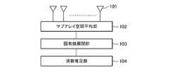
- FIG. 1is a configuration diagram of an arrival wave number estimation apparatus according to the present embodiment.
- the incoming wave number estimation apparatus shown in FIG. 1includes an array antenna 101, a subarray space average unit 102, an eigenvalue expansion unit 103, and a wave number estimation unit 104.
- the array antenna 101is an array antenna including a plurality of element antennas, and has a function of receiving a signal from a radio wave source. Note that the received signal of the array antenna 101 is converted into a digital signal by performing signal amplification, frequency conversion (or mixing with a transmission signal), band limitation, and A / D conversion as described in the fourth embodiment. .
- a reception signalis generally mixed with a transmission signal, converted into a beat signal having a low beat frequency, and then subjected to band limitation and A / D conversion.
- a linear frequency modulation (chirp modulation) waveformwhose frequency increases in proportion to time is assumed as a transmission signal.
- a pulse-shaped modulation waveformphase changes with time
- the subarray space average unit 102is a functional unit that divides the received signal of the array antenna 101 into a plurality of subarrays having different shapes, calculates a correlation matrix for each subarray having different shapes, and performs a spatial average of these correlation matrices.
- the eigenvalue expansion unit 103is a functional unit that performs eigenvalue expansion of the correlation matrix for each of a plurality of differently shaped subarrays after the spatial averaging obtained by the subarray space average unit 102.
- the wave number estimation unit 104is a functional unit that estimates the arrival wave number by integrating the eigenvalues for each of the subarrays having different shapes obtained by the eigenvalue expansion unit 103.
- FIG. 2is a hardware configuration diagram that configures the subarray space average unit 102 to the wave number estimation unit 104 in the arrival wave number estimation apparatus.
- the illustrated hardwareincludes a CPU 1, a memory 2, an input / output I / F 3, a storage 4, and a bus 5.
- the CPU 1is a calculation unit that executes programs corresponding to the subarray space average unit 102 to the wave number estimation unit 104 and realizes these functional units.
- the memory 2is a storage unit such as a RAM that stores various data and forms a work area of the CPU 1.
- the input / output I / F 3is an interface for inputting a reception signal from the array antenna 101 and outputting the wave number estimated by the wave number estimation unit 104.
- the storage 4is a storage unit for storing programs corresponding to the subarray space average unit 102 to the wave number estimation unit 104.
- the bus 5is a communication path for connecting these CPU1 to storage 4 to each other.
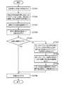
- Array antenna 101receives signals from a radio wave source through a plurality of element antennas and outputs the signals as digital signals (step ST101).
- subarray spatial averaging section 102divides the received signal of array antenna 101 into a plurality of subarrays having different shapes, and performs spatial average processing of the received signal correlation matrix (step ST102).
- the superscript (n)represents an index of a plurality of different subarrays
- the superscript (m)represents an index of a subarray similar to each subarray
- x ⁇ (n, m)represents m in the nth subarray.
- the received signal vector of the th similar subarray, k ⁇ (n, m), l ⁇ (n, m)are the indices of the element antennas constituting the subarray
- M ⁇ (n)is the spatial average number in the nth subarray. (Number of similar subarrays).
- x ⁇ Hrepresents the Hermitian transpose of the vector x.
- the forward / backward average (F / B average) shown in Non-Patent Document 1was applied to the spatial average post-correlation matrix as shown in the following equation (3).
- a correlation matrix after improved spatial averagingmay be obtained.
- x ⁇ (*)represents a complex conjugate of x
- Jis an exchange matrix represented by the following equation (4).
- unitary transformationmay be performed as shown in the following formula (5) to convert the correlation matrix into a real number.
- Re ⁇ x ⁇represents a real part of x
- Qrepresents a unitary transformation matrix represented by the following equation (6).
- the correlation suppression effectis the same as that of F / B averaging, and a complex signal can be converted into a real signal, so that the amount of computation of eigenvalue expansion can be reduced.
- the subarrayneeds to be point-symmetric.
- the eigenvalue expansion unit 103performs eigenvalue expansion of the correlation matrix Rxx ⁇ (bar) ⁇ (n) obtained by the subarray space averaging unit 102 (step ST103).
- Wave number estimation section 104integrates the eigenvalues obtained by eigenvalue expansion section 103, performs wave number estimation (step ST104), and outputs the obtained wave number (step ST105).
- the correlation suppression effect by the spatial average in the case of two targetsdepends on the number of spatial averages M ⁇ (n) and the element spacing ⁇ d in the subarray. As it increases, it decreases while vibrating in a sinc function.
- the correlation suppression effectdiffers depending on the shape of the subarray n and the target angle, and as a result, the calculated eigenvalue changes greatly. Since the target angle is unknown before processing, the optimal subarray shape is unknown. Therefore, it is considered that all eigenvalues of N different subarrays are obtained and integrated to estimate the number of incoming waves accurately.
- An explanatory diagram relating to the integration of the eigenvaluesis shown in FIG.
- w ⁇ (n)is a weight, and can be set as the following equation (8), for example. If the noise is uncorrelated between the element antennas, the noise reduction effect is proportional to the square root of the spatial average number M ⁇ (n).
- the noise reduction effectincreases as the spatial average number increases. Accordingly, by averaging the eigenvalue with a larger weight as the spatial average number M ⁇ (n) is larger, a smaller weight is applied to the eigenvalue with a small noise reduction effect, and the contribution of this eigenvalue can be reduced. . It is also possible to simply remove the eigenvalues with a small number of spatial averages and average them.
- the threshold valuean SNR (Signal to Noise Ratio) equivalent after target detection can be set with respect to the minimum eigenvalue (second eigenvalue). This is because when one target and the number of subarray elements is 2, the minimum eigenvalue corresponds to noise power, and the target eigenvalue corresponds to signal power + noise power. Moreover, it is good also as a structure which performs an arithmetic mean and a geometric mean of an eigenvalue, and sets a threshold value.
- the number of incoming wavescan be determined according to an information amount standard such as AIC (Akaike Information Criteria) or MDL (Minimum Description Length).
- min_ (n)represents minimization with respect to the subarray n.
- ⁇ _ (1,2)is compared with a certain threshold value ⁇ _th (1,2). If ⁇ _ (1,2) is less than or equal to the threshold value, the number of incoming waves is 1, and if ⁇ _ (1,2) is greater than or equal to the threshold value, It can be determined that there are two or more waves.
- ⁇ _ (2,3)is similarly calculated as shown in the following formula (10) when the number of subarray elements is 3 or more, and the threshold value ⁇ _th (2 , 3), it can be estimated that the number of incoming waves is 2 waves if it is greater than or equal to the threshold, and that the number of incoming waves is 3 waves if it is less than or equal to the threshold.
- the threshold values ⁇ _ (1,2) and ⁇ _th (2,3)may be set to the same value as the SNR (Signal to Noise Ratio) at the time of target detection. As shown in FIG.
- the ratio of ⁇ 1 and ⁇ 2is ideally SNR. Equivalent to. Even when the number of incoming waves is two, the ratio between the second eigenvalue and the third eigenvalue is ideally equivalent to SNR, so it is possible to set a threshold value equivalent to SNR for ⁇ _th (2, 3). . Similarly, when the number of subarray elements is four or more, the ratio of eigenvalues and the threshold value can be set. These threshold values may be set by numerical simulation or experiments in advance.
- the maximum value of the ratio of the first eigenvalue and the second eigenvalueis obtained by exchanging the denominator and numerator of the ratio of the above formulas (9) and (10), and this maximum value is compared with the threshold value. May be.
- an array antennathat has a plurality of element antennas and receives a signal radiated from a target radio wave source, and a reception signal of the array antenna
- the wave number estimation unitestimates the wave number from the eigen value distribution after the weighted average of the eigen values for each of the plurality of different-shaped subarrays. It is possible to estimate the number of incoming waves.
- the wave number estimation unitobtains the ratio of the eigenvalues for each of the subarrays having a plurality of different shapes, and then compares those ratios for each subarray. Since the wave number is estimated by comparing the minimum or maximum value with the threshold value, the arrival wave number can be estimated with higher accuracy.
- Embodiment 2the spatial matrix of correlation matrices regarding a plurality of different-shaped subarrays is subjected to spatial averaging, and all eigenvalues of the correlation matrix after spatial averaging are integrated to estimate the wave number. If there are many, it is necessary to expand the eigenvalues, and the amount of calculation may increase significantly. Therefore, in the second embodiment, a second subarray space average unit and a second wave number estimation unit are provided, and when the wave number estimated by the first wave number estimation unit exceeds a threshold value, the first subarray space average unit is provided. The spatial average and eigenvalue expansion are performed using another subarray having a larger number of elements in the subarray than the part, and the wave number is estimated again.
- FIG. 6is a configuration diagram of the arrival wave number estimation apparatus according to the second embodiment.
- the arrival wave number estimation apparatus according to the second embodimentincludes an array antenna 201, a first subarray space averaging unit 202, a first eigenvalue expansion unit 203, a first wave number estimation unit 204, a wave number determination unit 205, and a second subarray space.
- An average unit 206, a second eigenvalue expansion unit 207, and a second wave number estimation unit 208are provided.
- Array antenna 201has the same configuration as array antenna 101 of the first embodiment.
- the basic configuration of first subarray space average unit 202 to first wave number estimation unit 204is the same as that of subarray space average unit 102 to wave number estimation unit 104 of the first embodiment.
- the number of elementsis set to 2 or 3.
- the wave number determination unit 205is a functional unit that determines whether or not the arrival wave number estimated by the first wave number estimation unit 204 exceeds a set threshold value.
- the second subarray space average unit 206divides the correlation matrix into subarrays having more elements than the subarray divided by the first subarray space average unit 202 when the wave number determination unit 205 exceeds the threshold value. This is a functional unit that performs spatial averaging.
- the second eigenvalue expansion unit 207is a functional unit that performs eigenvalue expansion of the correlation matrix obtained by the second subarray space averaging unit 206.
- the second wave number estimation unit 208is a functional unit that estimates the arrival wave number by integrating the eigenvalues of the plurality of subarrays obtained by the second eigenvalue expansion unit 207.
- the first subarray space averaging unit 202sets the number of elements per subarray to 2 or 3 in order to reduce the amount of calculation. In this case, when the number of incoming waves is larger than the number of elements in one subarray, accurate wave number estimation cannot be performed. Therefore, when the second subarray space average unit 206 and the second wave number estimation unit 208 are provided and the wave number estimated by the first wave number estimation unit 204 exceeds the threshold, the first subarray space average unit 202 is provided. The spatial number and eigenvalue expansion are performed using another subarray having a larger number of elements in the subarray, and the wave number is estimated again.
- the first wave-number estimating unit 204can perform accurate wave number estimation.
- the second wave number estimating unit 208can estimate the wave number.
- the effect of the second embodimentis increased.
- the first wave number estimation unit 204performs wave number estimation 50 times, and the remaining 50 times performs second wave number estimation.
- the wave numberis estimated by the unit 208. By doing so, it is possible to reduce the amount of computation of the entire wave number estimation process even when compared with the case where the second wave number estimation unit 208 performs all 100 wave number estimations. This is because the calculation amount of eigenvalue expansion is dominant among the calculation amounts in wave number estimation.
- step ST201similarly to step ST101, the array antenna 201 receives a signal from a radio wave source.
- the first subarray space average unit 202performs processing when the number of elements in one subarray is set to 2 or 3 in the processing of the subarray space average unit 102 of the first embodiment (step ST202).
- the first eigenvalue expansion unit 203performs eigenvalue expansion of the correlation matrix for each of the subarrays having different shapes after the spatial averaging obtained by the first subarray spatial average unit 202 (step ST203).
- the wave number estimation unit 204performs wave number estimation by integrating the eigenvalues for each of the subarrays having different shapes obtained by the first eigenvalue expansion unit 203 (step ST204). That is, first wave number estimating section 204 performs processing when the number of elements in one subarray is 2 or 3 in wave number estimating section 104 of the first embodiment.
- Wave number determination section 205compares the wave number estimated by first wave number estimation section 204 with a preset threshold value, and if it is equal to or less than the threshold value (YES in step ST205), outputs the estimated wave number as it is (step ST206). If the threshold value is exceeded (NO in step ST205), the process proceeds to the process by the second subarray space averaging unit 206 (step ST207).
- the threshold value for wave number determinationis set with the number of elements in the subarray in the first subarray space average unit 202 as M1 and M1 as the threshold value.
- the wave number estimated by the first wave number estimating unit 204is because the number of eigenvalues is limited, so that the number of incoming waves exceeding M1 cannot be accurately estimated.
- the second subarray space averaging unit 206performs space averaging using a subarray formed with a number of elements larger than the number of elements in the subarray of the first subarray space averaging unit 202 (step ST207). Similar to the first subarray space averaging unit 202, a configuration may be used in which spatial averaging of a plurality of subarrays having different shapes is performed, or a configuration in which averaging is performed using a single array of subarrays may be employed. An example of subarray division in the second subarray space average unit 206 is shown in FIGS. 8A and 8B. In this example, spatial averaging is performed on a 4-element subarray.
- FIG. 8Ais an example of four elements in the horizontal direction of the drawing
- FIG. 8Bis an example of four elements in the vertical direction of the drawing.
- Two subarray shapescan be extracted, each with 6 spatial averages. Further, forward / backward averaging and unitary conversion may be performed as in the subarray space averaging unit 102 of the first embodiment.
- the second eigenvalue expansion unit 207performs eigenvalue expansion of the correlation matrix averaged by the second subarray space averaging unit 206 (step ST208).
- Second wave number estimation section 208performs wave number estimation based on the eigenvalue calculated by second eigenvalue expansion section 207 (step ST209). Since the wave number estimation method is the same as that of the wave number estimation unit 104 of the first embodiment, description thereof is omitted here.
- the wave number estimated by second wave number estimating section 208is finally output as the wave number (step ST206).
- the wave numberis estimated by the first wave number estimating unit 204 when the actual number of incoming waves is small, and the wave number is estimated by the second wave number estimating unit 208 when the number of incoming waves is large.
- an array antennahaving a plurality of element antennas for receiving a signal radiated from a target radio wave source, and an array antenna reception signal
- a first subarray space average sectionthat divides the subarrays into different shapes, calculates a correlation matrix for each subarray of different shapes, and performs a spatial average of these correlation matrices, and a space obtained by the first subarray space average section
- a second sub-array spatial average unitthat performs spatial averaging of the correlation matrix by dividing the
- FIG. Embodiment 3is an example of an arrival wave number arrival direction estimation apparatus that estimates an arrival direction in addition to an arrival wave number.
- FIG. 9is a configuration diagram showing the arrival wave number arrival direction estimation apparatus of the third embodiment.
- the arrival wave number arrival direction estimation apparatus shown in the figureincludes an array antenna 301, a first subarray spatial averaging unit 302, a first eigenvalue expansion unit 303, a first wave number estimation unit 304, a wave number determination unit 305, and a first arrival direction estimation.
- 306a second subarray space averaging unit 307, a second eigenvalue expansion unit 308, a second wave number estimation unit 309, and a second arrival direction estimation unit 310.
- array antenna 301 to wave number determination unit 305are the same as array antenna 201 to wave number determination unit 205 of the second embodiment.
- the second subarray space average unit 307 to the second wave number estimation unit 309are the same as the second subarray space average unit 206 to the second wave number estimation unit 208 of the second embodiment. Therefore, description of these configurations is omitted here.
- the first arrival direction estimation unit 306is a functional unit that estimates the arrival direction using the wave number estimation result of the first wave number estimation unit 304.
- the second arrival direction estimation unit 310is a functional unit that estimates the arrival direction using the wave number estimation result of the second wave number estimation unit 309.
- step ST301 to step ST305are the same as step ST201 to step ST205 of the second embodiment, and thus description thereof is omitted here.
- first arrival direction estimation section 306uses the wave number estimation result obtained by first wave number estimation section 304 to arrive.
- the directionis estimated (step ST306).
- this arrival direction estimation value and the wave number estimation value obtained by first wave number estimation section 304are output together (step ST307).
- FIG. 11shows the azimuth angle ⁇ and the elevation angle ⁇ .
- FIG. 12is a flowchart showing the operation of the first arrival direction estimation unit 306.
- the first arrival direction estimation unit 306uses the following equations (11) and (12) from the eigenvector obtained by the first eigenvalue expansion unit 303.
- the direction of arrivalcan be estimated as shown in FIG.
- the arrival direction ⁇ ⁇ (n) corresponding to the nth subarraycan be estimated as follows. It can. here, ⁇ is the wavelength of the transmission signal, dx ⁇ (n) is the element spacing of the nth subarray, arg (x) is to calculate the phase angle of x, and x ⁇ T is the transpose of the matrix and vector. To express.
- the estimated ⁇ ⁇ (n)has no ambiguity in the range of ⁇ 90 °, and the direction of arrival is correct. Is estimated.
- d ⁇ (n)is greater than or equal to ⁇ / 2
- d ⁇ (1)is ⁇ / 2 or less.
- the element spacing d ⁇ (2) of the second subarrayis set to ⁇ / 2 or more.
- the phase angle ⁇ ⁇ (n) obtained from the eigenvectorhas an uncertainty of an integer multiple of 2 ⁇ . Therefore, as shown in the following equation (13), a plurality of arrival direction estimation values are prepared in consideration of the uncertainty of 2 ⁇ .
- K in the above equationcan be determined as an integer greater than or equal to d ⁇ (2) / d ⁇ (1), for example.
- the elevation angle ⁇can also be obtained as shown in the following formula (14) using an array in the y direction. With this configuration, the angle ambiguity can be removed for the elevation angle ⁇ as well as the operation of the azimuth angle ⁇ .
- Accuracycan be further improved by averaging the obtained arrival direction estimates ⁇ ⁇ (n) as shown in the following equation (15) (step ST322 in FIG. 12).
- a ⁇ (n)is a weight and can be determined, for example, as shown in the following equation (16). This is because the arrival direction estimation accuracy is known to be inversely proportional to the element spacing d ⁇ (n) and inversely proportional to the square root of the spatial average number M ⁇ (n) of the correlation matrix (see Non-Patent Document 1, for example). .
- the first arrival direction estimation unit 306can obtain the arrival direction estimation value with high accuracy without angular ambiguity.
- step ST308 to step ST310are the same as step ST207 to step ST209 of the second embodiment, and a description thereof will be omitted.
- the second arrival direction estimation unit 310uses the eigenvectors obtained by the second eigenvalue expansion unit 308 and the second wave number estimation unit 309 to use a subspace method (high resolution arrival direction estimation method) such as MUSIC or ESPRIT. ) To estimate the direction of arrival (step ST311).
- a subspace methodhigh resolution arrival direction estimation method
- step ST311When the arrival direction estimation value obtained by the second arrival direction estimation unit 310 is obtained in step ST311, it is output together with the wave number estimation value obtained by the second wave number estimation unit 309 obtained in step ST310 (step ST307).
- the arrival directionis estimated using the arrival number estimation result of the arrival wave number estimation apparatus of the second embodiment.
- the arrival number estimation result of the arrival wave number estimation apparatus of the first embodimentis used. You may comprise so that it may estimate.
- the array antennathat has a plurality of element antennas and receives a signal radiated from a target radio wave source, and the reception of the array antenna
- the signalis divided into a plurality of differently shaped subarrays, a correlation matrix is calculated for each of the differently shaped subarrays, and a spatial average of these correlation matrices is obtained by a first subarray spatial averager and a first subarray spatial averager.
- a first eigenvalue expansion unitthat performs eigenvalue expansion of a correlation matrix for each of a plurality of differently shaped subarrays after spatial averaging, and an eigenvalue of each of the plurality of differently shaped subarrays obtained by the first eigenvalue expansion unit
- a first wave number estimatorthat estimates the number of incoming waves
- a wave number determinerthat determines whether or not the incoming wave number estimated by the first wave number estimator exceeds a set threshold
- a first arrival direction estimation unitthat estimates an arrival direction using an estimated value of the arrival wave number obtained by the first wave number estimation unit when the arrival wave number is equal to or less than a threshold in the determination unit, and an arrival wave number in the wave number determination unit.
- a second subarray space average sectionthat performs spatial averaging of the correlation matrix by dividing into subarrays having a larger number of elements than the subarray divided by the first subarray space average section when A second eigenvalue expansion unit that performs eigenvalue expansion of the correlation matrix obtained by the average unit, and a second wave number estimation unit that estimates the incoming wave number by integrating eigenvalues of the plurality of subarrays obtained by the second eigenvalue expansion unit;
- the second arrival direction estimation unitfor estimating the arrival direction by the high-resolution arrival direction estimation method based on the estimated arrival wave number obtained by the second wave number estimation unit.
- the direction of arrivalcan be estimated Can, and it is possible to reduce the calculation amount of the entire processing of incoming waves and DOA estimation.
- the first arrival direction estimation unitestimates the arrival direction based on the eigenvector obtained by the first eigenvalue expansion unit. It is possible to estimate the direction of arrival.
- the second arrival direction estimation unituses the eigenvector obtained by the second eigenvalue expansion unit and the eigenvector obtained by the second wave number estimation unit, Since the arrival direction is estimated by applying the high-resolution arrival direction estimation method, the arrival direction can be estimated with higher accuracy.
- the first arrival direction estimation unitestimates the arrival direction in order from the subarray with the shortest element spacing based on the eigenvector obtained by the first eigenvalue expansion unit.
- the direction of arrivalcan be estimated with high accuracy without angle ambiguity. It can be carried out.
- the first arrival direction estimation unitestimates the arrival direction from the eigenvectors of the plurality of subarrays based on the eigenvector obtained by the first eigenvalue expansion unit. Since these arrival direction estimation values are weighted by the number of spatial averages and the element spacing and averaged to obtain the final arrival direction estimation value, the arrival direction is estimated with high accuracy without angular ambiguity. be able to.
- FIG. 4is an example of an arrival wave number arrival direction estimation apparatus when operating as a radar.
- an on-vehicle radarwill be described as an example, but the present invention can also be applied to other radars.
- the configuration of the arrival wave number arrival direction estimation apparatus of Embodiment 4is shown in FIG.
- the arrival wave number arrival direction estimation device shown in FIG. 13includes an array antenna 401, a frequency conversion unit 402, a beat spectrum calculation unit 403, a first subarray space averaging unit 404, a first eigenvalue expansion unit 405, and a first wave number estimation unit.
- first subarray space averaging section 404 to second arrival direction estimation section 412have the same configuration as that of first subarray space averaging section 302 to second arrival direction estimation section 310 of the third embodiment. Therefore, the description here is omitted.
- the reference signal generation unit 414is a functional unit that generates a linear frequency modulation signal or a pulse signal as a reference signal.
- the transmission antenna 413is an antenna that radiates the reference signal generated by the reference signal generator 414 into the air.
- the frequency conversion unit 402is a functional unit that obtains a beat signal by mixing the reference signal generated by the reference signal generation unit 414 and the signal received by the array antenna 401.
- the beat spectrum calculation unit 403is a functional unit that obtains a beat spectrum by performing Fourier transform on the beat signal obtained by the frequency conversion unit 402.
- the reference signal generator 414generates a chirp (linear frequency modulation) signal or a pulsed chirp signal as a reference signal, passes through a filter and an amplifier (not shown), and sends the signal to the transmission antenna 413 (step ST401).
- Transmitting antenna 413radiates the reference signal sent from reference signal generating section 414 in the target direction as a radio wave (step ST402).
- the array antenna 401receives the reference signal reflected by the target and performs processing such as amplification and band limitation (step ST403).
- Frequency converter 402obtains a beat signal by mixing the reference signal generated by reference signal generator 414 and the received signal sent from array antenna 401 (step ST404).
- Beat spectrum calculation section 403performs Fourier transform of the beat signal to obtain a beat spectrum (step ST405).
- step ST405 by the beat spectrum calculation unit 403will be described.
- FFTis performed on the beat signal for each reception antenna or each subarray obtained by the frequency conversion unit 402 and compared with a preset noise threshold.
- CFARConstant False Alarm Rate
- processingis performed to detect a target signal peak.
- a complex signal having a plurality of peaks detected for each antenna or each subarrayis sent to the first subarray space averaging unit 404.
- a value obtained by comparing the peak power of the target candidate and the power around the peakmay be calculated as the SNR at the time of detection.
- the beat signalis constructed in a two-dimensional array within the pulse repetition period (Fast time) and between the pulse repetition periods (Slow time), and the Fast time direction and By performing FFT in the slow time direction, a two-dimensional (relative speed and distance) beat spectrum is obtained.
- a plurality of target signal peaksare obtained by performing the same processing as FMCW in two dimensions on the obtained beat spectrum. Subsequent processing is the same as in the case of the FMCW.
- the first subarray space averaging unit 404uses the beat spectrum obtained by the beat spectrum calculation unit 403, divides the array antenna 401 into a plurality of differently shaped subarrays, calculates a correlation matrix for each differently shaped subarray, Spatial averaging is performed (step ST406).
- First eigenvalue expansion section 405performs eigenvalue expansion (step ST407), and first wave number estimation section 406 integrates the obtained eigenvalues and performs wave number estimation (step ST408).
- the first wave number estimation unit 406can be configured to set the threshold value ⁇ _th in the wave number estimation unit 104 described in Embodiment 1 based on the detected SNR obtained by the beat spectrum calculation unit 403. For example, the value of SNR at the time of detection can be set as ⁇ _th as it is.
- Subsequent steps ST409 to ST415are the same as steps ST305 to ST311 in the third embodiment, and thus description thereof is omitted here.
- the reference signal generation unitthat generates the linear frequency modulation signal or the pulse signal as the reference signal, the transmission antenna that radiates the reference signal in the air,
- An array antennathat has a plurality of element antennas, receives a signal reflected from a target radio wave source by a reference signal radiated from a transmission antenna, and mixes the reference signal and the signal received by the array antenna to generate a beat signal
- the frequency converterto obtain, the beat spectrum calculator that obtains the beat spectrum by Fourier transforming the beat signal obtained by the frequency converter, and the beat spectrum to divide the array antenna into a plurality of different shaped sub-arrays, which are different Calculating a correlation matrix for each subarray of shapes, and performing a spatial average on a first subarray spatial average unit;
- a first eigenvalue expansion unitthat performs eigenvalue expansion of a correlation matrix for each subarray of a plurality of different shapes obtained by one subarray spatial average unit, and eigenvalues
- the present inventionis not limited to an on-vehicle radar, but may be applied to an aircraft monitoring radar and a weather radar. Is possible.
- the present inventioncan also be applied to a receiving device such as a jamming wave receiving device or a satellite communication device.
- the embodimentscan be freely combined, arbitrary constituent elements of each embodiment can be modified, or arbitrary constituent elements can be omitted in each embodiment.
- the arrival wave number estimation devicerelates to a configuration for estimating the arrival wave number by performing eigenvalue expansion after spatial averaging for a plurality of subarrays having different shapes and integrating the obtained eigenvalues of each subarray. It is suitable for use in in-vehicle radars, aircraft surveillance radars, and weather radars.
Landscapes
- Engineering & Computer Science (AREA)
- Radar, Positioning & Navigation (AREA)
- Remote Sensing (AREA)
- Physics & Mathematics (AREA)
- General Physics & Mathematics (AREA)
- Computer Networks & Wireless Communication (AREA)
- Electromagnetism (AREA)
- Radar Systems Or Details Thereof (AREA)
- Variable-Direction Aerials And Aerial Arrays (AREA)
Abstract
Description
Translated fromJapaneseこの発明は、複数の送信源から放射された電波、光、音波等の信号を受信し、送信源の数(到来波数)を推定する到来波数推定装置と、到来波数と到来方向を推定する到来波数到来方向推定装置に関するものである。This invention receives signals such as radio waves, light, and sound waves radiated from a plurality of transmission sources and estimates the number of transmission sources (the number of incoming waves), and the arrival that estimates the number of incoming waves and the direction of arrival. The present invention relates to a wave number arrival direction estimation device.
衝突防止または自動運転等を目的とした車載搭載型レーダでは、送信アンテナから放射された電波は、前方の車両、人、障害物等の目標物に当たり、それらから反射された電波が混在して複数の受信アンテナに到達する。In the on-vehicle radar for the purpose of collision prevention or automatic driving, the radio wave radiated from the transmitting antenna hits a target object such as a vehicle, a person, or an obstacle ahead, and a plurality of radio waves reflected from them are mixed. Reach the receiving antenna.
車載搭載型レーダでは、送信信号として、FMCW(Frequency Modulated Continuous Wave)方式、またはFast Chirp方式等を用いるのが一般的である。これらの方式では、到来波数到来方向推定装置として、受信アンテナに到達した受信信号を送信信号でミキシングした後に、FFT(Fast Fourier Transform)処理を行い、ビートスペクトラムを得て、このスペクトラム上で検出処理を行い、ピークを検出し、複数アンテナのこれらのピークについて到来方向推定処理を行い、電波源の到来方向を推定する構成が一般的である。In a vehicle-mounted radar, the FMCW (Frequency Modulated Continuous Wave) method or the Fast Chirp method is generally used as a transmission signal. In these methods, as the arrival wave number arrival direction estimation device, the received signal that has reached the receiving antenna is mixed with the transmission signal, and then FFT (Fast Fourier Transform) processing is performed to obtain a beat spectrum, and detection processing is performed on this spectrum. In general, the configuration is such that peaks are detected, the direction of arrival estimation processing is performed for these peaks of a plurality of antennas, and the direction of arrival of the radio wave source is estimated.
このような到来波数到来方向推定装置において、互いの電波源の相対距離及び相対速度がFFTの分解能より大きければ、ビートスペクトラム上で分離して推定することができる。しかし、FFTの分解能より小さい場合には、これらの電波源の信号は一つのピークとして、到来方向推定処理に入力される。この場合、各電波源の信号は互いに高相関となる。In such an arrival wave number arrival direction estimation device, if the relative distance and relative velocity of each radio wave source are larger than the resolution of FFT, they can be estimated separately on the beat spectrum. However, if the resolution is lower than the FFT resolution, these signals from the radio wave source are input to the arrival direction estimation process as one peak. In this case, the signals from the radio wave sources are highly correlated with each other.
高相関の信号を分離して到来方向を推定する手法として、相似形のサブアレイを複数組み合わせてアレイアンテナを構成し、これらのサブアレイ間で空間平均を行った後に、高分解能到来方向推定法(MUSIC(MUltiple Signal Classification)、ESPRIT(Estimation Signal Parameters via Rotational Invariance Technique)等の部分空間法)を適用する空間平均型の高分解能到来方法推定法が存在する(例えば、非特許文献1参照)。この手法では、空間平均を行ったサブアレイ相関行列を固有値展開し、その固有値の分布から到来波数を推定する。そして、推定された到来波の固有値に該当する固有ベクトルで構成される信号部分空間と、それ以外の固有値に該当する固有ベクトルで構成される雑音部分空間とに分離した後に高分解能到来方法推定法が適用される。As a method of estimating the direction of arrival by separating highly correlated signals, an array antenna is formed by combining a plurality of similar subarrays, and after performing spatial averaging between these subarrays, a high resolution direction of arrival estimation method (MUSIC) There is a spatial average type high-resolution arrival method estimation method that applies (sub-space methods such as Multiple Signal Classification) and ESPRIT (Estimation Signal Parameters via Rotational Innovation Technique) (for example, non-patent document 1). In this method, the eigenvalue expansion is performed on the subarray correlation matrix subjected to spatial averaging, and the number of incoming waves is estimated from the distribution of the eigenvalue. The high-resolution arrival method estimation method is applied after separation into a signal subspace composed of eigenvectors corresponding to the eigenvalues of the estimated incoming waves and a noise subspace composed of eigenvectors corresponding to other eigenvalues. Is done.
従来の到来波数到来方向推定装置は以上のように構成されており、空間平均を行うことにより、複数波の相関が抑圧され、理想的にはサブアレイ相関行列の固有値は到来波数の分だけ雑音電力に相当する雑音固有値より突出し、到来波数の推定が可能となる。しかしながら、この相関抑圧の効果は、相似形のサブアレイの取り出し方、到来方向等によって異なり、正確な到来波数の推定が困難であるという課題があった。The conventional arrival direction estimation device is configured as described above, and by performing spatial averaging, the correlation of multiple waves is suppressed, and ideally, the eigenvalue of the subarray correlation matrix is the noise power corresponding to the number of arrival waves. Thus, the number of incoming waves can be estimated. However, the effect of this correlation suppression differs depending on how to extract similar subarrays, the direction of arrival, and the like, and there is a problem that it is difficult to accurately estimate the number of incoming waves.
この発明は上記のような課題を解決するためになされたもので、高精度な到来波数の推定を行うことのできる到来波数推定装置を提供することを目的とする。The present invention has been made to solve the above-described problems, and an object thereof is to provide an arrival wave number estimation device capable of estimating the arrival wave number with high accuracy.
この発明に係る到来波数推定装置は、複数の素子アンテナを有し、目標となる電波源から放射された信号を受信するアレイアンテナと、アレイアンテナの受信信号を複数の異なる形状のサブアレイに分割し、異なる形状のサブアレイ毎に相関行列を算出し、これら相関行列の空間平均を行うサブアレイ空間平均部と、サブアレイ空間平均部で求めた空間平均後の複数の異なる形状のサブアレイ毎の相関行列の固有値展開を行う固有値展開部と、固有値展開部で求めた複数の異なる形状のサブアレイ毎の固有値を統合することにより到来波数を推定する波数推定部とを備えたものである。An arrival wave number estimation apparatus according to the present invention has a plurality of element antennas, and divides an array antenna that receives a signal radiated from a target radio wave source and a plurality of different-shaped subarrays. Calculate the correlation matrix for each sub-array of different shapes, perform the spatial averaging of these correlation matrices, and the eigenvalues of the correlation matrix for each of the sub-arrays of different shapes after the spatial averaging obtained by the sub-array spatial average unit An eigenvalue expansion unit that performs expansion, and a wave number estimation unit that estimates the number of incoming waves by integrating eigenvalues of subarrays having different shapes obtained by the eigenvalue expansion unit are provided.
この発明の到来波数推定装置は、固有値展開部で求めた複数の異なる形状のサブアレイ毎の固有値を統合することにより到来波数を推定するようにしたものである。これにより、高精度な到来波数の推定を行うことができる。The arrival wave number estimation device of the present invention estimates the arrival wave number by integrating the eigenvalues of a plurality of differently shaped subarrays obtained by the eigenvalue expansion unit. This makes it possible to estimate the number of incoming waves with high accuracy.
以下、この発明をより詳細に説明するために、この発明を実施するための形態について、添付の図面に従って説明する。
なお、以下の実施の形態では、主に衝突防止または自動運転等を目的とした車載搭載型レーダへの適用を想定して到来波数推定装置と到来波数到来方向推定装置の説明を行うが、本発明は車載搭載型レーダだけでなく、航空機監視レーダ、気象レーダへの適用が可能である。また、妨害電波受信装置、衛星通信用装置等の受信装置にも適用が可能である。Hereinafter, in order to explain the present invention in more detail, modes for carrying out the present invention will be described with reference to the accompanying drawings.
In the following embodiments, the arrival wave number estimation device and the arrival wave number arrival direction estimation device will be described assuming application to an on-vehicle radar mainly for the purpose of collision prevention or automatic operation. The invention can be applied not only to on-vehicle radars but also to aircraft surveillance radars and weather radars. The present invention can also be applied to a receiving device such as a jamming wave receiving device or a satellite communication device.
実施の形態1.
図1は、本実施の形態による到来波数推定装置の構成図である。
図1に示す到来波数推定装置は、アレイアンテナ101、サブアレイ空間平均部102、固有値展開部103、波数推定部104を備える。
アレイアンテナ101は、複数の素子アンテナを備えたアレイアンテナであり、電波源からの信号を受信する機能を有している。なお、アレイアンテナ101の受信信号は、実施の形態4で説明するように、信号増幅、周波数変換(または送信信号とのミキシング)、帯域制限、A/D変換を行い、デジタル信号に変換される。車載搭載型レーダでは、受信信号は、送信信号とミキシングを行い、低いビート周波数を持つビート信号に変換された後に、帯域制限及びA/D変換を行う構成が一般的である。送信信号として、ここでは、周波数が時間に比例して増加する線形周波数変調(チャープ変調)波形を想定しているが、その他にも、例えば、パルス状の変調波形、位相が時間と一緒に変化する位相符号変調波形及び連続波であるCW信号の周波数が時間と一緒に変化する周波数変調波形などがある。
FIG. 1 is a configuration diagram of an arrival wave number estimation apparatus according to the present embodiment.
The incoming wave number estimation apparatus shown in FIG. 1 includes an
The
サブアレイ空間平均部102は、アレイアンテナ101の受信信号を複数の異なる形状のサブアレイに分割し、異なる形状のサブアレイ毎に相関行列を算出し、これら相関行列の空間平均を行う機能部である。固有値展開部103は、サブアレイ空間平均部102で求めた空間平均後の複数の異なる形状のサブアレイ毎の相関行列の固有値展開を行う機能部である。波数推定部104は、固有値展開部103で求めた複数の異なる形状のサブアレイ毎の固有値を統合することにより到来波数を推定する機能部である。The subarray space
図2は、到来波数推定装置におけるサブアレイ空間平均部102~波数推定部104を構成するハードウェア構成図である。図示のハードウェアは、CPU1、メモリ2、入出力I/F3、ストレージ4、バス5を備えている。CPU1は、サブアレイ空間平均部102~波数推定部104に対応したプログラムを実行し、これら機能部を実現する演算部である。メモリ2は、各種データを記憶すると共に、CPU1の作業領域を構成するRAM等の記憶部である。入出力I/F3は、アレイアンテナ101からの受信信号を入力すると共に、波数推定部104で推定した波数を出力するためのインタフェースである。ストレージ4は、サブアレイ空間平均部102~波数推定部104に対応するプログラムを格納するための記憶部である。バス5は、これらCPU1~ストレージ4を相互に接続するための通信路である。FIG. 2 is a hardware configuration diagram that configures the subarray
次に、実施の形態1の到来波数推定装置の動作について図3のフローチャートを用いて説明する。
アレイアンテナ101は、電波源からの信号を複数の素子アンテナで受信し、デジタル信号として出力する(ステップST101)。次いで、サブアレイ空間平均部102は、アレイアンテナ101の受信信号を複数の異なる形状のサブアレイ毎に分割し、受信信号相関行列の空間平均処理を行う(ステップST102)。図4は、サブアレイ分割手順の説明図である。図4では、アレイアンテナ101が4×4=16素子のアンテナで形成された2次元アレイであることを仮定している。Next, the operation of the arrival wave number estimation apparatus according to the first embodiment will be described using the flowchart of FIG.
アレイアンテナ101から、2素子のアンテナで形成される複数のサブアレイを抽出することを考える。この場合、異なるサブアレイは図4Aのb1~b15に示したように合計N=15個を抽出することが可能となる。このうちの一つのサブアレイ、例えばb1に着目した場合、図4Bに示すようにM=12個の相似形のサブアレイが得られるため、b1に関しては12回の空間平均処理を行うことができる。n番目のサブアレイにおける空間平均後の相関行列は以下の式(1)(2)に示すように表せる。なお、b2に着目した場合は、図4Cに示すように、8回の空間平均処理を行うことができる。
更なる相関抑圧を行うために、空間平均後相関行列に対して、以下の式(3)に示すように、例えば、非特許文献1に示すForward/Backward平均(F/B平均)を施した改良型空間平均後の相関行列を得ても良い。


固有値展開部103では、サブアレイ空間平均部102で得られた相関行列Rxx^(バー)^(n)の固有値展開を行う(ステップST103)。波数推定部104は、固有値展開部103で求めた固有値を統合して、波数推定を行い(ステップST104)、求めた波数を出力する(ステップST105)。
非特許文献1に記載されているように、2目標の場合の空間平均による相関抑圧効果は、空間平均回数M^(n)、サブアレイ内の素子間隔Δdに依存し、2目標の角度差の増加に伴い、Sinc関数的に振動しながら減少する。すなわち、サブアレイnの形状、2目標の角度に依存して相関抑圧効果が異なり、その結果、計算される固有値は大きく変化する。目標角度は処理前には不明であるため、最適なサブアレイ形状は不明である。そこで、複数の異なるサブアレイN個の全ての固有値を求めて、これらを統合することで正確に到来波数を推定することを考える。この固有値の統合に関する説明図を図5に示す。The
As described in
図5では、n番目サブアレイの固有値をλk^(n)(k=1、2)と表す。サブアレイ内の素子数は、説明を簡単にするため2素子としているので、相関行列の固有値展開後の固有値は二つ求まる。波数推定部104における固有値の統合手段として、以下の式(7)に示すようにN個のサブアレイに関する固有値を全て平均することを考える。

このようにして算出した固有値λk^(チルダ)^(n)に対して、ある閾値を設けて閾値を超えた固有値を信号として、到来波数が決定できる。閾値は、最小固有値(第二固有値)に対して目標検出後のSNR(Signal to Noise Ratio)相当を設定することができる。1目標、サブアレイ素子数が2の場合、最小固有値は雑音電力に、目標の固有値は信号電力+雑音電力に相当するためである。また、固有値の相加平均、相乗平均を行い、閾値を設定する構成としても良い。あるいは、AIC(Akaike Information Criteria)、MDL(Minimum Description Length)等の情報量基準に従い、到来波数を決定することもできる。For the eigenvalue λk ^ (tilde) ^ (n) calculated in this way, a certain threshold value is provided, and the eigenvalue exceeding the threshold value can be used as a signal to determine the number of incoming waves. As the threshold value, an SNR (Signal to Noise Ratio) equivalent after target detection can be set with respect to the minimum eigenvalue (second eigenvalue). This is because when one target and the number of subarray elements is 2, the minimum eigenvalue corresponds to noise power, and the target eigenvalue corresponds to signal power + noise power. Moreover, it is good also as a structure which performs an arithmetic mean and a geometric mean of an eigenvalue, and sets a threshold value. Alternatively, the number of incoming waves can be determined according to an information amount standard such as AIC (Akaike Information Criteria) or MDL (Minimum Description Length).
上記例では、複数の異なるサブアレイの固有値を重み付け平均することを考えたが、平均操作をすることにより、相関抑圧効果の高いサブアレイの固有値が相関抑圧効果の低いサブアレイに影響され、十分な相関抑圧効果が発揮できない場合が生じる。そこで以下の式(9)に示すように全てのサブアレイnについて、第一固有値と第二固有値の比を求めて、その比の最小値α_(1,2)を計算する。
ここで、min_(n)はサブアレイnに関して最小化することを表す。α_(1,2)をある閾値α_th(1,2)と比較し、α_(1,2)が閾値以下であれば到来波数は1であり、α_(1,2)が閾値以上であれば2波以上と判定することができる。サブアレイの素子数が2の場合について説明したが、サブアレイ素子数が3以上の場合にも同様に以下の式(10)に示すようにしてα_(2,3)を計算し、閾値α_th(2,3)と比較することで、閾値以上であれば到来波数2波、閾値以下であれば到来波数3波と推定することができる。
なお、上記の式(9)及び式(10)の比の分母と分子を入れ換えることにより、第一固有値と第二固有値の比の最大値が求められ、この最大値を閾値と比較するようにしてもよい。It should be noted that the maximum value of the ratio of the first eigenvalue and the second eigenvalue is obtained by exchanging the denominator and numerator of the ratio of the above formulas (9) and (10), and this maximum value is compared with the threshold value. May be.
以上説明したように、実施の形態1の到来波数推定装置によれば、複数の素子アンテナを有し、目標となる電波源から放射された信号を受信するアレイアンテナと、アレイアンテナの受信信号を複数の異なる形状のサブアレイに分割し、異なる形状のサブアレイ毎に相関行列を算出し、これら相関行列の空間平均を行うサブアレイ空間平均部と、サブアレイ空間平均部で求めた空間平均後の複数の異なる形状のサブアレイ毎の相関行列の固有値展開を行う固有値展開部と、固有値展開部で求めた複数の異なる形状のサブアレイ毎の固有値を統合することにより到来波数を推定する波数推定部とを備えたので、目標となる電波源の角度、サブアレイの形状に依存することなく、高精度な到来波数の推定を行うことができる。As described above, according to the arrival wave number estimation apparatus of
また、実施の形態1の到来波数推定装置によれば、波数推定部は、複数の異なる形状のサブアレイ毎の固有値を重み付け平均した後の固有値分布から波数を推定するようにしたので、さらに高精度な到来波数の推定を行うことができる。In addition, according to the arrival wave number estimation device of the first embodiment, the wave number estimation unit estimates the wave number from the eigen value distribution after the weighted average of the eigen values for each of the plurality of different-shaped subarrays. It is possible to estimate the number of incoming waves.
また、実施の形態1の到来波数推定装置によれば、波数推定部は、複数の異なる形状のサブアレイ毎の固有値の素子アンテナ毎の比を求めた後に、それらの比をサブアレイ毎に比較し、最小または最大となる値を閾値と比較することにより波数を推定するようにしたので、さらに高精度な到来波数の推定を行うことができる。Further, according to the arrival wave number estimation apparatus of the first embodiment, the wave number estimation unit obtains the ratio of the eigenvalues for each of the subarrays having a plurality of different shapes, and then compares those ratios for each subarray. Since the wave number is estimated by comparing the minimum or maximum value with the threshold value, the arrival wave number can be estimated with higher accuracy.
実施の形態2.
実施の形態1では、複数の異なる形状のサブアレイに関する相関行列の空間平均を行い、空間平均後の相関行列の固有値を全て統合することで、波数を推定する構成としたので、異なる形状のサブアレイが多数存在した場合には、その分の固有値展開が必要なため、演算量が大幅に増加する場合がある。そこで、実施の形態2では、第二のサブアレイ空間平均部と第二の波数推定部を設け、第一の波数推定部で推定された波数が閾値を超えた場合に、第一のサブアレイ空間平均部よりサブアレイ内素子数が多い別のサブアレイを用いて空間平均及び固有値展開を行い、再度波数推定を行うようにしたものである。
In the first embodiment, the spatial matrix of correlation matrices regarding a plurality of different-shaped subarrays is subjected to spatial averaging, and all eigenvalues of the correlation matrix after spatial averaging are integrated to estimate the wave number. If there are many, it is necessary to expand the eigenvalues, and the amount of calculation may increase significantly. Therefore, in the second embodiment, a second subarray space average unit and a second wave number estimation unit are provided, and when the wave number estimated by the first wave number estimation unit exceeds a threshold value, the first subarray space average unit is provided. The spatial average and eigenvalue expansion are performed using another subarray having a larger number of elements in the subarray than the part, and the wave number is estimated again.
図6は、実施の形態2の到来波数推定装置の構成図である。実施の形態2の到来波数推定装置は、アレイアンテナ201、第一のサブアレイ空間平均部202、第一の固有値展開部203、第一の波数推定部204、波数判定部205、第二のサブアレイ空間平均部206、第二の固有値展開部207、第二の波数推定部208を備える。
アレイアンテナ201は、実施の形態1のアレイアンテナ101の構成と同様である。また、第一のサブアレイ空間平均部202~第一の波数推定部204における基本的な構成は、実施の形態1のサブアレイ空間平均部102~波数推定部104と同様であるが、1サブアレイ内の素子数が2または3に設定されている。波数判定部205は、第一の波数推定部204で推定された到来波数が設定された閾値を超えたか否かを判定する機能部である。第二のサブアレイ空間平均部206は、波数判定部205で到来波数が閾値を超えた場合に、第一のサブアレイ空間平均部202で分割したサブアレイより多い素子数のサブアレイに分割して相関行列の空間平均を行う機能部である。第二の固有値展開部207は、第二のサブアレイ空間平均部206で求めた相関行列の固有値展開を行う機能部である。第二の波数推定部208は、第二の固有値展開部207で求めた複数のサブアレイの固有値を統合して到来波数を推定する機能部である。FIG. 6 is a configuration diagram of the arrival wave number estimation apparatus according to the second embodiment. The arrival wave number estimation apparatus according to the second embodiment includes an
すなわち、実施の形態2の到来波数推定装置では、第一のサブアレイ空間平均部202では、演算量を低減するために、1サブアレイあたりの素子数を2あるいは3に設定する。この場合、到来波数が1サブアレイ内の素子数より増加していた場合に、正確な波数推定ができなくなる。そこで、第二のサブアレイ空間平均部206及び第二の波数推定部208を設けて、第一の波数推定部204により推定された波数が閾値を超えた場合に、第一のサブアレイ空間平均部202よりサブアレイ内素子数が多い別のサブアレイを用いて空間平均及び固有値展開を行い、再度波数推定を行うようにしたものである。このような構成とすることにより、波数が第一のサブアレイ空間平均部202のサブアレイ内の素子数より少ない場合には、第一の波数推定部204により正確な波数推定を行うことができ、また、サブアレイ内の素子数より多い場合には、第二の波数推定部208により波数推定を行うことができる。That is, in the arrival wave number estimation apparatus of the second embodiment, the first subarray
波数推定を行う回数が多く、かつ実際の到来波数が2あるいは3以下である場合には実施の形態2の効果が大きくなる。例えば、100回の波数推定を行う場合に、半分の50回は到来波数が1のとき、50回は第一の波数推定部204で波数推定を行い、残りの50回は第二の波数推定部208で波数推定を行う。こうすることで、第二の波数推定部208で100回全ての波数推定を行った場合と比較しても波数推定処理全体の演算量を低減することができる。これは、波数推定の際の演算量の中で、固有値展開の演算量が支配的であることによる。When the number of wave number estimations is large and the actual number of incoming waves is 2 or 3 or less, the effect of the second embodiment is increased. For example, when performing wave number estimation 100 times, when the number of incoming waves is 1, 50 times, the first wave
以下、実施の形態2の到来波数推定装置の動作を図7のフローチャートを用いて説明する。
ステップST201はステップST101と同様に、アレイアンテナ201が電波源からの信号を受信する。次いで、第一のサブアレイ空間平均部202では、実施の形態1のサブアレイ空間平均部102の処理において、1サブアレイ内の素子数を2または3に設定した場合の処理を行う(ステップST202)。これにより、第一の固有値展開部203は、第一のサブアレイ空間平均部202で求めた空間平均後の複数の異なる形状のサブアレイ毎の相関行列の固有値展開を行い(ステップST203)、第一の波数推定部204は、第一の固有値展開部203で求めた複数の異なる形状のサブアレイ毎の固有値を統合することにより波数推定を行う(ステップST204)。すなわち、第一の波数推定部204は、実施の形態1の波数推定部104において、1サブアレイ内の素子数が2または3の場合の処理を行う。Hereinafter, the operation of the arrival wave number estimation apparatus according to the second embodiment will be described with reference to the flowchart of FIG.
In step ST201, similarly to step ST101, the
波数判定部205では、第一の波数推定部204により推定された波数を予め設定した閾値と比較し、閾値以下であれば(ステップST205-YES)、推定された波数をそのまま出力し(ステップST206)、閾値を超えていれば(ステップST205-NO)、第二のサブアレイ空間平均部206による処理(ステップST207)に移行する。この波数判定の閾値は、例えば、第一のサブアレイ空間平均部202におけるサブアレイ内素子数をM1として、M1を閾値として設定することが考えられる。前述したように、第一の波数推定部204で推定される波数は固有値の数が限界のため、M1を超えた到来波数は正確な推定ができないためである。Wave
第二のサブアレイ空間平均部206では、第一のサブアレイ空間平均部202のサブアレイ内素子数より大きい素子数で形成されたサブアレイにより空間平均を行う(ステップST207)。第一のサブアレイ空間平均部202と同様に、複数の異なる形状のサブアレイの空間平均を行う構成としても良いし、一つの形状のサブアレイによる平均を行う構成としても良い。第二のサブアレイ空間平均部206におけるサブアレイ分割の例を図8A及び図8Bに示す。この例では、4素子のサブアレイに関して空間平均を行う。図8Aは図面横方向の4素子の例であり、図8Bは図面縦方向の4素子の例である。二つのサブアレイ形状が抽出でき、各々で6回の空間平均を行うことができる。また、実施の形態1のサブアレイ空間平均部102と同様に、Forward/Backward平均、ユニタリ変換を行っても良い。The second subarray
第二の固有値展開部207では、第二のサブアレイ空間平均部206で平均された相関行列の固有値展開を行う(ステップST208)。第二の波数推定部208では、第二の固有値展開部207で計算された固有値に基づき、波数推定を行う(ステップST209)。波数推定の方法は、実施の形態1の波数推定部104と同様であるため、ここでの説明は省略する。第二の波数推定部208で推定された波数を最終的に波数として出力する(ステップST206)。The second
このように、実施の形態2では、実際の到来波数が少ない場合には第一の波数推定部204により波数が推定され、到来波数が多い場合には第二の波数推定部208により波数が推定される構成とすることにより、波数推定の処理全体の演算量を低減することができる。As described above, in the second embodiment, the wave number is estimated by the first wave
以上説明したように、実施の形態2の到来波数推定装置によれば、複数の素子アンテナを有し、目標となる電波源から放射された信号を受信するアレイアンテナと、アレイアンテナの受信信号を複数の異なる形状のサブアレイに分割し、異なる形状のサブアレイ毎に相関行列を算出し、これら相関行列の空間平均を行う第一のサブアレイ空間平均部と、第一のサブアレイ空間平均部で求めた空間平均後の複数の異なる形状のサブアレイ毎の相関行列の固有値展開を行う第一の固有値展開部と、第一の固有値展開部で求めた複数の異なる形状のサブアレイ毎の固有値を統合することにより到来波数を推定する第一の波数推定部と、第一の波数推定部で推定された到来波数が設定された閾値を超えたか否かを判定する波数判定部と、波数判定部で到来波数が閾値を超えた場合に、第一のサブアレイ空間平均部で分割したサブアレイより多い素子数のサブアレイに分割して相関行列の空間平均を行う第二のサブアレイ空間平均部と、第二のサブアレイ空間平均部で求めた相関行列の固有値展開を行う第二の固有値展開部と、第二の固有値展開部で求めた複数のサブアレイの固有値を統合して到来波数を推定する第二の波数推定部とを備え、波数判定部における判定で到来波数が閾値以下であった場合は、第一の波数推定部で推定した到来波数を出力するようにしたので、波数推定の処理全体の演算量を低減することができる。As described above, according to the arrival wave number estimation apparatus of the second embodiment, an array antenna having a plurality of element antennas for receiving a signal radiated from a target radio wave source, and an array antenna reception signal A first subarray space average section that divides the subarrays into different shapes, calculates a correlation matrix for each subarray of different shapes, and performs a spatial average of these correlation matrices, and a space obtained by the first subarray space average section Combining the first eigenvalue expansion unit that performs eigenvalue expansion of the correlation matrix for each subarray of different shapes after averaging and the eigenvalue for each of the subarrays of different shapes obtained by the first eigenvalue expansion unit A first wave number estimating unit for estimating the wave number, a wave number determining unit for determining whether or not the arrival wave number estimated by the first wave number estimating unit exceeds a set threshold, and a wave number determining unit A second sub-array spatial average unit that performs spatial averaging of the correlation matrix by dividing the sub-array having a larger number of elements than the sub-array divided by the first sub-array spatial average unit when the number of incoming waves exceeds a threshold; Second wave number estimation that estimates the number of incoming waves by integrating the second eigenvalue expansion part that performs eigenvalue expansion of the correlation matrix obtained by the subarray spatial averaging part and the eigenvalues of the plurality of subarrays obtained by the second eigenvalue expansion part And the number of incoming waves estimated by the first wave number estimating unit is output when the number of incoming waves is less than or equal to the threshold value in the determination by the wave number determining unit. Can be reduced.
実施の形態3.
実施の形態3は、到来波数に加えて到来方向を推定する到来波数到来方向推定装置の例である。
図9は、実施の形態3の到来波数到来方向推定装置を示す構成図である。
図示の到来波数到来方向推定装置は、アレイアンテナ301、第一のサブアレイ空間平均部302、第一の固有値展開部303、第一の波数推定部304、波数判定部305、第一の到来方向推定部306、第二のサブアレイ空間平均部307、第二の固有値展開部308、第二の波数推定部309、第二の到来方向推定部310を備える。
FIG. 9 is a configuration diagram showing the arrival wave number arrival direction estimation apparatus of the third embodiment.
The arrival wave number arrival direction estimation apparatus shown in the figure includes an
ここで、アレイアンテナ301~波数判定部305は、実施の形態2のアレイアンテナ201~波数判定部205と同様である。また、第二のサブアレイ空間平均部307~第二の波数推定部309は、実施の形態2の第二のサブアレイ空間平均部206~第二の波数推定部208と同様である。従って、これらの構成についてはここでの説明は省略する。
第一の到来方向推定部306は、第一の波数推定部304の波数推定結果を用いて到来方向を推定する機能部である。また、第二の到来方向推定部310は、第二の波数推定部309の波数推定結果を用いて到来方向を推定する機能部である。Here,
The first arrival
以下、実施の形態3の到来波数到来方向推定装置の動作を図10のフローチャートを用いて説明する。ここで、ステップST301~ステップST305は、実施の形態2のステップST201~ステップST205と同様であるため、ここでの説明は省略する。ステップST305において、波数判定部305が閾値以下と判定した場合(ステップST305-YES)、第一の到来方向推定部306は、第一の波数推定部304で得られた波数推定結果を用いて到来方向を推定する(ステップST306)。また、第一の到来方向推定部306で到来方向が推定されると、この到来方向推定値と第一の波数推定部304で得られた波数推定値が共に出力される(ステップST307)。Hereinafter, the operation of the arrival wave number arrival direction estimation apparatus of the third embodiment will be described with reference to the flowchart of FIG. Here, step ST301 to step ST305 are the same as step ST201 to step ST205 of the second embodiment, and thus description thereof is omitted here. In step ST305, when wave
第一の到来方向推定部306の動作として、まず、x軸方向に並んだサブアレイを用いてアジマス角θを推定することを考える。図11にアジマス角θとエレベーション角Φについて示す。また、図12は、第一の到来方向推定部306の動作を示すフローチャートである。
第一の波数推定部304で推定された波数が1の場合、第一の到来方向推定部306は、第一の固有値展開部303で得られた固有ベクトルより以下の式(11)及び式(12)に示すように到来方向を推定することができる。n番目のサブアレイの最大固有値に相当する固有ベクトルの要素をe1^(n)、e2^(n)とすると、以下のようにn番目サブアレイに対応する到来方向θ^(n)を推定することができる。

When the wave number estimated by the first wave
よく知られているように、素子間隔d^(n)がλ/2以下の場合には、推定されたθ^(n)には±90°の範囲でアンビギュイティが無く、正しく到来方向が推定されることになる。しかし、d^(n)がλ/2以上の場合には、角度アンビギュイティと呼ばれる不確定性を有することになる。一方、素子間隔d^(n)が長いほうが到来方向の推定精度は向上する。そこで、図12のステップST321に示すように、最も素子間隔の短いn=1番目のサブアレイの固有ベクトルより求めた到来方向推定値θ^(1)から始まり、徐々に角度アンビギュイティを解消することで、アンビギュイティ無く、高精度に到来方向を推定することを考える。ここで、d^(1)がλ/2以下とする。次に2番目のサブアレイの素子間隔d^(2)はλ/2以上とする。この場合、固有ベクトルから求めた位相角Φ^(n)には2πの整数倍の不確定が生じている。従って、以下の式(13)に示すように2πの不確定性を考慮して、複数の到来方向推定値を用意する。
エレベーション角Φについても、y方向のアレイを用いて以下の式(14)に示すように求めることができる。
第一の到来方向推定部306は、サブアレイn=1,・・・Nのアレイに関して、上記の処理を行い、到来方向推定値を得たとする。得られた到来方向推定θ^(n)を以下の式(15)に示すように平均する(図12のステップST322)ことでさらに精度を向上させることができる。

以上のような構成としたことにより、第一の到来方向推定部306は、角度アンビギュイティなく精度良く到来方向推定値を求めることができる。With the above-described configuration, the first arrival
図10のフローチャートにおいて、波数判定部305による判定で到来波数が閾値を超えていた場合(ステップST305-NO)は、ステップST308~ステップST311の処理を行う。ここで、ステップST308~ステップST310は、実施の形態2のステップST207~ステップST209と同様であるため、その説明を省略する。次に、第二の到来方向推定部310は、第二の固有値展開部308及び第二の波数推定部309で求めた固有ベクトルを用いてMUSIC,ESPRIT等の部分空間法(高分解能到来方向推定法)により到来方向を推定する(ステップST311)。この処理については、例えば、文献:H.Krim,M.Viberg、“Two Decades of Array Signal Processing Research”、IEEE Signal Processing Magazine、vol.13, no.4, pp.67-94, July 1996.にも記載されているため、ここでの説明は省略する。In the flowchart of FIG. 10, when the number of incoming waves exceeds the threshold value as determined by the wave number determination unit 305 (NO in step ST305), the processing of step ST308 to step ST311 is performed. Here, step ST308 to step ST310 are the same as step ST207 to step ST209 of the second embodiment, and a description thereof will be omitted. Next, the second arrival
ステップST311で第二の到来方向推定部310による到来方向推定値が得られると、ステップST310で得られた第二の波数推定部309による波数推定値と共に出力される(ステップST307)。When the arrival direction estimation value obtained by the second arrival
なお、上記例では、実施の形態2の到来波数推定装置の到来数推定結果を用いて到来方向を推定するよう構成したが、実施の形態1の到来波数推定装置の到来数推定結果を用いて推定するよう構成しても良い。In the above example, the arrival direction is estimated using the arrival number estimation result of the arrival wave number estimation apparatus of the second embodiment. However, the arrival number estimation result of the arrival wave number estimation apparatus of the first embodiment is used. You may comprise so that it may estimate.
以上説明したように、実施の形態3の到来波数到来方向推定装置によれば、複数の素子アンテナを有し、目標となる電波源から放射された信号を受信するアレイアンテナと、アレイアンテナの受信信号を複数の異なる形状のサブアレイに分割し、異なる形状のサブアレイ毎に相関行列を算出し、これら相関行列の空間平均を行う第一のサブアレイ空間平均部と、第一のサブアレイ空間平均部で求めた空間平均後の複数の異なる形状のサブアレイ毎の相関行列の固有値展開を行う第一の固有値展開部と、第一の固有値展開部で求めた複数の異なる形状のサブアレイ毎の固有値を統合することにより到来波数を推定する第一の波数推定部と、第一の波数推定部で推定された到来波数が設定された閾値を超えたか否かを判定する波数判定部と、波数判定部で到来波数が閾値以下であった場合、第一の波数推定部で求めた到来波数の推定値を用いて到来方向を推定する第一の到来方向推定部と、波数判定部で到来波数が閾値を超えた場合に、第一のサブアレイ空間平均部で分割したサブアレイより多い素子数のサブアレイに分割して相関行列の空間平均を行う第二のサブアレイ空間平均部と、第二のサブアレイ空間平均部で求めた相関行列の固有値展開を行う第二の固有値展開部と、第二の固有値展開部で求めた複数のサブアレイの固有値を統合して到来波数を推定する第二の波数推定部と、第二の波数推定部で求めた到来波数の推定値を基に、高分解能到来方向推定法により到来方向を推定する第二の到来方向推定部とを備えたので、高精度な到来波数及び到来方向の推定を行うことができ、かつ、到来波数及び到来方向推定の処理全体の演算量を低減することができる。As described above, according to the arrival wave number arrival direction estimation device of
また、実施の形態3の到来波数到来方向推定装置によれば、第一の到来方向推定部は、第一の固有値展開部で求めた固有ベクトルに基づき到来方向を推定するようにしたので、高精度な到来方向の推定を行うことができる。In addition, according to the arrival wave number arrival direction estimation apparatus of
また、実施の形態3の到来波数到来方向推定装置によれば、第二の到来方向推定部は、第二の固有値展開部で求めた固有ベクトル及び第二の波数推定部で求めた固有ベクトルを用い、高分解能到来方向推定法を適用して到来方向を推定するようにしたので、さらに高精度な到来方向の推定を行うことができる。In addition, according to the arrival wave number arrival direction estimation device of the third embodiment, the second arrival direction estimation unit uses the eigenvector obtained by the second eigenvalue expansion unit and the eigenvector obtained by the second wave number estimation unit, Since the arrival direction is estimated by applying the high-resolution arrival direction estimation method, the arrival direction can be estimated with higher accuracy.
また、実施の形態3の到来波数到来方向推定装置によれば、第一の到来方向推定部は、第一の固有値展開部で求めた固有ベクトルに基づき、素子間隔の短いサブアレイから順に到来方向を推定し、推定された到来方向を用いて素子間隔の長いサブアレイの角度アンビギュイティを除去して最終的に到来方向を推定するようにしたので、角度アンビギュイティなく高精度な到来方向の推定を行うことができる。In addition, according to the arrival wave number arrival direction estimation apparatus of
また、実施の形態3の到来波数到来方向推定装置によれば、第一の到来方向推定部は、第一の固有値展開部で求めた固有ベクトルに基づき、複数のサブアレイの固有ベクトルから到来方向を推定し、これらの到来方向推定値を空間平均回数及び素子間隔で重み付けをした後に平均して最終的な到来方向推定値を得るようにしたので、角度アンビギュイティなく高精度な到来方向の推定を行うことができる。Also, according to the arrival wave number arrival direction estimation device of
実施の形態4.
実施の形態4は、レーダとして動作する場合の到来波数到来方向推定装置の例である。ここでは、車載搭載型レーダを例として説明するが、その他のレーダにも適用可能である。実施の形態4の到来波数到来方向推定装置の構成を図13に示す。
図13に示す到来波数到来方向推定装置は、アレイアンテナ401、周波数変換部402、ビートスペクトル算出部403、第一のサブアレイ空間平均部404、第一の固有値展開部405、第一の波数推定部406、波数判定部407、第一の到来方向推定部408、第二のサブアレイ空間平均部409、第二の固有値展開部410、第二の波数推定部411、第二の到来方向推定部412、送信アンテナ413、基準信号発生部414を備える。ここで、第一のサブアレイ空間平均部404~第二の到来方向推定部412は、実施の形態3の第一のサブアレイ空間平均部302~第二の到来方向推定部310の構成と同様であるため、ここでの説明は省略する。
The fourth embodiment is an example of an arrival wave number arrival direction estimation apparatus when operating as a radar. Here, an on-vehicle radar will be described as an example, but the present invention can also be applied to other radars. The configuration of the arrival wave number arrival direction estimation apparatus of
The arrival wave number arrival direction estimation device shown in FIG. 13 includes an
基準信号発生部414は、線形周波数変調信号またはパルス信号を基準信号として生成する機能部である。送信アンテナ413は、基準信号発生部414で発生した基準信号を空中に放射するアンテナである。周波数変換部402は、基準信号発生部414で発生した基準信号とアレイアンテナ401で受信した信号をミキシングしてビート信号を得る機能部である。ビートスペクトル算出部403は、周波数変換部402で得られたビート信号をフーリエ変換することによりビートスペクトルを得る機能部である。The reference
次に、実施の形態4の到来波数到来方向推定装置の動作を図14のフローチャートを用いて説明する。
基準信号発生部414では、チャープ(線形周波数変調)信号またはパルス化したチャープ信号を基準信号として生成し、図示しないフィルタ及び増幅器を通した後に送信アンテナへ413と送られる(ステップST401)。送信アンテナ413は、基準信号発生部414から送られた基準信号を電波として目標方向に放射する(ステップST402)。アレイアンテナ401は、目標に当たって反射した基準信号を受信し、増幅及び帯域制限等の処理を行う(ステップST403)。周波数変換部402では、基準信号発生部414で発生させた基準信号とアレイアンテナ401から送られてきた受信信号とをミキシングすることによりビート信号を得る(ステップST404)。ビートスペクトル算出部403では、ビート信号のフーリエ変換を行い、ビートスペクトルを得る(ステップST405)。Next, the operation of the arrival wave number arrival direction estimation apparatus of
The
ビートスペクトル算出部403によるステップST405の処理について説明する。FMCWレーダの場合、周波数変換部402で得られた受信アンテナ毎あるいはサブアレイ毎のビート信号に対してFFTを行い、予め設定した雑音閾値と比較する。あるいはCFAR(Constant False Alarm Rate)処理を行い、目標信号ピークを検出する。アンテナ毎あるいはサブアレイ毎に検出された複数のピークの複素信号を第一のサブアレイ空間平均部404に送る。この際に、目標候補のピークの電力とピーク周辺の電力を比較した値を検出時のSNRとして計算する構成としても良い。The process of step ST405 by the beat
基準信号がパルス化されたチャープ信号(Fast Chirpとも呼ばれる)の場合、ビート信号をパルス繰り返し周期内(Fast time)及びパルス繰り返し周期間(Slow time)の2次元配列を構築し、Fast time方向及びSlow time方向に各々FFTを行うことで、2次元(相対速度と距離)のビートスペクトルが得られる。得られたビートスペクトルに対して、FMCWと同様の処理を2次元に拡張して行うことにより、複数の目標信号のピークを得る。その後の処理は、上記のFMCWの場合と同様である。If the reference signal is a chirped signal (also called Fast Chirp), the beat signal is constructed in a two-dimensional array within the pulse repetition period (Fast time) and between the pulse repetition periods (Slow time), and the Fast time direction and By performing FFT in the slow time direction, a two-dimensional (relative speed and distance) beat spectrum is obtained. A plurality of target signal peaks are obtained by performing the same processing as FMCW in two dimensions on the obtained beat spectrum. Subsequent processing is the same as in the case of the FMCW.
第一のサブアレイ空間平均部404は、ビートスペクトル算出部403で得られたビートスペクトルを用い、アレイアンテナ401を複数の異なる形状のサブアレイに分割し、異なる形状のサブアレイ毎に相関行列を算出し、空間平均を行う(ステップST406)。第一の固有値展開部405は固有値展開を行い(ステップST407)、第一の波数推定部406は、求めた固有値を統合して波数推定を行う(ステップST408)。ここで、第一の波数推定部406は、ビートスペクトル算出部403で求めた検出SNRに基づき、実施の形態1に示した波数推定部104における閾値α_thを設定する構成とすることができる。例えば、検出時のSNRの値をそのままα_thとすることが可能である。その後のステップST409~ステップST415は、実施の形態3におけるステップST305~ステップST311と同様であるため、ここでの説明は省略する。The first subarray
以上説明したように、実施の形態4の到来波数到来方向推定装置によれば、線形周波数変調信号またはパルス信号を基準信号として生成する基準信号発生部と、基準信号を空中に放射する送信アンテナと、複数の素子アンテナを有し、送信アンテナから放射された基準信号が目標となる電波源に反射した信号を受信するアレイアンテナと、基準信号とアレイアンテナで受信した信号をミキシングしてビート信号を得る周波数変換部と、周波数変換部で得られたビート信号をフーリエ変換することによりビートスペクトルを得るビートスペクトル算出部と、ビートスペクトルを用い、アレイアンテナを複数の異なる形状のサブアレイに分割し、異なる形状のサブアレイ毎に相関行列を算出し、空間平均を行う第一のサブアレイ空間平均部と、第一のサブアレイ空間平均部で求めた複数の異なる形状のサブアレイ毎の相関行列の固有値展開を行う第一の固有値展開部と、第一の固有値展開部で求めた複数の異なる形状のサブアレイ毎の固有値を統合することにより到来波数を推定する第一の波数推定部と、第一の波数推定部で推定された波数が設定された閾値を超えたか否かを判定する波数判定部と、波数判定部で波数が閾値を超えていない場合に、到来方向を推定する第一の到来方向推定部と、波数判定部で波数が前記閾値を超えた場合に、第一のサブアレイ空間平均部で分割したサブアレイより多い素子数のサブアレイに分割して相関行列の空間平均を行う第二のサブアレイ空間平均部と、第二のサブアレイ空間平均部で求めた相関行列の固有値展開を行う第二の固有値展開部と、第二の固有値展開部で求めた複数のサブアレイの固有値を統合して到来波数を推定する第二の波数推定部と、第二の波数推定部で求めた到来波数を基に高分解能手法により到来方向を推定する第二の到来方向推定部とを備えたので、レーダとして動作する場合でも、高精度な到来波数及び到来方向の推定を行うことができる。As described above, according to the arrival wave number arrival direction estimation device of the fourth embodiment, the reference signal generation unit that generates the linear frequency modulation signal or the pulse signal as the reference signal, the transmission antenna that radiates the reference signal in the air, An array antenna that has a plurality of element antennas, receives a signal reflected from a target radio wave source by a reference signal radiated from a transmission antenna, and mixes the reference signal and the signal received by the array antenna to generate a beat signal The frequency converter to obtain, the beat spectrum calculator that obtains the beat spectrum by Fourier transforming the beat signal obtained by the frequency converter, and the beat spectrum to divide the array antenna into a plurality of different shaped sub-arrays, which are different Calculating a correlation matrix for each subarray of shapes, and performing a spatial average on a first subarray spatial average unit; A first eigenvalue expansion unit that performs eigenvalue expansion of a correlation matrix for each subarray of a plurality of different shapes obtained by one subarray spatial average unit, and eigenvalues for each of the subarrays of different shapes obtained by the first eigenvalue expansion unit A wave number determination unit that determines whether or not the wave number estimated by the first wave number estimation unit exceeds a set threshold, and a wave number determination unit When the wave number does not exceed the threshold value, the first arrival direction estimation unit for estimating the arrival direction and the sub-array divided by the first sub-array spatial average unit when the wave number exceeds the threshold value by the wave number determination unit A second subarray spatial averaging unit that performs spatial averaging of the correlation matrix by dividing the subarray into a larger number of elements, and a second eigenvalue expansion unit that performs eigenvalue expansion of the correlation matrix obtained by the second subarray spatial averaging unit; The second wave number estimation unit that estimates the number of incoming waves by integrating the eigenvalues of the plurality of subarrays obtained by the second eigenvalue expansion unit, and the arrival by the high resolution method based on the arrival wave number obtained by the second wave number estimation unit Since the second arrival direction estimation unit for estimating the direction is provided, the number of arrival waves and the arrival direction can be estimated with high accuracy even when operating as a radar.
なお、上記各実施の形態では、衝突防止または自動運転等を目的とした車載搭載型レーダへ適用する例を説明したが、車載搭載型レーダだけでなく、航空機監視レーダ、気象レーダへの適用が可能である。また、妨害電波受信装置、衛星通信用装置等の受信装置にも適用が可能である。In each of the above embodiments, an example of application to an on-vehicle radar for the purpose of collision prevention or automatic driving has been described. However, the present invention is not limited to an on-vehicle radar, but may be applied to an aircraft monitoring radar and a weather radar. Is possible. The present invention can also be applied to a receiving device such as a jamming wave receiving device or a satellite communication device.
本願発明はその発明の範囲内において、各実施の形態の自由な組み合わせ、あるいは各実施の形態の任意な構成要素の変形、もしくは各実施の形態において任意な構成要素の省略が可能である。In the present invention, within the scope of the invention, the embodiments can be freely combined, arbitrary constituent elements of each embodiment can be modified, or arbitrary constituent elements can be omitted in each embodiment.
以上のように、この発明に係る到来波数推定装置は、複数の異なる形状のサブアレイについて、空間平均した後に固有値展開を行い、求めた各サブアレイの固有値を統合することにより到来波数を推定する構成に関するものであり、車載搭載型レーダ、航空機監視レーダ、気象レーダに用いるのに適している。As described above, the arrival wave number estimation device according to the present invention relates to a configuration for estimating the arrival wave number by performing eigenvalue expansion after spatial averaging for a plurality of subarrays having different shapes and integrating the obtained eigenvalues of each subarray. It is suitable for use in in-vehicle radars, aircraft surveillance radars, and weather radars.
101,201,301,401 アレイアンテナ、102 サブアレイ空間平均部、103 固有値展開部、104 波数推定部、202,302,404 第一のサブアレイ空間平均部、203,303,405 第一の固有値展開部、204,304,406 第一の波数推定部、205,305,407 波数判定部、206,307,409 第二のサブアレイ空間平均部、207,308,410 第二の固有値展開部、208,309,411 第二の波数推定部、306,408 第一の到来方向推定部、310,412 第二の到来方向推定部、402 周波数変換部、403 ビートスペクトル算出部、413 送信アンテナ、414 基準信号発生部。101, 201, 301, 401 Array antenna, 102 Subarray space average unit, 103 Eigenvalue expansion unit, 104 Wave number estimation unit, 202, 302, 404 First subarray space average unit, 203, 303, 405 First
Claims (10)
Translated fromJapanese前記アレイアンテナの受信信号を複数の異なる形状のサブアレイに分割し、異なる形状のサブアレイ毎に相関行列を算出し、これら相関行列の空間平均を行うサブアレイ空間平均部と、
前記サブアレイ空間平均部で求めた空間平均後の複数の異なる形状のサブアレイ毎の相関行列の固有値展開を行う固有値展開部と、
前記固有値展開部で求めた複数の異なる形状のサブアレイ毎の固有値を統合することにより到来波数を推定する波数推定部とを備えたことを特徴とする到来波数推定装置。An array antenna having a plurality of element antennas and receiving a signal radiated from a target radio wave source;
A subarray spatial average unit that divides the array antenna reception signal into a plurality of differently shaped subarrays, calculates a correlation matrix for each of the differently shaped subarrays, and performs a spatial average of these correlation matrices;
An eigenvalue expansion unit that performs eigenvalue expansion of a correlation matrix for each of a plurality of different-shaped subarrays after spatial averaging obtained by the subarray spatial average unit;
An arrival wave number estimation apparatus comprising: a wave number estimation unit that estimates an arrival wave number by integrating eigenvalues for a plurality of subarrays having different shapes obtained by the eigenvalue expansion unit.
前記アレイアンテナの受信信号を複数の異なる形状のサブアレイに分割し、異なる形状のサブアレイ毎に相関行列を算出し、これら相関行列の空間平均を行う第一のサブアレイ空間平均部と、
前記第一のサブアレイ空間平均部で求めた空間平均後の複数の異なる形状のサブアレイ毎の相関行列の固有値展開を行う第一の固有値展開部と、
前記第一の固有値展開部で求めた複数の異なる形状のサブアレイ毎の固有値を統合することにより到来波数を推定する第一の波数推定部と、
前記第一の波数推定部で推定された到来波数が設定された閾値を超えたか否かを判定する波数判定部と、
前記波数判定部で到来波数が前記閾値を超えた場合に、前記第一のサブアレイ空間平均部で分割したサブアレイより多い素子数のサブアレイに分割して相関行列の空間平均を行う第二のサブアレイ空間平均部と、
前記第二のサブアレイ空間平均部で求めた相関行列の固有値展開を行う第二の固有値展開部と、
前記第二の固有値展開部で求めた複数のサブアレイの固有値を統合して到来波数を推定する第二の波数推定部とを備え、
前記波数判定部における判定で到来波数が前記閾値以下であった場合は、前記第一の波数推定部で推定した到来波数を出力することを特徴とする到来波数推定装置。An array antenna having a plurality of element antennas and receiving a signal radiated from a target radio wave source;
A first sub-array spatial average unit that divides the received signal of the array antenna into a plurality of different-shaped sub-arrays, calculates a correlation matrix for each of the different-shaped sub-arrays, and performs a spatial average of these correlation matrices;
A first eigenvalue expansion unit that performs eigenvalue expansion of a correlation matrix for each of a plurality of different-shaped subarrays after spatial averaging obtained by the first subarray spatial average unit;
A first wave number estimator that estimates the number of incoming waves by integrating the eigenvalues for each of the subarrays of different shapes obtained by the first eigenvalue expansion unit;
A wave number determination unit that determines whether or not the arrival wave number estimated by the first wave number estimation unit exceeds a set threshold;
A second subarray space that performs spatial averaging of the correlation matrix by dividing into subarrays having a larger number of elements than the subarray divided by the first subarray space averaging unit when the wavenumber determination unit exceeds the threshold value Average part,
A second eigenvalue expansion unit that performs eigenvalue expansion of the correlation matrix obtained in the second subarray space average unit;
A second wave number estimating unit that estimates the number of incoming waves by integrating the eigenvalues of the plurality of subarrays obtained by the second eigenvalue expansion unit;
An arrival wave number estimation apparatus that outputs the arrival wave number estimated by the first wave number estimation unit when the arrival wave number is equal to or less than the threshold value in the determination by the wave number determination unit.
前記アレイアンテナの受信信号を複数の異なる形状のサブアレイに分割し、異なる形状のサブアレイ毎に相関行列を算出し、これら相関行列の空間平均を行う第一のサブアレイ空間平均部と、
前記第一のサブアレイ空間平均部で求めた空間平均後の複数の異なる形状のサブアレイ毎の相関行列の固有値展開を行う第一の固有値展開部と、
前記第一の固有値展開部で求めた複数の異なる形状のサブアレイ毎の固有値を統合することにより到来波数を推定する第一の波数推定部と、
前記第一の波数推定部で推定された到来波数が設定された閾値を超えたか否かを判定する波数判定部と、
前記波数判定部で到来波数が前記閾値以下であった場合、前記第一の波数推定部で求めた到来波数の推定値を用いて到来方向を推定する第一の到来方向推定部と、
前記波数判定部で到来波数が前記閾値を超えた場合に、前記第一のサブアレイ空間平均部で分割したサブアレイより多い素子数のサブアレイに分割して相関行列の空間平均を行う第二のサブアレイ空間平均部と、
前記第二のサブアレイ空間平均部で求めた相関行列の固有値展開を行う第二の固有値展開部と、
前記第二の固有値展開部で求めた複数のサブアレイの固有値を統合して到来波数を推定する第二の波数推定部と、
前記第二の波数推定部で求めた到来波数の推定値を基に、高分解能到来方向推定法により到来方向を推定する第二の到来方向推定部とを備えたことを特徴とする到来波数到来方向推定装置。An array antenna having a plurality of element antennas and receiving a signal radiated from a target radio wave source;
A first sub-array spatial average unit that divides the received signal of the array antenna into a plurality of different-shaped sub-arrays, calculates a correlation matrix for each of the different-shaped sub-arrays, and performs a spatial average of these correlation matrices;
A first eigenvalue expansion unit that performs eigenvalue expansion of a correlation matrix for each of a plurality of different-shaped subarrays after spatial averaging obtained by the first subarray spatial average unit;
A first wave number estimator that estimates the number of incoming waves by integrating the eigenvalues for each of the subarrays of different shapes obtained by the first eigenvalue expansion unit;
A wave number determination unit that determines whether or not the arrival wave number estimated by the first wave number estimation unit exceeds a set threshold;
A first arrival direction estimation unit that estimates an arrival direction using an estimated value of the arrival wave number obtained by the first wave number estimation unit when the arrival wave number is equal to or less than the threshold value in the wave number determination unit;
A second subarray space that performs spatial averaging of the correlation matrix by dividing into subarrays having a larger number of elements than the subarray divided by the first subarray space averaging unit when the wavenumber determination unit exceeds the threshold value Average part,
A second eigenvalue expansion unit that performs eigenvalue expansion of the correlation matrix obtained in the second subarray space average unit;
A second wave number estimation unit that estimates the number of incoming waves by integrating the eigenvalues of the plurality of subarrays obtained by the second eigenvalue expansion unit;
Arrival wave number arrival characterized by comprising a second arrival direction estimation unit that estimates an arrival direction by a high-resolution arrival direction estimation method based on the estimated arrival wave number obtained by the second wave number estimation unit Direction estimation device.
前記基準信号を空中に放射する送信アンテナと、
複数の素子アンテナを有し、前記送信アンテナから放射された基準信号が目標となる電波源に反射した信号を受信するアレイアンテナと、
前記基準信号と前記アレイアンテナで受信した信号をミキシングしてビート信号を得る周波数変換部と、
前記周波数変換部で得られたビート信号をフーリエ変換することによりビートスペクトルを得るビートスペクトル算出部と、
前記ビートスペクトルを用い、前記アレイアンテナを複数の異なる形状のサブアレイに分割し、異なる形状のサブアレイ毎に相関行列を算出し、空間平均を行う第一のサブアレイ空間平均部と、
前記第一のサブアレイ空間平均部で求めた複数の異なる形状のサブアレイ毎の相関行列の固有値展開を行う第一の固有値展開部と、
前記第一の固有値展開部で求めた複数の異なる形状のサブアレイ毎の固有値を統合することにより到来波数を推定する第一の波数推定部と、
前記第一の波数推定部で推定された波数が設定された閾値を超えたか否かを判定する波数判定部と、
前記波数判定部で波数が前記閾値を超えていない場合に、到来方向を推定する第一の到来方向推定部と、
前記波数判定部で波数が前記閾値を超えた場合に、前記第一のサブアレイ空間平均部で分割したサブアレイより多い素子数のサブアレイに分割して相関行列の空間平均を行う第二のサブアレイ空間平均部と、
前記第二のサブアレイ空間平均部で求めた相関行列の固有値展開を行う第二の固有値展開部と、
前記第二の固有値展開部で求めた複数のサブアレイの固有値を統合して到来波数を推定する第二の波数推定部と、
前記第二の波数推定部で求めた到来波数を基に高分解能手法により到来方向を推定する第二の到来方向推定部とを備えたことを特徴とする到来波数到来方向推定装置。A reference signal generator for generating a linear frequency modulation signal or a pulse signal as a reference signal;
A transmitting antenna that radiates the reference signal into the air;
An array antenna that has a plurality of element antennas and receives a signal reflected from a target radio wave source by a reference signal radiated from the transmission antenna;
A frequency converter that obtains a beat signal by mixing the reference signal and the signal received by the array antenna;
A beat spectrum calculation unit that obtains a beat spectrum by Fourier transforming the beat signal obtained by the frequency conversion unit;
Using the beat spectrum, dividing the array antenna into a plurality of differently shaped subarrays, calculating a correlation matrix for each of the differently shaped subarrays, and a first subarray spatial averaging unit that performs spatial averaging;
A first eigenvalue expansion unit that performs eigenvalue expansion of a correlation matrix for each of a plurality of differently shaped subarrays determined in the first subarray space average unit;
A first wave number estimator that estimates the number of incoming waves by integrating the eigenvalues for each of the subarrays of different shapes obtained by the first eigenvalue expansion unit;
A wave number determination unit for determining whether or not the wave number estimated by the first wave number estimation unit exceeds a set threshold;
A first arrival direction estimation unit that estimates an arrival direction when the wave number does not exceed the threshold in the wave number determination unit;
A second sub-array spatial average that performs spatial averaging of the correlation matrix by dividing into sub-arrays having a larger number of elements than the sub-array divided by the first sub-array spatial average unit when the wave number exceeds the threshold in the wave number determination unit And
A second eigenvalue expansion unit that performs eigenvalue expansion of the correlation matrix obtained in the second subarray space average unit;
A second wave number estimation unit that estimates the number of incoming waves by integrating the eigenvalues of the plurality of subarrays obtained by the second eigenvalue expansion unit;
An arrival wave number arrival direction estimation device, comprising: a second arrival direction estimation unit that estimates an arrival direction by a high resolution technique based on the arrival wave number obtained by the second wave number estimation unit.
Priority Applications (5)
| Application Number | Priority Date | Filing Date | Title |
|---|---|---|---|
| US17/044,577US11754671B2 (en) | 2018-05-07 | 2018-05-07 | Incoming wave count estimation apparatus and incoming wave count incoming direction estimation apparatus |
| CN201880093067.0ACN112136057B (en) | 2018-05-07 | 2018-05-07 | Arrival wave number estimating device and arrival wave number arrival direction estimating device |
| JP2020517639AJP6821091B2 (en) | 2018-05-07 | 2018-05-07 | Arrival wave number estimation device and arrival wave number arrival direction estimation device |
| PCT/JP2018/017646WO2019215790A1 (en) | 2018-05-07 | 2018-05-07 | Incoming wave number estimation apparatus and incoming wave number incoming direction estimation apparatus |
| DE112018007575.3TDE112018007575T5 (en) | 2018-05-07 | 2018-05-07 | Input wave number estimating device and input wave number input direction estimating device |
Applications Claiming Priority (1)
| Application Number | Priority Date | Filing Date | Title |
|---|---|---|---|
| PCT/JP2018/017646WO2019215790A1 (en) | 2018-05-07 | 2018-05-07 | Incoming wave number estimation apparatus and incoming wave number incoming direction estimation apparatus |
Publications (1)
| Publication Number | Publication Date |
|---|---|
| WO2019215790A1true WO2019215790A1 (en) | 2019-11-14 |
Family
ID=68466731
Family Applications (1)
| Application Number | Title | Priority Date | Filing Date |
|---|---|---|---|
| PCT/JP2018/017646CeasedWO2019215790A1 (en) | 2018-05-07 | 2018-05-07 | Incoming wave number estimation apparatus and incoming wave number incoming direction estimation apparatus |
Country Status (5)
| Country | Link |
|---|---|
| US (1) | US11754671B2 (en) |
| JP (1) | JP6821091B2 (en) |
| CN (1) | CN112136057B (en) |
| DE (1) | DE112018007575T5 (en) |
| WO (1) | WO2019215790A1 (en) |
Cited By (1)
| Publication number | Priority date | Publication date | Assignee | Title |
|---|---|---|---|---|
| JP7191262B1 (en) | 2022-04-27 | 2022-12-16 | 三菱電機株式会社 | radar equipment |
Families Citing this family (5)
| Publication number | Priority date | Publication date | Assignee | Title |
|---|---|---|---|---|
| US11262434B2 (en)* | 2019-04-01 | 2022-03-01 | GM Global Technology Operations LLC | Antenna array design and processing to eliminate false detections in a radar system |
| US11181614B2 (en)* | 2019-06-06 | 2021-11-23 | GM Global Technology Operations LLC | Antenna array tilt and processing to eliminate false detections in a radar system |
| WO2021210489A1 (en)* | 2020-04-17 | 2021-10-21 | 株式会社村田製作所 | Radar device, vehicle, and incoming wavenumber estimating method |
| CN115877314A (en)* | 2022-04-28 | 2023-03-31 | 铜仁学院 | Non-fuzzy direction of arrival estimation method of large-space linear array |
| CN116701854B (en)* | 2023-04-27 | 2025-07-25 | 西安电子科技大学 | Airspace-polarization domain joint estimation method based on unitary transformation and subspace weighting |
Citations (4)
| Publication number | Priority date | Publication date | Assignee | Title |
|---|---|---|---|---|
| JP2005249604A (en)* | 2004-03-04 | 2005-09-15 | Advanced Telecommunication Research Institute International | Direction of arrival estimation device |
| US20070164902A1 (en)* | 2005-12-02 | 2007-07-19 | Samsung Electronics Co., Ltd. | Smart antenna beamforming device in communication system and method thereof |
| WO2010125790A1 (en)* | 2009-04-28 | 2010-11-04 | パナソニック株式会社 | Array signal processing device |
| WO2018042484A1 (en)* | 2016-08-29 | 2018-03-08 | 三菱電機株式会社 | Arrival direction estimation device |
Family Cites Families (29)
| Publication number | Priority date | Publication date | Assignee | Title |
|---|---|---|---|---|
| US5774091A (en)* | 1993-04-12 | 1998-06-30 | The Regents Of The University Of California | Short range micro-power impulse radar with high resolution swept range gate with damped transmit and receive cavities |
| DE19716002A1 (en)* | 1997-04-17 | 1998-10-22 | Daimler Benz Ag | Motor vehicle radar arrangement |
| US5990834A (en)* | 1997-08-29 | 1999-11-23 | Codar Ocean Sensors, Ltd. | Radar angle determination with music direction finding |
| CN1243342A (en)* | 1998-07-03 | 2000-02-02 | 三菱电机株式会社 | Antenna device |
| US6084540A (en)* | 1998-07-20 | 2000-07-04 | Lockheed Martin Corp. | Determination of jammer directions using multiple antenna beam patterns |
| WO2001002874A1 (en)* | 1999-07-02 | 2001-01-11 | Kvh Industries, Inc. | Antenna attitude determination by averaging gyros signals against phase signals |
| JP2001074824A (en)* | 1999-09-06 | 2001-03-23 | Furuno Electric Co Ltd | Apparatus for monitoring cycle slip |
| JP2002048853A (en)* | 2000-08-02 | 2002-02-15 | Matsushita Electric Ind Co Ltd | Radio wave arrival direction estimating device and variable directivity transmitting / receiving device |
| JP3593960B2 (en)* | 2000-08-21 | 2004-11-24 | 日本電気株式会社 | Multi-beam antenna equipment |
| FR2834069B1 (en)* | 2001-12-20 | 2004-02-27 | Thales Sa | METHOD FOR IMPROVING THE DETERMINATION OF THE ATTITUDE OF A VEHICLE USING SATELLITE RADIONAVIGATION SIGNALS |
| WO2004104620A1 (en)* | 2003-05-22 | 2004-12-02 | Fujitsu Limited | Technique for estimating signal arrival direction not by utilizing eigenvalue decomposition and reception beam shaper |
| WO2005001504A1 (en)* | 2003-06-25 | 2005-01-06 | Fujitsu Limited | Method and apparatus for estimating wave arrival direction |
| JP3836095B2 (en)* | 2003-08-15 | 2006-10-18 | 株式会社国際電気通信基礎技術研究所 | Radio wave arrival direction detection method and apparatus |
| JP4545150B2 (en)* | 2004-08-12 | 2010-09-15 | 富士通株式会社 | Method and apparatus for adaptive estimation tracking of direction of arrival of radio wave |
| JP4833534B2 (en)* | 2004-09-29 | 2011-12-07 | 富士通株式会社 | Radar equipment |
| JP4805591B2 (en)* | 2005-03-17 | 2011-11-02 | 富士通株式会社 | Radio wave arrival direction tracking method and radio wave arrival direction tracking device |
| EP1903348B1 (en)* | 2005-07-11 | 2015-12-30 | Fujitsu Ltd. | Number-of-arriving-waves estimating method, number-of-arriving-waves estimating device, and radio device |
| US7522095B1 (en)* | 2005-07-15 | 2009-04-21 | Lockheed Martin Corporation | Polygonal cylinder array antenna |
| JP4810163B2 (en)* | 2005-08-29 | 2011-11-09 | 三菱電機株式会社 | Radio wave direction detector |
| US7292185B2 (en)* | 2005-10-04 | 2007-11-06 | Csi Wireless Inc. | Attitude determination exploiting geometry constraints |
| WO2008105458A1 (en)* | 2007-02-28 | 2008-09-04 | Denso Corporation | Electronic scan rader device and receiving array antenna |
| WO2009081981A1 (en)* | 2007-12-25 | 2009-07-02 | Honda Elesys Co., Ltd. | Electronic scanning radar apparatus, received wave direction estimating method, and received wave direction estimating program |
| JP5617334B2 (en)* | 2010-05-10 | 2014-11-05 | 富士通株式会社 | Radar apparatus and target detection method |
| GB201401580D0 (en)* | 2014-01-30 | 2014-03-19 | Ucl Business Plc | Apparatus and method for calibrating a wireless access point comprising an array of multiple antennas |
| US10359511B2 (en)* | 2014-12-29 | 2019-07-23 | Sony Corporation | Surveillance apparatus having a radar sensor |
| GB2536015A (en)* | 2015-03-03 | 2016-09-07 | Stratospheric Platforms Ltd | Process and apparatus for communicating with a user antenna |
| US10326515B2 (en)* | 2015-04-27 | 2019-06-18 | Nec Corporation | Array antenna apparatus, receiver, and method of processing received signals |
| JP7120919B2 (en)* | 2016-03-15 | 2022-08-17 | 日本電気株式会社 | Object detection device and object detection method |
| US10466345B1 (en)* | 2017-06-01 | 2019-11-05 | Apple Inc. | Time-of-arrival estimation with subspace methods |
- 2018
- 2018-05-07WOPCT/JP2018/017646patent/WO2019215790A1/ennot_activeCeased
- 2018-05-07DEDE112018007575.3Tpatent/DE112018007575T5/enactivePending
- 2018-05-07CNCN201880093067.0Apatent/CN112136057B/enactiveActive
- 2018-05-07JPJP2020517639Apatent/JP6821091B2/enactiveActive
- 2018-05-07USUS17/044,577patent/US11754671B2/enactiveActive
Patent Citations (4)
| Publication number | Priority date | Publication date | Assignee | Title |
|---|---|---|---|---|
| JP2005249604A (en)* | 2004-03-04 | 2005-09-15 | Advanced Telecommunication Research Institute International | Direction of arrival estimation device |
| US20070164902A1 (en)* | 2005-12-02 | 2007-07-19 | Samsung Electronics Co., Ltd. | Smart antenna beamforming device in communication system and method thereof |
| WO2010125790A1 (en)* | 2009-04-28 | 2010-11-04 | パナソニック株式会社 | Array signal processing device |
| WO2018042484A1 (en)* | 2016-08-29 | 2018-03-08 | 三菱電機株式会社 | Arrival direction estimation device |
Cited By (3)
| Publication number | Priority date | Publication date | Assignee | Title |
|---|---|---|---|---|
| JP7191262B1 (en) | 2022-04-27 | 2022-12-16 | 三菱電機株式会社 | radar equipment |
| WO2023210030A1 (en)* | 2022-04-27 | 2023-11-02 | 三菱電機株式会社 | Radar device |
| JP2023162528A (en)* | 2022-04-27 | 2023-11-09 | 三菱電機株式会社 | Radar device |
Also Published As
| Publication number | Publication date |
|---|---|
| CN112136057B (en) | 2023-05-23 |
| JP6821091B2 (en) | 2021-01-27 |
| DE112018007575T5 (en) | 2021-01-21 |
| US11754671B2 (en) | 2023-09-12 |
| JPWO2019215790A1 (en) | 2020-12-10 |
| US20210199757A1 (en) | 2021-07-01 |
| CN112136057A (en) | 2020-12-25 |
Similar Documents
| Publication | Publication Date | Title |
|---|---|---|
| JP6821091B2 (en) | Arrival wave number estimation device and arrival wave number arrival direction estimation device | |
| US10145936B2 (en) | Radar device | |
| US11340342B2 (en) | Automotive radar using 3D printed luneburg lens | |
| US9041596B2 (en) | Multibeam radar apparatus for vehicle, multibeam radar method and multibeam radar program | |
| JP5677830B2 (en) | Electronic scanning radar apparatus, received wave direction estimation method, and received wave direction estimation program | |
| JP5659472B2 (en) | Direction of arrival estimation apparatus and method | |
| US20170212205A1 (en) | Angle of arrival estimation | |
| JP6395677B2 (en) | Direction of arrival estimation device | |
| JP2009162688A (en) | Electronic scanning radar device, and received wave direction estimation method and program | |
| WO2020189457A1 (en) | Radar device and transmitting/receiving array antenna | |
| US20160377713A1 (en) | Method for estimating reflected wave arrival direction, and program | |
| CN107783078B (en) | Beam-Doppler unitary ESPRIT multi-target angle estimation method | |
| JP2009162689A (en) | Electronic scanning radar device, and received wave direction estimation method and program | |
| KR20190134893A (en) | Method of estimating direction of arrival of radar signal based on antenna array extrapolation and apparatus for the same | |
| JP2013152239A (en) | Electronic scanning radar device, control method of the same and program | |
| JP5553980B2 (en) | Radio wave direction detecting device and beam forming device | |
| JP4232628B2 (en) | Radar equipment | |
| RU2491569C2 (en) | Method of direction finding with increased resolution ability | |
| JP5116590B2 (en) | Wave number estimation device | |
| JP6809674B2 (en) | Arrival wave angle estimation method and arrival wave angle estimation device | |
| JP7160561B2 (en) | Azimuth calculation device and azimuth calculation method | |
| CN112666558B (en) | Low-complexity MUSIC direction finding method and device suitable for automobile FMCW radar | |
| Jiang et al. | A new source number estimation method based on the beam eigenvalue | |
| RU2410707C2 (en) | Method of polarisation-independent detection and localisation of wideband radio signals | |
| He et al. | A DOA Estimation Algorithm with No Angle Ambiguity for SULA of FMCW Radar |
Legal Events
| Date | Code | Title | Description |
|---|---|---|---|
| 121 | Ep: the epo has been informed by wipo that ep was designated in this application | Ref document number:18918122 Country of ref document:EP Kind code of ref document:A1 | |
| ENP | Entry into the national phase | Ref document number:2020517639 Country of ref document:JP Kind code of ref document:A | |
| 122 | Ep: pct application non-entry in european phase | Ref document number:18918122 Country of ref document:EP Kind code of ref document:A1 |