WO2019215789A1 - Parking assistance device - Google Patents
Parking assistance deviceDownload PDFInfo
- Publication number
- WO2019215789A1 WO2019215789A1PCT/JP2018/017644JP2018017644WWO2019215789A1WO 2019215789 A1WO2019215789 A1WO 2019215789A1JP 2018017644 WJP2018017644 WJP 2018017644WWO 2019215789 A1WO2019215789 A1WO 2019215789A1
- Authority
- WO
- WIPO (PCT)
- Prior art keywords
- vehicle
- protrusion amount
- captured image
- corner
- calculation unit
- Prior art date
- Legal status (The legal status is an assumption and is not a legal conclusion. Google has not performed a legal analysis and makes no representation as to the accuracy of the status listed.)
- Ceased
Links
Images


Classifications
- B—PERFORMING OPERATIONS; TRANSPORTING
- B60—VEHICLES IN GENERAL
- B60R—VEHICLES, VEHICLE FITTINGS, OR VEHICLE PARTS, NOT OTHERWISE PROVIDED FOR
- B60R99/00—Subject matter not provided for in other groups of this subclass
Definitions
- the present inventionhas been made to solve the above-described problems, and provides a parking assist device capable of accurately calculating the width of a space between a first parked vehicle and a second parked vehicle adjacent to each other.
- the purposeis to do.
- the projection amount calculation unit 22projects the first parked vehicle V1 from the first corner position PC1 (hereinafter referred to as “first projection amount”) LP1 and the second parked vehicle V2 from the second corner position PC2 (hereinafter referred to as “projection amount”). This is referred to as “second protrusion amount.”
- LP2is calculated.
- the protrusion amount calculation unit 22includes a captured image selection unit 31, a corner position superimposition unit 32, a tip position calculation unit 33, a protrusion amount calculation unit 34, and a protrusion amount conversion unit 35.
- the captured image selection unit 31uses the sensor position information and the camera position information to capture a captured image corresponding to the first corner position PC1 (hereinafter referred to as “first captured image”) among a plurality of temporally continuous captured images I. .) Select I1. That is, the first captured image I1 includes the first corner portion.
- FIG. 6shows an example of the conversion table T.
- the conversion table Tshows the correspondence between the range of the value of the distance D between the vehicle 1 and the parked vehicle V and the conversion coefficient ⁇ .
- the protrusion amount conversion unit 35multiplies the first protrusion amount LP1 ′ by a coefficient ⁇ corresponding to the distance D1 between the vehicle 1 and the first parked vehicle V1 indicated by the distance measurement information, thereby obtaining the first protrusion amount LP1 ′. Is converted into the first protrusion amount LP1.
- the protrusion amount calculation unit 34calculates the distance (that is, the number of pixels) between the second corner position PC2 ′ and the second tip position PT2 ′ in the second captured image I2, thereby calculating the second protrusion amount in the second captured image I2.
- LP2 ′is calculated.
- the processor 41uses, for example, a CPU (Central Processing Unit), a GPU (Graphics Processing Unit), a microprocessor, a microcontroller, or a DSP (Digital Signal Processor).
- a CPUCentral Processing Unit
- GPUGraphics Processing Unit
- microprocessora microcontroller
- DSPDigital Signal Processor
- step ST2the detailed operation of the protrusion amount calculation unit 22, that is, the detailed processing content of step ST2 will be described with reference to the flowchart of FIG.
- the captured image selection unit 31selects the first captured image I1 of the captured images I using the sensor position information and the camera position information.
- the captured image selection unit 31selects the second captured image I2 of the captured images I using the sensor position information and the camera position information.
- step ST12the corner position superimposing unit 32 superimposes the first corner position PC1 on the first captured image I1 based on the sensor position information and the camera position information, thereby the first corner position in the first captured image I1.
- PC1 ′is calculated.
- the corner position superimposing unit 32calculates the second corner position PC2 ′ in the second captured image I2 by superimposing the second corner position PC2 on the second captured image I2 based on the sensor position information and the camera position information. .
- the protrusion amount conversion unit 35converts the first protrusion amount LP1 'in the first captured image I1 into the first protrusion amount LP1 in real space. Further, the protrusion amount conversion unit 35 converts the second protrusion amount LP2 'in the second captured image I2 into the second protrusion amount LP2 in the real space. For these conversions, a conversion table T stored in advance in the protrusion amount conversion unit 35 is used.
- FIG. FIG. 11is a block diagram illustrating a state in which the parking assistance apparatus according to the second embodiment is provided in an electronic control unit in a vehicle.
- FIG. 12is a block diagram illustrating a main part of the protrusion amount calculation unit in the parking assistance apparatus according to the second embodiment. With reference to FIG.11 and FIG.12, the parking assistance apparatus 100a of Embodiment 2 is demonstrated.
- Corner position calculating unit 21ais for calculating the two first corner position PC1 1, PC1 2 using the ranging information.
- the corner position calculation unit 21acalculates two second corner positions PC2 1 and PC2 2 using distance measurement information.
- the first corner position PC1 1is the position of the corner portion of the right rear end of the first parked vehicle V1
- the first corner position PC1 2is the position of the corner portion of the right front end of the first parked vehicle V1.
- the second corner position PC2 1is the position of the corner portion of the right rear end of the second parked vehicle V2
- the second corner position PC2 2is the position of the corner portion of the right front end of the second parked vehicle V2.
- W1represents a half value with respect to the full width of the first parked vehicle V1
- W2represents a half value with respect to the full width of the second parked vehicle V2.
- these widths Ware referred to as “half-car widths”.
- Captured image selecting unit 31ausing the sensor position information and camera position information, the first image I1 corresponding to the corner positions PC1 2 among the plurality of captured images I temporally consecutive, i.e. the first image I1 Is to select. Also, the captured image selecting unit 31a, using the sensor position information and camera position information, second image I2 corresponding to the corner positions PC2 1, i.e. the second imaging of the plurality of captured images I temporally consecutive The image I2 is selected.
- the vehicle type determination unit 37determines that the second parked vehicle V2 is a light vehicle when the second vehicle length LV2 is less than the threshold value Lth1, and the second vehicle length LV2 is equal to or greater than the threshold value Lth1 and the threshold value Lth2. When the value is less than the value, it is determined that the second parked vehicle V2 is a normal vehicle, and when the second vehicle length LV2 is equal to or greater than the threshold value Lth2, the second parked vehicle V2 is determined to be a truck or a bus. To do.
Landscapes
- Engineering & Computer Science (AREA)
- Mechanical Engineering (AREA)
- Traffic Control Systems (AREA)
- Image Analysis (AREA)
Abstract
Description
Translated fromJapanese本発明は、駐車支援装置に関する。The present invention relates to a parking assistance device.
従来、車両に設けられているTOF(Time of Flight)方式の測距センサを用いて、駐車中の他車両(以下「駐車車両」という。)を検出する技術が開発されている(例えば、特許文献1参照。)。2. Description of the Related Art Conventionally, a technology for detecting another vehicle being parked (hereinafter referred to as “parked vehicle”) using a TOF (Time of Flight) range sensor provided in the vehicle has been developed (for example, patents). Reference 1).
互いに隣接する第1駐車車両と第2駐車車両間のスペースに対する自車両の駐車が可能であるか否かを正確に判定することが求められている。このため、当該スペースの幅を正確に算出することが求められている。例えば、算出誤差を10センチメートル以下にすることが要求されている。It is required to accurately determine whether or not the own vehicle can be parked in the space between the first parked vehicle and the second parked vehicle adjacent to each other. For this reason, it is required to accurately calculate the width of the space. For example, the calculation error is required to be 10 centimeters or less.
ここで、測距センサを用いることにより、第1駐車車両のコーナー部の位置及び第2駐車車両のコーナー部の位置を検出することができる。しかしながら、通常、第1駐車車両は当該検出されたコーナー部の位置に対して第2駐車車両側に突出した部位(例えばフロントノーズ部又はリアノーズ部のうちのいずれか一方)を有しており、第2駐車車両は当該検出されたコーナー部の位置に対して第1駐車車両側に突出した部位(例えばフロントノーズ部又はリアノーズ部のうちのいずれか他方)を有している。TOF方式の原理上、これらの突出量を測距センサを用いて正確に検出することは困難である。このため、上記スペースの幅を算出するとき、これらの突出量に応じた誤差が発生して、上記要求を満たすことができない問題があった。Here, the position of the corner portion of the first parked vehicle and the position of the corner portion of the second parked vehicle can be detected by using the distance measuring sensor. However, normally, the first parked vehicle has a portion (for example, one of the front nose portion or the rear nose portion) that protrudes toward the second parked vehicle with respect to the detected corner portion position, The second parked vehicle has a portion (for example, one of the front nose portion and the rear nose portion) that protrudes toward the first parked vehicle with respect to the detected corner portion position. Due to the principle of the TOF method, it is difficult to accurately detect these protrusion amounts using a distance measuring sensor. For this reason, when calculating the width of the space, there is a problem that an error corresponding to the amount of protrusion occurs and the above requirement cannot be satisfied.
本発明は、上記のような課題を解決するためになされたものであり、互いに隣接する第1駐車車両と第2駐車車両間のスペースの幅を正確に算出することができる駐車支援装置を提供することを目的とする。The present invention has been made to solve the above-described problems, and provides a parking assist device capable of accurately calculating the width of a space between a first parked vehicle and a second parked vehicle adjacent to each other. The purpose is to do.
本発明の駐車支援装置は、車両に設けられており、かつ、車両の側方に向けられている測距センサ及び単眼カメラを用いる駐車支援装置であって、測距センサによる測距情報を用いて、第1駐車車両の第1コーナー位置及び第2駐車車両の第2コーナー位置を算出するコーナー位置算出部と、単眼カメラによる撮像画像のうちの第1コーナー位置に対応する第1撮像画像に第1コーナー位置を重畳することにより第1コーナー位置に対する第1駐車車両の第1突出量を算出するとともに、撮像画像のうちの第2コーナー位置に対応する第2撮像画像に第2コーナー位置を重畳することにより第2コーナー位置に対する第2駐車車両の第2突出量を算出する突出量算出部と、第1コーナー位置と第2コーナー位置間の間隔から第1突出量及び第2突出量を減算することにより、第1駐車車両と第2駐車車両間のスペースの幅を算出するスペース幅算出部とを備えるものである。The parking assist device of the present invention is a parking assist device that is provided in a vehicle and uses a distance sensor and a monocular camera that are directed to the side of the vehicle, and uses distance measurement information by the distance sensor. A corner position calculation unit that calculates the first corner position of the first parked vehicle and the second corner position of the second parked vehicle, and a first captured image corresponding to the first corner position of the captured image by the monocular camera. The first protrusion amount of the first parked vehicle with respect to the first corner position is calculated by superimposing the first corner position, and the second corner position is added to the second captured image corresponding to the second corner position in the captured image. A protrusion amount calculation unit for calculating a second protrusion amount of the second parked vehicle with respect to the second corner position by superimposing, and a first protrusion amount and an interval between the first corner position and the second corner position; By subtracting the second projecting amount, but and a space width calculation unit for calculating a width of the space between the first parked vehicle and a second parked vehicle.
本発明によれば、上記のように構成したので、互いに隣接する第1駐車車両と第2駐車車両間のスペースの幅を正確に算出することができる。According to the present invention, since it is configured as described above, the width of the space between the first parked vehicle and the second parked vehicle adjacent to each other can be accurately calculated.
以下、この発明をより詳細に説明するために、この発明を実施するための形態について、添付の図面に従って説明する。Hereinafter, in order to explain the present invention in more detail, modes for carrying out the present invention will be described with reference to the accompanying drawings.
実施の形態1.
図1は、実施の形態1に係る駐車支援装置が車両内の電子制御ユニットに設けられている状態を示すブロック図である。図2は、実施の形態1に係る駐車支援装置のうちの突出量算出部の要部を示すブロック図である。図1及び図2を参照して、実施の形態1の駐車支援装置100について説明する。Embodiment 1 FIG.
FIG. 1 is a block diagram illustrating a state in which the parking assist device according to Embodiment 1 is provided in an electronic control unit in a vehicle. FIG. 2 is a block diagram illustrating a main part of the protrusion amount calculation unit in the parking assistance apparatus according to the first embodiment. With reference to FIG.1 and FIG.2, the
なお、第1電子制御ユニット(以下「第1ECU」と記載する。)4は車両1内のコンピュータネットワーク(例えばCAN(Controller Area Network))に接続されている。第1ECU4は当該コンピュータネットワークから種々の信号を適宜取得可能である。当該種々の信号は、例えば、車両1の走行速度を示す信号、車両1のヨーレートを示す信号及び車両1の車外温度を示す信号を含むものである。The first electronic control unit (hereinafter referred to as “first ECU”) 4 is connected to a computer network (for example, CAN (Controller Area Network)) in the vehicle 1. The
車両1は測距センサ2及び単眼カメラ3を有している。測距センサ2及び単眼カメラ3は、車両1の側面部(例えば左側面部)に設けられており、かつ、車両1の側方(例えば左方)に向けられている。測距センサ2は、例えば、ソナー、ミリ波レーダ又はレーザレーダにより構成されている。The vehicle 1 has a
以下、測距センサ2による送受信の対象となる超音波、電波又は光などを「探索波」と総称する。また、車両1外の物体O(例えば駐車車両V)により探索波が反射された場合、当該反射された探索波を「反射波」という。Hereinafter, ultrasonic waves, radio waves, light, and the like that are targets of transmission / reception by the
測距情報生成部11は、測距センサ2を用いて車両1と物体O間の距離Dを計測するものである。測距情報生成部11は、当該計測の結果を示す情報(以下「測距情報」という。)を駐車支援装置100に出力するものである。The ranging
すなわち、測距情報生成部11は、車両1が所定速度(例えば30キロメートル毎時)以下の速度にて走行しているとき、所定の時間間隔にて測距センサ2に探索波を送信させる。測距情報生成部11は、測距センサ2により反射波が受信された場合、TOFによる距離値dを算出して、探索波が反射された地点(以下「反射点」という。)Pの位置を算出する。測距情報生成部11は、当該算出された位置を示す情報を測距情報に含める。なお、測距センサ2がソナーにより構成されている場合、測距情報生成部11は、車両1の車外温度に応じた超音波の伝搬速度を算出して、当該算出された伝搬速度を用いて距離値dを算出するものであっても良い。That is, the distance measurement
反射点Pの位置は、例えば、車両1の前後方向に対応する第1軸(以下「X軸」という。)及び車両1の左右方向に対応する第2軸(以下「Y軸」という。)によるメートル単位の座標系(以下「XY座標系」という。)における座標値により表されるものである。反射点Pの位置の算出には公知の種々の方法を用いることができるものであり(例えば2円交点法、2円接線法又は開口合成法)、詳細な説明は省略する。The position of the reflection point P is, for example, a first axis (hereinafter referred to as “X-axis”) corresponding to the longitudinal direction of the vehicle 1 and a second axis (hereinafter referred to as “Y-axis”) corresponding to the left-right direction of the vehicle 1. It is represented by the coordinate value in the coordinate system of meter unit (hereinafter referred to as “XY coordinate system”). Various known methods can be used to calculate the position of the reflection point P (for example, the two-circle intersection method, the two-circle tangent method, or the aperture synthesis method), and detailed description thereof is omitted.
反射点Pの位置の算出に用いられる情報のうち、距離Dの計測タイミング(より具体的には探索波の送信タイミング又は反射波の受信タイミング)における測距センサ2の位置を示す情報は、位置情報生成部13により出力される。そのほかの情報(例えば車両1における測距センサ2の設置方向を示す情報)は、測距情報生成部11に予め記憶されている。Among the information used for calculating the position of the reflection point P, information indicating the position of the
また、測距情報生成部11は、複数個の反射点Pの位置が算出された後、当該複数個の反射点Pをグルーピングすることにより、物体Oと一対一に対応する反射点群(以下「グループ」という。)Gを設定する。このグルーピングは、例えば、互いに隣接する2個の反射点P間の距離が所定距離未満である場合、当該2個の反射点Pを互いに同一のグループGに含めるものである。測距情報生成部11は、当該複数個の反射点Pの各々が含まれるグループGを示す情報を測距情報に含める。Further, after the positions of the plurality of reflection points P are calculated, the distance measurement
なお、互いに同等のX座標値を有し、かつ、互いに異なるY座標値を有する複数個の反射点Pが存在する場合、測距情報生成部11は、当該複数個の反射点Pのうちの最も小さい距離Dに対応する反射点P(以下「最近反射点」という。)に関する情報のみを測距情報に含めるようになっている。すなわち、測距情報生成部11は、当該複数個の反射点Pのうちの残余の反射点Pに関する情報を測距情報から除外するようになっている。これにより、測距情報に含まれるノイズを低減することができる。When there are a plurality of reflection points P having the same X coordinate value and different Y coordinate values, the distance measurement
図3は、互いに隣接する2台の駐車車両V1,V2のうちの一方の駐車車両(以下「第1駐車車両」という。)V1に対応する複数個の反射点(以下「第1反射点」という。)P1を含むグループ(以下「第1グループ」という。)G1の一例を示している。図中、第1グループG1内の個々の白丸(○)が個々の第1反射点P1に対応している。FIG. 3 shows a plurality of reflection points (hereinafter “first reflection points”) corresponding to one of the two parked vehicles V1, V2 adjacent to each other (hereinafter referred to as “first parking vehicle”) V1. An example of a group including P1 (hereinafter referred to as “first group”) G1 is shown. In the figure, each white circle (◯) in the first group G1 corresponds to each first reflection point P1.
また、図3は、互いに隣接する2台の駐車車両V1,V2のうちの他方の駐車車両(以下「第2駐車車両」という。)V2に対応する複数個の反射点(以下「第2反射点」という。)P2を含むグループ(以下「第2グループ」という。)G2の一例を示している。図中、第2グループG2内の個々の白丸(○)が個々の第2反射点P2に対応している。FIG. 3 shows a plurality of reflection points (hereinafter “second reflection”) corresponding to the other parking vehicle (hereinafter referred to as “second parking vehicle”) V2 of the two adjacent parking vehicles V1 and V2. An example of a group including P2 (hereinafter referred to as “second group”) G2 is shown. In the drawing, each white circle (◯) in the second group G2 corresponds to each second reflection point P2.
図3に示す例において、駐車車両V1,V2の駐車形態は縦列駐車である。図中、D1はY軸に沿う車両1と第1駐車車両V1間の距離を示しており、D2はY軸に沿う車両1と第2駐車車両V2間の距離を示している。In the example shown in FIG. 3, the parking mode of the parked vehicles V1, V2 is parallel parking. In the figure, D1 indicates the distance between the vehicle 1 and the first parked vehicle V1 along the Y axis, and D2 indicates the distance between the vehicle 1 and the second parked vehicle V2 along the Y axis.
撮像制御部12は、車両1が所定速度(例えば30キロメートル毎時)以下の速度にて走行しているとき、所定の時間間隔にて単眼カメラ3に画像Iを撮像させるものである。撮像制御部12は、単眼カメラ3による撮像画像Iを示す画像データを単眼カメラ3から取得して、当該取得された画像データを駐車支援装置100に出力するものである。The
位置情報生成部13は、測距情報生成部11による距離Dの計測タイミング(より具体的には測距センサ2による探索波の送信タイミング又は測距センサ2による反射波の受信タイミング)における車両1の位置(以下「自車位置」という。)を算出するものである。位置情報生成部13は、当該タイミングにおける測距センサ2の位置(以下「センサ位置」という。)を算出するものである。これらの位置は、例えば、XY座標系における座標値により表されるものである。位置情報生成部13は、センサ位置を示す情報(以下「センサ位置情報」という。)を測距情報生成部11及び駐車支援装置100に出力するものである。測距情報生成部11において、センサ位置情報は反射点Pの位置の算出に用いられるものである。The position
また、位置情報生成部13は、単眼カメラ3による画像Iの撮像タイミングにおける自車位置を算出するものである。位置情報生成部13は、当該タイミングにおける単眼カメラ3の位置(以下「カメラ位置」という。)を算出するものである。これらの位置は、例えば、XY座標系における座標値により表されるものである。位置情報生成部13は、カメラ位置を示す情報(以下「カメラ位置情報」という。)を駐車支援装置100に出力するものである。Further, the position
自車位置の算出には公知の種々の方法を用いることができるものであり(例えば自律航法)、詳細な説明は省略する。センサ位置の算出に用いられる情報(例えば車両1における測距センサ2の設置位置を示す情報)及びカメラ位置の算出に用いられる情報(例えば車両1における単眼カメラ3の設置位置を示す情報)は、位置情報生成部13に予め記憶されている。Various methods known in the art can be used for calculating the vehicle position (for example, autonomous navigation), and detailed description thereof is omitted. Information used for calculating the sensor position (for example, information indicating the installation position of the
コーナー位置算出部21は、測距情報を用いて、第1駐車車両V1のコーナー部(以下「第1コーナー部」という。)の位置(以下「第1コーナー位置」という。)PC1及び第2駐車車両V2のコーナー部(以下「第2コーナー部」という。)の位置(以下「第2コーナー位置」という。)PC2を算出するものである。コーナー位置PC1,PC2は、例えば、XY座標系における座標値により表されるものである。コーナー位置PC1,PC2の算出には公知の種々の方法を用いることができるものであり、詳細な説明は省略する。The corner
突出量算出部22は、第1コーナー位置PC1に対する第1駐車車両V1の突出量(以下「第1突出量」という。)LP1及び第2コーナー位置PC2に対する第2駐車車両V2の突出量(以下「第2突出量」という。)LP2を算出するものである。突出量算出部22は、撮像画像選択部31、コーナー位置重畳部32、先端位置算出部33、突出量算出部34及び突出量変換部35により構成されている。The projection
撮像画像選択部31は、センサ位置情報及びカメラ位置情報を用いて、時間的に連続する複数の撮像画像Iのうちの第1コーナー位置PC1に対応する撮像画像(以下「第1撮像画像」という。)I1を選択するものである。すなわち、第1撮像画像I1は第1コーナー部を含むものである。The captured
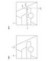
図4Aは第1撮像画像I1の一例を示している。第1撮像画像I1は、単眼カメラ3の画角に対応する角度θに応じた消失点を有しており、かつ、角度θに応じた歪みを有している。FIG. 4A shows an example of the first captured image I1. The first captured image I1 has a vanishing point corresponding to the angle θ corresponding to the angle of view of the
コーナー位置重畳部32は、センサ位置情報及びカメラ位置情報に基づき第1撮像画像I1に第1コーナー位置PC1を重畳することにより、第1撮像画像I1における第1コーナー部に対応する位置を算出するものである。すなわち、コーナー位置重畳部32は、第1撮像画像I1における第1コーナー位置PC1’を算出するものである。The corner
図4Bは、第1撮像画像I1における第1コーナー位置PC1’の一例を示している。なお、図4Bは、第1撮像画像I1における複数個の第1反射点P1に対応する複数個の地点P1’の位置も示している。FIG. 4B shows an example of the first corner position PC1 'in the first captured image I1. FIG. 4B also shows the positions of a plurality of points P1 'corresponding to the plurality of first reflection points P1 in the first captured image I1.
先端位置算出部33は、第1撮像画像I1に対する画像認識処理を実行することにより、第1撮像画像I1における第1駐車車両V1の先端部の位置(以下「第1先端位置」という。)PT1’を算出するものである。この画像認識処理は、例えば、第1撮像画像I1における第1駐車車両V1に対応する領域と他の領域間の境界部を検出する処理を含むものである。The tip
突出量算出部34は、第1撮像画像I1における第1コーナー位置PC1’と第1先端位置PT1’間の距離(すなわちピクセル数)を算出することにより、第1撮像画像I1における第1突出量LP1’を算出するものである。The protrusion
突出量変換部35は、第1撮像画像I1における第1突出量LP1’を実空間における第1突出量LP1に変換するものである。すなわち、突出量変換部35は、ピクセル単位の第1突出量LP1’をメートル単位の第1突出量LP1に変換するものである。当該変換には、突出量変換部35に予め記憶されている変換テーブルTが用いられる。The protrusion
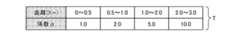
図6は、変換テーブルTの一例を示している。図6に示す如く、変換テーブルTは、車両1と駐車車両V間の距離Dの値の範囲と、変換用の係数αとの対応関係を示すものである。突出量変換部35は、例えば、測距情報が示す車両1と第1駐車車両V1間の距離D1に応じた係数αを第1突出量LP1’に乗算することにより、第1突出量LP1’を第1突出量LP1に変換する。FIG. 6 shows an example of the conversion table T. As shown in FIG. 6, the conversion table T shows the correspondence between the range of the value of the distance D between the vehicle 1 and the parked vehicle V and the conversion coefficient α. For example, the protrusion
ここで、上記のとおり、第1撮像画像I1は角度θに応じた歪みを有している。この歪みは、単眼カメラ3からの距離が大きくなるにつれて次第に縮小倍率の値が大きくなる歪みである。これに対して、係数αは引き伸ばし倍率に対応している。図6に示す如く、係数αは、単眼カメラ3からの距離が大きくなるにつれて次第に引き伸ばし倍率の値が大きくなるように設定されている。このため、第1突出量LP’を第1突出量LP1に変換するとき、係数αの乗算により、第1撮像画像I1の歪みに応じた誤差が第1突出量LP1に発生するのを抑制することができる。すなわち、第1突出量LP1を補正することができる。Here, as described above, the first captured image I1 has a distortion corresponding to the angle θ. This distortion is a distortion in which the value of the reduction magnification gradually increases as the distance from the
また、撮像画像選択部31は、センサ位置情報及びカメラ位置情報を用いて、時間的に連続する複数の撮像画像Iのうちの第2コーナー位置PC2に対応する撮像画像(以下「第2撮像画像」という。)I2を選択するものである。すなわち、第2撮像画像I2は第2コーナー部を含むものである。In addition, the captured
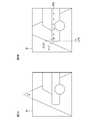
図5Aは第2撮像画像I2の一例を示している。第2撮像画像I2は、単眼カメラ3の画角に対応する角度θに応じた消失点を有しており、かつ、角度θに応じた歪みを有している。FIG. 5A shows an example of the second captured image I2. The second captured image I2 has a vanishing point corresponding to the angle θ corresponding to the angle of view of the
コーナー位置重畳部32は、センサ位置情報及びカメラ位置情報に基づき第2撮像画像I2に第2コーナー位置PC2を重畳することにより、第2撮像画像I2における第2コーナー部に対応する位置を算出するものである。すなわち、コーナー位置重畳部32は、第2撮像画像I2における第2コーナー位置PC2’を算出するものである。The corner
図5Bは、第2撮像画像I2における第2コーナー位置PC2’の一例を示している。なお、図5Bは、第2撮像画像I2における複数個の第2反射点P2に対応する複数個の地点P2’の位置も示している。FIG. 5B shows an example of the second corner position PC2 'in the second captured image I2. FIG. 5B also shows the positions of a plurality of points P2 'corresponding to the plurality of second reflection points P2 in the second captured image I2.
先端位置算出部33は、第2撮像画像I2に対する画像認識処理を実行することにより、第2撮像画像I2における第2駐車車両V2の先端部の位置(以下「第2先端位置」という。)PT2’を算出するものである。この画像認識処理は、例えば、第2撮像画像I2における第2駐車車両V2に対応する領域と他の領域間の境界部を検出する処理を含むものである。The tip
突出量算出部34は、第2撮像画像I2における第2コーナー位置PC2’と第2先端位置PT2’間の距離(すなわちピクセル数)を算出することにより、第2撮像画像I2における第2突出量LP2’を算出するものである。The protrusion
突出量変換部35は、第2撮像画像I2における第2突出量LP2’を実空間における第2突出量LP2に変換するものである。すなわち、突出量変換部35は、ピクセル単位の第2突出量LP2’をメートル単位の第2突出量LP2に変換するものである。第2突出量LP2’,LP2の変換方法は第1突出量LP1’,LP1の変換方法と同様であるため、詳細な説明は省略する。The protrusion
スペース幅算出部23は、第1コーナー位置PC1と第2コーナー位置PC2間の間隔(以下「コーナー間隔」という。)LCを算出するものである。スペース幅算出部23は、コーナー間隔LCから第1突出量LP1及び第2突出量LP2を減算することにより、第1駐車車両V1と第2駐車車両V2間のスペースSの幅(以下「駐車スペース幅」という。)LSを算出するものである。図7は、コーナー間隔LC、第1突出量LP1、第2突出量LP2及び駐車スペース幅LSの一例を示している。The space
駐車可否判定部14は、駐車スペース幅LSを所定の閾値と比較することにより、スペースSに対する車両1の駐車が可能であるか否かを判定するものである。The parking
コーナー位置算出部21、突出量算出部22及びスペース幅算出部23により、駐車支援装置100が構成されている。測距情報生成部11、撮像制御部12、位置情報生成部13、駐車可否判定部14及び駐車支援装置100により、第1ECU4の要部が構成されている。The corner
第2電子制御ユニット(以下「第2ECU」と記載する。)5は、車両1のアクセル、ブレーキ及びステアリングなどを制御する機能を有している。第2ECU5は、駐車可否判定部14によりスペースSに対する車両1の駐車が可能であると判定された場合、いわゆる「自動駐車」を実現するための制御を実行するものである。The second electronic control unit (hereinafter referred to as “second ECU”) 5 has a function of controlling the accelerator, brake, steering, etc. of the vehicle 1. The
次に、図8を参照して、駐車支援装置100のハードウェア構成について説明する。Next, the hardware configuration of the
図8Aに示す如く、駐車支援装置100はコンピュータにより構成されており、当該コンピュータはプロセッサ41及びメモリ42を有している。メモリ42には、当該コンピュータをコーナー位置算出部21、突出量算出部22及びスペース幅算出部23として機能させるためのプログラムが記憶されている。メモリ42に記憶されているプログラムをプロセッサ41が読み出して実行することにより、コーナー位置算出部21、突出量算出部22及びスペース幅算出部23の機能が実現される。As shown in FIG. 8A, the
または、図8Bに示す如く、駐車支援装置100は処理回路43により構成されているものであっても良い。この場合、コーナー位置算出部21、突出量算出部22及びスペース幅算出部23の機能が処理回路43により実現されるものであっても良い。Alternatively, as shown in FIG. 8B, the
または、駐車支援装置100はプロセッサ41、メモリ42及び処理回路43により構成されているものであっても良い(不図示)。この場合、コーナー位置算出部21、突出量算出部22及びスペース幅算出部23の機能のうちの一部の機能がプロセッサ41及びメモリ42により実現されて、残余の機能が処理回路43により実現されるものであっても良い。Or the
プロセッサ41は、例えば、CPU(Central Processing Unit)、GPU(Graphics Processing Unit)、マイクロプロセッサ、マイクロコントローラ又はDSP(Digital Signal Processor)を用いたものである。The
メモリ42は、例えば、半導体メモリ又は磁気ディスクを用いたものである。より具体的には、メモリ42は、RAM(Random Access Memory)、ROM(Read Only Memory)、フラッシュメモリ、EPROM(Erasable Programmable Read Only Memory)、EEPROM(Electrically Erasable Programmable Read-Only Memory)、SSD(Solid State Drive)又はHDD(Hard Disk Drive)などを用いたものである。The
処理回路43は、例えば、ASIC(Application Specific Integrated Circuit)、PLD(Programmable Logic Device)、FPGA(Field-Programmable Gate Array)、SoC(System-on-a-Chip)又はシステムLSI(Large-Scale Integration)を用いたものである。The
なお、第1ECU4のうちの駐車支援装置100を除く部位(すなわち測距情報生成部11、撮像制御部12、位置情報生成部13及び駐車可否判定部14を含む部位)のハードウェア構成は駐車支援装置100のハードウェア構成と同様であるため、図示及び説明を省略する。また、第2ECU5のハードウェア構成は駐車支援装置100のハードウェア構成と同様であるため、図示及び説明を省略する。The hardware configuration of the
次に、図9のフローチャートを参照して、駐車支援装置100の動作について説明する。なお、ステップST1の処理が開始されるよりも先に、測距情報生成部11が測距情報を駐車支援装置100に出力しており、かつ、撮像制御部12が画像データを駐車支援装置100に出力しており、かつ、位置情報生成部13がセンサ位置情報及びカメラ位置情報を駐車支援装置100に出力しているものとする。Next, the operation of the
まず、ステップST1にて、コーナー位置算出部21は、測距情報を用いて第1コーナー位置PC1及び第2コーナー位置PC2を算出する。First, in step ST1, the corner
次いで、ステップST2にて、突出量算出部22は、第1突出量LP1及び第2突出量LP2を算出する。Next, in step ST2, the protrusion
次いで、ステップST3にて、スペース幅算出部23は、コーナー間隔LCを算出する。また、スペース幅算出部23は、コーナー間隔LCから第1突出量LP1及び第2突出量LP2を減算することにより駐車スペース幅LSを算出する。Next, in step ST3, the space
次に、図10のフローチャートを参照して、突出量算出部22の詳細な動作、すなわちステップST2の詳細な処理内容について説明する。Next, the detailed operation of the protrusion
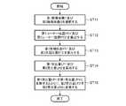
まず、ステップST11にて、撮像画像選択部31は、センサ位置情報及びカメラ位置情報を用いて、撮像画像Iのうちの第1撮像画像I1を選択する。また、撮像画像選択部31は、センサ位置情報及びカメラ位置情報を用いて、撮像画像Iのうちの第2撮像画像I2を選択する。First, in step ST11, the captured
次いで、ステップST12にて、コーナー位置重畳部32は、センサ位置情報及びカメラ位置情報に基づき第1撮像画像I1に第1コーナー位置PC1を重畳することにより、第1撮像画像I1における第1コーナー位置PC1’を算出する。また、コーナー位置重畳部32は、センサ位置情報及びカメラ位置情報に基づき第2撮像画像I2に第2コーナー位置PC2を重畳することにより、第2撮像画像I2における第2コーナー位置PC2’を算出する。Next, in step ST12, the corner
次いで、ステップST13にて、先端位置算出部33は、第1撮像画像I1に対する画像認識処理を実行することにより第1撮像画像I1における第1先端位置PT1’を算出する。また、先端位置算出部33は、第2撮像画像I2に対する画像認識処理を実行することにより第2撮像画像I2における第2先端位置PT2’を算出する。Next, in step ST13, the tip
次いで、ステップST14にて、突出量算出部34は、第1撮像画像I1における第1コーナー位置PC1’と第1先端位置PT1’間の距離を算出することにより、第1撮像画像I1における第1突出量LP1’を算出する。また、突出量算出部34は、第2撮像画像I2における第2コーナー位置PC2’と第2先端位置PT2’間の距離を算出することにより、第2撮像画像I2における第2突出量LP2’を算出する。Next, in step ST14, the protrusion
次いで、ステップST15にて、突出量変換部35は、第1撮像画像I1における第1突出量LP1’を実空間における第1突出量LP1に変換する。また、突出量変換部35は、第2撮像画像I2における第2突出量LP2’を実空間における第2突出量LP2に変換する。これらの変換には、突出量変換部35に予め記憶されている変換テーブルTが用いられる。Next, in step ST15, the protrusion
このように、測距情報に基づくコーナー位置PC1,PC2を撮像画像I1,I2に重畳することにより、測距センサ2及び単眼カメラ3を用いて突出量LP1,LP2を算出することができる。この結果、駐車スペース幅LSを正確に算出することができる。Thus, the projection amounts LP1 and LP2 can be calculated using the
すなわち、TOF方式の原理上、測距情報を用いて先端位置PT1,PT2を検出することは困難である。他方、画像認識処理によりコーナー位置PC1’,PC2’を検出することも困難である。これに対して、実施の形態1の駐車支援装置100は、これらの組み合わせ(いわゆる「カメラフュージョン」)により、ステレオカメラを用いることなく突出量LP1,LP2を算出するものである。ステレオカメラが不要であるため、車両1を安価に実現することができる。That is, on the principle of the TOF method, it is difficult to detect the tip positions PT1 and PT2 using distance measurement information. On the other hand, it is also difficult to detect the corner positions PC1 'and PC2' by image recognition processing. On the other hand, the
なお、駐車車両V1,V2の駐車形態は縦列駐車に限定されるものではなく、並列駐車であっても良い。駐車車両V1,V2の駐車形態が並列駐車である場合も、第1コーナー部の曲率等に応じた第1突出量LP1が発生するとともに、第2コーナー部の曲率等に応じた第2突出量LP2が発生するためである。In addition, the parking form of the parked vehicles V1 and V2 is not limited to parallel parking, and may be parallel parking. Even when the parking mode of the parked vehicles V1 and V2 is parallel parking, the first protrusion amount LP1 corresponding to the curvature of the first corner portion is generated, and the second protrusion amount corresponding to the curvature of the second corner portion, etc. This is because LP2 occurs.
また、測距センサ2及び単眼カメラ3は、車両1の左側部に代えて車両1の右側部に設けられているものであっても良い。In addition, the
また、測距センサ2及び単眼カメラ3は、車両1の左側部及び右側部の各々に設けられているものであっても良い。Further, the
また、位置情報生成部13は、自律航法に代えて又は加えて衛星航法により自車位置を算出するものであっても良い。この場合、第1ECU4は、車両1に設けられているGNSS(Global Navigation Satellite System)受信機からGNSS信号を取得するものであっても良い。Further, the position
以上のように、実施の形態1の駐車支援装置100は、車両1に設けられており、かつ、車両1の側方に向けられている測距センサ2及び単眼カメラ3を用いる駐車支援装置100であって、測距センサ2による測距情報を用いて、第1駐車車両V1の第1コーナー位置PC1及び第2駐車車両V2の第2コーナー位置PC2を算出するコーナー位置算出部21と、単眼カメラ3による撮像画像Iのうちの第1コーナー位置PC1に対応する第1撮像画像I1に第1コーナー位置PC1を重畳することにより第1コーナー位置PC1に対する第1駐車車両V1の第1突出量LP1を算出するとともに、撮像画像Iのうちの第2コーナー位置PC2に対応する第2撮像画像I2に第2コーナー位置PC2を重畳することにより第2コーナー位置PC2に対する第2駐車車両V2の第2突出量LP2を算出する突出量算出部22と、第1コーナー位置PC1と第2コーナー位置PC2間の間隔(コーナー間隔)LCから第1突出量LP1及び第2突出量LP2を減算することにより、第1駐車車両V1と第2駐車車両V2間のスペースSの幅(駐車スペース幅)LSを算出するスペース幅算出部23とを備える。これにより、駐車スペース幅LSを正確に算出することができるため、スペースSに対する車両1の駐車が可能であるか否かを正確に判定することができる。また、ステレオカメラが不要であるため、車両1を安価に実現することができる。As described above, the
また、突出量算出部22において、測距情報に基づき第1突出量LP1及び第2突出量LP2が補正される。変換テーブルTを用いることにより、第1撮像画像I1の歪みによる誤差が第1突出量LP1に発生するのを抑制することができ、かつ、第2撮像画像I2の歪みによる誤差が第2突出量LP2に発生するのを抑制することができる。この結果、駐車スペース幅LSを更に正確に算出することができる。Also, the projection
実施の形態2.
図11は、実施の形態2に係る駐車支援装置が車両内の電子制御ユニットに設けられている状態を示すブロック図である。図12は、実施の形態2に係る駐車支援装置のうちの突出量算出部の要部を示すブロック図である。図11及び図12を参照して、実施の形態2の駐車支援装置100aについて説明する。
FIG. 11 is a block diagram illustrating a state in which the parking assistance apparatus according to the second embodiment is provided in an electronic control unit in a vehicle. FIG. 12 is a block diagram illustrating a main part of the protrusion amount calculation unit in the parking assistance apparatus according to the second embodiment. With reference to FIG.11 and FIG.12, the
なお、図11において、図1に示すブロックと同様のブロックには同一符号を付して説明を省略する。また、図12において、図2に示すブロックと同様のブロックには同一符号を付して説明を省略する。In FIG. 11, the same blocks as those shown in FIG. In FIG. 12, the same blocks as those shown in FIG.
コーナー位置算出部21aは、測距情報を用いて2個の第1コーナー位置PC11,PC12を算出するものである。また、コーナー位置算出部21aは、測距情報を用いて2個の第2コーナー位置PC21,PC22を算出するものである。Corner
例えば、図13に示す如く、駐車車両V1,V2の駐車形態が縦列駐車である場合、第1コーナー位置PC11は第1駐車車両V1の右後端のコーナー部の位置であり、第1コーナー位置PC12は第1駐車車両V1の右前端のコーナー部の位置である。また、第2コーナー位置PC21は第2駐車車両V2の右後端のコーナー部の位置であり、第2コーナー位置PC22は第2駐車車両V2の右前端のコーナー部の位置である。図中、W1は第1駐車車両V1の全幅に対する半分の値を示しており、W2は第2駐車車両V2の全幅に対する半分の値を示している。以下、これらの幅Wを「半車幅」という。For example, as shown in FIG. 13, if the parking mode of the parked vehicle V1, V2 is parallel parking, the first corner position PC11 is the position of the corner portion of the right rear end of the first parked vehicle V1, the first corner position PC12 is the position of the corner portion of the right front end of the first parked vehicle V1. The second corner position PC21 is the position of the corner portion of the right rear end of the second parked vehicle V2, the second corner position PC22 is the position of the corner portion of the right front end of the second parked vehicle V2. In the figure, W1 represents a half value with respect to the full width of the first parked vehicle V1, and W2 represents a half value with respect to the full width of the second parked vehicle V2. Hereinafter, these widths W are referred to as “half-car widths”.
撮像画像選択部31aは、センサ位置情報及びカメラ位置情報を用いて、時間的に連続する複数の撮像画像Iのうちの第1コーナー位置PC12に対応する撮像画像I1、すなわち第1撮像画像I1を選択するものである。また、撮像画像選択部31aは、センサ位置情報及びカメラ位置情報を用いて、時間的に連続する複数の撮像画像Iのうちの第2コーナー位置PC21に対応する撮像画像I2、すなわち第2撮像画像I2を選択するものである。Captured
コーナー位置重畳部32aは、センサ位置情報及びカメラ位置情報に基づき第1撮像画像I1に第1コーナー位置PC12を重畳することにより、第1撮像画像I1における第1コーナー位置PC12’を算出するものである。また、コーナー位置重畳部32aは、センサ位置情報及びカメラ位置情報に基づき第2撮像画像I2に第2コーナー位置PC21を重畳することにより、第2撮像画像I2における第2コーナー位置PC21’を算出するものである。Corner
先端位置算出部33aは、第1撮像画像I1に対する画像認識処理を実行することにより、第1撮像画像I1における第1先端位置PT1’を算出するものである。また、先端位置算出部33aは、第2撮像画像I2に対する画像認識処理を実行することにより、第2撮像画像I2における第2先端位置PT2’を算出するものである。The tip
突出量算出部34aは、第1撮像画像I1における第1コーナー位置PC12’と第1先端位置PT1’間の距離を算出することにより、第1撮像画像I1における第1突出量LP1’を算出するものである。また、突出量算出部34aは、第2撮像画像I2における第2コーナー位置PC21’と第2先端位置PT2’間の距離を算出することにより、第2撮像画像I2における第2突出量LP2’を算出するものである。The protrusion
車長算出部36は、第1コーナー位置PC11,PC12間の長さ(以下「第1車長」という。)LV1を算出するものである。また、車長算出部36は、第2コーナー位置PC21,PC22間の長さ(以下「第2車長」という。)LV2を算出するものである。すなわち、第1車長LV1は第1駐車車両V1の略全長に対応するものであり、第2車長LV2は第2駐車車両V2の略全長に対応するものである。The vehicle
車種判定部37は、第1車長LV1を所定の閾値Lth1,Lth2と比較することにより、第1駐車車両V1の車種を判定するものである。また、車種判定部37は、第2車長LV2を所定の閾値Lth1,Lth2と比較することにより、第2駐車車両V2の車種を判定するものである。The vehicle
例えば、閾値Lth1は3メートルに設定されており、閾値Lth2は5メートルに設定されている。車種判定部37は、第1車長LV1が閾値Lth1未満の値である場合は第1駐車車両V1が軽自動車であると判定して、第1車長LV1が閾値Lth1以上かつ閾値Lth2未満の値である場合は第1駐車車両V1が普通自動車であると判定して、第1車長LV1が閾値Lth2以上の値である場合は第1駐車車両V1がトラック又はバスであると判定する。また、車種判定部37は、第2車長LV2が閾値Lth1未満の値である場合は第2駐車車両V2が軽自動車であると判定して、第2車長LV2が閾値Lth1以上かつ閾値Lth2未満の値である場合は第2駐車車両V2が普通自動車であると判定して、第2車長LV2が閾値Lth2以上の値である場合は第2駐車車両V2がトラック又はバスであると判定する。For example, the threshold value Lth1 is set to 3 meters, and the threshold value Lth2 is set to 5 meters. The vehicle
ここで、突出量変換部35aには、駐車車両Vの車種に対応する複数の変換テーブルTが記憶されている。例えば、図14に示す如く、軽自動車に対応する変換テーブルT1と、普通自動車に対応する変換テーブルT2と、トラック及びバスに対応する変換テーブルT3とが記憶されている。Here, a plurality of conversion tables T corresponding to the vehicle type of the parked vehicle V are stored in the protrusion
通常、第1駐車車両V1の半車幅W1は第1駐車車両V1の車種に応じて異なるものであり、第2駐車車両V2の半車幅W2は第2駐車車両V2の車種に応じて異なるものである。このため、係数αの乗算による補正の精度を向上する観点から、半車幅Wに応じて(すなわち駐車車両Vの車種に応じて)異なる係数αを用いるのが好適である。そこで、複数の変換テーブルTの各々における係数αは、対応する車種の標準的な半車幅Wを考慮して設定された値となっている。Usually, the half vehicle width W1 of the first parked vehicle V1 varies depending on the vehicle type of the first parked vehicle V1, and the half vehicle width W2 of the second parked vehicle V2 varies depending on the vehicle type of the second parked vehicle V2. Is. For this reason, it is preferable to use a different coefficient α according to the half vehicle width W (that is, according to the type of the parked vehicle V) from the viewpoint of improving the accuracy of correction by multiplication of the coefficient α. Therefore, the coefficient α in each of the plurality of conversion tables T is a value set in consideration of the standard half vehicle width W of the corresponding vehicle type.
テーブル選択部38は、第1駐車車両V1の車種に応じて第1突出量LP1’用の変換テーブルTを選択するものである。具体的には、例えば、テーブル選択部38は、第1駐車車両V1の車種が軽自動車である場合は変換テーブルT1を選択して、第1駐車車両V1の車種が普通自動車である場合は変換テーブルT2を選択して、第1駐車車両V1の車種がトラック又はバスである場合は変換テーブルT3を選択する。突出量変換部35aは、当該選択された変換テーブルTを用いて第1突出量LP1’を第1突出量LP1に変換するようになっている。The
また、テーブル選択部38は、第2駐車車両V2の車種に応じて第2突出量LP2’用の変換テーブルTを選択するものである。具体的には、例えば、テーブル選択部38は、第2駐車車両V2の車種が軽自動車である場合は変換テーブルT1を選択して、第2駐車車両V2の車種が普通自動車である場合は変換テーブルT2を選択して、第2駐車車両V2の車種がトラック又はバスである場合は変換テーブルT3を選択する。突出量変換部35aは、当該選択された変換テーブルTを用いて第2突出量LP2’を第2突出量LP2に変換するようになっている。The
スペース幅算出部23aは、第1コーナー位置PC12と第2コーナー位置PC21間の間隔LC、すなわちコーナー間隔LCを算出するものである。スペース幅算出部23aは、コーナー間隔LCから第1突出量LP1及び第2突出量LP2を減算することにより、駐車スペース幅LSを算出するものである。Space
撮像画像選択部31a、コーナー位置重畳部32a、先端位置算出部33a、突出量算出部34a、突出量変換部35a、車長算出部36、車種判定部37及びテーブル選択部38により、突出量算出部22aが構成されている。コーナー位置算出部21a、突出量算出部22a及びスペース幅算出部23aにより、駐車支援装置100aが構成されている。Projection amount calculation is performed by the captured
駐車支援装置100aのハードウェア構成は、実施の形態1にて図8を参照して説明したものと同様であるため、図示及び説明を省略する。すなわち、コーナー位置算出部21a、突出量算出部22a及びスペース幅算出部23aの各々の機能は、プロセッサ41及びメモリ42により実現されるものであっても良く、又は処理回路43により実現されるものであっても良い。Since the hardware configuration of the
次に、図15のフローチャートを参照して、駐車支援装置100aの動作について説明する。なお、ステップST1aの処理が開始されるよりも先に、測距情報生成部11が測距情報を駐車支援装置100aに出力しており、かつ、撮像制御部12が画像データを駐車支援装置100aに出力しており、かつ、位置情報生成部13がセンサ位置情報及びカメラ位置情報を駐車支援装置100aに出力しているものとする。Next, the operation of the
まず、ステップST1aにて、コーナー位置算出部21aは、測距情報を用いて第1コーナー位置PC11,PC12及び第2コーナー位置PC21,PC22を算出する。First, in step ST1a, the corner
次いで、ステップST2aにて、突出量算出部22aは、第1突出量LP1及び第2突出量LP2を算出する。Next, in step ST2a, the protrusion
次いで、ステップST3aにて、スペース幅算出部23aは、コーナー間隔LCを算出する。また、スペース幅算出部23aは、コーナー間隔LCから第1突出量LP1及び第2突出量LP2を減算することにより駐車スペース幅LSを算出する。Next, in step ST3a, the space
次に、図16のフローチャートを参照して、突出量算出部22aの詳細な動作、すなわちステップST2aの詳細な処理内容について説明する。Next, the detailed operation of the protrusion
まず、ステップST11aにて、撮像画像選択部31aは、センサ位置情報及びカメラ位置情報を用いて、撮像画像Iのうちの第1撮像画像I1を選択する。また、撮像画像選択部31aは、センサ位置情報及びカメラ位置情報を用いて、撮像画像Iのうちの第2撮像画像I2を選択する。First, in step ST11a, the captured
次いで、ステップST12aにて、コーナー位置重畳部32aは、センサ位置情報及びカメラ位置情報に基づき第1撮像画像I1に第1コーナー位置PC12を重畳することにより、第1撮像画像I1における第1コーナー位置PC12’を算出する。また、コーナー位置重畳部32aは、センサ位置情報及びカメラ位置情報に基づき第2撮像画像I2に第2コーナー位置PC21を重畳することにより、第2撮像画像I2における第2コーナー位置PC21’を算出する。Then, in step ST12a, the corner
次いで、ステップST13aにて、先端位置算出部33aは、第1撮像画像I1に対する画像認識処理を実行することにより第1撮像画像I1における第1先端位置PT1’を算出する。また、先端位置算出部33aは、第2撮像画像I2に対する画像認識処理を実行することにより第2撮像画像I2における第2先端位置PT2’を算出する。Next, in step ST13a, the tip
次いで、ステップST14aにて、突出量算出部34aは、第1撮像画像I1における第1コーナー位置PC12’と第1先端位置PT1’間の距離を算出することにより、第1撮像画像I1における第1突出量LP1’を算出する。また、突出量算出部34は、第2撮像画像I2における第2コーナー位置PC21’と第2先端位置PT2’間の距離を算出することにより、第2撮像画像I2における第2突出量LP2’を算出する。Next, in step ST14a, the protrusion
次いで、ステップST16にて、車長算出部36は、第1車長LV1及び第2車長LV2を算出する。Next, in step ST16, the vehicle
次いで、ステップST17にて、車種判定部37は、第1車長LV1を閾値Lth1,Lth2と比較することにより第1駐車車両V1の車種を判定する。また、車種判定部37は、第2車長LV2を閾値Lth1,Lth2と比較することにより第2駐車車両V2の車種を判定する。Next, in step ST17, the vehicle
次いで、ステップST18にて、テーブル選択部38は、第1駐車車両V1の車種に応じて第1突出量LP1’用の変換テーブルTを選択する。また、テーブル選択部38は、第2駐車車両V2の車種に応じて第2突出量LP2’用の変換テーブルTを選択する。Next, in step ST18, the
次いで、ステップST15aにて、突出量変換部35aは、第1撮像画像I1における第1突出量LP1’を実空間における第1突出量LP1に変換する。また、突出量変換部35aは、第2撮像画像I2における第2突出量LP2’を実空間における第2突出量LP2に変換する。これらの変換には、ステップST18にて選択された変換テーブルTが用いられる。Next, in step ST15a, the protrusion
このように、駐車車両Vの車種に応じて異なる変換テーブルTを用いることにより、撮像画像I1,I2の歪みに応じた補正の精度を向上することができる。Thus, by using different conversion tables T according to the type of the parked vehicle V, the accuracy of correction according to the distortion of the captured images I1 and I2 can be improved.
なお、駐車支援装置100aは、実施の形態1にて説明したものと同様の種々の変形例を採用することができる。In addition, the
実施の形態3.
図17は、実施の形態3に係る駐車支援装置が車両内の電子制御ユニットに設けられている状態を示すブロック図である。図17を参照して、実施の形態3の駐車支援装置100bについて説明する。なお、図17において、図1に示すブロックと同様のブロックには同一符号を付して説明を省略する。
FIG. 17 is a block diagram illustrating a state in which the parking assist device according to
撮像制御部12は、駐車可否判定部14によりスペースSに対する車両1の駐車が可能であると判定された場合、所定の時間間隔にて単眼カメラ3に画像Iを撮像させるようになっている。すなわち、これらの画像Iは、第2ECU5が自動駐車を実現するための制御を実行しているときに撮像されるものである。撮像制御部12は、これらの画像Iを示す画像データを単眼カメラ3から取得して、当該取得された画像データを駐車支援装置100bに出力するようになっている。The
ここで、単眼カメラ3は車両1の側方に向けられている。このため、単眼カメラ3による撮像画像Iは、いわゆる「サイドビュー画像」である。表示制御部24は、駐車可否判定部14によりスペースSに対する車両1の駐車が可能であると判定された場合における撮像画像Iをサイドビュー画像から鳥瞰画像(いわゆる「トップビュー画像」)I’に変換するものである。サイドビュー画像からトップビュー画像への変換には公知の種々の方法を用いることができるものであり、詳細な説明は省略する。Here, the
一般に、サイドビュー画像から変換されたトップビュー画像は当該変換時に生じた歪みを有している。このため、鳥瞰画像I’における第1突出量LP1”は実際の第1突出量LP1に対する誤差を有しており、鳥瞰画像I’における第2突出量LP2”は実際の第2突出量LP2に対する誤差を有している。そこで、表示制御部24は、鳥瞰画像I’における第1突出量LP1”が突出量算出部22により算出された第1突出量LP1に対応する値となるように鳥瞰画像I’を補正するものである。また、表示制御部24は、鳥瞰画像I’における第2突出量LP2”が突出量算出部22により算出された第2突出量LP2に対応する値となるように鳥瞰画像I’を補正するものである。Generally, a top view image converted from a side view image has a distortion generated during the conversion. For this reason, the first protrusion amount LP1 ″ in the bird's-eye image I ′ has an error with respect to the actual first protrusion amount LP1, and the second protrusion amount LP2 ″ in the bird's-eye image I ′ is relative to the actual second protrusion amount LP2. Has an error. Therefore, the
表示制御部24は、補正後の鳥瞰画像I’を表示装置6に表示させるものである。表示装置6は、例えば、液晶ディスプレイ又は有機EL(Electro-Luminescence)ディスプレイにより構成されている。表示装置6は、例えば、車両1のダッシュボードに設けられている。The
コーナー位置算出部21、突出量算出部22、スペース幅算出部23及び表示制御部24により、駐車支援装置100bが構成されている。The corner
駐車支援装置100bのハードウェア構成は、実施の形態1にて図8を参照して説明したものと同様であるため、図示及び説明を省略する。すなわち、コーナー位置算出部21、突出量算出部22、スペース幅算出部23及び表示制御部24の各々の機能は、プロセッサ41及びメモリ42により実現されるものであっても良く、又は処理回路43により実現されるものであっても良い。Since the hardware configuration of the
コーナー位置算出部21、突出量算出部22及びスペース幅算出部23の動作は、実施の形態1にて図9のフローチャートを参照して説明したものと同様であるため、図示及び説明を省略する。また、突出量算出部22の詳細な動作は、実施の形態1にて図10のフローチャートを参照して説明したものと同様であるため、図示及び説明を省略する。Since the operations of the corner
次に、図18のフローチャートを参照して、表示制御部24の詳細な動作について説明する。Next, the detailed operation of the
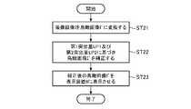
駐車可否判定部14によりスペースSに対する車両1の駐車が可能であると判定された場合、表示制御部24はステップST21の処理を開始する。すなわち、ステップST21~ST23の処理は、第2ECU5が自動駐車を実現するための制御を実行しているときに実行されるものである。When it is determined by the parking
まず、ステップST21にて、表示制御部24は、単眼カメラ3による撮像画像Iを鳥瞰画像I’に変換する。First, in step ST21, the
次いで、ステップST22にて、表示制御部24は、鳥瞰画像I’における第1突出量LP1”が突出量算出部22により算出された第1突出量LP1に対応する値となるように鳥瞰画像I’を補正する。また、表示制御部24は、鳥瞰画像I’における第2突出量LP2”が突出量算出部22により算出された第2突出量LP2に対応する値となるように鳥瞰画像I’を補正する。Next, in step ST22, the
次いで、ステップST23にて、表示制御部24は、補正後の鳥瞰画像I’を表示装置6に表示させる。Next, in step ST23, the
通常、第2ECU5による自動駐車において、車両1は駐車車両Vのコーナー部に対するすれすれの位置を通過する。表示装置6における鳥瞰画像I’の表示は、車両1が駐車車両Vのコーナー部にぶつからないことを車両1の搭乗者に視覚的に知らせることにより、車両1の搭乗者を安心させるためのものである。Usually, in the automatic parking by the
しかしながら、上記のとおりトップビュー画像はサイドビュー画像からの変換時に生じた歪みを有しているため、補正前の鳥瞰画像I’における突出量LP1”,LP2”が実際の突出量LP1,LP2に比して大きい場合がある。この場合、実際には車両1が駐車車両Vのコーナー部にぶつからないにもかかわらず車両1が駐車車両Vのコーナー部にぶつかるような画像表示がなされて、車両1の搭乗者を安心させる効果を得ることができない可能性がある。However, as described above, the top view image has distortion generated when converted from the side view image. Therefore, the protrusion amounts LP1 ″ and LP2 ″ in the bird's-eye image I ′ before correction become the actual protrusion amounts LP1 and LP2. It may be larger than that. In this case, an image is displayed so that the vehicle 1 hits the corner of the parked vehicle V even though the vehicle 1 does not actually hit the corner of the parked vehicle V, thereby relieving the passenger of the vehicle 1. You may not be able to get
これに対して、上記のように鳥瞰画像I’を補正することにより、実際には車両1が駐車車両Vのコーナー部にぶつからないにもかかわらず車両1が駐車車両Vのコーナー部にぶつかるような画像表示がなされるのを回避することができる。この結果、車両1の搭乗者を安心させる効果をより確実に得ることができる。On the other hand, by correcting the bird's-eye view image I ′ as described above, the vehicle 1 hits the corner of the parked vehicle V even though the vehicle 1 does not actually hit the corner of the parked vehicle V. It is possible to avoid an image display. As a result, the effect of reassuring the passenger of the vehicle 1 can be obtained more reliably.
なお、鳥瞰画像I’に変換される画像Iは、車両1に設けられている複数個の単眼カメラ3により撮像されたものであっても良い。例えば、車両1の左方に向けらている単眼カメラ3に加えて、車両1の右方に向けられている単眼カメラ3、車両1の前方に向けられている単眼カメラ3及び車両1の後方に向けられている単眼カメラ3が車両1に設けられており、これらの単眼カメラ3による撮像画像Iが鳥瞰画像I’に変換されるものであっても良い。Note that the image I converted into the bird's-eye view image I ′ may be captured by a plurality of
また、駐車支援装置100bは、実施の形態2の駐車支援装置100aに表示制御部24を付加してなるものであっても良い。この場合のブロック図を図19に示す。Further, the
また、駐車支援装置100bは、実施の形態1にて説明したものと同様の種々の変形例を採用することができる。Moreover, the
以上のように、実施の形態3の駐車支援装置100bは、撮像画像Iを鳥瞰画像I’に変換して、第1突出量LP1及び第2突出量LP2に基づき鳥瞰画像I’を補正して、補正後の鳥瞰画像I’を表示装置6に表示させる表示制御部24を備える。補正後の鳥瞰画像I’を表示装置6に表示させることにより、車両1が駐車車両Vのコーナー部にぶつからないことを車両1の搭乗者に視覚的に知らせることができる。As described above, the
なお、本願発明はその発明の範囲内において、各実施の形態の自由な組み合わせ、あるいは各実施の形態の任意の構成要素の変形、もしくは各実施の形態において任意の構成要素の省略が可能である。In the present invention, within the scope of the invention, any combination of the embodiments, or any modification of any component in each embodiment, or omission of any component in each embodiment is possible. .
本発明の駐車支援装置は、例えば、自動駐車に応用することができる。The parking assist device of the present invention can be applied to automatic parking, for example.
1 車両、2 測距センサ、3 単眼カメラ、4 第1電子制御ユニット(第1ECU)、5 第2電子制御ユニット(第2ECU)、6 表示装置、11 測距情報生成部、12 撮像制御部、13 位置情報生成部、14 駐車可否判定部、21,21a コーナー位置算出部、22,22a 突出量算出部、23,23a スペース幅算出部、24 表示制御部、31,31a 撮像画像選択部、32,32a コーナー位置重畳部、33,33a 先端位置算出部、34,34a 突出量算出部、35,35a 突出量変換部、36 車長算出部、37 車種判定部、38 テーブル選択部、41 プロセッサ、42 メモリ、43 処理回路、100,100a,100b 駐車支援装置。1 vehicle, 2 ranging sensor, 3 monocular camera, 4 first electronic control unit (first ECU), 5 second electronic control unit (second ECU), 6 display device, 11 ranging information generating unit, 12 imaging control unit, 13 Position information generation unit, 14 Parking availability determination unit, 21, 21a Corner position calculation unit, 22, 22a Projection amount calculation unit, 23, 23a Space width calculation unit, 24 Display control unit, 31, 31a Captured image selection unit, 32 , 32a corner position superposition unit, 33, 33a tip position calculation unit, 34, 34a projection amount calculation unit, 35, 35a projection amount conversion unit, 36 vehicle length calculation unit, 37 vehicle type determination unit, 38 table selection unit, 41 processor, 42 memory, 43 processing circuit, 100, 100a, 100b parking assistance device.
Claims (3)
Translated fromJapanese前記測距センサによる測距情報を用いて、第1駐車車両の第1コーナー位置及び第2駐車車両の第2コーナー位置を算出するコーナー位置算出部と、
前記単眼カメラによる撮像画像のうちの前記第1コーナー位置に対応する第1撮像画像に前記第1コーナー位置を重畳することにより前記第1コーナー位置に対する前記第1駐車車両の第1突出量を算出するとともに、前記撮像画像のうちの前記第2コーナー位置に対応する第2撮像画像に前記第2コーナー位置を重畳することにより前記第2コーナー位置に対する前記第2駐車車両の第2突出量を算出する突出量算出部と、
前記第1コーナー位置と前記第2コーナー位置間の間隔から前記第1突出量及び前記第2突出量を減算することにより、前記第1駐車車両と前記第2駐車車両間のスペースの幅を算出するスペース幅算出部と、
を備えることを特徴とする駐車支援装置。A parking assist device using a distance measuring sensor and a monocular camera that are provided in a vehicle and are directed to the side of the vehicle,
A corner position calculation unit that calculates the first corner position of the first parked vehicle and the second corner position of the second parked vehicle using the distance measurement information by the distance sensor;
The first protrusion amount of the first parked vehicle with respect to the first corner position is calculated by superimposing the first corner position on the first captured image corresponding to the first corner position in the captured image by the monocular camera. And calculating the second protrusion amount of the second parked vehicle with respect to the second corner position by superimposing the second corner position on the second captured image corresponding to the second corner position of the captured image. A protrusion amount calculation unit to perform,
A space width between the first parked vehicle and the second parked vehicle is calculated by subtracting the first projecting amount and the second projecting amount from an interval between the first corner position and the second corner position. A space width calculation unit,
A parking assistance device comprising:
Priority Applications (1)
| Application Number | Priority Date | Filing Date | Title |
|---|---|---|---|
| PCT/JP2018/017644WO2019215789A1 (en) | 2018-05-07 | 2018-05-07 | Parking assistance device |
Applications Claiming Priority (1)
| Application Number | Priority Date | Filing Date | Title |
|---|---|---|---|
| PCT/JP2018/017644WO2019215789A1 (en) | 2018-05-07 | 2018-05-07 | Parking assistance device |
Publications (1)
| Publication Number | Publication Date |
|---|---|
| WO2019215789A1true WO2019215789A1 (en) | 2019-11-14 |
Family
ID=68467332
Family Applications (1)
| Application Number | Title | Priority Date | Filing Date |
|---|---|---|---|
| PCT/JP2018/017644CeasedWO2019215789A1 (en) | 2018-05-07 | 2018-05-07 | Parking assistance device |
Country Status (1)
| Country | Link |
|---|---|
| WO (1) | WO2019215789A1 (en) |
Citations (7)
| Publication number | Priority date | Publication date | Assignee | Title |
|---|---|---|---|---|
| JP2001315603A (en)* | 2000-05-09 | 2001-11-13 | Matsushita Electric Ind Co Ltd | Driving support device |
| JP2002123818A (en)* | 2000-10-12 | 2002-04-26 | Nissan Motor Co Ltd | Peripheral obstacle detection device for vehicles |
| JP2002359838A (en)* | 2001-03-28 | 2002-12-13 | Matsushita Electric Ind Co Ltd | Driving support device |
| JP2006129021A (en)* | 2004-10-28 | 2006-05-18 | Denso Corp | Parking assistance system |
| JP2007004697A (en)* | 2005-06-27 | 2007-01-11 | Aisin Seiki Co Ltd | Obstacle detection device |
| JP2010267115A (en)* | 2009-05-15 | 2010-11-25 | Bosch Corp | Vehicle parking support device |
| JP2017154711A (en)* | 2016-03-04 | 2017-09-07 | アイシン精機株式会社 | Parking assistance device |
- 2018
- 2018-05-07WOPCT/JP2018/017644patent/WO2019215789A1/ennot_activeCeased
Patent Citations (7)
| Publication number | Priority date | Publication date | Assignee | Title |
|---|---|---|---|---|
| JP2001315603A (en)* | 2000-05-09 | 2001-11-13 | Matsushita Electric Ind Co Ltd | Driving support device |
| JP2002123818A (en)* | 2000-10-12 | 2002-04-26 | Nissan Motor Co Ltd | Peripheral obstacle detection device for vehicles |
| JP2002359838A (en)* | 2001-03-28 | 2002-12-13 | Matsushita Electric Ind Co Ltd | Driving support device |
| JP2006129021A (en)* | 2004-10-28 | 2006-05-18 | Denso Corp | Parking assistance system |
| JP2007004697A (en)* | 2005-06-27 | 2007-01-11 | Aisin Seiki Co Ltd | Obstacle detection device |
| JP2010267115A (en)* | 2009-05-15 | 2010-11-25 | Bosch Corp | Vehicle parking support device |
| JP2017154711A (en)* | 2016-03-04 | 2017-09-07 | アイシン精機株式会社 | Parking assistance device |
Similar Documents
| Publication | Publication Date | Title |
|---|---|---|
| US10988139B2 (en) | Vehicle position control method and device vehicle position control device for correcting position in drive-assisted vehicle | |
| US8130120B2 (en) | Parking assistance device | |
| US9151626B1 (en) | Vehicle position estimation system | |
| JP6625228B2 (en) | Parking assistance device | |
| US10508912B2 (en) | Road surface shape measuring device, measuring method, and non-transitory computer-readable medium | |
| US7697029B2 (en) | Image display apparatus and method | |
| US20100235053A1 (en) | Parking assist device | |
| US11024174B2 (en) | Parking space detection apparatus | |
| JP6616257B2 (en) | Position estimation device | |
| US10884125B2 (en) | Parking assistance device | |
| US20190346273A1 (en) | Host vehicle position estimation device | |
| JP6567936B2 (en) | Steering support control device | |
| JP2020021179A (en) | Driving support device | |
| JP2007188354A (en) | Vehicle front three-dimensional object recognition device | |
| JP2020047210A (en) | Object detection device | |
| JP6604052B2 (en) | Runway boundary estimation device and runway boundary estimation method | |
| KR101734726B1 (en) | Method of tracking parking space and apparatus performing the same | |
| JP7204612B2 (en) | POSITION AND POSTURE ESTIMATION DEVICE, POSITION AND POSTURE ESTIMATION METHOD, AND PROGRAM | |
| JP2019197418A (en) | Obstacle detection apparatus | |
| JP4742775B2 (en) | Other vehicle information providing device | |
| WO2019215789A1 (en) | Parking assistance device | |
| JP7444123B2 (en) | Data correction device, data correction method, data correction program, and vehicle | |
| US20230410383A1 (en) | Display control device, display device, display system, vehicle, display control method, and non-transitory storage medium | |
| JP7211397B2 (en) | Other vehicle display system | |
| US11922836B2 (en) | Rendering system, display system, display control system, and rendering method |
Legal Events
| Date | Code | Title | Description |
|---|---|---|---|
| 121 | Ep: the epo has been informed by wipo that ep was designated in this application | Ref document number:18917803 Country of ref document:EP Kind code of ref document:A1 | |
| NENP | Non-entry into the national phase | Ref country code:DE | |
| 122 | Ep: pct application non-entry in european phase | Ref document number:18917803 Country of ref document:EP Kind code of ref document:A1 | |
| NENP | Non-entry into the national phase | Ref country code:JP |