WO2019208902A1 - Wireless power transmission device, and electronic device for wirelessly receiving power and operating method therefor - Google Patents
Wireless power transmission device, and electronic device for wirelessly receiving power and operating method thereforDownload PDFInfo
- Publication number
- WO2019208902A1 WO2019208902A1PCT/KR2018/016556KR2018016556WWO2019208902A1WO 2019208902 A1WO2019208902 A1WO 2019208902A1KR 2018016556 WKR2018016556 WKR 2018016556WWO 2019208902 A1WO2019208902 A1WO 2019208902A1
- Authority
- WO
- WIPO (PCT)
- Prior art keywords
- communication
- electronic device
- information
- frequency
- wave
- Prior art date
- Legal status (The legal status is an assumption and is not a legal conclusion. Google has not performed a legal analysis and makes no representation as to the accuracy of the status listed.)
- Ceased
Links
Images


Classifications
- H—ELECTRICITY
- H02—GENERATION; CONVERSION OR DISTRIBUTION OF ELECTRIC POWER
- H02J—CIRCUIT ARRANGEMENTS OR SYSTEMS FOR SUPPLYING OR DISTRIBUTING ELECTRIC POWER; SYSTEMS FOR STORING ELECTRIC ENERGY
- H02J50/00—Circuit arrangements or systems for wireless supply or distribution of electric power
- H02J50/20—Circuit arrangements or systems for wireless supply or distribution of electric power using microwaves or radio frequency waves
- H—ELECTRICITY
- H02—GENERATION; CONVERSION OR DISTRIBUTION OF ELECTRIC POWER
- H02J—CIRCUIT ARRANGEMENTS OR SYSTEMS FOR SUPPLYING OR DISTRIBUTING ELECTRIC POWER; SYSTEMS FOR STORING ELECTRIC ENERGY
- H02J50/00—Circuit arrangements or systems for wireless supply or distribution of electric power
- H02J50/80—Circuit arrangements or systems for wireless supply or distribution of electric power involving the exchange of data, concerning supply or distribution of electric power, between transmitting devices and receiving devices
Definitions
- Various embodiments of the present disclosurerelate to a wireless power transmitter and an electronic device for wirelessly receiving power, and a method of operating the same, and more particularly, to a wireless power transmitter and an electronic device for wirelessly receiving power. It relates to the operation method.
- Wireless power transmissionincludes magnetic induction, magnetic resonance, and electromagnetic waves.
- Magnetic induction or magnetic resonanceis advantageous for charging an electronic device located at a relatively short distance from a wireless power transmission device.
- the electromagnetic wave methodis more advantageous for long distance power transmission of several m to the magnetic induction or the magnetic resonance method.
- Electromagnetic wave methodis mainly used for long distance power transmission, and can locate power receiver in remote place and transmit power most efficiently.
- An electronic device that wirelessly receives power based on an electromagnetic wave methodmay receive power wirelessly by converting a radio frequency (RF) wave formed from the wireless power transmitter into electrical energy. Meanwhile, the electronic device may communicate with another electronic device. In this case, when the frequency of the RF wave and the frequency for communication with other electronic devices are close to each other, the RF wave and the communication signal may interfere with each other. Due to the interference of the RF wave and the communication signal, the data throughput of the communication signal may be lowered, or the efficiency of wireless charging may be lowered.
- RFradio frequency
- a wireless power transmittercapable of receiving information about a corresponding communication environment from an electronic device communicating with another electronic device and controlling a transmission condition of an RF wave based on the received information about the communication environment And a method of operating the same.
- various embodimentsmay provide an electronic device for transmitting information about a communication environment with another electronic device to a wireless power transmitter and an operation method thereof.
- an apparatus for transmitting powerwirelessly includes a first type communication circuit, a power source for generating a source signal, a power transmission circuit for forming an RF wave based on the source signal, and a control circuit.
- the circuitreceives a communication signal including information on a communication environment according to the second type of communication from the electronic device supporting the first type of communication and the second type of communication through the first type of communication circuit.
- the controllermay be configured to control at least one of a frequency of the source signal generated by the power source or a transmission strength of the RF wave based on the information on the communication environment according to the second type of communication.
- a method of operating a wireless power transmission apparatusincluding a first scheme communication circuit, a power source for generating a source signal, a power transmission circuit for forming an RF wave based on the source signal, and a control circuit, Receiving a communication signal including information on a communication environment according to the second type of communication from the electronic device supporting the first type of communication and the second type of communication through the first type of communication circuit, And controlling at least one of a frequency of the source signal generated by the power source or a transmission strength of the RF wave based on the information on the communication environment according to the second type of communication.
- an electronic devicemay include: a power receiving circuit configured to convert an RF wave formed from a wireless power transmitter into electrical energy, a first scheme communication circuit configured to perform first scheme communication with the wireless power transmitter; A second mode communication circuit configured to perform second mode communication with an access point, and a control circuit, wherein the control circuit is configured to communicate in accordance with a second mode communication received via the second mode communication circuit; Confirming the reception strength of the signal, confirming a data throughput rate according to the second method communication, or a frequency according to the second method communication, receiving strength of the communication signal according to the second method communication, the The first including at least one of a data transmission rate according to a second method communication or a frequency according to the second method communication; The communication signal according to the scheme communication may be set to be transmitted to the wireless power transmitter through the first scheme communication circuit.
- a wireless power transmission apparatusincludes a first type communication circuit, a second type communication circuit, a power source for generating a source signal, a power transmission circuit for forming an RF wave based on the source signal, and a control circuit.
- the control circuitis configured to transmit and / or receive at least one first communication signal with an electronic device via the first method communication circuit, and at least one second through the second method communication circuit. Transmitting and / or receiving a communication signal with an electronic device, and based on at least one of the at least one second communication signal or information included in the at least one first communication signal, communication of the second type communication circuit. Confirming the information on the environment and based on the information on the communication environment of the second type communication circuit, the frequency of the source signal generated by the power source Of, or the transmission intensity of the RF waves may be set to control at least one.
- a wireless power transmission apparatusincludes a first type communication circuit, a second type communication circuit, a power source for generating a source signal, a power transmission circuit for forming an RF wave based on the source signal, and a control circuit.
- the control circuitis configured to transmit and / or receive at least one first communication signal with an electronic device via the first method communication circuit, and at least one second through the second method communication circuit. Transmitting and / or receiving a communication signal with an electronic device, and based on at least one of the at least one second communication signal or information included in the at least one first communication signal, communication of the second type communication circuit. Confirm the information on the environment, and control the communication conditions of the second communication method communication circuit based on the information on the communication environment of the second method communication circuit. It may be set the lock.
- an apparatus for transmitting powerwirelessly includes a first type communication circuit, a power source for generating a source signal, a power transmission circuit for forming an RF wave based on the source signal, and a control circuit.
- the circuitrycontrols the power source and the power transmission circuit to transmit a beacon signal for turning on a first scheme communication circuit of the electronic device for wirelessly receiving power, and based on the beacon signal.
- the power sourceto receive a communication signal transmitted from the first method communication circuit of the terminal through the first method communication circuit and to transmit an RF wave for charging the electronic device in response to receiving the communication signal. It can be set to control the power transmission circuit.
- wireless power transmissionmay receive information about a corresponding communication environment from an electronic device communicating with another electronic device, and control a transmission condition of an RF wave based on the received information about the communication environment.
- An apparatus and a method of operating the samemay be provided.
- an electronic device for transmitting information about a communication environment with another electronic device to a wireless power transmission device and a method of operating the samemay be provided.
- FIG. 1is a conceptual diagram illustrating a wireless power transmission system according to various embodiments of the present disclosure.
- FIG. 2Ais a block diagram of a wireless power transmitter and an electronic device according to various embodiments of the present disclosure.
- 2Bis a detailed block diagram of a power transmission circuit and a power reception circuit according to an electromagnetic wave method according to various embodiments of the present disclosure.
- 3Ais a flowchart illustrating a method of operating a wireless power transmitter and an electronic device according to various embodiments of the present disclosure.
- 3Bis a flowchart illustrating a method of operating a wireless power transmitter and an electronic device according to various embodiments of the present disclosure.
- FIG. 4is a flowchart illustrating a method of operating a wireless power transmitter according to various embodiments of the present disclosure.
- FIG. 5illustrates an example of frequency hopping in accordance with various embodiments.
- FIG. 6is a flowchart illustrating a method of operating a wireless power transmitter according to various embodiments of the present disclosure.
- FIG. 7A and 7Billustrate data formats of communication signals according to various embodiments.
- FIG. 8is a flowchart illustrating a method of operating a wireless power transmitter and an electronic device according to various embodiments of the present disclosure.
- 9Ais a flowchart illustrating a method of operating a wireless power transmitter and an electronic device according to various embodiments of the present disclosure.
- 9Bis a flowchart illustrating a method of operating a wireless power transmitter and an electronic device according to various embodiments of the present disclosure.
- FIG. 10is a flowchart illustrating a method of operating a wireless power transmitter, an electronic device, and a server, according to various embodiments.
- FIG. 11is a flowchart illustrating a method of operating a wireless power transmitter and an electronic device according to various embodiments of the present disclosure.
- FIG. 12is a flowchart illustrating a method of operating a wireless power transmitter, an electronic device, and an AP according to various embodiments of the present disclosure.
- FIG. 13is a flowchart illustrating a method of operating a wireless power transmitter and an electronic device according to various embodiments of the present disclosure.
- FIG 14illustrates an electronic device according to various embodiments of the present disclosure.
- 15is a flowchart illustrating a method of operating a wireless power transmitter according to various embodiments of the present disclosure.
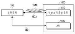
- 16is a block diagram of an external electronic device and an electronic device according to various embodiments of the present disclosure.
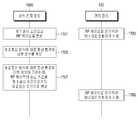
- 17Ais a flowchart illustrating an external electronic device and an operating method of the electronic device according to various embodiments of the present disclosure.
- 17Bis a flowchart illustrating an external electronic device and an operating method of the electronic device according to various embodiments of the present disclosure.
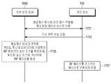
- 17Cis a flowchart illustrating an external electronic device and an operating method of the electronic device according to various embodiments of the present disclosure.
- 17Dis a flowchart illustrating an external electronic device and an operating method of the electronic device according to various embodiments of the present disclosure.
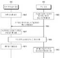
- FIG. 18is a flowchart illustrating a method of operating a wireless power transmitter and an electronic device according to various embodiments of the present disclosure.
- 19is a flowchart illustrating a method of operating a wireless power transmitter, an electronic device, and an AP according to various embodiments of the present disclosure.
- 20is a flowchart illustrating an external electronic device and an operating method of the electronic device according to various embodiments of the present disclosure.
- the expression “device configured to”may mean that the device “can” together with other devices or components.
- processor configured (or configured to) perform A, B, and Cmay be implemented by executing a dedicated processor (eg, an embedded processor) to perform its operation, or one or more software programs stored in a memory device. It may mean a general purpose processor (eg, a CPU or an application processor) capable of performing the corresponding operations.
- the wireless power transmitter or electronic devicemay be, for example, a smartphone, a tablet PC, a mobile phone, a video phone, an e-book reader, a desktop PC, a laptop PC, a netbook computer, a workstation, It may include at least one of a server, a PDA, a portable multimedia player (PMP), an MP3 player, a medical device, a camera, and a wearable device.
- Wearable devicesmay be accessory (e.g. watches, rings, bracelets, anklets, necklaces, eyeglasses, contact lenses, or head-mounted-devices (HMDs), textiles or clothing integrated (e.g.
- a wireless power transmitter or electronic devicemay be, for example, a television, a television and a wired cable.
- Wireless set-top box, DVD (digital video disk) player, audio, refrigerator, air conditioner, vacuum cleaner, oven, microwave, washing machine, air purifier, set-top box, home automation control panel, security control panel, media boxAnd at least one of a game console, an electronic dictionary, an electronic key, a camcorder, an electric vehicle, or an electronic picture frame.
- the wireless power transmission device or electronic devicemay include a variety of medical devices (e.g., various portable medical devices (such as blood glucose meters, heart rate monitors, blood pressure meters, or body temperature meters), magnetic resonance angiography (MRA), MRI ( magnetic resonance imaging (CT), computed tomography (CT), imagers, or ultrasounds), navigation devices, global navigation satellite systems (GNSS), event data recorders (EDRs), flight data recorders (FDRs), automotive infotainment Devices, ship electronics (e.g. ship navigation devices, gyro compasses, etc.), avionics, security devices, vehicle head units, industrial or household robots, drones, ATMs in financial institutions, POS point of sales, or Internet of Things devices (e.g.
- various portable medical devicessuch as blood glucose meters, heart rate monitors, blood pressure meters, or body temperature meters
- MRAmagnetic resonance angiography
- CTmagnetic resonance imaging
- CTcomputed tomography
- imagersimagers
- ultrasoundsnavigation devices
- GNSS
- a wireless power transmission device or electronic deviceis a part of a furniture, building / structure or automobile, an electronic board, an electronic signature receiving device, a projector, or a variety of measurement devices (eg : Water, electricity, gas, or radio wave measuring instrument).
- the wireless power transmission device or electronic devicemay be flexible or a combination of two or more of the various devices described above.
- the wireless power transmission device or the electronic device according to the embodiment of the present documentis not limited to the above-described devices.
- the term usermay refer to a person who uses an electronic device or a wireless power transmission device or a device (eg, an artificial intelligence electronic device) that uses an electronic device.
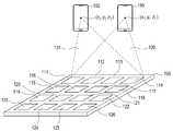
- FIG. 1is a conceptual diagram illustrating a wireless power transmission system according to various embodiments of the present disclosure.
- the apparatus 100 for transmitting power wirelesslymay wirelessly transmit power to at least one electronic device 150 or 160.
- the apparatus 100 for transmitting power wirelesslymay include a plurality of patch antennas 111 to 126.
- the patch antennas 111 to 126are not limited as long as they are each antennas capable of generating an RF wave. At least one of the amplitude and phase of the RF wave generated by the patch antennas 111 to 126 may be adjusted by the wireless power transmitter 100.
- the RF wave generated by each of the patch antennas 111 to 126will be referred to as a sub-RF wave.
- the apparatus 100 for transmitting power wirelesslymay adjust at least one of amplitude and phase of each of the sub-RF waves generated by the patch antennas 111 to 126.
- sub-RF wavesmay interfere with each other. For example, at one point the sub-RF waves may constructively interfere with each other, and at another point the sub-RF waves may cancel each other.
- the sub-RFs from which the patch antennas 111 to 126 are generatedmay cause the sub-RF waves to constructively interfere with each other at the first point (x1, y1, z1). At least one of the amplitude and phase of each of the waves can be adjusted.
- the apparatus 100 for transmitting power wirelesslymay determine that the electronic device 150 is disposed at the first points x1, y1, and z1.
- the position of the electronic device 150may be, for example, a point where the power reception antenna of the electronic device 150 is located.
- the wireless power transmitter 100 determines the position of the electronic device 150will be described later in more detail.
- the apparatus 100 for transmitting power wirelesslymay control the patch antennas 111 to 126 such that the sub-RF waves are constructive interference with each other at the first points x1, y1, and z1.
- controlling the patch antennas 111 to 126means controlling the magnitude of the signal input to the patch antennas 111 to 126 or adjusting the phase (or delay) of the signal input to the patch antennas 111 to 126. It can mean controlling.
- beam formingwhich is a technique for controlling the RF wave to constructively interfere at a specific point.
- various beamforming methodsmay be used, as disclosed in US Patent Publication 2016/0099611, US Patent Publication 2016/0099755, US Patent Publication 2016/0100124, and the like.
- the form of the RF wave formed by beam-formingmay be referred to as pockets of energy.
- the RF wave 130 formed by the sub-RF wavesmay have a maximum amplitude at the first point (x1, y1, z1), and thus the electronic device 150 receives wireless power with high efficiency. can do.
- the apparatus 100 for transmitting power wirelesslymay detect that the electronic device 160 is disposed at the second points x2, y2, and z2.
- the apparatus 100 for transmitting power wirelesslymay control the patch antennas 111 to 126 such that the sub-RF waves are constructive interference at the second points x2, y2 and z2 to charge the electronic device 160.
- the RF wave 131 formed by the sub-RF wavesmay have a maximum amplitude at the second point (x2, y2, z2), and the electronic device 160 may receive wireless power with high transmission efficiency. Can be.
- the electronic device 150may be disposed on the right side.
- the apparatus 100 for transmitting power wirelesslymay apply a relatively larger delay to sub-RF waves formed from patch antennas (eg, 114, 118, 122, 126) disposed on the right side. That is, after the sub-RF waves formed from the patch antennas (for example, 111, 115, 119, 123) disposed on the left side are first formed, the patch antennas (for example, 114, 118, 122, 126) disposed on the right side after a predetermined time passes. A sub-RF wave can be generated from.
- the sub-RF wavesmay meet simultaneously at the point on the right side, that is, the sub-RF waves at the point on the right side may be constructively interfered.
- the wireless power transmission apparatus 100may be substantially connected to the patch antennas (for example, 111, 115, 119, 123) and the patch antennas (for example, 114, 118, 122, 126) on the left side. The same delay can be applied.
- the wireless power transmitter 100may have a patch antenna on the left side (eg, 111, 115, 119, 123) more than a patch antenna on the right side (eg, 114, 118, 122, 126).
- the apparatus 100 for transmitting power wirelesslymay oscillate sub-RF waves substantially simultaneously in the patch antennas 111 to 126, and may perform beam-forming by adjusting a phase corresponding to the above-described delay. It can also be done.
- the apparatus 100 for transmitting powerwirelessly may determine the positions of the electronic devices 150 and 160 and cause the sub-RF waves to become constructive interference at the determined position, thereby performing wireless charging with high transmission efficiency.
- the wireless power transmitter 100may identify the positions of the electronic devices 150 and 160 according to various methods, and may control the conditions for transmitting the RF wave so that constructive interference may occur at the identified positions. .
- performing the specific operation of the wireless power transmitter 100may be included in, for example, the wireless power transmitter 100 (or the electronic device 150). It may mean that the processor performs a specific operation or controls other hardware to perform a specific operation. Alternatively, the wireless power transmitter 100 (or the electronic device 150) performing a specific operation may be, for example, stored in a memory included in the wireless power transmitter 100 (or the electronic device 150). As a stored instruction is executed, it may mean that the processor performs a specific operation or that other hardware performs a specific operation.
- the apparatus 100 for transmitting power wirelesslymay receive a communication signal based on a first communication scheme (eg, BLE communication) from the electronic device 150, and may use the received communication signal.
- a first communication schemeeg, BLE communication
- the apparatus 100 for transmitting power wirelesslymay include a plurality of communication antennas, and accordingly, may determine a direction in which the electronic device 150 is located based on various methods such as TDOA or FDOA.
- the wireless power transmitter 100may check the distance between the wireless power transmitter 100 and the electronic device 150 based on a received signal strength indication (RSSI) of the communication signal.
- RSSIreceived signal strength indication
- the communication signalmay include a transmission strength
- the wireless power transmitter 100may determine a distance between the wireless power transmitter 100 and the electronic device 150 based on the transmission strength of the communication signal and the reception strength of the communication signal. You can check it.
- the communication signalmay include information on a transmission time point.
- the apparatus 100 for transmitting power wirelesslymay check a time of flight (TOF) of the communication signal based on a transmission time of the communication signal and a time at which the communication signal is received, and may use the wireless power transmission device 100 using the same. And the distance between the electronic device 150 and the electronic device 150.
- the apparatus 100 for transmitting power wirelesslymay identify the location of the electronic device 150 based on vision recognition.
- the wireless power transmitter 100may receive information about the location of the electronic device 150 directly from the electronic device 150.
- the electronic device 150may identify its location based at least on various indoor positioning methods (eg, indoor positioning method using geomagnetic map data, indoor positioning method using a signal output from an access point). .
- the electronic device 150may include the location information of the electronic device 150 in the communication signal and transmit the same to the wireless power transmitter 100, so that the wireless power transmitter 100 may transmit the electronic device 150. You can also check the location.
- the apparatus 100 for transmitting power wirelesslymay receive location information of the electronic device 150 from another electronic device that checks locations of nearby devices. Those skilled in the art will readily understand that there is no limitation on the manner in which the wireless power transmitter 100 determines the location of the electronic device 150.
- the apparatus 100 for transmitting power wirelesslymay control at least one of a plurality of phase shifters or a plurality of attenuators so as to form an RF wave corresponding to the position of the electronic device identified according to the various methods described above. .
- FIG. 2Ais a block diagram of a wireless power transmitter and an electronic device according to various embodiments of the present disclosure.
- the apparatus 100 for transmitting power wirelesslymay include at least one of a control circuit 202, a first method communication circuit 203, a memory 205, a power source 206, or a power transmission circuit 209. It may include one.
- the electronic device 150may include a control circuit 252, a first type communication circuit 253, a charger 254, a power management integrated circuit (PMIC) 255, and a memory 256. ), A battery 257, a second type communication circuit 258, or a power receiving circuit 259.
- PMICpower management integrated circuit
- the power transmission circuit 209may transmit power to the power reception circuit 259 wirelessly according to an electromagnetic wave method. That is, the power transmission circuit 209 may form the RF wave 270, and the power receiving circuit 259 may convert the RF wave 270 into electrical energy. Detailed configurations of the power transmission circuit 209 and the power receiving circuit 259 will be described in more detail with reference to FIG. 2B.
- the control circuit 202may control the power source 206 to control the frequency of the source signal generated by the power source 206.
- the control circuit 202may control the frequency of the source signal generated by the power source 206 based on the frequency used by the electronic device 150 by the second type communication circuit 258.
- the second method communication circuit 258 of the electronic device 150communicates with another electronic device (eg, an access point (AP) 280) based on the second method (eg, Wi-fi communication method). can do.
- the second methodeg, Wi-fi communication method
- the Wi-fi communication methodmay use, for example, a frequency band having 5.0 GHz as a center frequency
- the RF wavemay use a frequency band having 5.8 GHz as a center frequency.
- the control circuit 202may determine the frequency of the source signal generated by the power source 206 based on the frequency used by the communication circuit 258 of the second scheme. As one example, the control circuit 202 checks the information on the channel being used by the communication circuit 258 of the second method, and the power source 206 to have a frequency interval corresponding to the channel being used and a frequency interval above the threshold. Can determine the frequency of the source signal.
- the control circuit 252communicates a communication signal including information on a frequency used by the second method communication circuit 258 via the first method communication circuit 253 to communicate with the first method of the wireless power transmitter 100. Transmit to circuit 203.
- the first schememay be at least one of various short-range communication schemes such as, for example, a Bluetooth tooth scheme, a Bluetooth low energy (BLE) scheme, a Wi-Fi direct scheme, and a Zig-bee scheme. There is no limit to the kind.
- the control circuit 202may check the frequency of the second communication method used by the electronic device 150 through the first method communication circuit 203.
- the control circuit 202may determine the frequency of the source signal generated by the power source 206 based at least on the association information between the frequency of the second communication scheme and the frequency of the source signal stored in the memory 205.
- the control circuit 202is based on the received strength (eg, received signal strength indication (RSSI) and data throughput) of the communication signal received by the second mode communication circuit 258, the power source You may determine the frequency of the source signal that 206 generates.
- the electronic device 150transmits the information about the reception strength and the data transmission rate of the communication signal received by the second method communication circuit 258 via the first method communication circuit 253 to the wireless power transmitter. 100 can be transmitted.
- the control circuit 202may determine the frequency of the source signal generated by the power source 206 based at least on the correlation information between the frequency of the source signal for the RSSI-specific data rate stored in the memory 205. You can decide.
- the control circuit 202may transmit power based on the received strength (eg, received signal strength indication (RSSI)) and data throughput of the communication signal received by the second scheme communication circuit 258.
- the transmission strength of the RF wave formed in the circuit 209may be determined.
- the control circuit 202may be configured to determine an RF wave formed in the power transmission circuit 209 based at least on association information between transmission strengths of the RF wave with respect to a data rate per RSSI stored in the memory 205. The transmission strength can be determined.
- the control circuit 202may control the transmission intensity of the RF wave by controlling at least one amplifier circuit included in the power transmission circuit 209.
- the control circuit 202can control the magnitude of the power applied to the power transmission circuit 109 by controlling the magnitude of the bias voltage of the power amplification circuit.
- the control circuit 202may adjust the magnitude of the power output from the power source 206 by controlling the duty cycle or frequency of the power output from the power source 206.
- the control circuit 202may check the position of the electronic device 150 (for example, the position of the power receiving circuit 259) based on the various methods described above, and control the direction in which the RF wave is formed. have.
- the control circuit 202can control the direction in which the RF wave is formed by controlling the phase shifter or the attenuator included in the power transmission circuit 209.
- the control circuit 202 or the control circuit 252is a variety of circuits that can perform operations such as a general purpose processor such as a CPU, a minicomputer, a microprocessor, a micro controlling unit (MCU), a field programmable gate array (FPGA), and the like. It can be implemented, and there is no limit to the kind.
- a general purpose processorsuch as a CPU, a minicomputer, a microprocessor, a micro controlling unit (MCU), a field programmable gate array (FPGA), and the like. It can be implemented, and there is no limit to the kind.
- the power receiving circuit 259may receive power wirelessly from the power transmitting circuit 109 according to an electromagnetic wave method.
- the power receiving circuit 259may perform power processing for rectifying the power of the received AC waveform into a DC waveform, converting a voltage, or regulating the power.
- the PMIC 255may process the received and processed power to be suitable for hardware, and deliver the received power to each hardware.
- the control circuit 252may control the overall operation of the electronic device 150.
- In the memory 256instructions for performing overall operations of the electronic device 150 may be stored.
- the charger 254may charge the battery 257 using the power received from the power receiving circuit 259.
- the memory 205may store instructions for performing an operation of the apparatus 100 for transmitting power wirelessly.
- the memory 250stores information about a communication environment according to the second method of the electronic device 150 (eg, the communication signal of the second method communication circuit 258) received through the first method communication circuit 203. At least one of a frequency, RSSI of a communication signal of the second method communication circuit 258, or a data transmission rate of the second method communication circuit 258), and a transmission condition of an RF wave formed in the power transmission circuit 259 ( For example, at least one of a frequency of an RF wave or a transmission strength of an RF wave may be stored.
- the memory 205 or the memory 256may be implemented in various forms such as read only memory (ROM), random access memory (RAM), or flash memory, and the like.
- 2Bis a detailed block diagram of a power transmission circuit and a power reception circuit according to an electromagnetic wave method according to various embodiments of the present disclosure.
- the power source 206may include a voltage-controlled oscillator (VCO) 211, and a phase looped lock (PLL) circuit 212.
- the power transmission circuit 209may include an amplifier circuit 221, a distribution circuit 222, a phase shifter 223, an amplifier circuit 224, and an antenna array 225 for power transmission.
- the power receiving circuit 259may include an antenna 261 for receiving power, a rectifying circuit 262, and a converting circuit 263.
- the VCO 211may be an oscillator capable of outputting a source signal, and adjust the frequency of the source signal based on the input voltage.
- the VCO 211may be implemented in various forms, such as a linear oscillator, a harmonic oscillator (eg, a crystal oscillator, an LC oscillator), a relaxation oscillator, and the like.
- the PLL circuit 212can detect the phase difference between the input signal and the output signal, control the phase of the VCO 211 by a voltage proportional to this, and control the phase of the output signal to be the same as the phase of the input signal. . Accordingly, the power source 206 may change the frequency of the source signal to be output under external control, and may allow the source signal to have a stable frequency.
- the amplifier circuit 221may amplify a source signal provided from the power source 206 and provide it to the distribution circuit 332.
- the amplifier circuit 331may be implemented by various amplifiers such as a drive amplifier (DA), a high power amplifier (HPA), a Gain Block Amplifier (GBA), or a combination thereof, and the implementation is not limited thereto.
- the distribution circuit 222may distribute the source signal output from the amplifier circuit 221 into a plurality of sub source signals through a plurality of paths.
- the distribution circuit 222is not limited as long as it is a circuit capable of distributing input power or signals in a plurality of paths. For example, the distribution circuit 222 may distribute the source signal in as many paths as the number of patch antennas included in the antenna array 225 for power transmission.
- the phase shifter / attenuator 223may perform at least one of shifting (or delaying) a phase of each of the plurality of AC powers provided from the distribution circuit 222, or controlling amplitudes of each of the plurality of AC powers. have.
- the number of phase shifters / attenuators 223may be plural, for example, the number of patch antennas included in the power transmission antenna array 225.
- the phase shifter / attenuator 223may be implemented by the phase shifter alone, the attenuator alone, or may include both the phase shifter and the attenuator.
- Phase shifter / attenuator 223may include, for example, a phase shifter such as HMC642 or HMC1113.
- At least one of a phase shift degree or an amplitude control degree of each of the phase shifter / attenuator 223may be controlled by the control circuit 202.
- the control circuit 202may determine the position of the electronic device 150, and the RF wave is reinforced by the position of the electronic device 150 (or the position of the power receiving circuit 259 of the electronic device 150).
- At least one of the shifting of the phase of each of the plurality of AC powers, or the control of the amplitudemay be performed so as to interfere, i.e., beam-form.
- the amplifier circuit 224can amplify each of the plurality of AC powers output from the phase shifter / attenuator 223.
- Each of the plurality of patch antennas included in the power transmission antenna array 225may generate sub-RF waves based on the received power.
- the RF wave 270 in which the sub-RF wave is interferedmay be converted into a current, a voltage, or a power by the power reception antenna 261 and output.
- the power reception antenna 261may include a plurality of patch antennas, and may generate current, voltage, or power of an AC waveform by using an RF wave 270 formed around the electromagnetic wave, that is, an electromagnetic wave, and the received power Can be named
- the rectifier circuit 262may rectify the received power into a DC waveform.
- the converting circuit 263may increase or decrease the voltage of the power of the DC waveform to a predetermined value and output the PMIC 255 or the charger 254.
- the control circuit 202may include information about a frequency, information about an RSSI, or a data transmission rate, which are used by the electronic device 150 based on a second type of communication, based on the first type of communication. You can check at least one of the information about.
- the control circuit 202may control at least one of the frequency of the source signal of the VCO 211 or the gain of the amplifying circuit 221 or 224 based on the identified information.
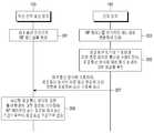
- 3Ais a flowchart illustrating a method of operating a wireless power transmitter and an electronic device according to various embodiments of the present disclosure.
- the apparatus 100 for transmitting power wirelesslymay form an RF wave under a first transmission condition, that is, an initial transmission condition.
- the transmission conditionmay include at least one of the frequency of the RF wave or the transmission strength.
- the apparatus 100 for transmitting power wirelesslyalready checks the position of the electronic device 150, and accordingly assumes that the beam-forming direction of the RF wave has already been confirmed.
- the apparatus 100 for transmitting power wirelesslymay control the VCO 211 to output a source signal of a first frequency, and an amplifier circuit (eg, an amplifier circuit 221 or 224) so that the RF wave has a first transmission strength. You can control the gain of)).
- the transmission conditionmay be expressed by information of the output frequency of the VCO 211 and the gain of the amplifying circuit (eg, the amplifying circuit 221 or 224).
- the apparatus 100 for transmitting power wirelesslymay identify a location of the electronic device 150 in various ways as described above, and may perform RF as a first transmission condition based on the identified location of the electronic device 150. Waves can be formed.
- the first frequency, or first transmission strengthmay be preset.
- the first frequency or the first transmission strengthmay be set based on various information checked by the apparatus 100 for transmitting power wirelessly.
- the wireless power transmitter 100may determine the first transmission condition based on the distance between the wireless power transmitter 100 and the electronic device 150.
- the wireless power transmitter 100may transmit a first transmission condition based on a state of the electronic device 150 (for example, a state of charge of the battery) or information (for example, battery capacity information) of the electronic device 150. Can be determined.
- the wireless power transmission apparatus 100may form a communication connection with the electronic device 150 according to the first scheme.
- the wireless power transmitter 100may establish a BLE connection with the electronic device 150 and transmit a communication signal through the formed BLE link.
- Can send and receiveFor example, the wireless power transmitter 100 may perform a series of procedures for joining the electronic device 150 to a wireless power network managed by the wireless power transmitter 150 through a BLE connection.
- the electronic device 150may convert the RF wave into electrical energy and use it.
- the electronic device 150may check information on a communication environment according to the second communication method while communicating with another electronic device (eg, an AP) based on the second communication method.
- the second communication schememay be, for example, Wi-fi communication.
- the information about the communication environmentmay include information on frequency (or channel information) according to the second communication method, information about the RSSI according to the second communication method, or a data transmission rate according to the second communication method. It may include at least one of information about.
- the electronic device 150may transmit a communication signal including information about a communication environment according to the second communication method, based on the first communication method.
- the electronic device 150may insert information associated with Wi-fi communication into a communication signal based on the BLE scheme and transmit the same.
- An example of a data frame of a communication signalwill be described later in more detail with reference to FIGS. 7A and 7B.
- the apparatus 100 for transmitting power wirelesslymay check information on a communication environment according to the second communication method of the electronic device 150 based on the first communication method.
- the apparatus 100 for transmitting powermay change the transmission condition of the RF wave from the first transmission condition to the second transmission condition based on the received information about the communication environment according to the second communication scheme.
- the wireless power transmitter 100may change the input voltage of the VCO 211 to change the transmission frequency of the RF wave from the first frequency to the second frequency.
- the wireless power transmitter 100may change the gain of the amplifying circuit (for example, the amplifying circuit 221 or 224) so as to change the transmission intensity of the RF wave from the first intensity to the second intensity.
- the apparatus 100 for transmitting power wirelesslymay simultaneously change a frequency and change a transmission strength.
- the apparatus 100 for transmitting power wirelesslymay sequentially change a frequency and a change in transmission strength.
- the apparatus 100 for transmitting power wirelesslymay be set to change a frequency of an RF wave first and then change a transmission intensity.
- the apparatus 100 for transmitting power wirelesslymay continue to receive information on a communication environment according to the second communication method from the electronic device 150 based on the first communication method, and may change the transmission strength according to the corresponding information. .
- 3Bis a flowchart illustrating a method of operating a wireless power transmitter and an electronic device according to various embodiments of the present disclosure.
- the electronic device 150may check information on a communication environment according to the second communication method while communicating with another electronic device based on the second communication method.
- the electronic device 150may transmit a communication signal including information about a communication environment according to the second communication method, based on the first communication method.
- the electronic device 150may form a communication connection with the wireless power transmission device 100 based on the first communication scheme in order to request the wireless power transmission.
- the electronic device 150transmits various communication signals to the wireless power transmitter 100 in order to request the wireless power transmission to the wireless power transmitter 100 or to join the wireless power network managed by the wireless power transmitter 100. ) Can be sent.
- the electronic device 150may insert information about a communication environment according to the second communication scheme into at least one of the aforementioned various communication signals and transmit the information to the wireless power transmitter 100.
- the electronic device 150may transmit information on the communication environment according to the second communication method to a signal for forming a communication connection (eg, an advertisement signal of the BLE communication method) even before the subscription process. You can also insert and send.
- the apparatus 100 for transmitting power wirelesslymay determine a transmission condition of an RF wave based on information on a communication environment according to the received second communication scheme. That is, the apparatus 100 for transmitting power wirelessly may determine an initial transmission condition of an RF wave based on information on a communication environment according to the received second communication scheme. In operation 317, the wireless power transmission apparatus 100 may form an RF wave based on the determined transmission condition.
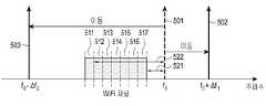
- FIG. 4is a flowchart illustrating a method of operating a wireless power transmitter according to various embodiments of the present disclosure. The embodiment of FIG. 4 will be described in more detail with reference to FIG. 5. 5 illustrates an example of frequency hopping in accordance with various embodiments.
- the wireless power transmission apparatus 100may receive information about a communication environment according to the second communication scheme from the electronic device 150 based on the first communication scheme.
- the apparatus 100 for transmitting powerwirelessly transmits a frequency of a source signal for forming an RF wave or a transmission strength of an RF wave in response to a frequency of a second communication method among pieces of information on a communication environment according to a second communication method. At least one can be determined.
- the wireless power transmitter 100may receive information that a frequency according to the second communication scheme of the electronic device 150 is a third frequency while forming an RF wave at the first frequency.
- the apparatus 100 for transmitting power wirelesslymay determine whether a difference between a first frequency and a third frequency is less than a threshold. If it is determined that the difference between the first frequency and the third frequency is greater than or equal to the threshold, the wireless power transmitter 100 may form an RF wave at the first frequency currently in use. If it is determined that the difference between the first frequency and the third frequency is less than the threshold, the wireless power transmitter 100 may change the frequency of the RF wave from the first frequency to the second frequency.
- the apparatus 100 for transmitting power wirelesslymay identify a second frequency having a difference equal to a third frequency by a threshold.
- the wireless power transmission apparatus 100may directly determine the frequency of the RF wave without calculating a difference based on the third frequency of the second communication scheme used by the electronic device 150.
- the apparatus 100 for transmitting power wirelesslymay determine a second frequency that is a value added to or subtracted from a third frequency.
- the apparatus 100 for transmitting power wirelesslymay directly perform the calculation of the difference or the operation of adding or subtracting a threshold value, or based on a pre-stored selection rule (eg, a lookup table). A second frequency determination operation based on three frequencies may be performed.
- the thresholdmay vary according to various factors.
- the threshold valuemay include various factors such as a distance between the wireless power transmitter 100 and the electronic device 150, the direction of the electronic device 150, the type of electronic device 150 that receives power, and the setting. It may be set separately.
- the apparatus 100 for transmitting power wirelesslymay form an RF wave at a first frequency f0 501, and set the first frequency f0 501 as an initial condition. Can be.
- the apparatus 100 for transmitting power wirelesslymay receive information indicating that the electronic device 150 uses the seventh channel 517 among the channels 511 to 517 of the plurality of Wi-fi.
- the electronic device 150may determine that the difference 521 between the first frequency f0 501 and the seventh channel 517 is less than a threshold value, and thus, the frequency of the RF wave is changed to the second frequency f0 + ⁇ f1. ) 502 or a third frequency (f0- ⁇ f2) 503.
- the apparatus 100 for transmitting powerwirelessly may determine that the difference 522 between the first frequency f0 501 and the first channel 511 is greater than or equal to a threshold value, and accordingly, the first frequency of the RF wave. (f0) 501 may be maintained. Meanwhile, in another embodiment, the apparatus 100 for transmitting power wirelessly may directly determine a change frequency of an RF wave without calculating a difference between a current frequency and a use frequency of the electronic device 150.
- the wireless power transmitter 100may transmit a third frequency f0- ⁇ f2 set corresponding to the seventh channel 517. (503).
- the wireless power transmitter 100may set a second frequency f0 + ⁇ f1 corresponding to the first channel 511. (502) may be confirmed.
- the apparatus 100 for transmitting powerwirelessly may store, for example, association information corresponding to a frequency of an RF wave for each channel of a second communication method, and determine the frequency of the RF wave based on the association information. Meanwhile, in FIG.
- the wireless power transmitter 100forms an RF wave at a first frequency f0 501 and then uses another frequency (for example, a second frequency f0 + ⁇ f1) 502 or a third frequency. (f0- ⁇ f2) 503), but this is merely illustrative.
- the apparatus 100 for transmitting powerwirelessly may receive information about a channel being used by the electronic device 150 and determine an initial frequency of the RF wave before forming the RF wave. .
- the apparatus 100 for transmitting powerwirelessly may form an RF wave having a frequency having a difference greater than or equal to a frequency according to the second communication method of the electronic device 150 from a time point at which the first RF wave is formed. .
- the apparatus 100 for transmitting powerwirelessly adjusts a transmission strength of an RF wave in response to a frequency of a second communication method among information on a communication environment of the electronic device 150 according to a second communication method. It may be. For example, when the difference between the transmission frequency of the wireless power transmission device 100 and the frequency of the second communication scheme of the electronic device 150 is less than the threshold, the wireless power transmission device 100 determines the transmission strength of the RF wave. You can decide to decrease.
- the apparatus 100 for transmitting power wirelesslymay control a power source to generate a source signal having a determined frequency.
- the apparatus 100 for transmitting power wirelesslymay control at least one amplifier to form an RF wave having the determined transmission strength.
- the apparatus 100 for transmitting power wirelesslymay perform one of frequency adjustment, transmission intensity adjustment, or may simultaneously perform frequency adjustment and transmission intensity adjustment. Alternatively, the wireless power transmitter 100 may sequentially perform frequency adjustment and transmission intensity adjustment, and the order of execution is not limited.
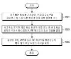
- FIG. 6is a flowchart illustrating a method of operating a wireless power transmitter according to various embodiments of the present disclosure.
- the wireless power transmitter 100may receive information about a communication environment according to the second communication method from the electronic device based on the first communication method.
- the apparatus 100 for transmitting powerwirelessly corresponds to a data transmission rate and a reception strength information of a communication signal according to a second communication method among information on a communication environment according to a second communication method. At least one of a frequency of a source signal for wave formation or a transmission intensity of an RF wave may be determined.
- the apparatus 100 for transmitting powerwirelessly may store association information about a transmission strength of an RF wave according to a data transmission rate for each RSSI of a second communication signal as shown in Table 1 below.
- RSSI of Second Communication SignalData transmission rate of the second communication method RF Wave Transmission Strength Adjustment RSSI_1 Data throughput_1 ⁇ T1 Data throughput_2 ⁇ T2 Data throughput_3 ⁇ T3 Data throughput_4 ⁇ T4 RSSI_2 Data throughput_1 ⁇ T5 Data throughput_2 ⁇ T6 Data throughput_3 ⁇ T7 Data throughput_4 ⁇ T8
- the apparatus 100 for transmitting power wirelesslymay receive the RSSI of the communication signal of the second communication method and the data transmission rate of the second communication method from the electronic device 150 through the first communication method.
- the apparatus 100 for transmitting power wirelesslymay check the degree of adjustment of the transmission intensity of the RF wave by comparing the received information with the related information as shown in Table 1 below.
- the degree of adjustment of the RF wavemay be different according to the RSSI of the communication signal of the second communication method even at the data transmission rate of the same second communication method.
- the apparatus 100 for transmitting power wirelesslymay control a power source to generate a source signal having a determined frequency.
- the apparatus 100 for transmitting power wirelesslymay control at least one amplifier to form an RF wave having the determined transmission strength.
- the apparatus 100 for transmitting power wirelesslymay perform any one of operations 605 and 607. Alternatively, the apparatus 100 for transmitting power wirelessly may simultaneously perform operations 605 and 607. Alternatively, the apparatus 100 for transmitting power wirelessly may perform operations 605 and 607 sequentially, and the order of execution is not limited.
- the apparatus 100 for transmitting power wirelesslymay store association information on the degree of adjustment of the transmission intensity of the RSSI and the RF wave of the communication signal of the second scheme.
- the wireless power transmitter 100may receive information on the RSSI of the communication signal of the second communication method of the electronic device 150 from the electronic device 150 based on the first communication method.
- the apparatus 100 for transmitting power wirelesslymay adjust the transmission strength of an RF wave based on the stored association information and the received information.
- the apparatus 100 for transmitting power wirelesslymay store association information on the data transmission rate of the second communication method and the degree of adjustment of the transmission intensity of the RF wave.
- the wireless power transmitter 100may receive information about the data transmission rate of the second communication method of the electronic device 150 from the electronic device 150 based on the first communication method.
- the apparatus 100 for transmitting powerwirelessly may adjust the transmission strength of an RF wave based on the stored association information and the received information.
- the apparatus 100 for transmitting power wirelesslymay store association information about the RF wave transmission strength itself, rather than the degree of adjustment of the transmission strength of the RF wave according to the various conditions described above, and based on the corresponding association information. It is also possible to determine the transmission strength of the RF wave.
- the apparatus 100 for transmitting power wirelesslydoes not adjust the RF wave transmission strength based on the association information, and adjusts the RF wave transmission strength until the information received from the electronic device 150 satisfies a specified condition. It can also work in a way that adjusts.
- the apparatus 100 for transmitting power wirelesslymay store association information as shown in Table 2 below.
- RSSI of Second Communication SignalMinimum value of data transmission speed of appropriate second communication system RSSI_1 Data throughput_1 RSSI_2 Data throughput_2
- the wireless power transmission apparatus 100may receive, from the electronic device 150, information on the RSSI of the communication signal of the second communication method and the data transmission rate of the second communication method based on the first communication method.
- the apparatus 100 for transmitting powerwirelessly may determine whether the received data transmission rate of the second communication method is greater than or equal to the minimum value of the data transmission rate of the appropriate second communication method according to the related information. If the received data transmission rate of the second communication method is found to be equal to or greater than the minimum value of the data transmission rate of the appropriate second communication method identified in correspondence with the RSSI, the wireless power transmitter 100 determines the transmission strength of the current RF wave. I can keep it.
- the wireless power transmitter 100transmits an RF wave. It is possible to reduce the transmission strength of by a specified size.
- the apparatus 100 for transmitting powerwirelessly subsequently receives information about the RSSI of the communication signal according to the second communication scheme and the data transmission rate of the second communication scheme from the electronic device 150 based on the first communication scheme. Can be.
- the apparatus 100 for transmitting powerwirelessly may reduce the transmission strength of the RF wave until the data transmission rate of the electronic device 150 is equal to or greater than the minimum value of the data transmission rate of the appropriate second communication method.
- the wireless power transmission apparatus 100may store the threshold value of the RSSI of the communication signal of the second communication method, or the threshold value of the data transmission rate of the second communication method. have.
- the apparatus 100 for transmitting power wirelesslymay reduce the transmission strength of the RF wave until the RSSI of the communication signal of the second communication method received based on the first communication method is equal to or greater than a threshold value of the RSSI.
- the apparatus 100 for transmitting power wirelesslymay reduce the transmission strength of the RF wave until the data transmission rate of the second communication scheme received based on the first communication scheme is equal to or greater than a threshold of the data transmission rate. .
- FIG. 7A and 7Billustrate data formats of communication signals according to various embodiments.
- the electronic device 150may periodically or aperiodically transmit a communication signal having the first data format 700 as illustrated in FIG. 7A to the wireless power transmitter 100. . According to various embodiments, the electronic device 150 may transmit a communication signal having the first data format 700 after receiving power from the wireless power transmitter 100.
- the first data format 700may be supported according to, for example, a BLE communication scheme, but there is no limitation on the type of communication scheme supported.
- the first data format 700includes a voltage related information field 701, a current related information field 702, a warning information field 703, a field 704 indicating whether to support Wi-fi related information, and Wi-fi. It may include a related information field 705.
- a voltage value at a predetermined point of the electronic device 150(eg, at least one of an input terminal of the rectifier circuit or an output terminal of the rectifier circuit) may be described.
- a current value at a predetermined point of the electronic device 150(eg, at least one of an input terminal of the rectifier circuit or an output terminal of the rectifier circuit) may be described.
- the apparatus 100 for transmitting powerwirelessly may determine the magnitude of power received by the electronic device 150 based on a value described in the voltage related information field 701 or the current related information field 702, and may use the same. You can also adjust the strength of the RF wave.
- Information about an event occurring in the electronic device 150may be described in the warning information field 703, and the wireless power transmission device 100 may stop wireless charging according to the information described in the warning field 703.
- a value indicating whether the electronic device 150 supports other communication method related informationmay be, for example, in the form of a flag. It may be described.
- the Wi-fi related information field 705for example, information about a Wi-fi frequency (or channel information) that the electronic device 150 is using, information about RSSI of a communication signal according to Wi-fi Or at least one information of a data transmission rate according to Wi-fi.
- the wireless power transmitter 100may receive Wi-fi related information of the electronic device 150 based on BLE, and as described above, a frequency of an RF wave transmitted based on Wi-fi related information, Alternatively, at least one of the transmission strengths may be adjusted.
- the electronic device 150may transmit a communication signal having the second data format 710 as shown in FIG. 7B according to, for example, a broadcasting scheme.
- the second data format 710may be, for example, a data format of an advertisement signal according to BLE communication.
- the WPT service 16-bit UUID field 711for example, identification information of a wireless charging related service may be described.
- the GATT primary service handle field 712may include, for example, attribute handles for various supporting services. The handles may be defined to be numbered in order, for example, from the GATT primary service handle.
- a handle valuemay be defined for an information providing service of another communication method (for example, Wi-Fi) that the electronic device 150 uses, and information associated with a communication method different from the defined value may be defined in the corresponding field ( 712 may be included.
- the RSSI parameter field 713may describe information on the transmission strength of the advertisement signal.
- the ADV flag field 714may include information such as impedance shift, reboot, OVL status, time set support, presence pulse related information, beacon extension request, and the like defined in the AFA standard.
- the field containing information associated with other communication methodseg, Wi-fi
- the apparatus 100 for transmitting power wirelesslymay determine a transmission condition of an initial RF wave based on information associated with another communication scheme (eg, Wi-fi) received from the electronic device 150. Meanwhile, in various embodiments, the apparatus 100 for transmitting power wirelessly may receive a communication signal of the second data format 710 to determine a transmission condition of an initial RF wave, and after charging starts, the first data format 700 may be used. The transmission condition of the RF wave may be adjusted by receiving a communication signal.
- another communication schemeeg, Wi-fi
- FIG. 8is a flowchart illustrating a method of operating a wireless power transmitter and an electronic device according to various embodiments of the present disclosure.
- the wireless power transmitter 100may form an RF wave under a first transmission condition.
- the electronic device 150may convert the RF wave into electrical energy and use it.
- the electronic device 150may check information about a communication environment according to the second communication method while communicating with another electronic device based on the second communication method.
- the information about the communication environmentmay include, for example, at least one of information on frequency, information on RSSI, or information on data transmission rate.
- the electronic device 150may transmit a communication signal including information about a communication environment according to the second communication method, based on the first communication method. For example, the electronic device 150 inserts information on a communication environment according to the second communication method into at least some of the data formats supported by the first communication method, and transmits a communication signal having the corresponding data format.
- the wireless power transmitter 100may transmit the data.
- the apparatus 100 for transmitting powerwirelessly transmits a frequency of a source signal for forming an RF wave or a transmission strength of an RF wave in response to a frequency of a second communication method among information on a communication environment according to a second communication method. At least one can be determined.
- the apparatus 100 for transmitting power wirelesslymay form an RF wave based on at least one of the determined frequency and the transmission strength.
- the electronic device 150may transmit a communication signal including information about a communication environment according to the second communication method, based on the first communication method.
- the apparatus 100 for transmitting powerwirelessly may determine whether data transmission speed and reception strength information of a communication signal according to the second communication scheme satisfy a specified condition.
- the apparatus 100 for transmitting power wirelesslymay store in advance information on a minimum value of an appropriate data transmission rate for each reception intensity information of a communication signal according to a second communication method, and the received data transmission rate may be appropriate for data transmission. You can check whether it is greater than the information about the minimum value of the speed. If it is determined that the specified condition is not satisfied, in operation 815, the apparatus 100 for transmitting power wirelessly may change at least one of a frequency of a source signal or a transmission strength of an RF wave. The apparatus 100 for transmitting power wirelessly may change at least one of a frequency of a source signal or a transmission intensity of an RF wave based on an adjustment degree corresponding to information received through communication, or a numerical value corresponding to information received through communication. Can be.
- the apparatus 100 for transmitting power wirelesslymay change at least one of a frequency of a source signal or a transmission strength of an RF wave based on a numerical value set irrespective of information received through communication.
- the apparatus 100 for transmitting power wirelesslymay receive a communication signal of the first scheme from the electronic device 150 and may repeatedly check whether a specified condition is satisfied. If it is determined that the specified condition is satisfied, in operation 817, the wireless power transmitter 100 may form an RF wave according to the changed transmission condition.
- the wireless power transmitter 100may receive a first communication signal from the electronic device 150 from the electronic device 150 even after operation 817. If it is determined that the designated condition is not satisfied, the wireless power transmitter 100 may change the transmission condition of the RF wave.
- 9Ais a flowchart illustrating a method of operating a wireless power transmitter and an electronic device according to various embodiments of the present disclosure.
- the wireless power transmitter 100may form an RF wave under a first transmission condition.
- the apparatus 100 for transmitting power wirelesslyis based on, for example, an RF wave based on various information such as the location of the electronic device 150 with respect to the apparatus 100 for transmitting power and information on the state of the electronic device 150.
- the initial transmission condition ofmay be determined.
- the apparatus 100 for transmitting power wirelesslymay form an RF wave 900 with a transmission strength of A.
- the electronic device 150may convert the RF wave into electrical energy and use it.
- the electronic device 150may check information on a communication environment according to the second communication method while communicating with another electronic device based on the second communication method.
- the electronic device 150may transmit a communication signal including information about the communication environment according to the second communication scheme to the wireless power transmitter 100 based on the first communication scheme.
- the apparatus 100 for transmitting power wirelesslymay change a transmission frequency of an RF wave based on information about a communication environment according to the received second communication scheme. For example, the apparatus 100 for transmitting power wirelessly may set a transmission frequency of an RF wave so as to have a difference greater than a specified threshold and a frequency of the received second communication scheme. In this case, the apparatus 100 for transmitting power wirelessly may form an RF wave 901 having a frequency changed while having a transmission strength of A.
- the electronic device 150may transmit a communication signal including information about a communication environment according to the second communication method, based on the first communication method.
- the apparatus 100 for transmitting power wirelesslymay reduce transmission strength of an RF wave based on information about a communication environment according to the received second communication scheme. For example, the apparatus 100 for transmitting power wirelessly may determine that information on a communication environment according to the second communication method does not satisfy a specified condition, and correspondingly, may reduce a transmission strength of an RF wave.
- the apparatus 100 for transmitting power wirelesslymay form an RF wave 902 having a size of B.
- the electronic device 150may transmit a communication signal including information about a communication environment according to the second communication method, based on the first communication method.
- the apparatus 100 for transmitting power wirelesslymay increase the transmission strength of the RF wave based on the information about the communication environment according to the received second communication scheme.
- the apparatus 100 for transmitting power wirelesslymay increase the transmission strength of the RF wave when it is determined that the information on the communication environment according to the second communication scheme satisfies a specified condition.
- the apparatus 100 for transmitting power wirelesslymay form an RF wave 903 having a size of C.
- the wireless power transmitter 100may decrease the transmission strength of the RF wave again. .
- the apparatus 100 for transmitting powerwirelessly may be configured to specify information on a communication environment according to the received second communication scheme. If it is confirmed to satisfy, may be set to maintain the current transmission conditions.
- 9Bis a flowchart illustrating a method of operating a wireless power transmitter and an electronic device according to various embodiments of the present disclosure.
- the electronic device 150may check information on a communication environment according to the second communication method while communicating with another electronic device based on the second communication method.
- the electronic device 150may transmit a communication signal including information about a communication environment according to the second communication scheme to the wireless power transmitter 100 based on the first communication scheme.
- the electronic device 150may transmit a communication signal including information on a communication environment according to the second communication scheme before receiving the RF wave from the wireless power transmitter 100.
- the electronic device 150may be connected to a communication signal used to establish a communication connection with the wireless power transmitter 100 or a power network managed by the wireless power transmitter 100.
- information on the communication environment according to the second communication schememay be included and transmitted.
- the apparatus 100 for transmitting powermay determine a transmission condition of an RF wave based on information about a communication environment according to the received second communication scheme.
- the apparatus 100 for transmitting power wirelesslymay form an RF wave based on the determined transmission condition, and may, for example, form an RF wave 930 having a transmission strength of A.
- the wireless power transmitter 100may control the power source so that the frequency of the RF wave 930 to be formed has a difference between the frequency of the second communication method used by the electronic device 150 and the specified threshold or more. Can be.
- the electronic device 150may transmit a communication signal including information about a communication environment according to the second communication method, based on the first communication method.
- the apparatus 100 for transmitting power wirelesslymay reduce the transmission strength of the RF wave based on the information about the communication environment according to the received second communication scheme.
- the apparatus 100 for transmitting power wirelesslymay reduce the transmission strength of the RF wave as it determines that the information on the communication environment according to the received second communication method does not satisfy a specified condition.
- the apparatus 100 for transmitting power wirelesslymay form an RF wave 931 having a transmission strength of B.
- the electronic device 150may transmit a communication signal including information about a communication environment according to the second communication method, based on the first communication method.
- the apparatus 100 for transmitting power wirelesslymay increase the transmission strength of the RF wave based on the information about the communication environment according to the received second communication scheme.
- the apparatus 100 for transmitting power wirelesslymay form an RF wave 932 having a transmission strength of C, for example. If it is determined that the information on the communication environment according to the second communication method does not satisfy the specified condition through the received communication signal, the wireless power transmitter 100 may decrease the transmission strength of the RF wave again. .
- the apparatus 100 for transmitting power wirelesslymay be configured to specify information on a communication environment according to the received second communication scheme. If it is confirmed to satisfy, may be set to maintain the current transmission conditions.
- FIG. 10is a flowchart illustrating a method of operating a wireless power transmitter, an electronic device, and a server, according to various embodiments.
- the server 1000may generate a transmission condition selection model of an RF wave for a communication environment according to the second communication scheme, based on the obtained database.
- the server 1000may include a communication module capable of communicating with at least one of the wireless power transmitter 100 or the electronic device 150, and a processor capable of generating a transmission condition selection model of an RF wave. , And a memory capable of storing the obtained database.
- the server 1000may receive, from the wireless power transmitter 100 or another wireless power transmitter, information on a transmission condition of an RF wave and a communication environment according to a second communication method of the electronic device 150. have.
- the apparatus 100 for transmitting powerwirelessly may determine a training condition selection model of an RF wave trained using information on a transmission condition of an RF wave and a communication environment according to a second communication method of the electronic device 150. Can be generated.
- the transmission condition selection model of the RF wavemay be a rule-based model or an artificial intelligence model trained according to at least one of machine learning, neural networks, or deep learning algorithms.
- the server 1000may transmit the selection model to the wireless power transmitter 100.
- the selection modelmay include, for example, at least one factor of the communication environment according to the second communication scheme (eg, frequency of the second communication scheme, RSSI of the communication signal according to the second communication scheme, or data transmission rate of the second communication scheme).
- at least one of a transmission conditioneg, at least one of a transmission frequency of the RF wave or a transmission intensity of the RF wave
- the electronic device 150may check information on a communication environment according to the second communication method while communicating with another electronic device based on the second communication method.
- the electronic device 150may transmit a communication signal including information about a communication environment according to the second communication method, based on the first communication method.
- the apparatus 100 for transmitting powerwirelessly may determine a transmission condition of an RF wave based on a selection model and information on a communication environment according to the received second communication scheme.
- the apparatus 100 for transmitting powerwirelessly may input information about a communication environment according to the second communication method of the received electronic device 150 as an input value of the selection model.
- the wireless power transmitter 100may check the transmission condition of the RF wave which is an output value of the selection model.
- the apparatus 100 for transmitting power wirelesslymay form an RF wave based on the determined transmission condition.
- the electronic device 150may transmit a communication signal including information about a communication environment according to the second communication method, based on the first communication method.
- the apparatus 100 for transmitting power wirelesslymay check information about a communication environment according to the changed second communication method.
- the apparatus 100 for transmitting power wirelesslymay transmit information about a communication condition according to a transmission condition of an RF wave and a changed second communication scheme to the server 1000.
- the server 1000may update the model based on the received information.
- the server 1000may transmit the updated model to the wireless power transmitter 100.
- the server 1000may receive a database from the wireless power transmitter 100 as well as another wireless power transmitter, and may update based on the database.
- the server 1000may be configured such as a relative position of the electronic device 150 based on the wireless power transmitter 100, state information of the electronic device 150, a model of the electronic device 150, and the like. You can also manage selection models by information.
- the wireless power transmitter 100transmits information such as the determined relative position, the state information of the electronic device 150, the model of the electronic device 150, and the like to the server 1000, and provides a corresponding selection model. May be received.
- the wireless power transmitter 100may transmit information about the communication environment of the second communication method received from the electronic device 150 to the server 1000, and the server 1000 may receive the received second communication.
- the RF wave transmission condition corresponding to the information about the communication environment of the schememay be transmitted to the wireless power transmitter 100.
- FIG. 11is a flowchart illustrating a method of operating a wireless power transmitter and an electronic device according to various embodiments of the present disclosure.
- the wireless power transmitter 100may form an RF wave under a first transmission condition.
- the electronic device 150may convert the RF wave into electrical energy and use it.
- the electronic device 150may check information on a communication environment according to the second communication method while communicating with another electronic device based on the second communication method.
- the electronic device 150may transmit a communication signal including information about a communication environment according to the second communication method, based on the first communication method.
- the apparatus 100 for transmitting power wirelesslymay change a transmission frequency of an RF wave based on information on a communication environment according to the received second communication scheme.
- the electronic device 150may transmit a communication signal including information about a communication environment according to the second communication method, based on the first communication method.
- the apparatus 100 for transmitting powerwirelessly may determine that the RSSI and the data transmission rate of the second communication method of the electronic device 150 do not satisfy a specified condition.
- the wireless power transmitter 100may transmit a signal to the electronic device 150 requesting a change in the communication condition of the second communication method.
- the electronic device 150may change a communication condition of the second communication method. For example, the electronic device 150 may transmit and receive a communication signal with the AP to change the operating frequency.
- FIG. 12is a flowchart illustrating a method of operating a wireless power transmitter, an electronic device, and an AP according to various embodiments of the present disclosure.
- the apparatus 100may establish a communication connection based on a second communication scheme.
- the apparatus 100 for transmitting power wirelesslymay include a first method communication module capable of communicating with the electronic device 150 and a second method communication module capable of communicating with the AP 1200. It may be.
- the apparatus 100 for transmitting power wirelesslymay determine a frequency range for forming an RF wave.
- the apparatus 100 for transmitting power wirelesslymay transmit the determined frequency range to the AP 1200.
- the AP 1200may identify an RF wave formable frequency range and a frequency range for the second communication scheme.
- the AP 1200may determine an RF wave formable frequency range so that interference between the RF wave and the communication signal of the second communication method may be minimized, and correspondingly, may also determine a frequency range for the second communication method.
- the AP 1200may transmit an RF wave formable frequency range to the wireless power transmitter 100.
- the AP 1200may form a communication connection based on a frequency within a frequency range for the second communication scheme.
- the wireless power transmitter 100may form a communication connection based on the first communication scheme.
- the apparatus 100 for transmitting powerwirelessly may form an RF wave based on a frequency within a received RF wave formable frequency range. Accordingly, interference between the RF wave and the communication signal of the second communication scheme can be minimized.
- the AP 1200is shown as determining the transmission frequency range of the RF wave, the frequency range for the second communication scheme, but this is merely exemplary.
- the wireless power transmitter 100may determine a transmission frequency range of an RF wave, a frequency range for a second communication scheme, and transmit a frequency range for the second communication scheme to the AP 1200. It may be.
- the wireless power transmitter 100may perform communication through the relay of the electronic device 150.
- the electronic device 150may be configured to perform transcoding between the communication signal of the first communication method and the communication signal of the second communication method.
- FIG. 13is a flowchart illustrating a method of operating a wireless power transmitter and an electronic device according to various embodiments of the present disclosure. The embodiment of FIG. 13 will be described in more detail with reference to FIG. 14. 14 illustrates an electronic device according to various embodiments of the present disclosure.
- the wireless power transmitter 100may form an RF wave under a first transmission condition.
- the electronic device 150may convert the RF wave into electrical energy and use it.
- the electronic device 150may check information on a communication environment according to the second communication method while communicating with another electronic device based on the second communication method.
- the electronic device 150may transmit a communication signal including information about a communication environment according to the second communication method, based on the first communication method.
- the apparatus 100 for transmitting powerwirelessly may change a transmission frequency of an RF wave based on information about a communication environment according to the received second communication scheme.
- the wireless power transmitter 100may transmit the frequency change completion information of the RF wave to the electronic device 150.
- the electronic device 150may determine that the RSSI and the data transmission rate do not satisfy the specified condition.
- the electronic device 150may provide a UI for selecting priority among wireless charging and the second communication scheme. For example, as shown in FIG. 14, the electronic device 150 may display a UI 1400 for priority selection.
- the UI 1400 for priority selectionmay include a message 1401 for selecting a priority, a wireless charging selection button 1402, or a second communication method (eg, Wi-fi) selection button 1403. .
- the electronic device 150may determine whether wireless charging is selected to have priority. For example, the electronic device 150 may determine whether the wireless charging selection button 1402 of the UI 1400 is selected or the second communication method selection button 1403 is selected. If it is determined that the second communication scheme is selected to have a priority, in operation 1319, the electronic device 150 may request to decrease the transmission strength of the RF wave. Upon receiving the request for reducing the transmission strength of the RF wave, the wireless power transmission apparatus 100 may reduce the transmission strength of the RF wave in operation 1321. When it is determined that the wireless charging is selected to have priority, the electronic device 150 may change the channel of the second communication scheme or perform communication according to the current channel in operation 1323.
- 15is a flowchart illustrating a method of operating a wireless power transmitter according to various embodiments of the present disclosure.
- the wireless power transmitter 100may receive information about a communication environment according to the second communication method from the electronic device 150 based on the first communication method.
- the apparatus 100 for transmitting powerwirelessly may determine a transmission path of an RF wave in response to a frequency of the second communication method among information on the communication environment according to the second communication method.
- the apparatus 100 for transmitting powerwirelessly may store association information between information on a communication environment according to a second communication method and a transmission path of an RF wave.
- the apparatus 100 for transmitting powerwirelessly may determine a transmission path of an RF wave based on the stored association information.
- the wireless power transmission apparatus 100may control each of the plurality of phase shifters to form an RF wave according to the determined transmission path.
- 16is a block diagram of an external electronic device and an electronic device according to various embodiments of the present disclosure.
- an external electronic device 1600may include a wireless power transmitter 1610 and an AP 1620.
- the wireless power transmitter 1610may include at least some of the components included in the wireless power transmitter 100 of FIG. 2A.
- the AP 1620may transmit / receive a communication signal 1631 with the electronic device 150 based on a second communication method (for example, Wi-fi communication method).
- the wireless power transmitter 1610 and the AP 1620may be implemented as one external electronic device 1600.
- the wireless power transmitter 1610 and the AP 1620may be included in the housing, and may be connected by wire to transmit and receive data.
- the wireless power transmission device 1601 and the AP 1620are not disposed in one housing, but may be implemented by wired connection to transmit and receive data.
- the wireless power transmitter 1610may include, for example, a communication circuit based on a first communication scheme (eg, a Bluetooth communication circuit), and the communication signal 1632 based on the first communication scheme with the electronic device 150. You can also send and receive.
- a communication circuit based on the first communication schememay not be included in the wireless power transmitter 1610, in which case the wireless power transmitter 1610 may be based on information received through the AP 1620. May control power transmission.
- the wireless power transmitter 1610may form an RF wave 1640, and the electronic device 150 may convert the formed RF wave 1640 into electrical energy.
- the external electronic device 1600may perform wireless charging by simultaneously forming an RF wave 1640 while communicating with the electronic device 150 based on the second communication method. It may be.
- 17Ais a flowchart illustrating an external electronic device and an operating method of the electronic device according to various embodiments of the present disclosure.
- the external electronic device 1600may form an RF wave under a first transmission condition.
- the external electronic device 1600may form an RF wave under a first transmission condition by using the wireless power transmitter 1610 included therein.
- the wireless power transmitter 1610may identify the location of the electronic device 150, for example, and form an RF wave based on the first transmission condition.
- the electronic device 150may convert the RF wave into electrical energy and use it.
- the external electronic device 1600may check information about a communication environment according to the second communication method.
- the external electronic device 1600may check the information on the communication environment according to the second communication method by using the AP 1620 including.
- the AP 1620may check information on a communication environment according to the second communication method, based on the communication signal received from the electronic device 150.
- the external electronic device 1600transmits a frequency or RF wave of a source signal for forming an RF wave in response to the reception intensity information of the communication signal received from the electronic device 1500 and the data transmission rate according to the second communication method. At least one of the intensities can be determined. Since the process of changing the transmission condition of the RF wave based on the received communication signal has been described in detail above, further description thereof will be omitted.
- the external electronic device 1600may change the transmission condition of the RF wave from the first transmission condition to the second transmission condition based on the information on the communication environment according to the second communication method.
- the electronic device 150may convert the RF wave into electrical energy and use it.
- the external electronic device 1600may change a communication condition (eg, a communication frequency or a communication channel) of the AP 1620 based on the information about the communication environment according to the second communication method. For example, the external electronic device 1600 may change the communication frequency (or communication channel) of the AP 1620 such that a difference between the frequency of the RF wave and the communication frequency of the AP 1620 is equal to or greater than a specified value. .
- a communication conditioneg, a communication frequency or a communication channel
- 17Bis a flowchart illustrating an external electronic device and an operating method of the electronic device according to various embodiments of the present disclosure.
- the external electronic device 1600may form an RF wave under the first transmission condition.
- the electronic device 150may convert the RF wave into electrical energy and use it.
- the electronic device 150may transmit a communication signal including information about a communication environment according to the second communication method. For example, as in operation 307 of FIG. 3A, the electronic device 150 may transmit a communication signal including information about a communication environment according to the second communication method.
- the external electronic device 1600may change the transmission condition of the RF wave from the first transmission condition to the second transmission condition based on the information on the communication environment according to the second communication scheme.
- the electronic device 150may convert the RF wave into electrical energy and use it.
- the external electronic device 1600controls the AP 1620 based on the information on the communication environment according to the second communication method, thereby communicating a communication condition (eg, a communication frequency, Or communication channel).
- a communication conditioneg, a communication frequency, Or communication channel
- the external electronic device 1600may be included in an analysis result (eg, reception strength of the communication signal, data throughput) of the communication signal received according to the second communication method, and included in the communication signal according to the first communication method.
- an analysis resulteg, reception strength of the communication signal, data throughput
- At least one of a transmission condition of an RF wave or a communication condition of a second communication method using all of informationfor example, a reception strength of a communication signal received by the electronic device 150 and data throughput measured by the electronic device 150. You can also adjust.
- 17Cis a flowchart illustrating an external electronic device and an operating method of the electronic device according to various embodiments of the present disclosure.
- the external electronic device 1600may form an RF wave under the first transmission condition.
- the electronic device 150may convert the RF wave into electrical energy and use it.
- the electronic device 150may request a communication connection according to the second communication method. For example, the electronic device 150 may search for the AP 1620 included in the external electronic device 1600 and request a communication connection to the discovered AP 1620 based on automatic or user input. Can be.
- the external electronic device 1600may change the transmission condition of the RF wave from the first transmission condition to the second transmission condition based on at least one parameter associated with the second communication scheme.
- the external electronic device 1600may change the transmission condition of the RF wave from the first transmission condition to the second transmission condition based on the communication frequency of the second communication method.
- the external electronic device 1600may change the transmission frequency of the RF wave so that the transmission frequency of the RF wave has a difference equal to or greater than a specified value from the communication frequency of the second communication method.
- the electronic device 150may convert the RF wave into electrical energy and use it.
- the external electronic device 1600may determine the parameter of the second communication scheme based on a transmission condition of an RF wave that is already being performed.
- the external electronic device 1600may determine, for example, the communication frequency (or communication channel) of the second communication method such that the transmission frequency of the RF wave is equal to or greater than a specified value of the communication frequency of the second communication method. .
- 17Dis a flowchart illustrating an external electronic device and an operating method of the electronic device according to various embodiments of the present disclosure.
- the external electronic device 1600 and the electronic device 150may establish a communication connection according to a second communication method to perform data transmission and reception.
- the electronic device 150may search for the AP 1620 included in the external electronic device 1600, and establish a communication connection with the discovered AP 1620 based on automatic or user selection. Can be formed.
- the electronic device 150may request wireless power transmission from the external electronic device 1600 or the wireless power transmission device 1610.
- the electronic device 150may request the wireless power transmission device 1610 to transmit wireless power based on the first communication scheme.
- the electronic device 150may request the wireless power transmission from the AP 1620 based on the second communication scheme.
- the external electronic device 1600may identify a transmission condition of the RF wave based on at least one parameter associated with the second communication scheme, and form an RF wave based on the confirmed transmission condition. For example, the external electronic device 1600 may determine the transmission frequency of the RF wave so that the communication frequency of the second communication method is different from the communication frequency. In operation 1737, the electronic device 150 may convert the RF wave into electrical energy and use it.
- the external electronic device 1600may change a parameter of the second communication scheme based on a transmission condition of an RF wave that is already being performed.
- the external electronic device 1600may change the communication frequency (or communication channel) of the second communication method so that, for example, the transmission frequency of the RF wave is greater than or equal to a specified value of the communication frequency of the second communication method. .
- FIG. 18is a flowchart illustrating a method of operating a wireless power transmitter and an electronic device according to various embodiments of the present disclosure.
- the wireless power transmitter 100may transmit a beacon signal.
- the wireless power transmitter 100may transmit a beacon signal in various directions.
- the apparatus 100 for transmitting powerwirelessly may form a beacon signal, that is, an RF wave, based on a predetermined steering direction change rule. Accordingly, the electronic device 150 disposed near the wireless power transmitter 100 may receive a beacon signal.
- the electronic device 150may activate a communication circuit of a first communication method based on the received beacon.
- the beacon signalis a communication circuit of the first method (for example, communication circuit 253 of the first method) in the electronic device 150 is turned on to transmit a predetermined communication signal (for example, advertisement signal).
- a predetermined communication signalfor example, advertisement signal.
- the electronic device 150may turn on the first type communication circuit 253 using power from the battery 257 in the electronic device 150.
- the electronic device 150may include a magnitude of power received by the power receiving circuit 259 (eg, at least one of the magnitude of the voltage or current of at least one of the rectifier input terminal or the output terminal, or the output terminal of the DC / DC converter).
- the first method communication circuit 253may be turned on. That is, the electronic device 150 may turn on the first type communication circuit 253 when the magnitude of the received power indicates the magnitude corresponding to the reception of the beacon signal.
- the beacon signalmay include specified information, and the electronic device 150 may receive the beacon signal and check the included specified information. The electronic device 150 may turn on the first type communication circuit 253 based on the confirmation of the designated information.
- the electronic device 150may transmit a communication signal through a communication circuit of a first communication method.
- the wireless power transmitter 100may detect the electronic device 150 based on the received communication signal.
- the wireless power transmission apparatus 100receives a designated communication signal (eg, an advertisement signal) within a preset time, and then detects that the electronic device 150 is detected. It can be confirmed that.
- the wireless power transmitter 100determines that a designated communication signal is received within a preset time after forming the beacon signal, and the strength of the received communication signal is greater than or equal to a threshold value, the electronic device 150 detects it. It can also be confirmed.
- the wireless power transmitter 100 and the electronic device 150may perform a procedure required for wireless power transmission.
- the wireless power transmission apparatus 100may form a communication connection (eg, a BLE connection) with the electronic device 150.
- the wireless power transmitter 100 and the electronic device 150may exchange communication signals including respective product information, and the wireless power transmitter 100 may wirelessly transmit the electronic device 150 through a corresponding process.
- the power transmission apparatus 100may subscribe to a power network managed by the power transmission apparatus 100.
- the wireless power transmitter 100may form an RF wave for charging.
- the electronic device 150may convert the RF wave into electrical energy and use it.
- the wireless power transmitter 100may transmit a beacon signal at a first beam width.
- the first beam widthmay be set greater than the second beam width of the RF wave for later charging.
- 19is a flowchart illustrating a method of operating a wireless power transmitter, an electronic device, and an AP according to various embodiments of the present disclosure.
- the AP 280may establish a communication connection with the electronic device 150 based on the second communication scheme.
- the AP 280may transmit information indicating that the wireless power transmitter 100 exists to the electronic device 150.
- the AP 280may check information indicating that the wireless power transmitter 100 exists based on an external input at the time of installation or communication with the wireless power transmitter 100 later.
- the AP 280may transmit a communication signal including information indicating that the wireless power transmitter 100 exists to the electronic device 150.
- the AP 280may include information indicating that the wireless power transmitter 100 exists in various communication signals and transmit the information, and the AP 280 may include information indicating that the wireless power transmitter 100 exists. There is no limit to the kind.
- the electronic device 150may transmit a communication circuit of the first communication method (eg, a communication circuit of the first communication method) based on the information indicating that the received wireless power transmitter 100 exists.
- the communication circuit 258 of the first communication methodmay be activated.
- the electronic device 150transmits a communication signal to the wireless power transmitter 100 through the communication circuit 258 of the first communication method.
- the wireless power transmitter 100may detect the electronic device 150 based on the received communication signal in operation 1909.
- the wireless power transmitter 100 or the electronic device 150may detect the electronic device 150. At least one of may perform a procedure required for wireless power transmission in operation 1911.
- the wireless power transmission apparatus 100may form an RF wave, and in operation 1915, the electronic device ( 150 may convert and use an RF wave into electrical energy.
- 20is a flowchart illustrating an external electronic device and an operating method of the electronic device according to various embodiments of the present disclosure.
- the external electronic device 1600 and the electronic device 150may form a communication connection based on the second communication scheme.
- the external electronic device 1600transmits information indicating that the wireless power transmission device exists, that is, information indicating that the external electronic device 1600 can perform wireless power transmission to the electronic device 150. can do.
- the external electronic device 1600may transmit a communication signal including information indicating that the wireless power transmitter exists to the electronic device 150 through the AP 1620 including the wireless power transmitter. There is no restriction
- the electronic device 150may activate a communication circuit of a first communication scheme based on information indicating that a wireless power transmission device exists.
- the electronic device 150may transmit a communication signal through a communication circuit of a first communication method.
- the external electronic device 1600may detect the electronic device 150 based on the received communication signal. At least one of the external electronic device 1600 or the electronic device 150 may perform a procedure required for wireless power transmission in operation 2011.
- the external electronic device 1600may form an RF wave.
- the electronic device 150may convert the RF wave into electrical energy and use it.
- Various embodiments of this documentmay include software (eg, a program) that includes instructions stored on a machine-readable storage medium (eg, internal memory or external memory) that can be read by a machine (eg, a computer). It can be implemented as.
- the deviceis a device capable of calling a stored command from a storage medium and operating according to the called command, wherein the device includes at least one of an electronic device (eg, the wireless power transmitter 100 or the electronic device 150) according to the disclosed embodiments.
- the instructionis executed by a processor (eg, at least one of the control circuit 202, or the control circuit 252), the processor may function directly or in response to the instruction using other components under the control of the processor. Can be performed.
- the instructionscan include code generated or executed by a compiler or interpreter.
- the device-readable storage mediummay be provided in the form of a non-transitory storage medium.
- 'non-temporary'means that the storage medium does not include a signal and is tangible, and does not distinguish that data is stored semi-permanently or temporarily on the storage medium.
- a methodmay be provided included in a computer program product.
- the computer program productmay be traded between the seller and the buyer as a product.
- the computer program productmay be distributed online in the form of a device-readable storage medium (eg compact disc read only memory (CD-ROM)) or through an application store (eg Play StoreTM).
- a device-readable storage mediumeg compact disc read only memory (CD-ROM)
- an application storeeg Play StoreTM
- at least a portion of the computer program productmay be stored at least temporarily on a storage medium such as a server of a manufacturer, a server of an application store, or a relay server, or may be temporarily created.
- Each componenteg, a module or a program
- some componentseg, modules or programs
- operations performed by a module, program, or other componentmay be executed sequentially, in parallel, repeatedly, or heuristically, or at least some of the operations may be executed in a different order, omitted, or another operation may be added. Can be.
Landscapes
- Engineering & Computer Science (AREA)
- Computer Networks & Wireless Communication (AREA)
- Power Engineering (AREA)
- Charge And Discharge Circuits For Batteries Or The Like (AREA)
Abstract
Description
Translated fromKorean다양한 실시예는 무선 전력 송신 장치 및 전력을 무선으로 수신하는 전자 장치와 그 동작 방법에 관한 것으로, 더욱 상세하게는 서로 통신을 수행할 수 있는 무선 전력 송신 장치 및 전력을 무선으로 수신하는 전자 장치와 그 동작 방법에 관한 것이다.Various embodiments of the present disclosure relate to a wireless power transmitter and an electronic device for wirelessly receiving power, and a method of operating the same, and more particularly, to a wireless power transmitter and an electronic device for wirelessly receiving power. It relates to the operation method.
현대를 살아가는 많은 사람들에게 휴대용 디지털 통신기기들은 하나의 필수 요소가 되었다. 소비자들은 언제 어디서나 자신이 원하는 다양한 고품질의 서비스를 제공받고 싶어한다. 뿐만 아니라 최근 IoT (Internet of Thing)로 인하여 우리 생활 속에 존재하는 각종 센서, 가전기기, 통신기기 등은 하나로 네트워크화 되고 있다. 이러한 각종 센서들을 원활하게 동작시키기 위해서는 무선 전력 송신 시스템이 필요하다.For many people in modern times, portable digital communication devices have become an essential element. Consumers want to be provided with various high quality services they want anytime and anywhere. In addition, due to the IoT (Internet of Thing), various sensors, home appliances, and communication devices that exist in our lives are being networked into one. In order to operate the various sensors smoothly, a wireless power transmission system is required.
무선 전력 송신은 자기유도, 자기공진, 그리고 전자기파 방식이 있다. 자기유도 또는 자기공진 방식은, 무선 전력 송신 장치에 상대적으로 근거리에 위치한 전자 장치를 충전하는데 유리하다. 전자기파 방식은, 자기유도 또는 자기 공진 방식에 수 m에 이르는 원거리 전력 전송에 보다 유리하다. 전자기파 방식은 주로 원거리 전력 전송에 사용되며, 원거리에 있는 전력 수신기의 정확한 위치를 파악하여 전력을 가장 효율적으로 전달할 수 있다.Wireless power transmission includes magnetic induction, magnetic resonance, and electromagnetic waves. Magnetic induction or magnetic resonance is advantageous for charging an electronic device located at a relatively short distance from a wireless power transmission device. The electromagnetic wave method is more advantageous for long distance power transmission of several m to the magnetic induction or the magnetic resonance method. Electromagnetic wave method is mainly used for long distance power transmission, and can locate power receiver in remote place and transmit power most efficiently.
전자기파 방식에 기반하여 전력을 무선으로 수신하는 전자 장치는, 무선 전력 송신 장치로부터 형성된 RF(radio frequency) 웨이브(wave)를 전기적인 에너지로 변환함으로써 무선으로 전력을 수신할 수 있다. 한편, 전자 장치는, 다른 전자 장치와 통신을 수행할 수 있다. 이 경우, RF 웨이브의 주파수와, 다른 전자 장치와의 통신을 위한 주파수가 근접한 경우, RF 웨이브와 통신 신호가 서로 간섭이 될 수 있다. RF 웨이브 및 통신 신호의 간섭에 의하여, 통신 신호의 데이터 전송 속도(data throughput)이 저하되거나, 또는 무선 충전의 효율이 저하될 수 있다.An electronic device that wirelessly receives power based on an electromagnetic wave method may receive power wirelessly by converting a radio frequency (RF) wave formed from the wireless power transmitter into electrical energy. Meanwhile, the electronic device may communicate with another electronic device. In this case, when the frequency of the RF wave and the frequency for communication with other electronic devices are close to each other, the RF wave and the communication signal may interfere with each other. Due to the interference of the RF wave and the communication signal, the data throughput of the communication signal may be lowered, or the efficiency of wireless charging may be lowered.
다양한 실시예는, 다른 전자 장치와 통신을 수행하는 전자 장치로부터 해당 통신 환경에 대한 정보를 수신하고, 수신된 통신 환경에 대한 정보에 기반하여 RF 웨이브의 송신 조건을 제어할 수 있는 무선 전력 송신 장치 및 그 동작 방법을 제공할 수 있다. 아울러, 다양한 실시예는, 다른 전자 장치와의 통신 환경에 대한 정보를, 무선 전력 송신 장치로 송신하는 전자 장치 및 그 동작 방법을 제공할 수 있다.According to various embodiments of the present disclosure, a wireless power transmitter capable of receiving information about a corresponding communication environment from an electronic device communicating with another electronic device and controlling a transmission condition of an RF wave based on the received information about the communication environment And a method of operating the same. In addition, various embodiments may provide an electronic device for transmitting information about a communication environment with another electronic device to a wireless power transmitter and an operation method thereof.
다양한 실시예에 따라서, 무선 전력 송신 장치는, 제 1 방식 통신 회로, 소스 신호를 발생시키는 전력 소스, 상기 소스 신호에 기초하여 RF 웨이브를 형성하는 전력 송신 회로, 및 제어 회로를 포함하고, 상기 제어 회로는, 상기 제 1 방식 통신 회로를 통하여, 제 1 방식의 통신 및 제 2 방식의 통신을 지원하는 전자 장치로부터, 상기 제 2 방식의 통신에 따른 통신 환경에 대한 정보를 포함하는 통신 신호를 수신하고, 상기 제 2 방식의 통신에 따른 상기 통신 환경에 대한 정보에 기초하여, 상기 전력 소스가 발생시키는 상기 소스 신호의 주파수, 또는 상기 RF 웨이브의 송신 세기 중 적어도 하나를 제어하도록 설정될 수 있다.According to various embodiments of the present disclosure, an apparatus for transmitting power wirelessly includes a first type communication circuit, a power source for generating a source signal, a power transmission circuit for forming an RF wave based on the source signal, and a control circuit. The circuit receives a communication signal including information on a communication environment according to the second type of communication from the electronic device supporting the first type of communication and the second type of communication through the first type of communication circuit. The controller may be configured to control at least one of a frequency of the source signal generated by the power source or a transmission strength of the RF wave based on the information on the communication environment according to the second type of communication.
다양한 실시예에 따라서, 제 1 방식 통신 회로, 소스 신호를 발생시키는 전력 소스, 상기 소스 신호에 기초하여 RF 웨이브를 형성하는 전력 송신 회로, 및 제어 회로를 포함하는 무선 전력 송신 장치의 동작 방법은, 상기 제 1 방식 통신 회로를 통하여, 제 1 방식의 통신 및 제 2 방식의 통신을 지원하는 전자 장치로부터, 상기 제 2 방식의 통신에 따른 통신 환경에 대한 정보를 포함하는 통신 신호를 수신하는 동작, 및 상기 제 2 방식의 통신에 따른 상기 통신 환경에 대한 정보에 기초하여, 상기 전력 소스가 발생시키는 상기 소스 신호의 주파수, 또는 상기 RF 웨이브의 송신 세기 중 적어도 하나를 제어하는 동작을 포함할 수 있다.According to various embodiments of the present disclosure, a method of operating a wireless power transmission apparatus including a first scheme communication circuit, a power source for generating a source signal, a power transmission circuit for forming an RF wave based on the source signal, and a control circuit, Receiving a communication signal including information on a communication environment according to the second type of communication from the electronic device supporting the first type of communication and the second type of communication through the first type of communication circuit, And controlling at least one of a frequency of the source signal generated by the power source or a transmission strength of the RF wave based on the information on the communication environment according to the second type of communication. .
다양한 실시예에 따라서, 전자 장치는, 무선 전력 송신 장치로부터 형성된 RF 웨이브를 전기적인 에너지로 변환하도록 설정된 전력 수신 회로, 상기 무선 전력 송신 장치와 제 1 방식 통신을 수행하도록 설정된 제 1 방식 통신 회로, 억세스 포인트(access point)와 제 2 방식 통신을 수행하도록 설정된 제 2 방식 통신 회로, 및 제어 회로를 포함하고, 상기 제어 회로는, 상기 제 2 방식 통신 회로를 통하여 수신되는 제 2 방식 통신에 따른 통신 신호의 수신 세기를 확인하고, 상기 제 2 방식 통신에 따른 데이터 전송 속도(data throughput), 또는 상기 제 2 방식 통신에 따른 주파수를 확인하고, 상기 제 2 방식 통신에 따른 통신 신호의 수신 세기, 상기 제 2 방식 통신에 따른 데이터 전송 속도, 또는 상기 제 2 방식 통신에 따른 주파수 중 적어도 하나를 포함하는 상기 제 1 방식 통신에 따른 통신 신호를, 상기 제 1 방식 통신 회로를 통하여, 상기 무선 전력 송신 장치로 송신하도록 설정될 수 있다.According to various embodiments of the present disclosure, an electronic device may include: a power receiving circuit configured to convert an RF wave formed from a wireless power transmitter into electrical energy, a first scheme communication circuit configured to perform first scheme communication with the wireless power transmitter; A second mode communication circuit configured to perform second mode communication with an access point, and a control circuit, wherein the control circuit is configured to communicate in accordance with a second mode communication received via the second mode communication circuit; Confirming the reception strength of the signal, confirming a data throughput rate according to the second method communication, or a frequency according to the second method communication, receiving strength of the communication signal according to the second method communication, the The first including at least one of a data transmission rate according to a second method communication or a frequency according to the second method communication; The communication signal according to the scheme communication may be set to be transmitted to the wireless power transmitter through the first scheme communication circuit.
다양한 실시예에 따라서, 무선 전력 송신 장치는, 제 1 방식 통신 회로, 제 2 방식 통신 회로, 소스 신호를 발생시키는 전력 소스, 상기 소스 신호에 기초하여 RF 웨이브를 형성하는 전력 송신 회로, 및 제어 회로를 포함하고, 상기 제어 회로는, 상기 제 1 방식 통신 회로를 통하여, 적어도 하나의 제 1 통신 신호를 전자 장치와 송신 및/또는 수신하고, 상기 제 2 방식 통신 회로를 통하여, 적어도 하나의 제 2 통신 신호를 전자 장치와 송신 및/또는 수신하고, 상기 적어도 하나의 제 2 통신 신호, 또는 상기 적어도 하나의 제 1 통신 신호에 포함된 정보 중 적어도 하나에 기초하여, 상기 제 2 방식 통신 회로의 통신 환경에 대한 정보를 확인하고, 상기 제 2 방식 통신 회로의 통신 환경에 대한 정보에 기초하여, 상기 전력 소스가 발생시키는 상기 소스 신호의 주파수, 또는 상기 RF 웨이브의 송신 세기 중 적어도 하나를 제어하도록 설정될 수 있다.According to various embodiments, a wireless power transmission apparatus includes a first type communication circuit, a second type communication circuit, a power source for generating a source signal, a power transmission circuit for forming an RF wave based on the source signal, and a control circuit. Wherein the control circuit is configured to transmit and / or receive at least one first communication signal with an electronic device via the first method communication circuit, and at least one second through the second method communication circuit. Transmitting and / or receiving a communication signal with an electronic device, and based on at least one of the at least one second communication signal or information included in the at least one first communication signal, communication of the second type communication circuit. Confirming the information on the environment and based on the information on the communication environment of the second type communication circuit, the frequency of the source signal generated by the power source Of, or the transmission intensity of the RF waves may be set to control at least one.
다양한 실시예에 따라서, 무선 전력 송신 장치는, 제 1 방식 통신 회로, 제 2 방식 통신 회로, 소스 신호를 발생시키는 전력 소스, 상기 소스 신호에 기초하여 RF 웨이브를 형성하는 전력 송신 회로, 및 제어 회로를 포함하고, 상기 제어 회로는, 상기 제 1 방식 통신 회로를 통하여, 적어도 하나의 제 1 통신 신호를 전자 장치와 송신 및/또는 수신하고, 상기 제 2 방식 통신 회로를 통하여, 적어도 하나의 제 2 통신 신호를 전자 장치와 송신 및/또는 수신하고, 상기 적어도 하나의 제 2 통신 신호, 또는 상기 적어도 하나의 제 1 통신 신호에 포함된 정보 중 적어도 하나에 기초하여, 상기 제 2 방식 통신 회로의 통신 환경에 대한 정보를 확인하고, 상기 제 2 방식 통신 회로의 통신 환경에 대한 정보에 기초하여, 상기 제 2 통신 방식 통신 회로의 통신 조건을 제어하도록 설정될 수 있다.According to various embodiments, a wireless power transmission apparatus includes a first type communication circuit, a second type communication circuit, a power source for generating a source signal, a power transmission circuit for forming an RF wave based on the source signal, and a control circuit. Wherein the control circuit is configured to transmit and / or receive at least one first communication signal with an electronic device via the first method communication circuit, and at least one second through the second method communication circuit. Transmitting and / or receiving a communication signal with an electronic device, and based on at least one of the at least one second communication signal or information included in the at least one first communication signal, communication of the second type communication circuit. Confirm the information on the environment, and control the communication conditions of the second communication method communication circuit based on the information on the communication environment of the second method communication circuit. It may be set the lock.
다양한 실시예에 따라서, 무선 전력 송신 장치는, 제 1 방식 통신 회로, 소스 신호를 발생시키는 전력 소스, 상기 소스 신호에 기초하여 RF 웨이브를 형성하는 전력 송신 회로, 및 제어 회로를 포함하고, 상기 제어 회로는, 무선으로 전력을 수신하기 위한 전자 장치의 제 1 방식 통신 회로를 턴 온하기 위한 비콘 신호를 송신하도록, 상기 전력 소스 및 상기 전력 송신 회로를 제어하고, 상기 비콘 신호에 기반하여 상기 전자 장치의 제 1 방식 통신 회로로부터 송신되는 통신 신호를, 상기 제 1 방식 통신 회로를 통하여 수신하고, 상기 통신 신호의 수신에 응답하여, 상기 전자 장치의 충전을 위한 RF 웨이브를 송신하도록, 상기 전력 소스 및 상기 전력 송신 회로를 제어하도록 설정될 수 있다.According to various embodiments of the present disclosure, an apparatus for transmitting power wirelessly includes a first type communication circuit, a power source for generating a source signal, a power transmission circuit for forming an RF wave based on the source signal, and a control circuit. The circuitry controls the power source and the power transmission circuit to transmit a beacon signal for turning on a first scheme communication circuit of the electronic device for wirelessly receiving power, and based on the beacon signal. The power source to receive a communication signal transmitted from the first method communication circuit of the terminal through the first method communication circuit and to transmit an RF wave for charging the electronic device in response to receiving the communication signal. It can be set to control the power transmission circuit.
다양한 실시예에 따라서, 다른 전자 장치와 통신을 수행하는 전자 장치로부터 해당 통신 환경에 대한 정보를 수신하고, 수신된 통신 환경에 대한 정보에 기반하여 RF 웨이브의 송신 조건을 제어할 수 있는 무선 전력 송신 장치 및 그 동작 방법이 제공될 수 있다. 아울러, 다양한 실시예에 따라서, 다른 전자 장치와의 통신 환경에 대한 정보를, 무선 전력 송신 장치로 송신하는 전자 장치 및 그 동작 방법이 제공될 수 있다.According to various embodiments of the present disclosure, wireless power transmission may receive information about a corresponding communication environment from an electronic device communicating with another electronic device, and control a transmission condition of an RF wave based on the received information about the communication environment. An apparatus and a method of operating the same may be provided. In addition, according to various embodiments, an electronic device for transmitting information about a communication environment with another electronic device to a wireless power transmission device and a method of operating the same may be provided.
도 1은 본 발명의 다양한 실시예에 따른 무선 전력 송신 시스템의 개념도를 도시한다.1 is a conceptual diagram illustrating a wireless power transmission system according to various embodiments of the present disclosure.
도 2a는 다양한 실시예에 따른 무선 전력 송신 장치 및 전자 장치의 블록도를 도시한다.2A is a block diagram of a wireless power transmitter and an electronic device according to various embodiments of the present disclosure.
도 2b는 다양한 실시예에 따른 전자기파 방식에 따른 전력 송신 회로 및 전력 수신 회로의 상세 블록도를 도시한다.2B is a detailed block diagram of a power transmission circuit and a power reception circuit according to an electromagnetic wave method according to various embodiments of the present disclosure.
도 3a는 다양한 실시예에 따른 무선 전력 송신 장치 및 전자 장치의 동작 방법을 설명하기 위한 흐름도를 도시한다.3A is a flowchart illustrating a method of operating a wireless power transmitter and an electronic device according to various embodiments of the present disclosure.
도 3b는 다양한 실시예에 따른 무선 전력 송신 장치 및 전자 장치의 동작 방법을 설명하기 위한 흐름도를 도시한다.3B is a flowchart illustrating a method of operating a wireless power transmitter and an electronic device according to various embodiments of the present disclosure.
도 4는 다양한 실시예에 따른 무선 전력 송신 장치의 동작 방법을 설명하기 위한 흐름도를 도시한다.4 is a flowchart illustrating a method of operating a wireless power transmitter according to various embodiments of the present disclosure.
도 5는 다양한 실시예에 따른 주파수 호핑(hopping)의 예시를 도시한다.5 illustrates an example of frequency hopping in accordance with various embodiments.
도 6은 다양한 실시예에 따른 무선 전력 송신 장치의 동작 방법을 설명하기 위한 흐름도를 도시한다.6 is a flowchart illustrating a method of operating a wireless power transmitter according to various embodiments of the present disclosure.
도 7a 및 7b는 다양한 실시예에 따른 통신 신호의 데이터 형식을 도시한다.7A and 7B illustrate data formats of communication signals according to various embodiments.
도 8은 다양한 실시예에 따른 무선 전력 송신 장치 및 전자 장치의 동작 방법을 설명하기 위한 흐름도를 도시한다.8 is a flowchart illustrating a method of operating a wireless power transmitter and an electronic device according to various embodiments of the present disclosure.
도 9a는 다양한 실시예에 따른 무선 전력 송신 장치 및 전자 장치의 동작 방법을 설명하기 위한 흐름도를 도시한다.9A is a flowchart illustrating a method of operating a wireless power transmitter and an electronic device according to various embodiments of the present disclosure.
도 9b는 다양한 실시예에 따른 무선 전력 송신 장치 및 전자 장치의 동작 방법을 설명하기 위한 흐름도를 도시한다.9B is a flowchart illustrating a method of operating a wireless power transmitter and an electronic device according to various embodiments of the present disclosure.
도 10은 다양한 실시예에 따른 무선 전력 송신 장치, 전자 장치, 및 서버의 동작 방법을 설명하기 위한 흐름도이다.10 is a flowchart illustrating a method of operating a wireless power transmitter, an electronic device, and a server, according to various embodiments.
도 11은 다양한 실시예에 따른 무선 전력 송신 장치 및 전자 장치의 동작 방법을 설명하기 위한 흐름도를 도시한다.11 is a flowchart illustrating a method of operating a wireless power transmitter and an electronic device according to various embodiments of the present disclosure.
도 12는 다양한 실시예에 따른 무선 전력 송신 장치, 전자 장치, 및 AP의 동작 방법을 설명하기 위한 흐름도를 도시한다.12 is a flowchart illustrating a method of operating a wireless power transmitter, an electronic device, and an AP according to various embodiments of the present disclosure.
도 13은 다양한 실시예에 따른 무선 전력 송신 장치 및 전자 장치의 동작 방법을 설명하기 위한 흐름도를 도시한다.13 is a flowchart illustrating a method of operating a wireless power transmitter and an electronic device according to various embodiments of the present disclosure.
도 14는 다양한 실시예에 따른 전자 장치를 도시한다.14 illustrates an electronic device according to various embodiments of the present disclosure.
도 15는 다양한 실시예에 따른 무선 전력 송신 장치의 동작 방법을 설명하기 위한 흐름도를 도시한다.15 is a flowchart illustrating a method of operating a wireless power transmitter according to various embodiments of the present disclosure.
도 16은 다양한 실시예에 따른 외부 전자 장치 및 전자 장치의 블록도를 도시한다.16 is a block diagram of an external electronic device and an electronic device according to various embodiments of the present disclosure.
도 17a는 다양한 실시예에 따른 외부 전자 장치 및 전자 장치의 동작 방법을 설명하기 위한 흐름도를 도시한다.17A is a flowchart illustrating an external electronic device and an operating method of the electronic device according to various embodiments of the present disclosure.
도 17b는 다양한 실시예에 따른 외부 전자 장치 및 전자 장치의 동작 방법을 설명하기 위한 흐름도를 도시한다.17B is a flowchart illustrating an external electronic device and an operating method of the electronic device according to various embodiments of the present disclosure.
도 17c는 다양한 실시예에 따른 외부 전자 장치 및 전자 장치의 동작 방법을 설명하기 위한 흐름도를 도시한다.17C is a flowchart illustrating an external electronic device and an operating method of the electronic device according to various embodiments of the present disclosure.
도 17d는 다양한 실시예에 따른 외부 전자 장치 및 전자 장치의 동작 방법을 설명하기 위한 흐름도를 도시한다.17D is a flowchart illustrating an external electronic device and an operating method of the electronic device according to various embodiments of the present disclosure.
도 18은 다양한 실시예에 따른 무선 전력 송신 장치 및 전자 장치의 동작 방법을 설명하기 위한 흐름도를 도시한다.18 is a flowchart illustrating a method of operating a wireless power transmitter and an electronic device according to various embodiments of the present disclosure.
도 19는 다양한 실시예에 따른 무선 전력 송신 장치, 전자 장치, 및 AP의 동작 방법을 설명하기 위한 흐름도를 도시한다.19 is a flowchart illustrating a method of operating a wireless power transmitter, an electronic device, and an AP according to various embodiments of the present disclosure.
도 20은 다양한 실시예에 따른 외부 전자 장치 및 전자 장치의 동작 방법을 설명하기 위한 흐름도를 도시한다.20 is a flowchart illustrating an external electronic device and an operating method of the electronic device according to various embodiments of the present disclosure.
이하, 본 문서의 다양한 실시예들이 첨부된 도면을 참조하여 기재된다. 실시예 및 이에 사용된 용어들은 본 문서에 기재된 기술을 특정한 실시 형태에 대해 한정하려는 것이 아니며, 해당 실시예의 다양한 변경, 균등물, 및/또는 대체물을 포함하는 것으로 이해되어야 한다. 도면의 설명과 관련하여, 유사한 구성요소에 대해서는 유사한 참조 부호가 사용될 수 있다. 단수의 표현은 문맥상 명백하게 다르게 뜻하지 않는 한, 복수의 표현을 포함할 수 있다. 본 문서에서, "A 또는 B" 또는 "A 및/또는 B 중 적어도 하나" 등의 표현은 함께 나열된 항목들의 모든 가능한 조합을 포함할 수 있다. "제 1," "제 2," "첫째," 또는 "둘째,"등의 표현들은 해당 구성요소들을, 순서 또는 중요도에 상관없이 수식할 수 있고, 한 구성요소를 다른 구성요소와 구분하기 위해 사용될 뿐 해당 구성요소들을 한정하지 않는다. 어떤(예: 제 1) 구성요소가 다른(예: 제 2) 구성요소에 "(기능적으로 또는 통신적으로) 연결되어" 있다거나 "접속되어" 있다고 언급된 때에는, 상기 어떤 구성요소가 상기 다른 구성요소에 직접적으로 연결되거나, 다른 구성요소(예: 제 3 구성요소)를 통하여 연결될 수 있다.Hereinafter, various embodiments of the present disclosure will be described with reference to the accompanying drawings. The examples and terms used herein are not intended to limit the techniques described in this document to specific embodiments, but should be understood to include various modifications, equivalents, and / or alternatives to the examples. In connection with the description of the drawings, similar reference numerals may be used for similar components. Singular expressions may include plural expressions unless the context clearly indicates otherwise. In this document, expressions such as "A or B" or "at least one of A and / or B" may include all possible combinations of items listed together. Expressions such as "first," "second," "first," or "second," etc. may modify the components, regardless of order or importance, to distinguish one component from another. Used only and do not limit the components. When any (eg first) component is said to be "(functionally or communicatively)" or "connected" to another (eg second) component, the other component is said other The component may be directly connected or connected through another component (eg, a third component).
본 문서에서, "~하도록 구성된(또는 설정된)(configured to)"은 상황에 따라, 예를 들면, 하드웨어적 또는 소프트웨어적으로 "~에 적합한," "~하는 능력을 가지는," "~하도록 변경된," "~하도록 만들어진," "~를 할 수 있는," 또는 "~하도록 설계된"과 상호 호환적으로(interchangeably) 사용될 수 있다. 어떤 상황에서는, "~하도록 구성된 장치"라는 표현은, 그 장치가 다른 장치 또는 부품들과 함께 "~할 수 있는" 것을 의미할 수 있다. 예를 들면, 문구 "A, B, 및 C를 수행하도록 구성된(또는 설정된) 프로세서"는 해당 동작을 수행하기 위한 전용 프로세서(예: 임베디드 프로세서), 또는 메모리 장치에 저장된 하나 이상의 소프트웨어 프로그램들을 실행함으로써, 해당 동작들을 수행할 수 있는 범용 프로세서(예: CPU 또는 application processor)를 의미할 수 있다.In this document, "configured to" is modified to have the ability to "suitable," "to," "to," depending on the circumstances, for example, hardware or software. Can be used interchangeably with "made to", "doing", or "designed to". In some situations, the expression “device configured to” may mean that the device “can” together with other devices or components. For example, the phrase “processor configured (or configured to) perform A, B, and C” may be implemented by executing a dedicated processor (eg, an embedded processor) to perform its operation, or one or more software programs stored in a memory device. It may mean a general purpose processor (eg, a CPU or an application processor) capable of performing the corresponding operations.
본 문서의 다양한 실시예들에 따른 무선 전력 송신 장치 또는 전자 장치는, 예를 들면, 스마트폰, 태블릿 PC, 이동 전화기, 영상 전화기, 전자책 리더기, 데스크탑 PC, 랩탑 PC, 넷북 컴퓨터, 워크스테이션, 서버, PDA, PMP(portable multimedia player), MP3 플레이어, 의료기기, 카메라, 또는 웨어러블 장치 중 적어도 하나를 포함할 수 있다. 웨어러블 장치는 액세서리형(예: 시계, 반지, 팔찌, 발찌, 목걸이, 안경, 콘택트 렌즈, 또는 머리 착용형 장치(head-mounted-device(HMD)), 직물 또는 의류 일체형(예: 전자 의복), 신체 부착형(예: 스킨 패드 또는 문신), 또는 생체 이식형 회로 중 적어도 하나를 포함할 수 있다. 어떤 실시예들에서, 무선 전력 송신 장치 또는 전자 장치는, 예를 들면, 텔레비전, 텔레비전과 유선 또는 무선으로 연동되는 셋톱 박스, DVD(digital video disk) 플레이어, 오디오, 냉장고, 에어컨, 청소기, 오븐, 전자레인지, 세탁기, 공기 청정기, 셋톱 박스, 홈 오토매이션 컨트롤 패널, 보안 컨트롤 패널, 미디어 박스, 게임 콘솔, 전자 사전, 전자 키, 캠코더, 전기 자동차 또는 전자 액자 중 적어도 하나를 포함할 수 있다.The wireless power transmitter or electronic device according to various embodiments of the present disclosure may be, for example, a smartphone, a tablet PC, a mobile phone, a video phone, an e-book reader, a desktop PC, a laptop PC, a netbook computer, a workstation, It may include at least one of a server, a PDA, a portable multimedia player (PMP), an MP3 player, a medical device, a camera, and a wearable device. Wearable devices may be accessory (e.g. watches, rings, bracelets, anklets, necklaces, eyeglasses, contact lenses, or head-mounted-devices (HMDs), textiles or clothing integrated (e.g. electronic clothing), And may include at least one of a body-attached (eg, skin pad or tattoo), or bio implantable circuit In some embodiments, a wireless power transmitter or electronic device may be, for example, a television, a television and a wired cable. Wireless set-top box, DVD (digital video disk) player, audio, refrigerator, air conditioner, vacuum cleaner, oven, microwave, washing machine, air purifier, set-top box, home automation control panel, security control panel, media box And at least one of a game console, an electronic dictionary, an electronic key, a camcorder, an electric vehicle, or an electronic picture frame.
다른 실시예에서, 무선 전력 송신 장치 또는 전자 장치는, 각종 의료기기(예: 각종 휴대용 의료측정기기(혈당 측정기, 심박 측정기, 혈압 측정기, 또는 체온 측정기 등), MRA(magnetic resonance angiography), MRI(magnetic resonance imaging), CT(computed tomography), 촬영기, 또는 초음파기 등), 네비게이션 장치, 위성 항법 시스템(GNSS(global navigation satellite system)), EDR(event data recorder), FDR(flight data recorder), 자동차 인포테인먼트 장치, 선박용 전자 장비(예: 선박용 항법 장치, 자이로 콤파스 등), 항공 전자기기(avionics), 보안 기기, 차량용 헤드 유닛(head unit), 산업용 또는 가정용 로봇, 드론(drone), 금융 기관의 ATM, 상점의 POS(point of sales), 또는 사물 인터넷 장치 (예: 전구, 각종 센서, 스프링클러 장치, 화재 경보기, 온도조절기, 가로등, 토스터, 운동기구, 온수탱크, 히터, 보일러 등) 중 적어도 하나를 포함할 수 있다. 어떤 실시예에 따르면, 무선 전력 송신 장치 또는 전자 장치는 가구, 건물/구조물 또는 자동차의 일부, 전자 보드(electronic board), 전자 사인 수신 장치(electronic signature receiving device), 프로젝터, 또는 각종 계측 기기(예: 수도, 전기, 가스, 또는 전파 계측 기기 등) 중 적어도 하나를 포함할 수 있다. 다양한 실시예에서, 무선 전력 송신 장치 또는 전자 장치는 플렉서블하거나, 또는 전술한 다양한 장치들 중 둘 이상의 조합일 수 있다. 본 문서의 실시예에 따른 무선 전력 송신 장치 또는 전자 장치는 전술한 기기들에 한정되지 않는다. 본 문서에서, 사용자라는 용어는 전자 장치를 사용하는 사람 또는 무선 전력 송신 장치 또는 전자 장치를 사용하는 장치(예: 인공지능 전자 장치)를 지칭할 수 있다.In another embodiment, the wireless power transmission device or electronic device may include a variety of medical devices (e.g., various portable medical devices (such as blood glucose meters, heart rate monitors, blood pressure meters, or body temperature meters), magnetic resonance angiography (MRA), MRI ( magnetic resonance imaging (CT), computed tomography (CT), imagers, or ultrasounds), navigation devices, global navigation satellite systems (GNSS), event data recorders (EDRs), flight data recorders (FDRs), automotive infotainment Devices, ship electronics (e.g. ship navigation devices, gyro compasses, etc.), avionics, security devices, vehicle head units, industrial or household robots, drones, ATMs in financial institutions, POS point of sales, or Internet of Things devices (e.g. light bulbs, sensors, sprinkler devices, fire alarms, thermostats, street lights, toasters, exercise equipment, hot water tanks, heaters, boilers, etc.) Also it may include one. According to some embodiments, a wireless power transmission device or electronic device is a part of a furniture, building / structure or automobile, an electronic board, an electronic signature receiving device, a projector, or a variety of measurement devices (eg : Water, electricity, gas, or radio wave measuring instrument). In various embodiments, the wireless power transmission device or electronic device may be flexible or a combination of two or more of the various devices described above. The wireless power transmission device or the electronic device according to the embodiment of the present document is not limited to the above-described devices. In this document, the term user may refer to a person who uses an electronic device or a wireless power transmission device or a device (eg, an artificial intelligence electronic device) that uses an electronic device.
도 1은 본 발명의 다양한 실시예에 따른 무선 전력 송신 시스템의 개념도를 도시한다.1 is a conceptual diagram illustrating a wireless power transmission system according to various embodiments of the present disclosure.
무선 전력 송신 장치(100)는 적어도 하나의 전자장치(150, 160)에 무선으로 전력을 송신할 수 있다. 본 발명의 다양한 실시예에서, 무선 전력 송신 장치(100)는 복수 개의 패치 안테나(patch antenna)(111 내지 126)를 포함할 수 있다. 패치 안테나(111 내지 126)는 각각이 RF 웨이브를 발생시킬 수 있는 안테나라면 제한이 없다. 패치 안테나(111 내지 126)가 발생시키는 RF 웨이브의 진폭 및 위상 중 적어도 하나는 무선 전력 송신 장치(100)에 의하여 조정될 수 있다. 설명의 편의를 위하여, 패치 안테나(111 내지 126) 각각이 발생시키는 RF 웨이브를 서브 RF 웨이브라 명명하도록 한다.The
본 발명의 다양한 실시예에서, 무선 전력 송신 장치(100)는 패치 안테나(111 내지 126)에서 발생되는 서브 RF 웨이브 각각의 진폭 및 위상 중 적어도 하나를 조정할 수 있다. 한편, 서브 RF 웨이브들은 서로 간섭될 수 있다. 예를 들어, 어느 한 지점에서는 서브 RF 웨이브들이 서로 보강 간섭될 수 있으며, 또 다른 지점에서는 서브 RF 웨이브들이 서로 상쇄 간섭될 수 있다. 본 발명의 다양한 실시예에 의한 무선 전력 송신 장치(100)는 제 1 지점(x1,y1,z1)에서 서브 RF 웨이브들이 서로 보강 간섭될 수 있도록, 패치 안테나(111 내지 126)가 발생하는 서브 RF 웨이브 각각의 진폭 및 위상 중 적어도 하나를 조정할 수 있다.In various embodiments of the present disclosure, the
예를 들어, 무선 전력 송신 장치(100)는 제 1 지점(x1,y1,z1)에 전자 장치(150)가 배치된 것을 결정할 수 있다. 여기에서, 전자 장치(150)의 위치는, 예를 들어 전자 장치(150)의 전력 수신용 안테나가 위치한 지점일 수 있다. 무선 전력 송신 장치(100)가 전자 장치(150)의 위치를 결정하는 구성에 대하여서는 더욱 상세하게 후술하도록 한다. 전자 장치(150)가 높은 송신 효율로 무선으로 전력을 수신하기 위하여서는, 제 1 지점(x1,y1,z1)에서 서브 RF 웨이브들이 보강 간섭되어야 한다. 이에 따라, 무선 전력 송신 장치(100)는 제 1 지점(x1,y1,z1)에서 서브 RF 웨이브들이 서로 보강 간섭이 되도록 패치 안테나(111 내지 126)를 제어할 수 있다. 여기에서, 패치 안테나(111 내지 126)를 제어한다는 것은, 패치 안테나(111 내지 126)로 입력되는 신호의 크기를 제어하거나 또는 패치 안테나(111 내지 126)로 입력되는 신호의 위상(또는 딜레이)을 제어하는 것을 의미할 수 있다. 한편, 특정 지점에서 RF 웨이브가 보강 간섭되도록 제어하는 기술인 빔-포밍(beam forming)에 대해서는 당업자가 용이하게 이해할 수 있을 것이다. 아울러, 본 발명에서 이용되는 빔-포밍의 종류에 대하여 제한이 없음 또한 당업자가 용이하게 이해할 수 있을 것이다. 예를 들어, 미국 공개특허 2016/0099611, 미국 공개특허 2016/0099755, 미국 공개특허 2016/0100124 등에 개시된 바와 같은, 다양한 빔 포밍 방법이 이용될 수 있다. 빔-포밍에 의하여 형성된 RF 웨이브의 형태를, 에너지 포켓(pockets of energy)이라 명명할 수도 있다.For example, the
이에 따라, 서브 RF 웨이브들에 의하여 형성된 RF 웨이브(130)는 제 1 지점(x1,y1,z1)에서 진폭이 최대가 될 수 있으며, 이에 따라 전자 장치(150)는 높은 효율로 무선 전력을 수신할 수 있다. 한편, 무선 전력 송신 장치(100)는 제 2 지점(x2,y2,z2)에 전자 장치(160)가 배치된 것을 감지할 수도 있다. 무선 전력 송신 장치(100)는 전자 장치(160)를 충전하기 위하여 서브 RF 웨이브들이 제 2 지점(x2,y2,z2)에서 보강 간섭이 되도록 패치 안테나(111 내지 126)를 제어할 수 있다. 이에 따라, 서브 RF 웨이브들에 의하여 형성된 RF 웨이브(131)는 제 2 지점(x2,y2,z2)에서 진폭이 최대가 될 수 있으며, 전자 장치(160)는 높은 송신 효율로 무선 전력을 수신할 수 있다.Accordingly, the
더욱 상세하게, 전자 장치(150)는 상대적으로 우측에 배치될 수 있다. 이 경우, 무선 전력 송신 장치(100)는 상대적으로 우측에 배치된 패치 안테나(예를 들어, 114,118,122,126)로부터 형성되는 서브 RF 웨이브들에 상대적으로 더 큰 딜레이를 적용할 수 있다. 즉, 상대적으로 좌측에 배치된 패치 안테나(예를 들어, 111,115,119,123)로부터 형성되는 서브 RF 웨이브들이 먼저 형성된 이후에, 소정의 시간이 흐른 후에 상대적으로 우측에 배치된 패치 안테나(예를 들어, 114,118,122,126)로부터 서브 RF 웨이브가 발생될 수 있다. 이에 따라, 상대적으로 우측의 지점에서 서브 RF 웨이브들이 동시에 만날 수 있으며, 즉 상대적으로 우측의 지점에서 서브 RF 웨이브들이 보강 간섭될 수 있다. 만약, 상대적으로 중앙의 지점에 빔-포밍을 수행하는 경우에는, 무선 전력 송신 장치(100)는 좌측의 패치 안테나(예를 들어, 111,115,119,123)와 우측의 패치 안테나(예를 들어, 114,118,122,126)와 실질적으로 동일한 딜레이를 적용할 수 있다. 또한, 상대적으로 좌측의 지점에 빔-포밍을 수행하는 경우에는, 무선 전력 송신 장치(100)는 좌측의 패치 안테나(예를 들어, 111,115,119,123)에 우측의 패치 안테나(예를 들어, 114,118,122,126)보다 더 큰 딜레이를 적용할 수 있다. 한편, 다른 실시예에서는, 무선 전력 송신 장치(100)는 패치 안테나(111 내지 126) 전체에서 서브 RF 웨이브들을 실질적으로 동시에 발진시킬 수 있으며, 상술한 딜레이에 대응되는 위상을 조정함으로써 빔-포밍을 수행할 수도 있다.In more detail, the
상술한 바와 같이, 무선 전력 송신 장치(100)는 전자 장치(150,160)의 위치를 결정하고, 결정된 위치에서 서브 RF 웨이브들이 보강 간섭이 되게 하여, 높은 송신 효율로 무선 충전을 수행할 수 있다. 다양한 실시예에 따른 무선 전력 송신 장치(100)는, 전자 장치(150,160)의 위치를 다양한 방식에 따라 확인할 수 있으며, 확인된 위치에서 보강 간섭이 일어날 수 있도록 RF 웨이브의 송신 조건을 제어할 수 있다.As described above, the
본 문서에서, 무선 전력 송신 장치(100)(또는, 전자 장치(150))가 특정 동작을 수행하는 것은, 예를 들어 무선 전력 송신 장치(100)(또는, 전자 장치(150))에 포함된 프로세서가, 특정 동작을 수행하거나, 특정 동작을 수행하도록 다른 하드웨어를 제어하는 것을 의미할 수 있다. 또는, 무선 전력 송신 장치(100)(또는, 전자 장치(150))가 특정 동작을 수행하는 것은, 예를 들어 무선 전력 송신 장치(100)(또는, 전자 장치(150))에 포함된 메모리에 저장된 인스트럭션이 실행됨에 따라서, 프로세서가 특정 동작을 수행하거나, 다른 하드웨어가 특정 동작을 수행하는 것을 의미할 수도 있다.In this document, performing the specific operation of the wireless power transmitter 100 (or the electronic device 150) may be included in, for example, the wireless power transmitter 100 (or the electronic device 150). It may mean that the processor performs a specific operation or controls other hardware to perform a specific operation. Alternatively, the wireless power transmitter 100 (or the electronic device 150) performing a specific operation may be, for example, stored in a memory included in the wireless power transmitter 100 (or the electronic device 150). As a stored instruction is executed, it may mean that the processor performs a specific operation or that other hardware performs a specific operation.
다양한 실시예에서, 무선 전력 송신 장치(100)는, 전자 장치(150)로부터의 제 1 통신 방식(예: BLE 통신)에 기반한 통신 신호를 수신할 수 있으며, 수신된 통신 신호를 이용하여 전자 장치(150)가 위치하는 방향을 확인할 수 있다. 예를 들어, 무선 전력 송신 장치(100)는, 복수 개의 통신용 안테나를 포함할 수도 있으며, 이에 따라 TDOA 또는 FDOA 등의 다양한 방식에 기반하여 전자 장치(150)가 위치하는 방향을 확인할 수 있다. 무선 전력 송신 장치(100)는, 통신 신호의 수신 세기(예: received signal strength indication: RSSI)에 기반하여 무선 전력 송신 장치(100) 및 전자 장치(150) 사이의 거리를 확인할 수 있다. 통신 신호에는 송신 세기가 포함될 수도 있으며, 무선 전력 송신 장치(100)는 통신 신호의 송신 세기 및 통신 신호의 수신 세기에 기반하여, 무선 전력 송신 장치(100) 및 전자 장치(150) 사이의 거리를 확인할 수 있다. 또는, 통신 신호에는 송신 시점에 대한 정보가 포함될 수도 있다. 무선 전력 송신 장치(100)는, 통신 신호의 송신 시점 및 통신 신호가 수신된 시점에 기반하여 통신 신호의 비행 시간(time of flight: TOF)을 확인할 수도 있으며, 이를 이용하여 무선 전력 송신 장치(100) 및 전자 장치(150) 사이의 거리를 확인할 수도 있다. 또 다른 실시예에서, 무선 전력 송신 장치(100)는, 비전 인식 기반으로 전자 장치(150)의 위치를 확인할 수도 있다. 또는, 무선 전력 송신 장치(100)는, 전자 장치(150)로부터 직접 전자 장치(150)의 위치에 대한 정보를 수신할 수도 있다. 전자 장치(150)는, 다양한 실내 측위 방식(예: 지자계 맵 데이터를 이용한 실내 측위 방식, AP(access point)로부터 출력되는 신호를 이용한 실내 측위 방식)에 적어도 기반하여 자신의 위치를 확인할 수 있다. 전자 장치(150)는, 통신 신호에 전자 장치(150)의 위치 정보를 포함시켜 무선 전력 송신 장치(100)로 송신할 수 있으며, 이에 따라 무선 전력 송신 장치(100)가 전자 장치(150)의 위치를 확인할 수도 있다. 무선 전력 송신 장치(100)는, 주변의 장치들의 위치를 확인하는 다른 전자 장치로부터, 전자 장치(150)의 위치 정보를 수신할 수도 있다. 무선 전력 송신 장치(100)가 전자 장치(150)의 위치를 확인하는 방식에는 제한이 없음을 당업자는 용이하게 이해할 수 있을 것이다. 무선 전력 송신 장치(100)는 상술한 다양한 방식에 따라 확인한 전자 장치의 위치에 대응하여 RF 웨이브를 형성하도록, 복수 개의 위상 쉬프터, 또는 복수 개의 어테뉴에티너(attenuator) 중 적어도 하나를 제어할 수 있다.In various embodiments, the
도 2a는 다양한 실시예에 따른 무선 전력 송신 장치 및 전자 장치의 블록도를 도시한다.2A is a block diagram of a wireless power transmitter and an electronic device according to various embodiments of the present disclosure.
다양한 실시예에 따라서, 무선 전력 송신 장치(100)는, 제어 회로(202), 제 1 방식 통신 회로(203), 메모리(205), 전력 소스(206), 또는 전력 송신 회로(209) 중 적어도 하나를 포함할 수 있다. 다양한 실시예에 따라서, 전자 장치(150)는, 제어 회로(252), 제 1 방식 통신 회로(253), 차저(charger)(254), PMIC(power management integrated circuit)(255), 메모리(256), 배터리(257), 제 2 방식 통신 회로(258), 또는 전력 수신 회로(259) 중 적어도 하나를 포함할 수 있다.According to various embodiments, the
다양한 실시예에 따른 전력 송신 회로(209)는 전력 수신 회로(259)로, 전자기파 방식에 따라 무선으로 전력을 송신할 수 있다. 즉, 전력 송신 회로(209)는 RF 웨이브(270)를 형성할 수 있으며, 전력 수신 회로(259)는 RF 웨이브(270)를 전기적인 에너지로 변환할 수 있다. 전력 송신 회로(209) 및 전력 수신 회로(259)의 상세 구성에 대하여서는 도 2b를 참조하여 더욱 상세하게 설명하도록 한다. 제어 회로(202)는, 전력 소스(206)를 제어하여 전력 소스(206)가 발생시키는 소스 신호의 주파수를 제어할 수 있다. 제어 회로(202)는, 전자 장치(150)가 제 2 방식 통신 회로(258)가 이용하는 주파수에 기반하여, 전력 소스(206)가 발생시키는 소스 신호의 주파수를 제어할 수 있다.The
전자 장치(150)의 제 2 방식 통신 회로(258)는, 제 2 방식(예: Wi-fi 통신 방식)에 기반하여 다른 전자 장치(예: AP(access point)(280))와 통신을 수행할 수 있다. 제 2 방식의 통신 회로(258)가 송수신하는 통신 신호의 주파수와 전력 송신 회로(209)에서 형성되는 RF 웨이브(270)의 주파수가 차이가 크지 않은 경우, RF 웨이브(270) 및 제 2 통신 방식에 따른 통신 신호 간의 간섭이 발생할 수 있다. 제 2 방식의 예시인 Wi-fi 통신 방식은, 예를 들어 5.0 GHz를 중심 주파수로하는 주파수 대역을 이용할 수 있으며, RF 웨이브는 5.8GHz를 중심 주파수로 하는 주파수 대역을 이용할 수 있다. 이 경우, 제 2 방식의 통신 신호와 RF 웨이브가 서로 간섭될 가능성이 존재한다. 이에 따라, 제어 회로(202)는, 제 2 방식의 통신 회로(258)가 이용하는 주파수에 기반하여 전력 소스(206)가 발생시키는 소스 신호의 주파수를 결정할 수 있다. 하나의 예로, 제어 회로(202)는, 제 2 방식의 통신 회로(258)가 이용중인 채널에 대한 정보를 확인하고, 이용중인 채널에 대응하는 주파수와 임계치 이상의 주파수 간격을 가지도록 전력 소스(206)가 발생시키는 소스 신호의 주파수를 결정할 수 있다.The second
제어 회로(252)는, 제 2 방식 통신 회로(258)가 이용하는 주파수에 대한 정보를 포함한 통신 신호를, 제 1 방식 통신 회로(253)를 통하여, 무선 전력 송신 장치(100)의 제 1 방식 통신 회로(203)로 송신할 수 있다. 제 1 방식은, 예를 들어 블루투스(Blue tooth) 방식, BLE(Bluetooth low energy) 방식, Wi-fi 다이렉트(direct) 방식, 지그비(Zig-bee) 방식 등의 다양한 근거리 통신 방식 중 적어도 하나일 수 있으며, 그 종류에는 제한이 없다. 제어 회로(202)는, 제 1 방식 통신 회로(203)를 통하여, 전자 장치(150)가 이용하는 제 2 통신 방식의 주파수를 확인할 수 있다. 제어 회로(202)는, 메모리(205)에 저장된 제 2 통신 방식의 주파수 및 소스 신호의 주파수 사이의 연관 정보에 적어도 기반하여 전력 소스(206)가 발생시키는 소스 신호의 주파수를 결정할 수 있다.The
또는, 제어 회로(202)는, 제 2 방식 통신 회로(258)에서 수신되는 통신 신호의 수신 세기(예: RSSI(received signal strength indication)) 및 데이터 전송 속도(data throughput)에 기반하여, 전력 소스(206)가 발생시키는 소스 신호의 주파수를 결정할 수도 있다. 이 경우, 전자 장치(150)는, 제 1 방식 통신 회로(253)를 통하여, 제 2 방식 통신 회로(258)에서 수신되는 통신 신호의 수신 세기 및 데이터 전송 속도에 대한 정보를, 무선 전력 송신 장치(100)로 송신할 수 있다. 예를 들어, 제어 회로(202)는, 메모리(205)에 저장된, RSSI 별 데이터 전송 속도에 대한 소스 신호의 주파수 사이의 연관 정보에 적어도 기반하여 전력 소스(206)가 발생시키는 소스 신호의 주파수를 결정할 수 있다. 또는, 제어 회로(202)는, 제 2 방식 통신 회로(258)에서 수신되는 통신 신호의 수신 세기(예: RSSI(received signal strength indication)) 및 데이터 전송 속도(data throughput)에 기반하여, 전력 송신 회로(209)에서 형성되는 RF 웨이브의 송신 세기를 결정할 수도 있다. 예를 들어, 제어 회로(202)는, 메모리(205)에 저장된, RSSI 별 데이터 전송 속도에 대한 RF 웨이브의 송신 세기 사이의 연관 정보에 적어도 기반하여 전력 송신 회로(209)에서 형성하는 RF 웨이브의 송신 세기를 결정할 수 있다. 제어 회로(202)는, 전력 송신 회로(209)에 포함된 적어도 하나의 증폭 회로를 제어함으로써, RF 웨이브의 송신 세기를 제어할 수 있다. 제어 회로(202)는, 전력 증폭 회로의 바이어스 전압의 크기를 제어함으로써, 전력 송신 회로(109)로 인가되는 전력의 크기를 제어할 수 있다. 제어 회로(202)는, 전력 소스(206)에서 출력되는 전력의 듀티 사이클 또는 주파수를 제어함으로써, 전력 소스(206)에서 출력되는 전력의 크기를 조정할 수도 있다.Or, the
제어 회로(202)는, 상술한 다양한 방식에 기반하여 전자 장치(150)의 위치(예: 전력 수신 회로(259)의 위치)를 확인할 수 있으며, 이에 기반하여 RF 웨이브의 형성 방향을 제어할 수 있다. 예를 들어, 제어 회로(202)는, 전력 송신 회로(209)에 포함된 위상 쉬프터, 또는 어테뉴에이터를 제어함으로써 RF 웨이브의 형성 방향을 제어할 수 있다.The
제어 회로(202) 또는 제어 회로(252)는, CPU와 같은 범용 프로세서, 미니 컴퓨터, 마이크로 프로세서, MCU(micro controlling unit), FPGA(field programmable gate array) 등의 연산을 수행할 수 있는 다양한 회로로 구현될 수 있으며, 그 종류에는 제한이 없다.The
다양한 실시예에 따른 전력 수신 회로(259)는 전력 송신 회로(109)로부터 전자기파 방식에 따라 무선으로 전력을 수신할 수 있다. 전력 수신 회로(259)는, 수신된 교류 파형의 전력을 직류 파형으로 정류하거나, 전압을 컨버팅(converting)하거나, 전력을 레귤레이팅(regulating)하는 전력 처리를 수행할 수 있다. PMIC(255)는, 수신되어 처리된 전력을 하드웨어에 적합하도록 처리하여, 각 하드웨어로 전달할 수 있다. 제어 회로(252)는, 전자 장치(150)의 전반적인 동작을 제어할 수 있다. 메모리(256)는, 전자 장치(150)의 전반적인 동작의 수행을 위한 인스트럭션이 저장될 수 있다. 차저(254)는, 전력 수신 회로(259)로부터 수신한 전력을 이용하여 배터리(257)를 충전할 수 있다.The
메모리(205)는, 무선 전력 송신 장치(100)의 동작을 수행하기 위한 인스트럭션을 저장할 수 있다. 메모리(250)는, 제 1 방식 통신 회로(203)를 통하여 수신된, 전자 장치(150)의 제 2 방식에 따른 통신 환경에 대한 정보(예: 제 2 방식 통신 회로(258)의 통신 신호의 주파수, 제 2 방식 통신 회로(258)의 통신 신호의 RSSI, 또는 제 2 방식 통신 회로(258)의 데이터 전송 속도 중 적어도 하나)와, 전력 송신 회로(259)에서 형성하는 RF 웨이브의 송신 조건(예: RF 웨이브의 주파수, 또는 RF 웨이브의 송신 세기 중 적어도 하나) 사이의 다양한 조합의 연관 정보를 저장할 수 있다. 메모리(205) 또는 메모리(256)는, ROM(read only memory), RAM(random access memory), 또는 플래시 메모리 등의 다양한 형태로 구현될 수 있으며, 구현 형태에는 제한이 없다.The
도 2b는 다양한 실시예에 따른 전자기파 방식에 따른 전력 송신 회로 및 전력 수신 회로의 상세 블록도를 도시한다.2B is a detailed block diagram of a power transmission circuit and a power reception circuit according to an electromagnetic wave method according to various embodiments of the present disclosure.
본 발명의 다양한 실시예에서, 전력 소스(206)는, VCO(voltage-controlled oscillator)(211), 및 PLL(phase looped lock) 회로(212)를 포함할 수 있다. 전력 송신 회로(209)는, 증폭 회로(221), 분배 회로(222), 위상 쉬프터(phase shifter)(223), 증폭 회로(224), 및 전력 송신용 안테나 어레이(225)를 포함할 수 있다. 본 발명의 다양한 실시예에서, 전력 수신 회로(259)는, 전력 수신용 안테나(261), 정류 회로(262) 및 컨버팅 회로(263)를 포함할 수 있다.In various embodiments of the invention, the
VCO(211)는, 소스 신호를 출력할 수 있는 오실레이터일 수 있으며, 입력 전압에 기반하여 소스 신호의 주파수를 조정할 수 있다. VCO(211)는, 리니어(liniear) 오실레이터, 하모닉(harmonic) 오실레이터(예: 크리스탈 오실레이터, LC 오실레이터), 릴렉세이션(relaxation) 오실레이터 등의 다양한 형태로 구현될 수 있으며, 그 종류에는 제한이 없다. PLL 회로(212)는, 입력 신호와 출력 신호의 위상차를 검출하고, 이것에 비례한 전압으로 VCO(211)의 위상을 제어하며, 출력 신호의 위상과 입력 신호의 위상을 동일하도록 제어할 수 있다. 이에 따라, 전력 소스(206)는, 외부의 제어에 따라 출력하는 소스 신호의 주파수를 변경할 수 있으며, 소스 신호가 안정적인 주파수를 가지도록 할 수 있다.The
증폭 회로(221)는, 전력 소스(206)로부터 제공받은 소스 신호를 증폭하여 분배 회로(332)로 제공할 수 있다. 증폭 회로(331)는, DA(drive amplifier), HPA(high power amplifier), GBA(Gain Block Amplifier) 등의 다양한 증폭기 또는 그 조합으로 구현될 수 있으며, 구현예에는 제한이 없다. 분배 회로(222)는, 증폭 회로(221)로부터 출력되는 소스 신호를 복수 개의 경로를 통하여 복수 개의 서브 소스 신호로 분배할 수 있다. 입력되는 전력 또는 신호를 복수 개의 경로로 분배할 수 있는 회로라면 분배 회로(222)로서 제한이 없다. 예를 들어, 분배 회로(222)는 전력 송신용 안테나 어레이(225)에 포함된 패치 안테나의 개수만큼의 경로로 소스 신호를 분배할 수 있다. 위상 쉬프터/어테뉴에이터(223)는 분배 회로(222)로부터 제공되는 복수 개의 교류 전력 각각의 위상의 쉬프팅(또는, 딜레잉), 또는 복수 개의 교류 전력 각각의 진폭의 제어 중 적어도 하나를 수행할 수 있다. 위상 쉬프터/어테뉴에이터(223)는 복수 개일 수 있으며, 예를 들어 전력 송신용 안테나 어레이(225)에 포함된 패치 안테나의 개수일 수 있다. 위상 쉬프터/어테뉴에이터(223)는, 위상 쉬프터 단독으로 구현되거나, 어테뉴에이터 단독으로 구현되거나, 또는 위상 쉬프터 및 어테뉴에이터를 모두 포함하도록 구현될 수 있다. 위상 쉬프터/어테뉴에이터(223)는 예를 들어 HMC642 또는 HMC1113 등과 같은 위상 쉬프터를 포함할 수 있다. 위상 쉬프터/어테뉴에이터(223) 각각의 위상 쉬프트 정도 또는 진폭 제어 정도 중 적어도 하나는 제어 회로(202)에 의하여 제어될 수 있다. 제어 회로(202)는, 전자 장치(150)의 위치를 판단할 수 있으며, 전자 장치(150)의 위치(또는, 전자 장치(150)의 전력 수신 회로(259)의 위치)에서 RF 웨이브가 보강 간섭되도록, 즉 빔-포밍되도록 복수 개의 교류 전력들 각각의 위상에 대한 쉬프팅, 또는 진폭의 제어 중 적어도 하나를 수행할 수 있다. 증폭 회로(224)는, 위상 쉬프터/어테뉴에이터(223)로부터 출력되는 복수 개의 교류 전력 각각을 증폭할 수 있다. 전력 송신용 안테나 어레이(225)에 포함된 복수 개의 패치 안테나들 각각은 수신된 전력에 기초하여 서브 RF 웨이브들을 생성할 수 있다. 서브 RF 웨이브가 간섭된 RF 웨이브(270)는 전력 수신용 안테나(261)에서 전류, 전압 또는 전력으로 변환되어 출력될 수 있다. 전력 수신용 안테나(261)는 복수 개의 패치 안테나를 포함할 수 있으며, 주변에 형성된 RF 웨이브(270), 즉 전자기파를 이용하여 교류 파형의 전류, 전압 또는 전력을 발생시킬 수 있으며, 이를 수신된 전력으로 명명할 수 있다. 정류 회로(262)는, 수신된 전력을 직류 파형으로 정류할 수 있다. 컨버팅 회로(263)는, 직류 파형의 전력의 전압을 기설정된 값으로 증가 또는 감소시켜 PMIC(255), 또는 차저(254) 중 적어도 하나로 출력할 수 있다.The
다양한 실시예에 따른 제어 회로(202)는, 제 1 방식의 통신에 기반하여, 전자 장치(150)가 제 2 방식의 통신에 기반하여 이용하는 주파수에 대한 정보, RSSI에 대한 정보, 또는 데이터 전송 속도에 대한 정보 중 적어도 하나를 확인할 수 있다. 제어 회로(202)는 확인된 정보에 기반하여, VCO(211)의 소스 신호의 주파수, 또는 증폭 회로(221, 또는 224)의 이득 중 적어도 하나를 제어할 수 있다.The
도 3a는 다양한 실시예에 따른 무선 전력 송신 장치 및 전자 장치의 동작 방법을 설명하기 위한 흐름도를 도시한다.3A is a flowchart illustrating a method of operating a wireless power transmitter and an electronic device according to various embodiments of the present disclosure.
다양한 실시예에 따라서, 301 동작에서, 무선 전력 송신 장치(100)는, 제 1 송신 조건, 즉 초기 송신 조건으로 RF 웨이브를 형성할 수 있다. 예를 들어, 송신 조건은, RF 웨이브의 주파수, 또는 송신 세기 중 적어도 하나를 포함할 수 있다. 무선 전력 송신 장치(100)는, 이미 전자 장치(150)의 위치를 확인하여, 이에 따라 RF 웨이브의 빔-포밍 방향은 이미 확인한 것을 상정하도록 한다. 무선 전력 송신 장치(100)는, VCO(211)가 제 1 주파수의 소스 신호를 출력하도록 제어할 수 있으며, RF 웨이브가 제 1 송신 세기를 가지도록 증폭 회로(예: 증폭 회로(221, 또는 224))의 이득을 제어할 수 있다. 송신 조건은, VCO(211)의 출력 주파수, 증폭 회로(예: 증폭 회로(221, 또는 224))의 이득의 정보로 표현될 수도 있다. 다양한 실시예에 따라서, 무선 전력 송신 장치(100)는, 상술한 다양한 방식으로 전자 장치(150)의 위치를 확인할 수 있으며, 확인된 전자 장치(150)의 위치에 기반하여 제 1 송신 조건으로 RF 웨이브를 형성할 수 있다. 다양한 실시예에서, 제 1 주파수, 또는 제 1 송신 세기는 미리 설정될 수 있다. 또는, 제 1 주파수, 또는 제 1 송신 세기는, 무선 전력 송신 장치(100)가 확인한 다양한 정보에 기반하여 설정될 수도 있다. 예를 들어, 무선 전력 송신 장치(100)는, 무선 전력 송신 장치(100) 및 전자 장치(150) 사이의 거리에 기반하여, 제 1 송신 조건을 결정할 수 있다. 또는, 무선 전력 송신 장치(100)는, 전자 장치(150)의 상태(예: 배터리의 충전 상태), 또는 전자 장치(150)의 정보(예: 배터리 용량 정보) 등에 기반하여, 제 1 송신 조건을 결정할 수 있다.According to various embodiments, in
다양한 실시예에서, 무선 전력 송신 장치(100)는, 전자 장치(150)와 제 1 방식에 따른 통신 연결을 형성할 수 있다. 예를 들어, 제 1 방식이 BLE 방식인 경우에는, 무선 전력 송신 장치(100)는 전자 장치(150)와 BLE 연결(connection)을 형성(establish)할 수 있으며, 형성된 BLE 연결을 통하여 통신 신호를 송수신할 수 있다. 예를 들어, 무선 전력 송신 장치(100)는, 전자 장치(150)를 무선 전력 송신 장치(150)가 관장하는 무선 전력 네트워크에 가입시키기 위한 일련의 절차를 BLE 연결을 통하여 수행할 수 있다.In various embodiments, the wireless
303 동작에서, 전자 장치(150)는, RF 웨이브를 전기적인 에너지로 변환하여 이용할 수 있다. 305 동작에서, 전자 장치(150)는, 제 2 통신 방식에 기초하여 다른 전자 장치(예: AP)와 통신을 수행하면서, 제 2 통신 방식에 따른 통신 환경에 대한 정보를 확인할 수 있다. 제 2 통신 방식은, 예를 들어 Wi-fi 통신일 수 있다. 다양한 실시예에서, 통신 환경에 대한 정보는, 제 2 통신 방식에 따른 주파수에 대한 정보(또는, 채널 정보), 제 2 통신 방식에 따른 RSSI에 대한 정보, 또는 제 2 통신 방식에 따른 데이터 전송 속도에 대한 정보 중 적어도 하나를 포함할 수 있다. 전자 장치(150)는, 307 동작에서, 제 1 통신 방식에 기초하여, 제 2 통신 방식에 따른 통신 환경에 대한 정보를 포함하는 통신 신호를 송신할 수 있다. 전자 장치(150)는, 예를 들어 BLE 방식에 기초한 통신 신호에, Wi-fi 통신과 연관된 정보를 삽입하여, 이를 송신할 수 있다. 통신 신호의 데이터 프레임의 예시는 도 7a 및 7b를 참조하여 더욱 상세하게 후술하도록 한다. 무선 전력 송신 장치(100)는, 제 1 통신 방식에 기초하여, 전자 장치(150)의 제 2 통신 방식에 따른 통신 환경에 대한 정보를 확인할 수 있다.In
309 동작에서, 무선 전력 송신 장치(100)는, 수신된 제 2 통신 방식에 따른 통신 환경에 대한 정보에 기반하여, RF 웨이브의 송신 조건을 제 1 송신 조건으로부터 제 2 송신 조건으로 변경할 수 있다. 예를 들어, 무선 전력 송신 장치(100)는, RF 웨이브의 송신 주파수를 제 1 주파수로부터 제 2 주파수로 변경하도록, VCO(211)의 입력 전압을 변경할 수 있다. 또는, 무선 전력 송신 장치(100)는, RF 웨이브의 송신 세기를 제 1 세기로부터 제 2 세기로 변경하도록, 증폭 회로(예: 증폭 회로(221, 또는 224))의 이득을 변경할 수도 있다. 무선 전력 송신 장치(100)는, 주파수의 변경 및 송신 세기의 변경을 동시에 수행할 수 있다. 또는, 무선 전력 송신 장치(100)는, 주파수의 변경 및 송신 세기의 변경을 순차적으로 수행할 수도 있다. 예를 들어, 무선 전력 송신 장치(100)는, RF 웨이브의 주파수를 우선 변경하고, 이후에 송신 세기를 변경하도록 설정될 수도 있다. 무선 전력 송신 장치(100)는, 제 1 통신 방식에 기반하여 전자 장치(150)로부터 제 2 통신 방식에 따른 통신 환경에 대한 정보를 계속 수신할 수도 있으며, 해당 정보에 따라 송신 세기를 변경할 수도 있다.In
도 3b는 다양한 실시예에 따른 무선 전력 송신 장치 및 전자 장치의 동작 방법을 설명하기 위한 흐름도를 도시한다.3B is a flowchart illustrating a method of operating a wireless power transmitter and an electronic device according to various embodiments of the present disclosure.
다양한 실시예에 따라서, 311 동작에서, 전자 장치(150)는, 제 2 통신 방식에 기초하여 다른 전자 장치와 통신을 수행하면서, 제 2 통신 방식에 따른 통신 환경에 대한 정보를 확인할 수 있다. 313 동작에서, 전자 장치(150)는, 제 1 통신 방식에 기초하여, 제 2 통신 방식에 따른 통신 환경에 대한 정보를 포함하는 통신 신호를 송신할 수 있다. 예를 들어, 전자 장치(150)는, 무선 전력 송신의 요청을 위하여 무선 전력 송신 장치(100)와 제 1 통신 방식에 기초한 통신 연결을 형성할 수 있다. 전자 장치(150)는, 무선 전력 송신 장치(100)로 무선 전력 송신을 요청하거나, 또는 무선 전력 송신 장치(100)과 관장하는 무선 전력 네트워크로 가입하기 위하여 다양한 통신 신호를 무선 전력 송신 장치(100)로 송신할 수 있다. 다양한 실시예에 따른 전자 장치(150)는, 제 2 통신 방식에 따른 통신 환경에 대한 정보를, 상술한 다양한 통신 신호 중 적어도 하나에 삽입하여 무선 전력 송신 장치(100)로 송신할 수 있다. 또는, 전자 장치(150)는, 가입 과정 이전에도, 통신 연결 형성을 위한 신호(예: BLE 통신 방식의 애드버타이즈먼트(advertisement) 신호)에, 제 2 통신 방식에 따른 통신 환경에 대한 정보를 삽입하여 송신할 수도 있다.According to various embodiments of the present disclosure, in
315 동작에서, 무선 전력 송신 장치(100)는, 수신된 제 2 통신 방식에 따른 통신 환경에 대한 정보에 기반하여, RF 웨이브의 송신 조건을 결정할 수 있다. 즉, 무선 전력 송신 장치(100)는, RF 웨이브의 초기 송신 조건을, 수신된 제 2 통신 방식에 따른 통신 환경에 대한 정보에 기반하여 결정할 수 있다. 317 동작에서, 무선 전력 송신 장치(100)는, 결정된 송신 조건에 기반하여 RF 웨이브를 형성할 수 있다.In
도 4는 다양한 실시예에 따른 무선 전력 송신 장치의 동작 방법을 설명하기 위한 흐름도를 도시한다. 도 4의 실시예는 도 5를 참조하여 더욱 상세하게 설명하도록 한다. 도 5는 다양한 실시예에 따른 주파수 호핑(hopping)의 예시를 도시한다.4 is a flowchart illustrating a method of operating a wireless power transmitter according to various embodiments of the present disclosure. The embodiment of FIG. 4 will be described in more detail with reference to FIG. 5. 5 illustrates an example of frequency hopping in accordance with various embodiments.
다양한 실시예에 따라서, 401 동작에서, 무선 전력 송신 장치(100)는, 제 1 통신 방식에 기초하여, 전자 장치(150)로부터 제 2 통신 방식에 따른 통신 환경에 대한 정보를 수신할 수 있다. 403 동작에서, 무선 전력 송신 장치(100)는, 제 2 통신 방식에 따른 통신 환경에 대한 정보 중 제 2 통신 방식의 주파수에 대응하여, RF 웨이브 형성을 위한 소스 신호의 주파수 또는 RF 웨이브의 송신 세기 중 적어도 하나를 결정할 수 있다. 예를 들어, 무선 전력 송신 장치(100)는, 제 1 주파수로 RF 웨이브를 형성하고 있는 중에, 전자 장치(150)의 제 2 통신 방식에 따른 주파수가 제 3 주파수라는 정보를 수신할 수 있다. 무선 전력 송신 장치(100)는, 제 1 주파수 및 제 3 주파수의 차이가 임계치 미만인지 여부를 확인할 수 있다. 제 1 주파수 및 제 3 주파수의 차이가 임계치 이상인 것으로 확인되면, 무선 전력 송신 장치(100)는 현재 사용중인 제 1 주파수로 RF 웨이브를 형성할 수 있다. 제 1 주파수 및 제 3 주파수의 차이가 임계치 미만인 것으로 확인되면, 무선 전력 송신 장치(100)는, RF 웨이브의 주파수를 제 1 주파수로부터 제 2 주파수로 변경할 수 있다. 무선 전력 송신 장치(100)는, 제 3 주파수와 임계치만큼의 차이를 가지는 제 2 주파수를 확인할 수 있다. 또 다른 실시예에서, 무선 전력 송신 장치(100)는, 전자 장치(150)가 이용하는 제 2 통신 방식의 제 3 주파수에 기반하여, 차이 계산 없이 바로 RF 웨이브의 주파수를 결정할 수도 있다. 예를 들어, 무선 전력 송신 장치(100)는, 제 3 주파수에 임계값을 더하거나, 또는 뺀 값인 제 2 주파수를 결정할 수 있다. 다양한 실시예에 따른 무선 전력 송신 장치(100)는, 상술한 차이의 계산, 또는 임계값을 더하거나 빼는 연산을 직접 수행할 수 있거나, 또는 미리 저장된 선택 규칙(예: 룩업 테이블)에 기반하여, 제 3 주파수에 기반한 제 2 주파수 결정 동작을 수행할 수 있다. 다양한 실시예에서, 임계값은, 다양한 팩터에 따라 변경될 수도 있다. 예를 들어, 임계값은, 무선 전력 송신 장치(100) 및 전자 장치(150) 사이의 거리, 전자 장치(150)의 방향, 전력을 수신하는 전자 장치(150)의 종류, 설정 등의 다양한 팩터 별로 설정될 수도 있다.According to various embodiments, in
예를 들어, 도 5를 참조하면, 무선 전력 송신 장치(100)는 제 1 주파수(f0)(501)로 RF 웨이브를 형성할 수 있으며, 제 1 주파수(f0)(501)는 초기 조건으로 설정될 수 있다. 무선 전력 송신 장치(100)는, 전자 장치(150)가 복수 개의 Wi-fi의 채널들(511 내지 517) 중 제 7 채널(517)을 이용하고 있다는 정보를 수신할 수 있다. 전자 장치(150)는, 제 1 주파수(f0)(501)와 제 7 채널(517) 사이의 차이(521)가 임계치 미만인 것을 확인할 수 있으며, 이에 따라 RF 웨이브의 주파수를 제 2 주파수(f0+ Δf1)(502) 또는, 제 3 주파수(f0- Δf2)(503)로 변경할 수 있다. 만약, 무선 전력 송신 장치(100)가, 전자 장치(150)가 Wi-fi의 제 1 채널(511)을 이용하고 있다는 정보를 수신할 수도 있다. 이 경우, 무선 전력 송신 장치(100)는, 제 1 주파수(f0)(501)와 제 1 채널(511) 사이의 차이(522)가 임계치 이상인 것을 확인할 수 있으며, 이에 따라 RF 웨이브의 제 1 주파수(f0)(501)를 유지할 수도 있다. 한편, 다른 실시예에서는, 무선 전력 송신 장치(100)는, 현재 주파수와 전자 장치(150)의 이용 주파수와의 차이 계산 없이 곧바로 RF 웨이브의 변경 주파수를 결정할 수도 있다. 예를 들어, 전자 장치(150)가 제 7 채널(517)을 이용하고 있다는 정보를 수신하면, 무선 전력 송신 장치(100)는 제 7 채널(517)에 대응하여 설정된 제 3 주파수(f0- Δf2)(503)를 확인할 수 있다. 예를 들어, 전자 장치(150)가 제 1 채널(511)을 이용하고 있다는 정보를 수신하면, 무선 전력 송신 장치(100)는 제 1 채널(511)에 대응하여 설정된 제 2 주파수(f0+ Δf1)(502)를 확인할 수도 있다. 무선 전력 송신 장치(100)는, 예를 들어 제 2 통신 방식의 채널 별로 RF 웨이브의 주파수가 대응된 연관 정보를 저장할 수 있으며, 해당 연관 정보에 기반하여 RF 웨이브의 주파수를 결정할 수 있다. 한편, 도 5에서는 무선 전력 송신 장치(100)가, RF 웨이브를 제 1 주파수(f0)(501)로 형성하였다가 다른 주파수(예: 제 2 주파수(f0+ Δf1)(502), 또는 제 3 주파수(f0- Δf2)(503))로 변경하는 것을 설명하였지만 이는 단순히 예시적인 것이다. 다양한 실시예에서, 무선 전력 송신 장치(100)는, RF 웨이브를 형성하기 이전에, 전자 장치(150)가 이용중인 채널에 대한 정보를 수신하고, 이에 기반하여 RF 웨이브의 초기 주파수를 결정할 수도 있다. 이 경우, 무선 전력 송신 장치(100)는, 최초의 RF 웨이브의 형성 시점부터, 전자 장치(150)의 제 2 통신 방식에 따른 주파수와 임계치 이상의 차이를 가지는 주파수를 가지는 RF 웨이브를 형성할 수 있다.For example, referring to FIG. 5, the
다양한 실시예에 따라서, 무선 전력 송신 장치(100)는, 전자 장치(150)의 제 2 통신 방식에 따른 통신 환경에 대한 정보 중 제 2 통신 방식의 주파수에 대응하여, RF 웨이브의 송신 세기를 조정할 수도 있다. 예를 들어, 무선 전력 송신 장치(100)의 송신 주파수와 전자 장치(150)의 제 2 통신 방식의 주파수 사이의 차이가 임계치 미만인 경우에, 무선 전력 송신 장치(100)는 RF 웨이브의 송신 세기를 감소할 것을 결정할 수 있다.According to various embodiments, the
405 동작에서, 무선 전력 송신 장치(100)는, 결정된 주파수를 가지는 소스 신호를 생성하도록 전력 소스를 제어할 수 있다. 407 동작에서, 무선 전력 송신 장치(100)는, 결정된 송신 세기를 가지는 RF 웨이브를 형성하도록, 적어도 하나의 증폭기를 제어할 수 있다. 무선 전력 송신 장치(100)는 주파수 조정, 또는 송신 세기 조정 중 하나를 수행할 수도 있고, 주파수 조정 및 송신 세기 조정을 동시에 수행할 수도 있다. 또는, 무선 전력 송신 장치(100)는, 주파수 조정 및 송신 세기 조정을 순차적으로 수행할 수도 있으며, 수행 순서에는 제한이 없다.In
도 6은 다양한 실시예에 따른 무선 전력 송신 장치의 동작 방법을 설명하기 위한 흐름도를 도시한다.6 is a flowchart illustrating a method of operating a wireless power transmitter according to various embodiments of the present disclosure.
다양한 실시예에 따라서, 601 동작에서, 무선 전력 송신 장치(100)는 제 1 통신 방식에 기초하여, 전자 장치로부터 제 2 통신 방식에 따른 통신 환경에 대한 정보를 수신할 수 있다. 603 동작에서, 무선 전력 송신 장치(100)는, 제 2 통신 방식에 따른 통신 환경에 대한 정보 중 제 2 통신 방식에 따른 데이터 전송 속도(data throughput) 및 통신 신호의 수신 세기 정보에 대응하여, RF 웨이브 형성을 위한 소스 신호의 주파수 또는 RF 웨이브의 송신 세기 중 적어도 하나를 결정할 수 있다. 예를 들어, 무선 전력 송신 장치(100)는, 표 1과 같은 제 2 통신 신호의 RSSI 별 데이터 전송 속도에 따른, RF 웨이브의 송신 세기에 대한 연관 정보를 저장할 수 있다.According to various embodiments, in
무선 전력 송신 장치(100)는, 전자 장치(150)로부터 제 2 통신 방식의 통신 신호의 RSSI 및 제 2 통신 방식의 데이터 전송 속도를 제 1 통신 방식을 통하여 수신할 수 있다. 무선 전력 송신 장치(100)는, 표 1과 같은 연관 정보와 수신한 정보를 비교하여 RF 웨이브의 송신 세기 조정 정도를 확인할 수 있다. 다양한 실시예에서, 동일한 제 2 통신 방식의 데이터 전송 속도라도 제 2 통신 방식의 통신 신호의 RSSI에 따라 RF 웨이브의 조정 정도가 상이할 수도 있다. 605 동작에서, 무선 전력 송신 장치(100)는, 결정된 주파수를 가지는 소스 신호를 생성하도록 전력 소스를 제어할 수 있다. 607 동작에서, 무선 전력 송신 장치(100)는, 결정된 송신 세기를 가지는 RF 웨이브를 형성하도록, 적어도 하나의 증폭기를 제어할 수 있다. 다양한 실시예에 따른 무선 전력 송신 장치(100)는, 605 동작 또는 607 동작 중 어느 하나를 수행할 수 있다. 또는, 무선 전력 송신 장치(100)는, 605 동작 및 607 동작을 동시에 수행할 수도 있다. 또는, 무선 전력 송신 장치(100)는, 605 동작 및 607 동작을 순차적으로 수행할 수도 있으며, 수행 순서에는 제한이 없다.The
다양한 실시예에서, 무선 전력 송신 장치(100)는, 제 2 방식의 통신 신호의 RSSI 및 RF 웨이브의 송신 세기 조정 정도에 대한 연관 정보를 저장할 수도 있다. 이 경우, 무선 전력 송신 장치(100)는, 전자 장치(150)로부터 제 1 통신 방식에 기초하여, 전자 장치(150)의 제 2 통신 방식의 통신 신호의 RSSI에 대한 정보를 수신할 수 있다. 무선 전력 송신 장치(100)는, 저장된 연관 정보와 수신된 정보에 기반하여, RF 웨이브의 송신 세기를 조정할 수도 있다. 또는, 무선 전력 송신 장치(100)는, 제 2 통신 방식의 데이터 전송 속도 및 RF 웨이브의 송신 세기 조정 정도에 대한 연관 정보를 저장할 수도 있다. 이 경우, 무선 전력 송신 장치(100)는, 전자 장치(150)로부터 제 1 통신 방식에 기초하여, 전자 장치(150)의 제 2 통신 방식의 데이터 전송 속도에 대한 정보를 수신할 수 있다. 무선 전력 송신 장치(100)는, 저장된 연관 정보와 수신된 정보에 기반하여, RF 웨이브의 송신 세기를 조정할 수도 있다.In various embodiments of the present disclosure, the
다양한 실시예에 따라서, 무선 전력 송신 장치(100)는, 상술한 다양한 조건별 RF 웨이브의 송신 세기의 조정 정도가 아닌, RF 웨이브 송신 세기 자체에 대한 연관 정보를 저장할 수도 있으며, 해당 연관 정보에 기반하여 RF 웨이브의 송신 세기를 결정할 수도 있다.According to various embodiments of the present disclosure, the
다양한 실시예에 따라서, 무선 전력 송신 장치(100)는, RF 웨이브 송신 세기를 연관 정보에 기반하여 조정하지 않고, 전자 장치(150)로부터 수신된 정보가 지정된 조건을 만족할때까지 RF 웨이브 송신 세기를 조정하는 방식으로 동작할 수도 있다. 예를 들어, 무선 전력 송신 장치(100)는, 표 2와 같은 연관 정보를 저장할 수도 있다.According to various embodiments of the present disclosure, the
무선 전력 송신 장치(100)는, 전자 장치(150)로부터 제 2 통신 방식의 통신 신호의 RSSI 및 제2통신 방식의 데이터 전송 속도에 대한 정보를, 제 1 통신 방식에 기초하여 수신할 수 있다. 무선 전력 송신 장치(100)는, 수신된 제 2 통신 방식의 데이터 전송 속도가, 연관 정보에 따라 확인된 적정 제2통신 방식의 데이터 전송 속도의 최솟값 이상인지 여부를 확인할 수 있다. 수신된 제 2 통신 방식의 데이터 전송 속도가, RSSI에 대응하여 확인된 적정 제2통신 방식의 데이터 전송 속도의 최솟값 이상인 것으로 확인되면, 무선 전력 송신 장치(100)는 현재의 RF 웨이브의 송신 세기를 유지할 수 있다. 수신된 제 2 통신 방식의 데이터 전송 속도가, RSSI에 대응하여 확인된 적정 제2통신 방식의 데이터 전송 속도의 최솟값(예: 70%) 미만인 것으로 확인되면, 무선 전력 송신 장치(100)는 RF 웨이브의 송신 세기를 지정된 크기만큼 감소시킬 수 있다. 무선 전력 송신 장치(100)는, 이후 지속적으로 제 1 통신 방식에 기초하여 전자 장치(150)로부터 제 2 통신 방식에 따른 통신 신호의 RSSI 및 제 2 통신 방식의 데이터 전송 속도에 대한 정보를 수신할 수 있다. 무선 전력 송신 장치(100)는, 전자 장치(150)의 데이터 전송 속도가 확인된 적정 제 2 통신 방식의 데이터 전송 속도의 최솟값 이상이 될 때까지, RF 웨이브의 송신 세기를 감소시킬 수도 있다. 한편, 표 2의 연관 정보는 단순히 예시적인 것으로, 무선 전력 송신 장치(100)는, 제 2 통신 방식의 통신 신호의 RSSI의 임계값, 또는 제 2 통신 방식의 데이터 전송 속도의 임계값을 저장할 수도 있다. 무선 전력 송신 장치(100)는, 제 1 통신 방식에 기초하여 수신한 제 2 통신 방식의 통신 신호의 RSSI가 RSSI의 임계값 이상이 될 때까지 RF 웨이브의 송신 세기를 감소시킬 수 있다. 또는, 무선 전력 송신 장치(100)는, 제 1 통신 방식에 기초하여 수신한 제 2 통신 방식의 데이터 전송 속도가 데이터 전송 속도의 임계값 이상이 될 때까지 RF 웨이브의 송신 세기를 감소시킬 수도 있다.The wireless
도 7a 및 7b는 다양한 실시예에 따른 통신 신호의 데이터 형식을 도시한다.7A and 7B illustrate data formats of communication signals according to various embodiments.
다양한 실시예에 따른 전자 장치(150)는, 예를 들어 도 7a와 같은 제 1 데이터 포맷(700)을 가지는 통신 신호를 무선 전력 송신 장치(100)로, 주기적으로 또는 비주기적으로 송신할 수 있다. 다양한 실시예에 따라서, 전자 장치(150)는, 무선 전력 송신 장치(100)로부터 전력을 수신한 이후에 제 1 데이터 포맷(700)을 가지는 통신 신호를 송신할 수 있다. 다양한 실시예에서, 제 1 데이터 포맷(700)은, 예를 들어 BLE 통신 방식에 따라 지원될 수 있으나, 지원하는 통신 방식의 종류에는 제한이 없다. 제 1 데이터 포맷(700)은, 전압 관련 정보 필드(701), 전류 관련 정보 필드(702), 경고 정보 필드(703), Wi-fi 관련 정보 지원 여부를 나타내는 필드(704), 및 Wi-fi 관련 정보 필드(705)를 포함할 수 있다. 전압 관련 정보 필드(701)에는, 예를 들어 전자 장치(150)의 미리 지정된 지점(예: 정류 회로의 입력단, 또는 정류 회로의 출력단 중 적어도 하나)에서의 전압값이 기재될 수 있다. 전류 관련 정보 필드(702)에는, 예를 들어 전자 장치(150)의 미리 지정된 지점(예: 정류 회로의 입력단, 또는 정류 회로의 출력단 중 적어도 하나)에서의 전류값이 기재될 수 있다. 무선 전력 송신 장치(100)는, 전압 관련 정보 필드(701), 또는 전류 관련 정보 필드(702)에 기재된 값에 기반하여, 전자 장치(150)가 수신하는 전력의 크기를 확인할 수 있으며, 이를 이용하여 RF 웨이브의 세기를 조정할 수도 있다. 경고 정보 필드(703)에는, 전자 장치(150)에서 발생하는 이벤트에 대한 정보가 기재될 수 있으며, 무선 전력 송신 장치(100)는, 경고 필드(703)에 기재된 정보에 따라 무선 충전을 중단하는 등의 다양한 동작을 수행할 수 있다.The
Wi-fi 관련 정보 지원 여부를 나타내는 필드(704)에는, 전자 장치(150)가 다른 통신 방식 관련 정보(예: Wi-fi 관련 정보)를 지원하는지 여부를 나타내는 값이, 예를 들어 플래그 형태로 기재될 수 있다. Wi-fi 관련 정보 필드(705)에는, 예를 들어 전자 장치(150)가 이용 중인 Wi-fi 주파수에 대한 정보(또는, 채널에 대한 정보), Wi-fi에 따른 통신 신호의 RSSI에 대한 정보, 또는 Wi-fi에 따른 데이터 전송 속도 중 적어도 하나의 정보가 기재될 수 있다. 무선 전력 송신 장치(100)는, BLE에 기반하여, 전자 장치(150)의 Wi-fi 관련 정보를 수신할 수 있으며, 상술한 바와 같이 Wi-fi 관련 정보에 기반하여 송신하는 RF 웨이브의 주파수, 또는 송신 세기 중 적어도 하나를 조정할 수 있다.In the
다양한 실시예에 따른 전자 장치(150)는, 도 7b와 같은 제 2 데이터 형식(710)을 가지는 통신 신호를 예를 들어 브로드캐스팅 방식에 따라 송신할 수 있다. 제 2 데이터 형식(710)은, 예를 들어 BLE 통신에 따른 애드버타이즈먼트 신호의 데이터 형식일 수 있다. WPT service 16-bit UUID 필드(711)에는, 예를 들어 무선 충전 관련 서비스의 식별 정보가 기재될 수 있다. GATT primary service handle 필드(712)는, 예를 들어 다양한 지원하는 서비스에 대한 속성 핸들을 포함할 수 있다. 핸들은, 예를 들어 GATT primary service handle로부터 순서대로 넘버링되도록 정의될 수도 있다. 예를 들어, 전자 장치(150)가 이용하는 다른 통신 방식(예: Wi-fi)의 정보 제공 서비스에 대한 핸들 값이 정의될 수 있으며, 해당 정의된 값과 다른 통신 방식과 연관된 정보가 해당 필드(712)에 포함될 수도 있다. RSSI 파라미터 필드(713)에는 애드버타이즈먼트 신호의 송신 세기에 대한 정보가 기재될 수 있다. ADV 플래그 필드(714)에는 AFA 표준에서 정의되는 임피던스 쉬프트, 리부트, OVL 상태, 타임 셋 지원 여부, 존재 펄스(presence pulse) 관련 정보, 비콘 연장 요청(beacon extension request) 등과 같은 정보가 포함될 수도 있다. 한편, 다른 통신 방식(예: Wi-fi)과 연관된 정보가 포함되는 필드에는 제한이 없으며, 애드버타이즈먼트 신호가 아니더라도 충전 개시 이전에 전자 장치(150)가 송신하는 임의의 신호에 포함될 수도 있다. 무선 전력 송신 장치(100)는, 전자 장치(150)로부터 수신한 다른 통신 방식(예: Wi-fi)과 연관된 정보에 기반하여, 초기 RF 웨이브의 송신 조건을 결정할 수도 있다. 한편, 다양한 실시예에서는, 무선 전력 송신 장치(100)는, 제 2 데이터 형식(710)의 통신 신호를 수신하여 초기 RF 웨이브의 송신 조건을 결정할 수 있으며, 충전 개시 이후에 제 1 데이터 형식(700)의 통신 신호를 수신하여 RF 웨이브의 송신 조건을 조정할 수도 있다.The
도 8은 다양한 실시예에 따른 무선 전력 송신 장치 및 전자 장치의 동작 방법을 설명하기 위한 흐름도를 도시한다.8 is a flowchart illustrating a method of operating a wireless power transmitter and an electronic device according to various embodiments of the present disclosure.
다양한 실시예에 따라서, 무선 전력 송신 장치(100)는, 801 동작에서, 제 1 송신 조건으로 RF 웨이브를 형성할 수 있다. 803 동작에서, 전자 장치(150)는, RF 웨이브를 전기적인 에너지로 변환하여 이용할 수 있다. 805 동작에서, 전자 장치(150)는, 제 2 통신 방식에 기초하여 다른 전자 장치와 통신을 수행하면서, 제 2 통신 방식에 따른 통신 환경에 대한 정보를 확인할 수 있다. 통신 환경에 대한 정보는, 예를 들어 주파수에 대한 정보, RSSI에 대한 정보, 또는 데이터 전송 속도에 대한 정보 중 적어도 하나를 포함할 수 있다. 807 동작에서, 전자 장치(150)는, 제 1 통신 방식에 기초하여, 제 2 통신 방식에 따른 통신 환경에 대한 정보를 포함하는 통신 신호를 송신할 수 있다. 예를 들어, 전자 장치(150)는, 제 1 통신 방식에서 지원하는 데이터 포맷 중 적어도 일부의 필드에, 제 2 통신 방식에 따른 통신 환경에 대한 정보를 삽입하고, 해당 데이터 포맷을 가지는 통신 신호를 무선 전력 송신 장치(100)로 송신할 수 있다.According to various embodiments, in
809 동작에서, 무선 전력 송신 장치(100)는, 제 2 통신 방식에 따른 통신 환경에 대한 정보 중 제 2 통신 방식의 주파수에 대응하여, RF 웨이브 형성을 위한 소스 신호의 주파수 또는 RF 웨이브의 송신 세기 중 적어도 하나를 결정할 수 있다. 무선 전력 송신 장치(100)는, 결정된 주파수, 또는 송신 세기 중 적어도 하나에 기반하여 RF 웨이브를 형성할 수 있다. 811 동작에서, 전자 장치(150)는, 제 1 통신 방식에 기초하여, 제 2 통신 방식에 따른 통신 환경에 대한 정보를 포함하는 통신 신호를 송신할 수 있다. 813 동작에서, 무선 전력 송신 장치(100)는, 제 2 통신 방식에 따른 데이터 전송 속도(data throughput) 및 통신 신호의 수신 세기 정보가 지정된 조건을 만족하는지 여부를 확인할 수 있다. 예를 들어, 무선 전력 송신 장치(100)는, 제 2 통신 방식에 따른 통신 신호의 수신 세기 정보 별 적정 데이터 전송 속도의 최솟값에 대한 정보를 미리 저장할 수 있으며, 수신된 데이터 전송 속도가 적정 데이터 전송 속도의 최솟값에 대한 정보보다 큰지 여부를 확인할 수 있다. 지정된 조건이 만족되지 않는 것으로 확인되면, 815 동작에서, 무선 전력 송신 장치(100)는, 소스 신호의 주파수 또는 RF 웨이브의 송신 세기 중 적어도 하나를 변경할 수 있다. 무선 전력 송신 장치(100)는, 통신을 통하여 수신된 정보에 대응하는 조정 정도, 또는 통신을 통하여 수신된 정보에 대응하는 수치에 기반하여 소스 신호의 주파수 또는 RF 웨이브의 송신 세기 중 적어도 하나를 변경할 수 있다. 또는, 무선 전력 송신 장치(100)는, 통신을 통하여 수신된 정보와 무관하게 설정된 수치에 기반하여 소스 신호의 주파수 또는 RF 웨이브의 송신 세기 중 적어도 하나를 변경할 수도 있다. 무선 전력 송신 장치(100)는, 제 1 방식의 통신 신호를 전자 장치(150)로부터 수신할 수 있으며, 지정된 조건이 만족되는지 여부를 반복하여 확인할 수도 있다. 지정된 조건이 만족되는 것으로 확인되면, 817 동작에서, 무선 전력 송신 장치(100)는, 변경된 송신 조건에 따라서 RF 웨이브를 형성할 수 있다. 도시되지는 않았지만, 무선 전력 송신 장치(100)는, 817 동작 이후에도 전자 장치(150)로부터 제 1 방식의 통신 신호를 전자 장치(150)로부터 수신할 수 있다. 만약, 지정된 조건이 만족되지 않는 것으로 확인되면, 무선 전력 송신 장치(100)는 RF 웨이브의 송신 조건을 변경할 수도 있다.In
도 9a는 다양한 실시예에 따른 무선 전력 송신 장치 및 전자 장치의 동작 방법을 설명하기 위한 흐름도를 도시한다.9A is a flowchart illustrating a method of operating a wireless power transmitter and an electronic device according to various embodiments of the present disclosure.
다양한 실시예에 따라서, 무선 전력 송신 장치(100)는, 911 동작에서, 제 1 송신 조건으로 RF 웨이브를 형성할 수 있다. 무선 전력 송신 장치(100)는, 예를 들어 무선 전력 송신 장치(100)를 기준으로 한 전자 장치(150)의 위치, 전자 장치(150)의 상태에 대한 정보 등의 다양한 정보에 기반하여 RF 웨이브의 초기 송신 조건을 결정할 수 있다. 예를 들어, 무선 전력 송신 장치(100)는, A의 송신 세기로 RF 웨이브(900)를 형성할 수 있다. 913 동작에서, 전자 장치(150)는, RF 웨이브를 전기적인 에너지로 변환하여 이용할 수 있다. 915 동작에서, 전자 장치(150)는, 제 2 통신 방식에 기초하여 다른 전자 장치와 통신을 수행하면서, 제 2 통신 방식에 따른 통신 환경에 대한 정보를 확인할 수 있다. 917 동작에서, 전자 장치(150)는, 제 1 통신 방식에 기초하여, 제 2 통신 방식에 따른 통신 환경에 대한 정보를 포함하는 통신 신호를 무선 전력 송신 장치(100)로 송신할 수 있다.According to various embodiments, in
919 동작에서, 무선 전력 송신 장치(100)는, 수신된 제 2 통신 방식에 따른 통신 환경에 대한 정보에 기반하여, RF 웨이브의 송신 주파수를 변경할 수 있다. 예를 들어, 무선 전력 송신 장치(100)는, 수신된 제 2 통신 방식의 주파수와 지정된 임계치 이상의 차이를 가지도록 RF 웨이브의 송신 주파수를 설정할 수 있다. 이 경우, 무선 전력 송신 장치(100)는, A의 송신 세기를 가지면서 주파수가 변경된 RF 웨이브(901)를 형성할 수 있다.In
921 동작에서, 전자 장치(150)는, 제 1 통신 방식에 기초하여, 제 2 통신 방식에 따른 통신 환경에 대한 정보를 포함하는 통신 신호를 송신할 수 있다. 923 동작에서, 무선 전력 송신 장치(100)는, 수신된 제 2 통신 방식에 따른 통신 환경에 대한 정보에 기반하여, RF 웨이브의 송신 세기를 감소시킬 수 있다. 예를 들어, 무선 전력 송신 장치(100)는, 제 2 통신 방식에 따른 통신 환경에 대한 정보가 지정된 조건을 만족하지 못함을 확인할 수 있으며, 이에 대응하여 RF 웨이브의 송신 세기를 감소시킬 수 있다. 예를 들어, 무선 전력 송신 장치(100)는, B의 크기를 가지는 RF 웨이브(902)를 형성할 수 있다. 925 동작에서, 전자 장치(150)는, 제 1 통신 방식에 기초하여, 제 2 통신 방식에 따른 통신 환경에 대한 정보를 포함하는 통신 신호를 송신할 수 있다. 927 동작에서, 무선 전력 송신 장치(100)는, 수신된 제 2 통신 방식에 따른 통신 환경에 대한 정보에 기반하여, RF 웨이브의 송신 세기를 증가시킬 수 있다. 무선 전력 송신 장치(100)는, 제 2 통신 방식에 따른 통신 환경에 대한 정보가 지정된 조건을 만족하는 것으로 확인되면 RF 웨이브의 송신 세기를 증가시킬 수도 있다. 예를 들어, 무선 전력 송신 장치(100)는, C의 크기를 가지는 RF 웨이브(903)를 형성할 수 있다. 만약, 이후 수신된 통신 신호를 통하여 제 2 통신 방식에 따른 통신 환경에 대한 정보가 지정된 조건을 만족하지 못하는 것으로 확인되면, 무선 전력 송신 장치(100)는 다시 RF 웨이브의 송신 세기를 감소시킬 수도 있다. 한편, 927 동작에서, RF 웨이브의 송신 세기를 증가시키는 것은 단순히 예시적인 것으로, 다양한 실시예에 따른 무선 전력 송신 장치(100)는, 수신된 제 2 통신 방식에 따른 통신 환경에 대한 정보가 지정된 조건을 만족하는 것으로 확인되면, 현재의 송신 조건을 유지하도록 설정될 수도 있다.In
도 9b는 다양한 실시예에 따른 무선 전력 송신 장치 및 전자 장치의 동작 방법을 설명하기 위한 흐름도를 도시한다.9B is a flowchart illustrating a method of operating a wireless power transmitter and an electronic device according to various embodiments of the present disclosure.
다양한 실시예에 따라서, 전자 장치(150)는, 941 동작에서, 제 2 통신 방식에 기초하여 다른 전자 장치와 통신을 수행하면서, 제 2 통신 방식에 따른 통신 환경에 대한 정보를 확인할 수 있다. 943 동작에서, 전자 장치(150)는, 제 1 통신 방식에 기초하여, 제 2 통신 방식에 따른 통신 환경에 대한 정보를 포함하는 통신 신호를 무선 전력 송신 장치(100)로 송신할 수 있다. 전자 장치(150)는, 무선 전력 송신 장치(100)로부터 RF 웨이브를 수신하기 이전에, 제 2 통신 방식에 따른 통신 환경에 대한 정보를 포함하는 통신 신호를 송신할 수 있다. 예를 들어, 전자 장치(150)는, 무선 전력 송신 장치(100)와 통신 연결(communication connection)을 형성(establish)하는데 이용되는 통신 신호, 또는 무선 전력 송신 장치(100)가 관장하는 전력 네트워크에 가입하기 위한 통신 신호 중 적어도 하나에, 제 2 통신 방식에 따른 통신 환경에 대한 정보를 포함시켜 송신할 수 있다.According to various embodiments, in
945 동작에서, 무선 전력 송신 장치(100)는, 수신된 제 2 통신 방식에 따른 통신 환경에 대한 정보에 기반하여, RF 웨이브의 송신 조건을 결정할 수 있다. 947 동작에서, 무선 전력 송신 장치(100)는, 결정된 송신 조건에 기반하여 RF 웨이브를 형성할 수 있으며, 예를 들어 A의 송신 세기를 가지는 RF 웨이브(930)를 형성할 수 있다. 이 경우, 무선 전력 송신 장치(100)는, 형성하는 RF 웨이브(930)의 주파수가, 전자 장치(150)가 이용하는 제 2 통신 방식의 주파수와 지정된 임계치 이상의 차이를 가지도록, 전력 소스를 제어할 수 있다.In
949 동작에서, 전자 장치(150)는, 제 1 통신 방식에 기초하여, 제 2 통신 방식에 따른 통신 환경에 대한 정보를 포함하는 통신 신호를 송신할 수 있다. 951 동작에서, 무선 전력 송신 장치(100)는, 수신된 제 2 통신 방식에 따른 통신 환경에 대한 정보에 기반하여, RF 웨이브의 송신 세기를 감소시킬 수 있다. 예를 들어, 무선 전력 송신 장치(100)는 수신된 제 2 통신 방식에 따른 통신 환경에 대한 정보가 지정된 조건을 만족하지 못함을 확인함에 따라서, RF 웨이브의 송신 세기를 감소시킬 수 있다. 예를 들어, 무선 전력 송신 장치(100)는, B의 송신 세기를 가지를 RF 웨이브(931)를 형성할 수 있다. 953 동작에서, 전자 장치(150)는, 제 1 통신 방식에 기초하여, 제 2 통신 방식에 따른 통신 환경에 대한 정보를 포함하는 통신 신호를 송신할 수 있다. 955 동작에서, 무선 전력 송신 장치(100)는, 수신된 제 2 통신 방식에 따른 통신 환경에 대한 정보에 기반하여, RF 웨이브의 송신 세기를 증가시킬 수 있다. 무선 전력 송신 장치(100)는, 예를 들어 C의 송신 세기를 가지는 RF 웨이브(932)를 형성할 수 있다. 만약, 이후 수신된 통신 신호를 통하여 제 2 통신 방식에 따른 통신 환경에 대한 정보가 지정된 조건을 만족하지 못하는 것으로 확인되면, 무선 전력 송신 장치(100)는 다시 RF 웨이브의 송신 세기를 감소시킬 수도 있다. 한편, 927 동작에서, RF 웨이브의 송신 세기를 증가시키는 것은 단순히 예시적인 것으로, 다양한 실시예에 따른 무선 전력 송신 장치(100)는, 수신된 제 2 통신 방식에 따른 통신 환경에 대한 정보가 지정된 조건을 만족하는 것으로 확인되면, 현재의 송신 조건을 유지하도록 설정될 수도 있다.In
도 10은 다양한 실시예에 따른 무선 전력 송신 장치, 전자 장치, 및 서버의 동작 방법을 설명하기 위한 흐름도이다.10 is a flowchart illustrating a method of operating a wireless power transmitter, an electronic device, and a server, according to various embodiments.
다양한 실시예에 따라서, 서버(1000)는, 1001 동작에서, 획득한 데이터베이스에 기반하여, 제 2 통신 방식에 따른 통신 환경에 대한 RF 웨이브의 송신 조건 선택 모델을 생성할 수 있다. 예를 들어, 서버(1000)는, 무선 전력 송신 장치(100), 또는 전자 장치(150) 중 적어도 하나와 통신을 수행할 수 있는 통신 모듈, RF 웨이브의 송신 조건 선택 모델을 생성할 수 있는 프로세서, 및 획득한 데이터베이스를 저장할 수 있는 메모리를 포함할 수 있다. 서버(1000)는, 무선 전력 송신 장치(100), 또는 다른 무선 전력 송신 장치로부터, RF 웨이브의 송신 조건, 및 전자 장치(150)의 제 2 통신 방식에 따른 통신 환경에 대한 정보를 수신할 수 있다. 예를 들어, 무선 전력 송신 장치(100)는, RF 웨이브의 송신 조건, 및 전자 장치(150)의 제 2 통신 방식에 따른 통신 환경에 대한 정보를 이용하여 학습된 RF 웨이브의 송신 조건 선택 모델을 생성할 수 있다. RF 웨이브의 송신 조건 선택 모델은, 규칙 기반 모델, 또는 기계학습, 신경망 또는 딥러닝 알고리즘 중 적어도 하나에 따라 학습된 인공 지능 모델일 수 있다. 1003 동작에서, 서버(1000)는, 선택 모델을 무선 전력 송신 장치(100)로 송신할 수 있다. 선택 모델은, 예를 들어 제 2 통신 방식에 따른 통신 환경의 적어도 하나의 팩터(예: 제 2 통신 방식의 주파수, 제 2 통신 방식에 따른 통신 신호의 RSSI, 또는 제 2 통신 방식의 데이터 전송 속도 중 적어도 하나)에 대한, RF 웨이브의 송신 조건(예: RF 웨이브의 송신 주파수, 또는 RF 웨이브의 송신 세기 중 적어도 하나) 사이의 연관 정보를 포함할 수 있다.According to various embodiments, in
1005 동작에서, 전자 장치(150)는, 제 2 통신 방식에 기초하여 다른 전자 장치와 통신을 수행하면서, 제 2 통신 방식에 따른 통신 환경에 대한 정보를 확인할 수 있다. 1007 동작에서, 전자 장치(150)는, 제 1 통신 방식에 기초하여, 제 2 통신 방식에 따른 통신 환경에 대한 정보를 포함하는 통신 신호를 송신할 수 있다. 1009 동작에서, 무선 전력 송신 장치(100)는, 수신된 제 2 통신 방식에 따른 통신 환경에 대한 정보 및 선택 모델에 기반하여, RF 웨이브의 송신 조건을 결정할 수 있다. 더욱 상세하게, 무선 전력 송신 장치(100)는, 수신된 전자 장치(150)의 제 2 통신 방식에 따른 통신 환경에 대한 정보를 선택 모델의 입력값으로서 입력할 수 있다. 무선 전력 송신 장치(100)는, 선택 모델의 출력값인 RF 웨이브의 송신 조건을 확인할 수 있다. 1011 동작에서, 무선 전력 송신 장치(100)는, 결정된 송신 조건에 기반하여 RF 웨이브를 형성할 수 있다. 1013 동작에서, 전자 장치(150)는, 제 1 통신 방식에 기초하여, 제 2 통신 방식에 따른 통신 환경에 대한 정보를 포함하는 통신 신호를 송신할 수 있다. 1015 동작에서, 무선 전력 송신 장치(100)는, 변경된 제 2 통신 방식에 따른 통신 환경에 대한 정보를 확인할 수 있다. 1017 동작에서, 무선 전력 송신 장치(100)는, RF 웨이브의 송신 조건 및 변경된 제 2 통신 방식에 따른 통신 환경에 대한 정보를 서버(1000)로 송신할 수 있다. 1019 동작에서, 서버(1000)는, 수신된 정보에 기반하여 모델을 업데이트할 수 있다. 1021 동작에서, 서버(1000)는, 업데이트한 모델을 무선 전력 송신 장치(100)로 송신할 수 있다. 서버(1000)는, 무선 전력 송신 장치(100)뿐만 아니라 다른 무선 전력 송신 장치로부터 데이터베이스를 수신할 수도 있으며, 이에 기반하여 업데이트를 수행할 수도 있다. 다양한 실시예에서, 서버(1000)는, 무선 전력 송신 장치(100)를 기준으로 한 전자 장치(150)의 상대적인 위치, 전자 장치(150)의 상태 정보, 전자 장치(150)의 모델 등의 다양한 정보 별로 선택 모델을 관리할 수도 있다. 이 경우, 무선 전력 송신 장치(100)는, 판단된 상대적인 위치, 전자 장치(150)의 상태 정보, 전자 장치(150)의 모델 등의 정보를 서버(1000)로 송신하고, 대응되는 선택 모델을 수신할 수도 있다. 또는, 무선 전력 송신 장치(100)는, 전자 장치(150)로부터 수신된 제 2 통신 방식의 통신 환경에 대한 정보를 서버(1000)로 송신할 수도 있으며, 서버(1000)는 수신된 제 2 통신 방식의 통신 환경에 대한 정보에 대응하는 RF 웨이브의 송신 조건을 무선 전력 송신 장치(100)로 전달할 수도 있다.In
도 11은 다양한 실시예에 따른 무선 전력 송신 장치 및 전자 장치의 동작 방법을 설명하기 위한 흐름도를 도시한다.11 is a flowchart illustrating a method of operating a wireless power transmitter and an electronic device according to various embodiments of the present disclosure.
다양한 실시예에 따라서, 무선 전력 송신 장치(100)는, 1101 동작에서, 제 1 송신 조건으로 RF 웨이브를 형성할 수 있다. 1103 동작에서, 전자 장치(150)는, RF 웨이브를 전기적인 에너지로 변환하여 이용할 수 있다. 1105 동작에서, 전자 장치(150)는, 제 2 통신 방식에 기초하여 다른 전자 장치와 통신을 수행하면서, 제 2 통신 방식에 따른 통신 환경에 대한 정보를 확인할 수 있다. 1107 동작에서, 전자 장치(150)는, 제 1 통신 방식에 기초하여, 제 2 통신 방식에 따른 통신 환경에 대한 정보를 포함하는 통신 신호를 송신할 수 있다.According to various embodiments, in
1109 동작에서, 무선 전력 송신 장치(100)는, 수신된 제 2 통신 방식에 따른 통신 환경에 대한 정보에 기반하여, RF 웨이브의 송신 주파수를 변경할 수 있다. 1111 동작에서, 전자 장치(150)는 제 1 통신 방식에 기초하여, 제 2 통신 방식에 따른 통신 환경에 대한 정보를 포함하는 통신 신호를 송신할 수 있다. 1113 동작에서, 무선 전력 송신 장치(100)는, 전자 장치(150)의 제 2 통신 방식의 RSSI 및 데이터 전송 속도가 지정된 조건을 만족하지 못함을 확인할 수 있다. 1115 동작에서, 무선 전력 송신 장치(100)는, 제 2 통신 방식의 통신 조건의 변경을 요청하는 신호를 전자 장치(150)로 송신할 수 있다. 1117 동작에서, 전자 장치(150)는, 제 2 통신 방식의 통신 조건을 변경할 수 있다. 예를 들어, 전자 장치(150)는 AP와 통신 신호를 송수신하여, 동작 주파수를 변경할 수 있다.In
도 12는 다양한 실시예에 따른 무선 전력 송신 장치, 전자 장치, 및 AP의 동작 방법을 설명하기 위한 흐름도를 도시한다.12 is a flowchart illustrating a method of operating a wireless power transmitter, an electronic device, and an AP according to various embodiments of the present disclosure.
다양한 실시예에 따라서, 무선 전력 송신 장치(100)는, 1201 동작에서, 제 2 통신 방식에 기반한 통신 연결을 형성할 수 있다. 이 경우, 무선 전력 송신 장치(100)는, 전자 장치(150)와 통신을 수행할 수 있는 제 1 방식 통신 모듈, 및 AP(1200)와 통신을 수행할 수 있는 제 2 방식 통신 모듈을 포함할 수도 있다. 1203 동작에서, 무선 전력 송신 장치(100)는, RF 웨이브 형성을 위한 주파수 범위를 결정할 수 있다. 1205 동작에서, 무선 전력 송신 장치(100)는, 결정된 주파수 범위를 AP(1200)로 송신할 수 있다.According to various embodiments, in
1206 동작에서, AP(1200)는, RF 웨이브 형성 가능 주파수 범위 및, 제 2 통신 방식을 위한 주파수 범위를 확인할 수 있다. AP(1200)는, RF 웨이브와 제 2 통신 방식의 통신 신호가 서로 간섭이 최소화될 수 있도록 RF 웨이브 형성 가능 주파수 범위를 결정할 수 있으며, 이에 대응하여 제 2 통신 방식을 위한 주파수 범위 또한 결정할 수도 있다. 1207 동작에서, AP(1200)는, RF 웨이브 형성 가능 주파수 범위를 무선 전력 송신 장치(100)로 송신할 수 있다. 1209 동작에서, AP(1200)는, 제 2 통신 방식을 위한 주파수 범위 내의 주파수에 기반하여 통신 연결을 형성할 수 있다. 1211 동작에서, 무선 전력 송신 장치(100) 제 1 통신 방식에 기반하여 통신 연결을 형성할 수 있다. 1213 동작에서, 무선 전력 송신 장치(100)는, 수신된 RF 웨이브 형성 가능 주파수 범위 내의 주파수에 기반하여 RF 웨이브를 형성할 수 있다. 이에 따라, RF 웨이브 및 제 2 통신 방식의 통신 신호 사이의 간섭이 최소화될 수 있다. 한편, 도 12의 실시예에서는, AP(1200)가 RF 웨이브의 송신 주파수 범위, 제 2 통신 방식을 위한 주파수 범위를 결정하는 것과 같이 도시되어 있지만 이는 단순히 예시적인 것이다. 다양한 실시예에 따라서, 무선 전력 송신 장치(100)가, RF 웨이브의 송신 주파수 범위, 제 2 통신 방식을 위한 주파수 범위를 결정하고, 제 2 통신 방식을 위한 주파수 범위를 AP(1200)로 송신할 수도 있다. 아울러, 무선 전력 송신 장치(100)가 제 2 방식 통신 모듈을 포함하지 않은 경우에는, 무선 전력 송신 장치(100) 및 AP(1200)는 전자 장치(150)의 중계를 통하여 통신을 수행할 수도 있다. 이 경우, 전자 장치(150)는, 제 1 통신 방식의 통신 신호 및 제 2 통신 방식의 통신 신호 사이의 트랜스코딩을 수행하도록 설정될 수도 있다.In
도 13은 다양한 실시예에 따른 무선 전력 송신 장치 및 전자 장치의 동작 방법을 설명하기 위한 흐름도를 도시한다. 도 13의 실시예는 도 14를 참조하여 더욱 상세하게 설명하도록 한다. 도 14는 다양한 실시예에 따른 전자 장치를 도시한다.13 is a flowchart illustrating a method of operating a wireless power transmitter and an electronic device according to various embodiments of the present disclosure. The embodiment of FIG. 13 will be described in more detail with reference to FIG. 14. 14 illustrates an electronic device according to various embodiments of the present disclosure.
다양한 실시예에 따라서, 무선 전력 송신 장치(100)는, 1301 동작에서, 제 1 송신 조건으로 RF 웨이브를 형성할 수 있다. 1303 동작에서, 전자 장치(150)는, RF 웨이브를 전기적인 에너지로 변환하여 이용할 수 있다. 1305 동작에서, 전자 장치(150)는, 제 2 통신 방식에 기초하여 다른 전자 장치와 통신을 수행하면서, 제 2 통신 방식에 따른 통신 환경에 대한 정보를 확인할 수 있다. 1307 동작에서, 전자 장치(150)는, 제 1 통신 방식에 기초하여, 제 2 통신 방식에 따른 통신 환경에 대한 정보를 포함하는 통신 신호를 송신할 수 있다. 1309 동작에서, 무선 전력 송신 장치(100)는, 수신된 제 2 통신 방식에 따른 통신 환경에 대한 정보에 기반하여, RF 웨이브의 송신 주파수를 변경할 수 있다. 1311 동작에서, 무선 전력 송신 장치(100)는, RF 웨이브의 주파수 변경 완료의 정보를 전자 장치(150)로 송신할 수 있다.According to various embodiments, in
1313 동작에서, 전자 장치(150)는, RSSI 및 데이터 전송 속도가 지정된 조건을 만족하지 못함을 확인할 수 있다. 1315 동작에서, 전자 장치(150)는, 무선 충전 및 제 2 통신 방식 중 우선 순위 선택을 위한 UI를 제공할 수 있다. 예를 들어, 도 14에서와 같이, 전자 장치(150)는 우선 순위 선택을 위한 UI(1400)을 표시할 수 있다. 우선 순위 선택을 위한 UI(1400)에는 우선 순위를 선택하도록 하는 메시지(1401), 무선 충전 선택 버튼(1402), 또는 제 2 통신 방식(예: Wi-fi) 선택 버튼(1403)이 포함될 수 있다.In
1317 동작에서, 전자 장치(150)는, 무선 충전이 우선 순위를 가지도록 선택된지 여부를 확인할 수 있다. 예를 들어, 전자 장치(150)는, UI(1400)의 무선 충전 선택 버튼(1402)이 선택되는지, 또는 제 2 통신 방식 선택 버튼(1403)이 선택되는지 여부를 확인할 수 있다. 제 2 통신 방식이 우선 순위를 가지도록 선택된 것으로 확인되면, 1319 동작에서, 전자 장치(150)는, RF 웨이브의 송신 세기의 감소를 요청할 수 있다. RF 웨이브의 송신 세기 감소의 요청을 수신하면, 무선 전력 송신 장치(100)는, 1321 동작에서, RF 웨이브의 송신 세기를 감소시킬 수 있다. 무선 충전이 우선 순위를 가지도록 선택된 것으로 확인되면, 전자 장치(150)는, 1323 동작에서, 제 2 통신 방식의 채널을 변경하거나, 또는 현재 채널에 따라 통신을 수행할 수도 있다.In
도 15는 다양한 실시예에 따른 무선 전력 송신 장치의 동작 방법을 설명하기 위한 흐름도를 도시한다.15 is a flowchart illustrating a method of operating a wireless power transmitter according to various embodiments of the present disclosure.
1501 동작에서, 다양한 실시예에 따른 무선 전력 송신 장치(100)는, 제 1 통신 방식에 기초하여, 전자 장치(150)로부터 제 2 통신 방식에 따른 통신 환경에 대한 정보를 수신할 수 있다. 1503 동작에서, 무선 전력 송신 장치(100)는, 제 2 통신 방식에 따른 통신 환경에 대한 정보 중 제 2 통신 방식의 주파수에 대응하여, RF 웨이브의 송신 경로를 결정할 수 있다. 예를 들어, 무선 전력 송신 장치(100)는, 제 2 통신 방식에 따른 통신 환경에 대한 정보와 RF 웨이브의 송신 경로 사이의 연관 정보를 저장할 수 있다. 무선 전력 송신 장치(100)는, 저장된 연관 정보에 기반하여 RF 웨이브의 송신 경로를 결정할 수 있다. 1505 동작에서, 무선 전력 송신 장치(100)는, 결정된 송신 경로에 따라 RF 웨이브를 형성하도록 복수 개의 위상 쉬프터 각각을 제어할 수 있다.In
도 16은 다양한 실시예에 따른 외부 전자 장치 및 전자 장치의 블록도를 도시한다.16 is a block diagram of an external electronic device and an electronic device according to various embodiments of the present disclosure.
도 16을 참조하면, 다양한 실시예에 따른 외부 전자 장치(1600)는, 무선 전력 송신 장치(1610) 및 AP(1620)를 포함할 수 있다. 무선 전력 송신 장치(1610)는, 도 2a에서의 무선 전력 송신 장치(100)가 포함하는 구성 요소의 적어도 일부를 포함할 수 있다. AP(1620)는, 전자 장치(150)와 제 2 통신 방식(예: Wi-fi 통신 방식)에 기반하여 통신 신호(1631)를 송수신할 수 있다. 무선 전력 송신 장치(1610) 및 AP(1620)는 하나의 외부 전자 장치(1600)로 구현될 수 있다. 예를 들어, 무선 전력 송신 장치(1610) 및 AP(1620)는 하우징 내에 포함될 수 있으며, 유선으로 연결되어 데이터를 송수신할 수 있다. 또는, 무선 전력 송신 장치(1601) 및 AP(1620)는 하나의 하우징 내에 배치되지는 않지만, 유선으로 연결되어 데이터를 송수신하도록 구현될 수도 있다.Referring to FIG. 16, an external
무선 전력 송신 장치(1610)는, 예를 들어 제 1 통신 방식에 기반한 통신 회로(예: 블루투스 통신 회로)를 포함할 수 있으며, 전자 장치(150)와 제 1 통신 방식에 기반한 통신 신호(1632)를 송수신할 수도 있다. 구현에 따라서, 제 1 통신 방식에 기반한 통신 회로가 무선 전력 송신 장치(1610)에 포함되지 않을 수도 있으며, 이 경우에는 무선 전력 송신 장치(1610)는 AP(1620)를 통하여 수신된 정보에 기반하여, 전력 송신을 제어할 수도 있다. 무선 전력 송신 장치(1610)는, RF 웨이브(1640)를 형성할 수 있으며, 전자 장치(150)는 형성된 RF 웨이브(1640)를 전기적인 에너지로 변환하여 이용할 수 있다. 상술한 바와 같이, 다양한 실시예에 따른 외부 전자 장치(1600)는, 제 2 통신 방식에 기반하여 전자 장치(150)와 통신을 수행하면서, 동시에 RF 웨이브(1640)를 형성함으로써 무선 충전을 수행할 수도 있다.The
도 17a는 다양한 실시예에 따른 외부 전자 장치 및 전자 장치의 동작 방법을 설명하기 위한 흐름도를 도시한다.17A is a flowchart illustrating an external electronic device and an operating method of the electronic device according to various embodiments of the present disclosure.
다양한 실시예에 따라서, 1701 동작에서, 외부 전자 장치(1600)는 제 1 송신 조건으로 RF 웨이브를 형성할 수 있다. 외부 전자 장치(1600)는, 포함하는 무선 전력 송신 장치(1610)를 이용하여 제 1 송신 조건으로 RF 웨이브를 형성할 수 있다. 무선 전력 송신 장치(1610)는, 예를 들어 전자 장치(150)의 위치를 확인할 수 있으며, 이에 기반하여 제 1 송신 조건으로 RF 웨이브를 형성할 수 있다. 1703 동작에서, 전자 장치(150)는, RF 웨이브를 전기적인 에너지로 변환하여 이용할 수 있다.According to various embodiments, in
1705 동작에서, 외부 전자 장치(1600)는, 제 2 통신 방식에 따른 통신 환경에 대한 정보를 확인할 수 있다. 외부 전자 장치(1600)는, 포함하는 AP(1620)를 이용하여 제 2 통신 방식에 따른 통신 환경에 대한 정보를 확인할 수 있다. 예를 들어, AP(1620)는 전자 장치(150)로부터 수신한 통신 신호에 기반하여, 제 2 통신 방식에 따른 통신 환경에 대한 정보를 확인할 수 있다. 외부 전자 장치(1600)는, 전자 장치(1500)로부터 수신한 통신 신호의 수신 세기 정보 및 제 2 통신 방식에 따른 데이터 전송 속도에 대응하여, RF 웨이브 형성을 위한 소스 신호의 주파수 또는 RF 웨이브의 송신 세기 중 적어도 하나를 결정할 수 있다. 수신한 통신 신호에 기반하여 RF 웨이브의 송신 조건을 변경하는 과정은, 상세하게 상술하였으므로, 여기에서의 더 이상의 설명은 생략하도록 한다. 1707 동작에서, 외부 전자 장치(1600)는, 제 2 통신 방식에 따른 통신 환경에 대한 정보에 기반하여, RF 웨이브의 송신 조건을 제 1 송신 조건으로부터 제 2 송신 조건으로 변경할 수 있다. 1709 동작에서, 전자 장치(150)는, RF 웨이브를 전기적인 에너지로 변환하여 이용할 수 있다.In
다양한 실시예에서, 외부 전자 장치(1600)는 제 2 통신 방식에 따른 통신 환경에 대한 정보에 기반하여, AP(1620)의 통신 조건(예: 통신 주파수, 또는 통신 채널)을 변경할 수도 있다. 예를 들어, 외부 전자 장치(1600)는, RF 웨이브의 주파수와 AP(1620)의 통신 주파수의 차이가 지정된 값 이상이 되도록, AP(1620)의 통신 주파수(또는, 통신 채널)을 변경할 수 있다.According to various embodiments, the external
도 17b는 다양한 실시예에 따른 외부 전자 장치 및 전자 장치의 동작 방법을 설명하기 위한 흐름도를 도시한다.17B is a flowchart illustrating an external electronic device and an operating method of the electronic device according to various embodiments of the present disclosure.
1711 동작에서, 외부 전자 장치(1600)는, 제 1 송신 조건으로 RF 웨이브를 형성할 수 있다. 1713 동작에서, 전자 장치(150)는, RF 웨이브를 전기적인 에너지로 변환하여 이용할 수 있다. 1715 동작에서, 전자 장치(150)는, 제 2 통신 방식에 따른 통신 환경에 대한 정보를 포함하는 통신 신호를 송신할 수 있다. 예를 들어, 도 3a의 307 동작에서와 같이, 전자 장치(150)는, 제 2 통신 방식에 따른 통신 환경에 대한 정보를 포함하는 통신 신호를 송신할 수 있다.In
1717 동작에서, 외부 전자 장치(1600)는, 제 2 통신 방식에 따른 통신 환경에 대한 정보에 기반하여, RF 웨이브의 송신 조건을 제 1 송신 조건으로부터 제 2 송신 조건으로 변경할 수 있다. 1719 동작에서, 전자 장치(150)는, RF 웨이브를 전기적인 에너지로 변환하여 이용할 수 있다.In
또 다른 실시예에서, 외부 전자 장치(1600)는, 제 2 통신 방식에 따른 통신 환경에 대한 정보에 기반하여, AP(1620)를 제어함으로써, 제 2 통신 방식의 통신 조건(예: 통신 주파수, 또는 통신 채널)을 변경할 수도 있다.In another embodiment, the external
다양한 실시예에서, 외부 전자 장치(1600)는, 제 2 통신 방식에 따라 수신된 통신 신호의 분석 결과(예: 통신 신호의 수신 세기, 데이터 쓰루풋) 및 제 1 통신 방식에 따른 통신 신호에 포함된 정보(예: 전자 장치(150)에서 수신된 통신 신호의 수신 세기, 전자 장치(150)에서 측정된 데이터 쓰루풋) 모두를 이용하여, RF 웨이브의 송신 조건 또는 제 2 통신 방식의 통신 조건 중 적어도 하나를 조정할 수도 있다.According to various embodiments of the present disclosure, the external
도 17c는 다양한 실시예에 따른 외부 전자 장치 및 전자 장치의 동작 방법을 설명하기 위한 흐름도를 도시한다.17C is a flowchart illustrating an external electronic device and an operating method of the electronic device according to various embodiments of the present disclosure.
다양한 실시예에 따라서, 1721 동작에서, 외부 전자 장치(1600)는, 제 1 송신 조건으로 RF 웨이브를 형성할 수 있다. 1723 동작에서, 전자 장치(150)는, RF 웨이브를 전기적인 에너지로 변환하여 이용할 수 있다. 1725 동작에서, 전자 장치(150)는, 제 2 통신 방식에 따른 통신 연결을 요청할 수 있다. 예를 들어, 전자 장치(150)는, 외부 전자 장치(1600)에 포함된 AP(1620)를 탐색할 수 있으며, 자동 또는 사용자의 입력에 기반하여, 탐색된 AP(1620)에 통신 연결을 요청할 수 있다. 외부 전자 장치(1600)는, 1727 동작에서, 제 2 통신 방식과 연관된 적어도 하나의 파라미터에 기반하여, RF 웨이브의 송신 조건을 제 1 송신 조건으로부터 제 2 송신 조건으로 변경할 수 있다. 예를 들어, 외부 전자 장치(1600)는, 제 2 통신 방식의 통신 주파수에 기반하여, RF 웨이브의 송신 조건을 제 1 송신 조건으로부터 제 2 송신 조건으로 변경할 수 있다. 외부 전자 장치(1600)는, RF 웨이브의 송신 주파수가 제 2 통신 방식의 통신 주파수와 지정된 값 이상의 차이를 가지도록, RF 웨이브의 송신 주파수를 변경할 수 있다. 1729 동작에서, 전자 장치(150)는, RF 웨이브를 전기적인 에너지로 변환하여 이용할 수 있다.According to various embodiments, in
또 다른 실시예에서, 외부 전자 장치(1600)는, 제 2 통신 방식의 파라미터를, 이미 수행중인 RF 웨이브의 송신 조건에 기반하여 결정할 수도 있다. 외부 전자 장치(1600)는, 예를 들어 RF 웨이브의 송신 주파수가 제 2 통신 방식의 통신 주파수의 차이가 지정된 값 이상이 되도록, 제 2 통신 방식의 통신 주파수(또는, 통신 채널)를 결정할 수도 있다.In another embodiment, the external
도 17d는 다양한 실시예에 따른 외부 전자 장치 및 전자 장치의 동작 방법을 설명하기 위한 흐름도를 도시한다.17D is a flowchart illustrating an external electronic device and an operating method of the electronic device according to various embodiments of the present disclosure.
다양한 실시예에 따라서, 1731 동작에서, 외부 전자 장치(1600) 및 전자 장치(150)는, 제 2 통신 방식에 따라 통신 연결을 형성하여 데이터 송수신을 수행할 수 있다. 상술한 바와 같이, 전자 장치(150)는, 외부 전자 장치(1600)에 포함된 AP(1620)를 탐색할 수 있으며, 자동 또는 사용자의 선택에 기반하여, 탐색된 AP(1620)와 통신 연결을 형성할 수 있다.According to various embodiments, in
1733 동작에서, 전자 장치(150)는, 외부 전자 장치(1600), 또는 무선 전력 송신 장치(1610)로 무선 전력 전송을 요청할 수 있다. 전자 장치(150)는, 무선 전력 송신 장치(1610)로 제 1 통신 방식에 기반하여 무선 전력 전송을 요청할 수 있다. 또는, 전자 장치(150)는, AP(1620)로 제 2 통신 방식에 기반하여 무선 전력 전송을 요청할 수도 있다.In
1735동작에서, 외부 전자 장치(1600)는, 제 2 통신 방식과 연관된 적어도 하나의 파라미터에 기반하여 RF 웨이브의 송신 조건을 확인하여, 확인된 송신 조건에 기반하여 RF 웨이브를 형성할 수 있다. 예를 들어, 외부 전자 장치(1600)는, 제 2 통신 방식의 통신 주파수와 지정된 값 이상의 차이를 가지도록, RF 웨이브의 송신 주파수를 결정할 수 있다. 1737 동작에서, 전자 장치(150)는, RF 웨이브를 전기적인 에너지로 변환하여 이용할 수 있다.In operation 1735, the external
또 다른 실시예에서, 외부 전자 장치(1600)는, 제 2 통신 방식의 파라미터를, 이미 수행중인 RF 웨이브의 송신 조건에 기반하여 변경할 수도 있다. 외부 전자 장치(1600)는, 예를 들어 RF 웨이브의 송신 주파수가 제 2 통신 방식의 통신 주파수의 차이가 지정된 값 이상이 되도록, 제 2 통신 방식의 통신 주파수(또는, 통신 채널)를 변경할 수도 있다.In another embodiment, the external
도 18은 다양한 실시예에 따른 무선 전력 송신 장치 및 전자 장치의 동작 방법을 설명하기 위한 흐름도를 도시한다.18 is a flowchart illustrating a method of operating a wireless power transmitter and an electronic device according to various embodiments of the present disclosure.
다양한 실시예에 따라서, 무선 전력 송신 장치(100)는, 1801 동작에서, 비콘 신호를 송신할 수 있다. 무선 전력 송신 장치(100)는, 다양한 방향으로 비콘 신호를 송신할 수 있다. 무선 전력 송신 장치(100)는, 미리 지정된 조향 방향 변경 규칙에 기반하여 비콘 신호, 즉 RF 웨이브를 형성할 수 있다. 이에 따라, 무선 전력 송신 장치(100)의 근방에 배치되는 전자 장치(150)가 비콘 신호를 수신할 수 있다.According to various embodiments, in operation 1801, the
1803 동작에서, 전자 장치(150)는, 수신한 비콘에 기반하여 제 1 통신 방식의 통신 회로를 활성화할 수 있다. 비콘 신호는, 전자 장치(150) 내의 제 1 방식의 통신 회로(예: 제 1 방식의 통신 회로(253))가 턴 온되어, 미리 지정된 통신 신호(예: 애드버타이즈먼트 신호)를 송신하는 것에 이용될 수 있다. 또는, 전자 장치(150)는, 전자 장치(150) 내의 배터리(257)로부터의 전력을 이용하여 제 1 방식 통신 회로(253)를 턴 온할 수도 있다. 예를 들어, 전자 장치(150)는, 전력 수신 회로(259)에서 수신되는 전력의 크기(예: 정류기 입력단 또는 출력단 중 적어도 하나의 전압 또는 전류의 크기 중 적어도 하나, 또는 DC/DC 컨버터의 출력단의 전압 또는 전류의 크기 중 적어도 하나)에 기반하여, 제 1 방식 통신 회로(253)를 턴 온 할 수 있다. 즉, 전자 장치(150)는, 수신되는 전력의 크기가 비콘 신호가 수신되는 것에 대응하는 크기를 나타내면, 제 1 방식 통신 회로(253)를 턴 온 할 수 있다. 또는, 비콘 신호에는 지정된 정보가 포함될 수 있으며, 전자 장치(150)는 비콘 신호를 수신하여, 포함된 지정된 정보를 확인할 수도 있다. 전자 장치(150)는, 지정된 정보의 확인에 기반하여, 제 1 방식 통신 회로(253)를 턴 온 할 수도 있다.In
1805 동작에서, 전자 장치(150)는, 제 1 통신 방식의 통신 회로를 통하여 통신 신호를 송신할 수 있다. 1807 동작에서, 무선 전력 송신 장치(100)는, 수신한 통신 신호에 기반하여 전자 장치(150)를 검출할 수 있다. 다양한 실시예에서, 무선 전력 송신 장치(100)는, 비콘 신호를 형성한 이후에, 기설정된 시간 이내에 지정된 통신 신호(예: 애드버타이즈먼트 신호)가 수신되면, 전자 장치(150)가 검출된 것으로 확인할 수 있다. 또는, 무선 전력 송신 장치(100)는, 비콘 신호를 형성한 이후에, 기설정된 시간 이내에 지정된 통신 신호가 수신되며, 수신된 통신 신호의 세기가 임계치 이상인 것으로 확인되면, 전자 장치(150)가 검출된 것으로 확인할 수도 있다.In
1809 동작에서, 무선 전력 송신 장치(100) 및 전자 장치(150) 중 적어도 하나는, 무선 전력 송신에 요구되는 절차를 수행할 수 있다. 예를 들어, 무선 전력 송신 장치(100)는, 전자 장치(150)와 통신 연결(예: BLE connection)을 형성할 수 있다. 무선 전력 송신 장치(100) 및 전자 장치(150)는, 각각의 제품 정보를 포함하는 통신 신호를 교환할 수 있으며, 무선 전력 송신 장치(100)는, 해당 과정을 통하여 전자 장치(150)를 무선 전력 송신 장치(100)가 관장하는 전력 네트워크에 가입시킬 수 있다.In
1811 동작에서, 무선 전력 송신 장치(100)는, 충전을 위한 RF 웨이브를 형성할 수 있다. 1813 동작에서, 전자 장치(150)는, RF 웨이브를 전기적인 에너지로 변환하여 이용할 수 있다.In operation 1811, the
다양한 실시예에서, 무선 전력 송신 장치(100)는, 제 1 빔 폭으로 비콘 신호를 송신할 수 있다. 제 1 빔 폭은, 추후의 충전을 위한 RF 웨이브의 제 2 빔 폭보다 크게 설정될 수도 있다.In various embodiments, the
도 19는 다양한 실시예에 따른 무선 전력 송신 장치, 전자 장치, 및 AP의 동작 방법을 설명하기 위한 흐름도를 도시한다.19 is a flowchart illustrating a method of operating a wireless power transmitter, an electronic device, and an AP according to various embodiments of the present disclosure.
다양한 실시예에 따라서, 1901 동작에서, AP(280)는, 제 2 통신 방식에 기반하여 전자 장치(150)와 통신 연결을 형성할 수 있다. 1903 동작에서, AP(280)는, 무선 전력 송신 장치(100)가 존재함을 나타내는 정보를 전자 장치(150)로 송신할 수 있다. 예를 들어, AP(280)는, 설치 시의 외부 입력 또는, 추후 무선 전력 송신 장치(100)와의 통신을 수행함에 기반하여 무선 전력 송신 장치(100)가 존재함을 나타내는 정보를 확인할 수 있다. AP(280)는, 무선 전력 송신 장치(100)가 존재함을 나타내는 정보를 포함하는 통신 신호를 전자 장치(150)로 송신할 수 있다. AP(280)는, 다양한 통신 신호 내에 무선 전력 송신 장치(100)가 존재함을 나타내는 정보를 포함시켜 송신할 수 있으며, 무선 전력 송신 장치(100)가 존재함을 나타내는 정보가 포함되는 통신 신호의 종류에는 제한이 없다.According to various embodiments, in operation 1901, the
1905 동작에서, 전자 장치(150)는, 수신한 무선 전력 송신 장치(100)가 존재함을 나타내는 정보에 기반하여, 제 1 통신 방식의 통신 회로(예: 제 1 통신 방식의 통신 회로(예: 제 1 통신 방식의 통신 회로(258))를 활성화할 수 있다. 1907 동작에서, 전자 장치(150)는, 제 1 통신 방식의 통신 회로(258)를 통하여 통신 신호를 무선 전력 송신 장치(100)로 송신할 수 있다. 1909 동작에서, 무선 전력 송신 장치(100)는, 수신한 통신 신호에 기반하여 전자 장치(150)를 검출할 수 있다. 무선 전력 송신 장치(100) 또는 전자 장치(150) 중 적어도 하나는, 1911 동작에서, 무선 전력 송신에 요구되는 절차를 수행할 수 있다. 1913 동작에서, 무선 전력 송신 장치(100)는, RF 웨이브를 형성할 수 있다. 1915 동작에서, 전자 장치(150)는, RF 웨이브를 전기적인 에너지로 변환하여 이용할 수 있다.In
도 20은 다양한 실시예에 따른 외부 전자 장치 및 전자 장치의 동작 방법을 설명하기 위한 흐름도를 도시한다.20 is a flowchart illustrating an external electronic device and an operating method of the electronic device according to various embodiments of the present disclosure.
다양한 실시예에 따라서, 외부 전자 장치(1600) 및 전자 장치(150)는, 2001 동작에서, 제 2 통신 방식에 기반하여 통신 연결을 형성할 수 있다. 2003 동작에서, 외부 전자 장치(1600)는, 무선 전력 송신 장치가 존재함을 나타내는 정보, 즉 외부 전자 장치(1600)가 무선 전력 송신을 수행할 수 있음을 나타내는 정보를 전자 장치(150)로 송신할 수 있다. 외부 전자 장치(1600)는, 포함한 AP(1620)를 통하여 무선 전력 송신 장치가 존재함을 나타내는 정보를 포함하는 통신 신호를 전자 장치(150)로 송신할 수 있으며, 무선 전력 송신 장치가 존재함을 나타내는 정보가 포함되는 통신 신호의 종류에는 제한이 없다.According to various embodiments, in
2005 동작에서, 전자 장치(150)는, 무선 전력 송신 장치가 존재함을 나타내는 정보에 기반하여, 제 1 통신 방식의 통신 회로를 활성화할 수 있다. 2007 동작에서, 전자 장치(150)는, 제 1 통신 방식의 통신 회로를 통하여 통신 신호를 송신할 수 있다. 2009 동작에서, 외부 전자 장치(1600)는, 수신한 통신 신호에 기반하여 전자 장치(150)를 검출할 수 있다. 외부 전자 장치(1600) 또는 전자 장치(150) 중 적어도 하나는, 2011 동작에서, 무선 전력 송신에 요구되는 절차를 수행할 수 있다. 2013 동작에서, 외부 전자 장치(1600)는, RF 웨이브를 형성할 수 있다. 2015 동작에서, 전자 장치(150)는, RF 웨이브를 전기적인 에너지로 변환하여 이용할 수 있다.In
본 문서의 다양한 실시예들은 기기(machine)(예: 컴퓨터)로 읽을 수 있는 저장 매체(machine-readable storage media)(예: 내장 메모리 또는 외장 메모리)에 저장된 명령어를 포함하는 소프트웨어(예: 프로그램)로 구현될 수 있다. 기기는, 저장 매체로부터 저장된 명령어를 호출하고, 호출된 명령어에 따라 동작이 가능한 장치로서, 개시된 실시예들에 따른 전자 장치(예: 무선 전력 송신 장치(100), 또는 전자 장치(150) 중 적어도 하나)를 포함할 수 있다. 상기 명령이 프로세서(예: 제어 회로(202), 또는 제어 회로(252) 중 적어도 하나)에 의해 실행될 경우, 프로세서가 직접, 또는 상기 프로세서의 제어하에 다른 구성요소들을 이용하여 상기 명령에 해당하는 기능을 수행할 수 있다. 명령은 컴파일러 또는 인터프리터에 의해 생성 또는 실행되는 코드를 포함할 수 있다. 기기로 읽을 수 있는 저장매체는, 비일시적(non-transitory) 저장매체의 형태로 제공될 수 있다. 여기서, ‘비일시적’은 저장매체가 신호(signal)를 포함하지 않으며 실재(tangible)한다는 것을 의미할 뿐 데이터가 저장매체에 반영구적 또는 임시적으로 저장됨을 구분하지 않는다.Various embodiments of this document may include software (eg, a program) that includes instructions stored on a machine-readable storage medium (eg, internal memory or external memory) that can be read by a machine (eg, a computer). It can be implemented as. The device is a device capable of calling a stored command from a storage medium and operating according to the called command, wherein the device includes at least one of an electronic device (eg, the
일시예에 따르면, 본 문서에 개시된 다양한 실시예들에 따른 방법은 컴퓨터 프로그램 제품(computer program product)에 포함되어 제공될 수 있다. 컴퓨터 프로그램 제품은 상품으로서 판매자 및 구매자 간에 거래될 수 있다. 컴퓨터 프로그램 제품은 기기로 읽을 수 있는 저장 매체(예: compact disc read only memory (CD-ROM))의 형태로, 또는 어플리케이션 스토어(예: 플레이 스토어TM)를 통해 온라인으로 배포될 수 있다. 온라인 배포의 경우에, 컴퓨터 프로그램 제품의 적어도 일부는 제조사의 서버, 어플리케이션 스토어의 서버, 또는 중계 서버의 메모리와 같은 저장 매체에 적어도 일시 저장되거나, 임시적으로 생성될 수 있다.According to one embodiment, a method according to various embodiments disclosed herein may be provided included in a computer program product. The computer program product may be traded between the seller and the buyer as a product. The computer program product may be distributed online in the form of a device-readable storage medium (eg compact disc read only memory (CD-ROM)) or through an application store (eg Play StoreTM). In the case of an online distribution, at least a portion of the computer program product may be stored at least temporarily on a storage medium such as a server of a manufacturer, a server of an application store, or a relay server, or may be temporarily created.
다양한 실시예들에 따른 구성 요소(예: 모듈 또는 프로그램) 각각은 단수 또는 복수의 개체로 구성될 수 있으며, 전술한 해당 서브 구성 요소들 중 일부 서브 구성 요소가 생략되거나, 또는 다른 서브 구성 요소가 다양한 실시예에 더 포함될 수 있다. 대체적으로 또는 추가적으로, 일부 구성 요소들(예: 모듈 또는 프로그램)은 하나의 개체로 통합되어, 통합되기 이전의 각각의 해당 구성 요소에 의해 수행되는 기능을 동일 또는 유사하게 수행할 수 있다. 다양한 실시예들에 따른, 모듈, 프로그램 또는 다른 구성 요소에 의해 수행되는 동작들은 순차적, 병렬적, 반복적 또는 휴리스틱하게 실행되거나, 적어도 일부 동작이 다른 순서로 실행되거나, 생략되거나, 또는 다른 동작이 추가될 수 있다.Each component (eg, a module or a program) according to various embodiments may be composed of a singular or plural number of objects, and some of the above-described subcomponents may be omitted, or other subcomponents may be omitted. It may be further included in various embodiments. Alternatively or additionally, some components (eg, modules or programs) may be integrated into one entity to perform the same or similar functions performed by each corresponding component prior to integration. According to various embodiments, operations performed by a module, program, or other component may be executed sequentially, in parallel, repeatedly, or heuristically, or at least some of the operations may be executed in a different order, omitted, or another operation may be added. Can be.
Claims (15)
Translated fromKoreanPriority Applications (3)
| Application Number | Priority Date | Filing Date | Title |
|---|---|---|---|
| EP18916499.9AEP3742580B1 (en) | 2018-04-27 | 2018-12-24 | Wireless power transmission device, and electronic device for wirelessly receiving power and operating method therefor |
| US16/969,091US11355970B2 (en) | 2018-04-27 | 2018-12-24 | Wireless power transmission device, and electronic device for wirelessly receiving power and operating method therefor |
| CN201880092817.2ACN112106275B (en) | 2018-04-27 | 2018-12-24 | Wireless power transmission device, electronic device for wirelessly receiving power, and operation method thereof |
Applications Claiming Priority (4)
| Application Number | Priority Date | Filing Date | Title |
|---|---|---|---|
| KR20180049112 | 2018-04-27 | ||
| KR10-2018-0049112 | 2018-04-27 | ||
| KR10-2018-0158902 | 2018-12-11 | ||
| KR1020180158902AKR102607364B1 (en) | 2018-04-27 | 2018-12-11 | Wireless power transmitting device and electronic device for wirelessly receiving power and method of operating thereof |
Publications (1)
| Publication Number | Publication Date |
|---|---|
| WO2019208902A1true WO2019208902A1 (en) | 2019-10-31 |
Family
ID=68293993
Family Applications (1)
| Application Number | Title | Priority Date | Filing Date |
|---|---|---|---|
| PCT/KR2018/016556CeasedWO2019208902A1 (en) | 2018-04-27 | 2018-12-24 | Wireless power transmission device, and electronic device for wirelessly receiving power and operating method therefor |
Country Status (1)
| Country | Link |
|---|---|
| WO (1) | WO2019208902A1 (en) |
Cited By (163)
| Publication number | Priority date | Publication date | Assignee | Title |
|---|---|---|---|---|
| WO2022180539A1 (en)* | 2021-02-26 | 2022-09-01 | Cilag Gmbh International | Distal communication array to tune frequency of rf systems |
| US11660110B2 (en) | 2006-01-31 | 2023-05-30 | Cilag Gmbh International | Motor-driven surgical cutting and fastening instrument with tactile position feedback |
| US11684434B2 (en) | 2019-06-28 | 2023-06-27 | Cilag Gmbh International | Surgical RFID assemblies for instrument operational setting control |
| US11684361B2 (en) | 2008-09-23 | 2023-06-27 | Cilag Gmbh International | Motor-driven surgical cutting instrument |
| US11696761B2 (en) | 2019-03-25 | 2023-07-11 | Cilag Gmbh International | Firing drive arrangements for surgical systems |
| US11696759B2 (en) | 2017-06-28 | 2023-07-11 | Cilag Gmbh International | Surgical stapling instruments comprising shortened staple cartridge noses |
| US11696757B2 (en) | 2021-02-26 | 2023-07-11 | Cilag Gmbh International | Monitoring of internal systems to detect and track cartridge motion status |
| US11701115B2 (en) | 2016-12-21 | 2023-07-18 | Cilag Gmbh International | Methods of stapling tissue |
| US11701111B2 (en) | 2019-12-19 | 2023-07-18 | Cilag Gmbh International | Method for operating a surgical stapling instrument |
| US11701113B2 (en) | 2021-02-26 | 2023-07-18 | Cilag Gmbh International | Stapling instrument comprising a separate power antenna and a data transfer antenna |
| US11701110B2 (en) | 2013-08-23 | 2023-07-18 | Cilag Gmbh International | Surgical instrument including a drive assembly movable in a non-motorized mode of operation |
| US11707273B2 (en) | 2012-06-15 | 2023-07-25 | Cilag Gmbh International | Articulatable surgical instrument comprising a firing drive |
| US11712244B2 (en) | 2015-09-30 | 2023-08-01 | Cilag Gmbh International | Implantable layer with spacer fibers |
| US11717291B2 (en) | 2021-03-22 | 2023-08-08 | Cilag Gmbh International | Staple cartridge comprising staples configured to apply different tissue compression |
| US11717297B2 (en) | 2014-09-05 | 2023-08-08 | Cilag Gmbh International | Smart cartridge wake up operation and data retention |
| US11717294B2 (en) | 2014-04-16 | 2023-08-08 | Cilag Gmbh International | End effector arrangements comprising indicators |
| US11723658B2 (en) | 2021-03-22 | 2023-08-15 | Cilag Gmbh International | Staple cartridge comprising a firing lockout |
| US11723662B2 (en) | 2021-05-28 | 2023-08-15 | Cilag Gmbh International | Stapling instrument comprising an articulation control display |
| US11723657B2 (en) | 2021-02-26 | 2023-08-15 | Cilag Gmbh International | Adjustable communication based on available bandwidth and power capacity |
| US11730477B2 (en) | 2008-10-10 | 2023-08-22 | Cilag Gmbh International | Powered surgical system with manually retractable firing system |
| US11730473B2 (en) | 2021-02-26 | 2023-08-22 | Cilag Gmbh International | Monitoring of manufacturing life-cycle |
| US11730471B2 (en) | 2016-02-09 | 2023-08-22 | Cilag Gmbh International | Articulatable surgical instruments with single articulation link arrangements |
| US11730474B2 (en) | 2005-08-31 | 2023-08-22 | Cilag Gmbh International | Fastener cartridge assembly comprising a movable cartridge and a staple driver arrangement |
| US11737751B2 (en) | 2020-12-02 | 2023-08-29 | Cilag Gmbh International | Devices and methods of managing energy dissipated within sterile barriers of surgical instrument housings |
| US11737754B2 (en) | 2010-09-30 | 2023-08-29 | Cilag Gmbh International | Surgical stapler with floating anvil |
| US11737749B2 (en) | 2021-03-22 | 2023-08-29 | Cilag Gmbh International | Surgical stapling instrument comprising a retraction system |
| US11744588B2 (en) | 2015-02-27 | 2023-09-05 | Cilag Gmbh International | Surgical stapling instrument including a removably attachable battery pack |
| US11744603B2 (en) | 2021-03-24 | 2023-09-05 | Cilag Gmbh International | Multi-axis pivot joints for surgical instruments and methods for manufacturing same |
| US11744581B2 (en) | 2020-12-02 | 2023-09-05 | Cilag Gmbh International | Powered surgical instruments with multi-phase tissue treatment |
| US11749877B2 (en) | 2021-02-26 | 2023-09-05 | Cilag Gmbh International | Stapling instrument comprising a signal antenna |
| US11744593B2 (en) | 2019-06-28 | 2023-09-05 | Cilag Gmbh International | Method for authenticating the compatibility of a staple cartridge with a surgical instrument |
| US11751869B2 (en) | 2021-02-26 | 2023-09-12 | Cilag Gmbh International | Monitoring of multiple sensors over time to detect moving characteristics of tissue |
| US11751867B2 (en) | 2017-12-21 | 2023-09-12 | Cilag Gmbh International | Surgical instrument comprising sequenced systems |
| US11759202B2 (en) | 2021-03-22 | 2023-09-19 | Cilag Gmbh International | Staple cartridge comprising an implantable layer |
| US11759208B2 (en) | 2015-12-30 | 2023-09-19 | Cilag Gmbh International | Mechanisms for compensating for battery pack failure in powered surgical instruments |
| US11771419B2 (en) | 2019-06-28 | 2023-10-03 | Cilag Gmbh International | Packaging for a replaceable component of a surgical stapling system |
| US11771426B2 (en) | 2007-01-10 | 2023-10-03 | Cilag Gmbh International | Surgical instrument with wireless communication |
| US11779336B2 (en) | 2016-02-12 | 2023-10-10 | Cilag Gmbh International | Mechanisms for compensating for drivetrain failure in powered surgical instruments |
| US11779420B2 (en) | 2012-06-28 | 2023-10-10 | Cilag Gmbh International | Robotic surgical attachments having manually-actuated retraction assemblies |
| US11779330B2 (en) | 2020-10-29 | 2023-10-10 | Cilag Gmbh International | Surgical instrument comprising a jaw alignment system |
| US11786243B2 (en) | 2021-03-24 | 2023-10-17 | Cilag Gmbh International | Firing members having flexible portions for adapting to a load during a surgical firing stroke |
| US11786239B2 (en) | 2021-03-24 | 2023-10-17 | Cilag Gmbh International | Surgical instrument articulation joint arrangements comprising multiple moving linkage features |
| US11793513B2 (en) | 2017-06-20 | 2023-10-24 | Cilag Gmbh International | Systems and methods for controlling motor speed according to user input for a surgical instrument |
| US11793518B2 (en) | 2006-01-31 | 2023-10-24 | Cilag Gmbh International | Powered surgical instruments with firing system lockout arrangements |
| US11793509B2 (en) | 2012-03-28 | 2023-10-24 | Cilag Gmbh International | Staple cartridge including an implantable layer |
| US11793514B2 (en) | 2021-02-26 | 2023-10-24 | Cilag Gmbh International | Staple cartridge comprising sensor array which may be embedded in cartridge body |
| US11793512B2 (en) | 2005-08-31 | 2023-10-24 | Cilag Gmbh International | Staple cartridges for forming staples having differing formed staple heights |
| US11793516B2 (en) | 2021-03-24 | 2023-10-24 | Cilag Gmbh International | Surgical staple cartridge comprising longitudinal support beam |
| US11801047B2 (en) | 2008-02-14 | 2023-10-31 | Cilag Gmbh International | Surgical stapling system comprising a control circuit configured to selectively monitor tissue impedance and adjust control of a motor |
| US11806013B2 (en) | 2012-06-28 | 2023-11-07 | Cilag Gmbh International | Firing system arrangements for surgical instruments |
| US11811253B2 (en) | 2016-04-18 | 2023-11-07 | Cilag Gmbh International | Surgical robotic system with fault state detection configurations based on motor current draw |
| US11806011B2 (en) | 2021-03-22 | 2023-11-07 | Cilag Gmbh International | Stapling instrument comprising tissue compression systems |
| US11812958B2 (en) | 2014-12-18 | 2023-11-14 | Cilag Gmbh International | Locking arrangements for detachable shaft assemblies with articulatable surgical end effectors |
| US11812954B2 (en) | 2008-09-23 | 2023-11-14 | Cilag Gmbh International | Robotically-controlled motorized surgical instrument with an end effector |
| US11812965B2 (en) | 2010-09-30 | 2023-11-14 | Cilag Gmbh International | Layer of material for a surgical end effector |
| US11812964B2 (en) | 2021-02-26 | 2023-11-14 | Cilag Gmbh International | Staple cartridge comprising a power management circuit |
| US11826012B2 (en) | 2021-03-22 | 2023-11-28 | Cilag Gmbh International | Stapling instrument comprising a pulsed motor-driven firing rack |
| US11826042B2 (en) | 2021-03-22 | 2023-11-28 | Cilag Gmbh International | Surgical instrument comprising a firing drive including a selectable leverage mechanism |
| US11832816B2 (en) | 2021-03-24 | 2023-12-05 | Cilag Gmbh International | Surgical stapling assembly comprising nonplanar staples and planar staples |
| US11839375B2 (en) | 2005-08-31 | 2023-12-12 | Cilag Gmbh International | Fastener cartridge assembly comprising an anvil and different staple heights |
| US11839352B2 (en) | 2007-01-11 | 2023-12-12 | Cilag Gmbh International | Surgical stapling device with an end effector |
| US11850310B2 (en) | 2010-09-30 | 2023-12-26 | Cilag Gmbh International | Staple cartridge including an adjunct |
| US11849941B2 (en) | 2007-06-29 | 2023-12-26 | Cilag Gmbh International | Staple cartridge having staple cavities extending at a transverse angle relative to a longitudinal cartridge axis |
| US11849945B2 (en) | 2021-03-24 | 2023-12-26 | Cilag Gmbh International | Rotary-driven surgical stapling assembly comprising eccentrically driven firing member |
| US11849952B2 (en) | 2010-09-30 | 2023-12-26 | Cilag Gmbh International | Staple cartridge comprising staples positioned within a compressible portion thereof |
| US11849946B2 (en) | 2015-09-23 | 2023-12-26 | Cilag Gmbh International | Surgical stapler having downstream current-based motor control |
| US11849943B2 (en) | 2020-12-02 | 2023-12-26 | Cilag Gmbh International | Surgical instrument with cartridge release mechanisms |
| US11849944B2 (en) | 2021-03-24 | 2023-12-26 | Cilag Gmbh International | Drivers for fastener cartridge assemblies having rotary drive screws |
| US11857187B2 (en) | 2010-09-30 | 2024-01-02 | Cilag Gmbh International | Tissue thickness compensator comprising controlled release and expansion |
| US11857183B2 (en) | 2021-03-24 | 2024-01-02 | Cilag Gmbh International | Stapling assembly components having metal substrates and plastic bodies |
| US11857181B2 (en) | 2007-06-04 | 2024-01-02 | Cilag Gmbh International | Robotically-controlled shaft based rotary drive systems for surgical instruments |
| US11871939B2 (en) | 2017-06-20 | 2024-01-16 | Cilag Gmbh International | Method for closed loop control of motor velocity of a surgical stapling and cutting instrument |
| US11871923B2 (en) | 2008-09-23 | 2024-01-16 | Cilag Gmbh International | Motorized surgical instrument |
| US11871925B2 (en) | 2020-07-28 | 2024-01-16 | Cilag Gmbh International | Surgical instruments with dual spherical articulation joint arrangements |
| US11877748B2 (en) | 2006-10-03 | 2024-01-23 | Cilag Gmbh International | Robotically-driven surgical instrument with E-beam driver |
| USD1013170S1 (en) | 2020-10-29 | 2024-01-30 | Cilag Gmbh International | Surgical instrument assembly |
| US11883020B2 (en) | 2006-01-31 | 2024-01-30 | Cilag Gmbh International | Surgical instrument having a feedback system |
| US11883026B2 (en) | 2014-04-16 | 2024-01-30 | Cilag Gmbh International | Fastener cartridge assemblies and staple retainer cover arrangements |
| US11883025B2 (en) | 2010-09-30 | 2024-01-30 | Cilag Gmbh International | Tissue thickness compensator comprising a plurality of layers |
| US11882987B2 (en) | 2004-07-28 | 2024-01-30 | Cilag Gmbh International | Articulating surgical stapling instrument incorporating a two-piece E-beam firing mechanism |
| US11890012B2 (en) | 2004-07-28 | 2024-02-06 | Cilag Gmbh International | Staple cartridge comprising cartridge body and attached support |
| US11890008B2 (en) | 2006-01-31 | 2024-02-06 | Cilag Gmbh International | Surgical instrument with firing lockout |
| US11890010B2 (en) | 2020-12-02 | 2024-02-06 | Cllag GmbH International | Dual-sided reinforced reload for surgical instruments |
| US11890005B2 (en) | 2017-06-29 | 2024-02-06 | Cilag Gmbh International | Methods for closed loop velocity control for robotic surgical instrument |
| US11890015B2 (en) | 2015-09-30 | 2024-02-06 | Cilag Gmbh International | Compressible adjunct with crossing spacer fibers |
| US11896218B2 (en) | 2021-03-24 | 2024-02-13 | Cilag Gmbh International | Method of using a powered stapling device |
| US11896222B2 (en) | 2017-12-15 | 2024-02-13 | Cilag Gmbh International | Methods of operating surgical end effectors |
| US11896217B2 (en) | 2020-10-29 | 2024-02-13 | Cilag Gmbh International | Surgical instrument comprising an articulation lock |
| US11896219B2 (en) | 2021-03-24 | 2024-02-13 | Cilag Gmbh International | Mating features between drivers and underside of a cartridge deck |
| US11903581B2 (en) | 2019-04-30 | 2024-02-20 | Cilag Gmbh International | Methods for stapling tissue using a surgical instrument |
| US11903582B2 (en) | 2021-03-24 | 2024-02-20 | Cilag Gmbh International | Leveraging surfaces for cartridge installation |
| US11911027B2 (en) | 2010-09-30 | 2024-02-27 | Cilag Gmbh International | Adhesive film laminate |
| US11918222B2 (en) | 2014-04-16 | 2024-03-05 | Cilag Gmbh International | Stapling assembly having firing member viewing windows |
| US11918212B2 (en) | 2015-03-31 | 2024-03-05 | Cilag Gmbh International | Surgical instrument with selectively disengageable drive systems |
| US11918220B2 (en) | 2012-03-28 | 2024-03-05 | Cilag Gmbh International | Tissue thickness compensator comprising tissue ingrowth features |
| US11918208B2 (en) | 2011-05-27 | 2024-03-05 | Cilag Gmbh International | Robotically-controlled shaft based rotary drive systems for surgical instruments |
| US11918210B2 (en) | 2014-10-16 | 2024-03-05 | Cilag Gmbh International | Staple cartridge comprising a cartridge body including a plurality of wells |
| US11918215B2 (en) | 2016-12-21 | 2024-03-05 | Cilag Gmbh International | Staple cartridge with array of staple pockets |
| US11931025B2 (en) | 2020-10-29 | 2024-03-19 | Cilag Gmbh International | Surgical instrument comprising a releasable closure drive lock |
| US11931038B2 (en) | 2014-10-29 | 2024-03-19 | Cilag Gmbh International | Cartridge assemblies for surgical staplers |
| US11931034B2 (en) | 2016-12-21 | 2024-03-19 | Cilag Gmbh International | Surgical stapling instruments with smart staple cartridges |
| USD1018577S1 (en) | 2017-06-28 | 2024-03-19 | Cilag Gmbh International | Display screen or portion thereof with a graphical user interface for a surgical instrument |
| US11931028B2 (en) | 2016-04-15 | 2024-03-19 | Cilag Gmbh International | Surgical instrument with multiple program responses during a firing motion |
| US11937816B2 (en) | 2021-10-28 | 2024-03-26 | Cilag Gmbh International | Electrical lead arrangements for surgical instruments |
| US11944338B2 (en) | 2015-03-06 | 2024-04-02 | Cilag Gmbh International | Multiple level thresholds to modify operation of powered surgical instruments |
| US11944300B2 (en) | 2017-08-03 | 2024-04-02 | Cilag Gmbh International | Method for operating a surgical system bailout |
| US11944296B2 (en) | 2020-12-02 | 2024-04-02 | Cilag Gmbh International | Powered surgical instruments with external connectors |
| US11950777B2 (en) | 2021-02-26 | 2024-04-09 | Cilag Gmbh International | Staple cartridge comprising an information access control system |
| US11957339B2 (en) | 2018-08-20 | 2024-04-16 | Cilag Gmbh International | Method for fabricating surgical stapler anvils |
| US11957345B2 (en) | 2013-03-01 | 2024-04-16 | Cilag Gmbh International | Articulatable surgical instruments with conductive pathways for signal communication |
| US11963680B2 (en) | 2017-10-31 | 2024-04-23 | Cilag Gmbh International | Cartridge body design with force reduction based on firing completion |
| US11974742B2 (en) | 2017-08-03 | 2024-05-07 | Cilag Gmbh International | Surgical system comprising an articulation bailout |
| US11974747B2 (en) | 2011-05-27 | 2024-05-07 | Cilag Gmbh International | Surgical stapling instruments with rotatable staple deployment arrangements |
| US11974746B2 (en) | 2014-04-16 | 2024-05-07 | Cilag Gmbh International | Anvil for use with a surgical stapling assembly |
| US11980362B2 (en) | 2021-02-26 | 2024-05-14 | Cilag Gmbh International | Surgical instrument system comprising a power transfer coil |
| US11980363B2 (en) | 2021-10-18 | 2024-05-14 | Cilag Gmbh International | Row-to-row staple array variations |
| US11980366B2 (en) | 2006-10-03 | 2024-05-14 | Cilag Gmbh International | Surgical instrument |
| US11986183B2 (en) | 2008-02-14 | 2024-05-21 | Cilag Gmbh International | Surgical cutting and fastening instrument comprising a plurality of sensors to measure an electrical parameter |
| US11992214B2 (en) | 2013-03-14 | 2024-05-28 | Cilag Gmbh International | Control systems for surgical instruments |
| US11992213B2 (en) | 2016-12-21 | 2024-05-28 | Cilag Gmbh International | Surgical stapling instruments with replaceable staple cartridges |
| US11998198B2 (en) | 2004-07-28 | 2024-06-04 | Cilag Gmbh International | Surgical stapling instrument incorporating a two-piece E-beam firing mechanism |
| US11998194B2 (en) | 2008-02-15 | 2024-06-04 | Cilag Gmbh International | Surgical stapling assembly comprising an adjunct applicator |
| US11998206B2 (en) | 2008-02-14 | 2024-06-04 | Cilag Gmbh International | Detachable motor powered surgical instrument |
| US12011166B2 (en) | 2016-12-21 | 2024-06-18 | Cilag Gmbh International | Articulatable surgical stapling instruments |
| US12016564B2 (en) | 2014-09-26 | 2024-06-25 | Cilag Gmbh International | Circular fastener cartridges for applying radially expandable fastener lines |
| US12023022B2 (en) | 2014-03-26 | 2024-07-02 | Cilag Gmbh International | Systems and methods for controlling a segmented circuit |
| US12035913B2 (en) | 2019-12-19 | 2024-07-16 | Cilag Gmbh International | Staple cartridge comprising a deployable knife |
| US12053175B2 (en) | 2020-10-29 | 2024-08-06 | Cilag Gmbh International | Surgical instrument comprising a stowed closure actuator stop |
| US12076008B2 (en) | 2018-08-20 | 2024-09-03 | Cilag Gmbh International | Method for operating a powered articulatable surgical instrument |
| US12076017B2 (en) | 2014-09-18 | 2024-09-03 | Cilag Gmbh International | Surgical instrument including a deployable knife |
| US12076096B2 (en) | 2017-12-19 | 2024-09-03 | Cilag Gmbh International | Method for determining the position of a rotatable jaw of a surgical instrument attachment assembly |
| US12076011B2 (en) | 2017-10-30 | 2024-09-03 | Cilag Gmbh International | Surgical stapler knife motion controls |
| US12082806B2 (en) | 2007-01-10 | 2024-09-10 | Cilag Gmbh International | Surgical instrument with wireless communication between control unit and sensor transponders |
| US12089841B2 (en) | 2021-10-28 | 2024-09-17 | Cilag CmbH International | Staple cartridge identification systems |
| US12102323B2 (en) | 2021-03-24 | 2024-10-01 | Cilag Gmbh International | Rotary-driven surgical stapling assembly comprising a floatable component |
| US12108951B2 (en) | 2021-02-26 | 2024-10-08 | Cilag Gmbh International | Staple cartridge comprising a sensing array and a temperature control system |
| US12108950B2 (en) | 2014-12-18 | 2024-10-08 | Cilag Gmbh International | Surgical instrument assembly comprising a flexible articulation system |
| US12114859B2 (en) | 2014-12-10 | 2024-10-15 | Cilag Gmbh International | Articulatable surgical instrument system |
| US12137912B2 (en) | 2015-09-30 | 2024-11-12 | Cilag Gmbh International | Compressible adjunct with attachment regions |
| US12144500B2 (en) | 2016-04-15 | 2024-11-19 | Cilag Gmbh International | Surgical instrument with multiple program responses during a firing motion |
| US12156653B2 (en) | 2015-12-30 | 2024-12-03 | Cilag Gmbh International | Surgical instruments with motor control circuits |
| US12161320B2 (en) | 2013-04-16 | 2024-12-10 | Cilag Gmbh International | Powered surgical stapler |
| US12171508B2 (en) | 2006-03-23 | 2024-12-24 | Cilag Gmbh International | Robotically-controlled surgical instrument with selectively articulatable end effector |
| US12171507B2 (en) | 2016-08-16 | 2024-12-24 | Cilag Gmbh International | Surgical tool with manual control of end effector jaws |
| US12213666B2 (en) | 2010-09-30 | 2025-02-04 | Cilag Gmbh International | Tissue thickness compensator comprising layers |
| US12213671B2 (en) | 2008-02-14 | 2025-02-04 | Cilag Gmbh International | Motorized system having a plurality of power sources |
| US12232723B2 (en) | 2014-03-26 | 2025-02-25 | Cilag Gmbh International | Systems and methods for controlling a segmented circuit |
| US12239316B2 (en) | 2011-05-27 | 2025-03-04 | Cilag Gmbh International | Automated end effector component reloading system for use with a robotic system |
| US12245901B2 (en) | 2015-09-25 | 2025-03-11 | Cilag Gmbh International | Implantable layer comprising boundary indicators |
| US12245764B2 (en) | 2016-12-21 | 2025-03-11 | Cilag Gmbh International | Shaft assembly comprising a lockout |
| US12262888B2 (en) | 2018-08-20 | 2025-04-01 | Cilag Gmbh International | Surgical instruments with progressive jaw closure arrangements |
| US12285166B2 (en) | 2014-03-26 | 2025-04-29 | Cilag Gmbh International | Feedback algorithms for manual bailout systems for surgical instruments |
| US12324581B2 (en) | 2017-06-28 | 2025-06-10 | Cilag Gmbh International | Surgical instrument comprising selectively actuatable rotatable couplers |
| US12324580B2 (en) | 2021-02-26 | 2025-06-10 | Cilag Gmbh International | Method of powering and communicating with a staple cartridge |
| US12329381B2 (en) | 2019-04-30 | 2025-06-17 | Cilag Gmbh International | Stapling instrument comprising a mounted shaft orientation sensor |
| US12336705B2 (en) | 2017-12-21 | 2025-06-24 | Cilag Gmbh International | Continuous use self-propelled stapling instrument |
| US12383259B2 (en) | 2014-09-26 | 2025-08-12 | Cilag Gmbh International | Method for creating a flexible staple line |
| US12383267B2 (en) | 2012-06-28 | 2025-08-12 | Cilag Gmbh International | Robotically powered surgical device with manually-actuatable reversing system |
| US12414768B2 (en) | 2014-09-05 | 2025-09-16 | Cilag Gmbh International | Staple cartridge electrical contacts |
| US12432790B2 (en) | 2021-10-28 | 2025-09-30 | Cilag Gmbh International | Method and device for transmitting UART communications over a security short range wireless communication |
| US12433627B2 (en) | 2013-03-01 | 2025-10-07 | Cilag Gmbh International | Surgical instrument soft stop |
| US12433584B2 (en) | 2006-01-31 | 2025-10-07 | Cilag Gmbh International | Robotically-controlled end effector |
| US12440213B2 (en) | 2022-12-05 | 2025-10-14 | Cilag Gmbh International | Surgical instrument having a power control circuit |
Citations (8)
| Publication number | Priority date | Publication date | Assignee | Title |
|---|---|---|---|---|
| US20130047008A1 (en)* | 2011-08-19 | 2013-02-21 | Primax Electronics Ltd. | Wireless charging method for wireless computer peripheral device |
| KR20140124709A (en)* | 2013-04-17 | 2014-10-27 | 인텔렉추얼디스커버리 주식회사 | Apparatus and method for transmitting wireless power |
| KR20150031852A (en)* | 2013-09-17 | 2015-03-25 | 주식회사 팬택 | Wireless charging system, Wireless charging terminal, Terminal to be charged wirelessly and Wireless charging Method |
| US20150091706A1 (en)* | 2013-09-30 | 2015-04-02 | Sergey Chemishkian | Real-time wireless power transfer control for passive backscattering devices |
| KR20160035750A (en)* | 2014-09-24 | 2016-04-01 | 현대자동차주식회사 | Method for transmitting power and smart key system thereof |
| US20160100124A1 (en) | 2013-05-10 | 2016-04-07 | Energous Corporation | Tv system with wireless power transmitter |
| US20160099611A1 (en) | 2012-07-06 | 2016-04-07 | Energous Corporation | Wireless power transmission with selective range |
| US20160099755A1 (en) | 2012-07-06 | 2016-04-07 | Energous Corporation | Methodology for multiple pocket-forming |
- 2018
- 2018-12-24WOPCT/KR2018/016556patent/WO2019208902A1/ennot_activeCeased
Patent Citations (8)
| Publication number | Priority date | Publication date | Assignee | Title |
|---|---|---|---|---|
| US20130047008A1 (en)* | 2011-08-19 | 2013-02-21 | Primax Electronics Ltd. | Wireless charging method for wireless computer peripheral device |
| US20160099611A1 (en) | 2012-07-06 | 2016-04-07 | Energous Corporation | Wireless power transmission with selective range |
| US20160099755A1 (en) | 2012-07-06 | 2016-04-07 | Energous Corporation | Methodology for multiple pocket-forming |
| KR20140124709A (en)* | 2013-04-17 | 2014-10-27 | 인텔렉추얼디스커버리 주식회사 | Apparatus and method for transmitting wireless power |
| US20160100124A1 (en) | 2013-05-10 | 2016-04-07 | Energous Corporation | Tv system with wireless power transmitter |
| KR20150031852A (en)* | 2013-09-17 | 2015-03-25 | 주식회사 팬택 | Wireless charging system, Wireless charging terminal, Terminal to be charged wirelessly and Wireless charging Method |
| US20150091706A1 (en)* | 2013-09-30 | 2015-04-02 | Sergey Chemishkian | Real-time wireless power transfer control for passive backscattering devices |
| KR20160035750A (en)* | 2014-09-24 | 2016-04-01 | 현대자동차주식회사 | Method for transmitting power and smart key system thereof |
Non-Patent Citations (1)
| Title |
|---|
| See also references ofEP3742580A4* |
Cited By (233)
| Publication number | Priority date | Publication date | Assignee | Title |
|---|---|---|---|---|
| US12011165B2 (en) | 2004-07-28 | 2024-06-18 | Cilag Gmbh International | Surgical stapling instrument comprising replaceable staple cartridge |
| US11890012B2 (en) | 2004-07-28 | 2024-02-06 | Cilag Gmbh International | Staple cartridge comprising cartridge body and attached support |
| US11882987B2 (en) | 2004-07-28 | 2024-01-30 | Cilag Gmbh International | Articulating surgical stapling instrument incorporating a two-piece E-beam firing mechanism |
| US12029423B2 (en) | 2004-07-28 | 2024-07-09 | Cilag Gmbh International | Surgical stapling instrument comprising a staple cartridge |
| US11896225B2 (en) | 2004-07-28 | 2024-02-13 | Cilag Gmbh International | Staple cartridge comprising a pan |
| US11998198B2 (en) | 2004-07-28 | 2024-06-04 | Cilag Gmbh International | Surgical stapling instrument incorporating a two-piece E-beam firing mechanism |
| US11963679B2 (en) | 2004-07-28 | 2024-04-23 | Cilag Gmbh International | Articulating surgical stapling instrument incorporating a two-piece E-beam firing mechanism |
| US11730474B2 (en) | 2005-08-31 | 2023-08-22 | Cilag Gmbh International | Fastener cartridge assembly comprising a movable cartridge and a staple driver arrangement |
| US11793512B2 (en) | 2005-08-31 | 2023-10-24 | Cilag Gmbh International | Staple cartridges for forming staples having differing formed staple heights |
| US11839375B2 (en) | 2005-08-31 | 2023-12-12 | Cilag Gmbh International | Fastener cartridge assembly comprising an anvil and different staple heights |
| US11771425B2 (en) | 2005-08-31 | 2023-10-03 | Cilag Gmbh International | Stapling assembly for forming staples to different formed heights |
| US11883020B2 (en) | 2006-01-31 | 2024-01-30 | Cilag Gmbh International | Surgical instrument having a feedback system |
| US12161329B2 (en) | 2006-01-31 | 2024-12-10 | Cilag Gmbh International | Surgical systems comprising a control circuit including a timer |
| US11944299B2 (en) | 2006-01-31 | 2024-04-02 | Cilag Gmbh International | Surgical instrument having force feedback capabilities |
| US11793518B2 (en) | 2006-01-31 | 2023-10-24 | Cilag Gmbh International | Powered surgical instruments with firing system lockout arrangements |
| US12433584B2 (en) | 2006-01-31 | 2025-10-07 | Cilag Gmbh International | Robotically-controlled end effector |
| US11890029B2 (en) | 2006-01-31 | 2024-02-06 | Cilag Gmbh International | Motor-driven surgical cutting and fastening instrument |
| US11890008B2 (en) | 2006-01-31 | 2024-02-06 | Cilag Gmbh International | Surgical instrument with firing lockout |
| US11660110B2 (en) | 2006-01-31 | 2023-05-30 | Cilag Gmbh International | Motor-driven surgical cutting and fastening instrument with tactile position feedback |
| US12171508B2 (en) | 2006-03-23 | 2024-12-24 | Cilag Gmbh International | Robotically-controlled surgical instrument with selectively articulatable end effector |
| US11980366B2 (en) | 2006-10-03 | 2024-05-14 | Cilag Gmbh International | Surgical instrument |
| US11877748B2 (en) | 2006-10-03 | 2024-01-23 | Cilag Gmbh International | Robotically-driven surgical instrument with E-beam driver |
| US12178434B2 (en) | 2006-10-03 | 2024-12-31 | Cilag Gmbh International | Surgical stapling system including control circuit to monitor clamping pressure |
| US11918211B2 (en) | 2007-01-10 | 2024-03-05 | Cilag Gmbh International | Surgical stapling instrument for use with a robotic system |
| US11849947B2 (en) | 2007-01-10 | 2023-12-26 | Cilag Gmbh International | Surgical system including a control circuit and a passively-powered transponder |
| US12004743B2 (en) | 2007-01-10 | 2024-06-11 | Cilag Gmbh International | Staple cartridge comprising a sloped wall |
| US11844521B2 (en) | 2007-01-10 | 2023-12-19 | Cilag Gmbh International | Surgical instrument for use with a robotic system |
| US11931032B2 (en) | 2007-01-10 | 2024-03-19 | Cilag Gmbh International | Surgical instrument with wireless communication between a control unit of a robotic system and remote sensor |
| US11812961B2 (en) | 2007-01-10 | 2023-11-14 | Cilag Gmbh International | Surgical instrument including a motor control system |
| US11937814B2 (en) | 2007-01-10 | 2024-03-26 | Cilag Gmbh International | Surgical instrument for use with a robotic system |
| US11771426B2 (en) | 2007-01-10 | 2023-10-03 | Cilag Gmbh International | Surgical instrument with wireless communication |
| US12082806B2 (en) | 2007-01-10 | 2024-09-10 | Cilag Gmbh International | Surgical instrument with wireless communication between control unit and sensor transponders |
| US11839352B2 (en) | 2007-01-11 | 2023-12-12 | Cilag Gmbh International | Surgical stapling device with an end effector |
| US12023024B2 (en) | 2007-06-04 | 2024-07-02 | Cilag Gmbh International | Robotically-controlled shaft based rotary drive systems for surgical instruments |
| US11911028B2 (en) | 2007-06-04 | 2024-02-27 | Cilag Gmbh International | Surgical instruments for use with a robotic surgical system |
| US11857181B2 (en) | 2007-06-04 | 2024-01-02 | Cilag Gmbh International | Robotically-controlled shaft based rotary drive systems for surgical instruments |
| US11992208B2 (en) | 2007-06-04 | 2024-05-28 | Cilag Gmbh International | Rotary drive systems for surgical instruments |
| US12035906B2 (en) | 2007-06-04 | 2024-07-16 | Cilag Gmbh International | Surgical instrument including a handle system for advancing a cutting member |
| US11849941B2 (en) | 2007-06-29 | 2023-12-26 | Cilag Gmbh International | Staple cartridge having staple cavities extending at a transverse angle relative to a longitudinal cartridge axis |
| US12023025B2 (en) | 2007-06-29 | 2024-07-02 | Cilag Gmbh International | Surgical stapling instrument having a releasable buttress material |
| US11986183B2 (en) | 2008-02-14 | 2024-05-21 | Cilag Gmbh International | Surgical cutting and fastening instrument comprising a plurality of sensors to measure an electrical parameter |
| US12213671B2 (en) | 2008-02-14 | 2025-02-04 | Cilag Gmbh International | Motorized system having a plurality of power sources |
| US11998206B2 (en) | 2008-02-14 | 2024-06-04 | Cilag Gmbh International | Detachable motor powered surgical instrument |
| US11801047B2 (en) | 2008-02-14 | 2023-10-31 | Cilag Gmbh International | Surgical stapling system comprising a control circuit configured to selectively monitor tissue impedance and adjust control of a motor |
| US11998194B2 (en) | 2008-02-15 | 2024-06-04 | Cilag Gmbh International | Surgical stapling assembly comprising an adjunct applicator |
| US11871923B2 (en) | 2008-09-23 | 2024-01-16 | Cilag Gmbh International | Motorized surgical instrument |
| US12029415B2 (en) | 2008-09-23 | 2024-07-09 | Cilag Gmbh International | Motor-driven surgical cutting instrument |
| US11812954B2 (en) | 2008-09-23 | 2023-11-14 | Cilag Gmbh International | Robotically-controlled motorized surgical instrument with an end effector |
| US11684361B2 (en) | 2008-09-23 | 2023-06-27 | Cilag Gmbh International | Motor-driven surgical cutting instrument |
| US11730477B2 (en) | 2008-10-10 | 2023-08-22 | Cilag Gmbh International | Powered surgical system with manually retractable firing system |
| US11857187B2 (en) | 2010-09-30 | 2024-01-02 | Cilag Gmbh International | Tissue thickness compensator comprising controlled release and expansion |
| US11925354B2 (en) | 2010-09-30 | 2024-03-12 | Cilag Gmbh International | Staple cartridge comprising staples positioned within a compressible portion thereof |
| US11737754B2 (en) | 2010-09-30 | 2023-08-29 | Cilag Gmbh International | Surgical stapler with floating anvil |
| US12178432B2 (en) | 2010-09-30 | 2024-12-31 | Cilag Gmbh International | Tissue thickness compensator comprising laterally offset layers |
| US11911027B2 (en) | 2010-09-30 | 2024-02-27 | Cilag Gmbh International | Adhesive film laminate |
| US11849952B2 (en) | 2010-09-30 | 2023-12-26 | Cilag Gmbh International | Staple cartridge comprising staples positioned within a compressible portion thereof |
| US11812965B2 (en) | 2010-09-30 | 2023-11-14 | Cilag Gmbh International | Layer of material for a surgical end effector |
| US11957795B2 (en) | 2010-09-30 | 2024-04-16 | Cilag Gmbh International | Tissue thickness compensator configured to redistribute compressive forces |
| US11850310B2 (en) | 2010-09-30 | 2023-12-26 | Cilag Gmbh International | Staple cartridge including an adjunct |
| US11883025B2 (en) | 2010-09-30 | 2024-01-30 | Cilag Gmbh International | Tissue thickness compensator comprising a plurality of layers |
| US12213666B2 (en) | 2010-09-30 | 2025-02-04 | Cilag Gmbh International | Tissue thickness compensator comprising layers |
| US11944292B2 (en) | 2010-09-30 | 2024-04-02 | Cilag Gmbh International | Anvil layer attached to a proximal end of an end effector |
| US11918208B2 (en) | 2011-05-27 | 2024-03-05 | Cilag Gmbh International | Robotically-controlled shaft based rotary drive systems for surgical instruments |
| US12256930B2 (en) | 2011-05-27 | 2025-03-25 | Cilag Gmbh International | Robotically-driven surgical instrument with E-beam driver |
| US12290261B2 (en) | 2011-05-27 | 2025-05-06 | Cilag Gmbh International | Robotically-driven surgical instrument with E-beam driver |
| US12239316B2 (en) | 2011-05-27 | 2025-03-04 | Cilag Gmbh International | Automated end effector component reloading system for use with a robotic system |
| US12059154B2 (en) | 2011-05-27 | 2024-08-13 | Cilag Gmbh International | Surgical instrument with detachable motor control unit |
| US11974747B2 (en) | 2011-05-27 | 2024-05-07 | Cilag Gmbh International | Surgical stapling instruments with rotatable staple deployment arrangements |
| US12121234B2 (en) | 2012-03-28 | 2024-10-22 | Cilag Gmbh International | Staple cartridge assembly comprising a compensator |
| US11793509B2 (en) | 2012-03-28 | 2023-10-24 | Cilag Gmbh International | Staple cartridge including an implantable layer |
| US11918220B2 (en) | 2012-03-28 | 2024-03-05 | Cilag Gmbh International | Tissue thickness compensator comprising tissue ingrowth features |
| US11707273B2 (en) | 2012-06-15 | 2023-07-25 | Cilag Gmbh International | Articulatable surgical instrument comprising a firing drive |
| US11857189B2 (en) | 2012-06-28 | 2024-01-02 | Cilag Gmbh International | Surgical instrument including first and second articulation joints |
| US11918213B2 (en) | 2012-06-28 | 2024-03-05 | Cilag Gmbh International | Surgical stapler including couplers for attaching a shaft to an end effector |
| US12383267B2 (en) | 2012-06-28 | 2025-08-12 | Cilag Gmbh International | Robotically powered surgical device with manually-actuatable reversing system |
| US11806013B2 (en) | 2012-06-28 | 2023-11-07 | Cilag Gmbh International | Firing system arrangements for surgical instruments |
| US12369911B2 (en) | 2012-06-28 | 2025-07-29 | Cilag Gmbh International | Firing system lockout arrangements for surgical instruments |
| US11779420B2 (en) | 2012-06-28 | 2023-10-10 | Cilag Gmbh International | Robotic surgical attachments having manually-actuated retraction assemblies |
| US12343013B2 (en) | 2012-06-28 | 2025-07-01 | Cilag Gmbh International | Interconnected joint segments forming drive tube for stapling assembly |
| US12433627B2 (en) | 2013-03-01 | 2025-10-07 | Cilag Gmbh International | Surgical instrument soft stop |
| US11957345B2 (en) | 2013-03-01 | 2024-04-16 | Cilag Gmbh International | Articulatable surgical instruments with conductive pathways for signal communication |
| US11992214B2 (en) | 2013-03-14 | 2024-05-28 | Cilag Gmbh International | Control systems for surgical instruments |
| US12178429B2 (en) | 2013-04-16 | 2024-12-31 | Cilag Gmbh International | Surgical instruments having modular end effector selectively coupleable to housing assembly |
| US12161320B2 (en) | 2013-04-16 | 2024-12-10 | Cilag Gmbh International | Powered surgical stapler |
| US12053176B2 (en) | 2013-08-23 | 2024-08-06 | Cilag Gmbh International | End effector detention systems for surgical instruments |
| US11701110B2 (en) | 2013-08-23 | 2023-07-18 | Cilag Gmbh International | Surgical instrument including a drive assembly movable in a non-motorized mode of operation |
| US12285166B2 (en) | 2014-03-26 | 2025-04-29 | Cilag Gmbh International | Feedback algorithms for manual bailout systems for surgical instruments |
| US12023022B2 (en) | 2014-03-26 | 2024-07-02 | Cilag Gmbh International | Systems and methods for controlling a segmented circuit |
| US12232723B2 (en) | 2014-03-26 | 2025-02-25 | Cilag Gmbh International | Systems and methods for controlling a segmented circuit |
| US11883026B2 (en) | 2014-04-16 | 2024-01-30 | Cilag Gmbh International | Fastener cartridge assemblies and staple retainer cover arrangements |
| US11717294B2 (en) | 2014-04-16 | 2023-08-08 | Cilag Gmbh International | End effector arrangements comprising indicators |
| US11944307B2 (en) | 2014-04-16 | 2024-04-02 | Cilag Gmbh International | Surgical stapling system including jaw windows |
| US11925353B2 (en) | 2014-04-16 | 2024-03-12 | Cilag Gmbh International | Surgical stapling instrument comprising internal passage between stapling cartridge and elongate channel |
| US11974746B2 (en) | 2014-04-16 | 2024-05-07 | Cilag Gmbh International | Anvil for use with a surgical stapling assembly |
| US12274445B2 (en) | 2014-04-16 | 2025-04-15 | Cilag Gmbh International | Fastener cartridges including extensions having different configurations |
| US11963678B2 (en) | 2014-04-16 | 2024-04-23 | Cilag Gmbh International | Fastener cartridges including extensions having different configurations |
| US11918222B2 (en) | 2014-04-16 | 2024-03-05 | Cilag Gmbh International | Stapling assembly having firing member viewing windows |
| US11717297B2 (en) | 2014-09-05 | 2023-08-08 | Cilag Gmbh International | Smart cartridge wake up operation and data retention |
| US12336709B2 (en) | 2014-09-05 | 2025-06-24 | Cilag Gmbh International | Smart cartridge wake up operation and data retention |
| US12042147B2 (en) | 2014-09-05 | 2024-07-23 | Cllag GmbH International | Smart cartridge wake up operation and data retention |
| US12414768B2 (en) | 2014-09-05 | 2025-09-16 | Cilag Gmbh International | Staple cartridge electrical contacts |
| US12076017B2 (en) | 2014-09-18 | 2024-09-03 | Cilag Gmbh International | Surgical instrument including a deployable knife |
| US12383259B2 (en) | 2014-09-26 | 2025-08-12 | Cilag Gmbh International | Method for creating a flexible staple line |
| US12016564B2 (en) | 2014-09-26 | 2024-06-25 | Cilag Gmbh International | Circular fastener cartridges for applying radially expandable fastener lines |
| US12004741B2 (en) | 2014-10-16 | 2024-06-11 | Cilag Gmbh International | Staple cartridge comprising a tissue thickness compensator |
| US11918210B2 (en) | 2014-10-16 | 2024-03-05 | Cilag Gmbh International | Staple cartridge comprising a cartridge body including a plurality of wells |
| US11931038B2 (en) | 2014-10-29 | 2024-03-19 | Cilag Gmbh International | Cartridge assemblies for surgical staplers |
| US12114859B2 (en) | 2014-12-10 | 2024-10-15 | Cilag Gmbh International | Articulatable surgical instrument system |
| US11812958B2 (en) | 2014-12-18 | 2023-11-14 | Cilag Gmbh International | Locking arrangements for detachable shaft assemblies with articulatable surgical end effectors |
| US12108950B2 (en) | 2014-12-18 | 2024-10-08 | Cilag Gmbh International | Surgical instrument assembly comprising a flexible articulation system |
| US12076018B2 (en) | 2015-02-27 | 2024-09-03 | Cilag Gmbh International | Modular stapling assembly |
| US11744588B2 (en) | 2015-02-27 | 2023-09-05 | Cilag Gmbh International | Surgical stapling instrument including a removably attachable battery pack |
| US11944338B2 (en) | 2015-03-06 | 2024-04-02 | Cilag Gmbh International | Multiple level thresholds to modify operation of powered surgical instruments |
| US11918212B2 (en) | 2015-03-31 | 2024-03-05 | Cilag Gmbh International | Surgical instrument with selectively disengageable drive systems |
| US11849946B2 (en) | 2015-09-23 | 2023-12-26 | Cilag Gmbh International | Surgical stapler having downstream current-based motor control |
| US12245901B2 (en) | 2015-09-25 | 2025-03-11 | Cilag Gmbh International | Implantable layer comprising boundary indicators |
| US11903586B2 (en) | 2015-09-30 | 2024-02-20 | Cilag Gmbh International | Compressible adjunct with crossing spacer fibers |
| US12137912B2 (en) | 2015-09-30 | 2024-11-12 | Cilag Gmbh International | Compressible adjunct with attachment regions |
| US11890015B2 (en) | 2015-09-30 | 2024-02-06 | Cilag Gmbh International | Compressible adjunct with crossing spacer fibers |
| US11944308B2 (en) | 2015-09-30 | 2024-04-02 | Cilag Gmbh International | Compressible adjunct with crossing spacer fibers |
| US11712244B2 (en) | 2015-09-30 | 2023-08-01 | Cilag Gmbh International | Implantable layer with spacer fibers |
| US11759208B2 (en) | 2015-12-30 | 2023-09-19 | Cilag Gmbh International | Mechanisms for compensating for battery pack failure in powered surgical instruments |
| US12156653B2 (en) | 2015-12-30 | 2024-12-03 | Cilag Gmbh International | Surgical instruments with motor control circuits |
| US12324579B2 (en) | 2015-12-30 | 2025-06-10 | Cilag Gmbh International | Mechanisms for compensating for battery pack failure in powered surgical instruments |
| US11730471B2 (en) | 2016-02-09 | 2023-08-22 | Cilag Gmbh International | Articulatable surgical instruments with single articulation link arrangements |
| US11779336B2 (en) | 2016-02-12 | 2023-10-10 | Cilag Gmbh International | Mechanisms for compensating for drivetrain failure in powered surgical instruments |
| US12144500B2 (en) | 2016-04-15 | 2024-11-19 | Cilag Gmbh International | Surgical instrument with multiple program responses during a firing motion |
| US11931028B2 (en) | 2016-04-15 | 2024-03-19 | Cilag Gmbh International | Surgical instrument with multiple program responses during a firing motion |
| US12261471B2 (en) | 2016-04-18 | 2025-03-25 | Cilag Gmbh International | Technologies for detection of drive train failures in a surgical instrument |
| US11811253B2 (en) | 2016-04-18 | 2023-11-07 | Cilag Gmbh International | Surgical robotic system with fault state detection configurations based on motor current draw |
| US12171507B2 (en) | 2016-08-16 | 2024-12-24 | Cilag Gmbh International | Surgical tool with manual control of end effector jaws |
| US12011166B2 (en) | 2016-12-21 | 2024-06-18 | Cilag Gmbh International | Articulatable surgical stapling instruments |
| US11992213B2 (en) | 2016-12-21 | 2024-05-28 | Cilag Gmbh International | Surgical stapling instruments with replaceable staple cartridges |
| US11931034B2 (en) | 2016-12-21 | 2024-03-19 | Cilag Gmbh International | Surgical stapling instruments with smart staple cartridges |
| US11701115B2 (en) | 2016-12-21 | 2023-07-18 | Cilag Gmbh International | Methods of stapling tissue |
| US12185946B2 (en) | 2016-12-21 | 2025-01-07 | Cilag Gmbh International | Articulatable surgical stapling instruments |
| US12245764B2 (en) | 2016-12-21 | 2025-03-11 | Cilag Gmbh International | Shaft assembly comprising a lockout |
| US11918215B2 (en) | 2016-12-21 | 2024-03-05 | Cilag Gmbh International | Staple cartridge with array of staple pockets |
| US11793513B2 (en) | 2017-06-20 | 2023-10-24 | Cilag Gmbh International | Systems and methods for controlling motor speed according to user input for a surgical instrument |
| US11871939B2 (en) | 2017-06-20 | 2024-01-16 | Cilag Gmbh International | Method for closed loop control of motor velocity of a surgical stapling and cutting instrument |
| US12324581B2 (en) | 2017-06-28 | 2025-06-10 | Cilag Gmbh International | Surgical instrument comprising selectively actuatable rotatable couplers |
| US11696759B2 (en) | 2017-06-28 | 2023-07-11 | Cilag Gmbh International | Surgical stapling instruments comprising shortened staple cartridge noses |
| USD1018577S1 (en) | 2017-06-28 | 2024-03-19 | Cilag Gmbh International | Display screen or portion thereof with a graphical user interface for a surgical instrument |
| US11890005B2 (en) | 2017-06-29 | 2024-02-06 | Cilag Gmbh International | Methods for closed loop velocity control for robotic surgical instrument |
| US11974742B2 (en) | 2017-08-03 | 2024-05-07 | Cilag Gmbh International | Surgical system comprising an articulation bailout |
| US11944300B2 (en) | 2017-08-03 | 2024-04-02 | Cilag Gmbh International | Method for operating a surgical system bailout |
| US12076011B2 (en) | 2017-10-30 | 2024-09-03 | Cilag Gmbh International | Surgical stapler knife motion controls |
| US11963680B2 (en) | 2017-10-31 | 2024-04-23 | Cilag Gmbh International | Cartridge body design with force reduction based on firing completion |
| US11896222B2 (en) | 2017-12-15 | 2024-02-13 | Cilag Gmbh International | Methods of operating surgical end effectors |
| US12076096B2 (en) | 2017-12-19 | 2024-09-03 | Cilag Gmbh International | Method for determining the position of a rotatable jaw of a surgical instrument attachment assembly |
| US11849939B2 (en) | 2017-12-21 | 2023-12-26 | Cilag Gmbh International | Continuous use self-propelled stapling instrument |
| US12336705B2 (en) | 2017-12-21 | 2025-06-24 | Cilag Gmbh International | Continuous use self-propelled stapling instrument |
| US11751867B2 (en) | 2017-12-21 | 2023-09-12 | Cilag Gmbh International | Surgical instrument comprising sequenced systems |
| US12076008B2 (en) | 2018-08-20 | 2024-09-03 | Cilag Gmbh International | Method for operating a powered articulatable surgical instrument |
| US11957339B2 (en) | 2018-08-20 | 2024-04-16 | Cilag Gmbh International | Method for fabricating surgical stapler anvils |
| US12262888B2 (en) | 2018-08-20 | 2025-04-01 | Cilag Gmbh International | Surgical instruments with progressive jaw closure arrangements |
| US11696761B2 (en) | 2019-03-25 | 2023-07-11 | Cilag Gmbh International | Firing drive arrangements for surgical systems |
| US12290259B2 (en) | 2019-03-25 | 2025-05-06 | Cilag Gmbh International | Firing drive arrangements for surgical systems |
| US11903581B2 (en) | 2019-04-30 | 2024-02-20 | Cilag Gmbh International | Methods for stapling tissue using a surgical instrument |
| US12329381B2 (en) | 2019-04-30 | 2025-06-17 | Cilag Gmbh International | Stapling instrument comprising a mounted shaft orientation sensor |
| US11744593B2 (en) | 2019-06-28 | 2023-09-05 | Cilag Gmbh International | Method for authenticating the compatibility of a staple cartridge with a surgical instrument |
| US11684434B2 (en) | 2019-06-28 | 2023-06-27 | Cilag Gmbh International | Surgical RFID assemblies for instrument operational setting control |
| US11771419B2 (en) | 2019-06-28 | 2023-10-03 | Cilag Gmbh International | Packaging for a replaceable component of a surgical stapling system |
| US11701111B2 (en) | 2019-12-19 | 2023-07-18 | Cilag Gmbh International | Method for operating a surgical stapling instrument |
| US12035913B2 (en) | 2019-12-19 | 2024-07-16 | Cilag Gmbh International | Staple cartridge comprising a deployable knife |
| US12220126B2 (en) | 2020-07-28 | 2025-02-11 | Cilag Gmbh International | Surgical instruments with double pivot articulation joint arrangements |
| US12161323B2 (en) | 2020-07-28 | 2024-12-10 | Cilag Gmbh International | Surgical instruments with torsion spine drive arrangements |
| US11871925B2 (en) | 2020-07-28 | 2024-01-16 | Cilag Gmbh International | Surgical instruments with dual spherical articulation joint arrangements |
| US11974741B2 (en) | 2020-07-28 | 2024-05-07 | Cilag Gmbh International | Surgical instruments with differential articulation joint arrangements for accommodating flexible actuators |
| US12064107B2 (en) | 2020-07-28 | 2024-08-20 | Cilag Gmbh International | Articulatable surgical instruments with articulation joints comprising flexible exoskeleton arrangements |
| US11896217B2 (en) | 2020-10-29 | 2024-02-13 | Cilag Gmbh International | Surgical instrument comprising an articulation lock |
| US11931025B2 (en) | 2020-10-29 | 2024-03-19 | Cilag Gmbh International | Surgical instrument comprising a releasable closure drive lock |
| US11779330B2 (en) | 2020-10-29 | 2023-10-10 | Cilag Gmbh International | Surgical instrument comprising a jaw alignment system |
| US12053175B2 (en) | 2020-10-29 | 2024-08-06 | Cilag Gmbh International | Surgical instrument comprising a stowed closure actuator stop |
| USD1013170S1 (en) | 2020-10-29 | 2024-01-30 | Cilag Gmbh International | Surgical instrument assembly |
| US11744581B2 (en) | 2020-12-02 | 2023-09-05 | Cilag Gmbh International | Powered surgical instruments with multi-phase tissue treatment |
| US12133648B2 (en) | 2020-12-02 | 2024-11-05 | Cilag Gmbh International | Surgical instrument with cartridge release mechanisms |
| US11737751B2 (en) | 2020-12-02 | 2023-08-29 | Cilag Gmbh International | Devices and methods of managing energy dissipated within sterile barriers of surgical instrument housings |
| US11890010B2 (en) | 2020-12-02 | 2024-02-06 | Cllag GmbH International | Dual-sided reinforced reload for surgical instruments |
| US11944296B2 (en) | 2020-12-02 | 2024-04-02 | Cilag Gmbh International | Powered surgical instruments with external connectors |
| US11849943B2 (en) | 2020-12-02 | 2023-12-26 | Cilag Gmbh International | Surgical instrument with cartridge release mechanisms |
| US11723657B2 (en) | 2021-02-26 | 2023-08-15 | Cilag Gmbh International | Adjustable communication based on available bandwidth and power capacity |
| US11701113B2 (en) | 2021-02-26 | 2023-07-18 | Cilag Gmbh International | Stapling instrument comprising a separate power antenna and a data transfer antenna |
| US11980362B2 (en) | 2021-02-26 | 2024-05-14 | Cilag Gmbh International | Surgical instrument system comprising a power transfer coil |
| US11696757B2 (en) | 2021-02-26 | 2023-07-11 | Cilag Gmbh International | Monitoring of internal systems to detect and track cartridge motion status |
| US12035911B2 (en) | 2021-02-26 | 2024-07-16 | Cilag Gmbh International | Stapling instrument comprising a separate power antenna and a data transfer antenna |
| US12369909B2 (en) | 2021-02-26 | 2025-07-29 | Cilag Gmbh International | Monitoring of multiple sensors over time to detect moving characteristics of tissue |
| US12357309B2 (en) | 2021-02-26 | 2025-07-15 | Cilag Gmbh International | Staple cartridge comprising a power management circuit |
| US11950777B2 (en) | 2021-02-26 | 2024-04-09 | Cilag Gmbh International | Staple cartridge comprising an information access control system |
| US12144501B2 (en) | 2021-02-26 | 2024-11-19 | Cilag Gmbh International | Monitoring of manufacturing life-cycle |
| US11730473B2 (en) | 2021-02-26 | 2023-08-22 | Cilag Gmbh International | Monitoring of manufacturing life-cycle |
| US12324580B2 (en) | 2021-02-26 | 2025-06-10 | Cilag Gmbh International | Method of powering and communicating with a staple cartridge |
| WO2022180539A1 (en)* | 2021-02-26 | 2022-09-01 | Cilag Gmbh International | Distal communication array to tune frequency of rf systems |
| US11744583B2 (en) | 2021-02-26 | 2023-09-05 | Cilag Gmbh International | Distal communication array to tune frequency of RF systems |
| US11749877B2 (en) | 2021-02-26 | 2023-09-05 | Cilag Gmbh International | Stapling instrument comprising a signal antenna |
| US11812964B2 (en) | 2021-02-26 | 2023-11-14 | Cilag Gmbh International | Staple cartridge comprising a power management circuit |
| US11751869B2 (en) | 2021-02-26 | 2023-09-12 | Cilag Gmbh International | Monitoring of multiple sensors over time to detect moving characteristics of tissue |
| US12108951B2 (en) | 2021-02-26 | 2024-10-08 | Cilag Gmbh International | Staple cartridge comprising a sensing array and a temperature control system |
| US11793514B2 (en) | 2021-02-26 | 2023-10-24 | Cilag Gmbh International | Staple cartridge comprising sensor array which may be embedded in cartridge body |
| US12035910B2 (en) | 2021-02-26 | 2024-07-16 | Cllag GmbH International | Monitoring of internal systems to detect and track cartridge motion status |
| US12035912B2 (en) | 2021-02-26 | 2024-07-16 | Cilag Gmbh International | Adjustable communication based on available bandwidth and power capacity |
| US11737749B2 (en) | 2021-03-22 | 2023-08-29 | Cilag Gmbh International | Surgical stapling instrument comprising a retraction system |
| US12023026B2 (en) | 2021-03-22 | 2024-07-02 | Cilag Gmbh International | Staple cartridge comprising a firing lockout |
| US11717291B2 (en) | 2021-03-22 | 2023-08-08 | Cilag Gmbh International | Staple cartridge comprising staples configured to apply different tissue compression |
| US11759202B2 (en) | 2021-03-22 | 2023-09-19 | Cilag Gmbh International | Staple cartridge comprising an implantable layer |
| US11723658B2 (en) | 2021-03-22 | 2023-08-15 | Cilag Gmbh International | Staple cartridge comprising a firing lockout |
| US11806011B2 (en) | 2021-03-22 | 2023-11-07 | Cilag Gmbh International | Stapling instrument comprising tissue compression systems |
| US11826042B2 (en) | 2021-03-22 | 2023-11-28 | Cilag Gmbh International | Surgical instrument comprising a firing drive including a selectable leverage mechanism |
| US11826012B2 (en) | 2021-03-22 | 2023-11-28 | Cilag Gmbh International | Stapling instrument comprising a pulsed motor-driven firing rack |
| US12042146B2 (en) | 2021-03-22 | 2024-07-23 | Cilag Gmbh International | Surgical stapling instrument comprising a retraction system |
| US11849945B2 (en) | 2021-03-24 | 2023-12-26 | Cilag Gmbh International | Rotary-driven surgical stapling assembly comprising eccentrically driven firing member |
| US11786239B2 (en) | 2021-03-24 | 2023-10-17 | Cilag Gmbh International | Surgical instrument articulation joint arrangements comprising multiple moving linkage features |
| US11857183B2 (en) | 2021-03-24 | 2024-01-02 | Cilag Gmbh International | Stapling assembly components having metal substrates and plastic bodies |
| US11786243B2 (en) | 2021-03-24 | 2023-10-17 | Cilag Gmbh International | Firing members having flexible portions for adapting to a load during a surgical firing stroke |
| US11896218B2 (en) | 2021-03-24 | 2024-02-13 | Cilag Gmbh International | Method of using a powered stapling device |
| US11903582B2 (en) | 2021-03-24 | 2024-02-20 | Cilag Gmbh International | Leveraging surfaces for cartridge installation |
| US11744603B2 (en) | 2021-03-24 | 2023-09-05 | Cilag Gmbh International | Multi-axis pivot joints for surgical instruments and methods for manufacturing same |
| US11896219B2 (en) | 2021-03-24 | 2024-02-13 | Cilag Gmbh International | Mating features between drivers and underside of a cartridge deck |
| US11832816B2 (en) | 2021-03-24 | 2023-12-05 | Cilag Gmbh International | Surgical stapling assembly comprising nonplanar staples and planar staples |
| US11849944B2 (en) | 2021-03-24 | 2023-12-26 | Cilag Gmbh International | Drivers for fastener cartridge assemblies having rotary drive screws |
| US11793516B2 (en) | 2021-03-24 | 2023-10-24 | Cilag Gmbh International | Surgical staple cartridge comprising longitudinal support beam |
| US12102323B2 (en) | 2021-03-24 | 2024-10-01 | Cilag Gmbh International | Rotary-driven surgical stapling assembly comprising a floatable component |
| US11918217B2 (en) | 2021-05-28 | 2024-03-05 | Cilag Gmbh International | Stapling instrument comprising a staple cartridge insertion stop |
| US11723662B2 (en) | 2021-05-28 | 2023-08-15 | Cilag Gmbh International | Stapling instrument comprising an articulation control display |
| US11998201B2 (en) | 2021-05-28 | 2024-06-04 | Cilag CmbH International | Stapling instrument comprising a firing lockout |
| US11826047B2 (en) | 2021-05-28 | 2023-11-28 | Cilag Gmbh International | Stapling instrument comprising jaw mounts |
| US11980363B2 (en) | 2021-10-18 | 2024-05-14 | Cilag Gmbh International | Row-to-row staple array variations |
| US11937816B2 (en) | 2021-10-28 | 2024-03-26 | Cilag Gmbh International | Electrical lead arrangements for surgical instruments |
| US12432790B2 (en) | 2021-10-28 | 2025-09-30 | Cilag Gmbh International | Method and device for transmitting UART communications over a security short range wireless communication |
| US12089841B2 (en) | 2021-10-28 | 2024-09-17 | Cilag CmbH International | Staple cartridge identification systems |
| US12440213B2 (en) | 2022-12-05 | 2025-10-14 | Cilag Gmbh International | Surgical instrument having a power control circuit |
| US12440209B2 (en) | 2023-05-09 | 2025-10-14 | Cilag Gmbh International | Surgical instrument with multiple program responses during a firing motion |
| US12440208B2 (en) | 2023-08-23 | 2025-10-14 | Cilag Gmbh International | Powered surgical instrument |
Similar Documents
| Publication | Publication Date | Title |
|---|---|---|
| WO2019208902A1 (en) | Wireless power transmission device, and electronic device for wirelessly receiving power and operating method therefor | |
| WO2017171432A1 (en) | Wireless power transmission device and control method therefor | |
| WO2017171435A1 (en) | Wireless power transmission apparatus and method for controlling same | |
| WO2018117734A1 (en) | Wireless power transmitter, electronic device, and control methods thereof | |
| WO2018190579A1 (en) | Wireless power transmitting device, electronic device for wirelessly receiving power and operation method thereof | |
| WO2018052177A1 (en) | Wireless power transmitter and control method therefor | |
| EP3610556A1 (en) | Wireless power transmitting device, electronic device for wirelessly receiving power and operation method thereof | |
| WO2017196122A1 (en) | Wireless power transmission device and control method therefor | |
| KR102607104B1 (en) | Wireless power transmitter and method for controlling thereof | |
| WO2016036025A1 (en) | Method and apparatus for controlling operation based on distance between transmission device and reception device | |
| WO2019027290A1 (en) | Apparatus and method for wireless power transmission | |
| WO2017171440A1 (en) | Wireless power transmission apparatus and control method therefor | |
| WO2019112335A1 (en) | Electronic device for performing positioning and control method of electronic device | |
| WO2017022899A1 (en) | Electronic apparatus and method for adjusting intensity of sound of an external device | |
| WO2019078660A1 (en) | Wireless power transmission apparatus and control method thereof | |
| WO2020040505A1 (en) | Wireless power transmission device, electronic device capable of wirelessly receiving power, and control method thereof | |
| WO2020231098A1 (en) | Apparatus and method for preventing interference with wireless communication | |
| WO2020055112A1 (en) | Electronic device and method for identifying location by electronic device | |
| WO2018155881A1 (en) | Wireless power transmitter, electronic device receiving power wirelessly, and method for operating same | |
| WO2018038422A1 (en) | Electronic device for receiving power wirelessly and control method thereof | |
| WO2020050495A1 (en) | Electronic device for performing antenna tuning and method therefor | |
| WO2022031121A1 (en) | Method for providing location alarm service for electronic device and device therefor | |
| WO2016006735A1 (en) | Electronic device and method for searching for access point in local area network at electronic device | |
| KR20190125156A (en) | Wireless power transmitting device and electronic device for wirelessly receiving power and method of operating thereof | |
| WO2019199084A1 (en) | Terminal and control method thereof in wireless communication system |
Legal Events
| Date | Code | Title | Description |
|---|---|---|---|
| 121 | Ep: the epo has been informed by wipo that ep was designated in this application | Ref document number:18916499 Country of ref document:EP Kind code of ref document:A1 | |
| ENP | Entry into the national phase | Ref document number:2018916499 Country of ref document:EP Effective date:20200818 | |
| NENP | Non-entry into the national phase | Ref country code:DE |