WO2019194629A1 - Mobile robot and mobile robot system - Google Patents
Mobile robot and mobile robot systemDownload PDFInfo
- Publication number
- WO2019194629A1 WO2019194629A1PCT/KR2019/004052KR2019004052WWO2019194629A1WO 2019194629 A1WO2019194629 A1WO 2019194629A1KR 2019004052 WKR2019004052 WKR 2019004052WWO 2019194629 A1WO2019194629 A1WO 2019194629A1
- Authority
- WO
- WIPO (PCT)
- Prior art keywords
- obstacle
- driving
- mobile robot
- pattern
- unit
- Prior art date
- Legal status (The legal status is an assumption and is not a legal conclusion. Google has not performed a legal analysis and makes no representation as to the accuracy of the status listed.)
- Ceased
Links
Images


Classifications
- G—PHYSICS
- G05—CONTROLLING; REGULATING
- G05D—SYSTEMS FOR CONTROLLING OR REGULATING NON-ELECTRIC VARIABLES
- G05D1/00—Control of position, course, altitude or attitude of land, water, air or space vehicles, e.g. using automatic pilots
- G05D1/02—Control of position or course in two dimensions
- G05D1/021—Control of position or course in two dimensions specially adapted to land vehicles
- G05D1/0259—Control of position or course in two dimensions specially adapted to land vehicles using magnetic or electromagnetic means
- G05D1/0265—Control of position or course in two dimensions specially adapted to land vehicles using magnetic or electromagnetic means using buried wires
- G—PHYSICS
- G05—CONTROLLING; REGULATING
- G05D—SYSTEMS FOR CONTROLLING OR REGULATING NON-ELECTRIC VARIABLES
- G05D1/00—Control of position, course, altitude or attitude of land, water, air or space vehicles, e.g. using automatic pilots
- G05D1/02—Control of position or course in two dimensions
- G05D1/021—Control of position or course in two dimensions specially adapted to land vehicles
- G05D1/0212—Control of position or course in two dimensions specially adapted to land vehicles with means for defining a desired trajectory
- G05D1/0219—Control of position or course in two dimensions specially adapted to land vehicles with means for defining a desired trajectory ensuring the processing of the whole working surface
- A—HUMAN NECESSITIES
- A01—AGRICULTURE; FORESTRY; ANIMAL HUSBANDRY; HUNTING; TRAPPING; FISHING
- A01D—HARVESTING; MOWING
- A01D34/00—Mowers; Mowing apparatus of harvesters
- A—HUMAN NECESSITIES
- A01—AGRICULTURE; FORESTRY; ANIMAL HUSBANDRY; HUNTING; TRAPPING; FISHING
- A01D—HARVESTING; MOWING
- A01D34/00—Mowers; Mowing apparatus of harvesters
- A01D34/006—Control or measuring arrangements
- A01D34/008—Control or measuring arrangements for automated or remotely controlled operation
- A—HUMAN NECESSITIES
- A01—AGRICULTURE; FORESTRY; ANIMAL HUSBANDRY; HUNTING; TRAPPING; FISHING
- A01D—HARVESTING; MOWING
- A01D34/00—Mowers; Mowing apparatus of harvesters
- A01D34/835—Mowers; Mowing apparatus of harvesters specially adapted for particular purposes
- A01D34/86—Mowers; Mowing apparatus of harvesters specially adapted for particular purposes for use on sloping ground, e.g. on embankments or in ditches
- B—PERFORMING OPERATIONS; TRANSPORTING
- B25—HAND TOOLS; PORTABLE POWER-DRIVEN TOOLS; MANIPULATORS
- B25J—MANIPULATORS; CHAMBERS PROVIDED WITH MANIPULATION DEVICES
- B25J11/00—Manipulators not otherwise provided for
- B—PERFORMING OPERATIONS; TRANSPORTING
- B25—HAND TOOLS; PORTABLE POWER-DRIVEN TOOLS; MANIPULATORS
- B25J—MANIPULATORS; CHAMBERS PROVIDED WITH MANIPULATION DEVICES
- B25J19/00—Accessories fitted to manipulators, e.g. for monitoring, for viewing; Safety devices combined with or specially adapted for use in connection with manipulators
- B25J19/005—Accessories fitted to manipulators, e.g. for monitoring, for viewing; Safety devices combined with or specially adapted for use in connection with manipulators using batteries, e.g. as a back-up power source
- B—PERFORMING OPERATIONS; TRANSPORTING
- B25—HAND TOOLS; PORTABLE POWER-DRIVEN TOOLS; MANIPULATORS
- B25J—MANIPULATORS; CHAMBERS PROVIDED WITH MANIPULATION DEVICES
- B25J9/00—Programme-controlled manipulators
- B25J9/16—Programme controls
- B—PERFORMING OPERATIONS; TRANSPORTING
- B25—HAND TOOLS; PORTABLE POWER-DRIVEN TOOLS; MANIPULATORS
- B25J—MANIPULATORS; CHAMBERS PROVIDED WITH MANIPULATION DEVICES
- B25J9/00—Programme-controlled manipulators
- B25J9/16—Programme controls
- B25J9/1656—Programme controls characterised by programming, planning systems for manipulators
- B25J9/1664—Programme controls characterised by programming, planning systems for manipulators characterised by motion, path, trajectory planning
- B—PERFORMING OPERATIONS; TRANSPORTING
- B25—HAND TOOLS; PORTABLE POWER-DRIVEN TOOLS; MANIPULATORS
- B25J—MANIPULATORS; CHAMBERS PROVIDED WITH MANIPULATION DEVICES
- B25J9/00—Programme-controlled manipulators
- B25J9/16—Programme controls
- B25J9/1679—Programme controls characterised by the tasks executed
- B25J9/1684—Tracking a line or surface by means of sensors
- B—PERFORMING OPERATIONS; TRANSPORTING
- B60—VEHICLES IN GENERAL
- B60L—PROPULSION OF ELECTRICALLY-PROPELLED VEHICLES; SUPPLYING ELECTRIC POWER FOR AUXILIARY EQUIPMENT OF ELECTRICALLY-PROPELLED VEHICLES; ELECTRODYNAMIC BRAKE SYSTEMS FOR VEHICLES IN GENERAL; MAGNETIC SUSPENSION OR LEVITATION FOR VEHICLES; MONITORING OPERATING VARIABLES OF ELECTRICALLY-PROPELLED VEHICLES; ELECTRIC SAFETY DEVICES FOR ELECTRICALLY-PROPELLED VEHICLES
- B60L53/00—Methods of charging batteries, specially adapted for electric vehicles; Charging stations or on-board charging equipment therefor; Exchange of energy storage elements in electric vehicles
- B60L53/10—Methods of charging batteries, specially adapted for electric vehicles; Charging stations or on-board charging equipment therefor; Exchange of energy storage elements in electric vehicles characterised by the energy transfer between the charging station and the vehicle
- B60L53/14—Conductive energy transfer
- B60L53/16—Connectors, e.g. plugs or sockets, specially adapted for charging electric vehicles
- B—PERFORMING OPERATIONS; TRANSPORTING
- B60—VEHICLES IN GENERAL
- B60L—PROPULSION OF ELECTRICALLY-PROPELLED VEHICLES; SUPPLYING ELECTRIC POWER FOR AUXILIARY EQUIPMENT OF ELECTRICALLY-PROPELLED VEHICLES; ELECTRODYNAMIC BRAKE SYSTEMS FOR VEHICLES IN GENERAL; MAGNETIC SUSPENSION OR LEVITATION FOR VEHICLES; MONITORING OPERATING VARIABLES OF ELECTRICALLY-PROPELLED VEHICLES; ELECTRIC SAFETY DEVICES FOR ELECTRICALLY-PROPELLED VEHICLES
- B60L53/00—Methods of charging batteries, specially adapted for electric vehicles; Charging stations or on-board charging equipment therefor; Exchange of energy storage elements in electric vehicles
- B60L53/30—Constructional details of charging stations
- B60L53/35—Means for automatic or assisted adjustment of the relative position of charging devices and vehicles
- B60L53/36—Means for automatic or assisted adjustment of the relative position of charging devices and vehicles by positioning the vehicle
- G—PHYSICS
- G05—CONTROLLING; REGULATING
- G05D—SYSTEMS FOR CONTROLLING OR REGULATING NON-ELECTRIC VARIABLES
- G05D1/00—Control of position, course, altitude or attitude of land, water, air or space vehicles, e.g. using automatic pilots
- G05D1/0011—Control of position, course, altitude or attitude of land, water, air or space vehicles, e.g. using automatic pilots associated with a remote control arrangement
- G05D1/0038—Control of position, course, altitude or attitude of land, water, air or space vehicles, e.g. using automatic pilots associated with a remote control arrangement by providing the operator with simple or augmented images from one or more cameras located onboard the vehicle, e.g. tele-operation
- G—PHYSICS
- G05—CONTROLLING; REGULATING
- G05D—SYSTEMS FOR CONTROLLING OR REGULATING NON-ELECTRIC VARIABLES
- G05D1/00—Control of position, course, altitude or attitude of land, water, air or space vehicles, e.g. using automatic pilots
- G05D1/0088—Control of position, course, altitude or attitude of land, water, air or space vehicles, e.g. using automatic pilots characterized by the autonomous decision making process, e.g. artificial intelligence, predefined behaviours
- G—PHYSICS
- G05—CONTROLLING; REGULATING
- G05D—SYSTEMS FOR CONTROLLING OR REGULATING NON-ELECTRIC VARIABLES
- G05D1/00—Control of position, course, altitude or attitude of land, water, air or space vehicles, e.g. using automatic pilots
- G05D1/02—Control of position or course in two dimensions
- G05D1/021—Control of position or course in two dimensions specially adapted to land vehicles
- G05D1/0212—Control of position or course in two dimensions specially adapted to land vehicles with means for defining a desired trajectory
- G05D1/0214—Control of position or course in two dimensions specially adapted to land vehicles with means for defining a desired trajectory in accordance with safety or protection criteria, e.g. avoiding hazardous areas
- G—PHYSICS
- G05—CONTROLLING; REGULATING
- G05D—SYSTEMS FOR CONTROLLING OR REGULATING NON-ELECTRIC VARIABLES
- G05D1/00—Control of position, course, altitude or attitude of land, water, air or space vehicles, e.g. using automatic pilots
- G05D1/02—Control of position or course in two dimensions
- G05D1/021—Control of position or course in two dimensions specially adapted to land vehicles
- G05D1/0212—Control of position or course in two dimensions specially adapted to land vehicles with means for defining a desired trajectory
- G05D1/0225—Control of position or course in two dimensions specially adapted to land vehicles with means for defining a desired trajectory involving docking at a fixed facility, e.g. base station or loading bay
- G—PHYSICS
- G05—CONTROLLING; REGULATING
- G05D—SYSTEMS FOR CONTROLLING OR REGULATING NON-ELECTRIC VARIABLES
- G05D1/00—Control of position, course, altitude or attitude of land, water, air or space vehicles, e.g. using automatic pilots
- G05D1/02—Control of position or course in two dimensions
- G05D1/021—Control of position or course in two dimensions specially adapted to land vehicles
- G05D1/0259—Control of position or course in two dimensions specially adapted to land vehicles using magnetic or electromagnetic means
- G—PHYSICS
- G05—CONTROLLING; REGULATING
- G05D—SYSTEMS FOR CONTROLLING OR REGULATING NON-ELECTRIC VARIABLES
- G05D1/00—Control of position, course, altitude or attitude of land, water, air or space vehicles, e.g. using automatic pilots
- G05D1/02—Control of position or course in two dimensions
- G05D1/021—Control of position or course in two dimensions specially adapted to land vehicles
- G05D1/0268—Control of position or course in two dimensions specially adapted to land vehicles using internal positioning means
- G05D1/0274—Control of position or course in two dimensions specially adapted to land vehicles using internal positioning means using mapping information stored in a memory device
- G—PHYSICS
- G05—CONTROLLING; REGULATING
- G05D—SYSTEMS FOR CONTROLLING OR REGULATING NON-ELECTRIC VARIABLES
- G05D1/00—Control of position, course, altitude or attitude of land, water, air or space vehicles, e.g. using automatic pilots
- G05D1/02—Control of position or course in two dimensions
- G05D1/021—Control of position or course in two dimensions specially adapted to land vehicles
- G05D1/0276—Control of position or course in two dimensions specially adapted to land vehicles using signals provided by a source external to the vehicle
- A—HUMAN NECESSITIES
- A01—AGRICULTURE; FORESTRY; ANIMAL HUSBANDRY; HUNTING; TRAPPING; FISHING
- A01D—HARVESTING; MOWING
- A01D2101/00—Lawn-mowers
- B—PERFORMING OPERATIONS; TRANSPORTING
- B60—VEHICLES IN GENERAL
- B60L—PROPULSION OF ELECTRICALLY-PROPELLED VEHICLES; SUPPLYING ELECTRIC POWER FOR AUXILIARY EQUIPMENT OF ELECTRICALLY-PROPELLED VEHICLES; ELECTRODYNAMIC BRAKE SYSTEMS FOR VEHICLES IN GENERAL; MAGNETIC SUSPENSION OR LEVITATION FOR VEHICLES; MONITORING OPERATING VARIABLES OF ELECTRICALLY-PROPELLED VEHICLES; ELECTRIC SAFETY DEVICES FOR ELECTRICALLY-PROPELLED VEHICLES
- B60L2200/00—Type of vehicles
- B60L2200/40—Working vehicles
- Y—GENERAL TAGGING OF NEW TECHNOLOGICAL DEVELOPMENTS; GENERAL TAGGING OF CROSS-SECTIONAL TECHNOLOGIES SPANNING OVER SEVERAL SECTIONS OF THE IPC; TECHNICAL SUBJECTS COVERED BY FORMER USPC CROSS-REFERENCE ART COLLECTIONS [XRACs] AND DIGESTS
- Y02—TECHNOLOGIES OR APPLICATIONS FOR MITIGATION OR ADAPTATION AGAINST CLIMATE CHANGE
- Y02T—CLIMATE CHANGE MITIGATION TECHNOLOGIES RELATED TO TRANSPORTATION
- Y02T10/00—Road transport of goods or passengers
- Y02T10/60—Other road transportation technologies with climate change mitigation effect
- Y02T10/70—Energy storage systems for electromobility, e.g. batteries
- Y—GENERAL TAGGING OF NEW TECHNOLOGICAL DEVELOPMENTS; GENERAL TAGGING OF CROSS-SECTIONAL TECHNOLOGIES SPANNING OVER SEVERAL SECTIONS OF THE IPC; TECHNICAL SUBJECTS COVERED BY FORMER USPC CROSS-REFERENCE ART COLLECTIONS [XRACs] AND DIGESTS
- Y02—TECHNOLOGIES OR APPLICATIONS FOR MITIGATION OR ADAPTATION AGAINST CLIMATE CHANGE
- Y02T—CLIMATE CHANGE MITIGATION TECHNOLOGIES RELATED TO TRANSPORTATION
- Y02T10/00—Road transport of goods or passengers
- Y02T10/60—Other road transportation technologies with climate change mitigation effect
- Y02T10/7072—Electromobility specific charging systems or methods for batteries, ultracapacitors, supercapacitors or double-layer capacitors
- Y—GENERAL TAGGING OF NEW TECHNOLOGICAL DEVELOPMENTS; GENERAL TAGGING OF CROSS-SECTIONAL TECHNOLOGIES SPANNING OVER SEVERAL SECTIONS OF THE IPC; TECHNICAL SUBJECTS COVERED BY FORMER USPC CROSS-REFERENCE ART COLLECTIONS [XRACs] AND DIGESTS
- Y02—TECHNOLOGIES OR APPLICATIONS FOR MITIGATION OR ADAPTATION AGAINST CLIMATE CHANGE
- Y02T—CLIMATE CHANGE MITIGATION TECHNOLOGIES RELATED TO TRANSPORTATION
- Y02T90/00—Enabling technologies or technologies with a potential or indirect contribution to GHG emissions mitigation
- Y02T90/10—Technologies relating to charging of electric vehicles
- Y02T90/12—Electric charging stations
- Y—GENERAL TAGGING OF NEW TECHNOLOGICAL DEVELOPMENTS; GENERAL TAGGING OF CROSS-SECTIONAL TECHNOLOGIES SPANNING OVER SEVERAL SECTIONS OF THE IPC; TECHNICAL SUBJECTS COVERED BY FORMER USPC CROSS-REFERENCE ART COLLECTIONS [XRACs] AND DIGESTS
- Y02—TECHNOLOGIES OR APPLICATIONS FOR MITIGATION OR ADAPTATION AGAINST CLIMATE CHANGE
- Y02T—CLIMATE CHANGE MITIGATION TECHNOLOGIES RELATED TO TRANSPORTATION
- Y02T90/00—Enabling technologies or technologies with a potential or indirect contribution to GHG emissions mitigation
- Y02T90/10—Technologies relating to charging of electric vehicles
- Y02T90/14—Plug-in electric vehicles
Definitions
- the present inventionrelates to a mobile robot and a mobile robot system for driving a non-driving area generated by an obstacle in a driving area when driving a pattern of a mobile robot.
- Robotshave been developed for industrial use and have been a part of factory automation. Recently, the application of robots has been further expanded, medical robots, aerospace robots, and the like have been developed, and home robots that can be used in general homes have also been made. Among these robots, a moving robot capable of traveling by magnetic force is called a mobile robot. A representative example of a mobile robot used in a home outdoor environment is a mowing robot.
- the movable areaIn the case of a mobile robot that autonomously runs indoors, the movable area is limited by walls or furniture, but in the case of a mobile robot that runs autonomously, it is necessary to set a movable area in advance. In addition, there is a need to limit the movable area so that the lawn mower robot travels in the area where the lawn mower is planted.
- a wireis embedded to set an area to move the mowing robot, and the mowing robot senses a magnetic field formed by a current flowing through the wire and is set by the wire. You can move within the area.
- a traveling methodin which a pattern travel is executed by using one point of a wire as a starting point. Pattern driving is performed a plurality of times in one area, and accordingly, lawn mowing proceeds sequentially.
- At least one obstaclemay be disposed in the traveling area in which the zone is defined by the boundary wire.
- the obstaclecorresponds to a portion formed in the traveling area where the mowing proceeds, an article placed arbitrarily, or the like that is not partitioned by the boundary wire.
- the mobile robotproceeds with pattern driving while checking the boundary according to the signal from each boundary wire, if it encounters an obstacle during pattern driving, it mows the running area excluding the obstacle while changing the length of the long or short axis. do.
- the untraveling regionmay occur behind the obstacle.
- the mobile robotdetermines that the pattern driving is completed according to the obstacle, and thus, even if the driving is completed for the entire driving region, the mobile robot does not recognize the existence of the non-driving region.
- the first object of the present inventionis to determine whether an obstacle exists in the travel area when the pattern travel is performed, and if the obstacle exists, vary the length of the pattern travel according to the continuous travel.
- a second object of the present inventionis to determine whether or not a non-traveling region generated by an obstacle occurs without absolute position information on a current position to drive the non-traveling region.
- the third object of the present inventionby determining whether there is a non-traveling area according to the shape of the travel area, driving can be performed without a non-traveling area by pattern driving in one travel area, thereby improving work completion.
- the drivingmay be controlled to minimize the area where the grass is not mowed by driving the pattern of the non-traveling area according to the size of the obstacle.
- the present inventionprovides a body forming an appearance; A driving unit for moving the body; A boundary signal detector for detecting a boundary signal generated in the boundary region of the driving area; And a controller configured to control the driving unit to pattern-drive the driving region, and to control the driving of the non-driving region continuously by searching for the non-driving region caused by the obstacle when an obstacle exists in the driving region.
- a mobile robotconfigured to control the driving unit to pattern-drive the driving region, and to control the driving of the non-driving region continuously by searching for the non-driving region caused by the obstacle when an obstacle exists in the driving region.
- the controllermay control the driving unit to perform pattern driving in a zigzag mode in which the long axis and the short axis travel alternately.
- the controllermay determine the existence of the obstacle by receiving a detection signal from the obstacle detecting unit detecting the presence of the obstacle.
- the controllermay drive the pattern along the length of the long axis reduced until the obstacle ends.
- the controllermay move to the non-traveling region and proceed with pattern driving for the non-traveling region.
- the controllermay move from the end point of the long axis to the end point of the non-traveling region by moving a predetermined distance along the short axis in the reverse direction of the pattern travel direction.
- the controllermay perform pattern driving in the non-traveling region in the pattern travel direction from an end point of the non-traveling region.
- the controllermay be a predetermined distance moving in the reverse direction is equal to or greater than the sum of the width of the obstacle and the length of the short axis.
- the controllermay continuously proceed with the pattern driving for the remaining region of the driving region.
- the controllermay determine that the obstacle is absent when the width of the obstacle is smaller than the length of the short axis.
- the controllermay detect the presence of the obstacle when the long axis is reduced from the first length to the second length.
- the present inventionincludes a boundary wire defining a traveling area that may include an obstacle; And a body forming an appearance, a driving unit for moving the body, a boundary signal detecting unit for detecting a boundary signal generated from the boundary wire, and the driving unit for pattern driving the driving area, and preventing obstacles in the driving area.
- a mobile robot systemincluding a mobile robot including a control unit for searching for the non-traveling region caused by the obstacle to continuously proceed running of the non-traveling region.
- the controllermay control the driving unit to perform pattern driving in a zigzag mode in which the long axis and the short axis travel alternately.
- the patterntravels along the length of the long axis reduced until the obstacle ends, and when the obstacle ends, the pattern travels to the non-traveling area and the pattern for the non-traveling area. You can proceed with driving.
- the controllermay move from the end point of the long axis to the end point of the non-traveling region by moving a predetermined distance along the short axis in the reverse direction of the pattern travel direction.
- the controllermay perform pattern driving in the non-traveling region in the pattern travel direction from an end point of the non-traveling region.
- the present inventionwhen there is an obstacle in the driving area when the pattern driving, the length of the pattern driving according to the continuous running by varying the length of the driving region of the driving region without stopping the movement and manual movement of the mobile robot You can complete the run. Therefore, battery efficiency can be improved, and user's time and cost can be saved.
- the pattern driving of the non-traveling regionmay be performed to minimize the area where the lawn is not mowed, and the area where the lawn is mowed by duplication may be minimized.
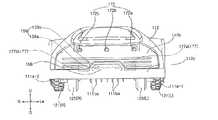
- FIG. 1is a perspective view of a mobile robot 100 according to an embodiment of the present invention.
- FIG. 2is an elevation view of the front of the mobile robot 100 of FIG. 1.
- FIG. 3is an elevation view of the right side of the mobile robot 100 of FIG. 1.
- FIG. 4is an elevation view of a lower side of the mobile robot 100 of FIG. 1.
- FIG. 5is a perspective view illustrating a docking device 200 for docking the mobile robot 100 of FIG. 1.
- FIG. 6is an elevational view of the docking device 200 of FIG.
- FIG. 7Ais a rear view of the reference wire according to an embodiment of the present invention.
- 7Bis a view of a reference wire according to an embodiment of the present invention viewed from one side.
- FIG. 8is a block diagram illustrating a control relationship of the mobile robot 100 of FIG. 1.
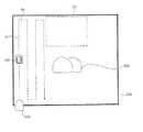
- FIG. 9is a view showing a mobile robot system according to an embodiment of the present invention.
- FIG. 10is a flowchart illustrating a driving control method according to an embodiment of a mobile robot.
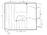
- 11A to 11Care state diagrams illustrating driving control according to the flowchart of FIG. 10.
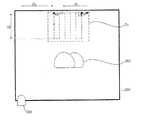
- FIG. 12is a state diagram illustrating driving control according to another embodiment of a mobile robot.
- each componentis exaggerated, omitted, or schematically illustrated for convenience and clarity of description.
- the size and area of each componentdoes not necessarily reflect the actual size or area.
- the lawn mower robot 100is described as an example, but is not necessarily limited thereto.
- the mobile robot 100includes a body 110 forming an appearance.
- the body 110forms an inner space.
- the mobile robot 100includes a driving unit 120 for moving the body 110 with respect to the running surface.
- the mobile robot 100includes a work unit 130 for performing a predetermined task.
- the body 110includes a frame 111 to which the driving motor module 123 to be described later is fixed.
- the blade motor 132 to be described lateris fixed to the frame 111.
- the frame 111supports a battery, which will be described later.
- Frame 111also provides a skeleton structure for supporting other components.
- the frame 111is supported by the assist wheel 125 and the drive wheel 121.
- the body 110includes side blocking portions 111a for blocking a user's finger from entering the blade 131 at both sides of the blade 131.
- the side blocking portion 111ais fixed to the frame 111.
- the side blocking portion 111ais disposed to protrude downward compared to the lower surface of the other part of the frame 111.
- the side blocking part 111ais disposed covering the upper part of the space between the driving wheel 121 and the auxiliary wheel 125.
- the pair of side blocking portions 111a-1 and 111a-2are disposed left and right with the blade 131 interposed therebetween.
- the side blocking portion 111ais disposed spaced apart from the blade 131 by a predetermined distance.
- the front surface 111af of the side blocking portion 111ais formed to be round.
- the front surface 111afforms a surface that is bent upward from the lower surface of the side blocking portion 111a toward the front.
- the body 110includes a front blocking part 111b for blocking a user's finger from entering the blade 131 in front of the blade 131.
- the front blocking portion 111bis fixed to the frame 111.
- the front blocking portion 111bis disposed covering a portion of the upper portion of the space between the pair of auxiliary wheels 125 (L) and 125 (R).
- the front blocking portion 111bincludes a protruding rib 111ba that projects downward compared to the lower surface of the other portion of the frame 111.
- the protruding ribs 111baextend in the front-rear direction.
- the upper end of the protruding rib 111bais fixed to the frame 111, and the lower end of the protruding rib 111ba forms a free end.
- the plurality of protruding ribs 111bamay be spaced apart in the left and right directions.
- the plurality of protruding ribs 111bamay be disposed in parallel to each other.
- a gapis formed between two adjacent protruding ribs 111ba.
- the front face of the protruding rib 111bais formed to be round.
- the front face of the protruding ribs 111baforms a surface that is bent upwards from the lower side of the protruding ribs 111ba toward the front.
- the front blocking portion 111bincludes an auxiliary rib 111bb that assists rigidity.
- An auxiliary rib 111bb for reinforcing the rigidity of the front blocking portion 111bis disposed between the upper ends of two adjacent protruding ribs 111ba.
- the auxiliary ribs 111bbmay protrude downward and extend in a lattice shape.
- the frame 111is provided with a caster (not shown) for rotatably supporting the auxiliary wheel 125.
- the casteris rotatably disposed with respect to the frame 111.
- the casteris rotatably provided about the vertical axis.
- the casteris disposed below the frame 111.
- a pair of castersis provided corresponding to the pair of auxiliary wheels 125.
- the body 110includes a case 112 covering the frame 111 from above.
- the case 112forms an upper side and a front / rear / left / right side of the mobile robot 100.
- the body 110may include a case connection part (not shown) that fixes the case 112 to the frame 111. It may be fixed to the case 112 on the top of the case connecting portion.
- the case connection partmay be arranged to be movable on the frame 111.
- the case connection partmay be disposed to be movable only in the vertical direction with respect to the frame 111.
- the case connection partmay be provided to be movable only within a predetermined range.
- the case connecting portionflows integrally with the case 112. As a result, the case 112 may flow with respect to the frame 111.
- Body 110includes bumper 112b disposed at the front.
- the bumper 112bmay absorb a shock when in contact with an external obstacle.
- a bumper groove formed in the front side of the bumper 112bmay be formed to be recessed to the rear side and formed to extend in the left and right directions.
- a plurality of bumper groovesmay be spaced apart in the vertical direction.
- the lower end of the protruding rib 111bais disposed at a lower position than the lower end of the auxiliary rib 111bb.
- the bumper 112bis formed by connecting the front surface and the left and right sides thereof to each other.
- the front and side surfaces of the bumper 112bare connected roundly.
- the body 110may include a bumper auxiliary part 112c disposed to surround the outer surface of the bumper 112b.
- Bumper auxiliary portion 112cis coupled to bumper 112b.
- the bumper auxiliary part 112csurrounds the lower part of the front face and the lower left and right sides of the bumper 112b.
- the bumper auxiliary part 112cmay cover the lower half of the front surface and the left and right sides of the bumper 112b.
- the front end face of the bumper auxiliary part 112cis disposed in front of the front end face of the bumper 112b.
- the bumper auxiliary portion 112cforms a surface protruding from the surface of the bumper 112b.
- the bumper auxiliary part 112cmay be formed of a material advantageous for shock absorption such as rubber.
- the bumper auxiliary part 112cmay be formed of a flexible material.
- the frame 111may be provided with a flow fixing part (not shown) to which the bumper 112b is fixed.
- the flow fixing partmay be disposed to protrude upward of the frame 111.
- the bumper 112bmay be fixed to the upper end of the flow fixing part.
- the bumper 112bmay be disposed to be movable within a predetermined range with respect to the frame 111.
- the bumper 112bmay be fixed to the flow fixing part and flow integrally with the flow fixing part.
- the flow fixing partmay be disposed in the frame 111 in a flowable manner.
- the flow fixing partmay be provided to be rotatable within a predetermined range with respect to the frame 111 about the virtual rotation axis. Accordingly, the bumper 112b may be rotatably provided integrally with the flow fixing part with respect to the frame 111.
- Body 110includes handle 113.
- the handle 113may be disposed at the rear side of the case 112.
- the body 110includes a battery inlet 114 for drawing out a battery.
- the battery input unit 114may be disposed on the lower surface of the frame 111.
- the battery input unit 114may be disposed at the rear side of the frame 111.
- the body 110includes a power switch 115 for turning on / off the power of the mobile robot 100.
- the power switch 115may be disposed on the lower surface of the frame 111.
- the body 110includes a blade protector 116 covering the lower side of the central portion of the blade 131.
- the blade protector 116is provided so that the blade of the centrifugal portion of the blade 131 is exposed but the center portion of the blade 131 is covered.
- the body 110includes a first opening and closing portion 117 that opens and closes a portion where the height adjusting portion 156 and the height display portion 157 are disposed.
- the first opening and closing part 117is hinged to the case 112 and is provided to enable the opening and closing operations.
- the first opening and closing part 117is disposed on the upper side surface of the case 112.
- the first opening / closing part 117is formed in a plate shape and covers the upper side of the height adjusting part 156 and the height display part 157 in the closed state.
- the body 110includes a second opening and closing portion 118 that opens and closes a portion where the display module 165 and the input unit 164 are disposed.
- the second opening and closing part 118is hinged to the case 112 and is provided to enable the opening and closing operations.
- the second opening and closing portion 118is disposed on the upper side of the case 112.
- the second opening and closing portion 118is disposed behind the first opening and closing portion 117.
- the second opening / closing part 118is formed in a plate shape to cover the display module 165 and the input unit 164 in the closed state.
- the openable angle of the second opening / closing portion 118is preset to be smaller than the openable angle of the first opening / closing portion 117. Through this, even in the open state of the second opening and closing portion 118, the user can easily open the first opening and closing portion 117, and allows the user to easily operate the height adjustment unit 156. In addition, even when the second opening / closing part 118 is opened, the user can visually check the contents of the height display part 157.
- the openable angle of the first opening / closing part 117may be provided to be about 80 to 90 degrees based on the closed state.
- the openable angle of the second opening / closing part 118may be provided to be about 45 to 60 degrees based on the closed state.
- the first opening / closing part 117is opened by the rear end being lifted upward from the front end, and the second opening / closing part 118 is opened by the rear end being lifted upward from the front end.
- the usercan open and close the first opening and closing portion 117 and the second opening and closing portion 118 in the rear of the lawn mowing robot 100, which is a safe area even when the mowing robot 100 moves forward.
- the opening operation of the first opening and closing portion 117 and the opening operation of the second opening and closing portion 118may be prevented from interfering with each other.
- the first opening and closing portion 117may be provided to be rotatable with respect to the case 112 about the rotation axis extending in the left and right directions from the front end of the first opening and closing portion 117.
- the second opening and closing portion 118may be provided to be rotatable with respect to the case 112 about the rotation axis extending in the left and right directions from the front end of the second opening and closing portion 118.
- the body 110includes a first motor housing 119a for accommodating the first drive motor 123 (L) and a second motor housing for accommodating the second drive motor 123 (R). 119b).
- the first motor housing 119amay be fixed to the left side of the frame 111
- the second motor housing 119bmay be fixed to the right side of the frame.
- the right end of the first motor housing 119ais fixed to the frame 111.
- the left end of the second motor housing 119bis fixed to the frame 111.
- the first motor housing 119ais formed in a cylindrical shape that forms a height from side to side as a whole.
- the second motor housing 119bis formed in a cylindrical shape that forms a height from side to side as a whole.
- the driving unit 120includes a driving wheel 121 that is rotated by the driving force of the driving motor module 123.
- the driving unit 120may include at least one pair of driving wheels 121 that are rotated by the driving force of the driving motor module 123.
- the drive wheel 121includes a first wheel 121 (L) and a second wheel 121 (R) which are provided on the left and right so as to be rotatable independently of each other.
- the first wheel 121 (L)is disposed at the left side
- the second wheel 121 (R)is disposed at the right side.
- the first wheel 121 (L) and the second wheel 121 (R)are spaced apart from side to side.
- the first wheel 121 (L) and the second wheel 121 (R)are disposed below the rear side of the body 110.
- the first wheel 121 (L) and the second wheel 121 (R)are each rotatably provided so that the body 110 can rotate and move forward with respect to the ground.
- the body 110may move forward with respect to the ground.
- the rotation speed of the first wheel 121 (L)is faster than the rotation speed of the second wheel 121 (R) or the rotation direction of the first wheel 121 (L) and the second wheel 121.
- the rotation directions of (R)are different from each other, the body 110 may rotate in relation to the ground.
- the first wheel 121 (L) and the second wheel 121 (R)may be larger than the auxiliary wheel 125.
- An axis of the first driving motor 123 (L)may be fixed to the center of the first wheel 121 (L), and a second driving motor 123 (R) to the center of the second wheel 121 (R). The axis of) may be fixed.
- the driving wheel 121includes a wheel outer circumferential portion 121b in contact with the ground.
- the wheel outer circumference 121bmay be a tire.
- the wheel outer circumferential portion 121bmay be provided with a plurality of protrusions for increasing friction with the ground.
- the driving wheel 121may include a wheel frame (not shown) which fixes the wheel outer periphery 121b and receives the power of the motor 123.
- the shaft of the motor 123is fixed to the center of the wheel frame, it can receive a rotational force.
- the wheel outer portion 121bis disposed to surround the circumference of the wheel frame.
- the drive wheel 121includes a wheel cover 121a that covers the outer surface of the wheel frame.
- the wheel cover 121ais disposed in a direction opposite to the direction in which the motor 123 is disposed based on the wheel frame.
- the wheel cover 121ais disposed at the center of the wheel outer circumferential portion 121b.
- the driving unit 120includes a driving motor module 123 for generating a driving force, and includes a driving motor module 123 for providing a driving force to the driving wheel 121.
- the driving motor module 123includes a first wheel. And a first driving motor 123 (L) for providing a driving force of 121 (L), and a second driving motor 123 (R) for providing a driving force of the second wheel 121 (R).
- the first driving motor 123 (L) and the second driving motor 123 (R)may be disposed to be spaced apart from side to side.
- the first driving motor 123 (L)may be arranged as the second driving motor 123 (L). R)) may be disposed on the left side.
- the first driving motor 123 (L) and the second driving motor 123 (R)may be disposed under the body 110.
- the first driving motor 123 (L) and the second driving motor 123 (R)may be disposed at the rear portion of the body 110.
- the first driving motor 123 (L)is disposed on the right side of the first wheel 121 (L), and the second driving motor 123 (R) is disposed on the left side of the second wheel 121 (R). Can be.
- the first driving motor 123 (L) and the second driving motor 123 (R)are fixed to the body 110.
- the first driving motor 123 (L)may be disposed inside the first motor housing 119a so that the motor shaft protrudes to the left side.
- the second driving motor 123 (R)may be disposed in the second motor housing 119b so that the motor shaft protrudes to the right.
- the first wheel 121 (L) and the second wheel 121 (R)are the rotation shafts of the first drive motor 123 (L) and the rotation shafts of the second drive motor 123 (R), respectively.
- partssuch as a shaft may be connected, or by a gear or a chain, such as a motor (123 (L), 123 (R)) ) May be implemented to be transmitted to the wheels (121a, 120b).
- the driving unit 120may include an auxiliary wheel 125 supporting the body 110 together with the driving wheel 121.
- the auxiliary wheel 125may be disposed in front of the blade 131.
- the auxiliary wheel 125is a wheel that does not receive the driving force by the motor, and serves to support the body 110 with respect to the ground.
- the caster supporting the rotation axis of the auxiliary wheel 125is coupled to the frame 111 so as to be rotatable about a vertical axis.
- the first auxiliary wheel 125 (L) disposed on the left side and the second auxiliary wheel 125 (R) disposed on the right sidemay be provided.
- the work unit 130is provided to perform a predetermined task.
- the working portion 130is disposed on the body 110.
- the work unit 130may be provided to perform a task such as cleaning or mowing.
- the work unit 130may be provided to perform an operation such as transporting an object or finding an object.
- the work unit 130may perform a security function for detecting an external intruder or a dangerous situation in the vicinity.
- the work unit 130is described as mowing the lawn, but the kind of work of the work unit 130 may be various examples, and need not be limited to the example of the present description.
- the work unit 130may include a blade 131 rotatably provided to mow the lawn.
- the work unit 130may include a blade motor 132 that provides a rotational force of the blade 131.
- the blade 131is disposed between the driving wheel 121 and the auxiliary wheel 125.
- the blade 131is disposed at the lower side of the body 110.
- the blade 131is provided to be exposed from the lower side of the body 110.
- the blade 131rotates about a rotation axis extending in the vertical direction to mow the lawn.
- the blade motor 132may be disposed in front of the first wheel 121 (L) and the second wheel 121 (R). The blade motor 132 is disposed below the central portion in the internal space of the body 110.
- the blade motor 132may be disposed at the rear side of the auxiliary wheel 125.
- the blade motor 132may be disposed below the body 110.
- the rotational force of the motor shaftis transmitted to the blade 131 using a structure such as a gear.
- the mobile robot 100includes a battery (not shown) for supplying power to the driving motor module 123.
- the batterysupplies power to the first driving motor 123 (L).
- the batterysupplies power to the second driving motor 123 (R).
- the batterymay supply power to the blade motor 132.
- the batterymay provide power to the controller 190, the azimuth sensor 176, and the output unit 165.
- the batterymay be disposed below the rear side in the internal space of the body 110.
- the mobile robot 100is provided to change the height of the blade 131 with respect to the ground, it is possible to change the mowing height of the grass.
- the mobile robot 100includes a height adjusting unit 156 for changing a height of the blade 131 by the user.
- the height adjusting unit 156may include a rotatable dial to change the height of the blade 131 by rotating the dial.
- the mobile robot 100includes a height display unit 157 that displays the level of the height of the blade 131.
- the height display unit 157may display the expected height value of the lawn after the mobile robot 100 mows to the current blade 131 height.
- the mobile robot 100includes a docking insertion unit 158 connected to the docking device 200 when the docking device 200 is docked.
- the docking inserting portion 158is provided to be recessed to insert the docking connection portion 210 of the docking device 200.
- the docking insert 158is disposed at the front of the body 110.
- the mobile robot 100may include a charging corresponding terminal 159 disposed at a position in contact with the charging terminal 211, which will be described later, while the docking insertion unit 158 is inserted into the docking connection unit 210.
- the charging corresponding terminal 159may include a pair of charging corresponding terminals 159a and 159b disposed at positions corresponding to the pair of charging terminals 211 (211a and 211b).
- the pair of charging corresponding terminals 159a and 159bmay be disposed left and right with the docking insertion portion 158 interposed therebetween.
- a terminal covermay be provided to cover the docking insertion unit 158 and the pair of charging terminals 211, 211a and 211b to be opened and closed.
- the terminal covermay cover the docking inserting portion 158 and the pair of charging terminals 211 (211a, 211b).
- a terminal covermay be opened to expose the docking insertion unit 158 and a pair of charging terminals 211a and 211b.
- the docking device 200includes a docking base 230 disposed on the bottom, and a docking support part 220 protruding upward from the front portion of the docking base 230.
- the docking base 230defines a plane parallel to the horizontal direction.
- the docking base 230has a plate shape in which the mobile robot 100 may be seated.
- the docking support 220extends in the docking base 230 in a direction crossing the horizontal direction.
- the docking connector 210When the mobile robot 100 is charged, the docking connector 210 is inserted into the docking insertion unit 158.
- the docking connection portion 210may protrude rearward from the docking support 220.
- the docking connection portion 210may have a thickness in the vertical direction smaller than the width in the left and right directions.
- the left and right width of the docking connection portion 210may be formed to be narrower toward the rear side.
- the docking connection 210is trapezoidal in its entirety.
- the docking connection portion 210is formed in a symmetrical shape.
- the rear portion of the docking connection portion 210forms a free end, and the front portion of the docking connection portion 210 is fixed to the docking support portion 220.
- the rear portion of the docking connection portion 210may be formed in a rounded shape.
- the docking device 200includes a charging terminal 211 for charging the mobile robot 100.
- the charging terminal 211 and the charging corresponding terminal 159 of the mobile robot 100are in contact with each other, so that power for charging may be supplied from the docking device 200 to the mobile robot 100.
- the charging terminal 211includes a contact surface facing the rear side, and the charging corresponding terminal 159 includes a contact corresponding surface facing the front side.
- the contact surface of the charging terminal 211 and the contact corresponding surface of the charging corresponding terminal 159contact each other, the power supply of the docking device 200 is connected to the mobile robot 100.
- the charging terminal 211may include a pair of charging terminals 211 (211a and 211b) forming a positive electrode and a negative electrode.
- the first charging terminals 211 and 211aare provided to contact the first charging corresponding terminal 159a, and the second charging terminals 211 and 211b are provided to contact the second charging corresponding terminal 159b.
- the pair of charging terminals 211, 211a and 211bmay be disposed with the docking connection portion 210 interposed therebetween.
- the pair of charging terminals 211, 211a and 211bmay be disposed at left and right sides of the docking connection portion 210.
- the docking base 230includes a wheel guard 232 on which the driving wheel 121 and the auxiliary wheel 125 of the mobile robot 100 are raised.
- the wheel guard 232includes a first wheel guard 232a for guiding the movement of the first auxiliary wheel 125 and a second wheel guard 232b for guiding the movement of the second auxiliary wheel 125.
- An upper convex center base 231is disposed between the first wheel guard 232a and the second wheel guard 232b.
- the docking base 230includes a slip prevention part 234 for preventing sliding of the first wheel 121 (L) and the second wheel 121 (R).
- the slip prevention part 234may include a plurality of protrusions protruding upward.
- the boundary wire 290 for setting the boundary of the travel area of the mobile robot 100may be implemented.
- the boundary wire 290may generate a predetermined boundary signal.
- the mobile robot 100may detect the boundary signal and recognize the boundary of the driving area set by the boundary wire 290.
- a predetermined electric currentmay flow along the boundary wire 290 to generate a magnetic field around the boundary wire 290.
- the generated magnetic fieldis a boundary signal.
- the magnetic field generated around the boundary wire 290may change with a predetermined change pattern.
- the mobile robot 100may recognize that it is close to the boundary wire 290 within a predetermined distance by using the boundary signal detection unit 177 that detects a magnetic field, and thereby, within the boundary set by the boundary wire 290. You can only drive in the driving area.
- the boundary wire 290may generate a magnetic field in a direction distinct from the reference wire 270.
- the boundary wire 290may be disposed substantially parallel to the horizontal plane.
- substantially parallelmay include parallel in an engineering sense including complete parallelism of mathematical meaning and a certain level of error.
- the docking device 200may serve to send a predetermined current to the boundary wire 290.
- the docking device 200may include a wire terminal 250 that is connected to the boundary wire 290. Both ends of the boundary wire 290 may be connected to the first wire terminal 250a and the second wire terminal 250b, respectively. Through the connection of the boundary wire 290 and the wire terminal 250, the power supply of the docking device 200 may supply a current to the boundary wire 290.
- the wire terminal 250may be disposed in front of the docking device 200. That is, the wire terminal 250 may be disposed on the side opposite to the direction in which the docking connection portion 210 protrudes.
- the wire terminal 250may be disposed on the docking support 220.
- the first wire terminal 250a and the second wire terminal 250bmay be spaced apart from left and right.
- the docking device 200may include a wire terminal opening and closing unit 240 to cover the wire terminal 250 to be opened and closed.
- the wire terminal opening and closing unit 240may be disposed at the front side F of the docking support unit 220.
- Wire terminal opening and closing unit 240is hinged to the docking support portion 220, it may be set in advance to open and close the operation through the rotation operation.
- the reference wire 270 for recognizing the position of the docking device 200 to the mobile robot 100may be implemented.
- the reference wire 270may generate a predetermined docking position signal.
- the mobile robot 100senses the docking position signal, recognizes the position of the docking device 200 by the reference wire 270, and when a return command or charging is required, the mobile robot 100 moves to the recognized docking device 200 position. You can return.
- Such a position of the docking device 200may be a reference point of driving of the mobile robot 100.
- the reference wire 270is formed of a conductive material through which electricity can flow.
- the reference wire 270may be connected to a power source of the docking device 200 which will be described later.
- a predetermined currentmay flow along the reference wire 270 to generate a magnetic field around the reference wire 270.
- the generated magnetic fieldis a docking position signal.
- An alternating current having a predetermined change patternflows in the reference wire 270 so that a magnetic field generated around the reference wire 270 may change with a predetermined change pattern.
- the mobile robot 100may recognize that it is close to the reference wire 270 within a predetermined distance by using the boundary signal detection unit 177 that detects a magnetic field, and through this, the docking device set by the reference wire 270. It may return to the position of 200.
- the reference wire 270may generate a magnetic field in a direction distinct from the boundary wire 290.
- the reference wire 270may extend in a direction crossing the horizontal direction.
- the reference wire 270may extend in the vertical direction perpendicular to the horizontal direction.
- the reference wire 270may be installed in the docking device 200.
- the reference wire 270may be disposed at various locations in the docking device 200.
- FIG. 7Ais a view of the reference wire 270 according to the first embodiment of the present invention from the rear
- FIG. 7Bis a view of the reference wire 270 according to the first embodiment of the present invention from one side.
- the reference wire 270may be disposed inside the docking support 220. Since the reference wire 270 has to generate a magnetic field signal in the horizontal direction, the reference wire 270 is disposed to extend in the vertical direction. If the reference wire 270 is disposed on the docking base 230, there is a disadvantage that the thickness of the docking base 230 is very thick.
- the reference wire 270may include a vertical portion 271 extending at least in a direction crossing the horizontal direction.
- the vertical portion 271may be disposed substantially parallel to the vertical direction UD.
- the direction of electricity input from the vertical portion 271 of the reference wire 270may proceed from the top to the bottom direction, or may proceed from the bottom to the top direction.
- a plurality of vertical portions 271may be disposed to generate more than a predetermined docking position signal in the entire peripheral area of the docking device 200.
- the vertical portion 271may include a first vertical portion 271a and a second vertical portion 271b spaced apart from the first vertical portion 271a.
- the vertical portion 271may include only one of the first vertical portion 271a and the second vertical portion 271b.
- the first vertical portion 271a and the second vertical portion 271bare spaced apart in the left and right directions.
- the first vertical portion 271amay be disposed adjacent to the right end of the docking support 220
- the second vertical portion 271bmay be disposed adjacent to the left end of the docking support 220.
- an area where a magnetic field is generated by the reference wire 270is maximized around the docking device 200. Will be expanded.
- the traveling directions of the currents of the first vertical portion 271a and the second vertical portion 271bmay be the same or different.
- the second vertical portion 271bmay flow from the lower portion to the upper direction.
- first vertical portion 271a and the second vertical portion 271bmay be provided.
- the first vertical portion 271a and the second vertical portion 271bmay be a collection of multiple wires, and the first vertical portion 271a and the second vertical portion 271b may have a constant arrangement.
- a single number of the first vertical portion 271a and the second vertical portion 271bmay be disposed.
- the plurality of first vertical portions 271aare arranged in rows along a line extending in the front-back direction
- the plurality of second vertical portions 271bare arranged in rows along a line extending in the front-back direction. Can be.
- the plurality of first vertical portions 271a and the second vertical portions 271bare disposed at both ends in the left and right directions of the docking support 220 and arranged in rows in the front-rear direction, the plurality of first vertical portions 271a ) And the charging terminal 211 and the docking connection portion 210 may be disposed between the second vertical portion 271b.
- the configurations of the charging terminal 211 and the docking connection portion 210are not changed. There is an advantage in that the reference wire 270 can be placed.
- the plurality of first vertical portions 271a and the second vertical portions 271bmay be electrically connected to each other, or may be supplied with electricity from a separate power source.
- the docking device 200may serve to send a predetermined current to the reference wire 270.
- the docking device 200may include a wire terminal 250 connected to the reference wire 270. Both ends of the reference wire 270 may be connected to the first wire terminal 250a and the second wire terminal 250b, respectively. Through the connection of the reference wire 270 and the wire terminal 250, the power supply of the docking device 200 may supply a current to the reference wire 270.
- both ends of the plurality of first vertical portions 271aare connected to the first wire terminal 250a and the second wire terminal 250b, respectively, and both ends of the plurality of second vertical portions 271b are respectively the first ends. It may be connected to the wire terminal 250a and the second wire terminal 250b.
- the reference wire 270may further include a horizontal portion (not shown).
- the reference wire 270may have a structure in which the first vertical portion 271a and the second vertical portion 271b are connected to each other to receive power from one power source.
- FIG. 8is a block diagram illustrating a control relationship of the mobile robot 100 of FIG. 1.
- the mobile robot 100may include an input unit 164 that may input various instructions of a user.
- the input unit 164may include a button, a dial, a touch type display, and the like.
- the input unit 164may include a microphone (not shown) for speech recognition.
- a plurality of buttonsare arranged on the upper side of the case 112.
- the mobile robot 100may include an output unit 165 for outputting various types of information to the user.
- the output unit 165may include a display module for outputting visual information.
- the output unit 165may include a speaker (not shown) that outputs auditory information.
- the display module 165outputs an image in the upward direction.
- the display module 165is disposed above the case 112.
- the display module 165may include a thin film transistor liquid-crystal display (LCD) panel.
- the display module 165may be implemented using various display panels, such as a plasma display panel or an organic light emitting diode display panel.
- the mobile robot 100includes a storage unit 166 that stores various kinds of information.
- the storage unit 166records various kinds of information necessary for the control of the mobile robot 100 and may include a volatile or nonvolatile recording medium.
- the storage unit 166may store information input from the input unit 164 or received by the communication unit 167.
- the storage unit 166may store a program for controlling the mobile robot 100.
- the mobile robot 100may include a communication unit 167 for communicating with an external device (such as a terminal), a server, a router, and the like.
- the communication unit 167may be implemented to wirelessly communicate with a wireless communication technology such as IEEE 802.11 WLAN, IEEE 802.15 WPAN, UWB, Wi-Fi, Zigbee, Z-wave, Blue-Tooth and the like.
- the communication unitmay vary depending on what the communication method of the other device or server to communicate with.
- the mobile robot 100includes a sensing unit 170 that detects information related to a state of the mobile robot 100 or an environment outside the mobile robot 100.
- the sensing unit 170may include a remote signal detector 171, an obstacle detector 172, a rain detector 173, a case flow sensor 174, a bumper sensor 175, an azimuth sensor 176, and a boundary signal.
- the detector 177, the GPS detector 178, and the cliff detector 179may be included.
- the remote signal detector 171receives an external remote signal.
- the remote signal detector 171may receive the remote signal.
- the remote signalmay be an infrared signal.
- the signal received by the remote signal detector 171may be processed by the controller 190.
- a plurality of remote signal detection unit 171may be provided.
- the plurality of remote signal detectors 171may include a first remote signal detector 171a disposed at the front of the body 110 and a second remote signal detector 171b disposed at the rear of the body 110. ) May be included.
- the first remote signal detector 171areceives a remote signal transmitted from the front side.
- the second remote signal detector 171breceives a remote signal transmitted from the rear side.
- the obstacle detecting unit 172detects an obstacle around the mobile robot 100.
- the obstacle detecting unit 172may detect an obstacle in front of the vehicle.
- a plurality of obstacle detection units 172a, 172b, and 172cmay be provided.
- the obstacle detecting unit 172is disposed on the front surface of the body 110.
- the obstacle detecting unit 172is disposed above the frame 111.
- the obstacle detecting unit 172may include an infrared sensor, an ultrasonic sensor, an RF sensor, a geomagnetic sensor, a position sensitive device (PSD) sensor, and the like.
- PSDposition sensitive device
- the rain detector 173detects rain when it rains in an environment in which the mobile robot 100 is placed.
- the rain detector 173may be disposed in the case 112.
- the case flow sensor 174senses the flow of the case connection. When the case 112 is lifted upward with respect to the frame 111, the case connection part flows upward, and the case flow sensor 174 detects the lift of the case 112. When the case flow sensor 174 detects the lifting of the case 112, the controller 190 may control to stop the operation of the blade 131. For example, the case flow sensor 174 can detect this when a user raises the case 112 or when a significant obstacle lowers the case 112.
- the bumper sensor 175may detect rotation of the flow fixing part.
- a magnetmay be disposed on one side of the lower part of the flow fixing part, and a sensor for detecting a change in the magnetic field of the magnet may be disposed on the frame 111.
- the sensorsenses a change in the magnetic field of the magnet, such that the bumper sensor 175 detecting the rotation of the flow fixing part may be implemented.
- the flow fixing partrotates integrally with bumper 112b.
- the bumper sensor 175detects the rotation of the flow fixing part, thereby detecting the impact of the bumper 112b.
- the azimuth sensor (AHRS) 176may have a gyro sensing function.
- the azimuth sensor 176may further include an acceleration sensing function.
- the azimuth sensor 176may further include a magnetic field sensing function.
- the azimuth sensor 176may include a gyro sensing module 176a that performs gyro sensing.
- the gyro sensing module 176amay detect a horizontal rotation speed of the body 110.
- the gyro sensing module 176amay detect a tilting speed of the horizontal plane of the body 110.
- the gyro sensing module 176amay have a gyro sensing function for three axes of a spatial coordinate system orthogonal to each other.
- the information collected by the gyro sensing module 176amay be roll, pitch, and yaw information.
- the processing modulecan calculate the direction angle of the mobile robot 100 by integrating a rolling, pitch, and yaw angular velocity.
- the azimuth sensor 176may include an acceleration sensing module 176b that performs acceleration sensing.
- the acceleration sensing module 176bmay have an acceleration sensing function with respect to three axes of a spatial coordinate system orthogonal to each other.
- the predetermined processing modulecan calculate the speed by integrating the acceleration, and can calculate the moving distance by integrating the speed.
- the azimuth sensor 176may include a magnetic field sensing module 176c that performs magnetic field sensing.
- the magnetic field sensing module 176cmay have a magnetic field sensing function with respect to three axes of a spatial coordinate system orthogonal to each other.
- the magnetic field sensing module 176cmay detect a magnetic field of the earth.
- the boundary signal detector 177detects a boundary signal of the boundary wire 290 and / or a docking position signal of the reference wire 270.
- the boundary signal detector 177may be disposed at the front of the body 110. In this way, the boundary of the travel area can be detected early while moving forward, which is the main travel direction of the mobile robot 100.
- the boundary signal detector 177may be disposed in the inner space of the bumper 112b.
- the boundary signal detection unit 177may include a first boundary signal detection unit 177a and a second boundary signal detection unit 177b spaced apart from left and right.
- the first boundary signal detector 177a and the second boundary signal detector 177bmay be disposed in front of the body 110.
- the boundary signal detector 177includes a magnetic field sensor.
- the boundary signal detector 177may be implemented using a coil to detect a change in the magnetic field.
- the boundary signal detector 177may detect a magnetic field in at least the horizontal direction.
- the boundary signal detector 177may detect magnetic fields of three axes orthogonal to each other in space.
- the first boundary signal detector 177amay detect a magnetic field signal in a direction orthogonal to the second boundary signal detector 177b.
- the first boundary signal detector 177a and the second boundary signal detector 177bdetect magnetic field signals in a direction orthogonal to each other, and combine the detected magnetic field signal values with respect to three axes perpendicular to each other in space. Magnetic field can be detected.
- the boundary signal detecting unit 177determines the direction of the magnetic field using a sum vector value for the three axes, and when the direction of the magnetic field is close to the horizontal direction.
- the docking position signalmay be recognized and if it is close to the vertical direction, it may be recognized as a boundary signal.
- the boundary signal detecting unit 177distinguishes the boundary signals of the adjacent boundary signals and the plurality of driving regions by the difference in intensity of the magnetic field, and determines the adjacent boundary signals and the docking position signal. The difference in the direction of the magnetic field can be distinguished.
- the boundary signal detecting unit 177may distinguish the boundary signals of the adjacent boundary signals and the plurality of driving regions with a difference in magnetic field distribution.
- the boundary signal detecting unit 177may recognize that the magnetic field has a plurality of peaks within a predetermined distance on the plane coordinates and recognize the adjacent boundary signal.
- the GPS detector 178may be provided to detect a Global Positioning System (GPS) signal.
- GPSGlobal Positioning System
- the GPS detector 178may be implemented using a PCB.
- the cliff detecting unit 179detects the presence of a cliff on the running surface.
- the cliff detector 179may be disposed at the front of the body 110 to detect the presence of a cliff in front of the mobile robot 100.
- the sensing unit 170may include an opening and closing detection unit (not shown) that detects whether at least one of the first opening and closing unit 117 and the second opening and closing unit 118 is opened or closed.
- the open / close detection unitmay be disposed in the case 112.
- the mobile robot 100includes a controller 190 for controlling autonomous driving.
- the controller 190may process a signal from the sensing unit 170.
- the controller 190may process a signal of the input unit 164.
- the controller 190may control driving of the first driving motor 123 (L) and the second driving motor 123 (R).
- the controller 190may control the driving of the blade motor 132.
- the controller 190may control the output of the output unit 165.
- the controller 190includes a main board (not shown) disposed in the internal space of the body 110.
- Main boardmeans PCB.
- the controller 190may control autonomous driving of the mobile robot 100.
- the controller 190may control the driving of the driving unit 120 based on the signal received from the input unit 164.
- the controller 190may control the driving of the driving unit 120 based on the signal received from the sensing unit 170.
- controller 190may process a signal of the boundary signal detector 177.
- the controller 190may determine the current position by analyzing the boundary signal through the boundary signal detection unit 177 and control the driving of the driving unit 120 according to the driving pattern.
- the controller 190may control the driving unit 120 according to the driving pattern of the zigzag mode.
- FIG. 9is a view showing a mobile robot 100 system according to an embodiment of the present invention.
- a boundary wire 290 defining one travel area Zdis disposed, and the mobile robot 100 traveling inside the travel area Zd. It may include.
- the mobile robot 100 system of the present inventionmay further include a docking device 200 to which the mobile robot 100 is docked and charged.
- one driving region Zdis illustrated as an example in FIG. 9, the present disclosure is not limited thereto, and a plurality of driving regions Zd may be formed.
- an obstacle 300 in one driving area Zdwhich is an area that is hindered by pattern driving by a facility or an arbitrary structure.
- An area in which the obstacle 300 is locatedis defined as an obstacle zone, and the obstacle 300 is not partitioned by a separate boundary wire.
- the obstacle 300may be detected by the obstacle detector 172, and the obstacle detector 172 may detect the obstacle 300 in front of the obstacle 300 and transmit a detection signal to the controller 190.
- the controller 190may determine whether the obstacle 300 exists by analyzing the detection signals from various sensors from the plurality of obstacle detecting units 172a, 172b, and 172c.
- the obstacle 300may be formed in a polygon as shown in FIG. 9, but may be formed in an approximately circular shape.
- the controller 190may perform a pattern driving mode in which one driving region Zd runs in a predetermined pattern.
- a predetermined pattern driving mode for moving the body 110 along predetermined pattern paths Sr and Svis preset.
- the pattern driving modeincludes at least a predetermined algorithm for driving the driving unit 120.
- the pattern driving modemay include an algorithm for driving the driving unit 120 according to a sensing signal of the sensing unit 170.
- the mobile robot 100may travel in a zigzag mode based on a position where the docking device 200 is disposed in the travel area Zd. That is, the mobile robot 100 travels along the long axis Sr from the start point to the rear side R. As shown in FIG. In this case, when the edge signal is determined by receiving the boundary signal from the boundary wire 290, the edge region is rotated to the right side in the direction in which the remaining region exists, and then travels along the short axis Sv.
- the rotating anglemay be an angle between 120 degrees and 60 degrees, and preferably about 90 degrees.
- traveling along the long axis (Sr)is moving forward (F) as described above, alternately driving the long axis (Sr) and the short axis (Sv) in one running area (Zd) driving in a zigzag mode, mowing the lawn Perform. Therefore, a plurality of long axes Sr and a plurality of short axes Sv for traveling in one travel area Zd may be designed in a target pattern, and the plurality of long axes Sr may be parallel to each other.
- the lengths of the long axis Sr and the short axis Svare set, and the mobile robot 100 moves in the zigzag mode along the set long axis Sr and the short axis Sv.
- the lawnmower robotcan move according to the pattern driving mode while rotating the blade 131 to uniformly mow the grass in the running area Zd.
- the lawn mowingcan be progressed to a length of about 1 to 2 mm for each driving. Therefore, since the lawn is mowed a plurality of times, it is possible to reduce the discomfort of the user due to the visible difference between the driving area Zd and the non-traveling area.
- the controller 190determines whether the obstacle 300 exists, and accordingly, runs the pattern in accordance with the obstacle 300.
- the controller 190when driving in the zigzag mode in the direction of the pattern and facing the obstacle 300, the controller 190 receives a detection signal from the obstacle 300 sensing unit 172 and accordingly the obstacle 300 If it is determined that the length of the long axis (Sr) of the pattern path is reset.
- the distance to the obstacle 300is set as the long axis Sr, and the pattern is continuously driven in the direction of the pattern according to the set new long axis Sr and the previous short axis Sv.
- FIGS. 11A to 11Care state diagrams illustrating driving control according to the first embodiment.
- the controller 190sets the length of the long axis Sr of the pattern to the first length d1 in the first direction Dd, which is the pattern travel direction of the driving area Zd, to proceed with driving. (S100).
- the length of the short axis Svmay be fixed to a specific length according to the width of the mobile robot 100, a distance required for rotation, and the like, but may be changed according to a setting.
- the mobile robot 100may encounter an obstacle 300 while driving the pattern under the control of the controller 190.
- the controller 190receives a detection signal from the obstacle detecting unit 172 generated by the obstacle 300 and determines whether the non-driving area Zu is generated by the obstacle 300 (S110).
- the obstacle detecting unitis operated at a point no which travels by the second length d2 shorter than the first length d1 while traveling by the first length d1 along the long axis Sr.
- the controller 190determines that the obstacle 300 exists, and accordingly changes the long axis Sr of the pattern path.
- the controller 190may enter a preparation mode for generating the non-traveling region Zu by the obstacle 300.
- the controller 190sets the length of the long axis Sr of the pattern path to the second length d2 to continue the pattern driving along the first direction Dd, which is the pattern advancing direction (S120).
- the controller 190periodically determines whether the obstacle area is finished (S130).
- the determination of the end of the obstacle regionmay be determined depending on whether the length of the long axis Sr is increased again.
- the length of the long axis Sris longer than the second length d2, it may be determined that the obstacle 300 region is finished.
- the patternruns along the long axis Sr of the set second length d2.
- the boundary signalis received. It moves along the long axis Sr until it reaches the 1st end point n1 of the long axis Sr.
- the controller 190defines the length of the long axis Sr at the end point n1 of the long axis Sr as the third length d3, the third length d3 is greater than the second length d2. At the same time, it is determined that the obstacle zone is over.
- the controller 190may calculate the distance in the short axis direction in which the long axis Sr travels at the second length d2 as the width Wa of the obstacle 300.
- the controller 190proceeds with the pattern driving of the non-driving area Zu generated by the obstacle 300, that is, the rear area of the obstacle 300.
- the first end point n1 of the long axis Sris moved along the short axis Sv in the second direction Dr, which is the reverse direction of the pattern travel direction, to reach the second end point n2.
- the distance W2 moving along the short axis Sv in the second direction Dris the length of one short axis Sv, that is, the length of the short axis direction corresponding to 1/2 cycle of the pattern path and the calculated obstacle ( It may be equal to or greater than the sum of the width Wa of 300.
- the controller 190reaches the end point n3 of the obstacle 300 by pattern driving along the long axis Sr in the first direction Dd toward the obstacle 300 from the second end point n2 ( S150).
- the pattern driving of the non-traveling region Zumay be performed by newly setting the long axis Sr to the fourth length d4, and the fourth length d4 corresponds to the length of the non-traveling region Zu. It may be calculated by the detection signal by the obstacle detection unit 172.
- the controller 190determines that the obstacle area is over, and again the long axis Sr along the pattern advancing direction in the first direction Dd.
- the pattern drivingis started by setting the length to the third length d3 (S160).
- the vehicletravels a distance greater than the width of the obstacle 300 in the reverse direction, and the non-traveling area Zu ) Can proceed with the pattern driving.
- the controller 190may record the driving record of the pattern driving mode in the storage unit 166 and use it as raw data when the next mobile robot 100 travels.
- controller 190may control the driving according to the shape of the obstacle 300 as shown in FIG. 12.
- FIG. 12is a state diagram illustrating driving control according to another embodiment of a mobile robot.
- an obstacle 300is formed in the travel area Zd.
- the obstacle 300may have a polygonal shape, for example, a rectangular shape, not a circular shape.
- the obstacle 300may be a very small size.
- the controller 190may ignore the existence of the obstacle 300.
- the obstacle 300 of FIG. 12satisfies that the width of the obstacle 300 is smaller than the length in the short axis direction of one cycle of the zigzag pattern and larger than the length in the short axis direction of the 1/2 cycle.
- the reverse travelingmay be performed in the second direction Dr along the short axis by the length in the short axis direction of one cycle.
- the pattern drivingis performed for one cycle in the first direction Dd in the non-traveling region Zu, and then, the long axis Sr is further extended to the third length d3. ), You can proceed with pattern driving.
- the controller 190may record the driving record of the pattern driving mode in the storage unit 166 and use it as raw data when the next mobile robot 100 travels.
- the mobile robot 100detects the existence of the non-driving area by the obstacle 300 according to the size of the obstacle 300, and continuously runs the non-traveling area so that the grass uniform for the entire driving area. Cutting can proceed.
- sensing unit 190control unit
Landscapes
- Engineering & Computer Science (AREA)
- Physics & Mathematics (AREA)
- Radar, Positioning & Navigation (AREA)
- Mechanical Engineering (AREA)
- Remote Sensing (AREA)
- Automation & Control Theory (AREA)
- General Physics & Mathematics (AREA)
- Aviation & Aerospace Engineering (AREA)
- Robotics (AREA)
- Life Sciences & Earth Sciences (AREA)
- Environmental Sciences (AREA)
- Power Engineering (AREA)
- Electromagnetism (AREA)
- Transportation (AREA)
- Business, Economics & Management (AREA)
- Health & Medical Sciences (AREA)
- Artificial Intelligence (AREA)
- Evolutionary Computation (AREA)
- Game Theory and Decision Science (AREA)
- Medical Informatics (AREA)
- Harvester Elements (AREA)
- Control Of Position, Course, Altitude, Or Attitude Of Moving Bodies (AREA)
Abstract
Description
Translated fromKorean본 발명은 이동 로봇의 패턴 주행 시에 주행 영역 내에 장애물에 의해 발생하는 미주행 영역의 주행을 진행하는 이동로봇 및 이동로봇 시스템에 관한 것이다.The present invention relates to a mobile robot and a mobile robot system for driving a non-driving area generated by an obstacle in a driving area when driving a pattern of a mobile robot.
로봇은 산업용으로 개발되어 공장 자동화의 일 부분을 담당하여 왔다. 최근에는 로봇을 응용한 분야가 더욱 확대되어, 의료용 로봇, 우주 항공 로봇 등이 개발되고, 일반 가정에서 사용할 수 있는 가정용 로봇도 만들어지고 있다. 이러한 로봇 중에서 자력으로 주행이 가능한 것을 이동 로봇이라고 한다. 가정의 야외 환경에서 사용되는 이동 로봇의 대표적인 예는 잔디 깎기 로봇이다.Robots have been developed for industrial use and have been a part of factory automation. Recently, the application of robots has been further expanded, medical robots, aerospace robots, and the like have been developed, and home robots that can be used in general homes have also been made. Among these robots, a moving robot capable of traveling by magnetic force is called a mobile robot. A representative example of a mobile robot used in a home outdoor environment is a mowing robot.
실내를 자율 주행하는 이동 로봇의 경우 벽이나 가구 등에 의해 이동 가능 영역이 제한되나, 실외를 자율 주행하는 이동 로봇의 경우 이동 가능한 영역을 사전에 설정해야 할 필요성이 있다. 또한, 상기 잔디 깎기 로봇이 잔디가 심어진 영역을 주행하도록 이동 가능한 영역을 제한할 필요성이 있다.In the case of a mobile robot that autonomously runs indoors, the movable area is limited by walls or furniture, but in the case of a mobile robot that runs autonomously, it is necessary to set a movable area in advance. In addition, there is a need to limit the movable area so that the lawn mower robot travels in the area where the lawn mower is planted.
종래 기술(한국공개특허공보 제2015-0125508호)에서는, 잔디 깎기 로봇이 이동할 영역을 설정하기 와이어를 매설하고, 잔디 깎기 로봇은 와이어에 의해 흐르는 전류에 의해 형성되는 자기장을 센싱하여 와이어에 의해 설정된 영역 내에서 이동할 수 있다.In the prior art (Korean Patent Publication No. 2015-0125508), a wire is embedded to set an area to move the mowing robot, and the mowing robot senses a magnetic field formed by a current flowing through the wire and is set by the wire. You can move within the area.
또한, 종래 기술에 따르면, 와이어의 일 점을 출발점으로하여 패턴 주행을 실행하는 주행 방법이 개시되어 있다. 한 영역에 대하여는 복수회에 걸쳐 패턴 주행을 진행하고 있으며, 그에 따라 순차적으로 잔디 깎기가 진행된다.Moreover, according to the prior art, a traveling method is disclosed in which a pattern travel is executed by using one point of a wire as a starting point. Pattern driving is performed a plurality of times in one area, and accordingly, lawn mowing proceeds sequentially.
한편, 경계 와이어에 의해 구역이 정의된 주행 영역은 내부에 적어도 하나의 장애물 배치되어 있을 수 있다.On the other hand, at least one obstacle may be disposed in the traveling area in which the zone is defined by the boundary wire.
장애물은 잔디 깎기가 진행되는 주행 영역 내에 형성되어 있는 설치물 또는 임의적으로 놓여진 물품 등으로서 경계 와이어로 구획되어지지 않은 부분에 해당한다.The obstacle corresponds to a portion formed in the traveling area where the mowing proceeds, an article placed arbitrarily, or the like that is not partitioned by the boundary wire.
따라서, 경계 와이어에 의해 구획된 하나의 주행 영역 내에 주행할 수 없는 영역이 형성되어 있다.Therefore, the area | region which cannot run in one running area partitioned by the boundary wire is formed.
이동 로봇은 각 경계 와이어로부터의 신호에 따라 경계를 확인하면서 패턴 주행을 진행하므로, 패턴 주행 시에 장애물에 맞닥뜨리면, 이에 의해 장축 또는 단축의 길이를 변경하면서 장애물을 제외한 주행 영역의 잔디 깎기를 진행한다.Since the mobile robot proceeds with pattern driving while checking the boundary according to the signal from each boundary wire, if it encounters an obstacle during pattern driving, it mows the running area excluding the obstacle while changing the length of the long or short axis. do.
이와 관련하여, 종래 기술(미국특허공보 US7155309)에 따르면, 와이어 등의 마커에 의해 주행 영역 또는 장애물 등의 영역에 대한 경계를 확인하고, 그에 따라 패턴 주행을 진행하는 기술이 개시되어 있다.In this regard, according to the prior art (US Patent Publication No. US7155309), there is disclosed a technique of checking a boundary of a running area or an area such as an obstacle by a marker such as a wire, and accordingly driving a pattern.
그러나, 종래 기술(미국특허공보 US7155309)에는 이와 같은 패턴 주행에서 현재 로봇의 위치가 스캔한 주행 영역 내의 어느 위치에 해당하는지 연속적으로 위치 정보를 학인하기 위하여 네비게이션 시스템 및 센서 시스템이 모두 필수적으로 구비되어야 한다. 그러나, 로봇 내에 네비게이션 시스템이 구비되지 않은 경우에는 로봇이 현재 주행하고 있는 위치에 대하여 정보를 알 수 없고, 네비게이션 시스템이 구비되어 있다 하더라도 협소한 공간 내에서는 GPS 등으로부터 수신되는 절대 위치 정보의 오차가 매우 큰 영향을 미치게 된다.However, in the prior art (US Patent Publication No. US7155309), both a navigation system and a sensor system must be provided in order to continuously check the position information of the current robot position corresponding to the position in the scanned driving region in this pattern driving. do. However, if the robot is not equipped with a navigation system, information about the position at which the robot is currently traveling cannot be known, and even if a navigation system is provided, an error of absolute position information received from GPS or the like in a narrow space may be lost. It will have a big impact.
또한, 패턴 주행을 실행할 때, 장애물에 의해 패턴 주행의 장축 또는 단축의 길이가 가변되면 장애물 후면에 미주행 영역이 발생할 수 있다.In addition, when the pattern driving is executed, if the length of the long axis or the short axis of the pattern running is changed by the obstacle, the untraveling region may occur behind the obstacle.
특히, 네비게이션 시스템이 없는 경우에 이동 로봇은 장애물에 따라 패턴 주행이 완료된 것으로 판단하게 되므로 주행 영역 전체에 대하여 주행이 완료되더라도 미주행 영역에 대한 존재를 인지하지 못한다.In particular, when there is no navigation system, the mobile robot determines that the pattern driving is completed according to the obstacle, and thus, even if the driving is completed for the entire driving region, the mobile robot does not recognize the existence of the non-driving region.
[선행기술문헌][Preceding technical literature]
[특허문헌][Patent Documents]
한국공개특허공보 제2015-0125508호 (공개일 : 2015년 11월 9일)Korean Laid-Open Patent Publication No. 2015-0125508 (published: November 9, 2015)
미국특허공보 US7155309 (공개일 : 2005년 5월 26일)United States Patent Publication US7155309 (published: May 26, 2005)
본 발명의 제1 과제는 패턴 주행을 진행할 때, 주행 영역 내에 장애물이 존재하는지 판단하고, 장애물이 존재하는 경우, 이에 따라 패턴 주행의 길이를 가변하여 연속 주행을 진행하는데 있다.The first object of the present invention is to determine whether an obstacle exists in the travel area when the pattern travel is performed, and if the obstacle exists, vary the length of the pattern travel according to the continuous travel.
본 발명의 제2 과제는 현재 위치에 대한 절대 위치 정보 없이 장애물에 의해 발생하는 미주행 영역이 발생하는지 여부를 판단하여 미주행 영역의 주행을 진행하는데 있다.A second object of the present invention is to determine whether or not a non-traveling region generated by an obstacle occurs without absolute position information on a current position to drive the non-traveling region.
본 발명의 제3 과제는 주행 영역의 형상에 따라 미주행 영역이 있는지 판단함으로써 하나의 주행 영역에 패턴 주행으로 미주행 영역 없이 주행을 진행하여 업무 완성도를 향상시킬 수 있다.According to the third object of the present invention, by determining whether there is a non-traveling area according to the shape of the travel area, driving can be performed without a non-traveling area by pattern driving in one travel area, thereby improving work completion.
본 발명의 제4 과제는 장애물의 크기에 따라 미주행 영역의 패턴 주행을 진행함으로써 잔디가 깎기지 않는 영역이 최소화되도록 주행을 제어할 수 있다.According to a fourth aspect of the present invention, the driving may be controlled to minimize the area where the grass is not mowed by driving the pattern of the non-traveling area according to the size of the obstacle.
본 발명은 외관을 형성하는 바디; 상기 바디를 이동시키는 주행부; 주행 영역의 경계 영역에서 발생하는 경계 신호를 감지하는 경계 신호 감지부; 및 상기 주행부가 상기 주행 영역을 패턴 주행하도록 제어하고, 상기 주행 영역 내에 장애물이 존재할 때, 상기 장애물에 의한 미주행 영역을 탐색하여 상기 미주행 영역의 주행을 연속적으로 진행하도록 제어하는 제어부를 포함하는 이동 로봇을 제공한다.The present invention provides a body forming an appearance; A driving unit for moving the body; A boundary signal detector for detecting a boundary signal generated in the boundary region of the driving area; And a controller configured to control the driving unit to pattern-drive the driving region, and to control the driving of the non-driving region continuously by searching for the non-driving region caused by the obstacle when an obstacle exists in the driving region. Provide a mobile robot.
상기 제어부는 장축과 단축을 번갈아 주행하는 지그재그 모드의 패턴 주행을 수행하도록 상기 주행부를 제어할 수 있다.The controller may control the driving unit to perform pattern driving in a zigzag mode in which the long axis and the short axis travel alternately.
상기 제어부는, 상기 장애물의 존재를 감지하는 장애물 감지부로부터 감지 신호를 수신하여 상기 장애물의 존재를 판단할 수 있다.The controller may determine the existence of the obstacle by receiving a detection signal from the obstacle detecting unit detecting the presence of the obstacle.
상기 제어부는, 상기 장애물에 의해 상기 장축의 길이가 감소한 경우, 상기 장애물이 끝날 때까지 감소된 상기 장축의 길이에 따라 패턴 주행을 진행할 수 있다.When the length of the long axis is reduced by the obstacle, the controller may drive the pattern along the length of the long axis reduced until the obstacle ends.
상기 제어부는, 상기 장애물이 끝나면 상기 미주행 영역으로 이동하여 상기 미주행 영역에 대한 패턴 주행을 진행할 수 있다.When the obstacle is over, the controller may move to the non-traveling region and proceed with pattern driving for the non-traveling region.
상기 제어부는, 상기 장애물이 끝나면 장축의 끝점에서 상기 패턴 진행 방향의 역방향으로 상기 단축을 따라 소정 거리만큼 이동하여 상기 미주행 영역의 끝점에 도달할 수 있다.When the obstacle is over, the controller may move from the end point of the long axis to the end point of the non-traveling region by moving a predetermined distance along the short axis in the reverse direction of the pattern travel direction.
상기 제어부는, 상기 미주행 영역의 끝점으로부터 상기 패턴 진행 방향으로 상기 미주행 영역 내에서 패턴 주행을 수행할 수 있다.The controller may perform pattern driving in the non-traveling region in the pattern travel direction from an end point of the non-traveling region.
상기 제어부는, 상기 역방향으로 이동하는 소정 거리는 상기 장애물의 폭과 상기 단축의 길이의 합과 같거나 클 수 있다.The controller may be a predetermined distance moving in the reverse direction is equal to or greater than the sum of the width of the obstacle and the length of the short axis.
상기 제어부는 상기 미주행 영역에 대한 패턴 주행이 완료되면, 상기 주행 영역의 잔여 영역에 대한 패턴 주행을 연속적으로 진행할 수 있다.When the pattern driving for the non-traveling region is completed, the controller may continuously proceed with the pattern driving for the remaining region of the driving region.
상기 제어부는 상기 장애물의 폭이 상기 단축의 길이보다 작은 경우, 상기 장애물이 없는 것으로 판단할 수 있다.The controller may determine that the obstacle is absent when the width of the obstacle is smaller than the length of the short axis.
상기 제어부는 상기 장축이 제1 길이에서 제2 길이로 감소되는 때 상기 장애물의 존재를 감지할 수 있다.The controller may detect the presence of the obstacle when the long axis is reduced from the first length to the second length.
한편, 본 발명은 장애물을 포함할 수 있는 주행 영역을 정의하는 경계 와이어; 및 외관을 형성하는 바디, 상기 바디를 이동시키는 주행부, 상기 경계 와이어에서 발생하는 경계 신호를 감지하는 경계 신호 감지부, 및 상기 주행부가 상기 주행 영역을 패턴 주행하도록 제어하고, 상기 주행 영역 내에 장애물이 존재할 때, 상기 장애물에 의한 미주행 영역을 탐색하여 상기 미주행 영역의 주행을 연속적으로 진행하도록 제어하는 제어부를 포함하는 이동 로봇을 포함하는 이동 로봇 시스템을 제공한다.On the other hand, the present invention includes a boundary wire defining a traveling area that may include an obstacle; And a body forming an appearance, a driving unit for moving the body, a boundary signal detecting unit for detecting a boundary signal generated from the boundary wire, and the driving unit for pattern driving the driving area, and preventing obstacles in the driving area. When present, there is provided a mobile robot system including a mobile robot including a control unit for searching for the non-traveling region caused by the obstacle to continuously proceed running of the non-traveling region.
상기 제어부는 장축과 단축을 번갈아 주행하는 지그재그 모드의 패턴 주행을 수행하도록 상기 주행부를 제어할 수 있다.The controller may control the driving unit to perform pattern driving in a zigzag mode in which the long axis and the short axis travel alternately.
상기 장애물에 의해 상기 장축의 길이가 감소한 경우, 상기 장애물이 끝날 때까지 감소된 상기 장축의 길이에 따라 패턴 주행을 진행하고, 상기 장애물이 끝나면 상기 미주행 영역으로 이동하여 상기 미주행 영역에 대한 패턴 주행을 진행할 수 있다.When the length of the long axis decreases due to the obstacle, the pattern travels along the length of the long axis reduced until the obstacle ends, and when the obstacle ends, the pattern travels to the non-traveling area and the pattern for the non-traveling area. You can proceed with driving.
상기 제어부는, 상기 장애물이 끝나면 장축의 끝점에서 상기 패턴 진행 방향의 역방향으로 상기 단축을 따라 소정 거리만큼 이동하여 상기 미주행 영역의 끝점에 도달할 수 있다.When the obstacle is over, the controller may move from the end point of the long axis to the end point of the non-traveling region by moving a predetermined distance along the short axis in the reverse direction of the pattern travel direction.
상기 제어부는, 상기 미주행 영역의 끝점으로부터 상기 패턴 진행 방향으로 상기 미주행 영역 내에서 패턴 주행을 수행할 수 있다.The controller may perform pattern driving in the non-traveling region in the pattern travel direction from an end point of the non-traveling region.
상기 해결 수단을 통해, 본 발명은 패턴 주행을 진행할 때, 주행 영역 내에 장애물이 존재하는 경우, 이에 따라 패턴 주행의 길이를 가변하여 연속 주행을 진행하여 주행 중단 및 이동 로봇의 수동 이동 없이 주행 영역의 주행을 완료할 수 있다. 따라서, 배터리 효율이 향상될 수 있으며, 사용자의 시간 및 비용이 절감될 수 있다.According to the above solution, the present invention, when there is an obstacle in the driving area when the pattern driving, the length of the pattern driving according to the continuous running by varying the length of the driving region of the driving region without stopping the movement and manual movement of the mobile robot You can complete the run. Therefore, battery efficiency can be improved, and user's time and cost can be saved.
또한, GPS 등을 통한 절대 위치 정보 수신 없이, 장애물에 의해 발생하는 미주행 영역이 발생하는지 여부를 판단하여 미주행 영역의 주행을 진행함으로써 하나의 주행 영역에 패턴 주행으로 미주행 영역 없이 주행을 진행하여 업무 완성도를 향상시킬 수 있다.Also, without receiving absolute position information through GPS, it is determined whether or not a non-driving region caused by an obstacle occurs and proceeds to the non-driving region, so that the driving is performed without a non-driving region by pattern driving in one driving region. This can improve work completion.
그리고, 장애물의 크기에 따라 미주행 영역의 패턴 주행을 진행함으로써 잔디가 깎기지 않는 영역이 최소화할 수 있으며, 중복으로 잔디가 깎기는 영역도 최소화할 수 있다.In addition, according to the size of the obstacle, the pattern driving of the non-traveling region may be performed to minimize the area where the lawn is not mowed, and the area where the lawn is mowed by duplication may be minimized.
도 1은 본 발명의 일 실시예에 따른 이동 로봇(100)의 사시도이다.1 is a perspective view of a
도 2는 도 1의 이동 로봇(100)의 정면을 바라본 입면도이다.FIG. 2 is an elevation view of the front of the
도 3은 도 1의 이동 로봇(100)의 우측면을 바라본 입면도이다.3 is an elevation view of the right side of the
도 4는 도 1의 이동 로봇(100)의 하측면을 바라본 입면도이다.4 is an elevation view of a lower side of the
도 5는 도 1의 이동 로봇(100)을 도킹(docking)시키는 도킹 기기(200)를 도 시한 사시도이다.FIG. 5 is a perspective view illustrating a
도 6은 도 5의 도킹 기기(200)를 정면을 바라본 입면도이다.6 is an elevational view of the
도 7a은 본 발명의 일 실시예에 따른 기준 와이어를 후방에서 바라본 도면이다.7A is a rear view of the reference wire according to an embodiment of the present invention.
도 7b는 본 발명의 일 실시예에 따른 기준 와이어를 일 측방에서 바라본 도면이다.7B is a view of a reference wire according to an embodiment of the present invention viewed from one side.
도 8은 도 1의 이동 로봇(100)의 제어 관계를 나타낸 블록도이다.8 is a block diagram illustrating a control relationship of the
도 9는 본 발명의 일 실시예에 따른 이동 로봇 시스템을 도시한 도면이다.9 is a view showing a mobile robot system according to an embodiment of the present invention.
도 10은 이동 로봇의 일 실시예에 따른 주행 제어 방법을 도시한 순서도이다.10 is a flowchart illustrating a driving control method according to an embodiment of a mobile robot.
도 11a 내지 도 11c는 도 10의 순서도에 따른 주행 제어를 나타내는 상태도이다.11A to 11C are state diagrams illustrating driving control according to the flowchart of FIG. 10.
도 12는 이동 로봇의 다른 실시예에 따른 주행 제어를 나타내는 상태도이다.12 is a state diagram illustrating driving control according to another embodiment of a mobile robot.
이하에서 언급되는 “전(F)/후(R)/좌(Le)/우(Ri)/상(U)/하(D)” 등의 방향을 지칭하는 표현은 도면에 표시된 바에 따라 정의하나, 이는 어디까지나 본 발명이 명확하게 이해될 수 있도록 설명하기 위한 것이며, 기준을 어디에 두느냐에 따라 각 방향들을 다르게 정의할 수도 있음은 물론이다.The expressions referring to the following directions, such as “front (F) / after (R) / left (Le) / right (Ri) / upper (U) / lower (D)” are defined as indicated in the drawings. This is for the purpose of describing the present invention so that the present invention can be clearly understood, and of course, each direction may be defined differently according to where the reference is placed.
이하에서 언급되는 구성요소 앞에 ‘제1, 제2' 등의 표현이 붙는 용어 사용은, 지칭하는 구성요소의 혼동을 피하기 위한 것일 뿐, 구성요소 들 사이의 순서, 중요도 또는 주종관계 등과는 무관하다. 예를 들면, 제1 구성요소 없이 제2 구성요소 만을 포함하는 발명도 구현 가능하다.The use of terms such as 'first' and 'second' in front of the components mentioned below is only to avoid confusion of the components to which they refer, and is not related to the order, importance or main relationship between the components. . For example, an invention including only the second component without the first component may be implemented.
도면에서 각 구성의 두께나 크기는 설명의 편의 및 명확성을 위하여 과장되거나 생략되거나 또는 개략적으로 도시되었다. 또한 각 구성요소의 크기와 면적은 실제크기나 면적을 전적으로 반영하는 것은 아니다.In the drawings, the thickness or size of each component is exaggerated, omitted, or schematically illustrated for convenience and clarity of description. In addition, the size and area of each component does not necessarily reflect the actual size or area.
또한, 본 발명의 구조를 설명하는 과정에서 언급하는 각도와 방향은 도면에 기재된 것을 기준으로 한다. 명세서에서 구조에 대한 설명에서, 각도에 대한 기준점과 위치관계를 명확히 언급하지 않은 경우, 관련 도면을 참조하도록 한다.In addition, the angle and direction mentioned in the process of demonstrating the structure of this invention are based on what was described in drawing. In the description of the structure in the specification, if the reference point and the positional relationship with respect to the angle is not clearly mentioned, reference is made to related drawings.
이하 도 1 내지 도 6을 참조하여, 이동 로봇 중 잔디 깎기 로봇(100)을 예로 들어 설명하나, 반드시 이에 한정될 필요는 없다.Hereinafter, referring to FIGS. 1 to 6, the
도 1 내지 도 4를 참고하여, 이동 로봇(100)은 외관을 형성하는 바디(110)를 포함한다. 바디(110)는 내부 공간을 형성한다. 이동 로봇(100)은 주행면에 대해 바디(110)를 이동시키는 주행부(120)을 포함한다. 이동 로봇(100)은 소정의 작업을 수행하는 작업부(130)를 포함한다.1 to 4, the
바디(110)는 후술할 구동 모터 모듈(123)이 고정되는 프레임(111)을 포함한다. 프레임(111)에 후술할 블레이드 모터(132)가 고정된다. 프레임(111)은 후술할 배터리를 지지한다. 프레임(111)은 그 밖에도 다른 여러 부품들을 지지하는 뼈대 구조를 제공한다. 프레임(111)은 보조 휠(125)및 구동 휠(121)에 의해 지지된다.The
바디(110)는 블레이드(131)의 양측방에서 사용자의 손가락이 블레이드(131)로 진입하는 것을 차단하기 위한 측방 차단부(111a)를 포함한다. 측방 차단부(111a)는 프레임(111)에 고정된다. 측방 차단부(111a)는 프레임(111)의 다른 부분의 하측면에 비해 하측으로 돌출되어 배치된다. 측방 차단부(111a)는 구동 휠(121)과 보조 휠(125)의 사이 공간의 상측부를 커버하며 배치된다.The
한 쌍의 측방 차단부(111a-1, 111a-2)가 블레이드(131)를 사이에 두고 좌우로 배치된다. 측방 차단부(111a)는 블레이드(131)로부터 소정 거리 이격되어 배치된다.The pair of
측방 차단부(111a)의 전방면(111af)은 라운드지게 형성된다. 전방면(111af)은 측방 차단부(111a)의 하측면에서 부터 전방으로 갈수록 라운드지게 상측으로 꺾이는 표면을 형성한다. 이러한 전방면(111af)의 형상을 이용하여, 이동 로봇(100)이 전방으로 이동할 때 측방 차단부(111a)는 소정 기준 이하의 하부 장애물을 쉽게 타고 넘어갈 수 있다.The front surface 111af of the
바디(110)는 블레이드(131)의 전방에서 사용자의 손가락이 블레이드(131)로 진입하는 것을 차단하기 위한 전방 차단부(111b)를 포함한다. 전방 차단부(111b)는 프레임(111)에 고정된다. 전방 차단부(111b)는 한 쌍의 보조 휠(125(L), 125(R))의 사이 공간의 상측부의 일부를 커버하며 배치된다.The
전방 차단부(111b)는 프레임(111)의 다른 부분의 하측면에 비해 하측으로 돌출되는 돌출 리브(111ba)를 포함한다. 돌출 리브(111ba)는 전후 방향으로 연장된다. 돌출 리브(111ba)의 상단부는 프레임(111)에 고정되고, 돌출 리브(111ba)의 하단부는 자유단을 형성한다.The
복수의 돌출 리브(111ba)가 좌우 방향으로 이격되어 배치될 수 있다. 복수의 돌출 리브(111ba)가 서로 평행하게 배치될 수 있다. 인접하는 2개의 돌출 리브(111ba)사이에 틈이 형성된다.The plurality of protruding ribs 111ba may be spaced apart in the left and right directions. The plurality of protruding ribs 111ba may be disposed in parallel to each other. A gap is formed between two adjacent protruding ribs 111ba.
돌출 리브(111ba)의 전방면은 라운드지게 형성된다. 돌출 리브(111ba)의 전방면은 돌출 리브(111ba)의 하측면에서 부터 전방으로 갈수록 라운드지게 상측으로 꺾이는 표면을 형성한다. 이러한 돌출 리브(111ba)의 전방면의 형상을 이용하여, 이동 로봇(100)이 전방으로 이동할 때 돌출 리브(111ba)는 소정 기준 이하의 하부 장애물을 쉽게 타고 넘어갈 수 있다.The front face of the protruding rib 111ba is formed to be round. The front face of the protruding ribs 111ba forms a surface that is bent upwards from the lower side of the protruding ribs 111ba toward the front. By using the shape of the front surface of the protruding ribs 111ba, when the
전방 차단부(111b)는 강성을 보조하는 보조 리브(111bb)를 포함한다. 인접하는 2개의 돌출 리브(111ba)의 상단부의 사이에, 전방 차단부(111b)의 강성을 보강하기 위한 보조 리브(111bb)가 배치된다. 보조 리브(111bb)는 하측으로 돌출되고 격자형으로 연장되어 형성될 수 있다.The
프레임(111)에는 보조 휠(125)을 회전 가능하게 지지하는 캐스터(미도시)가 배치된다. 캐스터는 프레임(111)에 대해 회전 가능하게 배치된다. 캐스터는 수직 축을 중심으로 회전 가능하게 구비된다. 캐스터는 프레임(111)의 하측에 배치된다. 한 쌍의 보조 휠(125)에 대응하는 한 쌍의 캐스터가 구비된다.The
바디(110)는 프레임(111)을 상측에서 덮어주는 케이스(112)를 포함한다. 케이스(112)는 이동 로봇(100)의 상측면 및 전/후/좌/우 측면을 형성한다.The
바디(110)는 케이스(112)를 프레임(111)에 고정시키는 케이스연결부(미도시)를 포함할 수 있다. 케이스연결부의 상단에 케이스(112)에 고정될 수 있다. 케이스연결부는 프레임(111)에 유동 가능하게 배치될 수 있다. 케이스연결부는 프레임(111)에 대해 상하 방향으로만 유동 가능하게 배치될 수 있다. 케이스연결부는 소정 범위 내에서만 유동 가능하게 구비될 수 있다. 케이스연결부는 케이스(112)와 일체로 유동한다. 이에 따라, 케이스(112)는 프레임(111)에 대해 유동이 가능하다.The
바디(110)는 전방부에 배치되는 범퍼(112b)를 포함한다. 범퍼(112b)는 외부의 장애물과 접촉 시 충격을 흡수해 주는 기능을 수행한다. 범퍼(112b) 정면부에는, 후측으로 함몰되어 좌우 방향으로 길게 형성된 범퍼홈이 형성될 수 있다. 복수의 범퍼 홈이 상하 방향으로 이격되어 배치될 수 있다. 돌출 리브(111ba)의 하단이 보조 리브(111bb)의 하단보다 더 낮은 위치에 배치된다.
범퍼(112b)는 전방면 및 좌우 측면이 서로 연결되어 형성된다. 범퍼(112b)의 전방면 및 측면은 라운드지게 연결된다.The bumper 112b is formed by connecting the front surface and the left and right sides thereof to each other. The front and side surfaces of the bumper 112b are connected roundly.
바디(110)는 범퍼(112b)의 외표면을 감싸며 배치되는 범퍼 보조부(112c)를 포함할 수 있다. 범퍼 보조부(112c)는 범퍼(112b)에 결합된다. 범퍼 보조부(112c)는 범퍼(112b)의 전방면의 하부 및 좌우 측면의 하부를 감싸준다. 범퍼 보조부(112c)는 범퍼(112b)의 전방면 및 좌우 측면의 하반부를 덮어줄 수 있다.The
범퍼 보조부(112c)의 전단면은 범퍼(112b)의 전단면보다 전방에 배치된다. 범퍼 보조부(112c)는 범퍼(112b)의 표면에서 돌출된 표면을 형성한다.The front end face of the bumper
범퍼 보조부(112c)는 고무 등 충격 흡수에 유리한 재질로 형성될 수 있다. 범퍼 보조부(112c)는 플렉서블(flexible)한 재질로 형성될 수 있다.The bumper
프레임(111)에는, 범퍼(112b)가 고정되는 유동 고정부(미도시)가 구비될 수 있다. 유동 고정부는 프레임(111)의 상측으로 돌출되게 배치될 수 있다. 유동 고정부의 상단부에 범퍼(112b)가 고정될 수 있다.The
범퍼(112b)는 프레임(111)에 대해 소정 범위 내 유동 가능하게 배치될 수 있다. 범퍼(112b)는 유동 고정부에 고정되어 유동 고정부와 일체로 유동할 수 있다.The bumper 112b may be disposed to be movable within a predetermined range with respect to the
유동 고정부는 프레임(111)에 유동 가능하게 배치될 수 있다. 유동 고정부는 가상의 회전축을 중심으로, 유동 고정부가 프레임(111)에 대해 소정 범위 내 회전 가능하게 구비될 수 있다. 이에 따라, 범퍼(112b)는 프레임(111)에 대해 유동 고정부와 일체로 회전 가능하게 구비될 수 있다.The flow fixing part may be disposed in the
바디(110)는 손잡이(113)를 포함한다. 손잡이(113)는 케이스(112)의 후측부에 배치될 수 있다.
바디(110)는 배터리를 인출입하기 위한 배터리 투입부(114)를 포함한다. 배터리 투입부(114)는 프레임(111)의 하측면에 배치될 수 있다. 배터리 투입부(114)는 프레임(111)의 후측부에 배치될 수 있다.The
바디(110)는 이동 로봇(100)의 전원을 On/Off하기 위한 전원 스위치(115)를 포함한다. 전원 스위치(115)는 프레임(111)의 하측면에 배치될 수 있다.The
바디(110)는 블레이드(131)의 중앙부의 하측을 가려주는 블레이드 보호부(116)를 포함한다. 블레이드 보호부(116)는 블레이드(131)의 원심 방향 부분의 날이 노출되되 블레이드(131)의 중앙부가 가려지도록 구비된다.The
바디(110)는 높이 조절부(156)및 높이 표시부(157)가 배치된 부분을 개폐시키는 제1 개폐부(117)를 포함한다. 제1 개폐부(117)는 케이스(112)에 힌지(hinge) 결합되어, 열림 동작 및 닫힘 동작이 가능하게 구비된다. 제1 개폐부(117)는 케이스(112)의 상측면에 배치된다.The
제1 개폐부(117)는 판형으로 형성되어, 닫힘 상태에서 높이 조절부(156)및 높이 표시부(157)의 상측을 덮어준다.The first opening /
바디(110)는 디스플레이 모듈(165)및 입력부(164)가 배치된 부분을 개폐시키는 제2 개폐부(118)를 포함한다. 제2 개폐부(118)는 케이스(112)에 힌지 결합되어, 열림 동작 및 닫힘 동작이 가능하게 구비된다. 제2 개폐부(118)는 케이스(112)의 상측면에 배치된다. 제2 개폐부(118)는 제1 개폐부(117)의 후방에 배치된다.The
제2 개폐부(118)는 판형으로 형성되어, 닫힘 상태에서 디스플레이 모듈(165) 및 입력부(164)를 덮어준다.The second opening /
제2 개폐부(118)의 열림 가능 각도 는 제1 개폐부(117)의 열림 가능 각도 에 비해 작도록, 기설정된다. 이를 통해, 제2 개폐부(118)의 열림 상태에서도, 사용자가 제1 개폐부(117)를 쉽게 열게 해주고, 사용자가 쉽게 높이 조절부(156)를 조작할 수 있게 해준다. 또한, 제2 개폐부(118)의 열림 상태에서도, 사용자가 높이 표시부(157)의 내용을 시각적으로 확인할 수 있게 해준다.The openable angle of the second opening /
예를 들어, 제1 개폐부(117)의 열림 가능 각도 는 닫힘 상태를 기준으로 약 80 내지 90도 정도 가 되도록 구비될 수 있다. 예를 들어, 제2 개폐부(118)의 열림 가능 각도 는 닫힘 상태를 기준으로 약 45 내지 60도 정도 가 되도록 구비될 수 있다.For example, the openable angle of the first opening /
제1 개폐부(117)는 전단부를 중심으로 후단부가 상측으로 들어올려져 열림 동작하고, 제2 개폐부(118)는 전단부를 중심으로 후단부가 상측으로 들어올려져 열림 동작한다. 이를 통해, 잔디 깎기 로봇(100)이 전방으로 이동할 때에도 안전한 지역인 잔디 깎기 로봇(100)의 후방에서, 사용자가 제1 개폐부(117)및 제2 개폐부(118)를 여닫을 수 있다. 또한, 이를 통해, 제1 개폐부(117)의 열림 동작과 제2 개폐부(118)의 열림 동작이 서로 간섭되지 않게 할 수 있다.The first opening /
제1 개폐부(117)의 전단부에서 좌우 방향으로 연장된 회전축을 중심으로, 제1 개폐부(117)가 케이스(112)에 대해 회전 동작 가능하게 구비될 수 있다. 제2 개폐부(118)의 전단부에서 좌우 방향으로 연장된 회전축을 중심으로, 제2 개폐부(118)가 케이스(112)에 대해 회전 동작 가능하게 구비될 수 있다.The first opening and
바디(110)는, 제1 구동 모터(123(L))를 내부에 수용하는 제1모터 하우징(119a)과, 제2 구동 모터(123(R))를 내부에 수용하는 제2모터 하우징(119b)을 포함할 수 있다. 제1모터 하우징(119a)은 프레임(111)의 좌측에 고정되고, 제2모터 하우징(119b)은 프레임의 우측에 고정될 수 있다. 제1모터 하우징(119a)의 우단이 프레임(111)에 고정된다. 제2모터 하우징(119b)의 좌단이 프레임(111)에 고정된다.The
제1모터 하우징(119a)은 전체적으로 좌우로 높이를 형성하는 원통형으로 형성된다. 제2모터 하우징(119b)은 전체적으로 좌우로 높이를 형성하는 원통형으로 형성된다.The
주행부(120)는 구동 모터 모듈(123)의 구동력에 의해 회전하는 구동휠(121)을 포함한다. 주행부(120)는 , 구동 모터 모듈(123)의 구동력에 의해 회전하는 적어도 한 쌍의 구동휠(121)을 포함할 수 있다. 구동 휠(121)은, 각각 독립적으로 회전 가능하게 좌우에 구비되는 제1휠(121(L))및 제2휠(121(R))을 포함한다. 제1휠(121(L))는 좌측에 배치되고, 제2휠(121(R))는 우측에 배치된다. 제1휠(121(L))및 제2휠(121(R))은 좌우로 이격 배치된다. 제1휠(121(L))및 제2휠(121(R))은 바디(110)의 후측 하방부에 배치된다.The driving
제1휠(121(L))및 제2휠(121(R))은 바디(110)가 지면에 대해 회전 운동 및 전진 운동이 가능하도록 각각 독립적으로 회전 가능하게 구비된다. 예를 들어, 제1휠(121(L))과 제2휠(121(R))이 같은 회전 속도로 회전할 때, 바디(110)는 지면에 대해 전진 운동할 수 있다. 예를 들어, 제1휠(121(L))의 회전 속도 가 제2휠(121(R))의 회전 속도 보다 빠르거나 제1휠(121(L))의 회전 방향 및 제2휠(121(R))의 회전 방향이 서로 다를 때, 바디(110)는 지면에 대해 회전 운동을 할 수 있다.The first wheel 121 (L) and the second wheel 121 (R) are each rotatably provided so that the
제1휠(121(L))및 제2휠(121(R))은 보조 휠(125)보다 크게 형성될 수 있다. 제1휠(121(L))의 중심부에 제1 구동 모터(123(L))의 축이 고정될 수 있고, 제2휠(121(R))의 중심부에 제2 구동 모터(123(R))의 축이 고정될 수 있다.The first wheel 121 (L) and the second wheel 121 (R) may be larger than the
구동 휠(121)은 지면과 접촉하는 휠 외주부(121b)를 포함한다. 예를 들어, 휠 외주부(121b)는 타이어일 수 있다. 휠 외주부(121b)에는 지면과의 마찰력을 상승시키기 위한 복수의 돌기가 형성될 수 있다.The
구동 휠(121)은 휠 외주부(121b)를 고정시키고 모터(123)의 동력을 전달받는 휠 프레임(미도시)을 포함할 수 있다. 휠 프레임의 중앙부에 모터(123)의 축이 고정되어, 회전력을 전달받을 수 있다. 휠 외주부(121b)는 휠 프레임의 둘레를 감싸며 배치된다.The
구동 휠(121)은 휠 프레임의 외측 표면을 덮어주는 휠 커버(121a)를 포함한다. 휠 커버(121a)는 휠 프레임을 기준으로 모터(123)가 배치된 방향의 반대 방향에 배치된다. 휠 커버(121a)는 휠 외주부(121b)의 중앙부에 배치된다.The
주행부(120는 구동력을 발생시키는 구동 모터 모듈(123)을 포함한다. 구동 휠(121)에 구동력을 제공하는 구동 모터 모듈(123)을 포함한다. 구동 모터 모듈(123)은, 제1휠(121(L))의 구동력을 제공하는 제1 구동 모터(123(L))와, 제2휠(121(R))의 구동력을 제공하는 제2 구동 모터(123(R))를 포함한다. 제1 구동 모터(123(L))와 제2 구동 모터(123(R))는 좌우로 이격되어 배치될 수 있다. 제1 구동 모터(123(L))는 제2 구동 모터(123(R))의 좌측에 배치될 수 있다.The driving
제1 구동 모터(123(L))및 제2 구동 모터(123(R))는 바디(110)의 하측부에 배치될 수 있다. 제1 구동 모터(123(L))및 제2 구동 모터(123(R))는 바디(110)의 후방부에 배치될 수 있다.The first driving motor 123 (L) and the second driving motor 123 (R) may be disposed under the
제1 구동 모터(123(L))는 제1휠(121(L))의 우측에 배치되고, 제2 구동 모터(123(R))는 제2휠(121(R))의 좌측에 배치될 수 있다. 제1 구동 모터(123(L))및 제2 구동 모터(123(R))는 바디(110)에 고정된다.The first driving motor 123 (L) is disposed on the right side of the first wheel 121 (L), and the second driving motor 123 (R) is disposed on the left side of the second wheel 121 (R). Can be. The first driving motor 123 (L) and the second driving motor 123 (R) are fixed to the
제1 구동 모터(123(L))는 제1모터 하우징(119a)의 내부에 배치되어, 좌측으로 모터축이 돌출되게 구비될 수 있다. 제2 구동 모터(123(R))는 제2모터 하우징(119b)의 내부에 배치되어, 우측으로 모터축이 돌출되게 구비될 수 있다.The first driving motor 123 (L) may be disposed inside the
본 실시예에서는 제1휠(121(L))및 제2휠(121(R))이 각각 제1 구동 모터(123(L))의 회전축 및 제2 구동 모터(123(R))의 회전축에 직접 연결되나, 제1휠(121(L))및 제2휠(121(R))에 샤프트 등의 부품이 연결될 수도 있고, 기어나 체인 등에 의해 모터(123(L), 123(R))의 회전력이 휠(121a, 120b)에 전달되게 구현될 수도 있다.In the present embodiment, the first wheel 121 (L) and the second wheel 121 (R) are the rotation shafts of the first drive motor 123 (L) and the rotation shafts of the second drive motor 123 (R), respectively. Although directly connected to the first wheel 121 (L) and the second wheel 121 (R), parts such as a shaft may be connected, or by a gear or a chain, such as a motor (123 (L), 123 (R)) ) May be implemented to be transmitted to the wheels (121a, 120b).
주행부(120)는, 구동 휠(121)과 함께 바디(110)를 지지하는 보조 휠(125)을 포함할 수 있다. 보조 휠(125)은 블레이드(131)의 전방에 배치될 수 있다. 보조 휠(125)은 모터에 의한 구동력을 전달받지 않는 휠로서, 바디(110)를 지면에 대해 보조적으로 지지하는 역할을 한다. 보조 휠(125)의 회전축을 지지하는 캐스터는 수직한 축에 대해 회전 가능하게 프레임(111)에 결합된다. 좌측에 배치된 제1보조 휠(125(L))과 우측에 배치된 제2보조 휠(125(R))이 구비될 수 있다.The driving
작업부(130)는 소정의 작업을 수행하도록 구비된다. 작업부(130)는 바디(110)에 배치된다.The work unit 130 is provided to perform a predetermined task. The working portion 130 is disposed on the
일 예로, 작업부(130)는 청소나 잔디 깎기 등의 작업을 수행하도록 구비될 수 있다. 다른 예로, 작업부(130)는 물건의 운반이나 물건 찾기 등의 작업을 수행하도록 구비될 수도 있다. 또 다른 예로, 작업부(130)는 주변의 외부 침입자나 위험 상황 등을 감지하는 보안 기능을 수행할 수 있다.For example, the work unit 130 may be provided to perform a task such as cleaning or mowing. As another example, the work unit 130 may be provided to perform an operation such as transporting an object or finding an object. As another example, the work unit 130 may perform a security function for detecting an external intruder or a dangerous situation in the vicinity.
본 실시예에서는 작업부(130)가 잔디 깎기를 수행하는 것으로 설명하나, 작업부(130)의 작업의 종류는 여러 가지 예시가 있을 수 있으며, 본 설명의 예시로 제한될 필요가 없다.In the present embodiment, the work unit 130 is described as mowing the lawn, but the kind of work of the work unit 130 may be various examples, and need not be limited to the example of the present description.
작업부(130)는 잔디를 깎기 위해 회전 가능하게 구비된 블레이드(131)를 포함할 수 있다. 작업부(130)는 블레이드(131)의 회전력을 제공하는 블레이드 모터(132)를 포함할 수 있다.The work unit 130 may include a
블레이드(131)는 구동 휠(121)과 보조 휠(125)의 사이에 배치된다. 블레이드(131)는 바디(110)의 하측부에 배치된다. 블레이드(131)는 바디(110)의 하측에서 노출되도록 구비된다. 블레이드(131)는 상하 방향으로 연장된 회전축을 중심으로 회전하여, 잔디를 깎는다.The
블레이드 모터(132)는 제1휠(121(L))및 제2휠(121(R))의 전방에 배치될 수 있다. 블레이드 모터(132)는 바디(110)의 내부 공간 내에서 중앙부의 하측에 배치된다.The
블레이드 모터(132)는 보조 휠(125)의 후측에 배치될 수 있다. 블레이드 모터(132)는 바디(110)의 하측부에 배치될 수 있다. 모터축의 회전력은 기어 등의 구조를 이용하여 블레이드(131)에 전달된다.The
이동 로봇(100)은 구동 모터 모듈(123)에 전원을 공급하는 배터리(미도시)를 포함한다. 배터리는 제1 구동 모터(123(L))에 전원을 제공한다. 배터리는 제2 구동 모터(123(R))에 전원을 제공한다. 배터리는 블레이드 모터(132)에 전원을 공급할 수 있다. 배터리는, 제어부(190), 방위각 센서(176)및 출력부(165)에 전원을 제공할 수 있다. 배터리는 바디(110)의 내부 공간 내에서 후측부의 하측에 배치될 수 있다.The
이동 로봇(100)은 지면에 대한 블레이드(131)의 높이를 변경 가능하게 구비되어, 잔디의 깎는 높이를 변경할 수 있다. 이동 로봇(100)은 사용자가 블레이드(131)의 높이를 변경하기 위한 높이 조절부(156)를 포함한다. 높이 조절부(156)는 회전 가능한 다이얼을 포함하여, 다이얼을 회전시킴으로써 블레이드(131)의 높이를 변경시킬 수 있다.The
이동 로봇(100)은 블레이드(131)의 높이의 수준을 표시해주는 높이 표시부(157)를 포함한다. 높이 조절부(156)의 조작에 따라 블레이드(131)의 높이가 변경되면, 높이 표시부(157)가 표시하는 높이 수준도 같이 변경된다. 예를 들어, 높이 표시부(157)에는 현재의 블레이드(131)높이 상태로 이동 로봇(100)이 잔디 깎기를 수행한 후 예상되는 잔디의 높이 값이 표시될 수 있다.The
이동 로봇(100)은 도킹 기기(200)에 도킹 시, 도킹 기기(200)와 연결되는 도킹 삽입부(158)를 포함한다. 도킹 삽입부(158)는 도킹 기기(200)의 도킹 연결부(210)가 삽입되도록 함몰되게 구비된다. 도킹 삽입부(158)는 바디(110)의 정면부에 배치된다. 도킹 삽입부(158)와 도킹 연결부(210)의 연결에 의해, 이동 로봇(100)이 충전 시 정확한 위치가 안내될 수 있다.The
이동 로봇(100)은, 도킹 삽입부(158)가 도킹 연결부(210)에 삽입된 상태에서, 후술할 충전 단자(211)와 접촉 가능한 위치에 배치되는 충전 대응 단자(159)를 포함할 수 있다. 충전 대응 단자(159)는 한 쌍의 충전 단자(211)(211a, 211b)와 대응되는 위치에 배치되는 한 쌍의 충전 대응 단자(159a, 159b)를 포함할 수 있다. 한 쌍의 충전 대응 단자(159a, 159b)는 도킹 삽입부(158)를 사이에 두고 좌우로 배치될 수 있다.The
도킹 삽입부(158)와 한 쌍의 충전 단자(211)(211a, 211b)를 개폐 가능하게 덮어주는 단자 커버(미도시)가 구비될 수 있다. 이동 로봇(100)의 주행 시, 단자 커버는 도킹 삽입부(158)와 한 쌍의 충전 단자(211)(211a, 211b)를 가려줄 수 있다. 이동 로봇(100)이 도킹 기기(200)와 연결 시, 단자 커버가 열려 도킹 삽입부(158)와 한 쌍의 충전 단자(211)(211a, 211b)가 노출될 수 있다.A terminal cover (not shown) may be provided to cover the
한편, 도 5 및 도 6을 참고하여, 도킹 기기(200)는 바닥에 배치되는 도킹 베이스(230)와, 도킹 베이스(230)의 전방부에서 상측으로 돌출된 도킹 지지부(220)를 포함한다.Meanwhile, referring to FIGS. 5 and 6, the
도킹 베이스(230)는 수평방향과 나란한 면을 정의한다. 도킹 베이스(230)는 이동 로봇(100)이 안착될 수 있는 판 형상이다. 도킹 지지부(220)는 도킹 베이스(230)에서 수평방향과 교차되는 방향으로 연장된다.The
이동 로봇(100)의 충전시, 도킹 삽입부(158)에 삽입되는 도킹 연결부(210)를 포함한다. 도킹 연결부(210)는 도킹 지지부(220)에서 후방으로 돌출될 수 있다.When the
도킹 연결부(210)는 상하 방향의 두께가 좌우 방향의 폭보다 작게 형성될 수 있다. 도킹 연결부(210)의 좌우 방향 폭은 후측으로 갈수록 좁아지게 형성될 수 있다. 상측에서 바라볼 때, 도킹 연결부(210)는 전체적으로 사다리꼴이다. 도킹 연결부(210)는 좌우 대칭된 형상으로 형성된다. 도킹 연결부(210)의 후방부는 자유단을 형성하고, 도킹 연결부(210)의 전방부는 도킹 지지부(220)에 고정된다. 도킹 연결부(210)의 후방부는 라운드진 형상으로 형성될 수 있다.The
도킹 연결부(210)가 도킹 삽입부(158)에 완전히 삽입되면, 이동 로봇(100)의 도킹 기기(200)에 의한 충전이 이루어질 수 있다.When the
도킹 기기(200)는 이동 로봇(100)을 충전시키기 위한 충전 단자(211)를 포함한다. 충전 단자(211)와 이동 로봇(100)의 충전 대응 단자(159)가 접촉하여, 도킹 기기(200)로부터 이동 로봇(100)으로 충전을 위한 전원이 공급될 수 있다.The
충전 단자(211)는 후측을 바라보는 접촉면을 포함하고, 충전 대응 단자(159)는 전방을 바라보는 접촉 대응면을 포함한다. 충전 단자(211)의 접촉면과 충전 대응 단자(159)의 접촉 대응면이 접촉함으로써, 도킹 기기(200)의 전원이 이동 로봇(100) 연결된다.The charging
충전 단자(211)는 +극 및 -극을 형성하는 한 쌍의 충전 단자(211)(211a, 211b)를 포함할 수 있다. 제1충전 단자(211)(211a)는 제1충전 대응 단자(159a)와 접촉하게 구비되고, 제2충전 단자(211)(211b)는 제2충전 대응 단자(159b)에 접촉하게 구비된다.The charging
한 쌍의 충전 단자(211)(211a, 211b)는 도킹 연결부(210)를 사이에 두고 배치될 수 있다. 한 쌍의 충전 단자(211)(211a, 211b)는 도킹 연결부(210)의 좌우에 배치될 수 있다.The pair of charging
도킹 베이스(230)는 이동 로봇(100)의 구동 휠(121)및 보조 휠(125)이 올라서는 휠 가드(232)를 포함한다. 휠 가드(232)는, 제1보조 휠(125)의 이동을 안내하는 제1휠 가드(232a)와, 제2보조 휠(125)의 이동을 안내하는 제2휠 가드(232b)를 포함한다. 제1휠 가드(232a)와 제2휠 가드(232b)의 사이에는 상측으로 볼록한 중앙 베이스(231)가 배치된다. 도킹 베이스(230)는 제1휠(121(L))및 제2휠(121(R))의 미끄럼을 방지하기 위한 슬립 방지부(234)를 포함한다. 슬립 방지부(234)는 상측으로 돌출된 복수의 돌기를 포함할 수 있다.The
한편, 이동 로봇(100)의 주행 영역의 경계를 설정하기 위한 경계 와이어(290)가 구현될 수 있다. 경계 와이어(290)는 소정의 경계 신호를 발생시킬 수 있다. 이동 로봇(100)은 경계 신호를 감지하여, 경계 와이어(290)에 의해 설정된 주행 영역의 경계를 인식할 수 있다.On the other hand, the
예를 들어, 경계 와이어(290)를 따라 소정의 전류가 흐르도록 하여, 경계 와이어(290) 주변에 자기장을 발생시킬 수 있다. 여기서, 발생된 자기장이 경계 신호다. 경계 와이어(290)에 소정의 변화 패턴을 가진 교류가 흐르도록 하여, 경계 와이어(290) 주변에 발생된 자기장이 소정의 변화 패턴을 가지며 변화할 수 있다. 이동 로봇(100)은 자기장을 감지하는 경계 신호 감지부(177)를 이용하여, 경계 와이어(290)에 소정 거리 이내로 근접하였음을 인식할 수 있고, 이를 통해 경계 와이어(290)에 의해 설정된 경계 내의 주행 영역에서만 주행을 할 수 있다.For example, a predetermined electric current may flow along the
경계 와이어(290)는 기준 와이어(270)와 구별되는 방향으로 자기장을 생성할 수 있다. 예를 들면, 경계 와이어(290)는 수평면에 실질적으로 평행하게 배치될 수 있다. 여기서, 실질적으로 평행하다 함은 수학적 의미의 완전한 평행과 일정한 수준의 오차를 포함하는 공학적 의미에서 평행을 포함할 수 있다.The
경계 와이어(290)에 소정의 전류를 보내주는 역할을 도킹 기기(200)가 할 수 있다. 도킹 기기(200)는 경계 와이어(290)와 연결되는 와이어 단자(250)를 포함할 수 있다. 경계 와이어(290)의 양단이 각각 제1 와이어 단자(250a) 및 제2 와이어 단자(250b)에 연결될 수 있다. 경계 와이어(290)와 와이어 단자(250)의 연결을 통해, 도킹 기기(200)의 전원이 경계 와이어(290)에 전류를 공급할 수 있다.The
와이어 단자(250)는 도킹 기기(200)의 전방(F)에 배치될 수 있다. 즉, 와이어 단자(250)는 도킹 연결부(210)가 돌출된 방향의 반대 방향 측에 배치될 수 있다. 와이어 단자(250)는 도킹 지지부(220)에 배치될 수 있다. 제1 와이어 단자(250a) 및 제2 와이어 단자(250b)는 좌우로 이격되어 배치될 수 있다.The wire terminal 250 may be disposed in front of the
도킹 기기(200)는 와이어 단자(250)를 개폐 가능하게 덮어주는 와이어 단자 개폐부(240)를 포함할 수 있다. 와이어 단자 개폐부(240)는 도킹 지지부(220)의 전방(F)에 배치될 수 있다. 와이어 단자 개폐부(240)는 도킹 지지부(220)에 힌지 결합되어, 회전 동작을 통해 개폐 동작을 하도록 기 설정될 수 있다.The
한편, 이동 로봇(100)에게 도킹 기기(200)의 위치를 인식시키기 위한 기준 와이어(270)가 구현될 수 있다. 기준 와이어(270)는 소정의 도킹 위치 신호를 발생시킬 수 있다. 이동 로봇(100)은 도킹 위치 신호를 감지하여, 기준 와이어(270)에 의해 도킹 기기(200)의 위치를 인식하고, 복귀 명령 또는 충전이 필요 할 때, 인식된 도킹 기기(200)의 위치로 복귀할 수 있다. 이러한, 도킹 기기(200)의 위치는 이동 로봇(100)의 주행의 기준점이 될 수도 있다.On the other hand, the
기준 와이어(270)는 전기가 흐를 수 있는 도전성의 재질로 형성된다. 기준 와이어(270)는 후술하는 도킹 기기(200)의 전원과 연결될 수 있다.The
예를 들어, 기준 와이어(270)를 따라 소정의 전류가 흐르도록 하여, 기준 와이어(270) 주변에 자기장을 발생시킬 수 있다. 여기서, 발생된 자기장이 도킹 위치 신호다. 기준 와이어(270)에 소정의 변화 패턴을 가진 교류가 흐르도록 하여, 기준 와이어(270) 주변에 발생된 자기장이 소정의 변화 패턴을 가지며 변화할 수 있다. 이동 로봇(100)은 자기장을 감지하는 경계 신호 감지부(177)를 이용하여, 기준 와이어(270)에 소정 거리 이내로 근접하였음을 인식할 수 있고, 이를 통해 기준 와이어(270)에 의해 설정된 도킹 기기(200)의 위치로 복귀할 수 있다.For example, a predetermined current may flow along the
기준 와이어(270)는 경계 와이어(290)와 구별되는 방향으로 자기장을 생성할 수 있다. 예를 들면, 기준 와이어(270)는 수평방향과 교차되는 방향으로 연장될 수 있다. 바람직하게는 기준 와이어(270)는 수평방향과 직교하는 상하 방향으로 연장될 수 있다.The
기준 와이어(270)는 도킹 기기(200)에 설치될 수 있다. 기준 와이어(270)는 도킹 기기(200)에서 다양한 위치에 배치될 수 있다.The
도 7a은 본 발명의 제1 실시예에 따른 기준 와이어(270)를 후방에서 바라본 도면, 도 7b는 본 발명의 제1 실시예에 따른 기준 와이어(270)를 일 측방에서 바라본 도면이다.7A is a view of the
도 6, 도 7a 및 도 7b를 참조하면, 제1 실시예에 따른 기준 와이어(270)는 도킹 지지부(220)의 내부에 배치될 수 있다. 기준 와이어(270)는 수평 방향이 자기장 신호를 발생시켜야 하므로, 기준 와이어(270)는 수직 방향으로 연장되게 배치된다. 기준 와이어(270)가 도킹 베이스(230)에 배치되면, 도킹 베이스(230)의 두께가 매우 두꺼워 지는 단점이 존재한다.6, 7A, and 7B, the
기준 와이어(270)는 적어도 수평방향과 교차되는 방향으로 연장되는 수직 부분(271)을 포함할 수 있다. 수직 부분(271)은 상하 방향(UD)과 실질적으로 평행하게 배치될 수 있다.The
기준 와이어(270)의 수직 부분(271)에서 입력되는 전기의 방향은 상부에서 하부 방향으로 진행되거나, 하부에서 상부방향으로 진행될 수 있다.The direction of electricity input from the vertical portion 271 of the
수직 부분(271)은 도킹 기기(200)의 주변 영역 전체에서 일정 이상의 도킹 위치 신호를 발생시키기 위해 복수 개가 배치될 수 있다. 예를 들면, 수직 부분(271)은 제1 수직 부분(271a)과, 제1 수직 부분(271a)에서 이격되어 배치되는 제2 수직 부분(271b)을 포함할 수 있다. 물론, 수직 부분(271)은 제1 수직 부분(271a)과 제2 수직 부분(271b) 중 어느 하나 만을 포함할 수도 있다.A plurality of vertical portions 271 may be disposed to generate more than a predetermined docking position signal in the entire peripheral area of the
제1 수직 부분(271a)과 제2 수직 부분(271b)은 좌우 방향으로 이격되어 배치된다. 제1 수직 부분(271a)은 도킹 지지부(220)의 우측 단에 인접하여 배치되고, 제2 수직 부분(271b)은 도킹 지지부(220)의 좌측 단에 인접하여 배치될 수 있다. 제1 수직 부분(271a)과 제2 수직 부분(271b)이 도킹 지지부(220)의 양단에 인접하여 배치되면, 기준 와이어(270)에 의해 자기장이 발생하는 영역이 도킹 기기(200) 주변으로 최대한 확장되게 된다.The first
제1 수직 부분(271a)과 제2 수직 부분(271b)의 전류의 진행 방향은 동일하거나 상이할 수 있다. 바람직하게는 제1 수직 부분(271a)이 상부에서 하부 방향으로 전기가 흐르는 경우, 제2 수직 부분(271b)은 하부에서 상부 방향으로 전기가 흐를 수 있다.The traveling directions of the currents of the first
제1 수직 부분(271a)과 제2 수직 부분(271b)의 전기장의 강도를 보강하기 위해, 제1 수직 부분(271a)과 제2 수직 부분(271b)은 각각 복수 개가 구비될 수 있다. 제1 수직 부분(271a)과 제2 수직 부분(271b)은 여러 개의 와이어의 집합체일 수 있고, 제1 수직 부분(271a)과 제2 수직 부분(271b)이 일정한 배치를 가질 수도 있다. 물론, 제1 수직 부분(271a)과 제2 수직 부분(271b)은 단수 개가 배치될 수도 있다.In order to reinforce the strength of the electric fields of the first
예를 들면, 복수 개의 제1 수직 부분(271a)은 전후 방향으로 연장되는 라인을 따라 열을 이루게 배치되고, 복수 개의 제2 수직 부분(271b)은 전후 방향으로 연장되는 라인을 따라 열을 이루게 배치될 수 있다.For example, the plurality of first
복수 개의 제1 수직 부분(271a)과, 제2 수직 부분(271b)이 도킹 지지부(220)의 좌우 방향 양단에 배치되고, 전후 방향으로 열을 이루어 배치되게 되면, 복수 개의 제1 수직 부분(271a)과 제2 수직 부분(271b) 사이에 충전 단자(211), 도킹 연결부(210)가 배치될 수 있다. 복수 개의 제1 수직 부분(271a)과 제2 수직 부분(271b) 사이에 충전 단자(211), 도킹 연결부(210)가 배치되면, 충전 단자(211)와 도킹 연결부(210)의 구성을 바꾸지 않고, 기준 와이어(270)를 배치할 수 있는 이점이 존재한다.When the plurality of first
복수 개의 제1 수직 부분(271a)과 제2 수직 부분(271b)은 서로 전기적으로 연결되거나, 별도의 전원에서 전기를 공급 받을 수 있다. 기준 와이어(270)에 소정의 전류를 보내주는 역할을 도킹 기기(200)가 할 수 있다. 도킹 기기(200)는 기준 와이어(270)와 연결되는 와이어 단자(250)를 포함할 수 있다. 기준 와이어(270)의 양단이 각각 제1 와이어 단자(250a) 및 제2 와이어 단자(250b)에 연결될 수 있다. 기준 와이어(270)와 와이어 단자(250)의 연결을 통해, 도킹 기기(200)의 전원이 기준 와이어(270)에 전류를 공급할 수 있다.The plurality of first
구체적으로, 복수의 제1 수직 부분(271a)의 양단이 각각 제1 와이어 단자(250a) 및 제2 와이어 단자(250b)에 연결되고, 복수의 제2 수직 부분(271b)의 양단이 각각 제1 와이어 단자(250a) 및 제2 와이어 단자(250b)에 연결될 수 있다.Specifically, both ends of the plurality of first
물론, 다른 예에 따른 기준 와이어(270)는 수평 부분(미도시)을 더 포함할 수 있다. 이 때, 기준 와이어(270)는 제1 수직 부분(271a)과 제2 수직 부분(271b)이 서로 연결되어 하나의 전원에서 전원을 공급받는 구조를 가질 수 있다.Of course, the
도 8은 도 1의 이동 로봇(100)의 제어 관계를 나타낸 블록도 이다.8 is a block diagram illustrating a control relationship of the
도 8을 참고하면, 이동 로봇(100)은 사용자의 각종 지시를 입력할 수 있는 입력부(164)를 포함할 수 있다. 입력부(164)는 버튼, 다이얼, 터치형 디스플레이 등을 포함할 수 있다. 입력부(164)는 음성 인식을 위한 마이크(미도시)를 포함할 수 있다. 본 실시예에서, 케이스(112)의 상측부에 다수의 버튼이 배치된다.Referring to FIG. 8, the
이동 로봇(100)은 사용자에게 각종 정보를 출력해주는 출력부(165)를 포함할 수 있다. 출력부(165)는 시각적 정보를 출력하는 디스플레이 모듈을 포함할 수 있다. 출력부(165)는 청각적 정보를 출력하는 스피커(미도시)를 포함할 수 있다.The
본 실시예에서, 디스플레이 모듈(165)은 상측 방향으로 화상을 출력한다. 디스플레이 모듈(165)은 케이스(112)의 상측부에 배치된다. 일 예로, 디스플레이 모듈(165)은 액정 표시(LCD: Thin film transistor liquid-crystal display)패널을 포함할 수 있다. 그 밖에도, 디스플레이 모듈(165)은, 플라스마 디스플레이 패널(plasma display panel)또는 유기 발광 디스플레이 패널(organic light emitting diode display panel) 등의 다양한 디스플레이 패널을 이용하여, 구현될 수 있다.In the present embodiment, the
이동 로봇(100)은 각종 정보를 저장하는 저장부(166)를 포함한다. 저장부(166)는 이동 로봇(100)의 제어에 필요한 각종 정보들을 기록하는 것으로, 휘발성 또는 비휘발성 기록 매체를 포함할 수 있다. 저장부(166)는 입력부(164)로부터 입력되거나 통신부(167) 수신한 정보를 저장할 수 있다. 저장부(166)는 이동 로봇(100)의 제어를 위한 프로그램이 저장할 수 있다.The
이동 로봇(100)은 외부의 기기(단말기 등), 서버, 공유기 등과 통신하기 위한 통신부(167)를 포함할 수 있다. 예를 들어, 통신부(167)는 IEEE 802.11 WLAN, IEEE 802.15 WPAN, UWB, Wi-Fi, Zigbee, Z-wave, Blue-Tooth 등과 같은 무선 통신 기술로 무선 통신하게 구현될 수 있다. 통신부는 통신하고자 하는 다른 장치 또는 서버의 통신 방식이 무엇인지에 따라 달라질 수 있다.The
이동 로봇(100)은 이동 로봇(100)의 상태나 이동 로봇(100)외부의 환경과 관련된 정보를 감지하는 센싱부(170)를 포함한다. 센싱부(170)는, 원격 신호 감지부(171), 장애물 감지부(172), 레인 감지부(173), 케이스 유동 센서(174), 범퍼 센서(175), 방위각 센서(176), 경계 신호 감지부(177), GPS 감지부(178) 및 낭떠러지 감지부(179) 중 적어도 하나를 포함할 수 있다.The
원격 신호 감지부(171)는 외부의 원격 신호를 수신한다. 외부의 리모트 컨트롤러에 의한 원격 신호가 송신되면, 원격 신호 감지부(171)가 원격 신호를 수신할 수 있다. 예를 들어, 원격 신호는 적외선 신호일 수 있다. 원격 신호 감지부(171)에 의해 수신된 신호는 제어부(190)에 의해 처리될 수 있다.The
복수의 원격 신호 감지부(171)가 구비될 수 있다. 복수의 원격 신호 감지부(171)는, 바디(110)의 전방부에 배치된 제1원격 신호 감지부(171a)와, 바디(110)의 후방부에 배치된 제2원격 신호 감지부(171b)를 포함할 수 있다. 제1원격 신호 감지부(171a)는 전방으로부터 송신되는 원격 신호를 수신한다. 제2원격 신호 감지부(171b)는 후방으로부터 송신되는 원격 신호를 수신한다.A plurality of remote
장애물 감지부(172)는 이동 로봇(100)의 주변의 장애물을 감지한다. 장애물 감지부(172)는 전방의 장애물을 감지할 수 있다. 복수의 장애물 감지부(172a, 172b, 172c)가 구비될 수 있다. 장애물 감지부(172)는 바디(110)의 전방면에 배치된다. 장애물 감지부(172)는 프레임(111)보다 상측에 배치된다. 장애물 감지부(172)는, 적외선 센서, 초음파 센서, RF 센서, 지자기 센서, PSD(Position Sensitive Device) 센서 등을 포함할 수 있다.The
레인 감지부(173)는 이동 로봇(100)이 놓여진 환경에서 비가 올 경우, 비(rain)를 감지한다. 레인 감지부(173)는 케이스(112)에 배치될 수 있다.The
케이스 유동 센서(174)는 케이스 연결부의 유동을 감지한다. 프레임(111)에 대해 케이스(112)가 상측으로 들어올려지면, 케이스연결부가 상측으로 유동하게 되고, 케이스 유동 센서(174)가 케이스(112)의 들어올려짐을 감지하게 된다. 케이스 유동 센서(174)가 케이스(112)의 들어올려짐을 감지하면, 제어부(190)는 블레이드(131)의 동작을 정지시키도록 제어할 수 있다. 예를 들어, 사용자가 케이스(112)를 들어올리거나 상당한 크기의 하부 장애물이 케이스(112)를 들어올리는 상황 발생시, 케이스 유동 센서(174)가 이를 감지할 수 있다.The
범퍼 센서(175)는 유동 고정부의 회전을 감지할 수 있다. 예를 들어, 유동 고정부의 하부의 일측에 자석을 배치하고, 프레임(111)에 자석의 자기장의 변화를 감지하는 센서를 배치할 수 있다. 유동 고정부가 회전 시 센서가 자석의 자기장 변화를 감지함으로써, 유동 고정부의 회전을 감지하는 범퍼 센서(175)가 구현될 수 있다. 범퍼(112b)가 외부의 장애물에 충돌하면, 범퍼(112b)와 일체로 유동 고정부가 회전한다. 범퍼 센서(175)가 유동 고정부의 회전을 감지함으로써, 범퍼(112b)의 충격을 감지할 수 있다.The
방위각 센서(AHRS)(176)는 자이로(gyro) 센싱 기능을 구비할 수 있다. 방위각 센서(176)는 가속도 센싱 기능을 더 구비할 수 있다. 방위각 센서(176)는 자기장 센싱 기능을 더 구비할 수 있다.The azimuth sensor (AHRS) 176 may have a gyro sensing function. The
방위각 센서(176)는 자이로(Gyro) 센싱을 수행하는 자이로 센싱 모듈(176a)를 포함할 수 있다. 자이로 센싱 모듈(176a)은 바디(110)의 수평의 회전 속도를 감지할 수 있다. 자이로 센싱 모듈(176a)은 바디(110)의 수평면에 대한 기울임 속도를 감지할 수 있다.The
자이로 센싱 모듈(176a)은 서로 직교하는 공간 좌표계의 3개의 축에 대한 자이로(Gyro) 센싱 기능을 구비할 수 있다. 자이로 센싱 모듈(176a)에서 수집된 정보는 롤(Roll), 피치(Pitch) 및 요(Yaw) 정보일 수 있다. 처리 모듈은, 롤링(roll), 피칭(pitch), 요(yaw) 각속도를 적분하여 이동 로봇(100)의 방향각의 산출이 가능하다.The
방위각 센서(176)는 가속도 센싱을 수행하는 가속도 센싱 모듈(176b)을 포함할 수 있다. 가속도 센싱 모듈(176b)는 서로 직교하는 공간 좌표계의 3개의 축에 대한 가속도 센싱 기능을 구비할 수 있다. 소정의 처리 모듈이 가속도를 적분함으로써 속도를 산출하고, 속도를 적분함으로써 이동 거리를 산출할 수 있다.The
방위각 센서(176)는 자기장 센싱을 수행하는 자기장 센싱 모듈(176c)을 포함할 수 있다. 자기장 센싱 모듈(176c)은 서로 직교하는 공간 좌표계의 3개의 축에 대한 자기장 센싱 기능을 구비할 수 있다. 자기장 센싱 모듈(176c)은 지구의 자기장을 감지할 수 있다.The
경계 신호 감지부(177)는 경계 와이어(290)의 경계 신호 또는/및 기준 와이어(270)의 도킹 위치 신호를 감지한다.The
경계 신호 감지부(177)는 바디(110)의 전방부에 배치될 수 있다. 이를 통해, 이동 로봇(100)의 주된 주행 방향인 전방으로 이동하면서, 주행 영역의 경계를 조기에 감지할 수 있다. 경계 신호 감지부(177)는 범퍼(112b)의 내측 공간에 배치될 수 있다.The
경계 신호 감지부(177)는 좌우로 이격되어 배치되는 제1 경계 신호 감지부(177a) 및 제2 경계 신호 감지부(177b)를 포함할 수 있다. 제1 경계 신호 감지부(177a) 및 제2 경계 신호 감지부(177b)는 바디(110)의 전방부에 배치될 수 있다.The boundary
예를 들면, 경계 신호 감지부(177)는 자기장 센서를 포함한다. 경계 신호 감지부(177)는, 자기장의 변화를 감지하도록 코일을 이용하여 구현될 수 있다. 경계 신호 감지부(177)는 적어도 수평 방향의 자기장을 감지할 수 있다. 경계 신호 감지부(177)는 공간상 서로 직교하는 3개의 축에 대한 자기장을 감지할 수 있다.For example, the
구체적으로, 제1 경계 신호 감지부(177a)는 제2 경계 신호 감지부(177b)와 직교되는 방향의 자기장 신호를 감지할 수 있다. 제1 경계 신호 감지부(177a) 및 제2 경계 신호 감지부(177b)는 서로 직교되는 방향의 자기장 신호를 감지하고, 감지된 자기장 신호 값을 조합하여서, 공간상 서로 직교하는 3개 축에 대한 자기장을 감지할 수 있다.In detail, the first
경계 신호 감지부(177)는 공간상 서로 직교하는 3개 축에 대한 자기장을 감지하게 되면, 3개 축에 대한 합 벡터 값으로 자기장의 방향을 결정하고, 이러한 자기장의 방향이 수평 방향에 가까우면 도킹 위치 신호 인식하고, 수직 방향에 가까우면 경계 신호로 인식할 수 있다.When the boundary
또한, 경계 신호 감지부(177)는 분할되어 있는 복수의 주행 영역이 존재하는 경우, 인접 경계 신호와 복수의 주행 영역의 경계 신호를 자기장의 세기 차이로 구별하고, 인접 경계 신호와 도킹 위치 신호를 자기장의 방향 차이로 구별할 수 있다.In addition, when there are a plurality of divided driving regions, the boundary
다른 예로, 경계 신호 감지부(177)는 분할되어 있는 복수의 주행 영역이 존재하는 경우, 인접 경계 신호와 복수의 주행 영역의 경계 신호를 자기장 분포의 차이로 구별할 수 있다. 구체적으로, 경계 신호 감지부(177)는 평면 좌표 상의 기설정된 거리 이내에서 자기장의 세기가 복수 개의 피크를 가지는 것을 감지하여 인접 경계 신호로 인지할 수 있다.As another example, when there are a plurality of divided driving regions, the boundary
GPS 감지부(178)는 GPS(Global Positioning System) 신호를 감지하기 위해 구비될 수 있다. GPS 감지부(178)는 PCB를 이용하여 구현될 수 있다.The
낭떠러지 감지부(179)는 주행면에 낭떠러지의 존재 여부를 감지한다. 낭떠러지 감지부(179)는 바디(110)의 전방부에 배치되어, 이동 로봇(100)의 전방에 낭떠러지 유무를 감지할 수 있다.The
센싱부(170)은 제1 개폐부(117) 및 제2 개폐부(118) 중 적어도 하나의 개폐 여부를 감지하는 개폐 감지부(미도시)를 포함할 수 있다. 개폐 감지부는 케이스(112)에 배치될 수 있다.The
이동 로봇(100)은 자율 주행을 제어하는 제어부(190)를 포함한다. 제어부(190)는 센싱부(170)의 신호를 처리할 수 있다. 제어부(190)는 입력부(164)의 신호를 처리할 수 있다.The
제어부(190)는 제1 구동 모터(123(L))및 제2 구동 모터(123(R))의 구동을 제어할 수 있다. 제어부(190)는 블레이드 모터(132)의 구동을 제어할 수 있다. 제어부(190)는 출력부(165)의 출력을 제어할 수 있다.The
제어부(190)는 바디(110)의 내부 공간에 배치되는 메인 보드(미도시)를 포함한다. 메인 보드는 PCB를 의미한다.The
제어부(190)는 이동 로봇(100)의 자율 주행을 제어할 수 있다. 제어부(190)는 입력부(164)로부터 수신한 신호를 근거로 하여 주행부(120)의 구동을 제어할 수 있다. 제어부(190)는 센싱부(170)로부터 수신한 신호를 근거로 하여 주행부(120)의 구동을 제어할 수 있다.The
또한, 제어부(190)는 경계 신호 감지부(177)의 신호를 처리할 수 있다. 구체적으로, 제어부(190)는 경계 신호 감지부(177)를 통한 경계 신호를 분석함으로써 현재 위치를 파악하고, 주행 패턴에 따라 주행부(120)의 구동을 제어할 수 있다.In addition, the
이때, 제어부(190)는 지그재그 모드의 주행 패턴에 따라 주행부(120)를 제어할 수 있다.In this case, the
이하에서는 도 9를 참고하여 제어부(190)의 제어에 따른 지그재그 모드의 주행을 설명한다.Hereinafter, the driving of the zigzag mode under the control of the
도 9는 본 발명의 일 실시예에 따른 이동 로봇(100) 시스템을 도시한 도면이다.9 is a view showing a
도 9를 참조하면, 본 발명의 이동 로봇(100) 시스템은 하나의 주행 영역(Zd)을 정의하는 경계 와이어(290)가 배치되어 있으며, 주행 영역(Zd) 내부를 주행하는 이동 로봇(100)을 포함할 수 있다. 또한, 본 발명의 이동 로봇(100) 시스템은 이동 로봇(100)이 도킹되어 충전되는 도킹 기기(200)를 더 포함할 수 있다.Referring to FIG. 9, in the
이때, 도 9에서는 하나의 주행 영역(Zd)을 일 예로 도시하였으나 이에 한정되는 것은 아니고, 복수의 주행 영역(Zd)이 형성될 수 있다.In this case, although one driving region Zd is illustrated as an example in FIG. 9, the present disclosure is not limited thereto, and a plurality of driving regions Zd may be formed.
또한, 도 9에서와 같이, 하나의 주행 영역(Zd) 내에 시설물 또는 임의의 구조물에 의해 패턴 주행에 방해가 되는 영역인 장애물(300)이 존재할 수 있다.In addition, as shown in FIG. 9, there may be an
이러한 장애물(300)이 위치하는 영역을 장애물 구역으로 정의하고, 장애물(300)의 경우 별도의 경계 와이어에 의해 구획되어지지 않는다.An area in which the
이러한 장애물(300)은 장애물 감지부(172)에 의해 그 존재 여부가 감지되고, 장애물 감지부(172)는 전방의 장애물(300)을 감지하여 감지 신호를 제어부(190)에 전송할 수 있다.The
제어부(190)는 복수의 장애물 감지부(172a, 172b, 172c)로부터의 다양한 센서들로부터의 감지 신호를 분석하여 장애물(300) 존재 여부에 대하여 판단할 수 있다.The
상기 장애물(300)은 일 예로 도 9와 같이 다각형으로 형성될 수 있으나, 이와 달리 대략적인 원형으로 형성될 수 있다.For example, the
제어부(190)는 하나의 주행 영역(Zd)을 소정의 패턴으로 주행하는 패턴 주행 모드를 수행할 수 있다. 소정의 패턴 경로(Sr, Sv)를 따라 상기 바디(110)를 이동시키기 위한 소정의 패턴 주행 모드가 기설정된다. 상기 패턴 주행 모드는, 적어도 주행부(120)를 구동시키는 소정의 알고리즘을 포함한다. 상기 패턴 주행 모드는, 센싱부(170)의 감지 신호에 따라 주행부(120)를 구동시키는 알고리즘을 포함할 수 있다.The
구체적으로, 도 9에서 이동 로봇(100)은 주행 영역(Zd) 내에서 도킹 기기(200)가 배치되는 위치를 시작점으로 지그재그 모드로 주행할 수 있다. 즉, 이동 로봇(100)은 시작점에서 후방(R)으로 장축(Sr)을 따라 주행한다. 이때, 경계 와이어(290)로부터의 경계 신호를 수신하여, 모서리 영역이 판단되면, 잔여 영역이 존재하는 방향, 도 9에서는 오른쪽으로 회전하여 단축(Sv)을 따라 주행한다.In detail, in FIG. 9, the
이때, 회전하는 각도는 120 도 내지 60도 사이의 각도일 수 있으며, 바람직하게는 대략적으로 90도를 충족할 수 있다. 또한, 오른쪽으로 회전 시에 소정의 곡률을 갖도록 회전이 가능하다.In this case, the rotating angle may be an angle between 120 degrees and 60 degrees, and preferably about 90 degrees. In addition, it is possible to rotate to have a predetermined curvature when rotating to the right.
다음으로, 단축(Sv)을 따라 주행이 종료되면, 다시 경계 와이어(290)로부터의 신호에 따라 오른쪽으로 회전하여 장축(Sr)을 따라 주행한다.Next, when traveling along the short axis Sv is finished, it rotates to the right again according to the signal from the
이때의 장축(Sr)을 따라 주행하는 것을 전방(F)으로 이동하는 것으로서 이와 같이 장축(Sr)과 단축(Sv)을 번갈아 가며 하나의 주행 영역(Zd) 내를 지그재그 모드로서 주행하며 잔디 깎기를 수행한다. 따라서, 하나의 주행 영역(Zd) 내를 주행하기 위한 복수의 장축(Sr) 및 복수의 단축(Sv)이 목표 패턴으로 설계될 수 있으며, 복수의 장축(Sr)은 서로 평행할 수 있다.At this time, traveling along the long axis (Sr) is moving forward (F) as described above, alternately driving the long axis (Sr) and the short axis (Sv) in one running area (Zd) driving in a zigzag mode, mowing the lawn Perform. Therefore, a plurality of long axes Sr and a plurality of short axes Sv for traveling in one travel area Zd may be designed in a target pattern, and the plurality of long axes Sr may be parallel to each other.
이때, 지그재그 모드로 주행 영역(Zd)의 잔디 깎기를 수행하는 중 모서리 영역에 도달했을 때, 경계 와이어(290)로부터의 경계 신호에 따라 더 이상 주행 방향을 따라 오른쪽으로 주행할 영역이 존재하지 않는다고 판단되면, 호밍 모드에 따라 도킹 기기(200)를 향해 주행을 진행하고 주행이 완료된다.At this time, when the corner area is reached while mowing the driving area Zd in the zigzag mode, there is no longer an area to travel to the right along the driving direction according to the boundary signal from the
이와 같이 하나의 주행 영역(Zd)이 형성되면, 장축(Sr)과 단축(Sv)의 길이를 설정하고, 설정된 장축(Sr)과 단축(Sv)을 따라 지그재그 모드로 주행하여 이동 로봇(100)인 잔디 깎기 로봇은, 블레이드(131)를 회전시키면서 상기 패턴 주행 모드에 따라 이동하여, 주행 영역(Zd) 내의 잔디를 균일하게 깎을 수 있다.When one driving region Zd is formed in this manner, the lengths of the long axis Sr and the short axis Sv are set, and the
이러한 주행 영역(Zd)을 패턴 주행 모드로 주행을 완료하는 것을 복수회에 걸쳐 진행함으로써 각 주행 시마다 1 내지 2 mm 정도의 길이로 잔디 깎기를 진행할 수 있다. 따라서, 복수회에 걸쳐 잔디를 깎게 되므로 주행 영역(Zd)과 미주행 영역 사이의 가시적인 차이에 의한 사용자의 불쾌감을 줄일 수 있다.By completing the driving in the driving region Zd in the pattern driving mode for a plurality of times, the lawn mowing can be progressed to a length of about 1 to 2 mm for each driving. Therefore, since the lawn is mowed a plurality of times, it is possible to reduce the discomfort of the user due to the visible difference between the driving area Zd and the non-traveling area.
이때, 제어부(190)는 주행 영역 내에 도 9와 같이 장애물(300)이 존재하는 경우, 해당 장애물(300)이 있는지를 판단하여 그에 따라 장애물(300)에 맞추어 패턴 주행을 진행한다.In this case, when the
즉, 패턴의 진행 방향으로 지그재그 모드로 주행을 하다가 장애물(300)과 마주하게 되면, 제어부(190)는 장애물(300) 감지부(172)로부터의 감지 신호를 수신하고 그에 따라 장애물(300)이 있다고 판단되면 패턴 경로의 장축(Sr)의 길이를 다시 세팅한다.That is, when driving in the zigzag mode in the direction of the pattern and facing the
따라서, 장애물(300)까지의 거리를 장축(Sr)으로 세팅하고, 세팅된 새로운 장축(Sr)과 이전 단축(Sv)에 따라 패턴의 진행 방향으로 계속적으로 패턴 주행을 진행한다.Therefore, the distance to the
이하에서는 장애물(300)이 존재하는 경우의 이동 로봇의 제어 방법에 대하여 상세히 설명한다.Hereinafter, a control method of the mobile robot when the
도 10은 이동 로봇(100)의 하나의 주행 각도 제어 방법을 도시한 순서도이고, 도 11a 내지 도 11c는 제1 실시예에 따른 따른 주행 제어를 나타내는 상태도이다.10 is a flowchart illustrating one driving angle control method of the
먼저, 주행이 시작되면 제어부(190)는 주행 영역(Zd)의 패턴 진행 방향인 제1방향(Dd)으로 패턴의 장축(Sr)의 길이를 제1 길이(d1)로 세팅하여 주행을 진행한다(S100).First, when driving starts, the
이때, 단축(Sv)의 길이는 이동 로봇(100)의 폭, 회전 시 필요 거리 등에 따라 특정 길이로 고정될 수 있으나, 세팅에 따라 변경도 가능하다.In this case, the length of the short axis Sv may be fixed to a specific length according to the width of the
도 11a와 같이 이동 로봇(100)이 제어부(190)의 제어에 따라 패턴 주행을 진행하는 중 장애물(300)과 마주치게 될 수 있다.As shown in FIG. 11A, the
이때, 제어부(190)는 장애물(300)에 의해 발생되는 장애물 감지부(172)로부터의 감지 신호를 수신하여 장애물(300)에 의한 미주행 영역(Zu)이 발생하였는지를 판단한다(S110).In this case, the
구체적으로, 도 11a에서와 같이 장축(Sr)을 따라 제1 길이(d1)만큼을 주행하는 중 제1 길이(d1)보다 짧은 제2 길이(d2)만큼 주행한 지점(no)에서 장애물 감지부(172)로부터의 감지 신호를 수신하면, 제어부(190)는 장애물(300)이 존재하는 것으로 판단하고, 그에 따라 패턴 경로의 장축(Sr)의 변경한다.Specifically, as shown in FIG. 11A, the obstacle detecting unit is operated at a point no which travels by the second length d2 shorter than the first length d1 while traveling by the first length d1 along the long axis Sr. Upon receiving the detection signal from 172, the
이때, 제어부(190)는 장애물(300)에 의해 미주행 영역(Zu)이 발생하는 것에 대한 준비 모드로 진입할 수 있다.In this case, the
다음으로, 제어부(190)는 패턴 경로의 장축(Sr)의 길이를 제2 길이(d2)로 세팅하여 패턴 진행 방향인 제1 방향(Dd)을 따라 패턴 주행을 이어간다(S120).Next, the
이때, 제어부(190)는 장애물 영역이 끝났는지를 주기적으로 판단한다(S130).At this time, the
이러한 장애물 영역의 종료 판단은 장축(Sr)의 길이가 다시 증가하는지 여부에 따라 결정될 수 있다.The determination of the end of the obstacle region may be determined depending on whether the length of the long axis Sr is increased again.
즉, 장축(Sr)의 길이가 제2 길이(d2)보다 길어지는 경우, 장애물(300) 영역이 끝난 것으로 판단할 수 있다.That is, when the length of the long axis Sr is longer than the second length d2, it may be determined that the
장축(Sr)의 길이가 제2 길이(d2)로 유지되면, 세팅된 제2 길이(d2)의 장축(Sr)을 따라 패턴 주행을 이어간다.When the length of the long axis Sr is maintained at the second length d2, the pattern runs along the long axis Sr of the set second length d2.
한편, 장축(Sr)의 길이가 제2 길이(d2)보다 길어지면, 즉, 이동 로봇(100)이 제2 길이(d2)의 끝에 도달하여서도 경계 신호를 수신하지 않은 경우, 경계 신호를 수신할 때까지 장축(Sr)을 따라 이동하여 장축(Sr)의 제1 끝점(n1)에 도달한다.On the other hand, when the length of the long axis Sr is longer than the second length d2, that is, when the
제어부(190)는 장축(Sr)의 끝점(n1)에서의 장축(Sr)의 길이를 제3 길이(d3)로 정의할 때, 제3 길이(d3)가 제2 길이(d2)보다 큰 경우, 장애물 구역이 끝난 것으로 판단한다.When the
이때, 제어부(190)는 장축(Sr)을 제2 길이(d2)로 주행하는 단축 방향의 거리를 연산하여 장애물(300)의 폭(Wa)으로서 산출할 수 있다.In this case, the
제어부(190)는 장애물(300)이 끝난 것으로 판단되면, 장애물(300)에 의해 발생하는 미주행 영역(Zu), 즉 장애물(300)의 후면 영역의 패턴 주행을 진행한다.When it is determined that the
구체적으로, 도 11b에서와 같이, 장축(Sr)의 제1 끝점(n1)에서 패턴 진행 방향의 역방향인 제2 방향(Dr)으로 단축(Sv)을 따라 이동하여 제2 끝점(n2)에 도달한다(S140)Specifically, as shown in FIG. 11B, the first end point n1 of the long axis Sr is moved along the short axis Sv in the second direction Dr, which is the reverse direction of the pattern travel direction, to reach the second end point n2. (S140)
이때, 제2 방향(Dr)으로 단축(Sv)을 따라 이동하는 거리(W2)는 일 단축(Sv)의 길이, 즉 패턴 경로의 1/2 주기에 해당하는 단축 방향의 길이와 산출된 장애물(300)의 폭(Wa)의 합보다 같거나 클 수 있다.At this time, the distance W2 moving along the short axis Sv in the second direction Dr is the length of one short axis Sv, that is, the length of the short axis direction corresponding to 1/2 cycle of the pattern path and the calculated obstacle ( It may be equal to or greater than the sum of the width Wa of 300.
다음으로, 제어부(190)는 제2 끝점(n2)에서 장애물(300)을 향해 제1 방향(Dd)으로 장축(Sr)을 따라 패턴 주행하여 장애물(300)의 끝점(n3)에 도달한다(S150).Next, the
이러한 미주행 영역(Zu)의 패턴 주행은 장축(Sr)을 제4 길이(d4)로 새롭게 세팅하여 진행할 수 있으며, 제4 길이(d4)는 미주행 영역(Zu)의 길이에 해당하는 것으로서, 장애물 감지부(172)에 의한 감지 신호에 의해 산출될 수 있다.The pattern driving of the non-traveling region Zu may be performed by newly setting the long axis Sr to the fourth length d4, and the fourth length d4 corresponds to the length of the non-traveling region Zu. It may be calculated by the detection signal by the
제어부(190)는 이동 로봇(100)이 장애물(300)의 끝점(n3)에 도달하였다고 판단되면 장애물 영역이 끝난 것으로 판단하고, 다시 제1 방향(Dd)인 패턴 진행 방향을 따라 장축(Sr)의 길이를 제3 길이(d3)로 세팅하여 패턴 주행을 시작한다(S160).If it is determined that the
이와 같이 장애물(300)의 후방으로서, 장애물(300)에 의해 주행하지 않는 미주행 영역(Zu)이 발생하는 경우, 역방향으로 장애물(300)의 폭보다 더 큰 거리를 주행하고 미주행 영역(Zu)에 대한 패턴 주행을 진행할 수 있다.As such, when the non-driving area Zu that does not travel by the
제어부(190)는 패턴 주행 모드에 대한 주행 기록을 저장부(166)에 기록하여 다음 이동 로봇(100)의 주행 시 로 데이터(raw data)로 활용할 수 있다.The
한편, 제어부(190)는 도 12와 같이 장애물(300) 형상에 따라 주행을 제어할 수 있다.Meanwhile, the
도 12는 이동 로봇의 다른 실시예에 따른 주행 제어를 나타내는 상태도이다.12 is a state diagram illustrating driving control according to another embodiment of a mobile robot.
도 12와 같이 주행 영역(Zd) 내에 장애물(300)이 형성되어 있다. 이때, 장애물(300)은 원형이 아닌 다각형, 일 예로 사각형의 형상을 가질 수 있다.As illustrated in FIG. 12, an
도 12의 장애물(300)의 경우, 장애물(300)은 매우 작은 크기일 수 있다.In the case of the
이때, 장애물(300)이 지그재그 패턴의 1/2 주기의 단축 방향의 길이보다 작으면, 제어부(190)는 장애물(300)의 존재를 무시할 수 있다. 도 12의 장애물(300)은, 장애물(300)의 폭이 지그재그 패턴의 1주기의 단축 방향의 길이보다 작고, 1/2 주기의 단축 방향의 길이보다는 큰 것을 충족한다.At this time, when the
따라서, 미주행 영역(Zu)에서 단축을 따라 제2 방향(Dr)으로 1주기의 단축 방향의 길이만큼 역주행을 진행할 수 있다.Therefore, in the non-traveling region Zu, the reverse traveling may be performed in the second direction Dr along the short axis by the length in the short axis direction of one cycle.
이와 같이 1주기의 단축 방향의 길이만큼 역주행을 진행하면, 미주행 영역(Zu) 내에서 제1 방향(Dd)으로 1주기만큼 패턴 주행을 진행한 뒤 다시 제3 길이(d3)로 장축(Sr)을 세팅하여 패턴 주행을 진행할 수 있다.As described above, when the reverse traveling is performed by the length in the short axis direction of one cycle, the pattern driving is performed for one cycle in the first direction Dd in the non-traveling region Zu, and then, the long axis Sr is further extended to the third length d3. ), You can proceed with pattern driving.
제어부(190)는 패턴 주행 모드에 대한 주행 기록을 저장부(166)에 기록하여 다음 이동 로봇(100)의 주행 시 로 데이터(raw data)로 활용할 수 있다.The
이와 같이, 이동 로봇(100)은 장애물(300)의 크기에 따라 장애물(300)에 의한 미주행 영역의 존재를 파악하고, 연속적으로 미주행 영역의 주행을 진행함으로써 전체 주행 영역에 대한 균일한 잔디 깎기 진행이 가능해진다.As described above, the
[부호의 설명][Description of the code]
100: 이동 로봇110: 바디100: mobile robot 110: body
120: 주행부130: 작업부120: running part 130: working part
170: 센싱부190: 제어부170: sensing unit 190: control unit
200: 도킹 기기 290: 경계 와이어200: docking device 290: boundary wire
장애물: 300Obstacle: 300
Claims (17)
Translated fromKoreanPriority Applications (2)
| Application Number | Priority Date | Filing Date | Title |
|---|---|---|---|
| AU2019248257AAU2019248257A1 (en) | 2018-04-06 | 2019-04-05 | Mobile robot and mobile robot system |
| EP19782250.5AEP3778150A4 (en) | 2018-04-06 | 2019-04-05 | Mobile robot and mobile robot system |
Applications Claiming Priority (4)
| Application Number | Priority Date | Filing Date | Title |
|---|---|---|---|
| US201862653567P | 2018-04-06 | 2018-04-06 | |
| US62/653,567 | 2018-04-06 | ||
| KR1020190040037AKR20190123676A (en) | 2018-04-06 | 2019-04-05 | Moving robot and Moving robot system |
| KR10-2019-0040037 | 2019-04-05 |
Publications (1)
| Publication Number | Publication Date |
|---|---|
| WO2019194629A1true WO2019194629A1 (en) | 2019-10-10 |
Family
ID=68100970
Family Applications (1)
| Application Number | Title | Priority Date | Filing Date |
|---|---|---|---|
| PCT/KR2019/004052CeasedWO2019194629A1 (en) | 2018-04-06 | 2019-04-05 | Mobile robot and mobile robot system |
Country Status (4)
| Country | Link |
|---|---|
| EP (1) | EP3778150A4 (en) |
| KR (2) | KR20190123676A (en) |
| AU (1) | AU2019248257A1 (en) |
| WO (1) | WO2019194629A1 (en) |
Cited By (2)
| Publication number | Priority date | Publication date | Assignee | Title |
|---|---|---|---|---|
| CN112743534A (en)* | 2019-10-29 | 2021-05-04 | 苏州宝时得电动工具有限公司 | Autonomous robot, method and device for controlling movement of autonomous robot, and storage medium |
| SE1951435A1 (en)* | 2019-12-12 | 2021-06-13 | Husqvarna Ab | Improved navigation control for a robotic work tool |
Citations (7)
| Publication number | Priority date | Publication date | Assignee | Title |
|---|---|---|---|---|
| JP2748281B2 (en)* | 1989-08-14 | 1998-05-06 | 本田技研工業株式会社 | Self-propelled work robot |
| US20050113990A1 (en)* | 1998-05-11 | 2005-05-26 | Ehud Peless | Area coverage with an autonomous robot |
| US7153090B2 (en) | 2004-12-17 | 2006-12-26 | General Electric Company | System and method for passive load attenuation in a wind turbine |
| KR20100118454A (en)* | 2009-04-28 | 2010-11-05 | 목포대학교산학협력단 | Agricultural mower robot and thereby method of driving guidance |
| KR101513050B1 (en)* | 2014-01-29 | 2015-04-17 | 엘지전자 주식회사 | Lawn mower robot and Controlling Method for the same |
| KR20150125508A (en) | 2014-04-30 | 2015-11-09 | 엘지전자 주식회사 | Lawn mower robot and Controlling Method for the same |
| KR20160128123A (en)* | 2015-04-28 | 2016-11-07 | 엘지전자 주식회사 | Moving robot and controlling method thereof |
Family Cites Families (2)
| Publication number | Priority date | Publication date | Assignee | Title |
|---|---|---|---|---|
| FR2861856B1 (en)* | 2003-11-03 | 2006-04-07 | Wany Sa | METHOD AND DEVICE FOR AUTOMATICALLY SCANNING A SURFACE |
| DE102015119865B4 (en)* | 2015-11-17 | 2023-12-21 | RobArt GmbH | Robot-assisted processing of a surface using a robot |
- 2019
- 2019-04-05AUAU2019248257Apatent/AU2019248257A1/ennot_activeAbandoned
- 2019-04-05EPEP19782250.5Apatent/EP3778150A4/ennot_activeCeased
- 2019-04-05KRKR1020190040037Apatent/KR20190123676A/ennot_activeCeased
- 2019-04-05WOPCT/KR2019/004052patent/WO2019194629A1/ennot_activeCeased
- 2021
- 2021-06-25KRKR1020210083199Apatent/KR102489615B1/enactiveActive
Patent Citations (8)
| Publication number | Priority date | Publication date | Assignee | Title |
|---|---|---|---|---|
| JP2748281B2 (en)* | 1989-08-14 | 1998-05-06 | 本田技研工業株式会社 | Self-propelled work robot |
| US20050113990A1 (en)* | 1998-05-11 | 2005-05-26 | Ehud Peless | Area coverage with an autonomous robot |
| US7155309B2 (en) | 1998-05-11 | 2006-12-26 | F Robotics Ltd. | Area coverage with an autonomous robot |
| US7153090B2 (en) | 2004-12-17 | 2006-12-26 | General Electric Company | System and method for passive load attenuation in a wind turbine |
| KR20100118454A (en)* | 2009-04-28 | 2010-11-05 | 목포대학교산학협력단 | Agricultural mower robot and thereby method of driving guidance |
| KR101513050B1 (en)* | 2014-01-29 | 2015-04-17 | 엘지전자 주식회사 | Lawn mower robot and Controlling Method for the same |
| KR20150125508A (en) | 2014-04-30 | 2015-11-09 | 엘지전자 주식회사 | Lawn mower robot and Controlling Method for the same |
| KR20160128123A (en)* | 2015-04-28 | 2016-11-07 | 엘지전자 주식회사 | Moving robot and controlling method thereof |
Non-Patent Citations (1)
| Title |
|---|
| See also references ofEP3778150A4 |
Cited By (5)
| Publication number | Priority date | Publication date | Assignee | Title |
|---|---|---|---|---|
| CN112743534A (en)* | 2019-10-29 | 2021-05-04 | 苏州宝时得电动工具有限公司 | Autonomous robot, method and device for controlling movement of autonomous robot, and storage medium |
| SE1951435A1 (en)* | 2019-12-12 | 2021-06-13 | Husqvarna Ab | Improved navigation control for a robotic work tool |
| WO2021115869A1 (en)* | 2019-12-12 | 2021-06-17 | Husqvarna Ab | Exit path determination for a robotic work tool |
| SE545284C2 (en)* | 2019-12-12 | 2023-06-20 | Husqvarna Ab | Exit path determination for a robotic work tool |
| US12197203B2 (en) | 2019-12-12 | 2025-01-14 | Husqvarna Ab | Exit path determination for a robotic work tool |
Also Published As
| Publication number | Publication date |
|---|---|
| KR20190123676A (en) | 2019-11-01 |
| AU2019248257A1 (en) | 2020-11-26 |
| KR20210080341A (en) | 2021-06-30 |
| KR102489615B1 (en) | 2023-01-17 |
| EP3778150A1 (en) | 2021-02-17 |
| EP3778150A4 (en) | 2021-11-03 |
Similar Documents
| Publication | Publication Date | Title |
|---|---|---|
| WO2019194632A1 (en) | Mobile robot and mobile robot system | |
| WO2019194634A1 (en) | Mobile robot and mobile robot system | |
| WO2019194636A1 (en) | Mobile robot and control method of mobile robot | |
| WO2020032413A1 (en) | Moving robot and controlling method thereof | |
| WO2019194631A1 (en) | Mobile robot and method for controlling mobile robot | |
| WO2019194628A1 (en) | Mobile robot and control method for same | |
| WO2021182855A1 (en) | Mobile robot | |
| WO2018174435A1 (en) | Cleaner and method of controlling the same | |
| WO2020171317A1 (en) | Moving robot system comprising moving robot and charging station | |
| WO2021066343A1 (en) | Mobile robot and control method therefor | |
| WO2016064093A1 (en) | Robot cleaner and method for controlling the same | |
| WO2021182857A1 (en) | Mobile robot and control method therefor | |
| WO2020149696A1 (en) | Mobile robot and method of controlling plurality of mobile robots | |
| WO2022045808A1 (en) | Robot vacuum and control method therefor | |
| WO2020027496A1 (en) | Moving robot and controlling method thereof | |
| WO2019212239A1 (en) | A plurality of robot cleaner and a controlling method for the same | |
| WO2019117576A1 (en) | Mobile robot and mobile robot control method | |
| WO2018079985A1 (en) | Vacuum cleaner and control method therefor | |
| EP3787459A1 (en) | A plurality of robot cleaner and a controlling method for the same | |
| WO2020139029A1 (en) | Mobile robot | |
| WO2019212173A1 (en) | Vacuum cleaner and method for controlling same | |
| WO2017146419A1 (en) | Moving robot and control method thereof | |
| WO2020004824A1 (en) | Plurality of autonomous cleaner and controlling method for the same | |
| WO2019194629A1 (en) | Mobile robot and mobile robot system | |
| WO2016048077A1 (en) | Cleaning robot and method for controlling cleaning robot |
Legal Events
| Date | Code | Title | Description |
|---|---|---|---|
| 121 | Ep: the epo has been informed by wipo that ep was designated in this application | Ref document number:19782250 Country of ref document:EP Kind code of ref document:A1 | |
| NENP | Non-entry into the national phase | Ref country code:DE | |
| ENP | Entry into the national phase | Ref document number:2019248257 Country of ref document:AU Date of ref document:20190405 Kind code of ref document:A | |
| ENP | Entry into the national phase | Ref document number:2019782250 Country of ref document:EP Effective date:20201106 |