WO2019188918A1 - Medical device and usage for treatment - Google Patents
Medical device and usage for treatmentDownload PDFInfo
- Publication number
- WO2019188918A1 WO2019188918A1PCT/JP2019/012385JP2019012385WWO2019188918A1WO 2019188918 A1WO2019188918 A1WO 2019188918A1JP 2019012385 WJP2019012385 WJP 2019012385WWO 2019188918 A1WO2019188918 A1WO 2019188918A1
- Authority
- WO
- WIPO (PCT)
- Prior art keywords
- outer tube
- medical device
- drive shaft
- cutting
- housing
- Prior art date
- Legal status (The legal status is an assumption and is not a legal conclusion. Google has not performed a legal analysis and makes no representation as to the accuracy of the status listed.)
- Ceased
Links
Images


Classifications
- A—HUMAN NECESSITIES
- A61—MEDICAL OR VETERINARY SCIENCE; HYGIENE
- A61B—DIAGNOSIS; SURGERY; IDENTIFICATION
- A61B17/00—Surgical instruments, devices or methods
- A61B17/32—Surgical cutting instruments
- A61B17/320016—Endoscopic cutting instruments, e.g. arthroscopes, resectoscopes
- A61B17/32002—Endoscopic cutting instruments, e.g. arthroscopes, resectoscopes with continuously rotating, oscillating or reciprocating cutting instruments
- A—HUMAN NECESSITIES
- A61—MEDICAL OR VETERINARY SCIENCE; HYGIENE
- A61B—DIAGNOSIS; SURGERY; IDENTIFICATION
- A61B17/00—Surgical instruments, devices or methods
- A61B17/22—Implements for squeezing-off ulcers or the like on inner organs of the body; Implements for scraping-out cavities of body organs, e.g. bones; for invasive removal or destruction of calculus using mechanical vibrations; for removing obstructions in blood vessels, not otherwise provided for
- A—HUMAN NECESSITIES
- A61—MEDICAL OR VETERINARY SCIENCE; HYGIENE
- A61B—DIAGNOSIS; SURGERY; IDENTIFICATION
- A61B17/00—Surgical instruments, devices or methods
- A61B17/32—Surgical cutting instruments
- A61B17/320016—Endoscopic cutting instruments, e.g. arthroscopes, resectoscopes
- A—HUMAN NECESSITIES
- A61—MEDICAL OR VETERINARY SCIENCE; HYGIENE
- A61B—DIAGNOSIS; SURGERY; IDENTIFICATION
- A61B17/00—Surgical instruments, devices or methods
- A61B17/32—Surgical cutting instruments
- A61B17/3205—Excision instruments
- A61B17/3207—Atherectomy devices working by cutting or abrading; Similar devices specially adapted for non-vascular obstructions
- A61B17/320758—Atherectomy devices working by cutting or abrading; Similar devices specially adapted for non-vascular obstructions with a rotating cutting instrument, e.g. motor driven
- A—HUMAN NECESSITIES
- A61—MEDICAL OR VETERINARY SCIENCE; HYGIENE
- A61B—DIAGNOSIS; SURGERY; IDENTIFICATION
- A61B17/00—Surgical instruments, devices or methods
- A61B17/22—Implements for squeezing-off ulcers or the like on inner organs of the body; Implements for scraping-out cavities of body organs, e.g. bones; for invasive removal or destruction of calculus using mechanical vibrations; for removing obstructions in blood vessels, not otherwise provided for
- A61B2017/22072—Implements for squeezing-off ulcers or the like on inner organs of the body; Implements for scraping-out cavities of body organs, e.g. bones; for invasive removal or destruction of calculus using mechanical vibrations; for removing obstructions in blood vessels, not otherwise provided for with an instrument channel, e.g. for replacing one instrument by the other
- A61B2017/22078—Implements for squeezing-off ulcers or the like on inner organs of the body; Implements for scraping-out cavities of body organs, e.g. bones; for invasive removal or destruction of calculus using mechanical vibrations; for removing obstructions in blood vessels, not otherwise provided for with an instrument channel, e.g. for replacing one instrument by the other for rotating the instrument within a channel, e.g. an optical fibre
- A—HUMAN NECESSITIES
- A61—MEDICAL OR VETERINARY SCIENCE; HYGIENE
- A61B—DIAGNOSIS; SURGERY; IDENTIFICATION
- A61B17/00—Surgical instruments, devices or methods
- A61B17/32—Surgical cutting instruments
- A61B17/320016—Endoscopic cutting instruments, e.g. arthroscopes, resectoscopes
- A61B17/32002—Endoscopic cutting instruments, e.g. arthroscopes, resectoscopes with continuously rotating, oscillating or reciprocating cutting instruments
- A61B2017/320032—Details of the rotating or oscillating shaft, e.g. using a flexible shaft
- A—HUMAN NECESSITIES
- A61—MEDICAL OR VETERINARY SCIENCE; HYGIENE
- A61B—DIAGNOSIS; SURGERY; IDENTIFICATION
- A61B17/00—Surgical instruments, devices or methods
- A61B17/32—Surgical cutting instruments
- A61B17/320068—Surgical cutting instruments using mechanical vibrations, e.g. ultrasonic
- A61B2017/320072—Working tips with special features, e.g. extending parts
- A61B2017/320074—Working tips with special features, e.g. extending parts blade
- A61B2017/320075—Working tips with special features, e.g. extending parts blade single edge blade, e.g. for cutting
- A—HUMAN NECESSITIES
- A61—MEDICAL OR VETERINARY SCIENCE; HYGIENE
- A61B—DIAGNOSIS; SURGERY; IDENTIFICATION
- A61B2217/00—General characteristics of surgical instruments
- A61B2217/002—Auxiliary appliance
- A61B2217/005—Auxiliary appliance with suction drainage system
- A—HUMAN NECESSITIES
- A61—MEDICAL OR VETERINARY SCIENCE; HYGIENE
- A61B—DIAGNOSIS; SURGERY; IDENTIFICATION
- A61B2217/00—General characteristics of surgical instruments
- A61B2217/002—Auxiliary appliance
- A61B2217/007—Auxiliary appliance with irrigation system
Definitions
- the present inventionrelates to a medical device and a treatment method for removing a body lumen object.
- Examples of a method for treating a stenosis caused by plaque or thrombus in a blood vesselinclude a method of expanding a blood vessel with a balloon and a method of placing a mesh-like or coiled stent in a blood vessel as a blood vessel support.
- Patent Document 1describes a device in which an operating head for cutting an object is fixed to a distal portion of a drive shaft. This device can rotate the drive shaft and cut the object with the working head.
- This devicehas a sealing structure for sealing the inside of the device at hand.
- the sealing structureincludes an injection port for injecting a sealing fluid and a suction port for sucking the fluid.
- the present inventionhas been made in order to solve the above-described problems, and a medical device and a treatment method capable of satisfactorily removing an object in a living body lumen while easily changing the position of a cutting portion in the living body lumen.
- the purposeis to provide.
- a medical devicethat achieves the above object is a medical device that removes an object in a living body lumen, and includes a rotatable drive shaft, an outer tube that rotatably accommodates the drive shaft, A cutting portion that is fixed to a distal portion of the drive shaft and cuts an object; and a hub portion in which a proximal portion of the drive shaft and the outer tube is disposed, and the hub portion is an outer periphery of the outer tube.
- An operation unitthat is fixed to a surface and rotates the outer tube, a first support unit that rotatably supports the operation unit, and a suction port that discharges fluid to the outside are formed.
- a first seal portiondisposed between the housing and the outer tube, or between the housing and the operation portion, wherein the first support portion and the first seal portion are provided. Arranged side by side along the axial direction That.
- a cutting portion for cutting a lesion in a living body lumenis provided at a distal portion of the drive shaft, and the drive shaft is cut by an outer tube that rotatably accommodates the drive shaft.
- a treatment method using a medical device capable of sucking a lesioned portion, the step of moving the cutting portion to the vicinity of the lesioned portion, the step of applying a suction pressure to the inside of the outer tube, and the bent outer tubeA step of rotating to change the position of the cutting portion in the living body lumen, a step of rotating the drive shaft to cut the lesioned portion by the cutting portion, and a portion of the cut lesioned portion of the outer tube. Aspirating from the position, and removing the medical device from the body lumen.
- the rotation center of the outer tubeis stabilized. Furthermore, since the first seal portion also supports the outer tube, the rotation center of the outer tube is further stabilized. Thereby, when rotating an outer pipe
- the treatment method configured as described abovecan effectively change the position of the cutting portion by rotating the bent outer tube of the medical device, it effectively cuts a wide range of lesions in the body lumen. Can be removed.
- FIG. 7A and 7Bare cross-sectional views taken along line AA in FIG. 6, where FIG. 7A shows a state before the operation unit is rotated, and FIG. 7B shows a state where the operation unit is being rotated. It is sectional drawing which shows the proximal part of the medical device which concerns on 3rd Embodiment.
- the medical device 10is inserted into a blood vessel in acute lower limb ischemia or deep vein thrombosis, and is used for treatment for destroying and removing thrombus, plaque, atheroma, calcified lesion, and the like.
- the side of the device that is inserted into the blood vesselis referred to as the “distal side”
- the proximal side that is operatedis referred to as the “proximal side”.
- the object to be removedis not necessarily limited to thrombus, plaque, atheroma, and calcified lesion, and any object that can exist in a living body lumen can be applicable.
- the medical device 10is a long and rotationally driven drive shaft 20, an inner tube 50 that houses the drive shaft, and an outer tube that houses the drive shaft 20 and the inner tube 50. 30, a cutting part 40 for cutting a thrombus, and a hub part 60.
- the drive shaft 20is long and transmits rotational force to the cutting unit 40.
- the drive shaft 20is formed with a liquid supply lumen 21 for supplying a liquid such as physiological saline to the distal side.
- the liquid feeding lumen 21is also a guide wire lumen through which a guide wire is passed.
- the drive shaft 20includes a first drive shaft 22, a second drive shaft 23 located on the proximal side of the first drive shaft 22, and a connection portion 24 fixed to the proximal portion of the second drive shaft 23. ing.
- the drive shaft 20further includes a cylindrical connecting portion 25 that connects the first drive shaft 22 and the second drive shaft 23, and a protective tube 26.
- the first drive shaft 22 and the second drive shaft 23are flexible and have a characteristic capable of transmitting the rotational power acting from the proximal side to the distal side.
- the first drive shaft 22 and the second drive shaft 23are tubular bodies in which a plurality of wire rods are arranged and connected spirally. Therefore, the first drive shaft 22 and the second drive shaft 23 allow fluid to pass through the gaps between the wires.
- the spiral winding directionis a reverse direction.
- a cutting portion 40is fixed to the distal portion of the first drive shaft 22.
- the connecting portion 24is fixed to the proximal portion of the second drive shaft 23.
- the connection part 24is a rigid tube body that receives rotational torque from the drive part 62 described later.
- the connecting portion 24penetrates the driving portion 62 and rotates inside the driving portion 62 via a driving rotor 62A and a bearing (not shown).
- the constituent material of the connection portion 24has a certain degree of rigidity so that torque can be transmitted effectively.
- a metal materialsuch as stainless steel, Ta, Ti, Pt, Au, and W can be suitably used. By laser processing, spiral slits and grooves can be formed on the outer periphery of these metal materials, and torque transmission can be improved.
- Polyolefinssuch as polyethylene and polypropylene, polyesters such as polyamide and polyethylene terephthalate, fluorine polymers such as polytetrafluoroethylene (PTFE) and ethylene / tetrafluoroethylene copolymer (ETFE), and polyetheretherketone (PEEK) Resin materials such as polyimide may be used, and these resin materials may be provided on the outer periphery of the metal in order to maintain rigidity.
- PTFEpolytetrafluoroethylene
- ETFEethylene / tetrafluoroethylene copolymer
- PEEKpolyetheretherketone
- the protective tube 26is a tube that covers the insides of the first drive shaft 22, the second drive shaft 23, and the connection portion 24.
- the protective tube 26prevents the guide wire passing through the liquid feeding lumen 21 from rubbing against the first drive shaft 22, the second drive shaft 23, and the connection portion 24.
- the protective tube 26is partially interrupted to allow fluid to pass through the connecting portion between the first drive shaft 22 and the second drive shaft 23 and the second space 105 described later.
- the protective tube 26may be continuous.
- a side hole communicating from the inner surface of the protective tube 26 to the outer surfacemay be provided.
- the proximal end of the protective tube 26extends to the proximal end of the hub portion 60 to suppress rubbing of the guide wire within the hub portion 60 and lead out the guide wire.
- the vicinity of the connecting portion between the first drive shaft 22 and the second drive shaft 23 of the drive shaft 20is a central passage portion 27 through which the fluid inside (liquid feeding lumen 21) passes outside.
- the part located in the inside of the 2nd space part 105 of the drive shaft 20is the proximal passage part 28 which the liquid of the 2nd space part 105 is passed inside (liquid feeding lumen 21).
- the drive shaft 20has a discharge opening 29 at the distal end for discharging liquid.
- Constituent materials of the first drive shaft 22 and the second drive shaft 23are, for example, stainless steel, Ta, Ti, Pt, Au, W, polyolefins such as polyethylene and polypropylene, polyamides, polyesters such as polyethylene terephthalate, and ethylene / tetrafluoroethylene. Fluoropolymers such as a copolymer (ETFE), polyether ether ketone (PEEK), polyimide, and the like can be suitably used.
- the drive shaft 20may not be divided into the first drive shaft 22 and the second drive shaft 23.
- the drive shaftmay not be formed of a spiral wire.
- the drive shaftmay be formed by laser processing or the like with a spiral slit or groove.
- the outer tube 30is a cylinder that houses the drive shaft 20 and the inner tube 50.
- the outer tube 30is formed with a suction lumen 31 for sucking a cut object such as a thrombus.
- the kink protector 32 and the operation unit 70are fixed to the outer peripheral surface of the proximal portion of the outer tube 30.
- the kink protector 32suppresses kinking on the proximal side of the outer tube 30.
- a first seal portion 92 and a second support portion 93 to be described laterare in contact with an outer surface on the proximal side of a portion connected to the operation portion 70.
- the part to which the operating portion 70 of the outer tube 30 is connected and the part on the proximal side thereofare rigid.
- the operation unit 70preferably has a certain level of strength, and includes ABS resin, polycarbonate (PC), polymethyl methacrylate (PMMA), polyacetal (POM), polyphenylsulfone (PPSU), polyethylene (PE) as constituent materials. Resins such as carbon fiber and polyether ether ketone (PEEK) can be preferably used.
- the rotation operationmay be stabilized by using a metal such as stainless steel, Ta, Ti, Pt, Au, or W, that is, a high-density material.
- the outer surface touched by the operator of the operation unit 70may form a high friction surface.
- the high friction surfacemay be formed of a biocompatible high friction material such as butyl rubber, isoprene rubber, butadiene rubber, silicone rubber, natural rubber, polyvinyl chloride (PVC), polypropylene (PP), or polyethylene (PE).
- the outer surfacemay be provided with irregularities so that the operator's finger is easily caught.
- the outer surface of the proximal portion of the outer tube 30has a high frictional force except for portions that are in contact with the first seal portion 92 and the second support portion 93. That is, the outer surface of the outer tube 30 is formed in the order of low friction resistance, high friction resistance, and low friction resistance from the distal side. Therefore, the outer tube 30 can be gripped and supported so that the rotational torque of the operation unit 70 is transmitted to the distal side of the medical device 10, or the outer tube 30 itself can be supported to the distal side of the medical device 10. It is easy to act. Specifically, the rotational torque of the operation unit 70 can be reliably transmitted to the distal end of the medical device 10 by eliminating twisting and bending at the externally exposed portion of the outer tube 30.
- the distal portion of the outer tube 30is preferably more flexible than the proximal portion so as to bend in the living body lumen.
- the distal portion of the outer tube 30may be formed with, for example, a spiral slit or groove by laser processing or the like.
- the processed outer surface of the distal portion of the outer tube 30may be coated with resin or the like.
- the outer tube 30has a suction opening 33 at the distal end for sucking a cut object or liquid discharged from the drive shaft 20.
- the distal end of the outer tube 30is located on the proximal side of the cutting part 40.
- the outer tube 30has a curved portion 34 at the distal portion.
- the bending portion 34can be used to change the position and orientation of the distal end of the outer tube 30 and the cutting portion 40 by rotating the outer tube 30.
- the outer tube 30has, at the proximal end, a proximal end opening 35 that opens inside a first space 95 described later.
- the outer tube 30may be composed of a plurality of different members.
- itmay be composed of a tubular member 30B made of resin and a reinforcing tube 30A (see the alternate long and short dash line in FIG. 2) fixed to the outer peripheral surface of the proximal portion of the tubular member 30B.
- the material of the reinforcing tube 30Ais a material having a higher density than the material of the tubular member 30B, and is, for example, a metal such as stainless steel.
- the first seal portion 92contacts the outer peripheral surface of the reinforcing tube 30A.
- the inner diameter of the reinforcing tube 30Ais larger than the inner diameter of the tubular member 30B.
- the tubular member 30Bcan be disposed and fixed inside the reinforcing tube 30A.
- the outer diameter of the part where the reinforcing pipe 30A of the tubular member 30B is disposedmay be smaller than the outer diameter of the other part of the tubular member 30B.
- the outer tube 30 in which the reinforcing tube 30A is disposed on the tubular member 30Bcan have a constant outer diameter throughout.
- the outer diameter of the tubular member 30Bmay be constant throughout.
- the outer diameter of the outer tube 30 in which the reinforcing tube 30A is disposed on the tubular member 30Bis increased at the portion where the reinforcing tube 30A is disposed.
- the distal end of the reinforcing tube 30 ⁇ / b> Ais disposed inside the kink protector 32, the operation unit 70, the first support unit 67, or the casing 61.
- the outer tube 30can suppress bending at the boundary between the reinforcing tube 30A and the tubular member 30B.
- the outer tube 30 provided with the reinforcing tube 30 ⁇ / b> Acan effectively transmit the rotational force acting from the operation unit 70.
- the constituent material of the outer tube 30preferably has a certain degree of strength.
- stainless steel, Ta, Ti, Pt, Au, W, shape memory alloy, and the likecan be suitably used.
- the constituent material of the outer tube 30is ABS resin, polycarbonate (PC), polymethyl methacrylate (PMMA), polyacetal (POM), polyphenylsulfone (PPSU), polyethylene (PE), carbon fiber, polyether ether ketone (PEEK). Resins such as engineering plastics may be used.
- the cutting unit 40is a member for cutting an object such as a thrombus.
- the cutting part 40is fixed to the outer peripheral surface of the distal part of the first drive shaft 22.
- the cutting part 40has many fine abrasive grains on the surface.
- the cutting unit 40may include a sharp blade.
- the constituent material of the cutting unit 40preferably has a strength that can cut a thrombus.
- a strength that can cut a thrombusfor example, stainless steel, Ta, Ti, Pt, Au, W, a shape memory alloy, a super steel alloy, or the like can be suitably used.
- the inner tube 50is a flexible tube that surrounds the drive shaft 20 inside the outer tube 30.
- the inner tube 50surrounds the drive shaft 20 that allows fluid to pass between the inner surface and the outer surface, thereby preventing the fluid from passing through the drive shaft 20 and short-circuiting from the liquid feeding lumen 21 to the suction lumen 31.
- the inner tube 50includes a proximal inner tube 51 and a distal inner tube 52.
- the proximal end portion of the proximal inner tube 51is fixed to the hub portion 60.
- the distal portion of the proximal inner tube 51is located on the proximal side of the central passage portion 27 of the drive shaft 20.
- the proximal inner tube 51effectively transmits the suction pressure and liquid feeding pressure of the hub portion 60 to the central passage portion 27.
- the distal inner tube 52is free to rotate on the distal side of the connecting portion 25 without being constrained by other members.
- the distal inner tube 52effectively transmits the suction pressure and liquid feeding pressure of the hub portion 60 transmitted to the central passage portion 27 to the further distal side.
- the constituent material of the inner tube 50desirably has a certain degree of flexibility and low friction, such as polyether ether ketone (PEEK), PTFE / ETFE and other fluorine-based polymers, polymethyl methacrylate (PMMA), polyethylene (PE). , Polyether block acid copolymer (PEBAX), polyimide and combinations thereof can be suitably used.
- the hub unit 60includes a casing 61, a drive unit 62, a switch 63, a liquid feeding port 64, a suction port 65, and an electric cable 66.
- the hub unit 60further includes an operation unit 70, a rotation regulating unit 80, a suction unit 90, and a liquid feeding unit 100.
- the casing 61accommodates the drive unit 62, the liquid feeding unit 100, and the suction unit 90.
- a bearing-like first support portion 67 that rotatably supports the operation portion 70is formed at the distal portion of the casing 61.
- the first support part 67may be separate from the casing 61.
- the drive unit 62is, for example, a hollow motor.
- the drive unit 62is rotated by electric power supplied from the outside via the electric cable 66.
- the connecting portion 24 of the driving shaft 20passes through the driving portion 62.
- the connecting portion 24is directly connected to the hollow drive rotor 62A of the hollow motor without using a bearing or the like. Therefore, the drive part 62 can rotate the drive shaft 20 at high speed without shaking.
- the outer diameter of the connecting portion 24is smaller than the outer diameter of the drive rotor 62A. Therefore, the inner diameter of the liquid feeding seal portion 102 is smaller when the liquid feeding seal portion 102 is brought into contact with the outer peripheral surface of the connection portion 24 than when the liquid feeding seal portion 102 described later is brought into contact with the outer peripheral surface of the connection portion 24.
- the rotational speed of the drive unit 62is not particularly limited, but is, for example, 5,000 to 200,000 rpm.
- another tubular bodymay be disposed between the hollow drive rotor 62 ⁇ / b> A of the hollow motor and the drive shaft 20 in order to improve assembly in manufacturing and electrical safety.
- the tubecan be made of an insulating material such as metal, non-conductive metal, or resin.
- the connecting portion 24may be a drive rotor that is a part of the configuration of the hollow motor.
- the electric cable 66can be connected to an external power source or a control device.
- the switch 63is a part where the surgeon operates to drive and stop the driving unit 62.
- the switch 63is located on the outer surface of the distal portion of the casing 61. For this reason, the surgeon can operate the operation unit 70, the rotation restricting unit 80, and the switch 63 located at the distal portion of the casing 61 with one hand.
- the operation unit 70is a portion that causes the outer tube 30 to act on the outer tube 30 when operated by a finger.
- the operation unit 70is fixed to the outer peripheral surface of the proximal portion of the outer tube 30.
- the operation unit 70includes an operation dial 71, a receiving groove 72, and a plurality of engagement units 73.
- the operation dial 71is a substantially disk-shaped part that is operated by a surgeon with a finger.
- the outer peripheral surface of the operation dial 71has a high frictional resistance so that it can be easily operated.
- the receiving groove 72is a portion that is rotatably held by the first support portion 67.
- the contact area between the first support part 67 and the operation part 70is larger than the contact area between the second support part 93 and the outer tube 30.
- the plurality of engaging portions 73are recessed portions arranged in the circumferential direction on the proximal surface of the operation dial 71.
- the rotation restricting portion 80can be fitted to the engaging portion 73.
- the frictional resistance of the receiving groove 72 with respect to the first support portion 67is large enough to maintain the orientation of the outer tube 30. Therefore, when the operator dial is released after the operation dial 71 is rotated by the operator, the rotated position is held by the frictional resistance between the receiving groove 72 and the first support portion 67.
- the rotation restricting portion 80is a portion that restricts the rotation of the operation portion 70.
- the rotation restricting portion 80is provided at the distal portion of the casing 61 so as to be slidable with respect to the casing 61.
- the rotation restricting portion 80includes a restricting operation portion 81 that is operated by a surgeon with a finger, and a protruding portion 82 that can be engaged with the engaging portion 73 of the operation portion 70.
- the protruding portion 82moves to the distal side, and the protruding portion 82 fits into one of the engaging portions 73. As a result, the operation unit 70 cannot be rotated.
- the operation unit 70can be rotated.
- the rotationis impossible due to the fitting, but the protrusion 82 or the engagement portion 73 may be deformable, and may be rotatable only when the operation dial 71 receives a rotation torque of a certain level or more. Further, the rotational torque above a certain level is set to such an extent that the orientation of the outer tube 30 can be maintained. Thereby, even when there is no regulation operation part 81, an operator can change the direction of the outer tube 30 as needed, holding the position where the outer tube 30 was rotated.
- the liquid feed port 64can be connected to a liquid feed source 11 such as an external liquid feed pump.
- the liquid supply port 64is supplied with a liquid such as a physiological saline solution supplied from the liquid supply source 11 into the living body.
- the liquid feeding port 64conveys the supplied liquid to the liquid feeding unit 100.
- the liquid supply source 11only needs to be able to generate a liquid supply pressure, and a pump, a bag suspended from a drip tower, a syringe, or the like can be used. By using the liquid supply source 11 that can actively supply liquid, such as a pump, the liquid supply amount can be stabilized.
- the suction port 65can be connected to a suction source 12 such as an external suction pump.
- the suction port 65is sucked by the suction source 12 and conveys fluid or the like inside the suction unit 90 toward the suction source 12.
- the suction source 12only needs to be able to generate suction pressure, and a pump, a syringe, or the like can be used.
- the suction source 12 that can actively sucksuch as a pump, the suction pressure can be increased and the suction force can be stabilized and improved.
- the suction unit 90is a part that applies a suction pressure to the suction lumen 31 of the outer tube 30.
- the suction part 90includes a first housing 91, a first seal part 92, and a second support part 93.
- the first housing 91includes a suction port 94 that discharges fluid to the outside and a first space portion 95 that communicates with the suction port 94. Inside the first space 95, the proximal end opening 35 of the outer tube 30 is located. A proximal inner tube 51 is fixed to the proximal portion of the first space portion 95. The suction port 94 is connected to the suction port 65.
- the first seal portion 92is a distal portion of the first space portion 95 and is located between the first housing 91 and the outer tube 30.
- the first seal portion 92suppresses external air from flowing into the first space portion 95. Further, the first seal portion 92 supports the outer tube 30 in a rotatable manner.
- the first seal portion 92has high dimensional accuracy, smooth surface properties, and high flexibility (adhesion). Thereby, the 1st seal
- Examples of the constituent material of the first seal portion 92include natural rubber, synthetic rubber, and silicone resin.
- the first seal portion 92may be provided in the proximal portion of the first space portion 95. As a result, the outer tube 30 can be rotationally supported with higher accuracy instead of the overall length of the hub portion 60 becoming longer.
- the second support portion 93is a distal portion of the first space portion 95 and is located between the first housing 91 and the outer tube 30.
- the second support portion 93is located on the proximal side of the first seal portion 92.
- the second support part 93preferably has a low frictional resistance.
- the constituent material of the second support part 93is, for example, a fluorine-based resin such as ultra-high molecular polyethylene, polyester, polyamide, polytetrafluoroethylene, ABS resin, polyacetal (POM), polycarbonate (PC), and among these (A polymer alloy, a polymer blend, a laminated body, etc.) which combined 2 or more types of these.
- the liquid feeding unit 100is located on the proximal side of the suction unit 90 and on the distal side of the driving unit 62.
- the liquid feeding unit 100is a part that sends liquid to the liquid feeding lumen 21 of the drive shaft 20.
- the liquid feeding part 100includes a second housing 101, a liquid feeding seal part 102, and a fixing member 103.
- the second housing 101includes a liquid supply port 104 through which liquid is supplied from the outside, and a second space portion 105 that communicates with the liquid supply port 104.
- the drive shaft 20passes through the second space portion 105.
- a proximal passage portion 28 for passing the liquid to the liquid feeding lumen 21is located inside the second space portion 105.
- the liquid supply port 104is connected to the liquid supply port 64.
- the liquid feeding seal part 102is located between the second housing 101 and the connection part 24 of the drive shaft 20 at the proximal part of the second space part 105.
- the liquid feeding seal part 102suppresses the pressurized liquid inside the second space part 105 from flowing out. Since the liquid feeding seal portion 102 comes into contact with the connection portion 24 that rotates at a high speed, it is preferable that the friction resistance is low, the heat resistance is high, the linear expansion coefficient is low, and the wear resistance is high.
- Constituent materials of the liquid feeding seal portion 102include, for example, ultra-high molecular polyethylene, polyester, polyamide, polytetrafluoroethylene and other fluorine-based resins, polyether ether ketone (PEEK), polyacetal (POM), silicone rubber, A combination of two or more of these (polymer alloy, polymer blend, laminate, etc.) can be mentioned.
- the fixing member 103is a cylindrical member that fixes the liquid feeding seal portion 102 to the second housing 101.
- the fixing member 103enters from the proximal side of the second housing 101 toward the inside of the second space portion 105.
- the distal end of the fixing member 103is in contact with the proximal surface of the liquid feeding seal portion 102 and supports the liquid feeding seal portion 102.
- the surgeoninserts the guide wire W into the blood vessel and reaches the vicinity of the lesioned part S.
- the surgeoninserts the proximal end of the guide wire W into the liquid supply lumen 21 of the medical device 10.
- the cutting part 40 of the medical device 10is moved to the vicinity of the lesioned part S using the guide wire W as a guide (step S10).
- step S11the operator operates the switch 63 to start liquid feeding and suction (step S11). That is, the operator operates the external liquid supply source 11 and the suction source 12.
- the cutting unit 40is rotated through the drive shaft 20 (step S12). This operation can be controlled by a device connected to the electric cable 66, or can be controlled by providing a control unit in the hub unit 60. Thereby, the surgeon can cut the lesioned part S (step S13).
- the surgeoncan operate the operation unit 70 when the position of the cutting unit 40 is desired to be changed in the circumferential direction.
- the surgeonmoves the restricting operation portion 81 of the rotation restricting portion 80 to the proximal side before operating the operation portion 70 (step S14).
- the projecting portion 82comes out of the engaging portion 73 of the operation portion 70.
- the operation unit 70can be rotated.
- the operation dial 71is rotated
- the operation unit 70 supported by the first support unit 67is rotated.
- the outer tube 30rotates.
- the direction of the curved portion 34 of the outer tube 30changes, and the position of the cutting unit 40 can be changed as shown in FIG.
- step S15cutting can be performed while changing the direction of the cutting portion 40 without rotating the entire hub portion 60 that is difficult to rotate greatly. Further, the surgeon moves the outer tube 30 exposed to the entire hub part 60 or outside the body, and reciprocates the outer tube 30 along the longitudinal direction of the blood vessel. Thereby, as shown in FIG.5 (C), the lesioned part S can be cut along the elongate direction of the blood vessel by the cutting part 40 (step S16).
- the physiological saline solution that has flowed into the second space 105 from the liquid feeding port 104passes through the proximal passage portion 28 of the drive shaft 20 and enters the liquid feeding lumen 21.
- the drive shaft 20 and the second housing 101are sealed with a liquid feeding seal portion 102. For this reason, the physiological saline solution in the second space 105 is unlikely to flow out from between the drive shaft 20 and the second housing 101 to the outside. Therefore, the 2nd space part 105 can maintain a high liquid feeding pressure.
- the physiological saline solution that has entered the liquid feeding lumen 21moves to the distal side.
- a proximal inner tube 51is located outside the drive shaft 20.
- the physiological saline inside the liquid feeding lumen 21can effectively move to the central passage portion 27 without a shortcut to the suction lumen 31.
- a part of the physiological saline inside the liquid feeding lumen 21moves to the suction lumen 31 when it reaches the central passage portion 27.
- the remainder of the physiological saline inside the liquid feeding lumen 21moves further to the distal side, and is discharged into the blood vessel from the discharge opening 29 through the inside of the cutting portion 40 as shown in FIG.
- Part of the physiological saline solution that has entered the blood vesselis sucked into the suction lumen 31 of the outer tube 30 together with the blood and the cut object (step S17).
- the object and fluid that have entered the suction lumen 31move the suction lumen 31 proximally.
- the fluid that has entered the suction lumen 31is diluted with a physiological saline solution that joins at the central passage portion 27.
- the suction performancecan be improved while suppressing the reduction and damage of the suction force of the medical device 10. Moreover, it can suppress that the thrombus formed in the medical device 10 flows into the living body lumen.
- the suction pressure at this timeis 0 to 90 kPa, preferably 0 kPa to 50 kPa, with respect to an absolute vacuum of 0 kPa.
- step S18After completion of cutting and suction of the lesioned part S, the operator presses the switch 63. Thereby, rotation of the drive shaft 20 is stopped and cutting by the cutting part 40 is stopped (step S18). At the same time or after a lapse of a certain time, liquid feeding and suction are stopped (step S19). That is, the external liquid supply source 11 and the suction source 12 are stopped. This operation can be controlled by a device connected to the electric cable 66, or can be controlled by providing a control unit in the hub unit 60. Thereafter, the medical device 10 is removed from the blood vessel, and the treatment is completed (step S20).
- the medical device 10is a medical device 10 that removes an object in a living body lumen, and includes a rotatable drive shaft 20 and a rotatable drive shaft 20.
- An outer tube 30, a cutting portion 40that is fixed to a distal portion of the drive shaft 20 and cuts an object, and a hub portion 60 in which a proximal portion of the drive shaft 20 and the outer tube 30 is disposed.
- the hub portion 60is fixed to the outer peripheral surface of the outer tube 30 and rotates the outer tube 30; a first support portion 67 that rotatably supports the operation portion 70; and a suction port that discharges fluid to the outside.
- the suction lumen 94is formed, and between the first housing 91 and the first housing 91 and the outer tube 30, or between the first housing 91 and the operating portion 70, the suction lumen 94 communicates with the suction lumen 31 of the outer tube 30. 1st placed It has an Lumpur portion 92, a first support portion 67 first seal portion 92 is arranged along the axial direction.
- the operation portion 70 to which a force acts from a finger during a rotation operation that changes the direction of the outer tube 30is supported by the first support portion 67, so that the rotation center of the outer tube 30 is stable. To do. Further, since the first seal portion 92 also supports the outer tube 30, the rotation center of the outer tube 30 is further stabilized. Thereby, when rotating the outer tube
- the medical device 10can satisfactorily suck the cut object while changing the position of the cutting unit 40 in the living body lumen.
- the rotation center of the outer tube 30can be further stabilized by arranging the first support portion 67 and the first seal portion 92 along the axial direction of the outer tube 30.
- first support portion 67is disposed on the distal side with respect to the first seal portion 92. Accordingly, the first seal portion 92 can effectively support the outer tube 30 so as to assist the first support portion 67 on the proximal side of the first support portion 67 to which a strong force acts from the operation portion 70. . Therefore, the rotation center of the outer tube 30 is stable, and the sealing performance of the first seal portion 92 is not easily impaired.
- the hub portion 60includes a casing 61 that houses the first housing 91 and the second housing 101, and the first support portion 67 is a part of the casing 61.
- the operation part 70 operated by rotationis supported by the casing 61, it becomes easy to operate the operation part 70.
- the operation unit 70is supported by the casing 61 that houses the first housing 91 and the second housing 101, the operation unit 70 can easily maintain an appropriate position with respect to the first housing 91 and the second housing 101. .
- the 1st support part 67can support the operation part 70 effectively, and the rotation center of the outer tube
- the hub portion 60has a second support portion 93 on the proximal side of the first support portion 67, and the second support portion 93 supports the outer tube 30 so as to be rotatable with respect to the first housing 91. .
- the first support part 67 and the second support part 93stabilize the rotation center of the outer tube 30. For this reason, at the time of rotation operation of the operation part 70, the fall of the adhesiveness with respect to the outer tube 30 or the operation part 70 of the 1st seal
- sticker part 92can be suppressed effectively.
- the second support portion 93is located closer to the proximal side than the first seal portion 92.
- the 1st support part 67 and the 2nd support part 93will be in the positional relationship which pinches
- the contact area of the first support part 67 with respect to the operation part 70is larger than the contact area of the second support part 93 with respect to the operation part 70 or the outer tube 30.
- the medical device 10includes a rotation restricting portion 80 that restricts the rotation of the operation portion 70 relative to the first housing 91. Thereby, rotation of the operation part 70 is controlled and the position of the outer tube 30 and the cutting part 40 in the living body can be fixed at a desired position.
- the medical device 10has a suction source 12 that is connected to the suction port 94 and actively performs suction. Thereby, the medical device 10 can raise suction pressure and can stabilize and improve suction power.
- At least a part of the outer surface of the proximal portion of the outer tube 30has higher friction than the outer surface of the distal portion.
- the hub portion 60has a drive portion 62 that is a hollow motor that rotates the drive shaft 20.
- the drive shaft 20passes through the drive portion 62, and the rotation shaft of the drive shaft 20 and the rotation shaft of the drive portion 62 are Match. Thereby, the rotation of the drive shaft 20 can be highly accurate and stabilized.
- the hub part 60is reduced in size and the surgeon can operate the hub part 60 with one hand.
- the present inventionalso provides a treatment method (treatment method).
- a cutting portion 40 for cutting a lesioned portion S in a living body lumenis provided at a distal portion of the drive shaft 20, and the lesioned portion S cut by an outer tube 30 that rotatably accommodates the drive shaft 20 is used.
- step S10in which the cutting unit 40 is moved to the vicinity of the lesioned part S
- step S11in which suction pressure is applied to the inside of the outer tube 30, and the bent outer tube 30
- steps S15 and S16are used to rotate the drive shaft 20 and cut the lesioned part S by the cutting part 40, and the cut lesions.
- Step S17for sucking the part S from the distal portion of the outer tube 30
- Step S20for removing the medical device 10 from the living body lumen.
- the treatment method configured as described abovecan rotate the bent outer tube 30 of the medical device 10 to change the position of the cutting unit 40, it can effectively remove a wide range of lesioned parts S in the body lumen. Can be removed by cutting.
- the lesioned part Smay be cut by the cutting part 40 while rotating the outer tube 30 bent in the living body lumen. Thereby, the lesioned part S can be cut while effectively changing the position of the cutting part 40 in the circumferential direction by the rotation of the bent outer tube 30. Therefore, a wide range of the lesioned part S within the living body lumen can be effectively cut and removed by the cutting unit 40.
- the outer tube 30may be reciprocated along the longitudinal direction of the living body lumen. Good.
- the lesioned part S in a wide range in the longitudinal direction within the living body lumencan be effectively cut and removed by the cutting unit 40.
- the fluidmay be fed to the distal side via the liquid feeding lumen 21 which is the lumen of the drive shaft 20.
- the cut lesioned part Scan be sucked while supplying the fluid to the distal side using the liquid feeding lumen 21 of the drive shaft 20. For this reason, the cut lesioned part S can be effectively sucked and removed together with the supplied fluid.
- the medical device 110 according to the second embodimentis different from the medical device 10 according to the first embodiment in the configuration of the rotation restricting unit 130 as shown in FIGS.
- symbolis attached
- the operation unit 120 of the medical device 110has a polygonal part 121 having a polygonal axis orthogonal cross section.
- a plurality of surfaces formed on the outer peripheral surface of the polygonal part 121are engaging parts 122.
- the rotation restricting portion 130includes a leaf spring-like elastic portion 131 that protrudes in the distal direction from the distal portion of the casing 61, and a protruding portion 132 that protrudes from the elastic portion 131.
- the elastic part 131extends from the casing 61 to the outside of the polygonal part 121.
- the protruding portion 132protrudes from the elastic portion 131 toward the polygonal portion 121 and is in contact with the engaging portion 122.
- the elastic part 131urges the protruding part 132 toward the engaging part 122.
- the rotation restricting portion 130can restrict the rotation of the operation portion 120 and the outer tube 30 with respect to the casing 61 and the first housing 91. Thereby, in a state where the operator does not operate the operation unit 120, the position of the cutting unit 40 is appropriately held. For this reason, the operability of the medical device 110 is improved.
- the medical device 140 according to the third embodimentis different from the medical device 10 according to the first embodiment in that an auxiliary housing 150 is provided as shown in FIG.
- symbolis attached
- the medical device 140includes an auxiliary housing 150 on the distal side of the first housing 91 of the hub portion 60.
- the auxiliary housing 150includes an auxiliary liquid supply port 152 through which liquid is supplied from the outside, and an auxiliary space portion 153 communicating with the auxiliary liquid supply port 152.
- the auxiliary space portion 153is located on the distal side of the first seal portion 92 of the first housing 91.
- the outer tube 30, the inner tube 50 and the drive shaft 20pass through the auxiliary space portion 153.
- a second seal portion 154is disposed on the distal side of the auxiliary space portion 153.
- the second seal portion 154is located at the distal portion of the auxiliary space portion 153 and between the auxiliary housing 150 and the outer tube 30.
- the second seal portion 154suppresses the pressurized liquid inside the auxiliary space portion 153 from flowing out. Further, the second seal portion 154 supports the outer tube 30.
- the second seal portion 154has high dimensional accuracy, smooth surface properties, and high flexibility (adhesion). Thereby, the 2nd seal
- Examples of the constituent material of the second seal portion 154include natural rubber, synthetic rubber, and silicone resin.
- the auxiliary liquid supply port 152is supplied from an auxiliary port 155 connected to the liquid supply port 64.
- the liquid supply amount from the auxiliary port 155becomes excessive, the liquid flows more than necessary through the second seal portion 154. As a result, the amount of suction from the distal end of the medical device 140 is reduced, and the inherent suction performance is reduced.
- the auxiliary port 155has a narrower flow path than the liquid supply port 64. For this reason, the liquid reaching the auxiliary liquid supply port 152 is less than the liquid reaching the liquid supply port 104 of the liquid supply unit 100 due to the pressure loss of the auxiliary port 155.
- the second space part 105 of the liquid feeding part 100can be filled with the liquid.
- the suction unit 90When suction is started by the suction unit 90, the sucked object such as a lesioned part or liquid reaches the first space 95 of the suction unit 90 through the suction lumen 31. The object or liquid that has reached the first space 95 is discharged from the suction port 94 to the external suction source 12. A space between the first housing 91 and the outer tube 30 of the suction portion 90 is sealed by a first seal portion 92. For this reason, air can be prevented from flowing in between the first housing 91 and the outer tube 30. Further, an auxiliary space portion 153 is provided on the distal side of the first seal portion 92. The auxiliary space 153 is filled with a liquid such as physiological saline supplied from the auxiliary liquid supply port 152 via the auxiliary port 155.
- the liquid in the auxiliary space portion 153is sealed by the first seal portion 92 and the second seal portion 154 that are in contact with the outer tube 30. Therefore, even if the sealing performance of the first seal portion 92 is lowered, the fluid that enters the first space portion 95 through the gap between the first seal portion 92 and the outer tube 30 is not air but an auxiliary space. The liquid fills the part 153. For this reason, it can suppress that air flows in into the 1st space part 95. FIG. Therefore, it is possible to reliably suppress a decrease in the suction pressure of the first space portion 95.
- the auxiliary liquid feeding port 152may be closed in a state where the fluid is sealed.
- at least one of the first seal portion 92 and the second seal portion 154may have a low sealing property and facilitate the circulation of the liquid.
- a living body lumen into which a medical device is insertedis not limited to a blood vessel, and may be, for example, a vascular tube, a ureter, a bile duct, a fallopian tube, a hepatic tube, or the like. Therefore, the object to be destroyed need not be a thrombus.
- the first housing 91, the second housing 101, and the auxiliary housing 150may be integrally formed.
- the suction port 94 of the suction unit 90may be opened to the atmosphere without being connected to the suction source 12. Even in such a configuration, when the pressure in the living body lumen is higher than the atmospheric pressure, the suction unit 90 can suck the object in the living body lumen.
Landscapes
- Health & Medical Sciences (AREA)
- Surgery (AREA)
- Life Sciences & Earth Sciences (AREA)
- Heart & Thoracic Surgery (AREA)
- Nuclear Medicine, Radiotherapy & Molecular Imaging (AREA)
- Engineering & Computer Science (AREA)
- Biomedical Technology (AREA)
- Medical Informatics (AREA)
- Molecular Biology (AREA)
- Animal Behavior & Ethology (AREA)
- General Health & Medical Sciences (AREA)
- Public Health (AREA)
- Veterinary Medicine (AREA)
- Orthopedic Medicine & Surgery (AREA)
- Vascular Medicine (AREA)
- Surgical Instruments (AREA)
Abstract
Description
Translated fromJapanese本発明は、生体管腔の物体を除去するための医療デバイスおよび処置用法に関する。The present invention relates to a medical device and a treatment method for removing a body lumen object.
血管内のプラークや血栓などによる狭窄部の治療方法は、バルーンにより血管を拡張する方法や、網目状またはコイル状のステントを血管の支えとして血管内に留置する方法などが挙げられる。しかしながら、これらの方法では、石灰化により硬くなっている狭窄部や、血管の分岐部で生じている狭窄部を治療することは、困難である。このような場合においても治療が可能な方法として、プラークや血栓などの狭窄物を切削して除去する方法がある。Examples of a method for treating a stenosis caused by plaque or thrombus in a blood vessel include a method of expanding a blood vessel with a balloon and a method of placing a mesh-like or coiled stent in a blood vessel as a blood vessel support. However, with these methods, it is difficult to treat a stenosis that has become hard due to calcification or a stenosis that has occurred at a bifurcation of a blood vessel. As a method that can be treated even in such a case, there is a method of cutting and removing a stenosis such as plaque or thrombus.
例えば特許文献1には、物体を切削する作動ヘッドが、駆動シャフトの遠位部に固定されたデバイスが記載されている。このデバイスは、駆動シャフトを回転させて、作動ヘッドにより物体を切削できる。このデバイスは、手元に、デバイスの内部を密封するための密封構造を有している。密封構造は、密封用の流体を注入する注入ポートと、流体を吸引する吸引ポートとを備えている。For example, Patent Document 1 describes a device in which an operating head for cutting an object is fixed to a distal portion of a drive shaft. This device can rotate the drive shaft and cut the object with the working head. This device has a sealing structure for sealing the inside of the device at hand. The sealing structure includes an injection port for injecting a sealing fluid and a suction port for sucking the fluid.
特許文献1に記載のデバイスの作動ヘッドの向きを変えたい場合には、注入ポートと吸引ポートを備える密封構造の位置を変更する操作が必要である。しかしながら、密封構造は、チューブ等が接続されるため、操作が困難である。When it is desired to change the direction of the operating head of the device described in Patent Document 1, it is necessary to change the position of the sealing structure including the injection port and the suction port. However, the sealing structure is difficult to operate because a tube or the like is connected.
本発明は、上述した課題を解決するためになされたものであり、生体管腔内で切削部の位置を容易に変更しつつ、生体管腔内の物体を良好に除去できる医療デバイスおよび処置方法を提供することを目的とする。The present invention has been made in order to solve the above-described problems, and a medical device and a treatment method capable of satisfactorily removing an object in a living body lumen while easily changing the position of a cutting portion in the living body lumen. The purpose is to provide.
上記目的を達成する本発明に係る医療デバイスは、生体管腔内の物体を除去する医療デバイスであって、回転可能である駆動シャフトと、前記駆動シャフトを回転可能に収容する外管と、前記駆動シャフトの遠位部に固定されて物体を切削する切削部と、前記駆動シャフトおよび外管の近位部が配置されるハブ部と、を有し、前記ハブ部は、前記外管の外周面に固定されて前記外管を回転させる操作部と、前記操作部を回転可能に支持する第1支持部と、流体を外部へ放出する吸引口が形成され、当該吸引口に前記外管のルーメンが連通するハウジングと、前記ハウジングおよび外管の間、または、前記ハウジングおよび操作部の間に配置される第1シール部と、を有し、前記第1支持部と前記第1シール部が軸方向に沿って並んで配置される。A medical device according to the present invention that achieves the above object is a medical device that removes an object in a living body lumen, and includes a rotatable drive shaft, an outer tube that rotatably accommodates the drive shaft, A cutting portion that is fixed to a distal portion of the drive shaft and cuts an object; and a hub portion in which a proximal portion of the drive shaft and the outer tube is disposed, and the hub portion is an outer periphery of the outer tube. An operation unit that is fixed to a surface and rotates the outer tube, a first support unit that rotatably supports the operation unit, and a suction port that discharges fluid to the outside are formed. And a first seal portion disposed between the housing and the outer tube, or between the housing and the operation portion, wherein the first support portion and the first seal portion are provided. Arranged side by side along the axial direction That.
上記目的を達成する本発明に係る処置方法は、生体管腔内の病変部を切削する切削部が駆動シャフトの遠位部に設けられ、前記駆動シャフトを回転可能に収容する外管により切削した病変部を吸引可能な医療デバイスによる処置方法であって、前記切削部を病変部の近傍まで移動するステップと、前記外管の内部に吸引圧力を作用させるステップと、曲がっている前記外管を回転させて生体管腔内の前記切削部の位置を変更するステップと、前記駆動シャフトを回転させて前記切削部により前記病変部を切削するステップと、切削された病変部を前記外管の遠位部から吸引するステップと、前記医療デバイスを生体管腔から抜去するステップと、を有する。In the treatment method according to the present invention that achieves the above object, a cutting portion for cutting a lesion in a living body lumen is provided at a distal portion of the drive shaft, and the drive shaft is cut by an outer tube that rotatably accommodates the drive shaft. A treatment method using a medical device capable of sucking a lesioned portion, the step of moving the cutting portion to the vicinity of the lesioned portion, the step of applying a suction pressure to the inside of the outer tube, and the bent outer tube A step of rotating to change the position of the cutting portion in the living body lumen, a step of rotating the drive shaft to cut the lesioned portion by the cutting portion, and a portion of the cut lesioned portion of the outer tube. Aspirating from the position, and removing the medical device from the body lumen.
上記のように構成した医療デバイスは、外管の向きを変える回転操作時に力が作用する操作部が支持部により支持されるため、外管の回転中心が安定する。さらに、第1シール部も外管を支持するため、外管の回転中心がさらに安定する。これにより、外管を回転させる際に、第1シール部の外管または操作部に対する密着性の低下を抑制できる。このため、第1シール部から第1空間部への空気の流入を抑制でき、第1空間部の吸引圧力を適切に維持できる。したがって、医療デバイスは、生体管腔内で切削部の位置を容易に変更しつつ、切削した物体を良好に除去できる。In the medical device configured as described above, since the operation portion on which the force acts during the rotation operation for changing the direction of the outer tube is supported by the support portion, the rotation center of the outer tube is stabilized. Furthermore, since the first seal portion also supports the outer tube, the rotation center of the outer tube is further stabilized. Thereby, when rotating an outer pipe | tube, the fall of the adhesiveness with respect to the outer pipe | tube or operation part of a 1st seal part can be suppressed. For this reason, inflow of the air from the 1st seal part to the 1st space part can be controlled, and the suction pressure of the 1st space part can be maintained appropriately. Therefore, the medical device can satisfactorily remove the cut object while easily changing the position of the cutting portion in the living body lumen.
上記のように構成した処置方法は、医療デバイスの曲がっている外管を回転させて切削部の位置を効果的に変更できるため、生体管腔内の広い範囲の病変部を効果的に切削して除去できる。Since the treatment method configured as described above can effectively change the position of the cutting portion by rotating the bent outer tube of the medical device, it effectively cuts a wide range of lesions in the body lumen. Can be removed.
以下、図面を参照して、本発明の実施の形態を説明する。なお、図面における各部材の大きさや比率は、説明の都合上誇張され実際の大きさや比率とは異なる場合がある。
<第1実施形態>Embodiments of the present invention will be described below with reference to the drawings. In addition, the size and ratio of each member in the drawings are exaggerated for convenience of explanation and may be different from the actual size and ratio.
<First Embodiment>
第1実施形態に係る医療デバイス10は、急性下肢虚血や深部静脈血栓症において、血管内に挿入され、血栓、プラーク、アテローム、石灰化病変等を破壊して除去する処置に用いられる。本明細書では、デバイスの血管に挿入する側を「遠位側」、操作する手元側を「近位側」と称することとする。なお、除去する物体は、必ずしも血栓、プラーク、アテローム、石灰化病変に限定されず、生体管腔内に存在し得る物体は、全て該当し得る。The
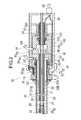
医療デバイス10は、図1~3に示すように、長尺であって回転駆動される駆動シャフト20と、駆動シャフトを収容する内管50と、駆動シャフト20および内管50を収容する外管30と、血栓を切削する切削部40と、ハブ部60とを備えている。As shown in FIGS. 1 to 3, the
駆動シャフト20は、長尺であり、回転力を切削部40に伝達する。駆動シャフト20は、生理食塩液等の液体を遠位側へ送液するための送液ルーメン21が形成されている。送液ルーメン21は、ガイドワイヤを通すガイドワイヤルーメンでもある。駆動シャフト20は、第1駆動シャフト22と、第1駆動シャフト22の近位側に位置する第2駆動シャフト23と、第2駆動シャフト23の近位部に固定される接続部24とを備えている。駆動シャフト20は、さらに、第1駆動シャフト22と第2駆動シャフト23を連結する筒状の連結部25と、保護管26とを備えている。The
第1駆動シャフト22および第2駆動シャフト23は、柔軟で、かつ近位側から作用する回転の動力を遠位側に伝達可能な特性を有する。第1駆動シャフト22および第2駆動シャフト23は、複数の線材を並べて螺旋状に連結した管体である。したがって、第1駆動シャフト22および第2駆動シャフト23は、線材の隙間から流体を通過させる。第1駆動シャフト22および第2駆動シャフト23は、螺旋の巻回方向が逆方向である。第1駆動シャフト22の遠位部に、切削部40が固定されている。The
接続部24は、第2駆動シャフト23の近位部に固定されている。接続部24は、後述する駆動部62から回転トルクを受ける剛直な管体である。接続部24は、駆動部62を貫通し、駆動ロータ62Aおよび図示しない軸受を介して駆動部62の内部で回転する。接続部24の構成材料は、トルクを効果的に伝達できるように、ある程度の剛性を有することが好ましく、例えばステンレス、Ta、Ti、Pt、Au、Wなどの金属材料が好適に使用できる。レーザー加工により、これらの金属材料の外周に螺旋状のスリットや溝を形成し、トルク伝達性を高めることができる。また、ポリエチレン、ポリプロピレンなどのポリオレフィン、ポリアミド、ポリエチレンテレフタレートなどのポリエステル、 (ポリテトラフルオロエチレン(PTFE)、エチレン・テトラフルオロエチレン共重合体(ETFE)等のフッ素系ポリマー、ポリエーテルエーテルケトン(PEEK)、ポリイミドなどの樹脂材料を用いてもよく、剛性を保つため、これらの樹脂材料を上記金属外周に設けてもよい。The connecting
保護管26は、第1駆動シャフト22、第2駆動シャフト23および接続部24の内側を覆う管体である。保護管26は、送液ルーメン21内を通るガイドワイヤが、第1駆動シャフト22、第2駆動シャフト23および接続部24と擦れることを抑制する。保護管26は、第1駆動シャフト22と第2駆動シャフト23の連結部、および後述する第2空間部105の内部で、流体を通過させるために部分的に途切れている。なお、第1駆動シャフト22と第2駆動シャフト23の連結部において、保護管26は連続していてもよい。さらに、部分的に途切れさせる代わりに、保護管26の内面から外面に連通する側孔を設けてもよい。保護管26の近位端は、ハブ部60内でのガイドワイヤの擦れを抑制し、ガイドワイヤを導出するために、ハブ部60の近位端まで延在している。The
駆動シャフト20の第1駆動シャフト22と第2駆動シャフト23の連結部の近傍は、内側(送液ルーメン21)の流体を外側へ通過される中央通過部27である。駆動シャフト20の第2空間部105の内部に位置する部位は、第2空間部105の液体を内側(送液ルーメン21)へ通過される近位通過部28である。駆動シャフト20は、遠位端に、液体を放出する放出開口部29を有している。The vicinity of the connecting portion between the
第1駆動シャフト22および第2駆動シャフト23の構成材料は、例えば、ステンレス、Ta、Ti、Pt、Au、W、ポリエチレン、ポリプロピレンなどのポリオレフィン、ポリアミド、ポリエチレンテレフタレートなどのポリエステル、エチレン・テトラフルオロエチレン共重合体(ETFE)等のフッ素系ポリマー、ポリエーテルエーテルケトン(PEEK)、ポリイミド、などが好適に使用できる。駆動シャフト20は、第1駆動シャフト22および第2駆動シャフト23の2つに分割されなくてもよい。駆動シャフトは、螺旋状の線材により形成されなくてもよい。例えば、駆動シャフトは、螺旋状のスリットや溝をレーザー加工等により形成されてもよい。Constituent materials of the
外管30は、駆動シャフト20および内管50を収容する筒体である。外管30は、切削した血栓等の物体を吸引するための吸引ルーメン31が形成されている。外管30の近位部の外周面には、耐キンクプロテクタ32と、操作部70とが固定されている。耐キンクプロテクタ32は、外管30の近位側におけるキンクを抑制する。外管30は、操作部70に連結される部位よりも近位側の外表面に、後述する第1シール部92および第2支持部93が接している。外管30の操作部70が連結される部位およびさらにその近位側の部位は、剛直である。同様に、操作部70の外管30と連結される部位の少なくとも一部は剛直である。このため、外管30は、操作部70、第1シール部92および第2支持部93と、良好に接することができる。操作部70の第1シール部92および第2支持部93と接する外表面は、低摩擦で接触するように、滑らかに形成されている。操作部70は、ある程度の強度を有することが好ましく、構成材料として、ABS樹脂、ポリカーボネート(PC)、ポリメチルメタクリレート(PMMA)、ポリアセタール(POM)、ポリフェニルサルフォン(PPSU)、ポリエチレン(PE)、カーボンファイバー、ポリエーテルエーテルケトン(PEEK)などの樹脂が好適に使用できる。ステンレス、Ta、Ti、Pt、Au、Wなどの金属、すなわち高密度材料を用いることで、回転操作の安定化を図ってもよい。操作部70の術者が触れる外表面は、高摩擦表面を形成してもよい。これにより、術者による確実かつ正確な回転トルク操作を実現できる。高摩擦表面は、ブチルゴム、イソプレンゴム、ブタジエン系ゴム、シリコーンゴム、天然ゴム、ポリ塩化ビニル(PVC)、ポリプロピレン(PP)、ポリエチレン(PE)など生体適合性のある高摩擦材料により形成してもよいし、外表面に凹凸を設けて術者の指が引っかかりやすくするように形成してもよい。外管30の近位部の外表面は、第1シール部92および第2支持部93と接する部位を除き、高い摩擦力を有している。すなわち、外管30の外表面は、遠位側から低摩擦抵抗、高摩擦抵抗、低摩擦抵抗の順番で形成される。このため、外管30を把持して操作部70の回転トルクが医療デバイス10の遠位側に伝わるように支持することができ、あるいは外管30自体により医療デバイス10の遠位側に回転トルクを作用させることが容易である。具体的には、外管30の体外露出部分における捩れや湾曲を解消することで、医療デバイス10の遠位端に操作部70の回転トルクを確実に伝えることができる。The
外管30の遠位部は、生体管腔内で曲がるように、近位部よりも柔軟であることが好ましい。外管30の遠位部は、柔軟性を付与するために、例えば、螺旋状のスリットや溝をレーザー加工等により形成されてもよい。外管30の遠位部の加工された外表面は、樹脂等が被覆されてもよい。The distal portion of the
外管30は、遠位端に、切削した物体や、駆動シャフト20から放出した液体を吸引する吸引開口部33を有している。外管30の遠位端は、切削部40の近位側に位置している。外管30は、遠位部に、湾曲部34を有している。湾曲部34は、外管30を回転させることで、外管30の遠位端および切削部40の位置および向きを変更するために利用できる。外管30は、近位端に、後述する第1空間部95の内部で開口する基端開口部35を有している。The
外管30は、複数種類の異なる部材から構成されてもよい。例えば、樹脂製の管状部材30Bと、管状部材30Bの近位部の外周面に固定される補強管30A(図2の一点鎖線を参照)とから構成されてもよい。補強管30Aの材料は、管状部材30Bの材料よりも高密度の材料であり、例えばステンレス等の金属である。補強管30Aの外周面に、第1シール部92が接触する。The
補強管30Aの内径は、管状部材30Bの内径よりも大きい。このため、補強管30Aの内側に、管状部材30Bを配置して固定できる。管状部材30Bの補強管30Aが配置される部位の外径は、管状部材30Bの他の部位の外径よりも小さくてもよい。これにより、管状部材30Bに補強管30Aが配置された外管30は、全体にわたって一定の外径となることができる。または、管状部材30Bの外径は、全体にわたって一定であってもよい。これにより、管状部材30Bに補強管30Aが配置された外管30の外径は、補強管30Aが配置される部位で大きくなる。補強管30Aの遠位端は、耐キンクプロテクタ32、操作部70、第1支持部67またはケーシング61の内部に配置される。これにより、外管30は、補強管30Aと管状部材30Bとの境界での折れ曲がりを抑制できる。補強管30Aが設けられる外管30は、操作部70から作用する回転力を、効果的に伝達させることができる。The inner diameter of the reinforcing
外管30の構成材料は、ある程度の強度を有することが好ましく、例えば、ステンレス、Ta、Ti、Pt、Au、W、形状記憶合金などが好適に使用できる。外管30の構成材料は、ABS樹脂、ポリカーボネート(PC)、ポリメチルメタクリレート(PMMA)、ポリアセタール(POM)、ポリフェニルサルフォン(PPSU)、ポリエチレン(PE)、カーボンファイバー、ポリエーテルエーテルケトン(PEEK)などのエンジニアリングプラスチック等の樹脂でもよい。The constituent material of the
切削部40は、血栓等の物体を切削するための部材である。切削部40は、第1駆動シャフト22の遠位部の外周面に固定されている。切削部40は、表面に、微小な砥粒を多数有している。または、切削部40は、鋭利な刃を備えてもよい。The cutting
切削部40の構成材料は、血栓を切削できる程度の強度を有することが好ましく、例えば、ステンレス、Ta、Ti、Pt、Au、W、形状記憶合金、超鋼合金などが好適に使用できる。The constituent material of the cutting
内管50は、外管30の内部で駆動シャフト20を囲んでいる柔軟な管体である。内管50は、内面と外面の間で流体を通過させる駆動シャフト20を囲むことで、駆動シャフト20を通過して、流体が送液ルーメン21から吸引ルーメン31へショートカットすることを抑制する。内管50は、近位側内管51と、遠位側内管52とを備えている。近位側内管51の基端部は、ハブ部60に固定されている。近位側内管51の遠位部は、駆動シャフト20の中央通過部27の近位側に位置している。近位側内管51は、ハブ部60の吸引圧力および送液圧力を、中央通過部27まで効果的に伝達する。遠位側内管52は、連結部25よりも遠位側で、他の部材に拘束されずに自由に回転可能となっている。遠位側内管52は、中央通過部27まで伝わったハブ部60の吸引圧力および送液圧力を、さらに遠位側まで効果的に伝達する。内管50の構成材料は、ある程度の柔軟性と低摩擦性を有することが望ましく、ポリエーテルエーテルケトン(PEEK)、PTFE・ETFE等のフッ素系ポリマー、ポリメチルメタクリレート(PMMA)、ポリエチレン(PE)、ポリエーテルブロックアシドコポリマー(PEBAX)、ポリイミドおよびその組み合わせが好適に使用できる。The
ハブ部60は、ケーシング61と、駆動部62と、スイッチ63と、送液ポート64と、吸引ポート65と、電気ケーブル66とを備えている。ハブ部60は、さらに、操作部70と、回転規制部80と、吸引部90と、送液部100とを備えている。The
ケーシング61は、駆動部62、送液部100および吸引部90を収容している。ケーシング61の遠位部には、操作部70を回転可能に支持する軸受状の第1支持部67が形成されている。第1支持部67はケーシング61と別体でもよい。The
駆動部62は、例えば中空モータである。駆動部62は、電気ケーブル66を介して外部から供給される電力によって回転する。駆動部62には、駆動シャフト20の接続部24が貫通している。接続部24は、中空モータの中空の駆動ロータ62Aに、軸受等を介さずに直結されている。したがって、駆動部62は、駆動シャフト20をぶれずに高速で回転させることができる。接続部24の外径は、駆動ロータ62Aの外径よりも小さい。このため、接続部24の外周面に後述する送液シール部102を接触させるよりも、接続部24の外周面に送液シール部102を接触させる方が、送液シール部102の内径が小さくなる。したがって、接続部24と送液シール部102の摩擦抵抗が小さくなり、密封性を高めることができる。駆動部62の回転速度は、特に限定されないが、例えば5,000~200,000rpmである。また、製造上の組立性や電気的安全性向上のため、中空モータの中空の駆動ロータ62Aと、駆動シャフト20の間に他の管体を配置してもよい。当該管体は、金属、非導電性の金属、樹脂などの絶縁材料で構成されることができる。駆動部62に中空モータを用いることで、駆動部62と駆動シャフト20の回転軸さらに、外管30の回転軸をすべて同軸化することができる。これにより、駆動シャフト20の回転を高精度化し、安定化できるだけでなく、ギアなどによる駆動伝達部品による発熱、騒音の問題を解消できる。さらにハブ部60も小型化するため、術者がハブ部60を片手で操作できるようになる。なお、接続部24は、中空モータの構成の一部である駆動ロータであってもよい。The
電気ケーブル66は、外部の電源または制御装置に接続可能である。スイッチ63は、術者が駆動部62の駆動および停止を操作する部位である。スイッチ63は、ケーシング61の遠位部の外面に位置している。このため、術者は、ケーシング61の遠位部に位置する操作部70、回転規制部80およびスイッチ63を片手で操作できる。The
操作部70は、術者が指で操作して、外管30に回転トルクを作用させる部位である。操作部70は、外管30の近位部の外周面に固定されている。操作部70は、操作ダイヤル71と、受け溝72と、複数の係合部73とを備えている。操作ダイヤル71は、術者が指で操作する略円盤状の部位である。操作ダイヤル71の外周面は、操作しやすいように、高い摩擦抵抗を有している。受け溝72は、第1支持部67により回転可能に保持される部位である。第1支持部67と操作部70の接触面積は、第2支持部93と外管30の接触面積よりも大きい。複数の係合部73は、操作ダイヤル71の近位側の面に周方向に並ぶ凹部である。係合部73には、回転規制部80が嵌合可能である。受け溝72の第1支持部67に対する摩擦抵抗は、外管30の向きを保持できる程度に大きい。したがって、操作ダイヤル71が術者によって回転された後、指を離すと、受け溝72と第1支持部67の摩擦抵抗により、回転された位置が保持される。なお、外管30の外周面と第1シール部92の内周面の摩擦抵抗、あるいは外管30の外周面と第2支持部93の内周面の摩擦抵抗、あるいは操作部70の外周面と第1支持部67の内周面との摩擦抵抗を外管30の向きを保持する程度に大きく設定することで、同様の効果を得ることも可能である。これにより部品点数を減らし、構造を単純化することができる。具体的には、各々の外周面と内周面に凹凸構造を形成し、前記凹凸構造の摩擦抵抗は、外管30の向きを保持できる程度に大きく、摩擦抵抗を超える力によって変形する。The
回転規制部80は、操作部70の回転を規制する部位である。回転規制部80は、ケーシング61の遠位部に、ケーシング61に対して摺動可能に設けられている。回転規制部80は、術者が指で操作する規制操作部81と、操作部70の係合部73に係合可能な突起部82とを備えている。術者が規制操作部81を遠位側へ移動させると、突起部82が遠位側へ移動し、突起部82が係合部73の1つに嵌合する。これにより、操作部70が回転不能となる。術者が規制操作部81を遠位側へ移動させると、突起部82が近位側へ移動し、突起部82が係合部73から抜ける。これにより、操作部70が回転可能となる。上記では、嵌合により回転不能としたが、突起部82または係合部73を変形可能として、操作ダイヤル71が一定以上の回転トルクを受けた場合にのみ、回転可能としてもよい。また、上記一定以上の回転トルクは、外管30の向きを保持できる程度に設定する。これにより規制操作部81が無い場合でも、外管30が回転された位置を保持しながら、術者が必要に応じて外管30の向きを変更できる。The
送液ポート64は、外部の送液ポンプ等の送液源11に接続可能である。送液ポート64は、送液源11から、生体内へ送液する生理食塩液等の液体を供給される。送液ポート64は、供給された液体を、送液部100へ搬送する。送液源11は、送液圧力が生成できるものであればよく、ポンプ、点滴塔に吊られたバッグ、シリンジなどを用いることができる。ポンプ等のように、能動的に送液可能な送液源11を用いることで、送液量を安定化させることができる。The
吸引ポート65は、外部の吸引ポンプ等の吸引源12に接続可能である。吸引ポート65は、吸引源12により吸引されて、吸引部90の内部の流体等を吸引源12へ向かって搬送する。吸引源12は、吸引圧力が生成できるものであればよく、ポンプ、シリンジなどを用いることができる。ポンプ等のように、能動的に吸引可能な吸引源12を用いることで、吸引圧を高め、吸引力を安定化・向上させることができる。The
吸引部90は、外管30の吸引ルーメン31に吸引圧力を作用させる部位である。吸引部90は、第1ハウジング91と、第1シール部92と、第2支持部93とを備えている。The
第1ハウジング91は、流体を外部へ放出する吸引口94と、吸引口94に連通する第1空間部95とを備えている。第1空間部95の内部には、外管30の基端開口部35が位置している。第1空間部95の近位部には、近位側内管51が固定されている。吸引口94は、吸引ポート65に接続されている。The
第1シール部92は、第1空間部95の遠位部で、第1ハウジング91と外管30の間に位置している。第1シール部92は、第1空間部95の内部に、外部の空気が流入することを抑制する。さらに、第1シール部92は、外管30を回転可能に支持する。第1シール部92は、寸法精度が高く、面性状が滑らかであり、かつ柔軟性(密着性)が高い。これにより、第1シール部92は、接触する対象に対して、高い寸法精度で隙間なく密着し、密封性に優れる。第1シール部92の構成材料は、例えば天然ゴム、合成ゴム、シリコーン樹脂等が挙げられる。なお、第1シール部92は、第1空間部95の近位部に設けられてもよい。これにより、ハブ部60の全長が長くなる代わりに、外管30をより高精度に回転支持できる。The
第2支持部93は、第1空間部95の遠位部で、第1ハウジング91と外管30の間に位置している。第2支持部93は、第1シール部92の近位側に位置している。第2支持部93は、摩擦抵抗が低いことが好ましい。第2支持部93の構成材料は、例えば、超高分子ポリエチレン、ポリエステル、ポリアミド、ポリテトラフルオロエチレン等のフッ素系樹脂、ABS樹脂、ポリアセタール(POM)、ポリカーボネート(PC)、さらには、これらのうちの2種以上を組合せたもの(ポリマーアロイ、ポリマーブレンド、積層体等)が挙げられる。The
送液部100は、吸引部90の近位側であって、駆動部62の遠位側に位置している。送液部100は、駆動シャフト20の送液ルーメン21に液体を送る部位である。送液部100は、第2ハウジング101と、送液シール部102と、固定部材103とを備えている。The
第2ハウジング101は、外部から液体を送液される送液口104と、送液口104に連通する第2空間部105とを備えている。第2空間部105の内部には、駆動シャフト20が貫通している。第2空間部105の内部には、液体を送液ルーメン21へ通す近位通過部28が位置している。送液口104は、送液ポート64に接続されている。The
送液シール部102は、第2空間部105の近位部で、第2ハウジング101と、駆動シャフト20の接続部24との間に位置している。送液シール部102は、第2空間部105の内部の加圧された液体が、外部へ流出することを抑制する。送液シール部102は、高速で回転する接続部24と接触するため、摩擦抵抗が低く、耐熱性が高く、線膨張率が低く、耐摩耗性が高いことが好ましい。送液シール部102の構成材料は、例えば、超高分子ポリエチレン、ポリエステル、ポリアミド、ポリテトラフルオロエチレン等のフッ素系樹脂、ポリエーテルエーテルケトン(PEEK)、ポリアセタール(POM)、シリコーンゴム、さらには、これらのうちの2種以上を組合せたもの(ポリマーアロイ、ポリマーブレンド、積層体等)が挙げられる。The liquid
固定部材103は、送液シール部102を第2ハウジング101に対して固定する筒状の部材である。固定部材103は、第2ハウジング101の近位側から第2空間部105の内部に向かって入り込んでいる。固定部材103の遠位端は、送液シール部102の近位側の面に接触して、送液シール部102を支持している。The fixing
次に、第1実施形態に係る医療デバイス10の使用方法を、図4に示すフローチャートを参照しつつ説明する。ここでは、当該使用方法を、血管内の血栓等の病変部を破壊して吸引する場合を例として説明する。Next, a method of using the
初めに、術者は、ガイドワイヤWを血管に挿入し、病変部Sの近傍へ到達させる。次に、術者は、医療デバイス10の送液ルーメン21に、ガイドワイヤWの近位端を挿入する。この後、図5(A)に示すように、ガイドワイヤWをガイドとして、医療デバイス10の切削部40を、病変部Sの近傍まで移動させる(ステップS10)。First, the surgeon inserts the guide wire W into the blood vessel and reaches the vicinity of the lesioned part S. Next, the surgeon inserts the proximal end of the guide wire W into the
次に、術者は、スイッチ63を操作し、送液および吸引を開始する(ステップS11)。すなわち、術者は、外部の送液源11および吸引源12を作動させる。これと同時あるいは一定時間の経過後、駆動シャフト20を介して切削部40を回転させる(ステップS12)。この動作は電気ケーブル66に接続された装置によって制御したり、ハブ部60内に制御部を設けて制御したりすることができる。これにより、術者は、病変部Sを切削できる(ステップS13)。Next, the operator operates the
術者は、図2に示すように、切削部40の位置を周方向へ変更したい場合に、操作部70を操作することができる。術者は、操作部70を操作する前に、回転規制部80の規制操作部81を近位側へ移動させる(ステップS14)。これにより、突起部82が操作部70の係合部73から抜ける。このため、操作部70が回転可能となる。次に、操作ダイヤル71を回転させると、第1支持部67に支持されている操作部70が回転する。これにより、外管30が回転する。外管30を回転させると、外管30の湾曲部34の方向が変わり、図5(B)に示すように、切削部40の位置を変更できる。したがって、大きく回転させることが困難なハブ部60の全体を回転させることなく、切削部40の方向を変更しつつ切削できる(ステップS15)。さらに、術者は、ハブ部60の全体または体外に露出した外管30を移動させて、外管30を、血管の長尺方向に沿って往復移動させる。これにより、図5(C)に示すように、切削部40により、病変部Sを血管の長尺方向に沿って切削できる(ステップS16)。As shown in FIG. 2, the surgeon can operate the
術者が操作部70を操作する際には、図2に示すように、操作部70に指から力が作用する。操作部70は、第1支持部67により支持されている。さらに、操作部70が固定されている外管30は、第1シール部92および第2支持部93により支持されている。このため、第1シール部92と外管30の位置が適切に維持される。したがって、第1シール部92の密封が適切に維持され、第1ハウジング91と外管30の間から空気が第1空間部95に流入することが抑制される。When the surgeon operates the
送液が開始されると、送液口104から第2空間部105に流入した生理食塩液が、駆動シャフト20の近位通過部28を通過して、送液ルーメン21に入る。なお、駆動シャフト20と第2ハウジング101の間は、送液シール部102により密封されている。このため、第2空間部105の生理食塩液は、駆動シャフト20と第2ハウジング101の間から外部へ流出し難くなる。したがって、第2空間部105は、高い送液圧力を維持できる。When liquid feeding is started, the physiological saline solution that has flowed into the
送液ルーメン21に入った生理食塩液は、遠位側へ移動する。なお、駆動シャフト20の外側には、近位側内管51が位置している。このため、送液ルーメン21の内部の生理食塩液は、吸引ルーメン31へショートカットすることなく、中央通過部27まで効果的に移動できる。送液ルーメン21の内部の生理食塩液の一部は、中央通過部27まで到達すると、吸引ルーメン31へ移動する。The physiological saline solution that has entered the
送液ルーメン21の内部の生理食塩液の残りは、さらに遠位側へ移動し、図3に示すように、放出開口部29から切削部40の内部を通って血管内に放出される。血管内に入った生理食塩液の一部は、血液および切削された物体と共に、外管30の吸引ルーメン31へ吸引される(ステップS17)。吸引ルーメン31に入った物体および流体は、吸引ルーメン31を近位側へ移動する。吸引ルーメン31に入った流体は、図2に示すように、中央通過部27で合流する生理食塩液によって薄められる。このため、吸引ルーメン31内で血栓が形成されることを抑制し、吸引物の粘度を低下させることで吸引量を増大させることができる。したがって、医療デバイス10の吸引力の低下や損傷を抑制しつつ、吸引性能を高められる。また、医療デバイス10内に形成された血栓が、生体管腔内に流出することを抑制できる。吸引ルーメン31に入った流体は、吸引部90の第1空間部95へ到達すると、吸引口94から外部の吸引源12へ放出される。なお、吸引部90の第1ハウジング91と外管30の間は、第1シール部92によって密封されている。このため、第1ハウジング91と外管30の間から空気が流入することを抑制できる。このため、第1空間部95の吸引圧力の低下を抑制できる。このときの吸引圧力は、絶対真空0kPaに対して、0~90kPa、好ましくは0kPa~50kPaである。The remainder of the physiological saline inside the
病変部Sの切削および吸引が完了した後、術者は、スイッチ63を押す。これにより、駆動シャフト20の回転が停止され、切削部40による切削が停止される(ステップS18)。これと同時または一定時間の経過後、送液および吸引を停止させる(ステップS19)。すなわち、外部の送液源11および吸引源12を停止させる。この動作は電気ケーブル66に接続された装置によって制御したり、ハブ部60内に制御部を設けて制御したりすることができる。この後、医療デバイス10を血管から抜去し、処置が完了する(ステップS20)。After completion of cutting and suction of the lesioned part S, the operator presses the
以上のように、第1の実施形態に係る医療デバイス10は、生体管腔内の物体を除去する医療デバイス10であって、回転可能である駆動シャフト20と、駆動シャフト20を回転可能に収容する外管30と、駆動シャフト20の遠位部に固定されて物体を切削する切削部40と、駆動シャフト20および外管30の近位部が配置されるハブ部60と、を有し、ハブ部60は、外管30の外周面に固定されて外管30を回転させる操作部70と、操作部70を回転可能に支持する第1支持部67と、流体を外部へ放出する吸引口94が形成され、当該吸引口94に外管30の吸引ルーメン31が連通する第1ハウジング91と、第1ハウジング91および外管30の間、または、第1ハウジング91および操作部70の間に配置される第1シール部92と、を有し、第1支持部67と第1シール部92が軸方向に沿って並んで配置される。As described above, the
上記のように構成した医療デバイス10は、外管30の向きを変える回転操作時に指から力が作用する操作部70が第1支持部67により支持されるため、外管30の回転中心が安定する。さらに、第1シール部92も外管30を支持するため、外管30の回転中心がさらに安定する。これにより、外管30を回転させる際に、第1シール部92の外管30または操作部70に対する密着性の低下を抑制できる。このため、第1シール部92から第1ハウジング91の内部への空気の流入を抑制でき、吸引ルーメン31の吸引圧力を適切に維持できる。したがって、医療デバイス10は、生体管腔内で切削部40の位置を変更しつつ、切削した物体を良好に吸引できる。また、外管30の軸方向に沿って、第1支持部67と第1シール部92が並んで配置されることにより、外管30の回転中心をさらに安定させることができる。In the
また、第1支持部67は、第1シール部92に対して遠位側に配置される。これにより、第1シール部92は、操作部70から強い力が作用する第1支持部67の近位側で、第1支持部67を補助するように、外管30を効果的に支持できる。したがって、外管30の回転中心が安定し、かつ第1シール部92の密封性が損なわれ難い。Further, the
また、ハブ部60は、第1ハウジング91および第2ハウジング101を収容するケーシング61を有し、第1支持部67は、ケーシング61の一部である。これにより、回転操作される操作部70がケーシング61に支持されるため、操作部70を操作しやすくなる。また、第1ハウジング91および第2ハウジング101を収容するケーシング61によって操作部70が支持されるため、操作部70が、第1ハウジング91および第2ハウジング101に対して適切な位置を維持しやすい。このため、第1支持部67が操作部70を効果的に支持でき、外管30の回転中心が安定する。The
また、ハブ部60は、第1支持部67よりも近位側に第2支持部93を有し、第2支持部93は、外管30を第1ハウジング91に対して回転可能に支持する。れにより、第1支持部67および第2支持部93が、外管30の回転中心を安定させる。このため、操作部70の回転操作時において、第1シール部92の外管30または操作部70に対する密着性の低下を効果的に抑制できる。The
また、第2支持部93は、第1シール部92よりも近位側に位置する。これにより、第1支持部67および第2支持部93が、第1シール部92を軸方向に挟む位置関係となる。このため、操作部70の回転操作時において、第1シール部92の外管30または操作部70に対する密着性の低下をさらに効果的に抑制できる。In addition, the
また、第1支持部67の操作部70に対する接触面積は、第2支持部93の操作部70または外管30に対する接触面積よりも大きい。これにより、回転操作時に指から操作部70に作用する力を、接触面積の大きい第1支持部67により効果的に受け止めることができる。これにより、第1シール部92の外管30または操作部70に対する密着性の低下を効果的に抑制できる。In addition, the contact area of the
また、医療デバイス10は、操作部70の第1ハウジング91に対する回転を規制する回転規制部80を有する。これにより、操作部70の回転を規制して、生体内の外管30や切削部40の位置を、望ましい位置で固定できる。Further, the
また、医療デバイス10は、前記吸引口94に接続されて能動的に吸引を行う吸引源12を有する。これにより、医療デバイス10は、吸引圧を高め、吸引力を安定化・向上させることができる。The
また、外管30の近位部の外表面の少なくとも一部は、遠位部の外表面に比べて高摩擦である。これにより、術者が、外管30を把持して、操作部70の回転トルクが医療デバイス10の遠位側に伝わるように支持することができ、あるいは外管30自体に回転トルクを作用させることが容易である。In addition, at least a part of the outer surface of the proximal portion of the
また、ハブ部60は、駆動シャフト20を回転させる中空モータである駆動部62を有し、記駆動シャフト20は駆動部62を貫通し、駆動シャフト20の回転軸と駆動部62の回転軸は一致する。これにより、駆動シャフト20の回転を高精度化・安定化させることができる。また、ハブ部60が小型化し、術者が片手でハブ部60を操作できる。The
また、本発明は、処置方法(治療方法)をも提供する。当該処置方法は、生体管腔内の病変部Sを切削する切削部40が駆動シャフト20の遠位部に設けられ、駆動シャフト20を回転可能に収容する外管30により切削した病変部Sを吸引可能な医療デバイス10による処置方法であって、切削部40を病変部Sの近傍まで移動するステップS10と、外管30の内部に吸引圧力を作用させるステップS11と、曲がっている外管30を回転させて生体管腔内の切削部40の位置を変更するステップS15、S16と、駆動シャフト20を回転させて切削部40により病変部Sを切削するステップS15、S16と、切削された病変部Sを外管30の遠位部から吸引するステップS17と、医療デバイス10を生体管腔から抜去するステップS20と、を有する。The present invention also provides a treatment method (treatment method). In this treatment method, a cutting
上記のように構成した処置方法は、医療デバイス10の曲がっている外管30を回転させて切削部40の位置を変更できるため、生体管腔内の広い範囲の病変部Sを、効果的に切削して除去できる。Since the treatment method configured as described above can rotate the bent
また、前記切削するステップにおいて、生体管腔内で曲がっている外管30を回転させつつ切削部40により病変部Sを切削してもよい。これにより、曲がっている外管30の回転によって切削部40の位置を周方向へ効果的に変更しつつ、病変部Sを切削できる。したがって、生体管腔内の広い範囲の病変部Sを切削部40により効果的に切削して除去できる。In the cutting step, the lesioned part S may be cut by the cutting
また、前記切削するステップにおいて、曲がっている外管30を回転させて切削部40の周方向の位置を位置決めした後に、外管30を生体管腔の長尺方向に沿って往復移動させてもよい。これにより、生体管腔内の長尺方向の広い範囲の病変部Sを、切削部40により効果的に切削して除去できる。Further, in the cutting step, after the bent
また、前記切削するステップにおいて、駆動シャフト20の内腔である送液ルーメン21を介して流体を遠位側へ送液してもよい。これにより、駆動シャフト20の送液ルーメン21を利用して流体を遠位側へ供給しつつ、切削した病変部Sを吸引できる。このため、切削した病変部Sを、供給した流体とともに効果的に吸引して除去できる。
<第2実施形態>Further, in the cutting step, the fluid may be fed to the distal side via the
Second Embodiment
第2実施形態に係る医療デバイス110は、図6、7(A)に示すように、回転規制部130の構成が、第1実施形態に係る医療デバイス10と異なる。なお、第1実施形態と同様の機能を有する部位には、同一の符号を付し、説明を省略する。The
医療デバイス110の操作部120は、軸直交断面が多角形の多角部121を有している。多角部121の外周面に形成される複数の面は、係合部122である。The
回転規制部130は、ケーシング61の遠位部から遠位方向へ突出する板バネ状の弾性部131と、弾性部131から突出する突起部132を備えている。弾性部131は、ケーシング61から多角部121の外側まで延在している。突起部132は、弾性部131から多角部121に向かって突出し、係合部122に当接している。弾性部131は、突起部132を、係合部122に向かって付勢している。The
術者が操作ダイヤル71を回転させると、図7(B)に示すように、突起部132の係合部122に対する接触位置が変化する。突起部132が、2つの係合部122の境界、すなわち多角形の角部123を乗り越える際に、弾性部131が最も撓む。このため、突起部132が角部123を乗り越える際に、操作部120の回転抵抗が最も大きくなる。したがって、術者が操作ダイヤル71の回転操作を停止すると、突起部132は次の角部123を乗り越えず、回転が規制される。したがって、回転規制部130は、操作部120および外管30の回転を、ケーシング61および第1ハウジング91に対して規制できる。これにより、術者が操作部120を操作しない状態では、切削部40の位置が適切に保持される。このため、医療デバイス110の操作性が向上する。
<第3実施形態>When the operator rotates the
<Third Embodiment>
第3実施形態に係る医療デバイス140は、図8に示すように、補助ハウジング150が設けられる点で、第1実施形態に係る医療デバイス10と異なる。なお、第1実施形態と同様の機能を有する部位には、同一の符号を付し、説明を省略する。The
医療デバイス140は、ハブ部60の第1ハウジング91の遠位側に、補助ハウジング150を備えている。補助ハウジング150は、外部から液体を送液される補助送液口152と、補助送液口152に連通する補助空間部153とを備えている。補助空間部153は、第1ハウジング91の第1シール部92の遠位側に位置している。補助空間部153の内部には外管30、内管50および駆動シャフト20が貫通している。補助空間部153の遠位側には、第2シール部154が配置されている。The
第2シール部154は、補助空間部153の遠位部で、補助ハウジング150と外管30の間に位置している。第2シール部154は、補助空間部153の内部の加圧された液体が、外部へ流出することを抑制する。さらに、第2シール部154は、外管30を支持している。第2シール部154は、寸法精度が高く、面性状が滑らかであり、かつ柔軟性(密着性)が高い。これにより、第2シール部154は、接触する対象に対して、高い寸法精度で隙間なく密着し、密封性に優れる。第2シール部154の構成材料は、例えば天然ゴム、合成ゴム、シリコーン樹脂等が挙げられる。The
補助送液口152は、送液ポート64に接続される補助ポート155から送液される。補助ポート155からの液体供給量が過多になると、第2シール部154を介して液体が必要以上に流入する。その結果、医療デバイス140の遠位端からの吸引量が減り、本来あるべき吸引性能が低下する。補助ポート155は、送液ポート64よりも流路が狭い。このため、補助ポート155の圧力損失により、補助送液口152に到達する液体は、送液部100の送液口104に到達する液体よりも少ない。したがって、補助送液口152を液体を供給しつつも、その供給が過多にならず、医療デバイス140の遠位端からの吸引量を損なうことなく治療ができる。同時に、送液部100の第2空間部105を液体で満たすことができる。The auxiliary liquid supply port 152 is supplied from an
吸引部90で吸引が開始されると、吸引された病変部等の物体や液体が、吸引ルーメン31を通って、吸引部90の第1空間部95へ到達する。第1空間部95に到達した物体や液体は、吸引口94から外部の吸引源12へ放出される。吸引部90の第1ハウジング91と外管30の間は、第1シール部92によって密封されている。このため、第1ハウジング91と外管30の間から空気が流入することを抑制できる。また、第1シール部92の遠位側には、補助空間部153が設けられている。補助空間部153は、補助ポート155を介して補助送液口152から供給された生理食塩液等の液体が満たされている。そして、補助空間部153の液体は、外管30と接する第1シール部92および第2シール部154により密封されている。したがって、仮に、第1シール部92の密封性が低下しても、第1シール部92と外管30の間の隙間を通って第1空間部95に入る流体は、空気ではなく、補助空間部153を満たしている液体である。このため、第1空間部95に空気が流入することを抑制できる。したがって、第1空間部95の吸引圧力の低下を確実に抑制できる。When suction is started by the
なお、補助空間部153は、流体が密封された状態で補助送液口152が塞がれていてもよい。また補助空間部153をプライミングしやすいように、第1シール部92および第2シール部154の少なくとも一方は、密封性が低く、液体を流通させやすくてもよい。In the
本発明は、上述した実施形態のみに限定されるものではなく、本発明の技術的思想内において当業者により種々変更が可能である。例えば、医療デバイスが挿入される生体管腔は、血管に限定されず、例えば、脈管、尿管、胆管、卵管、肝管等であってもよい。したがって、破壊する物体は、血栓でなくてもよい。The present invention is not limited to the above-described embodiments, and various modifications can be made by those skilled in the art within the technical idea of the present invention. For example, a living body lumen into which a medical device is inserted is not limited to a blood vessel, and may be, for example, a vascular tube, a ureter, a bile duct, a fallopian tube, a hepatic tube, or the like. Therefore, the object to be destroyed need not be a thrombus.
また、第1ハウジング91、第2ハウジング101および補助ハウジング150は、一体的に形成されてもよい。The
また、吸引部90の吸引口94は、吸引源12に接続されず、大気に開放されてもよい。このような構成であっても、生体管腔内の圧力が大気圧よりも高い場合、吸引部90は、生体管腔内の物体を吸引できる。Further, the
なお、本出願は、2018年3月28日に出願された日本特許出願番号2018-062327号に基づいており、それらの開示内容は、参照され、全体として、組み入れられている。Note that this application is based on Japanese Patent Application No. 2018-062327 filed on Mar. 28, 2018, the disclosures of which are incorporated by reference in their entirety.
10、110、140 医療デバイス
11 送液源
12 吸引源
20 駆動シャフト
30 外管
34 湾曲部
40 切削部
60 ハブ部
61 ケーシング
67 第1支持部
70、120 操作部
80、130 回転規制部
90 吸引部
91 第1ハウジング
92 第1シール部
93 第2支持部
94 吸引口
95 第1空間部
100 送液部
101 第2ハウジング
102 送液シール部
104 送液口
105 第2空間部
150 補助ハウジング
152 補助送液口
153 補助空間部
154 第2シール部DESCRIPTION OF SYMBOLS 10,110,140
Claims (14)
Translated fromJapanese回転可能である駆動シャフトと、
前記駆動シャフトを回転可能に収容する外管と、
前記駆動シャフトの遠位部に固定されて物体を切削する切削部と、
前記駆動シャフトおよび外管の近位部が配置されるハブ部と、を有し、
前記ハブ部は、
前記外管の外周面に固定されて前記外管を回転させる操作部と、
前記操作部を回転可能に支持する第1支持部と、
流体を外部へ放出する吸引口が形成され、当該吸引口に前記外管の吸引ルーメンが連通するハウジングと、
前記ハウジングおよび外管の間、または、前記ハウジングおよび操作部の間に配置される第1シール部と、を有し、
前記第1支持部と前記第1シール部が軸方向に沿って並んで配置される医療デバイス。A medical device for removing an object in a living body lumen,
A drive shaft that is rotatable;
An outer tube that rotatably accommodates the drive shaft;
A cutting portion fixed to a distal portion of the drive shaft and cutting an object;
A hub portion on which the drive shaft and a proximal portion of the outer tube are disposed,
The hub portion is
An operation unit that is fixed to the outer peripheral surface of the outer tube and rotates the outer tube;
A first support portion that rotatably supports the operation portion;
A housing in which a suction port for discharging fluid to the outside is formed, and the suction lumen of the outer tube communicates with the suction port;
A first seal portion disposed between the housing and the outer tube, or between the housing and the operation portion,
The medical device in which the first support portion and the first seal portion are arranged along the axial direction.
前記第1支持部は、前記ケーシングの一部である請求項1または2に記載の医療デバイス。The hub portion has a casing for housing the housing;
The medical device according to claim 1, wherein the first support part is a part of the casing.
前記第2支持部は、前記外管を前記ハウジングに対して回転可能に支持する請求項1~3のいずれか1項に記載の医療デバイス。The hub portion has a second support portion on the proximal side of the first support portion,
The medical device according to any one of claims 1 to 3, wherein the second support portion rotatably supports the outer tube with respect to the housing.
前記補助空間部は、液体を供給される補助送液口を有し、
前記補助空間部の遠位側と前記外管の間に第2シール部が配置される請求項1~6のいずれか1項に記載の医療デバイス。The housing is formed with an auxiliary space portion on the distal side of the first seal portion,
The auxiliary space has an auxiliary liquid supply port to which a liquid is supplied,
The medical device according to any one of claims 1 to 6, wherein a second seal portion is disposed between a distal side of the auxiliary space portion and the outer tube.
前記駆動シャフトは前記駆動部を貫通し、前記駆動シャフトの回転軸と前記駆動部の回転軸は一致する請求項1~10のいずれか1項に記載の医療デバイス。The hub portion has a drive portion that is a hollow motor that rotates the drive shaft,
The medical device according to any one of claims 1 to 10, wherein the drive shaft passes through the drive unit, and a rotation axis of the drive shaft coincides with a rotation axis of the drive unit.
前記切削部を病変部の近傍まで移動するステップと、
前記外管の内部に吸引圧力を作用させるステップと、
曲がっている前記外管を回転させて生体管腔内の前記切削部の位置を変更するステップと、
前記駆動シャフトを回転させて前記切削部により前記病変部を切削するステップと、
切削された病変部を前記外管の遠位部から吸引するステップと、
前記医療デバイスを生体管腔から抜去するステップと、を有する処置方法。A treatment method using a medical device capable of aspirating a lesioned part cut by an outer tube that rotatably accommodates the driving shaft is provided with a cutting part for cutting a lesioned part in a living body lumen at the distal part of the driving shaft. And
Moving the cutting part to the vicinity of the lesion;
Applying a suction pressure to the inside of the outer tube;
Rotating the bent outer tube to change the position of the cutting portion in the living body lumen;
Rotating the drive shaft to cut the lesion by the cutting part;
Aspirating the cut lesion from the distal portion of the outer tube;
Removing the medical device from the body lumen.
Priority Applications (4)
| Application Number | Priority Date | Filing Date | Title |
|---|---|---|---|
| JP2020510042AJP7296945B2 (en) | 2018-03-28 | 2019-03-25 | medical device |
| US17/013,913US11751898B2 (en) | 2018-03-28 | 2020-09-08 | Medical device and treatment method |
| JP2023097260AJP7607082B2 (en) | 2018-03-28 | 2023-06-13 | Medical Devices |
| US18/363,062US12114884B2 (en) | 2018-03-28 | 2023-08-01 | Medical device and treatment method |
Applications Claiming Priority (2)
| Application Number | Priority Date | Filing Date | Title |
|---|---|---|---|
| JP2018062327 | 2018-03-28 | ||
| JP2018-062327 | 2018-03-28 |
Related Child Applications (1)
| Application Number | Title | Priority Date | Filing Date |
|---|---|---|---|
| US17/013,913ContinuationUS11751898B2 (en) | 2018-03-28 | 2020-09-08 | Medical device and treatment method |
Publications (2)
| Publication Number | Publication Date |
|---|---|
| WO2019188918A1true WO2019188918A1 (en) | 2019-10-03 |
| WO2019188918A9 WO2019188918A9 (en) | 2020-12-03 |
Family
ID=68061858
Family Applications (1)
| Application Number | Title | Priority Date | Filing Date |
|---|---|---|---|
| PCT/JP2019/012385CeasedWO2019188918A1 (en) | 2018-03-28 | 2019-03-25 | Medical device and usage for treatment |
Country Status (3)
| Country | Link |
|---|---|
| US (2) | US11751898B2 (en) |
| JP (2) | JP7296945B2 (en) |
| WO (1) | WO2019188918A1 (en) |
Cited By (4)
| Publication number | Priority date | Publication date | Assignee | Title |
|---|---|---|---|---|
| WO2021199208A1 (en)* | 2020-03-30 | 2021-10-07 | テルモ株式会社 | Medical device |
| WO2022149396A1 (en)* | 2021-01-11 | 2022-07-14 | テルモ株式会社 | Medical care device |
| CN115737070A (en)* | 2023-01-10 | 2023-03-07 | 新光维医疗科技(苏州)股份有限公司 | Planing device |
| JP2023112011A (en)* | 2018-03-28 | 2023-08-10 | テルモ株式会社 | medical device |
Families Citing this family (2)
| Publication number | Priority date | Publication date | Assignee | Title |
|---|---|---|---|---|
| AU2021396638A1 (en)* | 2020-12-11 | 2023-06-29 | Stryker European Operations Limited | Cutting assembly with irrigation and aspiration |
| WO2022251124A1 (en)* | 2021-05-23 | 2022-12-01 | Trillium Marketing, Inc. | Methods and systems for manufacturing rope |
Citations (5)
| Publication number | Priority date | Publication date | Assignee | Title |
|---|---|---|---|---|
| JP2000050820A (en)* | 1998-08-06 | 2000-02-22 | Miyake Seisakusho:Kk | Rice laying device for automatic rice laying machine |
| JP2012519023A (en)* | 2009-02-26 | 2012-08-23 | ストライカー・コーポレーション | Surgical instrument and surgical instrument apparatus having a handpiece usable with the surgical instrument |
| JP2014518717A (en)* | 2011-05-27 | 2014-08-07 | コリブリ テクノロジーズ インコーポレーテッド | Medical probe with fluid rotary joint |
| WO2016072107A1 (en)* | 2014-11-04 | 2016-05-12 | テルモ株式会社 | Medical device |
| JP2017521153A (en)* | 2014-07-03 | 2017-08-03 | タルヤグ メディカル リミテッド | Improved atherectomy device |
Family Cites Families (41)
| Publication number | Priority date | Publication date | Assignee | Title |
|---|---|---|---|---|
| US4517977A (en)* | 1981-07-24 | 1985-05-21 | Unisearch Limited | Co-axial tube surgical infusion/suction cutter tip |
| US5252340A (en)* | 1989-12-14 | 1993-10-12 | Isolyser Company, Inc. | Method of producing an absorbent composition |
| CA2114330A1 (en)* | 1993-01-29 | 1994-07-30 | Smith & Nephew Endoscopy, Inc. | Rotatable curved instrument |
| US5833692A (en)* | 1993-01-29 | 1998-11-10 | Smith & Nephew, Inc. | Surgical instrument |
| US5921956A (en)* | 1997-09-24 | 1999-07-13 | Smith & Nephew, Inc. | Surgical instrument |
| US6139214A (en)* | 1998-12-14 | 2000-10-31 | Endius Incorporated | Quick disconnect coupling for surgical instrument |
| AU5317301A (en)* | 2000-04-05 | 2001-10-23 | Stx Medical Inc | Intralumenal material removal systems and methods |
| US8475484B2 (en)* | 2000-04-05 | 2013-07-02 | Medrad, Inc. | Liquid seal assembly for a rotating torque tube |
| US7226459B2 (en)* | 2001-10-26 | 2007-06-05 | Smith & Nephew, Inc. | Reciprocating rotary arthroscopic surgical instrument |
| US7118574B2 (en)* | 2002-06-14 | 2006-10-10 | Ethicon, Inc | Arthroscopic bone burr device |
| US9011472B2 (en)* | 2006-01-24 | 2015-04-21 | Depuy Mitek, Llc | Surgical tool with hydrodynamic dissipation brake |
| US20090018566A1 (en)* | 2006-06-30 | 2009-01-15 | Artheromed, Inc. | Atherectomy devices, systems, and methods |
| US20140249554A1 (en)* | 2006-06-30 | 2014-09-04 | Atheromed, Inc. | Atherectomy devices and methods |
| US20110112563A1 (en)* | 2006-06-30 | 2011-05-12 | Atheromed, Inc. | Atherectomy devices and methods |
| US7981128B2 (en)* | 2006-06-30 | 2011-07-19 | Atheromed, Inc. | Atherectomy devices and methods |
| US9492192B2 (en)* | 2006-06-30 | 2016-11-15 | Atheromed, Inc. | Atherectomy devices, systems, and methods |
| US8394078B2 (en)* | 2006-10-04 | 2013-03-12 | Medrad, Inc. | Interventional catheters incorporating an active aspiration system |
| US9095366B2 (en)* | 2007-04-06 | 2015-08-04 | Hologic, Inc. | Tissue cutter with differential hardness |
| US9655639B2 (en)* | 2008-12-16 | 2017-05-23 | Nico Corporation | Tissue removal device for use with imaging devices in neurosurgical and spinal surgery applications |
| CN103747752B (en)* | 2011-03-24 | 2017-04-26 | 伊西康内外科公司 | Energy-based scissor device |
| WO2013056262A1 (en)* | 2011-10-13 | 2013-04-18 | Atheromed, Inc. | Atherectomy apparatus, systems and methods |
| US8585726B2 (en)* | 2012-01-31 | 2013-11-19 | Globus Medical, Inc. | Surgical disc removal tool |
| CN104519806B (en)* | 2012-08-03 | 2016-07-06 | 查尔斯·沃尔特 | Endoscopic biopsy instrument, endoscope, and method of obtaining a biopsy sample |
| US8956355B2 (en)* | 2012-11-30 | 2015-02-17 | Gyrus Acmi, Inc. | Integrated blade assembly and identification circuit |
| US9636132B2 (en)* | 2014-09-08 | 2017-05-02 | Medtronic Xomed, Inc. | Tumor debulker |
| EP3258863B1 (en)* | 2015-02-20 | 2020-09-16 | Koninklijke Philips N.V. | Atherectomy apparatus with imaging |
| US10327797B2 (en)* | 2015-10-16 | 2019-06-25 | Ethicon Llc | Ultrasonic surgical instrument with removable shaft assembly portion |
| US10898221B2 (en)* | 2015-10-30 | 2021-01-26 | Terumo Kabushiki Kaisha | Device handle for a medical device |
| US10299819B2 (en)* | 2016-07-28 | 2019-05-28 | Covidien Lp | Reciprocating rotary surgical cutting device and system for tissue resecting, and method for its use |
| US9855675B1 (en)* | 2016-09-20 | 2018-01-02 | RELIGN Corporation | Arthroscopic devices and methods |
| US10874416B2 (en)* | 2017-02-02 | 2020-12-29 | Biosense Webster (Israel) Ltd. | Surgical cutting instrument with extended blades |
| BR112019018687A2 (en)* | 2017-03-10 | 2020-04-07 | Athenex Inc | methods of treatment and / or prevention of actinic keratosis |
| US10524820B2 (en)* | 2017-05-16 | 2020-01-07 | Biosense Webster (Israel) Ltd. | Deflectable shaver tool |
| US10758410B2 (en)* | 2017-10-13 | 2020-09-01 | Surgical Design Corporation | Surgical hand piece with ultrasonic knife |
| US10646235B2 (en)* | 2017-10-26 | 2020-05-12 | DePuy Synthes Products, Inc. | Guide wire seal for reamer irrigator aspirator system |
| US11369406B2 (en)* | 2018-02-28 | 2022-06-28 | Gyrus Acmi, Inc. | Medical device |
| WO2019188918A1 (en) | 2018-03-28 | 2019-10-03 | テルモ株式会社 | Medical device and usage for treatment |
| WO2019188657A1 (en)* | 2018-03-28 | 2019-10-03 | テルモ株式会社 | Medical device |
| US11234735B2 (en)* | 2019-05-20 | 2022-02-01 | Covidien Lp | Tissue resecting instrument including variable drive |
| US12023056B2 (en)* | 2020-08-12 | 2024-07-02 | Terumo Kabushiki Kaisha | Medical device |
| US12414792B2 (en)* | 2022-08-31 | 2025-09-16 | Medtronic Xomed Llc | Microdebrider with stability interface bushing |
- 2019
- 2019-03-25WOPCT/JP2019/012385patent/WO2019188918A1/ennot_activeCeased
- 2019-03-25JPJP2020510042Apatent/JP7296945B2/enactiveActive
- 2020
- 2020-09-08USUS17/013,913patent/US11751898B2/enactiveActive
- 2023
- 2023-06-13JPJP2023097260Apatent/JP7607082B2/enactiveActive
- 2023-08-01USUS18/363,062patent/US12114884B2/enactiveActive
Patent Citations (5)
| Publication number | Priority date | Publication date | Assignee | Title |
|---|---|---|---|---|
| JP2000050820A (en)* | 1998-08-06 | 2000-02-22 | Miyake Seisakusho:Kk | Rice laying device for automatic rice laying machine |
| JP2012519023A (en)* | 2009-02-26 | 2012-08-23 | ストライカー・コーポレーション | Surgical instrument and surgical instrument apparatus having a handpiece usable with the surgical instrument |
| JP2014518717A (en)* | 2011-05-27 | 2014-08-07 | コリブリ テクノロジーズ インコーポレーテッド | Medical probe with fluid rotary joint |
| JP2017521153A (en)* | 2014-07-03 | 2017-08-03 | タルヤグ メディカル リミテッド | Improved atherectomy device |
| WO2016072107A1 (en)* | 2014-11-04 | 2016-05-12 | テルモ株式会社 | Medical device |
Cited By (6)
| Publication number | Priority date | Publication date | Assignee | Title |
|---|---|---|---|---|
| JP2023112011A (en)* | 2018-03-28 | 2023-08-10 | テルモ株式会社 | medical device |
| JP7607082B2 (en) | 2018-03-28 | 2024-12-26 | テルモ株式会社 | Medical Devices |
| WO2021199208A1 (en)* | 2020-03-30 | 2021-10-07 | テルモ株式会社 | Medical device |
| WO2022149396A1 (en)* | 2021-01-11 | 2022-07-14 | テルモ株式会社 | Medical care device |
| CN115737070A (en)* | 2023-01-10 | 2023-03-07 | 新光维医疗科技(苏州)股份有限公司 | Planing device |
| CN115737070B (en)* | 2023-01-10 | 2023-04-18 | 新光维医疗科技(苏州)股份有限公司 | Planing device |
Also Published As
| Publication number | Publication date |
|---|---|
| WO2019188918A9 (en) | 2020-12-03 |
| JP7296945B2 (en) | 2023-06-23 |
| US20200397458A1 (en) | 2020-12-24 |
| JP2023112011A (en) | 2023-08-10 |
| JPWO2019188918A1 (en) | 2021-03-25 |
| US12114884B2 (en) | 2024-10-15 |
| US11751898B2 (en) | 2023-09-12 |
| JP7607082B2 (en) | 2024-12-26 |
| US20230371973A1 (en) | 2023-11-23 |
Similar Documents
| Publication | Publication Date | Title |
|---|---|---|
| JP7607082B2 (en) | Medical Devices | |
| JP7164988B2 (en) | medical device | |
| US12133661B2 (en) | Medical device | |
| CN110612065B (en) | Medical device and method | |
| JP6694784B2 (en) | Medical device | |
| CN111712204B (en) | medical equipment | |
| WO2018043283A1 (en) | Medical device and treatment method | |
| WO2018052121A1 (en) | Medical device | |
| JP2023139217A (en) | medical device | |
| US12376878B2 (en) | Medical device | |
| WO2018043290A1 (en) | Medical device and treatment method | |
| US20220313291A1 (en) | Priming instrument for medical device, medical device system, and method for priming medical device | |
| JP7403560B2 (en) | medical device | |
| JP7361200B2 (en) | medical device | |
| US20220401123A1 (en) | Medical device | |
| US20220361912A1 (en) | Medical device | |
| US20250107816A1 (en) | Medical device | |
| WO2025069615A1 (en) | Medical device | |
| JP2025041334A (en) | Suction catheter |
Legal Events
| Date | Code | Title | Description |
|---|---|---|---|
| 121 | Ep: the epo has been informed by wipo that ep was designated in this application | Ref document number:19775309 Country of ref document:EP Kind code of ref document:A1 | |
| ENP | Entry into the national phase | Ref document number:2020510042 Country of ref document:JP Kind code of ref document:A | |
| NENP | Non-entry into the national phase | Ref country code:DE | |
| 122 | Ep: pct application non-entry in european phase | Ref document number:19775309 Country of ref document:EP Kind code of ref document:A1 |