WO2019188391A1 - Control device, control method, and program - Google Patents
Control device, control method, and programDownload PDFInfo
- Publication number
- WO2019188391A1 WO2019188391A1PCT/JP2019/010760JP2019010760WWO2019188391A1WO 2019188391 A1WO2019188391 A1WO 2019188391A1JP 2019010760 WJP2019010760 WJP 2019010760WWO 2019188391 A1WO2019188391 A1WO 2019188391A1
- Authority
- WO
- WIPO (PCT)
- Prior art keywords
- camera
- unit
- self
- vehicle
- horizontal
- Prior art date
- Legal status (The legal status is an assumption and is not a legal conclusion. Google has not performed a legal analysis and makes no representation as to the accuracy of the status listed.)
- Ceased
Links
Images


Classifications
- G—PHYSICS
- G06—COMPUTING OR CALCULATING; COUNTING
- G06T—IMAGE DATA PROCESSING OR GENERATION, IN GENERAL
- G06T7/00—Image analysis
- G06T7/70—Determining position or orientation of objects or cameras
- G06T7/73—Determining position or orientation of objects or cameras using feature-based methods
- G—PHYSICS
- G05—CONTROLLING; REGULATING
- G05D—SYSTEMS FOR CONTROLLING OR REGULATING NON-ELECTRIC VARIABLES
- G05D1/00—Control of position, course, altitude or attitude of land, water, air or space vehicles, e.g. using automatic pilots
- G05D1/0011—Control of position, course, altitude or attitude of land, water, air or space vehicles, e.g. using automatic pilots associated with a remote control arrangement
- G05D1/0038—Control of position, course, altitude or attitude of land, water, air or space vehicles, e.g. using automatic pilots associated with a remote control arrangement by providing the operator with simple or augmented images from one or more cameras located onboard the vehicle, e.g. tele-operation
- G—PHYSICS
- G05—CONTROLLING; REGULATING
- G05D—SYSTEMS FOR CONTROLLING OR REGULATING NON-ELECTRIC VARIABLES
- G05D1/00—Control of position, course, altitude or attitude of land, water, air or space vehicles, e.g. using automatic pilots
- G05D1/02—Control of position or course in two dimensions
- G05D1/021—Control of position or course in two dimensions specially adapted to land vehicles
- G05D1/0231—Control of position or course in two dimensions specially adapted to land vehicles using optical position detecting means
- G05D1/0246—Control of position or course in two dimensions specially adapted to land vehicles using optical position detecting means using a video camera in combination with image processing means
- G05D1/0251—Control of position or course in two dimensions specially adapted to land vehicles using optical position detecting means using a video camera in combination with image processing means extracting 3D information from a plurality of images taken from different locations, e.g. stereo vision
- G—PHYSICS
- G06—COMPUTING OR CALCULATING; COUNTING
- G06T—IMAGE DATA PROCESSING OR GENERATION, IN GENERAL
- G06T7/00—Image analysis
- G06T7/20—Analysis of motion
- G06T7/246—Analysis of motion using feature-based methods, e.g. the tracking of corners or segments
- G—PHYSICS
- G06—COMPUTING OR CALCULATING; COUNTING
- G06T—IMAGE DATA PROCESSING OR GENERATION, IN GENERAL
- G06T2207/00—Indexing scheme for image analysis or image enhancement
- G06T2207/30—Subject of image; Context of image processing
- G06T2207/30244—Camera pose
- H—ELECTRICITY
- H04—ELECTRIC COMMUNICATION TECHNIQUE
- H04N—PICTORIAL COMMUNICATION, e.g. TELEVISION
- H04N7/00—Television systems
- H04N7/18—Closed-circuit television [CCTV] systems, i.e. systems in which the video signal is not broadcast
- H04N7/181—Closed-circuit television [CCTV] systems, i.e. systems in which the video signal is not broadcast for receiving images from a plurality of remote sources
Definitions
- the present technologyrelates to a control device, a control method, and a program.
- the present technologyrelates to a control device, a control method, and a program that can perform self-position estimation with high accuracy and low power consumption.
- the present technologyhas been made in view of such a situation, and enables the self-position to be reliably estimated with lower power consumption.
- a control deviceincludes: a selection unit that selects a camera used for self-position estimation among a horizontal camera mounted in a horizontal direction and a downward camera mounted in a downward direction, and the selection unit selects the camera A self-position estimating unit that performs self-position estimation using an image obtained by photographing with the horizontal camera or the downward camera.
- the control deviceselects a camera used for self-position estimation based on a speed from a horizontal camera mounted in a horizontal direction and a downward camera mounted in a downward direction, and the selection unit
- the self-position estimation processis performed using an image obtained by photographing with the horizontal camera or the downward camera selected by the above.
- a programselects a camera to be used for self-position estimation from a horizontal camera mounted in a horizontal direction and a downward camera mounted in a downward direction on a computer, and is selected by the selection unit.
- a process for performing self-position estimation using an image obtained by photographing with the horizontal camera or the downward camerais executed.
- the camera used for self-position estimationis selected and selected from the horizontal camera mounted in the horizontal direction and the downward camera mounted in the downward direction.
- Self-position estimationis performed using an image obtained by photographing with the horizontal camera or the downward camera.
- the control devicemay be an independent device or may be an internal block constituting one device.
- the programcan be provided by being transmitted through a transmission medium or by being recorded on a recording medium.
- the self-positioncan be reliably estimated with lower power consumption.
- FIG. 20is a diagram for explaining a configuration of a computer.
- FIG. 1is a block diagram illustrating a schematic functional configuration example of a vehicle control system 100 that is an example of a mobile control system to which the present technology can be applied.
- the vehicle control system 100is a system that is provided in the vehicle 10 and performs various controls of the vehicle 10.
- the vehicle 10is distinguished from other vehicles, it is referred to as the own vehicle or the own vehicle.
- the vehicle control system 100includes an input unit 101, a data acquisition unit 102, a communication unit 103, an in-vehicle device 104, an output control unit 105, an output unit 106, a drive system control unit 107, a drive system system 108, a body system control unit 109, a body A system system 110, a storage unit 111, and an automatic operation control unit 112 are provided.
- the input unit 101, data acquisition unit 102, communication unit 103, output control unit 105, drive system control unit 107, body system control unit 109, storage unit 111, and automatic operation control unit 112are connected via the communication network 121. Are connected to each other.
- the communication network 121is, for example, an in-vehicle communication network or a bus that conforms to an arbitrary standard such as CAN (Controller Area Network), LIN (Local Interconnect Network), LAN (Local Area Network), or FlexRay (registered trademark). Become. In addition, each part of the vehicle control system 100 may be directly connected without going through the communication network 121.
- CANController Area Network
- LINLocal Interconnect Network
- LANLocal Area Network
- FlexRayregistered trademark
- the input unit 101includes a device used by the passenger for inputting various data and instructions.
- the input unit 101includes an operation device such as a touch panel, a button, a microphone, a switch, and a lever, and an operation device that can be input by a method other than manual operation by voice, gesture, or the like.
- the input unit 101may be a remote control device using infrared rays or other radio waves, or an external connection device such as a mobile device or a wearable device corresponding to the operation of the vehicle control system 100.
- the input unit 101generates an input signal based on data or instructions input by the passenger and supplies the input signal to each unit of the vehicle control system 100.
- the data acquisition unit 102includes various sensors that acquire data used for processing of the vehicle control system 100, and supplies the acquired data to each unit of the vehicle control system 100.
- the data acquisition unit 102includes various sensors for detecting the state of the vehicle 10 and the like.
- the data acquisition unit 102includes a gyro sensor, an acceleration sensor, an inertial measurement device (IMU), an operation amount of an accelerator pedal, an operation amount of a brake pedal, a steering angle of a steering wheel, an engine speed, A sensor or the like for detecting the motor rotation speed or the rotation speed of the wheel is provided.
- IMUinertial measurement device
- the data acquisition unit 102includes various sensors for detecting information outside the vehicle 10.
- the data acquisition unit 102includes an imaging device such as a ToF (Time Of Flight) camera, a stereo camera, a monocular camera, an infrared camera, and other cameras.
- the data acquisition unit 102includes an environment sensor for detecting weather or weather, and a surrounding information detection sensor for detecting objects around the vehicle 10.
- the environmental sensorincludes, for example, a raindrop sensor, a fog sensor, a sunshine sensor, a snow sensor, and the like.
- the ambient information detection sensorincludes, for example, an ultrasonic sensor, radar, LiDAR (Light Detection and Ranging, Laser Imaging Detection and Ranging), sonar, and the like.
- the data acquisition unit 102includes various sensors for detecting the current position of the vehicle 10.
- the data acquisition unit 102includes a GNSS receiver that receives a GNSS signal from a GNSS (Global Navigation Satellite System) satellite.
- GNSSGlobal Navigation Satellite System
- the data acquisition unit 102includes various sensors for detecting information in the vehicle.
- the data acquisition unit 102includes an imaging device that images a driver, a biological sensor that detects biological information of the driver, and a microphone that collects sound in the passenger compartment.
- the biometric sensoris provided, for example, on a seat surface or a steering wheel, and detects biometric information of a passenger sitting on the seat or a driver holding the steering wheel.
- the communication unit 103communicates with the in-vehicle device 104 and various devices outside the vehicle, a server, a base station, and the like, transmits data supplied from each unit of the vehicle control system 100, and transmits received data to the vehicle control system. Or supply to each part of 100.
- the communication protocol supported by the communication unit 103is not particularly limited, and the communication unit 103 can support a plurality of types of communication protocols.
- the communication unit 103performs wireless communication with the in-vehicle device 104 by wireless LAN, Bluetooth (registered trademark), NFC (Near Field Communication), WUSB (Wireless USB), or the like.
- the communication unit 103is connected to a USB (Universal Serial Bus), HDMI (registered trademark) (High-Definition Multimedia Interface), or MHL (via a connection terminal (and a cable if necessary)). (Wireless High-definition Link) or the like to perform wired communication with the in-vehicle device 104.
- the communication unit 103communicates with a device (for example, an application server or a control server) that exists on an external network (for example, the Internet, a cloud network, or an operator-specific network) via a base station or an access point. Communicate. Further, for example, the communication unit 103 uses a P2P (Peer To Peer) technology to communicate with a terminal (for example, a pedestrian or a store terminal or an MTC (Machine Type Communication) terminal) that exists in the vicinity of the vehicle 10. Communicate.
- a devicefor example, an application server or a control server
- an external networkfor example, the Internet, a cloud network, or an operator-specific network
- the communication unit 103uses a P2P (Peer To Peer) technology to communicate with a terminal (for example, a pedestrian or a store terminal or an MTC (Machine Type Communication) terminal) that exists in the vicinity of the vehicle 10. Communicate.
- P2PPeer To Peer
- a terminalfor example, a pedestrian
- the communication unit 103performs vehicle-to-vehicle (Vehicle to Vehicle) communication, road-to-vehicle (Vehicle to Infrastructure) communication, communication between the vehicle 10 and the house (Vehicle to Home), and vehicle-to-vehicle (Vehicle to Pedestrian). ) V2X communication such as communication is performed.
- the communication unit 103includes a beacon receiving unit, receives radio waves or electromagnetic waves transmitted from a wireless station or the like installed on the road, and acquires information such as a current position, traffic jam, traffic regulation, or required time. To do.
- the in-vehicle device 104includes, for example, a mobile device or wearable device possessed by a passenger, an information device that is carried in or attached to the vehicle 10, and a navigation device that searches for a route to an arbitrary destination.
- the output control unit 105controls the output of various information to the passenger of the vehicle 10 or the outside of the vehicle.
- the output control unit 105generates an output signal including at least one of visual information (for example, image data) and auditory information (for example, audio data), and supplies the output signal to the output unit 106, thereby outputting the output unit
- the output of visual information and auditory information from 106is controlled.
- the output control unit 105synthesizes image data captured by different imaging devices of the data acquisition unit 102 to generate an overhead image or a panoramic image, and outputs an output signal including the generated image. This is supplied to the output unit 106.
- the output control unit 105generates sound data including a warning sound or a warning message for a danger such as a collision, contact, or entry into a dangerous zone, and outputs an output signal including the generated sound data to the output unit 106. Supply.
- the output unit 106includes a device capable of outputting visual information or auditory information to a passenger of the vehicle 10 or outside the vehicle.
- the output unit 106includes a display device, an instrument panel, an audio speaker, headphones, a wearable device such as a glasses-type display worn by a passenger, a projector, a lamp, and the like.
- the display device included in the output unit 106may display visual information in the driver's field of view, such as a head-up display, a transmissive display, and a device having an AR (Augmented Reality) display function. It may be a display device.
- the drive system control unit 107controls the drive system 108 by generating various control signals and supplying them to the drive system 108. Further, the drive system control unit 107 supplies a control signal to each unit other than the drive system 108 as necessary, and notifies the control state of the drive system 108 and the like.
- the drive system 108includes various devices related to the drive system of the vehicle 10.
- the drive system 108includes a driving force generator for generating a driving force such as an internal combustion engine or a driving motor, a driving force transmission mechanism for transmitting the driving force to wheels, a steering mechanism for adjusting a steering angle, A braking device that generates a braking force, an ABS (Antilock Brake System), an ESC (Electronic Stability Control), an electric power steering device, and the like are provided.
- the body system control unit 109controls the body system 110 by generating various control signals and supplying them to the body system 110. Further, the body system control unit 109 supplies a control signal to each unit other than the body system 110 as necessary, and notifies the control state of the body system 110 and the like.
- the body system 110includes various body devices mounted on the vehicle body.
- the body system 110includes a keyless entry system, a smart key system, a power window device, a power seat, a steering wheel, an air conditioner, and various lamps (for example, a head lamp, a back lamp, a brake lamp, a blinker, a fog lamp, etc.) Etc.
- the storage unit 111includes, for example, a magnetic storage device such as a read only memory (ROM), a random access memory (RAM), and a hard disk drive (HDD), a semiconductor storage device, an optical storage device, and a magneto-optical storage device. .
- the storage unit 111stores various programs and data used by each unit of the vehicle control system 100.
- the storage unit 111is a map data such as a three-dimensional high-precision map such as a dynamic map, a global map that is less accurate than the high-precision map and covers a wide area, and a local map that includes information around the vehicle 10.
- a map datasuch as a three-dimensional high-precision map such as a dynamic map, a global map that is less accurate than the high-precision map and covers a wide area, and a local map that includes information around the vehicle 10.
- the automatic driving control unit 112performs control related to automatic driving such as autonomous driving or driving support. Specifically, for example, the automatic operation control unit 112 performs collision avoidance or impact mitigation of the vehicle 10, follow-up travel based on the inter-vehicle distance, vehicle speed maintenance travel, vehicle 10 collision warning, vehicle 10 lane departure warning, or the like. Incorporating ADAS (Advanced Driver Assistance System) functions for coordinated control. Further, for example, the automatic driving control unit 112 performs cooperative control for the purpose of automatic driving or the like that autonomously travels without depending on the operation of the driver.
- the automatic operation control unit 112includes a detection unit 131, a self-position estimation unit 132, a situation analysis unit 133, a planning unit 134, and an operation control unit 135.
- the detection unit 131detects various information necessary for controlling the automatic driving.
- the detection unit 131includes an outside information detection unit 141, an in-vehicle information detection unit 142, and a vehicle state detection unit 143.
- the outside information detection unit 141performs detection processing of information outside the vehicle 10 based on data or signals from each unit of the vehicle control system 100.
- the vehicle exterior information detection unit 141performs detection processing, recognition processing, tracking processing, and distance detection processing for objects around the vehicle 10.
- objects to be detectedinclude vehicles, people, obstacles, structures, roads, traffic lights, traffic signs, road markings, and the like.
- the vehicle outside information detection unit 141performs a detection process of the environment around the vehicle 10.
- the surrounding environment to be detectedincludes, for example, weather, temperature, humidity, brightness, road surface condition, and the like.
- the vehicle outside information detection unit 141uses the self-position estimation unit 132, the map analysis unit 151 of the situation analysis unit 133, the traffic rule recognition unit 152, the situation recognition unit 153, and the operation control unit 135 as data indicating the detection processing result. To the emergency avoidance unit 171 and the like.
- the in-vehicle information detection unit 142performs in-vehicle information detection processing based on data or signals from each unit of the vehicle control system 100.
- the vehicle interior information detection unit 142performs driver authentication processing and recognition processing, driver state detection processing, passenger detection processing, vehicle interior detection processing, and the like.
- the state of the driver to be detectedincludes, for example, physical condition, arousal level, concentration level, fatigue level, gaze direction, and the like.
- the environment in the vehicle to be detectedincludes, for example, temperature, humidity, brightness, smell, and the like.
- the vehicle interior information detection unit 142supplies data indicating the detection processing result to the situation recognition unit 153 of the situation analysis unit 133, the emergency situation avoidance unit 171 of the operation control unit 135, and the like.
- the vehicle state detection unit 143performs a state detection process of the vehicle 10 based on data or signals from each unit of the vehicle control system 100.
- the state of the vehicle 10 to be detectedincludes, for example, speed, acceleration, steering angle, presence / absence and content of abnormality, driving operation state, power seat position and tilt, door lock state, and other in-vehicle devices. The state etc. are included.
- the vehicle state detection unit 143supplies data indicating the result of the detection process to the situation recognition unit 153 of the situation analysis unit 133, the emergency situation avoidance unit 171 of the operation control unit 135, and the like.
- the self-position estimation unit 132estimates the position and posture of the vehicle 10 based on data or signals from each part of the vehicle control system 100 such as the outside information detection unit 141 and the situation recognition unit 153 of the situation analysis unit 133. Process. In addition, the self-position estimation unit 132 generates a local map (hereinafter referred to as a self-position estimation map) used for self-position estimation as necessary.
- the self-position estimation mapis, for example, a highly accurate map using a technique such as SLAM (SimultaneousultLocalization and Mapping).
- the self-position estimation unit 132supplies data indicating the result of the estimation process to the map analysis unit 151, the traffic rule recognition unit 152, the situation recognition unit 153, and the like of the situation analysis unit 133.
- the self-position estimating unit 132stores the self-position estimating map in the storage unit 111.
- the situation analysis unit 133performs an analysis process of the situation of the vehicle 10 and the surroundings.
- the situation analysis unit 133includes a map analysis unit 151, a traffic rule recognition unit 152, a situation recognition unit 153, and a situation prediction unit 154.
- the map analysis unit 151uses various types of maps stored in the storage unit 111 while using data or signals from the respective units of the vehicle control system 100 such as the self-position estimation unit 132 and the vehicle exterior information detection unit 141 as necessary. Analyze and build a map that contains the information needed for automated driving.
- the map analysis unit 151converts the constructed map into a traffic rule recognition unit 152, a situation recognition unit 153, a situation prediction unit 154, a route plan unit 161, an action plan unit 162, an action plan unit 163, and the like of the plan unit 134. To supply.
- the traffic rule recognizing unit 152determines traffic rules around the vehicle 10 based on data or signals from each part of the vehicle control system 100 such as the self-position estimating unit 132, the vehicle outside information detecting unit 141, and the map analyzing unit 151. Perform recognition processing. By this recognition processing, for example, the position and state of signals around the vehicle 10, the content of traffic restrictions around the vehicle 10, and the lanes that can travel are recognized.
- the traffic rule recognition unit 152supplies data indicating the result of the recognition process to the situation prediction unit 154 and the like.
- the situation recognition unit 153receives data or signals from each part of the vehicle control system 100 such as the self-position estimation unit 132, the vehicle exterior information detection unit 141, the vehicle interior information detection unit 142, the vehicle state detection unit 143, and the map analysis unit 151. Based on this, the situation recognition process for the vehicle 10 is performed. For example, the situation recognition unit 153 performs recognition processing such as the situation of the vehicle 10, the situation around the vehicle 10, and the situation of the driver of the vehicle 10. Further, the situation recognition unit 153 generates a local map (hereinafter referred to as a situation recognition map) used for recognition of the situation around the vehicle 10 as necessary.
- the situation recognition mapis, for example, an occupation grid map (Occupancy Grid Map).
- the situation of the vehicle 10 to be recognizedincludes, for example, the position, posture, movement (for example, speed, acceleration, moving direction, etc.) of the vehicle 10, presence / absence and contents of abnormality.
- the situation around the vehicle 10 to be recognizedincludes, for example, the type and position of the surrounding stationary object, the type and position of the surrounding moving object (for example, speed, acceleration, moving direction, etc.), the surrounding road Configuration, road surface conditions, ambient weather, temperature, humidity, brightness, etc. are included.
- the state of the driver to be recognizedincludes, for example, physical condition, arousal level, concentration level, fatigue level, line of sight movement, and driving operation.
- the situation recognition unit 153supplies data (including a situation recognition map as necessary) indicating the result of the recognition process to the self-position estimation unit 132, the situation prediction unit 154, and the like. Further, the situation recognition unit 153 stores the situation recognition map in the storage unit 111.
- the situation prediction unit 154performs a situation prediction process on the vehicle 10 based on data or signals from each part of the vehicle control system 100 such as the map analysis unit 151, the traffic rule recognition unit 152, and the situation recognition unit 153. For example, the situation prediction unit 154 performs prediction processing such as the situation of the vehicle 10, the situation around the vehicle 10, and the situation of the driver.
- the situation of the vehicle 10 to be predictedincludes, for example, the behavior of the vehicle 10, the occurrence of an abnormality, the travelable distance, and the like.
- the situation around the vehicle 10 to be predictedincludes, for example, behaviors of moving objects around the vehicle 10, changes in the signal state, changes in the environment such as weather, and the like.
- the situation of the driver to be predictedincludes, for example, the behavior and physical condition of the driver.
- the situation prediction unit 154includes the data indicating the result of the prediction process together with the data from the traffic rule recognition unit 152 and the situation recognition unit 153, the route planning unit 161, the action planning unit 162, and the action planning unit 163 of the planning unit 134. Etc.
- the route planning unit 161plans a route to the destination based on data or signals from each part of the vehicle control system 100 such as the map analysis unit 151 and the situation prediction unit 154. For example, the route planning unit 161 sets a route from the current position to the designated destination based on the global map. In addition, for example, the route planning unit 161 changes the route as appropriate based on conditions such as traffic jams, accidents, traffic restrictions, construction, and the physical condition of the driver. The route planning unit 161 supplies data indicating the planned route to the action planning unit 162 and the like.
- the action planning unit 162can safely route the route planned by the route planning unit 161 within the planned time.
- the action of the vehicle 10 for travelingis planned.
- the behavior planning unit 162performs planning such as start, stop, traveling direction (for example, forward, backward, left turn, right turn, direction change, etc.), traveling lane, traveling speed, and overtaking.
- the behavior planning unit 162supplies data indicating the planned behavior of the vehicle 10 to the motion planning unit 163 and the like.
- the action planning unit 163is an operation of the vehicle 10 for realizing the action planned by the action planning unit 162 based on data or signals from each part of the vehicle control system 100 such as the map analysis unit 151 and the situation prediction unit 154. To plan. For example, the motion planning unit 163 performs plans such as acceleration, deceleration, and traveling track. The motion planning unit 163 supplies data indicating the planned motion of the vehicle 10 to the acceleration / deceleration control unit 172 and the direction control unit 173 of the motion control unit 135.
- the operation control unit 135controls the operation of the vehicle 10.
- the operation control unit 135includes an emergency situation avoiding unit 171, an acceleration / deceleration control unit 172, and a direction control unit 173.
- the emergency situation avoidance unit 171Based on the detection results of the vehicle exterior information detection unit 141, the vehicle interior information detection unit 142, and the vehicle state detection unit 143, the emergency situation avoidance unit 171 detects collision, contact, entry into the danger zone, driver abnormality, vehicle 10 Detects emergency situations such as abnormalities. When the occurrence of an emergency situation is detected, the emergency situation avoiding unit 171 plans the operation of the vehicle 10 to avoid an emergency situation such as a sudden stop or a sudden turn.
- the emergency avoidance unit 171supplies data indicating the planned operation of the vehicle 10 to the acceleration / deceleration control unit 172, the direction control unit 173, and the like.
- the acceleration / deceleration control unit 172performs acceleration / deceleration control for realizing the operation of the vehicle 10 planned by the operation planning unit 163 or the emergency situation avoiding unit 171.
- the acceleration / deceleration control unit 172calculates a control target value of a driving force generation device or a braking device for realizing planned acceleration, deceleration, or sudden stop, and drives a control command indicating the calculated control target value. This is supplied to the system control unit 107.
- the direction control unit 173performs direction control for realizing the operation of the vehicle 10 planned by the operation planning unit 163 or the emergency situation avoiding unit 171. For example, the direction control unit 173 calculates the control target value of the steering mechanism for realizing the traveling track or the sudden turn planned by the motion planning unit 163 or the emergency situation avoiding unit 171, and shows the calculated control target value The command is supplied to the drive system control unit 107.
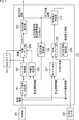
- FIG. 2is a diagram illustrating an internal configuration example of the self-position estimation unit 132.
- the self-position estimation unit 132includes a camera selection determination unit 201, a shutter control unit 202, a feature point estimation unit 203, a feature matching unit 204, a self-position estimation unit 205, a self-position holding unit 206, a motion prediction unit 207, and a feature matching unit 208. , An omnidirectional information holding unit 209, and a region weight determination unit 210.
- Control informationis supplied from the control unit 251 to the self-position estimation unit 132.
- the self-position estimation unit 132is also supplied with image data from a plurality of cameras.
- an omnidirectional camera 252 and a peripheral camera 253are mounted on the own vehicle.
- the control unit 251is, for example, a part that supplies information on the speed and moving direction of the own vehicle to the self-position estimation unit 132 and includes the vehicle state detection unit 143 and the situation recognition unit 153 in FIG.
- the omnidirectional camera 252 and the peripheral camera 253are cameras that capture the surroundings of the host vehicle, and include the data acquisition unit 102 and the outside information detection unit 141 in FIG.
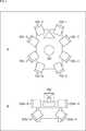
- FIG. 3is a diagram showing an example of arrangement positions of the omnidirectional camera 252 and the peripheral camera 253 mounted on the own vehicle.
- 3Ais a diagram schematically showing a position where the camera is arranged when the host vehicle is viewed from above
- FIG. 3Bis a diagram where the camera is arranged when the host vehicle is viewed from the rear. It is the figure which showed typically the position currently made. Note that the arrangement positions shown below are examples and do not indicate limitations.
- an omnidirectional camera 252is mounted near the center of the vehicle.
- the omnidirectional camera 252only needs to be installed at a position where a 360-degree peripheral region around the host vehicle can be photographed.
- the area of the surrounding environment photographed by the omnidirectional camera 252is an area of 360 degrees in a plane parallel to the ground (horizontal direction), and is an area within a predetermined range from the own vehicle.
- the area of the surrounding environment photographed by the omnidirectional camera 252may be 360 degrees on a plane orthogonal to the ground (vertical direction), but a predetermined range in the sky direction is an angle at which no photographing is performed, for example, 270 It is possible to make the region within a range of about degrees.
- the omnidirectional camera 252may be configured to be able to capture a 360-degree range with a single imaging device, or may be configured to be able to capture a 360-degree range with a plurality of imaging devices.
- peripheral cameras 253are mounted so that the surroundings of the vehicle can be photographed.
- FIG. 3Aan example in which eight peripheral cameras 253-1 to 253-8 are mounted is shown.
- the peripheral camera 253-1is disposed in front of the host vehicle, the peripheral camera 252-2 is disposed in front of the host vehicle, and the peripheral camera 253-3 is disposed in front of the host vehicle. 253-4 is arranged to the right of the host vehicle.
- the peripheral camera 253-5is disposed in front of the host vehicle, the peripheral camera 253-6 is disposed in front of the host vehicle, and the peripheral camera 253-7 is disposed in front of the host vehicle. 253-8 is located behind the left side of the vehicle.
- the peripheral camera 253includes a peripheral camera 253a-8 mounted in the horizontal direction and a peripheral camera 253b-8 mounted in the downward direction.
- FIG. 3Bis a view seen from the rear of the host vehicle, so that the peripheral camera 253-8 arranged behind the host vehicle can be seen.
- the peripheral camera 253 mounted in the horizontal directionis described as a horizontal camera 253a
- the peripheral camera 253 mounted in a downward directionis described as a downward camera 253b.
- the peripheral camera 253is simply described.
- the vehicleis equipped with eight horizontal cameras 253a-1 to 253a-8 and eight downward cameras 253b-1 to 253b-8.
- a set of the horizontal camera 253a-1 and the downward camera 253b-1constitutes a peripheral camera 253-1
- a set of the horizontal camera 253a-2 and the downward camera 253b-2constitutes a peripheral camera 253-2
- the horizontal camera A pair of 253a-3 and the downward camera 253b-3constitutes a peripheral camera 253-3
- a pair of the horizontal camera 253a-4 and the downward camera 253b-4constitutes a peripheral camera 253-4.
- the pair of the horizontal camera 253a-5 and the downward camera 253b-5constitutes the peripheral camera 253-5
- the pair of the horizontal camera 253a-6 and the downward camera 253b-6constitutes the peripheral camera 253-6
- a set of the camera 253a-7 and the downward camera 253b-7constitutes a peripheral camera 253-7
- a set of the horizontal camera 253a-8 and the downward camera 253b-8constitutes a peripheral camera 253-8.
- the host vehicleis equipped with the omnidirectional camera 252 that acquires a 360-degree peripheral image centered on the host vehicle and the plurality of peripheral cameras 253 that capture a predetermined area around the host vehicle. .
- peripheral cameras 253are not limited to sixteen, It may be the number.
- omnidirectional camera 252may be mounted.
- the camera selection determination unit 201is supplied with control information from the control unit 251 and weighted region information from the omnidirectional information holding unit 209.
- control informationit is the information regarding the advancing direction, speed, etc. of the own vehicle, for example.
- the weighted area informationwill be described in detail later, but when eight peripheral cameras 253 are mounted as shown in FIG. 3, information on the weights for the areas photographed by the eight peripheral cameras 253 respectively. It is.
- the camera selection determination unit 201selects a peripheral camera 253 to be used from among the 16 peripheral cameras 253 using the control information and the weighted area information.
- the peripheral camera to be used 253means that the selected peripheral camera 253 is turned on when used, and the peripheral cameras 253 other than the selected peripheral camera 253 are turned off when used.
- the selection determination result by the camera selection determination unit 201is supplied to the shutter control unit 202 and the feature point estimation unit 203.
- the shutter control unit 202controls the photographing process of the peripheral camera 253 selected by the camera selection determination unit 201.
- the feature matching unit 204is supplied with an image photographed by the peripheral camera 253, information on the peripheral camera 253 whose photographing processing is controlled by the shutter control unit 202, and an estimation result from the feature point estimation unit 203.
- the feature matching unit 204extracts a feature point from the image, searches for a feature point extracted from the image of the previous frame that matches the feature point, generates a corresponding pair of feature points, and sends it to the self-position estimation unit 205. Supply.
- feature pointsare extracted, but they may be regions instead of points.
- an edge portionmay be extracted from the image, a region having the edge may be extracted as a feature region, and used for subsequent processing.
- the process of sorting the areas according to the number of feature points in the predetermined areais executed. Even in this process, if the area is used, it is extracted as a characteristic area. Sort processing is executed according to the size of the area.
- the descriptionwill be continued by taking as an example a case where the feature point extracted from the image one frame before and the feature point extracted from the image of the current frame are compared, but not a frame before, but a few frames before
- the present technologycan also be applied when the current frame is compared with the current frame.
- the timing at which a frame (image) is acquiredmay be a general timing, for example, a timing such as 30 frames per second, but may be another timing.
- the self-position estimation unit 205estimates the position of the own vehicle using the corresponding pair of feature points.
- the estimation result from the self-position estimation unit 205includes the position of the vehicle, the posture of the vehicle, information on the surrounding environment (landmark information), and the like.
- the information on the self position and the self postureis output to the outside of the self position estimation unit 132, for example, the map analysis unit 151 and the situation recognition unit 153 (FIG. 1).
- Information such as the self position, self posture, and surrounding environmentis also supplied to and held in the self position holding unit 206.
- the self-position holding unit 206holds information on self-position, self-posture, surrounding environment, etc. for at least one frame. These pieces of information are necessary for creating the environment map.
- the environment mapis registered in advance on the three-dimensional coordinates corresponding to the real space, for example, SLAM (Simultaneous Localization AndappingMapping). This information is obtained by a method of estimating the self-position from the corresponding relationship between the landmarks and the sequentially registered landmarks and the feature points detected from the photographed image.
- a landmarkis a part of a subject in real space in which a feature point is detected from a captured image or a feature point can be detected from a captured image, and information indicating the position of each landmark when self-position estimation is performed. That is, a three-dimensional map indicating the landmark position information in the three-dimensional coordinate system is used.
- the processing in the feature matching unit 204the correspondence between the feature points detected from the captured images with different shooting times is obtained, the correspondence between the feature points, and the feature points and landmarks
- the self-position of the own vehicleis obtained by estimation from the correspondence relationship of the vehicle. Information regarding the estimated self-position is held in the self-position holding unit 206.
- the information on the surrounding environment held in the self-position holding unit 206is supplied to the feature point estimation unit 203.
- the feature point estimation unit 203predicts where the feature point of the previous frame was captured in the image captured by the peripheral camera 253 selected by the camera selection determination unit 201.
- the camera selection determination unit 201selects the peripheral camera 253-6, and the peripheral camera 253-6 performs shooting, and the image 301-1 is captured. To do. A feature point 311-1 is detected from this image 301-1.
- the camera selection determination unit 201selects the peripheral camera 253-7, and the peripheral camera 253-7 captures an image and the image 301-4 is captured. .
- a feature point 311-2is detected from this image 301-4. It is assumed that the feature point 311-1 and the feature point 311-2 are feature points extracted from the same stationary object.
- the feature matching unit 204extracts the feature point 311-1 extracted from the image 301-1 photographed at the time t-1 and the image 301-4 photographed at the time t0.
- the feature matching unit 204extracts the feature point 311-1 extracted from the image 301-1 photographed at the time t-1 and the image 301-4 photographed at the time t0.
- the feature point 311-1is in the center of the image 301-1, and the feature point 311-2 is in the center of the image 301-4, the feature point 311 is not moved in the image 301. Therefore, there is a possibility that self-position estimation that the vehicle is not moving is performed.
- the peripheral camera 253-7captures the image 301-1 ′ and the image 301-2 ′, and the feature point 311-1 ′ is extracted. Then, the feature point 311-1 ′ is matched with the feature point 311-2 extracted from the image 301-4 photographed by the peripheral camera 253-7 at time t0.
- the feature point estimation unit 203performs processing for estimating the position of the feature point extracted from the image one frame before in the image of the current frame. It is supplied to the matching unit 204.
- the feature matching unit 204performs matching in a state as shown in FIG.
- the feature point 311-1 'estimated as the position of the feature point at the time t-1is matched with the feature point 311-2 extracted as the feature point at the time t0.
- the self-position estimation unit 132is also supplied with an image captured by the omnidirectional camera 252.
- An image captured by the omnidirectional camera 252is supplied to the feature matching unit 208.
- the feature matching unit 208performs matching between feature points extracted from an image captured by the omnidirectional camera 252 and feature points supplied from the motion prediction unit 207.
- An image obtained by the omnidirectional camera 252is divided into eight.
- the image 351is divided into eight regions.
- the number of divisions of the image 351is the same as the number of peripheral cameras 253 (the number of sets). In other words, the number of divisions of the image 351 is the same as the number of horizontal cameras 253a.
- the number of horizontal cameras 253ais 8, the number of divisions of the image 351 is 8, and the image is divided into 8 regions.
- the image 351 captured by the omnidirectional camera 252is divided into the same number of regions as the number of horizontal cameras 253a.
- the horizontal camera 253a to be usedis selected depending on the number of feature points extracted from the region. It is for doing so.
- an area 351-1is an area assigned to the horizontal camera 253a-1, and when there are many feature points that are extracted from the area 351-1 and satisfy a predetermined condition, The horizontal camera 253a-1 is selected as the horizontal camera 253a to be used.
- the area 351-2is an area allocated to the horizontal camera 253a-2
- the area 351-3is an area allocated to the horizontal camera 253a-3
- the area 351-4is the horizontal camera 253a.
- -4is an area allocated.
- the area 351-5is an area allocated to the horizontal camera 253a-5
- the area 351-6is an area allocated to the horizontal camera 253a-6
- the area 351-7is the horizontal camera.
- the area 351-8is an area allocated to the horizontal camera 253a-8.
- the feature point 371-1is extracted from the region 351-2
- the feature point 371-2is extracted from the region 351-6
- the feature point 371-3is extracted from the region 351-7
- the feature point 371-4is extracted.
- Information on the feature point 371 extracted at time t ⁇ 1is held in the omnidirectional information holding unit 209 as surrounding environment information, and is supplied to the motion prediction unit 207 at time t0.
- Control informationis also supplied from the control unit 251 to the motion prediction unit 207.
- the control informationis information related to the traveling direction of the host vehicle, and here, the description will be continued with an example in which information indicating that the vehicle is traveling straight ahead is input.
- the motion prediction unit 207determines from the control information that the traveling direction of the host vehicle is forward, and the feature points 371-1 to 371-4 extracted at time t-1 are Predict which position you are moving to. When the host vehicle is moving forward, the stationary object moves relatively backward, so the feature point 371 is also expected to move backward (lower side in FIG. 5).
- the feature points 371-1 to 371-4are estimated to be feature points 371-1 'to 371-4' moved backward. At the time of this estimation, it is possible to perform the estimation more accurately by estimating the movement speed in consideration.
- the motion predicting unit 207when it is estimated that the feature point 371-4 ′ is located outside the image 351 ′, the motion predicting unit 207, as shown in the lower diagram of FIG.
- the feature points 371-1 to 371-3are output to the feature matching unit 208. That is, in this case, feature point information excluding the feature point 371-4 that is estimated not to be extracted from the image captured at time t 0 is supplied to the feature matching unit 208.
- the motion prediction unit 207narrows down the number of feature points used for matching, thereby reducing the processing of the feature matching unit 208.
- the feature matching unit 208receives information on the feature point 371 from the motion prediction unit 207 (information obtained from the image at time t ⁇ 1 as shown in the upper left diagram of FIG. 6) and the omnidirectional camera 252. Are matched (information obtained from the image at time t0 as shown in the upper right diagram in FIG. 6).
- the feature matching unit 208moves the feature point 371-1 extracted from the image 351 obtained from the omnidirectional camera 252 at time t-1 to the feature point 381-1, and the feature point 371-2 It moves to the feature point 381-2, and it is determined that the feature point 371-3 has moved to the feature point 381-3.
- the feature matching unit 204detects the moving direction of the feature point as a result of the matching of the feature points, and detects the feature point in which the moving direction of the feature point matches the moving direction of the host vehicle.
- the feature point 381-1is a feature point obtained by moving the feature point 371-1 upward
- the feature point 381-2is the feature point 371-2.
- the feature point 381-3is determined to be the feature point that has been moved downward.
- the feature point 381-4is determined to be a feature point that has not been matched with the feature point extracted from the image 351 taken at time t-1.
- the feature matching unit 208outputs such a matching result to the region weight determination unit 210.
- the area weight determination unit 210is supplied with information on the self position and the self posture from the self position estimation unit 205, and is supplied with a matching result from the feature matching unit 208.
- the area weight determination unit 210detects a feature point in a direction that matches the moving direction of the host vehicle. For example, when the own vehicle is moving forward, the feature point extracted from the stationary object moves backward, so it is determined that the feature point in the direction matching the moving direction of the own vehicle has moved backward. It becomes the feature point. Also, for example, when the own vehicle is moving backward, the feature point extracted from the stationary object moves forward, so that the feature point in the direction matching the moving direction of the own vehicle has moved forward The determined feature point.
- the area weight determination unit 210detects a feature point that is moving in a movement direction that matches (is not inconsistent with) the movement direction of the host vehicle. For example, the matching result as shown in the lower diagram of FIG. 6 is supplied to the area weight determination unit 210, and it is determined that the moving direction of the own vehicle is the front (the characteristic point is determined to move backward).
- the feature point 381-2 and the feature point 381-3are detected as feature points in a direction matching the moving direction of the host vehicle.
- the feature point 381-1is not a feature point in a direction that matches the moving direction of the host vehicle, it is not detected as a feature point in a direction that matches the moving direction of the host vehicle.
- a feature point that is moving in a direction that does not match the moving direction of the host vehicle, in other words, a moving direction that does not match the moving direction of the host vehicle, such as the feature point 381-1,is, for example, a feature extracted from a moving object. Is a point.
- the area weight determination unit 210detects feature points that match the moving direction of the host vehicle, detects the number of detected feature points for each area, and sorts the areas in descending order of the number of feature points.
- the region where many feature points are detectedis a region where information necessary for estimating the self-position, in this case, feature points extracted from a stationary object, can be easily extracted.
- the area weight determination unit 210sorts the areas in descending order of the number of feature points as described above. Then, the area is selected until the number of feature points in the sorted area reaches a predetermined number.
- the region 351-7 from which the feature point 381-2 is extracted and the region 351-8 from which the feature point 381-8 is extractedare detected.
- the number of feature points extracted from the regions 351-7 and 357-8is one, but for example, 20 feature points are extracted from the region 351-7, It is assumed that ten feature points are extracted from 351-8.
- the region 351-7 and the region 351-8are sorted in this order. If the predetermined number is 15, for example, the condition is satisfied when the region 351-7 is selected, so only the region 351-7 is selected. If the predetermined number is, for example, 30, for example, when the area 351-7 is selected, the condition is not yet satisfied, so the next area 351-8 is selected in the sorted order. When the region 351-8 is selected, the total number of feature points is 30, so the condition is satisfied, so the regions 351-7 and 351-8 are selected.
- the region weight determination unit 210thus selects the region 351 and supplies information on the selected region 351 to the omnidirectional information holding unit 209.
- the information output from the region weight determination unit 210is information on the selected region 351, but this information may be, for example, the number of feature points extracted from the region 351, or may be assigned according to the sorted order. It may be a numerical value.
- itmay be information such as a flag indicating where the selected area 351 is.
- the informationis flagged in the areas 351-7 and 351-8.
- the information on the selected area 351is supplied to the omnidirectional information holding unit 209 and held.
- the information of the selected area 351is information indicating an area where feature points extracted from a stationary object can be easily extracted. Such information is supplied to the camera selection determination unit 201 as weighted area information.
- the camera selection determination unit 201selects the peripheral camera 253 used for shooting as described above. For details, as will be described with reference to the flowchart shown in FIG. 7, whether to use the horizontal camera 253 a or the downward camera 253 b is selected according to the speed of the vehicle, and when the horizontal camera 253 a is used, The horizontal camera 253a to be used is selected based on the weighted area information. Specifically, the selected area 351 is determined based on the weighted area information, and the horizontal camera 253a corresponding to the determined area 351 is selected.
- the peripheral camera 253since the peripheral camera 253 is selected, in other words, since the peripheral camera 253 used for shooting and the peripheral camera 253 not used are selected, the power consumed by the peripheral camera 253 can be suppressed, The number of images to be processed can be reduced, and the processing load for image processing (self-position estimation processing) can be reduced.
- a case where a total of 16 peripheral cameras 253 including eight horizontal cameras 253a and eight downward cameras 253b are mountedis described as an example. .
- the power consumptionis lower.
- the power consumptionis lower when a predetermined number of horizontal cameras 253a are used.
- the peripheral camera 253 to be usedis selected depending on the speed and the number of feature points, the power consumption can be reduced and the processing load can be reduced without reducing the accuracy of self-position estimation. Can be reduced.
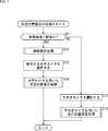
- step S11the camera selection determination unit 201 determines whether the moving speed of the host vehicle is equal to or greater than (greater than) a predetermined threshold value. If it is determined in step S11 that the moving speed of the own vehicle is equal to or higher than the predetermined threshold, the process proceeds to step S12, and if it is determined that the moving speed of the own vehicle is not equal to or higher than the predetermined threshold, step S15 is performed. The process proceeds.
- the peripheral camera 253 used for shootingis set as the horizontal camera 253a, and the self-position estimation process is performed.
- the peripheral camera 253 used for shootingis set as the downward camera 253b, and the self-position estimation process is performed.
- the moving speed of the own vehicleis equal to or higher than the predetermined threshold, in other words, when the own vehicle is moving at a high speed, the horizontal camera 253a is used, and the moving speed of the own vehicle is equal to or higher than the predetermined threshold. If not, in other words, when the vehicle is moving at a low speed, the downward camera 253b is used.
- the descriptionwill be made separately for high speed and low speed, but in other words, the description will be continued with an example in which there is one predetermined threshold value. good. For example, it is divided into high speed (above threshold A), medium speed (smaller than threshold A, over threshold B), and low speed (smaller than threshold B).
- high speedthe horizontal camera 253a is used.
- the horizontal camera 253a and the downward camera 253bmay be used, and in the case of low speed, the downward camera 253b may be used.
- step S11If it is determined in step S11 that the moving speed of the vehicle is faster than the threshold speed, the process proceeds to step S12. In step S12, an area selection process is executed. The area selection process executed in step S12 will be described with reference to the flowchart of FIG.
- the region selection processingis performed by the motion prediction unit 207, the feature matching unit 208, the omnidirectional information holding unit 209, and the region weight determination unit 210, and is performed as described with reference to FIGS. The description will be omitted as appropriate.
- step S31an image from the omnidirectional camera 252 is acquired.
- the image from the omnidirectional camera 252is supplied to the feature matching unit 208.
- step S ⁇ b> 32the feature matching unit 208 extracts feature points from the supplied image from the omnidirectional camera 252. While such processing is performed, in step S33, the feature point extracted from the image one frame before is read from the omnidirectional information holding unit 209.
- the motion prediction unit 207reads the feature points (peripheral environment information) extracted from the image one frame before from the omnidirectional information holding unit 209, and from the control information, Is determined, the destination of the feature point is predicted from the traveling direction of the host vehicle, and the prediction result is supplied to the feature matching unit 208.
- step S34as described with reference to FIG. 6, the feature matching unit 208 matches the feature point from the image one frame before and the feature point from the image of the current frame.
- step S35the moving direction of each feature point is determined as a result of matching.
- step S36feature points where the moving direction of the vehicle and the moving direction of the feature points match are extracted.
- feature points that are determined to have a valid moving direction (no contradiction) with respect to the traveling direction of the host vehicleare extracted.
- step S37the region weight determination unit 210 sorts the regions 351 in descending order of the number of feature points in each region 351.
- step S38the area 351 is selected in the sorted order until the cumulative number of feature points satisfies a predetermined number.
- the selection resultis supplied to the omnidirectional information holding unit 209, and the area weight information held in the omnidirectional information holding unit 209 is updated.
- step S13(FIG. 7).
- step S13the camera selection determination unit 201 selects the horizontal camera 253a to be used. If the camera selection determination unit 201 determines that the moving speed of the host vehicle is high, the camera selection determination unit 201 sets the peripheral camera 253 that captures an image used for self-position estimation to the horizontal camera 253a, and further sets the omnidirectional information storage unit 209. Of the eight horizontal cameras 253a, which horizontal camera 253a is used is set from the weighted area information held.
- the horizontal camera 253a corresponding to the weighted area 351is set as the horizontal camera 253a to be used (the horizontal camera 253a that turns on the power and executes the photographing process).
- the weighted area informationis information related to the area 351 selected by the area weight determination unit 210 as an area from which more feature points that can be used for self-position estimation can be extracted. Therefore, by using the horizontal camera 253a that captures the range of such a region 351, an image in which a region where feature points used for self-position estimation are easily extracted can be obtained.
- step S14a self-position estimation process using the horizontal camera 253a is executed.
- the self-position estimation process executed in step S14will be described with reference to the flowchart shown in FIG.
- step S51the shutter control unit 202 controls the selected horizontal camera 253a to capture an image.
- the captured imageis supplied to the feature matching unit 204.
- power consumption for shootingcan be reduced.
- the image from the selected horizontal camera 253ais processed, for example, processing such as feature point extraction is performed, the number of images to be processed can be reduced, and the processing load can be reduced.
- step S52the feature matching unit 204 extracts feature points.
- step S ⁇ b> 53the feature point estimation unit 203 reads the surrounding environment information held in the self-position holding unit 206. This surrounding environment information includes information on feature points extracted from the image one frame before.
- step S54the feature point estimation unit 203 estimates in which position the feature point extracted from the image one frame before is located on the image captured by the selected horizontal camera 253a.
- the processing executed by the feature point estimation unit 203 in step S53 and step S54is where the feature point extracted from the image one frame before is located in the image of the current frame. This is a process of estimating (converting) whether or not
- step S55the feature matching unit 204 detects a corresponding pair by performing block matching between the feature point extracted from the image of the previous frame and the feature point extracted from the image of the current frame.
- the image photographed by the horizontal camera 253ais a scenery around the own vehicle, such as a building, a tree, a guardrail, and the like. Since block matching is suitable for such a landscape image matching process, the description will be continued here assuming that the matching process is performed by block matching.
- a matching method other than block matchingcan be used as a matching process using an image photographed by the horizontal camera 253a.
- feature pointsare extracted and matching processing is executed, but information suitable for matching processing using an image photographed by the horizontal camera 253a is extracted.
- the application range of the present technologyis also applicable to a case where an area having a feature is extracted instead of a point.
- step S56the self position estimating unit 205 estimates the self position. Any method of self-positioning can be applied to the present technology.
- DLTDirect Linear Transform
- PNPPerspective
- the feature matching unit 204is configured to perform matching by a matching method suitable for the method used by the self-position estimating unit 205 and output a matching result.
- the horizontal camera 253acaptures an image, and self-position estimation is performed using the captured image. Further, matching is performed using a matching method suitable for an image photographed by the horizontal camera 253a.
- step S11If it is determined in step S11 that the moving speed of the host vehicle is not equal to or higher than the threshold, in other words, if it is determined that the moving speed is low, the process proceeds to step S15.
- step S15the downward camera 253b is selected as the camera to be used.
- the downward camera 253ball the downward cameras 253b installed, in this case, eight downward cameras 253b are used. Since the downward camera 253b is mounted downward with respect to the own vehicle, the camera 253b mainly shoots the road surface.
- the downward camera 253bcorresponding to the region where it is determined that feature points are easily extracted using the weighted information held in the omnidirectional information holding unit 209, It is also possible to set as the downward camera 253b to be used.
- the downward camera 253b mounted on the moving direction sidecan be selected according to the moving direction of the own vehicle. For example, when the host vehicle is moving forward, the downward cameras 253b-1, 253b-2, 253b-5, and 253b-6 arranged in front are used, and when moving backward, The arranged downward cameras 253b-3, 253b-4, 253b-7, and 253b-8 may be used.
- step S16a self-position estimation process using the downward camera 253b is executed.
- the self-position estimation process using the downward camera 253b executed in step S16will be described with reference to the flowchart shown in FIG.
- the self-position estimation process using the downward camera 253b shown in FIG. 10is the same as the self-position estimation process using the horizontal camera 253a shown in FIG.
- step S71the shutter control unit 202 controls the selected downward camera 253b, in this case, eight downward cameras 253b, and images are taken.
- the captured imageis supplied to the feature matching unit 204.
- step S72the feature matching unit 204 extracts feature points.
- the feature pointmay be a pattern of light brightness on the road surface.
- the feature point estimation unit 203reads the surrounding environment information held in the self-position holding unit 206.
- This surrounding environment informationincludes information on feature points extracted from the image one frame before.
- the feature point estimation unit 203estimates at which position the feature point extracted from the image one frame before is located on the image captured by the selected downward camera 253b.
- the processing executed by the feature point estimation unit 203 in step S73 and step S74is where the feature point extracted from the image one frame before is located in the image of the current frame. This is a process of estimating (converting) whether or not
- the feature pointscan be obtained by processing the images of the eight downward cameras 253 b. Corresponding pairs may be obtained in the same manner as obtaining the moving direction of.
- step S ⁇ b> 75the feature matching unit 204 detects the corresponding pair by matching the feature point extracted from the image of the previous frame and the feature point extracted from the image of the current frame by the luminance gradient method. .
- a luminance patternis extracted from an image photographed by the downward camera 253b. Since the matching by the luminance gradient method is suitable for the matching process using the luminance pattern, here, the matching by the luminance gradient method is used. The description will be continued assuming that processing is performed.
- a matching method other than the luminance gradient methodcan be used as a matching process using an image photographed by the downward camera 253b.
- the luminance pattern (feature point)is extracted and the matching process is executed, but information suitable for the matching process using the image photographed by the downward camera 253b is extracted.
- the application range of the present technologyis also applicable to a case where an area having a feature is extracted instead of a point.
- step S76the self-position estimating unit 205 estimates the self-position. Any method of self-positioning can be applied to the present technology.
- the self-position estimation algorithm(matching method in the feature matching unit 204) when the horizontal camera 253a is selected and the self-position estimation algorithm (in the feature matching unit 204) when the downward camera 253b is selected.
- the matching methodis a different algorithm, and is configured such that an algorithm suitable for a captured image is applied. Therefore, self-position estimation can be performed with higher accuracy.
- the accuracy of self-position estimationdoes not decrease, and accurate self-position estimation can be performed.
- the present inventionis applied to a passenger car (automobile) has been described as an example. It can be applied to a moving body such as a robot.
- the above-described series of processingcan be executed by hardware or can be executed by software.
- a program constituting the softwareis installed in the computer.
- the computerincludes, for example, a general-purpose personal computer capable of executing various functions by installing a computer incorporated in dedicated hardware and various programs.
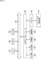
- FIG. 11is a block diagram showing an example of a hardware configuration of a computer that executes the above-described series of processing by a program.
- a CPUCentral Processing Unit
- ROMRead Only Memory
- RAMRandom Access Memory
- An input / output interface 505is further connected to the bus 504.
- An input unit 506, an output unit 507, a recording unit 508, a communication unit 509, and a drive 510are connected to the input / output interface 505.
- the input unit 506includes an input switch, a button, a microphone, an image sensor, and the like.
- the output unit 507includes a display, a speaker, and the like.
- the recording unit 508includes a hard disk, a nonvolatile memory, and the like.
- the communication unit 509includes a network interface or the like.
- the drive 510drives a removable recording medium 511 such as a magnetic disk, an optical disk, a magneto-optical disk, or a semiconductor memory.
- the CPU 501loads the program recorded in the recording unit 508 to the RAM 503 via the input / output interface 505 and the bus 504 and executes the program, for example. Is performed.
- the program executed by the computer (CPU 501)can be provided by being recorded in a removable recording medium 511 as a package medium, for example.
- the programcan be provided via a wired or wireless transmission medium such as a local area network, the Internet, or digital satellite broadcasting.
- the programcan be installed in the recording unit 508 via the input / output interface 505 by attaching the removable recording medium 511 to the drive 510. Further, the program can be received by the communication unit 509 via a wired or wireless transmission medium and installed in the recording unit 508. In addition, the program can be installed in the ROM 502 or the recording unit 508 in advance.
- the program executed by the computermay be a program that is processed in time series in the order described in this specification, or in parallel or at a necessary timing such as when a call is made. It may be a program for processing.
- the present technologycan take a cloud computing configuration in which one function is shared by a plurality of devices via a network and is jointly processed.
- each step described in the above flowchartcan be executed by one device or can be shared by a plurality of devices.
- the plurality of processes included in the one stepcan be executed by being shared by a plurality of apparatuses in addition to being executed by one apparatus.
- a selection unitthat selects a camera to be used for self-position estimation among a horizontal camera mounted in a horizontal direction and a downward camera mounted in a downward direction according to speed
- a control apparatuscomprising: a self-position estimation unit that performs self-position estimation using an image obtained by photographing with the horizontal camera or the downward camera selected by the selection unit.
- the setting unitdivides an image captured by the omnidirectional camera by the number of the horizontal cameras, and the direction in which the feature points extracted from the divided images have moved over time, and self-position estimation
- the control deviceaccording to (3), wherein the horizontal camera that captures an area having a large number of feature points to which the moving direction of the self based on the estimation result of is selected.
- the first algorithm for self-position estimation when the horizontal camera is selected by the selection unit and the second algorithm for self-position estimation when the downward camera is selected by the selection unitare different algorithms.
- the control deviceaccording to any one of (1) to (4).
- the control deviceaccording to (5), wherein the first algorithm is block matching, and the second algorithm is a luminance gradient method. (7) (1) to (1) to estimate a position corresponding to the position of the feature point extracted from the image captured by the horizontal camera at a time before the current time when the current horizontal camera is selected.
- the control deviceaccording to any one of (6).
- vehicle control system101 input unit, 102 data acquisition unit, 103 communication unit, 104 in-vehicle equipment, 105 output control unit, 106 output unit, 107 drive system control unit, 108 drive system system, 109 body system control unit, 110 body System, 111 storage unit, 112 automatic operation control unit, 121 communication network, 131 detection unit, 132 self-position estimation unit, 133 situation analysis unit, 134 planning unit, 135 operation control unit, 141 outside information detection unit, 142 in-vehicle information Detection unit, 143 vehicle state detection unit, 151 map analysis unit, 152 traffic rule recognition unit, 153 situation recognition unit, 154 situation prediction unit, 161 route plan unit, 162 action plan unit, 163 motion meter Part, 171 emergency situation avoidance part, 172 acceleration / deceleration control part, 173 direction control part, 201 camera selection determination part, 202 shutter control part, 203 feature point estimation part, 204 feature matching part, 205 self-position estimation part, 206 self-position Holding unit, 201
Landscapes
- Engineering & Computer Science (AREA)
- Physics & Mathematics (AREA)
- Computer Vision & Pattern Recognition (AREA)
- General Physics & Mathematics (AREA)
- Remote Sensing (AREA)
- Radar, Positioning & Navigation (AREA)
- Theoretical Computer Science (AREA)
- Multimedia (AREA)
- Aviation & Aerospace Engineering (AREA)
- Automation & Control Theory (AREA)
- Electromagnetism (AREA)
- Traffic Control Systems (AREA)
- Navigation (AREA)
- Control Of Position, Course, Altitude, Or Attitude Of Moving Bodies (AREA)
Abstract
Description
Translated fromJapanese本技術は制御装置、制御方法、並びにプログラムに関し、例えば、自己位置推定を精度良く、低消費電力で行えるようにした制御装置、制御方法、並びにプログラムに関する。The present technology relates to a control device, a control method, and a program. For example, the present technology relates to a control device, a control method, and a program that can perform self-position estimation with high accuracy and low power consumption.
従来、カメラで撮影された画像に基づいて、実空間上におけるカメラの位置を推定する自己位置推定では、画像に含まれている指標となる勾配や特徴点などが用いられて、カメラの自己位置が推定される(例えば、特許文献1参照)。また複数のカメラを用いることで、カメラにより観察されない領域、所謂死角を減らすことができるので、画像から特徴点が検出されないような状況を回避することも提案されている。Conventionally, in the self-position estimation in which the position of the camera in the real space is estimated based on the image taken by the camera, a gradient or a feature point that is an index included in the image is used, and the self-position of the camera Is estimated (see, for example, Patent Document 1). In addition, by using a plurality of cameras, an area that is not observed by the cameras, so-called blind spots, can be reduced, and it has been proposed to avoid a situation in which feature points are not detected from an image.
しかしながら、常に複数のカメラで周囲の環境を撮影すると、自己位置推定に用いるカメラの数が増える分だけ、電力消費量が増加する。特に、カメラの数に対して電力消費量は正比例することから、自己位置推定での消費電力を低く抑えるのが望まれている。However, if the surrounding environment is always photographed with a plurality of cameras, the power consumption increases as the number of cameras used for self-position estimation increases. In particular, since power consumption is directly proportional to the number of cameras, it is desired to reduce power consumption in self-position estimation.
本技術は、このような状況に鑑みてなされたものであり、より低い消費電力で確実に自己位置を推定することができるようにするものである。The present technology has been made in view of such a situation, and enables the self-position to be reliably estimated with lower power consumption.
本技術の一側面の制御装置は、水平方向に装着された水平カメラと下向き方向に装着された下向きカメラのうち、自己位置推定に用いるカメラを速度により選択する選択部と、前記選択部により選択された前記水平カメラまたは前記下向きカメラによる撮影で得られた画像を用いて自己位置推定を行う自己位置推定部とを備える。A control device according to an aspect of the present technology includes: a selection unit that selects a camera used for self-position estimation among a horizontal camera mounted in a horizontal direction and a downward camera mounted in a downward direction, and the selection unit selects the camera A self-position estimating unit that performs self-position estimation using an image obtained by photographing with the horizontal camera or the downward camera.
本技術の一側面の制御方法は、制御装置が、水平方向に装着された水平カメラと下向き方向に装着された下向きカメラのうち、自己位置推定に用いるカメラを速度により選択処理し、前記選択部により選択された前記水平カメラまたは前記下向きカメラによる撮影で得られた画像を用いて自己位置推定処理を行う。In the control method according to one aspect of the present technology, the control device selects a camera used for self-position estimation based on a speed from a horizontal camera mounted in a horizontal direction and a downward camera mounted in a downward direction, and the selection unit The self-position estimation process is performed using an image obtained by photographing with the horizontal camera or the downward camera selected by the above.
本技術の一側面のプログラムは、コンピュータに、水平方向に装着された水平カメラと下向き方向に装着された下向きカメラのうち、自己位置推定に用いるカメラを速度により選択し、前記選択部により選択された前記水平カメラまたは前記下向きカメラによる撮影で得られた画像を用いて自己位置推定を行う処理を実行させる。A program according to an aspect of the present technology selects a camera to be used for self-position estimation from a horizontal camera mounted in a horizontal direction and a downward camera mounted in a downward direction on a computer, and is selected by the selection unit. In addition, a process for performing self-position estimation using an image obtained by photographing with the horizontal camera or the downward camera is executed.
本技術の一側面の制御装置、制御方法、並びにプログラムにおいては、水平方向に装着された水平カメラと下向き方向に装着された下向きカメラのうち、自己位置推定に用いるカメラが速度により選択され、選択された水平カメラまたは下向きカメラによる撮影で得られた画像を用いられて自己位置推定が行われる。In the control device, the control method, and the program according to one aspect of the present technology, the camera used for self-position estimation is selected and selected from the horizontal camera mounted in the horizontal direction and the downward camera mounted in the downward direction. Self-position estimation is performed using an image obtained by photographing with the horizontal camera or the downward camera.
なお、制御装置は、独立した装置であっても良いし、1つの装置を構成している内部ブロックであっても良い。The control device may be an independent device or may be an internal block constituting one device.
また、プログラムは、伝送媒体を介して伝送することにより、または、記録媒体に記録して、提供することができる。Also, the program can be provided by being transmitted through a transmission medium or by being recorded on a recording medium.
本技術の一側面によれば、より低い消費電力で確実に自己位置を推定することができる。According to one aspect of the present technology, the self-position can be reliably estimated with lower power consumption.
なお、ここに記載された効果は必ずしも限定されるものではなく、本開示中に記載されたいずれかの効果であってもよい。It should be noted that the effects described here are not necessarily limited, and may be any of the effects described in the present disclosure.
以下に、本技術を実施するための形態(以下、実施の形態という)について説明する。Hereinafter, modes for carrying out the present technology (hereinafter referred to as embodiments) will be described.
図1は、本技術が適用され得る移動体制御システムの一例である車両制御システム100の概略的な機能の構成例を示すブロック図である。FIG. 1 is a block diagram illustrating a schematic functional configuration example of a
車両制御システム100は、車両10に設けられ、車両10の各種の制御を行うシステムである。なお、以下、車両10を他の車両と区別する場合、自車又は自車両と称する。The
車両制御システム100は、入力部101、データ取得部102、通信部103、車内機器104、出力制御部105、出力部106、駆動系制御部107、駆動系システム108、ボディ系制御部109、ボディ系システム110、記憶部111、及び、自動運転制御部112を備える。入力部101、データ取得部102、通信部103、出力制御部105、駆動系制御部107、ボディ系制御部109、記憶部111、及び、自動運転制御部112は、通信ネットワーク121を介して、相互に接続されている。通信ネットワーク121は、例えば、CAN(Controller Area Network)、LIN(Local Interconnect Network)、LAN(Local Area Network)、又は、FlexRay(登録商標)等の任意の規格に準拠した車載通信ネットワークやバス等からなる。なお、車両制御システム100の各部は、通信ネットワーク121を介さずに、直接接続される場合もある。The
なお、以下、車両制御システム100の各部が、通信ネットワーク121を介して通信を行う場合、通信ネットワーク121の記載を省略するものとする。例えば、入力部101と自動運転制御部112が、通信ネットワーク121を介して通信を行う場合、単に入力部101と自動運転制御部112が通信を行うと記載する。In the following, when each unit of the
入力部101は、搭乗者が各種のデータや指示等の入力に用いる装置を備える。例えば、入力部101は、タッチパネル、ボタン、マイクロフォン、スイッチ、及び、レバー等の操作デバイス、並びに、音声やジェスチャ等により手動操作以外の方法で入力可能な操作デバイス等を備える。また、例えば、入力部101は、赤外線若しくはその他の電波を利用したリモートコントロール装置、又は、車両制御システム100の操作に対応したモバイル機器若しくはウェアラブル機器等の外部接続機器であってもよい。入力部101は、搭乗者により入力されたデータや指示等に基づいて入力信号を生成し、車両制御システム100の各部に供給する。The
データ取得部102は、車両制御システム100の処理に用いるデータを取得する各種のセンサ等を備え、取得したデータを、車両制御システム100の各部に供給する。The
例えば、データ取得部102は、車両10の状態等を検出するための各種のセンサを備える。具体的には、例えば、データ取得部102は、ジャイロセンサ、加速度センサ、慣性計測装置(IMU)、及び、アクセルペダルの操作量、ブレーキペダルの操作量、ステアリングホイールの操舵角、エンジン回転数、モータ回転数、若しくは、車輪の回転速度等を検出するためのセンサ等を備える。For example, the
また、例えば、データ取得部102は、車両10の外部の情報を検出するための各種のセンサを備える。具体的には、例えば、データ取得部102は、ToF(Time Of Flight)カメラ、ステレオカメラ、単眼カメラ、赤外線カメラ、及び、その他のカメラ等の撮像装置を備える。また、例えば、データ取得部102は、天候又は気象等を検出するための環境センサ、及び、車両10の周囲の物体を検出するための周囲情報検出センサを備える。環境センサは、例えば、雨滴センサ、霧センサ、日照センサ、雪センサ等からなる。周囲情報検出センサは、例えば、超音波センサ、レーダ、LiDAR(Light Detection and Ranging、Laser Imaging Detection and Ranging)、ソナー等からなる。For example, the
さらに、例えば、データ取得部102は、車両10の現在位置を検出するための各種のセンサを備える。具体的には、例えば、データ取得部102は、GNSS(Global Navigation Satellite System)衛星からのGNSS信号を受信するGNSS受信機等を備える。Further, for example, the
また、例えば、データ取得部102は、車内の情報を検出するための各種のセンサを備える。具体的には、例えば、データ取得部102は、運転者を撮像する撮像装置、運転者の生体情報を検出する生体センサ、及び、車室内の音声を集音するマイクロフォン等を備える。生体センサは、例えば、座面又はステアリングホイール等に設けられ、座席に座っている搭乗者又はステアリングホイールを握っている運転者の生体情報を検出する。For example, the
通信部103は、車内機器104、並びに、車外の様々な機器、サーバ、基地局等と通信を行い、車両制御システム100の各部から供給されるデータを送信したり、受信したデータを車両制御システム100の各部に供給したりする。なお、通信部103がサポートする通信プロトコルは、特に限定されるものではなく、また、通信部103が、複数の種類の通信プロトコルをサポートすることも可能である。The
例えば、通信部103は、無線LAN、Bluetooth(登録商標)、NFC(Near Field Communication)、又は、WUSB(Wireless USB)等により、車内機器104と無線通信を行う。また、例えば、通信部103は、図示しない接続端子(及び、必要であればケーブル)を介して、USB(Universal Serial Bus)、HDMI(登録商標)(High-Definition Multimedia Interface)、又は、MHL(Mobile High-definition Link)等により、車内機器104と有線通信を行う。For example, the
さらに、例えば、通信部103は、基地局又はアクセスポイントを介して、外部ネットワーク(例えば、インターネット、クラウドネットワーク又は事業者固有のネットワーク)上に存在する機器(例えば、アプリケーションサーバ又は制御サーバ)との通信を行う。また、例えば、通信部103は、P2P(Peer To Peer)技術を用いて、車両10の近傍に存在する端末(例えば、歩行者若しくは店舗の端末、又は、MTC(Machine Type Communication)端末)との通信を行う。さらに、例えば、通信部103は、車車間(Vehicle to Vehicle)通信、路車間(Vehicle to Infrastructure)通信、車両10と家との間(Vehicle to Home)の通信、及び、歩車間(Vehicle to Pedestrian)通信等のV2X通信を行う。また、例えば、通信部103は、ビーコン受信部を備え、道路上に設置された無線局等から発信される電波あるいは電磁波を受信し、現在位置、渋滞、通行規制又は所要時間等の情報を取得する。Furthermore, for example, the
車内機器104は、例えば、搭乗者が有するモバイル機器若しくはウェアラブル機器、車両10に搬入され若しくは取り付けられる情報機器、及び、任意の目的地までの経路探索を行うナビゲーション装置等を含む。The in-
出力制御部105は、車両10の搭乗者又は車外に対する各種の情報の出力を制御する。例えば、出力制御部105は、視覚情報(例えば、画像データ)及び聴覚情報(例えば、音声データ)のうちの少なくとも1つを含む出力信号を生成し、出力部106に供給することにより、出力部106からの視覚情報及び聴覚情報の出力を制御する。具体的には、例えば、出力制御部105は、データ取得部102の異なる撮像装置により撮像された画像データを合成して、俯瞰画像又はパノラマ画像等を生成し、生成した画像を含む出力信号を出力部106に供給する。また、例えば、出力制御部105は、衝突、接触、危険地帯への進入等の危険に対する警告音又は警告メッセージ等を含む音声データを生成し、生成した音声データを含む出力信号を出力部106に供給する。The
出力部106は、車両10の搭乗者又は車外に対して、視覚情報又は聴覚情報を出力することが可能な装置を備える。例えば、出力部106は、表示装置、インストルメントパネル、オーディオスピーカ、ヘッドホン、搭乗者が装着する眼鏡型ディスプレイ等のウェアラブルデバイス、プロジェクタ、ランプ等を備える。出力部106が備える表示装置は、通常のディスプレイを有する装置以外にも、例えば、ヘッドアップディスプレイ、透過型ディスプレイ、AR(Augmented Reality)表示機能を有する装置等の運転者の視野内に視覚情報を表示する装置であってもよい。The
駆動系制御部107は、各種の制御信号を生成し、駆動系システム108に供給することにより、駆動系システム108の制御を行う。また、駆動系制御部107は、必要に応じて、駆動系システム108以外の各部に制御信号を供給し、駆動系システム108の制御状態の通知等を行う。The drive
駆動系システム108は、車両10の駆動系に関わる各種の装置を備える。例えば、駆動系システム108は、内燃機関又は駆動用モータ等の駆動力を発生させるための駆動力発生装置、駆動力を車輪に伝達するための駆動力伝達機構、舵角を調節するステアリング機構、制動力を発生させる制動装置、ABS(Antilock Brake System)、ESC(Electronic Stability Control)、並びに、電動パワーステアリング装置等を備える。The
ボディ系制御部109は、各種の制御信号を生成し、ボディ系システム110に供給することにより、ボディ系システム110の制御を行う。また、ボディ系制御部109は、必要に応じて、ボディ系システム110以外の各部に制御信号を供給し、ボディ系システム110の制御状態の通知等を行う。The body
ボディ系システム110は、車体に装備されたボディ系の各種の装置を備える。例えば、ボディ系システム110は、キーレスエントリシステム、スマートキーシステム、パワーウィンドウ装置、パワーシート、ステアリングホイール、空調装置、及び、各種ランプ(例えば、ヘッドランプ、バックランプ、ブレーキランプ、ウィンカ、フォグランプ等)等を備える。The
記憶部111は、例えば、ROM(Read Only Memory)、RAM(Random Access Memory)、HDD(Hard Disc Drive)等の磁気記憶デバイス、半導体記憶デバイス、光記憶デバイス、及び、光磁気記憶デバイス等を備える。記憶部111は、車両制御システム100の各部が用いる各種プログラムやデータ等を記憶する。例えば、記憶部111は、ダイナミックマップ等の3次元の高精度地図、高精度地図より精度が低く、広いエリアをカバーするグローバルマップ、及び、車両10の周囲の情報を含むローカルマップ等の地図データを記憶する。The
自動運転制御部112は、自律走行又は運転支援等の自動運転に関する制御を行う。具体的には、例えば、自動運転制御部112は、車両10の衝突回避あるいは衝撃緩和、車間距離に基づく追従走行、車速維持走行、車両10の衝突警告、又は、車両10のレーン逸脱警告等を含むADAS(Advanced Driver Assistance System)の機能実現を目的とした協調制御を行う。また、例えば、自動運転制御部112は、運転者の操作に拠らずに自律的に走行する自動運転等を目的とした協調制御を行う。自動運転制御部112は、検出部131、自己位置推定部132、状況分析部133、計画部134、及び、動作制御部135を備える。The automatic
検出部131は、自動運転の制御に必要な各種の情報の検出を行う。検出部131は、車外情報検出部141、車内情報検出部142、及び、車両状態検出部143を備える。The
車外情報検出部141は、車両制御システム100の各部からのデータ又は信号に基づいて、車両10の外部の情報の検出処理を行う。例えば、車外情報検出部141は、車両10の周囲の物体の検出処理、認識処理、及び、追跡処理、並びに、物体までの距離の検出処理を行う。検出対象となる物体には、例えば、車両、人、障害物、構造物、道路、信号機、交通標識、道路標示等が含まれる。また、例えば、車外情報検出部141は、車両10の周囲の環境の検出処理を行う。検出対象となる周囲の環境には、例えば、天候、気温、湿度、明るさ、及び、路面の状態等が含まれる。車外情報検出部141は、検出処理の結果を示すデータを自己位置推定部132、状況分析部133のマップ解析部151、交通ルール認識部152、及び、状況認識部153、並びに、動作制御部135の緊急事態回避部171等に供給する。The outside
車内情報検出部142は、車両制御システム100の各部からのデータ又は信号に基づいて、車内の情報の検出処理を行う。例えば、車内情報検出部142は、運転者の認証処理及び認識処理、運転者の状態の検出処理、搭乗者の検出処理、及び、車内の環境の検出処理等を行う。検出対象となる運転者の状態には、例えば、体調、覚醒度、集中度、疲労度、視線方向等が含まれる。検出対象となる車内の環境には、例えば、気温、湿度、明るさ、臭い等が含まれる。車内情報検出部142は、検出処理の結果を示すデータを状況分析部133の状況認識部153、及び、動作制御部135の緊急事態回避部171等に供給する。The in-vehicle
車両状態検出部143は、車両制御システム100の各部からのデータ又は信号に基づいて、車両10の状態の検出処理を行う。検出対象となる車両10の状態には、例えば、速度、加速度、舵角、異常の有無及び内容、運転操作の状態、パワーシートの位置及び傾き、ドアロックの状態、並びに、その他の車載機器の状態等が含まれる。車両状態検出部143は、検出処理の結果を示すデータを状況分析部133の状況認識部153、及び、動作制御部135の緊急事態回避部171等に供給する。The vehicle
自己位置推定部132は、車外情報検出部141、及び、状況分析部133の状況認識部153等の車両制御システム100の各部からのデータ又は信号に基づいて、車両10の位置及び姿勢等の推定処理を行う。また、自己位置推定部132は、必要に応じて、自己位置の推定に用いるローカルマップ(以下、自己位置推定用マップと称する)を生成する。自己位置推定用マップは、例えば、SLAM(Simultaneous Localization and Mapping)等の技術を用いた高精度なマップとされる。自己位置推定部132は、推定処理の結果を示すデータを状況分析部133のマップ解析部151、交通ルール認識部152、及び、状況認識部153等に供給する。また、自己位置推定部132は、自己位置推定用マップを記憶部111に記憶させる。The self-
状況分析部133は、車両10及び周囲の状況の分析処理を行う。状況分析部133は、マップ解析部151、交通ルール認識部152、状況認識部153、及び、状況予測部154を備える。The
マップ解析部151は、自己位置推定部132及び車外情報検出部141等の車両制御システム100の各部からのデータ又は信号を必要に応じて用いながら、記憶部111に記憶されている各種のマップの解析処理を行い、自動運転の処理に必要な情報を含むマップを構築する。マップ解析部151は、構築したマップを、交通ルール認識部152、状況認識部153、状況予測部154、並びに、計画部134のルート計画部161、行動計画部162、及び、動作計画部163等に供給する。The
交通ルール認識部152は、自己位置推定部132、車外情報検出部141、及び、マップ解析部151等の車両制御システム100の各部からのデータ又は信号に基づいて、車両10の周囲の交通ルールの認識処理を行う。この認識処理により、例えば、車両10の周囲の信号の位置及び状態、車両10の周囲の交通規制の内容、並びに、走行可能な車線等が認識される。交通ルール認識部152は、認識処理の結果を示すデータを状況予測部154等に供給する。The traffic
状況認識部153は、自己位置推定部132、車外情報検出部141、車内情報検出部142、車両状態検出部143、及び、マップ解析部151等の車両制御システム100の各部からのデータ又は信号に基づいて、車両10に関する状況の認識処理を行う。例えば、状況認識部153は、車両10の状況、車両10の周囲の状況、及び、車両10の運転者の状況等の認識処理を行う。また、状況認識部153は、必要に応じて、車両10の周囲の状況の認識に用いるローカルマップ(以下、状況認識用マップと称する)を生成する。状況認識用マップは、例えば、占有格子地図(Occupancy Grid Map)とされる。The
認識対象となる車両10の状況には、例えば、車両10の位置、姿勢、動き(例えば、速度、加速度、移動方向等)、並びに、異常の有無及び内容等が含まれる。認識対象となる車両10の周囲の状況には、例えば、周囲の静止物体の種類及び位置、周囲の動物体の種類、位置及び動き(例えば、速度、加速度、移動方向等)、周囲の道路の構成及び路面の状態、並びに、周囲の天候、気温、湿度、及び、明るさ等が含まれる。認識対象となる運転者の状態には、例えば、体調、覚醒度、集中度、疲労度、視線の動き、並びに、運転操作等が含まれる。The situation of the
状況認識部153は、認識処理の結果を示すデータ(必要に応じて、状況認識用マップを含む)を自己位置推定部132及び状況予測部154等に供給する。また、状況認識部153は、状況認識用マップを記憶部111に記憶させる。The
状況予測部154は、マップ解析部151、交通ルール認識部152及び状況認識部153等の車両制御システム100の各部からのデータ又は信号に基づいて、車両10に関する状況の予測処理を行う。例えば、状況予測部154は、車両10の状況、車両10の周囲の状況、及び、運転者の状況等の予測処理を行う。The
予測対象となる車両10の状況には、例えば、車両10の挙動、異常の発生、及び、走行可能距離等が含まれる。予測対象となる車両10の周囲の状況には、例えば、車両10の周囲の動物体の挙動、信号の状態の変化、及び、天候等の環境の変化等が含まれる。予測対象となる運転者の状況には、例えば、運転者の挙動及び体調等が含まれる。The situation of the
状況予測部154は、予測処理の結果を示すデータを、交通ルール認識部152及び状況認識部153からのデータとともに、計画部134のルート計画部161、行動計画部162、及び、動作計画部163等に供給する。The
ルート計画部161は、マップ解析部151及び状況予測部154等の車両制御システム100の各部からのデータ又は信号に基づいて、目的地までのルートを計画する。例えば、ルート計画部161は、グローバルマップに基づいて、現在位置から指定された目的地までのルートを設定する。また、例えば、ルート計画部161は、渋滞、事故、通行規制、工事等の状況、及び、運転者の体調等に基づいて、適宜ルートを変更する。ルート計画部161は、計画したルートを示すデータを行動計画部162等に供給する。The
行動計画部162は、マップ解析部151及び状況予測部154等の車両制御システム100の各部からのデータ又は信号に基づいて、ルート計画部161により計画されたルートを計画された時間内で安全に走行するための車両10の行動を計画する。例えば、行動計画部162は、発進、停止、進行方向(例えば、前進、後退、左折、右折、方向転換等)、走行中車線、走行速度、及び、追い越し等の計画を行う。行動計画部162は、計画した車両10の行動を示すデータを動作計画部163等に供給する。Based on data or signals from each part of the
動作計画部163は、マップ解析部151及び状況予測部154等の車両制御システム100の各部からのデータ又は信号に基づいて、行動計画部162により計画された行動を実現するための車両10の動作を計画する。例えば、動作計画部163は、加速、減速、及び、走行軌道等の計画を行う。動作計画部163は、計画した車両10の動作を示すデータを、動作制御部135の加減速制御部172及び方向制御部173等に供給する。The
動作制御部135は、車両10の動作の制御を行う。動作制御部135は、緊急事態回避部171、加減速制御部172、及び、方向制御部173を備える。The
緊急事態回避部171は、車外情報検出部141、車内情報検出部142、及び、車両状態検出部143の検出結果に基づいて、衝突、接触、危険地帯への進入、運転者の異常、車両10の異常等の緊急事態の検出処理を行う。緊急事態回避部171は、緊急事態の発生を検出した場合、急停車や急旋回等の緊急事態を回避するための車両10の動作を計画する。緊急事態回避部171は、計画した車両10の動作を示すデータを加減速制御部172及び方向制御部173等に供給する。Based on the detection results of the vehicle exterior
加減速制御部172は、動作計画部163又は緊急事態回避部171により計画された車両10の動作を実現するための加減速制御を行う。例えば、加減速制御部172は、計画された加速、減速、又は、急停車を実現するための駆動力発生装置又は制動装置の制御目標値を演算し、演算した制御目標値を示す制御指令を駆動系制御部107に供給する。The acceleration /
方向制御部173は、動作計画部163又は緊急事態回避部171により計画された車両10の動作を実現するための方向制御を行う。例えば、方向制御部173は、動作計画部163又は緊急事態回避部171により計画された走行軌道又は急旋回を実現するためのステアリング機構の制御目標値を演算し、演算した制御目標値を示す制御指令を駆動系制御部107に供給する。The
<自己位置推定部の構成>
図2は、自己位置推定部132の内部構成例を示す図である。<Configuration of self-position estimation unit>
FIG. 2 is a diagram illustrating an internal configuration example of the self-
自己位置推定部132は、カメラ選択判定部201、シャッター制御部202、特徴点推定部203、特徴マッチング部204、自己位置推定部205、自己位置保持部206、動き予測部207、特徴マッチング部208、全方位情報保持部209、および領域重み判定部210を含む。The self-
自己位置推定部132には、制御部251から制御情報が供給される。また自己位置推定部132には、複数のカメラからの画像データも供給される。複数のカメラとして、全方位カメラ252と周辺カメラ253が自車には搭載されている。Control information is supplied from the
制御部251は、例えば、自車の速度や移動方向に関する情報を、自己位置推定部132に供給し、図1の車両状態検出部143や状況認識部153を含む部分である。The
全方位カメラ252と周辺カメラ253は、自車の周囲を撮影するカメラであり、図1のデータ取得部102や、車外情報検出部141を含む部分である。The
図3は、自車に搭載されている全方位カメラ252と周辺カメラ253の配置位置の一例を示した図である。図3のAは、自車を上方から見たときのカメラが配置されている位置を模式的に示した図であり、図3のBは、自車を後方から見たときのカメラが配置されている位置を模式的に示した図である。なお、以下に示す配置位置は一例であり、限定を示すものではない。FIG. 3 is a diagram showing an example of arrangement positions of the
図3のAに示すように、自車の中央付近には、全方位カメラ252が搭載されている。全方位カメラ252は、自車を中心とした360度の周辺領域を撮影できる位置に設置されていれば良い。As shown in FIG. 3A, an
全方位カメラ252により撮影される周辺環境の領域は、地面と平行な面(水平方向)においては、360度の領域であり、自車からの距離が所定の範囲内の領域ある。一方、全方位カメラ252により撮影される周辺環境の領域は、地面と直交する面(垂直方向)においては、360度であっても良いが、空方向の所定の範囲は撮影しない角度、例えば270度程度の範囲内の領域とすることができる。The area of the surrounding environment photographed by the
全方位カメラ252は、1台の撮影装置で360度の範囲を撮影できるように構成されていても良いし、複数の撮影装置で360度の範囲を撮影できるように構成されていても良い。The
周辺カメラ253は、図3のAに示したように、自車の周囲を撮影できるように、複数台搭載されている。図3のAに示した例では、8台の周辺カメラ253-1乃至253-8が搭載されている例を示した。As shown in FIG. 3A, a plurality of peripheral cameras 253 are mounted so that the surroundings of the vehicle can be photographed. In the example shown in FIG. 3A, an example in which eight peripheral cameras 253-1 to 253-8 are mounted is shown.
周辺カメラ253-1は、自車の右前に配置され、周辺カメラ253-2は、自車の右斜め前に配置され、周辺カメラ253-3は、自車の右斜め後に配置され、周辺カメラ253-4は、自車の右後に配置されている。周辺カメラ253-5は、自車の左前に配置され、周辺カメラ253-6は、自車の左斜め前に配置され、周辺カメラ253-7は、自車の左斜め後に配置され、周辺カメラ253-8は、自車の左後に配置されている。The peripheral camera 253-1 is disposed in front of the host vehicle, the peripheral camera 252-2 is disposed in front of the host vehicle, and the peripheral camera 253-3 is disposed in front of the host vehicle. 253-4 is arranged to the right of the host vehicle. The peripheral camera 253-5 is disposed in front of the host vehicle, the peripheral camera 253-6 is disposed in front of the host vehicle, and the peripheral camera 253-7 is disposed in front of the host vehicle. 253-8 is located behind the left side of the vehicle.
周辺カメラ253は、図3のBに示すように、水平方向に搭載された周辺カメラ253a-8と、下方向に搭載された周辺カメラ253b-8から構成されている。図3のBは、自車の後方から見た図のため、自車の後方に配置されている周辺カメラ253-8が見えている。As shown in FIG. 3B, the peripheral camera 253 includes a
以下の説明においては、水平方向に搭載された周辺カメラ253を、水平カメラ253aと記述し、下向き方向に搭載された周辺カメラ253を、下向きカメラ253bと記述する。また、水平カメラ253aと下向きカメラ253bを個々に区別する必要が無い場合、または水平カメラ253aと下向きカメラ253bの組み合わせを示したい場合、単に周辺カメラ253と記述する。In the following description, the peripheral camera 253 mounted in the horizontal direction is described as a
図3に示した例では、自車には、8台の水平カメラ253a-1乃至253a-8が搭載され、8台の下向きカメラ253b-1乃至253b-8が搭載されている。水平カメラ253a-1と下向きカメラ253b-1の組は、周辺カメラ253-1を構成し、水平カメラ253a-2と下向きカメラ253b-2の組は、周辺カメラ253-2を構成し、水平カメラ253a-3と下向きカメラ253b-3の組は、周辺カメラ253-3を構成し、水平カメラ253a-4と下向きカメラ253b-4の組は、周辺カメラ253-4を構成する。In the example shown in FIG. 3, the vehicle is equipped with eight
また水平カメラ253a-5と下向きカメラ253b-5の組は、周辺カメラ253-5を構成し、水平カメラ253a-6と下向きカメラ253b-6の組は、周辺カメラ253-6を構成し、水平カメラ253a-7と下向きカメラ253b-7の組は、周辺カメラ253-7を構成し、水平カメラ253a-8と下向きカメラ253b-8の組は、周辺カメラ253-8を構成する。The pair of the
このように、自車には、自車を中心とした360度の周辺画像を取得する全方位カメラ252と、自車の周りに所定の領域を撮影する複数の周辺カメラ253が搭載されている。As described above, the host vehicle is equipped with the
なお、ここでは、8組(16台)の周辺カメラ253と1台の全方位カメラ252の組み合わせを例に挙げて説明を続けるが、周辺カメラ253の台数は、16台に限らず、他の台数であっても良い。また、全方位カメラ252も、1台ではなく、複数台搭載されていても良い。Here, the description will be continued by taking as an example a combination of eight (16) peripheral cameras 253 and one
図2の自己位置推定部132の内部構成例の説明に戻る。カメラ選択判定部201は、制御部251から制御情報が供給され、全方位情報保持部209から重み付き領域情報が供給される。制御情報としては、例えば、自車の進行方向、速度などに関する情報である。重み付き領域情報は、詳細は後述するが、周辺カメラ253が、図3に示したように、8組搭載されている場合、それらの8組の周辺カメラ253がそれぞれ撮影する領域に対する重み付けに関する情報である。Returning to the description of the internal configuration example of the self-
カメラ選択判定部201は、制御情報と重み付き領域情報を用いて、16台の周辺カメラ253のうち用いる周辺カメラ253を選択する。なお、用いる周辺カメラ253とは、用いると選択された周辺カメラ253の電源はオンにし、用いると選択された周辺カメラ253以外の周辺カメラ253の電源は、オフにすることを意味する。The camera
カメラ選択判定部201による選択判定結果は、シャッター制御部202と特徴点推定部203に供給される。シャッター制御部202は、カメラ選択判定部201で選択された周辺カメラ253の撮影処理を制御する。The selection determination result by the camera
特徴マッチング部204には、周辺カメラ253で撮影された画像、シャッター制御部202から撮影処理が制御された周辺カメラ253の情報、および特徴点推定部203からの推定結果が供給される。特徴マッチング部204は、画像内から特徴点を抽出し、その特徴点と一致する前フレームの画像から抽出された特徴点を探索し、特徴点の対応ペアを生成し、自己位置推定部205に供給する。The
なおここでは、特徴点が抽出されるとして説明を続けるが、点ではなく、領域であっても良い。例えば、画像内からエッジの部分を抽出し、そのエッジがある領域を特徴がある領域として抽出し、後段の処理に用いられるようにしても良い。また、後述する処理で、所定の領域内にある特徴点の数により領域をソートする処理が実行されるが、この処理においても、領域を用いた場合には、特徴のある領域として抽出された領域の大きさによりソートの処理が実行される。Here, the description will be continued on the assumption that feature points are extracted, but they may be regions instead of points. For example, an edge portion may be extracted from the image, a region having the edge may be extracted as a feature region, and used for subsequent processing. Also, in the process described later, the process of sorting the areas according to the number of feature points in the predetermined area is executed. Even in this process, if the area is used, it is extracted as a characteristic area. Sort processing is executed according to the size of the area.
またここでは、1フレーム前の画像から抽出された特徴点と現フレームの画像から抽出された特徴点が比較される場合を例に挙げて説明を続けるが、1フレーム前ではなく、数フレーム前と現フレームとが比較される場合にも本技術を適用できる。また、フレーム(画像)が取得されるタイミングは、一般的なタイミング、例えば1秒間に30フレームなどのタイミングであってももちろん良いが、他のタイミングであっても良い。Here, the description will be continued by taking as an example a case where the feature point extracted from the image one frame before and the feature point extracted from the image of the current frame are compared, but not a frame before, but a few frames before The present technology can also be applied when the current frame is compared with the current frame. Further, the timing at which a frame (image) is acquired may be a general timing, for example, a timing such as 30 frames per second, but may be another timing.
自己位置推定部205は、特徴点の対応ペアを用いて、自車の位置を推定する。自己位置推定部205からの推定結果は、自車の位置、自車の姿勢、周辺環境の情報(ランドマークの情報)などである。自己位置や自己姿勢の情報は、自己位置推定部132の外部、例えば、マップ解析部151や状況認識部153(図1)に出力される。また、自己位置、自己姿勢、周辺環境などの情報は、自己位置保持部206にも供給され、保持される。The self-
自己位置保持部206は、少なくとも1フレーム分の自己位置、自己姿勢、周辺環境などに関する情報を保持している。これらの情報は、環境マップの作成に必要な情報であり、環境マップとは、例えば、SLAM(Simultaneous Localization And Mapping)などのように、実空間に対応する三次元座標上で、事前に登録されたランドマークおよび逐次的に登録されたランドマークと、撮影画像から検出された特徴点との対応関係から自己位置を推定する手法により得られる情報である。The self-
ここでランドマークとは、撮影画像から特徴点が検出された、または撮影画像から特徴点が検出され得る実空間上の被写体の部位であり、自己位置推定時には、各ランドマークの位置を示す情報、つまり三次元座標系におけるランドマークの位置情報を示す三次元マップが用いられる。Here, a landmark is a part of a subject in real space in which a feature point is detected from a captured image or a feature point can be detected from a captured image, and information indicating the position of each landmark when self-position estimation is performed. That is, a three-dimensional map indicating the landmark position information in the three-dimensional coordinate system is used.
具体的には、例えば、特徴マッチング部204での処理により、撮影時刻の異なる撮影画像から検出された各特徴点の対応関係が求められ、それらの特徴点の対応関係、および特徴点とランドマークの対応関係等から自車の自己位置が推定により求められる。推定された自己位置に関する情報が、自己位置保持部206に保持される。Specifically, for example, by the processing in the
自己位置保持部206に保持されている周辺環境の情報は、特徴点推定部203に供給される。特徴点推定部203は、1フレーム前の特徴点が、カメラ選択判定部201で選択された周辺カメラ253で撮影された画像内では、どの位置に撮影されていたかを予測する。The information on the surrounding environment held in the self-
図4を参照し、特徴点推定部203の処理について説明を加える。図4のAを参照するに、時刻t-1のとき、カメラ選択判定部201により周辺カメラ253-6が選択され、周辺カメラ253-6で撮影が行われ、画像301-1が撮影されたとする。この画像301-1から、特徴点311-1が検出される。Referring to FIG. 4, the processing of the feature
自車が前方、図4のA中、情報に移動しているとする。時刻t-1よりも1フレーム分後の時刻t0において、カメラ選択判定部201により周辺カメラ253-7が選択され、周辺カメラ253-7で撮影が行われ、画像301-4が撮影されたとする。この画像301-4から、特徴点311-2が検出される。特徴点311-1と特徴点311-2は、同一の静止物体から抽出された特徴点であるとする。Suppose that the vehicle is moving in front, information in A of FIG. Assume that at time t0, which is one frame after time t-1, the camera
このような場合、例えば、特徴マッチング部204で、時刻t-1のときに撮影された画像301-1から抽出された特徴点311-1と、時刻t0のときに撮影された画像301-4から抽出された特徴点311-2が用いられてマッチングが行われた場合、間違ったマッチングが行われ、間違った自己位置推定が行われてしまう。In such a case, for example, the
例えば、この場合、特徴点311-1が画像301-1の中央にあり、特徴点311-2が画像301-4の中央にある場合、画像301内で特徴点311は、動いていないことになり、自車は動いていないとの自己位置推定が行われてしまう可能性がある。For example, in this case, when the feature point 311-1 is in the center of the image 301-1, and the feature point 311-2 is in the center of the image 301-4, the feature point 311 is not moved in the image 301. Therefore, there is a possibility that self-position estimation that the vehicle is not moving is performed.
そこで、図4のBに示したように、例えば、時刻t-1において、周辺カメラ253-7が、画像301―1’と画像301-2’を撮影し、特徴点311-1’が抽出されたとし、この特徴点311-1’と、時刻t0において、周辺カメラ253-7が撮影した画像301-4から抽出された特徴点311-2がマッチングされるようにする。Therefore, as shown in FIG. 4B, for example, at time t−1, the peripheral camera 253-7 captures the image 301-1 ′ and the image 301-2 ′, and the feature point 311-1 ′ is extracted. Then, the feature point 311-1 ′ is matched with the feature point 311-2 extracted from the image 301-4 photographed by the peripheral camera 253-7 at time t0.
特徴点311-1’は、画像301-1から抽出された特徴点311-1に該当する。すなわち、時刻t-1においては、周辺カメラ253-7は、選択されていないため撮影を行っていないが、仮に行ったとした場合に、特徴点311-1がある位置が推定され、特徴点311-1’の位置が特定される。換言すれば、時刻t-1における周辺カメラ253-7と特徴点311-1との位置関係が推定され、この推定された位置に、特徴点311-1’があるとして、時刻t0のときに撮影された画像301-4から抽出された特徴点311-2とのマッチングが行われる。Feature point 311-1 'corresponds to feature point 311-1 extracted from image 301-1. That is, at time t−1, the peripheral camera 253-7 is not picked up because it is not selected. However, if it is assumed, the position of the feature point 311-1 is estimated, and the feature point 311 is estimated. The position of -1 'is specified. In other words, the positional relationship between the peripheral camera 253-7 and the feature point 311-1 at the time t-1 is estimated, and it is assumed that the feature point 311-1 ′ exists at this estimated position. Matching with the feature point 311-2 extracted from the photographed image 301-4 is performed.
このように、1フレーム前の画像から抽出された特徴点が、現フレームの画像内では、どの位置にあるかを推定する処理が、特徴点推定部203により行われ、その推定結果が、特徴マッチング部204に供給される。特徴マッチング部204では、図4のBに示したような状態でのマッチングが行われる。As described above, the feature
このように、異なる時刻に異なる周辺カメラ253により撮影された画像から抽出された特徴点などの情報は共有され、複数のカメラを連携させた処理を実行することができる。In this way, information such as feature points extracted from images taken by different peripheral cameras 253 at different times is shared, and processing in which a plurality of cameras are linked can be executed.
この場合、時刻t-1のときの特徴点の位置として推定された特徴点311-1’と、時刻t0のときの特徴点として抽出された特徴点311-2とのマッチングが行われる。In this case, the feature point 311-1 'estimated as the position of the feature point at the time t-1 is matched with the feature point 311-2 extracted as the feature point at the time t0.
図2の自己位置推定部132の内部構成例の説明に戻る。自己位置推定部132には、全方位カメラ252で撮影された画像も供給される。全方位カメラ252で撮影された画像は、特徴マッチング部208に供給される。特徴マッチング部208は、全方位カメラ252で撮影された画像から抽出される特徴点と、動き予測部207から供給される特徴点とのマッチングを行う。Returning to the description of the internal configuration example of the self-
この動き予測部207と特徴マッチング部208の処理について図5を参照して説明する。全方位カメラ252で得られる画像は、8分割される。例えば、図5の上部に示したように、円形を全方位カメラ252で得られる画像351とした場合、この画像351を、8領域に分割する。画像351の分割数は、周辺カメラ253の台数(組数)と同数、換言すれば、画像351の分割数は、水平カメラ253aの台数と同数とされる。ここでは、水平カメラ253aの台数が8台であるため、画像351の分割数は8とされ、8領域に分割されている。The processing of the
このように全方位カメラ252で撮影される画像351を、水平カメラ253aの台数と同数の領域に分割するのは、領域内から抽出された特徴点の数により、用いる水平カメラ253aが選択されるようにするためである。図5の左上部に示した図において、領域351-1は、水平カメラ253a-1に割り当てられた領域であり、この領域351-1から抽出され、所定の条件を満たす特徴点が多い場合、水平カメラ253a-1が、用いられる水平カメラ253aとして選択される。In this way, the
同様に、領域351-2は、水平カメラ253a-2に割り当てられた領域であり、領域351-3は、水平カメラ253a-3に割り当てられた領域であり、領域351-4は、水平カメラ253a-4に割り当てられた領域である。さらに同様に、領域351-5は、水平カメラ253a-5に割り当てられた領域であり、領域351-6は、水平カメラ253a-6に割り当てられた領域であり、領域351-7は、水平カメラ253a-7に割り当てられた領域であり、領域351-8は、水平カメラ253a-8に割り当てられた領域である。Similarly, the area 351-2 is an area allocated to the
図5の左上図に示した図を参照するに、時刻t-1において、全方位カメラ252により撮影された画像351から、4つの特徴点が抽出されたとする。ここでは説明のため、特徴点の数を4個とし、また1領域から1個の特徴点が抽出されている例を挙げて説明を続ける。Referring to the diagram shown in the upper left diagram of FIG. 5, it is assumed that four feature points are extracted from the
特徴点371-1は、領域351-2から抽出され、特徴点371-2は、領域351-6から抽出され、特徴点371-3は、領域351-7から抽出され、特徴点371-4は、領域351-8から抽出されたとする。時刻t-1において抽出された特徴点371の情報は、周辺環境情報として、全方位情報保持部209に保持されており、時刻t0において、動き予測部207に供給される。The feature point 371-1 is extracted from the region 351-2, the feature point 371-2 is extracted from the region 351-6, the feature point 371-3 is extracted from the region 351-7, and the feature point 371-4 is extracted. Are extracted from the region 351-8. Information on the feature point 371 extracted at time t−1 is held in the omnidirectional
動き予測部207には、制御部251から制御情報も供給される。制御情報としては、自車の進行方向に関する情報であり、ここでは、前方に直進しているという情報が入力された場合を例に挙げて説明を続ける。Control information is also supplied from the
動き予測部207は、制御情報から、自車の進行方向が、前方であると判定し、時刻t-1のときに抽出された特徴点371-1乃至371-4は、時刻t0においては、どの位置に移動しているかを予測する。自車が前方に移動しているとき、静止物体は、相対的に後方に移動するため、特徴点371も、後方(図5中下側)に移動すると予測される。The
図5の右上図に示したように、特徴点371-1乃至371-4は、後方に移動した特徴点371-1’乃至371-4’に推定される。この推定のときに、移動速度も考慮して推定することで、より精度良く推定を行うことができる。推定の結果、特徴点371-4’は、画像351’外に位置すると推定された場合、動き予測部207は、図5の下図に示したように、時刻t-1の特徴点の情報として、特徴点371-1乃至371-3を、特徴マッチング部208に出力する。すなわち、この場合、時刻t0のときに撮影される画像からは抽出されないと推測された特徴点371-4を除外した特徴点の情報が、特徴マッチング部208に供給される。As shown in the upper right diagram of FIG. 5, the feature points 371-1 to 371-4 are estimated to be feature points 371-1 'to 371-4' moved backward. At the time of this estimation, it is possible to perform the estimation more accurately by estimating the movement speed in consideration. As a result of the estimation, when it is estimated that the feature point 371-4 ′ is located outside the
このように、動き予測部207により、マッチングに用いられる特徴点の数が絞りこまれることで、特徴マッチング部208の処理を軽減することができる。特徴マッチング部208は、動き予測部207からの特徴点371の情報(図6の左上図に示したような、時刻t-1のときの画像から得られた情報)と、全方位カメラ252からの特徴点の情報(図6の右上図に示したような、時刻t0のときの画像から得られる情報)をマッチングする。Thus, the
図6の右上図は、時刻t0のときに全方位カメラ252から得られた画像352から抽出された特徴点381-1乃至381-4を表している。特徴マッチング部208は、時刻t-1のときに全方位カメラ252から得られた画像351から抽出された特徴点371-1は、特徴点381-1に移動し、特徴点371-2は、特徴点381-2に移動し、特徴点371-3は、特徴点381-3に移動したと判定する。6 shows the feature points 381-1 to 381-4 extracted from the
このような判定時に、図5の右上図に示したように、自車の進行方向や速度から推測された特徴点の位置の情報が用いられ、その推測先の特徴点の位置付近を探索するようにし、探索範囲を制限することで、特徴点のマッチングのために掛かる処理負荷が軽減されるようにしても良い。At the time of such determination, as shown in the upper right diagram of FIG. 5, information on the position of the feature point estimated from the traveling direction and speed of the own vehicle is used, and the vicinity of the position of the estimated feature point is searched. In this way, by limiting the search range, the processing load required for feature point matching may be reduced.
特徴マッチング部204は、特徴点のマッチングの結果、特徴点の移動方向を検出し、その特徴点の移動方向と、自車の移動方向が一致している特徴点を検出する。図6に示した例では、下図に矢印で示すように、特徴点381-1は、特徴点371-1が上側に移動した特徴点であり、特徴点381-2は、特徴点371-2が下側に移動した特徴点であり、特徴点381-3は、特徴点371-3が下側に移動した特徴点であると判定される。また、特徴点381-4は、時刻t-1のときに撮影された画像351から抽出された特徴点とのマッチングがされなかった特徴点であると判定される。The
特徴マッチング部208からは、このようなマッチング結果が、領域重み判定部210に出力される。領域重み判定部210は、自己位置推定部205から自己位置と自己姿勢の情報が供給され、特徴マッチング部208から、マッチング結果が供給される。The
領域重み判定部210は、自車の移動方向と一致する方向の特徴点を検出する。例えば、自車が前方に移動している場合、静止物体から抽出された特徴点は、後方に移動するため、自車の移動方向と一致する方向の特徴点とは、後方に移動したと判定された特徴点となる。また例えば、自車が後方に移動している場合、静止物体から抽出された特徴点は、前方に移動するため、自車の移動方向と一致する方向の特徴点とは、前方に移動したと判定された特徴点となる。The area
このように、領域重み判定部210は、自車の移動方向に適合する(矛盾しない)移動方向に、移動している特徴点を検出する。例えば、図6の下図に示したようなマッチング結果が、領域重み判定部210に供給され、自車の移動方向が前方であると判定されている(特徴点としては後方に移動すると判定されている)場合、特徴点381-2と特徴点381-3が、自車の移動方向と適合する方向の特徴点として検出される。In this way, the area
特徴点381-1は、自車の移動方向と適合する方向の特徴点ではないため、自車の移動方向と適合する方向の特徴点としては検出されない。特徴点381-1のように、自車の移動方向と適合しない方向、換言すれば、自車の移動方向に適合しない移動方向に移動している特徴点は、例えば、動体から抽出された特徴点である。Since the feature point 381-1 is not a feature point in a direction that matches the moving direction of the host vehicle, it is not detected as a feature point in a direction that matches the moving direction of the host vehicle. A feature point that is moving in a direction that does not match the moving direction of the host vehicle, in other words, a moving direction that does not match the moving direction of the host vehicle, such as the feature point 381-1, is, for example, a feature extracted from a moving object. Is a point.
自己位置を推定するとき、静止物体との位置関係の変化を検出することが必要である。また換言すれば、自己位置を推定するとき、動体の情報を除外、例えば、動体から抽出された特徴点を除外する必要がある。本技術によれば、上記したように、自車の移動方向と適合する方向の特徴点を抽出することで、動体から抽出された可能性のある特徴点を除外することができる。When estimating the self position, it is necessary to detect a change in the positional relationship with the stationary object. In other words, when estimating the self-position, it is necessary to exclude moving body information, for example, to exclude feature points extracted from the moving body. According to the present technology, as described above, by extracting feature points in a direction that matches the moving direction of the host vehicle, it is possible to exclude feature points that may have been extracted from the moving object.
また、領域重み判定部210は、自車の移動方向と適合する特徴点を検出し、その検出した特徴点の数を、領域毎に検出し、特徴点の数が多い順に領域をソートする。特徴点が多く検出された領域は、自己位置を推定するときに必要とされる情報、この場合、静止物体から抽出される特徴点を、抽出しやすい領域である。Also, the area
よって、そのような特徴点を抽出しやすい領域が検出され、その検出された領域に対応する周辺カメラ253が用いられるようにする。そこで、領域重み判定部210は、上記したように、特徴点の数が多い順に領域をソートする。そして、ソートされた領域内の特徴点の数が所定の数に達するまで、領域を選択する。Therefore, an area where such feature points can be easily extracted is detected, and the peripheral camera 253 corresponding to the detected area is used. Therefore, the area
例えば、図6の下図に示したマッチング結果の場合、特徴点381-2が抽出された領域351-7と特徴点381-8が抽出された領域351-8が検出される。図6では、説明のため、領域351-7と領域357-8からそれぞれ抽出された特徴点の数を1個としてあるが、例えば、領域351-7から20個の特徴点が抽出され、領域351-8から10個の特徴点が抽出されたとする。For example, in the case of the matching result shown in the lower diagram of FIG. 6, the region 351-7 from which the feature point 381-2 is extracted and the region 351-8 from which the feature point 381-8 is extracted are detected. In FIG. 6, for the sake of explanation, the number of feature points extracted from the regions 351-7 and 357-8 is one, but for example, 20 feature points are extracted from the region 351-7, It is assumed that ten feature points are extracted from 351-8.
この場合、特徴点の数により領域351がソートされた場合、領域351-7、領域351-8の順にソートされる。そして、所定の数が、例えば15個である場合、領域351-7が選択された時点で、条件が満たされるため、領域351-7のみが選択される。また所定の数が、例えば、30個である場合、領域351-7が選択された時点では、まだ条件が満たされないため、ソートされた順で次の領域351-8が選択される。領域351-8が選択された時点で、特徴点の数は、合計30個になるため、条件が満たされるため、領域351-7と領域351-8が選択結果とされる。In this case, when the
領域重み判定部210は、このように、領域351を選択し、選択した領域351の情報を、全方位情報保持部209に供給する。領域重み判定部210から出力される情報は、選択された領域351の情報であるが、この情報は、例えば、領域351から抽出された特徴点の数そのものでも良いし、ソートされた順位により割り当てられた数値であっても良い。The region
また選択された領域351がどこであるかを示すフラグのような情報であっても良い。例えば、上記した例では、領域351-7と領域351-8にフラグが立てられた情報とされる。Also, it may be information such as a flag indicating where the selected
全方位情報保持部209には、上記したように、選択された領域351の情報が供給され、保持される。この選択された領域351の情報は、静止物体から抽出される特徴点を、抽出しやすい領域を示す情報である。このような情報は、重み付き領域情報として、カメラ選択判定部201に供給される。As described above, the information on the selected
カメラ選択判定部201は、上記したように、撮影に用いる周辺カメラ253を選択する。詳細は、図7に示したフローチャートを参照して説明するように、自車の速度により、水平カメラ253aを用いるか、下向きカメラ253bを用いるかを選択し、水平カメラ253aを用いる場合には、重み付き領域情報を基づいて、用いる水平カメラ253aを選択する。具体的には、重み付き領域情報で、選択された領域351を判定し、その判定された領域351に該当する水平カメラ253aが選択される。The camera
このように、周辺カメラ253が選択されるため、換言すれば、撮影に用いる周辺カメラ253と用いない周辺カメラ253が、選択されるため、周辺カメラ253で消費される電力を抑えることができ、処理する画像を少なくすることができ、画像処理(自己位置推定処理)にかかる処理負荷を低減させることが可能となる。In this way, since the peripheral camera 253 is selected, in other words, since the peripheral camera 253 used for shooting and the peripheral camera 253 not used are selected, the power consumed by the peripheral camera 253 can be suppressed, The number of images to be processed can be reduced, and the processing load for image processing (self-position estimation processing) can be reduced.
ここでは、図3を参照して説明したように、8台の水平カメラ253aと8台の下向きカメラ253bの計16台の周辺カメラ253が搭載されている場合を例に挙げて説明している。16台の周辺カメラ253を、常に動作させている場合と比べて、例えば、8台の下向きカメラ253bを用いた場合の方が電力消費は低く、さらに、例えば、8台の水平カメラ253aのうち、所定の台数の水平カメラ253aを用いる場合の方が、電力消費は低くなることは明らかである。Here, as described with reference to FIG. 3, a case where a total of 16 peripheral cameras 253 including eight
また、用いる周辺カメラ253の台数が少なければ、その少ない台数の周辺カメラ253から得られる画像のみを処理すれば良くなり、画像を処理する処理負荷を低減することができる。Also, if the number of peripheral cameras 253 used is small, only images obtained from the small number of peripheral cameras 253 need be processed, and the processing load for processing the images can be reduced.
さらに、上記したように、また後述するように、速度や特徴点の数により、用いる周辺カメラ253を選択しているため、自己位置推定の精度を落とすことなく、電力消費の低減や、処理負荷の低減を実現することができる。Further, as described above and as described later, since the peripheral camera 253 to be used is selected depending on the speed and the number of feature points, the power consumption can be reduced and the processing load can be reduced without reducing the accuracy of self-position estimation. Can be reduced.
<自己位置推定部の処理>
図7乃至10に示したフローチャートを参照し、自己位置推定部132(図2)の動作について説明する。<Processing of self-position estimation unit>
The operation of the self-position estimation unit 132 (FIG. 2) will be described with reference to the flowcharts shown in FIGS.
ステップS11において、カメラ選択判定部201は、自車の移動速度が所定の閾値以上(より大きい)であるか否かを判定する。ステップS11において、自車の移動速度が所定の閾値以上であると判定された場合、ステップS12に処理が進められ、自車の移動速度が所定の閾値以上ではないと判定された場合、ステップS15に処理が進められる。In step S11, the camera
ステップS12に処理が進められた場合、撮影に用いられる周辺カメラ253は、水平カメラ253aであると設定され、自己位置推定処理が行われる。一方で、ステップS15に処理が進められた場合、撮影に用いられる周辺カメラ253は、下向きカメラ253bであると設定され、自己位置推定処理が行われる。When the process proceeds to step S12, the peripheral camera 253 used for shooting is set as the
このように、自車の移動速度が所定の閾値以上である場合、換言すれば、自車が高速で移動している場合、水平カメラ253aが用いられ、自車の移動速度が所定の閾値以上ではない場合、換言すれば、自車が低速で移動している場合、下向きカメラ253bが用いられる。Thus, when the moving speed of the own vehicle is equal to or higher than the predetermined threshold, in other words, when the own vehicle is moving at a high speed, the
なおここでは、高速と低速に分けて説明をするが、換言すれば所定の閾値は1つである場合を例に挙げて説明を続けるが、閾値を複数設けて処理が行われる設定にしても良い。例えば、高速(閾値A以上)、中速(閾値Aより小さく、閾値B以上)、低速(閾値Bより小さい)に分け、高速の場合には、水平カメラ253aを用い、中速の場合には、水平カメラ253aと下向きカメラ253bを用い、低速の場合には、下向きカメラ253bを用いるといった設定にしても良い。Here, the description will be made separately for high speed and low speed, but in other words, the description will be continued with an example in which there is one predetermined threshold value. good. For example, it is divided into high speed (above threshold A), medium speed (smaller than threshold A, over threshold B), and low speed (smaller than threshold B). For high speed, the
ステップS11において、自車の移動速度が、閾値とされている速度よりも速いと判定された場合、ステップS12に処理が進められる。ステップS12において、領域選択処理が実行される。ステップS12において実行される領域選択処理について、図8のフローチャートを参照して説明する。If it is determined in step S11 that the moving speed of the vehicle is faster than the threshold speed, the process proceeds to step S12. In step S12, an area selection process is executed. The area selection process executed in step S12 will be described with reference to the flowchart of FIG.
領域選択処理は、動き予測部207、特徴マッチング部208、全方位情報保持部209、領域重み判定部210により行われ、図5、図6を参照して説明したように行われるため、重複する説明は適宜省略して説明する。The region selection processing is performed by the
ステップS31において、全方位カメラ252からの画像が取得される。この場合、特徴マッチング部208に、全方位カメラ252からの画像が供給される。ステップS32において、特徴マッチング部208は、供給された全方位カメラ252からの画像から、特徴点を抽出する。このような処理が行われている一方で、ステップS33において、全方位情報保持部209から、1フレーム前の画像から抽出された特徴点が読み出される。In step S31, an image from the
動き予測部207は、図5を参照して説明したように、全方位情報保持部209から、1フレーム前の画像から抽出された特徴点(周辺環境情報)を読み出し、制御情報から、自車の進行方向を判定し、自車の進行方向から、特徴点の移動先を予測し、その予測結果を特徴マッチング部208に供給する。As described with reference to FIG. 5, the
ステップS34において、特徴マッチング部208は、図6を参照して説明したように、1フレーム前の画像からの特徴点と現フレームの画像からの特徴点のマッチングを行う。ステップS35において、マッチングの結果、各特徴点の移動方向が判定される。In step S34, as described with reference to FIG. 6, the
ステップS36において、自車の移動方向と特徴点の移動方向が合致している特徴点が抽出される。この処理は、図6を参照して説明したように、自車の進行方向に対して、移動方向が妥当である(矛盾がない)と判定される特徴点が抽出される。In step S36, feature points where the moving direction of the vehicle and the moving direction of the feature points match are extracted. In this process, as described with reference to FIG. 6, feature points that are determined to have a valid moving direction (no contradiction) with respect to the traveling direction of the host vehicle are extracted.
ステップS37において、領域重み判定部210は、各領域351内の特徴点の数の多い順に、領域351をソートする。そして、ステップS38において、ソートされた順に、特徴点の数の累積数が所定の数を満たすまで、領域351が選択される。このような選択が行われると、その選択結果は、全方位情報保持部209に供給され、全方位情報保持部209に保持されている領域重みの情報が更新される。In step S37, the region
このようにして領域選択処理が行われると、ステップS13(図7)に処理が進められる。When the area selection process is performed in this way, the process proceeds to step S13 (FIG. 7).
ステップS13において、カメラ選択判定部201は、使用する水平カメラ253aを選択する。カメラ選択判定部201は、自車の移動速度が高速であると判定した場合、自己位置推定に用いる画像を撮影する周辺カメラ253を、水平カメラ253aに設定し、さらに全方位情報保持部209に保持されている重み付き領域情報から、8台の水平カメラ253aのうち、どの水平カメラ253aを用いるかを設定する。In step S13, the camera
すなわち、重み付き領域情報から、重みが付けられている領域351に対応する水平カメラ253aが、用いる水平カメラ253a(電源をオンにし、撮影処理を実行させる水平カメラ253a)として設定される。That is, from the weighted area information, the
重み付き領域情報は、領域重み判定部210により、自己位置推定時に用いることができる特徴点をより多く抽出することができる領域として選択された領域351に関する情報である。よって、そのような領域351の範囲を撮影する水平カメラ253aを用いることで、自己位置推定に用いる特徴点を抽出しやすい領域を撮影した画像を得ることができる。The weighted area information is information related to the
カメラ選択判定部201により、用いる水平カメラ253aが選択されると、ステップS14に処理が進められる。ステップS14において、水平カメラ253aを用いた自己位置推定処理が実行される。ステップS14において実行される自己位置推定処理について、図9に示したフローチャートを参照して説明する。When the
ステップS51において、シャッター制御部202は、選択された水平カメラ253aを制御し、画像を撮影する。撮影された画像は、特徴マッチング部204に供給される。この撮影においては、選択された水平カメラ253aのみが撮影を行うため、撮影にかかる電力消費を低減させることができる。また、選択された水平カメラ253aからの画像を処理、例えば特徴点の抽出といった処理を行うため、処理する画像数を減らすことができ、処理負荷を軽減することができる。In step S51, the
ステップS52において、特徴マッチング部204は、特徴点を抽出する。一方で、ステップS53において、特徴点推定部203は、自己位置保持部206に保持されている周辺環境情報を読み込む。この周辺環境情報は、1フレーム前の画像から抽出された特徴点に関する情報が含まれている。特徴点推定部203は、ステップS54において、選択された水平カメラ253aで撮影された画像上では、どの位置に、1フレーム前の画像から抽出された特徴点が位置するかを推定する。In step S52, the
ステップS53とステップS54において特徴点推定部203より実行される処理は、図4を参照して説明したように、1フレーム前の画像から抽出された特徴点は、現フレームの画像では、どこに位置しているかを推定(変換)する処理である。As described with reference to FIG. 4, the processing executed by the feature
ステップS55において、特徴マッチング部204は、1フレーム前の画像から抽出された特徴点と現フレームの画像から抽出された特徴点とのブロックマッチングを行うことで、対応ペアを検出する。In step S55, the
水平カメラ253aにより撮影される画像は、自車の周りの風景であり、例えば、建物、木、ガードレールなどである。このような風景画に対するマッチング処理は、ブロックマッチングが適しているため、ここでは、ブロックマッチングによりマッチング処理が行われるとして説明を続ける。The image photographed by the
なお、水平カメラ253aにより撮影された画像を用いたマッチング処理として、ブロックマッチング以外のマッチング手法を用いることも可能である。It should be noted that a matching method other than block matching can be used as a matching process using an image photographed by the
またここでは、特徴点が抽出され、マッチング処理が実行されるとして説明しているが、水平カメラ253aにより撮影された画像を用いたマッチング処理に適した情報が抽出される。例えば点ではなく、特徴がある領域が抽出されるといったような場合も、本技術の適用範囲である。Further, here, it is described that feature points are extracted and matching processing is executed, but information suitable for matching processing using an image photographed by the
特徴マッチング部204によりブロックマッチングが行われることで、特徴点の対応ペアの情報が生成され、自己位置推定部205に供給される。自己位置推定部205は、ステップS56において、自己位置を推定する。自己位置の手法は、どのような手法であっても本技術に適用できる。By performing block matching by the
例えば、マッチング結果である2D-3D対応点(画像の二次元座標と画像の三次元座標との間の対応点)から姿勢を推定するアルゴリズムとしては、DLT(Direct Linear Transform)法やPNP(Perspective-N-Points)法等が一般に知られており、これらの手法で、自己位置推定部205が自己位置や自己姿勢を推定することができる。For example, DLT (Direct Linear Transform) method or PNP (Perspective) algorithm is used to estimate the posture from the matching result 2D-3D corresponding point (corresponding point between the 2D coordinates of the image and the 3D coordinates of the image). -N-Points) method or the like is generally known, and the self-
また、特徴マッチング部204は、自己位置推定部205が用いる手法にあったマッチング手法によりマッチングを行い、マッチング結果を出力するように構成されている。Further, the
このようにして、高速走行時には、水平カメラ253aにより撮影が行われ、その撮影された画像を用いた自己位置推定が行われる。また、水平カメラ253aで撮影される画像に適したマッチング方法が用いられてマッチングが行われる。Thus, when the vehicle is traveling at a high speed, the
図7のフローチャートに説明を戻す。ステップS11において、自車の移動速度は、閾値以上ではないと判定された場合、換言すれば、低速であると判定された場合、ステップS15に処理は進められる。Returning to the flowchart of FIG. If it is determined in step S11 that the moving speed of the host vehicle is not equal to or higher than the threshold, in other words, if it is determined that the moving speed is low, the process proceeds to step S15.
ステップS15において、用いるカメラとして下向きカメラ253bが選択される。下向きカメラ253bが選択された場合、搭載されている全ての下向きカメラ253b、この場合、8台の下向きカメラ253bが用いると設定される。下向きカメラ253bは、自車に対して下向きに搭載されているため、主に路面を撮影する。In step S15, the
路面の凹凸による光の反射具合などによるパターン、すなわち、路面の輝度パターンを検出し、その輝度パターンによるマッチングが行われるため、この精度を向上、維持するために、ここでは、搭載されている全ての下向きカメラ253bが用いられるとして説明を続ける。In order to improve and maintain this accuracy, a pattern due to the light reflection due to the unevenness of the road surface, that is, the brightness pattern of the road surface is detected and matching is performed. The description continues assuming that the
なお、水平カメラ253aが選択される場合と同じく、全方位情報保持部209に保持されている重み付き情報を用いて、特徴点を抽出しやすいと判断される領域に対応する下向きカメラ253bが、用いる下向きカメラ253bとして設定されるようにすることも可能ではある。As in the case where the
また、自車の移動方向に応じて、移動方向側に搭載されている下向きカメラ253bが選択されるようにすることも可能である。例えば、自車が前方に移動している場合、前方に配置されている下向きカメラ253b-1,253b-2,253b-5,253b-6が用いられ、後方に移動している場合、後方に配置されている下向きカメラ253b-3,253b-4,253b-7,253b-8が用いられるようにすることも可能である。It is also possible to select the
ステップS16において、下向きカメラ253bを用いた自己位置推定処理が実行される。ステップS16において実行される下向きカメラ253bを用いた自己位置推定処理について、図10に示したフローチャートを参照して説明する。In step S16, a self-position estimation process using the
図10に示した下向きカメラ253bを用いた自己位置推定処理は、図9に示した水平カメラ253aを用いた自己位置推定処理と、基本的な処理は同様である。The self-position estimation process using the
ステップS71において、シャッター制御部202は、選択された下向きカメラ253b、この場合8台の下向きカメラ253bをそれぞれ制御し、画像が撮影される。撮影された画像は、特徴マッチング部204に供給される。ステップS72において、特徴マッチング部204は、特徴点を抽出する。特徴点としては、路面の光の輝度のパターンとすることができる。In step S71, the
ステップS73において、特徴点推定部203は、自己位置保持部206に保持されている周辺環境情報を読み込む。この周辺環境情報は、1フレーム前の画像から抽出された特徴点に関する情報が含まれている。特徴点推定部203は、ステップS74において、選択された下向きカメラ253bで撮影された画像上では、どの位置に、1フレーム前の画像から抽出された特徴点が位置するかを推定する。In step S73, the feature
ステップS73とステップS74において特徴点推定部203より実行される処理は、図4を参照して説明したように、1フレーム前の画像から抽出された特徴点は、現フレームの画像では、どこに位置しているかを推定(変換)する処理である。As described with reference to FIG. 4, the processing executed by the feature
または、下向きカメラ253bが用いられる場合、搭載されている全ての下向きカメラ253bが用いられるため、結果的に自車の周囲360度の画像が撮影されることになる。換言すれば、全ての下向きカメラ253bにより撮影を行うことで、全方位カメラ252と同様に、自車の周囲360度の画像が撮影することができる。Or, when the
このことを利用し、全方位カメラ252の画像を処理する場合と同様に、図5、図6を参照して説明したように、8台の下向きカメラ253bの画像を処理することで、特徴点の移動方向を求めるのと同等に、対応ペアが求められるようにしても良い。Using this fact, as described with reference to FIGS. 5 and 6, as in the case of processing the image of the
ステップS75において、特徴マッチング部204は、1フレーム前の画像から抽出された特徴点と現フレームの画像から抽出された特徴点との輝度勾配法でのマッチングを行うことで、対応ペアを検出する。In step S <b> 75, the
下向きカメラ253bにより撮影された画像から抽出されるのは、輝度パターンであり、この輝度パターンを用いたマッチング処理には、輝度勾配法によるマッチングが適しているため、ここでは、輝度勾配法によるマッチング処理が行われるとして説明を続ける。A luminance pattern is extracted from an image photographed by the
なお、下向きカメラ253bにより撮影された画像を用いたマッチング処理として、輝度勾配法以外のマッチング手法を用いることも可能である。It should be noted that a matching method other than the luminance gradient method can be used as a matching process using an image photographed by the
またここでは、輝度パターン(特徴点)が抽出され、マッチング処理が実行されるとして説明しているが、下向きカメラ253bにより撮影された画像を用いたマッチング処理に適した情報が抽出される。例えば点ではなく、特徴がある領域が抽出されるといったような場合も、本技術の適用範囲である。Further, here, it is described that the luminance pattern (feature point) is extracted and the matching process is executed, but information suitable for the matching process using the image photographed by the
特徴マッチング部204により輝度勾配法によるマッチングが行われることで、特徴点の対応ペアの情報が生成され、自己位置推定部205に供給される。自己位置推定部205は、ステップS76において、自己位置を推定する。自己位置の手法は、どのような手法であっても本技術に適用できる。Matching by the luminance gradient method is performed by the
このように、水平カメラ253aが選択されたときの自己位置推定のアルゴリズム(特徴マッチング部204におけるマッチングの手法)と、下向きカメラ253bが選択されたときの自己位置推定のアルゴリズム(特徴マッチング部204におけるマッチングの手法)は、異なるアルゴリズムとされ、撮影される画像に適したアルゴリズムが適用されるように構成されている。よって、より精度良く自己位置推定を行うことが可能となる。Thus, the self-position estimation algorithm (matching method in the feature matching unit 204) when the
またこのようにして、速度により、搭載されているカメラのうち、どのカメラを用いるかが選択される。また、特徴を抽出しやすいと判断される画像を撮影するカメラが選択される。このようなカメラの選択が行われることで、撮影にかかる消費電力を低減させることができ、撮影された画像を処理するための処理負荷を低減させることができる。Also, in this manner, which camera to use is selected from the mounted cameras depending on the speed. In addition, a camera that captures an image for which it is determined that features are easily extracted is selected. By selecting such a camera, it is possible to reduce power consumption for photographing and reduce a processing load for processing the photographed image.
また、消費電力や、処理負荷を低減しても、本技術によれば、自己位置推定の精度が低下するようなことはなく、精度良い自己位置推定を行うことができる。In addition, even if the power consumption and the processing load are reduced, according to the present technology, the accuracy of self-position estimation does not decrease, and accurate self-position estimation can be performed.
上記した説明においては、乗用車(自動車)に適用される場合を例としたが、本技術は電気自動車やハイブリッド電気自動車等の自動車の他、自動二輪車、自転車、電動車椅子、パーソナルモビリティ、飛行機、船舶、ロボット等の移動体に適用可能である。In the above description, the case where the present invention is applied to a passenger car (automobile) has been described as an example. It can be applied to a moving body such as a robot.
<コンピュータの構成例>
ところで、上述した一連の処理は、ハードウェアにより実行することもできるし、ソフトウェアにより実行することもできる。一連の処理をソフトウェアにより実行する場合には、そのソフトウェアを構成するプログラムが、コンピュータにインストールされる。ここで、コンピュータには、専用のハードウェアに組み込まれているコンピュータや、各種のプログラムをインストールすることで、各種の機能を実行することが可能な、例えば汎用のパーソナルコンピュータなどが含まれる。<Computer configuration example>
By the way, the above-described series of processing can be executed by hardware or can be executed by software. When a series of processing is executed by software, a program constituting the software is installed in the computer. Here, the computer includes, for example, a general-purpose personal computer capable of executing various functions by installing a computer incorporated in dedicated hardware and various programs.
図11は、上述した一連の処理をプログラムにより実行するコンピュータのハードウェアの構成例を示すブロック図である。FIG. 11 is a block diagram showing an example of a hardware configuration of a computer that executes the above-described series of processing by a program.
コンピュータにおいて、CPU(Central Processing Unit)501,ROM(Read Only Memory)502,RAM(Random Access Memory)503は、バス504により相互に接続されている。In the computer, a CPU (Central Processing Unit) 501, a ROM (Read Only Memory) 502, and a RAM (Random Access Memory) 503 are connected to each other via a
バス504には、さらに、入出力インターフェース505が接続されている。入出力インターフェース505には、入力部506、出力部507、記録部508、通信部509、及びドライブ510が接続されている。An input /
入力部506は、入力スイッチ、ボタン、マイクロフォン、撮像素子などよりなる。出力部507は、ディスプレイ、スピーカなどよりなる。記録部508は、ハードディスクや不揮発性のメモリなどよりなる。通信部509は、ネットワークインターフェースなどよりなる。ドライブ510は、磁気ディスク、光ディスク、光磁気ディスク、又は半導体メモリなどのリムーバブル記録媒体511を駆動する。The
以上のように構成されるコンピュータでは、CPU501が、例えば、記録部508に記録されているプログラムを、入出力インターフェース505及びバス504を介して、RAM503にロードして実行することにより、上述した一連の処理が行われる。In the computer configured as described above, the
コンピュータ(CPU501)が実行するプログラムは、例えば、パッケージメディア等としてのリムーバブル記録媒体511に記録して提供することができる。また、プログラムは、ローカルエリアネットワーク、インターネット、デジタル衛星放送といった、有線または無線の伝送媒体を介して提供することができる。The program executed by the computer (CPU 501) can be provided by being recorded in a
コンピュータでは、プログラムは、リムーバブル記録媒体511をドライブ510に装着することにより、入出力インターフェース505を介して、記録部508にインストールすることができる。また、プログラムは、有線または無線の伝送媒体を介して、通信部509で受信し、記録部508にインストールすることができる。その他、プログラムは、ROM502や記録部508に、あらかじめインストールしておくことができる。In the computer, the program can be installed in the
なお、コンピュータが実行するプログラムは、本明細書で説明する順序に沿って時系列に処理が行われるプログラムであっても良いし、並列に、あるいは呼び出しが行われたとき等の必要なタイミングで処理が行われるプログラムであっても良い。The program executed by the computer may be a program that is processed in time series in the order described in this specification, or in parallel or at a necessary timing such as when a call is made. It may be a program for processing.
また、本技術の実施の形態は、上述した実施の形態に限定されるものではなく、本技術の要旨を逸脱しない範囲において種々の変更が可能である。The embodiments of the present technology are not limited to the above-described embodiments, and various modifications can be made without departing from the gist of the present technology.
例えば、本技術は、1つの機能をネットワークを介して複数の装置で分担、共同して処理するクラウドコンピューティングの構成をとることができる。For example, the present technology can take a cloud computing configuration in which one function is shared by a plurality of devices via a network and is jointly processed.
また、上述のフローチャートで説明した各ステップは、1つの装置で実行する他、複数の装置で分担して実行することができる。Further, each step described in the above flowchart can be executed by one device or can be shared by a plurality of devices.
さらに、1つのステップに複数の処理が含まれる場合には、その1つのステップに含まれる複数の処理は、1つの装置で実行する他、複数の装置で分担して実行することができる。Further, when a plurality of processes are included in one step, the plurality of processes included in the one step can be executed by being shared by a plurality of apparatuses in addition to being executed by one apparatus.
さらに、本技術は、以下の構成とすることも可能である。
(1)
水平方向に装着された水平カメラと下向き方向に装着された下向きカメラのうち、自己位置推定に用いるカメラを速度により選択する選択部と、
前記選択部により選択された前記水平カメラまたは前記下向きカメラによる撮影で得られた画像を用いて自己位置推定を行う自己位置推定部と
を備える制御装置。
(2)
前記選択部は、前記速度が、所定の速度以上である場合、前記水平カメラを選択し、前記所定の速度以上ではない場合、前記下向きカメラを選択する
前記(1)に記載の制御装置。
(3)
前記選択部は、複数の前記水平カメラのうち、特徴を抽出しやすい領域を撮影すると予測される水平カメラを選択する
前記(2)に記載の制御装置。
(4)
前記特徴を抽出しやすい領域を設定する設定部と、
自己の周囲の画像を撮影する全方位カメラと
をさらに備え、
前記設定部は、前記全方位カメラで撮影される画像を、前記水平カメラの台数で分割し、分割されたそれぞれの画像内から抽出された特徴点が時間経過により移動した方向と、自己位置推定による推定結果に基づく自己の移動方向が適合する特徴点の数が多い領域を撮影する前記水平カメラを選択する
前記(3)に記載の制御装置。
(5)
前記選択部により前記水平カメラが選択された場合における自己位置推定の第1のアルゴリズムと、前記選択部により前記下向きカメラが選択された場合における自己位置推定の第2のアルゴリズムは、異なるアルゴリズムである
前記(1)乃至(4)のいずれかに記載の制御装置。
(6)
前記第1のアルゴリズムは、ブロックマッチングであり、前記第2のアルゴリズムは、輝度勾配法である
前記(5)に記載の制御装置。
(7)
現時点より前の時点で、前記水平カメラで撮影された画像から抽出された特徴点の位置に対応する、現時点で選択されている前記水平カメラで撮影した場合の位置を推定する
前記(1)乃至(6)のいずれかに記載の制御装置。
(8)
制御装置が、
水平方向に装着された水平カメラと下向き方向に装着された下向きカメラのうち、自己位置推定に用いるカメラを速度により選択処理し、
前記選択部により選択された前記水平カメラまたは前記下向きカメラによる撮影で得られた画像を用いて自己位置推定処理を行う
制御方法。
(9)
コンピュータに、
水平方向に装着された水平カメラと下向き方向に装着された下向きカメラのうち、自己位置推定に用いるカメラを速度により選択し、
前記選択部により選択された前記水平カメラまたは前記下向きカメラによる撮影で得られた画像を用いて自己位置推定を行う
処理を実行させるためのプログラム。Furthermore, this technique can also be set as the following structures.
(1)
A selection unit that selects a camera to be used for self-position estimation among a horizontal camera mounted in a horizontal direction and a downward camera mounted in a downward direction according to speed,
A control apparatus comprising: a self-position estimation unit that performs self-position estimation using an image obtained by photographing with the horizontal camera or the downward camera selected by the selection unit.
(2)
The control device according to (1), wherein the selection unit selects the horizontal camera when the speed is equal to or higher than a predetermined speed, and selects the downward camera when the speed is not equal to or higher than the predetermined speed.
(3)
The control unit according to (2), wherein the selection unit selects a horizontal camera that is predicted to capture an area in which features are easily extracted from the plurality of horizontal cameras.
(4)
A setting unit for setting an area where the feature is easily extracted;
And an omnidirectional camera that captures images of the surroundings of the person,
The setting unit divides an image captured by the omnidirectional camera by the number of the horizontal cameras, and the direction in which the feature points extracted from the divided images have moved over time, and self-position estimation The control device according to (3), wherein the horizontal camera that captures an area having a large number of feature points to which the moving direction of the self based on the estimation result of is selected.
(5)
The first algorithm for self-position estimation when the horizontal camera is selected by the selection unit and the second algorithm for self-position estimation when the downward camera is selected by the selection unit are different algorithms. The control device according to any one of (1) to (4).
(6)
The control device according to (5), wherein the first algorithm is block matching, and the second algorithm is a luminance gradient method.
(7)
(1) to (1) to estimate a position corresponding to the position of the feature point extracted from the image captured by the horizontal camera at a time before the current time when the current horizontal camera is selected. The control device according to any one of (6).
(8)
The control unit
Of the horizontal camera mounted in the horizontal direction and the downward camera mounted in the downward direction, the camera used for self-position estimation is selected according to the speed,
A control method for performing self-position estimation processing using an image obtained by photographing with the horizontal camera or the downward camera selected by the selection unit.
(9)
On the computer,
Of the horizontal camera mounted horizontally and the downward camera mounted downward, select the camera used for self-position estimation by speed,
A program for executing a process of performing self-position estimation using an image obtained by photographing with the horizontal camera or the downward camera selected by the selection unit.
100 車両制御システム, 101 入力部, 102 データ取得部, 103 通信部, 104 車内機器, 105 出力制御部, 106 出力部, 107 駆動系制御部, 108 駆動系システム, 109 ボディ系制御部, 110 ボディ系システム, 111 記憶部, 112 自動運転制御部, 121 通信ネットワーク, 131 検出部, 132 自己位置推定部, 133 状況分析部, 134 計画部, 135 動作制御部, 141 車外情報検出部, 142 車内情報検出部, 143 車両状態検出部, 151 マップ解析部, 152 交通ルール認識部, 153 状況認識部, 154 状況予測部, 161 ルート計画部, 162 行動計画部, 163 動作計画部, 171 緊急事態回避部, 172 加減速制御部, 173 方向制御部, 201 カメラ選択判定部, 202 シャッター制御部, 203 特徴点推定部, 204 特徴マッチング部, 205 自己位置推定部, 206 自己位置保持部, 207 動き予測部, 208 特徴マッチング部, 209 全方位情報保持部, 210 領域重み判定部, 251 制御部, 252 全方位カメラ, 253 周辺カメラ, 301 画像, 311 特徴点, 351 画像, 352 画像, 371 特徴点100 vehicle control system, 101 input unit, 102 data acquisition unit, 103 communication unit, 104 in-vehicle equipment, 105 output control unit, 106 output unit, 107 drive system control unit, 108 drive system system, 109 body system control unit, 110 body System, 111 storage unit, 112 automatic operation control unit, 121 communication network, 131 detection unit, 132 self-position estimation unit, 133 situation analysis unit, 134 planning unit, 135 operation control unit, 141 outside information detection unit, 142 in-vehicle information Detection unit, 143 vehicle state detection unit, 151 map analysis unit, 152 traffic rule recognition unit, 153 situation recognition unit, 154 situation prediction unit, 161 route plan unit, 162 action plan unit, 163 motion meter Part, 171 emergency situation avoidance part, 172 acceleration / deceleration control part, 173 direction control part, 201 camera selection determination part, 202 shutter control part, 203 feature point estimation part, 204 feature matching part, 205 self-position estimation part, 206 self-position Holding unit, 207 motion prediction unit, 208 feature matching unit, 209 omnidirectional information holding unit, 210 area weight determination unit, 251 control unit, 252 omnidirectional camera, 253 peripheral camera, 301 image, 311 feature point, 351 image, 352 Image, 371 feature points
Claims (9)
Translated fromJapanese前記選択部により選択された前記水平カメラまたは前記下向きカメラによる撮影で得られた画像を用いて自己位置推定を行う自己位置推定部と
を備える制御装置。A selection unit that selects a camera to be used for self-position estimation among a horizontal camera mounted in a horizontal direction and a downward camera mounted in a downward direction according to speed,
A control apparatus comprising: a self-position estimation unit that performs self-position estimation using an image obtained by photographing with the horizontal camera or the downward camera selected by the selection unit.
請求項1に記載の制御装置。The control device according to claim 1, wherein the selection unit selects the horizontal camera when the speed is equal to or higher than a predetermined speed, and selects the downward camera when the speed is not higher than the predetermined speed.
請求項2に記載の制御装置。The control device according to claim 2, wherein the selection unit selects a horizontal camera that is predicted to capture an area in which a feature is easily extracted from the plurality of horizontal cameras.
自己の周囲の画像を撮影する全方位カメラと
をさらに備え、
前記設定部は、前記全方位カメラで撮影される画像を、前記水平カメラの台数で分割し、分割されたそれぞれの画像内から抽出された特徴点が時間経過により移動した方向と、自己位置推定による推定結果に基づく自己の移動方向が適合する特徴点の数が多い領域を撮影する前記水平カメラを選択する
請求項3に記載の制御装置。A setting unit for setting an area where the feature is easily extracted;
And an omnidirectional camera that captures images of the surroundings of the person,
The setting unit divides an image captured by the omnidirectional camera by the number of the horizontal cameras, and the direction in which the feature points extracted from the divided images have moved over time, and self-position estimation The control device according to claim 3, wherein the horizontal camera that captures a region having a large number of feature points to which the moving direction of the subject is suitable based on the estimation result by the control unit is selected.
請求項1に記載の制御装置。The first algorithm for self-position estimation when the horizontal camera is selected by the selection unit and the second algorithm for self-position estimation when the downward camera is selected by the selection unit are different algorithms. The control device according to claim 1.
請求項5に記載の制御装置。The control device according to claim 5, wherein the first algorithm is block matching, and the second algorithm is a luminance gradient method.
請求項1に記載の制御装置。The position at the time of image | photographing with the said horizontal camera currently selected corresponding to the position of the feature point extracted from the image image | photographed with the said horizontal camera before the present time is estimated. Control device.
水平方向に装着された水平カメラと下向き方向に装着された下向きカメラのうち、自己位置推定に用いるカメラを速度により選択処理し、
前記選択部により選択された前記水平カメラまたは前記下向きカメラによる撮影で得られた画像を用いて自己位置推定処理を行う
制御方法。The control unit
Of the horizontal camera mounted in the horizontal direction and the downward camera mounted in the downward direction, the camera used for self-position estimation is selected according to the speed,
A control method for performing self-position estimation processing using an image obtained by photographing with the horizontal camera or the downward camera selected by the selection unit.
水平方向に装着された水平カメラと下向き方向に装着された下向きカメラのうち、自己位置推定に用いるカメラを速度により選択し、
前記選択部により選択された前記水平カメラまたは前記下向きカメラによる撮影で得られた画像を用いて自己位置推定を行う
処理を実行させるためのプログラム。On the computer,
Of the horizontal camera mounted horizontally and the downward camera mounted downward, select the camera used for self-position estimation by speed,
A program for executing a process of performing self-position estimation using an image obtained by photographing with the horizontal camera or the downward camera selected by the selection unit.
Priority Applications (4)
| Application Number | Priority Date | Filing Date | Title |
|---|---|---|---|
| JP2020510642AJP7180670B2 (en) | 2018-03-29 | 2019-03-15 | Control device, control method and program |
| US17/040,059US11501461B2 (en) | 2018-03-29 | 2019-03-15 | Controller, control method, and program |
| DE112019001659.8TDE112019001659T5 (en) | 2018-03-29 | 2019-03-15 | CONTROL DEVICE, CONTROL PROCEDURE AND PROGRAM |
| CN201980028113.3ACN112106003A (en) | 2018-03-29 | 2019-03-15 | Controller, control method, and program |
Applications Claiming Priority (2)
| Application Number | Priority Date | Filing Date | Title |
|---|---|---|---|
| JP2018-063750 | 2018-03-29 | ||
| JP2018063750 | 2018-03-29 |
Publications (1)
| Publication Number | Publication Date |
|---|---|
| WO2019188391A1true WO2019188391A1 (en) | 2019-10-03 |
Family
ID=68059922
Family Applications (1)
| Application Number | Title | Priority Date | Filing Date |
|---|---|---|---|
| PCT/JP2019/010760CeasedWO2019188391A1 (en) | 2018-03-29 | 2019-03-15 | Control device, control method, and program |
Country Status (5)
| Country | Link |
|---|---|
| US (1) | US11501461B2 (en) |
| JP (1) | JP7180670B2 (en) |
| CN (1) | CN112106003A (en) |
| DE (1) | DE112019001659T5 (en) |
| WO (1) | WO2019188391A1 (en) |
Cited By (6)
| Publication number | Priority date | Publication date | Assignee | Title |
|---|---|---|---|---|
| JPWO2022034735A1 (en)* | 2020-08-11 | 2022-02-17 | ||
| WO2022176409A1 (en)* | 2021-02-19 | 2022-08-25 | ソニーグループ株式会社 | Position estimation system, moving body, position estimation method, and recording medium |
| JP2022166505A (en)* | 2021-04-21 | 2022-11-02 | 株式会社東芝 | Three-dimensional map estimation device and obstacle detection device |
| JP2023142011A (en)* | 2022-03-24 | 2023-10-05 | 本田技研工業株式会社 | Vehicle control device, vehicle control method, and program |
| JP2023142006A (en)* | 2022-03-24 | 2023-10-05 | 本田技研工業株式会社 | Vehicle control device, vehicle control method and program |
| US12344236B2 (en) | 2019-12-20 | 2025-07-01 | Hl Klemove Corp. | Driver assistance apparatus and driver assisting method |
Families Citing this family (4)
| Publication number | Priority date | Publication date | Assignee | Title |
|---|---|---|---|---|
| JP7259356B2 (en)* | 2019-01-28 | 2023-04-18 | スズキ株式会社 | Control device and electric vehicle |
| JP2021043486A (en)* | 2019-09-06 | 2021-03-18 | 株式会社東芝 | Position estimator |
| US11763569B2 (en)* | 2021-03-24 | 2023-09-19 | Denso International America, Inc. | System for controlling a camera supporting human review of sensor information |
| JP7630474B2 (en)* | 2022-10-20 | 2025-02-17 | 三菱ロジスネクスト株式会社 | Position estimation device, forklift, position estimation method and program |
Citations (3)
| Publication number | Priority date | Publication date | Assignee | Title |
|---|---|---|---|---|
| JP2016045874A (en)* | 2014-08-26 | 2016-04-04 | ソニー株式会社 | Information processor, method for information processing, and program |
| JP2016197083A (en)* | 2015-04-06 | 2016-11-24 | ソニー株式会社 | Control device, method, and program |
| WO2017057052A1 (en)* | 2015-09-30 | 2017-04-06 | ソニー株式会社 | Information processing device, information processing method, and program |
Family Cites Families (1)
| Publication number | Priority date | Publication date | Assignee | Title |
|---|---|---|---|---|
| US10430968B2 (en)* | 2017-03-14 | 2019-10-01 | Ford Global Technologies, Llc | Vehicle localization using cameras |
- 2019
- 2019-03-15DEDE112019001659.8Tpatent/DE112019001659T5/enactivePending
- 2019-03-15WOPCT/JP2019/010760patent/WO2019188391A1/ennot_activeCeased
- 2019-03-15JPJP2020510642Apatent/JP7180670B2/enactiveActive
- 2019-03-15CNCN201980028113.3Apatent/CN112106003A/ennot_activeWithdrawn
- 2019-03-15USUS17/040,059patent/US11501461B2/enactiveActive
Patent Citations (3)
| Publication number | Priority date | Publication date | Assignee | Title |
|---|---|---|---|---|
| JP2016045874A (en)* | 2014-08-26 | 2016-04-04 | ソニー株式会社 | Information processor, method for information processing, and program |
| JP2016197083A (en)* | 2015-04-06 | 2016-11-24 | ソニー株式会社 | Control device, method, and program |
| WO2017057052A1 (en)* | 2015-09-30 | 2017-04-06 | ソニー株式会社 | Information processing device, information processing method, and program |
Cited By (12)
| Publication number | Priority date | Publication date | Assignee | Title |
|---|---|---|---|---|
| US12344236B2 (en) | 2019-12-20 | 2025-07-01 | Hl Klemove Corp. | Driver assistance apparatus and driver assisting method |
| JPWO2022034735A1 (en)* | 2020-08-11 | 2022-02-17 | ||
| WO2022034735A1 (en)* | 2020-08-11 | 2022-02-17 | 日立Astemo株式会社 | Position estimation system |
| JP7402993B2 (en) | 2020-08-11 | 2023-12-21 | 日立Astemo株式会社 | location estimation system |
| JP2024020641A (en)* | 2020-08-11 | 2024-02-14 | 日立Astemo株式会社 | Position estimation system |
| JP7675359B2 (en) | 2020-08-11 | 2025-05-14 | Astemo株式会社 | Location Estimation System |
| WO2022176409A1 (en)* | 2021-02-19 | 2022-08-25 | ソニーグループ株式会社 | Position estimation system, moving body, position estimation method, and recording medium |
| JP2022166505A (en)* | 2021-04-21 | 2022-11-02 | 株式会社東芝 | Three-dimensional map estimation device and obstacle detection device |
| US12112502B2 (en) | 2021-04-21 | 2024-10-08 | Kabushiki Kaisha Toshiba | Three-dimensional map estimation apparatus and obstacle detection apparatus |
| JP7577600B2 (en) | 2021-04-21 | 2024-11-05 | 株式会社東芝 | 3D map estimation device and obstacle detection device |
| JP2023142011A (en)* | 2022-03-24 | 2023-10-05 | 本田技研工業株式会社 | Vehicle control device, vehicle control method, and program |
| JP2023142006A (en)* | 2022-03-24 | 2023-10-05 | 本田技研工業株式会社 | Vehicle control device, vehicle control method and program |
Also Published As
| Publication number | Publication date |
|---|---|
| US11501461B2 (en) | 2022-11-15 |
| CN112106003A (en) | 2020-12-18 |
| DE112019001659T5 (en) | 2020-12-31 |
| US20210027486A1 (en) | 2021-01-28 |
| JPWO2019188391A1 (en) | 2021-04-01 |
| JP7180670B2 (en) | 2022-11-30 |
Similar Documents
| Publication | Publication Date | Title |
|---|---|---|
| JP7180670B2 (en) | Control device, control method and program | |
| JP6984215B2 (en) | Signal processing equipment, and signal processing methods, programs, and mobiles. | |
| US11450026B2 (en) | Information processing apparatus, information processing method, and mobile object | |
| JP7136106B2 (en) | VEHICLE DRIVING CONTROL DEVICE, VEHICLE DRIVING CONTROL METHOD, AND PROGRAM | |
| US11531354B2 (en) | Image processing apparatus and image processing method | |
| JP7143857B2 (en) | Information processing device, information processing method, program, and mobile object | |
| WO2019181284A1 (en) | Information processing device, movement device, method, and program | |
| WO2020116195A1 (en) | Information processing device, information processing method, program, mobile body control device, and mobile body | |
| US20200263994A1 (en) | Information processing apparatus, information processing method, program, and moving body | |
| WO2019073920A1 (en) | Information processing device, moving device and method, and program | |
| JP2017068589A (en) | Information processing apparatus, information terminal, and information processing method | |
| US20200230820A1 (en) | Information processing apparatus, self-localization method, program, and mobile body | |
| JP7257737B2 (en) | Information processing device, self-position estimation method, and program | |
| WO2020031812A1 (en) | Information processing device, information processing method, information processing program, and moving body | |
| US12259949B2 (en) | Information processing device, information processing method, and program | |
| JP2022034086A (en) | Information processing apparatus, information processing method, and program | |
| WO2019150918A1 (en) | Information processing device, information processing method, program, and moving body | |
| US20240257508A1 (en) | Information processing device, information processing method, and program | |
| CA3134088A1 (en) | Information processing method, program, and information processing apparatus | |
| US20230260254A1 (en) | Information processing device, information processing method, and program | |
| CN112567427B (en) | Image processing device, image processing method, and program | |
| US20220276655A1 (en) | Information processing device, information processing method, and program | |
| US20230121905A1 (en) | Information processing apparatus, information processing method, and program |
Legal Events
| Date | Code | Title | Description |
|---|---|---|---|
| 121 | Ep: the epo has been informed by wipo that ep was designated in this application | Ref document number:19776594 Country of ref document:EP Kind code of ref document:A1 | |
| ENP | Entry into the national phase | Ref document number:2020510642 Country of ref document:JP Kind code of ref document:A | |
| 122 | Ep: pct application non-entry in european phase | Ref document number:19776594 Country of ref document:EP Kind code of ref document:A1 |