WO2019176253A1 - Medical observation system - Google Patents
Medical observation systemDownload PDFInfo
- Publication number
- WO2019176253A1 WO2019176253A1PCT/JP2019/000598JP2019000598WWO2019176253A1WO 2019176253 A1WO2019176253 A1WO 2019176253A1JP 2019000598 WJP2019000598 WJP 2019000598WWO 2019176253 A1WO2019176253 A1WO 2019176253A1
- Authority
- WO
- WIPO (PCT)
- Prior art keywords
- light
- observation
- unit
- side filter
- filter
- Prior art date
- Legal status (The legal status is an assumption and is not a legal conclusion. Google has not performed a legal analysis and makes no representation as to the accuracy of the status listed.)
- Ceased
Links
Images


Classifications
- A—HUMAN NECESSITIES
- A61—MEDICAL OR VETERINARY SCIENCE; HYGIENE
- A61B—DIAGNOSIS; SURGERY; IDENTIFICATION
- A61B1/00—Instruments for performing medical examinations of the interior of cavities or tubes of the body by visual or photographical inspection, e.g. endoscopes; Illuminating arrangements therefor
- A61B1/06—Instruments for performing medical examinations of the interior of cavities or tubes of the body by visual or photographical inspection, e.g. endoscopes; Illuminating arrangements therefor with illuminating arrangements
- A61B1/0638—Instruments for performing medical examinations of the interior of cavities or tubes of the body by visual or photographical inspection, e.g. endoscopes; Illuminating arrangements therefor with illuminating arrangements providing two or more wavelengths
- A—HUMAN NECESSITIES
- A61—MEDICAL OR VETERINARY SCIENCE; HYGIENE
- A61B—DIAGNOSIS; SURGERY; IDENTIFICATION
- A61B1/00—Instruments for performing medical examinations of the interior of cavities or tubes of the body by visual or photographical inspection, e.g. endoscopes; Illuminating arrangements therefor
- A61B1/00002—Operational features of endoscopes
- A61B1/00004—Operational features of endoscopes characterised by electronic signal processing
- A61B1/00009—Operational features of endoscopes characterised by electronic signal processing of image signals during a use of endoscope
- A—HUMAN NECESSITIES
- A61—MEDICAL OR VETERINARY SCIENCE; HYGIENE
- A61B—DIAGNOSIS; SURGERY; IDENTIFICATION
- A61B1/00—Instruments for performing medical examinations of the interior of cavities or tubes of the body by visual or photographical inspection, e.g. endoscopes; Illuminating arrangements therefor
- A61B1/00002—Operational features of endoscopes
- A61B1/00043—Operational features of endoscopes provided with output arrangements
- A61B1/00045—Display arrangement
- A—HUMAN NECESSITIES
- A61—MEDICAL OR VETERINARY SCIENCE; HYGIENE
- A61B—DIAGNOSIS; SURGERY; IDENTIFICATION
- A61B1/00—Instruments for performing medical examinations of the interior of cavities or tubes of the body by visual or photographical inspection, e.g. endoscopes; Illuminating arrangements therefor
- A61B1/00163—Optical arrangements
- A61B1/00186—Optical arrangements with imaging filters
- A—HUMAN NECESSITIES
- A61—MEDICAL OR VETERINARY SCIENCE; HYGIENE
- A61B—DIAGNOSIS; SURGERY; IDENTIFICATION
- A61B1/00—Instruments for performing medical examinations of the interior of cavities or tubes of the body by visual or photographical inspection, e.g. endoscopes; Illuminating arrangements therefor
- A61B1/04—Instruments for performing medical examinations of the interior of cavities or tubes of the body by visual or photographical inspection, e.g. endoscopes; Illuminating arrangements therefor combined with photographic or television appliances
- A61B1/043—Instruments for performing medical examinations of the interior of cavities or tubes of the body by visual or photographical inspection, e.g. endoscopes; Illuminating arrangements therefor combined with photographic or television appliances for fluorescence imaging
- A—HUMAN NECESSITIES
- A61—MEDICAL OR VETERINARY SCIENCE; HYGIENE
- A61B—DIAGNOSIS; SURGERY; IDENTIFICATION
- A61B1/00—Instruments for performing medical examinations of the interior of cavities or tubes of the body by visual or photographical inspection, e.g. endoscopes; Illuminating arrangements therefor
- A61B1/04—Instruments for performing medical examinations of the interior of cavities or tubes of the body by visual or photographical inspection, e.g. endoscopes; Illuminating arrangements therefor combined with photographic or television appliances
- A61B1/045—Control thereof
- A—HUMAN NECESSITIES
- A61—MEDICAL OR VETERINARY SCIENCE; HYGIENE
- A61B—DIAGNOSIS; SURGERY; IDENTIFICATION
- A61B1/00—Instruments for performing medical examinations of the interior of cavities or tubes of the body by visual or photographical inspection, e.g. endoscopes; Illuminating arrangements therefor
- A61B1/06—Instruments for performing medical examinations of the interior of cavities or tubes of the body by visual or photographical inspection, e.g. endoscopes; Illuminating arrangements therefor with illuminating arrangements
- A61B1/063—Instruments for performing medical examinations of the interior of cavities or tubes of the body by visual or photographical inspection, e.g. endoscopes; Illuminating arrangements therefor with illuminating arrangements for monochromatic or narrow-band illumination
- A—HUMAN NECESSITIES
- A61—MEDICAL OR VETERINARY SCIENCE; HYGIENE
- A61B—DIAGNOSIS; SURGERY; IDENTIFICATION
- A61B1/00—Instruments for performing medical examinations of the interior of cavities or tubes of the body by visual or photographical inspection, e.g. endoscopes; Illuminating arrangements therefor
- A61B1/06—Instruments for performing medical examinations of the interior of cavities or tubes of the body by visual or photographical inspection, e.g. endoscopes; Illuminating arrangements therefor with illuminating arrangements
- A61B1/0655—Control therefor
- G—PHYSICS
- G02—OPTICS
- G02B—OPTICAL ELEMENTS, SYSTEMS OR APPARATUS
- G02B23/00—Telescopes, e.g. binoculars; Periscopes; Instruments for viewing the inside of hollow bodies; Viewfinders; Optical aiming or sighting devices
- G02B23/24—Instruments or systems for viewing the inside of hollow bodies, e.g. fibrescopes
- G02B23/2476—Non-optical details, e.g. housings, mountings, supports
- G02B23/2484—Arrangements in relation to a camera or imaging device
- G—PHYSICS
- G02—OPTICS
- G02B—OPTICAL ELEMENTS, SYSTEMS OR APPARATUS
- G02B5/00—Optical elements other than lenses
- G02B5/20—Filters
- A—HUMAN NECESSITIES
- A61—MEDICAL OR VETERINARY SCIENCE; HYGIENE
- A61B—DIAGNOSIS; SURGERY; IDENTIFICATION
- A61B1/00—Instruments for performing medical examinations of the interior of cavities or tubes of the body by visual or photographical inspection, e.g. endoscopes; Illuminating arrangements therefor
- A61B1/00002—Operational features of endoscopes
- A61B1/00004—Operational features of endoscopes characterised by electronic signal processing
- A61B1/00009—Operational features of endoscopes characterised by electronic signal processing of image signals during a use of endoscope
- A61B1/000095—Operational features of endoscopes characterised by electronic signal processing of image signals during a use of endoscope for image enhancement
Definitions
- the present inventionrelates to a medical observation system.
- NBINarrow Band Imaging
- IRIInfra-Red Imaging
- AFIAuto Fluorescence Imaging
- PDDPhotodynamic Diagnosis
- ICGindocyanine green
- the intensity of light having a central wavelength of 805 nmchanges depending on the presence or absence of a tumor.
- a fluorescent agentis administered into a subject in advance and irradiated with excitation light to observe a fluorescent image emitted from the subject, and the presence or absence of the fluorescent image and the shape of the tumor are observed. Diagnose.
- fluorescence from the fluorescent agentis emitted in the mucosal surface layer, and when the accumulation of blood vessels or thickening of the mucosa occurs in the mucosal surface layer due to a lesion, the fluorescence from the phosphor is significantly reduced.
- PDDwhen a patient's solution of aminolevulinic acid (5-ALA) is taken by a patient, it is metabolized into blood raw material (heme) in normal tissues in the body, but in cancer cells, it is not metabolized and its intermediate product PpIX Using this property, when PpIX is irradiated with blue light (center wavelength: 410 nm), it emits red light (peak wavelength: 630 nm), thereby obtaining an image that makes it easy to distinguish cancer cells from normal cells.
- the normal cellemits blue light upon receiving irradiated blue light, for example, 460 nm light at the base of the irradiated blue light.
- the observation optical systemWhen performing special light observation, for example, IRI, AFI, and PDD irradiate excitation light for exciting fluorescent dyes and fluorescent labels.
- the observation optical systemis provided with a filter that cuts off the light in the excitation wavelength band in order to prevent the subject from reflecting the excitation light and the reflected light from entering the image sensor (for example, see Patent Document 1). reference).
- the present inventionhas been made in view of the above, and an object thereof is to provide a medical observation system capable of detecting the presence or absence of a filter in an observation optical system while suppressing an increase in circuit scale.
- a medical observation systemincludes an observation optical system that guides observation light from a subject, and an image obtained by receiving observation light from the observation optical system.
- An image processing unitthat generates a signal; and an image processing unit that performs signal processing on the image signal generated by the image capturing unit, wherein the image processing unit is configured to transmit specific light in a predetermined wavelength band in the image signal.
- a filter detection unitthat detects whether or not an observation-side filter that cuts the specific light is arranged on the optical path of the observation light based on a signal value of a color including a wavelength band. .
- the medical observation system according to the present inventionis characterized in that, in the above invention, the observation-side filter is insertable / removable with respect to the optical path of the observation light.
- the medical observation systemfurther includes an input unit that receives an input of an instruction from the outside in the above invention, and the filter detection unit receives an instruction for white balance adjustment processing in the input unit. In this case, the observation-side filter detection process is executed.
- the apparatusfurther includes a control unit that executes notification processing to the effect that the observation-side filter is not attached.
- the medical observation systemis characterized in that in the above invention, the medical observation system further includes a light source unit that emits illumination light including at least the specific light.
- the light source unitwhen it is determined by the detection result of the filter detection unit that the observation-side filter is not present on the optical path of the observation light, the light source unit A light source control unit that controls the emission of illumination light is further provided.
- the present inventionit is possible to detect the presence or absence of a filter in the observation optical system while suppressing an increase in circuit scale.
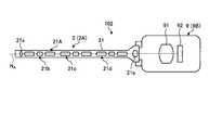
- FIG. 1is a diagram illustrating a schematic configuration of an endoscope apparatus according to the first embodiment of the present invention.
- FIG. 2is a block diagram showing the configuration of the camera head and control device shown in FIG.
- FIG. 3Ais a schematic diagram illustrating configurations of the endoscope and the camera head according to the first embodiment of the present invention.
- FIG. 3Bis a schematic diagram illustrating configurations of the endoscope and the camera head according to the first embodiment of the present invention.
- FIG. 3Cis a schematic diagram illustrating configurations of the endoscope and the camera head according to the first embodiment of the present invention.
- FIG. 3Dis a schematic diagram illustrating configurations of the endoscope and the camera head according to the first embodiment of the present invention.
- FIG. 3Ais a schematic diagram illustrating configurations of the endoscope and the camera head according to the first embodiment of the present invention.
- FIG. 3Bis a schematic diagram illustrating configurations of the endoscope and the camera head according to the first embodiment of the
- FIG. 4is a diagram for explaining the sensitivity of the observation-side filter provided during special light observation in the endoscope apparatus according to the first embodiment.
- FIG. 5is a diagram illustrating light emitted from the light source of the light source device in the endoscope apparatus according to the first embodiment.
- FIG. 6is a diagram illustrating the light transmittance of the light source side filter provided at the time of special light observation in the endoscope apparatus according to the first embodiment.
- FIG. 7is a diagram for explaining light emitted during special light observation in the endoscope apparatus according to the first embodiment.
- FIG. 8is a diagram for explaining the sensitivity of the image sensor included in the endoscope apparatus according to the first embodiment.
- FIG. 9is a diagram for explaining light incident on the endoscope in the special light observation in the endoscope apparatus according to the first embodiment.
- FIG. 10is a diagram for explaining light incident on the image sensor during special light observation in the endoscope apparatus according to the first embodiment.
- FIG. 11is a diagram for explaining a difference in incident light to the image pickup device depending on the presence or absence of an observation-side filter in the endoscope apparatus according to the first embodiment.
- FIG. 12is a diagram for explaining the detection value by the incident light shown in FIG.
- FIG. 13is a diagram illustrating light emitted from the light source of the light source device during normal observation in the endoscope apparatus according to the modification of the first embodiment.
- FIG. 14is a diagram illustrating light emitted from the light source of the light source device during special light observation in the endoscope apparatus according to the modification of the first embodiment.
- FIG. 15is a diagram illustrating light that enters the endoscope during special light observation in the endoscope apparatus according to the modification of the first embodiment.
- FIG. 16is a diagram for explaining light incident on the imaging element during special light observation in the endoscope apparatus according to the modification of the first embodiment.
- FIG. 17is a diagram for explaining a difference in incident light on the image sensor depending on the presence or absence of an observation-side filter in the endoscope apparatus according to the modification of the first embodiment.
- FIG. 18is a diagram for explaining the detection value by the incident light shown in FIG. FIG.
- FIG. 19is a schematic diagram illustrating configurations of the endoscope 2 and the camera head 9 according to the second modification of the first embodiment of the present invention.
- FIG. 20is a diagram illustrating a schematic configuration of the endoscope apparatus according to the second embodiment of the present invention.
- FIG. 21is a diagram schematically illustrating an entire configuration of a surgical microscope system that is a medical observation system including the medical imaging apparatus according to the third embodiment of the present invention.
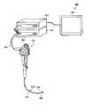
- FIG. 1is a diagram illustrating a schematic configuration of an endoscope apparatus 1 according to the first embodiment of the present invention.
- the endoscope apparatus 1is an apparatus that is used in the medical field and observes a subject inside (in vivo) an object to be observed such as a person.
- the endoscope apparatus 1includes an endoscope 2, an imaging device 3, a display device 4, a control device 5 (image processing device), and a light source device 6, and includes an imaging device. 3 and the control device 5 constitute a medical observation system.
- the endoscope 2 and the imaging device 3constitute an image acquisition device that uses an endoscope such as a rigid endoscope.
- the light source device 6is connected to one end of a light guide 7, and a light source unit that supplies illumination light such as white light or near-infrared light for special observation to illuminate the living body to one end of the light guide 7. 61, and a light source control unit 62 that controls the emission of illumination light by the light source unit 61.
- the light source unit 61includes an illumination optical system that emits illumination light, and an illumination-side filter that can be inserted into and removed from the optical path of the illumination light.
- the illumination side filteroperates under the control of the light source control unit 62.
- the light source device 6 and the control device 5may be configured separately and communicate with each other, or may be integrated.
- the light guide 7has one end detachably connected to the light source device 6 and the other end detachably connected to the endoscope 2.
- the light guide 7transmits the light supplied from the light source device 6 from one end to the other end and supplies the light to the endoscope 2.
- the imaging device 3captures a subject image from the endoscope 2 and outputs the imaging result.
- the imaging device 3includes a transmission cable 8 that is a signal transmission unit and a camera head 9.
- the transmission cable 8 and the camera head 9constitute a medical imaging device.
- the endoscope 2is hard and has an elongated shape, and is inserted into a living body. Inside the endoscope 2, an observation optical system configured to collect a subject image is provided by using one or a plurality of lenses. The endoscope 2 emits light supplied via the light guide 7 from the tip and irradiates the living body. The light (subject image) irradiated into the living body is collected by the observation optical system (lens unit 91) in the endoscope 2.
- the endoscope 2has a configuration including a filter that cuts light in a predetermined wavelength band (hereinafter referred to as an observation-side filter) and the observation-side filter. There is a configuration that does not. For example, when the light source device 6 emits light in the near-infrared wavelength band, the observation-side filter cuts light in the near-infrared wavelength band.
- the camera head 9is detachably connected to the proximal end of the endoscope 2. And the camera head 9 images the to-be-photographed object image condensed with the endoscope 2 under control of the control apparatus 5, and outputs the imaging signal by the said imaging.
- the detailed configuration of the camera head 9will be described later.
- the endoscope 2 and the camera head 9may be configured to be detachable as shown in FIG. 1 or may be configured to be integrated.
- the transmission cable 8is detachably connected to the control device 5 via a connector, and the other end is detachably connected to the camera head 9 via a connector.
- the transmission cable 8is a cable in which a plurality of electrical wirings (not shown) are disposed inside the outer jacket which is the outermost layer. The plurality of electrical wirings are used for transmitting an imaging signal output from the camera head 9 to the control device 5 and transmitting a control signal, a synchronization signal, a clock, and power output from the control device 5 to the camera head 9, respectively. Wiring.
- the display device 4displays an image generated by the control device 5 under the control of the control device 5.
- the display device 4preferably has a display unit of 55 inches or more in order to make it easy to obtain an immersive feeling during observation, but is not limited thereto.
- the control device 5processes an imaging signal input from the camera head 9 via the transmission cable 8 and outputs an image signal to the display device 4, and comprehensively controls the operations of the camera head 9 and the display device 4. To do. The detailed configuration of the control device 5 will be described later.
- FIG. 2is a block diagram illustrating configurations of the camera head 9 and the control device 5.
- illustration of a connector that allows the camera head 9 and the transmission cable 8 to be attached and detachedis omitted.
- the control device 5includes a signal processing unit 51, an image processing unit 52, a communication module 53, an input unit 54, an output unit 55, a control unit 56, and a memory 57.
- the control device 5generates a power supply voltage for driving the control device 5 and the camera head 9, supplies the power supply voltage to each part of the control device 5, and supplies power to the camera head 9 via the transmission cable 8.
- a part (not shown) or the likemay be provided.
- the signal processing unit 51performs image processing on the digitized imaging signal (pulse signal) by performing noise processing on the imaging signal output from the camera head 9 and performing signal processing such as A / D conversion as necessary.
- the datais output to the processing unit 52.
- the signal processing unit 51generates a synchronization signal and a clock for the imaging device 3 and the control device 5.
- a synchronization signalfor example, a synchronization signal for instructing the imaging timing of the camera head 9
- a clockfor example, a clock for serial communication
- the image processing unit 52generates an image signal for display displayed on the display device 4 based on the imaging signal input from the signal processing unit 51.
- the image processing unit 52performs predetermined signal processing on the imaging signal to generate a display image signal including a subject image.
- the image processing unit 52performs known image processing such as detection processing, interpolation processing, color correction processing, color enhancement processing, and various image processing such as contour enhancement processing.
- the image processing unit 52outputs the generated image signal to the display device 4.
- the image processing unit 52includes a filter detection unit 52a that detects whether or not a filter that cuts light of a predetermined wavelength band is inserted in the optical path based on the imaging signal. Details of the filter detection processing by the filter detection unit 52a will be described later.
- the communication module 53outputs a signal from the control device 5 including a later-described control signal transmitted from the control unit 56 to the imaging device 3.
- a signal from the imaging device 3is output to each unit in the control device 5. That is, the communication module 53 collectively outputs signals from the respective units of the control device 5 to be output to the imaging device 3 by, for example, parallel / serial conversion, and outputs signals input from the imaging device 3 by, for example, serial / parallel conversion. It is a relay device that distributes and outputs to each part of the control device 5.
- the input unit 54is realized by using a user interface such as a keyboard, a mouse, a touch panel, etc., and receives input of various information.
- a user interfacesuch as a keyboard, a mouse, a touch panel, etc.
- the output unit 55is realized using a speaker, a printer, a display, or the like, and outputs various types of information.
- the output unit 55outputs alarm sound and alarm light and displays an image under the control of the control unit 56. For example, when it is determined from the detection result by the filter detection unit 52 a that the observation side filter is not inserted in the optical path, the output unit 55 outputs an alarm sound and alarm light under the control of the control unit 56. To do.
- the control unit 56performs drive control of each component including the control device 5 and the camera head 9, and input / output control of information with respect to each component.
- the control unit 56generates a control signal with reference to communication information data (for example, communication format information) recorded in the memory 57, and the generated control signal is transmitted to the imaging device 3 via the communication module 53. Send to.
- the control unit 56outputs a control signal to the camera head 9 via the transmission cable 8.
- the control unit 56switches the wavelength band of the illumination light emitted from the light source device 6 in accordance with an observation method switching instruction input via the input unit 54.
- Observation methodsinclude normal observation in which white light is emitted and special light observation in which light having a wavelength band different from the white wavelength band is emitted.
- IRI observationin which light in the near-infrared wavelength band is emitted to observe indocyanine green fluorescence will be described as an example of special light observation.
- the memory 57is realized by using a semiconductor memory such as a flash memory or a DRAM (Dynamic Random Access Memory), and records communication information data (for example, communication format information).
- the memory 57may record various programs executed by the control unit 56.
- the signal processing unit 51outputs a predetermined AF evaluation value for each frame based on the input image signal of the frame, and the AF evaluation value for each frame from the AF processing unit.
- An AF calculation unitthat performs an AF calculation process that selects a frame or a focus lens position that is most suitable as a focus position may be provided.
- the signal processing unit 51, the image processing unit 52, the communication module 53, and the control unit 56 described aboveare a general-purpose processor such as a CPU (Central Processing Unit) having an internal memory (not shown) in which a program is recorded, or an ASIC (Application Specific Integrated). It is realized by using a dedicated processor such as various arithmetic circuits that execute a specific function such as Circuit). Further, an FPGA (Field Programmable Gate Array: not shown) which is a kind of programmable integrated circuit may be used. In the case of an FPGA, a memory for storing configuration data may be provided, and the FPGA that is a programmable integrated circuit may be configured by the configuration data read from the memory.
- a general-purpose processorsuch as a CPU (Central Processing Unit) having an internal memory (not shown) in which a program is recorded, or an ASIC (Application Specific Integrated). It is realized by using a dedicated processor such as various arithmetic circuits that execute a specific function such as Circuit).
- the camera head 9includes a lens unit 91, an imaging unit 92, a communication module 93, and a camera head control unit 94.
- the camera head 9has a configuration having an observation-side filter that cuts light in a predetermined wavelength band and a configuration not having this filter.
- the lens unit 91is configured by using one or a plurality of lenses, and forms a subject image that has passed through the lens unit 91 on an imaging surface of an imaging element that constitutes the imaging unit 92.
- the one or more lensesare configured to be movable along the optical axis.
- the lens unit 91is provided with an optical zoom mechanism (not shown) that changes the angle of view by moving the one or more lenses, and a focus mechanism that changes the focal position.
- the lens unit 91forms an observation optical system that guides the observation light incident on the endoscope 2 to the imaging unit 92 together with the optical system provided in the endoscope 2.
- the imaging unit 92images a subject under the control of the camera head control unit 94.
- the imaging unit 92is configured using an imaging element that receives a subject image formed by the lens unit 91 and converts it into an electrical signal.
- the image sensoris composed of a CCD (Charge Coupled Device) image sensor or a CMOS (Complementary Metal Oxide Semiconductor) image sensor.
- CMOSComplementary Metal Oxide Semiconductor
- the imaging deviceis a CMOS
- a signal processing unit(not shown) that performs signal processing (A / D conversion, etc.) on an electrical signal (analog signal) converted from light to an electrical signal and outputs an imaging signal.
- the imaging unit 92outputs the generated electrical signal to the communication module 93.
- the communication module 93outputs a signal transmitted from the control device 5 to each unit in the camera head 9 such as the camera head control unit 94. Further, the communication module 93 converts information about the current state of the camera head 9 into a signal format corresponding to a predetermined transmission method, and outputs the converted signal to the control device 5 via the transmission cable 8. . That is, the communication module 93 distributes a signal input from the control device 5 or the transmission cable 8 by, for example, serial / parallel conversion, and outputs the signal to each part of the camera head 9, and outputs to the control device 5 or the transmission cable 8. 9 is a relay device that collectively outputs signals from the respective units by, for example, parallel-serial conversion or the like.
- the camera head control unit 94is a drive signal input via the transmission cable 8, an instruction signal output from the operation unit by a user operation to an operation unit such as a switch provided exposed on the outer surface of the camera head 9, etc. In response to this, the overall operation of the camera head 9 is controlled. Further, the camera head control unit 94 outputs information on the current state of the camera head 9 to the control device 5 via the transmission cable 8.
- the communication module 93 and the camera head control unit 94 described aboveare a general-purpose processor such as a CPU having an internal memory (not shown) in which a program is recorded, and a dedicated processor such as various arithmetic circuits that execute specific functions such as an ASIC. It is realized using. Moreover, you may make it comprise using FPGA which is a kind of programmable integrated circuit.
- FPGAwhich is a kind of programmable integrated circuit.
- a memory for storing configuration datamay be provided, and the FPGA that is a programmable integrated circuit may be configured by configuration data read from the memory.
- a signal processing unit that performs signal processing on the imaging signal generated by the communication module 93 or the imaging unit 92may be configured in the camera head 9 or the transmission cable 8. Further, based on a reference clock generated by an oscillator (not shown) provided in the camera head 9, an imaging clock for driving the imaging unit 92 and a control clock for the camera head control unit 94 are provided. It may be generated and output to the imaging unit 92 and the camera head control unit 94, respectively, or based on the synchronization signal input from the control device 5 via the transmission cable 8, the imaging unit 92 and the camera head control unit 94. The timing signals of the various processes may be generated and output to the imaging unit 92 and the camera head control unit 94, respectively. Further, the camera head control unit 94 may be provided in the transmission cable 8 or the control device 5 instead of the camera head 9.
- FIGS. 3A to 3Dare schematic views for explaining the configuration of the endoscope 2 and the camera head 9 according to the embodiment of the present invention.
- the endoscope 2 and the camera head 9 attached to the control device 5there are endoscopes 2A and 2B and camera heads 9A and 9B as shown in FIGS. 3A to 3D.
- the endoscopes 2A and 2Btake in external light at the distal end side and connect to the camera head 9 (9A and 9B) at the proximal end side.
- the endoscope 2Aincludes an observation optical system 21A inside the insertion portion 21 (see, for example, FIG. 3A).
- the observation optical system 21Ahas an objective lens 21a, a first relay optical system 21b, a second relay optical system 21c, a third relay optical system 21d, and an eyepiece lens from the front end side along the optical axis N A of the observation optical system 21A. 21e are arranged in this order.
- the endoscope 2Bincludes an observation optical system 21B inside the insertion portion 21 (see, for example, FIG. 3C).
- the observation optical system 21Bincludes, along an optical axis N B of the observation optical system 21B, the observation-side filter 21f from the front end side, an objective lens 21a, the first relay optical system 21b, a second relay optical system 21c, a third relay optical The system 21d and the eyepiece 21e are arranged in this order.
- the endoscope 2Bis obtained by adding an observation-side filter 21f that cuts light in a predetermined wavelength band to the configuration of the endoscope 2A.
- the observation-side filter 21fmay be replaced with a filter that cuts light in a predetermined wavelength band by coating any one of the optical members constituting the observation optical system 21B.
- the camera head 9Ais arranged in the order of the observation side filter 95, the lens unit 91, and the imaging unit 92 from the side connected to the endoscope 2 (see, for example, FIG. 3A).
- the camera head 9Bis arranged in the order of the lens unit 91 and the imaging unit 92 from the side connected to the endoscope 2 (see, for example, FIG. 3B).
- the camera head 9Bis obtained by removing the observation-side filter 95 that cuts light in a predetermined wavelength band from the configuration of the camera head 9A.
- the image acquisition deviceis configured by the combination of the endoscope 2 and the camera head 9 (the transmission cable 8 is not shown in FIGS. 3A to 3D).
- the image acquisition device 101is configured by the endoscope 2A and the camera head 9A (see FIG. 3A)
- the image acquisition device 102is configured by the endoscope 2A and the camera head 9B (see FIG. 3B), and the endoscope 2B.
- the image acquisition apparatus 103is comprised by the camera head 9B (refer FIG. 3C).
- 3A to 3Cinclude a configuration in which the endoscope 2 and the camera head 9 are detachable, and a configuration in which the endoscope 2 and the camera head 9 are fixed (integrated). Including.
- an image acquisition device 104configured by providing an intermediate member 10 having an observation-side filter 10a between the endoscope 2A and the camera head 9B can also be used (See FIG. 3D).
- the intermediate member 10may be detachable with respect to the endoscope 2A and the camera head 9B, or may be configured such that the observation side filter 10a can be inserted and removed.
- any of the image acquisition devices 101 to 104 described aboveis selectively connected to the control device 5.
- observation side filters 10a, 21f, 95a configuration having one observation side filter (observation side filters 10a, 21f, 95), or an observation side filter (observation side filters 10a, 21f), depending on the combination of the endoscope 2 and the camera head 9. 95).
- observation side filter 21f, 95a structure which has two observation side filters (observation side filter 21f, 95) like the combination of the endoscope 2B and the camera head 9A, since there is only one observation side filter, here Then, it demonstrates using two patterns, the case where it has one observation side filter, and the case where it does not have.
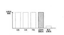
- FIG. 4is a diagram for explaining the sensitivity of the observation-side filter provided at the time of special light observation in the endoscope apparatus according to the first embodiment.
- the white light according to the first embodimentincludes light in a blue wavelength band (B light), light in a green wavelength band (G light), light in a red wavelength band (R light), and a near-infrared wavelength band.
- near-infrared excitation lightLight (hereinafter also referred to as near-infrared excitation light) and fluorescence (fluorescence self-emission) applied to the surface of the light source.
- the lightbecomes larger in wavelength toward the right side.
- the wavelength band of light used as near infrared excitation lightis, for example, 700 nm to 800 nm.
- the wavelength of fluorescenceis larger than the wavelength of near-infrared light used, and includes fluorescence due to indocyanine green and fluorescence derived from a light source.
- observation-side filterany of the observation-side filters 10a, 21f, and 95
- the observation-side filterhas low sensitivity to light in the near-infrared wavelength band emitted from the light source device 6 as illumination light (see FIG. 4B). For this reason, when the observation side filter is arranged, the light received by the imaging unit 92 is light in a wavelength band excluding the near-infrared wavelength band.
- FIG. 5is a diagram illustrating light emitted from the light source of the light source device in the endoscope apparatus according to the first embodiment.
- FIG. 5shows the light intensity when the light source included in the light source device 6 is a halogen lamp.
- the fluorescent self-emission included in the illumination light emitted from the halogen lampis fluorescence derived from the fluorescent paint applied to the surface of the halogen lamp.
- the horizontal axis of the graph shown belowdemonstrates as a wavelength becoming long, so that it goes to the right.
- FIG. 6is a diagram for explaining the light transmittance of the light source side filter provided at the time of special light observation in the endoscope apparatus according to the first embodiment.
- the illumination side filteris arranged on the illumination optical path in the light source device 6 under the control of the control unit 56.
- the filter transmittance of B light, G light, R light, and fluorescence self-emissionis smaller than the filter transmittance of near-infrared excitation light.
- the filter transmittance of R light and fluorescence self-light emissionis smaller than the filter transmittance of B light and G light.
- the illumination side filterit is assumed that the R light and the fluorescent light emission are substantially cut by the illumination side filter.
- FIG. 7is a diagram for explaining light emitted during special light observation in the endoscope apparatus according to the first embodiment.
- Light emitted from the light source shown in FIG. 5 and passed through the illumination-side filter shown in FIG. 6includes B light, G light, and near-infrared excitation light, as shown in FIG.
- the subjectis irradiated with special light including B light, G light, and near-infrared excitation light.
- special lightnear infrared excitation light
- the subject indocyanine greenis excited and emits fluorescence.
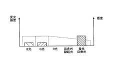
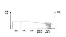
- FIG. 8is a diagram for explaining the sensitivity of the image sensor included in the endoscope apparatus according to the first embodiment.
- the imaging device included in the imaging unit 92has sensitivity to B light, G light, R light, near-infrared excitation light, and fluorescence self-emission.
- the sensitivity of R light, near-infrared excitation light, and fluorescence self-emissiondecreases as the wavelength increases.
- near-infrared excitation light and fluorescent self-emissionare received by a pixel that receives R light.
- 9 and 10are diagrams for explaining light incident on the endoscope during special light observation in the endoscope apparatus according to the first embodiment.
- 9 and 10show the intensity of each light (B light, G light, R light, near-infrared excitation light, and fluorescence self-emission).
- the broken line of FIG. 9has shown the transmittance
- the broken line in FIG. 10indicates the sensitivity of the imaging unit 92 (see FIG. 8).
- the observation light incident on the endoscope 2is emitted from the light source device 6 and reflected by the subject, such as B light, G light and near infrared excitation light, and fluorescence self-emission emitted from indocyanine green; including.
- the near-infrared excitation light of this observation lightis cut by the observation side filter. That is, the imaging unit 92 receives B light, G light, and fluorescent light emission (see FIG. 10).
- illumination lightincluding B light, G light, R light, near-infrared excitation light, and fluorescent self-emission is applied to the subject, and light reflected by the subject enters the imaging unit 92. .
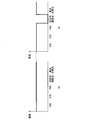
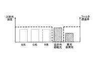
- FIG. 11is a diagram for explaining a difference in incident light to the image pickup device depending on the presence or absence of the observation side filter in the endoscope apparatus according to the first embodiment.
- the observation side filteris not provided in the normal observation, when the reflected light of the illumination light is received, the reflected light is B light, G light, R light, near infrared excitation light, and fluorescent light itself. Including light emission (see FIG. 11A).
- the illumination light filter and the observation side filterare provided, when the reflected light of the illumination light is received, the reflected light is B light, G light, R light, and fluorescence self-emission. (See FIG. 11B).
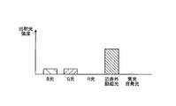
- FIG. 12is a diagram for explaining the detection value by the incident light shown in FIG.
- near-infrared excitation light and fluorescent self-emissionare processed as R light.
- the detection value when the observation-side filter is inserted on the optical pathis the detection value when the observation-side filter is not inserted on the optical path (FIG. ))
- the detection value (R value) of the R lightis lowered. This is because near-infrared excitation light from the observation side filter is cut.
- the detection value (B value) of B light and the detection value (G value) of G lightare not significantly different between normal observation and special light observation.
- the filter detection unit 52adetermines whether or not the observation side filter exists on the observation optical path by using the difference in the detection value (R value) depending on the presence or absence of the observation side filter. Specifically, the filter detection unit 52a sets a threshold for the detection value (here, R value), and determines whether or not the obtained detection value is equal to or greater than the threshold TH.
- the threshold THis, for example, at least one of the wavelength (wavelength band) of light emitted from the light source, the sensitivity of the image sensor, the spectral characteristics (attenuation rate) of the lens, and the change rate of the detection value depending on the presence or absence of the observation side filter. It is set based on one.
- the filter detection unit 52adetermines that there is no observation-side filter on the observation optical path. On the other hand, if the R value is less than the threshold value TH, the filter detection unit 52a determines that the observation side filter exists on the observation optical path.
- the above-described filter detection processis executed at the time of calibration for performing the white balance adjustment process, for example. Specifically, before a start of use of the endoscope 2, when a calibration instruction is input from the user via a button or the like provided on the input unit 54 or the camera head 9, the control unit 56 performs a calibration process (for example, White balance adjustment processing) and filter detection processing. Note that the filter detection process is executed not only during the above-described white balance adjustment process but also when an instruction is given from the user via a button or the like provided on the input unit 54 or the camera head 9.
- a calibration processfor example, White balance adjustment processing
- the control unit 56When acquiring the detection result from the filter detection unit 52a, the control unit 56 performs color mode setting, notification processing, and illumination light emission control.
- the color mode setting processwhen it is determined that the observation side filter does not exist on the observation optical path, the color mode of the normal white light image is set. In a normal white light image color mode, color correction for reproducing appropriate white color is performed.
- the color mode corresponding to the image not including the near infrared excitation lightis set. In the color mode of an image that does not include near-infrared excitation light, color correction is performed by increasing the red (R) gain value.
- the control unit 56may perform control to permit setting to the mode at the time of fluorescence observation.
- the notification processfor example, when the filter detection unit 52a determines that there is no observation-side filter on the observation optical path, when an instruction to perform special light observation is input via the input unit 54, the observation-side filter Notification that there is no.
- the observation-side filterNotification that there is no.
- FIG. 3Bwhen the observation side filter is not provided in both the endoscope 2 (2A) and the camera head 9 (9B), an instruction to perform special light observation is input via the input unit 54. When this is done, a notification is made that there is no observation side filter.
- the notification process at this timeis executed by character information (image) displayed by the display device 4, sound output from the output unit 55, light, and the like. Further, when it is determined that the observation side filter is not present on the observation optical path, the emission of the special light from the light source device 6 is stopped when an instruction to perform special light observation is input via the input unit 54. When the presence of the observation-side filter is detected on the observation optical path, the control unit 56 releases the special light emission stop.
- the light source control unit 62controls light emission by the light source unit 61 under the control of the control unit 56.
- the control unit 56performs at least one of the notification process and the illumination light control described above according to the detection result of the filter detection unit 52a.
- the first embodiment described aboveit is possible to detect the presence or absence of the observation-side filter using the detection value without separately providing a detection block. According to the first embodiment, it is possible to detect the presence or absence of a filter in the observation optical system while suppressing an increase in circuit scale. Thereby, it is possible to prevent erroneous observation due to the presence or absence of the filter, in particular, special light observation in a state where the observation side filter is not on the observation optical path. Further, according to the above-described first embodiment, it is possible to perform observation in an observation mode (color mode) corresponding to the type of the endoscope 2.
- an observation modecolor mode
- the modification 1 of Embodiment 1 of this inventionis demonstrated.
- the endoscope apparatus according to the first modificationdiffers only in the light source provided in the light source apparatus 6, and other configurations are the same as those of the endoscope apparatus 1 described above.
- the light source device 6includes an LED (Light Emitting Diode) that emits white light and a semiconductor laser that emits light in the near-infrared wavelength band as a light source. Under the control of the control unit 56, the LED light source emits light during normal observation, and the semiconductor laser emits light during special light observation.
- LEDLight Emitting Diode
- FIG. 13is a diagram illustrating light emitted from the light source of the light source device during normal observation in the endoscope apparatus according to the first modification.
- FIG. 13shows the intensity of light in the case of an LED.
- the lightbecomes larger in wavelength toward the right side.
- the light emitted from the LED light sourceincludes light in the blue wavelength band (B light), light in the green wavelength band (G light), and light in the red wavelength band (R light). .
- B lightblue wavelength band
- G lightgreen wavelength band
- R lightred wavelength band
- near-infrared excitation light and fluorescent self-emissionare not emitted, and therefore, when observing special light, it is switched to light emission from a semiconductor laser.
- FIG. 14is a diagram for explaining light emitted from the light source of the light source device during special light observation in the endoscope apparatus according to the first modification.
- FIG. 14shows the light intensity of a semiconductor laser that emits light in the near-infrared wavelength band. As shown in FIG. 14, the light emitted from the semiconductor laser is near infrared excitation light.
- the fluorescence self-light emission shown in FIG. 13 and FIG. 14shows the fluorescence emitted by indocyanine green.
- 15 and 16are diagrams for explaining light incident on the endoscope during special light observation in the endoscope apparatus according to the first modification of the first embodiment.
- 15 and 16show the intensity of each light (B light, G light, R light, near-infrared excitation light, and fluorescence self-emission).
- the broken line of FIG. 15has shown the transmittance
- the broken line in FIG. 16indicates the sensitivity of the imaging unit 92 (see FIG. 8).
- the observation light incident on the endoscope 2 at the time of special light observationis emitted from the light source device 6 and reflected by near-infrared excitation light reflected by the subject, and fluorescence self-emission emitted by indoocyanine green. (See FIG. 15).
- the near-infrared excitation light of this observation lightis cut by the observation side filter. That is, the imaging unit 92 receives only the fluorescence emitted by indocyanine green (see FIG. 16).
- illumination lightincluding B light, G light, and R light is irradiated on the subject, and light reflected by the subject enters the imaging unit 92.
- FIG. 17is a diagram for explaining a difference in incident light to the image sensor depending on the presence or absence of the observation side filter in the endoscope apparatus according to the first modification of the first embodiment.
- the light received by the imaging unit 92consists only of near-infrared excitation light (see FIG. 17A).
- the imaging unit 92reflects the reflected light (near-infrared excitation light). ) Is not received (see FIG. 17B).
- FIG. 18is a diagram for explaining the detection value by the incident light shown in FIG.
- near-infrared excitation lightis processed as R light, so that the R value when the observation-side filter is not inserted on the optical path is a value corresponding to the reflected light of the near-infrared excitation light (FIG. 18 (a)).
- the R valueis zero when the observation-side filter is inserted on the optical path (see FIG. 18B).
- the filter detection processis executed, for example, during the white balance adjustment process or after the white balance adjustment process.
- the filter detection unit 52adetermines whether or not the observation side filter exists on the observation optical path by using the difference in the detection value depending on the presence or absence of the observation side filter. Specifically, the filter detection unit 52a determines whether or not an R value is obtained. If the R value is obtained, the filter detection unit 52a determines that there is no observation-side filter on the observation optical path. On the other hand, when the detection value is not obtained, the filter detection unit 52a determines that the observation side filter exists on the observation optical path.
- control unit 56When the control unit 56 acquires the detection result from the filter detection unit 52a, the control unit 56 performs at least one of the above-described notification processing, illumination light control, and color mode setting control according to the detection result of the filter detection unit 52a.
- FIG. 19is a schematic diagram illustrating configurations of the endoscope 2 and the camera head 9 according to the second modification of the first embodiment of the present invention.
- a combination of the endoscope 2A, the camera head 9B, and the intermediate member 10Awill be described as an example.
- the treatment by irradiating the object S with the laser beam L G of predetermined wavelengths contained in the green wavelength band (or wavelength band)is subjected.
- the light of the wavelength of the laser beam L G (or wavelength band)by cutting the observation side filter suppresses changes in brightness of an image by the laser beam L G.
- the intermediate member 10Ahas a viewing side filter 10b for cutting light components having a wavelength band of the laser beam L G.
- the filter detection unit 52adetects whether or not the observation side filter (here, the observation side filter 10b) is disposed in the observation optical system in the same manner as the R value in the first embodiment.
- the filter detection unit 52adetects the presence or absence of the observation side filter 10b in the observation optical system using the difference in the G light detection value (G value) depending on the presence or absence of the observation side filter 10b as in the first embodiment. To do.
- the control unit 56performs notification processing and illumination light control based on the detection result of the observation side filter.
- a message indicating that the observation-side filter should be attachedis displayed when using the laser treatment instrument 11, and sound and / or light are displayed. To inform that the observation side filter should be attached.
- the control unit 56can control the light emission of the laser treatment instrument 11, it may be controlled to prohibit the light emission of the laser treatment instrument 11 when it is detected that the observation side filter is not arranged.
- the second modificationby detecting the presence or absence of the observation side filter 10b, by prompting the installation of observation side filter 10b in the use of laser treatment instrument, suppressing the brightness change of the display image by the laser beam L G can do. Since the intensity of the laser light used for the treatment of the subject is larger than the intensity of the illumination light emitted from the light source device 6, if the imaging unit 92 receives the laser light, an observation image may not be obtained appropriately. By providing the observation side filter, an image suitable for observation can be generated.
- FIG. 20is a diagram illustrating a schematic configuration of the endoscope apparatus 200 according to the second embodiment of the present invention.
- the endoscope apparatus 1 using a rigid endoscopehas been described as the endoscope 2.
- the present inventionis not limited to this, and an endoscope apparatus using a flexible endoscope may be used.
- an observation-side filter and an imaging unitare provided at the distal end of an insertion portion of a flexible endoscope.
- the endoscope apparatus 200includes an endoscope 201 that captures an in-vivo image of an observation site by inserting an insertion unit 202 into a subject and generates an imaging signal, and illumination light emitted from the distal end of the endoscope 20. , A control device 220 that performs overall image processing on the imaging signal acquired by the endoscope 201, and controls the overall operation of the endoscope device 200. And a display device 230 that displays the processed in-vivo image.
- the endoscope apparatus 200acquires an in-vivo image in the subject by inserting the insertion unit 202 into the subject such as a patient.
- the control device 220has functions such as the signal processing unit 51 and the image processing unit 52 (including the filter detection unit 52a) described above.
- the endoscope 201includes an insertion portion 202 having an elongated shape having flexibility, an operation portion 203 that is connected to the proximal end side of the insertion portion 202 and receives input of various operation signals, and an insertion portion from the operation portion 203.
- a universal cord 204that extends in a direction different from the direction in which 202 extends and incorporates various cables connected to the light source device 210 and the control device 220.
- the insertion unit 202is connected to the distal end portion 205 including the imaging unit according to the first embodiment, the bendable bending portion 206 formed of a plurality of bending pieces, and the proximal end side of the bending portion 206, and is allowed. And a long flexible tube portion 207 having flexibility.
- the endoscope 201is connected to the control device 220 by any one of the endoscope having the observation side filter, the endoscope not having the observation side filter, and the endoscope having the observation side filter removable.
- the observation side filteris provided, for example, in the front stage of the imaging unit.
- the light source device 210has a configuration capable of switching emission of white light and near-infrared excitation light. Specifically, the light source device 210 emits white light and special light by a combination of a halogen lamp and an illumination-side filter, or emits white light and an LED and near-infrared excitation light. Any of the structures having a semiconductor laser is provided.
- the filter detection unit 52adetects whether or not the observation-side filter is arranged in the endoscope 201 in the same manner as in the first embodiment and the modification.
- the control device 220performs notification processing and illumination light control based on the detection result of the observation side filter.
- the endoscope apparatus 200 including the flexible endoscope 201can obtain the same effects as those of the first embodiment described above.
- FIG. 21is a diagram schematically illustrating an entire configuration of a surgical microscope system that is a medical observation system including the medical imaging apparatus according to the third embodiment.
- a rigid or flexible endoscopehas been described as an example.
- a function of displaying a captured image by enlarging and capturing a predetermined visual field regionis described.
- a surgical microscope system(medical image acquisition system) will be described as an example.
- the surgical microscope system 300includes a microscope apparatus 310 that is a medical imaging apparatus that is acquired by capturing an image for observing a subject, and a display device 311 that displays an image captured by the microscope apparatus 310.
- the display device 311can be configured integrally with the microscope device 310.
- the microscope apparatus 310includes a microscope unit 312 that magnifies and images a minute part of a subject, a support unit 313 that includes an arm that is connected to the proximal end of the microscope unit 312 and rotatably supports the microscope unit 312, A base portion 314 that holds the base end portion of the portion 313 in a rotatable manner and is movable on the floor surface.
- the base unit 314includes a control unit 314 a that controls the operation of the surgical microscope system 300, and a light source unit 315 that generates illumination light that is applied to the subject from the microscope apparatus 310.
- the control unit 314ahas functions such as the signal processing unit 51 and the image processing unit 52 (including the filter detection unit 52a) described above.
- the base portion 314may be configured to support the support portion 313 by being fixed to a ceiling, a wall surface, or the like, instead of being provided on the floor surface.
- the microscope unit 312has, for example, a cylindrical shape and includes the above-described imaging unit 92 inside. On the side surface of the microscope unit 312, a switch that receives an input of an operation instruction for the microscope apparatus 310 is provided. A cover glass for protecting the inside is provided on the opening surface at the lower end of the microscope unit 312 (not shown).
- the microscope apparatus 310can be applied with any of the configuration in which the microscope unit 312 has the above-described observation-side filter, the configuration without the observation-side filter, and the configuration in which the observation-side filter is detachable.
- the observation side filteris provided, for example, before the imaging unit in the microscope unit 312.
- the light source unit 315has a configuration capable of switching emission of white light and near-infrared excitation light. Specifically, the light source unit 315 emits white light and special light by a combination of a halogen lamp and an illumination side filter, or emits white light and an LED and near infrared excitation light. Any of the structures having a semiconductor laser is provided.
- a usersuch as an operator moves the microscope unit 312, performs a zoom operation, or switches illumination light while operating various switches while holding the microscope unit 312.
- the shape of the microscope unit 312is preferably a shape that is elongated in the observation direction so that the user can easily grasp and change the viewing direction. For this reason, the shape of the microscope unit 312 may be a shape other than a cylindrical shape, for example, a polygonal column shape.
- the filter detection unit 52adetects whether or not the observation side filter is arranged in the microscope unit 312 as in the first embodiment and the modification. In the control unit 314a, notification processing and illumination light control are performed based on the detection result of the observation side filter.
- the surgical microscope system 300can obtain the same effects as those of the first embodiment.
- control device 5has been described as performing signal processing and the like, but may be performed on the camera head 9 side.
- the medical observation system according to the present inventionis useful for detecting the presence or absence of a filter in the observation optical system while suppressing an increase in circuit scale.
Landscapes
- Health & Medical Sciences (AREA)
- Life Sciences & Earth Sciences (AREA)
- Surgery (AREA)
- Physics & Mathematics (AREA)
- Engineering & Computer Science (AREA)
- Optics & Photonics (AREA)
- Biomedical Technology (AREA)
- General Health & Medical Sciences (AREA)
- Pathology (AREA)
- Nuclear Medicine, Radiotherapy & Molecular Imaging (AREA)
- Biophysics (AREA)
- Heart & Thoracic Surgery (AREA)
- Medical Informatics (AREA)
- Molecular Biology (AREA)
- Animal Behavior & Ethology (AREA)
- Radiology & Medical Imaging (AREA)
- Public Health (AREA)
- Veterinary Medicine (AREA)
- General Physics & Mathematics (AREA)
- Signal Processing (AREA)
- Multimedia (AREA)
- Astronomy & Astrophysics (AREA)
- Endoscopes (AREA)
Abstract
Description
Translated fromJapanese本発明は、医療用観察システムに関する。The present invention relates to a medical observation system.
近年、白色による通常観察とは別に、特殊光による特殊光観察を行なう観察方法が考案されている。具体的に、特殊光観察として、NBI(Narrow Band Imaging)と呼ばれる技術、IRI(Infra-Red Imaging)と呼ばれる技術、AFI(Auto Fluorescence Imaging)と呼ばれる技術、PDD(Photodynamic Diagnosis)と呼ばれる技術、などが挙げられる。
NBIでは、波長415nm及び540nmを中心波長とする狭帯域の照明光を照射して、各波長の光のヘモグロビンに対する吸収の差を利用して粘膜表層とそれより深い層との血管の状態を観察する。ここで、415nmの光は粘膜表層のヘモグロビンに吸収され、540nmの光はそれよりやや深い層のヘモグロビンに吸収される。
IRIでは、血中内で波長805nm付近の近赤外光に吸収ピークを持つインドシアニングリーン(Indocyanine green:ICG)という薬剤を造影剤として静脈注射し、中心波長805nm及び中心波長940nmの近赤外光を照射して、ICGの吸収による粘膜下層の血管部分の陰影を観察し、血管、リンパ管の走行状態を診断する。IRIでは、腫瘍の有無により、中心波長805nmの光の強度が変化する。
AFIでは、蛍光剤を被検体内に予め投与しておき、励起光を照射することによって、被検体から発せられる蛍光像を観察し、その蛍光像の有無や、形状を観察することにより腫瘍部分を診断する。正常な組織では粘膜表層において蛍光剤からの蛍光が発せられ、病変による粘膜表層において血管の集積や粘膜の肥厚が起こると蛍光体からの蛍光が著しく低下する。
PDDでは、アミノレブリン酸(5-ALA)の溶解液を患者に服用させると体内の正常組織では、血液原料(ヘム)に代謝されるが、癌細胞では、代謝されずに、その中間産物のPpIXという物質として蓄積され、このPpIXに青色光(中心波長410nm)を照射すると赤色(ピーク波長630nm)に蛍光発光するという性質を利用して、癌細胞と正常細胞を区別しやすい画像を得る。なお、正常細胞は、照射された青色光の光、例えば照射された青色光の裾野の460nmの光を受けて青色の光を発する。In recent years, an observation method for performing special light observation using special light has been devised separately from normal observation using white light. Specifically, as special light observation, a technique called NBI (Narrow Band Imaging), a technique called IRI (Infra-Red Imaging), a technique called AFI (Auto Fluorescence Imaging), a technique called PDD (Photodynamic Diagnosis), etc. Is mentioned.
NBI irradiates narrow band illumination light with wavelengths of 415 nm and 540 nm as central wavelengths, and observes the state of blood vessels between the mucosal surface layer and deeper layers using the difference in absorption of light of each wavelength with hemoglobin To do. Here, light at 415 nm is absorbed by hemoglobin on the surface of the mucosa, and light at 540 nm is absorbed by hemoglobin at a slightly deeper layer.
In IRI, a drug called indocyanine green (ICG) having an absorption peak in the near-infrared light having a wavelength of around 805 nm in blood is intravenously injected as a contrast agent, and a near-infrared light having a central wavelength of 805 nm and a central wavelength of 940 nm. By irradiating light, the shadow of the blood vessel portion in the submucosal layer due to absorption of ICG is observed, and the running state of blood vessels and lymphatic vessels is diagnosed. In IRI, the intensity of light having a central wavelength of 805 nm changes depending on the presence or absence of a tumor.
In AFI, a fluorescent agent is administered into a subject in advance and irradiated with excitation light to observe a fluorescent image emitted from the subject, and the presence or absence of the fluorescent image and the shape of the tumor are observed. Diagnose. In normal tissues, fluorescence from the fluorescent agent is emitted in the mucosal surface layer, and when the accumulation of blood vessels or thickening of the mucosa occurs in the mucosal surface layer due to a lesion, the fluorescence from the phosphor is significantly reduced.
In PDD, when a patient's solution of aminolevulinic acid (5-ALA) is taken by a patient, it is metabolized into blood raw material (heme) in normal tissues in the body, but in cancer cells, it is not metabolized and its intermediate product PpIX Using this property, when PpIX is irradiated with blue light (center wavelength: 410 nm), it emits red light (peak wavelength: 630 nm), thereby obtaining an image that makes it easy to distinguish cancer cells from normal cells. The normal cell emits blue light upon receiving irradiated blue light, for example, 460 nm light at the base of the irradiated blue light.
特殊光観察を行う際、例えば、IRIや、AFI、PDDは、蛍光色素や蛍光標識を励起するための励起光を照射する。この際、観察光学系には、被写体が励起光を反射し、この反射光が撮像素子に入射することを防ぐために、励起波長帯域の光をカットするフィルタが設けられる(例えば、特許文献1を参照)。When performing special light observation, for example, IRI, AFI, and PDD irradiate excitation light for exciting fluorescent dyes and fluorescent labels. At this time, the observation optical system is provided with a filter that cuts off the light in the excitation wavelength band in order to prevent the subject from reflecting the excitation light and the reflected light from entering the image sensor (for example, see Patent Document 1). reference).
特殊光観察を行う際、上述したフィルタを観察光学系に配置する必要があるため、観察光学系におけるフィルタの有無を検知することが望まれる。従来では、硬性鏡のアイピースのマスク形状を検出することによって硬性鏡の種別を検知する検知ブロックを設ける技術が知られているが、検知ブロックを設けると、回路規模が増大してしまう。When performing special light observation, since it is necessary to arrange the above-described filter in the observation optical system, it is desired to detect the presence or absence of the filter in the observation optical system. Conventionally, a technique of providing a detection block for detecting the type of a rigid endoscope by detecting the mask shape of the eyepiece of the rigid endoscope is known. However, if a detection block is provided, the circuit scale increases.
本発明は、上記に鑑みてなされたものであって、回路規模の増大を抑制しつつ、観察光学系におけるフィルタの有無を検知することができる医療用観察システムを提供することを目的とする。The present invention has been made in view of the above, and an object thereof is to provide a medical observation system capable of detecting the presence or absence of a filter in an observation optical system while suppressing an increase in circuit scale.
上述した課題を解決し、目的を達成するために、本発明にかかる医療用観察システムは、被写体からの観察光を導光する観察光学系と、前記観察光学系から観察光を受光して画像信号を生成する撮像部と、前記撮像部が生成した前記画像信号に信号処理を施す画像処理部と、を備え、前記画像処理部は、前記画像信号における予め設定された波長帯域の特定光の波長帯域を含む色の信号値に基づいて、前記観察光の光路上に、前記特定光をカットする観察側フィルタが配置されているか否かを検知するフィルタ検知部、を有することを特徴とする。In order to solve the above-described problems and achieve the object, a medical observation system according to the present invention includes an observation optical system that guides observation light from a subject, and an image obtained by receiving observation light from the observation optical system. An image processing unit that generates a signal; and an image processing unit that performs signal processing on the image signal generated by the image capturing unit, wherein the image processing unit is configured to transmit specific light in a predetermined wavelength band in the image signal. A filter detection unit that detects whether or not an observation-side filter that cuts the specific light is arranged on the optical path of the observation light based on a signal value of a color including a wavelength band. .
また、本発明にかかる医療用観察システムは、上記発明において、前記観察側フィルタは、前記観察光の光路に対して挿抜自在であることを特徴とする。The medical observation system according to the present invention is characterized in that, in the above invention, the observation-side filter is insertable / removable with respect to the optical path of the observation light.
また、本発明にかかる医療用観察システムは、上記発明において、外部からの指示の入力を受け付ける入力部をさらに備え、前記フィルタ検知部は、前記入力部にホワイトバランス調整処理の指示が入力された場合に、前記観察側フィルタの検知処理を実行することを特徴とする。The medical observation system according to the present invention further includes an input unit that receives an input of an instruction from the outside in the above invention, and the filter detection unit receives an instruction for white balance adjustment processing in the input unit. In this case, the observation-side filter detection process is executed.
また、本発明にかかる医療用観察システムは、上記発明において、前記フィルタ検知部の検知結果によって、前記観察光の光路上前記観察側フィルタが存在しないと判断した場合に、表示装置および/または出力部に、前記観察側フィルタが装着されていない旨の報知処理を実行させる制御部、をさらに備えることを特徴とする。In the medical observation system according to the present invention, in the above invention, the display device and / or the output when it is determined by the detection result of the filter detection unit that the observation-side filter is not present on the optical path of the observation light. The apparatus further includes a control unit that executes notification processing to the effect that the observation-side filter is not attached.
また、本発明にかかる医療用観察システムは、上記発明において、少なくとも前記特定光を含む照明光を出射する光源部、をさらに備えることを特徴とする。Further, the medical observation system according to the present invention is characterized in that in the above invention, the medical observation system further includes a light source unit that emits illumination light including at least the specific light.
また、本発明にかかる医療用観察システムは、上記発明において、前記フィルタ検知部の検知結果によって、前記観察光の光路上前記観察側フィルタが存在しないと判断された場合に、前記光源部による前記照明光の出射を制御する光源制御部、をさらに備えることを特徴とする。In the medical observation system according to the present invention, in the above invention, when it is determined by the detection result of the filter detection unit that the observation-side filter is not present on the optical path of the observation light, the light source unit A light source control unit that controls the emission of illumination light is further provided.
本発明によれば、回路規模の増大を抑制しつつ、観察光学系におけるフィルタの有無を検知することができるという効果を奏する。According to the present invention, it is possible to detect the presence or absence of a filter in the observation optical system while suppressing an increase in circuit scale.
以下、本発明を実施するための形態(以下、「実施の形態」という)を説明する。実施の形態では、本発明にかかる医療用観察システムの一例として、患者等の被検体内の画像を撮像して表示する医療用の内視鏡装置について説明する。また、この実施の形態により、この発明が限定されるものではない。さらに、図面の記載において、同一部分には同一の符号を付して説明する。Hereinafter, modes for carrying out the present invention (hereinafter referred to as “embodiments”) will be described. In the embodiment, as an example of a medical observation system according to the present invention, a medical endoscope apparatus that captures and displays an image in a subject such as a patient will be described. Moreover, this invention is not limited by this embodiment. Furthermore, in the description of the drawings, the same portions will be described with the same reference numerals.
(実施の形態1)
図1は、本発明の実施の形態1にかかる内視鏡装置1の概略構成を示す図である。内視鏡装置1は、医療分野において用いられ、人等の観察対象物の内部(生体内)の被写体を観察する装置である。この内視鏡装置1は、図1に示すように、内視鏡2と、撮像装置3と、表示装置4と、制御装置5(画像処理装置)と、光源装置6とを備え、撮像装置3と制御装置5とで、医療用観察システムを構成している。なお、本実施の形態1では、内視鏡2及び撮像装置3により、例えば硬性鏡等の内視鏡を用いた画像取得装置を構成している。(Embodiment 1)
FIG. 1 is a diagram illustrating a schematic configuration of an
光源装置6は、ライトガイド7の一端が接続され、当該ライトガイド7の一端に生体内を照明するための例えば白色光や、特殊観察用の近赤外光等の照明光を供給する光源部61と、光源部61による照明光の出射を制御する光源制御部62と、を有する。光源部61は、照明光を出射する照明光学系、照明光の光路に挿抜自在に設けられる照明側フィルタを含む。照明側フィルタは、光源制御部62の制御のもとで動作する。なお、光源装置6と制御装置5とは、図1に示すように別体とし相互に通信する構成としてもよいし、一体化した構成であってもよい。The
ライトガイド7は、一端が光源装置6に着脱自在に接続されるとともに、他端が内視鏡2に着脱自在に接続される。そして、ライトガイド7は、光源装置6から供給された光を一端から他端に伝達し、内視鏡2に供給する。The light guide 7 has one end detachably connected to the
撮像装置3は、内視鏡2からの被写体像を撮像して当該撮像結果を出力する。この撮像装置3は、図1に示すように、信号伝送部である伝送ケーブル8と、カメラヘッド9とを備える。本実施の形態1では、伝送ケーブル8とカメラヘッド9とにより医療用撮像装置が構成される。The
内視鏡2は、硬質で細長形状を有し、生体内に挿入される。この内視鏡2の内部には、1または複数のレンズを用いて構成され、被写体像を集光する観察光学系が設けられている。内視鏡2は、ライトガイド7を介して供給された光を先端から出射し、生体内に照射する。そして、生体内に照射された光(被写体像)は、内視鏡2内の観察光学系(レンズユニット91)により集光される。なお、本実施の形態1では、後述するように、内視鏡2には、所定の波長帯域の光をカットするフィルタ(以下、観察側フィルタという)を有する構成と、この観察側フィルタを有しない構成とが存在する。例えば、光源装置6が近赤外の波長帯域の光を出射する場合、観察側フィルタは、この近赤外の波長帯域の光をカットする。The
カメラヘッド9は、内視鏡2の基端に着脱自在に接続される。そして、カメラヘッド9は、制御装置5による制御の下、内視鏡2にて集光された被写体像を撮像し、当該撮像による撮像信号を出力する。なお、カメラヘッド9の詳細な構成については、後述する。内視鏡2とカメラヘッド9とは、図1に示すように着脱自在に構成してもよいし、一体化した構成であってもよい。The
伝送ケーブル8は、一端がコネクタを介して制御装置5に着脱自在に接続されるとともに、他端がコネクタを介してカメラヘッド9に着脱自在に接続される。具体的に、伝送ケーブル8は、最外層である外被の内側に複数の電気配線(図示略)が配設されたケーブルである。当該複数の電気配線は、カメラヘッド9から出力される撮像信号を制御装置5に、制御装置5から出力される制御信号、同期信号、クロック、及び電力をカメラヘッド9にそれぞれ伝送するための電気配線である。One end of the
表示装置4は、制御装置5による制御のもと、制御装置5により生成された画像を表示する。表示装置4は、観察時の没入感を得やすくするために、表示部が55インチ以上を有するものが好ましいが、これに限らない。The
制御装置5は、カメラヘッド9から伝送ケーブル8を経由して入力された撮像信号を処理し、表示装置4へ画像信号を出力するとともに、カメラヘッド9及び表示装置4の動作を統括的に制御する。なお、制御装置5の詳細な構成については、後述する。The
次に、撮像装置3及び制御装置5の構成について説明する。図2は、カメラヘッド9及び制御装置5の構成を示すブロック図である。なお、図2では、カメラヘッド9及び伝送ケーブル8同士を着脱可能とするコネクタの図示を省略している。Next, the configuration of the
以下、制御装置5の構成、及びカメラヘッド9の構成の順に説明する。なお、以下では、制御装置5の構成として、本発明の要部を主に説明する。制御装置5は、図2に示すように、信号処理部51と、画像処理部52と、通信モジュール53と、入力部54と、出力部55と、制御部56と、メモリ57とを備える。なお、制御装置5には、制御装置5及びカメラヘッド9を駆動するための電源電圧を生成し、制御装置5の各部にそれぞれ供給するとともに、伝送ケーブル8を介してカメラヘッド9に供給する電源部(図示略)などが設けられていてもよい。Hereinafter, the configuration of the
信号処理部51は、カメラヘッド9が出力した撮像信号に対してノイズ除去や、必要に応じてA/D変換等の信号処理を行うことによって、デジタル化された撮像信号(パルス信号)を画像処理部52に出力する。The
また、信号処理部51は、撮像装置3及び制御装置5の同期信号、及びクロックを生成する。撮像装置3への同期信号(例えば、カメラヘッド9の撮像タイミングを指示する同期信号等)やクロック(例えばシリアル通信用のクロック)は、図示しないラインで撮像装置3に送られ、この同期信号やクロックを基に、撮像装置3は駆動する。Further, the
画像処理部52は、信号処理部51から入力される撮像信号をもとに、表示装置4が表示する表示用の画像信号を生成する。画像処理部52は、撮像信号に対して、所定の信号処理を実行して被写体画像を含む表示用の画像信号を生成する。ここで、画像処理部52は、検波処理や、補間処理、色補正処理、色強調処理、及び輪郭強調処理等の各種画像処理等の公知の画像処理を行う。画像処理部52は、生成した画像信号を表示装置4に出力する。The
また、画像処理部52は、撮像信号に基づいて、所定の波長帯域の光をカットするフィルタが光路中に挿入されているか否かを検知するフィルタ検知部52aを有する。フィルタ検知部52aによるフィルタ検知処理の詳細については後述する。Further, the
通信モジュール53は、制御部56から送信された後述する制御信号を含む制御装置5からの信号を撮像装置3に出力する。また、撮像装置3からの信号を制御装置5内の各部に出力する。つまり通信モジュール53は、撮像装置3へ出力する制御装置5の各部からの信号を、例えばパラレルシリアル変換等によりまとめて出力し、また撮像装置3から入力される信号を、例えばシリアルパラレル変換等により振り分け、制御装置5の各部に出力する、中継デバイスである。The
入力部54は、キーボード、マウス、タッチパネル等のユーザインタフェースを用いて実現され、各種情報の入力を受け付ける。The input unit 54 is realized by using a user interface such as a keyboard, a mouse, a touch panel, etc., and receives input of various information.
出力部55は、スピーカーやプリンタ、ディスプレイ等を用いて実現され、各種情報を出力する。出力部55は、制御部56の制御のもと、アラーム音声、アラーム光の出力や、画像表示を行う。例えば、フィルタ検知部52aによる検知結果から、観察側フィルタが光路中に挿入されていないと判断される場合に、出力部55は、制御部56の制御のもと、アラーム音、アラーム光を出力する。The
制御部56は、制御装置5及びカメラヘッド9を含む各構成部の駆動制御、及び各構成部に対する情報の入出力制御などを行う。制御部56は、メモリ57に記録されている通信情報データ(例えば、通信用フォーマット情報など)を参照して制御信号を生成し、該生成した制御信号を、通信モジュール53を介して撮像装置3へ送信する。また、制御部56は、伝送ケーブル8を介して、カメラヘッド9に対して制御信号を出力する。制御部56は、例えば、入力部54を介して入力される観察法の切替指示により、光源装置6が出射する照明光の波長帯域を切り替える。観察法としては、白色光を出射する通常観察と、白色の波長帯域と異なる波長帯域の光を出射する特殊光観察とがある。本実施の形態1では、近赤外の波長帯域の光を出射して、インドシアニングリーンの蛍光を観察するIRI観察を特殊光観察の例として説明する。The
メモリ57は、フラッシュメモリやDRAM(Dynamic Random Access Memory)等の半導体メモリを用いて実現され、通信情報データ(例えば、通信用フォーマット情報など)が記録されている。なお、メモリ57は、制御部56が実行する各種プログラム等が記録されていてもよい。The
なお、信号処理部51が、入力されたフレームの撮像信号を基に、各フレームの所定のAF用評価値を出力するAF処理部、及び、AF処理部からの各フレームのAF用評価値から、最も合焦位置として適したフレームまたはフォーカスレンズ位置等を選択するようなAF演算処理を行うAF演算部を有していてもよい。The
上述した信号処理部51、画像処理部52、通信モジュール53及び制御部56は、プログラムが記録された内部メモリ(図示略)を有するCPU(Central Processing Unit)等の汎用プロセッサやASIC(Application Specific Integrated Circuit)等の特定の機能を実行する各種演算回路等の専用プロセッサを用いて実現される。また、プログラマブル集積回路の一種であるFPGA(Field Programmable Gate Array:図示略)を用いて構成するようにしてもよい。なお、FPGAにより構成される場合は、コンフィグレーションデータを記憶するメモリを設け、メモリから読み出したコンフィグレーションデータにより、プログラマブル集積回路であるFPGAをコンフィグレーションしてもよい。The
次に、カメラヘッド9の構成として、本発明の要部を主に説明する。カメラヘッド9は、図2に示すように、レンズユニット91と、撮像部92と、通信モジュール93と、カメラヘッド制御部94とを備える。なお、本実施の形態1では、後述するように、カメラヘッド9には、所定の波長帯域の光をカットする観察側フィルタを有する構成と、このフィルタを有しない構成とが存在する。Next, the main part of the present invention will be mainly described as the configuration of the
レンズユニット91は、1または複数のレンズを用いて構成され、レンズユニット91を通過した被写体像を、撮像部92を構成する撮像素子の撮像面に結像する。当該1または複数のレンズは、光軸に沿って移動可能に構成されている。そして、レンズユニット91には、当該1または複数のレンズを移動させて、画角を変化させる光学ズーム機構(図示略)や焦点位置を変化させるフォーカス機構が設けられている。なお、レンズユニット91は、内視鏡2において設けられる光学系とともに、内視鏡2に入射した観察光を撮像部92に導光する観察光学系を形成する。The
撮像部92は、カメラヘッド制御部94による制御の下、被写体を撮像する。この撮像部92は、レンズユニット91が結像した被写体像を受光して電気信号に変換する撮像素子を用いて構成されている。撮像素子は、CCD(Charge Coupled Device)イメージセンサまたはCMOS(Complementary Metal Oxide Semiconductor)イメージセンサにより構成される。撮像素子がCCDの場合は、例えば、当該撮像素子からの電気信号(アナログ信号)に対して信号処理(A/D変換等)を行って撮像信号を出力する信号処理部(図示略)がセンサチップなどに実装される。撮像素子がCMOSの場合は、例えば、光から電気信号に変換された電気信号(アナログ信号)に対して信号処理(A/D変換等)を行って撮像信号を出力する信号処理部(図示略)が撮像素子に含まれる。撮像部92は、生成した電気信号を通信モジュール93に出力する。The
通信モジュール93は、制御装置5から送信された信号をカメラヘッド制御部94等のカメラヘッド9内の各部に出力する。また、通信モジュール93は、カメラヘッド9の現在の状態に関する情報などを予め決められた伝送方式に応じた信号形式に変換し、伝送ケーブル8を介して当該変換した信号を制御装置5に出力する。つまり通信モジュール93は、制御装置5や伝送ケーブル8から入力される信号を、例えばシリアルパラレル変換等により振り分け、カメラヘッド9の各部に出力し、また制御装置5や伝送ケーブル8へ出力するカメラヘッド9の各部からの信号を、例えばパラレルシリアル変換等によりまとめて出力する、中継デバイスである。The
カメラヘッド制御部94は、伝送ケーブル8を介して入力した駆動信号や、カメラヘッド9の外面に露出して設けられたスイッチ等の操作部へのユーザ操作により操作部から出力される指示信号等に応じて、カメラヘッド9全体の動作を制御する。また、カメラヘッド制御部94は、伝送ケーブル8を介して、カメラヘッド9の現在の状態に関する情報を制御装置5に出力する。The camera
なお、上述した通信モジュール93及びカメラヘッド制御部94は、プログラムが記録された内部メモリ(図示略)を有するCPU等の汎用プロセッサやASIC等の特定の機能を実行する各種演算回路等の専用プロセッサを用いて実現される。また、プログラマブル集積回路の一種であるFPGAを用いて構成するようにしてもよい。ここで、FPGAにより構成される場合は、コンフィグレーションデータを記憶するメモリを設け、メモリから読み出したコンフィグレーションデータにより、プログラマブル集積回路であるFPGAをコンフィグレーションしてもよい。The
また、カメラヘッド9や伝送ケーブル8に、通信モジュール93や撮像部92により生成された撮像信号に対して信号処理を施す信号処理部を構成するようにしてもよい。さらに、カメラヘッド9内部に設けられた発振器(図示略)で生成された基準クロックに基づいて、撮像部92を駆動するための撮像用クロック、及びカメラヘッド制御部94のための制御用クロックを生成し、撮像部92及びカメラヘッド制御部94にそれぞれ出力するようにしてもよいし、伝送ケーブル8を介して制御装置5から入力した同期信号に基づいて、撮像部92及びカメラヘッド制御部94における各種処理のタイミング信号を生成し、撮像部92及びカメラヘッド制御部94にそれぞれ出力するようにしてもよい。また、カメラヘッド制御部94をカメラヘッド9ではなく伝送ケーブル8や制御装置5に設けてもよい。In addition, a signal processing unit that performs signal processing on the imaging signal generated by the
制御装置5に取り付けられる内視鏡2及びカメラヘッド9の組み合わせを、図3A~図3Dを参照して説明する。図3A~図3Dは、本発明の実施の形態にかかる内視鏡2及びカメラヘッド9の構成を説明する模式図である。制御装置5に取り付けられる内視鏡2及びカメラヘッド9としては、図3A~図3Dに示すような内視鏡2A、2B、カメラヘッド9A、9Bがある。内視鏡2A、2Bは、先端側で外部の光を取り込んで、基端側でカメラヘッド9(9A、9B)に接続する。A combination of the
内視鏡2Aは、挿入部21の内部に観察光学系21Aを備えている(例えば、図3A参照)。観察光学系21Aは、当該観察光学系21Aの光軸NAに沿って、先端側から対物レンズ21a、第1リレー光学系21b、第2リレー光学系21c、第3リレー光学系21d、接眼レンズ21eの順で配置されてなる。The
内視鏡2Bは、挿入部21の内部に観察光学系21Bを備えている(例えば、図3C参照)。観察光学系21Bは、当該観察光学系21Bの光軸NBに沿って、先端側から観察側フィルタ21f、対物レンズ21a、第1リレー光学系21b、第2リレー光学系21c、第3リレー光学系21d、接眼レンズ21eの順で配置されてなる。内視鏡2Bは、内視鏡2Aの構成に、所定の波長帯域の光をカットする観察側フィルタ21fを加えたものである。ここで、観察側フィルタ21fは、観察光学系21Bを構成するいずれかの光学部材にコーティングを施すことにより、所定の波長帯域の光をカットするもので代用してもよい。The
カメラヘッド9Aは、内視鏡2に接続する側から観察側フィルタ95、レンズユニット91、撮像部92の順で配置されてなる(例えば、図3A参照)。The
カメラヘッド9Bは、内視鏡2に接続する側からレンズユニット91、撮像部92の順で配置されてなる(例えば、図3B参照)。カメラヘッド9Bは、カメラヘッド9Aの構成から、所定の波長帯域の光をカットする観察側フィルタ95を除いたものである。The
本実施の形態1では、内視鏡2とカメラヘッド9との組み合わせにより、画像取得装置を構成する(図3A~3Dにおいて伝送ケーブル8は不図示)。例えば、内視鏡2Aおよびカメラヘッド9Aにより画像取得装置101が構成され(図3A参照)、内視鏡2Aおよびカメラヘッド9Bにより画像取得装置102が構成され(図3B参照)、内視鏡2Bおよびカメラヘッド9Bにより画像取得装置103が構成される(図3C参照)。なお、図3A~図3Cに示す構成は、内視鏡2とカメラヘッド9とが着脱自在な構成のほか、内視鏡2とカメラヘッド9とが固定(一体化)されている構成とを含む。図3A~図3Cに示す構成のほか、内視鏡2Aとカメラヘッド9Bとの間に、観察側フィルタ10aを有する中間部材10を設けて構成される画像取得装置104を使用することもできる(図3D参照)。中間部材10は、内視鏡2Aおよびカメラヘッド9Bに対して着脱自在としてもよいし、観察側フィルタ10aを挿抜可能な構成としてもよい。本実施の形態1では、上述した画像取得装置101~104のいずれかが制御装置5に選択的に接続される。In the first embodiment, the image acquisition device is configured by the combination of the
本実施の形態1では、内視鏡2とカメラヘッド9との組み合わせにより、観察側フィルタ(観察側フィルタ10a、21f、95)を一つ有する構成、または観察側フィルタ(観察側フィルタ10a、21f、95)を有しない構成となる。なお、内視鏡2Bとカメラヘッド9Aとの組み合わせのように、二つの観察側フィルタ(観察側フィルタ21f、95)を有する構成としてもよいが、観察側フィルタは一つあればよいので、ここでは観察側フィルタを一つ有する場合と有しない場合の二つのパターンを用いて説明する。In the first embodiment, a configuration having one observation side filter (
図4は、本実施の形態1にかかる内視鏡装置において、特殊光観察時に設けられる観察側フィルタの感度について説明する図である。通常観察時、観察側フィルタが観察光路上に設けられていなければ、白色光を構成するすべての光が撮像部92に入射する(図4の(a)参照)。すなわち、通常観察では、すべての光に対して感度を有する構成となる。本実施の形態1にかかる白色光は、青色の波長帯域の光(B光)、緑色の波長帯域の光(G光)、赤色の波長帯域の光(R光)、近赤外の波長帯域の光(以下、近赤外励起光ともいう)、および、光源の表面に塗布される蛍光(蛍光自発光)を含む。図4中、右側にいくにしたがって波長の大きな光となる。近赤外励起光として使用する光の波長帯域は、例えば700nm~800nmである。蛍光の波長は、使用した近赤外光の波長より大きく、インドシアニングリーンによる蛍光や、光源由来の蛍光を含む。FIG. 4 is a diagram for explaining the sensitivity of the observation-side filter provided at the time of special light observation in the endoscope apparatus according to the first embodiment. During normal observation, if the observation-side filter is not provided on the observation optical path, all light constituting white light is incident on the imaging unit 92 (see FIG. 4A). That is, in normal observation, it becomes a structure which has a sensitivity with respect to all the lights. The white light according to the first embodiment includes light in a blue wavelength band (B light), light in a green wavelength band (G light), light in a red wavelength band (R light), and a near-infrared wavelength band. Light (hereinafter also referred to as near-infrared excitation light) and fluorescence (fluorescence self-emission) applied to the surface of the light source. In FIG. 4, the light becomes larger in wavelength toward the right side. The wavelength band of light used as near infrared excitation light is, for example, 700 nm to 800 nm. The wavelength of fluorescence is larger than the wavelength of near-infrared light used, and includes fluorescence due to indocyanine green and fluorescence derived from a light source.
これに対し、特殊光観察時は、光源装置6から近赤外励起光を出射し、観察光路上に観察側フィルタ(観察側フィルタ10a、21f、95のいずれか)を配置する。観察側フィルタは、照明光として光源装置6から出射される近赤外の波長帯域の光に対する感度が低い(図4の(b)参照)。このため、観察側フィルタが配置された場合、撮像部92が受光する光は、近赤外の波長帯域を除いた波長帯域の光となる。On the other hand, during special light observation, near-infrared excitation light is emitted from the
続いて、光源装置6が出射する照明光について、図5~図7を参照して説明する。図5は、本実施の形態1にかかる内視鏡装置において、光源装置の光源が出射する光について説明する図である。図5は、光源装置6が備える光源がハロゲンランプである場合の光の強度を示している。ハロゲンランプが出射する照明光が含む蛍光自発光は、ハロゲンランプの表面に塗布される蛍光塗料由来の蛍光である。なお、以下に示すグラフの横軸は、右にいくほど波長が長くなるものとして説明する。Subsequently, the illumination light emitted from the
図6は、本実施の形態1にかかる内視鏡装置において、特殊光観察時に設けられる光源側フィルタの光透過率について説明する図である。特殊光観察時には、制御部56の制御により、光源装置6内の照明光路上に、照明側フィルタが配置される。照明側フィルタにおいて、B光、G光、R光および蛍光自発光のフィルタ透過率は、近赤外励起光のフィルタ透過率に対して小さい。また、R光および蛍光自発光のフィルタ透過率は、B光およびG光のフィルタ透過率よりも小さい。以下の説明では、照明側フィルタによって、R光と蛍光自発光がほぼカットされるものとして説明する。なお、光源装置6の外部、例えば、ライトガイドの端部や、内視鏡2内に照明側フィルタを配置するようにしてもよい。FIG. 6 is a diagram for explaining the light transmittance of the light source side filter provided at the time of special light observation in the endoscope apparatus according to the first embodiment. At the time of special light observation, the illumination side filter is arranged on the illumination optical path in the
図7は、本実施の形態1にかかる内視鏡装置において、特殊光観察時に出射される光について説明する図である。光源から図5に示す光が出射され、図6に示す照明側フィルタを通過した光は、図7に示すように、B光、G光、近赤外励起光を含む。被写体には、このB光、G光、近赤外励起光を含む特殊光が照射される。被写体に特殊光(近赤外励起光)が照射されると、被写体のインドシアニングリーンが励起されて蛍光を発する。なおこの時、後述するように蛍光自発光は撮像素子の感度が小さいため、蛍光自発光を強く光らせるために、B光およびG光よりも近赤外励起光を強く発光することが好ましい。FIG. 7 is a diagram for explaining light emitted during special light observation in the endoscope apparatus according to the first embodiment. Light emitted from the light source shown in FIG. 5 and passed through the illumination-side filter shown in FIG. 6 includes B light, G light, and near-infrared excitation light, as shown in FIG. The subject is irradiated with special light including B light, G light, and near-infrared excitation light. When the subject is irradiated with special light (near infrared excitation light), the subject indocyanine green is excited and emits fluorescence. At this time, as will be described later, since fluorescence self-emission has low sensitivity of the imaging device, it is preferable to emit near-infrared excitation light stronger than B light and G light in order to make fluorescence self-emission strong.
続いて、撮像部92の感度について、図8を参照して説明する。図8は、本実施の形態1にかかる内視鏡装置が備える撮像素子の感度について説明する図である。撮像部92が備える撮像素子は、B光、G光、R光、近赤外励起光、および蛍光自発光に対して感度を有する。なお、この撮像素子では、R光、近赤外励起光、および蛍光自発光については、波長が大きくなるほど、感度が小さくなる。また、撮像素子において、近赤外励起光および蛍光自発光は、R光を受光する画素によって受光される。Subsequently, the sensitivity of the
図9および図10は、本実施の形態1にかかる内視鏡装置において、特殊光観察時に内視鏡に入射する光について説明する図である。図9および図10では、各光(B光、G光、R光、近赤外励起光、および蛍光自発光)の強度を示している。また、図9の破線は、観察側フィルタの透過率(図4の(b)参照)を示している。図10の破線は、撮像部92の感度(図8参照)を示している。9 and 10 are diagrams for explaining light incident on the endoscope during special light observation in the endoscope apparatus according to the first embodiment. 9 and 10 show the intensity of each light (B light, G light, R light, near-infrared excitation light, and fluorescence self-emission). Moreover, the broken line of FIG. 9 has shown the transmittance | permeability (refer FIG.4 (b)) of the observation side filter. The broken line in FIG. 10 indicates the sensitivity of the imaging unit 92 (see FIG. 8).
特殊光観察時、内視鏡2に入射する観察光は、光源装置6から出射され、被写体で反射したB光、G光および近赤外励起光と、インドシアニングリーンが発する蛍光自発光と、を含む。この観察光は、観察側フィルタにより、近赤外励起光がカットされる。すなわち、撮像部92は、B光、G光、および蛍光自発光を受光する(図10参照)。At the time of special light observation, the observation light incident on the
これに対し、通常観察時は、B光、G光、R光、近赤外励起光、および蛍光自発光を含む照明光が被写体に照射され、被写体で反射した光が撮像部92に入射する。On the other hand, during normal observation, illumination light including B light, G light, R light, near-infrared excitation light, and fluorescent self-emission is applied to the subject, and light reflected by the subject enters the
図11は、本実施の形態1にかかる内視鏡装置において、観察側フィルタの有無による撮像素子への入射光の違いを説明する図である。上述したように、通常観察では、観察側フィルタが設けられないため、照明光の反射光を受光すると、その反射光は、B光、G光、R光、近赤外励起光、および蛍光自発光を含む(図11の(a)参照)。これに対し、特殊光観察では、照明光フィルタおよび観察側フィルタが設けられているため、照明光の反射光を受光すると、その反射光は、B光、G光、R光、および蛍光自発光を含むものとなる(図11の(b)参照)。FIG. 11 is a diagram for explaining a difference in incident light to the image pickup device depending on the presence or absence of the observation side filter in the endoscope apparatus according to the first embodiment. As described above, since the observation side filter is not provided in the normal observation, when the reflected light of the illumination light is received, the reflected light is B light, G light, R light, near infrared excitation light, and fluorescent light itself. Including light emission (see FIG. 11A). On the other hand, in the special light observation, since the illumination light filter and the observation side filter are provided, when the reflected light of the illumination light is received, the reflected light is B light, G light, R light, and fluorescence self-emission. (See FIG. 11B).
図12は、図11に示す入射光による検波値を説明する図である。検波処理では、近赤外励起光および蛍光自発光がR光として処理される。この際、観察側フィルタが光路上に挿入されている場合の検波値(図12の(b)参照)は、観察側フィルタが光路上に挿入されていない場合の検波値(図12の(a)参照)と比して、R光の検波値(R値)が低下する。これは、観察側フィルタによる近赤外励起光がカットされるためである。なお、B光の検波値(B値)、およびG光の検波値(G値)は、通常観察と特殊光観察とで大きな差異はない。FIG. 12 is a diagram for explaining the detection value by the incident light shown in FIG. In the detection process, near-infrared excitation light and fluorescent self-emission are processed as R light. At this time, the detection value when the observation-side filter is inserted on the optical path (see FIG. 12B) is the detection value when the observation-side filter is not inserted on the optical path (FIG. ))), The detection value (R value) of the R light is lowered. This is because near-infrared excitation light from the observation side filter is cut. The detection value (B value) of B light and the detection value (G value) of G light are not significantly different between normal observation and special light observation.
フィルタ検知部52aは、観察側フィルタの有無による検波値(R値)の差異を利用して、観察光路上に観察側フィルタが存在するか否かを判断する。具体的に、フィルタ検知部52aは、検波値(ここでは、R値)に対して閾値を設けて、得られた検波値が閾値TH以上であるか否かを判断する。この閾値THは、例えば、光源から出射される光の波長(波長帯域)、撮像素子の感度、レンズの分光特性(減衰率)および観察側フィルタの有無による検波値の変化率のうちの少なくとも一つに基づいて設定される。フィルタ検知部52aは、R値が閾値TH以上であれば、観察光路上には観察側フィルタが存在しないと判断する。これに対し、フィルタ検知部52aは、R値が閾値TH未満であると、観察光路上に観察側フィルタが存在すると判断する。The filter detection unit 52a determines whether or not the observation side filter exists on the observation optical path by using the difference in the detection value (R value) depending on the presence or absence of the observation side filter. Specifically, the filter detection unit 52a sets a threshold for the detection value (here, R value), and determines whether or not the obtained detection value is equal to or greater than the threshold TH. The threshold TH is, for example, at least one of the wavelength (wavelength band) of light emitted from the light source, the sensitivity of the image sensor, the spectral characteristics (attenuation rate) of the lens, and the change rate of the detection value depending on the presence or absence of the observation side filter. It is set based on one. If the R value is equal to or greater than the threshold value TH, the filter detection unit 52a determines that there is no observation-side filter on the observation optical path. On the other hand, if the R value is less than the threshold value TH, the filter detection unit 52a determines that the observation side filter exists on the observation optical path.
上述したフィルタ検知処理は、例えば、ホワイトバランス調整処理を行うキャリブレーション時に実行される。具体的に、内視鏡2の使用開始前、入力部54やカメラヘッド9に設けられたボタン等を介してユーザからキャリブレーション指示が入力されると、制御部56は、キャリブレーション処理(例えばホワイトバランス調整処理)を実行するとともに、フィルタ検知処理を実行する。なお、フィルタ検知処理は、上述したホワイトバランス調整処理時のほか、入力部54やカメラヘッド9に設けられたボタン等を介してユーザから指示があった際に実行される。The above-described filter detection process is executed at the time of calibration for performing the white balance adjustment process, for example. Specifically, before a start of use of the
制御部56は、フィルタ検知部52aから検知結果を取得すると、カラーモードの設定や、報知処理、照明光の出射制御を行う。
カラーモードの設定処理では、観察光路上に観察側フィルタが存在しないと判断された場合、通常の白色光画像のカラーモードに設定する。通常の白色光画像のカラーモードでは、適切な白色を再現するための色補正が行われる。これに対し、観察光路上に観察側フィルタが存在すると判断された場合、近赤外励起光を含まない画像に応じたカラーモードに設定する。近赤外励起光を含まない画像のカラーモードでは、赤色(R)のゲイン値を高くした色補正が行われる。なお、制御部56が、観察光路上に観察側フィルタが存在すると判断された場合、蛍光観察時のモードへの設定を許可する制御を行うようにしてもよい。
報知処理では、例えば、フィルタ検知部52aにより、観察光路上に観察側フィルタが存在しないと判断された場合、入力部54を介して特殊光観察を行う指示が入力された際に、観察側フィルタが存在しない旨の報知を行う。例えば、図3Bのように、内視鏡2(2A)およびカメラヘッド9(9B)の両方に観察側フィルタが設けられていない場合に、入力部54を介して特殊光観察を行う指示が入力された際、観察側フィルタが存在しない旨の報知を行う。この際の報知処理は、表示装置4が表示する文字情報(画像)や、出力部55が出力する音、光などにより実行される。
また、観察光路上に観察側フィルタが存在しないと判断された場合、入力部54を介して特殊光観察を行う指示が入力された際に、光源装置6からの特殊光の出射を停止する。制御部56は、観察光路上に観察側フィルタの存在が検知されると、特殊光の出射停止を解除する。光源制御部62は、制御部56の制御のもと、光源部61による光の出射を制御する。
制御部56は、フィルタ検知部52aの検知結果に応じて、上述した報知処理および照明光制御のうちの少なくとも一方を行う。When acquiring the detection result from the filter detection unit 52a, the
In the color mode setting process, when it is determined that the observation side filter does not exist on the observation optical path, the color mode of the normal white light image is set. In a normal white light image color mode, color correction for reproducing appropriate white color is performed. On the other hand, when it is determined that the observation side filter exists on the observation optical path, the color mode corresponding to the image not including the near infrared excitation light is set. In the color mode of an image that does not include near-infrared excitation light, color correction is performed by increasing the red (R) gain value. In addition, when it is determined that the observation side filter exists on the observation optical path, the
In the notification process, for example, when the filter detection unit 52a determines that there is no observation-side filter on the observation optical path, when an instruction to perform special light observation is input via the input unit 54, the observation-side filter Notification that there is no. For example, as shown in FIG. 3B, when the observation side filter is not provided in both the endoscope 2 (2A) and the camera head 9 (9B), an instruction to perform special light observation is input via the input unit 54. When this is done, a notification is made that there is no observation side filter. The notification process at this time is executed by character information (image) displayed by the
Further, when it is determined that the observation side filter is not present on the observation optical path, the emission of the special light from the
The
上述した実施の形態1は、検波ブロックを別途設けることなく、検波値を用いて観察側フィルタの有無を検知することが可能である。実施の形態1によれば、回路規模の増大を抑制しつつ、観察光学系におけるフィルタの有無を検知することができる。これにより、フィルタの有無による誤った観察、特に、観察側フィルタが観察光路上に無い状態での特殊光観察が行われることを防止できる。また、上述した実施の形態1によれば、内視鏡2の種別に応じた観察モード(カラーモード)による観察を行うことができる。In the first embodiment described above, it is possible to detect the presence or absence of the observation-side filter using the detection value without separately providing a detection block. According to the first embodiment, it is possible to detect the presence or absence of a filter in the observation optical system while suppressing an increase in circuit scale. Thereby, it is possible to prevent erroneous observation due to the presence or absence of the filter, in particular, special light observation in a state where the observation side filter is not on the observation optical path. Further, according to the above-described first embodiment, it is possible to perform observation in an observation mode (color mode) corresponding to the type of the
(実施の形態1の変形例1)
続いて、本発明の実施の形態1の変形例1について説明する。本変形例1にかかる内視鏡装置は、光源装置6が備える光源のみが異なり、そのほかの構成は、上述した内視鏡装置1と同じである。以下、上述した実施の形態1とは異なる部分について説明する。本変形例1では、光源装置6が、白色光を発するLED(Light Emitting Diode)、および近赤外の波長帯域の光を発する半導体レーザを光源として備える。制御部56の制御のもと、LED光源は通常観察時に発光し、半導体レーザは特殊光観察時に発光する。(
Then, the
図13は、本変形例1にかかる内視鏡装置において、通常観察時に光源装置の光源が出射する光について説明する図である。図13は、LEDである場合の光の強度を示している。図13中、右側にいくにしたがって波長の大きな光となる。図13に示すように、LED光源から出射される光は、青色の波長帯域の光(B光)、緑色の波長帯域の光(G光)および赤色の波長帯域の光(R光)を含む。LEDの場合、近赤外励起光および蛍光自発光は発しないため、特殊光観察時には、半導体レーザの発光に切り替えられる。FIG. 13 is a diagram illustrating light emitted from the light source of the light source device during normal observation in the endoscope apparatus according to the first modification. FIG. 13 shows the intensity of light in the case of an LED. In FIG. 13, the light becomes larger in wavelength toward the right side. As shown in FIG. 13, the light emitted from the LED light source includes light in the blue wavelength band (B light), light in the green wavelength band (G light), and light in the red wavelength band (R light). . In the case of an LED, near-infrared excitation light and fluorescent self-emission are not emitted, and therefore, when observing special light, it is switched to light emission from a semiconductor laser.
図14は、本変形例1にかかる内視鏡装置において、特殊光観察時に光源装置の光源が出射する光について説明する図である。図14は、近赤外の波長帯域の光を発する半導体レーザの光の強度を示している。図14に示すように、半導体レーザから出射される光は、近赤外励起光からなる。なお、図13および図14に示す蛍光自発光は、インドシアニングリーンが発する蛍光を示す。FIG. 14 is a diagram for explaining light emitted from the light source of the light source device during special light observation in the endoscope apparatus according to the first modification. FIG. 14 shows the light intensity of a semiconductor laser that emits light in the near-infrared wavelength band. As shown in FIG. 14, the light emitted from the semiconductor laser is near infrared excitation light. In addition, the fluorescence self-light emission shown in FIG. 13 and FIG. 14 shows the fluorescence emitted by indocyanine green.
図15および図16は、本実施の形態1の変形例1にかかる内視鏡装置において、特殊光観察時に内視鏡に入射する光について説明する図である。図15および図16では、各光(B光、G光、R光、近赤外励起光、および蛍光自発光)の強度を示している。また、図15の破線は、観察側フィルタの透過率(図4の(b)参照)を示している。図16の破線は、撮像部92の感度(図8参照)を示している。15 and 16 are diagrams for explaining light incident on the endoscope during special light observation in the endoscope apparatus according to the first modification of the first embodiment. 15 and 16 show the intensity of each light (B light, G light, R light, near-infrared excitation light, and fluorescence self-emission). Moreover, the broken line of FIG. 15 has shown the transmittance | permeability (refer FIG.4 (b)) of the observation side filter. The broken line in FIG. 16 indicates the sensitivity of the imaging unit 92 (see FIG. 8).
本変形例1において、特殊光観察時、内視鏡2に入射する観察光は、光源装置6から出射され、被写体で反射した近赤外励起光と、インドオシアニングリーンが発する蛍光自発光とからなる(図15参照)。この観察光は、観察側フィルタにより、近赤外励起光がカットされる。すなわち、撮像部92は、インドシアニングリーンが発した蛍光のみを受光する(図16参照)。In the first modification, the observation light incident on the
これに対し、通常観察時は、B光、G光およびR光を含む照明光が被写体に照射され、被写体で反射した光が撮像部92に入射する。On the other hand, during normal observation, illumination light including B light, G light, and R light is irradiated on the subject, and light reflected by the subject enters the
図17は、本実施の形態1の変形例1にかかる内視鏡装置において、観察側フィルタの有無による撮像素子への入射光の違いを説明する図である。半導体レーザを光源とし、観察光路上に観察側フィルタが設けられない場合、撮像部92が受光する光は、近赤外励起光のみからなる(図17の(a)参照)。これに対し、観察光路上に観察側フィルタが設けられている場合、近赤外励起光を出射しても、その反射光はカットされるため、撮像部92は反射光(近赤外励起光)を受光することはない(図17の(b)参照)。FIG. 17 is a diagram for explaining a difference in incident light to the image sensor depending on the presence or absence of the observation side filter in the endoscope apparatus according to the first modification of the first embodiment. When a semiconductor laser is used as a light source and no observation-side filter is provided on the observation optical path, the light received by the
図18は、図17に示す入射光による検波値を説明する図である。検波処理では、近赤外励起光がR光として処理されるため、観察側フィルタが光路上に挿入されていない場合のR値は近赤外励起光の反射光に応じた値となる(図18の(a)参照)。これに対し、観察側フィルタが光路上に挿入されている場合のR値はゼロとなる(図18の(b)参照)。フィルタ検知処理は、例えば、ホワイトバランス調整処理時、又はホワイトバランス調整処理後に実行される。FIG. 18 is a diagram for explaining the detection value by the incident light shown in FIG. In the detection processing, near-infrared excitation light is processed as R light, so that the R value when the observation-side filter is not inserted on the optical path is a value corresponding to the reflected light of the near-infrared excitation light (FIG. 18 (a)). On the other hand, the R value is zero when the observation-side filter is inserted on the optical path (see FIG. 18B). The filter detection process is executed, for example, during the white balance adjustment process or after the white balance adjustment process.
フィルタ検知部52aは、実施の形態1と同様に、観察側フィルタの有無による検波値の差異を利用して、観察光路上に観察側フィルタが存在するか否かを判断する。具体的に、フィルタ検知部52aは、R値が得られたか否かを判断する。フィルタ検知部52aは、R値が得られていれば、観察光路上には観察側フィルタが存在しないと判断する。これに対し、フィルタ検知部52aは、検波値が得られていない場合、観察光路上に観察側フィルタが存在すると判断する。As in the first embodiment, the filter detection unit 52a determines whether or not the observation side filter exists on the observation optical path by using the difference in the detection value depending on the presence or absence of the observation side filter. Specifically, the filter detection unit 52a determines whether or not an R value is obtained. If the R value is obtained, the filter detection unit 52a determines that there is no observation-side filter on the observation optical path. On the other hand, when the detection value is not obtained, the filter detection unit 52a determines that the observation side filter exists on the observation optical path.
制御部56は、フィルタ検知部52aから検知結果を取得すると、フィルタ検知部52aの検知結果に応じて、上述した報知処理、照明光制御およびカラーモードの設定制御のうちの少なくとも一つを行う。When the
上述した変形例1は、検波ブロックを別途設けることなく、検波値を用いて、観察側フィルタの有無を検知することが可能である。変形例1によれば、回路規模の増大を抑制しつつ、観察光学系におけるフィルタの有無を検知することができる。In the first modification described above, it is possible to detect the presence or absence of the observation-side filter using the detection value without separately providing a detection block. According to
(実施の形態1の変形例2)
続いて、本発明の実施の形態1の変形例2について説明する。本変形例2にかかる内視鏡装置は、上述した内視鏡装置1と同じである。以下、上述した実施の形態1とは異なる部分について説明する。図19は、本発明の実施の形態1の変形例2にかかる内視鏡2及びカメラヘッド9の構成を説明する模式図である。本変形例2では、内視鏡2A、カメラヘッド9B、中間部材10Aの組み合わせ(図3Dの画像取得装置104を参照)を例に説明する。本変形例2では、レーザ処置具11を用いて、緑色の波長帯域に含まれる所定の波長(または波長帯域)のレーザ光LGを対象物Sに照射して処置を施す。この際、レーザ光LGの波長(または波長帯域)の光を、観察側フィルタでカットすることによって、レーザ光LGによる画像の明るさの変化を抑制する。(
Then, the
中間部材10Aは、レーザ光LGの波長帯域の光をカットする観察側フィルタ10bを有する。The intermediate member 10A has a
制御装置5では、実施の形態1のR値と同様にして、フィルタ検知部52aが、観察光学系に観察側フィルタ(ここでは観察側フィルタ10b)が配置されているか否かを検知する。フィルタ検知部52aは、実施の形態1と同様にして、観察側フィルタ10bの有無によるG光の検波値(G値)の差異を利用して、観察光学系における観察側フィルタ10bの有無を検知する。In the
制御部56では、観察側フィルタの検知結果に基づいて、報知処理や照明光制御が行われる。変形例2では、観察側フィルタが配置されていないことが検知されると、レーザ処置具11を使用する際には観察側フィルタを装着すべき旨のメッセージを表示したり、音および/または光を発して観察側フィルタを装着すべき旨を知らせたりする。また、制御部56が、レーザ処置具11の発光を制御できれば、観察側フィルタが配置されていないことが検知された場合に、レーザ処置具11の発光を禁止するように制御してもよい。The
本変形例2では、観察側フィルタ10bの有無を検知して、レーザ処置具を使用する際の観察側フィルタ10bの装着を促すことによって、レーザ光LGによる表示画像の明るさの変化を抑制することができる。被検体の処置に用いるレーザ光の強度は、光源装置6が出射する照明光の強度よりも大きいため、撮像部92がレーザ光を受光すると、観察像が適切に得られないおそれがある。観察側フィルタを設けることによって、観察に適した画像を生成することができる。In the second modification, by detecting the presence or absence of the
(実施の形態2)
続いて、本発明の実施の形態2について説明する。図20は、本発明の実施の形態2にかかる内視鏡装置200の概略構成を示す図である。上述した実施の形態1では、内視鏡2として、硬性鏡を用いた内視鏡装置1を説明したが、これに限られず、軟性の内視鏡を用いた内視鏡装置としても構わない。本実施の形態2では、軟性の内視鏡の挿入部の先端に観察側フィルタおよび撮像部を設ける場合の例を説明する。(Embodiment 2)
Next, a second embodiment of the present invention will be described. FIG. 20 is a diagram illustrating a schematic configuration of the
内視鏡装置200は、被検体内に挿入部202を挿入することによって観察部位の体内画像を撮像して撮像信号を生成する内視鏡201と、内視鏡20の先端から出射する照明光を発生する光源装置210と、内視鏡201が取得した撮像信号に所定の画像処理を施すとともに、内視鏡装置200全体の動作を統括的に制御する制御装置220と、制御装置22が画像処理を施した体内画像を表示する表示装置230と、を備える。内視鏡装置200は、患者等の被検体内に、挿入部202を挿入して被検体内の体内画像を取得する。なお、制御装置220は、上述した信号処理部51、画像処理部52(フィルタ検知部52a含む)などの機能を有している。The
内視鏡201は、可撓性を有する細長形状をなす挿入部202と、挿入部202の基端側に接続され、各種の操作信号の入力を受け付ける操作部203と、操作部203から挿入部202が延びる方向と異なる方向に延び、光源装置210及び制御装置220に接続する各種ケーブルを内蔵するユニバーサルコード204と、を備える。The
挿入部202は、本実施の形態1にかかる撮像部を内蔵した先端部205と、複数の湾曲駒によって構成された湾曲自在な湾曲部206と、湾曲部206の基端側に接続され、可撓性を有する長尺状の可撓管部207と、を有する。The
内視鏡201は、上述した観察側フィルタを有する内視鏡、観察側フィルタを有しない内視鏡、及び観察側フィルタを着脱自在な内視鏡のいずれかが制御装置220に接続される。観察側フィルタは、例えば撮像部の前段に設けられる。The
光源装置210は、白色光と、近赤外励起光との出射を切り替え可能な構成を備える。具体的に、光源装置210は、ハロゲンランプと、照明側フィルタとの組み合わせにより白色光と特殊光とを出射可能な構成、または、白色光を出射するLEDと、近赤外励起光を出射する半導体レーザとを有する構成のいずれかを備える。The
上述した内視鏡装置200では、実施の形態1や変形例と同様にして、フィルタ検知部52aが、内視鏡201に観察側フィルタが配置されているか否かを検知する。制御装置220では、観察側フィルタの検知結果に基づいて、報知処理や照明光制御が行われる。In the
以上説明したように、軟性の内視鏡201を備える内視鏡装置200であっても、上述した実施の形態1と同様の効果を得ることができる。As described above, even the
(実施の形態3)
次に、本発明の実施の形態3について説明する。図21は、本実施の形態3にかかる医療用撮像装置を備えた医療用観察システムである手術用顕微鏡システムの全体構成を模式的に示す図である。上述した実施の形態1、2では、硬性または軟性の内視鏡を例に説明したが、本実施の形態3では、所定の視野領域を拡大して撮像し、撮像した画像を表示する機能を有する手術用顕微鏡システム(医療用画像取得システム)を例に説明する。(Embodiment 3)
Next, a third embodiment of the present invention will be described. FIG. 21 is a diagram schematically illustrating an entire configuration of a surgical microscope system that is a medical observation system including the medical imaging apparatus according to the third embodiment. In the first and second embodiments described above, a rigid or flexible endoscope has been described as an example. However, in the present third embodiment, a function of displaying a captured image by enlarging and capturing a predetermined visual field region is described. A surgical microscope system (medical image acquisition system) will be described as an example.
手術用顕微鏡システム300は、被写体を観察するための画像を撮像することによって取得する医療用撮像装置である顕微鏡装置310と、顕微鏡装置310が撮像した画像を表示する表示装置311とを備える。なお、表示装置311を顕微鏡装置310と一体に構成することも可能である。The
顕微鏡装置310は、被写体の微小部位を拡大して撮像する顕微鏡部312と、顕微鏡部312の基端部に接続し、顕微鏡部312を回動可能に支持するアームを含む支持部313と、支持部313の基端部を回動可能に保持し、床面上を移動可能なベース部314と、を有する。ベース部314は、手術用顕微鏡システム300の動作を制御する制御部314aと、顕微鏡装置310から被写体に照射する照明光を生成する光源部315とを有する。なお、制御部314aは、上述した信号処理部51、画像処理部52(フィルタ検知部52a含む)などの機能を有している。また、ベース部314は、床面上に移動可能に設けるのではなく、天井や壁面等に固定して支持部313を支持する構成としてもよい。The
顕微鏡部312は、例えば、円柱状をなして、その内部に上述した撮像部92を有する。顕微鏡部312の側面には、顕微鏡装置310の動作指示の入力を受け付けるスイッチが設けられている。顕微鏡部312の下端部の開口面には、内部を保護するカバーガラスが設けられている(図示せず)。The
顕微鏡装置310は、顕微鏡部312が、上述した観察側フィルタを有する構成、観察側フィルタを有しない構成、及び観察側フィルタを着脱自在な構成のいずれかの構成を適用可能である。観察側フィルタは、例えば顕微鏡部312における撮像部の前段に設けられる。The
光源部315は、白色光と、近赤外励起光との出射を切り替え可能な構成を備える。具体的に、光源部315は、ハロゲンランプと、照明側フィルタとの組み合わせにより白色光と特殊光とを出射可能な構成、または、白色光を出射するLEDと、近赤外励起光を出射する半導体レーザとを有する構成のいずれかを備える。The
術者等のユーザは、顕微鏡部312を把持した状態で各種スイッチを操作しながら、顕微鏡部312を移動したり、ズーム操作を行ったり、照明光を切り替えたりする。なお、顕微鏡部312の形状はユーザが把持して視野方向を変更しやすいように、観察方向に細長く延びる形状であれば好ましい。このため、顕微鏡部312の形状は、円柱状以外の形状であってもよく、例えば多角柱状であってもよい。A user such as an operator moves the
制御部314aでは、実施の形態1や変形例と同様にして、フィルタ検知部52aが、顕微鏡部312に観察側フィルタが配置されているか否かを検知する。制御部314aでは、観察側フィルタの検知結果に基づいて、報知処理や照明光制御が行われる。In the
以上説明したように、手術用顕微鏡システム300においても、上述した実施の形態1と同様の効果を得ることができる。As described above, the
ここまで、本発明を実施するための形態を説明してきたが、本発明は上述した実施の形態によってのみ限定されるべきものではない。上述した実施の形態では、制御装置5が信号処理などを行うものとして説明したが、カメラヘッド9側で行うものであってもよい。So far, the embodiment for carrying out the present invention has been described, but the present invention should not be limited only by the embodiment described above. In the above-described embodiment, the
以上のように、本発明にかかる医療用観察システムは、回路規模の増大を抑制しつつ、観察光学系におけるフィルタの有無を検知するのに有用である。As described above, the medical observation system according to the present invention is useful for detecting the presence or absence of a filter in the observation optical system while suppressing an increase in circuit scale.
1 内視鏡装置
2、2A、2B 内視鏡
3 撮像装置
4 表示装置
5 制御装置
6 光源装置
7 ライトガイド
8 伝送ケーブル
9、9A、9B カメラヘッド
10、10A 中間部材
10a、10b、21f、95 観察側フィルタ
51 信号処理部
52 画像処理部
52a フィルタ検知部
53 通信モジュール
54 入力部
55 出力部
56 制御部
57 メモリ
61 光源部
62 光源制御部
91 レンズユニット
92 撮像部
93 通信モジュール
94 カメラヘッド制御部DESCRIPTION OF
Claims (6)
Translated fromJapanese前記観察光学系から観察光を受光して画像信号を生成する撮像部と、
前記撮像部が生成した前記画像信号に信号処理を施す画像処理部と、
を備え、
前記画像処理部は、
前記画像信号における予め設定された波長帯域の特定光の波長帯域を含む色の信号値に基づいて、前記観察光の光路上に、前記特定光をカットする観察側フィルタが配置されているか否かを検知するフィルタ検知部、
を有することを特徴とする医療用観察システム。An observation optical system for guiding observation light from the subject;
An imaging unit that receives observation light from the observation optical system and generates an image signal;
An image processing unit that performs signal processing on the image signal generated by the imaging unit;
With
The image processing unit
Whether or not an observation-side filter that cuts off the specific light is disposed on the optical path of the observation light based on a signal value of a color including the wavelength band of the specific light in a preset wavelength band in the image signal A filter detection unit for detecting
A medical observation system characterized by comprising:
ことを特徴とする請求項1に記載の医療用観察システム。The medical observation system according to claim 1, wherein the observation-side filter is insertable / removable with respect to the optical path of the observation light.
前記フィルタ検知部は、前記入力部にホワイトバランス調整処理の指示が入力された場合に、前記観察側フィルタの検知処理を実行する
ことを特徴とする請求項1または2に記載の医療用観察システム。It further includes an input unit that accepts input of instructions from the outside,
The medical observation system according to claim 1, wherein the filter detection unit executes the observation-side filter detection process when a white balance adjustment process instruction is input to the input unit. .
をさらに備えることを特徴とする請求項1~3のいずれか一つに記載の医療用観察システム。Notification processing that the observation side filter is not attached to the display device and / or the output unit when it is determined from the detection result of the filter detection unit that the observation side filter is not present on the optical path of the observation light. A control unit for executing
The medical observation system according to any one of claims 1 to 3, further comprising:
をさらに備えることを特徴とする請求項1~4のいずれか一つに記載の医療用観察システム。A light source unit that emits illumination light including at least the specific light;
The medical observation system according to any one of claims 1 to 4, further comprising:
をさらに備えることを特徴とする請求項5に記載の医療用観察システム。A light source control unit that controls emission of the illumination light by the light source unit when it is determined by the detection result of the filter detection unit that the observation-side filter is not present on the optical path of the observation light;
The medical observation system according to claim 5, further comprising:
Priority Applications (4)
| Application Number | Priority Date | Filing Date | Title |
|---|---|---|---|
| US16/978,768US12133637B2 (en) | 2018-03-15 | 2019-01-10 | Medical observation system |
| JP2020505614AJP7160898B2 (en) | 2018-03-15 | 2019-01-10 | medical observation system |
| EP19768194.3AEP3753470B1 (en) | 2018-03-15 | 2019-01-10 | Medical observation system |
| JP2022164960AJP7328432B2 (en) | 2018-03-15 | 2022-10-13 | medical control device, medical observation system, control device and observation system |
Applications Claiming Priority (2)
| Application Number | Priority Date | Filing Date | Title |
|---|---|---|---|
| JP2018047944 | 2018-03-15 | ||
| JP2018-047944 | 2018-03-15 |
Publications (1)
| Publication Number | Publication Date |
|---|---|
| WO2019176253A1true WO2019176253A1 (en) | 2019-09-19 |
Family
ID=67908250
Family Applications (1)
| Application Number | Title | Priority Date | Filing Date |
|---|---|---|---|
| PCT/JP2019/000598CeasedWO2019176253A1 (en) | 2018-03-15 | 2019-01-10 | Medical observation system |
Country Status (4)
| Country | Link |
|---|---|
| US (1) | US12133637B2 (en) |
| EP (1) | EP3753470B1 (en) |
| JP (2) | JP7160898B2 (en) |
| WO (1) | WO2019176253A1 (en) |
Cited By (3)
| Publication number | Priority date | Publication date | Assignee | Title |
|---|---|---|---|---|
| WO2022131224A1 (en)* | 2020-12-14 | 2022-06-23 | 国立大学法人徳島大学 | Endoscope system |
| JPWO2022195940A1 (en)* | 2021-03-19 | 2022-09-22 | ||
| WO2025005158A1 (en)* | 2023-06-30 | 2025-01-02 | ソニー・オリンパスメディカルソリューションズ株式会社 | Medical observation system, filter, and optical viewing tube |
Families Citing this family (3)
| Publication number | Priority date | Publication date | Assignee | Title |
|---|---|---|---|---|
| US11237270B2 (en) | 2019-06-20 | 2022-02-01 | Cilag Gmbh International | Hyperspectral, fluorescence, and laser mapping imaging with fixed pattern noise cancellation |
| US11187658B2 (en)* | 2019-06-20 | 2021-11-30 | Cilag Gmbh International | Fluorescence imaging with fixed pattern noise cancellation |
| WO2024137967A1 (en)* | 2022-12-22 | 2024-06-27 | Stryker Corporation | Systems and methods for optical filter detection and identification |
Citations (4)
| Publication number | Priority date | Publication date | Assignee | Title |
|---|---|---|---|---|
| JPH06304135A (en)* | 1993-04-27 | 1994-11-01 | Olympus Optical Co Ltd | Electronic endoscope device |
| JPH11104074A (en)* | 1997-09-30 | 1999-04-20 | Olympus Optical Co Ltd | Endoscope image sensing device |
| JP2003235786A (en)* | 2002-02-20 | 2003-08-26 | Olympus Optical Co Ltd | Image pickup device for endoscope |
| JP2016198634A (en) | 2014-04-08 | 2016-12-01 | オリンパス株式会社 | Fluorescence observation endoscope system |
Family Cites Families (16)
| Publication number | Priority date | Publication date | Assignee | Title |
|---|---|---|---|---|
| US4931867A (en)* | 1988-03-01 | 1990-06-05 | Olympus Optical Co., Ltd. | Electronic endoscope apparatus having an isolation circuit for isolating a patient circuit from a secondary circuit |
| US5267028A (en)* | 1988-08-26 | 1993-11-30 | Canon Kabushiki Kaisha | Solid state image pickup apparatus having luminance control |
| JP2942903B2 (en)* | 1990-11-05 | 1999-08-30 | キヤノン株式会社 | Digital camera signal processor |
| US5408263A (en)* | 1992-06-16 | 1995-04-18 | Olympus Optical Co., Ltd. | Electronic endoscope apparatus |
| US5749830A (en)* | 1993-12-03 | 1998-05-12 | Olympus Optical Co., Ltd. | Fluorescent endoscope apparatus |
| DE19535114B4 (en)* | 1994-09-21 | 2013-09-05 | Hoya Corp. | Endoscope system with fluorescence diagnosis |
| US5647368A (en)* | 1996-02-28 | 1997-07-15 | Xillix Technologies Corp. | Imaging system for detecting diseased tissue using native fluorsecence in the gastrointestinal and respiratory tract |
| EP0921691B1 (en)* | 1997-12-04 | 2010-11-24 | Victor Company of Japan, Limited | Video signal processing method and device |
| WO2000069324A1 (en)* | 1999-05-18 | 2000-11-23 | Olympus Optical Co., Ltd. | Endoscope |
| US20050027166A1 (en)* | 2003-06-17 | 2005-02-03 | Shinya Matsumoto | Endoscope system for fluorescent observation |
| US20050234302A1 (en)* | 2003-09-26 | 2005-10-20 | Mackinnon Nicholas B | Apparatus and methods relating to color imaging endoscope systems |
| JP4786910B2 (en)* | 2005-02-07 | 2011-10-05 | Hoya株式会社 | Electronic endoscope |
| JP5449816B2 (en)* | 2009-03-26 | 2014-03-19 | オリンパス株式会社 | Image processing apparatus, image processing program, and method of operating image processing apparatus |
| WO2013084566A1 (en)* | 2011-12-07 | 2013-06-13 | オリンパスメディカルシステムズ株式会社 | Endoscope device |
| JP6435275B2 (en)* | 2013-12-20 | 2018-12-05 | オリンパス株式会社 | Endoscope device |
| JP6049949B2 (en)* | 2014-10-06 | 2016-12-21 | オリンパス株式会社 | Imaging system |
- 2019
- 2019-01-10EPEP19768194.3Apatent/EP3753470B1/enactiveActive
- 2019-01-10USUS16/978,768patent/US12133637B2/enactiveActive
- 2019-01-10WOPCT/JP2019/000598patent/WO2019176253A1/ennot_activeCeased
- 2019-01-10JPJP2020505614Apatent/JP7160898B2/enactiveActive
- 2022
- 2022-10-13JPJP2022164960Apatent/JP7328432B2/enactiveActive
Patent Citations (4)
| Publication number | Priority date | Publication date | Assignee | Title |
|---|---|---|---|---|
| JPH06304135A (en)* | 1993-04-27 | 1994-11-01 | Olympus Optical Co Ltd | Electronic endoscope device |
| JPH11104074A (en)* | 1997-09-30 | 1999-04-20 | Olympus Optical Co Ltd | Endoscope image sensing device |
| JP2003235786A (en)* | 2002-02-20 | 2003-08-26 | Olympus Optical Co Ltd | Image pickup device for endoscope |
| JP2016198634A (en) | 2014-04-08 | 2016-12-01 | オリンパス株式会社 | Fluorescence observation endoscope system |
Cited By (4)
| Publication number | Priority date | Publication date | Assignee | Title |
|---|---|---|---|---|
| WO2022131224A1 (en)* | 2020-12-14 | 2022-06-23 | 国立大学法人徳島大学 | Endoscope system |
| JPWO2022195940A1 (en)* | 2021-03-19 | 2022-09-22 | ||
| WO2022195940A1 (en)* | 2021-03-19 | 2022-09-22 | ソニー・オリンパスメディカルソリューションズ株式会社 | Medical observation system |
| WO2025005158A1 (en)* | 2023-06-30 | 2025-01-02 | ソニー・オリンパスメディカルソリューションズ株式会社 | Medical observation system, filter, and optical viewing tube |
Also Published As
| Publication number | Publication date |
|---|---|
| EP3753470A1 (en) | 2020-12-23 |
| JP7328432B2 (en) | 2023-08-16 |
| EP3753470A4 (en) | 2021-03-24 |
| JP7160898B2 (en) | 2022-10-25 |
| EP3753470B1 (en) | 2024-08-28 |
| JPWO2019176253A1 (en) | 2021-03-11 |
| JP2022179746A (en) | 2022-12-02 |
| US12133637B2 (en) | 2024-11-05 |
| US20200405135A1 (en) | 2020-12-31 |
Similar Documents
| Publication | Publication Date | Title |
|---|---|---|
| JP7328432B2 (en) | medical control device, medical observation system, control device and observation system | |
| JP5496852B2 (en) | Electronic endoscope system, processor device for electronic endoscope system, and method for operating electronic endoscope system | |
| JP5468845B2 (en) | Medical equipment | |
| JP5539840B2 (en) | Electronic endoscope system, processor device for electronic endoscope system, and method for operating electronic endoscope system | |
| JP2012016545A (en) | Endoscope apparatus | |
| JP6368871B2 (en) | Living body observation system | |
| JP6001219B1 (en) | Endoscope system | |
| US20230000330A1 (en) | Medical observation system, medical imaging device and imaging method | |
| JP2009279168A (en) | Fluorescence endoscope apparatus and excitation light unit | |
| JP2011104333A (en) | Endoscope apparatus and distal end hood used for endoscope used therefor | |
| US12121219B2 (en) | Medical image processing device, medical imaging device, medical observation system, image processing method, and computer-readable recording medium | |
| JP2008043383A (en) | Fluorescence observation endoscope device | |
| JP4846917B2 (en) | Endoscope device for fluorescence observation | |
| JP5525991B2 (en) | Electronic endoscope system, processor device for electronic endoscope system, and method for operating electronic endoscope system | |
| JP4459709B2 (en) | Fluorescence observation endoscope device | |
| JP2011101763A (en) | Image display device | |
| JP2007075445A (en) | Imaging system | |
| JP2008272507A (en) | Endoscope apparatus | |
| JP2014104138A (en) | Endoscope and endoscope system | |
| JP7426248B2 (en) | Medical control device and medical observation system | |
| JP2015231467A (en) | Light source device for endoscope and endoscope system | |
| JP7441822B2 (en) | Medical control equipment and medical observation equipment | |
| JP2006020727A (en) | Light source device | |
| US20230347169A1 (en) | Phototherapy device, phototherapy method, and computer-readable recording medium | |
| US20210266508A1 (en) | Medical image processing device, medical observation system, and image processing method |
Legal Events
| Date | Code | Title | Description |
|---|---|---|---|
| 121 | Ep: the epo has been informed by wipo that ep was designated in this application | Ref document number:19768194 Country of ref document:EP Kind code of ref document:A1 | |
| ENP | Entry into the national phase | Ref document number:2020505614 Country of ref document:JP Kind code of ref document:A | |
| NENP | Non-entry into the national phase | Ref country code:DE | |
| ENP | Entry into the national phase | Ref document number:2019768194 Country of ref document:EP Effective date:20200914 |