WO2019165620A1 - Near eye display method capable of multi-depth of field imaging - Google Patents
Near eye display method capable of multi-depth of field imagingDownload PDFInfo
- Publication number
- WO2019165620A1 WO2019165620A1PCT/CN2018/077715CN2018077715WWO2019165620A1WO 2019165620 A1WO2019165620 A1WO 2019165620A1CN 2018077715 WCN2018077715 WCN 2018077715WWO 2019165620 A1WO2019165620 A1WO 2019165620A1
- Authority
- WO
- WIPO (PCT)
- Prior art keywords
- multiple depth
- light
- display method
- field imaging
- eye display
- Prior art date
- Legal status (The legal status is an assumption and is not a legal conclusion. Google has not performed a legal analysis and makes no representation as to the accuracy of the status listed.)
- Ceased
Links
Images


Classifications
- G—PHYSICS
- G02—OPTICS
- G02B—OPTICAL ELEMENTS, SYSTEMS OR APPARATUS
- G02B3/00—Simple or compound lenses
- G02B3/0006—Arrays
- G—PHYSICS
- G02—OPTICS
- G02B—OPTICAL ELEMENTS, SYSTEMS OR APPARATUS
- G02B26/00—Optical devices or arrangements for the control of light using movable or deformable optical elements
- G02B26/08—Optical devices or arrangements for the control of light using movable or deformable optical elements for controlling the direction of light
- G—PHYSICS
- G02—OPTICS
- G02B—OPTICAL ELEMENTS, SYSTEMS OR APPARATUS
- G02B27/00—Optical systems or apparatus not provided for by any of the groups G02B1/00 - G02B26/00, G02B30/00
- G02B27/01—Head-up displays
- G02B27/017—Head mounted
- G02B27/0172—Head mounted characterised by optical features
- G—PHYSICS
- G02—OPTICS
- G02B—OPTICAL ELEMENTS, SYSTEMS OR APPARATUS
- G02B27/00—Optical systems or apparatus not provided for by any of the groups G02B1/00 - G02B26/00, G02B30/00
- G02B27/30—Collimators
- G—PHYSICS
- G02—OPTICS
- G02F—OPTICAL DEVICES OR ARRANGEMENTS FOR THE CONTROL OF LIGHT BY MODIFICATION OF THE OPTICAL PROPERTIES OF THE MEDIA OF THE ELEMENTS INVOLVED THEREIN; NON-LINEAR OPTICS; FREQUENCY-CHANGING OF LIGHT; OPTICAL LOGIC ELEMENTS; OPTICAL ANALOGUE/DIGITAL CONVERTERS
- G02F1/00—Devices or arrangements for the control of the intensity, colour, phase, polarisation or direction of light arriving from an independent light source, e.g. switching, gating or modulating; Non-linear optics
- G02F1/29—Devices or arrangements for the control of the intensity, colour, phase, polarisation or direction of light arriving from an independent light source, e.g. switching, gating or modulating; Non-linear optics for the control of the position or the direction of light beams, i.e. deflection
- H—ELECTRICITY
- H10—SEMICONDUCTOR DEVICES; ELECTRIC SOLID-STATE DEVICES NOT OTHERWISE PROVIDED FOR
- H10H—INORGANIC LIGHT-EMITTING SEMICONDUCTOR DEVICES HAVING POTENTIAL BARRIERS
- H10H20/00—Individual inorganic light-emitting semiconductor devices having potential barriers, e.g. light-emitting diodes [LED]
- H10H20/80—Constructional details
- H10H20/85—Packages
- H10H20/855—Optical field-shaping means, e.g. lenses
- H—ELECTRICITY
- H10—SEMICONDUCTOR DEVICES; ELECTRIC SOLID-STATE DEVICES NOT OTHERWISE PROVIDED FOR
- H10H—INORGANIC LIGHT-EMITTING SEMICONDUCTOR DEVICES HAVING POTENTIAL BARRIERS
- H10H29/00—Integrated devices, or assemblies of multiple devices, comprising at least one light-emitting semiconductor element covered by group H10H20/00
- H10H29/10—Integrated devices comprising at least one light-emitting semiconductor component covered by group H10H20/00
- H—ELECTRICITY
- H10—SEMICONDUCTOR DEVICES; ELECTRIC SOLID-STATE DEVICES NOT OTHERWISE PROVIDED FOR
- H10K—ORGANIC ELECTRIC SOLID-STATE DEVICES
- H10K50/00—Organic light-emitting devices
- H10K50/80—Constructional details
- H10K50/85—Arrangements for extracting light from the devices
- H10K50/858—Arrangements for extracting light from the devices comprising refractive means, e.g. lenses
- H—ELECTRICITY
- H10—SEMICONDUCTOR DEVICES; ELECTRIC SOLID-STATE DEVICES NOT OTHERWISE PROVIDED FOR
- H10K—ORGANIC ELECTRIC SOLID-STATE DEVICES
- H10K59/00—Integrated devices, or assemblies of multiple devices, comprising at least one organic light-emitting element covered by group H10K50/00
- H10K59/30—Devices specially adapted for multicolour light emission
- H10K59/35—Devices specially adapted for multicolour light emission comprising red-green-blue [RGB] subpixels
- H10K59/353—Devices specially adapted for multicolour light emission comprising red-green-blue [RGB] subpixels characterised by the geometrical arrangement of the RGB subpixels
- H—ELECTRICITY
- H10—SEMICONDUCTOR DEVICES; ELECTRIC SOLID-STATE DEVICES NOT OTHERWISE PROVIDED FOR
- H10K—ORGANIC ELECTRIC SOLID-STATE DEVICES
- H10K59/00—Integrated devices, or assemblies of multiple devices, comprising at least one organic light-emitting element covered by group H10K50/00
- H10K59/80—Constructional details
- H10K59/875—Arrangements for extracting light from the devices
- H10K59/879—Arrangements for extracting light from the devices comprising refractive means, e.g. lenses
- G—PHYSICS
- G02—OPTICS
- G02B—OPTICAL ELEMENTS, SYSTEMS OR APPARATUS
- G02B27/00—Optical systems or apparatus not provided for by any of the groups G02B1/00 - G02B26/00, G02B30/00
- G02B27/01—Head-up displays
- G02B27/0101—Head-up displays characterised by optical features
- G02B2027/0127—Head-up displays characterised by optical features comprising devices increasing the depth of field
- G—PHYSICS
- G02—OPTICS
- G02F—OPTICAL DEVICES OR ARRANGEMENTS FOR THE CONTROL OF LIGHT BY MODIFICATION OF THE OPTICAL PROPERTIES OF THE MEDIA OF THE ELEMENTS INVOLVED THEREIN; NON-LINEAR OPTICS; FREQUENCY-CHANGING OF LIGHT; OPTICAL LOGIC ELEMENTS; OPTICAL ANALOGUE/DIGITAL CONVERTERS
- G02F1/00—Devices or arrangements for the control of the intensity, colour, phase, polarisation or direction of light arriving from an independent light source, e.g. switching, gating or modulating; Non-linear optics
- G02F1/29—Devices or arrangements for the control of the intensity, colour, phase, polarisation or direction of light arriving from an independent light source, e.g. switching, gating or modulating; Non-linear optics for the control of the position or the direction of light beams, i.e. deflection
- G02F1/294—Variable focal length devices
- G—PHYSICS
- G02—OPTICS
- G02F—OPTICAL DEVICES OR ARRANGEMENTS FOR THE CONTROL OF LIGHT BY MODIFICATION OF THE OPTICAL PROPERTIES OF THE MEDIA OF THE ELEMENTS INVOLVED THEREIN; NON-LINEAR OPTICS; FREQUENCY-CHANGING OF LIGHT; OPTICAL LOGIC ELEMENTS; OPTICAL ANALOGUE/DIGITAL CONVERTERS
- G02F2203/00—Function characteristic
- G02F2203/12—Function characteristic spatial light modulator
- G—PHYSICS
- G02—OPTICS
- G02F—OPTICAL DEVICES OR ARRANGEMENTS FOR THE CONTROL OF LIGHT BY MODIFICATION OF THE OPTICAL PROPERTIES OF THE MEDIA OF THE ELEMENTS INVOLVED THEREIN; NON-LINEAR OPTICS; FREQUENCY-CHANGING OF LIGHT; OPTICAL LOGIC ELEMENTS; OPTICAL ANALOGUE/DIGITAL CONVERTERS
- G02F2203/00—Function characteristic
- G02F2203/24—Function characteristic beam steering
- G—PHYSICS
- G02—OPTICS
- G02F—OPTICAL DEVICES OR ARRANGEMENTS FOR THE CONTROL OF LIGHT BY MODIFICATION OF THE OPTICAL PROPERTIES OF THE MEDIA OF THE ELEMENTS INVOLVED THEREIN; NON-LINEAR OPTICS; FREQUENCY-CHANGING OF LIGHT; OPTICAL LOGIC ELEMENTS; OPTICAL ANALOGUE/DIGITAL CONVERTERS
- G02F2203/00—Function characteristic
- G02F2203/28—Function characteristic focussing or defocussing
- H—ELECTRICITY
- H01—ELECTRIC ELEMENTS
- H01L—SEMICONDUCTOR DEVICES NOT COVERED BY CLASS H10
- H01L25/00—Assemblies consisting of a plurality of semiconductor or other solid state devices
- H01L25/03—Assemblies consisting of a plurality of semiconductor or other solid state devices all the devices being of a type provided for in a single subclass of subclasses H10B, H10D, H10F, H10H, H10K or H10N, e.g. assemblies of rectifier diodes
- H01L25/04—Assemblies consisting of a plurality of semiconductor or other solid state devices all the devices being of a type provided for in a single subclass of subclasses H10B, H10D, H10F, H10H, H10K or H10N, e.g. assemblies of rectifier diodes the devices not having separate containers
- H01L25/075—Assemblies consisting of a plurality of semiconductor or other solid state devices all the devices being of a type provided for in a single subclass of subclasses H10B, H10D, H10F, H10H, H10K or H10N, e.g. assemblies of rectifier diodes the devices not having separate containers the devices being of a type provided for in group H10H20/00
- H01L25/0753—Assemblies consisting of a plurality of semiconductor or other solid state devices all the devices being of a type provided for in a single subclass of subclasses H10B, H10D, H10F, H10H, H10K or H10N, e.g. assemblies of rectifier diodes the devices not having separate containers the devices being of a type provided for in group H10H20/00 the devices being arranged next to each other
- H—ELECTRICITY
- H01—ELECTRIC ELEMENTS
- H01L—SEMICONDUCTOR DEVICES NOT COVERED BY CLASS H10
- H01L25/00—Assemblies consisting of a plurality of semiconductor or other solid state devices
- H01L25/16—Assemblies consisting of a plurality of semiconductor or other solid state devices the devices being of types provided for in two or more different subclasses of H10B, H10D, H10F, H10H, H10K or H10N, e.g. forming hybrid circuits
- H01L25/167—Assemblies consisting of a plurality of semiconductor or other solid state devices the devices being of types provided for in two or more different subclasses of H10B, H10D, H10F, H10H, H10K or H10N, e.g. forming hybrid circuits comprising optoelectronic devices, e.g. LED, photodiodes
- H—ELECTRICITY
- H10—SEMICONDUCTOR DEVICES; ELECTRIC SOLID-STATE DEVICES NOT OTHERWISE PROVIDED FOR
- H10K—ORGANIC ELECTRIC SOLID-STATE DEVICES
- H10K59/00—Integrated devices, or assemblies of multiple devices, comprising at least one organic light-emitting element covered by group H10K50/00
- H10K59/10—OLED displays
- H10K59/12—Active-matrix OLED [AMOLED] displays
Definitions
- the inventionrelates to a near-eye display method with multiple depth of field imaging, in particular to a near-eye display capable of overlapping beams emitted by any two pixels to generate different positions of focus so that the output image can exhibit multiple depth of fields. method.
- the near-eye displayis a good choice for portable personal information devices because of its portability and the ability to update and deliver images, colors or text at any time in conjunction with electronic devices.
- Early near-eye displayswere mostly military or government use. Recently, some manufacturers have seen business opportunities and introduced near-eye displays to homes. In addition, entertainment-related industry also sees the potential of this market, such as home game instruments and game software related manufacturers have invested in research and development.
- the near-eye displayincludes a head-mounted display (HMD) that projects images directly into the viewer's eyes.
- HMDhead-mounted display
- This type of displaycan overcome other action display form factors by synthesizing a virtual large-format display surface. Available in a limited screen size, or for virtual or augmented reality applications.
- the near-eye displaycan be subdivided into two major categories: immersive displays and see-through displays.
- An immersive displaycan be employed in a virtual reality (VR) environment to fully encompass the user's field of view using a composite rendered image.
- VRvirtual reality
- ARaugmented reality
- a see-through displaycan be used in which text, other synthetic annotations, or images can be overlaid in the field of view of the user in a physical environment.
- AR applicationsrequire a translucent display (eg, by optical or electro-optic methods) such that a near-eye display can be used to simultaneously view the physical world.
- the human eyecannot focus (focus) on the fact that the object is placed at a close distance (for example, when the user is wearing glasses, reading the distance between the lens of the magnifying glass and the user's eyes). Difficult to construct. Therefore, the near-eye display must be adjusted to make the viewer comfortable to use, otherwise it will lead to the occurrence of defocus, etc., but the traditional use of complex and cumbersome optical components to adjust, but because of the near-eye display Most of them must be worn directly on the viewer's head, so too clunky near-eye displays are often not acceptable to consumers.
- the present inventiondiscloses a near-eye display method with multiple depth of field imaging, which is characterized in that:
- the at least one collimated light direction changing componentcan be disposed on the light directional path of the light beam of the collimating component to change the collimated light direction emitted by the at least two pixels to be able to overlap at different positions to generate focus and Change the depth of field.
- the display technology used in the self-luminous displayis an organic light emitting diode, a micro light emitting diode, a quantum dot or a laser active light source.
- the self-luminous displayis a transparent display or a non-transparent display.
- the collimating elementis a microlens, a planar super-lens lens or a liquid crystal optical spatial modulator.
- planar super-lens lenscan achieve the effect of the diopter, so that the direction of the light can achieve the collimation effect.
- the liquid crystal light spatial modulatorhas liquid crystal, and the liquid crystal alignment can be adjusted by changing the voltage so that the light direction of the incident light of each pixel can achieve the collimation effect.
- the collimated light direction changing elementis a microlens, a planar super-lens lens or a liquid crystal optical spatial modulator.
- microlensis used to enable at least two collimated beam systems to overlap to produce focus.
- planar super-lens lenscomprises a plurality of regions having convex particles for enabling at least two collimated beam systems to overlap to produce focusing.
- At least two collimated beamsare overlapped at different positions to achieve overlapping multiple depth of field images in which different positions overlap.
- At least two collimated beamsare overlapped at different positions to achieve multiple depth-of-field visualizations in which different positions overlap to produce focus.
- the liquid crystal light spatial modulatorhas a liquid crystal
- the liquid crystal alignmentcan be adjusted by changing the voltage to change the collimated beam direction, so that at least two collimated beam systems can overlap to generate focus.
- the driving voltages on the at least two liquid crystalscan be changed, so that the two collimated light beams are overlapped at different positions to achieve overlapping multiple depth of field images in which different positions overlap.
- the driving voltage on at least one different liquid crystalcan be changed, so that the two collimated beams are overlapped at different positions to achieve overlapping multiple depth of field images in which different positions overlap.
- the pixelrefers to a single pixel or a pixel group containing a plurality of pixels.
- the present inventionis capable of overlapping beams emitted by two or more pixels and generating focus at different positions, so that the output image exhibits multiple depth of field imaging effects, and the pixel refers to a single pixel or A group of pixels containing several pixels.
- the liquid crystal light spatial modulator of the present inventioncan directly adjust the direction of the collimated light, so that the beams emitted by the two pixels can be overlapped to produce focus at different positions without moving the pixel position, thus saving The extra cost of using other optical components.
- FIG. 1is a schematic flow chart of a near-eye display method with multiple depth of field imaging according to the present invention.
- FIG. 2Ais a schematic view showing a first implementation architecture of a near-eye display method with multiple depth of field imaging according to the present invention.
- 2Bis a schematic view showing a first implementation application of the near-eye display method with multiple depth of field imaging of the present invention.
- FIG. 3Ais a schematic diagram showing a second implementation architecture of a near-eye display method with multiple depth of field imaging according to the present invention.
- FIG. 3Bis a schematic view showing a second implementation application of the near-eye display method with multiple depth of field imaging of the present invention.
- 4Ais a schematic diagram of a third implementation architecture of a near-eye display method with multiple depth of field imaging of the present invention.
- 4Bis a schematic view showing a third implementation application of the near-eye display method with multiple depth of field imaging of the present invention.
- FIG. 5Ais a schematic diagram showing multiple depth of field of the near-eye display method with multiple depth of field imaging of the present invention.
- FIG. 5Bis a schematic diagram showing multiple depth of field of the near-eye display method with multiple depth of field imaging of the present invention.
- Fig. 6Ais a schematic view showing another embodiment of the near-eye display method with multiple depth of field imaging of the present invention.
- 6Bis a schematic diagram showing multiple embodiments of the near-eye display method with multiple depth of field imaging of the present invention.
- FIG. 1is a schematic flowchart of a near-eye display method with multiple depth of field imaging according to the present invention. As shown in the figure, the steps are as follows:
- At least one of the collimated light direction changing elementscan be disposed on the light direction path of the light beam of the collimating element for changing the collimated light direction emitted by the at least two pixels to be able to overlap at different positions. Focus is produced and the depth of field 102 is changed.
- the display technology used in the self-luminous display 1is a display capable of autonomous illumination, and the self-luminous display 1 can be a transparent display or a non-transparent display, and the type of the self-luminous display can be organic Light-emitting diodes (OLEDs), micro-LEDs, quantum dots, lasers, or any other form of active light source.
- OLEDsorganic Light-emitting diodes
- micro-LEDsmicro-LEDs
- quantum dotsquantum dots
- lasersor any other form of active light source.
- the collimating componentis a micro lens, a liquid crystal spatial light modulator (LCSLM) or a flat meta-lens, wherein different types of collimating components are described below. :
- Microlens(mircrolens):
- the microlens 2is located on a path in which the light beam of the self-luminous display 1 travels in the direction of the light, and when operated, as shown in FIG. 2B, to enable the self-luminous display 1 to be
- the direction of the light of the light beam incident on at least one of the pixels 11can achieve a collimating effect.
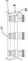
- LCDLMLiquid crystal light spatial modulator
- the liquid crystal light spatial modulator 3has a plurality of liquid crystals 31 therein, and when at least one pixel 11 on the self-luminous display 1 emits an incident light beam, as shown in FIG. 3B, the contact can be further changed.
- the driving voltage on the liquid crystal 31 of the light beam incident on the at least one pixel 11is such that the light direction of the light beam incident on the pixel 11 can achieve a collimating effect (the control device used to change the liquid crystal phase by changing the driving voltage on the liquid crystal 31) For the use of technology, so no additional instructions).
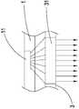
- the planar ultra-lens lens 4includes a plurality of regions 41 having bumps, and when operated, as shown in FIG. 4B, at least one of the pixels 11 is incident on a light beam.
- 41allows the direction of the light to achieve a collimation effect (and the planar super-lens 4 allows the light to move in different directions is a conventional technique, so no additional explanation), and the flat meta-lens also refers to the nano-convex
- the metasurface formed by the grainhas the function of refraction and changing the direction of the collimated light.
- the collimated light direction changing elementis a micro lens, a liquid crystal light spatial modulator (LCSLM) or a flat meta-lens, wherein different types of collimated light direction changing elements are described below. :
- Microlens(mircrolens):
- LCDLMLiquid crystal light spatial modulator
- liquid crystal light spatial modulator 3has the same structure as that of FIG. 3A, and has a plurality of liquid crystals 31 therein, and the operation principle for adjusting the direction of the collimated light is to change the contact between the two pixels.
- a driving voltage on the liquid crystal 31 of the light beamto cause at least two beams of the collimated effect to change direction to overlap to produce a focus of the virtual image;
- the collimating elementuses a microlens, and the collimating light direction changing element can use a microlens, a liquid crystal spatial modulator (LCSLM) or a flat meta-lens. .
- LCDMSLMliquid crystal spatial modulator
- the collimating elementuses a liquid crystal light spatial modulator (LCSLM), and the collimating light direction changing element can use the same liquid crystal optical spatial modulator (LCSLM).
- LCDSLMliquid crystal light spatial modulator
- the collimating elementuses a flat meta-lens, and the collimating light direction changing element can use the same flat meta-lens.
- the collimating elementuses a flat meta-lens, and the collimating light direction changing element can use a microlens, a liquid crystal spatial modulator (LCSLM) or a planar super-lens ( Flat meta-lens).
- LCDMSLMliquid crystal spatial modulator
- Flat meta-lensFlat meta-lens
- the collimating element usedis a microlens 2
- the collimated light direction changing elementis a liquid crystal optical spatial modulator 3, wherein when the microlens 2 is capable of two of the self-luminous display 1
- the liquid crystal 31 of the liquid crystal light spatial modulator 3is adjusted to adjust the collimated light direction of the light beam of one or more of the pixels 11 for the two pixels 11
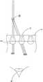
- the imagecan be extended and merged into a virtual image 51.
- the phase of the liquid crystal 31can be adjusted to change the direction of the collimated light, so that the images of the two pixels 11 can be overlapped and merged into another position.
- the phase of the liquid crystal 31can be continuously adjusted by the above method, so that the eye 6 can see a plurality of consecutive virtual images to achieve multiple depth of field imaging. .
- the microlens 2can be directly collimated and the collimated light direction can be adjusted. However, different microlenses can be preset to adjust the collimated light direction by different processes, so as shown in FIG. 6A, two different microlenses 2 are shown. After collimating, the two beams that have achieved the collimation effect are overlapped to generate the focus of the virtual image 53. However, if the focus of the other virtual image is to be formed, as shown in FIG. 6B, the other microlens 2 is transmitted through The beams that originally achieved the collimating effect by the microlens 2 overlap and produce the focus of the other virtual image 54.
- the present inventionis capable of overlapping beams emitted by two or more pixels and generating focus at different positions, so that the output image exhibits multiple depth of field imaging effects, and the pixel refers to a single pixel or A group of pixels containing several pixels.
- the liquid crystal light spatial modulator of the present inventioncan directly adjust the direction of the collimated light, so that the beams emitted by the two pixels can be overlapped to produce focus at different positions without moving the pixel position, thus saving The extra cost of using other optical components.
Landscapes
- Physics & Mathematics (AREA)
- General Physics & Mathematics (AREA)
- Optics & Photonics (AREA)
- Engineering & Computer Science (AREA)
- Microelectronics & Electronic Packaging (AREA)
- Nonlinear Science (AREA)
- Power Engineering (AREA)
- Condensed Matter Physics & Semiconductors (AREA)
- Computer Hardware Design (AREA)
- Liquid Crystal (AREA)
- Devices For Indicating Variable Information By Combining Individual Elements (AREA)
- Electroluminescent Light Sources (AREA)
Abstract
Description
Translated fromChinese本发明关于一种具有多重景深显像的近眼显示方法,特别是指一种能够使任两个画素所发出的光束交迭而产生不同位置聚焦,以使输出的影像能够呈现多重景深的近眼显示方法。The invention relates to a near-eye display method with multiple depth of field imaging, in particular to a near-eye display capable of overlapping beams emitted by any two pixels to generate different positions of focus so that the output image can exhibit multiple depth of fields. method.
因应现代社会对即时资讯的需求增高,随选资讯的传递备受重视。近眼显示器由于具有可携性,并结合电子装置可随时更新并传递图像、色彩或文字,因此为可携型个人资讯装置的一个很好的选择。早期近眼显示器多为军事或政府用途。近来有厂商看到商机,将近眼显示器引入家用。此外,娱乐相关业者也看中这块市场的潜力,例如家用游乐器及游乐器软体相关厂商已有投入研发。In response to the increasing demand for instant information in modern society, the delivery of on-demand information has received much attention. The near-eye display is a good choice for portable personal information devices because of its portability and the ability to update and deliver images, colors or text at any time in conjunction with electronic devices. Early near-eye displays were mostly military or government use. Recently, some manufacturers have seen business opportunities and introduced near-eye displays to homes. In addition, entertainment-related industry also sees the potential of this market, such as home game instruments and game software related manufacturers have invested in research and development.
目前近眼显示器(NED)系包括了头戴式显示器(HMD),其可将影像直接投射至观看者的眼睛中,这类显示器可藉由合成虚拟大幅面显示表面来克服其他行动显示形式因素所提供的有限荧幕尺寸,或可用于虚拟或扩增实境应用。Currently, the near-eye display (NED) includes a head-mounted display (HMD) that projects images directly into the viewer's eyes. This type of display can overcome other action display form factors by synthesizing a virtual large-format display surface. Available in a limited screen size, or for virtual or augmented reality applications.
而该近眼显示器能再细分为两大类别:沉浸式显示器和透视显示器。其中在虚拟实境(VR)环境中可采用沉浸式显示器以使用合成呈现影像来完全地涵盖使用者的视野。而在扩增实境(AR)的应用则能够采用透视显示器,其中可在实体环境的使用者的视野中重迭文字、其他合成注解、或影像。在显示技术方面,AR应用需要半透明显示器(例如,藉由光学或电光方法来实现),使得可以近眼显示器来同时地观看实体世界。The near-eye display can be subdivided into two major categories: immersive displays and see-through displays. An immersive display can be employed in a virtual reality (VR) environment to fully encompass the user's field of view using a composite rendered image. In augmented reality (AR) applications, a see-through display can be used in which text, other synthetic annotations, or images can be overlaid in the field of view of the user in a physical environment. In terms of display technology, AR applications require a translucent display (eg, by optical or electro-optic methods) such that a near-eye display can be used to simultaneously view the physical world.
但由于人的肉眼不能调焦(聚焦)于置放在近距离(例如,当使用者正戴着眼镜时,阅读用放大镜的透镜到使用者的眼睛之间的距离)内的物件的事实而难以建构。因此,近眼显示器则必须经过调整来使观看者能舒适的使用,否则将会导致发生失焦等影响使用的情况发生,然而传统则是使用复杂且笨重的光学元件来进行调整,但由于近眼显示器大多是必须直接配戴于观看者的头上,故太过于笨重的近眼显示器则往往无法被消费者所接受。However, since the human eye cannot focus (focus) on the fact that the object is placed at a close distance (for example, when the user is wearing glasses, reading the distance between the lens of the magnifying glass and the user's eyes). Difficult to construct. Therefore, the near-eye display must be adjusted to make the viewer comfortable to use, otherwise it will lead to the occurrence of defocus, etc., but the traditional use of complex and cumbersome optical components to adjust, but because of the near-eye display Most of them must be worn directly on the viewer's head, so too clunky near-eye displays are often not acceptable to consumers.
因此,为了克服上述问题,若能够使任两个或两个以上的画素所发出的光束交迭而产生聚焦,以使输出的影像能够清晰呈现,如此将不需使用笨重的光学元件,且亦能够节省使用笨重的光学元件所产生的额外成本,如此应为一最佳解决方案。Therefore, in order to overcome the above problem, if the beams emitted by any two or more pixels can be overlapped to generate focus so that the output image can be clearly displayed, it is not necessary to use bulky optical components, and The ability to save on the extra cost of using bulky optics should be an optimal solution.
发明内容Summary of the invention
本发明的目的在于提供一种具有多重景深显像的近眼显示方法,其能节约成本,提高显示效果,能够使任两个画素所发出的光束交迭而产生不同位置聚焦,以使输出的影像能够呈现多重景深。It is an object of the present invention to provide a near-eye display method with multiple depth of field imaging, which can save cost and improve display effect, and can overlap beams emitted by any two pixels to generate different positions of focus to make an output image. Ability to present multiple depths of field.
为达成上述目的,本发明公开了一种具有多重景深显像的近眼显示方法,其特征在于该方法为:In order to achieve the above object, the present invention discloses a near-eye display method with multiple depth of field imaging, which is characterized in that:
能够透过一自发光显示器上的一个或多个画素对一准直元件发出光源照射,以使穿过该准直元件的入射光能够达到准直效果形成准直光;以及Illuminating a collimating element with a light source through one or more pixels on a self-illuminating display such that incident light passing through the collimating element can achieve a collimating effect to form collimated light;
而至少一个准直光方向改变元件能够设置于该准直元件的光束的光线方向路径上,用以改变至少两个画素所发出的准直光方向,以能够于不同位置交迭而产生聚焦并改变景深。The at least one collimated light direction changing component can be disposed on the light directional path of the light beam of the collimating component to change the collimated light direction emitted by the at least two pixels to be able to overlap at different positions to generate focus and Change the depth of field.
其中,该自发光显示器所使用的显示技术为有机发光二极体、微发光二极体、量子点或雷射的主动发光源。The display technology used in the self-luminous display is an organic light emitting diode, a micro light emitting diode, a quantum dot or a laser active light source.
其中,该自发光显示器为透明显示器或非透明显示器。Wherein, the self-luminous display is a transparent display or a non-transparent display.
其中,该准直元件为微透镜、平面超颖透镜或液晶光空间调变器。Wherein, the collimating element is a microlens, a planar super-lens lens or a liquid crystal optical spatial modulator.
其中,该平面超颖透镜能够达到屈光镜的效果,用以使光线方向能够达到准直效果。Among them, the planar super-lens lens can achieve the effect of the diopter, so that the direction of the light can achieve the collimation effect.
其中,该液晶光空间调变器具有液晶,能够藉由改变电压调整液晶排列,以使每一个画素的入射光的光线方向能够达到准直效果。Wherein, the liquid crystal light spatial modulator has liquid crystal, and the liquid crystal alignment can be adjusted by changing the voltage so that the light direction of the incident light of each pixel can achieve the collimation effect.
其中,该准直光方向改变元件为微透镜、平面超颖透镜或液晶光空间调变器。Wherein, the collimated light direction changing element is a microlens, a planar super-lens lens or a liquid crystal optical spatial modulator.
其中,该微透镜用以使至少两个经准直后的光束系能够交迭而产生聚焦。Wherein, the microlens is used to enable at least two collimated beam systems to overlap to produce focus.
其中,该平面超颖透镜包含有多个具有凸粒的区域用以使至少两个经准直后的光束系能够交迭而产生聚焦。Wherein, the planar super-lens lens comprises a plurality of regions having convex particles for enabling at least two collimated beam systems to overlap to produce focusing.
其中,透过另外两个不同具有凸粒的区域,来使至少两个经准直后的光束于不同位置产生交迭,以达到不同位置交迭而产生聚焦的多重景深显像。Wherein, through the other two different regions having convex ridges, at least two collimated beams are overlapped at different positions to achieve overlapping multiple depth of field images in which different positions overlap.
其中,透过其中一个相同、另外一个不同具有凸粒的区域,来使至少两个经准直后的光束于不同位置产生交迭,以达到不同位置交迭而产生聚焦的多重景深显像。Wherein, through one of the same and another different regions having convex ridges, at least two collimated beams are overlapped at different positions to achieve multiple depth-of-field visualizations in which different positions overlap to produce focus.
其中,该液晶光空间调变器具有液晶,能够藉由改变电压调整液晶排列,以改变经准直后的光束方向,来使至少两个所达到准直效果的光束系能够交迭而产生聚焦。Wherein, the liquid crystal light spatial modulator has a liquid crystal, and the liquid crystal alignment can be adjusted by changing the voltage to change the collimated beam direction, so that at least two collimated beam systems can overlap to generate focus. .
其中,能够改变至少两个液晶上的驱动电压,以使两个所经准直后的光束于不同位置产生交迭,来达到不同位置交迭而产生聚焦的多重景深显像。Wherein, the driving voltages on the at least two liquid crystals can be changed, so that the two collimated light beams are overlapped at different positions to achieve overlapping multiple depth of field images in which different positions overlap.
其中,能够改变至少一个不同的液晶上的驱动电压,以使两个所经准直后的光束于不同位置产生交迭,来达到不同位置交迭而产生聚焦的多重景深显像。Wherein, the driving voltage on at least one different liquid crystal can be changed, so that the two collimated beams are overlapped at different positions to achieve overlapping multiple depth of field images in which different positions overlap.
其中,该画素指单一画素或是包含有数个画素的画素群。The pixel refers to a single pixel or a pixel group containing a plurality of pixels.
通过上述内容,本发明能实现如下技术效果:Through the above, the present invention can achieve the following technical effects:
1.本发明系能够使两个或两个以上的画素所发出的光束交迭而于不同位置产生聚焦,以使输出的影像呈现多重景深显像的效果,而上述画素系指单一画素或是包含有数个画素的画素群。1. The present invention is capable of overlapping beams emitted by two or more pixels and generating focus at different positions, so that the output image exhibits multiple depth of field imaging effects, and the pixel refers to a single pixel or A group of pixels containing several pixels.
2.本发明的液晶光空间调变器系能够直接调整准直光方向,因此不须移动画素位置,即可使两个画素所发出的光束交迭而于不同位置产生聚焦,如此将能够节省使用其他光学元件所产生的额外成本。2. The liquid crystal light spatial modulator of the present invention can directly adjust the direction of the collimated light, so that the beams emitted by the two pixels can be overlapped to produce focus at different positions without moving the pixel position, thus saving The extra cost of using other optical components.
图1:本发明具有多重景深显像的近眼显示方法的流程示意图。FIG. 1 is a schematic flow chart of a near-eye display method with multiple depth of field imaging according to the present invention.
图2A:本发明具有多重景深显像的近眼显示方法的第一实施架构示意图。2A is a schematic view showing a first implementation architecture of a near-eye display method with multiple depth of field imaging according to the present invention.
图2B:本发明具有多重景深显像的近眼显示方法的第一实施应用示意图。2B is a schematic view showing a first implementation application of the near-eye display method with multiple depth of field imaging of the present invention.
图3A:本发明具有多重景深显像的近眼显示方法的第二实施架构示意图。FIG. 3A is a schematic diagram showing a second implementation architecture of a near-eye display method with multiple depth of field imaging according to the present invention.
图3B:本发明具有多重景深显像的近眼显示方法的第二实施应用示意图。FIG. 3B is a schematic view showing a second implementation application of the near-eye display method with multiple depth of field imaging of the present invention.
图4A:本发明具有多重景深显像的近眼显示方法的第三实施架构示意图。4A is a schematic diagram of a third implementation architecture of a near-eye display method with multiple depth of field imaging of the present invention.
图4B:本发明具有多重景深显像的近眼显示方法的第三实施应用示意图。4B is a schematic view showing a third implementation application of the near-eye display method with multiple depth of field imaging of the present invention.
图5A:本发明具有多重景深显像的近眼显示方法的多重景深示意图。FIG. 5A is a schematic diagram showing multiple depth of field of the near-eye display method with multiple depth of field imaging of the present invention.
图5B:本发明具有多重景深显像的近眼显示方法的多重景深示意图。FIG. 5B is a schematic diagram showing multiple depth of field of the near-eye display method with multiple depth of field imaging of the present invention.
图6A:本发明具有多重景深显像的近眼显示方法的另一实施多重景深示意图。Fig. 6A is a schematic view showing another embodiment of the near-eye display method with multiple depth of field imaging of the present invention.
图6B:本发明具有多重景深显像的近眼显示方法的另一实施多重景深示意图。6B is a schematic diagram showing multiple embodiments of the near-eye display method with multiple depth of field imaging of the present invention.
有关于本发明其他技术内容、特点与功效,在以下配合参考图式的较佳实施例的详细说明中,将可清楚的呈现。Other details, features, and advantages of the present invention will be apparent from the following description of the preferred embodiments.
请参阅图1,为本发明具有多重景深显像的近眼显示方法的流程示意图,由图中可知,其步骤为:Please refer to FIG. 1 , which is a schematic flowchart of a near-eye display method with multiple depth of field imaging according to the present invention. As shown in the figure, the steps are as follows:
(1)能够透过一自发光显示器上的一个或多个画素对一准直元件发出光源照射,以使穿过该准直元件的入射光能够达到准直效果101;以及(1) illuminating a collimating element with a light source through one or more pixels on a self-illuminating display such that incident light passing through the collimating element can achieve a
(2)而至少一个准直光方向改变元件能够设置于该准直元件的光束的光线方向路径上,用以改变至少两个画素所发出的准直光方向,以能够于不同位置交迭而产生聚焦并改变景深102。(2) at least one of the collimated light direction changing elements can be disposed on the light direction path of the light beam of the collimating element for changing the collimated light direction emitted by the at least two pixels to be able to overlap at different positions. Focus is produced and the depth of
而上述流程中,所使用的自发光显示器1所使用的显示技术系为能够自主发光的显示器,而该自发光显示器1系能够透明显示器或是非透明显示器,且该自发光显示器的类型能够为有机发光二极体(OLED)、微发光二极体(micro LED)、量子点(Quantum dot)、雷射或其他任何形式的主动发光源。In the above process, the display technology used in the self-
而该准直元件系为微透镜(mircrolens)、液晶光空间调变器(Liquid Crystal Spatial Light Modulator,LCSLM)或是平面超颖透镜(flat meta-lens),其中不同类型的准直元件说明如下:The collimating component is a micro lens, a liquid crystal spatial light modulator (LCSLM) or a flat meta-lens, wherein different types of collimating components are described below. :
(1)微透镜(mircrolens):(1) Microlens (mircrolens):
如图2A所示,该微透镜2系位于该自发光显示器1所发出光束的光线方向行进的路径上,而当运作时,如图2B所示,用以能够让该自发光显示器1上的至少一个画素11所入射的光束的光线方向能够达到准直效果。As shown in FIG. 2A, the
(2)液晶光空间调变器(LCSLM):(2) Liquid crystal light spatial modulator (LCSLM):
如图3A所示,该液晶光空间调变器3内具有数个液晶31,而当该自发光显示器1上的至少一个画素11发出入射的光束时,如图3B所示,能够进一步改变接触到至少一个画素11所入射的光束的液晶31上的驱动电压来使画素11所入射的光束的光线方向能够达到准直效果(而改变液晶31上的驱动电压来改变液晶相位所使用的控制设备为习用技术,故不额外说明)。As shown in FIG. 3A, the liquid crystal light
(3)平面超颖透镜(flat meta-lens):(3) Flat meta-lens:
如图4A所示,该平面超颖透镜4系包含有多个具有凸粒的区域41,而当运作时,如图4B所示,其中至少一个画素11所入射的光束能够透过其中一个区域41使光线方向能够达到准直效果(而平面超颖透镜4让光线朝不同方向前进是习用技术,故不额外说明),而该平面超颖透镜(flat meta-lens)亦即指奈米凸粒形成的超颖平面(metasurface),具有屈光与改变准直光方向的功能。As shown in FIG. 4A, the planar
而该准直光方向改变元件系为微透镜(mircrolens)、液晶光空间调变器(LCSLM)或是平面超颖透镜(flat meta-lens),其中不同类型的准直光方向改变元件说明如下:The collimated light direction changing element is a micro lens, a liquid crystal light spatial modulator (LCSLM) or a flat meta-lens, wherein different types of collimated light direction changing elements are described below. :
(1)微透镜(mircrolens):(1) Microlens (mircrolens):
(a)其中该微透镜2的结构与图2A相同,用以使至少两个达到准直效果的光束系能够交迭而产生虚像的焦点;(a) wherein the structure of the
(b)其中透过两个不同的微透镜2,来使两个所达到准直效果的光束产生交迭,并再使用另一个微透镜2于不同位置交迭而产生聚焦的多重景深显像。(b) wherein two
(2)液晶光空间调变器(LCSLM):(2) Liquid crystal light spatial modulator (LCSLM):
(a)其中该液晶光空间调变器3的结构与图3A相同,内具有数个液晶31,其用于调整准直光方向的运作原理则是来改变接触到其中两个画素所入射的光束的液晶31上的驱动电压,来使至少两个所达到准直效果的光束改变方向达到交迭而产生虚像的焦点;(a) wherein the liquid crystal light
(b)其中能够改变至少两个不同的液晶31上的驱动电压,以使两个所达到准直效果的光束于不同位置产生交迭,来达到不同位置交迭而产生聚焦的多重景深显像;(b) wherein the driving voltages on the at least two different
(c)其中能够使一个液晶31上的驱动电压不改变,但改变至少另一个不同的液晶31上的驱动电压,则能使两个所达到准直效果的光束于不同位置产生交迭,来达到不同位置交迭而产生聚焦的多重景深显像。(c) wherein the driving voltage on one
(3)平面超颖透镜(flat meta-lens):(3) Flat meta-lens:
(a)其中该平面超颖透镜4的结构与图4A相同,用以使至少两个达到准直效果的光束系能够交迭而产生虚像的焦点;(a) wherein the structure of the
(b)其中透过两个不同的具有凸粒的区域41,来使两个所达到准直效果的光束于不同位置产生交迭,以达到不同位置交迭而产生聚焦的多重景深显像;(b) wherein two different regions having convex lobes are used to cause the two collimated beams to overlap at different positions to achieve multiple depth-of-field imaging in which different positions overlap to produce focus;
(c)其中透过其中一个相同、另外一个不同的具有凸粒的区域41,来使两个所达到准直效果的光束于不同位置产生交迭,以达到不同位置交迭而产生聚焦的多重景深显像。(c) wherein, through one of the same and another
而当实际要产生多重景深显像时,能够搭配不同的准直元件及不同的准直光方向改变元件,搭配样态如下:When it is actually necessary to generate multiple depth of field imaging, it can be matched with different collimating components and different collimated light direction changing components, and the matching state is as follows:
(1)准直元件使用微透镜(mircrolens),而该准直光方向改变元件能够使用微透镜(mircrolens)、液晶光空间调变器(LCSLM)或是平面超颖透镜(flat meta-lens)。(1) The collimating element uses a microlens, and the collimating light direction changing element can use a microlens, a liquid crystal spatial modulator (LCSLM) or a flat meta-lens. .
(2)准直元件使用液晶光空间调变器(LCSLM),而该准直光方向改变元件能够使用同一个液晶光空间调变器(LCSLM)。(2) The collimating element uses a liquid crystal light spatial modulator (LCSLM), and the collimating light direction changing element can use the same liquid crystal optical spatial modulator (LCSLM).
(3)准直元件使用平面超颖透镜(flat meta-lens),而该准直光方向改变元件能够使用同一个平面超颖透镜(flat meta-lens)。(3) The collimating element uses a flat meta-lens, and the collimating light direction changing element can use the same flat meta-lens.
(4)准直元件使用平面超颖透镜(flat meta-lens),而该准直光方向改变元件能够使用微透镜(mircrolens)、液晶光空间调变器(LCSLM)或是平面超颖透镜(flat meta-lens)。(4) The collimating element uses a flat meta-lens, and the collimating light direction changing element can use a microlens, a liquid crystal spatial modulator (LCSLM) or a planar super-lens ( Flat meta-lens).
如图5A所示,所使用的准直元件为微透镜2,而该准直光方向改变元件为液 晶光空间调变器3,其中当微透镜2能够将该自发光显示器1上的两个画素11所入射的光束的光线方向能够达到准直效果后,再透液晶光空间调变器3的液晶31调整其中一个或多个画素11的光束的准直光方向,以于两个画素11的影像能够延伸重迭汇合为一虚像51,之后如图5B所示,则能够调整液晶31的相位以改变准直光方向,将能够使两个画素11的影像能够重迭汇合于另一位置,以形成另一个虚像52来使景深拉长,因此透过上述做法,则能够不断调整液晶31的相位,来让人眼6能够看到多个连续的虚像,以达到多重景深显像的目的。As shown in FIG. 5A, the collimating element used is a
另外,亦能够使用单一元件进行准直及调整准直光方向,说明如下:In addition, it is also possible to use a single component to collimate and adjust the collimated light direction, as explained below:
(1)能够将该微透镜2直接进行准直及调整准直光方向,然而不同的微透镜经过制程能够预设调整准直光方向不同,故如图6A所示,两个不同微透镜2经由准直后,再使两个所达到准直效果的光束交迭而产生虚像53的焦点,然而若是要形成另一个虚像的焦点,则如图6B所示,透过另一个微透镜2与原本由微透镜2达到准直效果的光束进行交迭并产生另一个虚像54的焦点。(1) The
(2)亦能够仅使用液晶光空间调变器3或是平面超颖透镜4同时进行准直及调整准直光方向,而液晶光空间调变器3的液晶31更能够直接改变液晶31上的驱动电压来调整准直光方向以形成不同位置的虚像的焦点,然而平面超颖透镜4则必须透过多个不同具有凸粒的区域41来形成不同位置的虚像的焦点。(2) It is also possible to simultaneously collimate and adjust the collimated light direction using only the liquid crystal light
本发明所提供的具有多重景深显像的近眼显示方法,与其他习用技术相互比较时,其优点如下:The near-eye display method with multiple depth of field imaging provided by the present invention has the following advantages when compared with other conventional technologies:
1.本发明系能够使两个或两个以上的画素所发出的光束交迭而于不同位置产生聚焦,以使输出的影像呈现多重景深显像的效果,而上述画素系指单一画素或是包含有数个画素的画素群。1. The present invention is capable of overlapping beams emitted by two or more pixels and generating focus at different positions, so that the output image exhibits multiple depth of field imaging effects, and the pixel refers to a single pixel or A group of pixels containing several pixels.
2.本发明的液晶光空间调变器系能够直接调整准直光方向,因此不须移动画素位置,即可使两个画素所发出的光束交迭而于不同位置产生聚焦,如此将能够节省使用其他光学元件所产生的额外成本。2. The liquid crystal light spatial modulator of the present invention can directly adjust the direction of the collimated light, so that the beams emitted by the two pixels can be overlapped to produce focus at different positions without moving the pixel position, thus saving The extra cost of using other optical components.
本发明已透过上所述的实施例揭露如上,然其并非用以限定本发明,任何熟悉此一技术领域具有通常知识者,在了解本发明前述的技术特征及实施例,并在不脱离本发明的精神和范围内,当可作些许的更动与润饰,因此本发明的专利保护范围须视本说明书所附的权利要求所界定者为准。The present invention has been disclosed above by the above-described embodiments, and is not intended to limit the present invention. Any one skilled in the art can understand the foregoing technical features and embodiments of the present invention without departing from the invention. In the spirit and scope of the present invention, the scope of the invention is to be determined by the appended claims.
Claims (15)
Translated fromChinesePriority Applications (13)
| Application Number | Priority Date | Filing Date | Title |
|---|---|---|---|
| US16/976,506US11927871B2 (en) | 2018-03-01 | 2018-03-01 | Near-eye displaying method capable of multiple depths of field imaging |
| KR1020207028341AKR20200127023A (en) | 2018-03-01 | 2018-03-01 | Near-eye display method capable of shooting multiple depths of field |
| PCT/CN2018/077715WO2019165620A1 (en) | 2018-03-01 | 2018-03-01 | Near eye display method capable of multi-depth of field imaging |
| CN201880090627.7ACN111837068A (en) | 2018-03-01 | 2018-03-01 | A near-eye display method with multiple depth-of-field imaging |
| JP2020568582AJP7195653B2 (en) | 2018-03-01 | 2018-03-01 | A near-eye display method that enables multiple depths of field images |
| EP18907507.0AEP3761102B1 (en) | 2018-03-01 | 2018-03-01 | Near eye display method capable of multi-depth of field imaging |
| TW108106943ATW201937234A (en) | 2018-03-01 | 2019-02-28 | Display component and display device |
| EP19760179.2AEP3761364A4 (en) | 2018-03-01 | 2019-03-01 | DISPLAY COMPONENT AND DISPLAY DEVICE |
| KR1020207028337AKR20200127235A (en) | 2018-03-01 | 2019-03-01 | Display assembly and display device |
| CN201980016537.8ACN111801803A (en) | 2018-03-01 | 2019-03-01 | Display components and display devices |
| JP2020568586AJP2021520523A (en) | 2018-03-01 | 2019-03-01 | Display assembly and display equipment |
| PCT/CN2019/076752WO2019166018A1 (en) | 2018-03-01 | 2019-03-01 | Display component and display device |
| US16/976,526US20210005681A1 (en) | 2018-03-01 | 2019-03-01 | Display assembly and display device |
Applications Claiming Priority (1)
| Application Number | Priority Date | Filing Date | Title |
|---|---|---|---|
| PCT/CN2018/077715WO2019165620A1 (en) | 2018-03-01 | 2018-03-01 | Near eye display method capable of multi-depth of field imaging |
Publications (1)
| Publication Number | Publication Date |
|---|---|
| WO2019165620A1true WO2019165620A1 (en) | 2019-09-06 |
Family
ID=67804822
Family Applications (2)
| Application Number | Title | Priority Date | Filing Date |
|---|---|---|---|
| PCT/CN2018/077715CeasedWO2019165620A1 (en) | 2018-03-01 | 2018-03-01 | Near eye display method capable of multi-depth of field imaging |
| PCT/CN2019/076752CeasedWO2019166018A1 (en) | 2018-03-01 | 2019-03-01 | Display component and display device |
Family Applications After (1)
| Application Number | Title | Priority Date | Filing Date |
|---|---|---|---|
| PCT/CN2019/076752CeasedWO2019166018A1 (en) | 2018-03-01 | 2019-03-01 | Display component and display device |
Country Status (7)
| Country | Link |
|---|---|
| US (2) | US11927871B2 (en) |
| EP (2) | EP3761102B1 (en) |
| JP (2) | JP7195653B2 (en) |
| KR (2) | KR20200127023A (en) |
| CN (2) | CN111837068A (en) |
| TW (1) | TW201937234A (en) |
| WO (2) | WO2019165620A1 (en) |
Cited By (1)
| Publication number | Priority date | Publication date | Assignee | Title |
|---|---|---|---|---|
| WO2021201965A1 (en)* | 2020-04-01 | 2021-10-07 | Massachusetts Institute Of Technology | Meta-optics-based systems and methods for ocular applications |
Families Citing this family (16)
| Publication number | Priority date | Publication date | Assignee | Title |
|---|---|---|---|---|
| US11927871B2 (en) | 2018-03-01 | 2024-03-12 | Hes Ip Holdings, Llc | Near-eye displaying method capable of multiple depths of field imaging |
| JP7582675B2 (en) | 2019-11-06 | 2024-11-13 | ヒーズ アイピー ホールディングス エルエルシー | System and method for displaying objects with depth |
| CN110910769B (en)* | 2019-11-29 | 2022-04-08 | 京东方科技集团股份有限公司 | Virtual display device and preparation method and control method thereof |
| US12298512B2 (en) | 2020-06-19 | 2025-05-13 | Oomii Inc. | Image display systems for eyebox expansion and methods of making the same |
| CN111864119B (en)* | 2020-07-31 | 2024-01-19 | 京东方科技集团股份有限公司 | Display device and near-to-eye display apparatus |
| TWI862393B (en) | 2020-08-14 | 2024-11-11 | 美商海思智財控股有限公司 | Head wearable virtual image module for superimposing virtual image on real-time image |
| CN114616511A (en) | 2020-09-03 | 2022-06-10 | 海思智财控股有限公司 | System and method for improving binocular vision |
| WO2022059152A1 (en)* | 2020-09-17 | 2022-03-24 | シャープ株式会社 | Display device and method for manufacturing display device |
| WO2022072565A1 (en) | 2020-09-30 | 2022-04-07 | Hes Ip Holdings, Llc | Virtual image display system for virtual reality and augmented reality devices |
| JP2022097093A (en)* | 2020-12-18 | 2022-06-30 | ソニーセミコンダクタソリューションズ株式会社 | Semiconductor device |
| US12260580B2 (en) | 2021-02-08 | 2025-03-25 | Oomii Inc. | System and method for enhancing visual acuity of head wearable displays |
| KR20220149878A (en) | 2021-04-30 | 2022-11-09 | 삼성디스플레이 주식회사 | Display device |
| US20230201067A1 (en)* | 2021-06-11 | 2023-06-29 | Hes Ip Holdings, Llc | Systems and methods for improving vision of a viewer's eye with impaired retina |
| TWI832581B (en) | 2021-12-15 | 2024-02-11 | 財團法人工業技術研究院 | Head-mounted augmented reality stereo vision optical film on glass |
| TWI807535B (en) | 2021-12-15 | 2023-07-01 | 財團法人工業技術研究院 | Head-mounted augmented reality stereo vision optical film on glass |
| WO2024034502A1 (en)* | 2022-08-09 | 2024-02-15 | ソニーセミコンダクタソリューションズ株式会社 | Light-emitting device and electronic equipment |
Citations (6)
| Publication number | Priority date | Publication date | Assignee | Title |
|---|---|---|---|---|
| CN105739094A (en)* | 2014-12-11 | 2016-07-06 | 北京邮电大学 | Near-eye display method based on lens array |
| CN106292240A (en)* | 2016-09-05 | 2017-01-04 | 京东方科技集团股份有限公司 | Holographic display and display packing thereof |
| CN106526864A (en)* | 2017-01-05 | 2017-03-22 | 京东方科技集团股份有限公司 | Display device and display method |
| CN106873161A (en)* | 2017-03-02 | 2017-06-20 | 上海天马微电子有限公司 | Display device and near-to-eye wearable equipment |
| CN107561702A (en)* | 2016-07-01 | 2018-01-09 | 成都理想境界科技有限公司 | A kind of near-eye display system, virtual reality device and augmented reality equipment |
| WO2018013307A1 (en)* | 2016-06-21 | 2018-01-18 | Ntt Docomo, Inc. | An illuminator for a wearable display |
Family Cites Families (38)
| Publication number | Priority date | Publication date | Assignee | Title |
|---|---|---|---|---|
| JP3136178B2 (en) | 1991-10-09 | 2001-02-19 | 株式会社リコー | Display device |
| JPH11234705A (en) | 1998-02-17 | 1999-08-27 | Matsushita Electric Ind Co Ltd | 3D display device |
| JP2002090704A (en)* | 2000-09-18 | 2002-03-27 | Katsumi Yoshino | Read device for liquid crystal display panel |
| JP4491948B2 (en) | 2000-10-06 | 2010-06-30 | ソニー株式会社 | Device mounting method and image display device manufacturing method |
| SG143946A1 (en) | 2001-02-19 | 2008-07-29 | Semiconductor Energy Lab | Light emitting device and method of manufacturing the same |
| JP2005175417A (en) | 2003-07-28 | 2005-06-30 | Ricoh Co Ltd | Light emitting element array, optical writing unit, and image forming apparatus |
| JP2007027157A (en) | 2005-07-12 | 2007-02-01 | Akita Denshi Systems:Kk | LIGHT EMITTING DIODE DEVICE, ITS MANUFACTURING METHOD, AND LIGHTING DEVICE |
| JP4839795B2 (en)* | 2005-11-24 | 2011-12-21 | ソニー株式会社 | 3D display device |
| US7782278B2 (en)* | 2006-12-14 | 2010-08-24 | Himax Technologies Limited | Intra-pixel convolution for AMOLED |
| JP2011145607A (en) | 2010-01-18 | 2011-07-28 | Sony Corp | Head mount display |
| CN102629667B (en) | 2012-04-25 | 2015-03-25 | 上海大学 | Silicon substrate top emission organic light emitting microdisplay and method for producing same |
| US20130285885A1 (en) | 2012-04-25 | 2013-10-31 | Andreas G. Nowatzyk | Head-mounted light-field display |
| US9841537B2 (en) | 2012-07-02 | 2017-12-12 | Nvidia Corporation | Near-eye microlens array displays |
| US9860522B2 (en) | 2012-08-04 | 2018-01-02 | Paul Lapstun | Head-mounted light field display |
| WO2014031655A1 (en) | 2012-08-20 | 2014-02-27 | Frattalone John | Modular video and lighting displays |
| US9442460B2 (en) | 2012-10-31 | 2016-09-13 | Lg Display Co., Ltd. | Digital hologram display device |
| WO2014100753A1 (en) | 2012-12-21 | 2014-06-26 | Reald Inc. | Superlens component for directional display |
| JP6337433B2 (en) | 2013-09-13 | 2018-06-06 | セイコーエプソン株式会社 | Head-mounted display device and method for controlling head-mounted display device |
| KR102053440B1 (en)* | 2013-09-26 | 2020-01-08 | 엘지디스플레이 주식회사 | Organic Light Emitting Diode Display Having High Aperture Ratio And Method For Manufacturing The Same |
| GB2525862A (en)* | 2014-05-06 | 2015-11-11 | Univ Bedfordshire | Lens array and imaging device |
| JP6305855B2 (en) | 2014-07-11 | 2018-04-04 | オリンパス株式会社 | Image display device |
| GB201413578D0 (en) | 2014-07-31 | 2014-09-17 | Infiniled Ltd | A colour iled display on silicon |
| GB201418772D0 (en) | 2014-10-22 | 2014-12-03 | Infiniled Ltd | Display |
| KR102312576B1 (en)* | 2014-11-05 | 2021-10-14 | 엘지디스플레이 주식회사 | Organic electroluminescence display device and method for fabricating thereof |
| WO2016163231A1 (en) | 2015-04-09 | 2016-10-13 | シャープ株式会社 | Spectacle type display device |
| EP3353578B1 (en)* | 2015-09-23 | 2021-01-20 | OSRAM Opto Semiconductors GmbH | Collimating metalenses and technologies incorporating the same |
| FR3044467B1 (en) | 2015-11-26 | 2018-08-10 | Commissariat A L'energie Atomique Et Aux Energies Alternatives | LIGHT DALLE AND METHOD FOR MANUFACTURING SUCH LIGHT SLAB |
| CN105449125B (en) | 2015-12-03 | 2018-11-09 | 东南大学 | A kind of si-based quantum dot display and preparation method thereof |
| TWI696847B (en) | 2016-01-28 | 2020-06-21 | 中強光電股份有限公司 | Head-mounted display |
| US9964767B2 (en) | 2016-03-03 | 2018-05-08 | Google Llc | Display with reflected LED micro-display panels |
| CN107561697B (en)* | 2016-07-01 | 2019-04-30 | 成都理想境界科技有限公司 | Near-eye display system, virtual reality device and augmented reality equipment |
| CN105911791A (en)* | 2016-07-04 | 2016-08-31 | 京东方科技集团股份有限公司 | Display panel and display device |
| CN107664840A (en)* | 2016-07-28 | 2018-02-06 | 中强光电股份有限公司 | Head-mounted display device |
| CN106057843B (en) | 2016-08-05 | 2019-04-30 | 京东方科技集团股份有限公司 | Transparent display panel, transparent display device, and manufacturing method of transparent display panel |
| TWI607243B (en)* | 2016-08-09 | 2017-12-01 | Tai Guo Chen | Display adjustment method for near-eye display |
| CN110376742A (en) | 2017-03-23 | 2019-10-25 | 华为机器有限公司 | Near-eye display and near-eye display system |
| CN106932916B (en)* | 2017-05-04 | 2019-10-01 | 鲁东大学 | A kind of dual-beam super-resolution focus method using Meta Materials lens |
| US11927871B2 (en) | 2018-03-01 | 2024-03-12 | Hes Ip Holdings, Llc | Near-eye displaying method capable of multiple depths of field imaging |
- 2018
- 2018-03-01USUS16/976,506patent/US11927871B2/enactiveActive
- 2018-03-01CNCN201880090627.7Apatent/CN111837068A/enactivePending
- 2018-03-01EPEP18907507.0Apatent/EP3761102B1/enactiveActive
- 2018-03-01JPJP2020568582Apatent/JP7195653B2/enactiveActive
- 2018-03-01KRKR1020207028341Apatent/KR20200127023A/ennot_activeCeased
- 2018-03-01WOPCT/CN2018/077715patent/WO2019165620A1/ennot_activeCeased
- 2019
- 2019-02-28TWTW108106943Apatent/TW201937234A/enunknown
- 2019-03-01JPJP2020568586Apatent/JP2021520523A/enactivePending
- 2019-03-01CNCN201980016537.8Apatent/CN111801803A/enactivePending
- 2019-03-01USUS16/976,526patent/US20210005681A1/ennot_activeAbandoned
- 2019-03-01KRKR1020207028337Apatent/KR20200127235A/ennot_activeCeased
- 2019-03-01WOPCT/CN2019/076752patent/WO2019166018A1/ennot_activeCeased
- 2019-03-01EPEP19760179.2Apatent/EP3761364A4/ennot_activeWithdrawn
Patent Citations (6)
| Publication number | Priority date | Publication date | Assignee | Title |
|---|---|---|---|---|
| CN105739094A (en)* | 2014-12-11 | 2016-07-06 | 北京邮电大学 | Near-eye display method based on lens array |
| WO2018013307A1 (en)* | 2016-06-21 | 2018-01-18 | Ntt Docomo, Inc. | An illuminator for a wearable display |
| CN107561702A (en)* | 2016-07-01 | 2018-01-09 | 成都理想境界科技有限公司 | A kind of near-eye display system, virtual reality device and augmented reality equipment |
| CN106292240A (en)* | 2016-09-05 | 2017-01-04 | 京东方科技集团股份有限公司 | Holographic display and display packing thereof |
| CN106526864A (en)* | 2017-01-05 | 2017-03-22 | 京东方科技集团股份有限公司 | Display device and display method |
| CN106873161A (en)* | 2017-03-02 | 2017-06-20 | 上海天马微电子有限公司 | Display device and near-to-eye wearable equipment |
Non-Patent Citations (1)
| Title |
|---|
| See also references ofEP3761102A4* |
Cited By (3)
| Publication number | Priority date | Publication date | Assignee | Title |
|---|---|---|---|---|
| WO2021201965A1 (en)* | 2020-04-01 | 2021-10-07 | Massachusetts Institute Of Technology | Meta-optics-based systems and methods for ocular applications |
| US11206978B2 (en) | 2020-04-01 | 2021-12-28 | Massachusetts Institute Of Technology | Meta-optics-based systems and methods for ocular applications |
| US11850001B2 (en) | 2020-04-01 | 2023-12-26 | Massachusetts Institute Of Technology | Meta-optics-based systems and methods for ocular applications |
Also Published As
| Publication number | Publication date |
|---|---|
| US11927871B2 (en) | 2024-03-12 |
| EP3761102A1 (en) | 2021-01-06 |
| JP2021520523A (en) | 2021-08-19 |
| JP7195653B2 (en) | 2022-12-26 |
| CN111837068A (en) | 2020-10-27 |
| CN111801803A (en) | 2020-10-20 |
| EP3761364A1 (en) | 2021-01-06 |
| EP3761364A4 (en) | 2021-04-21 |
| EP3761102A4 (en) | 2021-10-27 |
| TW201937234A (en) | 2019-09-16 |
| WO2019166018A1 (en) | 2019-09-06 |
| KR20200127023A (en) | 2020-11-09 |
| KR20200127235A (en) | 2020-11-10 |
| EP3761102B1 (en) | 2023-11-29 |
| US20210003900A1 (en) | 2021-01-07 |
| US20210005681A1 (en) | 2021-01-07 |
| JP2021521494A (en) | 2021-08-26 |
Similar Documents
| Publication | Publication Date | Title |
|---|---|---|
| WO2019165620A1 (en) | Near eye display method capable of multi-depth of field imaging | |
| US9684174B2 (en) | Imaging structure with embedded light sources | |
| US9779643B2 (en) | Imaging structure emitter configurations | |
| US8582209B1 (en) | Curved near-to-eye display | |
| US9726887B2 (en) | Imaging structure color conversion | |
| US10274731B2 (en) | Optical see-through near-eye display using point light source backlight | |
| US10816798B2 (en) | Near-eye display with self-emitting microdisplay engine | |
| TWI691739B (en) | Near-eye display method with multiple depth of field imaging | |
| US9297996B2 (en) | Laser illumination scanning | |
| CN105446028A (en) | Liquid crystal lens plate and display device | |
| TW201727310A (en) | Head-mounted display | |
| TWI837165B (en) | Optical device | |
| US20230093721A1 (en) | Head-mounted display system with compact optics | |
| US9519092B1 (en) | Display method | |
| US20230236396A1 (en) | Compact optics for head-mounted display systems | |
| CN104391376A (en) | Head-mounted 3D display device | |
| TWI607243B (en) | Display adjustment method for near-eye display | |
| TW202024751A (en) | Near-eye augmented reality device | |
| US20240192496A1 (en) | Virtual image display device and head-mounted display apparatus | |
| KR20230040414A (en) | Device for providing augmented reality and method for augmented providing augmented reality using the same | |
| WO2018032487A1 (en) | Display adjustment method for near-eye display |
Legal Events
| Date | Code | Title | Description |
|---|---|---|---|
| 121 | Ep: the epo has been informed by wipo that ep was designated in this application | Ref document number:18907507 Country of ref document:EP Kind code of ref document:A1 | |
| ENP | Entry into the national phase | Ref document number:2020568582 Country of ref document:JP Kind code of ref document:A | |
| NENP | Non-entry into the national phase | Ref country code:DE | |
| ENP | Entry into the national phase | Ref document number:20207028341 Country of ref document:KR Kind code of ref document:A | |
| ENP | Entry into the national phase | Ref document number:2018907507 Country of ref document:EP Effective date:20201001 |