WO2019155967A1 - Ionization method and sample support - Google Patents
Ionization method and sample supportDownload PDFInfo
- Publication number
- WO2019155967A1 WO2019155967A1PCT/JP2019/003229JP2019003229WWO2019155967A1WO 2019155967 A1WO2019155967 A1WO 2019155967A1JP 2019003229 WJP2019003229 WJP 2019003229WWO 2019155967 A1WO2019155967 A1WO 2019155967A1
- Authority
- WO
- WIPO (PCT)
- Prior art keywords
- sample
- substrate
- support
- sample support
- holes
- Prior art date
- Legal status (The legal status is an assumption and is not a legal conclusion. Google has not performed a legal analysis and makes no representation as to the accuracy of the status listed.)
- Ceased
Links
Images


Classifications
- G—PHYSICS
- G01—MEASURING; TESTING
- G01N—INVESTIGATING OR ANALYSING MATERIALS BY DETERMINING THEIR CHEMICAL OR PHYSICAL PROPERTIES
- G01N1/00—Sampling; Preparing specimens for investigation
- G—PHYSICS
- G01—MEASURING; TESTING
- G01N—INVESTIGATING OR ANALYSING MATERIALS BY DETERMINING THEIR CHEMICAL OR PHYSICAL PROPERTIES
- G01N27/00—Investigating or analysing materials by the use of electric, electrochemical, or magnetic means
- G01N27/62—Investigating or analysing materials by the use of electric, electrochemical, or magnetic means by investigating the ionisation of gases, e.g. aerosols; by investigating electric discharges, e.g. emission of cathode
- G01N27/622—Ion mobility spectrometry
- G01N27/623—Ion mobility spectrometry combined with mass spectrometry
- H—ELECTRICITY
- H01—ELECTRIC ELEMENTS
- H01J—ELECTRIC DISCHARGE TUBES OR DISCHARGE LAMPS
- H01J49/00—Particle spectrometers or separator tubes
- H01J49/02—Details
- H01J49/04—Arrangements for introducing or extracting samples to be analysed, e.g. vacuum locks; Arrangements for external adjustment of electron- or ion-optical components
- H01J49/0409—Sample holders or containers
- H01J49/0418—Sample holders or containers for laser desorption, e.g. matrix-assisted laser desorption/ionisation [MALDI] plates or surface enhanced laser desorption/ionisation [SELDI] plates
- H—ELECTRICITY
- H01—ELECTRIC ELEMENTS
- H01J—ELECTRIC DISCHARGE TUBES OR DISCHARGE LAMPS
- H01J49/00—Particle spectrometers or separator tubes
- H01J49/02—Details
- H01J49/10—Ion sources; Ion guns
- H01J49/16—Ion sources; Ion guns using surface ionisation, e.g. field-, thermionic- or photo-emission
Definitions
- the present disclosurerelates to an ionization method and a sample support.
- a sample support for ionizing a sample in mass spectrometry of a sample such as a biological sampleis known (for example, see Patent Document 1).
- Such a sample supportis provided with a substrate on which a plurality of through-holes opened in the first surface and the second surface facing each other are formed.
- sample ionan ionized sample (sample ion) is detected, and mass analysis of the sample is performed based on the detection result.
- signal intensityimprovement of signal intensity (sensitivity) is desired.
- an object of the present disclosureis to provide an ionization method and a sample support capable of improving the signal intensity when detecting sample ions.
- the ionization methodincludes a substrate on which a plurality of through-holes opening in a first surface and a second surface facing each other, and at least the first surface, which is provided on the first surface.
- a solution containing a sample with respect to the second surface(hereinafter referred to as “sample”) in a state where the sample support is supported so that the second surface is positioned on the upper side with respect to the first surface.
- Solutiona solution containing a sample with respect to the second surface
- the sample solutionis dropped on the second surface, whereby the first surface (conductive layer) is dropped.
- the sample solutioncan flow into the through-hole more smoothly than when the sample solution is dropped.
- the component of the samplecan be dried while suppressing the outflow of the sample solution from the first surface side by the conductive layer provided on the first surface.
- a sample supportin which a hydrophilic coating layer is provided on the inner surface of a portion including the second surface and the edge on the second surface side of the through hole. May be.
- the hydrophilic coating layercan effectively promote the inflow of the sample solution dropped onto the second surface into the through hole.
- the sample supportin the first step, is provided with a hydrophobic coating layer having a lower affinity for water than the conductive layer on the surface of the conductive layer opposite to the substrate. You may prepare. In this case, the outflow of the sample solution from the first surface side can be effectively suppressed by the hydrophobic coating layer.
- An ionization methodincludes a substrate having conductivity, a first surface facing each other, and a substrate having a plurality of through holes opened in the second surface, the first surface side surface
- the first stepis to prepare a sample support having a lower affinity for water than the surface on the second surface side, and the sample support is supported so that the second surface is located on the upper side with respect to the first surface.
- the second step of dropping the solution containing the sample onto the second surfaceA third step of moving the component from the second surface side into the plurality of through-holes and drying the component of the sample moved into the plurality of through-holes; and applying energy to the first surface while applying a voltage to the substrate; and a fourth step of ionizing the components of the sample by irradiating the line
- the conductive layercan be omitted from the sample support, and the same effect as when using the sample support having the conductive layer described above can be obtained.
- a sample supportin which a hydrophilic coating layer is provided on the inner surface of the portion including the second surface and the edge on the second surface side of the through hole. May be.
- the hydrophilic coating layercan effectively promote the inflow of the sample solution dropped onto the second surface into the through hole.
- a sample support provided with a hydrophobic coating layer on the first surfacemay be prepared in the first step.
- the outflow of the sample solution from the first surface sidecan be effectively suppressed by the hydrophobic coating layer.
- the sample supportis provided with a plurality of measurement regions separated from each other when viewed from the thickness direction of the substrate, and a plurality of penetrations are provided in each of the plurality of measurement regions.
- a holeis formed, and in the second step, a solution containing a sample is dropped on each of the plurality of measurement regions on the second surface, and in the fourth step, an energy beam is irradiated for each measurement region.
- Sample componentsmay be ionized each time. In this case, it becomes possible to efficiently perform ionization and measurement of a large number of samples (that is, sample solutions dropped on each measurement region) using a plurality of measurement regions.
- the sample supportincludes a support substrate that supports the substrate on the second surface side, and the support substrate has a plurality of through portions that penetrate in the thickness direction of the support substrate corresponding to each of the plurality of measurement regions. It may be formed. In this case, the handling property of the sample support can be improved by the support substrate. Further, since the plurality of measurement regions are partitioned by the support substrate, the sample solution can be easily dropped onto each measurement region in the second step.
- the penetrating portionmay have a tapered shape in which the width increases as the distance from the second surface increases.
- the opening of the penetrating portion where the sample solution is droppedcan be expanded.
- the sample supportis placed on the placement surface so that the second surface faces the placement surface of the placement portion between the completion of the third step and the start of the fourth step. May be further included.
- the sample supportis placed on the placement surface after being inverted so that the second surface is positioned on the lower side.
- the sample support according to the first aspect of the present disclosureis provided on a substrate having a plurality of through-holes opened on a first surface and a second surface facing each other, at least on the first surface, and from a second surface.
- Each of the plurality of measurement regionsseparated from each other as viewed from the thickness direction of the substrate.
- the conductive layerhas a low affinity for water and a support substrate that supports the substrate on the second surface side.
- a plurality of penetrating portions penetrating in the thickness direction of the support substrateare formed correspondingly to each other, and each of the plurality of measurement regions is a region including a plurality of through holes when viewed from the thickness direction of the substrate.
- a conductive layer having a lower affinity for water than the second surfaceis provided on the first surface. For this reason, for example, by dropping the sample solution onto the second surface, the sample solution can flow into the through-hole more smoothly than when the sample solution is dropped onto the first surface (conductive layer). . Moreover, the component of the sample can be dried while suppressing the outflow of the sample solution from the first surface side by the conductive layer provided on the first surface. Thereby, since the component of a sample can be introduced appropriately into the through hole, the signal intensity at the time of detecting a component ionized by irradiation with energy rays can be improved. In the sample support, the handling property of the sample support is improved by the support substrate provided on the second surface side.
- the sample solutioncan be easily dropped onto each measurement region. Therefore, according to the sample support, ionization of a large number of samples (that is, sample solutions dropped on each measurement region) can be performed efficiently and easily.
- the sample support according to the second aspect of the present disclosureincludes a substrate having a plurality of through-holes that are electrically conductive and open to the first surface and the second surface facing each other, and a substrate on the second surface side.
- a support substrate that supports the substrate, and the first surface side surfacehas a lower affinity for water than the second surface side surface, and the support substrate is separated from each other when viewed from the thickness direction of the substrate.
- a plurality of through portions corresponding to each of the plurality of measurement regionsare formed, and each of the plurality of measurement regions is a region including a plurality of through holes when viewed from the thickness direction of the substrate.
- the conductive layercan be omitted from the sample support and the same effect as that of the sample support having the conductive layer described above can be obtained.
- the penetrating portionmay have a taper shape whose width increases as the distance from the second surface increases.
- the solutioncan be easily dropped onto the second surface side as compared with the case where the penetrating portion is not tapered (for example, a columnar shape). That is, since the opening of the penetrating portion on the side where the solution is dropped can be expanded, the accuracy required for dropping the solution (accuracy related to the dropping position of the solution) can be relaxed.
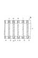
- FIG. 1is a plan view of the sample support of the first embodiment.
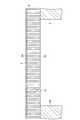
- FIG. 2is a sectional view of the sample support taken along the line II-II in FIG.
- FIG. 3is an enlarged cross-sectional view of a main part of the broken line part A in FIG.
- FIG. 4is an enlarged view of the substrate of the sample support shown in FIG.
- FIG. 5is a diagram illustrating steps of a mass spectrometry method according to an embodiment.
- FIG. 6is a diagram illustrating steps of a mass spectrometry method according to an embodiment.
- FIG. 7is a configuration diagram of a mass spectrometer according to an embodiment.
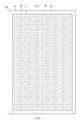
- FIG. 8is a diagram showing the results of mass spectrometry in Examples and Comparative Examples.
- FIG. 1is a plan view of the sample support of the first embodiment.
- FIG. 2is a sectional view of the sample support taken along the line II-II in FIG.
- FIG. 3is an enlarged cross-sectional view of a
- FIG. 9is an enlarged cross-sectional view of a main part of the sample support of the second embodiment.
- FIG. 10is a cross-sectional view of the sample support of the third embodiment.
- FIG. 11is a diagram showing a second step when the sample support shown in FIG. 10 is used.
- the sample support 1includes a substrate 2, a frame 3 (support substrate), and a conductive layer 4.
- the sample support 1is a sample support for ionization of a sample.
- the sample support 1is used for ionizing components of a sample to be measured, for example, when performing mass spectrometry.
- the substrate 2has a first surface 2a and a second surface 2b facing each other.
- a plurality of through holes 2care formed uniformly (with uniform distribution) in the substrate 2.
- Each through-hole 2cextends along the thickness direction of the substrate 2 (the direction perpendicular to the first surface 2a and the second surface 2b), and opens to the first surface 2a and the second surface 2b. .
- the substrate 2is formed in a rectangular plate shape by an insulating material, for example.
- the length of one side of the substrate 2 when viewed from the thickness direction of the substrate 2is, for example, about several centimeters, and the thickness of the substrate 2 is, for example, about 1 ⁇ m to 50 ⁇ m.
- the shape of the through hole 2c when viewed from the thickness direction of the substrate 2is, for example, a substantially circular shape.
- the width of the through hole 2cis, for example, about 1 nm to 700 nm.
- the width of the through hole 2cmeans the diameter of the through hole 2c when the shape of the through hole 2c is substantially circular when viewed from the thickness direction of the substrate 2, and the shape is other than substantially circular. In this case, it means the diameter (effective diameter) of a virtual maximum cylinder that fits in the through hole 2c.
- the frame 3is provided on the second surface 2b of the substrate 2 and supports the substrate 2 on the second surface 2b side.
- the frame 3is fixed to the second surface 2b of the substrate 2 with an adhesive material or the like.
- the adhesive materialfor example, an adhesive material with a low released gas (for example, low melting point glass, vacuum adhesive, etc.) can be used.
- the frame 3is formed in a rectangular plate shape that is larger than the substrate 2 when viewed from the thickness direction of the substrate 2.
- the frame 3is formed with a plurality of through portions 3 a that penetrate in the thickness direction of the frame 3 (that is, the thickness direction of the substrate 2). As shown in FIG. 1, the plurality of through portions 3a are arranged in a grid, for example.
- a portion of the substrate 2 corresponding to the penetrating portion 3afunctions as a measurement region R for measuring (ionizing) the sample.
- One penetrating portion 3acorresponds to one measurement region R.
- the solution containing the sample dropped from the second surface 2b side with respect to the substrate 2is passed through the plurality of through holes 2c provided in the measurement region R by the gravity and capillary phenomenon on the first surface 2a side. It functions as an area for moving to.
- the frame 3is formed in a rectangular plate shape by, for example, a magnetic metal material (for example, stainless steel material (SUS400 series)).
- the length of one side of the frame 3 when viewed from the thickness direction of the substrate 2is, for example, about several cm to 200 cm, and the thickness of the frame 3 is, for example, 3 mm or less.
- the shape of the through-hole 3a when viewed from the thickness direction of the substrate 2is, for example, a circle, and the diameter of the through-hole 3a in that case is, for example, about several mm to several tens of mm.
- the distance (pitch) between the centers of the adjacent through portions 3ais, for example, about several mm to several tens mm.
- the diameter of the penetration part 3ais 1.6 mm, and the pitch of adjacent penetration part 3a is 2.3 mm.
- Such a frame 3facilitates handling of the sample support 1 and suppresses deformation of the substrate 2 due to a temperature change or the like.
- the conductive layer 4is provided on the first surface 2 a of the substrate 2.
- the conductive layer 4includes a first surface 2 a of the substrate 2, a side surface of the substrate 2, and a part of the surface 3 b of the frame 3 on the substrate 2 side (thickness of the substrate 2). And a portion located outside the substrate 2 when viewed from the side).
- the conductive layer 4is not formed on the edge of the surface 3 b of the frame 3, but the conductive layer 4 may also be formed on the edge of the surface 3 b of the frame 3.
- the conductive layer 4covers a portion of the first surface 2 a of the substrate 2 where the through hole 2 c is not formed in the measurement region R. That is, the opening on the conductive layer 4 side of each through hole 2 c is not blocked by the conductive layer 4.
- the conductive layer 4is made of a conductive material. However, as the material of the conductive layer 4, it is preferable to use a metal having low affinity (reactivity) with the sample and high conductivity for the reasons described below.
- the conductive layer 4is formed of a metal such as Cu (copper) having a high affinity with a sample such as protein
- the sampleis attached with Cu atoms attached to the sample molecules during the ionization process of the sample described later.
- the detection resultis shifted in mass spectrometry to be described later by the amount of ionization and adhesion of Cu atoms. Therefore, it is preferable to use a metal having a low affinity with the sample as the material of the conductive layer 4.
- the higher the conductivity of the metalthe easier and stable application of a constant voltage is. Therefore, when the conductive layer 4 is formed of a metal having high conductivity, a voltage can be uniformly applied to the first surface 2a of the substrate 2 in the measurement region R. Also, the higher the conductivity, the higher the thermal conductivity. Therefore, when the conductive layer 4 is formed of a metal having high conductivity, it is possible to efficiently transmit energy of an energy beam (for example, laser light) irradiated to the substrate 2 to the sample through the conductive layer 4. It becomes. Therefore, it is preferable to use a highly conductive metal as the material of the conductive layer 4.
- an energy beamfor example, laser light
- the material of the conductive layer 4for example, Au (gold), Pt (platinum) or the like is preferably used.
- the conductive layer 4is formed to a thickness of about 1 nm to 350 nm by, for example, plating, atomic layer deposition (ALD), vapor deposition, sputtering, or the like.
- ALDatomic layer deposition
- vapor depositionvapor deposition
- sputteringor the like.
- Crchromium
- Ninickel
- Tititanium
- the conductive layer 4has a lower affinity for water than the second surface 2b of the substrate 2.
- the surface on the second surface 2b side(here, the second surface 2b) has a higher affinity for water than the surface on the first surface 2a side (here, the outer surface of the conductive layer 4) of the sample support 1. It is high. That is, the solution containing the sample is more likely to flow into the through hole 2c on the second surface 2b side than on the first surface 2a side. In addition, the solution containing the sample is less likely to flow out of the through hole 2c on the first surface 2a side than on the second surface 2b side.
- FIG. 4is an enlarged view of the substrate 2 when viewed from the thickness direction of the substrate 2.
- a black partis the through-hole 2c
- a white partis a partition part between the through-holes 2c.
- a plurality of through holes 2 c having a substantially constant widthare uniformly formed in the substrate 2.
- the aperture ratio of the through hole 2c in one measurement region Ris practically 10 to 80%. In particular, it is preferably 60 to 80%.
- the sizes of the plurality of through holes 2cmay be uneven with each other, or the plurality of through holes 2c may be partially connected to each other.
- the substrate 2 shown in FIG. 4is an alumina porous film formed by anodizing Al (aluminum).
- Alaluminum
- the surface portion of the Al substrateis oxidized, and a plurality of pores (portions to be through holes 2c) are formed in the surface portion of the Al substrate. Is done.
- the oxidized surface portionis peeled off from the Al substrate, and the peeled anodic oxide film is subjected to pore widening treatment for widening the pores, whereby the substrate 2 described above. Is obtained.
- the substrate 2is made of Ta (tantalum), Nb (niobium), Ti (titanium), Hf (hafnium), Zr (zirconium), Zn (zinc), W (tungsten), Bi (bismuth), Sb (antimony).
- Tatantalum
- Nbniobium
- Tititanium
- Hfhafnium
- Zrzirconium
- Znzinc
- Wtungsten
- Bibismuth
- Sbantimony
- itmay be formed by anodizing a valve metal other than Al, or by anodizing Si (silicon).
- a sample ionization method using the sample support 1will be described with reference to FIGS.
- a laser desorption ionization method using a laser beam as an energy beam irradiated for ionization of a sample(a part of a mass analysis method using a mass spectrometer 10 described later) will be described.
- the sample support 1 described aboveis prepared (first step).
- the sample support 1may be prepared by being manufactured by a person who performs the mass spectrometry method, or may be prepared by being acquired from a manufacturer or a seller of the sample support 1.
- sample solutiona solution containing the sample S (hereinafter referred to as “sample solution”) is dropped (second step).
- the sample solutionis dropped toward each penetration part 3a (that is, each measurement region R) of the frame 3 by, for example, a pipette P or the like.
- the dropping of the sample solutionmay be performed manually by an operator or mechanically by an apparatus.
- the sample solutionis dropped on each of the plurality of measurement regions R on the second surface 2b of the substrate 2.
- the component S1 of the sample Sis in the plurality of through holes 2c from the second surface 2b side. And the component S1 of the sample S that has moved into the plurality of through holes 2c is dried (third step). Specifically, as shown in FIG. 6A, after the second step, the state in which the second surface 2b is positioned on the upper side with respect to the first surface 2a is maintained, so that the sample solution Moves into the through-hole 2c due to gravity and capillary action, and the sample component S1 contained in the sample solution dries.
- the sample solutionis dropped on the second surface 2b, whereby the first surface 2a (conductive layer 4) is dropped.
- the sample solutioncan flow into the through-hole 2c more smoothly than when the sample solution is dropped.
- the component S1 of the sample Sis dried while suppressing the outflow of the sample solution from the first surface 2a side (movement along the surface of the conductive layer 4) by the conductive layer 4 provided on the first surface 2a. be able to.
- the sample support 1is inverted so that the first surface 2a is located on the upper side with respect to the second surface 2b,
- the first surface 2ais placed on the placement surface 5a of the holding substrate 5 (see FIG. 7) with the first surface 2a positioned on the upper side with respect to the second surface 2b. That is, the sample support 1 is placed on the placement surface 5a so that the second surface 2b faces the placement surface 5a.
- the holding substrate 5(mounting unit) is, for example, a magnetic metal material (for example, a substrate made of stainless steel 400 or the like).
- the holding substrate 5is preferably a magnet holder for fixing the frame 3.
- the material of the magnet holderis, for example, ferrite or alnico.
- the sample support 1 and the holding substrate 5are placed on a support 12 (see FIG. 7) of a mass spectrometer 10 (see FIG. 7) described later.
- the component S1 of the sample Sis ionized by irradiating the first surface 2a with the laser light L while applying a voltage to the conductive layer 4. (4th process). Specifically, the component S1 remaining in the through hole 2c of the substrate 2 (particularly on the first surface 2a side) is ionized, and the sample ion S2 (ionized component S1) is released. More specifically, the energy is transmitted from the conductive layer 4 (see FIG. 2) that has absorbed the energy of the laser light L to the component S1 of the sample S remaining in the through hole 2c, and the energy of the sample S that has acquired the energy. The component S1 is vaporized and a charge is acquired to become the sample ion S2.
- the first to fourth steps described abovecorrespond to the ionization method (here, laser desorption ionization method) of the sample S using the sample support 1.
- the released sample ions S2are generated by the mass separation unit 152 (see FIG. 7) due to the pressure difference between the support unit 12 (see FIG. 7) side and the ion detection unit 15 (see FIG. 7) and the electric field of the ion guide 151 (see FIG. 7). (See FIG. 7).
- the mass separator 152the sample ions S2 are separated according to the mass.
- the sample ions S2 separated according to the massare detected by the ion detector 153 (see FIG. 7) (fifth step).
- the mass spectrometer 10is a mass spectrometer that uses time-of-flight mass spectrometry (TOF-MS).
- TOF-MStime-of-flight mass spectrometry
- the fourth step and the fifth stepare performed for each measurement region R. That is, in the fourth step, the laser light L is irradiated for each measurement region R, and the component S1 is ionized for each measurement region R. Further, the ionized component S1 (sample ion S2) is detected for each measurement region R by the ion detector 153. Thereby, a mass spectrometry result (mass spectrum etc.) is obtained for every measurement field R.
- the mass spectrometer 10includes a chamber 11, a support unit 12, a laser beam irradiation unit 13, a voltage application unit 14, an ion detection unit 15, a support mechanism 16, and a sample dropping unit. 17, a control unit 18, an operation unit 19, and a display unit 20.
- the chamber 11forms a space to be evacuated.
- the support unit 12supports the holding substrate 5 and the sample support 1 in the space in the chamber 11 in a state where the sample support 1 is placed on the holding substrate 5.
- the support unit 12is, for example, a stage that can operate along a plane perpendicular to the thickness direction of the substrate 2.
- the laser beam irradiation unit 13irradiates the first surface 2 a of the sample support 1 supported by the support unit 12 with the laser beam L through the window 11 a provided in the chamber 11.
- the laser light Lis, for example, light having a wavelength in the ultraviolet region.
- the voltage application unit 14is connected to the conductive layer 4 (see FIG. 2) of the sample support 1 supported by the support unit 12 via, for example, the mounting surface 5a of the holding substrate 5 and a conductive member (not shown).
- the conductive memberis, for example, a tape that has conductivity and connects the mounting surface 5a and the conductive layer 4 (for example, a portion on the surface 3b of the frame 3).
- the conductive layer 4extends not only on the first surface 2a of the substrate 2 but also on the surface 3b of the frame 3, so that the conductive layer 4 and the tape can be electrically connected on the surface 3b of the frame 3. it can. For this reason, it is possible to apply a voltage to the conductive layer 4 without reducing the effective area of the substrate 2 (area where the through-hole 2c is provided and can be used for measurement).
- the ion detector 15irradiates the first surface 2a with the laser light L while applying a voltage to the sample ion S2 (that is, the conductive layer 4 in the space in the chamber 11).
- the component S1) of the ionized sample Sis detected.
- the laser beam Lis applied to the first surface 2a while a voltage is applied to the conductive layer 4, the component S1 of the sample S is moved toward the first surface 2a via a plurality of through holes 2c due to capillary action. Moved and dry.
- the support unit 12is operated by the control unit 18, so that the laser beam irradiation unit 13 scans and irradiates the measurement region R with the laser beam L, and the ion detection unit 15 For the measurement region R, the sample ion S2 is detected.
- the scanning of the laser light L with respect to each measurement region Rcan be performed by operating at least one of the support unit 12 and the laser light irradiation unit 13 by the control unit 18.
- the ion detector 15has an ion guide 151, a mass separator 152, and an ion detector 153.
- the sample ions S2 released into the space in the chamber 11are drawn into the mass separation unit 152 due to the pressure difference between the support unit 12 side and the ion detection unit 15 side and the electric field of the ion guide 151.
- the mass separator 152the sample ions S2 are separated according to the mass.
- the sample ions S2 separated according to the massare detected by the ion detector 153.
- the support mechanism 16supports the sample support 1 and reverses the sample support 1.
- the support mechanism 16includes a grip portion 16A that grips a side portion of the sample support 1 (for example, an edge portion of the frame 3), and an arm portion 16B that is connected to the grip portion 16A.
- the arm portion 16Bis configured to be extendable and contractible.
- the sample support 1 held by the holding portion 16Amoves from the sample dropping position (the position indicated by the broken line in FIG. 7) to the position on the support portion 12 (the position indicated by the broken line).
- the positioncan be moved to a position indicated by a solid line in FIG.
- the arm portion 16Bis configured to be rotatable around the axial direction.
- the sample support 1can be reversed by the rotation of the arm portion 16B.
- the sample dropping unit 17holds the pipette P in which the sample solution is stored, and is operated by the control unit 18 to drop the sample solution in the pipette P to a specified position.
- the support mechanism 16supports the sample support 1 so that the second surface 2b is positioned above the first surface 2a at the sample dropping position.
- the sample dropping unit 17drops the sample solution to each penetrating part 3 a (that is, each measurement region R) of the frame 3.
- the sample dropping unit 17is operated by the control unit 18 so that the sample solution is dropped from the tip of the pipette P to each measurement region R while sequentially moving the pipette P to a position above each measurement region R. To do. Thereby, the sample solution is dropped onto each of the plurality of measurement regions R.
- the support mechanism 16inverts the sample support 1 so that the first surface 2a is positioned on the upper side with respect to the second surface 2b. Thereafter, the support mechanism 16 moves the sample support 1 from the sample dropping position to a position on the support 12 and releases the grip of the sample support 1 by the grip 16A, whereby the sample support 1 is supported by the support 16. 12 (here, on the holding substrate 5).
- the control unit 18controls the operation of each unit of the mass spectrometer 10 and performs mass analysis (spectrum analysis or the like) of molecules constituting the sample S based on the detection result of the sample ion S2 by the ion detection unit 15. .
- the control unit 18is configured as a computer device including a processor, a memory, a storage, a communication device, and the like.
- the operation unit 19is an interface for an operator to input instructions and the like.
- the display unit 20is a display that displays the results of mass spectrometry of the molecules constituting the sample S.
- the sample Sis placed on the second surface 2b in a state where the sample support 1 is supported such that the second surface 2b is positioned on the upper side with respect to the first surface 2a.
- a solutionsample solution
- the conductive layer 4 having a lower affinity for water than the second surface 2bis provided on the first surface 2a, by dropping the sample solution onto the second surface 2b, the first surface 2a ( The sample solution can flow into the through hole 2c more smoothly than when the sample solution is dropped onto the conductive layer 4).
- the component S1 of the sample Scan be dried while suppressing the outflow of the sample solution from the first surface 2a side by the conductive layer 4 provided on the first surface 2a.
- the signal intensity detected by the ion detector 15can be improved.
- FIG. 8Ashows a mass spectrum obtained by the mass spectrometry method of the comparative example (hereinafter simply referred to as “comparative example”)
- FIG. 8Bshows the mass spectrometry method of the above embodiment (hereinafter, “comparative example”).
- the mass spectrum obtained by "Example”)is shown.
- a sample solution containing acetylcholinesterase (AChE) as sample Swas used.
- the comparative exampleis different from the example in that the following steps are performed instead of the second step and the third step.
- the sample solutionis applied to the first surface 2a (the conductive layer 4) in a state where the sample support 1 is supported so that the first surface 2a is located on the upper side with respect to the second surface 2b. It was dripped.
- an organic solventfor example, acetonitrile or the like
- the component S1 of the sample Sis in the plurality of through holes 2c from the first surface 2a side.
- the component S1 of the sample S moved into the plurality of through holes 2cwas dried. That is, in the comparative example, the sample was dropped and dried from the first surface 2a side, which is the side irradiated with the laser light L, while the state where the first surface 2a side was the upper surface was maintained. Subsequent irradiation of the laser beam L (the fourth step) was performed in the same manner as in the example.
- the signal intensitywas relatively small and the noise was relatively large.
- the resultwas that the signal intensity was relatively large and the noise was relatively small.
- the sample solutioncan be appropriately introduced into the through-hole 2c without adding an organic solvent for lowering the surface tension of the sample solution as in the comparative example, and compared with the comparative example in which the organic solvent is added. It was also confirmed that the signal strength could be improved.
- the sample solutioncan be guided into the through-hole 2c relatively smoothly from the side having a relatively high affinity for water (the second surface 2b side) and has an affinity for water. Since the outflow of the sample solution from the relatively low side (first surface 2a side) can be suppressed, the through hole 2c can function as if it were a test tube.
- a plurality of different solutionsfor example, a sample solution containing the sample S to be measured and a matrix solution containing a matrix or the like
- the mass spectrometry method of the present embodimentis effective in the case where measurement is performed after reacting a plurality of different solutions in the through-hole 2c (for example, measurement is performed by adding a matrix to the sample solution).
- the sample solution that has flowed into the through portion 3ais difficult to ooze out from the first surface 2a side. For this reason, on the first surface 2a side, the sample solution flowing out from the through hole 2c provided corresponding to one through portion 3a penetrates into the through hole 2c provided corresponding to the other through portion 3a. The occurrence of so-called crosstalk is suppressed.
- the ionization methodsupports the sample on the mounting surface 5a so that the second surface 2b faces the mounting surface 5a between the completion of the third step and the start of the fourth step.
- a step of placing the body 1is performed.
- the sample support 1is placed on the placement surface 5a after being inverted so that the second surface 2b is positioned on the lower side. Accordingly, the first support 2a side can be exposed upward while the sample support 1 is stably supported by the holding substrate 5, and therefore the laser beam L can be appropriately irradiated in the fourth step. it can.
- the sample support 1 used in the ionization methodis provided with a plurality of measurement regions R that are separated from each other when viewed from the thickness direction of the substrate 2.
- a plurality of through holes 2care formed.
- the sample solutionis dropped on each of the plurality of measurement regions R on the second surface 2b.
- the laser light Lis irradiated for each measurement region R, and the component S1 of the sample S is ionized for each measurement region R.
- the sample support 1 used for the ionization methodincludes a frame 3 that supports the substrate 2 on the second surface 2b side.
- the frame 3includes a frame 3 corresponding to each of the plurality of measurement regions R.
- a plurality of penetrating portions 3a penetrating in the thickness directionare formed. According to such a frame 3, the handling property of the sample support 1 can be improved. Specifically, since the deformation of the substrate 2 is suppressed by the frame 3 provided integrally with the substrate 2, for example, when the sample support 1 is supported or inverted by the support mechanism 16 as described above, the substrate 2. Can be prevented from being bent. In addition, since the plurality of measurement regions R are partitioned by the frame 3 (see FIG. 1), the sample solution can be easily dropped onto each measurement region R in the second step.
- the operatorwhen the operator manually drops the sample solution, the operator can easily grasp each measurement region R using the penetrating portion 3a of the frame 3 as a mark.
- the sample solutionis mechanically dropped by the sample dropping unit 17 as in the above embodiment, for example, the following effects are exhibited. That is, the second surface 2b side of the sample support 1 is imaged by an imaging unit (such as a camera) (not shown), and the control unit 18 analyzes the image captured by the imaging unit and recognizes a position corresponding to the penetrating part 3a. This makes it possible to adjust the sample dropping position with high accuracy.
- an imaging unitsuch as a camera
- the conductive layer 4 having a lower affinity for water than the second surface 2bis provided on the first surface 2a. For this reason, for example, by dropping the sample solution onto the second surface 2b, the sample solution flows into the through hole 2c more smoothly than when dropping the sample solution onto the first surface 2a (conductive layer 4). Can be made. Moreover, the component S1 of the sample S can be dried while suppressing the outflow of the sample solution from the first surface 2a side by the conductive layer 4 provided on the first surface 2a. Thereby, since the component S1 of the sample S can be appropriately introduced into the through-hole 2c, the signal intensity when detecting the component S1 ionized by irradiation with the laser light L can be improved.
- the handleability of the sample support 1is improved by the frame 3 provided on the second surface 2 b side. Further, since the plurality of measurement regions R are partitioned by the frame 3, the sample solution can be easily dropped onto each measurement region R. Therefore, according to the sample support 1, ionization of a large number of samples (that is, sample solutions dropped on each measurement region R) can be performed efficiently and easily.
- a sample support 1 ⁇ / b> Amay be prepared instead of the sample support 1.
- the sample support 1Ais different from the sample support 1 in that a hydrophilic coating layer 6 is provided on the inner surface of the portion including the edge of the second surface 2b of the substrate 2 and the second surface 2b side of the through hole 2c. It is different. Further, the sample support 1A is provided with a hydrophobic coating layer 7 having a lower affinity for water than the conductive layer 4 on the surface 4a of the conductive layer 4 opposite to the substrate 2. 1 and different.
- Other configurations of the sample support 1 ⁇ / b> Aare the same as those of the sample support 1.
- the hydrophilic coating layer 6is provided at least in a region corresponding to the measurement region R.
- the coating layer 6is a layer formed by film formation of, for example, titanium oxide (TiO 2) or zinc oxide (ZnO).
- the coating layer 6is formed by, for example, an atomic layer deposition method.
- the thickness of the coating layer 6is, for example, 1 nm to 50 nm.
- the width of the portion of the coating layer 6 along the inner surface of the portion including the edge portion on the second surface 2b side of each through hole 2c (that is, the portion entering the through hole 2c)(the thickness direction of the substrate 2)
- the length in (1)is, for example, 1 nm to 1000 nm.
- the hydrophobic coating layer 7is provided at least in a region corresponding to the measurement region R.
- the coating layer 7is a layer (metal film) formed by metal deposition, for example.
- the coating layer 7is made of a material having a lower affinity for water than the conductive layer 4.
- the coating layer 7may be a layer formed of a self-assembled monomolecular film (SAM film: Self-Assembled Monolayer).
- SAM filmSelf-Assembled Monolayer
- the coating layer 7should just be provided in the surface on the opposite side to the board
- the thickness of the coating layer 7is, for example, 1 nm to 100 nm.
- the hydrophilic coating layer 6can effectively promote the inflow of the sample solution dropped onto the second surface 2b into the through hole 2c. That is, in the second step, the sample solution dropped on the second surface 2b (on the coating layer 6) easily flows into the through holes 2c through the coating layer 6. That is, the coating layer 6 plays a role of appropriately guiding the sample solution on the second surface 2b side into each through hole 2c. Thereby, component S1 of sample S can be appropriately made to flow in each through-hole 2c. As a result, it is possible to further improve the signal intensity when detecting the ionized component S1.
- the hydrophobic coating layer 7can effectively suppress the outflow of the sample solution from the first surface 2a side. That is, in the second step and the third step, the sample solution about to flow out from the opening on the first surface 2a side of each through-hole 2c is along the first surface 2a (through the coating layer 7) to the outside. It has become difficult to leak. That is, the coating layer 7 plays a role of preventing the sample solution in each through-hole 2c from flowing out along the first surface 2a. Thereby, the outflow from the 1st surface 2a side of the component S1 of the sample S which flowed in into each through-hole 2c can be suppressed, and the said component S1 can be appropriately stopped in each through-hole 2c. As a result, the component S1 of the sample S is concentrated in each through hole 2c, and the signal intensity when detecting the ionized component S1 can be further improved.
- the sample support 1A including both the coating layer 6 and the coating layer 7 and the ionization method using the sample support 1Ahave been described.
- the ionization methodin the first step, A sample support including only one of the coating layer 6 and the coating layer 7 may be prepared. In that case, the effect mentioned above according to the coating layer 6 or the coating layer 7 with which a sample support body is provided can be acquired.
- a sample support 1 ⁇ / b> Bmay be prepared instead of the sample support 1.
- the sample support 1Bis different from the sample support 1 in that a frame 3B is provided instead of the frame 3.
- the other configuration of the sample support 1Bis the same as that of the sample support 1.
- the frame 3Bis different from the frame 3 in that a through portion 3c is provided instead of the through portion 3a.
- Other configurations of the frame 3Bare the same as those of the frame 3.
- the penetrating portion 3 chas a tapered shape that becomes wider as the distance from the second surface 2 b of the substrate 2 increases.
- the tip of the pipette Pcan easily enter the penetration part 3c, so that the sample solution can be easily dropped onto the measurement region R.
- the position of the tip of the pipette Pis the target position ( For example, even if the sample solution slightly deviates from the center position of the measurement region R when viewed from the thickness direction of the substrate 2, the sample solution hits the side surface of the penetrating portion 3c and is introduced into the measurement region R by gravity.
- the substrate 2 described abovemay have conductivity, and a voltage may be applied to the substrate 2 in the ionization method.
- the conductive layer 4can be omitted from the sample support, and the same effect as in the case where the sample support including the conductive layer 4 described above is used can be obtained.
- the substrate 2only needs to be surface-treated so that the surface on the first surface 2a side has a lower affinity for water than the surface on the second surface 2b side.
- the hydrophilic coating layer 6 described abovemay be provided on the inner surface of a portion including the second surface 2b of the conductive substrate 2 and the edge of the through hole 2c on the second surface 2b side.
- the inflow of the sample solution dropped onto the second surface 2b into the through hole 2ccan be promoted.
- the above-described hydrophobic coating layer 7may be provided on the first surface 2a of the substrate 2 having conductivity.
- the outflow of the sample solution that has moved through the through hole 2c to the first surface 2a sidecan be suppressed.
- the sample support 1is changed from the state in which the second surface 2b is located on the upper side to the state in which the first surface 2a is located on the upper side.
- the process of inverting the sample support 1may be omitted.
- the sample support 1is supported by the support mechanism 16 with the second surface 2b positioned on the upper side and the laser beam L is irradiated from below, the sample support 1 is reversed.
- the process which mounts the sample support body 1 on the mounting surface of a mounting partmay be abbreviate
- the sample support 1when performing the mass spectrometry method using the mass spectrometer 10, the sample support 1 may be directly placed and fixed on the support portion 12. That is, the holding substrate 5 may be omitted.
- the support portion 12functions as a placement portion, and the upper surface of the support portion 12 functions as a placement surface.
- the plurality of measurement regions Rare defined by the plurality of penetration portions 3a of the frame 3 (or the plurality of penetration portions 3c of the frame 3B).
- the number of portions 3a or penetrating portions 3c)may be one.
- the ionization method of the sample described abovecan be used not only for mass analysis of molecules constituting the sample S but also for other measurements and experiments such as ion mobility measurement.
- the laser beam Lis used as the energy beam for ionizing the sample.
- the energy beamis not limited to the laser beam L, and may be, for example, an ion beam, an electron beam, or the like. .
Landscapes
- Physics & Mathematics (AREA)
- Chemical & Material Sciences (AREA)
- Analytical Chemistry (AREA)
- Health & Medical Sciences (AREA)
- Life Sciences & Earth Sciences (AREA)
- Spectroscopy & Molecular Physics (AREA)
- Immunology (AREA)
- Biochemistry (AREA)
- General Health & Medical Sciences (AREA)
- General Physics & Mathematics (AREA)
- Pathology (AREA)
- Electrochemistry (AREA)
- Molecular Biology (AREA)
- Chemical Kinetics & Catalysis (AREA)
- Optics & Photonics (AREA)
- Other Investigation Or Analysis Of Materials By Electrical Means (AREA)
- Electron Tubes For Measurement (AREA)
- Engineering & Computer Science (AREA)
- Plasma & Fusion (AREA)
Abstract
Description
Translated fromJapanese本開示は、イオン化方法及び試料支持体に関する。The present disclosure relates to an ionization method and a sample support.
従来、生体試料等の試料の質量分析において、試料をイオン化するための試料支持体が知られている(例えば、特許文献1参照)。このような試料支持体は、互いに対向する第1表面及び第2表面に開口する複数の貫通孔が形成された基板を備えている。Conventionally, a sample support for ionizing a sample in mass spectrometry of a sample such as a biological sample is known (for example, see Patent Document 1). Such a sample support is provided with a substrate on which a plurality of through-holes opened in the first surface and the second surface facing each other are formed.
上述したような質量分析においては、イオン化された試料(試料イオン)が検出され、その検出結果に基づいて試料の質量分析が実施される。このような質量分析においては、信号強度(感度)の向上が望まれている。In the mass spectrometry as described above, an ionized sample (sample ion) is detected, and mass analysis of the sample is performed based on the detection result. In such mass spectrometry, improvement of signal intensity (sensitivity) is desired.
そこで、本開示は、試料イオンを検出する際における信号強度を向上させることができるイオン化方法及び試料支持体を提供することを目的とする。Therefore, an object of the present disclosure is to provide an ionization method and a sample support capable of improving the signal intensity when detecting sample ions.
本開示の第1の側面に係るイオン化方法は、互いに対向する第1表面及び第2表面に開口する複数の貫通孔が形成された基板と、少なくとも第1表面に設けられ、第2表面よりも水に対する親和性が低い導電層と、を備える試料支持体を用意する第1工程と、第1表面に対して第2表面が上側に位置するように試料支持体が支持された状態で、第2表面に対して試料を含む溶液を滴下する第2工程と、第1表面に対して第2表面が上側に位置するように試料支持体が支持された状態で、試料の成分を第2表面側から複数の貫通孔内に移動させると共に、複数の貫通孔内に移動した試料の成分を乾燥させる第3工程と、導電層に電圧を印加しつつ第1表面に対してエネルギー線を照射することにより、試料の成分をイオン化する第4工程と、を含む。The ionization method according to the first aspect of the present disclosure includes a substrate on which a plurality of through-holes opening in a first surface and a second surface facing each other, and at least the first surface, which is provided on the first surface. A first step of preparing a sample support comprising a conductive layer having a low affinity for water; and a state in which the sample support is supported such that the second surface is located on the upper side with respect to the first surface. A second step of dropping a solution containing the sample on the two surfaces; and the sample component in the state where the sample support is supported so that the second surface is located on the upper side of the first surface. A third step of moving the sample from the side into the plurality of through holes and drying the components of the sample moved into the plurality of through holes, and irradiating the first surface with energy rays while applying a voltage to the conductive layer A fourth step of ionizing the components of the sample, Including.
第1の側面に係るイオン化方法では、第1表面に対して第2表面が上側に位置するように試料支持体が支持された状態で、第2表面に対して試料を含む溶液(以下「試料溶液」)が滴下される。ここで、第2表面よりも水に対する親和性が低い導電層が第1表面に設けられているため、第2表面に対して試料溶液を滴下することにより、第1表面(導電層)に対して試料溶液を滴下する場合よりもスムーズに試料溶液を貫通孔内に流入させることができる。また、第1表面に設けられた導電層によって、第1表面側からの試料溶液の流出を抑制しつつ、当該試料の成分を乾燥させることができる。これにより、貫通孔内に試料の成分を適切に導入することができるため、エネルギー線の照射によってイオン化された成分を検出する際における信号強度を向上させることができる。In the ionization method according to the first aspect, a solution containing a sample with respect to the second surface (hereinafter referred to as “sample”) in a state where the sample support is supported so that the second surface is positioned on the upper side with respect to the first surface. Solution ") is added dropwise. Here, since the conductive layer having a lower affinity for water than the second surface is provided on the first surface, the sample solution is dropped on the second surface, whereby the first surface (conductive layer) is dropped. Thus, the sample solution can flow into the through-hole more smoothly than when the sample solution is dropped. Moreover, the component of the sample can be dried while suppressing the outflow of the sample solution from the first surface side by the conductive layer provided on the first surface. Thereby, since the component of a sample can be introduced appropriately into the through hole, the signal intensity at the time of detecting a component ionized by irradiation with energy rays can be improved.
第1の側面に係るイオン化方法では、第1工程において、第2表面及び貫通孔の第2表面側の縁部を含む部分の内面に親水性のコーティング層が設けられた試料支持体を用意してもよい。この場合、親水性のコーティング層によって、第2表面に対して滴下された試料溶液の貫通孔内への流入を効果的に促進することができる。In the ionization method according to the first aspect, in the first step, a sample support is prepared in which a hydrophilic coating layer is provided on the inner surface of a portion including the second surface and the edge on the second surface side of the through hole. May be. In this case, the hydrophilic coating layer can effectively promote the inflow of the sample solution dropped onto the second surface into the through hole.
第1の側面に係るイオン化方法では、第1工程において、導電層の基板とは反対側の表面に、導電層よりも水に対する親和性が低い疎水性のコーティング層が設けられた試料支持体を用意してもよい。この場合、疎水性のコーティング層によって、第1表面側からの試料溶液の流出を効果的に抑制することができる。In the ionization method according to the first aspect, in the first step, the sample support is provided with a hydrophobic coating layer having a lower affinity for water than the conductive layer on the surface of the conductive layer opposite to the substrate. You may prepare. In this case, the outflow of the sample solution from the first surface side can be effectively suppressed by the hydrophobic coating layer.
本開示の第2の側面に係るイオン化方法は、導電性を有し、互いに対向する第1表面及び第2表面に開口する複数の貫通孔が形成された基板を備え、第1表面側の面の方が第2表面側の面よりも水に対する親和性が低い試料支持体を用意する第1工程と、第1表面に対して第2表面が上側に位置するように試料支持体が支持された状態で、第2表面に対して試料を含む溶液を滴下する第2工程と、第1表面に対して第2表面が上側に位置するように試料支持体が支持された状態で、試料の成分を第2表面側から複数の貫通孔内に移動させると共に、複数の貫通孔内に移動した試料の成分を乾燥させる第3工程と、基板に電圧を印加しつつ第1表面に対してエネルギー線を照射することにより、試料の成分をイオン化する第4工程と、を含む。An ionization method according to a second aspect of the present disclosure includes a substrate having conductivity, a first surface facing each other, and a substrate having a plurality of through holes opened in the second surface, the first surface side surface The first step is to prepare a sample support having a lower affinity for water than the surface on the second surface side, and the sample support is supported so that the second surface is located on the upper side with respect to the first surface. In a state where the sample support is supported so that the second surface is located on the upper side with respect to the first surface, the second step of dropping the solution containing the sample onto the second surface A third step of moving the component from the second surface side into the plurality of through-holes and drying the component of the sample moved into the plurality of through-holes; and applying energy to the first surface while applying a voltage to the substrate And a fourth step of ionizing the components of the sample by irradiating the line
第2の側面に係るイオン化方法によれば、試料支持体において導電層を省略することができると共に、上述した導電層を有する試料支持体を用いる場合と同様の効果を得ることができる。According to the ionization method according to the second aspect, the conductive layer can be omitted from the sample support, and the same effect as when using the sample support having the conductive layer described above can be obtained.
第2の側面に係るイオン化方法では、第1工程において、第2表面及び貫通孔の第2表面側の縁部を含む部分の内面に親水性のコーティング層が設けられた試料支持体を用意してもよい。この場合、親水性のコーティング層によって、第2表面に対して滴下された試料溶液の貫通孔内への流入を効果的に促進することができる。In the ionization method according to the second aspect, in the first step, a sample support is prepared in which a hydrophilic coating layer is provided on the inner surface of the portion including the second surface and the edge on the second surface side of the through hole. May be. In this case, the hydrophilic coating layer can effectively promote the inflow of the sample solution dropped onto the second surface into the through hole.
第2の側面に係るイオン化方法では、第1工程において、第1表面に疎水性のコーティング層が設けられた試料支持体を用意してもよい。この場合、疎水性のコーティング層によって、第1表面側からの試料溶液の流出を効果的に抑制することができる。In the ionization method according to the second aspect, a sample support provided with a hydrophobic coating layer on the first surface may be prepared in the first step. In this case, the outflow of the sample solution from the first surface side can be effectively suppressed by the hydrophobic coating layer.
上記第1及び第2のイオン化方法では、試料支持体には、基板の厚さ方向から見て互いに分離された複数の測定領域が設けられており、複数の測定領域の各々において、複数の貫通孔が形成されており、第2工程において、第2表面における複数の測定領域の各々に対して試料を含む溶液を滴下し、第4工程において、測定領域毎にエネルギー線を照射し、測定領域毎に試料の成分をイオン化してもよい。この場合、複数の測定領域を用いて多数のサンプル(すなわち、各測定領域に滴下される試料溶液)のイオン化及び測定を効率的に実施することが可能となる。In the first and second ionization methods, the sample support is provided with a plurality of measurement regions separated from each other when viewed from the thickness direction of the substrate, and a plurality of penetrations are provided in each of the plurality of measurement regions. A hole is formed, and in the second step, a solution containing a sample is dropped on each of the plurality of measurement regions on the second surface, and in the fourth step, an energy beam is irradiated for each measurement region. Sample components may be ionized each time. In this case, it becomes possible to efficiently perform ionization and measurement of a large number of samples (that is, sample solutions dropped on each measurement region) using a plurality of measurement regions.
また、試料支持体は、第2表面側において基板を支持する支持基板を備え、支持基板には、複数の測定領域の各々に対応して支持基板の厚さ方向に貫通する複数の貫通部が形成されていてもよい。この場合、支持基板によって試料支持体のハンドリング性を向上させることができる。また、支持基板によって複数の測定領域が仕切られることにより、第2工程において、各測定領域に対して試料溶液を容易に滴下することが可能となる。The sample support includes a support substrate that supports the substrate on the second surface side, and the support substrate has a plurality of through portions that penetrate in the thickness direction of the support substrate corresponding to each of the plurality of measurement regions. It may be formed. In this case, the handling property of the sample support can be improved by the support substrate. Further, since the plurality of measurement regions are partitioned by the support substrate, the sample solution can be easily dropped onto each measurement region in the second step.
また、貫通部は、第2表面から遠ざかるほど幅が広くなるテーパ形状をなしていてもよい。この場合、貫通部を上記テーパ形状としない場合(例えば柱状とする場合)と比較して、試料溶液が滴下される側の貫通部の開口を拡げることができる。これにより、第2工程における試料溶液の滴下の際に要求される精度(滴下位置に関する精度)を緩和することができる。Further, the penetrating portion may have a tapered shape in which the width increases as the distance from the second surface increases. In this case, compared with the case where the penetrating portion is not tapered (for example, a columnar shape), the opening of the penetrating portion where the sample solution is dropped can be expanded. Thereby, the precision (accuracy regarding a dropping position) requested | required in the case of dripping of the sample solution in a 2nd process can be eased.
また、上記イオン化方法は、第3工程を完了してから第4工程を開始するまでの間に、載置部の載置面に第2表面が対向するように、載置面に試料支持体を載置する工程を更に含んでもよい。この場合、第3工程の後に、試料支持体は、第2表面が下側に位置するように反転させられた上で載置面に載置される。これにより、試料支持体を載置部によって安定的に支持しつつ第1表面側を上方に露出させることができるため、第4工程におけるエネルギー線の照射を適切に実施することができる。Further, in the ionization method, the sample support is placed on the placement surface so that the second surface faces the placement surface of the placement portion between the completion of the third step and the start of the fourth step. May be further included. In this case, after the third step, the sample support is placed on the placement surface after being inverted so that the second surface is positioned on the lower side. Thereby, since the 1st surface side can be exposed upwards, supporting a sample support body stably by a mounting part, irradiation of energy rays in the 4th process can be performed appropriately.
本開示の第1の側面に係る試料支持体は、互いに対向する第1表面及び第2表面に開口する複数の貫通孔が形成された基板と、少なくとも第1表面に設けられ、第2表面よりも水に対する親和性が低い導電層と、第2表面側において基板を支持する支持基板と、を備え、支持基板には、基板の厚さ方向から見て互いに分離された複数の測定領域の各々に対応して支持基板の厚さ方向に貫通する複数の貫通部が形成されており、複数の測定領域の各々は、基板の厚さ方向から見て複数の貫通孔を含む領域である。The sample support according to the first aspect of the present disclosure is provided on a substrate having a plurality of through-holes opened on a first surface and a second surface facing each other, at least on the first surface, and from a second surface. Each of the plurality of measurement regions separated from each other as viewed from the thickness direction of the substrate. The conductive layer has a low affinity for water and a support substrate that supports the substrate on the second surface side. A plurality of penetrating portions penetrating in the thickness direction of the support substrate are formed correspondingly to each other, and each of the plurality of measurement regions is a region including a plurality of through holes when viewed from the thickness direction of the substrate.
第1の側面に係る試料支持体では、第2表面よりも水に対する親和性が低い導電層が第1表面に設けられている。このため、例えば第2表面に対して試料溶液を滴下することにより、第1表面(導電層)に対して試料溶液を滴下する場合よりもスムーズに試料溶液を貫通孔内に流入させることができる。また、第1表面に設けられた導電層によって、第1表面側からの試料溶液の流出を抑制しつつ、当該試料の成分を乾燥させることができる。これにより、貫通孔内に試料の成分を適切に導入することができるため、エネルギー線の照射によってイオン化された成分を検出する際における信号強度を向上させることができる。また、上記試料支持体では、第2表面側に設けられた支持基板によって、試料支持体のハンドリング性が向上させられている。さらに、支持基板によって複数の測定領域が仕切られていることにより、各測定領域に対して試料溶液を容易に滴下することが可能となっている。したがって、上記試料支持体によれば、多数のサンプル(すなわち、各測定領域に滴下される試料溶液)のイオン化を効率的且つ容易に行うことができる。In the sample support according to the first aspect, a conductive layer having a lower affinity for water than the second surface is provided on the first surface. For this reason, for example, by dropping the sample solution onto the second surface, the sample solution can flow into the through-hole more smoothly than when the sample solution is dropped onto the first surface (conductive layer). . Moreover, the component of the sample can be dried while suppressing the outflow of the sample solution from the first surface side by the conductive layer provided on the first surface. Thereby, since the component of a sample can be introduced appropriately into the through hole, the signal intensity at the time of detecting a component ionized by irradiation with energy rays can be improved. In the sample support, the handling property of the sample support is improved by the support substrate provided on the second surface side. Further, since the plurality of measurement regions are partitioned by the support substrate, the sample solution can be easily dropped onto each measurement region. Therefore, according to the sample support, ionization of a large number of samples (that is, sample solutions dropped on each measurement region) can be performed efficiently and easily.
本開示の第2の側面に係る試料支持体は、導電性を有し、互いに対向する第1表面及び第2表面に開口する複数の貫通孔が形成された基板と、第2表面側において基板を支持する支持基板と、を備え、第1表面側の面の方が第2表面側の面よりも水に対する親和性が低く、支持基板には、基板の厚さ方向から見て互いに分離された複数の測定領域の各々に対応する複数の貫通部が形成されており、複数の測定領域の各々は、基板の厚さ方向から見て複数の貫通孔を含む領域である。The sample support according to the second aspect of the present disclosure includes a substrate having a plurality of through-holes that are electrically conductive and open to the first surface and the second surface facing each other, and a substrate on the second surface side. A support substrate that supports the substrate, and the first surface side surface has a lower affinity for water than the second surface side surface, and the support substrate is separated from each other when viewed from the thickness direction of the substrate. A plurality of through portions corresponding to each of the plurality of measurement regions are formed, and each of the plurality of measurement regions is a region including a plurality of through holes when viewed from the thickness direction of the substrate.
第2の側面に係る試料支持体によれば、試料支持体において導電層を省略することができると共に、上述した導電層を有する試料支持体と同様の効果を得ることができる。According to the sample support according to the second aspect, the conductive layer can be omitted from the sample support and the same effect as that of the sample support having the conductive layer described above can be obtained.
上記第1及び第2の側面に係る試料支持体において、貫通部は、第2表面から遠ざかるほど幅が広くなるテーパ形状をなしていてもよい。この場合、貫通部を上記テーパ形状としない場合(例えば柱状とする場合)と比較して、第2表面側に対する溶液の滴下を容易に行うことができる。すなわち、溶液が滴下される側の貫通部の開口を拡げることができるため、溶液の滴下の際に要求される精度(溶液の滴下位置に関する精度)を緩和することができる。In the sample support according to the first and second side surfaces, the penetrating portion may have a taper shape whose width increases as the distance from the second surface increases. In this case, the solution can be easily dropped onto the second surface side as compared with the case where the penetrating portion is not tapered (for example, a columnar shape). That is, since the opening of the penetrating portion on the side where the solution is dropped can be expanded, the accuracy required for dropping the solution (accuracy related to the dropping position of the solution) can be relaxed.
本開示によれば、試料イオンを検出する際における信号強度を向上させることができるイオン化方法及び試料支持体を提供することができる。According to the present disclosure, it is possible to provide an ionization method and a sample support capable of improving the signal intensity when detecting sample ions.
以下、本開示の実施形態について、図面を参照して詳細に説明する。なお、各図において同一又は相当部分には同一符号を付し、重複する説明を省略する。また、図面に示される各部材(又は部位)の寸法又は寸法の比率は、説明をわかり易くするために、実際の寸法又は寸法の比率とは異なることがある。Hereinafter, embodiments of the present disclosure will be described in detail with reference to the drawings. In addition, in each figure, the same code | symbol is attached | subjected to the same or an equivalent part, and the overlapping description is abbreviate | omitted. In addition, the size or the ratio of dimensions of each member (or part) shown in the drawings may be different from the actual size or ratio of dimensions for easy understanding of the description.
[第1実施形態]
まず、一実施形態の質量分析方法(イオン化方法を含む)に用いられる試料支持体について説明する。図1~図3に示されるように、試料支持体1は、基板2と、フレーム3(支持基板)と、導電層4と、を備えている。試料支持体1は、試料のイオン化用の試料支持体である。試料支持体1は、例えば質量分析を行う際に、測定対象の試料の成分をイオン化するために用いられる。基板2は、互いに対向する第1表面2a及び第2表面2bを有している。基板2には、複数の貫通孔2cが一様に(均一な分布で)形成されている。各貫通孔2cは、基板2の厚さ方向(第1表面2a及び第2表面2bに垂直な方向)に沿って延在しており、第1表面2a及び第2表面2bに開口している。[First Embodiment]
First, a sample support used for a mass spectrometry method (including an ionization method) according to an embodiment will be described. As shown in FIGS. 1 to 3, the
基板2は、例えば、絶縁性材料によって矩形板状に形成されている。基板2の厚さ方向から見た場合における基板2の一辺の長さは、例えば数cm程度であり、基板2の厚さは、例えば1μm~50μm程度である。基板2の厚さ方向から見た場合における貫通孔2cの形状は、例えば略円形である。貫通孔2cの幅は、例えば1nm~700nm程度である。貫通孔2cの幅とは、基板2の厚さ方向から見た場合における貫通孔2cの形状が略円形である場合には、貫通孔2cの直径を意味し、当該形状が略円形以外である場合には、貫通孔2cに収まる仮想的な最大円柱の直径(有効径)を意味する。The
フレーム3は、基板2の第2表面2bに設けられており、第2表面2b側において基板2を支持している。例えば、フレーム3は、接着材料等によって基板2の第2表面2bに固定されている。接着材料としては、例えば放出ガスの少ない接着材料(例えば、低融点ガラス、真空用接着剤等)が用いられ得る。フレーム3は、基板2の厚さ方向から見た場合に基板2よりも大きい矩形板状に形成されている。フレーム3には、フレーム3の厚さ方向(すなわち、基板2の厚さ方向)に貫通する複数の貫通部3aが形成されている。図1に示されるように、複数の貫通部3aは、例えば格子状に配列されている。基板2のうち貫通部3aに対応する部分は、試料の測定(イオン化)を行うための測定領域Rとして機能する。1つの貫通部3aは、1つの測定領域Rに対応している。測定領域Rは、基板2に対して第2表面2b側から滴下された試料を含む溶液を、測定領域Rに設けられた複数の貫通孔2cを介して重力及び毛細管現象によって第1表面2a側に移動させるための領域として機能する。The
フレーム3は、例えば、磁性体金属材料(例えばステンレス鋼材(SUS400系)等)によって矩形板状に形成されている。基板2の厚さ方向から見た場合におけるフレーム3の一辺の長さは、例えば数cm~200cm程度であり、フレーム3の厚さは、例えば3mm以下である。基板2の厚さ方向から見た場合における貫通部3aの形状は、例えば円形であり、その場合における貫通部3aの直径は、例えば数mm~数十mm程度である。また、隣り合う貫通部3a同士の中心間の距離(ピッチ)は、例えば数mm~数十mm程度である。本実施形態では一例として、貫通部3aの直径は1.6mmであり、隣り合う貫通部3a同士のピッチは2.3mmである。このようなフレーム3によって、試料支持体1のハンドリングが容易化すると共に、温度変化等に起因する基板2の変形が抑制される。The
導電層4は、基板2の第1表面2aに設けられている。具体的には、図2に示されるように、導電層4は、基板2の第1表面2aと、基板2の側面と、フレーム3における基板2側の表面3bの一部(基板2の厚さ方向から見て基板2の外側に位置する部分)と、に一続きに(一体的に)形成されている。なお、図2の例では、導電層4は、フレーム3の表面3bの縁部には形成されていないが、導電層4は、フレーム3の表面3bの縁部にも形成されていてもよい。図3に示されるように、導電層4は、測定領域Rにおいて、基板2の第1表面2aのうち貫通孔2cが形成されていない部分を覆っている。すなわち、各貫通孔2cの導電層4側の開口は、導電層4によって塞がれていない。The
導電層4は、導電性材料によって形成されている。ただし、導電層4の材料としては、以下に述べる理由により、試料との親和性(反応性)が低く且つ導電性が高い金属が用いられることが好ましい。The
例えば、タンパク質等の試料と親和性が高いCu(銅)等の金属によって導電層4が形成されていると、後述する試料のイオン化の過程において、試料分子にCu原子が付着した状態で試料がイオン化され、Cu原子が付着した分だけ、後述する質量分析法において検出結果がずれるおそれがある。したがって、導電層4の材料としては、試料との親和性が低い金属が用いられることが好ましい。For example, if the
一方、導電性の高い金属ほど一定の電圧を容易に且つ安定して印加し易くなる。そのため、導電性が高い金属によって導電層4が形成されていると、測定領域Rにおいて基板2の第1表面2aに均一に電圧を印加することが可能となる。また、導電性の高い金属ほど熱伝導性も高い傾向にある。そのため、導電性が高い金属によって導電層4が形成されていると、基板2に照射されたエネルギー線(例えばレーザ光)のエネルギーを、導電層4を介して試料に効率的に伝えることが可能となる。したがって、導電層4の材料としては、導電性の高い金属が用いられることが好ましい。On the other hand, the higher the conductivity of the metal, the easier and stable application of a constant voltage is. Therefore, when the
以上の観点から、導電層4の材料としては、例えば、Au(金)、Pt(白金)等が用いられることが好ましい。導電層4は、例えば、メッキ法、原子層堆積法(ALD:Atomic Layer Deposition)、蒸着法、スパッタ法等によって、厚さ1nm~350nm程度に形成される。なお、導電層4の材料としては、例えば、Cr(クロム)、Ni(ニッケル)、Ti(チタン)等が用いられてもよい。From the above viewpoint, as the material of the
また、導電層4は、基板2の第2表面2bよりも水に対する親和性が低い。これにより、試料支持体1の第1表面2a側の面(ここでは導電層4の外面)よりも第2表面2b側の面(ここでは第2表面2b)の方が、水に対する親和性が高くなっている。すなわち、第2表面2b側の方が第1表面2a側よりも、貫通孔2c内に試料を含む溶液が流入し易くなっている。また、第1表面2a側の方が第2表面2b側よりも、貫通孔2c内から試料を含む溶液が流出し難くなっている。Further, the
図4は、基板2の厚さ方向から見た場合における基板2の拡大像を示す図である。図4において、黒色の部分は貫通孔2cであり、白色の部分は貫通孔2c間の隔壁部である。図4に示されるように、基板2には、略一定の幅を有する複数の貫通孔2cが一様に形成されている。1つの測定領域Rにおける貫通孔2cの開口率(基板2の厚さ方向から見た場合に当該測定領域Rに対して貫通孔2cが占める割合)は、実用上は10~80%であり、特に60~80%であることが好ましい。複数の貫通孔2cの大きさは互いに不揃いであってもよいし、部分的に複数の貫通孔2c同士が互いに連結していてもよい。FIG. 4 is an enlarged view of the
図4に示される基板2は、Al(アルミニウム)を陽極酸化することにより形成されたアルミナポーラス皮膜である。例えば、Al基板に対して陽極酸化処理が施されることにより、Al基板の表面部分が酸化されると共に、Al基板の表面部分に複数の細孔(貫通孔2cになる予定の部分)が形成される。続いて、酸化された表面部分(陽極酸化皮膜)がAl基板から剥離され、剥離された陽極酸化皮膜に対して上記細孔を拡幅するポアワイドニング処理が施されることにより、上述した基板2が得られる。なお、基板2は、Ta(タンタル)、Nb(ニオブ)、Ti(チタン)、Hf(ハフニウム)、Zr(ジルコニウム)、Zn(亜鉛)、W(タングステン)、Bi(ビスマス)、Sb(アンチモン)等のAl以外のバルブ金属を陽極酸化することにより形成されてもよいし、Si(シリコン)を陽極酸化することにより形成されてもよい。The
次に、図5及び図6を参照して、試料支持体1を用いた試料のイオン化方法について説明する。ここでは一例として、試料のイオン化のために照射されるエネルギー線としてレーザ光を用いたレーザ脱離イオン化法(後述する質量分析装置10による質量分析方法の一部)について説明する。Next, a sample ionization method using the
まず、上述した試料支持体1が用意される(第1工程)。試料支持体1は、質量分析方法を実施する者によって製造されることで用意されてもよいし、試料支持体1の製造者又は販売者等から取得されることで用意されてもよい。First, the
続いて、図5の(A)に示されるように、第1表面2aに対して第2表面2bが上側に位置するように試料支持体1が支持された状態で、第2表面2bに対して試料Sを含む溶液(以下「試料溶液」)が滴下される(第2工程)。試料溶液は、例えばピペットP等によって、フレーム3の各貫通部3a(すなわち、各測定領域R)に向けて滴下される。試料溶液の滴下は、オペレータによって手動で実行されてもよいし、装置によって機械的に実行されてもよい。上記第2工程により、基板2の第2表面2bにおいて、複数の測定領域Rの各々に対して試料溶液が滴下される。Subsequently, as shown in FIG. 5A, in a state where the
続いて、第1表面2aに対して第2表面2bが上側に位置するように試料支持体1が支持された状態で、試料Sの成分S1が第2表面2b側から複数の貫通孔2c内に移動させられると共に、複数の貫通孔2c内に移動した試料Sの成分S1が乾燥させられる(第3工程)。具体的には、図6の(A)に示されるように、上記第2工程の後、第1表面2aに対して第2表面2bが上側に位置する状態が維持されることにより、試料溶液が重力及び毛細管現象によって貫通孔2c内に移動すると共に、試料溶液に含まれる試料の成分S1が乾燥する。ここで、第2表面2bの方が導電層4よりも水に対する親和性が高いため、第2表面2bに対して試料溶液を滴下することにより、第1表面2a(導電層4)に対して試料溶液を滴下する場合よりもスムーズに試料溶液を貫通孔2c内に流入させることができる。また、第1表面2aに設けられた導電層4によって、第1表面2a側からの試料溶液の流出(導電層4の表面を伝った移動)を抑制しつつ、試料Sの成分S1を乾燥させることができる。Subsequently, in a state where the
続いて、図5の(B)及び図6の(B)に示されるように、試料支持体1が、第2表面2bに対して第1表面2aが上側に位置するように反転させられ、第2表面2bに対して第1表面2aが上側に位置する状態で、保持基板5(図7参照)の載置面5aに載置される。すなわち、載置面5aに第2表面2bが対向するように、載置面5aに試料支持体1が載置される。保持基板5(載置部)は、例えば磁性体金属材料(例えば、ステンレス400系等からなる基板等)である。或いは、保持基板5は、好ましくはフレーム3を固定するためのマグネットホルダである。マグネットホルダの材質は、例えばフェライト、アルニコ等である。また、試料支持体1及び保持基板5は、後述する質量分析装置10(図7参照)の支持部12(図7参照)上に載置される。Subsequently, as shown in FIGS. 5B and 6B, the
続いて、図6の(C)に示されるように、導電層4に電圧が印加されつつ第1表面2aに対してレーザ光Lが照射されることにより、試料Sの成分S1がイオン化される(第4工程)。具体的には、基板2の貫通孔2c内(特に第1表面2a側)に留まっている成分S1がイオン化され、試料イオンS2(イオン化された成分S1)が放出される。より具体的には、レーザ光Lのエネルギーを吸収した導電層4(図2参照)から、貫通孔2c内に留まっている試料Sの成分S1にエネルギーが伝達され、エネルギーを獲得した試料Sの成分S1が気化すると共に電荷を獲得して、試料イオンS2となる。以上の第1工程~第4工程が、試料支持体1を用いた試料Sのイオン化方法(ここでは、レーザ脱離イオン化法)に相当する。Subsequently, as shown in FIG. 6C, the component S1 of the sample S is ionized by irradiating the
放出された試料イオンS2は、支持部12(図7参照)側とイオン検出部15(図7参照)との圧力差、及びイオンガイド151(図7参照)の電場によって、質量分離部152(図7参照)に引き込まれる。質量分離部152では、試料イオンS2が質量に応じて分離される。質量に応じて分離された試料イオンS2は、イオン検出器153(図7参照)によって検出される(第5工程)。なお、ここでの質量分析装置10は、飛行時間型質量分析法(TOF-MS:Time-of-Flight Mass Spectrometry)を利用する質量分析装置である。以上の第1工程~第5工程が、試料支持体1を用いた質量分析方法に相当する。The released sample ions S2 are generated by the mass separation unit 152 (see FIG. 7) due to the pressure difference between the support unit 12 (see FIG. 7) side and the ion detection unit 15 (see FIG. 7) and the electric field of the ion guide 151 (see FIG. 7). (See FIG. 7). In the
なお、上記第4工程及び上記第5工程は、測定領域R毎に実施される。すなわち、上記第4工程では、測定領域R毎にレーザ光Lが照射され、測定領域R毎に成分S1がイオン化される。また、このようにイオン化された成分S1(試料イオンS2)が、イオン検出器153によって測定領域R毎に検出される。これにより、測定領域R毎に、質量分析結果(質量スペクトル等)が得られる。Note that the fourth step and the fifth step are performed for each measurement region R. That is, in the fourth step, the laser light L is irradiated for each measurement region R, and the component S1 is ionized for each measurement region R. Further, the ionized component S1 (sample ion S2) is detected for each measurement region R by the
以上の試料支持体1の構成及び質量分析方法の説明を踏まえて、一実施形態の質量分析装置について説明する。図7に示されるように、質量分析装置10は、チャンバ11と、支持部12と、レーザ光照射部13と、電圧印加部14と、イオン検出部15と、支持機構16と、試料滴下部17と、制御部18と、操作部19と、表示部20と、を備えている。Based on the above-described configuration of the
チャンバ11は、真空引きされる空間を形成する。支持部12は、試料支持体1が保持基板5上に載置された状態で、チャンバ11内の空間において、保持基板5及び試料支持体1を支持する。支持部12は、例えば、基板2の厚さ方向に垂直な平面に沿って動作可能なステージである。The
レーザ光照射部13は、上記第4工程において、チャンバ11に設けられた窓部11aを介して、支持部12に支持された試料支持体1の第1表面2aに対してレーザ光Lを照射する。レーザ光Lは、例えば、紫外域の波長を有する光である。In the fourth step, the laser
電圧印加部14は、上記第4工程において、支持部12に支持された試料支持体1の導電層4(図2参照)に、例えば保持基板5の載置面5a及び図示しない導電部材を介して、電圧を印加する。上記導電部材は、例えば、導電性を有し、載置面5aと導電層4(例えばフレーム3の表面3b上の部分)とを接続するテープである。上述したように導電層4が基板2の第1表面2a上だけでなくフレーム3の表面3bにも延びていることにより、フレーム3の表面3b上で導電層4とテープとを導通させることができる。このため、基板2の実効領域(貫通孔2cが設けられており、測定に利用可能な領域)を減らすことなく、導電層4に電圧を印加することができる。In the fourth step, the
イオン検出部15は、上記第5工程において、チャンバ11内の空間において、試料イオンS2(すなわち、導電層4に電圧が印加されつつ第1表面2aに対してレーザ光Lが照射されることによりイオン化された試料Sの成分S1)を検出する。導電層4に電圧が印加されつつ第1表面2aに対してレーザ光Lが照射される際には、試料Sの成分S1が毛細管現象によって複数の貫通孔2cを介して第1表面2a側に移動して乾燥した状態にある。In the fifth step, the
質量分析装置10では、制御部18によって支持部12が動作させられることにより、レーザ光照射部13が、各測定領域Rに対してレーザ光Lを走査及び照射し、イオン検出部15が、各測定領域Rについて、試料イオンS2を検出する。なお、各測定領域Rに対するレーザ光Lの走査は、制御部18によって支持部12及びレーザ光照射部13の少なくとも1つが動作させられることにより、実施可能である。In the
イオン検出部15は、イオンガイド151と、質量分離部152と、イオン検出器153と、を有している。チャンバ11内の空間に放出された試料イオンS2は、支持部12側とイオン検出部15側との圧力差、及びイオンガイド151の電場によって、質量分離部152に引き込まれる。質量分離部152では、試料イオンS2が質量に応じて分離される。質量に応じて分離された試料イオンS2は、イオン検出器153によって検出される。The
支持機構16は、試料支持体1を支持すると共に、当該試料支持体1を反転させる。例えば、支持機構16は、試料支持体1の側部(例えばフレーム3の縁部)を把持する把持部16Aと、把持部16Aに接続されたアーム部16Bと、を含んで構成される。アーム部16Bは、伸縮可能に構成されている。本実施形態では一例として、アーム部16Bが伸縮することによって、把持部16Aに把持された試料支持体1が、試料滴下位置(図7において破線で示した位置)から支持部12上の位置(図7において実線で示した位置)へと移動可能とされている。また、アーム部16Bは、軸方向周りに回転可能に構成されている。アーム部16Bの回転によって、試料支持体1は反転可能とされている。The
試料滴下部17は、試料溶液が収容されたピペットPを保持し、制御部18によって動作させられることにより、指定された位置に対してピペットP内の試料溶液を滴下する。The
例えば上記第2工程では、支持機構16は、上記試料滴下位置において、第1表面2aに対して第2表面2bが上側に位置するように、試料支持体1を支持する。この状態で、試料滴下部17は、フレーム3の各貫通部3a(すなわち、各測定領域R)に対して、試料溶液を滴下する。例えば、試料滴下部17は、制御部18によって動作させられることにより、ピペットPを各測定領域Rの上方位置に順次移動させながら、各測定領域Rに対してピペットPの先端から試料溶液を滴下する。これにより、複数の測定領域Rの各々に試料溶液が滴下される。For example, in the second step, the
また、例えば上記第3工程の後、支持機構16は、第2表面2bに対して第1表面2aが上側に位置するように、試料支持体1を反転させる。その後、支持機構16は、試料支持体1を上記試料滴下位置から支持部12上の位置まで移動させ、把持部16Aによる試料支持体1の把持を解除することにより、試料支持体1を支持部12上(ここでは保持基板5上)に載置する。For example, after the third step, the
制御部18は、質量分析装置10の各部の動作を制御すると共に、イオン検出部15による試料イオンS2の検出結果に基づいて、試料Sを構成する分子の質量分析(スペクトル解析等)を実施する。制御部18は、プロセッサ、メモリ、ストレージ及び通信デバイス等を含むコンピュータ装置として構成されている。操作部19は、オペレータが指示等を入力するためのインタフェースである。表示部20は、試料Sを構成する分子の質量分析結果等を表示するディスプレイである。The
以上述べたように、上記イオン化方法では、第1表面2aに対して第2表面2bが上側に位置するように試料支持体1が支持された状態で、第2表面2bに対して試料Sを含む溶液(試料溶液)が滴下される。ここで、第2表面2bよりも水に対する親和性が低い導電層4が第1表面2aに設けられているため、第2表面2bに対して試料溶液を滴下することにより、第1表面2a(導電層4)に対して試料溶液を滴下する場合よりもスムーズに試料溶液を貫通孔2c内に流入させることができる。また、第1表面2aに設けられた導電層4によって、第1表面2a側からの試料溶液の流出を抑制しつつ、当該試料Sの成分S1を乾燥させることができる。これにより、貫通孔2c内に試料Sの成分S1を適切に導入することができるため、エネルギー線(本実施形態ではレーザ光L)の照射によってイオン化された成分S1を検出する際における信号強度(すなわち、イオン検出部15により検出される信号強度)を向上させることができる。As described above, in the ionization method, the sample S is placed on the
図8を参照して、上記効果について具体的に説明する。図8の(A)は、比較例の質量分析方法(以下単に「比較例」)により得られた質量スペクトルを示しており、図8の(B)は、上記実施形態の質量分析方法(以下「実施例」)により得られた質量スペクトルを示している。いずれにおいても、アセチルコリンエステラーゼ(AChE)を試料Sとして含む試料溶液が用いられた。比較例は、上記第2工程及び上記第3工程の代わりに、以下の工程が実施された点で、実施例と相違している。すなわち、比較例では、第2表面2bに対して第1表面2aが上側に位置するように試料支持体1が支持された状態で、第1表面2a(導電層4)に対して試料溶液が滴下された。ここで、試料溶液を貫通孔2c内に流入させるために、表面張力を下げるための有機溶媒(例えばアセトニトリル等)が試料溶液に混合された。続いて、第2表面2bに対して第1表面2aが上側に位置するように試料支持体1が支持された状態で、試料Sの成分S1が第1表面2a側から複数の貫通孔2c内に移動させられると共に、複数の貫通孔2c内に移動した試料Sの成分S1が乾燥させられた。つまり、比較例では、第1表面2a側が上面となる状態が維持されたままで、レーザ光Lが照射される側である第1表面2a側から試料の滴下及び乾燥が実施された。その後のレーザ光Lの照射(上記第4工程)については、実施例と同様に実施された。The above effect will be specifically described with reference to FIG. 8A shows a mass spectrum obtained by the mass spectrometry method of the comparative example (hereinafter simply referred to as “comparative example”), and FIG. 8B shows the mass spectrometry method of the above embodiment (hereinafter, “comparative example”). The mass spectrum obtained by "Example") is shown. In any case, a sample solution containing acetylcholinesterase (AChE) as sample S was used. The comparative example is different from the example in that the following steps are performed instead of the second step and the third step. That is, in the comparative example, the sample solution is applied to the
図8の(A)に示されるように、比較例では、信号強度が比較的小さく、相対的にノイズが大きい結果が得られた。これに対し、図8の(B)に示されるように、実施例では、信号強度が比較的大きく、相対的にノイズが小さい結果が得られた。また、実施例では、比較例のように試料溶液の表面張力を下げるための有機溶媒を添加せずとも試料溶液を貫通孔2c内に適切に導入でき、有機溶媒が添加された比較例よりも信号強度を向上させられるということも確認された。As shown in FIG. 8A, in the comparative example, the signal intensity was relatively small and the noise was relatively large. On the other hand, as shown in FIG. 8B, in the example, the result was that the signal intensity was relatively large and the noise was relatively small. Further, in the example, the sample solution can be appropriately introduced into the through-
また、本実施形態の質量分析方法では、水に対する親和性が比較的高い側(第2表面2b側)から試料溶液を比較的スムーズに貫通孔2c内に導くことができると共に、水に対する親和性が比較的低い側(第1表面2a側)からの試料溶液の流出を抑制できるため、貫通孔2cをあたかも試験管のように機能させることができる。例えば、互いに異なる複数の溶液(例えば測定対象の試料Sを含む試料溶液とマトリックス等を含むマトリックス溶液)を貫通孔2c内において適切に混合及び反応させることができる。従って、本実施形態の質量分析方法は、互いに異なる複数の溶液を貫通孔2c内で反応させた上で測定を行う場合(例えば試料溶液にマトリックスを加えて測定する場合)等において有効である。In the mass spectrometry method of the present embodiment, the sample solution can be guided into the through-
また、本実施形態の質量分析方法では、貫通部3a内に流入した試料溶液は、第1表面2a側から染み出し難くなっている。このため、第1表面2a側において、一の貫通部3aに対応して設けられた貫通孔2c内から流出した試料溶液が他の貫通部3aに対応して設けられた貫通孔2cへと染み出すこと(いわゆるクロストーク)の発生が抑制される。Further, in the mass spectrometry method of the present embodiment, the sample solution that has flowed into the through
また、上記イオン化方法は、上記第3工程を完了してから上記第4工程を開始するまでの間に、載置面5aに第2表面2bが対向するように、載置面5aに試料支持体1を載置する工程が実施される。この場合、上記第3工程の後に、試料支持体1は、第2表面2bが下側に位置するように反転させられた上で載置面5aに載置される。これにより、試料支持体1を保持基板5によって安定的に支持しつつ第1表面2a側を上方に露出させることができるため、上記第4工程におけるレーザ光Lの照射を適切に実施することができる。Further, the ionization method supports the sample on the mounting
また、上記イオン化方法に用いられる試料支持体1には、基板2の厚さ方向から見て互いに分離された複数の測定領域Rが設けられている。複数の測定領域Rの各々において、複数の貫通孔2cが形成されている。上記第2工程において、第2表面2bにおける複数の測定領域Rの各々に対して試料溶液が滴下される。上記第4工程において、測定領域R毎にレーザ光Lが照射され、測定領域R毎に試料Sの成分S1がイオン化される。このように、複数の測定領域Rが形成された試料支持体1を用いることにより、複数の測定領域Rを用いて多数のサンプル(すなわち、各測定領域Rに滴下される試料溶液)のイオン化及び測定を効率的に実施することができる。すなわち、1つの試料支持体1(基板2)に複数のサンプルを同時にセットすることができるため、複数のサンプルの質量分析結果(測定領域R毎の質量分析結果)を効率良く得ることができる。Further, the
また、上記イオン化方法に用いられる試料支持体1は、第2表面2b側において基板2を支持するフレーム3を備えており、フレーム3には、複数の測定領域Rの各々に対応してフレーム3の厚さ方向に貫通する複数の貫通部3aが形成されている。このようなフレーム3によれば、試料支持体1のハンドリング性を向上させることができる。具体的には、基板2と一体的に設けられたフレーム3によって基板2の変形が抑制されるため、例えば上述したような支持機構16による試料支持体の1の支持又は反転時において、基板2が折れ曲がってしまうことを防止できる。また、フレーム3によって複数の測定領域Rが仕切られることにより(図1参照)、上記第2工程において、各測定領域Rに対して試料溶液を容易に滴下することが可能となる。例えばオペレータが手動で試料溶液を滴下する場合には、オペレータは、フレーム3の貫通部3aを目印として各測定領域Rを容易に把握することができる。また、上記実施形態のように試料滴下部17によって機械的に試料溶液を滴下する場合においても、例えば以下のような効果が奏される。すなわち、図示しない撮像部(カメラ等)によって試料支持体1の第2表面2b側を撮像し、制御部18が撮像部によって撮像された画像を解析して貫通部3aに対応する位置を認識することにより、試料滴下位置を精度良く調整することが可能となる。The
また、試料支持体1では、第2表面2bよりも水に対する親和性が低い導電層4が第1表面2aに設けられている。このため、例えば第2表面2bに対して試料溶液を滴下することにより、第1表面2a(導電層4)に対して試料溶液を滴下する場合よりもスムーズに試料溶液を貫通孔2c内に流入させることができる。また、第1表面2aに設けられた導電層4によって、第1表面2a側からの試料溶液の流出を抑制しつつ、当該試料Sの成分S1を乾燥させることができる。これにより、貫通孔2c内に試料Sの成分S1を適切に導入することができるため、レーザ光Lの照射によってイオン化された成分S1を検出する際における信号強度を向上させることができる。また、試料支持体1では、第2表面2b側に設けられたフレーム3によって、試料支持体1のハンドリング性が向上させられている。さらに、フレーム3によって複数の測定領域Rが仕切られていることにより、各測定領域Rに対して試料溶液を容易に滴下することが可能となっている。したがって、試料支持体1によれば、多数のサンプル(すなわち、各測定領域Rに滴下される試料溶液)のイオン化を効率的且つ容易に行うことができる。In the
[第2実施形態]
図9に示されるように、上記第1工程において、試料支持体1の代わりに試料支持体1Aが用意されてもよい。試料支持体1Aは、基板2の第2表面2b及び貫通孔2cの第2表面2b側の縁部を含む部分の内面に親水性のコーティング層6が設けられている点で試料支持体1と相違している。また、試料支持体1Aは、導電層4の基板2とは反対側の表面4aに、導電層4よりも水に対する親和性が低い疎水性のコーティング層7が設けられている点で試料支持体1と相違している。試料支持体1Aのその他の構成は、試料支持体1と同様である。[Second Embodiment]
As shown in FIG. 9, in the first step, a
親水性のコーティング層6は、少なくとも測定領域Rに対応する領域に設けられている。コーティング層6は、例えば、酸化チタン(TiO2)又は酸化亜鉛(ZnO)の成膜により形成された層である。コーティング層6は、例えば、原子層堆積法によって形成されている。コーティング層6の厚さは、例えば1nm~50nmである。また、コーティング層6のうち各貫通孔2cの第2表面2b側の縁部を含む部分の内面に沿った部分(すなわち、貫通孔2c内に入り込んだ部分)の幅(基板2の厚さ方向における長さ)は、例えば1nm~1000nmである。The
疎水性のコーティング層7は、少なくとも測定領域Rに対応する領域に設けられている。コーティング層7は、例えば、金属の蒸着により形成された層(金属膜)である。コーティング層7は、導電層4よりも水に対する親和性が低い材料によって形成されている。コーティング層7の材料としては、例えばAu等を用いることができる。或いは、コーティング層7は、自己組織化単分子膜(SAM膜:Self-Assembled Monolayer)により形成された層であってもよい。本実施形態では一例として、コーティング層7は、導電層4の基板2とは反対側の表面に設けられると共に、各貫通孔2c内に入り込んだ部分を有している。ただし、コーティング層7は、少なくとも導電層4の基板2とは反対側の表面に設けられていればよく、各貫通孔2c内に入り込んだ部分を有していなくてもよい。コーティング層7の厚さは、例えば1nm~100nmである。The
親水性のコーティング層6によって、第2表面2bに対して滴下された試料溶液の貫通孔2c内への流入を効果的に促進することができる。すなわち、上記第2工程において、第2表面2b上(コーティング層6上)に滴下された試料溶液が、コーティング層6を伝って、各貫通孔2cの内部に流入し易くなっている。つまり、コーティング層6は、第2表面2b側の試料溶液を各貫通孔2c内へと適切に導く役割を果たす。これにより、試料Sの成分S1を各貫通孔2c内に適切に流入させることができる。その結果、イオン化された成分S1を検出する際における信号強度をより一層向上させることができる。The
疎水性のコーティング層7によって、第1表面2a側からの試料溶液の流出を効果的に抑制することができる。すなわち、上記第2工程及び上記第3工程において、各貫通孔2cの第1表面2a側の開口から流出しようとする試料溶液が、第1表面2aに沿って(コーティング層7を伝って)外部に流出し難くなっている。つまり、コーティング層7は、各貫通孔2c内の試料溶液が第1表面2aに沿って外部に流出することを妨げる役割を果たす。これにより、各貫通孔2c内に流入した試料Sの成分S1の第1表面2a側からの流出を抑制し、当該成分S1を各貫通孔2c内に適切に留めることができる。その結果、各貫通孔2c内において、試料Sの成分S1が濃縮させられ、イオン化された成分S1を検出する際における信号強度をより一層向上させることができる。The
なお、上記第2実施形態では、コーティング層6及びコーティング層7の両方を備える試料支持体1A及び試料支持体1Aを用いたイオン化方法について説明したが、上記イオン化方法では、上記第1工程において、コーティング層6及びコーティング層7のいずれか一方のみを備える試料支持体が用意されてもよい。その場合には、試料支持体が備えるコーティング層6又はコーティング層7に応じた上述した効果を得ることができる。In the second embodiment, the
[第3実施形態]
図10に示されるように、上記第1工程において、試料支持体1の代わりに試料支持体1Bが用意されてもよい。試料支持体1Bは、フレーム3の代わりにフレーム3Bを備える点で試料支持体1と相違している。試料支持体1Bのその他の構成は、試料支持体1と同様である。[Third Embodiment]
As shown in FIG. 10, in the first step, a
フレーム3Bは、貫通部3aの代わりに貫通部3cが設けられている点でフレーム3と相違している。フレーム3Bのその他の構成は、フレーム3と同様である。貫通部3cは、基板2の第2表面2bから遠ざかるほど幅が広くなるテーパ形状をなしている。これにより、貫通部を上記テーパ形状としない場合(例えばフレーム3の貫通部3aのように柱状とする場合)と比較して、試料溶液が滴下される側の貫通部3cの開口を拡げることができる。その結果、上記第2工程における試料溶液の滴下の際に要求される精度(滴下位置に関する精度)を緩和することができる。具体的には、図11に示されるように、ピペットPの先端部を貫通部3c内に進入させ易くなるため、測定領域Rに対する試料溶液の滴下が容易となる。また、ピペットPの先端部を貫通部3cの上方に位置させて(すなわち、貫通部3c内に進入させずに)試料溶液を滴下する場合には、ピペットPの先端部の位置が目標位置(例えば基板2の厚さ方向から見た場合における測定領域Rの中心位置)から多少ずれたとしても、試料溶液が貫通部3cの側面に当たって重力によって測定領域Rに導入されるようになる。The
以上、本開示の実施形態について説明したが、本開示は上記実施形態に限定されるものではなく、本開示は、その要旨を逸脱しない範囲で様々な変形が可能である。The embodiments of the present disclosure have been described above. However, the present disclosure is not limited to the above-described embodiments, and the present disclosure can be variously modified without departing from the gist thereof.
例えば、上述した基板2は、導電性を有していてもよく、上記イオン化方法において基板2に電圧が印加されてもよい。また、基板2が導電性を有する場合には、試料支持体において導電層4を省略することができると共に、上述した導電層4を備える試料支持体を用いる場合と同様の効果を得ることができる。なお、この場合、基板2には、第1表面2a側の面の方が第2表面2b側の面よりも水に対する親和性が低くなるような表面処理がされていればよい。例えば、導電性を有する基板2の第2表面2b及び貫通孔2cの第2表面2b側の縁部を含む部分の内面に、上述した親水性のコーティング層6が設けられていてもよい。この場合、上述したように、上記第2工程において、第2表面2bに対して滴下された試料溶液の貫通孔2c内への流入を促進することができる。また、導電性を有する基板2の第1表面2aに、上述した疎水性のコーティング層7が設けられていてもよい。この場合、上述したように、上記第2工程及び上記第3工程において、貫通孔2c内を第1表面2a側まで移動した試料溶液の流出を抑制することができる。For example, the
また、上述した実施形態では、上記第3工程と上記第4工程との間に、試料支持体1は、第2表面2bが上側に位置する状態から第1表面2aが上側に位置する状態へと反転させられたが、試料支持体1を反転させる処理は省略されてもよい。例えば、第2表面2bが上側に位置する状態で試料支持体1が支持機構16によって支持され、下方からレーザ光Lが照射されるような場合等には、試料支持体1を反転させる処理、及び試料支持体1を載置部の載置面に載置する処理が省略されてもよい。In the above-described embodiment, between the third step and the fourth step, the
また、質量分析装置10による質量分析方法を実施する際には、試料支持体1は、支持部12上に直接載置及び固定されてもよい。すなわち、保持基板5は省略されてもよい。この場合、支持部12が載置部として機能し、支持部12の上面が載置面として機能する。Further, when performing the mass spectrometry method using the
また、上述した実施形態では、フレーム3の複数の貫通部3a(又はフレーム3Bの複数の貫通部3c)によって、複数の測定領域Rが規定されていたが、測定領域Rの数(すなわち、貫通部3a又は貫通部3cの数)は1つであってもよい。In the above-described embodiment, the plurality of measurement regions R are defined by the plurality of
また、上述した試料のイオン化法は、試料Sを構成する分子の質量分析だけでなく、イオンモビリティ測定等の他の測定・実験にも利用することができる。Further, the ionization method of the sample described above can be used not only for mass analysis of molecules constituting the sample S but also for other measurements and experiments such as ion mobility measurement.
また、上述した実施形態では、試料をイオン化するためのエネルギー線としてレーザ光Lが用いられたが、エネルギー線は、レーザ光Lに限定されず、例えばイオンビーム、電子線等であってもよい。In the above-described embodiment, the laser beam L is used as the energy beam for ionizing the sample. However, the energy beam is not limited to the laser beam L, and may be, for example, an ion beam, an electron beam, or the like. .
1,1A,1B…試料支持体、2…基板、2a…第1表面、2b…第2表面、2c…貫通孔、3,3B…フレーム(支持基板)、3a,3c…貫通部、4…導電層、5…保持基板(載置部)、5a…載置面、6…コーティング層(親水性のコーティング層)、7…コーティング層(疎水性のコーティング層)、L…レーザ光(エネルギー線)、R…測定領域、S…試料、S1…成分、S2…試料イオン。DESCRIPTION OF
Claims (13)
Translated fromJapanese前記第1表面に対して前記第2表面が上側に位置するように前記試料支持体が支持された状態で、前記第2表面に対して試料を含む溶液を滴下する第2工程と、
前記第1表面に対して前記第2表面が上側に位置するように前記試料支持体が支持された状態で、前記試料の成分を前記第2表面側から前記複数の貫通孔内に移動させると共に、前記複数の貫通孔内に移動した前記試料の成分を乾燥させる第3工程と、
前記導電層に電圧を印加しつつ前記第1表面に対してエネルギー線を照射することにより、前記試料の成分をイオン化する第4工程と、
を含む、イオン化方法。A substrate having a plurality of through-holes opened in a first surface and a second surface facing each other; and a conductive layer provided at least on the first surface and having a lower affinity for water than the second surface; A first step of preparing a sample support comprising:
A second step of dropping a solution containing a sample on the second surface in a state where the sample support is supported so that the second surface is located on the upper side with respect to the first surface;
While moving the sample component from the second surface side into the plurality of through-holes in a state where the sample support is supported so that the second surface is located on the upper side with respect to the first surface. A third step of drying the components of the sample that have moved into the plurality of through holes;
A fourth step of ionizing the components of the sample by irradiating the first surface with energy rays while applying a voltage to the conductive layer;
An ionization method comprising:
前記第1表面に対して前記第2表面が上側に位置するように前記試料支持体が支持された状態で、前記第2表面に対して試料を含む溶液を滴下する第2工程と、
前記第1表面に対して前記第2表面が上側に位置するように前記試料支持体が支持された状態で、前記試料の成分を前記第2表面側から前記複数の貫通孔内に移動させると共に、前記複数の貫通孔内に移動した前記試料の成分を乾燥させる第3工程と、
前記基板に電圧を印加しつつ前記第1表面に対してエネルギー線を照射することにより、前記試料の成分をイオン化する第4工程と、
を含む、イオン化方法。A substrate having conductivity and having a plurality of through holes formed in a first surface and a second surface facing each other, wherein the first surface side surface is more than the second surface side surface. A first step of preparing a sample support having a low affinity for water;
A second step of dropping a solution containing a sample on the second surface in a state where the sample support is supported so that the second surface is located on the upper side with respect to the first surface;
While moving the sample component from the second surface side into the plurality of through-holes in a state where the sample support is supported so that the second surface is located on the upper side with respect to the first surface. A third step of drying the components of the sample that have moved into the plurality of through holes;
A fourth step of ionizing components of the sample by irradiating the first surface with energy rays while applying a voltage to the substrate;
An ionization method comprising:
前記複数の測定領域の各々において、複数の前記貫通孔が形成されており、
前記第2工程において、前記第2表面における前記複数の測定領域の各々に対して前記試料を含む溶液を滴下し、
前記第4工程において、前記測定領域毎に前記エネルギー線を照射し、前記測定領域毎に前記試料の成分をイオン化する、請求項1~6のいずれか一項に記載のイオン化方法。The sample support is provided with a plurality of measurement regions separated from each other when viewed from the thickness direction of the substrate,
In each of the plurality of measurement regions, a plurality of the through holes are formed,
In the second step, a solution containing the sample is dropped on each of the plurality of measurement regions on the second surface,
The ionization method according to any one of claims 1 to 6, wherein, in the fourth step, the energy beam is irradiated for each measurement region, and the component of the sample is ionized for each measurement region.
前記支持基板には、前記複数の測定領域の各々に対応して前記支持基板の厚さ方向に貫通する複数の貫通部が形成されている、請求項7に記載のイオン化方法。The sample support includes a support substrate that supports the substrate on the second surface side,
The ionization method according to claim 7, wherein the support substrate is formed with a plurality of through portions penetrating in a thickness direction of the support substrate corresponding to each of the plurality of measurement regions.
請求項1~9のいずれか一項に記載のイオン化方法。Between the completion of the third step and the start of the fourth step, the sample support is placed on the placement surface such that the second surface faces the placement surface of the placement portion. Further comprising the step of placing
The ionization method according to any one of claims 1 to 9.
少なくとも前記第1表面に設けられ、前記第2表面よりも水に対する親和性が低い導電層と、
前記第2表面側において前記基板を支持する支持基板と、
を備え、
前記支持基板には、前記基板の厚さ方向から見て互いに分離された複数の測定領域の各々に対応して前記支持基板の厚さ方向に貫通する複数の貫通部が形成されており、
前記複数の測定領域の各々は、前記基板の厚さ方向から見て複数の前記貫通孔を含む領域である、試料支持体。A substrate in which a plurality of through-holes opening in the first surface and the second surface facing each other are formed;
A conductive layer provided on at least the first surface and having a lower affinity for water than the second surface;
A support substrate for supporting the substrate on the second surface side;
With
In the support substrate, a plurality of penetrating portions penetrating in the thickness direction of the support substrate are formed corresponding to each of a plurality of measurement regions separated from each other when viewed from the thickness direction of the substrate,
Each of the plurality of measurement regions is a sample support, which is a region including the plurality of through holes when viewed from the thickness direction of the substrate.
前記第2表面側において前記基板を支持する支持基板と、
を備え、
前記第1表面側の面の方が前記第2表面側の面よりも水に対する親和性が低く、
前記支持基板には、前記基板の厚さ方向から見て互いに分離された複数の測定領域の各々に対応する複数の貫通部が形成されており、
前記複数の測定領域の各々は、前記基板の厚さ方向から見て複数の前記貫通孔を含む領域である、試料支持体。A substrate having electrical conductivity and having a plurality of through holes formed in the first surface and the second surface facing each other;
A support substrate for supporting the substrate on the second surface side;
With
The surface on the first surface side has a lower affinity for water than the surface on the second surface side,
In the support substrate, a plurality of through portions corresponding to each of a plurality of measurement regions separated from each other when viewed from the thickness direction of the substrate are formed,
Each of the plurality of measurement regions is a sample support, which is a region including the plurality of through holes when viewed from the thickness direction of the substrate.
Priority Applications (3)
| Application Number | Priority Date | Filing Date | Title |
|---|---|---|---|
| US16/966,950US20210050202A1 (en) | 2018-02-09 | 2019-01-30 | Ionization method and sample support |
| EP19751535.6AEP3751273A4 (en) | 2018-02-09 | 2019-01-30 | Ionization method and sample support |
| CN201980006764.2ACN111512151B (en) | 2018-02-09 | 2019-01-30 | Ionization method and sample support |
Applications Claiming Priority (2)
| Application Number | Priority Date | Filing Date | Title |
|---|---|---|---|
| JP2018-021902 | 2018-02-09 | ||
| JP2018021902AJP6962831B2 (en) | 2018-02-09 | 2018-02-09 | Ionization method and sample support |
Publications (1)
| Publication Number | Publication Date |
|---|---|
| WO2019155967A1true WO2019155967A1 (en) | 2019-08-15 |
Family
ID=67549408
Family Applications (1)
| Application Number | Title | Priority Date | Filing Date |
|---|---|---|---|
| PCT/JP2019/003229CeasedWO2019155967A1 (en) | 2018-02-09 | 2019-01-30 | Ionization method and sample support |
Country Status (5)
| Country | Link |
|---|---|
| US (1) | US20210050202A1 (en) |
| EP (1) | EP3751273A4 (en) |
| JP (1) | JP6962831B2 (en) |
| CN (1) | CN111512151B (en) |
| WO (1) | WO2019155967A1 (en) |
Cited By (5)
| Publication number | Priority date | Publication date | Assignee | Title |
|---|---|---|---|---|
| WO2021176857A1 (en)* | 2020-03-06 | 2021-09-10 | 浜松ホトニクス株式会社 | Sample support, ionization method, and mass spectrometry method |
| WO2021176856A1 (en)* | 2020-03-06 | 2021-09-10 | 浜松ホトニクス株式会社 | Sample support, ionization method, and mass spectrometry method |
| EP3943927A4 (en)* | 2019-03-19 | 2022-12-21 | Hamamatsu Photonics K.K. | Sample support, ionization method, and mass spectrometry method |
| EP3943926A4 (en)* | 2019-03-19 | 2022-12-21 | Hamamatsu Photonics K.K. | Sample support, ionization method, and mass spectrometry method |
| EP4137448A4 (en)* | 2020-08-19 | 2024-05-15 | Hamamatsu Photonics K.K. | Sample support |
Families Citing this family (2)
| Publication number | Priority date | Publication date | Assignee | Title |
|---|---|---|---|---|
| JP6918170B1 (en) | 2020-03-31 | 2021-08-11 | 浜松ホトニクス株式会社 | Sample support |
| JP7365024B2 (en)* | 2020-05-01 | 2023-10-19 | 浜松ホトニクス株式会社 | Sample support, ionization method and mass spectrometry method |
Citations (6)
| Publication number | Priority date | Publication date | Assignee | Title |
|---|---|---|---|---|
| US20020051738A1 (en)* | 1997-12-11 | 2002-05-02 | Martin Schurenberg | Sample support plates for MALDI mass spectrometry |
| JP2004354376A (en)* | 2003-05-13 | 2004-12-16 | Becton Dickinson & Co | Method and apparatus for processing biological or chemical samples |
| JP2006517671A (en)* | 2003-02-10 | 2006-07-27 | ウオーターズ・インベストメンツ・リミテツド | Sample preparation plate for mass spectrometry |
| JP6093492B1 (en) | 2015-09-03 | 2017-03-08 | 浜松ホトニクス株式会社 | SAMPLE SUPPORT AND METHOD FOR PRODUCING SAMPLE SUPPORT |
| WO2017038709A1 (en)* | 2015-09-03 | 2017-03-09 | 浜松ホトニクス株式会社 | Surface-assisted laser desorption/ionization method, mass spectrometry method and mass spectrometry device |
| WO2017159878A1 (en)* | 2016-03-18 | 2017-09-21 | シチズンファインデバイス株式会社 | Sample loading plate and method for manufacturing same |
Family Cites Families (5)
| Publication number | Priority date | Publication date | Assignee | Title |
|---|---|---|---|---|
| US6707036B2 (en)* | 2002-03-21 | 2004-03-16 | Thermo Finnigan Llc | Ionization apparatus and method for mass spectrometer system |
| SE0302074D0 (en)* | 2003-07-15 | 2003-07-15 | Simon Ekstroem | Device and method for analysis of samples using a combined sample treatment and sample carrier device |
| US20060266941A1 (en)* | 2005-05-26 | 2006-11-30 | Vestal Marvin L | Method and apparatus for interfacing separations techniques to MALDI-TOF mass spectrometry |
| WO2007046162A1 (en)* | 2005-10-20 | 2007-04-26 | Japan Science And Technology Agency | Sample target for use in mass analysis method, process for producing the same, and mass analysis apparatus using the sample target |
| CN106872562B (en)* | 2017-03-01 | 2018-03-23 | 北京毅新博创生物科技有限公司 | Mass spectrometry substrate and its preparation method and application |
- 2018
- 2018-02-09JPJP2018021902Apatent/JP6962831B2/enactiveActive
- 2019
- 2019-01-30CNCN201980006764.2Apatent/CN111512151B/enactiveActive
- 2019-01-30EPEP19751535.6Apatent/EP3751273A4/enactivePending
- 2019-01-30WOPCT/JP2019/003229patent/WO2019155967A1/ennot_activeCeased
- 2019-01-30USUS16/966,950patent/US20210050202A1/ennot_activeAbandoned
Patent Citations (6)
| Publication number | Priority date | Publication date | Assignee | Title |
|---|---|---|---|---|
| US20020051738A1 (en)* | 1997-12-11 | 2002-05-02 | Martin Schurenberg | Sample support plates for MALDI mass spectrometry |
| JP2006517671A (en)* | 2003-02-10 | 2006-07-27 | ウオーターズ・インベストメンツ・リミテツド | Sample preparation plate for mass spectrometry |
| JP2004354376A (en)* | 2003-05-13 | 2004-12-16 | Becton Dickinson & Co | Method and apparatus for processing biological or chemical samples |
| JP6093492B1 (en) | 2015-09-03 | 2017-03-08 | 浜松ホトニクス株式会社 | SAMPLE SUPPORT AND METHOD FOR PRODUCING SAMPLE SUPPORT |
| WO2017038709A1 (en)* | 2015-09-03 | 2017-03-09 | 浜松ホトニクス株式会社 | Surface-assisted laser desorption/ionization method, mass spectrometry method and mass spectrometry device |
| WO2017159878A1 (en)* | 2016-03-18 | 2017-09-21 | シチズンファインデバイス株式会社 | Sample loading plate and method for manufacturing same |
Non-Patent Citations (1)
| Title |
|---|
| See also references ofEP3751273A4 |
Cited By (7)
| Publication number | Priority date | Publication date | Assignee | Title |
|---|---|---|---|---|
| EP3943927A4 (en)* | 2019-03-19 | 2022-12-21 | Hamamatsu Photonics K.K. | Sample support, ionization method, and mass spectrometry method |
| EP3943926A4 (en)* | 2019-03-19 | 2022-12-21 | Hamamatsu Photonics K.K. | Sample support, ionization method, and mass spectrometry method |
| WO2021176857A1 (en)* | 2020-03-06 | 2021-09-10 | 浜松ホトニクス株式会社 | Sample support, ionization method, and mass spectrometry method |
| WO2021176856A1 (en)* | 2020-03-06 | 2021-09-10 | 浜松ホトニクス株式会社 | Sample support, ionization method, and mass spectrometry method |
| JP2021139806A (en)* | 2020-03-06 | 2021-09-16 | 浜松ホトニクス株式会社 | Sample support, ionization method and mass spectrometry method |
| JP2021139807A (en)* | 2020-03-06 | 2021-09-16 | 浜松ホトニクス株式会社 | Sample support, ionization method and mass spectrometry method |
| EP4137448A4 (en)* | 2020-08-19 | 2024-05-15 | Hamamatsu Photonics K.K. | Sample support |
Also Published As
| Publication number | Publication date |
|---|---|
| EP3751273A1 (en) | 2020-12-16 |
| CN111512151B (en) | 2023-05-16 |
| US20210050202A1 (en) | 2021-02-18 |
| CN111512151A (en) | 2020-08-07 |
| JP6962831B2 (en) | 2021-11-05 |
| JP2019138759A (en) | 2019-08-22 |
| EP3751273A4 (en) | 2021-10-27 |
Similar Documents
| Publication | Publication Date | Title |
|---|---|---|
| JP6962831B2 (en) | Ionization method and sample support | |
| WO2017038709A1 (en) | Surface-assisted laser desorption/ionization method, mass spectrometry method and mass spectrometry device | |
| CN111094966B (en) | Sample support | |
| JP7181901B2 (en) | Sample support, ionization method and mass spectrometry method | |
| JP6581747B1 (en) | SAMPLE SUPPORT, METHOD FOR PRODUCING SAMPLE SUPPORT, AND METHOD FOR IONIZING SAMPLE | |
| JPWO2019058784A1 (en) | Laser desorption ionization method and mass spectrometry method | |
| CN111094963B (en) | Laser desorption ionization method and mass analysis method | |
| CN111095478B (en) | Mass analysis device and mass analysis method | |
| WO2018163956A1 (en) | Mass spectrometry device and mass spectrometry method | |
| JP7007845B2 (en) | Laser desorption / ionization method, mass spectrometry method, sample support, and method for manufacturing sample support | |
| US11335546B2 (en) | Laser desorption/ionization method, mass spectrometry method, sample support body, and manufacturing method of sample support body | |
| US11404256B2 (en) | Sample support, ionization method, and mass spectrometry method | |
| CN111094964B (en) | Sample support | |
| JP7233268B2 (en) | Sample support, ionization method, and mass spectrometry method | |
| JP7236295B2 (en) | Sample support, ionization method, and mass spectrometry method | |
| CN111684274B (en) | Sample support, ionization method, and mass analysis method | |
| JP7190455B2 (en) | SAMPLE SUPPORT AND METHOD FOR MANUFACTURING SAMPLE SUPPORT | |
| US11139155B2 (en) | Laser desorption/ionization method and mass spectrometry method |
Legal Events
| Date | Code | Title | Description |
|---|---|---|---|
| 121 | Ep: the epo has been informed by wipo that ep was designated in this application | Ref document number:19751535 Country of ref document:EP Kind code of ref document:A1 | |
| NENP | Non-entry into the national phase | Ref country code:DE | |
| ENP | Entry into the national phase | Ref document number:2019751535 Country of ref document:EP Effective date:20200909 |