WO2019155667A1 - Self-propelled electronic device - Google Patents
Self-propelled electronic deviceDownload PDFInfo
- Publication number
- WO2019155667A1 WO2019155667A1PCT/JP2018/032629JP2018032629WWO2019155667A1WO 2019155667 A1WO2019155667 A1WO 2019155667A1JP 2018032629 WJP2018032629 WJP 2018032629WWO 2019155667 A1WO2019155667 A1WO 2019155667A1
- Authority
- WO
- WIPO (PCT)
- Prior art keywords
- batteries
- self
- electronic device
- housing
- center
- Prior art date
- Legal status (The legal status is an assumption and is not a legal conclusion. Google has not performed a legal analysis and makes no representation as to the accuracy of the status listed.)
- Ceased
Links
Images


Classifications
- A—HUMAN NECESSITIES
- A47—FURNITURE; DOMESTIC ARTICLES OR APPLIANCES; COFFEE MILLS; SPICE MILLS; SUCTION CLEANERS IN GENERAL
- A47L—DOMESTIC WASHING OR CLEANING; SUCTION CLEANERS IN GENERAL
- A47L9/00—Details or accessories of suction cleaners, e.g. mechanical means for controlling the suction or for effecting pulsating action; Storing devices specially adapted to suction cleaners or parts thereof; Carrying-vehicles specially adapted for suction cleaners
- A47L9/28—Installation of the electric equipment, e.g. adaptation or attachment to the suction cleaner; Controlling suction cleaners by electric means
- G—PHYSICS
- G05—CONTROLLING; REGULATING
- G05D—SYSTEMS FOR CONTROLLING OR REGULATING NON-ELECTRIC VARIABLES
- G05D1/00—Control of position, course, altitude or attitude of land, water, air or space vehicles, e.g. using automatic pilots
- G05D1/02—Control of position or course in two dimensions
Definitions
- the present inventionrelates to a self-propelled electronic device.
- Patent Document 1discloses a pair of left and right drive wheels disposed on the same axial center in the left-right direction at a front-rear intermediate position, a swingable rear wheel, and a pair of left and right drives.
- a self-propelled electric vacuum cleaner having a pair of left and right batteries disposed on an inner portion of a ringis disclosed.
- Patent Document 2a pair of left and right drive wheels disposed on the same axial center in the left-right direction at the front-rear intermediate position, a pair of left and right rear wheels swingable, and disposed above each rear wheel
- a self-propelled electric vacuum cleaner including a pair of left and right batteriesis disclosed.
- a heavy-duty suction fan(electric blower) is disposed at the rear of the casing, and the center of gravity of the entire self-propelled vacuum cleaner is a pair of left and right drives. It will be located in the rear area of the wheel, and in particular in Patent Document 2, the entire center of gravity is near the rear end, so when overcoming a step on the road surface (for example, a step between a flooring and a carpet) It is structurally difficult to efficiently transmit the power of the pair of left and right drive wheels to the steps.
- the present inventionhas been made in view of such a problem, and can provide a self-propelled electronic device capable of extending the drivable time and improving step climbability, and further improving stationary turning performance.
- the purposeis to provide.
- at least one center of gravityis a front position and the other at least one center of gravity is a rear position with respect to the same axis in the left-right direction of the housing at the center of gravity of each of the plurality of batteries.
- a self-propelled electronic deviceis provided.
- At least one center of gravityis a front position and the other at least one center of gravity is a rear position at the center of gravity of each of the plurality of batteries with respect to the same axial center in the left-right direction of the housing. Therefore, the center of gravity of the entire self-propelled electronic device is arranged in the vicinity of the same axis in the left-right direction as viewed in a plan view.
- a plurality of heavy batteriesare arranged in a balanced manner in the housing, and when the self-propelled electronic device gets over a step on the road surface (for example, a step between a flooring and a carpet), a pair of left and right The power of the drive wheels can be efficiently transmitted to the steps, and the overstep performance is improved.
- FIG. 3is a block diagram illustrating a control system of the self-propelled electronic device according to the first embodiment. 4 is a plan layout view of a plurality of batteries in the self-propelled electronic device of Embodiment 1.
- FIG. FIG. 3is a side view of a plurality of batteries in the self-propelled electronic device according to the first embodiment. 6 is a side view of a plurality of batteries in the self-propelled electronic device of Embodiment 2.
- FIG. 6is a plan layout view of a plurality of batteries in a self-propelled electronic device according to a third embodiment. 6 is a plan layout view of a plurality of batteries in a self-propelled electronic device of Embodiment 4.
- FIG. FIG. 9is a plan layout view of a plurality of batteries in a self-propelled electronic device according to a fifth embodiment.
- FIG. 10is a plan layout view of components of a self-propelled electronic device according to a sixth embodiment.
- FIG. 10is a plan layout view of a plurality of batteries in a self-propelled electronic device according to a seventh embodiment.
- FIG. 10is a plan layout view of a plurality of batteries in a self-propelled electronic device according to an eighth embodiment.
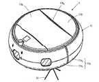
- FIG. 1is a perspective view showing a first embodiment of the self-propelled electronic device according to the present invention
- FIG. 2is an explanatory diagram of a ventilation path inside the self-propelled electronic device of the first embodiment.
- 3is a block diagram illustrating a control system of the self-propelled electronic device according to the first embodiment
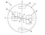
- FIG. 4is a plan layout diagram of a plurality of batteries in the self-propelled electronic device according to the first embodiment.
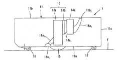
- FIG. 3is a side view of a plurality of batteries in the self-propelled electronic device according to the first embodiment.
- a self-propelled cleaneris illustrated as a self-propelled electronic device in each following embodiment including Embodiment 1, this invention is not limited to a self-propelled cleaner.
- the self-propelled cleaner 1 of the first embodimentsucks air containing dust on the floor surface F while self-propelling the floor surface F at the place where it is installed, and exhausts the air from which the dust has been removed. It is comprised so that F may be cleaned.
- This self-propelled cleaner 1includes a disk-shaped housing 11, and an electric blower as a rotating brush (not shown), a side brush 12, a dust collecting unit 13, and a suction unit inside and outside the housing 11.
- the housing 11is not limited to a disk shape, and may be a substantially triangular shape or a substantially quadrangular shape with rounded corners in plan view.
- the housing 11includes a bottom plate 11a having a circular shape in plan view having a suction port 11a 1 , a top plate 11b having a circular shape in plan view having an opening / closing lid 11b 1 and an exhaust port 11b 2 formed at a rear position of the opening / closing lid 11b 1. And a side plate 11c having an annular shape in plan view provided along the outer peripheral portions of the bottom plate 11a and the top plate 11b.
- the bottom plate 11ais provided with a front wheel 16, a pair of left and right drive wheels 15 and a pair of left and right rear wheels 17 that can swing around a vertical axis.
- the side plate 11chas a side plate front portion 11c 1 and a side plate rear portion 11c 2 which are substantially divided into front and rear, and the side plate front portion 11c 1 has a bumper function to alleviate an impact at the time of collision.
- suction passage 11a 2that connects the suction port 11a 1 and the dust collecting part 13, air passage 14a 1 for connecting the dust collection unit 13 and the electric blower 14a, the electric blower 14a exhaust and air passage 14a 2 that connects the mouth 11b 2 are provided.
- the pair of left and right drive wheels 15are provided so as to be rotatable around the same axis S parallel to the bottom plate 11a of the housing 11.
- the housing 11advances and retreats.
- the casing 2turns stationary.
- the rotation shafts of the drive wheels 15are connected so that rotational power can be obtained individually from the travel motors 16a, and the travel motors 16a are fixed to the bottom plate 11a of the housing 11 directly or via a suspension mechanism. ing.
- the rotating brush(not shown) is provided in the suction port 11a 1 so as to be rotatable around an axis parallel to the bottom plate 11a of the housing 11. Further, the left and right sides of the suction port 11a 1 in the bottom plate 11a the side brush 12 which rotates on the bottom plate 11a perpendicular axis around is provided.
- the rotating brushis formed by implanting a brush spirally on the outer peripheral surface of a roller that is a rotating shaft.
- the side brush 12has a rotating shaft and a plurality of brush bundles provided radially at the lower end of the rotating shaft.
- the rotating shaft of the rotating brush and the rotating shaft of the pair of side brushes 12are pivotally attached to a part of the bottom plate 11a of the housing 11, and include a brush drive motor, a pulley, a belt, and the like (not shown) provided in the vicinity thereof. It is connected independently through a power transmission mechanism or the like.
- a floor surface detection sensor(not shown) for detecting the floor surface F is disposed in front of the front wheel 16 and in front of the left and right drive wheels 15 in the bottom plate 11a of the housing 11.
- the detection signalis transmitted to the control unit, and the control unit controls each drive wheel 15 so as to travel while avoiding the descent staircase.
- the control unitis provided with a control board having a control circuit for controlling each element such as the drive wheel 15, the rotating brush, the side brush 12, and the electric blower 14 a in the self-propelled cleaner 1.
- a charging terminal (not shown) for charging the batteries 18 and 19is provided at the rear end of the side plate 11 c of the housing 11.
- the self-propelled cleaner 1 that cleans the room while travelingis returned to a charging stand (not shown) installed in the room. Thereby, a charging terminal contacts the terminal part provided in the charging stand, and the batteries 18 and 19 are charged.
- the charging stand connected to the commercial power source (outlet)is usually installed along the side wall of the room.
- the batteries 18 and 19are charged from a charging stand via a charging terminal, and supply electric power to each element such as a control board, driving wheel 15, rotating brush, side brush 12, electric blower 14a, and various sensors.
- the dust collection unit 13includes a dust collection box 13a having an introduction port connected to the suction passage 11a 2 and a discharge port connected to the upstream side ventilation passage (suction duct) 14a 1 of the electric blower 14a, and the dust collection box 13a. And a filter 13b detachably provided at the discharge port. Dust collecting box 13a are usually housed in the housing 11, when disposing the collected dust in the dust collecting box 13a is a dust collecting box 13a by opening the lid 11b 1 of the housing 11 Can be put in and out.
- the control part which performs operation control of the self-propelled cleaner 1 as a wholestores the control board having the control circuit constituted by the CPU 20 and other electronic components, and a storage for storing a travel map 21a.
- Unit 21motor driver 14b for driving the electric blower 14a, motor driver 16b for driving the traveling motor 16a of the drive wheel 15, human sensor 22a and its control unit 22b, contact sensor 23a and its control unit 23b, A floor surface sensor 24a and its control unit 24b are provided.
- the CPU 20is a central processing unit that transmits control signals to the motor drivers 14b and 16b individually based on program data stored in advance in the storage unit 21, and drives and controls the electric blower 14a and the traveling motor 16a. Perform a series of cleaning operations.
- the program dataincludes program data for a normal mode for cleaning a wide area of the floor surface F and for a wall-side mode for cleaning along the wall.
- the CPU 20receives a condition setting relating to the operation of the self-propelled cleaner 1 by the user from an operation panel (not shown) and stores it in the storage unit 21.
- the storage unit 21can store a travel map 21 a around the installation location of the self-propelled cleaner 1.
- the travel map 21ais information related to travel such as the travel route and travel speed of the self-propelled cleaner 1, and is stored in the storage unit 21 by the user in advance or during the cleaning operation of the self-propelled cleaner 1 itself. Can be recorded automatically.
- the human sensor 22afor example, a human sensor that detects the presence of a person using infrared rays, ultrasonic waves, visible light, or the like can be used.
- the human sensor 22ais disposed in a state exposed from the side plate 11c or the top plate 11b of the housing 11 to the outside.
- the CPU 20is connected to the human sensor 22a via the control unit 22b, and obtains presence information of persons around the outside of the housing 11 based on an output signal from the human sensor 22a.
- the contact sensor 23ais disposed, for example, in front of the side plate 11c of the housing 11 in order to detect that the self-propelled cleaner 1 has come into contact with an obstacle during traveling.
- the CPU 20is connected to the contact sensor 23a via the control unit 23b, and obtains presence information of obstacles around the outside of the housing 11 based on an output signal from the contact sensor 23a.
- the floor sensor 24ais disposed, for example, at the front and rear of the bottom plate 11a of the housing 11 in order for the self-propelled cleaner 1 to detect the descending staircase.
- the CPU 20is connected to the floor sensor 24a via the control unit 24b, and obtains information on the presence of down stairs around the outside of the housing 11 based on an output signal from the floor sensor 24a.
- the electric blower 14a, the drive wheel 15, the rotating brush (not shown), and the side brush 12are driven by a cleaning operation command.
- the housing 11is the floor F from the suction port 11a 1 while self predetermined range Inhale air containing dust.
- the dust on the floor surface Fis scraped up by the rotation of the rotating brush and guided to the suction port 11a 1 .
- the dust on the side of the suction port 11a 1is guided to the suction port 11a 1 by the rotation of the side brush 12.
- the air containing dust sucked into the housing 11 from the suction port 11a 1passes through the suction path 11a 2 of the housing 11 and flows into the dust collection box 13a.
- Airflow flowing into the dust collecting box 13ais discharged from the exhaust port 11b 2 is guided to the ventilation passage 14a 2 and flows through the filter 13b to the electric blower 14a to the outside.
- dust contained in the airflow in the dust collection box 13ais captured by the filter 13b, dust accumulates in the dust collection box 13a.
- the self-propelled cleaner 1moves stationary by rotating the left and right drive wheels 15 forward in the same direction, moving backward in the same direction, moving backward, and rotating in opposite directions.
- the driving wheel 15stops and the left and right driving wheels 15 rotate in opposite directions to each other. change.
- the self-propelled cleaner 1can be self-propelled while avoiding obstacles in the entire installation place or the entire desired range.
- the self-propelled cleaner 1is grounded at five points of the left and right drive wheels 15, the front wheel 16, and the left and right rear wheels 17, and the rear wheel 17 is lifted from the floor surface F even if it stops suddenly when moving forward. There is no. Therefore, it is prevented that the self-propelled cleaner 1 stops suddenly before the descending stairs while moving forward, and the self-propelled cleaner 1 is tilted forward and falls to the descending stairs.
- the drive wheel 15is formed by fitting a rubber tire having a groove into the wheel so as not to slip even if suddenly stopped.
- the self-propelled cleaner 1returns to the charging stand when cleaning is completed. Thereby, a charging terminal contacts a terminal part and a battery is charged.
- An operation unit(not shown) is provided on the upper surface of the self-propelled cleaner 1, and a cleaning operation can be executed by the operation unit.
- a receiving unitmay be provided in the housing 11 and a transmitter that transmits a command signal to the receiving unit may be provided so that the remote controller can be operated.
- a command signalmay be transmitted to the self-propelled cleaner 1 from a mobile phone called a smartphone via an Internet line and a router provided in the room so that it can be remotely operated.
- the two batteries 18, 19are arranged such that their centers of gravity G 1, G 2 are at a front position and a rear position with respect to the same axis S in the left-right direction in the housing 11. Moreover, the distance L1 between the center of gravity G1 of the front battery 18 and the stationary turning center point P and the distance L2 between the center of gravity G2 of the rear battery 19 and the stationary turning center point P are set to be the same in plan view. ing. That is, the centers of gravity G1 and G2 of the front and rear batteries 18 and 19 are symmetrically arranged in the front-rear direction around the stationary turning center point P.
- the two batteries 18 and 19By arranging the two batteries 18 and 19 in this way, the two batteries 18 and 19 which are heavy objects are arranged in a well-balanced manner in the front and rear in the housing 11, and the self-propelled cleaner 1 is placed on the traveling road surface.
- the power of the pair of left and right drive wheels 15can be efficiently transmitted to the step when climbing over the step (for example, the step between the flooring and the carpet), and the step over performance is improved.
- the distance between the center of gravity G1, G2 of the two batteries 18, 19 and the stationary turning center point Pis set to be the same, it is advantageous for the stationary turning property of the self-propelled cleaner 1.
- the two batteries 18 and 19are in the middle of a straight line K connecting the centroids G1 and G2 of the two batteries 18 and 19 in a plan view.
- a predetermined radius area Einner circle area indicated by a dotted line
- This regioncan be defined as a range in which the stationary turning property of the self-propelled cleaner 1 can be maintained satisfactorily.
- itis about 20% or less with respect to the distance (in this case, radius R) from the stationary turning center point P to the outer peripheral surface of the housing 11. is there.
- the straight line L1passes through the stationary turning center point P and the straight line K extends in a direction orthogonal to the same axis S in plan view. That is, the straight line K coincides with the center line C in the front-rear direction in the direction orthogonal to the same axis S in plan view.
- the two batteries 18 and 19are arranged in the middle of the case 11 in the left-right direction, so that the left and right drive wheels 15 are weighted in a balanced manner, As a result, it is possible to suppress the self-propelled cleaner 1 from climbing over the step in an oblique direction, and it is possible to maintain good straightness when overcoming the step.
- the two batteries 18 and 19are, for example, flat rectangular parallelepiped shapes, and their respective centers of gravity G1 and G2 are approximately near the bottom plate 11a of the housing 11. It is placed horizontally to be the same height. By placing the two batteries 18 and 19 horizontally, the center of gravity of the self-propelled cleaner 1 is lowered, which is advantageous in terms of running stability, stepping over property and stationary turning performance.
- FIG. 6is a side view of a plurality of batteries in the self-propelled electronic device according to the second embodiment.
- the same elements as those in FIG. 5are denoted by the same reference numerals.
- the battery 19 of the rear battery 19is vertically placed except that the battery 19 is rotated by 90 ° around the left and right axial centers. It is the same.
- the center of gravity G2 of the rear battery 19is higher than the center of gravity G1 of the front battery 18, but the two batteries 18 and 19 are arranged in the casing 11 in a well-balanced manner in the front, rear, left and right.
- the self-propelled cleaner 101 according to the second embodimentis configured in this manner, substantially the same effects as those of the first embodiment (step climbing ability, straightness after stepping over, step turning ability and running stability) can be obtained.
- the space before and after the battery 19can be widened.
- FIG. 7is a plan layout view of a plurality of batteries in the self-propelled electronic device of the third embodiment.
- the same elements as those in FIG. 4are denoted by the same reference numerals.
- the distance L2 between the center of gravity G2 of the rear battery 19 and the stationary turning center point Pis the center of gravity G1 of the front battery 18 and the stationary turning center. Except for being shorter than the distance L1 with the point P, it is the same as in the first embodiment.
- the intermediate point Q of the straight line K connecting the centroids G1 and G2 of the two batteries 18 and 19is shifted forward from the stationary turning center point P in a predetermined radius area E in plan view. It is settled. Even if the self-propelled cleaner 201 of the third embodiment is configured in this way, substantially the same effects as those of the first embodiment (step climbing ability, straightness after stepping over, step turning ability and running stability) can be obtained. The space behind the rear battery 19 can be widened.
- FIG. 8is a plan layout view of a plurality of batteries in the self-propelled electronic device of the fourth embodiment.
- the same elements as those in FIG. 4are denoted by the same reference numerals.
- the center of gravity G1 of the front battery 18 and the center of gravity G2 of the rear battery 19are centered on the center line C by an equal distance in plan view.
- the second embodimentis the same as the first embodiment except that the right and left sides are shifted. In this case, the intermediate point Q of the straight line K connecting the centroids G1 and G2 of the two batteries 18 and 19 coincides with the stationary turning center point P in plan view.
- the centers of gravity G1 and G2 of the front and rear batteries 18 and 19are symmetrically arranged on the front right side and the rear left side about the stationary turning center point P. Even if the self-propelled cleaner 301 of the fourth embodiment is configured in this manner, substantially the same effects as those of the first embodiment (step climbing ability, straight running after stepping, stationary turning ability and running stability) can be obtained.
- FIG. 9is a plan layout view of a plurality of batteries in the self-propelled electronic device of the fifth embodiment.
- the same elements as those in FIG. 4are denoted by the same reference numerals.
- the rear battery 19is rotated by 90 ° around the vertical axis in the plan view, and the center of gravity G2 of the rear battery 19 is set. It is the same as that of the fourth embodiment except that it is moved slightly to the left. In this case, the intermediate point Q of the straight line K connecting the centroids G1 and G2 of the two batteries 18 and 19 is shifted from the stationary turning center point P but is within the predetermined radius area E in plan view. .
- the center of gravity G1 and G2 of the front and rear batteries 18 and 19are arranged at asymmetric positions with respect to the stationary turning center point P in plan view. Since the intermediate point Q of the straight line K is within the predetermined radius area E, substantially the same effects as those of the first embodiment (step climbability, straight travel after step climbing, stationary turning performance, and running stability) can be obtained. In the case of the fifth embodiment, since the center of gravity G1 of the front battery 18 is closer to the center line C than the center of gravity G2 of the front battery 19, the straightness after overcoming the step is maintained and the rear battery 19 The right side space can be widened.
- FIG. 10is a plan layout view of components of the self-propelled electronic device according to the sixth embodiment.
- the same elements as those in FIGS. 2 to 4are denoted by the same reference numerals.
- the sixth embodimentwill specifically explain how the two batteries 18 and 19 are arranged together with the components such as the dust collecting unit 113 and the electric blower 114a.
- the housing 511when viewed in plan, has a shape with a circular front end portion as a flat surface, and left and right side brushes 112 and motors for side brushes at the left and right positions on the front end side of the bottom plate 111a.
- 112m and left and right floor surface detection sensors 124are provided, a front wheel 116 is provided at the left and right intermediate position on the front end side of the bottom plate 111a, and a floor surface detection sensor 125 is also provided at the left and right intermediate position on the rear end side of the bottom plate 111a.
- the rear wheels 117are provided on the left and right sides of the floor detection sensor 125.
- the bottom plate 111ain plan view, left and right driving wheels 115 and motor unit 115m driving wheel including motor 115m 1 is provided in the lateral direction of the same axis on S, the left and right drive wheel motor unit between 115m inlet 111a 1 is provided, the bearing portions of the right and left rotatably holding both ends of the rotating brush (not shown) to the right and left end portions of the inlet 111a 1 (not shown) is provided, the left A rotary brush motor 126 is provided in front of the bearing portion, and an output shaft of the rotary brush motor 126 and one end of the rotary brush are connected by a pulley and a timing belt (not shown).
- the electric blower 114a and a dust collecting portion 113 connected at a rear portion of the left side and the duct (not shown) on the right sideare provided, these are between the inlet 111a 1 and the dust collecting part 113
- a duct 127 to be connectedis provided, and two batteries 18 and 19 are provided at the front and rear positions of the same axis S. These batteries 18 and 19 are disposed at the positions described in the fifth embodiment (FIG. 9).
- the center of gravity G1, G2 of the front and rear batteries 18, 19is asymmetric with respect to the stationary turning center point P in plan view. Is located at a certain position, but the intermediate point Q of the straight line K connecting the centers of gravity G1 and G2 is within the predetermined radius area E. And running stability are obtained.
- the motor 115m 1 of the left and right drive wheel motor units 115m and the left and right side brush motors 112m, which are heavy objects,are arranged in front of the same axis S, the left and right drive wheels 115 are separated from each other when overcoming the step. It is advantageous for efficiently transmitting power to the step.
- FIG. 11is a plan layout view of a plurality of batteries in the self-propelled electronic device of the seventh embodiment.
- the self-propelled cleaner 601 according to the seventh embodimentincludes three batteries 18, 19a, and 19b.
- the three batteries 18, 19 a, and 19 bare center points of a triangular area 3 ⁇ / b> E formed by a straight line that connects the centroids G ⁇ b> 1, G ⁇ b> 2, and G ⁇ b> 3 of the three batteries 18, 19 a, and 19 b in plan view.
- 3Ecis arranged so as to be within a predetermined radius area E centering on the stationary turning center point P of the housing 11.
- the battery 18 having the center of gravity G1 at a position overlapping with the center line Cis disposed in front of the same axis S, and the center of gravity is located on the left side of the center line C and the battery 19a having the center of gravity G2 on the right side of the center line C.
- a battery 19b having G3is arranged behind the same axis S, and the centers of gravity G1, G2, G3 of these three batteries 18, 19a, 19b are located at the apex of the equilateral triangle area 3E.
- the center position 3Ec of 3Ecoincides with the stationary turning center point P.
- the rear two batteries 19a and 19bare vertically arranged in order to secure a rear space in the housing 11.
- the center position 3Ec of the equilateral triangle area 3Emay be shifted from the stationary turning center point P as long as it falls within the predetermined radius area E.
- FIG. 12is a plan layout view of a plurality of batteries in the self-propelled electronic device of the eighth embodiment.
- symbolis attached
- the self-propelled cleaner 701 according to the eighth embodimentincludes four batteries 18a, 18b, 19a, and 19b.
- the four batteries 18a, 18b, 19a, 19bare formed by straight lines connecting the respective centers of gravity G1, G2, G3, G4 of the four batteries 18a, 18b, 19a, 19b in plan view. It arrange
- the four batteries 18a, 18b, 19a, and 19bare arranged at the center of gravity G1, G2, G3 at the apex position of the square area 4E having the center point 4Ec that coincides with the stationary turning center point P in plan view.
- G4 and four centroids G1, G2, G3, G4are arranged symmetrically with respect to the same axis P as the center line C.
- all four batteries 18a, 18b, 19a, and 19bare vertically arranged in order to secure a central space in the casing 11.
- the four batteries 18a, 18b, 19a, 19bare arranged in a well-balanced manner in the front, rear, left, and right, and substantially the same effect as the first embodiment (step-over ability) , Straightness after moving over a step, stationary turning performance and running stability).
- the center position 4Ec of the square area 4Emay be shifted from the stationary turning center point P as long as it falls within the predetermined radius area E.
- the self-propelled electronic device of the present inventionis not limited to a self-propelled cleaner, and can be applied to, for example, a self-propelled ion generator provided with an ion generator.
- the auxiliary wheelmay be only the front wheel or only the rear wheel. Further, instead of the front wheel or the rear wheel, a smooth convex portion may be provided on the bottom plate so that the step can be smoothly overcome. Further, although the rear wheels are paired, one may be used.
- the self-propelled electronic deviceincludes a housing, a pair of left and right drive wheels provided on the housing on the same axis in the left-right direction so as to travel the housing, and the drive wheels, respectively.
- a drive wheel motorfor rotational driving, a plurality of batteries for supplying power to the drive wheel motor, and at least one of a front position and a rear position of the casing with respect to the same axis in the left-right direction
- auxiliary wheelsAt each center of gravity of the plurality of batteries, at least one center of gravity is located at the front position and the other at least one center of gravity is located at the rear position with respect to the same axis in the left-right direction of the housing.
- the self-propelled electronic device of the present inventionmay be configured as follows, or may be appropriately combined.
- the drive wheelis configured to be capable of forward and reverse rotation so that the housing can be fixedly turned about a fixed turning center point.
- the number of the plurality of batteriesis two; When the two batteries are viewed in plan, an intermediate point of a straight line connecting the centers of gravity of the two batteries is within a predetermined radius area centered on the stationary turning center point of the casing. It may be arranged. According to this configuration, even if the positions of the centers of gravity of the two batteries are shifted in the left-right direction from the center line in the front-rear direction perpendicular to the same axis in the left-right direction, the two heavy batteries are not contained in the casing. Is arranged in a well-balanced manner. As a result, the self-propelled electronic device can be prevented from traveling in an oblique direction after overcoming the level difference to maintain straight traveling performance, and is advantageous in stationary turning performance.
- the drive wheelis configured to be able to rotate forward and backward so that the housing can turn stationary around a stationary turning center point
- the number of the plurality of batteriesis three or more;
- the three or more batterieshave a center position of a polygonal area formed by a straight line connecting the centroids of the three or more batteries as viewed in a plane, with the stationary turning center point of the casing as the center. You may arrange
- At least the battery at the front position of the plurality of batterieshas a front-rear position where the center of gravity of the battery at the front position passes through the stationary turning center point and is orthogonal to the same axial center in the left-right direction. You may arrange
- a suction portprovided in a bottom portion of the housing, a dust collecting unit provided in the housing to communicate with the suction port, and provided in the housing to communicate with the dust collecting unit.
- An electric blowerThe drive wheel motor may be disposed at a position ahead of the same axis in the left-right direction, and the electric blower may be disposed at a position behind the same axis in the left-right direction. According to this configuration, it is possible to improve the step-over property, the straightness after moving over the step, and the stationary turning property of the self-propelled cleaner provided with a plurality of batteries as a self-propelled electronic device.
Landscapes
- Engineering & Computer Science (AREA)
- Aviation & Aerospace Engineering (AREA)
- Radar, Positioning & Navigation (AREA)
- Remote Sensing (AREA)
- Physics & Mathematics (AREA)
- General Physics & Mathematics (AREA)
- Automation & Control Theory (AREA)
- Mechanical Engineering (AREA)
- Electric Vacuum Cleaner (AREA)
Abstract
Description
Translated fromJapanese本発明は自走式電子機器に関する。The present invention relates to a self-propelled electronic device.
従来の自走式電子機器として、例えば特許文献1には、前後中間位置の左右方向の同一軸心上に配置された左右一対の駆動輪と、首振り自在な後輪と、左右一対の駆動輪の内側部分に配置された左右一対のバッテリーとを備えた自走式電気掃除機が開示されている。
また、特許文献2には、前後中間位置の左右方向の同一軸心上に配置された左右一対の駆動輪と、首振り自在な左右一対の後輪と、各後輪の上方に配置された左右一対のバッテリーとを備えた自走式電気掃除機が開示されている。As a conventional self-propelled electronic device, for example,
Further, in Patent Document 2, a pair of left and right drive wheels disposed on the same axial center in the left-right direction at the front-rear intermediate position, a pair of left and right rear wheels swingable, and disposed above each rear wheel A self-propelled electric vacuum cleaner including a pair of left and right batteries is disclosed.
特許文献1および2の自走式電気掃除機の場合、重量物である吸込ファン(電動送風機)が筐体の後部に配置されており、自走式電気掃除機全体の重心が左右一対の駆動輪よりも後方エリアに位置することになり、特に特許文献2では全体の重心が後端部付近となるため、走行路面上の段差(例えば、フローリングと絨毯との間の段差)を乗り越える際に左右一対の駆動輪の動力を段差に効率よく伝えることが構造的に難しい。In the case of the self-propelled vacuum cleaners of
また、清掃エリアの拡大に伴う清掃可能時間の延長のためにバッテリーの個数がさらに増加した場合、自走式電気掃除機の段差乗り越え性を考慮して重量物である複数個のバッテリーをバランスよく配置することが要求される。
さらに、自走式電気掃除機を含む自走式電子機器では、左右方向の同一軸心上に配置された左右一対の駆動輪が正逆回転して定置旋回する際、左右方向の同一軸心上に定置旋回中心点が位置し、電気掃除機全体の重心が定置旋回中心点に近いほど定置旋回に有利となるため、定置旋回性も考慮して複数個のバッテリーをバランスよく配置することも要求される。In addition, if the number of batteries further increases due to the extension of the cleaning time due to the expansion of the cleaning area, a plurality of heavy batteries should be balanced in consideration of the step-over capability of the self-propelled vacuum cleaner. It is required to be placed.
Further, in self-propelled electronic devices including self-propelled vacuum cleaners, when a pair of left and right drive wheels arranged on the same axis in the left-right direction rotate in the forward and reverse directions and turn stationary, the same axis in the left-right direction Since the stationary swivel center point is located on the top and the center of gravity of the entire vacuum cleaner is closer to the stationary swivel center point, it is more advantageous for stationary swivel. Required.
本発明は、このような課題に鑑みなされたものであり、運転可能時間の延長および段差乗り越え性の向上を図ることができ、さらには定置旋回性も向上させることができる自走式電子機器を提供することを目的とする。The present invention has been made in view of such a problem, and can provide a self-propelled electronic device capable of extending the drivable time and improving step climbability, and further improving stationary turning performance. The purpose is to provide.
かくして、本発明によれば、筐体と、前記筐体を走行させるように左右方向の同一軸心上にかつ前記筐体に設けられた左右一対の駆動輪と、前記駆動輪をそれぞれ回転駆動する駆動輪用モータと、前記駆動輪用モータに電力を供給する複数のバッテリーと、前記左右方向の同一軸心に対して前記筐体の前方位置および後方位置の少なくとも一方に設けられた補助輪とを備え、
前記複数のバッテリーは、前記複数のバッテリーのそれぞれの重心において前記筐体の前記左右方向の同一軸心に対して少なくとも一つの重心が前方位置となりかつその他の少なくとも一つの重心が後方位置となるように、配置されている自走式電子機器が提供される。Thus, according to the present invention, the casing, the pair of left and right drive wheels provided on the casing on the same axis in the left-right direction so as to travel the casing, and the drive wheels are driven to rotate. Driving wheel motor, a plurality of batteries for supplying electric power to the driving wheel motor, and an auxiliary wheel provided at at least one of a front position and a rear position of the casing with respect to the same axis in the left-right direction And
In the plurality of batteries, at least one center of gravity is a front position and the other at least one center of gravity is a rear position with respect to the same axis in the left-right direction of the housing at the center of gravity of each of the plurality of batteries. A self-propelled electronic device is provided.
本発明の自走式電子機器によれば、複数のバッテリーのそれぞれの重心において筐体の左右方向の同一軸心に対して少なくとも一つの重心が前方位置となりかつその他の少なくとも一つの重心が後方位置となるように配置されているため、自走式電子機器全体の重心が、平面的に視て、左右方向の同一軸心付近に配置されることとなる。
この結果、重量物である複数個のバッテリーが筐体内にバランスよく配置され、自走式電子機器が走行路面上の段差(例えば、フローリングと絨毯との間の段差)を乗り越える際に左右一対の駆動輪の動力を段差に効率よく伝えることができ、段差乗り越え性能が向上する。According to the self-propelled electronic device of the present invention, at least one center of gravity is a front position and the other at least one center of gravity is a rear position at the center of gravity of each of the plurality of batteries with respect to the same axial center in the left-right direction of the housing. Therefore, the center of gravity of the entire self-propelled electronic device is arranged in the vicinity of the same axis in the left-right direction as viewed in a plan view.
As a result, a plurality of heavy batteries are arranged in a balanced manner in the housing, and when the self-propelled electronic device gets over a step on the road surface (for example, a step between a flooring and a carpet), a pair of left and right The power of the drive wheels can be efficiently transmitted to the steps, and the overstep performance is improved.
(実施形態1)
図1は本発明に係る自走式電子機器の実施形態1を示す斜視図であり、図2は実施形態1の自走式電子機器の内部における通風経路の説明図である。また、図3は実施形態1の自走式電子機器の制御系を説明するブロック図であり、図4は実施形態1の自走式電子機器における複数のバッテリーの平面配置図であり、図5は実施形態1の自走式電子機器における複数のバッテリーの側面配置図である。なお、実施形態1を含む以下の各実施形態では自走式電子機器として自走式掃除機の場合を例示するが、本発明は自走式掃除機に限定されるものではない。(Embodiment 1)
FIG. 1 is a perspective view showing a first embodiment of the self-propelled electronic device according to the present invention, and FIG. 2 is an explanatory diagram of a ventilation path inside the self-propelled electronic device of the first embodiment. 3 is a block diagram illustrating a control system of the self-propelled electronic device according to the first embodiment, and FIG. 4 is a plan layout diagram of a plurality of batteries in the self-propelled electronic device according to the first embodiment. FIG. 3 is a side view of a plurality of batteries in the self-propelled electronic device according to the first embodiment. In addition, although the case of a self-propelled cleaner is illustrated as a self-propelled electronic device in each following
実施形態1の自走式掃除機1は、設置された場所の床面Fを自走しながら、床面F上のダストを含む空気を吸い込み、ダストを除去した空気を排気することにより床面F上を掃除するように構成されている。
この自走式掃除機1は、円盤形の筐体11を備え、この筐体11の内部および外部に、回転ブラシ(不図示)、サイドブラシ12、集塵部13、吸引部としての電動送風機14a、電動送風機14a用のモータドライバ14b、左右方向の同一軸心S上に設けられた左右一対の駆動輪15、左右一対の駆動輪15用の一対の走行モータ16a、一対の走行モータ16a用のモータドライバ16b、補助輪としての前輪16および後輪17、2個のバッテリー18、19、各種センサを含む制御部等の構成要素が設けられている。なお、筐体11は円盤形に限定されず、平面的に視て角部が丸い略三角形または略四角形等でもよい。The self-propelled
This self-propelled
筐体11は、吸込口11a1を有する平面視円形の底板11aと、開閉蓋11b1およびこの開閉蓋11b1の後方位置に形成された排気口11b2を有する平面視円形の天板11bと、底板11aおよび天板11bの外周部に沿って設けられた平面視円環形の側板11cとを備えている。底板11aには垂直軸心を中心に首振り可能な前輪16、左右一対の駆動輪15および左右一対の後輪17が設けられている。側板11cは、前後にほぼ二分された側板前部11c1と側板後部11c2とを有し、側板前部11c1は衝突時の衝撃を緩和するバンパー機能を備えている。The
また、筐体11内には、吸引口11a1と集塵部13とを接続する吸引路11a2と、集塵部13と電動送風機14aとを接続する通風路14a1、電動送風機14aと排気口11b2とを接続する通風路14a2とが設けられている。Also within
左右一対の駆動輪15は、筐体11の底板11aと平行な同一軸心S廻りに回転可能に設けられており、左右一対の駆動輪15が同一方向に回転すると筐体11が進退し、各駆動輪15が逆方向に同一速度で回転すると筐体2が定置旋回する。
各駆動輪15の回転軸は、各走行モータ16aからそれぞれ個別に回転力が得られるように連結されており、各走行モータ16aは筐体11の底板11aに直接またはサスペンション機構を介して固定されている。The pair of left and
The rotation shafts of the
図示しない前記回転ブラシは、筐体11の底板11aと平行な軸心廻りに回転可能に吸込口11a1に設けられている。また、底板11aにおける吸込口11a1の左右両側には底板11aと垂直な軸心廻りに回転する前記サイドブラシ12が設けられている。回転ブラシは、回転軸であるローラの外周面に螺旋状にブラシを植設することにより形成されている。サイドブラシ12は、回転軸と、回転軸の下端に放射状に設けられた複数本のブラシ束を有している。回転ブラシの回転軸および一対のサイドブラシ12の回転軸は、筐体11の底板11aの一部に枢着されると共に、その付近に設けられた図示しないブラシ駆動モータ、プーリおよびベルト等を含む動力伝達機構等を介して独立的に連結されている。The rotating brush (not shown) is provided in the
筐体11の底板11aにおける前輪16の前方および左右の駆動輪15の前方には床面Fを検知する図示しない床面検知センサが配置されている。床面検知センサによって下り階段を検知すると、その検知信号が制御部に送信され、制御部が各駆動輪15に下り階段を回避して走行するように制御する。A floor surface detection sensor (not shown) for detecting the floor surface F is disposed in front of the
制御部には、自走式掃除機1における駆動輪15、回転ブラシ、サイドブラシ12、電動送風機14a等の各要素を制御する制御回路を有する制御基板が設けられている。
また、筐体11の側板11cの後端には、バッテリー18、19の充電を行う充電端子(不図示)が設けられている。室内を自走しながら掃除する自走式掃除機1は、室内に設置されている充電台(不図示)に帰還する。これにより、充電台に設けられた端子部に充電端子が接触し、バッテリー18、19の充電が行われる。商用電源(コンセント)に接続される充電台は、通常、室内の側壁に沿って設置される。
バッテリー18、19は、充電端子を介して充電台から充電され、制御基板、駆動輪15、回転ブラシ、サイドブラシ12、電動送風機14a、各種センサ等の各要素に電力を供給する。The control unit is provided with a control board having a control circuit for controlling each element such as the
A charging terminal (not shown) for charging the
The
集塵部13は、吸引路11a2と接続する導入口および電動送風機14aの上流側の通風路(吸引ダクト)14a1と接続する排出口を有する集塵ボックス13aと、集塵ボックス13aの前記排出口に着脱可能に設けられたフィルター13bとを有してなる。集塵ボックス13aは、通常、筐体11内に収納されており、集塵ボックス13a内に捕集されたダストを廃棄する際は、筐体11の蓋11b1を開いて集塵ボックス13aを出し入れすることができる。The
図3に示すように、自走式掃除機1全体の動作制御を行う制御部は、CPU20およびその他の電子部品で構成された前記制御回路を有する前記制御基板と、走行マップ21aを記憶する記憶部21、電動送風機14aを駆動するためのモータドライバ14b、駆動輪15の走行モータ16aを駆動するためのモータドライバ16b、人感センサ22aおよびその制御ユニット22b、接触センサ23aおよびその制御ユニット23b、床面センサ24aおよびその制御ユニット24b等を備えて構成される。As shown in FIG. 3, the control part which performs operation control of the self-propelled
CPU20は中央演算処理装置であり、記憶部21に予め記憶されたプログラムデータに基いて、モータドライバ14b、16bに個別に制御信号を送信し、電動送風機14aおよび走行モータ16aを駆動制御して、一連の掃除運転を行う。なお、プログラムデータには、床面Fの広い領域を清掃する通常モード用と、壁際に沿って清掃する壁際モード用のプログラムデータが含まれる。また、CPU20は、ユーザーによる自走式掃除機1の動作に係る条件設定を操作パネル(図示省略)から受け付けて記憶部21に記憶させる。この記憶部21は、自走式掃除機1の設置場所周辺の走行マップ21aを記憶することができる。走行マップ21aは、自走式掃除機1の走行経路や走行速度などといった走行に係る情報であり、予めユーザーによって記憶部21に記憶させるか、あるいは自走式掃除機1自体が掃除運転中に自動的に記録することができる。The
人感センサ22aとしては、例えば、赤外線、超音波、可視光等によって人の存在を検知する人感センサを用いることができる。自走式掃除機1の外部周辺の人の存在を検知するために、例えば、筐体11の側板11cまたは天板11bから外部へ露出した状態で人感センサ22aが配置される。CPU20は制御ユニット22bを介して人感センサ22aと接続されており、人感センサ22aからの出力信号に基づいて筐体11の外部周辺の人の存在情報を得る。As the
接触センサ23aは、自走式掃除機1が走行時に障害物と接触したことを検知するために、例えば、筐体11の側板11cの前部に配置される。CPU20は制御ユニット23bを介して接触センサ23aと接続されており、接触センサ23aからの出力信号に基づいて筐体11の外部周辺の障害物の存在情報を得る。The
床面センサ24aは、自走式掃除機1が下り階段を検知するために、例えば、筐体11の底板11aの前部および後部に配置される。CPU20は制御ユニット24bを介して床面センサ24aと接続されており、床面センサ24aからの出力信号に基づいて筐体11の外部周辺の下り階段の存在情報を得る。The
このように構成された自走式掃除機1において、掃除運転の指令により、電動送風機14a、駆動輪15、回転ブラシ(不図示)およびサイドブラシ12が駆動する。これにより、回転ブラシ、サイドブラシ12、駆動輪15、前輪16および後輪17が床面Fに接地した状態で、筐体11は所定の範囲を自走しながら吸込口11a1から床面Fのダストを含む空気を吸い込む。このとき、回転ブラシの回転によって床面F上のダストは掻き上げられて吸込口11a1に導かれる。また、サイドブラシ12の回転によって吸込口11a1の側方のダストが吸込口11a1に導かれる。In the self-propelled
吸込口11a1から筐体11内に吸い込まれたダストを含む空気は、筐体11の吸引路11a2を通り、集塵ボックス13a内に流入する。集塵ボックス13a内に流入した気流は、フィルター13bを通過して電動送風機14aに流入して通風路14a2に導かれて排気口11b2から外部へ排出される。この際、集塵ボックス13a内の気流に含まれるダストはフィルター13bによって捕獲されるため、集塵ボックス13a内にダストが堆積する。The air containing dust sucked into the
また、自走式掃除機1は、左右の駆動輪15が同一方向に正回転して前進し、同一方向に逆回転して後退し、互いに逆方向に回転することにより定置旋回する。例えば、自走式掃除機1は、掃除領域の周縁に到達した場合および進路上の障害物に衝突した場合、駆動輪15が停止し、左右の駆動輪15を互いに逆方向に回転して向きを変える。これにより、自走式掃除機1は、設置場所全体あるいは所望範囲全体に障害物を避けながら自走することができる。In addition, the self-propelled
また、自走式掃除機1は、左右の駆動輪15と前輪16と左右の後輪17の5点で接地しており、前進時に急停止しても後輪17が床面Fから浮き上がることはない。そのため、自走式掃除機1が前進中に下り階段の手前で急停止し、それによって自走式掃除機1が前のめりに傾いて下り階段へ落下するということが防止されている。なお、駆動輪15は、急停止してもスリップしないよう、溝を有するゴムタイヤをホイールに嵌め込んで形成されている。In addition, the self-propelled
自走式掃除機1は、掃除が終了すると充電台に帰還する。これにより、充電端子が端子部に接してバッテリーが充電される。
自走式掃除機1の上面には操作部(不図示)が設けられており、操作部によって掃除運転を実行させることができる。また、筐体11内に受信部を設けると共に、受信部に指令信号を発信する送信機を設けてリモコン操作できるようにしてもよい。また、スマートフォンと呼ばれる携帯電話からインターネット回線および室内に設けたルーターを介して指令信号を自走式掃除機1に送信して遠隔操作できるようにしてもよい。The self-propelled
An operation unit (not shown) is provided on the upper surface of the self-propelled
<バッテリーの配置について>
本発明において、2個のバッテリー18、19は、それらの重心G1、G2が筐体11における左右方向の同一軸心Sに対して前方位置および後方位置となるように、配置されている。しかも、平面的に視て、前のバッテリー18の重心G1と定置旋回中心点Pとの距離L1と、後のバッテリー19の重心G2と定置旋回中心点Pとの距離L2とは同じに設定されている。すなわち、前後のバッテリー18、19の重心G1、G2は定置旋回中心点Pを中心として前後に対称的に配置されている。<Battery arrangement>
In the present invention, the two
このように2個のバッテリー18、19を配置することにより、重量物である2個のバッテリー18、19が筐体11内に前後にバランスよく配置され、自走式掃除機1が走行路面上の段差(例えば、フローリングと絨毯との間の段差)を乗り越える際に左右一対の駆動輪15の動力を段差に効率よく伝えることができ、段差乗り越え性能が向上する。さらに、2個のバッテリー18、19の重心G1、G2と定置旋回中心点Pとの距離は同じに設定されているため、自走式掃除機1の定置旋回性に有利となっている。By arranging the two
具体的に実施形態1の場合、図4に示すように、2個のバッテリー18、19は、平面的に視て、2個のバッテリー18、19の重心G1、G2を結ぶ直線Kの中間点が筐体11の定置旋回中心点Pを中心とする所定半径エリアE内(点線で示された円内領域)に収まるように、配置されている。この領域は、自走式掃除機1の定置旋回性を良好に保てる範囲であることを定義することができる。一例としては、自走式掃除機1のサイズ、重量等にもよるが、定置旋回中心点Pから筐体11の外周面までの距離(この場合は半径R)に対して約20%以下である。Specifically, in the case of the first embodiment, as shown in FIG. 4, the two
さらに詳しく説明すると、実施形態1の場合、平面的に視て、直線L1が定置旋回中心点Pを通り、かつ直線Kが同一軸心Sと直交する方向に延びている。すなわち、直線Kは、平面的に視て、同一軸心Sと直交する方向の前後方向の中心線Cと一致している。
このように2個のバッテリー18、19を配置することにより、2個のバッテリー18、19が筐体11の左右方向の中間に配置されるため、左右の駆動輪15にバランスよく重量がかかり、その結果、自走式掃除機1が段差を斜め方向に乗り越えることを抑制することができ、段差乗り越え時の直進性を良好に保つことができる。More specifically, in the case of the first embodiment, the straight line L1 passes through the stationary turning center point P and the straight line K extends in a direction orthogonal to the same axis S in plan view. That is, the straight line K coincides with the center line C in the front-rear direction in the direction orthogonal to the same axis S in plan view.
By arranging the two
さらに実施形態1の場合、図4と図5に示すように、2個のバッテリー18、19は例えば扁平な直方体形であり、それらの各重心G1、G2が筐体11の底板11a付近にほぼ同じ高さとなるように横置きに配置されている。2個のバッテリー18、19を横置きとすることにより、自走式掃除機1全体の重心が低くなり、走行安定性、段差乗り越え性および定置旋回性に有利となる。Further, in the case of the first embodiment, as shown in FIGS. 4 and 5, the two
(実施形態2)
図6は実施形態2の自走式電子機器における複数のバッテリーの側面配置図である。なお、図6において、図5中の要素と同様の要素には同一の符号を付している。
図6に示すように、実施形態2の自走式掃除機101の場合、後方のバッテリー19のバッテリー19を左右軸心廻りに90°回転させた縦置きとしたこと以外は、実施形態1と同様である。
この場合、後のバッテリー19の重心G2が前のバッテリー18の重心G1よりも高くなるが、筐体11内に前後左右にバランスよく2個のバッテリー18、19が配置される。
実施形態2の自走式掃除機101をこのように構成しても、実施形態1とほぼ同じ効果(段差乗り越え性、段差乗り越え後の直進性、定置旋回性および走行安定性)が得られると共に、後のバッテリー19の前後スペースを広くすることができる。(Embodiment 2)
FIG. 6 is a side view of a plurality of batteries in the self-propelled electronic device according to the second embodiment. In FIG. 6, the same elements as those in FIG. 5 are denoted by the same reference numerals.
As shown in FIG. 6, in the case of the self-propelled
In this case, the center of gravity G2 of the
Even if the self-propelled
(実施形態3)
図7は実施形態3の自走式電子機器における複数のバッテリーの平面配置図である。なお、図7において、図4中の要素と同様の要素には同一の符号を付している。
図7に示すように、実施形態3の自走式掃除機201の場合、後のバッテリー19の重心G2と定置旋回中心点Pとの距離L2が、前のバッテリー18の重心G1と定置旋回中心点Pとの距離L1よりも短くなっていること以外は、実施形態1と同様である。
この場合、平面的に視て、2個のバッテリー18、19の各重心G1、G2を結ぶ直線Kの中間点Qは定置旋回中心点Pよりも前方にずれているが所定半径エリアE内に収まっている。
実施形態3の自走式掃除機201をこのように構成しても、実施形態1とほぼ同じ効果(段差乗り越え性、段差乗り越え後の直進性、定置旋回性および走行安定性)が得られると共に、後のバッテリー19の後方スペースを広くすることができる。(Embodiment 3)
FIG. 7 is a plan layout view of a plurality of batteries in the self-propelled electronic device of the third embodiment. In FIG. 7, the same elements as those in FIG. 4 are denoted by the same reference numerals.
As shown in FIG. 7, in the case of the self-propelled
In this case, the intermediate point Q of the straight line K connecting the centroids G1 and G2 of the two
Even if the self-propelled
(実施形態4)
図8は実施形態4の自走式電子機器における複数のバッテリーの平面配置図である。なお、図8において、図4中の要素と同様の要素には同一の符号を付している。
図8に示すように、実施形態4の自走式掃除機301の場合、平面的に視て、前のバッテリー18の重心G1と後のバッテリー19の重心G2が互いに等しい距離だけ中心線Cに対して右側と左側にずれたこと以外は、実施形態1と同様である。
この場合、平面的に視て、2個のバッテリー18、19の各重心G1、G2を結ぶ直線Kの中間点Qは定置旋回中心点Pと一致している。つまり、前後のバッテリー18、19の重心G1、G2は定置旋回中心点Pを中心として前方右側と後方左側に対称的に配置されている。
実施形態4の自走式掃除機301をこのように構成しても、実施形態1とほぼ同じ効果(段差乗り越え性、段差乗り越え後の直進性、定置旋回性および走行安定性)が得られる。(Embodiment 4)
FIG. 8 is a plan layout view of a plurality of batteries in the self-propelled electronic device of the fourth embodiment. In FIG. 8, the same elements as those in FIG. 4 are denoted by the same reference numerals.
As shown in FIG. 8, in the case of the self-propelled
In this case, the intermediate point Q of the straight line K connecting the centroids G1 and G2 of the two
Even if the self-propelled
(実施形態5)
図9は実施形態5の自走式電子機器における複数のバッテリーの平面配置図である。なお、図9において、図4中の要素と同様の要素には同一の符号を付している。
図9に示すように、実施形態5の自走式掃除機401の場合、平面的に視て、後のバッテリー19を上下軸心廻りに90°回転させ、かつ後のバッテリー19の重心G2をやや左側へ移動させたこと以外は、実施形態4と同様である。
この場合、平面的に視て、2個のバッテリー18、19の各重心G1、G2を結ぶ直線Kの中間点Qは定置旋回中心点Pからずれているが所定半径エリアE内に収まっている。(Embodiment 5)
FIG. 9 is a plan layout view of a plurality of batteries in the self-propelled electronic device of the fifth embodiment. In FIG. 9, the same elements as those in FIG. 4 are denoted by the same reference numerals.
As shown in FIG. 9, in the case of the self-propelled
In this case, the intermediate point Q of the straight line K connecting the centroids G1 and G2 of the two
実施形態5の自走式掃除機401のように、平面的に視て、前後のバッテリー18、19の各重心G1、G2が定置旋回中心点Pに対して非対称的な位置に配置されても、直線Kの中間点Qが所定半径エリアE内に収まっているため、実施形態1とほぼ同じ効果(段差乗り越え性、段差乗り越え後の直進性、定置旋回性および走行安定性)が得られる。
また、実施形態5の場合、前のバッテリー18の重心G1を前のバッテリー19の重心G2よりも中心線Cに近づけているため、段差乗り越え後の直進性が保たれると共に、後のバッテリー19の右側スペースを広くすることができる。As in the self-propelled
In the case of the fifth embodiment, since the center of gravity G1 of the
(実施形態6)
図10は実施形態6の自走式電子機器の構成要素の平面配置図である。なお、図10において、図2~図4中の要素と同様の要素には同一の符号を付している。
図10に示すように、実施形態6では具体的に集塵部113および電動送風機114a等の構成要素と共に2個のバッテリー18、19がどのように配置されるかを説明する。(Embodiment 6)
FIG. 10 is a plan layout view of components of the self-propelled electronic device according to the sixth embodiment. In FIG. 10, the same elements as those in FIGS. 2 to 4 are denoted by the same reference numerals.
As shown in FIG. 10, the sixth embodiment will specifically explain how the two
実施形態6の場合、平面的に視て、筐体511は円形の前端部分を平坦面とした形状であり、その底板111aの前端部側の左右位置に左右のサイドブラシ112およびサイドブラシ用モータ112mと左右の床面検知センサ124が設けられ、底板111aの前端部側の左右中間位置に前輪116が設けられ、底板111aの後端部側の左右中間位置にも床面検知センサ125が設けられ、この床面検知センサ125の左右に後輪117が設けられている。In the case of the sixth embodiment, when viewed in plan, the
また、底板111aには、平面的に視て、左右方向の同一軸心S上に左右の駆動輪115およびモータ115m1を含む駆動輪用モータユニット115mが設けられ、左右の駆動輪用モータユニット115mの間には吸込口111a1が設けられ、吸込口111a1の左右両端部には図示しない回転ブラシの両端部を回転可能に保持する左右の軸受部(不図示)が設けられ、左側の軸受部の前方には回転ブラシ用モータ126が設けられ、図示しないプーリおよびタイミングベルトにて回転ブラシ用モータ126の出力軸と回転ブラシの一端部とが連結されている。Further, the
また、筐体511内において、後部の左側と右側に図示しないダクトにて接続された電動送風機114aと集塵部113が設けられ、吸込口111a1と集塵部113との間にはこれらを接続するダクト127が設けられ、2個のバッテリー18、19が同一軸心Sの前後位置に設けられている。なお、これらのバッテリー18、19は実施形態5(図9)で説明した位置に配置されている。Further, in the
このように各構成部品が筐体511に組み込まれた自走式掃除機501では、平面的に視て、前後のバッテリー18、19の各重心G1、G2が定置旋回中心点Pに対して非対称的な位置に配置されているが、各重心G1、G2を結ぶ直線Kの中間点Qが所定半径エリアE内に収まっているため、良好な段差乗り越え性、段差乗り越え後の直進性、定置旋回性および走行安定性が得られる。しかも、重量物である左右の駆動輪用モータユニット115mのモータ115m1および左右のサイドブラシ用モータ112mが同一軸心Sよりも前に配置されているため、段差乗り越え時に左右の駆動輪115から段差へ効率よく動力を伝達するのに有利となっている。Thus, in the self-propelled
(実施形態7)
図11は実施形態7の自走式電子機器における複数のバッテリーの平面配置図である。なお、図11において、図4中の要素と同様の要素には同一の符号を付している。
実施形態7の自走式掃除機601は3個のバッテリー18、19a、19bを有している。
この場合、3個のバッテリー18、19a、19bは、平面的に視て、3個のバッテリー18、19a、19bの各重心G1、G2、G3を結ぶ直線によって形成される三角形エリア3Eの中心点3Ecが筐体11の定置旋回中心点Pを中心とする所定半径エリアE内に収まるように、配置されている。(Embodiment 7)
FIG. 11 is a plan layout view of a plurality of batteries in the self-propelled electronic device of the seventh embodiment. In FIG. 11, the same elements as those in FIG. 4 are denoted by the same reference numerals.
The self-propelled
In this case, the three
具体的には、中心線Cと重なる位置に重心G1を有するバッテリー18が同一軸心Sよりも前方に配置され、中心線Cの右側に重心G2を有するバッテリー19aと中心線Cの左側に重心G3を有するバッテリー19bが同一軸心Sよりも後方に配置され、これら3個のバッテリー18、19a、19bの各重心G1、G2、G3は正三角形エリア3Eの頂点に位置し、この正三角形エリア3Eの中央位置3Ecが定置旋回中心点Pと一致している。なお、実施形態7の場合、筐体11内に後部スペースを確保するために、後方の2個のバッテリー19a、19bは縦置きされている。Specifically, the
実施形態7の自走式掃除機601をこのように構成しても、3個のバッテリー18、19a、19bは前後左右にバランスよく配置され、実施形態1とほぼ同じ効果(段差乗り越え性、段差乗り越え後の直進性、定置旋回性および走行安定性)が得られる。
なお、実施形態7において、所定半径エリアE内に収まるのであれば正三角形エリア3Eの中央位置3Ecは定置旋回中心点Pからずれてもよい。Even if the self-propelled
In the seventh embodiment, the center position 3Ec of the
(実施形態8)
図12は実施形態8の自走式電子機器における複数のバッテリーの平面配置図である。なお、図において、図4中の要素と同様の要素には同一の符号を付している。
実施形態8の自走式掃除機701は4個のバッテリー18a、18b、19a、19bを有している。
この場合、4個のバッテリー18a、18b、19a、19bは、平面的に視て、4個のバッテリー18a、18b、19a、19bの各重心G1、G2、G3、G4を結ぶ直線によって形成される四角形エリア4Eの中央位置4Ecが筐体11の定置旋回中心点Pを中心とする所定半径エリアE内に収まるように、配置されている。(Embodiment 8)
FIG. 12 is a plan layout view of a plurality of batteries in the self-propelled electronic device of the eighth embodiment. In addition, in the figure, the same code | symbol is attached | subjected to the element similar to the element in FIG.
The self-propelled
In this case, the four
具体的には、4個のバッテリー18a、18b、19a、19bは、平面的に視て、定置旋回中心点Pと一致する中心点4Ecを有する正方形エリア4Eの頂点位置に重心G1、G2、G3、G4を有し、かつ中心線Cと同一軸心Pに対して4つの重心G1、G2、G3、G4が対称的に配置されている。なお、実施形態8の場合、筐体11内に中央スペースを確保するために、4個のバッテリー18a、18b、19a、19bは全て縦置きされている。Specifically, the four
実施形態8の自走式掃除機701をこのように構成しても、4個のバッテリー18a、18b、19a、19bは前後左右にバランスよく配置され、実施形態1とほぼ同じ効果(段差乗り越え性、段差乗り越え後の直進性、定置旋回性および走行安定性)が得られる。
なお、実施形態8において、所定半径エリアE内に収まるのであれば正方形エリア4Eの中央位置4Ecは定置旋回中心点Pからずれてもよい。Even if the self-propelled
In the eighth embodiment, the center position 4Ec of the
(他の実施形態)
1.本発明の自走式電子機器は自走式掃除機に限定されるものではなく、例えば、イオン発生装置を備える自走式イオン発生装置にも適用可能である。
2.本発明の自走式電子機器において、補助輪は前輪のみでもよく、後輪のみでもよい。また、前輪または後輪の替わりに、底板に滑らかな凸部を設けて、段差をスムーズに乗り越えることができるようにしてもよい。また、後輪は一対になっているが1個でもよい。(Other embodiments)
1. The self-propelled electronic device of the present invention is not limited to a self-propelled cleaner, and can be applied to, for example, a self-propelled ion generator provided with an ion generator.
2. In the self-propelled electronic device of the present invention, the auxiliary wheel may be only the front wheel or only the rear wheel. Further, instead of the front wheel or the rear wheel, a smooth convex portion may be provided on the bottom plate so that the step can be smoothly overcome. Further, although the rear wheels are paired, one may be used.
(まとめ)
本発明の自走式電子機器は、筐体と、前記筐体を走行させるように左右方向の同一軸心上にかつ前記筐体に設けられた左右一対の駆動輪と、前記駆動輪をそれぞれ回転駆動する駆動輪用モータと、前記駆動輪用モータに電力を供給する複数のバッテリーと、前記左右方向の同一軸心に対して前記筐体の前方位置および後方位置の少なくとも一方に設けられた補助輪とを備え、
前記複数のバッテリーのそれぞれの重心において前記筐体の前記左右方向の同一軸心に対して少なくとも一つの重心が前方位置となりかつその他の少なくとも一つの重心が後方位置となるように、配置されている。(Summary)
The self-propelled electronic device according to the present invention includes a housing, a pair of left and right drive wheels provided on the housing on the same axis in the left-right direction so as to travel the housing, and the drive wheels, respectively. A drive wheel motor for rotational driving, a plurality of batteries for supplying power to the drive wheel motor, and at least one of a front position and a rear position of the casing with respect to the same axis in the left-right direction With auxiliary wheels,
At each center of gravity of the plurality of batteries, at least one center of gravity is located at the front position and the other at least one center of gravity is located at the rear position with respect to the same axis in the left-right direction of the housing. .
本発明の自走式電子機器は、次のように構成されてもよく、それらが適宜組み合わされてもよい。
(1)前記駆動輪は前記筐体が定置旋回中心点を中心に定置旋回可能なように正逆回転可能に構成され、
前記複数のバッテリーの数が2個であり、
前記2個のバッテリーは、平面的に視て、前記2個のバッテリーの各重心を結ぶ直線の中間点が前記筐体の前記定置旋回中心点を中心とする所定半径エリア内に収まるように、配置されてもよい。
この構成によれば、2個のバッテリーの各重心の位置が左右方向の同一軸心と直交する前後方向の中心線から左右方向にずれたとしても、重量物である2個のバッテリーが筐体内にバランスよく配置される。この結果、自走式電子機器が段差を乗り越えた後の斜め方向への走行を抑制し直進性を維持することができ、かつ定置旋回性にも有利となる。The self-propelled electronic device of the present invention may be configured as follows, or may be appropriately combined.
(1) The drive wheel is configured to be capable of forward and reverse rotation so that the housing can be fixedly turned about a fixed turning center point.
The number of the plurality of batteries is two;
When the two batteries are viewed in plan, an intermediate point of a straight line connecting the centers of gravity of the two batteries is within a predetermined radius area centered on the stationary turning center point of the casing. It may be arranged.
According to this configuration, even if the positions of the centers of gravity of the two batteries are shifted in the left-right direction from the center line in the front-rear direction perpendicular to the same axis in the left-right direction, the two heavy batteries are not contained in the casing. Is arranged in a well-balanced manner. As a result, the self-propelled electronic device can be prevented from traveling in an oblique direction after overcoming the level difference to maintain straight traveling performance, and is advantageous in stationary turning performance.
(2)前記駆動輪は前記筐体が定置旋回中心点を中心に定置旋回可能なように正逆回転可能に構成され、
前記複数のバッテリーの数が3個以上であり、
前記3個以上のバッテリーは、平面的に視て、前記3個以上のバッテリーの各重心を結ぶ直線によって形成される多角形エリアの中央位置が前記筐体の前記定置旋回中心点を中心とする所定半径エリア内に収まるように、配置されてもよい。
この構成によれば、重量物である3個以上のバッテリーが筐体内にバランスよく配置されるため、自走式電子機器が段差を乗り越えた後の斜め方向への走行を抑制し直進性を維持することができ、かつ定置旋回性にも有利となる。(2) The drive wheel is configured to be able to rotate forward and backward so that the housing can turn stationary around a stationary turning center point,
The number of the plurality of batteries is three or more;
The three or more batteries have a center position of a polygonal area formed by a straight line connecting the centroids of the three or more batteries as viewed in a plane, with the stationary turning center point of the casing as the center. You may arrange | position so that it may be settled in a predetermined radius area.
According to this configuration, since three or more heavy batteries are placed in a well-balanced manner in the housing, the self-propelled electronic device is prevented from traveling in an oblique direction after overcoming a step and maintains straightness. This is advantageous in terms of stationary turning ability.
(3)前記複数のバッテリーのうちの少なくとも前方位置のバッテリーは、平面的に視て、前記前方位置のバッテリーの重心が前記定置旋回中心点を通りかつ前記左右方向の同一軸心と直交する前後方向の中心線と重なるように、配置されてもよい。
この構成によれば、自走式電子機器が段差を乗り越えた後の斜め方向への走行を抑制した直進性により一層有利となる。(3) At least the battery at the front position of the plurality of batteries has a front-rear position where the center of gravity of the battery at the front position passes through the stationary turning center point and is orthogonal to the same axial center in the left-right direction. You may arrange | position so that it may overlap with the centerline of a direction.
According to this configuration, the self-propelled electronic device is further advantageous due to the straight traveling performance that suppresses traveling in an oblique direction after overcoming the step.
(4)前記筐体の底部に設けられた吸込口と、前記吸込口と連通するよう前記筐体内に設けられた集塵部と、前記集塵部と連通するように前記筐体内に設けられた電動送風機とをさらに備え、
前記駆動輪用モータが前記左右方向の同一軸心よりも前方位置に配置されると共に、前記電動送風機が前記左右方向の同一軸心よりも後方位置に配置されてもよい。
この構成によれば、自走式電子機器としての複数個のバッテリーを備えた自走式掃除機の段差乗り越え性、段差を乗り越えた後の直進性および定置旋回性を向上させることができる。(4) A suction port provided in a bottom portion of the housing, a dust collecting unit provided in the housing to communicate with the suction port, and provided in the housing to communicate with the dust collecting unit. An electric blower
The drive wheel motor may be disposed at a position ahead of the same axis in the left-right direction, and the electric blower may be disposed at a position behind the same axis in the left-right direction.
According to this configuration, it is possible to improve the step-over property, the straightness after moving over the step, and the stationary turning property of the self-propelled cleaner provided with a plurality of batteries as a self-propelled electronic device.
なお、開示された実施の形態は、全ての点で例示であって制限的なものではないと考えられるべきである。本発明の範囲は上述の説明ではなくて特許請求の範囲によって示され、特許請求の範囲と均等の意味及び範囲内での全ての変更が含まれることが意図される。It should be understood that the disclosed embodiments are illustrative and non-restrictive in every respect. The scope of the present invention is defined by the terms of the claims, rather than the description above, and is intended to include any modifications within the scope and meaning equivalent to the terms of the claims.
1、501 自走式掃除機(自走式電子機器)
3E 三角形エリア(多角形エリア)
3Ec、4Ec 中央位置
4E 正方形エリア(多角形エリア)
11、511 筐体
11a、111a 底板(底部)
11a1、111a1 吸込口
13、113 集塵部
14a、114a 電動送風機
15、115 駆動輪
16、116 前輪(補助輪)
17、117 後輪(補助輪)
18、18a、18b、19、19a、19b バッテリー
115m1 駆動輪用モータ
C 中心線
E 所定半径エリア
G1、G2、G3、G4 重心
K 直線
P 定置旋回中心点
Q 中間点
S 同一軸心1,501 Self-propelled vacuum cleaner (self-propelled electronic equipment)
3E Triangle area (Polygon area)
3Ec,
11, 511
11a1 , 111a1 Suction port 13, 113
17, 117 Rear wheel (auxiliary wheel)
18, 18a, 18b, 19, 19a,
Claims (5)
Translated fromJapanese前記複数のバッテリーは、前記複数のバッテリーのそれぞれの重心において前記筐体の前記左右方向の同一軸心に対して少なくとも一つの重心が前方位置となりかつその他の少なくとも一つの重心が後方位置となるように、配置されていることを特徴とする自走式電子機器。A housing, a pair of left and right drive wheels provided on the housing on the same axis in the left-right direction so as to travel the housing, a drive wheel motor for rotating each of the drive wheels, A plurality of batteries for supplying electric power to the drive wheel motor, and auxiliary wheels provided at at least one of a front position and a rear position of the housing with respect to the same axis in the left-right direction,
In the plurality of batteries, at least one center of gravity is a front position and the other at least one center of gravity is a rear position with respect to the same axis in the left-right direction of the housing at the center of gravity of each of the plurality of batteries. A self-propelled electronic device characterized by being arranged in
前記複数のバッテリーの数が2個であり、
前記2個のバッテリーは、平面的に視て、前記2個のバッテリーの各重心を結ぶ直線の中間点が前記筐体の前記定置旋回中心点を中心とする所定半径エリア内に収まるように、配置されている請求項1に記載の自走式電子機器。The drive wheel is configured to be able to rotate forward and backward so that the casing can turn stationary around a stationary turning center point,
The number of the plurality of batteries is two;
When the two batteries are viewed in plan, an intermediate point of a straight line connecting the centers of gravity of the two batteries is within a predetermined radius area centered on the stationary turning center point of the casing. The self-propelled electronic device according to claim 1 arranged.
前記複数のバッテリーの数が3個以上であり、
前記3個以上のバッテリーは、平面的に視て、前記3個以上のバッテリーの各重心を結ぶ直線によって形成される多角形エリアの中央位置が前記筐体の前記定置旋回中心点を中心とする所定半径エリア内に収まるように、配置されている請求項1に記載の自走式電子機器。The drive wheel is configured to be able to rotate forward and backward so that the casing can turn stationary around a stationary turning center point,
The number of the plurality of batteries is three or more;
The three or more batteries have a center position of a polygonal area formed by a straight line connecting the centroids of the three or more batteries as viewed in a plane, with the stationary turning center point of the casing as the center. The self-propelled electronic device according to claim 1, wherein the self-propelled electronic device is disposed so as to be within a predetermined radius area.
前記駆動輪用モータが前記左右方向の同一軸心よりも前方位置に配置されると共に、前記電動送風機が前記左右方向の同一軸心よりも後方位置に配置されている請求項1~4のいずれか1つに記載の自走式電子機器。A suction port provided at a bottom of the housing; a dust collecting unit provided in the housing to communicate with the suction port; and an electric blower provided in the housing to communicate with the dust collecting unit And further comprising
The drive wheel motor is disposed at a position forward of the same axis in the left-right direction, and the electric blower is disposed at a position rearward of the same axis in the left-right direction. The self-propelled electronic device as described in one.
Priority Applications (1)
| Application Number | Priority Date | Filing Date | Title |
|---|---|---|---|
| JP2019570285AJPWO2019155667A1 (en) | 2018-02-09 | 2018-09-03 | Self-propelled electronic equipment |
Applications Claiming Priority (2)
| Application Number | Priority Date | Filing Date | Title |
|---|---|---|---|
| JP2018-022065 | 2018-02-09 | ||
| JP2018022065 | 2018-02-09 |
Publications (1)
| Publication Number | Publication Date |
|---|---|
| WO2019155667A1true WO2019155667A1 (en) | 2019-08-15 |
Family
ID=67548050
Family Applications (1)
| Application Number | Title | Priority Date | Filing Date |
|---|---|---|---|
| PCT/JP2018/032629CeasedWO2019155667A1 (en) | 2018-02-09 | 2018-09-03 | Self-propelled electronic device |
Country Status (3)
| Country | Link |
|---|---|
| JP (1) | JPWO2019155667A1 (en) |
| TW (1) | TW201934065A (en) |
| WO (1) | WO2019155667A1 (en) |
Citations (5)
| Publication number | Priority date | Publication date | Assignee | Title |
|---|---|---|---|---|
| JP2003304992A (en)* | 2002-04-17 | 2003-10-28 | Hitachi Ltd | Self-propelled vacuum cleaner |
| JP2014186449A (en)* | 2013-03-22 | 2014-10-02 | Kojima Press Industry Co Ltd | Unmanned carrier |
| JP2015075825A (en)* | 2013-10-07 | 2015-04-20 | シャープ株式会社 | Self-propelled electronic device |
| WO2016013365A1 (en)* | 2014-07-25 | 2016-01-28 | シャープ株式会社 | Autonomous vehicle |
| JP2016073396A (en)* | 2014-10-03 | 2016-05-12 | 株式会社マキタ | Self propelled dust collection robot |
- 2018
- 2018-09-03JPJP2019570285Apatent/JPWO2019155667A1/enactivePending
- 2018-09-03WOPCT/JP2018/032629patent/WO2019155667A1/ennot_activeCeased
- 2018-12-21TWTW107146571Apatent/TW201934065A/enunknown
Patent Citations (5)
| Publication number | Priority date | Publication date | Assignee | Title |
|---|---|---|---|---|
| JP2003304992A (en)* | 2002-04-17 | 2003-10-28 | Hitachi Ltd | Self-propelled vacuum cleaner |
| JP2014186449A (en)* | 2013-03-22 | 2014-10-02 | Kojima Press Industry Co Ltd | Unmanned carrier |
| JP2015075825A (en)* | 2013-10-07 | 2015-04-20 | シャープ株式会社 | Self-propelled electronic device |
| WO2016013365A1 (en)* | 2014-07-25 | 2016-01-28 | シャープ株式会社 | Autonomous vehicle |
| JP2016073396A (en)* | 2014-10-03 | 2016-05-12 | 株式会社マキタ | Self propelled dust collection robot |
Also Published As
| Publication number | Publication date |
|---|---|
| TW201934065A (en) | 2019-09-01 |
| JPWO2019155667A1 (en) | 2021-01-28 |
Similar Documents
| Publication | Publication Date | Title |
|---|---|---|
| JP6706770B2 (en) | Autonomous traveling vacuum cleaner | |
| JP6476077B2 (en) | Self-propelled electronic device and traveling method of the self-propelled electronic device | |
| KR101892652B1 (en) | Electric cleaner | |
| WO2013164924A1 (en) | Self-propelled electronic apparatus | |
| US10542858B2 (en) | Self-propelled electronic device and travel method for self-propelled electronic device | |
| JP6757575B2 (en) | Self-propelled vacuum cleaner | |
| JPWO2012147669A1 (en) | Electric vacuum cleaner | |
| JP6378984B2 (en) | Self-propelled vacuum cleaner | |
| JP6888847B2 (en) | Self-propelled vacuum cleaner | |
| JP2017213009A (en) | Autonomous travel type cleaner | |
| JP2015075825A (en) | Self-propelled electronic device | |
| CN207613718U (en) | A kind of electronic intelligence sweeping robot | |
| JP2003225184A (en) | Cleaning equipment | |
| CN218186638U (en) | Automatic cleaning equipment | |
| JP6462350B2 (en) | Self-propelled vacuum cleaner | |
| JP2016193242A (en) | Self-propelled electronic device | |
| JP6526930B2 (en) | Self-propelled electronic device and traveling method of the self-propelled electronic device | |
| WO2019155667A1 (en) | Self-propelled electronic device | |
| JP6289327B2 (en) | Self-propelled vacuum cleaner | |
| JP6263306B2 (en) | Self-propelled vacuum cleaner | |
| JP5909370B2 (en) | Self-propelled vacuum cleaner | |
| JP2016135303A (en) | Self-propelled vacuum cleaner | |
| JP6481079B1 (en) | Self-propelled vacuum cleaner | |
| JP6487996B2 (en) | Self-propelled vacuum cleaner | |
| JP6640603B2 (en) | Self-propelled vacuum cleaner |
Legal Events
| Date | Code | Title | Description |
|---|---|---|---|
| 121 | Ep: the epo has been informed by wipo that ep was designated in this application | Ref document number:18905475 Country of ref document:EP Kind code of ref document:A1 | |
| ENP | Entry into the national phase | Ref document number:2019570285 Country of ref document:JP Kind code of ref document:A | |
| NENP | Non-entry into the national phase | Ref country code:DE | |
| 122 | Ep: pct application non-entry in european phase | Ref document number:18905475 Country of ref document:EP Kind code of ref document:A1 |