WO2019142284A1 - Vehicle control device - Google Patents
Vehicle control deviceDownload PDFInfo
- Publication number
- WO2019142284A1 WO2019142284A1PCT/JP2018/001332JP2018001332WWO2019142284A1WO 2019142284 A1WO2019142284 A1WO 2019142284A1JP 2018001332 WJP2018001332 WJP 2018001332WWO 2019142284 A1WO2019142284 A1WO 2019142284A1
- Authority
- WO
- WIPO (PCT)
- Prior art keywords
- vehicle
- mode
- detection
- control
- level
- Prior art date
- Legal status (The legal status is an assumption and is not a legal conclusion. Google has not performed a legal analysis and makes no representation as to the accuracy of the status listed.)
- Ceased
Links
Images


Classifications
- B—PERFORMING OPERATIONS; TRANSPORTING
- B60—VEHICLES IN GENERAL
- B60W—CONJOINT CONTROL OF VEHICLE SUB-UNITS OF DIFFERENT TYPE OR DIFFERENT FUNCTION; CONTROL SYSTEMS SPECIALLY ADAPTED FOR HYBRID VEHICLES; ROAD VEHICLE DRIVE CONTROL SYSTEMS FOR PURPOSES NOT RELATED TO THE CONTROL OF A PARTICULAR SUB-UNIT
- B60W60/00—Drive control systems specially adapted for autonomous road vehicles
- B60W60/005—Handover processes
- B60W60/0053—Handover processes from vehicle to occupant
- B60W60/0055—Handover processes from vehicle to occupant only part of driving tasks shifted to occupants
- B—PERFORMING OPERATIONS; TRANSPORTING
- B60—VEHICLES IN GENERAL
- B60W—CONJOINT CONTROL OF VEHICLE SUB-UNITS OF DIFFERENT TYPE OR DIFFERENT FUNCTION; CONTROL SYSTEMS SPECIALLY ADAPTED FOR HYBRID VEHICLES; ROAD VEHICLE DRIVE CONTROL SYSTEMS FOR PURPOSES NOT RELATED TO THE CONTROL OF A PARTICULAR SUB-UNIT
- B60W30/00—Purposes of road vehicle drive control systems not related to the control of a particular sub-unit, e.g. of systems using conjoint control of vehicle sub-units
- B60W30/08—Active safety systems predicting or avoiding probable or impending collision or attempting to minimise its consequences
- B60W30/09—Taking automatic action to avoid collision, e.g. braking and steering
- B—PERFORMING OPERATIONS; TRANSPORTING
- B60—VEHICLES IN GENERAL
- B60W—CONJOINT CONTROL OF VEHICLE SUB-UNITS OF DIFFERENT TYPE OR DIFFERENT FUNCTION; CONTROL SYSTEMS SPECIALLY ADAPTED FOR HYBRID VEHICLES; ROAD VEHICLE DRIVE CONTROL SYSTEMS FOR PURPOSES NOT RELATED TO THE CONTROL OF A PARTICULAR SUB-UNIT
- B60W30/00—Purposes of road vehicle drive control systems not related to the control of a particular sub-unit, e.g. of systems using conjoint control of vehicle sub-units
- B60W30/10—Path keeping
- B60W30/12—Lane keeping
- B—PERFORMING OPERATIONS; TRANSPORTING
- B60—VEHICLES IN GENERAL
- B60W—CONJOINT CONTROL OF VEHICLE SUB-UNITS OF DIFFERENT TYPE OR DIFFERENT FUNCTION; CONTROL SYSTEMS SPECIALLY ADAPTED FOR HYBRID VEHICLES; ROAD VEHICLE DRIVE CONTROL SYSTEMS FOR PURPOSES NOT RELATED TO THE CONTROL OF A PARTICULAR SUB-UNIT
- B60W30/00—Purposes of road vehicle drive control systems not related to the control of a particular sub-unit, e.g. of systems using conjoint control of vehicle sub-units
- B60W30/18—Propelling the vehicle
- B60W30/18009—Propelling the vehicle related to particular drive situations
- B60W30/18163—Lane change; Overtaking manoeuvres
- B—PERFORMING OPERATIONS; TRANSPORTING
- B60—VEHICLES IN GENERAL
- B60W—CONJOINT CONTROL OF VEHICLE SUB-UNITS OF DIFFERENT TYPE OR DIFFERENT FUNCTION; CONTROL SYSTEMS SPECIALLY ADAPTED FOR HYBRID VEHICLES; ROAD VEHICLE DRIVE CONTROL SYSTEMS FOR PURPOSES NOT RELATED TO THE CONTROL OF A PARTICULAR SUB-UNIT
- B60W50/00—Details of control systems for road vehicle drive control not related to the control of a particular sub-unit, e.g. process diagnostic or vehicle driver interfaces
- B60W50/02—Ensuring safety in case of control system failures, e.g. by diagnosing, circumventing or fixing failures
- B60W50/0205—Diagnosing or detecting failures; Failure detection models
- B—PERFORMING OPERATIONS; TRANSPORTING
- B60—VEHICLES IN GENERAL
- B60W—CONJOINT CONTROL OF VEHICLE SUB-UNITS OF DIFFERENT TYPE OR DIFFERENT FUNCTION; CONTROL SYSTEMS SPECIALLY ADAPTED FOR HYBRID VEHICLES; ROAD VEHICLE DRIVE CONTROL SYSTEMS FOR PURPOSES NOT RELATED TO THE CONTROL OF A PARTICULAR SUB-UNIT
- B60W50/00—Details of control systems for road vehicle drive control not related to the control of a particular sub-unit, e.g. process diagnostic or vehicle driver interfaces
- B60W50/02—Ensuring safety in case of control system failures, e.g. by diagnosing, circumventing or fixing failures
- B60W50/029—Adapting to failures or work around with other constraints, e.g. circumvention by avoiding use of failed parts
- B—PERFORMING OPERATIONS; TRANSPORTING
- B60—VEHICLES IN GENERAL
- B60W—CONJOINT CONTROL OF VEHICLE SUB-UNITS OF DIFFERENT TYPE OR DIFFERENT FUNCTION; CONTROL SYSTEMS SPECIALLY ADAPTED FOR HYBRID VEHICLES; ROAD VEHICLE DRIVE CONTROL SYSTEMS FOR PURPOSES NOT RELATED TO THE CONTROL OF A PARTICULAR SUB-UNIT
- B60W50/00—Details of control systems for road vehicle drive control not related to the control of a particular sub-unit, e.g. process diagnostic or vehicle driver interfaces
- B60W50/08—Interaction between the driver and the control system
- B60W50/14—Means for informing the driver, warning the driver or prompting a driver intervention
- B—PERFORMING OPERATIONS; TRANSPORTING
- B62—LAND VEHICLES FOR TRAVELLING OTHERWISE THAN ON RAILS
- B62D—MOTOR VEHICLES; TRAILERS
- B62D6/00—Arrangements for automatically controlling steering depending on driving conditions sensed and responded to, e.g. control circuits
- B—PERFORMING OPERATIONS; TRANSPORTING
- B60—VEHICLES IN GENERAL
- B60W—CONJOINT CONTROL OF VEHICLE SUB-UNITS OF DIFFERENT TYPE OR DIFFERENT FUNCTION; CONTROL SYSTEMS SPECIALLY ADAPTED FOR HYBRID VEHICLES; ROAD VEHICLE DRIVE CONTROL SYSTEMS FOR PURPOSES NOT RELATED TO THE CONTROL OF A PARTICULAR SUB-UNIT
- B60W50/00—Details of control systems for road vehicle drive control not related to the control of a particular sub-unit, e.g. process diagnostic or vehicle driver interfaces
- B60W50/02—Ensuring safety in case of control system failures, e.g. by diagnosing, circumventing or fixing failures
- B60W50/0205—Diagnosing or detecting failures; Failure detection models
- B60W2050/0215—Sensor drifts or sensor failures
- B—PERFORMING OPERATIONS; TRANSPORTING
- B60—VEHICLES IN GENERAL
- B60W—CONJOINT CONTROL OF VEHICLE SUB-UNITS OF DIFFERENT TYPE OR DIFFERENT FUNCTION; CONTROL SYSTEMS SPECIALLY ADAPTED FOR HYBRID VEHICLES; ROAD VEHICLE DRIVE CONTROL SYSTEMS FOR PURPOSES NOT RELATED TO THE CONTROL OF A PARTICULAR SUB-UNIT
- B60W50/00—Details of control systems for road vehicle drive control not related to the control of a particular sub-unit, e.g. process diagnostic or vehicle driver interfaces
- B60W50/02—Ensuring safety in case of control system failures, e.g. by diagnosing, circumventing or fixing failures
- B60W50/029—Adapting to failures or work around with other constraints, e.g. circumvention by avoiding use of failed parts
- B60W2050/0295—Inhibiting action of specific actuators or systems
Definitions
- the present inventionrelates to a vehicle control device for performing, for example, automatic driving and driving assistance of a vehicle.
- sensorsmonitor specific directions or all directions of the vehicle with sensors, and according to the monitoring results, automatic driving of the vehicle at an appropriate route or speed. Control or assist the driver in driving.
- acceleration / deceleration control and steering controlare permitted.
- acceleration / deceleration control and steering controlare permitted.
- driving controlis prohibited and acceleration / deceleration control is permitted.
- proposalshave been made to prohibit acceleration / deceleration control and steering control (see Patent Document 1).
- the present inventionhas been made in view of the above-described conventional example, and it is an object of the present invention to provide a vehicle control device capable of further increasing the automation ratio of drive control or drive support while realizing safe drive control or drive support. I assume.
- the present inventionhas the following configuration.
- perimeter monitoring means(41, 42, 43) for performing perimeter monitoring of the host vehicle;
- the periphery monitoring means of the host vehicleIt is possible to detect targets on the side and rear of the host vehicle, When both the side and rear detection levels reach a predetermined level, the lateral control is not suppressed,
- a vehicle control apparatuscharacterized in that lateral control accompanied by the steering control is suppressed when at least one of the side and rear detection levels does not reach a predetermined level.
- FIG. 1is a view showing the configuration of a vehicle system of an autonomous driving vehicle according to the embodiment.
- FIG. 2Ais a view showing an example of a detection range by the autonomous driving vehicle according to the embodiment.
- FIG. 2Bis a view showing an example of a local map by the autonomous driving vehicle according to the embodiment.
- FIG. 3is a block diagram for automatic operation control.
- FIG. 4is a schematic view showing an example of action candidates under some circumstances.
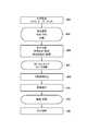
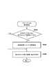
- FIG. 5is a flowchart showing the procedure of action candidate determination and route selection.
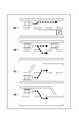
- FIG. 6is a flow chart showing a procedure of route selection when there is a lane change instruction by the driver.
- FIG. 7is a flowchart showing a procedure for changing the driving mode (driving level) in the autonomous driving vehicle.
- a driversets a destination from a navigation system mounted on a vehicle before traveling, and determines a route to the destination by a server or a navigation system.
- a vehicle control deviceor a drive control device configured by an ECU or the like of the vehicle drives the vehicle to a destination along the route.
- appropriate actionsare determined in a timely manner according to the external environment such as the route and the road condition, the driver's condition, etc., and drive control, steering control, braking control, etc. are performed to drive the vehicle. .
- These controlsmay be collectively referred to as travel control.
- the drivermay be alerting other than driving. This is done when the control is relatively easy, for example when following a leading vehicle in a traffic jam on a freeway.
- the driverdoes not have to have a handle, but needs to pay attention to the surrounding conditions and the like.
- This levelmay be applied, for example, when traveling while maintaining a lane on a freeway. This level may be referred to as a second mode in this example.
- the driver's attention to the surroundingscan be detected by the driver state detection camera 41a, and the holding of the steering wheel can be detected by the steering wheel grip sensor.
- the driverdoes not have to operate the steering wheel or the throttle, but needs to hold the steering wheel and pay attention to driving in preparation for takeover to the driver.
- This levelmay be applied, for example, to bifurcations and merging on highways. This level may be referred to as the first mode in this example.
- the automation ratedecreases more.
- the lowest levelis manual operation, but may include partially automated driving support, and in this example is one level of automatic operation.
- the above-described driving supportis a function that supports driving operation by a driver who is the main body of driving by monitoring the surrounding area or partial automation. For example, there is an automatic braking function that applies braking only if the front is monitored and detects a fault, a rear monitoring function that detects the vehicle behind diagonally and warns the driver, and a parking function to the parking space.
- the automatic driving levelmay be lowered to the level of the driving support to give priority to the driving operation by the driver. In that case, after the driver stops the operation, the automatic driving level may be reset according to the vehicle state and the external environment to continue the automatic driving.
- the steering operation in the present embodimentthere is a winker lever operation during traveling on a high speed road by automatic driving at an automation rate of the first mode or more described above.
- the traveling control unitconfigured by an ECU or the like performs control such as steering, braking, or driving while monitoring an obstacle or the like around the vehicle.
- the automatic driving level(or mode) is switched, that is notified from the vehicle to the driver by voice, display, vibration or the like.
- the driveris notified that the steering wheel may be released.
- the driveris notified to hold the handle. This notification is repeatedly issued until the handle grip sensor detects that the driver grips the handle. Then, for example, if the steering wheel is not gripped within the time limit or the limit point of mode switching, an operation such as stopping at a safe place may be performed. Automated operation is generally performed as described above, and the configuration and control therefor are described below.
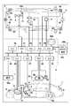
- FIG. 1is a block diagram of a control device for a vehicle according to an embodiment of the present invention, which controls a vehicle 1.
- the vehicle 1is schematically shown in a plan view and a side view.
- the vehicle 1is a sedan-type four-wheeled passenger car as an example.
- the control device of FIG. 1includes a control unit 2.
- the control unit 2includes a plurality of ECUs 20 to 29 communicably connected by an in-vehicle network.
- Each ECUincludes a processor represented by a CPU, a storage device such as a semiconductor memory, an interface with an external device, and the like.
- the storage devicestores programs executed by the processor, data used by the processor for processing, and the like.
- Each ECUmay include a plurality of processors, storage devices, interfaces, and the like.
- each of the ECUs 20 to 29 takes charge ofwill be described below.
- the number of ECUs and the functions to be in chargecan be appropriately designed for the vehicle 1, and can be subdivided or integrated as compared with the present embodiment.
- the ECU 20executes control related to automatic driving of the vehicle 1.
- automatic drivingat least one of steering of the vehicle 1 and acceleration / deceleration is automatically controlled.
- both steering and acceleration / decelerationare automatically controlled.
- the ECU 21controls the electric power steering device 3.
- the electric power steering apparatus 3includes a mechanism for steering the front wheels in response to a driver's driving operation (steering operation) on the steering wheel 31. Further, the electric power steering device 3 includes a motor for assisting a steering operation or a driving force for automatically steering the front wheels, a sensor for detecting a steering angle, and the like.
- the ECU 21automatically controls the electric power steering device 3 in response to an instruction from the ECU 20 to control the traveling direction of the vehicle 1.
- the ECUs 22 and 23perform control of detection units 41 to 43 for detecting the surrounding situation of the vehicle and perform information processing of detection results.
- the detection unit 41is a camera for capturing an image in front of the vehicle 1 (hereinafter, may be referred to as a camera 41), and in the case of the present embodiment, two are provided on the roof front of the vehicle 1. By analyzing the image captured by the camera 41, it is possible to extract the contour of the target and extract the lane line (white line etc.) on the road.
- the detection unit 41ais a camera for detecting the state of the driver (hereinafter may be referred to as the driver state detection camera 41a), and is installed so as to capture the expression of the driver and is not shown.
- the driver state detection camera 41aare connected to an ECU that processes the image data.
- the detection unit 42is a rider (Light Detection and Ranging or Laser Imaging Detection and Ranging) (hereinafter, may be referred to as a rider 42), detects a target around the vehicle 1, or detects a target with the target. Ranging the distance.
- a rider 42Light Detection and Ranging or Laser Imaging Detection and Ranging
- five lidars 42are provided, one at each of the front corners of the vehicle 1, one at the center of the rear, and one at each side of the rear.
- the detection unit 43is a millimeter wave radar (hereinafter, may be referred to as a radar 43), detects a target around the vehicle 1, and measures the distance to the target.
- five radars 43are provided, one at the center of the front of the vehicle 1 and one at each of the front corners, and one at each of the rear corners.
- the ECU 22performs control of one camera 41 and each lidar 42 and information processing of detection results.
- the ECU 23controls the other camera 42 and each radar 43 and performs information processing of detection results.
- the reliability of the detection resultscan be improved by providing two sets of devices for detecting the surrounding environment of the vehicle, and by providing different types of detection units such as cameras, lidars and radars, analysis of the environment around the vehicle Can be done in many ways.
- the ECU 24controls the gyro sensor 5, the GPS sensor 24b, and the communication device 24c, and performs information processing of a detection result or a communication result.
- the gyro sensor 5detects the rotational movement of the vehicle 1.
- the course of the vehicle 1can be determined from the detection result of the gyro sensor 5, the wheel speed, and the like.
- the GPS sensor 24 bdetects the current position of the vehicle 1.
- the communication device 24 cperforms wireless communication with a server that provides map information and traffic information, and acquires such information.
- the ECU 24can access a database 24a of map information built in a storage device, and the ECU 24 performs a route search from a current location to a destination.
- the ECU 25includes a communication device 25a for inter-vehicle communication.
- the communication device 25aperforms wireless communication with other vehicles in the vicinity to exchange information between the vehicles.
- the ECU 26controls the power plant 6.
- the power plant 6is a mechanism that outputs a driving force for rotating the drive wheels of the vehicle 1 and includes, for example, an engine and a transmission.
- the ECU 26controls, for example, the output of the engine in response to the driver's driving operation (acceleration operation or acceleration operation) detected by the operation detection sensor 7a provided on the accelerator pedal 7A, the vehicle speed detected by the vehicle speed sensor 7c, etc.
- the gear position of the transmissionis switched based on the information of.
- the ECU 26automatically controls the power plant 6 in response to an instruction from the ECU 20 to control acceleration / deceleration of the vehicle 1.
- the ECU 27controls a lamp (headlight, taillight, etc.) including the direction indicator 8.
- the turn indicator 8is provided at the front, the door mirror and the rear of the vehicle 1.
- the ECU 28controls the input / output device 9.
- the input / output device 9outputs information to the driver and accepts input of information from the driver.
- the voice output device 91reports information to the driver by voice.
- the display device 92notifies the driver of the information by displaying an image.
- the display device 92is disposed, for example, on the surface of the driver's seat, and constitutes an instrument panel or the like.
- voice and a displaywere illustrated here, you may alert
- the input device 93is arranged at a position where the driver can operate, and is a group of switches for giving an instruction to the vehicle 1. However, a voice input device may also be included.
- the ECU 29controls the brake device 10 and a parking brake (not shown).
- the brake device 10is, for example, a disc brake device, and is provided on each wheel of the vehicle 1 and decelerates or stops the vehicle 1 by adding resistance to the rotation of the wheel.
- the ECU 29controls the operation of the brake device 10 in response to the driver's driving operation (brake operation) detected by the operation detection sensor 7b provided on the brake pedal 7B, for example.
- the ECU 29automatically controls the brake device 10 in response to an instruction from the ECU 20 to control the deceleration and stop of the vehicle 1.
- the brake device 10 and the parking brakecan also be operated to maintain the vehicle 1 in the stopped state.
- the transmission of the power plant 6is provided with a parking lock mechanism, it can be operated to maintain the vehicle 1 in the stopped state.
- FIG. 2Ashows an example of the range detected by the surrounding area monitoring device.
- areas 201, 202, 203, 204, 205, 206, and 207 indicated by halftone dotsindicate detection ranges by the radar 43.
- the area 201is the right side of the vehicle 1
- the area 204is the left side
- the area 202is the right rear
- the area 203is the left rear
- the area 205is an area on the left front side
- the area 206is an area on the right front side.
- the corresponding radar 43detects targets such as obstacles and vehicles in the respective areas, and measures the distance.
- the rider 42can detect, for example, a vehicle traveling in the rear right, a vehicle passing over the right lane, and the like.
- Areas 211, 212, 213, 214, 215 and so on surrounded by dotted linesindicate detection ranges by the lidar 42.
- the area 211is the right side of the vehicle 1
- the area 213is the left side of the vehicle 1
- the area 212is the rear area.
- An area 214is a left front side of the vehicle 1 and an area 215 is a right front side.
- the corresponding radar 43detects targets such as obstacles and vehicles in the respective areas, and measures the distance.
- the radar 43can detect, for example, a vehicle traveling in the rear right, a vehicle passing over the right lane, and the like.
- a hatched area 219indicates the detection range of the camera 41.
- two cameras 41are provided, but only one is shown in order to set an almost overlapping area as a detection range.
- the image captured by the camera 41is image-recognized, and a reference such as a white line indicating a traveling lane is specified from the image and referred to for lane maintenance or lane change.
- the detection levelincludes, for example, a detectable distance and a detectable range. For example, it is assumed that there are targets detected by one sensor and not detected by the other sensor while the same region is detected by the two types of sensors of the lidar 42 and the radar 43. In this case, the latter sensor can be estimated to have a short detection distance or a narrow detection range as compared with the former sensor.
- only one type of sensor of the lidar 42 or the radar 43may detect a continuous target such as a guard race, and the detection distance may be estimated by a detectable distance.
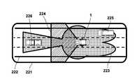
- FIG. 2Bshows a local map according to the present embodiment.
- the local mapis map information configured with information indicating a target such as a vehicle or an obstacle in a certain range centered on the host vehicle, a lane, and the like. Although shown visually in FIG. 2B, it may actually be in a format suitable for information processing, and includes, for example, information indicating the position and range of a target, distance, and information indicating boundaries of roads and lanes.
- the local mapis updated, for example, periodically as the vehicle travels. The interval of the update may be, for example, a period that allows control to ensure safety even in consideration of the relative speed between the host vehicle and the oncoming vehicle.
- an area 221indicates the range of the local map.
- An area 223 indicated by halftone dotsis a detection range of the rider 42 and the radar 43, and a detection range 224 indicated by a lane is a detection range of the camera 41. Note that these detection ranges may not be included in the local map 221.
- various targets, lane divisions, and the like detected by the surrounding area monitoring deviceare shown in a relative positional relationship centering on the host vehicle 1. For example, a front vehicle 226 and a vehicle 225 at the right rear are included in the local map 221 as a target. By continuously updating the local map 221, it is possible to refer in real time to obstacles around the vehicle, road conditions, and the like.
- FIG. 3shows a functional block diagram of the operation control device for automatic driving or driving assistance.
- This operation control deviceis realized, for example, by the ECU 20 shown in FIG. 1 executing the procedure shown in FIG.
- the procedure shown in FIG. 4 and the followingis only a part of the functions related to automatic driving and driving support realized by the driving control apparatus according to the present embodiment.
- the ECU 20automatically controls the traveling of the vehicle 1 toward the destination according to the guide route searched by the ECU 24.
- the ECU 20acquires information on the surrounding condition of the vehicle 1 from the ECUs 22 and 23 and instructs the ECU 21, ECU 26 and 29 based on the acquired information to control steering and acceleration / deceleration of the vehicle 1.
- the procedure shown as a functional blockcorresponds to FIG.
- the external world recognition unit 301indicates, for example, the relative velocity, position and shape, and image of peripheral targets from external environment information indicating peripheral conditions acquired by peripheral monitoring devices such as the camera 41, lidar 42, radar 43, etc.
- Information 303is generated.
- the self position recognition unit 305determines the position of the vehicle on the road, the shape of the vehicle traveling in the periphery, the arrangement centered on the vehicle, and the shape and arrangement of the surrounding structures.
- Local map 307is generated. Note that, in addition to the information 303, in order to create the local map 307, information acquired from other than the surrounding area monitoring apparatus such as map information may be referred to. Further, in this example, in addition to the local map 307, the state of the subject vehicle such as information indicating the sensitivity (detected distance or detection range) of the sensor is also passed to the action candidate determination unit 309 together with the local map.
- the action candidate determination unit 309receives the local map 307 and determines future action candidates.
- the action candidateis information indicating an action that is a candidate for determining the action of the host vehicle.
- the behavior of the vehicleis determined not only by the local map 307 but also by referring to the state of the vehicle etc. in addition to the route information to the destination.
- the state of the host vehicleincludes, for example, a detection distance of a sensor included in the periphery monitoring device. It is desirable to determine an action candidate by autonomous driving with some margin, such as several kilometers before taking action. The reason is that it is not always possible to complete the action by automatic driving, and in such a case, takeover to manual driving may be performed.
- the action candidate determination unit 309preferably does not determine the next action candidate until the action is completed or is canceled.
- a route selection unit 311which will be described later, monitors whether or not a state expected as a result of the selected action has been reached, and notifies the action candidate determination portion 309 of that state.
- the next action candidatemay be determined.
- this configurationis only an example.
- FIG. 4shows an example of the basic action determined as a candidate.
- the action 4Amoves to the left while maintaining the inside of the lane when overtaking the left lane of a large vehicle.
- lateral movementmovement requiring monitoring of the lateral direction and rear of the moving side
- lateral controloperation control for lateral movement
- the lateral directionincludes not only the side (side) but also the front side (referred to as the front side).
- the front sideis, for example, regions 214 and 215 which are detection ranges of the rider 42 in FIG. 2A, and regions 205 and 206 which are detection ranges of the radar 43.
- Lateral movementmay include lane change, in-lane offset, merging, branching, and the like.
- the lateral movementdoes not include traveling along a curve. In order to travel along the road, it is sufficient to monitor only ahead.
- right turn or left turnmay be included in lateral movement. In this case, it is necessary to monitor the side and rear of the bending side.
- the lateral control in the lane like the action 4Ais intended to reduce the feeling of pressure on the driver, etc., and is not always necessary, so there is no need for the above-mentioned allowance for takeover. In this case, there are two candidates for action that can be taken: lateral movement or continuing to travel without doing anything. However, with regard to the behavior 4A, if it is difficult to move sideways, it is sufficient to cancel it, so it is not necessary to prepare as a candidate the behavior of continuing to run without doing anything.
- the action 4B of FIG. 4is an example of the action candidate when there is a preceding vehicle that is later than the host vehicle.
- the first candidateis to follow a leading vehicle.
- the follow-up traveling of a leading vehicleis, for example, a level at which the hands-off (driver's release of the hand from the steering wheel) is permitted in the level of automatic traveling (also referred to as mode).
- the hands-onthe driver holding the steering wheel
- the travel mode at this levelmay be referred to as the second mode.
- the second candidateis to change the lane to the overtaking lane (right side) while maintaining the speed, and overtake the preceding vehicle.
- Action 4Cshows lane change due to a branch.
- the action 4Dindicates a lane change due to merging.
- there is no option to cancel the branchif it is necessary to branch on account of the set route, and in principle the behavior of changing lanes is determined.
- it is not a planned actionwhen it is difficult to change lanes in automatic driving, it is necessary to take over to the driver. Therefore, for example, when traveling in the second mode described above, it is necessary to prepare for takeover and switch to the first mode or a lower automatic operation level before the junction or branch point. is there.
- the automatic driving modeis also selected according to the action.
- actions at intersectionssuch as right turn and left turn may also be determined by the action candidate determination unit 309.
- the route selection unit 311selects one action from among the action candidates as shown in FIG. 4 determined by the action candidate determination unit 309. It is the action to be performed, for which steering, drive, braking are controlled by the vehicle control device. Since there is no choice in the case of one action candidate, only one action candidate is selected. It is possible to determine which of the plurality of candidates is to be selected based on various criteria. In the example of the action 4B, a predetermined threshold is provided for the relative velocity with respect to the leading vehicle, and if the relative velocity with respect to the leading vehicle exceeds the threshold, overtaking is selected, otherwise, the following is selected, etc. Conceivable.
- the route selection unit 311generates route information and speed information 313 in accordance with the selected action.
- the route information and the speed information 313are input to the traveling control unit 315.
- the traveling control unit 315controls steering, driving, and braking based on the input route information and speed information 313. Furthermore, steering, driving, and braking are promptly controlled based on the situation such as a fault around the host vehicle detected by the periphery monitoring device.
- the self position recognition unit 305, the action candidate determination unit 309, and the route selection unit 311can be realized by the ECU 20, the traveling control unit 315 is further realized by performing traveling control by the ECUs 21, 26, 29 and the like. Of course, processing by another ECU may be included if necessary.
- the traveling control unit 315may convert the route or speed into the control amount of the actuator using, for example, a conversion map in which the input route or speed is associated with the control amount of each actuator (including the prime mover). . And travel control is performed using the control amount after conversion.
- FIG. 5shows a part of each process executed by the behavior candidate determination unit 309 and the route selection unit 311. As described above, since these are realized by the ECU 20, the procedure of FIG. 5 is also a process executed by the ECU 20.
- the action candidate determination unit 309creates selectable action candidates based on the local map 307 (S501). Since what is created is data or information indicating an action, this is also referred to as candidate action information. Although details of creation are omitted, candidate information as described with reference to, for example, FIG. 4 is created according to the surrounding environment of the vehicle 1. In addition to the action candidate, the automatic driving mode (level) of the action may be determined together.
- the action candidate determination unit 309determines whether the generated candidate action information includes action information that requires lateral control (S503).
- the lateral controlis control for lateral movement.
- Lateral movementis movement which requires the monitoring of the side and back of the moving side among the movements accompanied by steering to either direction right or left. Lateral movement does not include travel along a curve, but includes right turn and left turn.
- the processproceeds to processing by the route selection unit 311.
- it is determined that the action information requiring the lateral control is includedit is determined whether the sensitivity of the rear sensor and the sensitivity of the sensor of the side, especially the moving direction of the lateral movement are sufficient (S505).
- the rear sensorcorresponds to the lidar 42 whose area 212 in FIG. 2A is the normal detection range
- the radar 43whose area 202, 203 is the normal detection area.
- the sensor of the lateral movement directioncorresponds to the sensor on the movement direction side (right or left) of the lidar 42 in which the areas 211, 213, 214, and 215 are normal detection ranges.
- itcorresponds to a sensor located on the moving direction side (right or left) of the radar 43 in which the areas 201, 204, 205, and 206 are normal detection ranges.
- the sensitivity of each sensorthat is, the detection distance and / or the detection range can be determined, for example, by comparing the detection results by the sensor that sets the overlapping region as the normal detection range, and the output signal of the sensor etc. Can be determined electronically. It is also possible to measure the intensity of a signal for detecting a target whose distance is known. Furthermore, that the sensitivity is sufficient means, for example, that a detection distance which is a detectable distance is equal to or longer than a predetermined distance. Moreover, it may be added on condition that a detection range is more than a predetermined range.
- the sensitivity of the sensoris also referred to as a detection level, and sufficient sensitivity can also be said that the detection level has reached a predetermined level.
- the sensitivity of the rear sensoris sufficient, the detection level of the lidar 42 with the area 212 as the detection range has reached a predetermined level, or the detection level of the radar 43 with the areas 202 and 203 as the detection area Has reached a predetermined level.
- the radar 43since the radar 43 has two sensors as the rear sensors, it may be determined that the sensitivity is sufficient if the detection level has reached a predetermined level for both of them.
- the sensitivitymay be determined to be sufficient if the detection level of the rear sensor on the side of the lateral movement has reached a predetermined level.
- the detection level of the lidar 42 with the area 211, the area 213, the area 214 and the area 215 as the detection rangehas reached a predetermined level, or the area 201 and the area 204
- the detection level of the radar 43 having the detection range of the area 205 and the area 206has reached a predetermined level.
- the sidemay be interpreted in a limited manner as pointing to the direction of the lateral movement, not to both the left and right sides. In this case, if the detection level of the side sensor on the side of the lateral movement direction has reached a predetermined level, it may be determined that the sensitivity is sufficient.
- candidate actions including lateral controlare deleted from the candidate actions (S507).
- candidate actions including lateral control for the lateral movementmay not be deleted.
- candidate behavior information including right movementmay not be deleted even if the sensitivity of the left side sensor is insufficient if the sensitivity of the right side sensor and the rear sensor is sufficient.
- the processproceeds to route selection processing by the route selection unit.
- route selection processingit is determined whether there are a plurality of action candidates, and if there is one, the candidate is selected as the next action, and route / speed information of the action is determined (S517).
- candidate action information of each action candidateis evaluated (S513).
- the candidate action with the highest evaluationis selected as the next action (S515), and the route / speed information of the action is determined (S517).
- the route information and speed information created in this wayare input to the travel control device (or travel control unit), travel is controlled by the route and speed, and the selected action is realized.
- the travel control deviceis configured by a plurality of ECUs, each ECU controls an actuator to be controlled according to the determined route and speed.
- the target of the evaluation in step S513may be various according to the situation as described in FIG.
- the evaluation criterionis the speed difference, and if the relative speed to the vehicle ahead is above a predetermined threshold, it is added to the lane change evaluation point, otherwise it is added to the lane maintenance evaluation point
- the evaluation methodsuch as may be used.
- the action with the higher overall evaluationis selected.
- the actionmay be evaluated focusing on one aspect of the action, and this evaluation may be performed on a number of aspects to make an overall judgment.
- evaluationis made in terms of required time, and if the speed difference is a certain value or more, overtaking is added, and if smaller than a certain value, any required time is not scored. Furthermore, for example, it may be evaluated in terms of fuel consumption, and may be evaluated as adding points to those who can travel at a speed with good fuel consumption. In addition, it is possible to add points to actions that can raise the level of automatic driving, do not add points to actions that are maintained, and deduct points for actions that you lower. Of course, these are only examples and other evaluation methods may be used.
- the action candidate determination unit 309suppresses the lateral control based on the sensitivity of the sensor, but the steps S503 to S507 may be performed by the path selection unit 311.
- the behavior during drivingis determined and realized. And, in this example, when the detection level of at least one of the side and rear sensors does not reach a predetermined level, the lateral control is suppressed. When the detection levels of both the side and rear sensors reach a predetermined level, lateral movement can be selected without suppressing lateral control. In this way, the risk of the vehicle is reduced by performing the lateral control only in the state where not only the lateral side but also the rear side can be detected.
- step S505it is determined whether the sensitivity of both the side sensor and the rear sensor in the designated direction is sufficient. This determination criterion may be the same as step S505.
- the driveris warned about the lane change to the instructed side (S603), and the route information and speed information of the instructed action of the lane change are determined (S605) . After this, traveling control by the traveling control unit is executed.
- the procedure shown in FIG. 7may be executed by the action candidate determination unit 309 together with the action candidate determination in step S501, for example, to determine the mode according to the action.
- This proceduremay be executed by the ECU 20 in the hardware configuration of FIG.
- mode information necessary to determine the modeis collected (S701).
- state information of the host vehicle including the local map and the detection distance of the sensors constituting the periphery monitoring deviceis used as the mode information.
- the mode with the highest automation rateis determined (S703).
- the modeis determined according to each candidate.
- the sensor in frontis a sensor in charge of the detection range in front of the vehicle by the rider 42 and the radar 43 excluding the detection ranges 201 to 204 and 211 to 213 in the detection range shown in FIG. 2A.
- the radar 43 in charge of the area 207is used.
- the front side detection ranges 205, 206, 214, and 215may be side sensors as well as front sensors.
- the camera 41may be included.
- the sensitivity of the sensoris the same as that described in step S505 or the like.
- step S705If it is determined in step S705 that the sensitivity of the front sensor is insufficient, the mode determined in step S703 is changed to a mode lower than the first mode (S713).
- that the sensitivity of the front sensor is sufficientspecifically means that the sensitivity of both the radar 43 in charge of the detection range 207 and the camera 41 is sufficient. It is. Conversely, if the sensitivity of any of the radar 43 and the camera 41 in charge of the detection range 207 is insufficient or fails, it is determined that the sensitivity of the front sensor is insufficient. In this manner, either the first mode or the manual mode is selected according to the type of sensor that can be detected, ie, the sensor with sufficient sensitivity, and the number.
- the way of selectionis not limited to the example described above.
- the combination of sensors determined to be sufficient in sensitivity or the combination of sensors determined to be insufficientmay be predetermined. Conversely, if it is not determined that the sensitivity is sufficient, it can be said that the sensitivity is insufficient (that is, the detection level has not reached the predetermined level).
- the first modeis a mode in which the driver is requested to perform hands-on.
- the mode lower than the first modeincludes, for example, a manual operation mode. If this procedure changes to a mode lower than the first mode, it may also be necessary to change the behavior corresponding to that mode. For example, if the mode after the change is the manual operation mode, all the determined action candidates are cancelled, and the driver is notified of takeover.
- step S705determines whether the sensitivity of the front sensor is sufficient. If it is determined in step S707 that the mode is sufficient, the mode determined in step S703 is maintained without doing anything. If it is determined that the mode is insufficient, it is determined whether the mode determined in step S703 is a mode having a higher automation rate than the first mode (referred to as a mode of higher level than the first mode) (S709). This mode includes a second mode in which the driver may not hold the handle (hands off).
- the mode determined in step S703is changed to the first mode (S711). If the mode determined in step S703 is the first mode, nothing is performed. If it is determined that the mode determined in step S703 is a mode having a lower automation rate than the first mode, the mode is maintained.
- the action itselfmay be left as it is.
- the difference between the first mode and the second modeis the presence or absence of peripheral monitoring by the driver, and it is premised that the driver grips the steering wheel in the first mode even if the action (vehicle control) is the same.
- vehicle control of the systemmatches with the real environment and the driver, it becomes possible to continue the function with the hand attached, and the driver can continue to receive the benefits from the automation.
- the driving operationis temporarily performed differently by the system and the driver, the driver's operation intervention can be immediately performed by holding the steering wheel. Therefore, it is not necessary to delete or change an action, with this point being a difference.
- the operation modeis switched to the corresponding operation mode, and travel control for the selected action is continuously performed. That is, the automatic operation mode determined in the procedure of FIG. 7 is set. As a result, if the sensitivity by the front sensor is insufficient, both the first mode and the second mode are suppressed. If the sensitivity of the front sensor is sufficient, the transition to the first mode is not suppressed even if the sensitivity of either the rear or side sensor is not sufficient.
- the vehicle control devicesuppresses a part of the action by the automatic driving and a part of the automatic driving mode according to the state of the sensor of the periphery monitoring device provided in the vehicle. As a result, the safety of automatic driving can be ensured, and vehicle control can be realized without narrowing the conditions for which automatic driving is possible more than necessary.
- the embodimentsare summarized below.
- a first aspect of the present embodimentis a periphery monitoring means (41, 42, 43) for monitoring the periphery of the host vehicle, And vehicle control means (20-29) for performing traveling control including steering control from the output of the periphery monitoring means,
- the periphery monitoring means of the host vehicleIt is possible to detect targets on the side and rear of the host vehicle, When both the side and rear detection levels reach a predetermined level, the lateral control is not suppressed,
- a vehicle control apparatusis characterized in that lateral control involving the steering control is suppressed when at least one of the side and rear detection levels does not reach a predetermined level.
- the risk of the vehiclecan be reduced by performing the lateral control in a state where not only the lateral side but also the rear side can be detected.
- the lateral controlrefers to suppressing lane change and offset traveling with respect to the center of the white line.
- the lateral controlis Steering control in the driving lane, Lane change, (lane change to destination, overtaking, bifurcation, merging)
- a vehicle control deviceis characterized in that it includes course change (turning to the right or left) at an intersection.
- the lateral controlis a driver lane change according to a request from a driver and a system lane change according to a request from the vehicle control means.
- Including and The detection levels on both the side and the rear of the perimeter monitoring meansare: In the case of the predetermined detection level or higher (good), neither the system lane change nor the driver lane change is suppressed.
- the vehicle control deviceis characterized in that the system lane change is suppressed and the driver lane change is not suppressed if the level is lower (bad) than the predetermined detection level. According to this configuration, since the driver request is performed under the driver monitoring, it is possible to provide currently possible driving support while securing safety.
- the periphery monitoring meansis It can detect targets in front of, behind and on the side of the vehicle.
- the second modeis suppressed without suppressing the first mode when the detection level of at least one of side and rear does not reach a predetermined level
- the vehicle control deviceis characterized in that the first mode and the second mode are suppressed when the front detection level does not reach a predetermined level. This configuration prohibits all when the front can not be detected, and permits only a part when the rear / side can not be seen.
- the fifth aspect of the present embodimentis:
- the sideincludes the left and right sides, and the detection level of any one of the left and right does not reach the predetermined level, and the detection level of the rear reaches the predetermined level.
- a vehicle control deviceis characterized in that the lateral control to the side where the detection level does not reach the predetermined level is suppressed. With this configuration, it is possible to further narrow the conditions for suppressing the lateral control and prevent the room for the automatic operation from being reduced more than necessary.
Landscapes
- Engineering & Computer Science (AREA)
- Automation & Control Theory (AREA)
- Transportation (AREA)
- Mechanical Engineering (AREA)
- Human Computer Interaction (AREA)
- Chemical & Material Sciences (AREA)
- Combustion & Propulsion (AREA)
- Control Of Driving Devices And Active Controlling Of Vehicle (AREA)
- Traffic Control Systems (AREA)
- Steering Control In Accordance With Driving Conditions (AREA)
Abstract
Description
Translated fromJapanese本発明は、例えば自動車の自動運転や運転支援を行うための車両制御装置に関する。The present invention relates to a vehicle control device for performing, for example, automatic driving and driving assistance of a vehicle.
四輪車をはじめとする車両の自動運転または運転支援では、車両の特定の方向または全方向をセンサで監視し、その監視結果に応じて適切な経路や適切な速度での車両の自動運転を制御したり、または運転者による運転を支援したりする。この様な構成で、全てのセンサが正常な場合は、加減速制御及び操舵制御を許可し、前方カメラだけがレーンマーカを正常に認識できない場合は、操舵制御は禁止し、加減速制御は許可し、これ以外の場合は、加減速制御及び操舵制御を禁止する提案がされている(特許文献1参照)。また、自車両が車線変更するために必要な必要検知距離を求め、センサの検知可能限界距離が必要検知距離より小さい場合、車線変更できないことをドライバーに通知することが提案されている(特許文献2等参照)。In automatic driving or driving assistance for vehicles including four-wheeled vehicles, sensors monitor specific directions or all directions of the vehicle with sensors, and according to the monitoring results, automatic driving of the vehicle at an appropriate route or speed. Control or assist the driver in driving. With this configuration, when all sensors are normal, acceleration / deceleration control and steering control are permitted. When only the front camera can not recognize the lane marker normally, steering control is prohibited and acceleration / deceleration control is permitted. In other cases, proposals have been made to prohibit acceleration / deceleration control and steering control (see Patent Document 1). In addition, it has been proposed to obtain the necessary detection distance required for the host vehicle to change lanes, and notify the driver that lane change can not be made if the detectable limit distance of the sensor is smaller than the required detection distance (Patent Document 2nd grade).
しかしながら、上記従来例では運転制御の制限が過大であり、安全な運転制御または運転支援を実現しつつ、運転制御または運転支援の自動化率をより高めることが求められている。However, in the above-described conventional example, the restriction of the operation control is excessive, and it is required to further increase the automation ratio of the operation control or the operation support while realizing the safe operation control or the operation support.
本発明は上記従来例に鑑みて成されたもので、安全な運転制御または運転支援を実現しつつ、運転制御または運転支援の自動化率をより高めることができる車両制御装置を提供することを目的とする。The present invention has been made in view of the above-described conventional example, and it is an object of the present invention to provide a vehicle control device capable of further increasing the automation ratio of drive control or drive support while realizing safe drive control or drive support. I assume.
上記目的を達成するために本発明は以下の構成を有する。In order to achieve the above object, the present invention has the following configuration.
すなわち、本発明の一側面によれば、自車両の周辺監視を行う周辺監視手段(41,42,43)と、
前記周辺監視手段の出力から、操舵制御を含む走行制御を行う車両制御手段(20-29)とを有し、
自車両の前記周辺監視手段は、
自車両の側方及び後方の物標を検知可能であり、
前記側方及び後方の両方の検知レベルが所定レベルに達している場合に、前記横制御を抑制せず、
前記側方及び後方の少なくとも一方の検知レベルが所定レベルに達しない場合に、前記操舵制御を伴う横制御を抑制することを特徴とする車両制御装置が提供される。That is, according to one aspect of the present invention, perimeter monitoring means (41, 42, 43) for performing perimeter monitoring of the host vehicle;
And vehicle control means (20-29) for performing traveling control including steering control from the output of the periphery monitoring means,
The periphery monitoring means of the host vehicle
It is possible to detect targets on the side and rear of the host vehicle,
When both the side and rear detection levels reach a predetermined level, the lateral control is not suppressed,
There is provided a vehicle control apparatus characterized in that lateral control accompanied by the steering control is suppressed when at least one of the side and rear detection levels does not reach a predetermined level.
本発明によれば、安全な運転制御または運転支援を実現しつつ、運転制御または運転支援の自動化率をより高めることができる。According to the present invention, it is possible to further enhance the automation rate of operation control or operation support while realizing safe operation control or operation support.
本発明のその他の特徴及び利点は、添付図面を参照とした以下の説明により明らかになるであろう。なお、添付図面においては、同じ若しくは同様の構成には、同じ参照番号を付す。Other features and advantages of the present invention will become apparent from the following description taken in conjunction with the accompanying drawings. In the attached drawings, the same or similar configurations are denoted by the same reference numerals.
添付図面は明細書に含まれ、その一部を構成し、本発明の実施の形態を示し、その記述と共に本発明の原理を説明するために用いられる。
<第一実施形態>
●自動運転および走行支援の概要
次に自動運転についてその一例の概略を説明する。自動運転では、ドライバーは走行前に、車両に搭載されたナビゲーションシステムから目的地を設定し、サーバやナビゲーションシステムによって目的地までの経路を決定しておく。車両が発進されると、車両の有するECUなどで構成される車両制御装置(或いは運転制御装置)は、その経路に沿って車両を目的地まで運転する。その間に、経路や道路状況などの外部環境、ドライバーの状態などに応じて適時に適切な行動を決定し、その行動のためにたとえば駆動制御、操舵制御、制動制御などを行って車両を走行させる。これらの制御をまとめて走行制御とよぶこともある。First Embodiment
Outline of Automatic Driving and Driving Support Next, an outline of an example of automatic driving will be described. In automatic driving, a driver sets a destination from a navigation system mounted on a vehicle before traveling, and determines a route to the destination by a server or a navigation system. When the vehicle is started, a vehicle control device (or a drive control device) configured by an ECU or the like of the vehicle drives the vehicle to a destination along the route. In the meantime, appropriate actions are determined in a timely manner according to the external environment such as the route and the road condition, the driver's condition, etc., and drive control, steering control, braking control, etc. are performed to drive the vehicle. . These controls may be collectively referred to as travel control.
自動運転には、自動化率(もしくはドライバーに要求するタスクの量)によっていくつかのレベル(あるいはモードとも呼ぶ)がある。たとえば最上位のレベルでは、ドライバーは運転以外のことに注意を向けていてもよい。これはたとえば高速道路上の渋滞で前走車に追従する場合など、制御が比較的容易な場合に行われる。また、その下位レベルでは、ドライバーはハンドルを持たずともよいが、周囲の状況などに注意を払う必要がある。このレベルはたとえば、高速道路上で車線を維持しつつ走行する場合などに適用してよい。このレベルを本例では第2のモードと呼ぶこともある。なお運転者が周囲に注意していることはドライバー状態検知カメラ41aにより、ハンドルを持っていることはハンドル把持センサにより検知できる。さらにその下位レベルでは、ドライバーはハンドル操作やスロットル操作を行わなくともよいが、ドライバーへのテイクオーバに備えてハンドルを持ち、運転に注意を払う必要がある。このレベルは、たとえば高速道路上の分岐や合流に適用してよい。このレベルを本例では第1のモードと呼ぶこともある。さらにその下位レベルでは、より自動化率は低下する。最低レベルは手動運転であるが、部分的に自動化した運転支援を含むこともあり、本例では自動運転の一レベルとしている。There are several levels (also referred to as modes) in the automated driving depending on the automation rate (or the amount of tasks required of the driver). For example, at the top level, the driver may be alerting other than driving. This is done when the control is relatively easy, for example when following a leading vehicle in a traffic jam on a freeway. Also, at the lower level, the driver does not have to have a handle, but needs to pay attention to the surrounding conditions and the like. This level may be applied, for example, when traveling while maintaining a lane on a freeway. This level may be referred to as a second mode in this example. The driver's attention to the surroundings can be detected by the driver
上述した運転支援とは、運転の主体となるドライバーによる運転操作を、周辺の監視や部分的な自動化により支援する機能である。たとえば前方のみを監視して障害を検知したなら制動をかける自動ブレーキ機能や、斜め後方の車両を検知してドライバーに注意を促す後方監視機能、駐車スペースへの駐車機能などがある。The above-described driving support is a function that supports driving operation by a driver who is the main body of driving by monitoring the surrounding area or partial automation. For example, there is an automatic braking function that applies braking only if the front is monitored and detects a fault, a rear monitoring function that detects the vehicle behind diagonally and warns the driver, and a parking function to the parking space.
なお、自動運転中であってもドライバーによる介入があってもよい。たとえば、自動運転中にドライバーが操舵や制動をかけると、自動運転レベルを運転支援のレベルまで下げ、ドライバーによる運転操作を優先させてよい。その場合には、ドライバーが操作を止めた後、自車両状態および外部環境に応じた自動運転レベルを再設定して自動運転を続行してよい。例えば本実施形態における操舵操作の例として、上述した第1のモード以上の自動化率の自動運転で高速道路を走行中におけるウインカーレバー操作がある。たとえばこのような状態でドライバーがウインカー操作をすると、車両は車線変更の指示があったとして指示された側の車線へと車線変更する。この場合、操舵や制動、駆動などの制御は、ECU等で構成する走行制御部が、車両の周囲の障害物等を監視しつつ行う。In addition, even during automatic driving, there may be an intervention by the driver. For example, when the driver steers or brakes during automatic driving, the automatic driving level may be lowered to the level of the driving support to give priority to the driving operation by the driver. In that case, after the driver stops the operation, the automatic driving level may be reset according to the vehicle state and the external environment to continue the automatic driving. For example, as an example of the steering operation in the present embodiment, there is a winker lever operation during traveling on a high speed road by automatic driving at an automation rate of the first mode or more described above. For example, when the driver performs a turn signal operation in such a state, the vehicle changes lanes to the lane indicated as having been instructed to change lanes. In this case, the traveling control unit configured by an ECU or the like performs control such as steering, braking, or driving while monitoring an obstacle or the like around the vehicle.
自動運転レベル(あるいはモード)が切り替えられる場合には、そのことは車両からドライバーへと音声や表示、振動などによって通知される。例えば自動運転が上述した第1のモードから第2のモードへと切り替えられる場合には、ドライバーに対してハンドルを離してもよい旨が通知される。逆の場合には、ドライバーに対してハンドルを把持するよう通知される。この通知はハンドル把持センサによりドライバーがハンドルを把持したことが検知されるまで繰り返し出される。そしてたとえば制限時間内あるいはモード切り替えの限界点までにハンドルが把持されなければ、安全な場所に停車させるなどの操作が行われてよい。自動運転は概ね上述したように行われ、そのための構成及び制御について以下で説明する。When the automatic driving level (or mode) is switched, that is notified from the vehicle to the driver by voice, display, vibration or the like. For example, when the automatic driving is switched from the first mode to the second mode described above, the driver is notified that the steering wheel may be released. In the opposite case, the driver is notified to hold the handle. This notification is repeatedly issued until the handle grip sensor detects that the driver grips the handle. Then, for example, if the steering wheel is not gripped within the time limit or the limit point of mode switching, an operation such as stopping at a safe place may be performed. Automated operation is generally performed as described above, and the configuration and control therefor are described below.
●車両制御装置の構成
図1は、本発明の一実施形態に係る車両用制御装置のブロック図であり、車両1を制御する。図1において、車両1はその概略が平面図と側面図とで示されている。車両1は一例としてセダンタイプの四輪の乗用車である。Configuration of Vehicle Control Device FIG. 1 is a block diagram of a control device for a vehicle according to an embodiment of the present invention, which controls a vehicle 1. In FIG. 1, the vehicle 1 is schematically shown in a plan view and a side view. The vehicle 1 is a sedan-type four-wheeled passenger car as an example.
図1の制御装置は、制御ユニット2を含む。制御ユニット2は車内ネットワークにより通信可能に接続された複数のECU20~29を含む。各ECUは、CPUに代表されるプロセッサ、半導体メモリ等の記憶デバイス、外部デバイスとのインタフェース等を含む。記憶デバイスにはプロセッサが実行するプログラムやプロセッサが処理に使用するデータ等が格納される。各ECUはプロセッサ、記憶デバイスおよびインタフェース等を複数備えていてもよい。The control device of FIG. 1 includes a
以下、各ECU20~29が担当する機能等について説明する。なお、ECUの数や、担当する機能については、車両1の適宜設計可能であり、本実施形態よりも細分化したり、あるいは、統合することが可能である。The functions and the like that each of the
ECU20は、車両1の自動運転に関わる制御を実行する。自動運転においては、車両1の操舵と、加減速の少なくともいずれか一方を自動制御する。後述する制御例では、操舵と加減速の双方を自動制御する。The
ECU21は、電動パワーステアリング装置3を制御する。電動パワーステアリング装置3は、ステアリングホイール31に対する運転者の運転操作(操舵操作)に応じて前輪を操舵する機構を含む。また、電動パワーステアリング装置3は操舵操作をアシストしたり、あるいは、前輪を自動操舵するための駆動力を発揮するモータや、操舵角を検知するセンサ等を含む。車両1の運転状態が自動運転の場合、ECU21は、ECU20からの指示に対応して電動パワーステアリング装置3を自動制御し、車両1の進行方向を制御する。The
ECU22および23は、車両の周囲状況を検知する検知ユニット41~43の制御および検知結果の情報処理を行う。検知ユニット41は、車両1の前方を撮影するカメラであり(以下、カメラ41と表記する場合がある。)、本実施形態の場合、車両1のルーフ前部に2つ設けられている。カメラ41が撮影した画像の解析により、物標の輪郭抽出や、道路上の車線の区画線(白線等)を抽出可能である。検知ユニット41aは、ドライバーの状態を検知するためのカメラであり(以下、ドライバー状態検知カメラ41aと表記する場合がある。)、ドライバーの表情をとらえられるように設置されており、不図示ではあるが、その画像データの処理を行うECUに接続されている。またドライバー状態を検知するためのセンサとして、不図示のハンドル把持センサがある。これによりドライバーがハンドルを握っているか否かを検知できる。The
検知ユニット42は、ライダ(Light Detection and Ranging、或いはLaser Imaging Detection and Ranging)であり(以下、ライダ42と表記する場合がある)、車両1の周囲の物標を検知したり、物標との距離を測距する。本実施形態の場合、ライダ42は5つ設けられており、車両1の前部の各隅部に1つずつ、後部中央に1つ、後部各側方に1つずつ設けられている。検知ユニット43は、ミリ波レーダであり(以下、レーダ43と表記する場合がある)、車両1の周囲の物標を検知したり、物標との距離を測距する。本実施形態の場合、レーダ43は5つ設けられており、車両1の前部中央に1つ、前部各隅部に1つずつ、後部各隅部に一つずつ設けられている。The
ECU22は、一方のカメラ41と、各ライダ42の制御および検知結果の情報処理を行う。ECU23は、他方のカメラ42と、各レーダ43の制御および検知結果の情報処理を行う。車両の周囲状況を検知する装置を二組備えたことで、検知結果の信頼性を向上でき、また、カメラ、ライダ、レーダといった種類の異なる検知ユニットを備えたことで、車両の周辺環境の解析を多面的に行うことができる。The
ECU24は、ジャイロセンサ5、GPSセンサ24b、通信装置24cの制御および検知結果あるいは通信結果の情報処理を行う。ジャイロセンサ5は車両1の回転運動を検知する。ジャイロセンサ5の検知結果や、車輪速等により車両1の進路を判定することができる。GPSセンサ24bは、車両1の現在位置を検知する。通信装置24cは、地図情報や交通情報を提供するサーバと無線通信を行い、これらの情報を取得する。ECU24は、記憶デバイスに構築された地図情報のデータベース24aにアクセス可能であり、ECU24は現在地から目的地へのルート探索等を行う。The
ECU25は、車車間通信用の通信装置25aを備える。通信装置25aは、周辺の他車両と無線通信を行い、車両間での情報交換を行う。The
ECU26は、パワープラント6を制御する。パワープラント6は車両1の駆動輪を回転させる駆動力を出力する機構であり、例えば、エンジンと変速機とを含む。ECU26は、例えば、アクセルペダル7Aに設けた操作検知センサ7aにより検知した運転者の運転操作(アクセル操作あるいは加速操作)に対応してエンジンの出力を制御したり、車速センサ7cが検知した車速等の情報に基づいて変速機の変速段を切り替える。車両1の運転状態が自動運転の場合、ECU26は、ECU20からの指示に対応してパワープラント6を自動制御し、車両1の加減速を制御する。The
ECU27は、方向指示器8を含む灯火器(ヘッドライト、テールライト等)を制御する。図1の例の場合、方向指示器8は車両1の前部、ドアミラーおよび後部に設けられている。The
ECU28は、入出力装置9の制御を行う。入出力装置9は運転者に対する情報の出力と、運転者からの情報の入力の受け付けを行う。音声出力装置91は運転者に対して音声により情報を報知する。表示装置92は運転者に対して画像の表示により情報を報知する。表示装置92は例えば運転席表面に配置され、インストルメントパネル等を構成する。なお、ここでは、音声と表示を例示したが振動や光により情報を報知してもよい。また、音声、表示、振動または光のうちの複数を組み合わせて情報を報知してもよい。更に、報知すべき情報のレベル(例えば緊急度)に応じて、組み合わせを異ならせたり、報知態様を異ならせてもよい。入力装置93は運転者が操作可能な位置に配置され、車両1に対する指示を行うスイッチ群であるが、音声入力装置も含まれてもよい。The
ECU29は、ブレーキ装置10やパーキングブレーキ(不図示)を制御する。ブレーキ装置10は例えばディスクブレーキ装置であり、車両1の各車輪に設けられ、車輪の回転に抵抗を加えることで車両1を減速あるいは停止させる。ECU29は、例えば、ブレーキペダル7Bに設けた操作検知センサ7bにより検知した運転者の運転操作(ブレーキ操作)に対応してブレーキ装置10の作動を制御する。車両1の運転状態が自動運転の場合、ECU29は、ECU20からの指示に対応してブレーキ装置10を自動制御し、車両1の減速および停止を制御する。ブレーキ装置10やパーキングブレーキは車両1の停止状態を維持するために作動することもできる。また、パワープラント6の変速機がパーキングロック機構を備える場合、これを車両1の停止状態を維持するために作動することもできる。The
●周辺監視装置
図1に示したカメラ41、ライダ42、レーダ43は、車両周囲の物標などを検知する周辺監視装置を構成している。図2Aはその周辺監視装置により検知される範囲の例を示す。図2Aにおいて、網点で示す領域201、202,203,204,205,206,207などは、レーダ43による検知範囲を示す。特に領域201は車両1の右側方、領域204は左側方、領域202は右後方、領域203は左後方の領域である。また、領域205は左前側方、領域206は右前側方の領域である。対応するレーダ43は、それぞれの領域にある障害物や車両などの物標を検知し、その距離を測定する。そしてこのライダ42により、たとえば右後方を走行する車両や、右車線を追い抜いて行く車両などを検知できる。点線で囲った領域211、212、213,214,215などは、ライダ42による検知範囲を示す。特に領域211は車両1の右側方、領域213は車両1の左側方、領域212は後方の領域である。領域214は車両1の左前側方、領域215は右前側方の領域である。対応するレーダ43は、それぞれの領域にある障害物や車両などの物標を検知し、その距離を測定する。そしてこのレーダ43により、たとえば右後方を走行する車両や、右車線を追い抜いて行く車両などを検知できる。斜線で示す領域219はカメラ41による検知範囲を示す。本例ではカメラ41は2台備えられているが、ほぼ重複した領域を検知範囲とするため、一つのみを示した。カメラ41で撮影された画像は画像認識され、たとえば走行車線を示す白線等の基準が画像から特定され、車線維持や車線変更のために参照される。Peripheral Monitoring Device The
このように、異なるセンサによる検知範囲は重複しているため、センサの冗長化が実現されている。これによって信頼性が一層高まるとともに、同一の領域を検知範囲とする異なるセンサによる検知結果を比較することで、検知レベルを特定できる。検知レベルには、たとえば検知できる距離や、検知できる範囲などが含まれる。たとえばライダ42及びレーダ43の二種類のセンサで同一の領域を検知していながら、一方のセンサでは検知され、他方のセンサでは検知されていない物標があるとする。この場合、後者のセンサは前者のセンサと比較して、その検知距離が短いか、あるいは検知範囲が狭いと推定できる。あるいは、たとえばライダ42またはレーダ43のいずれか一種類のセンサのみによりガードレースのような連続する物標を対象として検知し、検知可能な距離によって検知距離を推定することもできる。またあるいは、不図示の自己診断回路によりセンサの出力信号などを監視し、そこからセンサ自体の不具合を知ることもできる。この場合には、センサの検知距離や検知範囲はないものとみなしてもよい。このようにしてセンサすなわち周辺監視装置の検知レベルを知る、または推定することができる。As described above, since detection ranges of different sensors overlap, redundancy of sensors is realized. This further enhances the reliability, and the detection level can be specified by comparing detection results of different sensors whose detection range is the same area. The detection level includes, for example, a detectable distance and a detectable range. For example, it is assumed that there are targets detected by one sensor and not detected by the other sensor while the same region is detected by the two types of sensors of the
●ローカルマップ
図2Bに本実施形態に係るローカルマップを示す。ローカルマップとは、自車両を中心とした一定の範囲の車両や障害物などの物標や車線などを示す情報で構成した地図情報である。図2Bには視覚的に示したが、実際には情報処理に適した形式でよく、たとえば物標の位置や範囲、距離を示す情報、道路や車線の境界を示す情報などが含まれる。ローカルマップは、車両の走行に応じてたとえば定期的に更新される。更新の間隔は、たとえば自車両と対向車両との相対速度などを考慮しても、安全を確保した制御が実現できる程度の期間であればよい。図2Bにおいて、領域221がローカルマップの範囲を示す。なお、網点で示した領域223はライダ42及びレーダ43の検知範囲であり、車線で示した検知範囲224はカメラ41の検知範囲である。なおこれらの検知範囲はローカルマップ221には含まれていなくともよい。ローカルマップ221には、周辺監視装置によって検知された種々の物標や車線区分などが、自車両1を中心とした相対的な位置関係で示されている。例えば物標として前走車226や右後方の車両225がローカルマップ221に含まれる。このローカルマップ221を更新し続けることで、自車両の周囲の障害物や道路状況等を実時間で参照することができる。Local Map FIG. 2B shows a local map according to the present embodiment. The local map is map information configured with information indicating a target such as a vehicle or an obstacle in a certain range centered on the host vehicle, a lane, and the like. Although shown visually in FIG. 2B, it may actually be in a format suitable for information processing, and includes, for example, information indicating the position and range of a target, distance, and information indicating boundaries of roads and lanes. The local map is updated, for example, periodically as the vehicle travels. The interval of the update may be, for example, a period that allows control to ensure safety even in consideration of the relative speed between the host vehicle and the oncoming vehicle. In FIG. 2B, an
●運転制御装置
図3に自動運転あるいは運転支援のための運転制御装置の機能的なブロック図を示す。この運転制御装置は、たとえば図1に示したECU20が、図4以下に示す手順を実行することで実現される。もちろん図4以下に示した手順は、運転制御装置が実現する自動運転や運転支援に係る機能のうち、本実施形態に係るごく一部に過ぎない。たとえばECU20は、運転者により目的地と自動運転が指示されると、ECU24により探索された案内ルートにしたがって、目的地へ向けて車両1の走行を自動制御する。自動制御の際、ECU20はECU22および23から車両1の周囲状況に関する情報を取得し、取得した情報に基づきECU21、ECU26および29に指示して、車両1の操舵、加減速を制御する。この手順を機能ブロックとして示したものが図3に相当する。Operation Control Device FIG. 3 shows a functional block diagram of the operation control device for automatic driving or driving assistance. This operation control device is realized, for example, by the
外界認識部301は、カメラ41、ライダ42、レーダ43等の周辺監視装置で取得した周辺の状況を示す外部環境情報から、たとえば周辺の物標の相対速度、位置及び形状、および画像などを示す情報303を生成する。そして情報303に基づいて、自己位置認識部305が、道路上における自車両の位置、周辺を走行する車両の形状及び自車両を中心とした配置、また周辺の構造物の形状及び配置を決定し、ローカルマップ307を生成する。なおローカルマップ307の作成のためには、情報303に加えて、地図情報など、周辺監視装置以外から取得した情報を参照してもよい。また、本例では、ローカルマップ307に加えて、センサの感度(検知距離や検知範囲)を示す情報など自車両の状態もローカルマップと併せて行動候補決定部309に渡される。The external
行動候補決定部309は、ローカルマップ307を入力として、今後の行動候補を決定する。行動候補は、自車両の行動を決定するにあたり、その候補となる行動を示す情報である。自車両の行動は、ローカルマップ307のみならず、目的地までのルート情報に加えて、自車両の状態などを参照して決定される。自車両の状態には、たとえば周辺監視装置に含まれたセンサの検知距離などがある。自動運転による行動候補は、その行動を起こす例えば数キロ手前など、余裕をもって決定することが望ましい。それというのも、必ずしも自動運転でその行動を完了できるとは限らず、そのような場合には、手動運転へのテイクオーバを行うことがあるためである。たとえば、出口や分岐、給油等のために走行中の車線から隣の車線へと移動しなければならないこともある。そのような場合には、隣の車線に進入するスペースを見つけられなければ、車線変更しなければならない地点までに手動運転へとテイクオーバする。なお、行動候補決定部309は、或る行動をとることがすでに決定されている場合には、その行動が完了するか、あるいは取りやめになるまでは、次の行動候補を決定しないことが望ましい。そのためにはたとえば、後述する経路選択部311が、選択した行動の結果として期待される状態に至ったか否かを監視し、当該状態に至ったならそのことを行動候補決定部309に通知して次の行動候補を決定させるよう構成してよい。もちろんこの構成は一例に過ぎない。The action
図4に候補として決定される原則的な行動の一例を示す。行動4Aは、大型車両の左車線を追い抜く場合に、車線内を維持したまま、左側に移動する。このように左右何れかの方向への操舵を伴う移動のうち、移動する側の横方向および後方の監視を必要とする移動を横移動と呼び、横移動のための運転制御を横制御と呼ぶ。ここで、横方向には真横(側方)のみならず、前方の側方(前側方と呼ぶ)も含む。前側方とは、例えば図2Aにおいてライダ42の検知範囲である領域214,215、レーダ43の検知範囲である領域205,206などである。横移動には、車線変更や車線内のオフセット、合流、分岐などを含めてよい。なお本例では、横移動には、カーブに沿った走行は含まれない。道なりに走行するためには前方の監視だけで足りるためである。また、右折や左折などは横移動にさらに含めてよい。この場合には、曲がる側の横方向および後方の監視が必要となるためである。さて、行動4Aのような車線内での横制御はドライバーへの圧迫感の軽減などを目的としており、必ずしも必要ではないので、上述したようなテイクオーバのための余裕はなくともよい。この場合には、取り得る行動の候補は、横移動か、或いは何もせずに走行を続けるという2つになる。ただし、行動4Aについては、横移動が難しい状況であればそれを取りやめれば足りるので、何もせずに走行を続けるという行動については候補として用意しなくともよい。FIG. 4 shows an example of the basic action determined as a candidate. The
図4の行動4Bは、自車両より遅い前走車がいる場合の行動候補の例である。この場合には、2つの選択肢がある。第一の候補は、前走車への追従走行を行う、というものである。前走車の追従走行は、自動走行のレベル(あるいはモードとも呼ぶ。)でいえば、たとえばハンズオフ(運転者がハンドルから手を離すこと)を許容するレベルである。本例では、ハンズオン(運転者がハンドルを持つこと)を第1のモードと呼ぶのに対して、このレベルの走行モードを第2のモードと呼ぶこともある。また第二の候補は、速度を維持したまま追い越し車線(右側)へと車線変更し、前走車を追い越すというものである。The
行動4Cは分岐による車線変更を示す。また行動4Dは合流による車線変更を示す。これらの場合、設定されたルートの都合上分岐しなければならないなら分岐を取りやめるという選択肢は原則としてなく、車線変更という行動が決定される。ただし危険回避などのためには車線変更を取りやめることもあり得るが、計画される行動ではない。したがって、自動運転で車線変更が困難な場合にはドライバーへのテイクオーバをしなければならない。そのために、例えば上述した第2のモードで走行していた場合には、テイクオーバに備えて、合流点または分岐点の手前で第1のモードあるいはそれ以下の自動運転レベルへと切り替えておく必要がある。このように行動に合わせて自動運転モードも選択される。このほか、右折や左折など、交差点における行動も、行動候補決定部309において決定されてよい。
さて図3に戻ると、経路選択部311は、行動候補決定部309により決定された、図4に示したような行動候補のうちから、一つの行動を選択する。それが実行される行動となり、そのために操舵、駆動、制動が、車両制御装置によって制御される。行動候補が一つの場合には選択の余地はないので、ただ一つの行動候補が選択される。複数の候補のうちからいずれの候補を選択するかは、様々な基準で決定し得る。行動4Bの例では、前走車に対する相対速度に所定の閾値を設けておき、前走車に対する相対速度が閾値を超えているなら追い越しを選択し、そうでなければ追従を選択することなどが考えられる。また、目的地までのルートの都合上、例えば前方に分岐があって、それまでに(たとえば所定時間内あるいは所定距離内に)車線変更しなければならない場合には、前倒しで車線変更するよう判断することなどもあり得る。いずれにしてもこれらは選択基準の一例であって、他の基準を適用してもよい。また経路選択部311は、選択した行動に即した経路情報および速度情報313を生成する。経路情報および速度情報313は走行制御部315に入力される。Referring back to FIG. 3, the
走行制御部315は、入力された経路情報および速度情報313に基づいて、操舵、駆動、制動を制御する。さらに、周辺監視装置により検知された自車両周囲の障害などの状況にも基づいて、即応的に操舵、駆動、制動を制御する。なお自己位置認識部305、行動候補決定部309、経路選択部311はECU20により実現できたが、走行制御部315はさらに、ECU21,26,29などにより走行制御することで実現される。もちろん必要があれば他のECUによる処理を含めてもよい。走行制御部315は、たとえば入力される経路や速度と各アクチュエータ(原動機などを含む)の制御量とを対応付けた変換マップなどを用いて、経路や速度をアクチュエータの制御量に変換してよい。そして、変換後の制御量を用いて走行制御を行う。The traveling
●行動候補決定および経路選択処理
図5に、行動候補決定部309および経路選択部311により実行されるそれぞれの処理の一部を示す。前述したようにこれらはECU20により実現されることから、図5の手順はECU20により実行される処理でもある。行動候補決定部309は、ローカルマップ307に基づいて、選択可能な行動候補を作成する(S501)。作成されるのは行動を示すデータ或いは情報であることから、これを候補行動情報とも呼ぶ。作成の詳細は省くが、例えば図4を参照して説明したような候補情報が車両1の周辺環境に応じて作成される。また、行動候補と共に、その行動の自動運転モード(レベル)を併せて決定してもよい。次に行動候補決定部309は、作成した候補行動情報に、横制御が必要な行動情報が含まれるか判定する(S503)。本実施形態では、横制御とは、前述したが、横移動のための制御である。横移動とは、左右何れかの方向への操舵を伴う移動のうち、移動する側の横方向および後方の監視を必要とする移動のことである。横移動にはカーブに沿った走行は含まれず、右折や左折は含まれる。作成した候補行動情報に、横制御が必要な行動情報が含まれないと判定した場合には、経路選択部311による処理へと移行する。一方横制御が必要な行動情報が含まれると判定した場合には、後方のセンサの感度および、側方特に横移動の移動方向のセンサの感度が十分か判定する(S505)。Behavior Candidate Determination and Route Selection Process FIG. 5 shows a part of each process executed by the behavior
ここで、後方のセンサとは、図2Aの領域212を通常の検知範囲とするライダ42と、領域202,203を通常の検知範囲とするレーダ43に対応する。また、側方の移動方向のセンサとは、領域211、213、214、215を通常の検知範囲とするライダ42のうち、移動方向側(右または左)に有るセンサに対応する。同様に、領域201,204、205、206を通常の検知範囲とするレーダ43のうち、移動方向側(右または左)に有るセンサに対応する。各センサの感度すなわち検知距離および/または検知範囲は、たとえば重複する領域を通常の検知範囲とするセンサによる検知結果を比較することで判定でき、また不図示の自己診断回路によってセンサの出力信号等から電子的に判断できる。また距離が分かっている物標を対象としてそれを検知する信号の強さなどによって測定することもできる。さらに感度が十分であるとは、たとえば検知可能な距離である検知距離が所定距離以上であることなどである。また検知範囲が所定の範囲以上で有ることを条件として加えてもよい。センサの感度を検知レベルとも呼び、感度が十分であるとは、検知レベルが所定レベルに達していることということもできる。Here, the rear sensor corresponds to the
すなわち、後方のセンサの感度が十分であるとは、領域212を検知範囲とするライダ42の検知レベルが所定レベルに達しているか、領域202と領域203とを検知範囲とするレーダ43の検知レベルが所定レベルに達していることである。ただし、レーダ43は、後方センサとして2つのセンサを有しているので、この両方についてともに検知レベルが所定レベルに達していれば感度が十分と判定してよい。あるいは、横移動の方向側の後方センサの検知レベルが所定レベルに達していれば感度が十分と判定してもよい。同様に側方のセンサの感度が十分であるとは、領域211と領域213と領域214と領域215とを検知範囲とするライダ42の検知レベルが所定レベルに達しているか、領域201と領域204と領域205と領域206とを検知範囲とするレーダ43の検知レベルが所定レベルに達していることである。ただし、側方とは左右両方の側方ではなく、横移動の方向を指すものと限定的に解釈してもよい。この場合には、横移動の方向側の側方センサの検知レベルが所定レベルに達していれば感度が十分と判定してもよい。That is, if the sensitivity of the rear sensor is sufficient, the detection level of the
さて、後方および移動方向のセンサ感度が十分ではないと判定された場合には、候補行動から、横制御を含む候補行動を削除する(S507)。ただし、横移動の方向の側方センサおよび後方センサの感度が十分であれば、その横移動のための横制御を含む候補行動は削除しなくともよい。例えば右移動を含む候補行動情報は、右の側方センサと後方センサの感度が十分ならば、左の側方センサの感度が不十分であっても削除しなくてよい。If it is determined that the sensor sensitivity in the backward direction and the moving direction is not sufficient, candidate actions including lateral control are deleted from the candidate actions (S507). However, if the sensitivity of the side sensor and the rear sensor in the direction of lateral movement is sufficient, candidate actions including lateral control for the lateral movement may not be deleted. For example, candidate behavior information including right movement may not be deleted even if the sensitivity of the left side sensor is insufficient if the sensitivity of the right side sensor and the rear sensor is sufficient.
このようにして行動候補を生成すると、次に経路選択部による経路選択処理に移る。まず行動候補が複数あるか判定し、一つであればその候補を次の行動として選択し、その行動の経路・速度情報を決定する(S517)。一方、複数の候補がある場合には、そのうちのひとつを選択する。そのために各行動候補の候補行動情報を評価する(S513)。そして最高評価の候補行動を次の行動として選択し(S515)、その行動の経路・速度情報を決定する(S517)。このようにして作成された経路情報および速度情報は、走行制御装置(あるいは走行制御部)に入力され、その経路と速度で走行が制御されて選択された行動が実現される。走行制御装置が複数のECUで構成される場合には、それぞれのECUがそれぞれの制御対象のアクチュエータを、決定された経路と速度とに従って制御する。After the action candidate is generated in this manner, the process proceeds to route selection processing by the route selection unit. First, it is determined whether there are a plurality of action candidates, and if there is one, the candidate is selected as the next action, and route / speed information of the action is determined (S517). On the other hand, when there are a plurality of candidates, one of them is selected. Therefore, candidate action information of each action candidate is evaluated (S513). Then, the candidate action with the highest evaluation is selected as the next action (S515), and the route / speed information of the action is determined (S517). The route information and speed information created in this way are input to the travel control device (or travel control unit), travel is controlled by the route and speed, and the selected action is realized. When the travel control device is configured by a plurality of ECUs, each ECU controls an actuator to be controlled according to the determined route and speed.
ここで、ステップS513における評価の対象は、図4で説明したように、状況に応じて様々であってよい。例えば行動4Bの車線変更の例では、評価基準は速度差であり、前走車に対する相対速度が所定の閾値以上なら車線変更の評価点に加点し、そうでないなら車線維持の評価点に加点する、といった評価の仕方を用いてよい。このほかに評価対象があればそれも評価し、総合評価が高い方の行動が選択される。あるいは、行動の一つの面に着目してその行動を評価し、この評価をいくつもの面について行って総合的に判断してもよい。たとえば前述の例では、所用時間の面から評価し、速度差が一定以上なら追い越しに加点し、一定より小さいなら所要時間についてはいずれの行動についても加点しない。さらに例えば燃費の面から評価して、燃費の良い速度で走行できる方に加点する、というように評価してもよい。また自動運転レベルを上げられる行動に加点し、維持する行動に加点せず、下げる行動については減点する、などとしてもよい。もちろんこれらは一例であって、他の評価方法であってもよい。なお図5では、センサの感度による横制御の抑制を行動候補決定部309で行っているが、ステップS503~S507を経路選択部311で行ってもよい。Here, the target of the evaluation in step S513 may be various according to the situation as described in FIG. For example, in the example of lane change in
以上のようにして、走行中の行動が決定され、実現される。そして本例では、側方及び後方それぞれのセンサの少なくとも一方の検知レベルが所定レベルに達しない場合には、横制御を抑制する。そして側方及び後方それぞれのセンサの両方の検知レベルが所定レベルに達している場合には、横制御を抑制せず、横移動を選択し得る。これにより、横だけではなく、後側方も検知出来ている状態ではじめて横制御を実施することで、自車のリスクを低減する。As described above, the behavior during driving is determined and realized. And, in this example, when the detection level of at least one of the side and rear sensors does not reach a predetermined level, the lateral control is suppressed. When the detection levels of both the side and rear sensors reach a predetermined level, lateral movement can be selected without suppressing lateral control. In this way, the risk of the vehicle is reduced by performing the lateral control only in the state where not only the lateral side but also the rear side can be detected.
次に図6を参照して、自動運転中にドライバーによる車線変更指示があった場合の経路選択部311による処理を説明する。たとえば自動運転により車線維持の走行が継続されている間にドライバーが方向指示器を操作すると図6の手順が実行される。まず指示された方向の側方センサ及び後方センサ両方の感度が十分か判定する。この判定基準はステップS505と同様でよい。十分でないと判定した場合には、ドライバーに対して、指示された側への車線変更について注意を喚起し(S603)、車線変更という指示された行動の経路情報および速度情報を決定する(S605)。この後は走行制御部による走行制御が実行される。一方指示された側のセンサ感度が十分であると判定した場合、S603をスキップして、車線変更という指示された行動の経路情報および速度情報を決定する(S605)。このように、図5のように自動運転で、車両制御装置からの要求による車線変更については、指示された方向の側方センサ及び後方センサ両方の感度が十分でなければ、その行動を抑制する。一方、ドライバーからの要求による車線変更については、指示された方向の側方センサ及び後方センサ両方の感度が十分でなければドライバーに対して注意喚起するものの、車線変更を抑制することはなく、そのまま車線変更を遂行する。なお車線変更の前の自動運転が、ハンズオフでもよい第2のモードで行われていた場合には、ステップS603における注意喚起と共に、第1のモードへの自動運転のレベルの変更も併せて行われることが望ましい。Next, processing by the
次に、図7を参照して、自動運転モードを変更する処理を説明する。図7の手順は、例えば行動候補決定部309により、ステップS501における行動候補の決定とともに実行され、行動に応じたモードが決められてよい。この手順は、図1のハードウェア構成でいえばECU20により実行されてよい。Next, the process of changing the automatic operation mode will be described with reference to FIG. The procedure shown in FIG. 7 may be executed by the action
まずモードを決定するために必要なモード情報が収集される(S701)。本例では行動候補決定部309により図7の手順が行われるので、モード情報として、ローカルマップおよび周辺監視装置を構成するセンサの検知距離などを含む自車両の状態情報を用いる。そして、行動候補に応じた自動運転モードのうち最も自動化率が高いモードを決定する(S703)。もちろん複数の候補がある場合にはそれぞれの候補に応じてモードを決定する。First, mode information necessary to determine the mode is collected (S701). In this example, since the action
次に前方のセンサの感度は十分か判定する(S705)。前方のセンサとは、図2Aに示した検知範囲のうち、検知範囲201~204、211~213を除いた、ライダ42とレーダ43による車両前方の検知範囲を担当するセンサである。たとえば領域207を担当するレーダ43などである。さらに、前側方の検知範囲205,206,214,215は、側方のセンサであると同時に前方のセンサとしてもよい。カメラ41により物標の距離や範囲を検知する場合には、カメラ41を含めてもよい。またセンサの感度についてはステップS505等で説明したのと同様である。ステップS705で前方センサの感度が不十分であると判定した場合には、ステップS703で決定されたモードを、第1のモードより低いモードへと変更する(S713)。なお、前方センサの感度が十分である(すなわち検知レベルが所定レベルに達している)とは、具体的には検知範囲207を担当するレーダ43と、カメラ41の両方の感度が十分であることである。逆に言えば、検知範囲207を担当するレーダ43と、カメラ41のいずれかの感度が不十分であるか失陥していれば、前方のセンサの感度は不十分と判定される。このように、検知できているセンサすなわち感度が十分なセンサの種類や、数に応じて第1モードとマニュアルモードのどちらかが選択される。選択の仕方は前述した例に限らず。感度が十分であると判定されるセンサの組み合わせ、あるいは十分ではないと判定されるセンサの組み合わせは、予め決めておいてよい。感度が十分であると判定されなかった場合は、逆に言えば感度が不十分である(すなわち検知レベルが所定レベルに達していない)といえる。第1のモードとは、ドライバーにハンズオンを要求するモードである。第1のモードよりも低いモードには、たとえばマニュアル運転モードが含まれる。この手順で第1モードよりも低いモードに変更された場合、そのモードに対応する行動も変更する必要がある場合もある。例えば、変更後のモードがマニュアル運転モードであれば、決定した行動候補をすべてキャンセルし、ドライバーに対してテイクオーバを通知する。Next, it is determined whether the sensitivity of the front sensor is sufficient (S705). The sensor in front is a sensor in charge of the detection range in front of the vehicle by the
一方ステップS705で前方センサの感度が十分であると判定した場合には、後方および側方それぞれのセンサの感度が十分か判定する(S707)。この判定は、ステップS505と同様で良い。ステップS707で十分と判定した場合には、特に何もせずにステップS703で決定したモードを維持する。また不十分と判定した場合には、ステップS703で決定したモードが第1のモードよりも自動化率が高いモード(第1のモードよりも高レベルのモードという)であるか判定する(S709)。このモードには、ドライバーはハンドルを把持しなくてもよい(ハンズオフ)第2のモードが含まれる。そして第1モードよりも高レベルのモードであれば、ステップS703で決定したモードを第1のモードに変更する(S711)。ステップS703で決定したモードが第1のモードならば何もしなくともよい。またステップS703で決定したモードが第1のモードより自動化率が低いモードであると判定されたなら、そのモードを維持する。On the other hand, if it is determined in step S705 that the sensitivity of the front sensor is sufficient, it is determined whether the sensitivity of each of the rear and side sensors is sufficient (S707). This determination may be similar to step S505. If it is determined in step S707 that the mode is sufficient, the mode determined in step S703 is maintained without doing anything. If it is determined that the mode is insufficient, it is determined whether the mode determined in step S703 is a mode having a higher automation rate than the first mode (referred to as a mode of higher level than the first mode) (S709). This mode includes a second mode in which the driver may not hold the handle (hands off). If the mode is higher than the first mode, the mode determined in step S703 is changed to the first mode (S711). If the mode determined in step S703 is the first mode, nothing is performed. If it is determined that the mode determined in step S703 is a mode having a lower automation rate than the first mode, the mode is maintained.
なお、自動運転モードが第2のモードから第1のモードへ変更される場合には、行動自体はそのまま残しておいてよい。第1のモードと第2のモードとの相違はドライバーによる周辺監視の有無であり、同じ行動(車両制御)であっても、第1のモードではドライバーがハンドルを把持していることが前提となり、システムの車両制御が実環境やドライバーと一致している場合には、手を添えた状態でそのまま機能継続することが可能となり、引き続きドライバーは自動化による恩恵を受け続けることが可能となる。一方、一時的にシステムとドライバーとで異なる運転操作を行った際に、ハンドル把持していることで、ドライバーの操作介入が即座可能となる。したがってこの点を相違として、行動は特に削除や変更をしなくともよい。When the automatic operation mode is changed from the second mode to the first mode, the action itself may be left as it is. The difference between the first mode and the second mode is the presence or absence of peripheral monitoring by the driver, and it is premised that the driver grips the steering wheel in the first mode even if the action (vehicle control) is the same. When the vehicle control of the system matches with the real environment and the driver, it becomes possible to continue the function with the hand attached, and the driver can continue to receive the benefits from the automation. On the other hand, when the driving operation is temporarily performed differently by the system and the driver, the driver's operation intervention can be immediately performed by holding the steering wheel. Therefore, it is not necessary to delete or change an action, with this point being a difference.
経路選択部311で取るべき行動が選択されると、それに対応した運転モードに移行して、選択された行動のための走行制御が引き続き行われる。すなわち、図7の手順で決定した自動運転モードが設定される。この結果、前方センサによる感度が不十分であれば第1のモードも第2のモードも抑制される。また前方センサの感度が十分であれば、後方および側方センサいずれかの感度が十分でなくとも、第1のモードへの遷移は抑制されることがない。When an action to be taken by the
以上説明したように本実施形態に係る車両制御装置は、車両が備えた周辺監視装置のセンサの状態に応じて、自動運転による行動の一部や、自動運転モードの一部を抑制する。これにより、自動運転の安全性を確保するとともに、自動運転が可能な条件を必要以上に狭めることがない車両制御を実現できる。以下に実施形態をまとめる。As described above, the vehicle control device according to the present embodiment suppresses a part of the action by the automatic driving and a part of the automatic driving mode according to the state of the sensor of the periphery monitoring device provided in the vehicle. As a result, the safety of automatic driving can be ensured, and vehicle control can be realized without narrowing the conditions for which automatic driving is possible more than necessary. The embodiments are summarized below.
●実施形態のまとめ
以上説明した本実施形態をまとめると以下のとおりである。
(1)本実施形態の第一の態様は、自車両の周辺監視を行う周辺監視手段(41,42,43)と、
前記周辺監視手段の出力から、操舵制御を含む走行制御を行う車両制御手段(20-29)とを有し、
自車両の前記周辺監視手段は、
自車両の側方及び後方の物標を検知可能であり、
前記側方及び後方の両方の検知レベルが所定レベルに達している場合に、前記横制御を抑制せず、
前記側方及び後方の少なくとも一方の検知レベルが所定レベルに達しない場合に、前記操舵制御を伴う横制御を抑制する
ことを特徴とする車両制御装置にある。
この構成により、横だけではなく、後側方も検出出来ている状態で横制御を実施することで、自車のリスクを低減することが可能となる。ここで、横制御とは、車線変更、白線中心に対するオフセット走行を抑制することを指す。Summary of the Embodiments The embodiments described above are summarized as follows.
(1) A first aspect of the present embodiment is a periphery monitoring means (41, 42, 43) for monitoring the periphery of the host vehicle,
And vehicle control means (20-29) for performing traveling control including steering control from the output of the periphery monitoring means,
The periphery monitoring means of the host vehicle
It is possible to detect targets on the side and rear of the host vehicle,
When both the side and rear detection levels reach a predetermined level, the lateral control is not suppressed,
A vehicle control apparatus is characterized in that lateral control involving the steering control is suppressed when at least one of the side and rear detection levels does not reach a predetermined level.
According to this configuration, the risk of the vehicle can be reduced by performing the lateral control in a state where not only the lateral side but also the rear side can be detected. Here, the lateral control refers to suppressing lane change and offset traveling with respect to the center of the white line.
(2)本実施形態の第二の態様は、第一の態様に加えて、前記横制御は、
走行中の車線内での操舵制御と、
車線変更と、(目的地に対する車線変更、追越、分岐、合流)
交差点での進路変更(右左折)とを含むことを特徴とする車両制御装置にある。
この構成により、横制御でもカーブに沿った行為は制限せずに、自車の横制御により他車とのリスクが発生することを抑制することが可能となる。(2) In the second aspect of the present embodiment, in addition to the first aspect, the lateral control is
Steering control in the driving lane,
Lane change, (lane change to destination, overtaking, bifurcation, merging)
A vehicle control device is characterized in that it includes course change (turning to the right or left) at an intersection.
With this configuration, it is possible to suppress the occurrence of a risk with another vehicle by the lateral control of the own vehicle without restricting the action along the curve even in the lateral control.
(3)本実施形態の第三の態様は、第一または第二の態様に加えて、前記横制御は、ドライバーからの要求によるドライバー車線変更と、前記車両制御手段からの要求によるシステム車線変更とを含み、
前記周辺監視手段の側方及び後方の両方の前記検知レベルが、
所定の検知レベル以上(良い)の場合には、前記システム車線変更も前記ドライバー車線変更も抑制せず、
前記所定の検出レベルより低い(悪い)場合には、前記システム車線変更を抑制し、前記ドライバー車線変更を抑制しないことを特徴とする車両制御装置にある。
この構成により、ドライバー要求はドライバー監視の元で実施するため、安全性を確保しつつ現状で可能な運転支援を提供することが可能となる。(3) In the third aspect of the present invention, in addition to the first or second aspect, the lateral control is a driver lane change according to a request from a driver and a system lane change according to a request from the vehicle control means. Including and
The detection levels on both the side and the rear of the perimeter monitoring means are:
In the case of the predetermined detection level or higher (good), neither the system lane change nor the driver lane change is suppressed.
The vehicle control device is characterized in that the system lane change is suppressed and the driver lane change is not suppressed if the level is lower (bad) than the predetermined detection level.
According to this configuration, since the driver request is performed under the driver monitoring, it is possible to provide currently possible driving support while securing safety.
(4)本実施形態の第四の態様は、第一乃至第三の態様に加えて、前記周辺監視手段は、
自車両の前方と後方と側方の物標を検知可能であり、
自動運転もしくは運転支援のモードとして、第1モード(ハンズオン)と、前記第1モードよりも自動化率が増大もしくはドライバー要求タスクが減少する第2モード(ハンズオフ)とを有し、
側方及び後方の少なくとも一方の前記検知レベルが所定レベルに達しない場合には前記第1モードを抑制せずに前記第2モードを抑制し、
前方の前記検知レベルが所定レベルに達しない場合には、前記第1モード及び前記第2モードを抑制することを特徴とする車両制御装置にある。
この構成により、前方が検出できないときにはすべて禁止し、後方・側方が見えないときには一部のみを許可させる。(4) In addition to the first to third aspects, in the fourth aspect of the present embodiment, the periphery monitoring means is
It can detect targets in front of, behind and on the side of the vehicle.
There are a first mode (hands-on) and a second mode (hands-off) in which the automation rate is increased or the driver request task is decreased as compared with the first mode as a mode of automatic driving or driving support,
The second mode is suppressed without suppressing the first mode when the detection level of at least one of side and rear does not reach a predetermined level,
The vehicle control device is characterized in that the first mode and the second mode are suppressed when the front detection level does not reach a predetermined level.
This configuration prohibits all when the front can not be detected, and permits only a part when the rear / side can not be seen.
(5)本実施形態の第五の態様は、第一乃至第四の態様に加えて、
前記側方には、左右それぞれの側方を含み、前記左右のいずれか一方の前記検知レベルが前記所定レベルに達せず、後方の前記検知レベルが前記所定レベルに達している場合には、前記検知レベルが前記所定レベルに達していない側への前記横制御を抑制することを特徴とする車両制御装置にある。
この構成により、横制御を抑制する条件をより狭めて、自動運転の余地を必要以上に減縮することを防止できる。(5) In addition to the first to fourth aspects, the fifth aspect of the present embodiment is:
The side includes the left and right sides, and the detection level of any one of the left and right does not reach the predetermined level, and the detection level of the rear reaches the predetermined level. A vehicle control device is characterized in that the lateral control to the side where the detection level does not reach the predetermined level is suppressed.
With this configuration, it is possible to further narrow the conditions for suppressing the lateral control and prevent the room for the automatic operation from being reduced more than necessary.
さらに本発明は上記実施の形態に制限されるものではなく、本発明の精神及び範囲から離脱することなく、様々な変更及び変形が可能である。従って、本発明の範囲を公にするために、以下の請求項を添付する。Furthermore, the present invention is not limited to the above embodiment, and various changes and modifications can be made without departing from the spirit and scope of the present invention. Accordingly, the following claims are attached to disclose the scope of the present invention.
Claims (5)
Translated fromJapanese前記周辺監視手段の出力から、操舵制御を含む走行制御を行う車両制御手段(20-29)とを有し、
自車両の前記周辺監視手段は、
自車両の側方及び後方の物標を検知可能であり、
前記側方及び後方の両方の検知レベルが所定レベルに達している場合に、前記横制御を抑制せず、
前記側方及び後方の少なくとも一方の検知レベルが所定レベルに達しない場合に、前記操舵制御を伴う横制御を抑制する
ことを特徴とする車両制御装置。Perimeter monitoring means (41, 42, 43) for monitoring the surroundings of the host vehicle,
And vehicle control means (20-29) for performing traveling control including steering control from the output of the periphery monitoring means,
The periphery monitoring means of the host vehicle
It is possible to detect targets on the side and rear of the host vehicle,
When both the side and rear detection levels reach a predetermined level, the lateral control is not suppressed,
A vehicle control apparatus characterized by suppressing lateral control accompanied by the steering control when the detection level of at least one of the side and rear does not reach a predetermined level.
前記横制御は、
走行中の車線内での操舵制御と、
車線変更と、
交差点での進路変更とを含むことを特徴とする車両制御装置。The vehicle control device according to claim 1, wherein
The lateral control is
Steering control in the driving lane,
Lane change and
A vehicle control apparatus characterized by including a course change at an intersection.
前記横制御は、ドライバーからの要求によるドライバー車線変更と、前記車両制御手段からの要求によるシステム車線変更とを含み、
前記周辺監視手段の側方及び後方の両方の前記検知レベルが、
所定の検知レベル以上の場合には、前記システム車線変更も前記ドライバー車線変更も抑制せず、
前記所定の検出レベルより低い場合には、前記システム車線変更を抑制し、前記ドライバー車線変更を抑制しないことを特徴とする車両制御装置。The vehicle control device according to claim 1 or 2, wherein
The lateral control includes a driver lane change at the request of the driver and a system lane change at the request of the vehicle control means.
The detection levels on both the side and the rear of the perimeter monitoring means are:
When it is above the predetermined detection level, neither the system lane change nor the driver lane change is suppressed.
A vehicle control apparatus characterized by suppressing the system lane change and not suppressing the driver lane change when the level is lower than the predetermined detection level.
前記周辺監視手段は、
自車両の前方と後方と側方の物標を検知可能であり、
自動運転もしくは運転支援のモードとして、第1モードと、前記第1モードよりも自動化率が増大もしくはドライバー要求タスクが減少する第2モードとを有し、
側方及び後方の少なくとも一方の前記検知レベルが所定レベルに達しない場合には前記第1モードを抑制せずに前記第2モードを抑制し、
前方の前記検知レベルが所定レベルに達しない場合には、前記第1モード及び前記第2モードを抑制することを特徴とする車両制御装置。The vehicle control device according to any one of claims 1 to 3, wherein
The perimeter monitoring means is
It can detect targets in front of, behind and on the side of the vehicle.
As a mode of automatic driving or driving support, it has a first mode, and a second mode in which the automation rate is increased or the driver request task is decreased compared to the first mode,
The second mode is suppressed without suppressing the first mode when the detection level of at least one of side and rear does not reach a predetermined level,
A vehicle control apparatus characterized in that the first mode and the second mode are suppressed when the front detection level does not reach a predetermined level.
前記側方には、左右それぞれの側方を含み、前記左右のいずれか一方の前記検知レベルが前記所定レベルに達せず、後方の前記検知レベルが前記所定レベルに達している場合には、前記検知レベルが前記所定レベルに達していない側への前記横制御を抑制することを特徴とする車両制御装置。The vehicle control device according to any one of claims 1 to 4, wherein
The side includes the left and right sides, and the detection level of any one of the left and right does not reach the predetermined level, and the detection level of the rear reaches the predetermined level. A vehicle control apparatus characterized by suppressing the lateral control to the side where the detection level has not reached the predetermined level.
Priority Applications (4)
| Application Number | Priority Date | Filing Date | Title |
|---|---|---|---|
| CN201880085715.8ACN111565992A (en) | 2018-01-18 | 2018-01-18 | vehicle control device |
| PCT/JP2018/001332WO2019142284A1 (en) | 2018-01-18 | 2018-01-18 | Vehicle control device |
| JP2019565624AJP6947849B2 (en) | 2018-01-18 | 2018-01-18 | Vehicle control device |
| US16/926,292US20200339128A1 (en) | 2018-01-18 | 2020-07-10 | Vehicle control apparatus |
Applications Claiming Priority (1)
| Application Number | Priority Date | Filing Date | Title |
|---|---|---|---|
| PCT/JP2018/001332WO2019142284A1 (en) | 2018-01-18 | 2018-01-18 | Vehicle control device |
Related Child Applications (1)
| Application Number | Title | Priority Date | Filing Date |
|---|---|---|---|
| US16/926,292ContinuationUS20200339128A1 (en) | 2018-01-18 | 2020-07-10 | Vehicle control apparatus |
Publications (1)
| Publication Number | Publication Date |
|---|---|
| WO2019142284A1true WO2019142284A1 (en) | 2019-07-25 |
Family
ID=67302190
Family Applications (1)
| Application Number | Title | Priority Date | Filing Date |
|---|---|---|---|
| PCT/JP2018/001332CeasedWO2019142284A1 (en) | 2018-01-18 | 2018-01-18 | Vehicle control device |
Country Status (4)
| Country | Link |
|---|---|
| US (1) | US20200339128A1 (en) |
| JP (1) | JP6947849B2 (en) |
| CN (1) | CN111565992A (en) |
| WO (1) | WO2019142284A1 (en) |
Cited By (6)
| Publication number | Priority date | Publication date | Assignee | Title |
|---|---|---|---|---|
| WO2021117132A1 (en)* | 2019-12-10 | 2021-06-17 | 日産自動車株式会社 | Driving control method and driving control device |
| JP2022011764A (en)* | 2020-06-30 | 2022-01-17 | 日野自動車株式会社 | Driving support device, and driving support method |
| US11279362B2 (en)* | 2019-05-31 | 2022-03-22 | Subaru Corporation | Automatic driving assist apparatus |
| JP2023507940A (en)* | 2019-12-30 | 2023-02-28 | ウェイモ エルエルシー | Contact detection camera system |
| RU2792474C1 (en)* | 2019-12-10 | 2023-03-22 | Ниссан Мотор Ко., Лтд. | Driving control method and driving control device |
| US20230406316A1 (en)* | 2021-03-24 | 2023-12-21 | Denso Corporation | Control device for vehicle and control method for vehicle |
Families Citing this family (10)
| Publication number | Priority date | Publication date | Assignee | Title |
|---|---|---|---|---|
| JP6643297B2 (en)* | 2017-11-16 | 2020-02-12 | 株式会社Subaru | Driving support device |
| EP3569460B1 (en) | 2018-04-11 | 2024-03-20 | Hyundai Motor Company | Apparatus and method for controlling driving in vehicle |
| EP3552913B1 (en) | 2018-04-11 | 2021-08-18 | Hyundai Motor Company | Apparatus and method for controlling to enable autonomous system in vehicle |
| US11597403B2 (en) | 2018-04-11 | 2023-03-07 | Hyundai Motor Company | Apparatus for displaying driving state of vehicle, system including the same and method thereof |
| US11548509B2 (en) | 2018-04-11 | 2023-01-10 | Hyundai Motor Company | Apparatus and method for controlling lane change in vehicle |
| US20190315405A1 (en)* | 2018-04-11 | 2019-10-17 | Hyundai Motor Company | Apparatus and method for controlling lane change in vehicle |
| US10843710B2 (en) | 2018-04-11 | 2020-11-24 | Hyundai Motor Company | Apparatus and method for providing notification of control authority transition in vehicle |
| US11772656B2 (en)* | 2020-07-08 | 2023-10-03 | Ford Global Technologies, Llc | Enhanced vehicle operation |
| MX2024005895A (en)* | 2021-11-22 | 2024-05-31 | Nissan Motor | Travel assistance method and travel assistance device for vehicle. |
| CN118818502A (en)* | 2023-04-18 | 2024-10-22 | 本田技研工业株式会社 | Vehicle external detection device |
Citations (3)
| Publication number | Priority date | Publication date | Assignee | Title |
|---|---|---|---|---|
| JP2017151041A (en)* | 2016-02-26 | 2017-08-31 | 株式会社デンソー | Driving support device and center |
| WO2017159792A1 (en)* | 2016-03-17 | 2017-09-21 | 株式会社デンソー | Travel assistance device |
| JP2017207907A (en)* | 2016-05-18 | 2017-11-24 | 本田技研工業株式会社 | Vehicle control system, communication system, vehicle control method, and vehicle control program |
- 2018
- 2018-01-18WOPCT/JP2018/001332patent/WO2019142284A1/ennot_activeCeased
- 2018-01-18CNCN201880085715.8Apatent/CN111565992A/ennot_activeWithdrawn
- 2018-01-18JPJP2019565624Apatent/JP6947849B2/ennot_activeExpired - Fee Related
- 2020
- 2020-07-10USUS16/926,292patent/US20200339128A1/ennot_activeAbandoned
Patent Citations (3)
| Publication number | Priority date | Publication date | Assignee | Title |
|---|---|---|---|---|
| JP2017151041A (en)* | 2016-02-26 | 2017-08-31 | 株式会社デンソー | Driving support device and center |
| WO2017159792A1 (en)* | 2016-03-17 | 2017-09-21 | 株式会社デンソー | Travel assistance device |
| JP2017207907A (en)* | 2016-05-18 | 2017-11-24 | 本田技研工業株式会社 | Vehicle control system, communication system, vehicle control method, and vehicle control program |
Cited By (10)
| Publication number | Priority date | Publication date | Assignee | Title |
|---|---|---|---|---|
| US11279362B2 (en)* | 2019-05-31 | 2022-03-22 | Subaru Corporation | Automatic driving assist apparatus |
| WO2021117132A1 (en)* | 2019-12-10 | 2021-06-17 | 日産自動車株式会社 | Driving control method and driving control device |
| JPWO2021117132A1 (en)* | 2019-12-10 | 2021-06-17 | ||
| CN114787013A (en)* | 2019-12-10 | 2022-07-22 | 日产自动车株式会社 | Driving control method and driving control device |
| RU2792474C1 (en)* | 2019-12-10 | 2023-03-22 | Ниссан Мотор Ко., Лтд. | Driving control method and driving control device |
| JP7287498B2 (en) | 2019-12-10 | 2023-06-06 | 日産自動車株式会社 | Operation control method and operation control device |
| JP2023507940A (en)* | 2019-12-30 | 2023-02-28 | ウェイモ エルエルシー | Contact detection camera system |
| JP7454674B2 (en) | 2019-12-30 | 2024-03-22 | ウェイモ エルエルシー | Close-contact detection camera system |
| JP2022011764A (en)* | 2020-06-30 | 2022-01-17 | 日野自動車株式会社 | Driving support device, and driving support method |
| US20230406316A1 (en)* | 2021-03-24 | 2023-12-21 | Denso Corporation | Control device for vehicle and control method for vehicle |
Also Published As
| Publication number | Publication date |
|---|---|
| JP6947849B2 (en) | 2021-10-13 |
| JPWO2019142284A1 (en) | 2021-01-14 |
| US20200339128A1 (en) | 2020-10-29 |
| CN111565992A (en) | 2020-08-21 |
Similar Documents
| Publication | Publication Date | Title |
|---|---|---|
| JP6947849B2 (en) | Vehicle control device | |
| US11613263B2 (en) | Electronic control device, vehicle control method, non-transitory tangible computer readable storage medium | |
| JP6966489B2 (en) | Vehicle control systems, vehicle control methods, and programs | |
| US10435025B2 (en) | Vehicle control device | |
| JP6677822B2 (en) | Vehicle control device | |
| JP2020104802A (en) | Vehicle control device, vehicle, and vehicle control method | |
| JP6932209B2 (en) | Vehicle control devices, vehicles, and vehicle control methods | |
| JP7018330B2 (en) | Vehicle control device | |
| JP6919056B2 (en) | Driving control device, driving control method and program | |
| JP2014041556A (en) | Driving support device | |
| WO2013153660A1 (en) | Driving assistance device | |
| US11524700B2 (en) | Vehicle control system, vehicle control method, and non-transitory computer-readable storage medium | |
| WO2019106788A1 (en) | Vehicle control device, vehicle, and vehicle control method | |
| WO2019049269A1 (en) | Vehicle, control device therefor, and control method therefor | |
| CN111469845A (en) | Vehicle control system, vehicle control method, and medium | |
| JP6962996B2 (en) | Driving support system and its control method | |
| JP2017073059A (en) | Lane change support device | |
| US12269514B2 (en) | Vehicle control device, vehicle, vehicle control method and storage medium | |
| CN111469844A (en) | Vehicle control system, vehicle control method, and medium | |
| JP7652164B2 (en) | Vehicle control device and vehicle control method | |
| JP7754034B2 (en) | Vehicle Control System | |
| JP7683593B2 (en) | Vehicle display control device and vehicle display control method | |
| US20230166596A1 (en) | Vehicle display control device, vehicle display control system, and vehicle display control method | |
| JP2025041787A (en) | Vehicle control device and vehicle control method | |
| JP2024040007A (en) | Vehicle control system and vehicle control method |
Legal Events
| Date | Code | Title | Description |
|---|---|---|---|
| 121 | Ep: the epo has been informed by wipo that ep was designated in this application | Ref document number:18900623 Country of ref document:EP Kind code of ref document:A1 | |
| DPE1 | Request for preliminary examination filed after expiration of 19th month from priority date (pct application filed from 20040101) | ||
| ENP | Entry into the national phase | Ref document number:2019565624 Country of ref document:JP Kind code of ref document:A | |
| NENP | Non-entry into the national phase | Ref country code:DE | |
| 122 | Ep: pct application non-entry in european phase | Ref document number:18900623 Country of ref document:EP Kind code of ref document:A1 |