WO2019130639A1 - Endoscope and endoscope system - Google Patents
Endoscope and endoscope systemDownload PDFInfo
- Publication number
- WO2019130639A1 WO2019130639A1PCT/JP2018/029376JP2018029376WWO2019130639A1WO 2019130639 A1WO2019130639 A1WO 2019130639A1JP 2018029376 WJP2018029376 WJP 2018029376WWO 2019130639 A1WO2019130639 A1WO 2019130639A1
- Authority
- WO
- WIPO (PCT)
- Prior art keywords
- flexible tube
- hardness
- overtube
- endoscope
- hardness change
- Prior art date
- Legal status (The legal status is an assumption and is not a legal conclusion. Google has not performed a legal analysis and makes no representation as to the accuracy of the status listed.)
- Ceased
Links
Images


Classifications
- A—HUMAN NECESSITIES
- A61—MEDICAL OR VETERINARY SCIENCE; HYGIENE
- A61B—DIAGNOSIS; SURGERY; IDENTIFICATION
- A61B1/00—Instruments for performing medical examinations of the interior of cavities or tubes of the body by visual or photographical inspection, e.g. endoscopes; Illuminating arrangements therefor
- A61B1/00131—Accessories for endoscopes
- A61B1/00135—Oversleeves mounted on the endoscope prior to insertion
- A—HUMAN NECESSITIES
- A61—MEDICAL OR VETERINARY SCIENCE; HYGIENE
- A61B—DIAGNOSIS; SURGERY; IDENTIFICATION
- A61B1/00—Instruments for performing medical examinations of the interior of cavities or tubes of the body by visual or photographical inspection, e.g. endoscopes; Illuminating arrangements therefor
- A61B1/00064—Constructional details of the endoscope body
- A61B1/00071—Insertion part of the endoscope body
- A61B1/00078—Insertion part of the endoscope body with stiffening means
- A—HUMAN NECESSITIES
- A61—MEDICAL OR VETERINARY SCIENCE; HYGIENE
- A61B—DIAGNOSIS; SURGERY; IDENTIFICATION
- A61B1/00—Instruments for performing medical examinations of the interior of cavities or tubes of the body by visual or photographical inspection, e.g. endoscopes; Illuminating arrangements therefor
- A61B1/005—Flexible endoscopes
- A61B1/0051—Flexible endoscopes with controlled bending of insertion part
- A61B1/0052—Constructional details of control elements, e.g. handles
- A—HUMAN NECESSITIES
- A61—MEDICAL OR VETERINARY SCIENCE; HYGIENE
- A61B—DIAGNOSIS; SURGERY; IDENTIFICATION
- A61B1/00—Instruments for performing medical examinations of the interior of cavities or tubes of the body by visual or photographical inspection, e.g. endoscopes; Illuminating arrangements therefor
- A61B1/00064—Constructional details of the endoscope body
- A61B1/00071—Insertion part of the endoscope body
- A61B1/0008—Insertion part of the endoscope body characterised by distal tip features
- A61B1/00082—Balloons
Definitions
- the present inventionrelates to an endoscope having a hardness changing mechanism in an insertion portion, and an endoscope system including the endoscope and an overtube.
- An endoscope equippedis used, for example, in the medical field and the industrial field.
- the endoscope disclosed in Japanese Patent Application Laid-Open No. 10-276965has a hardness changing mechanism portion that changes the hardness in the bending direction of a part of the insertion portion.
- the hardness change mechanism unitincludes a coil pipe inserted into the insertion portion, a wire inserted into the coil pipe, and a pulling mechanism unit that applies a compressive force to the coil pipe by pulling the wire.
- the coil pipechanges its hardness in the bending direction according to the applied compression force. For this reason, the hardness of the part by which the coil pipe of the insertion part was penetrated changes according to the compressive force applied to a coil pipe.
- Japanese Patent Laid-Open Publication No. 2005-334474discloses an endoscope system provided with an overtube that is extrapolated to the insertion portion in order to assist the insertion operation of the endoscope into the subject. There is.
- the hardnesschanges only in the region where the coil pipe of the insertion portion is inserted. For this reason, when the hardness of the insertion part is increased by the hardness change mechanism part, the boundary part between the hardness change area where the hardness of the insertion part changes and the area excluding this hardness change area (generally insertion) The hardness of the insertion part changes sharply at the position between the tip of the part and the bending part).
- WO 2017/086312discloses an endoscope system in which an overtube is combined with an endoscope provided with a hardness changing mechanism.
- the entire overtubeis moved back and forth along the insertion portion of the endoscope to make it possible to select whether the boundary portion at the front end of the hardness change region is covered with the overtube or exposed .
- the present inventionsolves the above-mentioned point, and when using an endoscope provided with a hardness changing mechanism and an overtube in combination, the positional relationship between the tip of the hardness changing region and the overtube can be easily made.
- An object of the present inventionis to provide a confirmable endoscope and an endoscope system.
- An endoscopeincludes an elongated insertion portion, a flexible tube portion constituting a proximal end side of the insertion portion, and an operation on the proximal side provided in a tube of the flexible tube portion.
- a hardness change mechanismthat changes the hardness of the flexible tube, and an index that is provided on the outer periphery of the flexible tube and indicates the tip of the hardness change area of the flexible tube by the hardness change mechanism; Is equipped.
- An endoscope systemis provided in an elongated tube, a flexible tube forming a proximal end side of the insert, and a tube of the flexible tube.
- a hardness change mechanism unitfor changing the hardness of the flexible tube portion, wherein the hardness change region of the flexible tube portion by the hardness change mechanism portion is set to extend from the middle portion to the proximal end portion of the flexible tube portion
- the endoscopehas a flexible, axially extending cylindrical shape, and the insertion portion is slidably inserted therein, and the entire length in the axial direction is shorter than the entire length of the hardness change area
- An overtubefor exposing the distal end portion of the hardness change region when the proximal end portion in the axial direction is positioned on the most proximal side of the insertion portion of the endoscope; Notification means for notifying that the tip of the tube has passed the tip of the hardness change area; It is provided.
- An endoscope system 50 of the present embodiment shown in FIG. 1includes an endoscope 1 and an overtube 40.
- the endoscope 1has an elongated insertion portion 2 which can be introduced into a subject such as a human body, and the insertion portion 2 has a configuration for observing the inside of the subject.
- the subject into which the insertion portion 2 of the endoscope 1 is introducedis not limited to the human body, and may be another living body.
- the endoscope 1includes an elongated insertion portion 2 introduced into the inside of a subject, an operation portion 3 positioned at a proximal end of the insertion portion 2, and a universal extending from the operation portion 3. It is mainly composed of Code 4.
- the insertion portion 2includes a distal end portion 8 disposed at the distal end, a bendable curved portion 9 disposed at the proximal end side of the distal end portion 8, a proximal end side of the curved portion 9 and a distal end side of the operation portion 3 And a flexible tube portion 10 having flexibility to connect the two.
- the distal end portion 8is provided with a configuration and the like for observing the inside of the subject.
- an imaging unit for optically observing the inside of the subject including an objective lens and an imaging deviceis disposed at the distal end portion 8.
- the distal end portion 8is also provided with an illumination light emitting unit that emits light for illuminating the subject of the imaging unit.
- the distal end portion 8may be provided with an ultrasonic transducer for acoustically observing the inside of the subject using ultrasonic waves.
- the operating portion 3 disposed at the proximal end of the insertion portion 2is provided with an angle operating knob 6 for operating the bending of the bending portion 9.
- An endoscope connector 5configured to be connectable to an external device (not shown) is provided at the proximal end of the universal cord 4.
- the external device to which the endoscope connector 5 is connectedincludes a camera control unit or the like that controls an imaging unit provided at the distal end portion 8.
- the operation unit 3is provided with a hardness change knob 21 for operating the hardness change mechanism unit 20 disposed in the flexible tube 10.
- the hardness change mechanism 20is inserted into the flexible tube 10 along the longitudinal direction of the flexible tube 10, and has a configuration in which the hardness against bending changes according to the operation input by the hardness change knob 21. . That is, the hardness changing mechanism unit 20 changes the hardness of the flexible tube 10 against bending.
- the configuration of the hardness changing mechanism 20is known, and thus the detailed description will be omitted. However, as shown in FIG. 3, the hardness changing mechanism 20 pulls the coil pipe 22, the first wire 24 and the second wire 26, and pulls it. A mechanism unit 30 is provided. With regard to members constituting the insertion portion 2 and the hardness change mechanism portion 20, the direction toward the distal end portion 8 side of the insertion portion 2 is referred to as a distal direction, and the direction toward the operation portion 3 is referred to as a proximal direction.
- the coil pipe 22is a linear member formed by, for example, spirally winding a linear wire made of metal such as a stainless steel alloy around a predetermined axis A parallel to the longitudinal direction of the insertion portion 2.
- the proximal end 22 b of the coil pipe 22is fixed to a coil fixing portion 23 provided in the operation portion 3.
- the distal end 22 a of the coil pipe 22is disposed in the proximal direction by a predetermined distance from the distal end 10 a of the flexible tube 10 in the flexible tube 10. That is, the coil pipe 22 extends from the proximal end 10 b of the flexible tube 10 to the front of the distal end 10 a of the flexible tube 10 in the flexible tube 10.
- the first wire 24is inserted into the coil pipe 22.
- a distal end 24 a of the first wire 24is fixed to a distal end 22 a of the coil pipe 22, and a proximal end 24 b is fixed to a wire holding portion 30 a of the pulling mechanism 30 described later.
- the tip 24 a of the first wire 24is fixed to the connecting portion 25 fixed to the tip 22 a of the coil pipe 22.
- the distal end 24 a of the first wire 24may be directly fixed to the distal end 22 a of the coil pipe 22.
- a distal end 26 a of the second wire 26is fixed to a wire fixing portion 28 provided on the frame member 9 a on the base end side of the bending portion 9, and a proximal end 26 b is fixed to the connecting portion 25.
- the second wire 26restricts movement of the distal end 22 a of the coil pipe 22 in the flexible tube 10 in the proximal direction, and maintains the longitudinal position of the coil pipe 22 in the flexible tube 10.
- a large diameter functioning as an indexis formed by covering the thread wound portion with an adhesive after winding the thread.
- the part 10cis arranged.
- the outer diameter of the large diameter portion 10cis configured to be slightly larger (for example, about 0.5 to 1.0 mm larger) than the inner diameter of the distal end portion 41a of the cylindrical portion 41 of the overtube 40.
- the pulling mechanism unit 30holds the proximal end 24 b of the first wire 24 and the hardness change knob 21 which rotates with respect to the operation unit 3, and moves back and forth in the direction along the axis A according to the rotation of the hardness change knob 21. And a wire holding unit 30a.
- a cam groove 21 bis engraved on the inner peripheral surface of the hardness change knob 21.
- the wire holding portion 30ais provided with a cam pin 30b slidably engaged with the cam groove 21b.
- the engagement between the cam groove 21b and the cam pin 30bcauses the wire holding portion 30a to move forward and backward in the direction along the axis A in accordance with the rotation of the hardness change knob 21.
- the pulling mechanism unit 30 of the present embodimentconfigured as described above pulls the first wire 24 in the proximal direction in response to the turning operation of the hardness change knob 21 by the user, and causes the first wire 24 to be pulled.
- the applied tensioncan be changed.
- a compressive forceis applied to the coil pipe 22 in response to the tension applied to the first wire 24 by the traction mechanism 30.
- the coil pipe 22is increased in resistance to bending deformation by the application of a compressive force. Therefore, the hardness of the flexible pipe portion 10 in the range in which the coil pipe 22 is disposed inside changes in accordance with the resistance to bending deformation of the coil pipe 22.
- the hardness changing mechanism unit 20changes the hardness of the portion of the flexible tube portion 10 through which the coil pipe 22 is inserted.
- the length from the proximal end 10 b of the flexible tube 10 to the tip of the coil pipe 22 when the flexible tube 10 is held in a straight lineis L1. Therefore, in the insertion portion 2 of the endoscope 1 of the present embodiment, the hardness change mechanism 20 makes the range of the length L1 in the distal direction in the longitudinal direction from the proximal end 10b of the flexible tube 10 by the hardness change mechanism 20 Of the hardness change area 2a.
- the overtube 40is provided with a flexible cylindrical portion 41.
- the cylindrical portion 41has a cylindrical shape with both ends open, and as shown in FIG. 2, the insertion portion 2 of the endoscope 1 can be inserted therethrough. In other words, the cylindrical portion 41 can be put on the outer periphery of the insertion portion 2.
- the tubular portion 41bends in accordance with the deformation of the insertion portion 2 in a state where the insertion portion 2 is inserted inside.
- the cylindrical portion 41is slidable relative to the insertion portion 2 along the longitudinal direction of the insertion portion 2.
- the inner diameter at the tip of the cylindrical portion 41is an outer diameter that slides to the outer diameter of the flexible tube 10 described above, and slightly smaller than the outer diameter of the large diameter portion 10 c of the flexible tube 10 It is formed to be small (for example, about 0.5 mm to about 1.0 mm).
- the inner diameter at the tip of the cylindrical portion 41is such that the sliding resistance is as small as possible when sliding on the outer periphery of the flexible tube portion 10, and when the operator moves over the large diameter portion 10c
- the sizeshould be set to the extent that some resistance is felt.
- FIG. 2shows a state in which the tubular portion 41 is disposed most proximal to the insertion portion 2. That is, FIG. 2 shows a state in which the insertion portion 2 of the endoscope 1 is most pushed into the overtube 40.
- length L 2 of the axial direction (longitudinal direction) of the cylindrical part 41is shorter than length L 1 of the hardness change area
- a balloon 42 made of an expandable memberis disposed at the distal end portion 41 a of the cylindrical portion 41. Further, a balloon vent 43 communicating with the inside of the balloon 42 through a conduit (not shown) is disposed at the proximal end 41 b of the cylindrical portion 41.
- the balloon 42has a donut shape arranged to surround the outer periphery of the distal end portion 41 a of the cylindrical portion 41. The balloon 42 inflates or deflates in response to the inflow and outflow of gas through the balloon vent 43.
- the entire length L2 of the cylindrical portion 41 extrapolated to the insertion portion 2 of the overtube 40is the length L1 of the hardness change area 2a of the insertion portion 2 Less than. Therefore, in the endoscope system 50 of the present embodiment, in the state where the overtube 40 is extrapolated to the insertion portion 2, the hardness change area is changed by changing the relative position of the overtube 40 and the insertion portion 2 in the longitudinal direction. It is possible to select a state in which the tip of 2a is exposed in the distal direction more than the overtube 40, and a state in which the tip of the hardness change area 2a is covered by the overtube 40.
- the tip of the hardness change area 2 ais exposed in the distal direction more than the overtube 40.
- the tip of the hardness change area 2 ais covered by the overtube 40.
- FIGS. 4 to 5when the insertion portion 2 is relatively pulled back in the proximal direction, the distal end portion 41 a of the cylindrical portion 41 of the overtube 40 passes over the large diameter portion 10 c of the flexible tube portion 10. And moves toward the distal end side of the insertion portion 2. Thereby, the operator feels from the touch at hand that the tip end portion 41a of the cylindrical portion 41 of the overtube 40 has moved to the tip end side relative to the hardness change area 2a.
- FIGS. 6, 7, 8 and 9show changes in the hardness of the insertion portion 2 and the overtube 40 in the longitudinal direction.
- the x-axiswhich is the horizontal axis, indicates the distance in the longitudinal direction from the tip of the insertion portion 2.
- the y-axiswhich is the vertical axis, indicates the hardness against deformation in the bending direction of the insertion portion 2 and the overtube 40.
- the hardnessbecomes higher as it goes upward in the figure.
- the dashed-dotted line in the figureshows the hardness of the insertion part 2
- the dashed-two dotted lineshows the hardness of the overtube 40.
- a value obtained by integrating the hardness of the insertion portion 2 and the hardness of the overtube 40 at the same x-coordinateindicates the hardness of the insertion portion 2 of the endoscope system 50 at the x-coordinate.
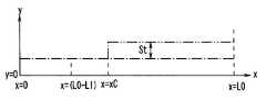
- FIG. 6shows a state in which the distal end portion of the hardness change area 2a is exposed in the distal direction more than the overtube 40, and the hardness change mechanism 20 performs the operation of increasing the hardness of the flexible tube 10 Not showing. That is, in the state shown in FIG. 6, the value of the x coordinate xC of the tip of the overtube 40 is larger than L0-L1.
- the hardness of the insertion portion 2 of the endoscopeis shown as a constant value I1 related to the x-coordinate for the purpose of explanation, but the hardness of the insertion portion 2 corresponds to the change of the x-coordinate It may change accordingly.
- I1the hardness of the insertion portion 2 of the endoscope
- FIG. 7shows a state in which the distal end of the hardness change area 2a is exposed in the distal direction more than the overtube 40, and the hardness change mechanism 20 performs the operation of increasing the hardness of the flexible tube 10 It shows the state.
- the hardness change area 2ais an area in which the x coordinate is larger than L0-L1.
- the tip of the overtube 40is located in the hardness change area 2a.
- region where hardness rises by extrapolating the overtube 40is located more proximal than the front-end
- the hardness of the first region (x ⁇ (L0-L1)) on the tip end side of the hardness change region 2ais the lowest, and then the overtube 40 of the hardness change region 2a.
- the second region ((L0 ⁇ L1) ⁇ x ⁇ xC) exposed in the distal direction more than the tip directionbecomes the intermediate hardness, and then the third region (xxxC) covered with the overtube 40 of the hardness change region 2a Hardness is the highest.
- the first area, the second area, and the third area, which increase in hardness in this order,are arranged in order from the distal end of the insertion portion 2 in the proximal direction. Therefore, in the state shown in FIG. 7, the hardness of the insertion portion 2 increases with a gradual change from the distal end toward the proximal end. Since the inclination of the change in hardness in the direction of the proximal end from the distal end of the insertion portion 2 becomes gentle, the insertability at the time of insertion of the insertion portion 2 into the subject can be improved.
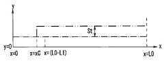
- FIG. 8shows a state in which the tip of the hardness change area 2a is covered by the overtube 40, and the hardness change mechanism 20 does not perform the operation of increasing the hardness of the flexible tube 10. That is, in the state shown in FIG. 7, the value of the x coordinate xC of the tip of the overtube 40 is smaller than L0-L1.
- FIG. 9shows a state in which the tip of the hardness change area 2a is covered by the overtube 40, and the hardness change mechanism 20 performs the operation of increasing the hardness of the flexible tube 10.
- the rising width St of the hardness by extrapolating the overtube 40is set to be equal to the rising width of the hardness of the flexible tube portion 10 by the hardness changing mechanism portion 20. Therefore, in the present embodiment, when the end of the overtube 40 is positioned closer to the end than the hardness change area 2a, as shown in FIG. 8, the hardness increase operation by the hardness change mechanism unit 20 may not be performed. The hardness of the flexible tube portion 10 can be increased.
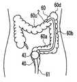
- the overtube 40is extrapolated to the insertion portion 2, and the overtube 40 is drawn to the proximal end 10 b side (the operation portion 3 side) of the flexible tube portion 10. That is, the overtube 40 is located outside the anus 61.
- the range in which the hardness change mechanism unit 20 does not raise the hardness of the flexible tube portion 10is not performed in the range inserted in the large intestine 60 of the insertion portion 2 and the overtube 40 It is the softest state with the lowest hardness because it is not broken. Therefore, the insertion portion 2 can be easily advanced in the bent S-shaped colon 60a.
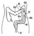
- the overtube 40is moved along the insertion portion 2 in the distal direction, and the tip of the overtube 40 reaches the S-shaped colon 60a.
- the overtube 40is positioned on the tip side of the tip of the hardness change mechanism 20.
- a gasis sent from the balloon vent 43 into the balloon 42 to inflate the balloon 42 and fix the position of the overtube 40.
- the S-shaped colon 60ais linearized by pulling the overtube 40 whose position is fixed and the insertion portion 2 whose hardness is increased. Further, the hardness of the flexible tube portion 10 is increased by the hardness change mechanism portion 20.
- the insertion portion 2 on which the hardness increase operation has been performedis pushed in, and the distal end of the insertion portion 2 is the descending colon 60b and the transverse colon 60c. Advance to splenic curvature 60d between.
- the hardness of the insertion portion 2is in a state of rising with a gradual change from the distal end toward the proximal end. That is, the distal end side of the insertion portion 2 with low hardness can be easily advanced while maintaining the hardness of the proximal end portion of the insertion portion 2 inserted into the straightened S-shaped colon 60a. .
- the distal end of the insertion portion 2is advanced into the transverse colon 60c.
- the overtube 40is moved in the distal direction along the insertion portion 2 to advance the tip of the overtube 40 to the splenic curve 60d Let And it is set as the state which does not raise operation of hardness of flexible tube part 10 by hardness change mechanism part 20.
- the hardness of the flexible tube portion 10is increased by the presence of the overtube 40, even if the hardness increasing operation by the hardness changing mechanism portion 20 is not performed.
- the shape of the linearized sigmoid colon 60ais maintained.
- the position of the overtube 40is fixed while the hardness changing operation of the hardness changing unit 20 is not performed.
- Only the insertion portion 2is advanced until the tip reaches the liver curvature 60e.
- the shape of the S-shaped colon 60a linearized by the hardness of the overtube 40is maintained, and the range inserted in the large intestine 60 of the insertion portion 2 is the flexible tube portion 10 by the hardness change mechanism portion 20.
- the insertion portioncan be easily inserted even in the transverse colon 60c in which a large amount of bending is not fixed because the operation of increasing the hardness of the lower hardness is not performed and the softest state where the hardness is not covered by the overtube 40 is low. 2 can be progressed (if it remains rigid, the inflection of the transverse colon drops largely on the anal side, making insertion difficult).
- the hardness change operation of the flexible tube 10 by the hardness change mechanism 20is performed to lift the transverse colon 60c.
- the overtube 40is moved in the distal direction along the insertion portion 2 to advance the tip of the overtube 40 to the liver curvature 60e, and then the balloon 42 is inflated to fix the position of the overtube 40.
- the shapes of the straightened S-shaped colon 60a and the lifted transverse colon 60care maintained, so the insertion portion 2 is further advanced as far as the colon.
- the operation to progress to the colon 60 fis facilitated.
- the hardness change mechanism unit 20switches the presence or absence of the operation of increasing the hardness of the flexible tube 10 and the overtube 40 to the insertion unit 2.
- the hardness change mechanism unit 20switches the presence or absence of the operation of increasing the hardness of the flexible tube 10 and the overtube 40 to the insertion unit 2.
- the large diameter portion 10c having an outer diameter larger than the outer diameter of the flexible tube portion 10is provided at a position corresponding to the tip portion of the hardness change region in the flexible tube portion 10 as the notification means.
- the proximal end 41b of the overtube 40is positioned when the distal end 41a of the overtube 40 is on the distal end of the hardness change region on the proximal end side of the flexible tube 10
- An indexmay be provided on the part. This indicator is always located outside the patient's body, so it can be easily viewed by the operator.
Landscapes
- Health & Medical Sciences (AREA)
- Life Sciences & Earth Sciences (AREA)
- Surgery (AREA)
- Biomedical Technology (AREA)
- Medical Informatics (AREA)
- Optics & Photonics (AREA)
- Pathology (AREA)
- Radiology & Medical Imaging (AREA)
- Biophysics (AREA)
- Engineering & Computer Science (AREA)
- Physics & Mathematics (AREA)
- Heart & Thoracic Surgery (AREA)
- Nuclear Medicine, Radiotherapy & Molecular Imaging (AREA)
- Molecular Biology (AREA)
- Animal Behavior & Ethology (AREA)
- General Health & Medical Sciences (AREA)
- Public Health (AREA)
- Veterinary Medicine (AREA)
- Endoscopes (AREA)
- Instruments For Viewing The Inside Of Hollow Bodies (AREA)
Abstract
Description
Translated fromJapanese本発明は、挿入部に硬度変更機構部を有する内視鏡、及びこの内視鏡とオーバーチューブとを備える内視鏡システムに関する。The present invention relates to an endoscope having a hardness changing mechanism in an insertion portion, and an endoscope system including the endoscope and an overtube.
生体の体内や構造物の内部等の観察が困難な箇所を観察するために、生体や構造物の外部から内部に挿入可能な挿入部の先端部内に、光学像を撮像するための撮像ユニットを具備した内視鏡が、例えば医療分野や工業分野において利用されている。An imaging unit for capturing an optical image in the distal end of the insertion portion that can be inserted from the outside of the living body or structure to the inside of the living body or inside of the structure, etc. An endoscope equipped is used, for example, in the medical field and the industrial field.
日本国特開平10-276965号公報に開示されている内視鏡は、挿入部の一部の曲げ方向の硬度を変更する硬度変更機構部を有する。硬度変更機構部は、挿入部内に挿通されたコイルパイプと、コイルパイプ内に挿通されたワイヤと、ワイヤを牽引することでコイルパイプに圧縮力を加える牽引機構部と、を備える。コイルパイプは、加えられる圧縮力に応じて曲げ方向の硬度が変化する。このため、挿入部のコイルパイプが挿通された部分の硬度は、コイルパイプに加えられる圧縮力に応じて変化する。The endoscope disclosed in Japanese Patent Application Laid-Open No. 10-276965 has a hardness changing mechanism portion that changes the hardness in the bending direction of a part of the insertion portion. The hardness change mechanism unit includes a coil pipe inserted into the insertion portion, a wire inserted into the coil pipe, and a pulling mechanism unit that applies a compressive force to the coil pipe by pulling the wire. The coil pipe changes its hardness in the bending direction according to the applied compression force. For this reason, the hardness of the part by which the coil pipe of the insertion part was penetrated changes according to the compressive force applied to a coil pipe.
また、日本国特開2005-334474号公報には、内視鏡の被検体内への挿入操作を補助するために、挿入部に外挿されるオーバーチューブを備えた内視鏡システムが開示されている。Also, Japanese Patent Laid-Open Publication No. 2005-334474 discloses an endoscope system provided with an overtube that is extrapolated to the insertion portion in order to assist the insertion operation of the endoscope into the subject. There is.
日本国特開平10-276965号公報に開示されている内視鏡では、挿入部のコイルパイプが挿通された領域のみ硬度が変化する。このため、硬度変更機構部により挿入部の硬度を高めた場合、挿入部の硬度が変化する領域である硬度変更領域と、この硬度変更領域を除いた領域との境界部(一般的には挿入部の先端と湾曲部との間に位置する)とで、挿入部の硬さが急激に変わることになる。In the endoscope disclosed in Japanese Patent Application Laid-Open No. 10-276965, the hardness changes only in the region where the coil pipe of the insertion portion is inserted. For this reason, when the hardness of the insertion part is increased by the hardness change mechanism part, the boundary part between the hardness change area where the hardness of the insertion part changes and the area excluding this hardness change area (generally insertion) The hardness of the insertion part changes sharply at the position between the tip of the part and the bending part).
挿入部の硬さが急激に変化する点が存在すると、挿入部を被検体内に挿入する際に、この硬さが急激に変わる点で挿入部が屈曲しやすくなるため、挿入操作の妨げとなる可能性がある。If there is a point where the hardness of the insertion part changes rapidly, when inserting the insertion part into the subject, the insertion part is easily bent at the point where the hardness changes rapidly, which hinders the insertion operation. Could be
そこで、例えばWO2017/086312号公報には硬度変更機構を備えた内視鏡にオーバーチューブを組み合わせた内視鏡システムが開示されている。この内視鏡システムでは、オーバーチューブ全体を内視鏡の挿入部に沿って前後動させ、硬度変更領域の前端にある境界部をオーバーチューブで覆う状態と露呈させた状態で選択可能にしている。これにより、境界部で挿入部の硬さを緩やかに変更した状態と急峻に変更した状態とで選択可能になっている。Therefore, for example, WO 2017/086312 discloses an endoscope system in which an overtube is combined with an endoscope provided with a hardness changing mechanism. In this endoscope system, the entire overtube is moved back and forth along the insertion portion of the endoscope to make it possible to select whether the boundary portion at the front end of the hardness change region is covered with the overtube or exposed . As a result, it is possible to select between the state in which the hardness of the insertion portion is gradually changed and the state in which the hardness of the insertion portion is changed sharply at the boundary.
しかしながら、WO2017/086312号公報に開示された内視鏡システムでは、内視鏡の挿入部を患者の体内に挿入している状態では、オーバーチューブの先端や硬度変更領域の境界部は患者の体内にあり、オーバーチューブの先端が硬度変更領域の境界部を覆っているのか露呈させているのかが目視で確認できない。However, in the endoscope system disclosed in WO 2017/086312, when the insertion portion of the endoscope is inserted into the patient's body, the tip of the overtube and the boundary portion of the hardness change region are in the patient's body. It can not be confirmed visually whether the tip of the overtube covers or exposes the boundary of the hardness change area.
本発明は、上述した点を解決するものであって、硬度変更機構部を備える内視鏡とオーバーチューブとを組み合わせて使用する場合に、硬度変更領域の先端とオーバーチューブの位置関係を容易に確認可能な内視鏡及び内視鏡システムを提供することを目的とする。The present invention solves the above-mentioned point, and when using an endoscope provided with a hardness changing mechanism and an overtube in combination, the positional relationship between the tip of the hardness changing region and the overtube can be easily made. An object of the present invention is to provide a confirmable endoscope and an endoscope system.
本発明の一態様の内視鏡は、細長に形成された挿入部と、前記挿入部の基端側を構成する可撓管部と、前記可撓管部の管内に設けられ手元側の操作により前記可撓管部の硬度を変更する硬度変更機構部と、前記可撓管部の外周に設けられ、前記硬度変更機構部による前記可撓管部の硬度変更領域の先端を示す指標と、を備えている。An endoscope according to one aspect of the present invention includes an elongated insertion portion, a flexible tube portion constituting a proximal end side of the insertion portion, and an operation on the proximal side provided in a tube of the flexible tube portion. A hardness change mechanism that changes the hardness of the flexible tube, and an index that is provided on the outer periphery of the flexible tube and indicates the tip of the hardness change area of the flexible tube by the hardness change mechanism; Is equipped.
本発明の他の態様の内視鏡システムは、細長に形成された挿入部と、前記挿入部の基端側を構成する可撓管部と、前記可撓管部の管内に設けられ前記可撓管部の硬度を変更する硬度変更機構部と、を備え、前記硬度変更機構部による前記可撓管部の硬度変更領域が前記可撓管部の中途部分から基端部分に至るよう設定された内視鏡と、可撓性を備え軸方向に延びる筒状であり、内部に前記挿入部が摺動自在に挿入されると共に、軸方向の全長が前記硬度変更領域の全長よりも短く形成され、軸方向の基端部が前記内視鏡の挿入部の最も基端側に位置する際に前記硬度変更領域の先端部を露出させるオーバーチューブと、前記内視鏡に設けられ、前記オーバーチューブの先端が前記硬度変更領域の先端を通過したことを告知する告知手段と、を備えている。An endoscope system according to another aspect of the present invention is provided in an elongated tube, a flexible tube forming a proximal end side of the insert, and a tube of the flexible tube. A hardness change mechanism unit for changing the hardness of the flexible tube portion, wherein the hardness change region of the flexible tube portion by the hardness change mechanism portion is set to extend from the middle portion to the proximal end portion of the flexible tube portion The endoscope has a flexible, axially extending cylindrical shape, and the insertion portion is slidably inserted therein, and the entire length in the axial direction is shorter than the entire length of the hardness change area An overtube for exposing the distal end portion of the hardness change region when the proximal end portion in the axial direction is positioned on the most proximal side of the insertion portion of the endoscope; Notification means for notifying that the tip of the tube has passed the tip of the hardness change area; It is provided.
以下に、本発明の好ましい形態について図面を参照して説明する。なお、以下の説明に用いる各図においては、各構成要素を図面上で認識可能な程度の大きさとするため、構成要素毎に縮尺を異ならせてあるものであり、本発明は、これらの図に記載された構成要素の数量、構成要素の形状、構成要素の大きさの比率、及び各構成要素の相対的な位置関係のみに限定されるものではない。Hereinafter, preferred embodiments of the present invention will be described with reference to the drawings. In the drawings used in the following description, the scale of each component is different in order to make each component have a size that can be recognized in the drawings, and the present invention is not limited to these drawings. The present invention is not limited only to the number of components described in the above, the shape of the components, the ratio of the size of the components, and the relative positional relationship between the components.
図1に示す本実施形態の内視鏡システム50は、内視鏡1とオーバーチューブ40を備える。内視鏡1は、人体等の被検体内に導入可能な細長の挿入部2を有し、挿入部2に被検体内を観察するための構成を有する。なお、内視鏡1の挿入部2が導入される被検体は、人体に限らず、他の生体であってもよい。An
本実施形態の内視鏡1は、被検体の内部に導入される細長に形成された挿入部2と、挿入部2の基端に位置する操作部3と、操作部3から延出するユニバーサルコード4とで主に構成されている。The
挿入部2は、先端に配設される先端部8、先端部8の基端側に配設される湾曲自在な湾曲部9、及び湾曲部9の基端側と操作部3の先端側とを接続する可撓性を有する可撓管部10が連設されて構成されている。The
先端部8には、被検体内を観察するための構成等が配設されている。例えば、先端部8には、対物レンズ及び撮像素子を含み光学的に被検体内を観察するための撮像ユニットが配設されている。また、先端部8には、図示しないが、撮像ユニットの被写体を照明する光を出射する照明光出射部も設けられている。なお、先端部8には、超音波を用いて音響的に被検体内を観察するための超音波振動子が配設されていてもよい。The
挿入部2の基端に配設された操作部3には、湾曲部9の湾曲を操作するためのアングル操作ノブ6が設けられている。ユニバーサルコード4の基端部には図示しない外部装置に接続可能に構成された内視鏡コネクタ5が設けられている。内視鏡コネクタ5が接続される外部装置は、先端部8に設けられた撮像ユニットを制御するカメラコントロールユニット等を備える。The
また、操作部3には、可撓管部10内に配設された硬度変更機構部20を操作するための硬度変更ノブ21が設けられている。硬度変更機構部20は、可撓管部10の長手方向に沿って可撓管部10内に挿入されており、硬度変更ノブ21による操作入力に応じて、屈曲に対する硬度が変化する構成を有する。すなわち、硬度変更機構部20は、可撓管部10の屈曲に対する硬度を変化させる。Further, the
硬度変更機構部20の構成は公知であるため、詳細な説明は省略するが、硬度変更機構部20は、図3に示すように、コイルパイプ22、第1ワイヤ24および第2ワイヤ26および牽引機構部30を備える。挿入部2および硬度変更機構部20を構成する部材について、挿入部2の先端部8側に向かう方向を先端方向と称し、操作部3側に向かう方向を基端方向と称する。The configuration of the
コイルパイプ22は、例えばステンレス合金等の金属製の線状の素線を、挿入部2の長手方向に平行な所定の軸A周りに螺旋状に巻回して形成された線状部材である。コイルパイプ22の基端22bは、操作部3内に設けられたコイル固定部23に固定されている。The
また、コイルパイプ22の先端22aは、可撓管部10内の可撓管部10の先端10aよりも所定距離だけ基端方向に配置されている。すなわち、コイルパイプ22は、可撓管部10内において、可撓管部10の基端10bから可撓管部10の先端10aよりも手前まで延在している。Further, the
コイルパイプ22内には、第1ワイヤ24が挿通されている。第1ワイヤ24は、先端24aがコイルパイプ22の先端22aに固定されており、基端24bが後述する牽引機構部30のワイヤ保持部30aに固定されている。The
本実施形態では一例として、第1ワイヤ24の先端24aは、コイルパイプ22の先端22aに固着される接続部25に固定されている。なお、第1ワイヤ24の先端24aは、直接的にコイルパイプ22の先端22aに固定されていてもよい。In the present embodiment, as an example, the
第2ワイヤ26は、先端26aが湾曲部9の基端側の枠部材9aに設けられたワイヤ固定部28に固定されており、基端26bが接続部25に固定されている。第2ワイヤ26は、コイルパイプ22の先端22aが可撓管部10内において基端方向に移動することを規制し、コイルパイプ22の可撓管部10内における長手方向の位置を保持する。また、可撓管部10の外表面において、コイルパイプ22の先端部が内側に位置する箇所には、糸を巻いた後にこの糸巻き部分を接着剤で覆って形成した、指標として機能する大径部10cが配置されている。この大径部10cの外径は、オーバーチューブ40の筒状部41の先端部41aの内径より若干大きく(例えば0.5~1.0mm程度大きく)なるよう構成されている。A
牽引機構部30は、操作部3に対して回動する硬度変更ノブ21と、第1ワイヤ24の基端24bを保持し硬度変更ノブ21の回動に応じて軸Aに沿う方向に進退移動するワイヤ保持部30aと、を備える。The pulling
硬度変更ノブ21の内周面には、カム溝21bが彫設されている。ワイヤ保持部30aには、カム溝21bに摺動可能に係合するカムピン30bが設けられている。カム溝21bとカムピン30bとの係合により、ワイヤ保持部30aは、硬度変更ノブ21の回動に応じて軸Aに沿う方向に進退移動する。以上のように構成された、本実施形態の牽引機構部30は、使用者による硬度変更ノブ21の回動操作に応じて、第1ワイヤ24を基端方向に牽引し、第1ワイヤ24に加える張力を変更することができる。A
牽引機構部30によって第1ワイヤ24に加えられる張力に応じて、コイルパイプ22には圧縮力が加えられる。コイルパイプ22は、圧縮力が加えられることにより曲げ変形に対する抵抗力が大きくなる。よって、可撓管部10のコイルパイプ22が内部に配置されている範囲の屈曲に対する硬度は、コイルパイプ22の曲げ変形に対する抵抗力に応じて変化する。以上に説明した構成により、硬度変更機構部20は、可撓管部10のコイルパイプ22が挿通されている部分の硬度を変更する。A compressive force is applied to the
本実施形態においては、可撓管部10を直線状に保持した場合における、可撓管部10の基端10bからコイルパイプ22の先端までの長さはL1である。したがって、本実施形態の内視鏡1の挿入部2では、可撓管部10の基端10bから長手方向に沿って先端方向に向かって長さL1の範囲が、硬度変更機構部20によって硬度の変更が可能な硬度変更領域2aである。In the present embodiment, the length from the
オーバーチューブ40は、可撓性を有する筒状の筒状部41を備えている。筒状部41は、両端が開口する筒形状であり、図2に示すように、内部に内視鏡1の挿入部2を挿通することができる。言い換えれば、筒状部41は、挿入部2の外周に被せることができる。筒状部41は、内部に挿入部2が挿入されている状態においては、挿入部2の変形に応じて屈曲する。また、筒状部41は、挿入部2に対して相対的に挿入部2の長手方向に沿って摺動可能である。筒状部41の先端部における内径は、前述した可撓管部10の外径に対して摺動する程度の外径で、かつ、可撓管部10の大径部10cにおける外径より若干小さく(例えば0.5mm~1.0mm程度小さく)なるよう形成される。この筒状部41の先端部における内径は、可撓管部10の外周を摺動する際にはなるべく摺動抵抗が小さくなるよう、そして大径部10cを乗り越える際には操作者の手元にて若干の抵抗を感じる程度の大きさに設定すれば良い。The
図2は、筒状部41を、挿入部2に対して最も基端方向に配置した状態を示している。すなわち、図2は、オーバーチューブ40内に内視鏡1の挿入部2を最も押し込んだ状態を示している。FIG. 2 shows a state in which the
図1および図2に示すように、筒状部41の軸方向(長手方向)の長さL2は、硬度変更領域2aの長さL1よりも短い。As shown to FIG. 1 and FIG. 2,
したがって、図2及び図4に示すように筒状部41を、挿入部2に対して最も基端方向に配置した場合には、可撓管部10に設けられた硬度変更領域2aの先端部が、オーバーチューブ40の筒状部41の先端部41aよりも先端方向に突出する。言い換えれば、挿入部2をオーバーチューブ40の筒状部41に最も押し込んだ場合には、硬度変更領域2aの先端部が、筒状部41から先端方向に露出する。Therefore, as shown in FIGS. 2 and 4, when the
筒状部41の先端部41aには、伸縮可能な部材からなるバルーン42が配設されている。また、筒状部41の基端部41bには、図示しない管路を介してバルーン42内に連通するバルーン通気口43が配設されている。バルーン42は、筒状部41の先端部41aの外周を囲うように配置されたドーナツ形状を有している。バルーン42は、バルーン通気口43を介した気体の出し入れに応じて膨張または収縮する。At the
以上に説明したように、本実施形態の内視鏡システム50では、オーバーチューブ40の挿入部2に外挿される筒状部41の全長L2が、挿入部2の硬度変更領域2aの長さL1よりも短い。したがって、本実施形態の内視鏡システム50では、オーバーチューブ40を挿入部2に外挿した状態において、オーバーチューブ40と挿入部2との長手方向の相対位置を変化させることによって、硬度変更領域2aの先端部がオーバーチューブ40よりも先端方向に露出した状態と、硬度変更領域2aの先端部がオーバーチューブ40により覆われている状態と、を選択することができる。As described above, in the
例えば図4に示すように、オーバーチューブ40に対して挿入部2を相対的に先端方向へ押し込めば、硬度変更領域2aの先端部がオーバーチューブ40よりも先端方向に露出する。また例えば、図5に示すように、オーバーチューブ40に対して挿入部2を相対的に基端方向へ引き戻せば、硬度変更領域2aの先端部がオーバーチューブ40により覆われる。図4から図5に示すように挿入部2を相対的に基端方向に引き戻す際には、オーバーチューブ40の筒状部41の先端部41aが可撓管部10の大径部10cを乗り越えて挿入部2の先端側に移動する。これにより、操作者は手元の感触から、オーバーチューブ40の筒状部41の先端部41aが硬度変更領域2aよりも先端側に移動したことが解る。For example, as shown in FIG. 4, when the
図6、図7、図8および図9には、長手方向についての挿入部2およびオーバーチューブ40の硬さの変化の様子を示す。図6、図7、図8および図9に示す模式的なグラフにおいて、横軸であるx軸は、挿入部2の先端からの長手方向の距離を示している。また、縦軸であるy軸は、挿入部2およびオーバーチューブ40の曲げ方向の変形に対する硬さを示している。FIGS. 6, 7, 8 and 9 show changes in the hardness of the
x軸において、x=0が挿入部2の先端であり、x=L0が挿入部2の基端(可撓管部10の基端10b)である。また、y軸においては、図中の上に向かうほど硬さが高くなる。また、図中の一点鎖線は、挿入部2の硬さを示し、二点鎖線はオーバーチューブ40の硬さを示している。同一のx座標において、挿入部2の硬さと、オーバーチューブ40の硬さを積算した値が、当該x座標における内視鏡システム50の挿入部2の硬さを示す。In the x-axis, x = 0 is the tip of the
そして、図6は、硬度変更領域2aの先端部がオーバーチューブ40よりも先端方向に露出した状態であって、かつ硬度変更機構部20による可撓管部10の硬さの上昇操作が行われていない状態を示している。すなわち、図6に示す状態では、オーバーチューブ40の先端のx座標xCの値が、L0-L1よりも大きい。6 shows a state in which the distal end portion of the
図6に示すように、オーバーチューブ40が外挿されている領域(x≧xC)においては、挿入部2の硬さにオーバーチューブ40の筒状部41の硬さStが合成されるため、硬さが高くなる。As shown in FIG. 6, in the region (xxxC) where the
なお、図6では、説明のために内視鏡の挿入部2の硬さがx座標に関わらす一定の値I1であるとして示してあるが、挿入部2の硬さはx座標の変化に応じて変化してもよい。これは、図7、図8および図9についても同様である。In FIG. 6, the hardness of the
図7は、硬度変更領域2aの先端部がオーバーチューブ40よりも先端方向に露出した状態であって、かつ硬度変更機構部20による可撓管部10の硬さの上昇操作が行われている状態を示している。FIG. 7 shows a state in which the distal end of the
図7に示す状態では、挿入部2の硬度変更領域2aの硬度が上昇している。硬度変更領域2aとは、x座標がL0-L1よりも大きい領域である。図7に示す状態では、オーバーチューブ40の先端が、この硬度変更領域2a内に位置している。In the state shown in FIG. 7, the hardness of the
すなわち、オーバーチューブ40が外挿されることによって硬さが上昇する領域は、硬度変更領域2aの先端よりも基端側に位置している。このため、図7に示す状態では、硬度変更領域2aよりも先端側の第1領域(x<(L0-L1))の硬さが最も低く、次に硬度変更領域2aのうちのオーバーチューブ40よりも先端方向に露出した第2領域((L0-L1)≦x<xC)が中間の硬さとなり、次に硬度変更領域2aのオーバーチューブ40に覆われた第3領域(x≧xC)の硬さが最も高くなる。That is, the area | region where hardness rises by extrapolating the
この順に硬さが高くなる第1領域、第2領域、および第3領域は、挿入部2の先端から基端方向に向かって順に配置されている。したがって、図7に示す状態では、挿入部2は先端から基端方向に向かって緩やかな変化で硬さが上昇する。挿入部2の先端から基端方向に向かう硬さの変化の傾きが緩やかになることで、挿入部2の被検体内への挿入時の挿入性を向上させることができる。The first area, the second area, and the third area, which increase in hardness in this order, are arranged in order from the distal end of the
図8は、硬度変更領域2aの先端部がオーバーチューブ40により覆われており、かつ硬度変更機構部20による可撓管部10の硬さの上昇操作が行われていない状態を示している。すなわち、図7に示す状態では、オーバーチューブ40の先端のx座標xCの値が、L0-L1よりも小さい。FIG. 8 shows a state in which the tip of the
図9は、硬度変更領域2aの先端部がオーバーチューブ40により覆われており、かつ硬度変更機構部20による可撓管部10の硬さの上昇操作が行われている状態を示している。FIG. 9 shows a state in which the tip of the
本実施形態では、オーバーチューブ40を外挿することによる硬さの上昇幅Stが、硬度変更機構部20による可撓管部10の硬さの上昇幅と同等となるように設定されている。したがって、本実施形態においてオーバーチューブ40の先端を硬度変更領域2aよりも先端側に位置させた場合には、図8に示すように、硬度変更機構部20による硬度上昇操作を行わなくても可撓管部10の硬度を上昇させることができる。In the present embodiment, the rising width St of the hardness by extrapolating the
次に、本実施形態の内視鏡システム50を用いて、被検体である人体の大腸60内に、内視鏡1の挿入部2を、肛門61を経由して挿入する方法を図10から図17を用いて説明する。Next, a method of inserting the
まず、第1ステップにおいて、図10に示すように、肛門61から内視鏡1の挿入部2のみを、硬度変更機構部20による可撓管部10の硬さの上昇操作を行わない状態で、先端が大腸60のS字状結腸60aに達するまで挿入する。この時、挿入部2にはオーバーチューブ40を外挿しておき、かつオーバーチューブ40は、可撓管部10の基端10b側(操作部3側)に引き寄せた状態としておく。すなわち、オーバーチューブ40は、肛門61よりも外側に位置している。First, in the first step, as shown in FIG. 10, only the
第1ステップでは、挿入部2の大腸60内に挿入されている範囲は、硬度変更機構部20による可撓管部10の硬さの上昇操作が行われておらず、かつオーバーチューブ40により覆われていないため、最も硬さが低い柔らかい状態である。このため、屈曲の多いS字状結腸60a内において容易に挿入部2を進行させることができる。In the first step, the range in which the hardness
次に第2ステップにおいて、図11に示すように、オーバーチューブ40を、挿入部2に沿って先端方向へ移動させ、オーバーチューブ40の先端をS字状結腸60aにまで到達させる。ここで、オーバーチューブ40は、硬度変更機構部20の先端よりも先端側に位置させる。この操作により、図8に示すようにオーバーチューブ40に覆われた挿入部2の硬度が上昇する。Next, in a second step, as shown in FIG. 11, the
そして、バルーン通気口43からバルーン42内に気体を送り込み、バルーン42を膨張させ、オーバーチューブ40の位置を固定する。Then, a gas is sent from the
次に第3ステップにおいて、図12に示すように、位置を固定したオーバーチューブ40と硬度が上昇した挿入部2を引くことにより、S字状結腸60aが直線化する。さらに硬度変更機構部20による可撓管部10の硬さの上昇操作を行う。Next, in the third step, as shown in FIG. 12, the S-shaped
次に第4ステップにおいて、図13に示すように、オーバーチューブ40の位置を固定したまま、硬度上昇操作が行われた挿入部2を押し込み、挿入部2の先端を下行結腸60bと横行結腸60cとの間の脾湾曲60dまで進行させる。このとき、図7に示すように、挿入部2の硬さは、先端から基端方向に向かって緩やかな変化で上昇する状態である。すなわち、挿入部2の直線化したS字状結腸60a内に挿通されている基端側の部分の硬さを維持したまま、硬度の低い挿入部2の先端側を容易に進行させることができる。Next, in the fourth step, as shown in FIG. 13, with the position of the
そして、第5ステップにおいて、図14に示すように、挿入部2の先端を横行結腸60c内にまで進行させる。Then, in the fifth step, as shown in FIG. 14, the distal end of the
次に、第6ステップにおいて、図15に示すように、バルーン42を収縮させた後に、オーバーチューブ40を挿入部2に沿って先端方向へ移動させ、オーバーチューブ40の先端を脾湾曲60dまで進行させる。そして、硬度変更機構部20による可撓管部10の硬さの上昇操作を行わない状態とする。Next, in the sixth step, as shown in FIG. 15, after the
このとき、図8に示すように、硬度変更機構部20による硬度上昇操作を行わなくても、可撓管部10の硬度はオーバーチューブ40の存在によって上昇した状態となる。したがって、直線化したS字状結腸60aの形状は維持される。At this time, as shown in FIG. 8, the hardness of the
次に、第7ステップにおいて、図16に示すように、硬度変更機構部20による可撓管部10の硬さの上昇操作が行われていない状態で、オーバーチューブ40の位置を固定しつつ、挿入部2のみを先端が肝湾曲60eに到達するまで進行させる。このとき、オーバーチューブ40の硬度によって直線化したS字状結腸60aの形状が維持されるとともに挿入部2の大腸60内に挿入されている範囲は、硬度変更機構部20による可撓管部10の硬さの上昇操作が行われておらず、かつオーバーチューブ40により覆われていない最も硬さが低い柔らかい状態であるため、屈曲が多く固定されていない横行結腸60c内においても容易に挿入部2を進行させることができる(硬いままだと横行結腸は屈曲部が肛門側に大きく下垂してしまい挿入が難しい)。Next, in the seventh step, as shown in FIG. 16, the position of the
次に第8ステップにおいて、図17に示すように、硬度変更機構部20による可撓管部10の硬さの上昇操作を行い、横行結腸60cを持ち上げる。そして、オーバーチューブ40を挿入部2に沿って先端方向へ移動させ、オーバーチューブ40の先端を肝湾曲60eまで進行させた後に、バルーン42を膨張させてオーバーチューブ40の位置を固定する。Next, in an eighth step, as shown in FIG. 17, the hardness change operation of the
オーバーチューブ40の先端が肝湾曲60e近傍に固定されることにより、直線化したS字状結腸60aおよび持ち上げた横行結腸60cの形状が維持されるため、挿入部2を大腸のさらに奥である上行結腸60fへ進行させる操作が容易となる。By fixing the tip of the
以上に説明したように、本実施形態の内視鏡システム50は、硬度変更機構部20による可撓管部10の硬さの上昇操作の有無の切り替えと、オーバーチューブ40を挿入部2に対して長手方向に相対的に進退移動を組み合わせて様々な硬度設定を行なう際に、硬度変更領域の先端とオーバーチューブ40の位置関係を容易に確認可能となる。As described above, in the
以上述べた実施形態では、告知手段として、可撓管部10における硬度変更領域の先端部分に対応する位置に、可撓管部10の外径よりも大きな外径を有する大径部10cを設けている。告知手段の他の手段としては、例えば、可撓管部10基端側に、オーバーチューブ40の先端部41aが硬度変更領域の先端上にある際にオーバーチューブ40の基端部41bが位置する部分に指標を設けるようにしても良い。この指標は、常に患者の体外に位置するため、操作者により容易に視認が可能となる。In the embodiment described above, the
本発明は、上述した実施形態に限られるものではなく、請求の範囲及び明細書全体から読み取れる発明の要旨或いは思想に反しない範囲で適宜変更可能であり、そのような変更を伴う内視鏡システムもまた本発明の技術的範囲に含まれるものである。The present invention is not limited to the embodiments described above, and can be appropriately modified without departing from the scope or spirit of the invention as can be read from the claims and the entire specification, and an endoscope system with such modifications. Also within the technical scope of the present invention.
本発明は、2017年12月28日に日本国に出願された特願2017-253118号を優先権主張の基礎として出願するものであり、上記の内容は、本願明細書、請求の範囲、図面に引用されたものである。The present invention is based on Japanese Patent Application No. 2017-253118 filed on Dec. 28, 2017 as a basis for claiming priority, and the contents described above are the present specification, claims and drawings. Cited in the
Claims (11)
Translated fromJapanese前記挿入部の基端側を構成する可撓管部と、
前記可撓管部の管内に設けられ手元側の操作により前記可撓管部の硬度を変更する硬度変更機構部と、
前記可撓管部の外周に設けられ、前記硬度変更機構部による前記可撓管部の硬度変更領域の先端を示す指標と、
を具備することを特徴とする内視鏡。An elongated insertion part,
A flexible tube portion constituting a proximal end side of the insertion portion;
A hardness change mechanism provided in the tube of the flexible tube and changing the hardness of the flexible tube by an operation on the hand side;
An index, which is provided on the outer periphery of the flexible tube, and indicates the tip of the hardness change area of the flexible tube by the hardness change mechanism;
An endoscope characterized in that it comprises.
可撓性を備え軸方向に延びる筒状であり、内部に前記挿入部が摺動自在に挿入されると共に、軸方向の全長が前記硬度変更領域の全長よりも短く形成され、軸方向の基端部が前記内視鏡の挿入部の最も基端側に位置する際に前記硬度変更領域の先端部を露出させるオーバーチューブと、
前記内視鏡に設けられ、前記オーバーチューブの先端が前記硬度変更領域の先端を通過したことを告知する告知手段と、
を備えたことを特徴とする内視鏡システム。An elongated insertion portion, a flexible tube forming the proximal end side of the insertion portion, and a hardness changing mechanism provided in the tube of the flexible tube to change the hardness of the flexible tube; An endoscope, wherein the hardness change area of the flexible tube by the hardness change mechanism is set to extend from the middle portion to the proximal end of the flexible tube.
A flexible, axially extending cylindrical member having the insertion portion slidably inserted therein, and having a total axial length shorter than that of the hardness change region, and an axial base An overtube which exposes the distal end of the hardness change region when the end is positioned most proximal to the insertion portion of the endoscope;
A notification unit provided in the endoscope to notify that the tip of the overtube has passed the tip of the hardness change area;
An endoscope system characterized by comprising.
Priority Applications (3)
| Application Number | Priority Date | Filing Date | Title |
|---|---|---|---|
| CN201880080891.2ACN111479493B (en) | 2017-12-28 | 2018-08-06 | Endoscope and endoscope system |
| JP2019562732AJP6751824B2 (en) | 2017-12-28 | 2018-08-06 | Endoscope and endoscope system |
| US16/911,454US20200323421A1 (en) | 2017-12-28 | 2020-06-25 | Endoscope and endoscope system |
Applications Claiming Priority (2)
| Application Number | Priority Date | Filing Date | Title |
|---|---|---|---|
| JP2017253118 | 2017-12-28 | ||
| JP2017-253118 | 2017-12-28 |
Related Child Applications (1)
| Application Number | Title | Priority Date | Filing Date |
|---|---|---|---|
| US16/911,454ContinuationUS20200323421A1 (en) | 2017-12-28 | 2020-06-25 | Endoscope and endoscope system |
Publications (1)
| Publication Number | Publication Date |
|---|---|
| WO2019130639A1true WO2019130639A1 (en) | 2019-07-04 |
Family
ID=67063030
Family Applications (1)
| Application Number | Title | Priority Date | Filing Date |
|---|---|---|---|
| PCT/JP2018/029376CeasedWO2019130639A1 (en) | 2017-12-28 | 2018-08-06 | Endoscope and endoscope system |
Country Status (4)
| Country | Link |
|---|---|
| US (1) | US20200323421A1 (en) |
| JP (1) | JP6751824B2 (en) |
| CN (1) | CN111479493B (en) |
| WO (1) | WO2019130639A1 (en) |
Families Citing this family (9)
| Publication number | Priority date | Publication date | Assignee | Title |
|---|---|---|---|---|
| WO2018098465A1 (en) | 2016-11-28 | 2018-05-31 | Inventio, Inc. | Endoscope with separable, disposable shaft |
| JP7112435B2 (en)* | 2020-01-09 | 2022-08-03 | Hoya株式会社 | Endoscope |
| USD1018844S1 (en) | 2020-01-09 | 2024-03-19 | Adaptivendo Llc | Endoscope handle |
| USD1051380S1 (en) | 2020-11-17 | 2024-11-12 | Adaptivendo Llc | Endoscope handle |
| USD1070082S1 (en) | 2021-04-29 | 2025-04-08 | Adaptivendo Llc | Endoscope handle |
| USD1031035S1 (en) | 2021-04-29 | 2024-06-11 | Adaptivendo Llc | Endoscope handle |
| USD1066659S1 (en) | 2021-09-24 | 2025-03-11 | Adaptivendo Llc | Endoscope handle |
| EP4427660A1 (en)* | 2023-03-10 | 2024-09-11 | Ambu A/S | Endoscope with variable stiffness |
| CN116369829B (en)* | 2023-06-06 | 2023-09-08 | 新光维医疗科技(苏州)股份有限公司 | Endoscope, imaging system, and endoscope control method |
Citations (3)
| Publication number | Priority date | Publication date | Assignee | Title |
|---|---|---|---|---|
| JPH1189790A (en)* | 1997-09-25 | 1999-04-06 | Olympus Optical Co Ltd | Endoscope device |
| JP2012070854A (en)* | 2010-09-28 | 2012-04-12 | Hoya Corp | Surgical endoscopic device |
| WO2017086312A1 (en)* | 2015-11-20 | 2017-05-26 | オリンパス株式会社 | Endoscope system |
Family Cites Families (18)
| Publication number | Priority date | Publication date | Assignee | Title |
|---|---|---|---|---|
| JPH05285090A (en)* | 1992-04-13 | 1993-11-02 | Asahi Optical Co Ltd | Mounting method of cover tube of bending part for endoscope |
| US5885208A (en)* | 1996-12-24 | 1999-03-23 | Olympus Optical Co., Ltd. | Endoscope system |
| JP3776557B2 (en)* | 1997-04-10 | 2006-05-17 | オリンパス株式会社 | Endoscope |
| JP3969678B2 (en)* | 1997-05-01 | 2007-09-05 | 幸士 生田 | Variable stiffness type cable |
| JP4629213B2 (en)* | 2000-11-24 | 2011-02-09 | Hoya株式会社 | Endoscope outer tube mounting structure and endoscope outer tube mounting method |
| JP4681752B2 (en)* | 2001-05-08 | 2011-05-11 | Hoya株式会社 | Endoscope bending stiffness adjuster |
| JP4772208B2 (en)* | 2001-05-10 | 2011-09-14 | オリンパス株式会社 | Endoscope |
| JP2002360504A (en)* | 2001-06-04 | 2002-12-17 | Pentax Corp | Flexible endoscope |
| JP4172966B2 (en)* | 2002-08-08 | 2008-10-29 | Hoya株式会社 | Endoscope hardness variable sheath adapter |
| JP3864344B2 (en)* | 2003-12-05 | 2006-12-27 | フジノン株式会社 | Endoscope insertion aid |
| JP2005237817A (en)* | 2004-02-27 | 2005-09-08 | Olympus Corp | Endoscope |
| JP4323441B2 (en)* | 2005-02-14 | 2009-09-02 | オリンパス株式会社 | Endoscope |
| JP2008035909A (en)* | 2006-08-01 | 2008-02-21 | Olympus Medical Systems Corp | Endoscope insertion aid |
| JP5810037B2 (en)* | 2012-06-04 | 2015-11-11 | オリンパス株式会社 | Endoscope system |
| WO2015029503A1 (en)* | 2013-08-30 | 2015-03-05 | オリンパスメディカルシステムズ株式会社 | Endoscope |
| CN107205616B (en)* | 2015-01-28 | 2019-04-23 | 奥林巴斯株式会社 | Flexible pipe insertion apparatus |
| JP2016187382A (en)* | 2015-03-30 | 2016-11-04 | Hoya株式会社 | Tip connection structure of endoscope insertion part |
| JP6444809B2 (en)* | 2015-06-05 | 2018-12-26 | 富士フイルム株式会社 | Endoscope system |
- 2018
- 2018-08-06JPJP2019562732Apatent/JP6751824B2/enactiveActive
- 2018-08-06CNCN201880080891.2Apatent/CN111479493B/enactiveActive
- 2018-08-06WOPCT/JP2018/029376patent/WO2019130639A1/ennot_activeCeased
- 2020
- 2020-06-25USUS16/911,454patent/US20200323421A1/ennot_activeAbandoned
Patent Citations (3)
| Publication number | Priority date | Publication date | Assignee | Title |
|---|---|---|---|---|
| JPH1189790A (en)* | 1997-09-25 | 1999-04-06 | Olympus Optical Co Ltd | Endoscope device |
| JP2012070854A (en)* | 2010-09-28 | 2012-04-12 | Hoya Corp | Surgical endoscopic device |
| WO2017086312A1 (en)* | 2015-11-20 | 2017-05-26 | オリンパス株式会社 | Endoscope system |
Also Published As
| Publication number | Publication date |
|---|---|
| JP6751824B2 (en) | 2020-09-09 |
| JPWO2019130639A1 (en) | 2020-09-03 |
| CN111479493B (en) | 2023-04-25 |
| CN111479493A (en) | 2020-07-31 |
| US20200323421A1 (en) | 2020-10-15 |
Similar Documents
| Publication | Publication Date | Title |
|---|---|---|
| JP6423539B2 (en) | Endoscope system | |
| WO2019130639A1 (en) | Endoscope and endoscope system | |
| CA2898586C (en) | Integrated steering device | |
| JP5917467B2 (en) | Endoscope | |
| CN107405045B (en) | Flexible pipe insertion device | |
| US9872607B2 (en) | Endoscope | |
| JPWO2006123590A1 (en) | ENDOSCOPE SYSTEM, ENDOSCOPE SYSTEM CONTROL PROGRAM, AND ENDOSCOPE SYSTEM CONTROL METHOD | |
| JP2009219821A (en) | Endoscope | |
| JP2006068393A (en) | Endoscope | |
| JP6444809B2 (en) | Endoscope system | |
| US10485410B2 (en) | Flexible tube insertion apparatus | |
| US10156304B2 (en) | Flexible tube and insertion device | |
| US20240237889A1 (en) | Endoscope having tension adjustment part | |
| JP3923701B2 (en) | Endoscope | |
| JP6203455B1 (en) | Endoscope system | |
| WO2018122976A1 (en) | Flexible pipe insertion apparatus | |
| JP3698844B2 (en) | Endoscope | |
| JP3934593B2 (en) | Endoscope system | |
| EP3260034A1 (en) | Endoscope system | |
| CN108348138A (en) | Endoscope with a detachable handle | |
| JP5161420B2 (en) | Endoscope insertion part | |
| JP2010035759A (en) | Endoscope | |
| JP5797363B1 (en) | Coil structure used for endoscope, endoscope and treatment tool provided with this coil structure | |
| JPH0445177B2 (en) | ||
| JP2024173018A (en) | Endoscope tube and endoscope |
Legal Events
| Date | Code | Title | Description |
|---|---|---|---|
| 121 | Ep: the epo has been informed by wipo that ep was designated in this application | Ref document number:18895535 Country of ref document:EP Kind code of ref document:A1 | |
| ENP | Entry into the national phase | Ref document number:2019562732 Country of ref document:JP Kind code of ref document:A | |
| NENP | Non-entry into the national phase | Ref country code:DE | |
| 122 | Ep: pct application non-entry in european phase | Ref document number:18895535 Country of ref document:EP Kind code of ref document:A1 |