WO2019124626A1 - Vehicle reception apparatus for receiving broadcast signal and vehicle reception method for receiving broadcast signal - Google Patents
Vehicle reception apparatus for receiving broadcast signal and vehicle reception method for receiving broadcast signalDownload PDFInfo
- Publication number
- WO2019124626A1 WO2019124626A1PCT/KR2018/000855KR2018000855WWO2019124626A1WO 2019124626 A1WO2019124626 A1WO 2019124626A1KR 2018000855 WKR2018000855 WKR 2018000855WWO 2019124626 A1WO2019124626 A1WO 2019124626A1
- Authority
- WO
- WIPO (PCT)
- Prior art keywords
- frame
- data
- vehicle
- size
- encoder
- Prior art date
- Legal status (The legal status is an assumption and is not a legal conclusion. Google has not performed a legal analysis and makes no representation as to the accuracy of the status listed.)
- Ceased
Links
Images


Classifications
- H—ELECTRICITY
- H04—ELECTRIC COMMUNICATION TECHNIQUE
- H04N—PICTORIAL COMMUNICATION, e.g. TELEVISION
- H04N21/00—Selective content distribution, e.g. interactive television or video on demand [VOD]
- H04N21/40—Client devices specifically adapted for the reception of or interaction with content, e.g. set-top-box [STB]; Operations thereof
- H04N21/41—Structure of client; Structure of client peripherals
- H04N21/414—Specialised client platforms, e.g. receiver in car or embedded in a mobile appliance
- H04N21/41407—Specialised client platforms, e.g. receiver in car or embedded in a mobile appliance embedded in a portable device, e.g. video client on a mobile phone, PDA, laptop
- H—ELECTRICITY
- H04—ELECTRIC COMMUNICATION TECHNIQUE
- H04B—TRANSMISSION
- H04B1/00—Details of transmission systems, not covered by a single one of groups H04B3/00 - H04B13/00; Details of transmission systems not characterised by the medium used for transmission
- H04B1/06—Receivers
- H04B1/16—Circuits
- H—ELECTRICITY
- H04—ELECTRIC COMMUNICATION TECHNIQUE
- H04W—WIRELESS COMMUNICATION NETWORKS
- H04W4/00—Services specially adapted for wireless communication networks; Facilities therefor
- H04W4/30—Services specially adapted for particular environments, situations or purposes
- H04W4/40—Services specially adapted for particular environments, situations or purposes for vehicles, e.g. vehicle-to-pedestrians [V2P]
- H—ELECTRICITY
- H04—ELECTRIC COMMUNICATION TECHNIQUE
- H04H—BROADCAST COMMUNICATION
- H04H20/00—Arrangements for broadcast or for distribution combined with broadcast
- H04H20/53—Arrangements specially adapted for specific applications, e.g. for traffic information or for mobile receivers
- H—ELECTRICITY
- H04—ELECTRIC COMMUNICATION TECHNIQUE
- H04H—BROADCAST COMMUNICATION
- H04H40/00—Arrangements specially adapted for receiving broadcast information
- H04H40/18—Arrangements characterised by circuits or components specially adapted for receiving
- H04H40/27—Arrangements characterised by circuits or components specially adapted for receiving specially adapted for broadcast systems covered by groups H04H20/53 - H04H20/95
- H—ELECTRICITY
- H04—ELECTRIC COMMUNICATION TECHNIQUE
- H04N—PICTORIAL COMMUNICATION, e.g. TELEVISION
- H04N21/00—Selective content distribution, e.g. interactive television or video on demand [VOD]
- H04N21/20—Servers specifically adapted for the distribution of content, e.g. VOD servers; Operations thereof
- H04N21/23—Processing of content or additional data; Elementary server operations; Server middleware
- H04N21/234—Processing of video elementary streams, e.g. splicing of video streams or manipulating encoded video stream scene graphs
- H04N21/2343—Processing of video elementary streams, e.g. splicing of video streams or manipulating encoded video stream scene graphs involving reformatting operations of video signals for distribution or compliance with end-user requests or end-user device requirements
- H—ELECTRICITY
- H04—ELECTRIC COMMUNICATION TECHNIQUE
- H04N—PICTORIAL COMMUNICATION, e.g. TELEVISION
- H04N21/00—Selective content distribution, e.g. interactive television or video on demand [VOD]
- H04N21/20—Servers specifically adapted for the distribution of content, e.g. VOD servers; Operations thereof
- H04N21/23—Processing of content or additional data; Elementary server operations; Server middleware
- H04N21/236—Assembling of a multiplex stream, e.g. transport stream, by combining a video stream with other content or additional data, e.g. inserting a URL [Uniform Resource Locator] into a video stream, multiplexing software data into a video stream; Remultiplexing of multiplex streams; Insertion of stuffing bits into the multiplex stream, e.g. to obtain a constant bit-rate; Assembling of a packetised elementary stream
- H04N21/23605—Creation or processing of packetized elementary streams [PES]
- H—ELECTRICITY
- H04—ELECTRIC COMMUNICATION TECHNIQUE
- H04H—BROADCAST COMMUNICATION
- H04H20/00—Arrangements for broadcast or for distribution combined with broadcast
- H04H20/53—Arrangements specially adapted for specific applications, e.g. for traffic information or for mobile receivers
- H04H20/57—Arrangements specially adapted for specific applications, e.g. for traffic information or for mobile receivers for mobile receivers
- H—ELECTRICITY
- H04—ELECTRIC COMMUNICATION TECHNIQUE
- H04W—WIRELESS COMMUNICATION NETWORKS
- H04W4/00—Services specially adapted for wireless communication networks; Facilities therefor
- H04W4/80—Services using short range communication, e.g. near-field communication [NFC], radio-frequency identification [RFID] or low energy communication
Definitions
- the present inventionrelates to a vehicle receiving apparatus for receiving a broadcast signal and a vehicle receiving method for receiving the broadcast signal.
- the present inventionrelates to an apparatus and method for receiving a broadcast signal in a vehicle through a receiver that receives the broadcast signal.
- a vehicleis a device that moves a user in a desired direction by a boarding user.
- automobilesare examples.
- the present inventioncan also be applied to a moving means that moves not only in a direction desired by a user such as a subway, an aircraft, a ship, and the like but also according to a predetermined route as well as an automobile.
- the next generation broadcasting servicecan receive and receive high-definition broadcasting services.
- An in-vehicle antenna modulefor example, a smart antenna module, may be installed to allow the vehicle to receive the broadcast service.
- the broadcast service dataIn order for the antenna module of the vehicle to receive the broadcast signal and display it in the vehicle, the broadcast service data must be transmitted from the antenna module to the in-vehicle display device.
- An interface that serves as a linkage between the in-vehicle antenna module and the in-vehicle display deviceis required.
- data lossmay occur during transmission of broadcast service data in the vehicle through the in-vehicle interface.
- data lossmay occur due to difference in data processing amount between broadcast service data received by the vehicle and broadcast service data transmitted and displayed through the in-vehicle interface.
- an embodiment of the present inventionaims to control and transmit broadcast service data without loss between an in-vehicle antenna and an in-vehicle display device.
- a receiver for a vehicleincluding: a receiver for receiving a broadcast signal; A demodulator for extracting an FEC (Forward Error Correction) frame from the data in the received broadcast signal; An encoder for encoding the FEC frame, wherein the encoder extracts a BB (Baseband) frame from the FEC frame and stores the BB frame in a buffer in the encoder; An interface for receiving a BB frame stored in the buffer from the buffer; . ≪ / RTI >
- the on-vehicle receiving apparatusmay include a controller for controlling the size of the buffer, and the interface is configured to determine, based on the BB frame received from the buffer, And transmits the size of the padding data to be padded to the BB frame to the control unit.
- the on-vehicle receiving apparatusmay further include a vehicle receiving apparatus that obtains a transmission parameter from the received broadcast signal and obtains a BB frame size from the transmission parameter .
- a vehicle receiving apparatushas an effect of moving and receiving a next generation broadcasting service in a vehicle.
- the vehicle receiving apparatuscan perform data communication for receiving and displaying the next generation broadcasting service in a vehicle without transmission loss.
- the vehicle receiving apparatushas an effect of maximizing memory efficiency by controlling an in-vehicle encoder and an interface to receive and display the next generation broadcasting service.
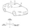
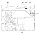
- FIG. 1is a view showing an appearance of a vehicle according to an embodiment of the present invention.
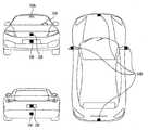
- FIG. 2is a view of a vehicle according to an embodiment of the present invention viewed from various angles.
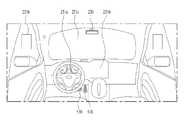
- 3 to 4are views showing an interior of a vehicle according to an embodiment of the present invention.
- FIG. 7is a block diagram of a vehicle according to an embodiment of the present invention.
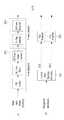
- FIG. 8illustrates a structure of a broadcast signal transmitting apparatus for a next generation broadcast service according to an embodiment of the present invention.
- Figure 9shows an Input formatting block according to an embodiment of the present invention.
- FIG. 10illustrates a bit interleaved coding & modulation (BICM) block according to an embodiment of the present invention.
- BICMbit interleaved coding & modulation
- FIG. 11shows a BICM block according to another embodiment of the present invention.
- FIG. 12shows a frame building block according to an embodiment of the present invention.
- FIG 13shows an orthogonal frequency division multiplexing (OFDM) generation block according to an embodiment of the present invention.
- FIG. 14shows a structure of a broadcasting signal receiving apparatus for a next generation broadcasting service according to an embodiment of the present invention.
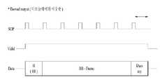
- FIG. 15shows a frame structure according to an embodiment of the present invention.
- FIG. 16shows a signaling hierarchical structure of a frame according to an embodiment of the present invention.
- FIG 17shows PLS1 data according to an embodiment of the present invention.
- FIG 19shows PLS2 data according to another embodiment of the present invention.
- FIG. 20shows a logical and logical structure of a frame according to an embodiment of the present invention.
- Fig. 21shows a configuration of a vehicle according to an embodiment of the present invention.
- FIG. 22shows a configuration of a receiving apparatus for a vehicle according to an embodiment of the present invention.
- FIG. 23shows an encoder and a processor of a vehicle reception apparatus according to an embodiment of the present invention.
- FIG. 24shows a process of processing data between an encoder and a processor of a receiver for a vehicle according to an embodiment of the present invention.
- 25shows a process of receiving data by an encoder of a receiving apparatus for a vehicle according to an embodiment of the present invention.
- 26shows a process of controlling data by an encoder of a vehicle reception apparatus according to an embodiment of the present invention.
- FIG. 27shows a buffer control process according to an embodiment of the present invention.
- FIG. 28shows a process of acquiring a BB frame size according to an embodiment of the present invention.
- the vehicle described hereinmay be a concept including a car, a motorcycle.
- the vehiclewill be described mainly with respect to the vehicle.
- the vehicle described in the present specificationmay be a concept including both an internal combustion engine vehicle having an engine as a power source, a hybrid vehicle having an engine and an electric motor as a power source, and an electric vehicle having an electric motor as a power source.
- the left side of the vehiclemeans the left side in the running direction of the vehicle
- the right side of the vehiclemeans the right side in the running direction of the vehicle
- FIG. 1is a view showing an appearance of a vehicle according to an embodiment of the present invention.
- FIG. 2is a view of a vehicle according to an embodiment of the present invention viewed from various angles.
- 3 to 4are views showing an interior of a vehicle according to an embodiment of the present invention.
- FIG. 7is a block diagram of a vehicle according to an embodiment of the present invention.
- the vehicle 100may include a wheel rotated by a power source, and a steering input device 510 for adjusting the traveling direction of the vehicle 100.
- the vehicle 100may be an autonomous vehicle.
- the vehicle 100can be switched to the autonomous running mode or the manual mode based on the user input.
- the vehicle 100can be switched from the manual mode to the autonomous mode, or switched from the autonomous mode to the manual mode, based on the received user input, via the user interface device 200.
- the vehicle 100can be switched to the autonomous running mode or the manual mode based on the running situation information.
- the running situation informationmay include at least one of object information outside the vehicle, navigation information, and vehicle condition information.
- the vehicle 100can be switched from the manual mode to the autonomous mode or switched from the autonomous mode to the manual mode based on the running condition information generated by the object detection device 300.
- the vehicle 100can be switched from the manual mode to the autonomous mode or switched from the autonomous mode to the manual mode based on the running condition information received via the communication device 400.
- the vehicle 100can be switched from the manual mode to the autonomous mode based on information, data and signals provided from the external device, or can be switched from the autonomous mode to the manual mode.
- the autonomous vehicle 100can be operated on the basis of the running system 700.
- the autonomous vehicle 100may be operated based on information, data, or signals generated in the traveling system 710, the outbound system 740, and the parking system 750.
- the autonomous vehicle 100can receive a user input for driving through the driving operation device 500. [ Based on the user input received through the driving operation device 500, the vehicle 100 can be operated.
- the overall lengthmeans the length from the front portion to the rear portion of the vehicle 100 and the width is the width of the vehicle 100 and the height means the length from the bottom of the wheel to the roof.
- the total length direction Lis a direction in which the full length direction of the vehicle 100 is measured
- the full width direction Wis a reference for the full width measurement of the vehicle 100, Which is a reference for the measurement of the height of the object 100.
- the vehicle 100includes a user interface device 200, an object detection device 300, a communication device 400, a driving operation device 500, a vehicle driving device 600, A navigation system 770, a sensing unit 120, an interface unit 130, a memory 140, a control unit 170, and a power supply unit 190.
- the vehicle 100may further include other components than the components described herein, or may not include some of the components to be described.
- the sensing unit 120may include a sensor such as a yaw sensor, a roll sensor, a pitch sensor, a collision sensor, a wheel sensor, a velocity sensor, A head sensor, a gyro sensor, a position module, a vehicle forward / backward sensor, a battery sensor, a fuel sensor, a tire sensor, a steering sensor by steering wheel rotation, a vehicle An internal temperature sensor, an in-vehicle humidity sensor, an ultrasonic sensor, an illuminance sensor, an accelerator pedal position sensor, a brake pedal position sensor, and the like.
- the sensing unit 120is configured to generate the sensing information based on the vehicle attitude information, the vehicle collision information, the vehicle direction information, the vehicle position information (GPS information), the vehicle angle information, the vehicle speed information, Obtain a sensing signal for information, fuel information, tire information, vehicle lamp information, vehicle interior temperature information, vehicle interior humidity information, steering wheel rotation angle, vehicle exterior illumination, pressure applied to the accelerator pedal, pressure applied to the brake pedal, can do.
- the sensing unit 120may further include an accelerator pedal sensor, a pressure sensor, an engine speed sensor, an air flow sensor AFS, an intake air temperature sensor ATS, a water temperature sensor WTS, (TPS), a TDC sensor, a crank angle sensor (CAS), and the like.
- the sensing unit 120can generate vehicle state information based on the sensing data.
- the vehicle status informationmay be information generated based on data sensed by various sensors provided in the vehicle.
- the vehicle state informationincludes at least one of attitude information of the vehicle, speed information of the vehicle, tilt information of the vehicle, weight information of the vehicle, direction information of the vehicle, battery information of the vehicle, fuel information of the vehicle, Vehicle steering information, vehicle interior temperature information, vehicle interior humidity information, pedal position information, and vehicle engine temperature information.
- the interface unit 130may serve as a pathway to various kinds of external devices connected to the vehicle 100.
- the interface unit 130may include a port that can be connected to the mobile terminal, and may be connected to the mobile terminal through the port. In this case, the interface unit 130 can exchange data with the mobile terminal.
- the interface unit 130may serve as a channel for supplying electrical energy to the connected mobile terminal.
- the interface unit 130may provide the mobile terminal with electric energy supplied from the power supply unit 190 under the control of the controller 170.
- the memory 140is electrically connected to the control unit 170.
- the memory 140may store basic data for the unit, control data for controlling the operation of the unit, and input / output data.
- the memory 140may be, in hardware, various storage devices such as ROM, RAM, EPROM, flash drive, hard drive, and the like.
- the memory 140may store various data for operation of the vehicle 100, such as a program for processing or controlling the controller 170.
- the memory 140may be formed integrally with the controller 170 or may be implemented as a subcomponent of the controller 170.
- the control unit 170can control the overall operation of each unit in the vehicle 100.
- the control unit 170may be called an ECU (Electronic Control Unit).
- the power supply unit 190can supply power necessary for the operation of each component under the control of the control unit 170. Particularly, the power supply unit 190 can receive power from a battery or the like inside the vehicle.
- processors and controls 170 included in vehicle 100may be implemented as application specific integrated circuits (ASICs), digital signal processors (DSPs), digital signal processing devices (DSPDs), programmable logic devices (PLDs) field programmable gate arrays, processors, controllers, micro-controllers, microprocessors, and other electrical units for performing other functions.
- ASICsapplication specific integrated circuits
- DSPsdigital signal processors
- DSPDsdigital signal processing devices
- PLDsprogrammable logic devices field programmable gate arrays
- processorscontrollers, micro-controllers, microprocessors, and other electrical units for performing other functions.
- the vehicle drive system 600, the operating system 700 and the navigation system 770may have separate processors or may be integrated into the controller 170.
- the user interface device 200is a device for communicating between the vehicle 100 and a user.
- the user interface device 200may receive user input and provide information generated by the vehicle 100 to the user.
- the vehicle 100can implement UI (User Interfaces) or UX (User Experience) through the user interface device 200.
- UIUser Interfaces
- UXUser Experience
- the user interface device 200may include an input unit 210, an internal camera 220, a biological sensing unit 230, an output unit 250, and a processor 270. Each component of the user interface device 200 can be structurally and functionally separated or integrated with the interface 130 described above.
- the user interface device 200may further include other components than the components described, or may not include some of the components described.
- the input unit 210is for receiving information from a user.
- the data collected by the input unit 210may be analyzed by the processor 270 and processed by a user's control command.
- the input unit 210may be disposed inside the vehicle.
- the input unit 210may include one area of a steering wheel, one area of an instrument panel, one area of a seat, one area of each pillar, one area of the head console, one area of the door, one area of the center console, one area of the head lining, one area of the sun visor, one area of the windshield, One area or the like.
- the input unit 210may include a voice input unit 211, a gesture input unit 212, a touch input unit 213, and a mechanical input unit 214.
- the voice input unit 211can switch the voice input of the user into an electrical signal.
- the converted electrical signalmay be provided to the processor 270 or the control unit 170.
- the voice input unit 211may include one or more microphones.
- the gesture input unit 212can switch the user's gesture input to an electrical signal.
- the converted electrical signalmay be provided to the processor 270 or the control unit 170.
- the gesture input unit 212may include at least one of an infrared sensor and an image sensor for detecting a user's gesture input.
- the gesture input 212may sense a user's three-dimensional gesture input.
- the gesture input unit 212may include an optical output unit for outputting a plurality of infrared rays or a plurality of image sensors.
- the gesture input unit 212can sense a user's three-dimensional gesture input through a time of flight (TOF) method, a structured light method, or a disparity method.
- TOFtime of flight
- the touch input unit 213can switch the touch input of the user into an electrical signal.
- the converted electrical signalmay be provided to the processor 270 or the controller 170.
- the touch input unit 213may include a touch sensor for sensing a touch input of a user.
- the touch input unit 213is integrated with the display unit 251, thereby realizing a touch screen.
- a touch screenmay provide an input interface and an output interface between the vehicle 100 and a user.
- the mechanical input unit 214may include at least one of a button, a dome switch, a jog wheel, and a jog switch.
- the electrical signal generated by the mechanical input 214may be provided to the processor 270 or the controller 170.
- the mechanical input 214may be disposed on a steering wheel, a center fascia, a center console, a cockpit module, a door, or the like.
- the processor 270initiates the learning mode of the vehicle 100 in response to user input to at least one of the voice input unit 211, the gesture input unit 212, the touch input unit 213 and the mechanical input unit 214 described above. can do.
- the vehicle 100can perform the traveling path learning of the vehicle and the surrounding environment learning.
- the learning modewill be described in detail below with respect to the object detecting apparatus 300 and the operating system 700.
- the internal camera 220can acquire the in-vehicle image.
- the processor 270can sense the state of the user based on the in-vehicle image.
- the processor 270can obtain the user's gaze information from the in-vehicle image.
- the processor 270may sense the user's gesture in the in-vehicle video.
- the biometric sensor 230can acquire biometric information of the user.
- the biometric sensor 230includes a sensor capable of acquiring biometric information of a user, and can acquire fingerprint information, heartbeat information, etc. of a user using a sensor. Biometric information can be used for user authentication.
- the output unit 250is for generating an output related to a visual, auditory or tactile sense or the like.
- the output unit 250may include at least one of a display unit 251, an acoustic output unit 252, and a haptic output unit 253.
- the display unit 251may display graphic objects corresponding to various information.
- the display unit 251may be a liquid crystal display (LCD), a thin film transistor-liquid crystal display (TFT LCD), an organic light-emitting diode (OLED) display, a 3D display, and an e-ink display.
- LCDliquid crystal display
- TFT LCDthin film transistor-liquid crystal display
- OLEDorganic light-emitting diode
- the display unit 251may have a mutual layer structure with the touch input unit 213 or may be integrally formed to realize a touch screen.
- the display unit 251may be implemented as a Head Up Display (HUD).
- HUDHead Up Display
- the display unit 251may include a projection module to output information through an image projected on a windshield or a window.
- the display unit 251may include a transparent display.
- the transparent displaymay be attached to the windshield or window.
- the transparent displaycan display a predetermined screen while having a predetermined transparency.
- Transparent displayscan be used to have transparency, transparent displays include transparent TFEL (Thin Film Electroluminescent), transparent OLED (Organic Light-Emitting Diode), transparent LCD (Liquid Crystal Display), transmissive transparent display, Or the like. The transparency of the transparent display can be adjusted.
- the user interface device 200may include a plurality of display units 251a to 251g.
- the display unit 251includes one region of the steering wheel, one region 251a, 251b and 251e of the inspiration panel, one region 251d of the sheet, one region 251f of each filler, 251g), one area of the center console, one area of the head lining, one area of the sun visor, one area 251c of the windshield, and one area 251h of the window.
- the audio output unit 252converts an electric signal provided from the processor 270 or the control unit 170 into an audio signal and outputs the audio signal.
- the sound output section 252may include one or more speakers.
- the haptic output unit 253generates a tactile output.
- the haptic output section 253may operate to vibrate the steering wheel, the seat belt, the seat 110FL, 110FR, 110RL, and 110RR so that the user can recognize the output.
- the processor 270may control the overall operation of each unit of the user interface device 200.
- the user interface device 200may include a plurality of processors 270, or may not include a processor 270.
- the user interface device 200may be operated under the control of the processor or the control unit 170 of another apparatus in the vehicle 100.
- the user interface device 200may be referred to as a vehicle display device.
- the user interface device 200may be operated under the control of the control unit 170.
- the object detecting apparatus 300is an apparatus for detecting an object located outside the vehicle 100. [ The object detecting apparatus 300 can generate object information based on the sensing data.
- the object informationmay include information on the presence or absence of the object, position information of the object, distance information between the vehicle 100 and the object, and relative speed information between the vehicle 100 and the object.
- the objectmay be various objects related to the operation of the vehicle 100.
- an object Ois a vehicle that is a vehicle that has a lane OB10, another vehicle OB11, a pedestrian OB12, a two-wheeled vehicle OB13, traffic signals OB14 and OB15, Speed bumps, terrain, animals, and the like.
- the lane OB10may be a driving lane, a side lane of the driving lane, or a lane on which the opposed vehicle runs.
- the lane OB10may be a concept including left and right lines Line forming a lane.
- the other vehicle OB11may be a vehicle running in the vicinity of the vehicle 100.
- the other vehiclemay be a vehicle located within a predetermined distance from the vehicle 100.
- the other vehicle OB11may be a vehicle preceding or following the vehicle 100.
- the pedestrian OB12may be a person located in the vicinity of the vehicle 100. [ The pedestrian OB12 may be a person located within a predetermined distance from the vehicle 100. [ For example, the pedestrian OB12 may be a person who is located on the delivery or driveway.
- the two-wheeled vehicle OB13may mean a vehicle located around the vehicle 100 and moving using two wheels.
- the two-wheeled vehicle OB13may be a rider having two wheels positioned within a predetermined distance from the vehicle 100.
- the two-wheeled vehicle OB13may be a motorcycle or a bicycle located on a sidewalk or a motorway.
- the traffic signalmay include a traffic light (OB15), a traffic sign (OB14), a pattern drawn on the road surface, or text.
- the lightmay be light generated from lamps provided in other vehicles.
- Lightcan be light generated from a street light.
- Lightcan be solar light.
- the roadmay include a slope such as a road surface, a curve, an uphill, a downhill, and the like.
- the structuremay be an object located around the road and fixed to the ground.
- the structuremay include street lamps, street lamps, buildings, electric poles, traffic lights, and bridges.
- the terrainmay include mountains, hills, and the like.
- an objectcan be classified into a moving object and a fixed object.
- the moving objectmay be a concept including an other vehicle, a pedestrian.
- the fixed objectmay be a concept including a traffic signal, a road, and a structure.
- the object detection apparatus 300may include a camera 310, a radar 320, a LR 330, an ultrasonic sensor 340, an infrared sensor 350, and a processor 370. Each component of the object detecting apparatus 300 can be structurally and functionally separated or integrated with the sensing unit 120 described above.
- the object detecting apparatus 300may further include other elements other than the described elements, or may not include some of the described elements.
- the camera 310may be located at an appropriate location outside the vehicle to obtain the vehicle exterior image.
- the camera 310may be a mono camera, a stereo camera 310a, an AVM (Around View Monitoring) camera 310b, or a 360 degree camera.
- the camera 310can acquire the position information of the object, the distance information to the object, or the relative speed information with the object using various image processing algorithms.
- the camera 310can acquire distance information and relative velocity information with respect to the object based on a change in the object size with time in the acquired image.
- the camera 310can acquire distance information and relative speed information with respect to the object through a pin hole model, a road surface profiling, and the like.
- the camera 310may acquire distance information and relative speed information with respect to the object based on disparity information in the stereo image acquired by the stereo camera 310a.
- the camera 310may be disposed in the interior of the vehicle, close to the front windshield, to acquire an image of the front of the vehicle.
- the camera 310may be disposed around a front bumper or radiator grill.
- the camera 310can be disposed in the interior of the vehicle, close to the rear glass, to acquire images of the rear of the vehicle.
- the camera 310may be disposed around a rear bumper, trunk, or tailgate.
- the camera 310may be disposed close to at least one of the side windows in the interior of the vehicle to obtain the image of the side of the vehicle.
- the camera 310may be disposed around a side mirror, fender, or door.
- the camera 310may provide the acquired image to the processor 370.
- the radar 320may include an electromagnetic wave transmitting unit and a receiving unit.
- the radar 320may be implemented by a pulse radar system or a continuous wave radar system in terms of the radio wave emission principle.
- the radar 320may be implemented by a frequency modulated continuous wave (FMCW) scheme or a frequency shift keying (FSK) scheme according to a signal waveform in a continuous wave radar scheme.
- FMCWfrequency modulated continuous wave
- FSKfrequency shift keying
- the radar 320detects an object based on a time-of-flight (TOF) method or a phase-shift method through an electromagnetic wave, and detects the position of the detected object, the distance to the detected object, Can be detected.
- TOFtime-of-flight
- phase-shift methodthrough an electromagnetic wave
- the radar 320may be placed at a suitable location outside the vehicle to sense objects located at the front, rear, or side of the vehicle.
- the ladder 330may include a laser transmitting unit and a receiving unit.
- the LIDAR 330may be implemented in a time of flight (TOF) scheme or a phase-shift scheme.
- the lidar 330may be implemented as a drive or an unshifted drive.
- the LIDAR 330When implemented in a driving manner, the LIDAR 330 is rotated by a motor and can detect an object in the vicinity of the vehicle 100.
- the LIDAR 330can detect an object located within a predetermined range with respect to the vehicle 100 by optical steering.
- the vehicle 100may include a plurality of non-driven RRs 330.
- the lidar 330detects an object based on a laser light medium, a time of flight (TOF) method, or a phase-shift method, and detects the position of the detected object, The relative speed can be detected.
- TOFtime of flight
- the lidar 330may be disposed at an appropriate location outside the vehicle to sense objects located at the front, rear, or side of the vehicle.
- the ultrasonic sensor 340may include an ultrasonic transmitter and a receiver.
- the ultrasonic sensor 340can detect the object based on the ultrasonic wave, and can detect the position of the detected object, the distance to the detected object, and the relative speed.
- the ultrasonic sensor 340may be disposed at an appropriate position outside the vehicle for sensing an object located at the front, rear, or side of the vehicle.
- the infrared sensor 350may include an infrared ray transmitter and a receiver.
- the infrared sensor 340can detect the object based on the infrared light, and can detect the position of the detected object, the distance to the detected object, and the relative speed.
- the infrared sensor 350may be disposed at an appropriate position outside the vehicle for sensing an object located at the front, rear, or side of the vehicle.
- the processor 370can control the overall operation of each unit of the object detecting apparatus 300.
- the processor 370compares the data sensed by the camera 310, the radar 320, the lidar 330, the ultrasonic sensor 340, and the infrared sensor 350 with the stored data to detect or classify the object can do.
- the processor 370can detect and track the object based on the acquired image.
- the processor 370can perform operations such as calculating a distance to an object, calculating a relative speed with respect to the object, and the like through an image processing algorithm.
- the processor 370can obtain distance information and relative speed information with respect to the object, based on a change in the object size with time, in the acquired image.
- the processor 370can acquire distance information and relative speed information with respect to the object through a pin hole model, a road surface profiling, and the like.
- the processor 370may acquire distance information and relative speed information with respect to the object based on disparity information in the stereo image acquired by the stereo camera 310a.
- the processor 370can detect and track the object based on the reflected electromagnetic waves that are reflected from the object by the transmitted electromagnetic waves.
- the processor 370can perform operations such as calculating a distance to an object and calculating a relative speed with respect to the object based on electromagnetic waves.
- the processor 370can detect and track the object based on the reflected laser light reflected back from the object by the transmitted laser. Based on the laser light, the processor 370 can perform operations such as calculating the distance to the object and calculating the relative speed with respect to the object.
- the processor 370can detect and track the object on the basis of the reflected ultrasonic waves reflected by the object and transmitted back.
- the processor 370can perform operations such as calculating the distance to the object and calculating the relative speed with respect to the object based on the ultrasonic waves.
- the processor 370can detect and track the object based on the reflected infrared light that the transmitted infrared light reflects back to the object.
- the processor 370can perform operations such as calculating the distance to the object and calculating the relative speed with respect to the object based on the infrared light.
- the processor 370may include a camera 310, a radar 320, And the data sensed by the infrared sensor 350 and the infrared sensor 350 may be stored in the memory 140.
- the object detecting apparatus 300may include a plurality of processors 370 or may not include the processor 370.
- each of the camera 310, the radar 320, the RI 330, the ultrasonic sensor 340, and the infrared sensor 350may individually include a processor.
- the object detecting apparatus 300can be operated under the control of the processor of the apparatus in the vehicle 100 or the controller 170 when the object detecting apparatus 300 does not include the processor 370.
- the object detecting apparatus 300can be operated under the control of the control section 170.
- the communication device 400is a device for performing communication with an external device.
- the external devicemay be another vehicle, a mobile terminal, or a server.
- the communication device 400may include at least one of a transmission antenna, a reception antenna, an RF (Radio Frequency) circuit capable of implementing various communication protocols, and an RF device to perform communication.
- RFRadio Frequency
- the communication device 400includes a local communication unit 410, a location information unit 420, a V2X communication unit 430, an optical communication unit 440, a broadcast transmission / reception unit 450, an ITS (Intelligent Transport Systems) communication unit 460, (470).
- a local communication unit 410a location information unit 420, a V2X communication unit 430, an optical communication unit 440, a broadcast transmission / reception unit 450, an ITS (Intelligent Transport Systems) communication unit 460, (470).
- ITSIntelligent Transport Systems
- the communication device 400may further include other components than the components described, or may not include some of the components described.
- the short-range communication unit 410is a unit for short-range communication.
- the short-range communication unit 410may be a wireless communication unit such as Bluetooth TM, Radio Frequency Identification (RFID), Infrared Data Association (IrDA), Ultra Wideband (UWB), ZigBee, Near Field Communication (NFC) -Fidelity), Wi-Fi Direct, and Wireless USB (Wireless Universal Serial Bus) technology.
- RFIDRadio Frequency Identification
- IrDAInfrared Data Association
- UWBUltra Wideband
- ZigBeeZigBee
- NFCNear Field Communication
- Wi-Fi DirectWireless USB (Wireless Universal Serial Bus) technology.
- the short-range communication unit 410may form short-range wireless communication networks to perform short-range communication between the vehicle 100 and at least one external device.
- the position information section 420is a unit for acquiring the position information of the vehicle 100.
- the location information unit 420may include a Global Positioning System (GPS) module or a Differential Global Positioning System (DGPS) module.
- GPSGlobal Positioning System
- DGPSDifferential Global Positioning System
- the V2X communication unit 430is a unit for performing wireless communication with a server (V2I: Vehicle to Infra), another vehicle (V2V: Vehicle to Vehicle), or a pedestrian (V2P: Vehicle to Pedestrian).
- the V2X communication unit 430may include an RF circuit capable of implementing communication with the infrastructure (V2I), inter-vehicle communication (V2V), and communication with the pedestrian (V2P) protocol.
- the optical communication unit 440is a unit for performing communication with an external device via light.
- the optical communication unit 440may include a light emitting unit that converts an electric signal into an optical signal and transmits it to the outside, and a light receiving unit that converts the received optical signal into an electric signal.
- the light emitting portionmay be formed so as to be integrated with the lamp included in the vehicle 100.
- the broadcast transmission / reception unit 450is a unit for receiving a broadcast signal from an external broadcast management server through a broadcast channel or transmitting a broadcast signal to a broadcast management server.
- the broadcast channelmay include a satellite channel and a terrestrial channel.
- the broadcast signalmay include a TV broadcast signal, a radio broadcast signal, and a data broadcast signal.
- the ITS communication unit 460can exchange information, data, or signals with the traffic system.
- the ITS communication unit 460can provide information and data acquired in the traffic system.
- the ITS communication unit 460can receive information, data or signals from the traffic system.
- the ITS communication unit 460can receive the road traffic information from the traffic system and provide it to the control unit 170.
- the ITS communication unit 460may receive a control signal from the traffic system and provide it to the control unit 170 or a processor provided in the vehicle 100.
- the processor 470can control the overall operation of each unit of the communication device 400.
- the communication device 400may include a plurality of processors 470 or may not include a processor 470.
- the communication device 400can be operated under the control of the processor or the control unit 170 of another apparatus in the vehicle 100.
- the communication device 400can implement the vehicle display device together with the user interface device 200.
- the vehicle display devicemay be called a telematics device or an AVN (Audio Video Navigation) device.
- the communication device 400may be operated under the control of the control unit 170.
- the driving operation device 500is a device for receiving a user input for operation.
- the vehicle 100can be operated on the basis of the signal provided by the driving operation device 500.
- the driving operation device 500may include a steering input device 510, an acceleration input device 530, and a brake input device 570.
- the steering input device 510may receive a forward direction input of the vehicle 100 from a user.
- the steering input device 510is preferably formed in a wheel shape so that steering input is possible by rotation.
- the steering input devicemay be formed as a touch screen, a touch pad, or a button.
- the acceleration input device 530may receive an input for acceleration of the vehicle 100 from a user.
- the brake input device 570can receive an input for deceleration of the vehicle 100 from the user.
- the acceleration input device 530 and the brake input device 570are preferably formed in a pedal shape.
- the acceleration input device or the brake input devicemay be formed as a touch screen, a touch pad, or a button.
- the driving operation device 500can be operated under the control of the control unit 170.
- the vehicle driving device 600is an apparatus for electrically controlling the driving of various devices in the vehicle 100.
- the vehicle driving apparatus 600includes a power train driving unit 610, a chassis driving unit 620, a door / window driving unit 630, a safety driving unit 640, a lamp driving unit 650 and an air conditioning driving unit 660 .
- the vehicle drive system 600may further include other elements other than the described elements, or may not include some of the elements described.
- the vehicle drive apparatus 600may include a processor. Each unit of the vehicle drive apparatus 600 may individually include a processor.
- the power train driving unit 610can control the operation of the power train apparatus.
- the power train driving unit 610may include a power source driving unit 611 and a transmission driving unit 612.
- the power source drive unit 611can perform control on the power source of the vehicle 100.
- the power source drive unit 610can perform electronic control of the engine.
- the output torque of the engine and the likecan be controlled.
- the power source drive unit 611can adjust the engine output torque under the control of the control unit 170.
- the power source driving unit 610can perform control on the motor.
- the power source drive unit 610can adjust the rotation speed, torque, and the like of the motor under the control of the control unit 170.
- the transmission drive unit 612can perform control on the transmission.
- the transmission drive unit 612can adjust the state of the transmission.
- the transmission drive unit 612can adjust the state of the transmission to forward (D), reverse (R), neutral (N), or parking (P).
- the transmission drive unit 612can adjust the gear engagement state in the forward (D) state.
- the chassis driving unit 620can control the operation of the chassis apparatus.
- the chassis driving unit 620may include a steering driving unit 621, a brake driving unit 622, and a suspension driving unit 623.
- the steering driver 621may perform electronic control of the steering apparatus in the vehicle 100. [ The steering driver 621 can change the traveling direction of the vehicle.
- the brake driver 622can perform electronic control of the brake apparatus in the vehicle 100. [ For example, it is possible to reduce the speed of the vehicle 100 by controlling the operation of the brakes disposed on the wheels.
- the brake driver 622can individually control each of the plurality of brakes.
- the brake driving unit 622can control the braking forces applied to the plurality of wheels to be different from each other.
- the suspension driving unit 623can perform electronic control on a suspension apparatus in the vehicle 100. [ For example, when there is a curvature on the road surface, the suspension driving unit 623 can control the suspension device so as to reduce the vibration of the vehicle 100. [
- the suspension driving unit 623can individually control each of the plurality of suspensions.
- the door / window driving unit 630may perform electronic control of a door apparatus or a window apparatus in the vehicle 100.
- the door / window driving unit 630may include a door driving unit 631 and a window driving unit 632.
- the door driving unit 631can control the door device.
- the door driving unit 631can control the opening and closing of a plurality of doors included in the vehicle 100. [
- the door driving unit 631can control the opening or closing of a trunk or a tail gate.
- the door driving unit 631can control the opening or closing of the sunroof.
- the window driving unit 632may perform an electronic control on a window apparatus. It is possible to control the opening or closing of the plurality of windows included in the vehicle 100.
- the safety device driving unit 640can perform electronic control of various safety apparatuses in the vehicle 100.
- the safety device driving unit 640may include an airbag driving unit 641, a seat belt driving unit 642, and a pedestrian protection device driving unit 643. [
- the airbag driver 641may perform electronic control of the airbag apparatus in the vehicle 100. [ For example, the airbag driver 641 can control the deployment of the airbag when a danger is detected.
- the seat belt driving unit 642can perform electronic control of the seatbelt apparatus in the vehicle 100.
- the seat belt driving portion 642can control the passenger to be fixed to the seats 110FL, 110FR, 110RL, and 110RR using the seat belt when a danger is detected.
- the pedestrian protection device driving section 643can perform electronic control on the hood lift and the pedestrian airbag.
- the pedestrian protection device driving section 643can control the hood lift-up and the pedestrian airbag deployment when a collision with a pedestrian is detected.
- the lamp driving unit 650can perform electronic control of various lamp apparatuses in the vehicle 100.
- the air conditioning driving unit 660can perform electronic control on the air conditioner in the vehicle 100. [ For example, when the temperature inside the vehicle is high, the air conditioning driving unit 660 can control the air conditioner to operate so that the cool air is supplied to the inside of the vehicle.
- the vehicle drive apparatus 600may include a processor. Each unit of the vehicle drive apparatus 600 may individually include a processor.
- the vehicle drive apparatus 600can be operated under the control of the control section 170.
- the operating system 700is a system for controlling various operations of the vehicle 100. [ The travel system 700 can be operated in the autonomous mode.
- the travel system 700may include a travel system 710, an outbound system 740, and a parking system 750.
- the travel system 700may further include other components than the components described, or may not include some of the components described.
- the travel system 700may include a processor.
- Each unit of the travel system 700may each include a processor individually.
- the driving system 700can control the running of the autonomous driving mode based on the learning.
- the learning mode and the operation mode based on completion of learningcan be performed.
- a method for the processor of the driving system 700 to perform a learning mode and an operating modewill be described below.
- the learning modecan be performed in the manual mode described above.
- the processor of the driving system 700can perform the traveling path learning of the vehicle 100 and the surrounding environment learning.
- the traveling route learningmay include generating map data on the route that the vehicle 100 travels.
- the processor of the navigation system 700can generate map data based on the information detected through the object detection apparatus 300 while the vehicle 100 travels from the origin to the destination.
- the surrounding environment learningmay include storing and analyzing information on the environment of the vehicle 100 during the driving process and the parking process of the vehicle 100.
- the processor of the driving system 700detects the information detected through the object detecting apparatus 300 in the parking process of the vehicle 100, for example, the position information of the parking space, the size information, the fixed (or non-fixed) Information on the surrounding environment of the vehicle 100 can be stored and analyzed based on information such as obstacle information and the like.
- the operation modecan be performed in the autonomous mode described above.
- the operation modewill be described on the assumption that the traveling route learning or the surrounding environment learning is completed through the learning mode.
- the operation modemay be performed in response to user input through the input unit 210, or may be performed automatically when the vehicle 100 reaches the driving route and the parking space where learning has been completed.
- the operation modeincludes a semi-autonomous operating mode requiring a part of the user's operation on the driving control device 500 and a fully-autonomous operation requiring no user's operation on the driving control device 500 Mode (fully autonomous operating mode).
- the processor of the driving system 700can control the driving system 710 in the operating mode to drive the vehicle 100 along the traveling path on which learning has been completed.
- the processor of the driving system 700can control the outgoing system 740 in the operating mode to leave the parked vehicle 100 from the learned parking space.
- the processor of the driving system 700can control the parking system 750 in the operation mode to park the vehicle 100 from the current position to the learned parking space.
- the driving system 700when the driving system 700 is implemented in software, it may be a sub-concept of the control unit 170.
- the operating system 700includes a user interface device 270, an object detecting device 300 and a communication device 400, a driving operation device 500, a vehicle driving device 600, a navigation system A sensing unit 770, a sensing unit 120, and a control unit 170.
- the traveling system 710can perform traveling of the vehicle 100.
- the navigation system 710can receive navigation information from the navigation system 770 and provide a control signal to the vehicle drive system 600 to perform the travel of the vehicle 100.
- the traveling system 710can receive the object information from the object detecting apparatus 300 and provide the vehicle driving apparatus 600 with a control signal to perform the traveling of the vehicle 100.
- the traveling system 710can receive the signal from the external device through the communication device 400 and provide a control signal to the vehicle driving device 600 to perform the traveling of the vehicle 100.
- the navigation system 710includes a user interface device 270, an object detection device 300 and a communication device 400, a driving operation device 500, a vehicle driving device 600, a navigation system 770, 120, and a control unit 170, and may be a system concept for performing driving of the vehicle 100.
- Such a traveling system 710may be referred to as a vehicle running control apparatus.
- the departure system 740can perform the departure of the vehicle 100.
- the outpost system 740can receive navigation information from the navigation system 770 and provide control signals to the vehicle driving apparatus 600 to perform the departure of the vehicle 100.
- the departure system 740can receive object information from the object detecting apparatus 300 and provide a control signal to the vehicle driving apparatus 600 to carry out the departure of the vehicle 100.
- the departure system 740can receive a signal from the external device via the communication device 400 and provide a control signal to the vehicle driving device 600 to perform the departure of the vehicle 100.
- the destination system 740includes a user interface device 270, an object detection device 300 and a communication device 400, a driving operation device 500, a vehicle driving device 600, a navigation system 770, 120 and a control unit 170.
- the control unit 170may be a system concept that carries out the departure of the vehicle 100.
- This outgoing system 740may be termed a vehicle outbound control device.
- the parking system 750can perform parking of the vehicle 100.
- the parking system 750may receive navigation information from the navigation system 770 and provide a control signal to the vehicle driving device 600 to perform parking of the vehicle 100.
- the parking system 750is capable of performing parking of the vehicle 100 by receiving object information from the object detecting apparatus 300 and providing a control signal to the vehicle driving apparatus 600.
- the parking system 750can receive the signal from the external device via the communication device 400 and provide a control signal to the vehicle driving device 600 to perform parking of the vehicle 100.
- the parking system 750includes a user interface device 270, an object detection device 300 and a communication device 400, a driving operation device 500, a vehicle driving device 600, a navigation system 770, 120 and a control unit 170.
- the system 100may be a system concept that carries out parking of the vehicle 100.
- Such a parking system 9750may be referred to as a vehicle parking control apparatus.
- the navigation system 770may provide navigation information.
- the navigation informationmay include at least one of map information, set destination information, route information according to the destination setting, information about various objects on the route, lane information, and current location information of the vehicle.
- the navigation system 770may include a memory, a processor.
- the memorycan store navigation information.
- the processormay control the operation of the navigation system 770.
- the navigation system 770can receive information from an external device via the communication device 400 and update the stored information.
- the navigation system 770may be classified as a subcomponent of the user interface device 200.
- the present inventionprovides an apparatus and method for transmitting and receiving broadcast signals for a next generation broadcast service.
- the next generation broadcasting serviceincludes a terrestrial broadcasting service, a mobile broadcasting service, and a UHDTV service.
- the present inventioncan process a broadcast signal for a next generation broadcast service through non-Multiple Input Multiple Output (MIMO) or MIMO scheme according to an embodiment.
- MIMOMultiple Input Multiple Output
- the non-MIMO scheme according to an embodiment of the present inventionmay include a multiple input single output (MISO) scheme, a single input single output (SISO) scheme, and the like.
- the MISO or MIMO schemeuses two antennas, but the present invention can be applied to a system using two or more antennas.
- the present inventionis capable of defining three PHY profiles (base, handheld, advanced profile) optimized to achieve the performance required for a particular application and to minimize receiver complexity. have.
- a physical profileis a subset of all the structures that a given receiver must implement.
- the three physical profilesshare most functional blocks, but differ slightly in certain blocks and / or parameters.
- a physical profilemay be further defined later.
- a future profilemay be multiplexed with a profile that resides on a single radio frequency (RF) channel via a future extension frame (FEF). Details of each physical profile will be described later.
- RFradio frequency
- FEFfuture extension frame
- the base profilerepresents the main use of a fixed receiver primarily connected to a roof-top antenna.
- the base profilemay include a portable device that can be moved to a location but belongs to a relatively stationary reception category.
- the use of the base profilecan be extended for handheld devices or vehicles by some improved implementation, but such use is not expected in base profile receiver operation.
- the target signal-to-noise ratio range of the receptionis approximately 10 to 20 dB, which includes the 15 dB signal-to-noise ratio reception capability of existing broadcast systems (e.g., ATSC A / 53).
- Receiver complexity and power consumptionare not as important as in battery-powered handheld devices that use handheld profiles. Important system parameters for the base profile are listed in Table 1 below.
- the handheld profileis designed for use in battery powered handheld and on-vehicle devices.
- the devicecan be moved at pedestrian or vehicle speed.
- Receiver complexity as well as power consumptionare very important for the implementation of handheld profile devices.
- the target signal-to-noise ratio range of the handheld profileis approximately 0-10 dB, but may be set to reach 0 dB below intended for lower indoor reception.
- the Advance Profileprovides higher channel capability in exchange for greater performance complexity.
- the profilerequires the use of MIMO transmission and reception, and the UHDTV service is targeted and the profile is specifically designed for this purpose.
- the enhanced capabilitycan also be used to allow for an increase in the number of services in a given bandwidth, for example, multiple SDTV or HDTV services.
- the target signal to noise ratio range of the Advance Profileis approximately 20 to 30 dB.
- the MIMO transmissioncan be initially extended by using a conventional elliptically polarized transmission device and then by a full output cross polarization transmission. Important system parameters for the Advance Profile are listed in Table 3 below.
- the base profilecan be used as a profile for both the terrestrial broadcast service and the mobile broadcast service. That is, the base profile can be used to define the concept of the profile including the mobile profile. Further, the advance profile can be divided into an advance profile for the base profile with MIMO and an advance profile for the handheld profile with MIMO. And the three profiles can be changed according to the designer's intention.
- Ancillary streamA sequence of cells carrying data of yet undefined modulation and coding that can be used as required by future extensions (or future extensions) or by broadcasters or network operators.
- Base data pipea data pipe that carries service signaling data
- Baseband frame(or BBFRAME): a set of Kbch bits that form the input for one FEC encoding process (BCH and LDPC encoding)
- Coded blockAn LDPC-encoded block of PLS1 data or one of LDPC-encoded blocks of PLS2 data
- Data pipea logical channel in a physical layer that carries service data or related metadata that can carry one or more services or service components
- Data pipe unita basic unit capable of assigning data cells to data pipes in a frame
- Data symbolan OFDM symbol (a frame signaling symbol and a frame edge symbol in a frame other than a preamble symbol is included in a data symbol).
- DP_IDThe corresponding 8-bit field uniquely identifies the data pipe within the system identified by SYSTEM_ID.
- Dummy cellA cell that carries a pseudorandom value that is used to fill the remaining unused capacity for physical layer signaling (PLS) signaling, datapipe, or auxiliary stream.
- PLSphysical layer signaling
- FACemergency alert channel
- Framea physical layer time slot that starts with a preamble and ends with a frame edge symbol
- Frame repetition unitA set of frames belonging to the same or different physical profile, including FEF, which is repeated eight times in the super-frame.
- FICfast information channel
- FECBLOCKset of LDPC encoded bits of data pipe data
- FFT sizeThe nominal FFT size used in the same specific mode as the active symbol period Ts expressed in cycles of the fundamental period T
- Frame signaling symbolThe higher pilot density used at the beginning of a frame in a particular combination of FFT size, guard interval, and scattered pilot pattern, which carries part of the PLS data, OFDM symbol
- Frame edge symbolan OFDM symbol with a higher pilot density used at the end of a frame in a particular combination of FFT size, guard interval, and scatter pilot pattern
- Frame-groupa set of all frames having the same physical profile type in a superframe
- Future Extension FrameA physical layer time slot within a superframe that can be used for future expansion, starting with a preamble.
- Futurecast UTB systemA proposed physical layer broadcast system in which the input is one or more MPEG2-TS or IP (Internet protocol) or generic stream and the output is an RF signal.
- Input streamA stream of data for ensembling services delivered to the end user by the system.
- Normal data symbolsdata symbols except frame signaling symbols and frame edge symbols
- PHY profileA subset of all the structures that the corresponding receiver must implement
- PLSPhysical layer signaling data composed of PLS1 and PLS2
- PLS1a first set of PLS data delivered in a frame signaling symbol (FSS) with a fixed size, coding, modulation to convey basic information about the system as well as the parameters needed to decode PLS2
- FSSframe signaling symbol
- PLS2a second set of PLS data transmitted to the FSS carrying more detailed PLS data about the datapipe and system
- PLS2 dynamic (dynamic) dataPLS2 data that changes dynamically per frame
- PLS2 static (static) dataStatic (static, static) PLS2 data during the duration of the frame group
- Preamble signaling dataSignaling data that is conveyed by the preamble symbol and used to identify the base mode of the system.
- Preamble symbolA pilot symbol that carries basic PLS data and has a fixed length at the beginning of the frame.
- Preamble symbolsare mainly used for high-speed initial band scans to detect system signals, timing, frequency offset, and FFT size.
- SuperframeA set of eight frame repeat units
- Time interleaving block(TI block): a set of cells in which time interleaving is performed, corresponding to one use of the time interleaver memory
- Time interleaving groupA unit in which dynamic, dynamic capacity allocation for a particular data pipe is performed, consisting of an integer, dynamic, and dynamic number of XFECBLOCKs.
- Time interleaving groupscan be mapped directly to one frame or to multiple frames.
- the time interleaving groupmay include one or more time interleaving blocks.
- Type 1 data pipe(Type 1 DP): A data pipe of a frame in which all data pipes are mapped in a time division multiplexing (TDM) manner to a frame
- Type 2 data pipes(Type 2 DP): Data pipes in frames where all data pipes are mapped in FDM fashion to frames
- XFECBLOCKa set of N cells cells carrying all bits of a LDPC FECBLOCK
- FIG. 8illustrates a structure of a broadcast signal transmitting apparatus for a next generation broadcast service according to an embodiment of the present invention.
- An apparatus for transmitting a broadcasting signal for a next generation broadcasting serviceincludes an input format block 1000, a bit interleaved coding and modulation (BICM) block 1010, a frame building block ) 1020, an orthogonal frequency division multiplexing (OFDM) generation block 1030, and a signaling generation block 1040. The operation of each block of the broadcast signal transmitting apparatus will be described.
- BICMbit interleaved coding and modulation
- OFDMorthogonal frequency division multiplexing
- IP streams / packets and MPEG2-TSare the main input formats, and other stream types are treated as normal streams.
- management informationis input to control the scheduling and allocation of the corresponding bandwidth for each input stream.
- One or more TS streams, IP streams, and / or generic stream inputsare allowed at the same time.
- the input format block 1000may demultiplex each input stream into one or more data pipes to which independent coding and modulation is applied.
- Datapipesare the basic unit for robustness control, which affects quality of service (QoS).
- QoSquality of service
- One or a plurality of services or service componentsmay be carried by one data pipe. The detailed operation of the input format block 1000 will be described later.
- a datapipeis a logical channel in the physical layer that conveys service data or related metadata that can carry one or more services or service components.
- the data pipe unitis also a basic unit for allocating data cells to data pipes in one frame.
- parity datais added for error correction and the encoded bit stream is mapped to a complex valued constellation symbol.
- the symbolsare interleaved over the specific interleaving depths used for that data pipe.
- MIMO encodingis performed in BICM block 1010 and additional data paths are added to the output for MIMO transmission. The detailed operation of the BICM block 1010 will be described later.
- the frame building block 1020may map the data cells of the input data pipe to the OFDM thread within one frame. After the mapping, frequency interleaving is used for frequency domain diversity, in particular to prevent frequency selective fading channels. The detailed operation of the frame building block 1020 will be described later.
- the OFDM generation block 1030may apply conventional OFDM modulation with a cyclic prefix as a guard interval.
- a distributed MISO schemeis applied across the transmitter.
- a peak-to-average power ratio (PAPR) schemeis performed in the time domain.
- PAPRpeak-to-average power ratio
- the proposalprovides a variety of FFT sizes, guard interval lengths, and a set of corresponding pilot patterns. The detailed operation of the OFDM generation block 1030 will be described later.
- the signaling generation block 1040may generate physical layer signaling information used for operation of each functional block.
- the signaling informationis also transmitted so that the service of interest is properly recovered at the receiver side. The detailed operation of the signaling generation block 1040 will be described later.
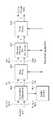
- 9shows an input format block according to an embodiment of the present invention. 9 shows an input format block when the input signal is a single input stream.
- the input format block shown in FIG. 9corresponds to one embodiment of the input format block 1000 described with reference to FIG.
- the input to the physical layermay consist of one or more data streams. Each data stream is carried by one data pipe.
- a mode adaptation moduleslices an input data stream into a data field of a BBF (baseband frame).
- the systemsupports three types of input data streams: MPEG2-TS, IP, and GS (generic stream).
- MPEG2-TSis characterized by a fixed length (188 bytes) packet whose first byte is a sync byte (0x47).
- An IP streamconsists of variable length IP datagram packets that are signaled within an IP packet header.
- the systemsupports both IPv4 and IPv6 for IP streams.
- the GSmay consist of a variable length packet or a constant length packet signaled within an encapsulation packet header.
- (a)shows a mode adaptation block 2000 and a stream adaptation 2010 for a signal data pipe
- (b)shows a block diagram for generating and processing PLS data PLS generation block 2020 and PLS scrambler 2030, respectively. The operation of each block will be described.
- An input stream splitterdivides input TS, IP, and GS streams into multiple service or service component (audio, video, etc.) streams.
- the mode adaptation module 2010comprises a CRC encoder, a BB (baseband) frame slicer, and a BB frame header insertion block.
- the CRC encoderprovides three CRC encodings for error detection at the user packet (UP) level: CRC-8, CRC-16, CRC-32.
- the calculated CRC byteis appended after the UP.
- CRC-8is used for the TS stream, and CRC-32 is used for the IP stream. If the GS stream does not provide CRC encoding, then the proposed CRC encoding should be applied.
- the BB frame slicermaps the input to the internal logical bit format.
- the first received bitis defined as MSB.
- the BB frame slicerallocates the same number of input bits as the available data field capacity. To allocate the same number of input bits as the BBF payload, the UP stream is sliced to fit the data field of the BBF.
- the BB frame header insertion blockmay insert a 2-byte fixed length BBF header in front of the BB frame.
- the BBF headerconsists of STUFFI (1 bit), SYNCD (13 bits), and RFU (2 bits).
- the BBFmay have an extension field (1 or 3 bytes) at the end of the 2-byte BBF header.
- a stream adaptation (stream adaptation) 2010comprises a stuffing insertion block and a BB scrambler.
- the stuffing insertion blockmay insert the stuffing field into the payload of the BB frame. If the input data for the stream adaptation is sufficient to fill the BB frame, STUFFI is set to zero and the BBF does not have the stuffing field. Otherwise, STUFFI is set to 1, and the stuffing field is inserted immediately after the BBF header.
- the stuffing fieldincludes a 2-byte stuffing field header and variable-size stuffing data.
- the BB scramblerscrambles the complete BBF for energy dissipation.
- the scrambling sequenceis synchronized with the BBF.
- the scrambling sequenceis generated by the feedback shift register.
- PLS generation block 2020may generate PLS data.
- the PLSprovides a means for the receiver to connect to the physical layer data pipe.
- the PLS datais composed of PLS1 data and PLS2 data.
- the PLS1 datais the first set of PLS data that is passed to the FSS in a frame with a fixed size, coding, modulation that conveys basic information about the system as well as the parameters needed to decode the PLS2 data.
- the PLS1 dataprovides basic transmission parameters that include the parameters required to enable reception and decoding of the PLS2 data. Further, the PLS1 data is constant during the duration of the frame group.
- the PLS2 datais a second set of PLS data transmitted to the FSS carrying more detailed PLS data about the data pipe and system.
- PLS2includes parameters that provide sufficient information for the receiver to decode the desired data pipe.
- PLS2 signalingis further comprised of two types of parameters: PLS2 static (static) data (PLS2-STAT data) and PLS2 dynamic (dynamic) data (PLS2-DYN data).
- PLS2 static (static, static) datais PLS2 data that is static (static) during the duration of a frame group
- PLS2 dynamic (dynamic) datais PLS2 data that changes dynamically per frame.
- the PLS scrambler 2030can scramble the generated PLS data for energy dispersion.
- FIG. 10shows a BICM block according to an embodiment of the present invention.
- the BICM block shown in FIG. 10corresponds to one embodiment of the BICM block 1010 described with reference to FIG.
- the broadcasting signal transmitting apparatus for the next generation broadcasting servicecan provide terrestrial broadcasting service, mobile broadcasting service, UHDTV service, and the like.
- the BICM block according to an embodiment of the present inventionindependently processes each data pipe by independently applying the SISO, MISO, and MIMO schemes to the data pipes corresponding to the respective data paths.
- the broadcast signal transmitting apparatus for the next generation broadcast service according to the embodiment of the present inventioncan adjust QoS for each service or service component transmitted through each data pipe.
- the BICM block shared by the base profile and handheld profile and the BICM block of the Advance Profilemay include a plurality of processing blocks for processing each data pipe.
- the processing block 5000 of the BICM block for the base profile and handheld profileincludes a data FEC encoder 5010, a bit interleaver 5020, a constellation mapper 5030, a signal space diversity (SSD) encoding block 5040, and a time interleaver 5050.
- the data FEC encoder 5010performs FEC encoding on the input BBF to generate the FECBLOCK procedure using outer coding (BCH) and inner coding (LDPC).
- BCHouter coding
- LDPCinner coding
- External coding (BCH)is an optional coding method. The concrete operation of the data FEC encoder 5010 will be described later.
- Bit interleaver 5020can achieve optimized performance with a combination of LDPC codes and modulation schemes by interleaving the output of data FEC encoder 5010 while providing a structure that can be efficiently implemented.
- the concrete operation of the bit interleaver 5020will be described later.
- the constellation mapper 5030may be a QPSK, a QAM-16, a non-uniform QAM (NUQ-64, NUQ-256, NUQ-1024), or a nonuniform constellation (NUC-16, NUC-64, NUC- ) To modulate each cell word from the bit interleaver 5020 in the base and handheld profiles or modulate the cell word from the cell word demultiplexer 5010-1 in the Advance Profile to generate a power normalized constellation point e l can offer.
- the corresponding constellation mappingapplies only to datapipes. While NUQ has a random shape, QAM-16 and NUQ have a square shape. As each constellation is rotated by a multiple of ninety degrees, the rotated constellation exactly overlaps with the original.
- NUQ and NUCare all specially defined for each code rate and the specific one used is signaled by the parameter DP_MOD stored in the PLS2 data.
- the SSD encoding block 5040can precode cells in two-dimensional, three-dimensional, and four-dimensional, thereby increasing the reception robustness in difficult fading conditions.
- the time interleaver 5050can operate at the data pipe level.
- the parameters of the time interleavingcan be set differently for each data pipe. The concrete operation of the time interleaver 5050 will be described later.
- the processing block 5000-1 of the BICM block for the Advance Profilemay include a data FEC encoder, a bit interleaver, a constellation mapper, and a time interleaver.
- processing block 5000-1is distinguished from processing block 5000 in that it further includes cell word demultiplexer 5010-1 and MIMO encoding block 5020-1.
- the operations of the data FEC encoder, bit interleaver, constellation mapper and time interleaver in the processing block 5000-1are the same as those of the data FEC encoder 5010, the bit interleaver 5020, the constellation mapper 5030, And the time interleaver 5050, the description thereof will be omitted.
- Cell word demultiplexer 5010-1is used to divide a data pipe of the Advance Profile into a single cell word stream into a double cell word stream for MIMO processing. Concrete operation of the cell word demultiplexer 5010-1 will be described later.
- the MIMO encoding block 5020-1may process the output of the cell word demultiplexer 5010-1 using a MIMO encoding scheme.
- the MIMO encoding schemeis optimized for broadcast signal transmission. MIMO technology is a promising way to achieve capacity increase, but it depends on channel characteristics. Particularly for broadcast, the difference in received signal power between the two antennas due to different signal propagation characteristics or the strong LOS component of the channel makes it difficult to obtain a capacity gain from MIMO.
- the proposed MIMO encoding schemeovercomes this problem using one phase randomization and rotation based precoding of the MIMO output signals.
- MIMO encodingis intended for a 2x2 MIMO system that requires at least two antennas at both the transmitter and the receiver.
- Two MIMO encoding modesare defined in the proposed full-rate spatial multiplexing (FR-SM) and full-rate full-diversity spatial multiplexing (FRFD-SM).
- FR-SMfull-rate spatial multiplexing
- FRFD-SMfull-rate full-diversity spatial multiplexing
- the FR-SM encodingprovides a capacity increase with relatively small complexity increases at the receiver side, while the FRFD-SM encoding provides increased capacity and additional diversity gain with increased complexity at the receiver side.
- the proposed MIMO encoding schemedoes not limit the antenna polarity placement.
- the MIMO processis required in the Advance Profile frame, which means that all data pipes in the Advance Profile frame are processed by the MIMO encoder.
- the MIMO processingis applied at the data pipe level.
- the pair of constellation mapper outputs NUQ(e 1, i And e2 , i ) are fed into the inputs of the MIMO encoder.
- the MIMO encoder output pair(g1, i and g2, i) is transmitted by the same carrier k and OFDM symbol l of each transmit antenna.
- FIG. 11shows a BICM block according to another embodiment of the present invention.
- the BICM block shown in FIG. 11corresponds to one embodiment of the BICM block 1010 described with reference to FIG.
- FIG 11shows a BICM block for protection of PLS, EAC, and FIC.
- the EACis a part of a frame that carries EAS information data
- the FICis a logical channel in a frame that carries mapping information between the service and the corresponding base data pipe. The EAC and FIC will be described in detail later.
- a BICM block for protection of PLS, EAC, and FICmay include a PLS FEC encoder 6000, a bit interleaver 6010, and a constellation mapper 6020.
- the PLS FEC encoder 6000may include a scrambler, a BCH encoding / zero insertion block, an LDPC encoding block, and an LDPC parity puncturing block. Each block of the BICM block will be described.
- the PLS FEC encoder 6000can encode scrambled PLS 1/2 data, EAC and FIC sections.
- the scramblermay scramble PLS1 data and PLS2 data before BCH encoding and shortening and punctured LDPC encoding.
- the BCH encoding / zero insertion blockmay perform outer encoding on the scrambled PLS 1/2 data using the shortened BCH code for PLS protection and insert a zero bit after BCH encoding. Only for PLS1 data, the output bit of the zero insertion can be permutated before LDPC encoding.
- the LDPC encoding blockmay encode the output of the BCH encoding / zero insertion block using LDPC codes.
- the C ldpc and the parity bits P ldpcare systematically encoded and appended from the PLS information block I ldpc with each zero inserted.
- the LDPC code parameters for PLS1 and PLS2are shown in Table 4 below.
- the LDPC parity puncturing blockmay perform puncturing on PLS1 data and PLS2 data.
- the bit interleaver 6010may interleave the respective shortening and punctured PLS1 data and PLS2 data.
- Constellation mapper 6020can map the bit interleaved PLS1 data and PLS2 data to the constellation.
- FIG. 12shows a frame building block according to an embodiment of the present invention.
- the frame building block shown in FIG. 12corresponds to an embodiment of the frame building block 1020 described with reference to FIG.
- the frame building blockmay include a delay compensation block 7000, a cell mapper 7010, and a frequency interleaver 7020. have. Each block of the frame building block will be described.
- the delay compensation block 7000adjusts the timing between the data pipe and the corresponding PLS data to ensure the co-time between the data pipe and the corresponding PLS data at the transmitter have.
- the PLS datais delayed by the data pipe.
- the delay of the BICM blockis mainly due to the time interleaver 5050.
- In-band signaling datamay cause information in the next time interleaving group to be delivered one frame ahead of the data pipe to be signaled.
- the delay compensation blockdelays the in-band signaling data accordingly.
- Cell mapper 7010may map the PLS, EAC, FIC, data pipe, auxiliary stream, and dummy cell to the active carrier of the OFDM symbol in the frame.
- the basic function of the cell mapper 7010is to transmit the data cells generated by time interleaving for each data pipe, PLS cell, and EAC / FIC cell, to the active cell corresponding to each OFDM symbol in one frame, to an active OFDM cell array.
- Service signaling data(such as program specific information (PSI) / SI) can be collected separately and sent by data pipes.
- PSIprogram specific information
- SIprogram specific information
- the frequency interleaver 7020may randomly interleave the data cells received by the cell mapper 7010 to provide frequency diversity.
- the frequency interleaver 7020may also operate on an OFDM symbol pair consisting of two sequential OFDM symbols using a different interleaving seed order to obtain the maximum interleaving gain in a single frame.
- FIG 13shows an OFDM generation block according to an embodiment of the present invention.
- the OFDM generation block shown in FIG. 13corresponds to one embodiment of the OFDM generation block 1030 described with reference to FIG.
- the OFDM generation blockmodulates an OFDM carrier by a cell generated by a frame building block, inserts a pilot, and generates a time-domain signal for transmission.
- the blocksequentially inserts a guard interval and applies PAPR reduction processing to generate a final RF signal.
- the OFDM generation blockincludes a pilot and reserved tone insertion block 8000, a 2D-eSFN (single frequency network) encoding block 8010, an inverse fast Fourier transform (IFFT) Block 8020, a PAPR reduction block 8030, a guard interval insertion block 8040, a preamble insertion block 8050, a system insertion block 8060, and a DAC block 8070).
- IFFTinverse fast Fourier transform
- the pilot and reserved tone insertion block 8000can insert pilot and reserved tone.
- the various cells in the OFDM symbolare modulated into reference information known as pilots with a transmitted value known a priori at the receiver.
- the information of the pilot cellis composed of a scattered pilot, a continuous pilot, an edge pilot, an FSS (frame signaling symbol) pilot, and a FES (frame edge symbol) pilot.
- Each pilotis transmitted at a specific increasing power level according to the pilot type and the pilot pattern.
- the value of the pilot informationis derived from a reference sequence corresponding to a set of values, one for each transmission carrier, in a given symbol.
- the pilotmay be used for frame synchronization, frequency synchronization, time synchronization, channel estimation, transmission mode identification, and may also be used to track phase noise.
- Reference information taken from the reference sequenceis transmitted in scattered pilot cells in all symbols except the preamble, FSS and FES of the frame.
- a continuous pilotis inserted into every symbol of a frame. The number and position of successive pilots depends both on the FFT size and on the scattered pilot pattern.
- the edge carriersare the same as the edge pilots in all symbols except the preamble symbol. Edge carriers are inserted to allow frequency interpolation to the edge of the spectrum.
- FSS pilotsare inserted into the FSS, and FES pilots are inserted into the FES.
- FSS pilots and FES pilotsare inserted to allow time interpolation to the edge of the frame.
- the system according to an embodiment of the present inventionsupports SFN in which a distributed MISO scheme is selectively used to support a very robust transmission mode.
- the 2D-eSFNis a distributed MISO scheme using multiple transmit antennas, and each antenna can be located in a different transmitter in the SFN network.
- the 2D-eSFN encoding block 8010may perform 2D-eSFN processing to generate time and frequency diversity in the SFN configuration to distort the phase of signals transmitted from multiple transmitters. Thus, burst errors due to low plane fading or deep fading for a long time can be alleviated.
- the IFFT block 8020can modulate the output from the 2D-eSFN encoding block 8010 using an OFDM modulation scheme. Every cell in a data symbol that is not designated as a pilot (or reserved tone) carries one of the data cells from the frequency interleaver. The cells are mapped to OFDM carriers.
- the PAPR reduction block 8030performs a PAPR reduction on the input signal using various PAPR reduction algorithms in the time domain.
- the guard interval insertion block 8040can insert a guard interval and the preamble insertion block 8050 can insert a preamble before the signal. Details of the structure of the preamble will be described later.
- the other system insertion block 8060multiplexes signals of a plurality of broadcast transmission / reception systems in the time domain so that data of two or more different broadcast transmission / reception systems providing broadcast services can be simultaneously transmitted in the same RF signal band .
- two or more different broadcast transmission / reception systemsrefer to systems providing different broadcast services.
- Different broadcasting servicesmay mean terrestrial broadcasting service, mobile broadcasting service, and the like. Data related to each broadcast service can be transmitted through different frames.
- the DAC block 8070can convert the input digital signal into an analog signal and output it.
- a signal output from the DAC block 8070may be transmitted through a plurality of output antennas according to a physical layer profile.
- the transmission antenna according to an exemplary embodiment of the present inventionmay have vertical or horizontal polarity.
- FIG. 14shows a structure of a broadcasting signal receiving apparatus for a next generation broadcasting service according to an embodiment of the present invention.
- the broadcast signal receiving apparatus for the next generation broadcast servicecan correspond to the broadcast signal transmitting apparatus for the next generation broadcast service described with reference to FIG.
- a broadcasting signal receiving apparatus for a next generation broadcasting serviceincludes a synchronization and demodulation module 9000, a frame parsing module 9010, a demapping and decoding module a demapping & decoding module 9020, an output processor 9030, and a signaling decoding module 9040. The operation of each module of the broadcast signal receiving apparatus will be described.
- the synchronization and demodulation module 9000receives the input signal through the m reception antennas, performs signal detection and synchronization with respect to the system corresponding to the broadcast signal reception apparatus, and performs a reverse process of the procedure executed by the broadcast signal transmission apparatus Can be performed.
- the frame parsing module 9010parses the input signal frame and can extract the data to which the service selected by the user is to be transmitted.
- the frame parsing module 9010can perform deinterleaving corresponding to the inverse process of interleaving.
- the position of the signal and the data to be extractedcan be obtained by decoding the data output from the signaling decoding module 9040, so that the scheduling information generated by the broadcast signal transmitting apparatus can be recovered.
- the demapping and decoding module 9020may convert the input signal into bit region data, and then deinterleave bit region data as needed.
- the demapping and decoding module 9020performs demapping on the mapping applied for transmission efficiency and can correct errors occurring in the transmission channel through decoding. In this case, the demapping and decoding module 9020 can obtain the transmission parameters necessary for demapping and decoding by decoding the data output from the signaling decoding module 9040.
- the output processor 9030may perform inverse processes of various compression / signal processing procedures applied by the broadcast signal transmitting apparatus to improve transmission efficiency. In this case, the output processor 9030 can obtain necessary control information from the data output from the signaling decoding module 9040.
- the output of the output processor 8300corresponds to a signal input to the broadcast signal transmitting apparatus, and may be an MPEG-TS, an IP stream (v4 or v6), and a GS.
- the signaling decoding module 9040may obtain PLS information from the signal demodulated by the synchronization and demodulation module 9000. As described above, the frame parsing module 9010, the demapping and decoding module 9200, and the output processor 9300 can execute the functions using the data output from the signaling decoding module 9040.
- FIG. 15shows a signaling hierarchy structure of a frame according to an embodiment of the present invention.
- preamble signaling data 11000PLS1 data 11010
- PLS2 data 11020The purpose of the preamble transmitted by the preamble signal every frame is to indicate the basic transmission parameter and transmission type of the frame.
- PLS1allows a receiver to connect to and decode PLS2 data containing parameters for connecting to a data pipe of interest.
- PLS2is transmitted every frame, and is divided into two main parts, PLS2-STAT data and PLS2-DYN data. The static (static) and dynamic (dynamic) portions of the PLS2 data are followed by padding if necessary.
- 16shows preamble signaling data according to an embodiment of the present invention.
- the preamble signaling dataconveys 21 bits of information necessary for the receiver to connect to the PLS data within the frame structure and track the data pipe. Details of the preamble signaling data are as follows.
- PHY_PROFILEThe corresponding 3-bit field indicates the physical profile type of the current frame.
- the mapping of the different physical profile typesis given in Table 5 below.
- FFT_SIZEThe corresponding 2-bit field indicates the FFT size of the current frame in the frame group as described in Table 6 below.
- GI_FRACTIONThe corresponding 3-bit field indicates the guard interval fraction value in the current superframe as described in Table 7 below.
- EAC_FLAGThe corresponding 1-bit field indicates whether the EAC is present in the current frame. If the field is set to 1, an EAS is provided in the current frame. If the field is set to 0, the EAS is not delivered in the current frame. The field can be switched dynamically within the superframe.
- PILOT_MODEThe corresponding 1-bit field indicates whether the pilot mode is the mobile mode or the fixed mode for the current frame in the current frame group. When the corresponding field is set to 0, the mobile pilot mode is used. When the corresponding field is set to 1, the fixed pilot mode is used.
- PAPR_FLAGThe corresponding 1-bit field indicates whether PAPR reduction is used for the current frame in the current frame group. If the corresponding field is set to 1, a tone reservation is used for PAPR reduction. If the corresponding field is set to 0, PAPR reduction is not used.
- the corresponding 3-bit fieldindicates the physical profile type configuration of FRUs present in the current superframe. In the corresponding fields in all preambles in the current superframe, all profile types conveyed in the current superframe are identified. The corresponding 3-bit field is defined differently for each profile as shown in Table 8 below.
- RESERVEDThe corresponding 7-bit field is reserved for future use.
- FIG 17shows PLS1 data according to an embodiment of the present invention.
- the PLS1 dataprovides basic transmission parameters including the parameters needed to enable reception and decoding of the PLS2. As described above, the PLS1 data does not change during the entire duration of one frame group.
- the specific definition of the signaling field of the PLS1 datais as follows.
- PREAMBLE_DATAThe corresponding 20-bit field is a copy of the preamble signaling data except for EAC_FLAG.
- NUM_FRAME_FRUThe corresponding 2-bit field indicates the number of frames per FRU.
- PAYLOAD_TYPEThe corresponding 3-bit field indicates the format of the payload data transmitted in the frame group. PAYLOAD_TYPE is signaled as shown in Table 9.
- NUM_FSSThe corresponding 2-bit field indicates the number of FSS in the current frame.
- SYSTEM_VERSIONThe corresponding 8-bit field indicates the version of the signal format to be transmitted. SYSTEM_VERSION is divided into two 4-bit fields, major version and minor version.
- MSB 4 bits of the SYSTEM_VERSION fieldindicate main version information. Changes in the major version field represent incompatible changes. The default value is 0000. For the version described in that standard, the value is set to 0000.
- Minor versionThe LSB of the SYSTEM_VERSION field, 4 bits, indicates the minor version information. Changes in the minor version field are compatible.
- CELL_IDThis is a 16-bit field that uniquely identifies the geographic cell in the ATSC network.
- the ATSC cell coveragemay be composed of more than one frequency depending on the number of frequencies used per futurecast UTB system. If the value of CELL_ID is unknown or unspecified, the corresponding field is set to zero.
- NETWORK_IDThis is a 16-bit field that uniquely identifies the current ATSC network.
- SYSTEM_IDThe corresponding 16-bit field uniquely identifies the future-cast UTB system within the ATSC network.
- the Futurecast UTB systemis a terrestrial broadcasting system in which the input is one or more input streams (TS, IP, GS) and the output is an RF signal.
- the Futurecast UTB systemdelivers FEF and one or more physical profiles if present.
- the same future-cast UTB systemallows different service streams to be transmitted and different RFs in different geographic areas, allowing local service insertion.
- the frame structure and schedulingare controlled in one place and are the same for all transmissions within the Futurecast UTB system.
- One or more future cast UTB systemsmay all have the same SYSTEM_ID meaning that they all have the same physical structure and configuration.
- the following loopsconsist of FRU_PHY_PROFILE, FRU_FRAME_LENGTH, FRU_GI_FRACTION, and RESERVED, which indicate the length and FRU configuration of each frame type.
- the loop sizeis fixed so that four physical profiles (including FEF) are signaled within the FRU. If NUM_FRAME_FRU is less than 4, unused fields are filled with zeros.
- FRU_PHY_PROFILEThe corresponding 3-bit field indicates the physical profile type of the (i + 1) th frame (i is the loop index) of the associated FRU.
- the corresponding fieldsuse the same signaling format as shown in Table 8.
- FRU_FRAME_LENGTHThe corresponding 2-bit field indicates the length of the (i + 1) th frame of the associated FRU.
- FRU_GI_FRACTIONThe corresponding 3-bit field indicates the guard interval part of the (i + 1) th frame of the associated FRU.
- FRU_GI_FRACTIONis signaled according to Table 7.
- RESERVEDThe corresponding 4-bit field is reserved for future use.
- the following fieldsprovide parameters for decoding PLS2 data.
- PLS2_FEC_TYPEThe corresponding 2-bit field indicates the type of FEC used by PLS2 protection.
- the FEC typeis signaled according to Table 10. Details of the LDPC codes will be described later.
- PLS2_MODThe corresponding 3-bit field indicates the modulation type used by PLS2.
- the modulation typeis signaled according to Table 11.
- PLS2_SIZE_CELLthe 15-bit field indicates the total C _partial_block the size (the cell number of a particular QAM) of all coded blocks for the PLS2 is passed from a current frame group. The value is constant over the entire duration of the current frame group.
- PLS2_STAT_SIZE_BITThe corresponding 14-bit field indicates the size of the PLS2-STAT for the current frame group as the number of bits. The value is constant over the entire duration of the current frame group.
- PLS2_DYN_SIZE_BITThe corresponding 14-bit field indicates the size of the PLS2-DYN for the current frame group in number of bits. The value is constant over the entire duration of the current frame group.
- PLS2_REP_FLAGThe corresponding 1-bit flag indicates whether the PLS2 repeat mode is used in the current frame group. If the value of the corresponding field is set to 1, the PLS2 repeat mode is activated. If the value of the corresponding field is set to 0, the PLS2 repeat mode is deactivated.
- PLS2_REP_SIZE_CELLthe 15-bit field indicates the total _partial_block C in case the repeat PLS2 used (the particular QAM cell number) size of the portion of the coded block PLS2 transmitted in every frame of a current frame group. If no iteration is used, the value of the field is equal to zero. The value is constant over the entire duration of the current frame group.
- PLS2_NEXT_FEC_TYPEThe corresponding 2-bit field indicates the FEC type used in the PLS2 delivered in each frame of the next frame group.
- the FEC typeis signaled according to Table 10.
- PLS2_NEXT_MODThe corresponding 3-bit field indicates the modulation type used in the PLS2 delivered in every frame of the next frame group.
- the modulation typeis signaled according to Table 11.
- PLS2_NEXT_REP_FLAGThe corresponding 1-bit flag indicates whether the PLS2 repeat mode is used in the next frame group. If the value of the corresponding field is set to 1, the PLS2 repeat mode is activated. If the value of the corresponding field is set to 0, the PLS2 repeat mode is deactivated.
- PLS2_NEXT_REP_SIZE_CELLthe 15-bit field indicates the total C _full_block the next frame group for the entire coded block PLS2 transmitted every frame of the size (the cell number of a particular QAM) when the PLS2 repeatedly used. If no repetition is used in the next frame group, the value of the corresponding field is equal to zero. The value is constant over the entire duration of the current frame group.
- PLS2_NEXT_REP_STAT_SIZE_BITThe corresponding 14-bit field indicates the size of the PLS2-STAT for the next frame group in the number of bits. The value is constant in the current frame group.
- PLS2_NEXT_REP_DYN_SIZE_BITThe corresponding 14-bit field indicates the size of the PLS2-DYN for the next frame group in the number of bits. The value is constant in the current frame group.
- PLS2_AP_MODEThe corresponding 2-bit field indicates whether additional parity is provided for PLS2 in the current frame group. The value is constant over the entire duration of the current frame group. Table 12 below provides values for the corresponding fields. If the value of the corresponding field is set to 00, no additional parity in the current frame group is used for PLS2.
- PLS2_AP_SIZE_CELLThe corresponding 15-bit field indicates the size of the additional parity bits of PLS2 (specified by the number of QAM cells). The value is constant over the entire duration of the current frame group.
- PLS2_NEXT_AP_MODEThe corresponding 2-bit field indicates whether additional parity is provided for PLS2 signaling every frame of the next frame group. The value is constant over the entire duration of the current frame group. Table 12 defines the values of the corresponding fields.
- PLS2_NEXT_AP_SIZE_CELLThe corresponding 15-bit field indicates the size (specified by the number of QAM cells) of additional parity bits of PLS2 every frame of the next frame group. The value is constant over the entire duration of the current frame group.
- RESERVEDThe corresponding 32-bit field is reserved for future use.
- the PLS2-STAT datais the same in the frame group, while the PLS2-DYN data provides specific information for the current frame.
- FIC_FLAGThe corresponding 1-bit field indicates whether FIC is used in the current frame group. If the value of the field is set to 1, FIC is provided in the current frame. If the value of this field is set to 0, FIC is not delivered in the current frame. The value is constant over the entire duration of the current frame group.
- AUX_FLAGThe corresponding 1-bit field indicates whether the auxiliary stream is used in the current frame group. If the value of the field is set to 1, then the auxiliary stream is provided in the current frame. If the value of the corresponding field is set to 0, the auxiliary frame is not transmitted in the current frame. The value is constant over the entire duration of the current frame group.
- NUM_DPThe corresponding 6-bit field indicates the number of data pipes delivered in the current frame. The value of the field is between 1 and 64, and the number of data pipes is NUM_DP + 1.
- DP_IDThe corresponding 6-bit field is uniquely identified in the physical profile.
- DP_TYPEThe corresponding 3-bit field indicates the type of data pipe. This is signaled according to Table 13 below.
- DP_GROUP_IDThe corresponding 8-bit field identifies the data pipe group to which the current data pipe is associated. This can be used to connect to the service component's data pipe associated with a particular service whose receiver will have the same DP_GROUP_ID.
- BASE_DP_IDThe corresponding 6-bit field indicates a data pipe that carries service signaling data (such as PSI / SI) used in the management layer.
- the data pipe indicated by BASE_DP_IDmay be a normal data pipe carrying service signaling data together with the service data or a dedicated data pipe carrying only service signaling data.
- DP_FEC_TYPEThe corresponding 2-bit field indicates the FEC type used by the associated datapipe.
- the FEC typeis signaled according to Table 14 below.
- DP_CODThe corresponding 4-bit field indicates the code rate used by the associated data pipe.
- the code rateis signaled according to Table 15 below.
- DP_MODThe corresponding 4-bit field indicates the modulation used by the associated data pipe.
- the modulationis signaled according to Table 16 below.
- DP_SSD_FLAGThe corresponding 1-bit field indicates whether the SSD mode is used in the associated data pipe. If the value of this field is set to 1, the SSD is used. If the value of this field is set to 0, the SSD is not used.
- DP_MIMOThe corresponding 3-bit field indicates what type of MIMO encoding process is applied to the associated data pipe.
- the type of MIMO encoding processis signaled according to Table 17 below.
- DP_TI_TYPEThe corresponding 1-bit field indicates the type of time interleaving. A value of 0 indicates that one time interleaving group corresponds to one frame and includes one or more time interleaving blocks. A value of 1 indicates that one time interleaving group is delivered in more than one frame and contains only one time interleaving block.
- DP_TI_LENGTHThe use of the corresponding 2-bit field (the allowed values are only 1, 2, 4, and 8) is determined by the value set in the following DP_TI_TYPE field.
- P Ithe number of frames to which each time interleaving group is mapped, and there is one time interleaving block per time interleaving group
- the values of P I allowed by the corresponding 2-bit fieldare defined in Table 18 below.
- DP_FRAME_INTERVALThe corresponding 2-bit field indicates the frame interval (I JUMP ) within the frame group for the associated datapipe, and the allowed values are 1, 2, 4, 8 (the corresponding 2-bit fields are 00, 01, 11). For datapipes that do not appear in every frame of a frame group, the value of that field is the same as the interval between successive frames. For example, if a datapipe appears in frames of 1, 5, 9, 13, etc., the value of that field is set to 4. For data pipes appearing in all frames, the value of that field is set to one.
- DP_TI_BYPASSThe corresponding 1-bit field determines the availability of the time interleaver 5050. If time interleaving is not used for the data pipe, the corresponding field value is set to one. On the other hand, if time interleaving is used, the corresponding field value is set to zero.
- DP_FIRST_FRAME_IDXThe corresponding 5-bit field indicates the index of the first frame of the superframe in which the current data pipe occurs.
- the value of DP_FIRST_FRAME_IDXis 0 to 31.
- DP_NUM_BLOCK_MAXThe corresponding 10-bit field indicates the maximum value of DP_NUM_BLOCKS for the corresponding data pipe. The value of this field has the same range as DP_NUM_BLOCKS.
- DP_PAYLOAD_TYPEThe corresponding 2-bit field indicates the type of payload data carried by a given data pipe. DP_PAYLOAD_TYPE is signaled according to Table 19 below.
- DP_INBAND_MODEThe corresponding 2-bit field indicates whether the current data pipe carries in-band signaling information.
- the in-band signaling typeis signaled according to Table 20 below.
- DP_PROTOCOL_TYPEThe corresponding 2-bit field indicates the protocol type of the payload delivered by the given data pipe.
- the protocol type of the payloadis signaled according to Table 21 below when the input payload type is selected.
- DP_CRC_MODEThe corresponding 2-bit field indicates whether CRC encoding is used in the input format block.
- the CRC modeis signaled according to Table 22 below.
- DNP_MODEThe corresponding 2-bit field indicates the null packet deletion mode used by the associated data pipe when DP_PAYLOAD_TYPE is set to TS ('00'). DNP_MODE is signaled according to Table 23 below. If DP_PAYLOAD_TYPE is not TS ('00'), DNP_MODE is set to a value of 00.
- ISSY_MODEThe corresponding 2-bit field indicates the ISSY mode used by the associated data pipe when DP_PAYLOAD_TYPE is set to TS ('00'). ISSY_MODE is signaled according to Table 24 below. If DP_PAYLOAD_TYPE is not TS ('00'), ISSY_MODE is set to a value of 00.
- HC_MODE_TSThe corresponding 2-bit field indicates the TS header compression mode used by the associated data pipe when DP_PAYLOAD_TYPE is set to TS ('00'). HC_MODE_TS is signaled according to Table 25 below.
- HC_MODE_IPThe corresponding 2-bit field indicates the IP header compression mode when DP_PAYLOAD_TYPE is set to IP ('01'). HC_MODE_IP is signaled according to Table 26 below.
- PIDThe corresponding 13-bit field indicates the number of PIDs for TS header compression when DP_PAYLOAD_TYPE is set to TS ('00') and HC_MODE_TS is set to 01 or 10.
- RESERVEDThe corresponding 8-bit field is reserved for future use.
- FIC_VERSIONThe corresponding 8-bit field indicates the version number of the FIC.
- FIC_LENGTH_BYTEThe corresponding 13-bit field indicates the length of the FIC in bytes.
- RESERVEDThe corresponding 8-bit field is reserved for future use.
- NUM_AUXThe corresponding 4-bit field indicates the number of auxiliary streams. Zero indicates that the auxiliary stream is not used.
- AUX_CONFIG_RFUThe corresponding 8-bit field is reserved for future use.
- AUX_STREAM_TYPEThe corresponding 4 bits are reserved for future use to indicate the type of the current auxiliary stream.
- AUX_PRIVATE_CONFIGThe corresponding 28-bit field is reserved for future use to signal the secondary stream.
- FIG. 19shows a logical structure of a frame according to an embodiment of the present invention.
- the PLS, EAC, FIC, data pipe, auxiliary stream, and dummy cellsare mapped to the active carrier of the OFDM symbol in the frame.
- PLS1 and PLS2are initially mapped to one or more FSSs. Thereafter, if there is an EAC, the EAC cell is mapped to the immediately following PLS field. The next time the FIC is present, the FIC cell is mapped.
- the data pipeis mapped after PLS, or after EAC or FIC if EAC or FIC is present.
- the Type 1 data pipeis mapped first, and the Type 2 data pipe is mapped next. The details of the type of the data pipe will be described later. In some cases, the datapipe may carry some special data or service signaling data to the EAS.
- the auxiliary stream or streamif present, is mapped next to the data pipe, which in turn is followed by a dummy cell.
- the above procedurethat is, PLS, EAC, FIC, data pipe, auxiliary stream, and dummy cell are all mapped together in order to accurately fill the cell capacity in the frame.
- FIG 20shows an FEC structure according to an embodiment of the present invention.
- the data FEC encodermay perform FEC encoding on the input BBF to generate the FECBLOCK procedure using outer coding (BCH) and inner coding (LDPC).
- BCHouter coding
- LDPCinner coding
- the FEC structure showncorresponds to FECBLOCK.
- the FEC BLOCK and FEC structureshave the same value corresponding to the length of the LDPC code word.
- N ldpc64800 bits (long FECBLOCK) or 16200 bits (short FECBLOCK).
- Tables 27 and 28 belowshow FEC encoding parameters for long FECBLOCK and short FECBLOCK, respectively.
- the 12-error correction BCH codeis used for external encoding of BBF.
- the BBF generator polynomial for short FECBLOCK and long FECBLOCKis obtained by multiplying all polynomials.
- the LDPC codeis used to encode the output of the outer BCH encoding.
- P ldpcParity bits
- I ldpcBCH-encoded BBF
- I ldpcI ldpc
- Equation (6)x represents the address of the parity bit accumulator corresponding to the information bit i 360 , i.e., the entry of the second row of the parity check matrix.
- the last parity bitis obtained as follows.
- the corresponding LDPC encoding procedure for the short FECBLOCKis similar to the LDPC encoding procedure for short FECBLOCK except that Table 29 is replaced by Table 30 and the address of the parity check matrix for the long FECBLOCK is replaced by the address of the parity check matrix for the short FECBLOCK. Encoding procedure.
- Fig. 21shows a configuration of a vehicle according to an embodiment of the present invention.
- a vehiclemay include an antenna 91000, a vehicle receiving apparatus 92000, and / or a head unit 93000.
- the antenna 91000can receive data.
- the datamay be broadcast signals including broadcast service data.
- the received broadcast signalmay conform to the Advanced Television System Committee (ATSC) broadcast standard.
- ATSCAdvanced Television System Committee
- the broadcast signal received by the antenna 91000is not limited to the ATSC broadcasting standard, but may conform to a broadcasting standard such as DVB (Digital Video Broadcasting).
- DVBDigital Video Broadcasting
- the antennamay be a smart antenna or the like.
- the vehicle-mounted receiving apparatus 92000receives data from the antenna 91000, encodes the received data, and transmits the encoded data to the head unit 93000.
- the vehicular receiver 92000may include all of the components in a form capable of serially transmitting data.
- the componentmay be referred to as a module or a unit or the like.
- the vehicle receiver 92000may transmit the received data using a component capable of data serial transmission, such as an Ethernet cable.
- the vehicular receiver 92000may include a receiver 103000, a demodulator 102000, an encoder 101000, and / or a processor 114000.
- the respective components of the vehicular receiverare described in detail in Figs. 22 to 27. Fig.
- the head unit 93000receives data from the on-vehicle receiving device 92000 and displays the data on the vehicle occupant or viewer.
- the components of the vehicle shown in Fig. 21can be included in the vehicle shown in Fig. 7 or can correspond to the respective components of the vehicle shown in Fig.
- FIG. 22shows a configuration of a receiving apparatus for a vehicle according to an embodiment of the present invention.
- a vehicle receiving apparatusmay include a receiver (Tuner, 103000), a demodulator (102000), and / or an encoder (101000).
- the receiver 103000receives the broadcast signal from the antenna 91000 and transmits the received data to the demodulator 102000.
- the data received by the receiveris broadcast service data conforming to a broadcasting standard such as ATSC or DVB.
- the receiver 103000may correspond to the synchronization and demodulation module 9000 of FIG. 14, and the synchronization and demodulation module 9000 has been described above with reference to FIG.
- the receiver 103000receives a broadcast signal including broadcast service data in the form of a signal frame.
- the receiver 103000can perform channel tuning in order to receive a broadcast signal.
- the receiver 103000performs channel tuning by setting a frequency for a broadcast signal. The specific channel tuning procedure of the receiver 103000 will be described later with reference to FIG.
- the demodulator 102000receives the data from which the signal detection and synchronization is performed from the receiver 103000 and demodulates the broadcast service data included in the data.
- the demodulator 102000may correspond to the frame parsing module 9010, demapping and decoding (bit deinterleaving) module 9020 of FIG. 14.
- the demodulator 102000receives data from which the signal detection and synchronization has been performed from the receiver 103000, performs frame parsing, demapping, and decoding to transmit data to the encoder 101000.
- the demodulator 102000receives the channel-tuned broadcast signal from the receiver 103000 and demodulates the data in the broadcast signal.
- a signal frame in a broadcast signal including broadcast service dataincludes transmission parameters for broadcast signal transmission.
- the signal framehas the structure of the signal frame described with reference to FIG. 15 and FIG.
- the transmission parametersmay correspond to the preamble described in FIG. 16 and PLS1 data (or L1 Basic signaling information) and PLS2 (or L1 Detail signaling information) described in FIGS. 17 to 18.
- the PLS1 data or PLS2 datamay be referred to as Layer 1 signaling information (or L1 signaling information).
- the demodulator 102000demodulates the data in the signal frame according to the transmission parameter, and outputs a BB (Baseband) frame including the broadcasting service data to the encoder 101000.
- BBBaseband
- the BB frame output to the encoder 101000is a baseband packet or a baseband frame in an FEC (Forward Error Correction) frame.
- FECForward Error Correction
- the demodulator 102000obtains configuration information about the BB frame and sends it to the encoder 101000 along with the BB frame.
- the setting information about the BB framemay include BB frame size information.
- the setting information regarding the BB framemay be referred to as a sideband signal or signaling information. The process for the demodulator 102000 to obtain the BB frame size information will be described later with reference to FIG.
- the encoder 101000receives data including setting information about the BB frame and the BB frame from the demodulator 102000, encodes the received data, and outputs the encoded data.
- the encoder 101000receives the BB frame. The specific operation of the encoder 101000 will be described later in Figs. 23 to 27. Fig. According to one embodiment, the encoder 101000 may include a Universal Serial Bus (USB) encoder.
- USBUniversal Serial Bus
- the encoder 101000transmits the encoded data to an application processor or a processor (Application Processor, AP, 114000).
- Application ProcessorApplication Processor
- APApplication Processor
- 114000The specific operation of the processor 114000 will be described below.
- configuration informationfor example, BB frame size information
- Encoder 101000sends the configuration information for BB frame and BB frame to processor 114000 and processor 114000 forwards the information needed for encoding to encoder 101000.
- FIG. 23shows an encoder and a processor of a vehicle reception apparatus according to an embodiment of the present invention.
- a vehicular receiving apparatusmay include an encoder 111000 and a processor 114000. [0086] FIG.
- the encoder(Encoder 111000) may correspond to the encoder 101000 shown in Fig.
- the encoder 111000may include a first controller (USB controller) 112000 and / or a second controller (Peripheral Engine) 113000.
- the first controller 112000may be referred to as a controller or a USB controller.
- the second controller 113000may be referred to as a Peripheral Engine or a peripheral engine.
- the second control unit 113000receives the BB frame from the demodulator 102000 and transmits the BB frame to the first control unit 112000 without data loss.
- the process of transmitting the BB frame from the second controller 113000 to the first controller 112000 in the encoder 111000will be described later with reference to FIG.
- a processor (AP) 14000includes an interface (Universal Serial Bus), a USB (Application Program Interface) 118000, a receiver 117000, a front end 116000, a packet processor Packet Processor or Framework, 115000).
- interfaceUniversal Serial Bus
- USBApplication Program Interface
- the data flow process between the encoder 111000 and the processor 114000 shown in FIG. 23is as follows.
- the encoder 111000receives data from the demodulator 102000 and transfers the data to the processor 114000.
- the dataincludes setting information about a BB frame (or a BB packet) including a broadcast service data and a BB frame.
- the encoder 11100acts as an intermediary for transmitting the broadcast signal received by the antenna to the in-vehicle processor 114000 in series without loss of data transmission.
- the second control section 113000 of the encoder 111000receives data from the demodulator 102000.
- the second controller 113000transmits the data to the first controller 112000.
- the dataincludes setting information about a BB frame (or a BB packet) including a broadcast service data and a BB frame.
- encoder 111000may comprise a buffer.
- the first controller 112000 of the encoder 111000stores the BB frame in the buffer in the received data.
- the buffermay have a variable size, and the first controller 112000 may control the variable size of the buffer.
- the encoder 111000stores the BB frame received from the demodulator 102000 in the buffer until it is transmitted to the processor 114000.
- the encoder 111000transmits the BB frame stored in the buffer to the processor 114000 in series.
- Encoder 111000receives configuration information about the BB frame along with the BB frame from demodulator 102000 and encoder 111000 can send configuration information about the BB frame to processor 114000.
- the first controller 112000may further include a memory controller 123000 for controlling the size of the buffer.
- a memory controller 123000for controlling the size of the buffer.
- the specific operation of the bufferwill be described later in Fig.
- the specific operation of the memory control unit 123000will be described later with reference to FIG.
- the interface 118000receives the setting information regarding the BB frame and the BB frame from the encoder 111000.
- the receiving unit 117000receives the setting information about the BB frame and the BB frame from the interface 118000.
- the front end unit 116000receives setting information about the BB frame and the BB frame from the receiving unit 117000.
- the front end unit 116000may obtain the necessary information for the encoding of the BB frame of the encoder 111000 from the configuration information about the BB frame.
- the front end unit 116000transmits the acquired information to the encoder 111000.
- the data and information transmission process between the processor 114000 and the encoder 111000 and the data control process of the encoder 111000will be described below.
- the packet processor (or framework) 115000receives the BB frame from the front end unit 116000.
- the packet processor 115000can output the broadcast service data, for example, video data or audio data, included in the received BB frame, and transmit it to the head unit 93000.
- the BB framemay include an MPEG-2 Transport Stream (TS) packet or the like.
- TSMPEG-2 Transport Stream
- the head unit 93000can display video data and audio data.
- processor 114000may be referred to as an application processor (AP) or the like.
- the packet processor 115000may be referred to as an ATSC 3.0 framework (ATSC 3.0 Framework) or the like.
- the front end unit (Front End) 116000may be referred to as an FE or the like.
- the receiver 117000may be referred to as a tuner (TU) or the like.
- the encoder 111000may be referred to as a USB encoder (Universal Serial Bus, USB, encoder) or the like.
- the first controller 112000may be referred to as a USB controller or the like.
- the second control unitmay be referred to as a Peripheral Engine or a peripheral engine.
- FIG. 24shows a process of processing data between an encoder and a processor of a receiver for a vehicle according to an embodiment of the present invention.
- the data processing processis performed through the second control unit 121000, the first control unit 122000, the memory control unit 123000, and / or the interface 124000.
- the interface 124000here represents an interface 124000 associated with the interface 118000 included in the processor 114000 of FIG. 23 and connected to the receiver 117000 of the processor 114000.
- the first control unit 122000 and the second control unit 121000correspond to the first control unit 112000 and the second control unit 113000 included in the encoder 111000 of FIG.
- the interface 124000may be referred to as a Universal Serial Bus Application Program Interface (USB API) or the like.
- the first controller 122000may be referred to as a USB controller or the like.
- the second controller 121000may be referred to as a peripheral engine or the like.
- the memory controller 123000may be referred to as a DMA controller or the like.
- DMAmeans Direct Memory Access.
- the second control section 121000receives demodulated data from the demodulator 102000 shown in Fig.
- the data received by the second control unit 121000is BB frame (or BB packet).
- the first control unit 122000receives the BB frame from the second control unit 121000.
- the first control unit 122000receives the BB frame and stores the BB frame in the buffer in the encoder 111000.
- the bufferallows data to be transmitted without loss of data transmission between the encoder 111000 and the processor 114000.
- the encoder 111000must receive the broadcast service data from the antenna and deliver the broadcast service data to the processor 114000 and the processor 114000 must receive the broadcast service data from the encoder 111000 and forward it to the in- .
- the buffer for storing the broadcast service data in the encoder 111000is a buffer that matches the data throughput between the broadcast service data received by the encoder and the broadcast service data output by the processor to the head unit, .
- the size of the buffercan be variably changed.
- the first controller 122000may include a memory controller 123000 that controls the size of the buffer.
- the buffertransmits the BB frame stored in the buffer to the interface (124000).
- Interface 124000receives data including BB frames.
- the received datais processed according to the data processing procedure of the interface 118000 in the processor 114000 described above in Fig.
- 25shows a process of receiving data by an encoder of a receiving apparatus for a vehicle according to an embodiment of the present invention.
- the data shown in Fig. 25is a BB frame output from the demodulator 103000 and input to the encoder 111000.
- the encoder 111000 of the vehicle receiving apparatuscan receive data from the demodulator 103000 and the data receiving process is processed by a peripheral engine 121000 included in the encoder 11100 .
- the data to be receivedis BB frame (or BB packet).
- the encoder 111000can send the received BB frame to the interface 124000.
- 25shows a process of receiving a BB frame from the demodulator 103000 and transmitting the BB frame to the interface 124000 through the second control unit 121000 and the first control unit 122000 in the encoder 111000.
- the encoder 111000transmits a BB frame to the interface 124000 in accordance with the SOP signal and the Valid signal, Lt; / RTI >
- the type of data transmitted to the interface 124000is a BB frame including a header and dummy data.
- an 8 byte headermay be inserted before the BB frame.
- the headercontains information about the received BB frame.
- the headermay include a start indicator of the BB frame and the like.
- the encoder 111000may insert a header in front of the received BB frame and transmit the header to the interface 124000.
- the BB framemay comprise dummy data.
- the dummy datamay be set to an initial value having a predetermined size when the broadcast signal is received for the first time.
- the encoder 111000can insert dummy data in the received BB frame after the BB frame and transmit it to the interface 124000. [0154] Fig.
- the size of the dummy data to be included in the BB framecan be determined in a step 155000 for setting a optimum optimum buffer size (to be described later with reference to FIG. 27).
- the encoder 111000inserts dummy data after the received BB frame and transmits it to the interface 124000.
- 26shows a process of controlling data by an encoder of a receiving apparatus for a vehicle according to an embodiment of the present invention.
- a Producer Socket(142000) is a data output unit in the encoder 111000.
- Producer socket 142000sends the BB frame to buffer 141000 in encoder 111000.
- the buffer 141000 in the encoder 111000stores data from the producer socket 142000 until the data of the size of the buffer 141000 is received.
- Consumer Socket 143000is the input of interface 124000 that receives data from encoder 111000.
- the buffer 141000transmits the BB frame to the consumer socket 143000 when the data is filled by the size of the buffer. 26 may be referred to as Produce and Consume Event Signaling between the encoder 111000 and the interface 124000 via the buffer 141000 as an intermediary.
- producer socket 142000outputs data to buffer 141000 to transfer data from encoder 111000 to processor 114000.
- the producer socket 142000refers to the data output unit in the first control unit 1222000 or the encoder 111000.
- the consumer socket 143000receives data when the data stored in the buffer 141000 in the encoder 111000 is output.
- Consumer socket 143000means a data receiver in processor 114000 or interface 124000. Data received by the consumer socket 143000 is processed in the processor 114000 according to the procedure described above with reference to FIG.
- the buffer 141000may have a certain size to prevent transmission loss during data transmission between the encoder 111000 and the processor 114000.
- the encoder 111000transfers the data stored in the buffer to the processor 114000.
- FIG. 27shows a buffer control process according to an embodiment of the present invention.
- the buffer control processincludes a channel tuning step 151000, a lock check step 152000, a Get transmission parameter step A Get BB frame size step 154000, a Set optimum DMA buffer size step 155000, a Transfer buffer data step 156000, / RTI > and / or a Stop transferring data step (157000).
- channel tuning step 151000is performed in receiver 103000 and demodulator 102000 and includes a lock check step 152000, a transmission parameter acquisition step 153000, and a BB frame size acquisition step 154000.
- Is performed in the demodulator 102000 and the buffer size optimum value setting step 155000 and the buffer data transmission step 156000are performed in the front end part 116000 in the interface 114000 or the interface 114000.
- the channel tuning step 151000is a step in which a receiver 103000 of a vehicle reception apparatus according to an embodiment of the present invention performs channel tuning to receive a broadcast signal.
- the receiver 103000can set a frequency and perform channel tuning according to conditions such as Fast Fourier Transform (FFT) and GI (Guard Interval) of a broadcast signal to receive a broadcast signal.
- FFTFast Fourier Transform
- GIGuard Interval
- the demodulator 102000may participate in the channel tuning step 151000.
- the demodulator 102000can demodulate the data in the broadcast signal according to transmission parameters in the broadcast signal and output the data in BB frame format.
- the lock check step 152000is a step for checking whether the demodulator 102000 has received the broadcast signal according to channel tuning. If there is no broadcast signal to be transmitted to the on-vehicle receiving apparatus, the data transmission end step (157000) is performed after the lock check step (151000). When a broadcast signal is transmitted to the on-vehicle receiving apparatus, the demodulator 102000 performs a transmission parameter acquisition step 153000. [
- the Get transmission parameter step 153000is a step in which the demodulator 102000 acquires a transmission parameter from the broadcast signal.
- the transmission parametercorresponds to a parameter related to the BB frame included in the preamble of the broadcast signal frame.
- the transmission parametersinclude a size of an FEC frame, a parity size of an LDPC (Low Density Parity Check) code, a Ray-Chaudhuri and Hocquenghem (BCH) code parity size, a code rate, and the like.
- the transmission parameters included in the signal frame for transmitting the broadcast service datahave been described above with reference to FIGS.
- BB frame size acquisition step 154000is a step in which the demodulator 102000 acquires the BB frame size from the transmission parameter.
- the received broadcast signalincludes an FEC frame
- the FEC frameincludes an FEC frame payload, an LDPC code parity bit, and a Ray-Chaudhuri and Hocquenghem (BCH) code parity bit.
- the LDPC codemay be referred to as an inner code or the like
- the BCH codemay be referred to as an outer code or the like.
- whether the outer code is applied to the FEC frame in the broadcast signalmay be optional.
- the FEC frame payloadmeans a BB packet (or a BB frame).
- the size of the BB frame (or BB packet) included in the FEC frameis the BB frame (or BB packet) excluding the LDPC parity bits and the BCH parity bits in the Nldpc bits, which are the FEC frame size BB packet).
- a method of obtaining the BB frame size from the transmission parameterswill be described later with reference to FIG.
- the demodulator 102000sends the acquired BB frame size along with the BB frame to the encoder 101000.
- Encoder 101000transmits the received BB frame size and BB frame to interface 114000.
- Set optimum DMA buffer size step 155000is a step in which the interface 114000 sets the optimum size of the buffer 141000 in the encoder 101000 based on the BB frame size.
- the interface 114000may calculate the size optimum of the buffer in the encoder 111000 and send the buffer size optimal value to the encoder 111000 in the buffer size optimum setting step 155000.
- the optimal size of the buffer 141000 sizeis determined based on the BB frame size and a multiple of 188.
- the BB framemay include header and dummy data.
- the BB frame transmitted to the interface 118000may include dummy data by a predetermined initial value.
- the set optimum DMA buffer size step 155000sets the size of the dummy data to be included in the BB frame and transmits the size to the encoder 111000 while receiving the broadcast signal.
- the encoder 111000can then padd the dummy data to that size in the BB frame and transmit it to the interface 118000.
- the dummy data padded to the BB framemay be referred to as padding data or the like.
- the padding data and the buffer size optimal valuemay be calculated as follows.
- Padding188- (bbFrameLength + 17) 188%;
- AlignPacket(bbFrameLength + 17 + padding) * alpha
- the padding datais calculated from the BB frame size (bbFrameLength).
- the padding data calculated from the BB frame sizeis padded at the end of the BB frame in the form of dummy data.
- the size of the padding datamay be modulo computed as 188 bytes by adding 17 bytes to the BB frame size (e.g., in the case of a Btype unit) Can be determined by subtracting the resultant value from 188 bytes.
- the unit of datais represented by bytes, but the size of each data may be expressed in units of bits according to an embodiment.
- the buffer size optimum value(AlignPacket) is calculated based on the BB frame size, the padding data, and the alpha value.
- the size of the buffer 141000is determined according to the buffer size optimum value (AlignPacket).
- the optimal buffer size AlignPacketmay be determined by multiplying the BB frame size by 17 bytes and the padding data size plus an alpha value, as described in the above equation.
- the unit of datais represented by bytes, but the size of each data may be expressed in units of bits according to an embodiment.
- the alpha valuemay be determined according to the performance of the vehicular receiver system according to one embodiment of the present invention. According to one embodiment, the alpha value is determined based on the bandwidth and latency of the interface 118000, and the like. According to one embodiment, the alpha value may be determined by measuring the performance of the interface 118000 upon initialization of the vehicular receiver device according to an embodiment of the present invention.
- the performance of the bufferis determined according to the padding data, the buffer size optimum value, and / or the alpha value. Depending on the padding data, the buffer size optimal value, and / or the alpha value, the buffer can transmit data between the encoder and the interface without loss.
- the transfer buffer data step 156000transfers the buffer size optimum value (AlignPacket) to the interface 118000.
- the front end unit 116000calculates the buffer size optimum value (AlignPacket) and transmits the buffer size optimum value (AlignPacket) to the interface 118000.
- the interface 118000 receiving the buffer size optimum value (AlignPacket)transmits the buffer size optimum value (AlignPacket) to the first controller 112000 in the encoder 111000.
- the first controller 112000 in the encoder 111000 receiving the buffer size optimum value AlignPacketsets the size of the buffer 141000 in the encoder 111000 as the buffer size optimum value AlignPacket.
- the step Stop transferring data step 157000terminates the data transmission in the absence of the broadcast signal received in the lock check step 152000.
- FIG. 28shows a process of acquiring a BB frame size according to an embodiment of the present invention.
- the length of the LDPC codewordmay be 16K (16200 bits) or 64K (64800 bits).
- the code rate of LDPCcan be expressed through B and C.
- Bis the numerator of the code rate
- Cis the denominator of the code rate.
- Ddenotes the outer code parity (or BCH parity) size.
- the BB frame sizemay be computed based on the LDPC codeword, code rate, and outer code parity.
- dividing by 8means a case where the BB frame size is expressed in bytes.
- the BB frame sizemay be expressed in bytes or bits.
- the BB frame size shown in FIG. 28may be obtained in the Get BB frame size step 154000 of FIG.
- the present invention described abovecan be embodied as computer-readable codes on a medium on which a program is recorded.
- the computer readable mediumincludes all kinds of recording devices in which data that can be read by a computer system is stored. Examples of the computer readable medium include a hard disk drive (HDD), a solid state disk (SSD), a silicon disk drive (SDD), a ROM, a RAM, a CD-ROM, a magnetic tape, a floppy disk, , And may also be implemented in the form of a carrier wave (e.g., transmission over the Internet).
- the computermay include a processor or a control unit. Accordingly, the above description should not be construed in a limiting sense in all respects and should be considered illustrative. The scope of the present invention should be determined by rational interpretation of the appended claims, and all changes within the scope of equivalents of the present invention are included in the scope of the present invention.
- the present inventionis used in a field related to a vehicle receiving apparatus and method for receiving broadcast signals.
Landscapes
- Engineering & Computer Science (AREA)
- Signal Processing (AREA)
- Multimedia (AREA)
- Computer Networks & Wireless Communication (AREA)
- General Engineering & Computer Science (AREA)
- Traffic Control Systems (AREA)
Abstract
Description
Translated fromKorean본 발명은 방송 신호를 수신하는 차량용 수신 장치 및 방송 신호를 수신하는 차량용 수신 방법에 관한 것이다.The present invention relates to a vehicle receiving apparatus for receiving a broadcast signal and a vehicle receiving method for receiving the broadcast signal.
구체적으로, 방송 신호를 수신하는 수신기를 통해, 방송 신호를 차량 내에서 수신하는 장치 및 그 방법에 관한 것이다.More particularly, the present invention relates to an apparatus and method for receiving a broadcast signal in a vehicle through a receiver that receives the broadcast signal.
차량은 탑승하는 사용자가 원하는 방향으로 이동시키는 장치이다. 대표적으로 자동차를 예를 들 수 있다.A vehicle is a device that moves a user in a desired direction by a boarding user. Typically, automobiles are examples.
한편, 차량을 이용하는 사용자의 편의를 위해, 각 종 센서와 전자 장치 등이 구비되고 있는 추세이다. 특히, 사용자의 운전 편의를 위해 차량 운전자 보조 시스템(ADAS: Advanced Driver Assistance System)에 대한 연구가 활발하게 이루어지고 있다. 나아가, 자율 주행 차량(Autonomous Vehicle)에 대한 개발이 활발하게 이루어 지고 있다.On the other hand, for the convenience of users who use the vehicle, various sensors and electronic devices are provided. Particularly, for the convenience of the user, research on the ADAS (Advanced Driver Assistance System) is being actively carried out. Furthermore, development of an autonomous vehicle is being actively carried out.
또한, 자동차뿐만 아니라 지하철, 항공기, 선박 등 사용자가 원하는 방향이 아닌 정해진 경로에 따라서 움직이는 이동 수단도 본 발명의 적용 대상이 될 수 있다.The present invention can also be applied to a moving means that moves not only in a direction desired by a user such as a subway, an aircraft, a ship, and the like but also according to a predetermined route as well as an automobile.
차세대 방송 서비스는 기존 지상파 방송 시스템과 다르게 고화질 방송 서비스에 대한 이동 수신이 가능하다. 차량 내 안테나 모듈, 예를 들어, 스마트 안테나 모듈을 장착하여 차량이 방송 서비스를 수신할 수 있다. 차량의 안테나 모듈이 방송 신호를 수신하여 차량 내 디스플레이하기 위해서, 방송 서비스 데이터를 안테나 모듈에서 차량 내 디스플레이 장치로 전송해야 한다. 차량 내 안테나 모듈과 차량 내 디스플레이 장치 간 연계 역할을 하는 인터페이스가 필요하다.Unlike the existing terrestrial broadcasting system, the next generation broadcasting service can receive and receive high-definition broadcasting services. An in-vehicle antenna module, for example, a smart antenna module, may be installed to allow the vehicle to receive the broadcast service. In order for the antenna module of the vehicle to receive the broadcast signal and display it in the vehicle, the broadcast service data must be transmitted from the antenna module to the in-vehicle display device. An interface that serves as a linkage between the in-vehicle antenna module and the in-vehicle display device is required.
또한 차량 내 인터페이스를 통해서 방송 서비스 데이터를 차량 내에서 전송하는 과정에서 데이터 손실이 발생할 수 있다. 예를 들어, 차량이 수신하는 방송 서비스 데이터 및 차량 내 인터페이스를 통해서 전달되어 디스플레이되는 방송 서비스 데이터 간에 데이터 처리 양의 차이로 인하여 데이터 손실이 발생할 수 있다.In addition, data loss may occur during transmission of broadcast service data in the vehicle through the in-vehicle interface. For example, data loss may occur due to difference in data processing amount between broadcast service data received by the vehicle and broadcast service data transmitted and displayed through the in-vehicle interface.
본 발명의 일 실시예는 상기한 문제점을 해결하기 위하여, 차량 내 안테나 및 차량 내 디스플레이 장치 간에 방송 서비스 데이터를 손실 없이 제어하고 전송하는데 목적이 있다.In order to solve the above problems, an embodiment of the present invention aims to control and transmit broadcast service data without loss between an in-vehicle antenna and an in-vehicle display device.
또한, 본 발명의 일 실시예는, 차량 내 안테나 및 차량 내 디스플레이 장치 간에 방송 서비스 데이터를 데이터 전송율에 최적화여 전송하기 위한 인터페이스 장치 및 방법을 제공하는데 목적이 있다.It is another object of the present invention to provide an interface apparatus and method for transmitting broadcast service data to a data transmission rate between an in-vehicle antenna and an in-vehicle display apparatus.
또한, 본 발명의 일 실시예는, 차량 내 안테나 및 차량 내 디스플레이 장치 간에 방송 서비스 데이터를 데이터 전송율에 최적화하여 전송하기 위한 인코딩 장치 및 방법을 제공하는데 목적이 있다.It is another object of the present invention to provide an encoding apparatus and method for transmitting broadcast service data optimized for a data rate between an in-vehicle antenna and an in-vehicle display device.
본 발명의 과제들은 이상에서 언급한 과제들로 제한되지 않으며, 언급되지 않은 또 다른 과제들은 아래의 기재로부터 당업자에게 명확하게 이해될 수 있을 것이다.The problems of the present invention are not limited to the above-mentioned problems, and other problems not mentioned can be clearly understood by those skilled in the art from the following description.
상기 과제를 달성하기 위하여, 본 발명의 일 실시예에 따른 차량용 수신 장치는, 방송 신호를 수신하는 수신기; 상기 수신된 방송 신호 내의 데이터로부터 FEC(Forward Error Correction) 프레임을 추출하는 디모듈레이터; 상기 FEC 프레임을 인코딩하는 인코더, 여기서 상기 인코더는 상기 FEC 프레임으로부터 BB(Baseband) 프레임을 추출하고, 상기 BB 프레임을 상기 인코더 내 버퍼에 저장함; 상기 버퍼로부터 상기 버퍼에 저장된 BB 프레임을 수신하는 인터페이스; 를 포함할 수 있다.According to an aspect of the present invention, there is provided a receiver for a vehicle including: a receiver for receiving a broadcast signal; A demodulator for extracting an FEC (Forward Error Correction) frame from the data in the received broadcast signal; An encoder for encoding the FEC frame, wherein the encoder extracts a BB (Baseband) frame from the FEC frame and stores the BB frame in a buffer in the encoder; An interface for receiving a BB frame stored in the buffer from the buffer; . ≪ / RTI >
나아가, 본 발명의 일 실시예에 따른 차량용 수신 장치는, 상기 인코더가 상기 버퍼의 사이즈를 제어하는 제어부를 포함하고, 상기 인터페이스는 상기 버퍼로부터 수신된 BB프레임에 기초하여, 상기 버퍼의 사이즈 및 상기 BB 프레임에 패딩할 패딩 데이터의 사이즈를 상기 제어부에 전송하는, 차량용 수신 장치를 더 포함할 수 있다.In addition, the on-vehicle receiving apparatus according to an embodiment of the present invention may include a controller for controlling the size of the buffer, and the interface is configured to determine, based on the BB frame received from the buffer, And transmits the size of the padding data to be padded to the BB frame to the control unit.
나아가, 본 발명의 일 실시예에 따른 차량용 수신 장치는, 상기 인터페이스는 상기 수신된 방송 신호로부터 전송 파라미터를 획득하고, 상기 전송 파라미터로부터 BB 프레임 사이즈를 획득하는, 차량용 수신 장치를 더 포함할 수 있다.Furthermore, the on-vehicle receiving apparatus according to an embodiment of the present invention may further include a vehicle receiving apparatus that obtains a transmission parameter from the received broadcast signal and obtains a BB frame size from the transmission parameter .
기타 실시예들의 구체적인 사항들은 상세한 설명 및 도면들에 포함되어 있다.The details of other embodiments are included in the detailed description and drawings.
본 발명의 실시예에 따르면 다음과 같은 효과가 하나 혹은 그 이상 있다.According to an embodiment of the present invention, there is one or more of the following effects.
첫째, 본 발명의 일 실시예에 따른 차량용 수신 장치는 차세대 방송 서비스를 차량 내에서 이동하며 수신할 수 있는 효과가 있다.First, a vehicle receiving apparatus according to an embodiment of the present invention has an effect of moving and receiving a next generation broadcasting service in a vehicle.
둘째, 본 발명의 일 실시예에 따른 차량용 수신 장치는 차세대 방송 서비스를 전송 손실 없이 차량에서 수신하고 디스플레이하기 위한 데이터 통신을 할 수 있는 효과가 있다.Second, the vehicle receiving apparatus according to an embodiment of the present invention can perform data communication for receiving and displaying the next generation broadcasting service in a vehicle without transmission loss.
셋째, 본 발명의 일 실시예에 따른 차량용 수신 장치는 차세대 방송 서비스를 수신하고 디스플레이하기 위해 차량 내 인코더 및 인터페이스를 제어하여 메모리 효율성을 최대화 시키는 효과가 있다.Third, the vehicle receiving apparatus according to an embodiment of the present invention has an effect of maximizing memory efficiency by controlling an in-vehicle encoder and an interface to receive and display the next generation broadcasting service.
본 발명의 효과들은 이상에서 언급한 효과들로 제한되지 않으며, 언급되지 않은 또 다른 효과들은 청구범위의 기재로부터 당업자에게 명확하게 이해될 수 있을 것이다.The effects of the present invention are not limited to the effects mentioned above, and other effects not mentioned can be clearly understood by those skilled in the art from the description of the claims.
본 발명에 대해 더욱 이해하기 위해 포함되며 본 출원에 포함되고 그 일부를 구성하는 첨부된 도면은 본 발명의 원리를 설명하는 상세한 설명과 함께 본 발명의 실시예를 나타낸다.BRIEF DESCRIPTION OF THE DRAWINGS The accompanying drawings, which are included to provide a further understanding of the invention and are incorporated in and constitute a part of this application, illustrate embodiments of the invention and, together with the description, serve to explain the principles of the invention.
도 1은 본 발명의 실시예에 따른 차량의 외관을 도시한 도면이다.1 is a view showing an appearance of a vehicle according to an embodiment of the present invention.
도 2는 본 발명의 실시예에 따른 차량을 외부의 다양한 각도에서 본 도면이다.2 is a view of a vehicle according to an embodiment of the present invention viewed from various angles.
도 3 내지 도 4는 본 발명의 실시예에 따른 차량의 내부를 도시한 도면이다.3 to 4 are views showing an interior of a vehicle according to an embodiment of the present invention.
도 5 내지 도 6은 본 발명의 실시예에 따른 오브젝트를 설명하는데 참조되는 도면이다.5 to 6 are drawings referred to explain an object according to an embodiment of the present invention.
도 7은 본 발명의 실시예에 따른 차량을 설명하는데 참조되는 블록도이다.FIG. 7 is a block diagram of a vehicle according to an embodiment of the present invention.
도 8은 본 발명의 일 실시예에 따른 차세대 방송 서비스에 대한 방송 신호 송신 장치의 구조를 나타낸다.8 illustrates a structure of a broadcast signal transmitting apparatus for a next generation broadcast service according to an embodiment of the present invention.
도 9는 본 발명의 일 실시예에 따른 인풋 포맷팅(Input formatting, 입력 포맷) 블록을 나타낸다.Figure 9 shows an Input formatting block according to an embodiment of the present invention.
도 10은 본 발명의 일 실시예에 따른 BICM (bit interleaved coding & modulation) 블록을 나타낸다.FIG. 10 illustrates a bit interleaved coding & modulation (BICM) block according to an embodiment of the present invention.
도 11은 본 발명의 다른 일 실시예에 따른 BICM 블록을 나타낸다.11 shows a BICM block according to another embodiment of the present invention.
도 12는 본 발명의 일 실시예에 따른 프레임 빌딩(Frame Building, 프레임 생성) 블록을 나타낸다.12 shows a frame building block according to an embodiment of the present invention.
도 13은 본 발명의 일 실시예에 따른 OFDM (orthogonal frequency division multiplexing) 제너레이션(generation, 생성) 블록을 나타낸다.13 shows an orthogonal frequency division multiplexing (OFDM) generation block according to an embodiment of the present invention.
도 14는 본 발명의 일 실시예에 따른 차세대 방송 서비스에 대한 방송 신호 수신 장치의 구조를 나타낸다.FIG. 14 shows a structure of a broadcasting signal receiving apparatus for a next generation broadcasting service according to an embodiment of the present invention.
도 15는 본 발명의 일 실시예에 따른 프레임 구조를 나타낸다.15 shows a frame structure according to an embodiment of the present invention.
도 16은 본 발명의 일 실시예에 따른 프레임의 시그널링 계층 구조를 나타낸다.16 shows a signaling hierarchical structure of a frame according to an embodiment of the present invention.
도 17은 본 발명의 일 실시예에 따른 PLS1 데이터를 나타낸다.17 shows PLS1 data according to an embodiment of the present invention.
도 18은 본 발명의 일 실시예에 따른 PLS2 데이터를 나타낸다.18 shows PLS2 data according to an embodiment of the present invention.
도 19는 본 발명의 다른 일 실시예에 따른 PLS2 데이터를 나타낸다.19 shows PLS2 data according to another embodiment of the present invention.
도 20은 본 발명의 일 실시예에 따른 프레임의 로지컬(logical, 논리) 구조를 나타낸다.20 shows a logical and logical structure of a frame according to an embodiment of the present invention.
도 21은 본 발명의 일 실시예에 따른 차량의 구성을 나타낸다.Fig. 21 shows a configuration of a vehicle according to an embodiment of the present invention.
도 22는 본 발명의 일 실시예에 따른 차량용 수신 장치의 구성을 나타낸다.22 shows a configuration of a receiving apparatus for a vehicle according to an embodiment of the present invention.
도 23은 본 발명의 일 실시예에 따른 차량용 수신 장치의 인코더 및 프로세서를 나타낸다.23 shows an encoder and a processor of a vehicle reception apparatus according to an embodiment of the present invention.
도 24는 본 발명의 일 실시예에 따른 차량용 수신 장치의 인코더 및 프로세서 간의 데이터 처리 과정을 나타낸다.FIG. 24 shows a process of processing data between an encoder and a processor of a receiver for a vehicle according to an embodiment of the present invention.
도 25는 본 발명의 일 실시예에 따른 차량용 수신 장치의 인코더가 데이터를 수신하는 과정을 나타낸다.25 shows a process of receiving data by an encoder of a receiving apparatus for a vehicle according to an embodiment of the present invention.
도 26는 본 발명의 일 실시예에 따른 차량용 수신 장치의 인코더가 데이터를 제어하는 과정을 나타낸다.26 shows a process of controlling data by an encoder of a vehicle reception apparatus according to an embodiment of the present invention.
도 27은 본 발명의 일 실시예에 따른 버퍼 제어 과정을 나타낸다.27 shows a buffer control process according to an embodiment of the present invention.
도 28은 본 발명의 일 실시예에 따른 BB 프레임 사이즈 획득 과정을 나타낸다.28 shows a process of acquiring a BB frame size according to an embodiment of the present invention.
이하, 첨부된 도면을 참조하여 본 명세서에 개시된 실시 예를 상세히 설명하되, 도면 부호에 관계없이 동일하거나 유사한 구성요소는 동일한 참조 번호를 부여하고 이에 대한 중복되는 설명은 생략하기로 한다. 이하의 설명에서 사용되는 구성요소에 대한 접미사 "모듈" 및 "부"는 명세서 작성의 용이함만이 고려되어 부여되거나 혼용되는 것으로서, 그 자체로 서로 구별되는 의미 또는 역할을 갖는 것은 아니다. 또한, 본 명세서에 개시된 실시 예를 설명함에 있어서 관련된 공지 기술에 대한 구체적인 설명이 본 명세서에 개시된 실시 예의 요지를 흐릴 수 있다고 판단되는 경우 그 상세한 설명을 생략한다. 또한, 첨부된 도면은 본 명세서에 개시된 실시 예를 쉽게 이해할 수 있도록 하기 위한 것일 뿐, 첨부된 도면에 의해 본 명세서에 개시된 기술적 사상이 제한되지 않으며, 본 발명의 사상 및 기술 범위에 포함되는 모든 변경, 균등물 내지 대체물을 포함하는 것으로 이해되어야 한다.Hereinafter, embodiments of the present invention will be described in detail with reference to the accompanying drawings, wherein like reference numerals are used to designate identical or similar elements, and redundant description thereof will be omitted. The suffix "module" and " part "for the components used in the following description are given or mixed in consideration of ease of specification, and do not have their own meaning or role. In the following description of the embodiments of the present invention, a detailed description of related arts will be omitted when it is determined that the gist of the embodiments disclosed herein may be blurred. It is to be understood that both the foregoing general description and the following detailed description are exemplary and explanatory and are intended to provide further explanation of the invention as claimed. , ≪ / RTI > equivalents, and alternatives.
제1, 제2 등과 같이 서수를 포함하는 용어는 다양한 구성요소들을 설명하는데 사용될 수 있지만, 상기 구성요소들은 상기 용어들에 의해 한정되지는 않는다. 상기 용어들은 하나의 구성요소를 다른 구성요소로부터 구별하는 목적으로만 사용된다.Terms including ordinals, such as first, second, etc., may be used to describe various elements, but the elements are not limited to these terms. The terms are used only for the purpose of distinguishing one component from another.
어떤 구성요소가 다른 구성요소에 "연결되어" 있다거나 "접속되어" 있다고 언급된 때에는, 그 다른 구성요소에 직접적으로 연결되어 있거나 또는 접속되어 있을 수도 있지만, 중간에 다른 구성요소가 존재할 수도 있다고 이해되어야 할 것이다. 반면에, 어떤 구성요소가 다른 구성요소에 "직접 연결되어" 있다거나 "직접 접속되어" 있다고 언급된 때에는, 중간에 다른 구성요소가 존재하지 않는 것으로 이해되어야 할 것이다.It is to be understood that when an element is referred to as being "connected" or "connected" to another element, it may be directly connected or connected to the other element, . On the other hand, when an element is referred to as being "directly connected" or "directly connected" to another element, it should be understood that there are no other elements in between.
단수의 표현은 문맥상 명백하게 다르게 뜻하지 않는 한, 복수의 표현을 포함한다.The singular expressions include plural expressions unless the context clearly dictates otherwise.
본 출원에서, "포함한다" 또는 "가지다" 등의 용어는 명세서상에 기재된 특징, 숫자, 단계, 동작, 구성요소, 부품 또는 이들을 조합한 것이 존재함을 지정하려는 것이지, 하나 또는 그 이상의 다른 특징들이나 숫자, 단계, 동작, 구성요소, 부품 또는 이들을 조합한 것들의 존재 또는 부가 가능성을 미리 배제하지 않는 것으로 이해되어야 한다.In the present application, the terms "comprises", "having", and the like are used to specify that a feature, a number, a step, an operation, an element, a component, But do not preclude the presence or addition of one or more other features, integers, steps, operations, elements, components, or combinations thereof.
본 명세서에서 기술되는 차량은, 자동차, 오토바이를 포함하는 개념일 수 있다. 이하에서는, 차량에 대해 자동차를 위주로 기술한다.The vehicle described herein may be a concept including a car, a motorcycle. Hereinafter, the vehicle will be described mainly with respect to the vehicle.
본 명세서에서 기술되는 차량은, 동력원으로서 엔진을 구비하는 내연기관 차량, 동력원으로서 엔진과 전기 모터를 구비하는 하이브리드 차량, 동력원으로서 전기 모터를 구비하는 전기 차량 등을 모두 포함하는 개념일 수 있다.The vehicle described in the present specification may be a concept including both an internal combustion engine vehicle having an engine as a power source, a hybrid vehicle having an engine and an electric motor as a power source, and an electric vehicle having an electric motor as a power source.
이하의 설명에서 차량의 좌측은 차량의 주행 방향의 좌측을 의미하고, 차량의 우측은 차량의 주행 방향의 우측을 의미한다.In the following description, the left side of the vehicle means the left side in the running direction of the vehicle, and the right side of the vehicle means the right side in the running direction of the vehicle.
도 1은 본 발명의 실시예에 따른 차량의 외관을 도시한 도면이다.1 is a view showing an appearance of a vehicle according to an embodiment of the present invention.
도 2는 본 발명의 실시예에 따른 차량을 외부의 다양한 각도에서 본 도면이다.2 is a view of a vehicle according to an embodiment of the present invention viewed from various angles.
도 3 내지 도 4는 본 발명의 실시예에 따른 차량의 내부를 도시한 도면이다.3 to 4 are views showing an interior of a vehicle according to an embodiment of the present invention.
도 5 내지 도 6은 본 발명의 실시예에 따른 오브젝트를 설명하는데 참조되는 도면이다.5 to 6 are drawings referred to explain an object according to an embodiment of the present invention.
도 7은 본 발명의 실시예에 따른 차량을 설명하는데 참조되는 블록도이다.FIG. 7 is a block diagram of a vehicle according to an embodiment of the present invention.
도 1 내지 도 7을 참조하면, 차량(100)은 동력원에 의해 회전하는 바퀴, 차량(100)의 진행 방향을 조절하기 위한 조향 입력 장치(510)를 포함할 수 있다.Referring to FIGS. 1 to 7, the
차량(100)은 자율 주행 차량일 수 있다.The
차량(100)은, 사용자 입력에 기초하여, 자율 주행 모드 또는 메뉴얼 모드로 전환될 수 있다.The
예를 들면, 차량(100)은, 사용자 인터페이스 장치(200)를 통해, 수신되는 사용자 입력에 기초하여, 메뉴얼 모드에서 자율 주행 모드로 전환되거나, 자율 주행 모드에서 메뉴얼 모드로 전환될 수 있다.For example, the
차량(100)은, 주행 상황 정보에 기초하여, 자율 주행 모드 또는 메뉴얼 모드로 전환될 수 있다.The
주행 상황 정보는, 차량 외부의 오브젝트 정보, 내비게이션 정보 및 차량 상태 정보 중 적어도 어느 하나를 포함할 수 있다.The running situation information may include at least one of object information outside the vehicle, navigation information, and vehicle condition information.
예를 들면, 차량(100)은, 오브젝트 검출 장치(300)에서 생성되는 주행 상황 정보에 기초하여, 메뉴얼 모드에서 자율 주행 모드로 전환되거나, 자율 주행 모드에서 메뉴얼 모드로 전환될 수 있다.For example, the
예를 들면, 차량(100)은, 통신 장치(400)를 통해 수신되는 주행 상황 정보에 기초하여, 메뉴얼 모드에서 자율 주행 모드로 전환되거나, 자율 주행 모드에서 메뉴얼 모드로 전환될 수 있다.For example, the
차량(100)은, 외부 디바이스에서 제공되는 정보, 데이터, 신호에 기초하여 메뉴얼 모드에서 자율 주행 모드로 전환되거나, 자율 주행 모드에서 메뉴얼 모드로 전환될 수 있다.The
차량(100)이 자율 주행 모드로 운행되는 경우, 자율 주행 차량(100)은, 운행 시스템(700)에 기초하여 운행될 수 있다.When the
예를 들면, 자율 주행 차량(100)은, 주행 시스템(710), 출차 시스템(740), 주차 시스템(750)에서 생성되는 정보, 데이터 또는 신호에 기초하여 운행될 수 있다.For example, the
차량(100)이 메뉴얼 모드로 운행되는 경우, 자율 주행 차량(100)은, 운전 조작 장치(500)를 통해 운전을 위한 사용자 입력을 수신할 수 있다. 운전 조작 장치(500)를 통해 수신되는 사용자 입력에 기초하여, 차량(100)은 운행될 수 있다.When the
전장(overall length)은 차량(100)의 앞부분에서 뒷부분까지의 길이, 전폭(width)은 차량(100)의 너비, 전고(height)는 바퀴 하부에서 루프까지의 길이를 의미한다. 이하의 설명에서, 전장 방향(L)은 차량(100)의 전장 측정의 기준이 되는 방향, 전폭 방향(W)은 차량(100)의 전폭 측정의 기준이 되는 방향, 전고 방향(H)은 차량(100)의 전고 측정의 기준이 되는 방향을 의미할 수 있다.The overall length means the length from the front portion to the rear portion of the
도 7에 예시된 바와 같이, 차량(100)은, 사용자 인터페이스 장치(200), 오브젝트 검출 장치(300), 통신 장치(400), 운전 조작 장치(500), 차량 구동 장치(600), 운행 시스템(700), 내비게이션 시스템(770), 센싱부(120), 인터페이스부(130), 메모리(140), 제어부(170) 및 전원 공급부(190)를 포함할 수 있다.7, the
실시예에 따라, 차량(100)은, 본 명세서에서 설명되는 구성 요소 외에 다른 구성 요소를 더 포함하거나, 설명되는 구성 요소 중 일부를 포함하지 않을 수 있다.센싱부(120)는, 차량의 상태를 센싱할 수 있다. 센싱부(120)는, 자세 센서(예를 들면, 요 센서(yaw sensor), 롤 센서(roll sensor), 피치 센서(pitch sensor)), 충돌 센서, 휠 센서(wheel sensor), 속도 센서, 경사 센서, 중량 감지 센서, 헤딩 센서(heading sensor), 자이로 센서(gyro sensor), 포지션 모듈(position module), 차량 전진/후진 센서, 배터리 센서, 연료 센서, 타이어 센서, 핸들 회전에 의한 스티어링 센서, 차량 내부 온도 센서, 차량 내부 습도 센서, 초음파 센서, 조도 센서, 가속 페달 포지션 센서, 브레이크 페달 포지션 센서, 등을 포함할 수 있다.According to the embodiment, the
센싱부(120)는, 차량 자세 정보, 차량 충돌 정보, 차량 방향 정보, 차량 위치 정보(GPS 정보), 차량 각도 정보, 차량 속도 정보, 차량 가속도 정보, 차량 기울기 정보, 차량 전진/후진 정보, 배터리 정보, 연료 정보, 타이어 정보, 차량 램프 정보, 차량 내부 온도 정보, 차량 내부 습도 정보, 스티어링 휠 회전 각도, 차량 외부 조도, 가속 페달에 가해지는 압력, 브레이크 페달에 가해지는 압력 등에 대한 센싱 신호를 획득할 수 있다.The
센싱부(120)는, 그 외, 가속페달센서, 압력센서, 엔진 회전 속도 센서(engine speed sensor), 공기 유량 센서(AFS), 흡기 온도 센서(ATS), 수온 센서(WTS), 스로틀 위치 센서(TPS), TDC 센서, 크랭크각 센서(CAS), 등을 더 포함할 수 있다.The
센싱부(120)는, 센싱 데이터를 기초로, 차량 상태 정보를 생성할 수 있다. 차량 상태 정보는, 차량 내부에 구비된 각종 센서에서 감지된 데이터를 기초로 생성된 정보일 수 있다.The
예를 들면, 차량 상태 정보는, 차량의 자세 정보, 차량의 속도 정보, 차량의 기울기 정보, 차량의 중량 정보, 차량의 방향 정보, 차량의 배터리 정보, 차량의 연료 정보, 차량의 타이어 공기압 정보, 차량의 스티어링 정보, 차량 실내 온도 정보, 차량 실내 습도 정보, 페달 포지션 정보 및 차량 엔진 온도 정보 등을 포함할 수 있다.For example, the vehicle state information includes at least one of attitude information of the vehicle, speed information of the vehicle, tilt information of the vehicle, weight information of the vehicle, direction information of the vehicle, battery information of the vehicle, fuel information of the vehicle, Vehicle steering information, vehicle interior temperature information, vehicle interior humidity information, pedal position information, and vehicle engine temperature information.
인터페이스부(130)는, 차량(100)에 연결되는 다양한 종류의 외부 기기와의 통로 역할을 수행할 수 있다. 예를 들면, 인터페이스부(130)는 이동 단말기와 연결 가능한 포트를 구비할 수 있고, 상기 포트를 통해, 이동 단말기와 연결할 수 있다. 이 경우, 인터페이스부(130)는 이동 단말기와 데이터를 교환할 수 있다.The
한편, 인터페이스부(130)는 연결된 이동 단말기에 전기 에너지를 공급하는 통로 역할을 수행할 수 있다. 이동 단말기가 인터페이스부(130)에 전기적으로 연결되는 경우, 제어부(170)의 제어에 따라, 인터페이스부(130)는 전원 공급부(190)에서 공급되는 전기 에너지를 이동 단말기에 제공할 수 있다.Meanwhile, the
메모리(140)는, 제어부(170)와 전기적으로 연결된다. 메모리(140)는 유닛에 대한 기본데이터, 유닛의 동작제어를 위한 제어데이터, 입출력되는 데이터를 저장할 수 있다. 메모리(140)는, 하드웨어적으로, ROM, RAM, EPROM, 플래시 드라이브, 하드 드라이브 등과 같은 다양한 저장기기 일 수 있다. 메모리(140)는 제어부(170)의 처리 또는 제어를 위한 프로그램 등, 차량(100) 전반의 동작을 위한 다양한 데이터를 저장할 수 있다.The
실시예에 따라, 메모리(140)는, 제어부(170)와 일체형으로 형성되거나, 제어부(170)의 하위 구성 요소로 구현될 수 있다.According to the embodiment, the
제어부(170)는, 차량(100) 내의 각 유닛의 전반적인 동작을 제어할 수 있다. 제어부(170)는 ECU(Electronic Control Unit)로 명명될 수 있다.The
전원 공급부(190)는, 제어부(170)의 제어에 따라, 각 구성요소들의 동작에 필요한 전원을 공급할 수 있다. 특히, 전원 공급부(190)는, 차량 내부의 배터리 등으로부터 전원을 공급받을 수 있다.The
차량(100)에 포함되는, 하나 이상의 프로세서 및 제어부(170)는, ASICs (application specific integrated circuits), DSPs(digital signal processors), DSPDs(digital signal processing devices), PLDs(programmable logic devices), FPGAs(field programmable gate arrays), 프로세서(processors), 제어기(controllers), 마이크로 컨트롤러(micro-controllers), 마이크로 프로세서(microprocessors), 기타 기능 수행을 위한 전기적 유닛 중 적어도 하나를 이용하여 구현될 수 있다.One or more processors and controls 170 included in
또한, 센싱부(120), 인터페이스부(130), 메모리(140) 전원 공급부(190), 사용자 인터페이스 장치(200), 오브젝트 검출 장치(300), 통신 장치(400), 운전 조작 장치(500), 차량 구동 장치(600), 운행 시스템(700) 및 내비게이션 시스템(770)은 개별적인 프로세서를 갖거나 제어부(170)에 통합될 수 있다.The
사용자 인터페이스 장치(200)는, 차량(100)과 사용자와의 소통을 위한 장치이다. 사용자 인터페이스 장치(200)는, 사용자 입력을 수신하고, 사용자에게 차량(100)에서 생성된 정보를 제공할 수 있다. 차량(100)은, 사용자 인터페이스 장치(200)를 통해, UI(User Interfaces) 또는 UX(User Experience)를 구현할 수 있다.The
사용자 인터페이스 장치(200)는, 입력부(210), 내부 카메라(220), 생체 감지부(230), 출력부(250) 및 프로세서(270)를 포함할 수 있다. 사용자 인터페이스 장치(200)의 각 구성요소는 전술한 인터페이스부(130)와 구조적, 기능적으로 분리되거나 통합될 수 있다.The
실시예에 따라, 사용자 인터페이스 장치(200)는, 설명되는 구성 요소 외에 다른 구성 요소를 더 포함하거나, 설명되는 구성 요소 중 일부를 포함하지 않을 수도 있다.According to the embodiment, the
입력부(210)는, 사용자로부터 정보를 입력받기 위한 것으로, 입력부(210)에서 수집한 데이터는, 프로세서(270)에 의해 분석되어, 사용자의 제어 명령으로 처리될 수 있다.The
입력부(210)는, 차량 내부에 배치될 수 있다. 예를 들면, 입력부(210)는, 스티어링 휠(steering wheel)의 일 영역, 인스투루먼트 패널(instrument panel)의 일 영역, 시트(seat)의 일 영역, 각 필러(pillar)의 일 영역, 도어(door)의 일 영역, 센타 콘솔(center console)의 일 영역, 헤드 라이닝(head lining)의 일 영역, 썬바이저(sun visor)의 일 영역, 윈드 쉴드(windshield)의 일 영역 또는 윈도우(window)의 일 영역 등에 배치될 수 있다.The
입력부(210)는, 음성 입력부(211), 제스쳐 입력부(212), 터치 입력부(213) 및 기계식 입력부(214)를 포함할 수 있다.The
음성 입력부(211)는, 사용자의 음성 입력을 전기적 신호로 전환할 수 있다. 전환된 전기적 신호는, 프로세서(270) 또는 제어부(170)에 제공될 수 있다.The
음성 입력부(211)는, 하나 이상의 마이크로 폰을 포함할 수 있다.The
제스쳐 입력부(212)는, 사용자의 제스쳐 입력을 전기적 신호로 전환할 수 있다. 전환된 전기적 신호는, 프로세서(270) 또는 제어부(170)에 제공될 수 있다.The
제스쳐 입력부(212)는, 사용자의 제스쳐 입력을 감지하기 위한 적외선 센서 및 이미지 센서 중 적어도 어느 하나를 포함할 수 있다.The
실시예에 따라, 제스쳐 입력부(212)는, 사용자의 3차원 제스쳐 입력을 감지할 수 있다. 이를 위해, 제스쳐 입력부(212)는, 복수의 적외선 광을 출력하는 광출력부 또는 복수의 이미지 센서를 포함할 수 있다.According to an embodiment, the
제스쳐 입력부(212)는, TOF(Time of Flight) 방식, 구조광(Structured light) 방식 또는 디스패러티(Disparity) 방식을 통해 사용자의 3차원 제스쳐 입력을 감지할 수 있다.The
터치 입력부(213)는, 사용자의 터치 입력을 전기적 신호로 전환할 수 있다. 전환된 전기적 신호는 프로세서(270) 또는 제어부(170)에 제공될 수 있다.The
터치 입력부(213)는, 사용자의 터치 입력을 감지하기 위한 터치 센서를 포함할 수 있다.The
실시예에 따라, 터치 입력부(213)는 디스플레이부(251)와 일체형으로 형성됨으로써, 터치 스크린을 구현할 수 있다. 이러한, 터치 스크린은, 차량(100)과 사용자 사이의 입력 인터페이스 및 출력 인터페이스를 함께 제공할 수 있다.According to the embodiment, the
기계식 입력부(214)는, 버튼, 돔 스위치(dome switch), 조그 휠 및 조그 스위치 중 적어도 어느 하나를 포함할 수 있다. 기계식 입력부(214)에 의해 생성된 전기적 신호는, 프로세서(270) 또는 제어부(170)에 제공될 수 있다.The
기계식 입력부(214)는, 스티어링 휠(steering wheel), 센터페시아(center fascia), 센터 콘솔(center console), 콕핏 모듈(cockpit module), 도어 등에 배치될 수 있다.The
프로세서(270)는 앞서 설명한 음성 입력부(211), 제스쳐 입력부(212), 터치 입력부(213) 및 기계식 입력부(214) 중 적어도 하나에 대한 사용자 입력에 반응하여, 차량(100)의 학습 모드를 개시할 수 있다. 학습 모드에서 차량(100)은 차량의 주행 경로 학습 및 주변 환경 학습을 수행할 수 있다. 학습 모드에 관해서는 이하 오브젝트 검출 장치(300) 및 운행 시스템(700)과 관련된 부분에서 상세히 설명하도록 한다.The
내부 카메라(220)는, 차량 내부 영상을 획득할 수 있다. 프로세서(270)는, 차량 내부 영상을 기초로, 사용자의 상태를 감지할 수 있다. 프로세서(270)는, 차량 내부 영상에서 사용자의 시선 정보를 획득할 수 있다. 프로세서(270)는, 차량 내부 영상에서 사용자의 제스쳐를 감지할 수 있다.The
생체 감지부(230)는, 사용자의 생체 정보를 획득할 수 있다. 생체 감지부(230)는, 사용자의 생체 정보를 획득할 수 있는 센서를 포함하고, 센서를 이용하여, 사용자의 지문 정보, 심박동 정보 등을 획득할 수 있다. 생체 정보는 사용자 인증을 위해 이용될 수 있다.The
출력부(250)는, 시각, 청각 또는 촉각 등과 관련된 출력을 발생시키기 위한 것이다.The
출력부(250)는, 디스플레이부(251), 음향 출력부(252) 및 햅틱 출력부(253) 중 적어도 어느 하나를 포함할 수 있다.The
디스플레이부(251)는, 다양한 정보에 대응되는 그래픽 객체를 표시할 수 있다.The
디스플레이부(251)는 액정 디스플레이(liquid crystal display, LCD), 박막 트랜지스터 액정 디스플레이(thin film transistor-liquid crystal display, TFT LCD), 유기 발광 다이오드(organic light-emitting diode, OLED), 플렉서블 디스플레이(flexible display), 3차원 디스플레이(3D display), 전자잉크 디스플레이(e-ink display) 중에서 적어도 하나를 포함할 수 있다.The
디스플레이부(251)는 터치 입력부(213)와 상호 레이어 구조를 이루거나 일체형으로 형성됨으로써, 터치 스크린을 구현할 수 있다.The
디스플레이부(251)는 HUD(Head Up Display)로 구현될 수 있다. 디스플레이부(251)가 HUD로 구현되는 경우, 디스플레이부(251)는 투사 모듈을 구비하여 윈드 쉴드 또는 윈도우에 투사되는 이미지를 통해 정보를 출력할 수 있다.The
디스플레이부(251)는, 투명 디스플레이를 포함할 수 있다. 투명 디스플레이는 윈드 쉴드 또는 윈도우에 부착될 수 있다.The
투명 디스플레이는 소정의 투명도를 가지면서, 소정의 화면을 표시할 수 있다. 투명 디스플레이는, 투명도를 가지기 위해, 투명 디스플레이는 투명 TFEL(Thin Film Electroluminescent), 투명 OLED(Organic Light-Emitting Diode), 투명 LCD(Liquid Crystal Display), 투과형 투명디스플레이, 투명 LED(Light Emitting Diode) 디스플레이 중 적어도 하나를 포함할 수 있다. 투명 디스플레이의 투명도는 조절될 수 있다.The transparent display can display a predetermined screen while having a predetermined transparency. Transparent displays can be used to have transparency, transparent displays include transparent TFEL (Thin Film Electroluminescent), transparent OLED (Organic Light-Emitting Diode), transparent LCD (Liquid Crystal Display), transmissive transparent display, Or the like. The transparency of the transparent display can be adjusted.
한편, 사용자 인터페이스 장치(200)는, 복수의 디스플레이부(251a 내지 251g)를 포함할 수 있다.Meanwhile, the
디스플레이부(251)는, 스티어링 휠의 일 영역, 인스투루먼트 패널의 일 영역(251a, 251b, 251e), 시트의 일 영역(251d), 각 필러의 일 영역(251f), 도어의 일 영역(251g), 센타 콘솔의 일 영역, 헤드 라이닝의 일 영역, 썬바이저의 일 영역에 배치되거나, 윈드 쉴드의 일영역(251c), 윈도우의 일영역(251h)에 구현될 수 있다.The
음향 출력부(252)는, 프로세서(270) 또는 제어부(170)로부터 제공되는 전기 신호를 오디오 신호로 변환하여 출력한다. 이를 위해, 음향 출력부(252)는, 하나 이상의 스피커를 포함할 수 있다.The
햅틱 출력부(253)는, 촉각적인 출력을 발생시킨다. 예를 들면, 햅틱 출력부(253)는, 스티어링 휠, 안전 벨트, 시트(110FL, 110FR, 110RL, 110RR)를 진동시켜, 사용자가 출력을 인지할 수 있게 동작할 수 있다.The
프로세서(270)는, 사용자 인터페이스 장치(200)의 각 유닛의 전반적인 동작을 제어할 수 있다.The
실시예에 따라, 사용자 인터페이스 장치(200)는, 복수의 프로세서(270)를 포함하거나, 프로세서(270)를 포함하지 않을 수도 있다.In accordance with an embodiment, the
사용자 인터페이스 장치(200)에 프로세서(270)가 포함되지 않는 경우, 사용자 인터페이스 장치(200)는, 차량(100)내 다른 장치의 프로세서 또는 제어부(170)의 제어에 따라, 동작될 수 있다.If the
한편, 사용자 인터페이스 장치(200)는, 차량용 디스플레이 장치로 명명될 수 있다.On the other hand, the
사용자 인터페이스 장치(200)는, 제어부(170)의 제어에 따라 동작될 수 있다.The
오브젝트 검출 장치(300)는, 차량(100) 외부에 위치하는 오브젝트를 검출하기 위한 장치이다. 오브젝트 검출 장치(300)는, 센싱 데이터에 기초하여, 오브젝트 정보를 생성할 수 있다.The
오브젝트 정보는, 오브젝트의 존재 유무에 대한 정보, 오브젝트의 위치 정보, 차량(100)과 오브젝트와의 거리 정보 및 차량(100)과 오브젝트와의 상대 속도 정보를 포함할 수 있다.The object information may include information on the presence or absence of the object, position information of the object, distance information between the
오브젝트는, 차량(100)의 운행과 관련된 다양한 물체들일 수 있다.The object may be various objects related to the operation of the
도 5 내지 도 6을 참조하면, 오브젝트(O)는, 차선(OB10), 타 차량(OB11), 보행자(OB12), 이륜차(OB13), 교통 신호(OB14, OB15), 빛, 도로, 구조물, 과속 방지턱, 지형물, 동물 등을 포함할 수 있다.5 to 6, an object O is a vehicle that is a vehicle that has a lane OB10, another vehicle OB11, a pedestrian OB12, a two-wheeled vehicle OB13, traffic signals OB14 and OB15, Speed bumps, terrain, animals, and the like.
차선(Lane)(OB10)은, 주행 차선, 주행 차선의 옆 차선, 대향되는 차량이 주행하는 차선일 수 있다. 차선(Lane)(OB10)은, 차선(Lane)을 형성하는 좌우측 선(Line)을 포함하는 개념일 수 있다.The lane OB10 may be a driving lane, a side lane of the driving lane, or a lane on which the opposed vehicle runs. The lane OB10 may be a concept including left and right lines Line forming a lane.
타 차량(OB11)은, 차량(100)의 주변에서 주행 중인 차량일 수 있다. 타 차량은, 차량(100)으로부터 소정 거리 이내에 위치하는 차량일 수 있다. 예를 들면, 타 차량(OB11)은, 차량(100)보다 선행 또는 후행하는 차량일 수 있다.The other vehicle OB11 may be a vehicle running in the vicinity of the
보행자(OB12)는, 차량(100)의 주변에 위치한 사람일 수 있다. 보행자(OB12)는, 차량(100)으로부터 소정 거리 이내에 위치하는 사람일 수 있다. 예를 들면, 보행자(OB12)는, 인도 또는 차도상에 위치하는 사람일 수 있다.The pedestrian OB12 may be a person located in the vicinity of the
이륜차(OB13)는, 차량(100)의 주변에 위치하고, 2개의 바퀴를 이용해 움직이는 탈것을 의미할 수 있다. 이륜차(OB13)는, 차량(100)으로부터 소정 거리 이내에 위치하는 2개의 바퀴를 가지는 탈 것일 수 있다. 예를 들면, 이륜차(OB13)는, 인도 또는 차도상에 위치하는 오토바이 또는 자전거일 수 있다.The two-wheeled vehicle OB13 may mean a vehicle located around the
교통 신호는, 교통 신호등(OB15), 교통 표지판(OB14), 도로 면에 그려진 문양 또는 텍스트를 포함할 수 있다.The traffic signal may include a traffic light (OB15), a traffic sign (OB14), a pattern drawn on the road surface, or text.
빛은, 타 차량에 구비된 램프에서 생성된 빛일 수 있다. 빛은, 가로등에서 생성된 빛을 수 있다. 빛은 태양광일 수 있다.The light may be light generated from lamps provided in other vehicles. Light can be light generated from a street light. Light can be solar light.
도로는, 도로면, 커브, 오르막, 내리막 등의 경사 등을 포함할 수 있다.The road may include a slope such as a road surface, a curve, an uphill, a downhill, and the like.
구조물은, 도로 주변에 위치하고, 지면에 고정된 물체일 수 있다. 예를 들면, 구조물은, 가로등, 가로수, 건물, 전봇대, 신호등, 다리를 포함할 수 있다.The structure may be an object located around the road and fixed to the ground. For example, the structure may include street lamps, street lamps, buildings, electric poles, traffic lights, and bridges.
지형물은, 산, 언덕, 등을 포함할 수 있다.The terrain may include mountains, hills, and the like.
한편, 오브젝트는, 이동 오브젝트와 고정 오브젝트로 분류될 수 있다. 예를 들면, 이동 오브젝트는, 타 차량, 보행자를 포함하는 개념일 수 있다. 예를 들면, 고정 오브젝트는, 교통 신호, 도로, 구조물을 포함하는 개념일 수 있다.On the other hand, an object can be classified into a moving object and a fixed object. For example, the moving object may be a concept including an other vehicle, a pedestrian. For example, the fixed object may be a concept including a traffic signal, a road, and a structure.
오브젝트 검출 장치(300)는, 카메라(310), 레이다(320), 라이다(330), 초음파 센서(340), 적외선 센서(350) 및 프로세서(370)를 포함할 수 있다. 오브젝트 검출 장치(300)의 각 구성요소는 전술한 센싱부(120)와 구조적, 기능적으로 분리되거나 통합될 수 있다.The
실시예에 따라, 오브젝트 검출 장치(300)는, 설명되는 구성 요소 외에 다른 구성 요소를 더 포함하거나, 설명되는 구성 요소 중 일부를 포함하지 않을 수 있다.According to the embodiment, the
카메라(310)는, 차량 외부 영상을 획득하기 위해, 차량의 외부의 적절한 곳에 위치할 수 있다. 카메라(310)는, 모노 카메라, 스테레오 카메라(310a), AVM(Around View Monitoring) 카메라(310b) 또는 360도 카메라일 수 있다.The
카메라(310)는, 다양한 영상 처리 알고리즘을 이용하여, 오브젝트의 위치 정보, 오브젝트와의 거리 정보 또는 오브젝트와의 상대 속도 정보를 획득할 수 있다.The
예를 들면, 카메라(310)는, 획득된 영상에서, 시간에 따른 오브젝트 크기의 변화를 기초로, 오브젝트와의 거리 정보 및 상대 속도 정보를 획득할 수 있다.For example, the
예를 들면, 카메라(310)는, 핀홀(pin hole) 모델, 노면 프로파일링 등을 통해, 오브젝트와의 거리 정보 및 상대 속도 정보를 획득할 수 있다.For example, the
예를 들면, 카메라(310)는, 스테레오 카메라(310a)에서 획득된 스테레오 영상에서 디스패러티(disparity) 정보를 기초로 오브젝트와의 거리 정보 및 상대 속도 정보를 획득할 수 있다.For example, the
예를 들면, 카메라(310)는, 차량 전방의 영상을 획득하기 위해, 차량의 실내에서, 프런트 윈드 쉴드에 근접하게 배치될 수 있다. 또는, 카메라(310)는, 프런트 범퍼 또는 라디에이터 그릴 주변에 배치될 수 있다.For example, the
예를 들면, 카메라(310)는, 차량 후방의 영상을 획득하기 위해, 차량의 실내에서, 리어 글라스에 근접하게 배치될 수 있다. 또는, 카메라(310)는, 리어 범퍼, 트렁크 또는 테일 게이트 주변에 배치될 수 있다.For example, the
예를 들면, 카메라(310)는, 차량 측방의 영상을 획득하기 위해, 차량의 실내에서 사이드 윈도우 중 적어도 어느 하나에 근접하게 배치될 수 있다. 또는, 카메라(310)는, 사이드 미러, 휀더 또는 도어 주변에 배치될 수 있다.For example, the
카메라(310)는, 획득된 영상을 프로세서(370)에 제공할 수 있다.The
레이다(320)는, 전자파 송신부, 수신부를 포함할 수 있다. 레이다(320)는 전파 발사 원리상 펄스 레이다(Pulse Radar) 방식 또는 연속파 레이다(Continuous Wave Radar) 방식으로 구현될 수 있다. 레이다(320)는 연속파 레이다 방식 중에서 신호 파형에 따라 FMCW(Frequency Modulated Continuous Wave)방식 또는 FSK(Frequency Shift Keying) 방식으로 구현될 수 있다.The
레이다(320)는 전자파를 매개로, TOF(Time of Flight) 방식 또는 페이즈 쉬프트(phase-shift) 방식에 기초하여, 오브젝트를 검출하고, 검출된 오브젝트의 위치, 검출된 오브젝트와의 거리 및 상대 속도를 검출할 수 있다.The
레이다(320)는, 차량의 전방, 후방 또는 측방에 위치하는 오브젝트를 감지하기 위해 차량의 외부의 적절한 위치에 배치될 수 있다.The
라이다(330)는, 레이저 송신부, 수신부를 포함할 수 있다. 라이다(330)는, TOF(Time of Flight) 방식 또는 페이즈 쉬프트(phase-shift) 방식으로 구현될 수 있다.The
라이다(330)는, 구동식 또는 비구동식으로 구현될 수 있다.The
구동식으로 구현되는 경우, 라이다(330)는, 모터에 의해 회전되며, 차량(100) 주변의 오브젝트를 검출할 수 있다.When implemented in a driving manner, the
비구동식으로 구현되는 경우, 라이다(330)는, 광 스티어링에 의해, 차량(100)을 기준으로 소정 범위 내에 위치하는 오브젝트를 검출할 수 있다. 차량(100)은 복수의 비구동식 라이다(330)를 포함할 수 있다.In the case of non-driven implementation, the
라이다(330)는, 레이저 광 매개로, TOF(Time of Flight) 방식 또는 페이즈 쉬프트(phase-shift) 방식에 기초하여, 오브젝트를 검출하고, 검출된 오브젝트의 위치, 검출된 오브젝트와의 거리 및 상대 속도를 검출할 수 있다.The
라이다(330)는, 차량의 전방, 후방 또는 측방에 위치하는 오브젝트를 감지하기 위해 차량의 외부의 적절한 위치에 배치될 수 있다.The
초음파 센서(340)는, 초음파 송신부, 수신부를 포함할 수 있다. 초음파 센서(340)은, 초음파를 기초로 오브젝트를 검출하고, 검출된 오브젝트의 위치, 검출된 오브젝트와의 거리 및 상대 속도를 검출할 수 있다.The
초음파 센서(340)는, 차량의 전방, 후방 또는 측방에 위치하는 오브젝트를 감지하기 위해 차량의 외부의 적절한 위치에 배치될 수 있다.The
적외선 센서(350)는, 적외선 송신부, 수신부를 포함할 수 있다. 적외선 센서(340)는, 적외선 광을 기초로 오브젝트를 검출하고, 검출된 오브젝트의 위치, 검출된 오브젝트와의 거리 및 상대 속도를 검출할 수 있다.The
적외선 센서(350)는, 차량의 전방, 후방 또는 측방에 위치하는 오브젝트를 감지하기 위해 차량의 외부의 적절한 위치에 배치될 수 있다.The
프로세서(370)는, 오브젝트 검출 장치(300)의 각 유닛의 전반적인 동작을 제어할 수 있다.The processor 370 can control the overall operation of each unit of the
프로세서(370)는, 카메라(310, 레이다(320), 라이다(330), 초음파 센서(340) 및 적외선 센서(350)에 의해 센싱된 데이터와 기 저장된 데이터를 비교하여, 오브젝트를 검출하거나 분류할 수 있다.The processor 370 compares the data sensed by the
프로세서(370)는, 획득된 영상에 기초하여, 오브젝트를 검출하고, 트래킹할 수 있다. 프로세서(370)는, 영상 처리 알고리즘을 통해, 오브젝트와의 거리 산출, 오브젝트와의 상대 속도 산출 등의 동작을 수행할 수 있다.The processor 370 can detect and track the object based on the acquired image. The processor 370 can perform operations such as calculating a distance to an object, calculating a relative speed with respect to the object, and the like through an image processing algorithm.
예를 들면, 프로세서(370)는, 획득된 영상에서, 시간에 따른 오브젝트 크기의 변화를 기초로, 오브젝트와의 거리 정보 및 상대 속도 정보를 획득할 수 있다.For example, the processor 370 can obtain distance information and relative speed information with respect to the object, based on a change in the object size with time, in the acquired image.
예를 들면, 프로세서(370)는, 핀홀(pin hole) 모델, 노면 프로파일링 등을 통해, 오브젝트와의 거리 정보 및 상대 속도 정보를 획득할 수 있다.For example, the processor 370 can acquire distance information and relative speed information with respect to the object through a pin hole model, a road surface profiling, and the like.
예를 들면, 프로세서(370)는, 스테레오 카메라(310a)에서 획득된 스테레오 영상에서 디스패러티(disparity) 정보를 기초로 오브젝트와의 거리 정보 및 상대 속도 정보를 획득할 수 있다.For example, the processor 370 may acquire distance information and relative speed information with respect to the object based on disparity information in the stereo image acquired by the
프로세서(370)는, 송신된 전자파가 오브젝트에 반사되어 되돌아오는 반사 전자파에 기초하여, 오브젝트를 검출하고, 트래킹할 수 있다. 프로세서(370)는, 전자파에 기초하여, 오브젝트와의 거리 산출, 오브젝트와의 상대 속도 산출 등의 동작을 수행할 수 있다.The processor 370 can detect and track the object based on the reflected electromagnetic waves that are reflected from the object by the transmitted electromagnetic waves. The processor 370 can perform operations such as calculating a distance to an object and calculating a relative speed with respect to the object based on electromagnetic waves.
프로세서(370)는, 송신된 레이저가 오브젝트에 반사되어 되돌아오는 반사 레이저 광에 기초하여, 오브젝트를 검출하고, 트래킹할 수 있다. 프로세서(370)는, 레이저 광에 기초하여, 오브젝트와의 거리 산출, 오브젝트와의 상대 속도 산출 등의 동작을 수행할 수 있다.The processor 370 can detect and track the object based on the reflected laser light reflected back from the object by the transmitted laser. Based on the laser light, the processor 370 can perform operations such as calculating the distance to the object and calculating the relative speed with respect to the object.
프로세서(370)는, 송신된 초음파가 오브젝트에 반사되어 되돌아오는 반사 초음파에 기초하여, 오브젝트를 검출하고, 트래킹할 수 있다. 프로세서(370)는, 초음파에 기초하여, 오브젝트와의 거리 산출, 오브젝트와의 상대 속도 산출 등의 동작을 수행할 수 있다.The processor 370 can detect and track the object on the basis of the reflected ultrasonic waves reflected by the object and transmitted back. The processor 370 can perform operations such as calculating the distance to the object and calculating the relative speed with respect to the object based on the ultrasonic waves.
프로세서(370)는, 송신된 적외선 광이 오브젝트에 반사되어 되돌아오는 반사 적외선 광에 기초하여, 오브젝트를 검출하고, 트래킹할 수 있다. 프로세서(370)는, 적외선 광에 기초하여, 오브젝트와의 거리 산출, 오브젝트와의 상대 속도 산출 등의 동작을 수행할 수 있다.The processor 370 can detect and track the object based on the reflected infrared light that the transmitted infrared light reflects back to the object. The processor 370 can perform operations such as calculating the distance to the object and calculating the relative speed with respect to the object based on the infrared light.
앞서 설명한 바와 같이, 입력부(210)에 대한 사용자 입력에 반응하여 차량(100)의 학습 모드가 개시되면, 프로세서(370)는 카메라(310), 레이다(320), 라이다(330), 초음파 센서(340) 및 적외선 센서(350)에 의해 센싱된 데이터를 메모리(140)에 저장할 수 있다.As described above, when the learning mode of the
저장된 데이터의 분석을 기초로 한 학습 모드의 각 단계와 학습 모드에 후행하는 동작 모드에 대해서는 이하 운행 시스템(700)과 관련된 부분에서 상세히 설명하도록 한다. 실시예에 따라, 오브젝트 검출 장치(300)는, 복수의 프로세서(370)를 포함하거나, 프로세서(370)를 포함하지 않을 수도 있다. 예를 들면, 카메라(310), 레이다(320), 라이다(330), 초음파 센서(340) 및 적외선 센서(350) 각각은 개별적으로 프로세서를 포함할 수 있다.The steps of the learning mode based on the analysis of the stored data and the operation modes following the learning mode will be described in detail below with respect to the
오브젝트 검출 장치(300)에 프로세서(370)가 포함되지 않는 경우, 오브젝트 검출 장치(300)는, 차량(100)내 장치의 프로세서 또는 제어부(170)의 제어에 따라, 동작될 수 있다.The
오브젝트 검출 장치(300)는, 제어부(170)의 제어에 따라 동작될 수 있다.The
통신 장치(400)는, 외부 디바이스와 통신을 수행하기 위한 장치이다. 여기서, 외부 디바이스는, 타 차량, 이동 단말기 또는 서버일 수 있다.The
통신 장치(400)는, 통신을 수행하기 위해 송신 안테나, 수신 안테나, 각종 통신 프로토콜이 구현 가능한 RF(Radio Frequency) 회로 및 RF 소자 중 적어도 어느 하나를 포함할 수 있다.The
통신 장치(400)는, 근거리 통신부(410), 위치 정보부(420), V2X 통신부(430), 광통신부(440), 방송 송수신부(450), ITS(Intelligent Transport Systems) 통신부(460) 및 프로세서(470)를 포함할 수 있다.The
실시예에 따라, 통신 장치(400)는, 설명되는 구성 요소 외에 다른 구성 요소를 더 포함하거나, 설명되는 구성 요소 중 일부를 포함하지 않을 수 있다.According to the embodiment, the
근거리 통신부(410)는, 근거리 통신(Short range communication)을 위한 유닛이다. 근거리 통신부(410)는, 블루투스(Bluetooth™), RFID(Radio Frequency Identification), 적외선 통신(Infrared Data Association; IrDA), UWB(Ultra Wideband), ZigBee, NFC(Near Field Communication), Wi-Fi(Wireless-Fidelity), Wi-Fi Direct, Wireless USB(Wireless Universal Serial Bus) 기술 중 적어도 하나를 이용하여, 근거리 통신을 지원할 수 있다.The short-
근거리 통신부(410)는, 근거리 무선 통신망(Wireless Area Networks)을 형성하여, 차량(100)과 적어도 하나의 외부 디바이스 사이의 근거리 통신을 수행할 수 있다.The short-
위치 정보부(420)는, 차량(100)의 위치 정보를 획득하기 위한 유닛이다. 예를 들면, 위치 정보부(420)는, GPS(Global Positioning System) 모듈 또는 DGPS(Differential Global Positioning System) 모듈을 포함할 수 있다.The
V2X 통신부(430)는, 서버(V2I : Vehicle to Infra), 타 차량(V2V : Vehicle to Vehicle) 또는 보행자(V2P : Vehicle to Pedestrian)와의 무선 통신 수행을 위한 유닛이다. V2X 통신부(430)는, 인프라와의 통신(V2I), 차량간 통신(V2V), 보행자와의 통신(V2P) 프로토콜이 구현 가능한 RF 회로를 포함할 수 있다.The
광통신부(440)는, 광을 매개로 외부 디바이스와 통신을 수행하기 위한 유닛이다. 광통신부(440)는, 전기 신호를 광 신호로 전환하여 외부에 발신하는 광발신부 및 수신된 광 신호를 전기 신호로 전환하는 광수신부를 포함할 수 있다.The
실시예에 따라, 광발신부는, 차량(100)에 포함된 램프와 일체화되게 형성될 수 있다.According to the embodiment, the light emitting portion may be formed so as to be integrated with the lamp included in the
방송 송수신부(450)는, 방송 채널을 통해, 외부의 방송 관리 서버로부터 방송 신호를 수신하거나, 방송 관리 서버에 방송 신호를 송출하기 위한 유닛이다. 방송 채널은, 위성 채널, 지상파 채널을 포함할 수 있다. 방송 신호는, TV 방송 신호, 라디오 방송 신호, 데이터 방송 신호를 포함할 수 있다.The broadcast transmission /
ITS 통신부(460)는, 교통 시스템과 정보, 데이터 또는 신호를 교환할 수 있다. ITS 통신부(460)는, 교통 시스템에 획득한 정보, 데이터를 제공할 수 있다. ITS 통신부(460)는, 교통 시스템으로부터, 정보, 데이터 또는 신호를 제공받을 수 있다. 예를 들면, ITS 통신부(460)는, 교통 시스템으로부터 도로 교통 정보를 수신하여, 제어부(170)에 제공할 수 있다. 예를 들면, ITS 통신부(460)는, 교통 시스템으로부터 제어 신호를 수신하여, 제어부(170) 또는 차량(100) 내부에 구비된 프로세서에 제공할 수 있다.The ITS communication unit 460 can exchange information, data, or signals with the traffic system. The ITS communication unit 460 can provide information and data acquired in the traffic system. The ITS communication unit 460 can receive information, data or signals from the traffic system. For example, the ITS communication unit 460 can receive the road traffic information from the traffic system and provide it to the
프로세서(470)는, 통신 장치(400)의 각 유닛의 전반적인 동작을 제어할 수 있다.The
실시예에 따라, 통신 장치(400)는, 복수의 프로세서(470)를 포함하거나, 프로세서(470)를 포함하지 않을 수도 있다.In accordance with an embodiment, the
통신 장치(400)에 프로세서(470)가 포함되지 않는 경우, 통신 장치(400)는, 차량(100)내 다른 장치의 프로세서 또는 제어부(170)의 제어에 따라, 동작될 수 있다.When the
한편, 통신 장치(400)는, 사용자 인터페이스 장치(200)와 함께 차량용 디스플레이 장치를 구현할 수 있다. 이 경우, 차량용 디스플레이 장치는, 텔레 매틱스(telematics) 장치 또는 AVN(Audio Video Navigation) 장치로 명명될 수 있다.On the other hand, the
통신 장치(400)는, 제어부(170)의 제어에 따라 동작될 수 있다.The
운전 조작 장치(500)는, 운전을 위한 사용자 입력을 수신하는 장치이다.The driving
메뉴얼 모드인 경우, 차량(100)은, 운전 조작 장치(500)에 의해 제공되는 신호에 기초하여 운행될 수 있다.In the manual mode, the
운전 조작 장치(500)는, 조향 입력 장치(510), 가속 입력 장치(530) 및 브레이크 입력 장치(570)를 포함할 수 있다.The driving
조향 입력 장치(510)는, 사용자로부터 차량(100)의 진행 방향 입력을 수신할 수 있다. 조향 입력 장치(510)는, 회전에 의해 조향 입력이 가능하도록 휠 형태로 형성되는 것이 바람직하다. 실시예에 따라, 조향 입력 장치는, 터치 스크린, 터치 패드 또는 버튼 형태로 형성될 수도 있다.The
가속 입력 장치(530)는, 사용자로부터 차량(100)의 가속을 위한 입력을 수신할 수 있다. 브레이크 입력 장치(570)는, 사용자로부터 차량(100)의 감속을 위한 입력을 수신할 수 있다. 가속 입력 장치(530) 및 브레이크 입력 장치(570)는, 페달 형태로 형성되는 것이 바람직하다. 실시예에 따라, 가속 입력 장치 또는 브레이크 입력 장치는, 터치 스크린, 터치 패드 또는 버튼 형태로 형성될 수도 있다.The
운전 조작 장치(500)는, 제어부(170)의 제어에 따라 동작될 수 있다.The driving
차량 구동 장치(600)는, 차량(100)내 각종 장치의 구동을 전기적으로 제어하는 장치이다.The vehicle driving device 600 is an apparatus for electrically controlling the driving of various devices in the
차량 구동 장치(600)는, 파워 트레인 구동부(610), 샤시 구동부(620), 도어/윈도우 구동부(630), 안전 장치 구동부(640), 램프 구동부(650) 및 공조 구동부(660)를 포함할 수 있다.The vehicle driving apparatus 600 includes a power
실시예에 따라, 차량 구동 장치(600)는, 설명되는 구성 요소 외에 다른 구성 요소를 더 포함하거나, 설명되는 구성 요소 중 일부를 포함하지 않을 수 있다.According to the embodiment, the vehicle drive system 600 may further include other elements other than the described elements, or may not include some of the elements described.
한편, 차량 구동 장치(600)는 프로세서를 포함할 수 있다. 차량 구동 장치(600)의 각 유닛은, 각각 개별적으로 프로세서를 포함할 수 있다.On the other hand, the vehicle drive apparatus 600 may include a processor. Each unit of the vehicle drive apparatus 600 may individually include a processor.
파워 트레인 구동부(610)는, 파워 트레인 장치의 동작을 제어할 수 있다.The power
파워 트레인 구동부(610)는, 동력원 구동부(611) 및 변속기 구동부(612)를 포함할 수 있다.The power
동력원 구동부(611)는, 차량(100)의 동력원에 대한 제어를 수행할 수 있다.The power
예를 들면, 화석 연료 기반의 엔진이 동력원인 경우, 동력원 구동부(610)는, 엔진에 대한 전자식 제어를 수행할 수 있다. 이에 의해, 엔진의 출력 토크 등을 제어할 수 있다. 동력원 구동부(611)는, 제어부(170)의 제어에 따라, 엔진 출력 토크를 조정할 수 있다.For example, when the fossil fuel-based engine is a power source, the power
예를 들면, 전기 에너지 기반의 모터가 동력원인 경우, 동력원 구동부(610)는, 모터에 대한 제어를 수행할 수 있다. 동력원 구동부(610)는, 제어부(170)의 제어에 따라, 모터의 회전 속도, 토크 등을 조정할 수 있다.For example, when the electric energy based motor is a power source, the power
변속기 구동부(612)는, 변속기에 대한 제어를 수행할 수 있다.The
변속기 구동부(612)는, 변속기의 상태를 조정할 수 있다. 변속기 구동부(612)는, 변속기의 상태를, 전진(D), 후진(R), 중립(N) 또는 주차(P)로 조정할 수 있다.The
한편, 엔진이 동력원인 경우, 변속기 구동부(612)는, 전진(D) 상태에서, 기어의 물림 상태를 조정할 수 있다.On the other hand, when the engine is a power source, the
샤시 구동부(620)는, 샤시 장치의 동작을 제어할 수 있다.The
샤시 구동부(620)는, 조향 구동부(621), 브레이크 구동부(622) 및 서스펜션 구동부(623)를 포함할 수 있다.The
조향 구동부(621)는, 차량(100) 내의 조향 장치(steering apparatus)에 대한 전자식 제어를 수행할 수 있다. 조향 구동부(621)는, 차량의 진행 방향을 변경할 수 있다.The
브레이크 구동부(622)는, 차량(100) 내의 브레이크 장치(brake apparatus)에 대한 전자식 제어를 수행할 수 있다. 예를 들면, 바퀴에 배치되는 브레이크의 동작을 제어하여, 차량(100)의 속도를 줄일 수 있다.The
한편, 브레이크 구동부(622)는, 복수의 브레이크 각각을 개별적으로 제어할 수 있다. 브레이크 구동부(622)는, 복수의 휠에 걸리는 제동력을 서로 다르게 제어할 수 있다.On the other hand, the
서스펜션 구동부(623)는, 차량(100) 내의 서스펜션 장치(suspension apparatus)에 대한 전자식 제어를 수행할 수 있다. 예를 들면, 서스펜션 구동부(623)는 도로 면에 굴곡이 있는 경우, 서스펜션 장치를 제어하여, 차량(100)의 진동이 저감되도록 제어할 수 있다.The
한편, 서스펜션 구동부(623)는, 복수의 서스펜션 각각을 개별적으로 제어할 수 있다.On the other hand, the
도어/윈도우 구동부(630)는, 차량(100) 내의 도어 장치(door apparatus) 또는 윈도우 장치(window apparatus)에 대한 전자식 제어를 수행할 수 있다.The door /
도어/윈도우 구동부(630)는, 도어 구동부(631) 및 윈도우 구동부(632)를 포함할 수 있다.The door /
도어 구동부(631)는, 도어 장치에 대한 제어를 수행할 수 있다. 도어 구동부(631)는, 차량(100)에 포함되는 복수의 도어의 개방, 폐쇄를 제어할 수 있다. 도어 구동부(631)는, 트렁크(trunk) 또는 테일 게이트(tail gate)의 개방 또는 폐쇄를 제어할 수 있다. 도어 구동부(631)는, 썬루프(sunroof)의 개방 또는 폐쇄를 제어할 수 있다.The
윈도우 구동부(632)는, 윈도우 장치(window apparatus)에 대한 전자식 제어를 수행할 수 있다. 차량(100)에 포함되는 복수의 윈도우의 개방 또는 폐쇄를 제어할 수 있다.The
안전 장치 구동부(640)는, 차량(100) 내의 각종 안전 장치(safety apparatus)에 대한 전자식 제어를 수행할 수 있다.The safety
안전 장치 구동부(640)는, 에어백 구동부(641), 시트벨트 구동부(642) 및 보행자 보호 장치 구동부(643)를 포함할 수 있다.The safety
에어백 구동부(641)는, 차량(100) 내의 에어백 장치(airbag apparatus)에 대한 전자식 제어를 수행할 수 있다. 예를 들면, 에어백 구동부(641)는, 위험 감지시, 에어백이 전개되도록 제어할 수 있다.The
시트벨트 구동부(642)는, 차량(100) 내의 시트벨트 장치(seatbelt apparatus)에 대한 전자식 제어를 수행할 수 있다. 예를 들면, 시트벨트 구동부(642)는, 위험 감지 시, 시트 벨트를 이용해 탑승객이 시트(110FL, 110FR, 110RL, 110RR)에 고정되도록 제어할 수 있다.The seat
보행자 보호 장치 구동부(643)는, 후드 리프트 및 보행자 에어백에 대한 전자식 제어를 수행할 수 있다. 예를 들면, 보행자 보호 장치 구동부(643)는, 보행자와의 충돌 감지 시, 후드 리프트 업 및 보행자 에어백 전개되도록 제어할 수 있다.The pedestrian protection
램프 구동부(650)는, 차량(100) 내의 각종 램프 장치(lamp apparatus)에 대한 전자식 제어를 수행할 수 있다.The lamp driving unit 650 can perform electronic control of various lamp apparatuses in the
공조 구동부(660)는, 차량(100) 내의 공조 장치(air conditioner)에 대한 전자식 제어를 수행할 수 있다. 예를 들면, 공조 구동부(660)는, 차량 내부의 온도가 높은 경우, 공조 장치가 동작하여, 냉기가 차량 내부로 공급되도록 제어할 수 있다.The air conditioning driving unit 660 can perform electronic control on the air conditioner in the
차량 구동 장치(600)는, 프로세서를 포함할 수 있다. 차량 구동 장치(600)의 각 유닛은, 각각 개별적으로 프로세서를 포함할 수 있다.The vehicle drive apparatus 600 may include a processor. Each unit of the vehicle drive apparatus 600 may individually include a processor.
차량 구동 장치(600)는, 제어부(170)의 제어에 따라 동작될 수 있다.The vehicle drive apparatus 600 can be operated under the control of the
운행 시스템(700)은, 차량(100)의 각종 운행을 제어하는 시스템이다. 운행 시스템(700)은, 자율 주행 모드에서 동작될 수 있다.The
운행 시스템(700)은, 주행 시스템(710), 출차 시스템(740) 및 주차 시스템(750) 을 포함할 수 있다.The
실시예에 따라, 운행 시스템(700)은, 설명되는 구성 요소 외에 다른 구성 요소를 더 포함하거나, 설명되는 구성 요소 중 일부를 포함하지 않을 수 있다.According to the embodiment, the
한편, 운행 시스템(700)은, 프로세서를 포함할 수 있다. 운행 시스템(700)의 각 유닛은, 각각 개별적으로 프로세서를 포함할 수 있다.On the other hand, the
한편, 운행 시스템(700)은 학습에 기초한 자율 주행 모드의 운행을 제어할 수 있다. 이러한 경우에는 학습 모드 및 학습이 완료됨을 전제로 한 동작 모드가 수행될 수 있다. 운행 시스템(700)의 프로세서가 학습 모드(learning mode) 및 동작 모드(operating mode)를 수행하는 방법에 대하여 이하 설명하도록 한다.On the other hand, the
학습 모드는 앞서 설명한 메뉴얼 모드에서 수행될 수 있다. 학습 모드에서 운행 시스템(700)의 프로세서는 차량(100)의 주행 경로 학습 및 주변 환경 학습을 수행할 수 있다.The learning mode can be performed in the manual mode described above. In the learning mode, the processor of the
주행 경로 학습은 차량(100)이 주행하는 경로에 대한 맵 데이터를 생성하는 단계를 포함할 수 있다. 특히, 운행 시스템(700)의 프로세서는 차량(100)이 출발지로부터 목적지까지 주행하는 동안 오브젝트 검출 장치(300)를 통해 검출된 정보에 기초하여 맵 데이터를 생성할 수 있다.The traveling route learning may include generating map data on the route that the
주변 환경 학습은 차량(100)의 주행 과정 및 주차 과정에서 차량(100)의 주변 환경에 대한 정보를 저장하고 분석하는 단계를 포함할 수 있다. 특히, 운행 시스템(700)의 프로세서는 차량(100)의 주차 과정에서 오브젝트 검출 장치(300)를 통해 검출된 정보, 예를 들면 주차 공간의 위치 정보, 크기 정보, 고정된(또는 고정되지 않은) 장애물 정보 등과 같은 정보에 기초하여 차량(100)의 주변 환경에 대한 정보를 저장하고 분석할 수 있다.The surrounding environment learning may include storing and analyzing information on the environment of the
동작 모드는 앞서 설명한 자율 주행 모드에서 수행될 수 있다. 학습 모드를 통하여 주행 경로 학습 또는 주변 환경 학습이 완료된 것을 전제로 동작 모드에 대하여 설명한다.The operation mode can be performed in the autonomous mode described above. The operation mode will be described on the assumption that the traveling route learning or the surrounding environment learning is completed through the learning mode.
동작 모드는 입력부(210)를 통한 사용자 입력에 반응하여 수행되거나, 학습이 완료된 주행 경로 및 주차 공간에 차량(100)이 도달하면 자동으로 수행될 수 있다.The operation mode may be performed in response to user input through the
동작 모드는 운전 조작 장치(500)에 대한 사용자의 조작을 일부 요구하는 반-자율 동작 모드(semi autonomous operating mode) 및 운전 조작 장치(500)에 대한 사용자의 조작을 전혀 요구하지 않는 완전-자율 동작 모드(fully autonomous operating mode)를 포함할 수 있다.The operation mode includes a semi-autonomous operating mode requiring a part of the user's operation on the driving
한편, 실시예에 따라 운행 시스템(700)의 프로세서는 동작 모드에서 주행 시스템(710)을 제어하여 학습이 완료된 주행 경로를 따라 차량(100)을 주행시킬 수 있다.Meanwhile, according to the embodiment, the processor of the
한편, 실시예에 따라 운행 시스템(700)의 프로세서는 동작 모드에서 출차 시스템(740)을 제어하여 학습이 완료된 주차 공간으로부터 주차된 차량(100)을 출차 시킬 수 있다.Meanwhile, according to the embodiment, the processor of the
한편, 실시예에 따라 운행 시스템(700)의 프로세서는 동작 모드에서 주차 시스템(750)을 제어하여 현재 위치로부터 학습이 완료된 주차 공간으로 차량(100)을 주차 시킬 수 있다. 한편, 실시예에 따라, 운행 시스템(700)이 소프트웨어적으로 구현되는 경우, 제어부(170)의 하위 개념일 수도 있다.Meanwhile, according to the embodiment, the processor of the
한편, 실시예에 따라, 운행 시스템(700)은, 사용자 인터페이스 장치(270), 오브젝트 검출 장치(300) 및 통신 장치(400), 운전 조작 장치(500), 차량 구동 장치(600), 내비게이션 시스템(770), 센싱부(120) 및 제어부(170) 중 적어도 어느 하나를 포함하는 개념일 수 있다.According to the embodiment, the
주행 시스템(710)은, 차량(100)의 주행을 수행할 수 있다.The traveling
주행 시스템(710)은, 내비게이션 시스템(770)으로부터 내비게이션 정보를 제공받아, 차량 구동 장치(600)에 제어 신호를 제공하여, 차량(100)의 주행을 수행할 수 있다.The
주행 시스템(710)은, 오브젝트 검출 장치(300)로부터 오브젝트 정보를 제공받아, 차량 구동 장치(600)에 제어 신호를 제공하여, 차량(100)의 주행을 수행할 수 있다.The traveling
주행 시스템(710)은, 통신 장치(400)를 통해, 외부 디바이스로부터 신호를 제공받아, 차량 구동 장치(600)에 제어 신호를 제공하여, 차량(100)의 주행을 수행할 수 있다.The traveling
주행 시스템(710)은, 사용자 인터페이스 장치(270), 오브젝트 검출 장치(300) 및 통신 장치(400), 운전 조작 장치(500), 차량 구동 장치(600), 내비게이션 시스템(770), 센싱부(120) 및 제어부(170) 중 적어도 어느 하나를 포함하여, 차량(100)의 주행을 수행하는 시스템 개념일 수 있다.The
이러한, 주행 시스템(710)은, 차량 주행 제어 장치로 명명될 수 있다.Such a traveling
출차 시스템(740)은, 차량(100)의 출차를 수행할 수 있다.The
출차 시스템(740)은, 내비게이션 시스템(770)으로부터 내비게이션 정보를 제공받아, 차량 구동 장치(600)에 제어 신호를 제공하여, 차량(100)의 출차를 수행할 수 있다.The
출차 시스템(740)은, 오브젝트 검출 장치(300)로부터 오브젝트 정보를 제공받아, 차량 구동 장치(600)에 제어 신호를 제공하여, 차량(100)의 출차를 수행할 수 있다.The
출차 시스템(740)은, 통신 장치(400)를 통해, 외부 디바이스로부터 신호를 제공받아, 차량 구동 장치(600)에 제어 신호를 제공하여, 차량(100)의 출차를 수행할 수 있다.The
출차 시스템(740)은, 사용자 인터페이스 장치(270), 오브젝트 검출 장치(300) 및 통신 장치(400), 운전 조작 장치(500), 차량 구동 장치(600), 내비게이션 시스템(770), 센싱부(120) 및 제어부(170) 중 적어도 어느 하나를 포함하여, 차량(100)의 출차를 수행하는 시스템 개념일 수 있다.The
이러한, 출차 시스템(740)은, 차량 출차 제어 장치로 명명될 수 있다.This
주차 시스템(750)은, 차량(100)의 주차를 수행할 수 있다.The
주차 시스템(750)은, 내비게이션 시스템(770)으로부터 내비게이션 정보를 제공받아, 차량 구동 장치(600)에 제어 신호를 제공하여, 차량(100)의 주차를 수행할 수 있다.The
주차 시스템(750)은, 오브젝트 검출 장치(300)로부터 오브젝트 정보를 제공받아, 차량 구동 장치(600)에 제어 신호를 제공하여, 차량(100)의 주차를 수행할 수 있다.The
주차 시스템(750)은, 통신 장치(400)를 통해, 외부 디바이스로부터 신호를 제공받아, 차량 구동 장치(600)에 제어 신호를 제공하여, 차량(100)의 주차를 수행할 수 있다.The
주차 시스템(750)은, 사용자 인터페이스 장치(270), 오브젝트 검출 장치(300) 및 통신 장치(400), 운전 조작 장치(500), 차량 구동 장치(600), 내비게이션 시스템(770), 센싱부(120) 및 제어부(170) 중 적어도 어느 하나를 포함하여, 차량(100)의 주차를 수행하는 시스템 개념일 수 있다.The
이러한, 주차 시스템9750)은, 차량 주차 제어 장치로 명명될 수 있다.Such a parking system 9750) may be referred to as a vehicle parking control apparatus.
내비게이션 시스템(770)은, 내비게이션 정보를 제공할 수 있다. 내비게이션 정보는, 맵(map) 정보, 설정된 목적지 정보, 상기 목적지 설정 따른 경로 정보, 경로 상의 다양한 오브젝트에 대한 정보, 차선 정보 및 차량의 현재 위치 정보 중 적어도 어느 하나를 포함할 수 있다.The
내비게이션 시스템(770)은, 메모리, 프로세서를 포함할 수 있다. 메모리는 내비게이션 정보를 저장할 수 있다. 프로세서는 내비게이션 시스템(770)의 동작을 제어할 수 있다.The
실시예에 따라, 내비게이션 시스템(770)은, 통신 장치(400)를 통해, 외부 디바이스로부터 정보를 수신하여, 기 저장된 정보를 업데이트 할 수 있다.According to an embodiment, the
실시예에 따라, 내비게이션 시스템(770)은, 사용자 인터페이스 장치(200)의 하위 구성 요소로 분류될 수도 있다.According to an embodiment, the
본 발명은 차세대 방송 서비스에 대한 방송 신호 송신 및 수신 장치 및 방법을 제공한다. 본 발명의 일 실시예에 따른 차세대 방송 서비스는 지상파 방송 서비스, 모바일 방송 서비스, UHDTV 서비스 등을 포함한다. 본 발명은 일 실시예에 따라 비-MIMO (non-Multiple Input Multiple Output) 또는 MIMO 방식을 통해 차세대 방송 서비스에 대한 방송 신호를 처리할 수 있다. 본 발명의 일 실시예에 따른 비-MIMO 방식은 MISO (Multiple Input Single Output) 방식, SISO (Single Input Single Output) 방식 등을 포함할 수 있다.The present invention provides an apparatus and method for transmitting and receiving broadcast signals for a next generation broadcast service. The next generation broadcasting service according to an embodiment of the present invention includes a terrestrial broadcasting service, a mobile broadcasting service, and a UHDTV service. The present invention can process a broadcast signal for a next generation broadcast service through non-Multiple Input Multiple Output (MIMO) or MIMO scheme according to an embodiment. The non-MIMO scheme according to an embodiment of the present invention may include a multiple input single output (MISO) scheme, a single input single output (SISO) scheme, and the like.
이하에서는 설명의 편의를 위해 MISO 또는 MIMO 방식은 두 개의 안테나를 사용하지만, 본 발명은 두 개 이상의 안테나를 사용하는 시스템에 적용될 수 있다. 본 발명은 특정 용도에 요구되는 성능을 달성하면서 수신기 복잡도를 최소화하기 위해 최적화된 세 개의 피지컬 프로파일(PHY profile) (베이스(base), 핸드헬드(handheld), 어드벤스(advanced) 프로파일)을 정의할 수 있다. 피지컬 프로파일은 해당하는 수신기가 구현해야 하는 모든 구조의 서브셋이다.Hereinafter, for convenience of description, the MISO or MIMO scheme uses two antennas, but the present invention can be applied to a system using two or more antennas. The present invention is capable of defining three PHY profiles (base, handheld, advanced profile) optimized to achieve the performance required for a particular application and to minimize receiver complexity. have. A physical profile is a subset of all the structures that a given receiver must implement.
세 개의 피지컬 프로파일은 대부분의 기능 블록을 공유하지만, 특정 블록 및/또는 파라미터에서는 약간 다르다. 추후에 추가로 피지컬 프로파일이 정의될 수 있다. 시스템 발전을 위해, 퓨처 프로파일은 FEF (future extension frame)을 통해 단일 RF (radio frequency) 채널에 존재하는 프로파일과 멀티플렉싱 될 수도 있다. 각 피지컬 프로파일에 대한 자세한 내용은 후술한다.The three physical profiles share most functional blocks, but differ slightly in certain blocks and / or parameters. A physical profile may be further defined later. For system evolution, a future profile may be multiplexed with a profile that resides on a single radio frequency (RF) channel via a future extension frame (FEF). Details of each physical profile will be described later.
1. 베이스 프로파일1. Base profile
베이스 프로파일은 주로 루프 톱(roof-top) 안테나와 연결되는 고정된 수신 장치의 주된 용도를 나타낸다. 베이스 프로파일은 어떤 장소로 이동될 수 있지만 비교적 정지된 수신 범주에 속하는 휴대용 장치도 포함할 수 있다. 베이스 프로파일의 용도는 약간의 개선된 실행에 의해 핸드헬드 장치 또는 차량용으로 확장될 수 있지만, 이러한 사용 용도는 베이스 프로파일 수신기 동작에서는 기대되지 않는다.The base profile represents the main use of a fixed receiver primarily connected to a roof-top antenna. The base profile may include a portable device that can be moved to a location but belongs to a relatively stationary reception category. The use of the base profile can be extended for handheld devices or vehicles by some improved implementation, but such use is not expected in base profile receiver operation.
수신의 타겟 신호 대 잡음비 범위는 대략 10 내지 20 dB인데, 이는 기존 방송 시스템(예를 들면, ATSC A/53)의 15 dB 신호 대 잡음비 수신 능력을 포함한다. 수신기 복잡도 및 소비 전력은 핸드헬드 프로파일을 사용할 배터리로 구동되는 핸드헬드 장치에서만큼 중요하지 않다. 베이스 프로파일에 대한 중요 시스템 파라미터가 아래 표 1에 기재되어 있다.The target signal-to-noise ratio range of the reception is approximately 10 to 20 dB, which includes the 15 dB signal-to-noise ratio reception capability of existing broadcast systems (e.g., ATSC A / 53). Receiver complexity and power consumption are not as important as in battery-powered handheld devices that use handheld profiles. Important system parameters for the base profile are listed in Table 1 below.

2. 핸드헬드 프로파일2. Handheld Profiles
핸드헬드 프로파일은 배터리 전원으로 구동되는 핸드헬드 및 차량용 장치에서의 사용을 위해 설계된다. 해당 장치는 보행자 또는 차량 속도로 이동할 수 있다. 수신기 복잡도뿐만 아니라 소비 전력은 핸드헬드 프로파일의 장치의 구현을 위해 매우 중요하다. 핸드헬드 프로파일의 타겟 신호 대 잡음비 범위는 대략 0 내지 10 dB이지만, 더 낮은 실내 수신을 위해 의도된 경우 0 dB 아래에 달하도록 설정될 수 있다.The handheld profile is designed for use in battery powered handheld and on-vehicle devices. The device can be moved at pedestrian or vehicle speed. Receiver complexity as well as power consumption are very important for the implementation of handheld profile devices. The target signal-to-noise ratio range of the handheld profile is approximately 0-10 dB, but may be set to reach 0 dB below intended for lower indoor reception.
저 신호 대 잡음비 능력뿐만 아니라, 수신기 이동성에 의해 나타난 도플러 효과에 대한 복원력은 핸드헬드 프로파일의 가장 중요한 성능 속성이다. 핸드헬드 프로파일에 대한 중요 시스템 파라미터가 아래 표 2에 기재되어 있다.Resilience to the Doppler effect caused by receiver mobility as well as low signal-to-noise ratio capability is the most important performance attribute of the handheld profile. Important system parameters for the handheld profile are listed in Table 2 below.

3. 어드벤스 프로파일3. Advance Profile
어드벤스 프로파일은 더 큰 실행 복잡도에 대한 대가로 더 높은 채널 능력을 제공한다. 해당 프로파일은 MIMO 송신 및 수신을 사용할 것을 요구하며, UHDTV 서비스는 타겟 용도이고, 이를 위해 해당 프로파일이 특별히 설계된다. 향상된 능력은 주어진 대역폭에서 서비스 수의 증가, 예를 들면, 다수의 SDTV 또는 HDTV 서비스를 허용하는 데도 사용될 수 있다.The Advance Profile provides higher channel capability in exchange for greater performance complexity. The profile requires the use of MIMO transmission and reception, and the UHDTV service is targeted and the profile is specifically designed for this purpose. The enhanced capability can also be used to allow for an increase in the number of services in a given bandwidth, for example, multiple SDTV or HDTV services.
어드벤스 프로파일의 타겟 신호 대 잡음비 범위는 대략 20 내지 30 dB이다. MIMO 전송은 초기에는 기존의 타원 분극 전송 장비를 사용하고, 추후에 전출력 교차 분극 전송으로 확장될 수 있다. 어드벤스 프로파일에 대한 중요 시스템 파라미터가 아래 표 3에 기재되어 있다.The target signal to noise ratio range of the Advance Profile is approximately 20 to 30 dB. The MIMO transmission can be initially extended by using a conventional elliptically polarized transmission device and then by a full output cross polarization transmission. Important system parameters for the Advance Profile are listed in Table 3 below.

이 경우, 베이스 프로파일은 지상파 방송 서비스 및 모바일 방송 서비스 모두에 대한 프로파일로 사용될 수 있다. 즉, 베이스 프로파일은 모바일 프로파일을 포함하는 프로파일의 개념을 정의하기 위해 사용될 수 있다. 또한, 어드벤스 프로파일은 MIMO을 갖는 베이스 프로파일에 대한 어드벤스 프로파일 및 MIMO을 갖는 핸드헬드 프로파일에 대한 어드벤스 프로파일로 구분될 수 있다. 그리고 해당 세 프로파일은 설계자의 의도에 따라 변경될 수 있다.In this case, the base profile can be used as a profile for both the terrestrial broadcast service and the mobile broadcast service. That is, the base profile can be used to define the concept of the profile including the mobile profile. Further, the advance profile can be divided into an advance profile for the base profile with MIMO and an advance profile for the handheld profile with MIMO. And the three profiles can be changed according to the designer's intention.
다음의 용어 및 정의는 본 발명에 적용될 수 있다. 다음의 용어 및 정의는 설계에 따라 변경될 수 있다.The following terms and definitions apply to the present invention. The following terms and definitions may be changed depending on the design.
보조 스트림: 퓨처 익스텐션(future extension, 추후 확장) 또는 방송사나 네트워크 운영자에 의해 요구됨에 따라 사용될 수 있는 아직 정의되지 않은 변조 및 코딩의 데이터를 전달하는 셀의 시퀀스Ancillary stream: A sequence of cells carrying data of yet undefined modulation and coding that can be used as required by future extensions (or future extensions) or by broadcasters or network operators.
베이스 데이터 파이프(base data pipe): 서비스 시그널링 데이터를 전달하는 데이터 파이프Base data pipe: a data pipe that carries service signaling data
베이스밴드 프레임 (또는 BBFRAME): 하나의 FEC 인코딩 과정 (BCH 및 LDPC 인코딩)에 대한 입력을 형성하는 Kbch 비트의 집합Baseband frame (or BBFRAME): a set of Kbch bits that form the input for one FEC encoding process (BCH and LDPC encoding)
셀(cell): OFDM 전송의 하나의 캐리어에 의해 전달되는 변조값Cell: modulation value transmitted by one carrier of OFDM transmission
코딩 블록(coded block): PLS1 데이터의 LDPC 인코딩된 블록 또는 PLS2 데이터의 LDPC 인코딩된 블록들 중 하나Coded block: An LDPC-encoded block of PLS1 data or one of LDPC-encoded blocks of PLS2 data
데이터 파이프(data pipe): 하나 또는 다수의 서비스 또는 서비스 컴포넌트를 전달할 수 있는 서비스 데이터 또는 관련된 메타데이터를 전달하는 물리 계층(physical layer)에서의 로지컬 채널Data pipe: a logical channel in a physical layer that carries service data or related metadata that can carry one or more services or service components
데이터 파이프 유닛(DPU, data pipe unit): 데이터 셀을 프레임에서의 데이터 파이프에 할당할 수 있는 기본 유닛Data pipe unit (DPU): a basic unit capable of assigning data cells to data pipes in a frame
데이터 심볼(data symbol): 프리앰블 심볼이 아닌 프레임에서의 OFDM 심볼 (프레임 시그널링 심볼 및 프레임 엣지(edge) 심볼은 데이터 심볼에 포함된다.)Data symbol: an OFDM symbol (a frame signaling symbol and a frame edge symbol in a frame other than a preamble symbol is included in a data symbol).
DP_ID: 해당 8비트 필드는 SYSTEM_ID에 의해 식별된 시스템 내에서 데이터 파이프를 유일하게 식별한다.DP_ID: The corresponding 8-bit field uniquely identifies the data pipe within the system identified by SYSTEM_ID.
더미 셀(dummy cell): PLS (physical layer signalling) 시그널링, 데이터 파이프, 또는 보조 스트림을 위해 사용되지 않은 남아 있는 용량을 채우는 데 사용되는 의사 랜덤값을 전달하는 셀Dummy cell: A cell that carries a pseudorandom value that is used to fill the remaining unused capacity for physical layer signaling (PLS) signaling, datapipe, or auxiliary stream.
FAC (emergency alert channel, 비상 경보 채널): EAS 정보 데이터를 전달하는 프레임 중 일부FAC (emergency alert channel): A part of the frame that carries EAS information data
프레임(frame): 프리앰블로 시작해서 프레임 엣지 심볼로 종료되는 물리 계층(physical layer) 타임 슬롯Frame: a physical layer time slot that starts with a preamble and ends with a frame edge symbol
프레임 리피티션 유닛(frame repetition unit, 프레임 반복 단위): 슈퍼 프레임(super-frame)에서 8회 반복되는 FEF를 포함하는 동일한 또는 다른 피지컬 프로파일에 속하는 프레임의 집합Frame repetition unit (frame repetition unit): A set of frames belonging to the same or different physical profile, including FEF, which is repeated eight times in the super-frame.
FIC (fast information channel, 고속 정보 채널): 서비스와 해당 베이스 데이터 파이프 사이에서의 매핑 정보를 전달하는 프레임에서 로지컬 채널FIC (fast information channel): In a frame that carries mapping information between a service and a corresponding base data pipe,
FECBLOCK: 데이터 파이프 데이터의 LDPC 인코딩된 비트의 집합FECBLOCK: set of LDPC encoded bits of data pipe data
FFT 사이즈: 기본 주기 T의 사이클로 표현된 액티브 심볼 주기 Ts와 동일한 특정 모드에 사용되는 명목상의 FFT 사이즈FFT size: The nominal FFT size used in the same specific mode as the active symbol period Ts expressed in cycles of the fundamental period T
프레임 시그널링 심볼(frame signaling symbol): PLS 데이터의 일부를 전달하는, FFT 사이즈, 가드 인터벌(guard interval), 및 스캐터(scattered) 파일럿 패턴의 특정 조합에서 프레임의 시작에서 사용되는 더 높은 파일럿 밀도를 갖는 OFDM 심볼Frame signaling symbol: The higher pilot density used at the beginning of a frame in a particular combination of FFT size, guard interval, and scattered pilot pattern, which carries part of the PLS data, OFDM symbol
프레임 엣지 심볼(frame edge symbol): FFT 사이즈, 가드 인터벌, 및 스캐터 파일럿 패턴의 특정 조합에서 프레임의 끝에서 사용되는 더 높은 파일럿 밀도를 갖는 OFDM 심볼Frame edge symbol: an OFDM symbol with a higher pilot density used at the end of a frame in a particular combination of FFT size, guard interval, and scatter pilot pattern
프레임 그룹(frame-group): 슈퍼 프레임에서 동일한 피지컬 프로파일 타입을 갖는 모든 프레임의 집합Frame-group: a set of all frames having the same physical profile type in a superframe
퓨쳐 익스텐션 프레임(future extention frame, 추후 확장 프레임): 프리앰블로 시작하는, 추후 확장에 사용될 수 있는 슈퍼 프레임 내에서 물리 계층(physical layer) 타임 슬롯Future Extension Frame (Future Extension Frame): A physical layer time slot within a superframe that can be used for future expansion, starting with a preamble.
퓨처캐스트(futurecast) UTB 시스템: 입력이 하나 이상의 MPEG2-TS 또는 IP (Internet protocol) 또는 일반 스트림이고 출력이 RF 시그널인 제안된 물리 계층(physical layer) 방송 시스템Futurecast UTB system: A proposed physical layer broadcast system in which the input is one or more MPEG2-TS or IP (Internet protocol) or generic stream and the output is an RF signal.
인풋 스트림(input stream, 입력 스트림): 시스템에 의해 최종 사용자에게 전달되는 서비스의 조화(ensemble)를 위한 데이터의 스트림Input stream: A stream of data for ensembling services delivered to the end user by the system.
노멀(normal) 데이터 심볼: 프레임 시그널링 심볼 및 프레임 엣지 심볼을 제외한 데이터 심볼Normal data symbols: data symbols except frame signaling symbols and frame edge symbols
피지컬 프로파일(PHY profile): 해당하는 수신기가 구현해야 하는 모든 구조의 서브셋Physical profile (PHY profile): A subset of all the structures that the corresponding receiver must implement
PLS: PLS1 및 PLS2로 구성된 물리 계층(physical layer) 시그널링 데이터PLS: Physical layer signaling data composed of PLS1 and PLS2
PLS1: PLS2를 디코딩하는 데 필요한 파라미터뿐만 아니라 시스템에 관한 기본 정보를 전달하는 고정된 사이즈, 코딩, 변조를 갖는 FSS (frame signalling symbol)로 전달되는 PLS 데이터의 첫 번째 집합PLS1: a first set of PLS data delivered in a frame signaling symbol (FSS) with a fixed size, coding, modulation to convey basic information about the system as well as the parameters needed to decode PLS2
NOTE: PLS1 데이터는 프레임 그룹의 듀레이션(duration) 동안 일정하다.NOTE: PLS1 data is constant during the duration of the frame group.
PLS2: 데이터 파이프 및 시스템에 관한 더욱 상세한 PLS 데이터를 전달하는 FSS로 전송되는 PLS 데이터의 두 번째 집합PLS2: a second set of PLS data transmitted to the FSS carrying more detailed PLS data about the datapipe and system
PLS2 다이나믹(dynamic, 동적) 데이터: 프레임마다 다이나믹(dynamic, 동적)으로 변화하는 PLS2 데이터PLS2 dynamic (dynamic) data: PLS2 data that changes dynamically per frame
PLS2 스태틱(static, 정적) 데이터: 프레임 그룹의 듀레이션 동안 스태틱(static, 정적)인 PLS2 데이터PLS2 static (static) data: Static (static, static) PLS2 data during the duration of the frame group
프리앰블 시그널링 데이터(preamble signaling data): 프리앰블 심볼에 의해 전달되고 시스템의 기본 모드를 확인하는 데 사용되는 시그널링 데이터Preamble signaling data: Signaling data that is conveyed by the preamble symbol and used to identify the base mode of the system.
프리앰블 심볼(preamble symbol): 기본 PLS 데이터를 전달하고 프레임의 시작에 위치하는 고정된 길이의 파일럿 심볼Preamble symbol: A pilot symbol that carries basic PLS data and has a fixed length at the beginning of the frame.
NOTE: 프리앰블 심볼은 시스템 신호, 그 타이밍, 주파수 오프셋, 및 FFT 사이즈를 검출하기 위해 고속 초기 밴드 스캔에 주로 사용된다.NOTE: Preamble symbols are mainly used for high-speed initial band scans to detect system signals, timing, frequency offset, and FFT size.
추후 사용(future use)을 위해 리저브드(reserved): 현재 문서에서 정의되지 않지만 추후에 정의될 수 있음Reserved for future use: Not defined in the current document but can be defined later
슈퍼 프레임(superframe): 8개의 프레임 반복 단위의 집합Superframe: A set of eight frame repeat units
타임 인터리빙 블록(time interleaving block, TI block): 타임 인터리버 메모리의 하나의 용도에 해당하는, 타임 인터리빙이 실행되는 셀의 집합Time interleaving block (TI block): a set of cells in which time interleaving is performed, corresponding to one use of the time interleaver memory
타임 인터리빙 그룹(time interleaving group, TI group): 정수, 다이나믹(dynamic, 동적)으로 변화하는 XFECBLOCK의 수로 이루어진, 특정 데이터 파이프에 대한 다이나믹(dynamic, 동적) 용량 할당이 실행되는 단위Time interleaving group (TI group): A unit in which dynamic, dynamic capacity allocation for a particular data pipe is performed, consisting of an integer, dynamic, and dynamic number of XFECBLOCKs.
NOTE: 타임 인터리빙 그룹은 하나의 프레임에 직접 매핑되거나 다수의 프레임에 매핑될 수 있다. 타임 인터리빙 그룹은 하나 이상의 타임 인터리빙 블록을 포함할 수 있다.NOTE: Time interleaving groups can be mapped directly to one frame or to multiple frames. The time interleaving group may include one or more time interleaving blocks.
타입 1 데이터 파이프(Type 1 DP): 모든 데이터 파이프가 프레임에 TDM (time division multiplexing) 방식으로 매핑되는 프레임의 데이터 파이프
타입 2 데이터 파이프(Type 2 DP): 모든 데이터 파이프가 프레임에 FDM 방식으로 매핑되는 프레임의 데이터 파이프
XFECBLOCK: 하나의 LDPC FECBLOCK의 모든 비트를 전달하는 Ncells 셀들의 집합XFECBLOCK: a set of Ncells cells carrying all bits of a LDPC FECBLOCK
도 8은 본 발명의 일 실시예에 따른 차세대 방송 서비스에 대한 방송 신호 송신 장치의 구조를 나타낸다.8 illustrates a structure of a broadcast signal transmitting apparatus for a next generation broadcast service according to an embodiment of the present invention.
본 발명의 일 실시예에 따른 차세대 방송 서비스에 대한 방송 신호 송신 장치는 인풋 포맷 블록 (Input Format block) (1000), BICM (bit interleaved coding & modulation) 블록(1010), 프레임 빌딩 블록 (Frame building block) (1020), OFDM (orthogonal frequency division multiplexing) 제너레이션 블록 (OFDM generation block)(1030), 및 시그널링 생성 블록(1040)을 포함할 수 있다. 방송 신호 송신 장치의 각 블록의 동작에 대해 설명한다.An apparatus for transmitting a broadcasting signal for a next generation broadcasting service according to an embodiment of the present invention includes an
IP 스트림/패킷 및 MPEG2-TS은 주요 입력 포맷이고, 다른 스트림 타입은 일반 스트림으로 다루어진다. 이들 데이터 입력에 추가로, 관리 정보가 입력되어 각 입력 스트림에 대한 해당 대역폭의 스케줄링 및 할당을 제어한다. 하나 또는 다수의 TS 스트림, IP 스트림 및/또는 일반 스트림 입력이 동시에 허용된다.IP streams / packets and MPEG2-TS are the main input formats, and other stream types are treated as normal streams. In addition to these data inputs, management information is input to control the scheduling and allocation of the corresponding bandwidth for each input stream. One or more TS streams, IP streams, and / or generic stream inputs are allowed at the same time.
인풋 포맷 블록(1000)은 각각의 입력 스트림을 독립적인 코딩 및 변조가 적용되는 하나 또는 다수의 데이터 파이프로 디멀티플렉싱 할 수 있다. 데이터 파이프는 견고성(robustness) 제어를 위한 기본 단위이며, 이는 QoS (Quality of Service)에 영향을 미친다. 하나 또는 다수의 서비스 또는 서비스 컴포넌트가 하나의 데이터 파이프에 의해 전달될 수 있다. 인풋 포맷 블록(1000)의 자세한 동작은 후술한다.The
데이터 파이프는 하나 또는 다수의 서비스 또는 서비스 컴포넌트를 전달할 수 있는 서비스 데이터 또는 관련 메타데이터를 전달하는 물리 계층(physical layer)에서의 로지컬 채널이다.A datapipe is a logical channel in the physical layer that conveys service data or related metadata that can carry one or more services or service components.
또한, 데이터 파이프 유닛은 하나의 프레임에서 데이터 셀을 데이터 파이프에 할당하기 위한 기본 유닛이다.The data pipe unit is also a basic unit for allocating data cells to data pipes in one frame.
인풋 포맷 블록(1000)에서, 패리티(parity) 데이터는 에러 정정을 위해 추가되고, 인코딩된 비트 스트림은 복소수값 컨스텔레이션 심볼에 매핑된다. 해당 심볼은 해당 데이터 파이프에 사용되는 특정 인터리빙 깊이에 걸쳐 인터리빙 된다. 어드벤스 프로파일에 있어서, BICM 블록(1010)에서 MIMO 인코딩이 실행되고 추가 데이터 경로가 MIMO 전송을 위해 출력에 추가된다. BICM 블록(1010)의 자세한 동작은 후술한다.In the
프레임 빌딩 블록(1020)은 하나의 프레임 내에서 입력 데이터 파이프의 데이터 셀을 OFDM 실볼로 매핑할 수 있다. 매핑 후, 주파수 영역 다이버시티를 위해, 특히 주파수 선택적 페이딩 채널을 방지하기 위해 주파수 인터리빙이 이용된다. 프레임 빌딩 블록(1020)의 자세한 동작은 후술한다.The
프리앰블을 각 프레임의 시작에 삽입한 후, OFDM 제너레이션 블록(1030)은 사이클릭 프리픽스(cyclic prefix)을 가드 인터벌로 갖는 기존의 OFDM 변조를 적용할 수 있다. 안테나 스페이스 다이버시티를 위해, 분산된(distributed) MISO 방식이 송신기에 걸쳐 적용된다. 또한, PAPR (peak-to-average power ratio) 방식이 시간 영역에서 실행된다. 유연한 네트워크 방식을 위해, 해당 제안은 다양한 FFT 사이즈, 가드 인터벌 길이, 해당 파일럿 패턴의 집합을 제공한다. OFDM 제너레이션 블록(1030)의 자세한 동작은 후술한다.After inserting the preamble at the beginning of each frame, the
시그널링 생성 블록(1040)은 각 기능 블록의 동작에 사용되는 물리 계층(physical layer) 시그널링 정보를 생성할 수 있다. 해당 시그널링 정보는 또한 관심 있는 서비스가 수신기 측에서 적절히 복구되도록 전송된다. 시그널링 생성 블록(1040)의 자세한 동작은 후술한다.The
도 9는 본 발명의 일 실시예에 따른 인풋 포맷 블록을 나타낸다. 도 9는 입력 신호가 단일 입력 스트림(single input stream)일 때의 인풋 포맷 블록을 나타낸다.9 shows an input format block according to an embodiment of the present invention. 9 shows an input format block when the input signal is a single input stream.
도 9에 도시된 인풋 포맷 블록은 도 8을 참조하여 설명한 인풋 포맷 블록(1000)의 일 실시예에 해당한다.The input format block shown in FIG. 9 corresponds to one embodiment of the
물리 계층(physical layer)으로의 입력은 하나 또는 다수의 데이터 스트림으로 구성될 수 있다. 각각의 데이터 스트림은 하나의 데이터 파이프에 의해 전달된다. 모드 어댑테이션(mode adaptation, 모드 적응) 모듈은 입력되는 데이터 스트림을 BBF (baseband frame)의 데이터 필드로 슬라이스한다. 해당 시스템은 세 가지 종류의 입력 데이터 스트림, 즉 MPEG2-TS, IP, GS (generic stream)을 지원한다. MPEG2-TS는 첫 번째 바이트가 동기 바이트(0x47)인 고정된 길이(188 바이트)의 패킷을 특징으로 한다. IP 스트림은 IP 패킷 헤더 내에서 시그널링 되는 가변 길이 IP 데이터그램 패킷으로 구성된다. 해당 시스템은 IP 스트림에 대해 IPv4와 IPv6을 모두 지원한다. GS는 캡슐화 패킷 헤더 내에서 시그널링되는 가변 길이 패킷 또는 일정 길이 패킷으로 구성될 수 있다.The input to the physical layer may consist of one or more data streams. Each data stream is carried by one data pipe. A mode adaptation module slices an input data stream into a data field of a BBF (baseband frame). The system supports three types of input data streams: MPEG2-TS, IP, and GS (generic stream). MPEG2-TS is characterized by a fixed length (188 bytes) packet whose first byte is a sync byte (0x47). An IP stream consists of variable length IP datagram packets that are signaled within an IP packet header. The system supports both IPv4 and IPv6 for IP streams. The GS may consist of a variable length packet or a constant length packet signaled within an encapsulation packet header.
(a)는 신호 데이터 파이프에 대한 모드 어댑테이션(mode adaptation, 모드 적응) 블록(2000) 및 스트림 어댑테이션(stream adaptation, 스트림 적응)(2010)을 나타내고, (b)는 PLS 데이터를 생성 및 처리하기 위한 PLS 생성 블록(2020) 및 PLS 스크램블러(2030)를 나타낸다. 각 블록의 동작에 대해 설명한다.(a) shows a
입력 스트림 스플리터는 입력된 TS, IP, GS 스트림을 다수의 서비스 또는 서비스 컴포넌트(오디오, 비디오 등) 스트림으로 분할한다. 모드 어댑테이션(mode adaptation, 모드 적응) 모듈(2010)은 CRC 인코더, BB (baseband) 프레임 슬라이서, 및 BB 프레임 헤더 삽입 블록으로 구성된다.An input stream splitter divides input TS, IP, and GS streams into multiple service or service component (audio, video, etc.) streams. The
CRC 인코더는 유저 패킷 (user packet, UP)레벨에서의 에러 검출을 위한 세 종류의 CRC 인코딩, 즉 CRC-8, CRC-16, CRC-32를 제공한다. 산출된 CRC 바이트는 UP 뒤에 첨부된다. CRC-8은 TS 스트림에 사용되고, CRC-32는 IP 스트림에 사용된다. GS 스트림이 CRC 인코딩을 제공하지 않으면, 제안된 CRC 인코딩이 적용되어야 한다.The CRC encoder provides three CRC encodings for error detection at the user packet (UP) level: CRC-8, CRC-16, CRC-32. The calculated CRC byte is appended after the UP. CRC-8 is used for the TS stream, and CRC-32 is used for the IP stream. If the GS stream does not provide CRC encoding, then the proposed CRC encoding should be applied.
BB 프레임 슬라이서는 입력을 내부 로지컬 비트 포맷에 매핑한다. 첫 번째 수신 비트는 MSB라고 정의한다. BB 프레임 슬라이서는 가용 데이터 필드 용량과 동일한 수의 입력 비트를 할당한다. BBF 페이로드와 동일한 수의 입력 비트를 할당하기 위해, UP 스트림이 BBF의 데이터 필드에 맞게 슬라이스된다.The BB frame slicer maps the input to the internal logical bit format. The first received bit is defined as MSB. The BB frame slicer allocates the same number of input bits as the available data field capacity. To allocate the same number of input bits as the BBF payload, the UP stream is sliced to fit the data field of the BBF.
BB 프레임 헤더 삽입 블록은 2바이트의 고정된 길이의 BBF 헤더를 BB 프레임의 앞에 삽입할 수 있다. BBF 헤더는 STUFFI (1비트), SYNCD (13비트), 및 RFU (2비트)로 구성된다. 고정된 2바이트 BBF 헤더뿐만 아니라, BBF는 2바이트 BBF 헤더 끝에 확장 필드(1 또는 3바이트)를 가질 수 있다.The BB frame header insertion block may insert a 2-byte fixed length BBF header in front of the BB frame. The BBF header consists of STUFFI (1 bit), SYNCD (13 bits), and RFU (2 bits). In addition to the fixed 2-byte BBF header, the BBF may have an extension field (1 or 3 bytes) at the end of the 2-byte BBF header.
스트림 어댑테이션(stream adaptation, 스트림 적응)(2010)은 스터핑(stuffing) 삽입 블록 및 BB 스크램블러로 구성된다. 스터핑 삽입 블록은 스터핑 필드를 BB 프레임의 페이로드에 삽입할 수 있다. 스트림 어댑테이션(stream adaptation, 스트림 적응)에 대한 입력 데이터가 BB 프레임을 채우기에 충분하면, STUFFI는 0으로 설정되고, BBF는 스터핑 필드를 갖지 않는다. 그렇지 않으면, STUFFI는 1로 설정되고, 스터핑 필드는 BBF 헤더 직후에 삽입된다. 스터핑 필드는 2바이트의 스터핑 필드 헤더 및 가변 사이즈의 스터핑 데이터를 포함한다.A stream adaptation (stream adaptation) 2010 comprises a stuffing insertion block and a BB scrambler. The stuffing insertion block may insert the stuffing field into the payload of the BB frame. If the input data for the stream adaptation is sufficient to fill the BB frame, STUFFI is set to zero and the BBF does not have the stuffing field. Otherwise, STUFFI is set to 1, and the stuffing field is inserted immediately after the BBF header. The stuffing field includes a 2-byte stuffing field header and variable-size stuffing data.
BB 스크램블러는 에너지 분산을 위해 완전한 BBF를 스크램블링한다. 스크램블링 시퀀스는 BBF와 동기화된다. 스크램블링 시퀀스는 피드백 시프트 레지스터에 의해 생성된다.The BB scrambler scrambles the complete BBF for energy dissipation. The scrambling sequence is synchronized with the BBF. The scrambling sequence is generated by the feedback shift register.
PLS 생성 블록(2020)은 PLS 데이터를 생성할 수 있다. PLS는 수신기에서 피지컬 레이어(physical layer) 데이터 파이프에 접속할 수 있는 수단을 제공한다. PLS 데이터는 PLS1 데이터 및 PLS2 데이터로 구성된다.
PLS1 데이터는 PLS2 데이터를 디코딩하는 데 필요한 파라미터뿐만 아니라 시스템에 관한 기본 정보를 전달하는 고정된 사이즈, 코딩, 변조를 갖는 프레임에서 FSS로 전달되는 PLS 데이터의 첫 번째 집합이다. PLS1 데이터는 PLS2 데이터의 수신 및 디코딩을 가능하게 하는 데 요구되는 파라미터를 포함하는 기본 송신 파라미터를 제공한다. 또한, PLS1 데이터는 프레임 그룹의 듀레이션 동안 일정하다.The PLS1 data is the first set of PLS data that is passed to the FSS in a frame with a fixed size, coding, modulation that conveys basic information about the system as well as the parameters needed to decode the PLS2 data. The PLS1 data provides basic transmission parameters that include the parameters required to enable reception and decoding of the PLS2 data. Further, the PLS1 data is constant during the duration of the frame group.
PLS2 데이터는 데이터 파이프 및 시스템에 관한 더욱 상세한 PLS 데이터를 전달하는 FSS로 전송되는 PLS 데이터의 두 번째 집합이다. PLS2는 수신기가 원하는 데이터 파이프를 디코딩하는 데 충분한 정보를 제공하는 파라미터를 포함한다. PLS2 시그널링은 PLS2 스태틱(static, 정적) 데이터(PLS2-STAT 데이터) 및 PLS2 다이나믹(dynamic, 동적) 데이터(PLS2-DYN 데이터)의 두 종류의 파라미터로 더 구성된다. PLS2 스태틱(static, 정적) 데이터는 프레임 그룹의 듀레이션 동안 스태틱(static, 정적)인 PLS2 데이터이고, PLS2 다이나믹(dynamic, 동적) 데이터는 프레임마다 다이나믹(dynamic, 동적)으로 변화하는 PLS2 데이터이다.The PLS2 data is a second set of PLS data transmitted to the FSS carrying more detailed PLS data about the data pipe and system. PLS2 includes parameters that provide sufficient information for the receiver to decode the desired data pipe. PLS2 signaling is further comprised of two types of parameters: PLS2 static (static) data (PLS2-STAT data) and PLS2 dynamic (dynamic) data (PLS2-DYN data). PLS2 static (static, static) data is PLS2 data that is static (static) during the duration of a frame group, and PLS2 dynamic (dynamic) data is PLS2 data that changes dynamically per frame.
PLS 데이터에 대한 자세한 내용은 후술한다.Details of the PLS data will be described later.
PLS 스크램블러(2030)는 에너지 분산을 위해 생성된 PLS 데이터를 스크램블링 할 수 있다.The
전술한 블록은 생략될 수도 있고 유사 또는 동일 기능을 갖는 블록에 의해 대체될 수도 있다.The above-described blocks may be omitted or replaced by blocks having similar or identical functions.
도 10은 본 발명의 일 실시예에 따른 BICM 블록을 나타낸다.10 shows a BICM block according to an embodiment of the present invention.
도 10에 도시된 BICM 블록은 도 8을 참조하여 설명한 BICM 블록(1010)의 일 실시예에 해당한다.The BICM block shown in FIG. 10 corresponds to one embodiment of the
전술한 바와 같이, 본 발명의 일 실시예에 따른 차세대 방송 서비스에 대한 방송 신호 송신 장치는 지상파 방송 서비스, 모바일 방송 서비스, UHDTV 서비스 등을 제공할 수 있다.As described above, the broadcasting signal transmitting apparatus for the next generation broadcasting service according to an embodiment of the present invention can provide terrestrial broadcasting service, mobile broadcasting service, UHDTV service, and the like.
QoS가 본 발명의 일 실시예에 따른 차세대 방송 서비스에 대한 방송 신호 송신 장치에 의해 제공되는 서비스의 특성에 의존하므로, 각각의 서비스에 해당하는 데이터는 서로 다른 방식을 통해 처리되어야 한다. 따라서, 본 발명의 일 실시예에 따른 BICM 블록은 SISO, MISO, MIMO 방식을 각각의 데이터 경로에 해당하는 데이터 파이프에 독립적으로 적용함으로써 각데이터 파이프를 독립적으로 처리할 수 있다. 결과적으로, 본 발명의 일 실시예에 따른 차세대 방송 서비스에 대한 방송 신호 송신 장치는 각각의 데이터 파이프를 통해 전송되는 각 서비스 또는 서비스 컴포넌트에 대한 QoS를 조절할 수 있다.Since the QoS depends on the characteristics of the service provided by the broadcasting signal transmitting apparatus for the next generation broadcasting service according to an embodiment of the present invention, data corresponding to each service must be processed through different methods. Therefore, the BICM block according to an embodiment of the present invention independently processes each data pipe by independently applying the SISO, MISO, and MIMO schemes to the data pipes corresponding to the respective data paths. As a result, the broadcast signal transmitting apparatus for the next generation broadcast service according to the embodiment of the present invention can adjust QoS for each service or service component transmitted through each data pipe.
(a)는 베이스 프로파일 및 핸드헬드 프로파일에 의해 공유되는 BICM 블록을 나타내고, (b)는 어드벤스 프로파일의 BICM 블록을 나타낸다.(a) shows the BICM block shared by the base profile and the handheld profile, and (b) shows the BICM block of the advance profile.
베이스 프로파일 및 핸드헬드 프로파일에 의해 공유되는 BICM 블록 및 어드벤스 프로파일의 BICM 블록은 각각의 데이터 파이프를 처리하기 위한 복수의 처리 블록을 포함할 수 있다.The BICM block shared by the base profile and handheld profile and the BICM block of the Advance Profile may include a plurality of processing blocks for processing each data pipe.
베이스 프로파일 및 핸드헬드 프로파일에 대한 BICM 블록 및 어드벤스 프로파일에 대한 BICM 블록의 각각의 처리 블록에 대해 설명한다.The BICM block for the base profile and the handheld profile, and the respective processing blocks of the BICM block for the Advance Profile.
베이스 프로파일 및 핸드헬드 프로파일에 대한 BICM 블록의 처리 블록(5000)은 데이터 FEC 인코더(5010), 비트 인터리버(5020), 컨스텔레이션 매퍼(mapper)(5030), SSD (signal space diversity) 인코딩 블록(5040), 타임 인터리버(5050)를 포함할 수 있다.The
데이터 FEC 인코더(5010)는 외부 코딩(BCH) 및 내부 코딩(LDPC)을 이용하여 FECBLOCK 절차를 생성하기 위해 입력 BBF에 FEC 인코딩을 실행한다. 외부 코딩(BCH)은 선택적인 코딩 방법이다. 데이터 FEC 인코더(5010)의 구체적인 동작에 대해서는 후술한다.The
비트 인터리버(5020)는 효율적으로 실현 가능한 구조를 제공하면서 데이터 FEC 인코더(5010)의 출력을 인터리빙하여 LDPC 코드 및 변조 방식의 조합으로 최적화된 성능을 달성할 수 있다. 비트 인터리버(5020)의 구체적인 동작에 대해서는 후술한다.
컨스텔레이션 매퍼(5030)는 QPSK, QAM-16, 불균일 QAM (NUQ-64, NUQ-256, NUQ-1024) 또는 불균일 컨스텔레이션 (NUC-16, NUC-64, NUC-256, NUC-1024)을 이용해서 베이스 및 핸드헬드 프로파일에서 비트 인터리버(5020)로부터의 각각의 셀 워드를 변조하거나 어드벤스 프로파일에서 셀 워드 디멀티플렉서(5010-1)로부터의 셀 워드를 변조하여 파워가 정규화된 컨스텔레이션 포인트 el을 제공할 수 있다. 해당 컨스텔레이션 매핑은 데이터 파이프에 대해서만 적용된다. NUQ가 임의의 형태를 갖는 반면, QAM-16 및 NUQ는 정사각형 모양을 갖는 것이 관찰된다. 각각의 컨스텔레이션이 90도의 배수만큼 회전되면, 회전된 컨스텔레이션은 원래의 것과 정확히 겹쳐진다. 회전 대칭 특성으로 인해 실수 및 허수 컴포넌트의 용량 및 평균 파워가 서로 동일해진다. NUQ 및 NUC는 모두 각 코드 레이트(code rate)에 대해 특별히 정의되고, 사용되는 특정 하나는 PLS2 데이터에 보관된 파라미터 DP_MOD에 의해 시그널링 된다.The
SSD 인코딩 블록(5040)은 2차원, 3차원, 4차원에서 셀을 프리코딩하여, 어려운 페이딩 조건에서 수신 견고성(robustness)을 증가시킬 수 있다.The
타임 인터리버(5050)는 데이터 파이프 레벨에서 동작할 수 있다. 타임 인터리빙의 파라미터는 각각의 데이터 파이프에 대해 다르게 설정될 수 있다. 타임 인터리버(5050)의 구체적인 동작에 관해서는 후술한다.The
어드벤스 프로파일에 대한 BICM 블록의 처리 블록(5000-1)은 데이터 FEC 인코더, 비트 인터리버, 컨스텔레이션 매퍼, 및 타임 인터리버를 포함할 수 있다.The processing block 5000-1 of the BICM block for the Advance Profile may include a data FEC encoder, a bit interleaver, a constellation mapper, and a time interleaver.
단, 처리 블록(5000-1)은 셀 워드 디멀티플렉서(5010-1) 및 MIMO 인코딩 블록(5020-1)을 더 포함한다는 점에서 처리 블록(5000)과 구별된다.However, processing block 5000-1 is distinguished from
또한, 처리 블록(5000-1)에서의 데이터 FEC 인코더, 비트 인터리버, 컨스텔레이션 매퍼, 타임 인터리버의 동작은 전술한 데이터 FEC 인코더(5010), 비트 인터리버(5020), 컨스텔레이션 매퍼(5030), 타임 인터리버(5050)의 동작에 해당하므로, 그 설명은 생략한다.The operations of the data FEC encoder, bit interleaver, constellation mapper and time interleaver in the processing block 5000-1 are the same as those of the
셀 워드 디멀티플렉서(5010-1)는 어드벤스 프로파일의 데이터 파이프가 MIMO 처리를 위해 단일 셀 워드 스트림을 이중 셀 워드 스트림으로 분리하는 데 사용된다. 셀 워드 디멀티플렉서(5010-1)의 구체적인 동작에 관해서는 후술한다.Cell word demultiplexer 5010-1 is used to divide a data pipe of the Advance Profile into a single cell word stream into a double cell word stream for MIMO processing. Concrete operation of the cell word demultiplexer 5010-1 will be described later.
MIMO 인코딩 블록(5020-1)은 MIMO 인코딩 방식을 이용해서 셀 워드 디멀티플렉서(5010-1)의 출력을 처리할 수 있다. MIMO 인코딩 방식은 방송 신호 송신을 위해 최적화되었다. MIMO 기술은 용량 증가를 얻기 위한 유망한 방식이지만, 채널 특성에 의존한다. 특별히 방송에 대해서, 서로 다른 신호 전파 특성으로 인한 두 안테나 사이의 수신 신호 파워 차이 또는 채널의 강한 LOS 컴포넌트는 MIMO로부터 용량 이득을 얻는 것을 어렵게 한다. 제안된 MIMO 인코딩 방식은 MIMO 출력 신호 중 하나의 위상 랜덤화 및 회전 기반 프리코딩을 이용하여 이 문제를 극복한다.The MIMO encoding block 5020-1 may process the output of the cell word demultiplexer 5010-1 using a MIMO encoding scheme. The MIMO encoding scheme is optimized for broadcast signal transmission. MIMO technology is a promising way to achieve capacity increase, but it depends on channel characteristics. Particularly for broadcast, the difference in received signal power between the two antennas due to different signal propagation characteristics or the strong LOS component of the channel makes it difficult to obtain a capacity gain from MIMO. The proposed MIMO encoding scheme overcomes this problem using one phase randomization and rotation based precoding of the MIMO output signals.
MIMO 인코딩은 송신기 및 수신기 모두에서 적어도 두 개의 안테나를 필요로 하는 2x2 MIMO 시스템을 위해 의도된다. 두 개의 MIMO 인코딩 모드는 본 제안인 FR-SM (full-rate spatial multiplexing) 및 FRFD-SM (full-rate full-diversity spatial multiplexing)에서 정의된다. FR-SM 인코딩은 수신기 측에서의 비교적 작은 복잡도 증가로 용량 증가를 제공하는 반면, FRFD-SM 인코딩은 수신기 측에서의 큰 복잡도 증가로 용량 증가 및 추가적인 다이버시티 이득을 제공한다. 제안된 MIMO 인코딩 방식은 안테나 극성 배치를 제한하지 않는다.MIMO encoding is intended for a 2x2 MIMO system that requires at least two antennas at both the transmitter and the receiver. Two MIMO encoding modes are defined in the proposed full-rate spatial multiplexing (FR-SM) and full-rate full-diversity spatial multiplexing (FRFD-SM). The FR-SM encoding provides a capacity increase with relatively small complexity increases at the receiver side, while the FRFD-SM encoding provides increased capacity and additional diversity gain with increased complexity at the receiver side. The proposed MIMO encoding scheme does not limit the antenna polarity placement.
MIMO 처리는 어드벤스 프로파일 프레임에 요구되는데, 이는 어드벤스 프로파일 프레임에서의 모든 데이터 파이프가 MIMO 인코더에 의해 처리된다는 것을 의미한다. MIMO 처리는 데이터 파이프 레벨에서 적용된다. 컨스텔레이션 매퍼 출력의 페어(pair, 쌍)인 NUQ (e1,i및 e2,i)는 MIMO 인코더의 입력으로 공급된다. MIMO 인코더 출력 페어(pair, 쌍)(g1,i 및 g2,i)은 각각의 송신 안테나의 동일한 캐리어 k 및 OFDM 심볼 l에 의해 전송된다.The MIMO process is required in the Advance Profile frame, which means that all data pipes in the Advance Profile frame are processed by the MIMO encoder. The MIMO processing is applied at the data pipe level. The pair of constellation mapper outputs NUQ (e1, i And e2, i ) are fed into the inputs of the MIMO encoder. The MIMO encoder output pair (g1, i and g2, i) is transmitted by the same carrier k and OFDM symbol l of each transmit antenna.
전술한 블록은 생략되거나 유사 또는 동일 기능을 갖는 블록으로 대체될 수 있다.The above-described blocks may be omitted or replaced with blocks having similar or identical functions.
도 11은 본 발명의 다른 실시예에 따른 BICM 블록을 나타낸다.11 shows a BICM block according to another embodiment of the present invention.
도 11에 도시된 BICM 블록은 도 8을 참조하여 설명한 BICM 블록(1010)의 일 실시예에 해당한다.The BICM block shown in FIG. 11 corresponds to one embodiment of the
도 11은 PLS, EAC, 및 FIC의 보호를 위한 BICM 블록을 나타낸다. EAC는 EAS 정보 데이터를 전달하는 프레임의 일부이고, FIC는 서비스와 해당하는 베이스 데이터 파이프 사이에서 매핑 정보를 전달하는 프레임에서의 로지컬 채널이다. EAC 및 FIC에 대한 상세한 설명은 후술한다.Figure 11 shows a BICM block for protection of PLS, EAC, and FIC. The EAC is a part of a frame that carries EAS information data, and the FIC is a logical channel in a frame that carries mapping information between the service and the corresponding base data pipe. The EAC and FIC will be described in detail later.
도 11을 참조하면, PLS, EAC, 및 FIC의 보호를 위한 BICM 블록은 PLS FEC 인코더(6000), 비트 인터리버(6010), 및 컨스텔레이션 매퍼(6020)를 포함할 수 있다.Referring to FIG. 11, a BICM block for protection of PLS, EAC, and FIC may include a
또한, PLS FEC 인코더(6000)는 스크램블러, BCH 인코딩/제로 삽입 블록, LDPC 인코딩 블록, 및 LDPC 패리티 펑처링(puncturing) 블록을 포함할 수 있다. BICM 블록의 각 블록에 대해 설명한다.In addition, the
PLS FEC 인코더(6000)는 스크램블링된 PLS 1/2 데이터, EAC 및 FIC 섹션을 인코딩할 수 있다.The
스크램블러는 BCH 인코딩 및 쇼트닝(shortening) 및 펑처링된 LDPC 인코딩 전에 PLS1 데이터 및 PLS2 데이터를 스크램블링 할 수 있다.The scrambler may scramble PLS1 data and PLS2 data before BCH encoding and shortening and punctured LDPC encoding.
BCH 인코딩/제로 삽입 블록은 PLS 보호를 위한 쇼트닝된 BCH 코드를 이용하여 스크램블링된 PLS 1/2 데이터에 외부 인코딩을 수행하고, BCH 인코딩 후에 제로 비트를 삽입할 수 있다. PLS1 데이터에 대해서만, 제로 삽입의 출력 비트가 LDPC 인코딩 전에 퍼뮤테이션(permutation) 될 수 있다.The BCH encoding / zero insertion block may perform outer encoding on the scrambled
LDPC 인코딩 블록은 LDPC 코드를 이용하여 BCH 인코딩/제로 삽입 블록의 출력을 인코딩할 수 있다. 완전한 코딩 블록을 생성하기 위해, Cldpc 및 패리티 비트 Pldpc는 각각의 제로가 삽입된 PLS 정보 블록 Ildpc로부터 조직적으로 인코딩되고, 그 뒤에 첨부된다.The LDPC encoding block may encode the output of the BCH encoding / zero insertion block using LDPC codes. To generate a complete coding block, the Cldpc and the parity bits Pldpc are systematically encoded and appended from the PLS information block Ildpc with each zero inserted.

PLS1 및 PLS2에 대한 LDPC 코드 파라미터는 다음의 표 4와 같다.The LDPC code parameters for PLS1 and PLS2 are shown in Table 4 below.

LDPC 패리티 펑처링 블록은 PLS1 데이터 및 PLS2 데이터에 대해 펑처링을 수행할 수 있다.The LDPC parity puncturing block may perform puncturing on PLS1 data and PLS2 data.
쇼트닝이 PLS1 데이터 보호에 적용되면, 일부 LDPC 패리티 비트는 LDPC 인코딩 후에 펑처링된다. 또한, PLS2 데이터 보호를 위해, PLS2의 LDPC 패리티 비트가 LDPC 인코딩 후에 펑처링된다. 이들 펑처링된 비트는 전송되지 않는다.When shortening is applied to PLS1 data protection, some LDPC parity bits are punctured after LDPC encoding. Also, for PLS2 data protection, the LDPC parity bit of PLS2 is punctured after LDPC encoding. These punctured bits are not transmitted.
비트 인터리버(6010)는 각각의 쇼트닝 및 펑처링된 PLS1 데이터 및 PLS2 데이터를 인터리빙할 수 있다.The bit interleaver 6010 may interleave the respective shortening and punctured PLS1 data and PLS2 data.
컨스텔레이션 매퍼(6020)는 비트 인터리빙된 PLS1 데이터 및 PLS2 데이터를 컨스텔레이션에 매핑할 수 있다.
전술한 블록은 생략되거나 유사 또는 동일 기능을 갖는 블록으로 대체될 수 있다.The above-described blocks may be omitted or replaced with blocks having similar or identical functions.
도 12는 본 발명의 일 실시예에 따른 프레임 빌딩 블록(frame building block)을 나타낸다.12 shows a frame building block according to an embodiment of the present invention.
도 12에 도시한 프레임 빌딩 블록은 도 8을 참조하여 설명한 프레임 빌딩 블록(1020)의 일 실시예에 해당한다.The frame building block shown in FIG. 12 corresponds to an embodiment of the
도 12를 참조하면, 프레임 빌딩 블록은 딜레이 컴펜세이션(delay compensation, 지연보상) 블록(7000), 셀 매퍼 (cell mapper) (7010), 및 프리퀀시 인터리버 (frequency interleaver) (7020)를 포함할 수 있다. 프레임 빌딩 블록의 각 블록에 관해 설명한다.Referring to FIG. 12, the frame building block may include a
딜레이 컴펜세이션(delay compensation, 지연보상) 블록(7000)은 데이터 파이프와 해당하는 PLS 데이터 사이의 타이밍을 조절하여 송신기 측에서 데이터 파이프와 해당하는 PLS 데이터 간의 동시성(co-time)을 보장할 수 있다. 인풋 포맷 블록 및 BICM 블록으로 인한 데이터 파이프의 지연을 다룸으로써 PLS 데이터는 데이터 파이프만큼 지연된다. BICM 블록의 지연은 주로 타임 인터리버(5050)로 인한 것이다. 인 밴드(In-band) 시그널링 데이터는 다음 타임 인터리빙 그룹의 정보를 시그널링될 데이터 파이프보다 하나의 프레임 앞서 전달되도록 할 수 있다. 딜레이 컴펜세이션(delay compensation, 지연보상) 블록은 그에 맞추어 인 밴드(In-band) 시그널링 데이터를 지연시킨다.The
셀 매퍼(7010)는 PLS, EAC, FIC, 데이터 파이프, 보조 스트림, 및 더미 셀을 프레임 내에서 OFDM 심볼의 액티브(active) 캐리어에 매핑할 수 있다. 셀 매퍼(7010)의 기본 기능은 각각의 데이터 파이프, PLS 셀, 및 EAC/FIC 셀에 대한 타임 인터리빙에 의해 생성된 데이터 셀을, 존재한다면, 하나의 프레임 내에서 각각의 OFDM 심볼에 해당하는 액티브(active) OFDM 셀의 어레이에 매핑하는 것이다. (PSI(program specific information)/SI와 같은) 서비스 시그널링 데이터는 개별적으로 수집되어 데이터 파이프에 의해 보내질 수 있다. 셀 매퍼는 프레임 구조의 구성 및 스케줄러에 의해 생성된 다이나믹 인포메이션(dynamic information, 동적 정보)에 따라 동작한다. 프레임에 관한 자세한 내용은 후술한다.
주파수 인터리버(7020)는 셀 매퍼(7010)로부터 의해 수신된 데이터 셀을 랜덤하게 인터리빙하여 주파수 다이버시티를 제공할 수 있다. 또한, 주파수 인터리버(7020)는 단일 프레임에서 최대의 인터리빙 이득을 얻기 위해 다른 인터리빙 시드(seed) 순서를 이용하여 두 개의 순차적인 OFDM 심볼로 구성된 OFDM 심볼 페어(pair, 쌍)에서 동작할 수 있다.The
전술한 블록은 생략되거나 유사 또는 동일 기능을 갖는 블록으로 대체될 수 있다.The above-described blocks may be omitted or replaced with blocks having similar or identical functions.
도 13은 본 발명의 일 실시예에 따른 OFDM 제너레이션 블록을 나타낸다.13 shows an OFDM generation block according to an embodiment of the present invention.
도 13에 도시된 OFDM 제너레이션 블록은 도 8을 참조하여 설명한 OFDM 제너레이션 블록(1030)의 일 실시예에 해당한다.The OFDM generation block shown in FIG. 13 corresponds to one embodiment of the
OFDM 제너레이션 블록은 프레임 빌딩 블록에 의해 생성된 셀에 의해 OFDM 캐리어를 변조하고, 파일럿을 삽입하고, 전송을 위한 시간 영역 신호를 생성한다. 또한, 해당 블록은 순차적으로 가드 인터벌을 삽입하고, PAPR 감소 처리를 적용하여 최종 RF 신호를 생성한다.The OFDM generation block modulates an OFDM carrier by a cell generated by a frame building block, inserts a pilot, and generates a time-domain signal for transmission. In addition, the block sequentially inserts a guard interval and applies PAPR reduction processing to generate a final RF signal.
도 13을 참조하면, OFDM 제너레이션 블록은 파일럿 및 리저브드 톤 삽입 블록 (pilot and reserved tone insertion block) (8000), 2D-eSFN (single frequency network) 인코딩 블록(8010), IFFT (inverse fast Fourier transform) 블록(8020), PAPR 감소 블록(8030), 가드 인터벌 삽입 블록 (guard interval insertion block)(8040), 프리앰블 삽입 블록 (preamble insertion block)(8050), 기타 시스템 삽입 블록(8060), 및 DAC 블록(8070)을 포함할 수 있다. OFDM 제너레이션 블록의 각 블록에 대해 설명한다.Referring to FIG. 13, the OFDM generation block includes a pilot and reserved
파일럿 및 리저브드 톤 삽입 블록(8000)은 파일럿 및 리저브드 톤을 삽입할 수 있다.The pilot and reserved
OFDM 심볼 내의 다양한 셀은 수신기에서 선험적으로 알려진 전송된 값을 갖는 파일럿으로 알려진 참조 정보로 변조된다. 파일럿 셀의 정보는 분산 파일럿, 연속 파일럿, 엣지 파일럿, FSS (frame signalling symbol) 파일럿, 및 FES (frame edge symbol) 파일럿으로 구성된다. 각 파일럿은 파일럿 타입 및 파일럿 패턴에 따라 특정 증가 파워 레벨에서 전송된다. 파일럿 정보의 값은 주어진 심볼에서 하나가 각각의 전송 캐리어에 대한 것인 일련의 값들에 해당하는 참조 시퀀스에서 유도된다. 파일럿은 프레임 동기화, 주파수 동기화, 시간 동기화, 채널 추정, 전송 모드 식별을 위해 사용될 수 있고, 또한 위상 잡음을 추적하기 위해 사용될 수 있다.The various cells in the OFDM symbol are modulated into reference information known as pilots with a transmitted value known a priori at the receiver. The information of the pilot cell is composed of a scattered pilot, a continuous pilot, an edge pilot, an FSS (frame signaling symbol) pilot, and a FES (frame edge symbol) pilot. Each pilot is transmitted at a specific increasing power level according to the pilot type and the pilot pattern. The value of the pilot information is derived from a reference sequence corresponding to a set of values, one for each transmission carrier, in a given symbol. The pilot may be used for frame synchronization, frequency synchronization, time synchronization, channel estimation, transmission mode identification, and may also be used to track phase noise.
참조 시퀀스로부터 취한 참조 정보는 프레임의 프리앰블, FSS 및 FES를 제외한 모든 심볼에서 분산 파일럿 셀에서 전송된다. 연속 파일럿은 프레임의 모든 심볼에 삽입된다. 연속 파일럿의 수 및 위치는 FFT 사이즈 및 분산 파일럿 패턴에 모두 의존한다. 엣지 캐리어들은 프리앰블 심볼을 제외한 모든 심볼 내의 엣지 파일럿들과 동일하다. 엣지 캐리어들은 스펙트럼의 엣지까지 주파수 인터폴레이션(interpolation, 보간)을 허용하기 위해 삽입된다. FSS 파일럿들은 FSS에 삽입되고, FES 파일럿들은 FES에 삽입된다. FSS 파일럿들 및 FES 파일럿들은 프레임의 엣지까지 시간 인터폴레이션(interpolation, 보간)을 허용하기 위해 삽입된다.Reference information taken from the reference sequence is transmitted in scattered pilot cells in all symbols except the preamble, FSS and FES of the frame. A continuous pilot is inserted into every symbol of a frame. The number and position of successive pilots depends both on the FFT size and on the scattered pilot pattern. The edge carriers are the same as the edge pilots in all symbols except the preamble symbol. Edge carriers are inserted to allow frequency interpolation to the edge of the spectrum. FSS pilots are inserted into the FSS, and FES pilots are inserted into the FES. FSS pilots and FES pilots are inserted to allow time interpolation to the edge of the frame.
본 발명의 일 실시예에 따른 시스템은 매우 견고한 전송 모드를 지원하기 위해 분산 MISO 방식이 선택적으로 사용되는 SFN을 지원한다. 2D-eSFN은 다수의 송신 안테나를 사용하는 분산 MISO 방식으로서, 각 안테나는 SFN 네트워크에서 각각 다른 송신기에 위치할 수 있다.The system according to an embodiment of the present invention supports SFN in which a distributed MISO scheme is selectively used to support a very robust transmission mode. The 2D-eSFN is a distributed MISO scheme using multiple transmit antennas, and each antenna can be located in a different transmitter in the SFN network.
2D-eSFN 인코딩 블록(8010)은 SFN 구성에서 시간 및 주파수 다이버시티를 생성하기 위해 2D-eSFN 처리를 하여 다수의 송신기로부터 전송된 신호의 위상을 왜곡시킬 수 있다. 따라서, 장시간 동안의 낮은 평면 페이딩 또는 깊은 페이딩으로 인한 버스트 오류가 경감될 수 있다.The 2D-
IFFT 블록(8020)은 OFDM 변조 방식을 이용하여 2D-eSFN 인코딩 블록(8010)으로부터의 출력을 변조할 수 있다. 파일럿 (또는 리저브드 톤)으로 지정되지 않은 데이터 심볼에서의 모든 셀은 주파수 인터리버로부터의 데이터 셀 중 하나를 전달한다. 셀들은 OFDM 캐리어에 매핑된다.The
PAPR 감소 블록(8030)은 시간 영역에서 다양한 PAPR 감소 알고리즘을 이용하여 입력 신호에 PAPR 감소를 실행한다.The
가드 인터벌 삽입블록(8040)은 가드 인터벌을 삽입할 수 있고, 프리앰블 삽입 블록(8050)은 신호 앞에 프리앰블을 삽입할 수 있다. 프리앰블의 구조에 대한 자세한 내용은 후술한다.The guard
기타 시스템 삽입 블록(8060)은 방송 서비스를 제공하는 둘 이상의 서로 다른 방송 송신/수신 시스템의 데이터가 동일한 RF 신호 대역에서 동시에 전송될 수 있도록 시간 영역에서 복수의 방송 송신/수신 시스템의 신호를 멀티플렉싱 할 수 있다. 이 경우, 둘 이상의 서로 다른 방송 송신/수신 시스템은 서로 다른 방송 서비스를 제공하는 시스템을 말한다. 서로 다른 방송 서비스는 지상파 방송 서비스, 모바일 방송 서비스 등을 의미할 수 있다. 각각의 방송 서비스에 관련된 데이터는 서로 다른 프레임을 통해 전송될 수 있다.The other
DAC 블록(8070)은 입력된 디지털 신호를 아날로그 신호로 변환하여 출력할 수 있다. DAC 블록(8070)으로부터 출력된 신호는 물리 계층 프로파일에 따라 다수의 출력 안테나를 통해 전송될 수 있다. 본 발명의 일 실시예에 따른 송신 안테나는 수직 또는 수평 극성을 가질 수 있다.The
전술한 블록은 설계에 따라 생략되거나 유사 또는 동일한 기능을 갖는 블록으로 대체될 수 있다.The above-mentioned blocks may be omitted according to design, or replaced by blocks having similar or the same functions.
도 14는 본 발명의 일 실시예에 따른 차세대 방송 서비스에 대한 방송 신호 수신 장치의 구조를 나타낸다.FIG. 14 shows a structure of a broadcasting signal receiving apparatus for a next generation broadcasting service according to an embodiment of the present invention.
본 발명의 일 실시예에 따른 차세대 방송 서비스에 대한 방송 신호 수신 장치는 도 8을 참조하여 설명한 차세대 방송 서비스에 대한 방송 신호 송신 장치에 대응할 수 있다.The broadcast signal receiving apparatus for the next generation broadcast service according to an embodiment of the present invention can correspond to the broadcast signal transmitting apparatus for the next generation broadcast service described with reference to FIG.
본 발명의 일 실시예에 따른 차세대 방송 서비스에 대한 방송 신호 수신 장치는 동기 및 복조 모듈 (synchronization & demodulation module) (9000), 프레임 파싱 모듈 (frame parsing module) (9010), 디매핑 및 디코딩 모듈 (demapping & decoding module) (9020), 출력 프로세서 (output processor) (9030), 및 시그널링 디코딩 모듈 (signaling decoding module) (9040)을 포함할 수 있다. 방송 신호 수신 장치의 각 모듈의 동작에 대해 설명한다.A broadcasting signal receiving apparatus for a next generation broadcasting service according to an embodiment of the present invention includes a synchronization and
동기 및 복조 모듈(9000)은 m개의 수신 안테나를 통해 입력 신호를 수신하고, 방송 신호 수신 장치에 해당하는 시스템에 대해 신호 검출 및 동기화를 실행하고, 방송 신호 송신 장치에 의해 실행되는 절차의 역과정에 해당하는 복조를 실행할 수 있다.The synchronization and
프레임 파싱 모듈(9010)은 입력 신호 프레임을 파싱하고, 사용자에 의해 선택된 서비스가 전송되는 데이터를 추출할 수 있다. 방송 신호 송신 장치가 인터리빙을 실행하면, 프레임 파싱 모듈(9010)은 인터리빙의 역과정에 해당하는 디인터리빙을 실행할 수 있다. 이 경우, 추출되어야 하는 신호 및 데이터의 위치가 시그널링 디코딩 모듈(9040)로부터 출력된 데이터를 디코딩함으로써 획득되어, 방송 신호 송신 장치에 의해 생성된 스케줄링 정보가 복원될 수 있다.The
디매핑 및 디코딩 모듈(9020)은 입력 신호를 비트 영역 데이터로 변환한 후, 필요에 따라 비트 영역 데이터들을 디인터리빙할 수 있다. 디매핑 및 디코딩 모듈(9020)은 전송 효율을 위해 적용된 매핑에 대한 디매핑을 실행하고, 디코딩을 통해 전송 채널에서 발생한 에러를 정정할 수 있다. 이 경우, 디매핑 및 디코딩 모듈(9020)은 시그널링 디코딩 모듈(9040)로부터 출력된 데이터를 디코딩함으로써 디매핑 및 디코딩을 위해 필요한 전송 파라미터를 획득할 수 있다.The demapping and
출력 프로세서(9030)는 전송 효율을 향상시키기 위해 방송 신호 송신 장치에 의해 적용되는 다양한 압축/신호 처리 절차의 역과정을 실행할 수 있다. 이 경우, 출력 프로세서(9030)는 시그널링 디코딩 모듈(9040)로부터 출력된 데이터에서 필요한 제어 정보를 획득할 수 있다. 출력 프로세서(8300)의 출력은 방송 신호 송신 장치에 입력되는 신호에 해당하고, MPEG-TS, IP 스트림 (v4 또는 v6) 및 GS일 수 있다.The
시그널링 디코딩 모듈(9040)은 동기 및 복조 모듈(9000)에 의해 복조된 신호로부터 PLS 정보를 획득할 수 있다. 전술한 바와 같이, 프레임 파싱 모듈(9010), 디매핑 및 디코딩 모듈(9200), 출력 프로세서(9300)는 시그널링 디코딩 모듈(9040)로부터 출력된 데이터를 이용하여 그 기능을 실행할 수 있다.The signaling
도 15는 본 발명의 일 실시예에 따른 프레임의 시그널링 계층 구조(signaling hierarchy structure) 를 나타낸다.15 shows a signaling hierarchy structure of a frame according to an embodiment of the present invention.
도 15는 시그널링 계층 구조를 나타내는데, 이는 세 개의 주요 부분인 프리앰블 시그널링 데이터(11000), PLS1 데이터(11010), 및 PLS2 데이터(11020)로 분할된다. 매 프레임마다 프리앰블 신호에 의해 전달되는 프리앰블의 목적은 프레임의 기본 전송 파라미터 및 전송 타입을 나타내는 것이다. PLS1은 수신기가 관심 있는 데이터 파이프에 접속하기 위한 파라미터를 포함하는 PLS2 데이터에 접속하여 디코딩할 수 있게 한다. PLS2는 매 프레임마다 전달되고, 두 개의 주요 부분인 PLS2-STAT 데이터와 PLS2-DYN 데이터로 분할된다. PLS2 데이터의 스태틱(static, 정적) 및 다이나믹(dynamic, 동적) 부분에는 필요시 패딩이 뒤따른다.15 shows a signaling hierarchy, which is divided into three main parts:
도 16은 본 발명의 일 실시예에 따른 프리앰블 시그널링 데이터를 나타낸다.16 shows preamble signaling data according to an embodiment of the present invention.
프리앰블 시그널링 데이터는 수신기가 프레임 구조 내에서 PLS 데이터에 접속하고 데이터 파이프를 추적할 수 있게 하기 위해 필요한 21비트의 정보를 전달한다. 프리앰블 시그널링 데이터에 대한 자세한 내용은 다음과 같다.The preamble signaling data conveys 21 bits of information necessary for the receiver to connect to the PLS data within the frame structure and track the data pipe. Details of the preamble signaling data are as follows.
PHY_PROFILE: 해당 3비트 필드는 현 프레임의 피지컬 프로파일 타입을 나타낸다. 서로 다른 피지컬 프로파일 타입의 매핑은 아래 표 5에 주어진다.PHY_PROFILE: The corresponding 3-bit field indicates the physical profile type of the current frame. The mapping of the different physical profile types is given in Table 5 below.

FFT_SIZE: 해당 2비트 필드는 아래 표 6에서 설명한 바와 같이 프레임 그룹 내에서 현 프레임의 FFT 사이즈를 나타낸다.FFT_SIZE: The corresponding 2-bit field indicates the FFT size of the current frame in the frame group as described in Table 6 below.

GI_FRACTION: 해당 3비트 필드는 아래 표 7에서 설명한 바와 같이 현 슈퍼 프레임에서의 가드 인터벌 일부(fraction) 값을 나타낸다.GI_FRACTION: The corresponding 3-bit field indicates the guard interval fraction value in the current superframe as described in Table 7 below.

EAC_FLAG: 해당 1비트 필드는 EAC가 현 프레임에 제공되는지 여부를 나타낸다. 해당 필드가 1로 설정되면, EAS가 현 프레임에 제공된다. 해당 필드가 0으로 설정되면, EAS가 현 프레임에서 전달되지 않는다. 해당 필드는 슈퍼 프레임 내에서 다이나믹(dynamic, 동적)으로 전환될 수 있다.EAC_FLAG: The corresponding 1-bit field indicates whether the EAC is present in the current frame. If the field is set to 1, an EAS is provided in the current frame. If the field is set to 0, the EAS is not delivered in the current frame. The field can be switched dynamically within the superframe.
PILOT_MODE: 해당 1비트 필드는 현 프레임 그룹에서 현 프레임에 대해 파일럿 모드가 모바일 모드인지 또는 고정 모드인지 여부를 나타낸다. 해당 필드가 0으로 설정되면, 모바일 파일럿 모드가 사용된다. 해당 필드가 1로 설정되면, 고정 파일럿 모드가 사용된다.PILOT_MODE: The corresponding 1-bit field indicates whether the pilot mode is the mobile mode or the fixed mode for the current frame in the current frame group. When the corresponding field is set to 0, the mobile pilot mode is used. When the corresponding field is set to 1, the fixed pilot mode is used.
PAPR_FLAG: 해당 1비트 필드는 현 프레임 그룹에서 현 프레임에 대해 PAPR 감소가 사용되는지 여부를 나타낸다. 해당 필드가 1로 설정되면, 톤 예약(tone reservation)이 PAPR 감소를 위해 사용된다. 해당 필드가 0으로 설정되면, PAPR 감소가 사용되지 않는다.PAPR_FLAG: The corresponding 1-bit field indicates whether PAPR reduction is used for the current frame in the current frame group. If the corresponding field is set to 1, a tone reservation is used for PAPR reduction. If the corresponding field is set to 0, PAPR reduction is not used.
FRU_CONFIGURE: 해당 3비트 필드는 현 슈퍼 프레임에서 존재하는 FRU의 피지컬 프로파일 타입 구성을 나타낸다. 현 슈퍼 프레임에서 모든 프리앰블에서의 해당 필드에서, 현 슈퍼 프레임에서 전달되는 모든 프로파일 타입이 식별된다. 해당 3비트 필드는 아래 표 8에 나타낸 바와 같이 각각의 프로파일에 대해 다르게 정의된다.FRU_CONFIGURE: The corresponding 3-bit field indicates the physical profile type configuration of FRUs present in the current superframe. In the corresponding fields in all preambles in the current superframe, all profile types conveyed in the current superframe are identified. The corresponding 3-bit field is defined differently for each profile as shown in Table 8 below.

RESERVED: 해당 7비트 필드는 추후 사용을 위해 리저브드(reserved)된다.RESERVED: The corresponding 7-bit field is reserved for future use.
도 17은 본 발명의 일 실시예에 따른 PLS1 데이터를 나타낸다.17 shows PLS1 data according to an embodiment of the present invention.
PLS1 데이터는 PLS2의 수신 및 디코딩을 가능하게 하기 위해 필요한 파라미터를 포함한 기본 전송 파라미터를 제공한다. 전술한 바와 같이, PLS1 데이터는 하나의 프레임 그룹의 전체 듀레이션 동안 변화하지 않는다. PLS1 데이터의 시그널링 필드의 구체적인 정의는 다음과 같다.The PLS1 data provides basic transmission parameters including the parameters needed to enable reception and decoding of the PLS2. As described above, the PLS1 data does not change during the entire duration of one frame group. The specific definition of the signaling field of the PLS1 data is as follows.
PREAMBLE_DATA: 해당 20비트 필드는 EAC_FLAG를 제외한 프리앰블 시그널링 데이터의 카피이다.PREAMBLE_DATA: The corresponding 20-bit field is a copy of the preamble signaling data except for EAC_FLAG.
NUM_FRAME_FRU: 해당 2비트 필드는 FRU당 프레임 수를 나타낸다.NUM_FRAME_FRU: The corresponding 2-bit field indicates the number of frames per FRU.
PAYLOAD_TYPE: 해당 3비트 필드는 프레임 그룹에서 전달되는 페이로드 데이터의 포맷을 나타낸다. PAYLOAD_TYPE은 표 9에 나타낸 바와 같이 시그널링 된다.PAYLOAD_TYPE: The corresponding 3-bit field indicates the format of the payload data transmitted in the frame group. PAYLOAD_TYPE is signaled as shown in Table 9.

NUM_FSS: 해당 2비트 필드는 현 프레임에서 FSS의 수를 나타낸다.NUM_FSS: The corresponding 2-bit field indicates the number of FSS in the current frame.
SYSTEM_VERSION: 해당 8비트 필드는 전송되는 신호 포맷의 버전을 나타낸다. SYSTEM_VERSION은 주 버전 및 부 버전의 두 개의 4비트 필드로 분리된다.SYSTEM_VERSION: The corresponding 8-bit field indicates the version of the signal format to be transmitted. SYSTEM_VERSION is divided into two 4-bit fields, major version and minor version.
주 버전: SYSTEM_VERSION 필드의 MSB인 4비트는 주 버전 정보를 나타낸다. 주 버전 필드에서의 변화는 호환이 불가능한 변화를 나타낸다. 디폴트 값은 0000이다. 해당 표준에서 서술된 버전에 대해, 값이 0000으로 설정된다.Major Version: The
부 버전: SYSTEM_VERSION 필드의 LSB인 4비트는 부 버전 정보를 나타낸다. 부 버전 필드에서의 변화는 호환이 가능하다.Minor version: The LSB of the SYSTEM_VERSION field, 4 bits, indicates the minor version information. Changes in the minor version field are compatible.
CELL_ID: 이는 ATSC 네트워크에서 지리적 셀을 유일하게 식별하는 16비트 필드이다. ATSC 셀 커버리지는 퓨처캐스트 UTB 시스템당 사용되는 주파수 수에 따라 하나 이상의 주파수로 구성될 수 있다. CELL_ID의 값이 알려지지 않거나 특정되지 않으면, 해당 필드는 0으로 설정된다.CELL_ID: This is a 16-bit field that uniquely identifies the geographic cell in the ATSC network. The ATSC cell coverage may be composed of more than one frequency depending on the number of frequencies used per futurecast UTB system. If the value of CELL_ID is unknown or unspecified, the corresponding field is set to zero.
NETWORK_ID: 이는 현 ATSC 네트워크를 유일하게 식별하는 16비트 필드이다.NETWORK_ID: This is a 16-bit field that uniquely identifies the current ATSC network.
SYSTEM_ID: 해당 16비트 필드는 ATSC 네트워크 내에서 퓨처캐스트 UTB 시스템을 유일하게 식별한다. 퓨처캐스트 UTB 시스템은 입력이 하나 이상의 입력 스트림(TS, IP, GS)이고 출력이 RF 신호인 지상파 방송 시스템이다. 퓨처캐스트 UTB 시스템은 존재한다면 FEF 및 하나 이상의 피지컬 프로파일을 전달한다. 동일한 퓨처캐스트 UTB 시스템은 서로 다른 입력 스트림을 전달하고 서로 다른 지리적 영역에서 서로 다른 RF를 사용할 수 있어, 로컬 서비스 삽입을 허용한다. 프레임 구조 및 스케줄링은 하나의 장소에서 제어되고, 퓨처캐스트 UTB 시스템 내에서 모든 전송에 대해 동일하다. 하나 이상의 퓨처캐스트 UTB 시스템은 모두 동일한 피지컬 구조 및 구성을 갖는다는 동일한 SYSTEM_ID 의미를 가질 수 있다.SYSTEM_ID: The corresponding 16-bit field uniquely identifies the future-cast UTB system within the ATSC network. The Futurecast UTB system is a terrestrial broadcasting system in which the input is one or more input streams (TS, IP, GS) and the output is an RF signal. The Futurecast UTB system delivers FEF and one or more physical profiles if present. The same future-cast UTB system allows different service streams to be transmitted and different RFs in different geographic areas, allowing local service insertion. The frame structure and scheduling are controlled in one place and are the same for all transmissions within the Futurecast UTB system. One or more future cast UTB systems may all have the same SYSTEM_ID meaning that they all have the same physical structure and configuration.
다음의 루프(loop)는 각 프레임 타입의 길이 및 FRU 구성을 나타내는 FRU_PHY_PROFILE, FRU_FRAME_LENGTH, FRU_GI_FRACTION, RESERVED로 구성된다. 루프(loop) 사이즈는 FRU 내에서 4개의 피지컬 프로파일(FEF 포함)이 시그널링되도록 고정된다. NUM_FRAME_FRU가 4보다 작으면, 사용되지 않는 필드는 제로로 채워진다.The following loops consist of FRU_PHY_PROFILE, FRU_FRAME_LENGTH, FRU_GI_FRACTION, and RESERVED, which indicate the length and FRU configuration of each frame type. The loop size is fixed so that four physical profiles (including FEF) are signaled within the FRU. If NUM_FRAME_FRU is less than 4, unused fields are filled with zeros.
FRU_PHY_PROFILE: 해당 3비트 필드는 관련된 FRU의 (i+1)번째 프레임(i는 루프(loop) 인덱스)의 피지컬 프로파일 타입을 나타낸다. 해당 필드는 표 8에 나타낸 것과 동일한 시그널링 포맷을 사용한다.FRU_PHY_PROFILE: The corresponding 3-bit field indicates the physical profile type of the (i + 1) th frame (i is the loop index) of the associated FRU. The corresponding fields use the same signaling format as shown in Table 8.
FRU_FRAME_LENGTH: 해당 2비트 필드는 관련된 FRU의 (i+1)번째 프레임의 길이를 나타낸다. FRU_GI_FRACTION와 함께 FRU_FRAME_LENGTH를 사용하면, 프레임 듀레이션의 정확한 값이 얻어질 수 있다.FRU_FRAME_LENGTH: The corresponding 2-bit field indicates the length of the (i + 1) th frame of the associated FRU. By using FRU_FRAME_LENGTH with FRU_GI_FRACTION, an accurate value of the frame duration can be obtained.
FRU_GI_FRACTION: 해당 3비트 필드는 관련된 FRU의 (i+1)번째 프레임의 가드 인터벌 일부 값을 나타낸다. FRU_GI_FRACTION은 표 7에 따라 시그널링 된다.FRU_GI_FRACTION: The corresponding 3-bit field indicates the guard interval part of the (i + 1) th frame of the associated FRU. FRU_GI_FRACTION is signaled according to Table 7.
RESERVED: 해당 4비트 필드는 추후 사용을 위해 리저브드(reserved)된다.RESERVED: The corresponding 4-bit field is reserved for future use.
다음의 필드는 PLS2 데이터를 디코딩하기 위한 파라미터를 제공한다.The following fields provide parameters for decoding PLS2 data.
PLS2_FEC_TYPE: 해당 2비트 필드는 PLS2 보호에 의해 사용되는 FEC 타입을 나타낸다. FEC 타입은 표 10에 따라 시그널링 된다. LDPC 코드에 대한 자세한 내용은 후술한다.PLS2_FEC_TYPE: The corresponding 2-bit field indicates the type of FEC used by PLS2 protection. The FEC type is signaled according to Table 10. Details of the LDPC codes will be described later.

PLS2_MOD: 해당 3비트 필드는 PLS2에 의해 사용되는 변조 타입을 나타낸다. 변조 타입은 표 11에 따라 시그널링 된다.PLS2_MOD: The corresponding 3-bit field indicates the modulation type used by PLS2. The modulation type is signaled according to Table 11.

PLS2_SIZE_CELL: 해당 15비트 필드는 현 프레임 그룹에서 전달되는 PLS2에 대한 모든 코딩 블록의 사이즈(QAM 셀의 수로 특정됨)인 Ctotal_partial_block를 나타낸다. 해당 값은 현 프레임 그룹의 전체 듀레이션 동안 일정하다.PLS2_SIZE_CELL: the 15-bit field indicates thetotal C_partial_block the size (the cell number of a particular QAM) of all coded blocks for the PLS2 is passed from a current frame group. The value is constant over the entire duration of the current frame group.
PLS2_STAT_SIZE_BIT: 해당 14비트 필드는 현 프레임 그룹에 대한 PLS2-STAT의 사이즈를 비트수로 나타낸다. 해당 값은 현 프레임 그룹의 전체 듀레이션 동안 일정하다.PLS2_STAT_SIZE_BIT: The corresponding 14-bit field indicates the size of the PLS2-STAT for the current frame group as the number of bits. The value is constant over the entire duration of the current frame group.
PLS2_DYN_SIZE_BIT: 해당 14비트 필드는 현 프레임 그룹에 대한 PLS2-DYN의 사이즈를 비트수로 나타낸다. 해당 값은 현 프레임 그룹의 전체 듀레이션 동안 일정하다.PLS2_DYN_SIZE_BIT: The corresponding 14-bit field indicates the size of the PLS2-DYN for the current frame group in number of bits. The value is constant over the entire duration of the current frame group.
PLS2_REP_FLAG: 해당 1비트 플래그는 PLS2 반복 모드가 현 프레임 그룹에서 사용되는지 여부를 나타낸다. 해당 필드의 값이 1로 설정되면, PLS2 반복 모드는 활성화된다. 해당 필드의 값이 0으로 설정되면, PLS2 반복 모드는 비활성화된다.PLS2_REP_FLAG: The corresponding 1-bit flag indicates whether the PLS2 repeat mode is used in the current frame group. If the value of the corresponding field is set to 1, the PLS2 repeat mode is activated. If the value of the corresponding field is set to 0, the PLS2 repeat mode is deactivated.
PLS2_REP_SIZE_CELL: 해당 15비트 필드는 PLS2 반복이 사용되는 경우 현 프레임 그룹의 매 프레임마다 전달되는 PLS2에 대한 부분 코딩 블록의 사이즈(QAM 셀의 수로 특정됨)인 Ctotal_partial_block를 나타낸다. 반복이 사용되지 않는 경우, 해당 필드의 값은 0과 동일하다. 해당 값은 현 프레임 그룹의 전체 듀레이션 동안 일정하다.PLS2_REP_SIZE_CELL: the 15-bit field indicates thetotal_partial_block C in case the repeat PLS2 used (the particular QAM cell number) size of the portion of the coded block PLS2 transmitted in every frame of a current frame group. If no iteration is used, the value of the field is equal to zero. The value is constant over the entire duration of the current frame group.
PLS2_NEXT_FEC_TYPE: 해당 2비트 필드는 다음 프레임 그룹의 매 프레임에서 전달되는 PLS2에 사용되는 FEC 타입을 나타낸다. FEC 타입은 표 10에 따라 시그널링 된다.PLS2_NEXT_FEC_TYPE: The corresponding 2-bit field indicates the FEC type used in the PLS2 delivered in each frame of the next frame group. The FEC type is signaled according to Table 10.
PLS2_NEXT_MOD: 해당 3비트 필드는 다음 프레임 그룹의 매 프레임에서 전달되는 PLS2에 사용되는 변조 타입을 나타낸다. 변조 타입은 표 11에 따라 시그널링 된다.PLS2_NEXT_MOD: The corresponding 3-bit field indicates the modulation type used in the PLS2 delivered in every frame of the next frame group. The modulation type is signaled according to Table 11.
PLS2_NEXT_REP_FLAG: 해당 1비트 플래그는 PLS2 반복 모드가 다음 프레임 그룹에서 사용되는지 여부를 나타낸다. 해당 필드의 값이 1로 설정되면, PLS2 반복 모드는 활성화된다. 해당 필드의 값이 0으로 설정되면, PLS2 반복 모드는 비활성화된다.PLS2_NEXT_REP_FLAG: The corresponding 1-bit flag indicates whether the PLS2 repeat mode is used in the next frame group. If the value of the corresponding field is set to 1, the PLS2 repeat mode is activated. If the value of the corresponding field is set to 0, the PLS2 repeat mode is deactivated.
PLS2_NEXT_REP_SIZE_CELL: 해당 15비트 필드는 PLS2 반복이 사용되는 경우 다음 프레임 그룹의 매 프레임마다 전달되는 PLS2에 대한 전체 코딩 블록의 사이즈(QAM 셀의 수로 특정됨)인 Ctotal_full_block를 나타낸다. 다음 프레임 그룹에서 반복이 사용되지 않는 경우, 해당 필드의 값은 0과 동일하다. 해당 값은 현 프레임 그룹의 전체 듀레이션 동안 일정하다.PLS2_NEXT_REP_SIZE_CELL: the 15-bit field indicates thetotal C_full_block the next frame group for the entire coded block PLS2 transmitted every frame of the size (the cell number of a particular QAM) when the PLS2 repeatedly used. If no repetition is used in the next frame group, the value of the corresponding field is equal to zero. The value is constant over the entire duration of the current frame group.
PLS2_NEXT_REP_STAT_SIZE_BIT: 해당 14비트 필드는 다음 프레임 그룹에 대한 PLS2-STAT의 사이즈를 비트수로 나타낸다. 해당 값은 현 프레임 그룹에서 일정하다.PLS2_NEXT_REP_STAT_SIZE_BIT: The corresponding 14-bit field indicates the size of the PLS2-STAT for the next frame group in the number of bits. The value is constant in the current frame group.
PLS2_NEXT_REP_DYN_SIZE_BIT: 해당 14비트 필드는 다음 프레임 그룹에 대한 PLS2-DYN의 사이즈를 비트수로 나타낸다. 해당 값은 현 프레임 그룹에서 일정하다.PLS2_NEXT_REP_DYN_SIZE_BIT: The corresponding 14-bit field indicates the size of the PLS2-DYN for the next frame group in the number of bits. The value is constant in the current frame group.
PLS2_AP_MODE: 해당 2비트 필드는 현 프레임 그룹에서 PLS2에 대해 추가 패리티가 제공되는지 여부를 나타낸다. 해당 값은 현 프레임 그룹의 전체 듀레이션 동안 일정하다. 아래의 표 12는 해당 필드의 값을 제공한다. 해당 필드의 값이 00으로 설정되면, 현 프레임 그룹에서 추가 패리티가 PLS2에 대해 사용되지 않는다.PLS2_AP_MODE: The corresponding 2-bit field indicates whether additional parity is provided for PLS2 in the current frame group. The value is constant over the entire duration of the current frame group. Table 12 below provides values for the corresponding fields. If the value of the corresponding field is set to 00, no additional parity in the current frame group is used for PLS2.

PLS2_AP_SIZE_CELL: 해당 15비트 필드는 PLS2의 추가 패리티 비트의 사이즈(QAM 셀의 수로 특정됨)를 나타낸다. 해당 값은 현 프레임 그룹의 전체 듀레이션 동안 일정하다.PLS2_AP_SIZE_CELL: The corresponding 15-bit field indicates the size of the additional parity bits of PLS2 (specified by the number of QAM cells). The value is constant over the entire duration of the current frame group.
PLS2_NEXT_AP_MODE: 해당 2비트 필드는 다음 프레임 그룹의 매 프레임마다 PLS2 시그널링에 대해 추가 패리티가 제공되는지 여부를 나타낸다. 해당 값은 현 프레임 그룹의 전체 듀레이션 동안 일정하다. 표 12는 해당 필드의 값을 정의한다.`PLS2_NEXT_AP_MODE: The corresponding 2-bit field indicates whether additional parity is provided for PLS2 signaling every frame of the next frame group. The value is constant over the entire duration of the current frame group. Table 12 defines the values of the corresponding fields.
PLS2_NEXT_AP_SIZE_CELL: 해당 15비트 필드는 다음 프레임 그룹의 매 프레임마다 PLS2의 추가 패리티 비트의 사이즈(QAM 셀의 수로 특정됨)를 나타낸다. 해당 값은 현 프레임 그룹의 전체 듀레이션 동안 일정하다.PLS2_NEXT_AP_SIZE_CELL: The corresponding 15-bit field indicates the size (specified by the number of QAM cells) of additional parity bits of PLS2 every frame of the next frame group. The value is constant over the entire duration of the current frame group.
RESERVED: 해당 32비트 필드는 추후 사용을 위해 리저브드(reserved)된다.RESERVED: The corresponding 32-bit field is reserved for future use.
CRC_32: 전체 PLS1 시그널링에 적용되는 32비트 에러 검출 코드CRC_32: 32-bit error detection code applied to entire PLS1 signaling
도 18은 본 발명의 일 실시예에 따른 PLS2 데이터를 나타낸다.18 shows PLS2 data according to an embodiment of the present invention.
도 18은 PLS2 데이터의 PLS2-STAT 데이터를 나타낸다. PLS2-STAT 데이터는 프레임 그룹 내에서 동일한 반면, PLS2-DYN 데이터는 현 프레임에 대해 특정한 정보를 제공한다.18 shows PLS2-STAT data of PLS2 data. The PLS2-STAT data is the same in the frame group, while the PLS2-DYN data provides specific information for the current frame.
PLS2-STAT 데이터의 필드에 대해 다음에 구체적으로 설명한다.The fields of the PLS2-STAT data will be described in detail below.
FIC_FLAG: 해당 1비트 필드는 FIC가 현 프레임 그룹에서 사용되는지 여부를 나타낸다. 해당 필드의 값이 1로 설정되면, FIC는 현 프레임에서 제공된다. 해당 필드의 값이 0으로 설정되면, FIC는 현 프레임에서 전달되지 않는다. 해당 값은 현 프레임 그룹의 전체 듀레이션 동안 일정하다.FIC_FLAG: The corresponding 1-bit field indicates whether FIC is used in the current frame group. If the value of the field is set to 1, FIC is provided in the current frame. If the value of this field is set to 0, FIC is not delivered in the current frame. The value is constant over the entire duration of the current frame group.
AUX_FLAG: 해당 1비트 필드는 보조 스트림이 현 프레임 그룹에서 사용되는지 여부를 나타낸다. 해당 필드의 값이 1로 설정되면, 보조 스트림은 현 프레임에서 제공된다. 해당 필드의 값이 0으로 설정되면, 보조 프레임은 현 프레임에서 전달되지 않는다. 해당 값은 현 프레임 그룹의 전체 듀레이션 동안 일정하다.AUX_FLAG: The corresponding 1-bit field indicates whether the auxiliary stream is used in the current frame group. If the value of the field is set to 1, then the auxiliary stream is provided in the current frame. If the value of the corresponding field is set to 0, the auxiliary frame is not transmitted in the current frame. The value is constant over the entire duration of the current frame group.
NUM_DP: 해당 6비트 필드는 현 프레임 내에서 전달되는 데이터 파이프의 수를 나타낸다. 해당 필드의 값은 1에서 64 사이이고, 데이터 파이프의 수는 NUM_DP+1이다.NUM_DP: The corresponding 6-bit field indicates the number of data pipes delivered in the current frame. The value of the field is between 1 and 64, and the number of data pipes is
DP_ID: 해당 6비트 필드는 피지컬 프로파일 내에서 유일하게 식별한다.DP_ID: The corresponding 6-bit field is uniquely identified in the physical profile.
DP_TYPE: 해당 3비트 필드는 데이터 파이프의 타입을 나타낸다. 이는 아래의 표 13에 따라 시그널링 된다.DP_TYPE: The corresponding 3-bit field indicates the type of data pipe. This is signaled according to Table 13 below.

DP_GROUP_ID: 해당 8비트 필드는 현 데이터 파이프가 관련되어 있는 데이터 파이프 그룹을 식별한다. 이는 수신기가 동일한 DP_GROUP_ID를 갖게 되는 특정 서비스와 관련되어 있는 서비스 컴포넌트의 데이터 파이프에 접속하는 데 사용될 수 있다.DP_GROUP_ID: The corresponding 8-bit field identifies the data pipe group to which the current data pipe is associated. This can be used to connect to the service component's data pipe associated with a particular service whose receiver will have the same DP_GROUP_ID.
BASE_DP_ID: 해당 6비트 필드는 관리 계층에서 사용되는 (PSI/SI와 같은) 서비스 시그널링 데이터를 전달하는 데이터 파이프를 나타낸다. BASE_DP_ID에 의해 나타내는 데이터 파이프는 서비스 데이터와 함께 서비스 시그널링 데이터를 전달하는 노멀 데이터 파이프이거나, 서비스 시그널링 데이터만을 전달하는 전용 데이터 파이프일 수 있다.BASE_DP_ID: The corresponding 6-bit field indicates a data pipe that carries service signaling data (such as PSI / SI) used in the management layer. The data pipe indicated by BASE_DP_ID may be a normal data pipe carrying service signaling data together with the service data or a dedicated data pipe carrying only service signaling data.
DP_FEC_TYPE: 해당 2비트 필드는 관련된 데이터 파이프에 의해 사용되는 FEC 타입을 나타낸다. FEC 타입은 아래의 표 14에 따라 시그널링 된다.DP_FEC_TYPE: The corresponding 2-bit field indicates the FEC type used by the associated datapipe. The FEC type is signaled according to Table 14 below.

DP_COD: 해당 4비트 필드는 관련된 데이터 파이프에 의해 사용되는 코드 레이트(code rate)을 나타낸다. 코드 레이트(code rate)은 아래의 표 15에 따라 시그널링 된다.DP_COD: The corresponding 4-bit field indicates the code rate used by the associated data pipe. The code rate is signaled according to Table 15 below.

DP_MOD: 해당 4비트 필드는 관련된 데이터 파이프에 의해 사용되는 변조를 나타낸다. 변조는 아래의 표 16에 따라 시그널링 된다.DP_MOD: The corresponding 4-bit field indicates the modulation used by the associated data pipe. The modulation is signaled according to Table 16 below.

DP_SSD_FLAG: 해당 1비트 필드는 SSD 모드가 관련된 데이터 파이프에서 사용되는지 여부를 나타낸다. 해당 필드의 값이 1로 설정되면, SSD는 사용된다. 해당 필드의 값이 0으로 설정되면, SSD는 사용되지 않는다.DP_SSD_FLAG: The corresponding 1-bit field indicates whether the SSD mode is used in the associated data pipe. If the value of this field is set to 1, the SSD is used. If the value of this field is set to 0, the SSD is not used.
다음의 필드는 PHY_PROFILE가 어드벤스 프로파일을 나타내는 010과 동일할 때에만 나타난다.The following fields appear only when PHY_PROFILE is equal to 010 representing the Advance Profile.
DP_MIMO: 해당 3비트 필드는 어떤 타입의 MIMO 인코딩 처리가 관련된 데이터 파이프에 적용되는지 나타낸다. MIMO 인코딩 처리의 타입은 아래의 표 17에 따라 시그널링 된다.DP_MIMO: The corresponding 3-bit field indicates what type of MIMO encoding process is applied to the associated data pipe. The type of MIMO encoding process is signaled according to Table 17 below.

DP_TI_TYPE: 해당 1비트 필드는 타임 인터리빙의 타입을 나타낸다. 0의 값은 하나의 타임 인터리빙 그룹이 하나의 프레임에 해당하고 하나 이상의 타임 인터리빙 블록을 포함하는 것을 나타낸다. 1의 값은 하나의 타임 인터리빙 그룹이 하나보다 많은 프레임으로 전달되고 하나의 타임 인터리빙 블록만을 포함하는 것을 나타낸다.DP_TI_TYPE: The corresponding 1-bit field indicates the type of time interleaving. A value of 0 indicates that one time interleaving group corresponds to one frame and includes one or more time interleaving blocks. A value of 1 indicates that one time interleaving group is delivered in more than one frame and contains only one time interleaving block.
DP_TI_LENGTH: 해당 2비트 필드(허용된 값은 1, 2, 4, 8뿐이다)의 사용은 다음과 같은 DP_TI_TYPE 필드 내에서 설정되는 값에 의해 결정된다.DP_TI_LENGTH: The use of the corresponding 2-bit field (the allowed values are only 1, 2, 4, and 8) is determined by the value set in the following DP_TI_TYPE field.
DP_TI_TYPE의 값이 1로 설정되면, 해당 필드는 각각의 타임 인터리빙 그룹이 매핑되는 프레임의 수인 PI를 나타내고, 타임 인터리빙 그룹당 하나의 타임 인터리빙 블록이 존재한다 (NTI=1). 해당 2비트 필드로 허용되는 PI의 값은 아래의 표 18에 정의된다.If the value of DP_TI_TYPE is set to 1, then the field indicates PI , the number of frames to which each time interleaving group is mapped, and there is one time interleaving block per time interleaving group (NTI = 1). The values of PI allowed by the corresponding 2-bit field are defined in Table 18 below.
DP_TI_TYPE의 값이 0으로 설정되면, 해당 필드는 타임 인터리빙 그룹당 타임 인터리빙 블록의 수 NTI를 나타내고, 프레임당 하나의 타임 인터리빙 그룹이 존재한다 (PI=1). 해당 2비트 필드로 허용되는 PI의 값은 아래의 표 18에 정의된다.When the value of DP_TI_TYPE is set to 0, the field indicates the number of time-interleaved time interleaving block per group NTI, and the one time interleaving groups per frame exists (PI = 1). The values of PI allowed by the corresponding 2-bit field are defined in Table 18 below.

DP_FRAME_INTERVAL: 해당 2비트 필드는 관련된 데이터 파이프에 대한 프레임 그룹 내에서 프레임 간격(IJUMP)을 나타내고, 허용된 값은 1, 2, 4, 8 (해당하는 2비트 필드는 각각 00, 01, 10, 11)이다. 프레임 그룹의 모든 프레임에 나타나지 않는 데이터 파이프에 대해, 해당 필드의 값은 순차적인 프레임 사이의 간격과 동일하다. 예를 들면, 데이터 파이프가 1, 5, 9, 13 등의 프레임에 나타나면, 해당 필드의 값은 4로 설정된다. 모든 프레임에 나타나는 데이터 파이프에 대해, 해당 필드의 값은 1로 설정된다.DP_FRAME_INTERVAL: The corresponding 2-bit field indicates the frame interval (IJUMP ) within the frame group for the associated datapipe, and the allowed values are 1, 2, 4, 8 (the corresponding 2-bit fields are 00, 01, 11). For datapipes that do not appear in every frame of a frame group, the value of that field is the same as the interval between successive frames. For example, if a datapipe appears in frames of 1, 5, 9, 13, etc., the value of that field is set to 4. For data pipes appearing in all frames, the value of that field is set to one.
DP_TI_BYPASS: 해당 1비트 필드는 타임 인터리버(5050)의 가용성을 결정한다. 데이터 파이프에 대해 타임 인터리빙이 사용되지 않으면, 해당 필드 값은 1로 설정된다. 반면, 타임 인터리빙이 사용되면, 해당 필드 값은 0으로 설정된다.DP_TI_BYPASS: The corresponding 1-bit field determines the availability of the
DP_FIRST_FRAME_IDX: 해당 5비트 필드는 현 데이터 파이프가 발생하는 슈퍼 프레임의 첫 번째 프레임의 인덱스를 나타낸다. DP_FIRST_FRAME_IDX의 값은 0에서 31 사이다.DP_FIRST_FRAME_IDX: The corresponding 5-bit field indicates the index of the first frame of the superframe in which the current data pipe occurs. The value of DP_FIRST_FRAME_IDX is 0 to 31.
DP_NUM_BLOCK_MAX: 해당 10비트 필드는 해당 데이터 파이프에 대한 DP_NUM_BLOCKS의 최대값을 나타낸다. 해당 필드의 값은 DP_NUM_BLOCKS와 동일한 범위를 갖는다.DP_NUM_BLOCK_MAX: The corresponding 10-bit field indicates the maximum value of DP_NUM_BLOCKS for the corresponding data pipe. The value of this field has the same range as DP_NUM_BLOCKS.
DP_PAYLOAD_TYPE: 해당 2비트 필드는 주어진 데이터 파이프에 의해 전달되는 페이로드 데이터의 타입을 나타낸다. DP_PAYLOAD_TYPE은 아래의 표 19에 따라 시그널링 된다.DP_PAYLOAD_TYPE: The corresponding 2-bit field indicates the type of payload data carried by a given data pipe. DP_PAYLOAD_TYPE is signaled according to Table 19 below.

DP_INBAND_MODE: 해당 2비트 필드는 현 데이터 파이프가 인 밴드(In-band) 시그널링 정보를 전달하는지 여부를 나타낸다. 인 밴드(In-band) 시그널링 타입은 아래의 표 20에 따라 시그널링 된다.DP_INBAND_MODE: The corresponding 2-bit field indicates whether the current data pipe carries in-band signaling information. The in-band signaling type is signaled according to Table 20 below.

DP_PROTOCOL_TYPE: 해당 2비트 필드는 주어진 데이터 파이프에 의해 전달되는 페이로드의 프로토콜 타입을 나타낸다. 페이로드의 프로토콜 타입은 입력 페이로드 타입이 선택되면 아래의 표 21에 따라 시그널링 된다.DP_PROTOCOL_TYPE: The corresponding 2-bit field indicates the protocol type of the payload delivered by the given data pipe. The protocol type of the payload is signaled according to Table 21 below when the input payload type is selected.

DP_CRC_MODE: 해당 2비트 필드는 CRC 인코딩이 인풋 포맷 블록에서 사용되는지 여부를 나타낸다. CRC 모드는 아래의 표 22에 따라 시그널링 된다.DP_CRC_MODE: The corresponding 2-bit field indicates whether CRC encoding is used in the input format block. The CRC mode is signaled according to Table 22 below.

DNP_MODE: 해당 2비트 필드는 DP_PAYLOAD_TYPE이 TS ('00')로 설정되는 경우에 관련된 데이터 파이프에 의해 사용되는 널 패킷 삭제 모드를 나타낸다. DNP_MODE는 아래의 표 23에 따라 시그널링 된다. DP_PAYLOAD_TYPE이 TS ('00')가 아니면, DNP_MODE는 00의 값으로 설정된다.DNP_MODE: The corresponding 2-bit field indicates the null packet deletion mode used by the associated data pipe when DP_PAYLOAD_TYPE is set to TS ('00'). DNP_MODE is signaled according to Table 23 below. If DP_PAYLOAD_TYPE is not TS ('00'), DNP_MODE is set to a value of 00.

ISSY_MODE: 해당 2비트 필드는 DP_PAYLOAD_TYPE이 TS ('00')로 설정되는 경우에 관련된 데이터 파이프에 의해 사용되는 ISSY 모드를 나타낸다. ISSY_MODE는 아래의 표 24에 따라 시그널링 된다. DP_PAYLOAD_TYPE이 TS ('00')가 아니면, ISSY_MODE는 00의 값으로 설정된다.ISSY_MODE: The corresponding 2-bit field indicates the ISSY mode used by the associated data pipe when DP_PAYLOAD_TYPE is set to TS ('00'). ISSY_MODE is signaled according to Table 24 below. If DP_PAYLOAD_TYPE is not TS ('00'), ISSY_MODE is set to a value of 00.

HC_MODE_TS: 해당 2비트 필드는 DP_PAYLOAD_TYPE이 TS ('00')로 설정되는 경우에 관련된 데이터 파이프에 의해 사용되는 TS 헤더 압축 모드를 나타낸다. HC_MODE_TS는 아래의 표 25에 따라 시그널링 된다.HC_MODE_TS: The corresponding 2-bit field indicates the TS header compression mode used by the associated data pipe when DP_PAYLOAD_TYPE is set to TS ('00'). HC_MODE_TS is signaled according to Table 25 below.

HC_MODE_IP: 해당 2비트 필드는 DP_PAYLOAD_TYPE이 IP ('01')로 설정되는 경우에 IP 헤더 압축 모드를 나타낸다. HC_MODE_IP는 아래의 표 26에 따라 시그널링 된다.HC_MODE_IP: The corresponding 2-bit field indicates the IP header compression mode when DP_PAYLOAD_TYPE is set to IP ('01'). HC_MODE_IP is signaled according to Table 26 below.

PID: 해당 13비트 필드는 DP_PAYLOAD_TYPE이 TS ('00')로 설정되고 HC_MODE_TS가 01 또는 10으로 설정되는 경우에 TS 헤더 압축을 위한 PID 수를 나타낸다.PID: The corresponding 13-bit field indicates the number of PIDs for TS header compression when DP_PAYLOAD_TYPE is set to TS ('00') and HC_MODE_TS is set to 01 or 10.
RESERVED: 해당 8비트 필드는 추후 사용을 위해 리저브드(reserved)된다.RESERVED: The corresponding 8-bit field is reserved for future use.
다음 필드는 FIC_FLAG가 1과 동일할 때만 나타난다.The following fields appear only when FIC_FLAG is equal to 1.
FIC_VERSION: 해당 8비트 필드는 FIC의 버전 넘버를 나타낸다.FIC_VERSION: The corresponding 8-bit field indicates the version number of the FIC.
FIC_LENGTH_BYTE: 해당 13비트 필드는 FIC의 길이를 바이트 단위로 나타낸다.FIC_LENGTH_BYTE: The corresponding 13-bit field indicates the length of the FIC in bytes.
RESERVED: 해당 8비트 필드는 추후 사용을 위해 리저브드(reserved)된다.RESERVED: The corresponding 8-bit field is reserved for future use.
다음 필드는 AUX_FLAG가 1과 동일할 때만 나타난다.The following fields appear only when AUX_FLAG is equal to 1.
NUM_AUX: 해당 4비트 필드는 보조 스트림의 수를 나타낸다. 제로는 보조 스트림이 사용되지 않는 것을 나타낸다.NUM_AUX: The corresponding 4-bit field indicates the number of auxiliary streams. Zero indicates that the auxiliary stream is not used.
AUX_CONFIG_RFU: 해당 8비트 필드는 추후 사용을 위해 리저브드(reserved)된다.AUX_CONFIG_RFU: The corresponding 8-bit field is reserved for future use.
AUX_STREAM_TYPE: 해당 4비트는 현 보조 스트림의 타입을 나타내기 위한 추후 사용을 위해 리저브드(reserved)된다.AUX_STREAM_TYPE: The corresponding 4 bits are reserved for future use to indicate the type of the current auxiliary stream.
AUX_PRIVATE_CONFIG: 해당 28비트 필드는 보조 스트림을 시그널링 하기 위한 추후 사용을 위해 리저브드(reserved)된다.AUX_PRIVATE_CONFIG: The corresponding 28-bit field is reserved for future use to signal the secondary stream.
도 19는 본 발명의 일 실시예에 따른 프레임의 로지컬(logical) 구조를 나타낸다.19 shows a logical structure of a frame according to an embodiment of the present invention.
전술한 바와 같이, PLS, EAC, FIC, 데이터 파이프, 보조 스트림, 더미 셀은 프레임에서 OFDM 심볼의 액티브(active) 캐리어에 매핑된다. PLS1 및 PLS2는 처음에 하나 이상의 FSS에 매핑된다. 그 후, EAC가 존재한다면 EAC 셀은 바로 뒤따르는 PLS 필드에 매핑된다. 다음에 FIC가 존재한다면 FIC 셀이 매핑된다. 데이터 파이프는 PLS 다음에 매핑되거나, EAC 또는 FIC가 존재하는 경우, EAC 또는 FIC 이후에 매핑된다. 타입 1 데이터 파이프가 처음에 매핑되고, 타입 2 데이터 파이프가 다음에 매핑된다. 데이터 파이프의 타입의 구체적인 내용은 후술한다. 일부 경우, 데이터 파이프는 EAS에 대한 일부 특수 데이터 또는 서비스 시그널링 데이터를 전달할 수 있다. 보조 스트림 또는 스트림은 존재한다면 데이터 파이프를 다음에 매핑되고 여기에는 차례로 더미 셀이 뒤따른다. 전술한 순서, 즉, PLS, EAC, FIC, 데이터 파이프, 보조 스트림, 및 더미 셀의 순서로 모두 함께 매핑하면 프레임에서 셀 용량을 정확히 채운다.As described above, the PLS, EAC, FIC, data pipe, auxiliary stream, and dummy cells are mapped to the active carrier of the OFDM symbol in the frame. PLS1 and PLS2 are initially mapped to one or more FSSs. Thereafter, if there is an EAC, the EAC cell is mapped to the immediately following PLS field. The next time the FIC is present, the FIC cell is mapped. The data pipe is mapped after PLS, or after EAC or FIC if EAC or FIC is present. The
도 20은 본 발명의 일 실시예에 따른 FEC 구조를 나타낸다.20 shows an FEC structure according to an embodiment of the present invention.
도 20은 비트 인터리빙 전의 본 발명의 일 실시예에 따른 FEC 구조를 나타낸다. 전술한 바와 같이, 데이터 FEC 인코더는 외부 코딩(BCH) 및 내부 코딩(LDPC)을 이용하여 FECBLOCK 절차를 생성하기 위해 입력 BBF에 FEC 인코딩을 실행할 수 있다. 도시된 FEC 구조는 FECBLOCK에 해당한다. 또한, FECBLOCK 및 FEC 구조는 LDPC 코드워드의 길이에 해당하는 동일한 값을 갖는다.20 shows an FEC structure according to an embodiment of the present invention before bit interleaving. As described above, the data FEC encoder may perform FEC encoding on the input BBF to generate the FECBLOCK procedure using outer coding (BCH) and inner coding (LDPC). The FEC structure shown corresponds to FECBLOCK. In addition, the FEC BLOCK and FEC structures have the same value corresponding to the length of the LDPC code word.
도 20에 도시된 바와 같이, BCH 인코딩이 각각의 BBF(Kbch 비트)에 적용된 후, LDPC 인코딩이 BCH - 인코딩된 BBF(Kldpc 비트 = Nbch 비트)에 적용된다.As shown in FIG. 20, after the BCH encoding is applied to each BBF (Kbch bit), LDPC encoding is applied to the BCH-encoded BBF (Kldpc bit = Nbch bit).
Nldpc의 값은 64800 비트 (롱 FECBLOCK) 또는 16200 비트 (쇼트 FECBLOCK)이다.The value of Nldpc is 64800 bits (long FECBLOCK) or 16200 bits (short FECBLOCK).
아래의 표 27 및 표 28는 롱 FECBLOCK 및 쇼트 FECBLOCK 각각에 대한 FEC 인코딩 파라미터를 나타낸다.Tables 27 and 28 below show FEC encoding parameters for long FECBLOCK and short FECBLOCK, respectively.


BCH 인코딩 및 LDPC 인코딩의 구체적인 동작은 다음과 같다.Specific operations of the BCH encoding and the LDPC encoding are as follows.
12-에러 정정 BCH 코드가 BBF의 외부 인코딩에 사용된다. 쇼트 FECBLOCK 및 롱 FECBLOCK에 대한 BBF 생성 다항식은 모든 다항식을 곱함으로써 얻어진다.12-error correction BCH code is used for external encoding of BBF. The BBF generator polynomial for short FECBLOCK and long FECBLOCK is obtained by multiplying all polynomials.
LDPC 코드는 외부 BCH 인코딩의 출력을 인코딩하는 데 사용된다. 완성된 Bldpc (FECBLOCK)를 생성하기 위해, Pldpc(패리티 비트)가 각각의 Ildpc (BCH - 인코딩된 BBF)로부터 조직적으로 인코딩되고, Ildpc에 첨부된다. 완성된 Bldpc (FECBLOCK)는 다음의 수학식으로 표현된다.The LDPC code is used to encode the output of the outer BCH encoding. To produce a complete Bldpc (FECBLOCK), Pldpc (Parity bits) are systematically encoded from each Ildpc (BCH-encoded BBF) and appended to Ildpc . The finished Bldpc (FECBLOCK) is expressed by the following equation.

롱 FECBLOCK 및 쇼트 FECBLOCK에 대한 파라미터는 위의 표 27 및 28에 각각 주어진다.Parameters for long FECBLOCK and short FECBLOCK are given in Tables 27 and 28, respectively, above.
롱 FECBLOCK에 대해 Nldpc - Kldpc패리티 비트를 계산하는 구체적인 절차는 다음과 같다.For long FECBLOCK Nldpc - Kldpc The specific procedure for calculating the parity bit is as follows.
1) 패리티 비트 초기화1) Initialize the parity bit

2) 패리티 체크 매트릭스의 어드레스의 첫 번째 행에서 특정된 패리티 비트 어드레스에서 첫 번째 정보 비트 i0 누산(accumulate). 패리티 체크 매트릭스의 어드레스의 상세한 내용은 후술한다. 예를 들면, 비율 13/15에 대해,2) Accumulate the first information bit i0 at the parity bit address specified in the first row of the address of the parity check matrix. The details of the address of the parity check matrix will be described later. For example, for a ratio of 13/15,

3) 다음 359개의 정보 비트 is, s=1, 2, …, 359에 대해, 다음의 수학식을 이용하여 패리티 비트 어드레스에서 is 누산(accumulate).3) the following 359 information bits is , s = 1, 2, ... , 359, is accumulates at the parity bit address using the following equation:

여기서, x는 첫 번째 비트 i0에 해당하는 패리티 비트 누산기의 어드레스를 나타내고, Qldpc는 패리티 체크 매트릭스의 어드레서에서 특정된 코드 레이트(code rate) 의존 상수이다. 상기 예인, 비율 13/15에 대한, 따라서 정보 비트 i1에 대한 Qldpc = 24에 계속해서, 다음 동작이 실행된다.Where x denotes the address of the parity bit accumulator corresponding to the first bit i0 and Qldpc is a code rate dependent constant specified in the address book of the parity check matrix. Following the above example, Qldpc = 24 for the

4) 361번째 정보 비트 i360에 대해, 패리티 비트 누산기의 어드레스는 패리티 체크 매트릭스의 어드레스의 두 번째 행에 주어진다. 마찬가지 방식으로, 다음 359개의 정보 비트 is, s= 361, 362, …, 719에 대한 패리티 비트 누산기의 어드레스는 수학식 6을 이용하여 얻어진다. 여기서, x는 정보 비트 i360에 해당하는 패리티 비트 누산기의 어드레스, 즉 패리티 체크 매트릭스의 두 번째 행의 엔트리를 나타낸다.4) For the 361st information bit i360 , the address of the parity bit accumulator is given in the second row of the address of the parity check matrix. In the same way, the next 359 information bits is , s = 361, 362, ... , The address of the parity bit accumulator for 719 is obtained using Equation (6). Here, x represents the address of the parity bit accumulator corresponding to the information bit i360 , i.e., the entry of the second row of the parity check matrix.
5) 마찬가지 방식으로, 360개의 새로운 정보 비트의 모든 그룹에 대해, 패리티 체크 매트릭스의 어드레스로부터의 새로운 행은 패리티 비트 누산기의 어드레스를 구하는 데 사용된다.5) Similarly, for all groups of 360 new information bits, a new row from the address of the parity check matrix is used to obtain the address of the parity bit accumulator.
모든 정보 비트가 이용된 후, 최종 패리티 비트가 다음과 같이 얻어진다.After all the information bits are used, the last parity bit is obtained as follows.
6) i=1로 시작해서 다음 동작을 순차적으로 실행6) Start with i = 1 and execute the next action sequentially

여기서 pi, i=0,1,...Nldpc - Kldpc - 1의 최종 콘텐트는 패리티 비트 pi와 동일하다.The final content of pi , i = 0,1, ... Nldpc - Kldpc - 1 is equal to the parity bit pi .

표 29을 표 30로 대체하고, 롱 FECBLOCK에 대한 패리티 체크 매트릭스의 어드레스를 쇼트 FECBLOCK에 대한 패리티 체크 매트릭스의 어드레스로 대체하는 것을 제외하고, 쇼트 FECBLOCK에 대한 해당 LDPC 인코딩 절차는 롱 FECBLOCK에 대한 t LDPC 인코딩 절차에 따른다.The corresponding LDPC encoding procedure for the short FECBLOCK is similar to the LDPC encoding procedure for short FECBLOCK except that Table 29 is replaced by Table 30 and the address of the parity check matrix for the long FECBLOCK is replaced by the address of the parity check matrix for the short FECBLOCK. Encoding procedure.

도 21은 본 발명의 일 실시예에 따른 차량의 구성을 나타낸다.Fig. 21 shows a configuration of a vehicle according to an embodiment of the present invention.
도 21을 참조하면, 본 발명의 일 실시예에 따른 차량은 안테나(91000), 차량용 수신 장치(92000), 및/또는 헤드 유닛(Head unit, 93000)을 포함할 수 있다.Referring to FIG. 21, a vehicle according to an embodiment of the present invention may include an
안테나(91000)는, 데이터를 수신할 수 있다. 여기서 데이터는 방송 서비스 데이터를 포함한 방송 신호일 수 있다. 일 실시예에 따라, 여기서 수신하는 방송 신호는 상술한 ATSC (Advanced Television System Committee) 방송 규격을 따를 수 있다.The
또한, 일 실시예에 따라, 안테나(91000)가 수신하는 방송 신호는 ATSC방송 규격에 제한되지 않고, DVB(Digital Video Broadcasting) 등의 방송 규격을 따를 수 있다.In addition, according to an exemplary embodiment, the broadcast signal received by the
일 실시예에 따라, 안테나는 스마트 안테나 등이 사용될 수 있다.According to one embodiment, the antenna may be a smart antenna or the like.
차량용 수신 장치(92000)는, 안테나(91000)가 데이터를 수신하고, 수신한 데이터를 인코딩하여 헤드 유닛(93000)으로 전송한다. 일 실시예에 따라, 차량용 수신 장치(92000)는 데이터를 직렬 전송할 수 있는 형태의 구성요소를 모두 포함할 수 있다. 여기서 구성요소는 모듈 또는 유닛 등으로 호칭될 수 있다. 일 실시예에 따라, 차량용 수신 장치(92000)는 이더넷 케이블(Ethernet cable) 등과 같이 데이터 직렬 전송이 가능한 구성요소를 사용하여 수신한 데이터를 전송할 수 있다.The vehicle-mounted
일 실시예에 따라, 차량용 수신 장치(92000)는 수신기(103000), 디모듈레이터(102000), 인코더(101000), 및/또는 프로세서(114000)를 포함할 수 있다. 차량용 수신 장치의 각 구성요소는 도 22 내지 27에서 구체적으로 설명한다.According to one embodiment, the
헤드 유닛(93000)은, 차량용 수신 장치(92000)로부터 데이터를 수신하여 차량의 탑승자 또는 시청자에게 데이터를 디스플레이한다.The
일 실시예에 따라, 도 21에 도시된 차량의 구성요소는 도 7에 도시된 차량에 포함될 수 있고 또는 도 7에 도시된 차량의 각 구성요소에 대응될 수 있다.According to one embodiment, the components of the vehicle shown in Fig. 21 can be included in the vehicle shown in Fig. 7 or can correspond to the respective components of the vehicle shown in Fig.
도 22는 본 발명의 일 실시예에 따른 차량용 수신 장치의 구성을 나타낸다.22 shows a configuration of a receiving apparatus for a vehicle according to an embodiment of the present invention.
도 22를 참조하면, 본 발명의 일 실시예에 따른 차량용 수신 장치는 수신기(Tuner, 103000), 디모듈레이터(demodulator, 102000), 및/또는 인코더(encoder, 101000)를 포함할 수 있다.Referring to FIG. 22, a vehicle receiving apparatus according to an embodiment of the present invention may include a receiver (Tuner, 103000), a demodulator (102000), and / or an encoder (101000).
수신기(103000)는 안테나(91000)로부터 방송 신호를 수신하여 디모듈레이터(102000)로 수신한 데이터를 전송한다. 수신기가 수신하는 데이터는 ATSC 또는 DVB 등 방송 규격을 따르는 방송 서비스 데이터이다.The
여기서 수신기(103000)는 도 14의 동기 및 복조 모듈(9000)에 대응될 수 있으며, 동기 및 복조 모듈(9000)은 도 14에서 상술하였다.The
구체적으로, 수신기(103000)는 방송 서비스 데이터를 포함하는 방송 신호를 신호 프레임 형태로 수신한다. 수신기(103000)는 방송 신호를 수신하기 위해서 채널 튜닝을 할 수 있다. 수신기(103000)는 방송 신호에 대한 주파수 세팅을 하여 채널 튜닝을 수행한다. 수신기(103000)의 구체적인 채널 튜닝 과정은 도 27에서 후술한다.Specifically, the
디모듈레이터(102000)는 수신기(103000)로부터 신호 검출 및 동기화가 실행된 데이터를 수신하고 데이터에 포함된 방송 서비스 데이터를 복조한다.The
일 실시예에 따라, 디모듈레이터(102000)는 도 14의 프레임 파싱 모듈(9010), 디매핑 및 디코딩(비트 디인터리빙) 모듈(9020)에 대응될 수 있다. 다시 말해, 디모듈레이터(102000)는 신호 검출 및 동기화가 실행된 데이터를 수신기(103000)로부터 수신하여, 프레임 파싱 및 디매핑, 디코딩을 수행하여 인코더(101000)로 데이터를 전송한다.According to one embodiment, the
구체적으로, 디모듈레이터(102000)는 수신기(103000)에서 채널 튜닝된 방송 신호를 수신하여 방송 신호 내 데이터를 복조(demodulation)한다. 방송 서비스 데이터를 포함하는 방송 신호 내의 신호 프레임은 방송 신호 전송을 위한 전송 파라미터를 포함한다. 신호 프레임은 도 15및 도 19에서 설명한 신호 프레임의 구조를 가진다. 전송 파라미터는 도 16에서 설명한 프리앰블(preamble) 및 도 17 내지 18에서 설명한 PLS1 데이터(또는 L1 Basic 시그널링 정보) 및 PLS2(또는 L1 Detail 시그널링 정보)에 대응될 수 있다. PLS1 데이터 또는 PLS2 데이터는 Layer 1 시그널링 정보(또는 L1 시그널링 정보)로 호칭될 수 있다. 디모듈레이터(102000)가 전송 파라미터를 획득하는 구체적인 과정은 도 27에서 후술한다.Specifically, the
일 실시예에 따라, 디모듈레이터(102000)는 전송 파라미터에 맞게 신호 프레임 내의 데이터를 복조(demodulation)하여 방송 서비스 데이터를 포함하는 BB (Baseband) 프레임을 출력하여 인코더(101000)로 전송한다. 여기서 인코더(101000)로 출력되는 BB 프레임은 FEC(Forward Error Correction) 프레임 내의 베이스 밴드 패킷(Baseband packet) 또는 베이스 밴드 프레임(Baseband frame)이다. FEC 프레임의 구체적인 구성은 도 20에서 상술하였다.According to one embodiment, the
일 실시예에 따라, 디모듈레이터(102000)는 BB 프레임에 관한 설정 정보를 획득하여 인코더(101000)로 BB 프레임과 함께 전송한다. BB 프레임에 관한 설정 정보는 BB 프레임 사이즈 정보를 포함할 수 있다. BB 프레임에 관한 설정 정보는 사이드밴드(Sideband) 신호 또는 시그널링 정보 등으로 호칭될 수 있다. 디모듈레이터(102000)가 BB 프레임 사이즈 정보를 획득하는 과정은 도 27에서 후술한다.According to one embodiment, the
인코더(101000)는 디모듈레이터(102000)로부터 BB 프레임 및 BB프레임에 관한 설정 정보를 포함하는 데이터를 수신하고, 수신한 데이터를 인코딩하여 출력한다.The
일 실시예에 따라, 인코더(101000)는 BB 프레임을 수신한다. 인코더(101000)의 구체적인 동작은 도 23 내지 27에서 후술한다. 일 실시예에 따라, 인코더(101000)는 USB(Universal Serial Bus) 인코더를 포함할 수 있다.According to one embodiment, the
또한, 인코더(101000)는 인코딩된 데이터를 어플리케이션 프로세서 또는 프로세서(Application Processor, AP, 114000)로 전송한다. 프로세서(114000)의 구체적인 동작은 이하에서 설명한다.Further, the
일 실시예에 따라, 인코더(101000)는 디모듈레이터(102000)가 복조하여 출력하는 BB 프레임 및 BB 프레임으로부터 획득한 설정정보(예를 들어, BB프레임 사이즈 정보)를 프로세서(114000)로 전송하는 과정에서 중간 매개체 역할을 수행한다. 인코더(101000)는 BB 프레임 및 BB 프레임에 관한 설정 정보를 프로세서(114000)로 전송하고, 프로세서(114000)는 인코더(101000)로 인코딩에 필요한 정보를 전송한다. 이하에서, 인코더(101000) 및 프로세서(114000) 간의 데이터 통신 구조 및 그 동작을 구체적으로 설명한다.According to one embodiment, in the process of transmitting configuration information (for example, BB frame size information) obtained from the BB frame and the BB frame demodulated and output by the
도 23은 본 발명의 일 실시예에 따른 차량용 수신 장치의 인코더 및 프로세서를 나타낸다.23 shows an encoder and a processor of a vehicle reception apparatus according to an embodiment of the present invention.
도 23을 참조하면, 본 발명의 일 실시예에 따른 차량용 수신 장치는 인코더(111000) 및 프로세서(114000)를 포함할 수 있다.Referring to FIG. 23, a vehicular receiving apparatus according to an embodiment of the present invention may include an
인코더(Encoder, 111000)는 도 22에 도시된 인코더(101000)에 대응될 수 있다.The encoder (Encoder 111000) may correspond to the
인코더(111000)는 제 1 제어부(USB controller, 112000) 및/또는 제 2 제어부(Peripheral Engine, 113000)를 포함할 수 있다.The
일 실시예에 따라, 제 1 제어부(112000)는 컨트롤러(controller) 또는 USB 컨트롤러라고 호칭될 수 있다.According to one embodiment, the first controller 112000 may be referred to as a controller or a USB controller.
일 실시예에 따라, 제 2 제어부(113000)는 페리페럴 엔진(Peripheral Engine) 또는 주변 엔진 등으로 호칭될 수 있다.According to one embodiment, the
구체적으로, 제 2 제어부(113000)는 디모듈레이터(102000)로부터 BB 프레임을 수신하여 제 1 제어부(112000)로 데이터 손실 없이 전송한다. 인코더(111000) 내 제 2 제어부(113000)로부터 제 1 제어부(112000)으로 BB 프레임을 전송하는 과정은 도 25에서 후술한다.Specifically, the
프로세서(Application Processor, AP, 14000)는 인터페이스(Universal Serial Bus, USB, Application Program Interface, 118000), 수신부(Tuner, 117000), 프론트 엔드부(Front End, 116000), 패킷 프로세서(또는 프레임워크)(Packet Processor or Framework, 115000)을 포함할 수 있다.A processor (AP) 14000 includes an interface (Universal Serial Bus), a USB (Application Program Interface) 118000, a
도 23에 도시된 인코더(111000) 및 프로세서(114000) 간의 데이터 흐름 과정은 다음과 같다.The data flow process between the
일 실시예에 따라, 인코더(111000)는 디모듈레이터(102000)로부터 데이터를 수신하여 프로세서(114000)로 데이터를 전송한다. 여기서 데이터는 방송 서비스 데이터를 포함하는 BB 프레임(또는 BB 패킷) 및 BB 프레임에 관한 설정 정보를 포함한다. 인코더(11100)는 안테나가 수신한 방송 신호를 차량 내 프로세서(114000)로 데이터 전송 손실 없이 직렬 전송할 수 있도록 매개체 역할을 수행한다.According to one embodiment, the
구체적으로, 인코더(111000)의 제 2 제어부(113000)가 디모듈레이터(102000)로부터 데이터를 수신한다. 제 2 제어부(113000)는 데이터를 제 1 제어부(112000)로 전송한다. 여기서 데이터는 방송 서비스 데이터를 포함하는 BB 프레임(또는 BB 패킷) 및 BB 프레임에 관한 설정 정보를 포함한다.Specifically, the
일 실시예에 따라, 인코더(111000)는 버퍼를 포함할 수 있다. 인코더(111000)의 제 1 제어부(112000)는 수신한 데이터 중 BB프레임을 버퍼에 저장한다.According to one embodiment,
일 실시예에 따라, 버퍼는 가변적인 사이즈를 가질 수 있고, 제 1 제어부(112000)는 버퍼의 가변적인 사이즈를 제어할 수 있다. 인코더(111000)는 디모듈레이터(102000)로부터 수신한 BB 프레임을 프로세서(114000)로 전송하기 전까지 버퍼에 저장한다. 제 1 제어부(112000)가 설정한 사이즈만큼 버퍼에 BB 프레임이 채워지면, 인코더(111000)는 버퍼에 저장된 BB 프레임을 프로세서(114000)로 직렬 전송한다. 인코더(111000)는 디모듈레이터(102000)로부터 BB 프레임과 함께 BB 프레임에 관한 설정 정보를 수신하고, 인코더(111000)는 BB 프레임에 관한 설정 정보를 프로세서(114000)로 전송할 수 있다.According to one embodiment, the buffer may have a variable size, and the first controller 112000 may control the variable size of the buffer. The
일 실시예에 따라, 제 1 제어부(112000)는 버퍼의 사이즈를 제어하기 위한 메모리 제어부(123000)를 더 포함할 수 있다. 버퍼의 구체적 동작은 도 26에서 후술한다. 메모리 제어부(123000)의 구체적인 동작은 도 24에서 후술한다.According to one embodiment, the first controller 112000 may further include a
인터페이스(118000)는, 인코더(111000)로부터 BB 프레임 및 BB 프레임에 관한 설정 정보를 수신한다.The
수신부(117000)는, 인터페이스(118000)로부터 BB 프레임 및 BB 프레임에 관한 설정 정보를 수신한다.The receiving
프론트 엔드부(116000)은, 수신부(117000)로부터 BB 프레임 및 BB 프레임에 관한 설정 정보를 수신한다.The
일 실시예에 따라, 프론트 엔드부(116000)는 BB 프레임에 관한 설정 정보로부터 인코더(111000)의 BB 프레임에 대한 인코딩을 위해 필요한 정보를 획득할 수 있다. 프론트 엔드부(116000)는 획득한 정보를 인코더(111000)으로 전송한다. 프로세서(114000) 및 인코더(111000) 상호 간의 데이터 및 정보 전송 과정, 및 인코더(111000)의 데이터 제어 과정은 이하에서 설명한다.According to one embodiment, the
패킷 프로세서(또는 프레임워크)(115000)는 프론트 엔드부(116000)로부터 BB 프레임을 수신한다. 패킷 프로세서(115000)는 수신한 BB 프레임에 포함된 방송 서비스 데이터, 예를 들어, 비디오 데이터 또는 오디오 데이터를 출력하여 헤드 유닛(93000)으로 전송할 수 있다. 일 실시예에 따라, BB 프레임은 TS(MPEG-2 Transport Stream) 패킷 등을 포함할 수 있다. 헤드 유닛(93000)은 비디오 데이터 및 오디오 데이터를 디스플레이할 수 있다.The packet processor (or framework) 115000 receives the BB frame from the
일 실시예에 따라, 프로세서(114000)는 어플리케이션 프로세서(Application Processor, AP) 등으로 호칭될 수 있다. 패킷 프로세서(115000)는 ATSC 3.0 프레임워크(ATSC 3.0 Framework) 등으로 호칭될 수 있다. 프론트 엔드부(Front End, 116000)는 FE 등으로 호칭될 수 있다. 수신부(117000)는 튜너(Tuner, TU) 등으로 호칭될 수 있다. 인코더(111000)는 USB 인코더(Universal Serial Bus, USB, encoder) 등으로 호칭될 수 있다. 제 1 제어부(112000)는 USB 컨트롤러(USB controller) 등으로 호칭될 수 있다. 제 2 제어부는 페리페럴 엔진(Peripheral Engine) 또는 주변 엔진 등으로 호칭될 수 있다.According to one embodiment,
도24는 본 발명의 일 실시예에 따른 차량용 수신 장치의 인코더 및 프로세서 간의 데이터 처리 과정을 나타낸다.FIG. 24 shows a process of processing data between an encoder and a processor of a receiver for a vehicle according to an embodiment of the present invention.
도 24를 참조하면, 본 발명의 일 실시예에 따른 데이터 처리 과정은 제 2 제어부(121000), 제 1 제어부(122000), 메모리 제어부(123000), 및/또는 인터페이스(124000)를 통해 수행된다. 여기서 인터페이스(124000)는 도 23의 프로세서(114000)에 포함된 인터페이스(118000)에 대응되고 프로세서(114000)의 수신부(117000)와 연결된 인터페이스(124000)를 나타낸다. 또한, 제 1 제어부(122000) 및 제 2 제어부(121000)는 도 23의 인코더(111000)에 포함된 제 1 제어부(112000) 및 제 2 제어부(113000)에 대응된다.Referring to FIG. 24, the data processing process according to an embodiment of the present invention is performed through the
일 실시예에 따라, 인터페이스(124000)는 유에스비 에이피아이(Universal Serial Bus Application Program Interface, USB API) 등으로 호칭될 수 있다. 제 1 제어부(122000)는 유에스비 컨트롤러(USB controller) 등으로 호칭될 수 있다. 제 2 제어부(121000)는 퍼리페럴 엔진(peripheral engine) 등으로 호칭될 수 있다. 메모리 제어부(123000)는 디엠에이 컨트롤러(DMA controller) 등으로 호칭될 수 있다. 여기서 DMA는 Direct Memory Access를 의미한다.According to one embodiment, the
제 2 제어부(121000)는, 도 22에 도시된 디모듈레이터(102000)로부터 복조된 데이터를 수신한다. 제 2 제어부(121000)가 수신하는 데이터는 BB 프레임(또는 BB패킷)이다.The
제 1 제어부(122000)는, 제 2 제어부(121000)으로부터 BB 프레임을 수신한다. 제 1 제어부(122000)는 BB 프레임을 수신하여 인코더(111000) 내의 버퍼에 BB 프레임을 저장한다. 여기서 버퍼는 인코더(111000) 및 프로세서(114000) 간 데이터 전송 손실 없이 데이터를 전송할 수 있게 한다. 인코더(111000)는 안테나로부터 방송 서비스 데이터를 수신하여 프로세서(114000)로 방송 서비스 데이터를 전달해야 하고, 프로세서(114000)는 인코더(111000)로부터 방송 서비스 데이터를 수신하여 차량 내 헤드 유닛으로 전달해야 한다. 인코더(111000) 내 방송 서비스 데이터를 저장하는 버퍼는 인코더가 수신하는 방송 서비스 데이터 및 프로세서가 헤드 유닛으로 출력하는 방송 서비스 데이터 간의 데이터 처리량이 부합하고, 상호 간 데이터 전송 과정에서 데이터 전송 손실이 발생하지 않도록 하는 역할을 수행한다. 이와 같은 데이터 전송 손실을 방지하기 위해서 버퍼의 사이즈는 가변적으로 변경될 수 있다. 제 1 제어부(122000)는 버퍼의 사이즈를 제어하는 메모리 제어부(123000)를 포함할 수 있다. 버퍼의 사이즈만큼 BB 프레임이 버퍼에 모두 채워지면 버퍼는 인터페이스(124000)로 버퍼에 저장된 BB 프레임을 전송한다.The
인터페이스(124000)는 BB 프레임을 포함하는 데이터를 수신한다. 여기서 수신된 데이터는 도 23에서 상술한 프로세서(114000) 내 인터페이스(118000)의 데이터 처리 과정에 따라 처리된다.
도 25는 본 발명의 일 실시예에 따른 차량용 수신 장치의 인코더가 데이터를 수신하는 과정을 나타낸다.25 shows a process of receiving data by an encoder of a receiving apparatus for a vehicle according to an embodiment of the present invention.
도 25에 도시된 데이터는 디모듈레이터(103000)에서 출력되어 인코더(111000)에 입력된 BB 프레임이다.The data shown in Fig. 25 is a BB frame output from the
일 실시예에 따라, 차량용 수신 장치의 인코더(111000)가 디모듈레이터(103000)로부터 데이터를 수신할 수 있고, 데이터 수신 과정은 인코더(11100)에 포함된 주변 엔진(peripheral engine, 121000)에 의해 처리될 수 있다. 여기서 수신하는 데이터는 BB 프레임(또는 BB 패킷)이다.According to one embodiment, the
일 실시예에 따라, 인코더(111000)는 수신한 BB 프레임을 인터페이스(124000)로 전송할 수 있다.According to one embodiment, the
도 25는 디모듈레이터(103000)부터 BB 프레임을 수신하여 인코더(111000) 내의 제 2 제어부(121000) 및 제 1 제어부(122000)를 통해 인터페이스(124000)로 전송되는 과정을 나타낸다.25 shows a process of receiving a BB frame from the
구체적으로, 인코더(111000)는 패킷의 시작점을 나타내는 SOP (Start of Packet, SOP) 신호에 따라서 유효 신호(valid)가 활성화(on) 되면, SOP 신호 및 Valid신호에 따라서BB프레임을 인터페이스(124000)로 전송한다. 여기서 인터페이스(124000)로 전송되는 데이터의 형태는 헤더 및 더미 데이터를 더 포함한 BB 프레임이다.Specifically, when the valid signal valid is turned on according to a SOP (Start of Packet) signal indicating a start point of a packet, the
일 실시예에 따라, BB 프레임 앞에 8바이트 헤더가 삽입될 수 있다. 여기서 헤더는 수신된 BB 프레임에 관한 정보를 포함한다. 구체적으로, 헤더는 BB 프레임의 시작 정보(Start indicator) 등을 포함할 수 있다. 도 25에 도시된 바와 같이, 인코더(111000) 는 수신한 BB 프레임의 앞에 헤더를 삽입하여 인터페이스(124000)으로 전송할 수 있다.According to one embodiment, an 8 byte header may be inserted before the BB frame. Where the header contains information about the received BB frame. Specifically, the header may include a start indicator of the BB frame and the like. As shown in FIG. 25, the
일 실시예에 따라, BB 프레임은 더미(dummy)데이터를 포함할 수 있다. 여기서 더미 데이터는 방송 신호가 처음으로 수신될 경우, 일정한 크기를 갖는 초기값으로 설정될 수 있다. 도 25에 도시된 바와 같이, 인코더(111000) 는 수신한 BB 프레임에 더미 데이터를 BB 프레임 뒤에 삽입하여 인터페이스(124000)으로 전송할 수 있다.According to one embodiment, the BB frame may comprise dummy data. Here, the dummy data may be set to an initial value having a predetermined size when the broadcast signal is received for the first time. As shown in Fig. 25, the
이후, 방송 신호를 수신하면서 도 27에서 후술할 버퍼 사이즈 최적값 세팅(Set optimum DMA buffer size) 단계(155000)에서 BB 프레임에 포함될 더미 데이터의 크기를 정할 수 있다. 버퍼 사이즈 최적값 세팅 단계(155000)에서 설정된 더미 데이터 크기에 따라서 인코더(111000)는 수신한 BB 프레임의 뒤에 더미 데이터를 삽입하고, 인터페이스(124000)로 전송한다. Then, while receiving the broadcast signal, the size of the dummy data to be included in the BB frame can be determined in a
도 26은 본 발명의 일 실시예에 따른 차량용 수신 장치의 인코더가 데이터를 제어하는 과정을 나타낸다.26 shows a process of controlling data by an encoder of a receiving apparatus for a vehicle according to an embodiment of the present invention.
도 26을 참조하면, 프로듀서 소켓(Producer Socket, 142000)은 인코더(111000) 내의 데이터 출력부이다. 프로듀서 소켓(142000)은 인코더(111000) 내의 버퍼(141000)로 BB 프레임을 전송한다. 인코더(111000)내의 버퍼(141000)는 프로듀서 소켓(142000)으로부터 버퍼(141000)의 사이즈만큼 데이터가 들어올 때까지 데이터를 저장한다. 컨슈머 소켓(Consumer Socket, 143000)은 인코더(111000)로부터 데이터를 수신하는 인터페이스(124000)의 입력부이다. 버퍼(141000)는 버퍼의 사이즈만큼 데이터가 채워지면, BB 프레임을 컨슈머 소켓(143000)으로 전송한다. 도 26에 도시된 제어 과정을 버퍼(141000)를 매개체로 하는 인코더(111000) 및 인터페이스(124000) 간의 프로듀스 앤 컨슘 이벤트 시그널링(Produce and Consume Event Signaling) 등으로 호칭할 수 있다.Referring to FIG. 26, a Producer Socket (142000) is a data output unit in the
일 실시예에 따라, 프로듀서 소켓(142000)은 데이터를 인코더(111000)에서 프로세서(114000)로 전송하기 위해서 버퍼(141000)로 데이터를 출력한다. 프로듀서 소켓(142000)은 제 1 제어부(1222000) 또는 인코더(111000) 내의 데이터 출력부를 의미한다.According to one embodiment,
일 실시예에 따라, 컨슈머 소켓(143000)은 인코더(111000) 내의 버퍼(141000)에 저장된 데이터가 출력되면 데이터를 수신한다. 컨슈머 소켓(143000)은 프로세서(114000) 또는 인터페이스(124000) 내의 데이터 수신부를 의미한다. 컨슈머 소켓(143000)가 수신한 데이터는 프로세서(114000) 내부에서 도 23에서 상술한 과정에 따라서 처리된다.According to one embodiment, the
일 실시예에 따라, 버퍼(141000)는 인코더(111000) 및 프로세서(114000) 간 데이터 전송 시 전송 손실을 방지하기 위해서 일정 크기를 가질 수 있다. 여기서 버퍼의 일정 크기만큼 데이터가 모두 저장되면, 인코더(111000)는 프로세서(114000)로 버퍼에 저장된 데이터를 전달한다.According to one embodiment, the
도 27은 본 발명의 일 실시예에 따른 버퍼 제어 과정을 나타낸다.27 shows a buffer control process according to an embodiment of the present invention.
도 27을 참조하면, 본 발명의 일 실시예에 따른 버퍼 제어 과정은, 채널 튜닝(Channel tuning) 단계(151000), 락 체크(Lock check) 단계(152000), 전송 파라미터 획득(Get transmission parameter) 단계(153000), BB 프레임 사이즈 획득(Get BB frame size) 단계(154000), 버퍼 사이즈 최적값 세팅(Set optimum DMA buffer size) 단계(155000), 버퍼 데이터 전송(Transfer buffer data) 단계(156000), 및/또는 데이터 전송 종료(Stop transferring data) 단계(157000)를 포함할 수 있다.Referring to FIG. 27, the buffer control process according to an embodiment of the present invention includes a
일 실시예에 따라, 채널 튜닝 단계(151000)는 수신기(103000) 및 디모듈레이터(102000)에서 수행되고, 락 체크 단계(152000), 전송 파라미터 획득 단계(153000), 및 BB 프레임 사이즈 획득 단계(154000)는 디모듈레이터(102000)에서 수행되고, 버퍼 사이즈 최적값 세팅 단계(155000), 버퍼 데이터 전송 단계(156000)는 인터페이스(114000) 또는 인터페이스(114000) 내의 프론트 엔드부(116000)에서 수행된다.According to one embodiment,
채널 튜닝(Channel tuning) 단계(151000)는, 본 발명의 일 실시예에 따른 차량용 수신 장치의 수신기(103000)가 채널 튜닝을 하여 방송 신호를 수신하는 단계이다. 수신기(103000)는 주파수 세팅을 하고 방송 신호의 FFT(Fast Fourier Transform), GI(Guard Interval) 등 조건에 따라 채널 튜닝을 하여 방송 신호를 수신할 수 있다.The
일 실시예에 따라, 디모듈레이터(102000)가 채널 튜닝 단계(151000)에 관여할 수 있다. 디모듈레이터(102000)는 방송 신호 내 전송 파라미터에 따라서 방송 신호 내 데이터를 복조(demodulation)을 하고 BB 프레임 형태로 데이터를 출력할 수 있다.According to one embodiment, the
락 체크(Lock check) 단계(152000)는, 디모듈레이터(102000)가 채널 튜닝에 따라 수신된 방송 신호가 있는지 여부를 확인하는 단계이다. 차량용 수신 장치에 전송되는 방송 신호가 없으면 락 체크 단계(151000) 이후, 데이터 전송 종료 단계(157000)가 수행된다. 차량용 수신 장치에 방송 신호가 전송되면 디모듈레이터(102000)는 전송 파라미터 획득 단계(153000)를 수행한다.The
전송 파라미터 획득(Get transmission parameter) 단계(153000)는, 디모듈레이터(102000)가 방송 신호로부터 전송 파라미터를 획득하는 단계이다. 여기서 전송 파라미터는 방송 신호 프레임의 프리앰블(preamble)에 포함된 BB 프레임에 관한 파라미터 등에 해당한다. 구체적으로, 전송 파라미터는 FEC 프레임의 사이즈, LDPC(Low Density Parity Check) 코드의 패리티 사이즈, BCH(Ray-Chaudhuri and Hocquenghem) 코드 패리티 사이즈, 코드 레이트 등을 포함한다. 방송 서비스 데이터를 전송하는 신호 프레임에 포함된 전송 파라미터는 도 15 내지 19에서 상술하였다.The Get
BB 프레임 사이즈 획득(Get BB frame size) 단계(154000)는, 디모듈레이터(102000)가 전송 파라미터로부터 BB 프레임 사이즈를 획득하는 단계이다. 여기서 수신된 방송 신호는 FEC 프레임을 포함하고, FEC 프레임은 FEC 프레임 페이로드, LDPC 코드 패리티 비트, BCH(Ray-Chaudhuri and Hocquenghem) 코드 패리티 비트를 포함한다. 일 실시예에 따라, LDPC 코드는 이너 코드(inner code) 등으로 호칭될 수 있고, BCH 코드는 아우터 코드(outer code) 등으로 호칭될 수 있다. 일 실시예에 따라, 방송 신호 내 FEC 프레임에 아우터 코드 적용 여부는 선택적일 수 있다. 또한, FEC 프레임 페이로드는 BB 패킷(또는 BB 프레임)을 의미한다.BB frame
도 20에서 상술한 바와 같이, FEC 프레임에 포함된 BB 프레임(또는 BB 패킷)의 사이즈는 FEC 프레임 사이즈(또는 길이)인 Nldpc 비트들에서 LDPC 패리티 비트들 및 BCH 패리티 비트들을 제외한, BB 프레임(또는 BB 패킷)의 사이즈를 의미한다. 전송 파라미터로부터 BB 프레임 사이즈를 획득하는 방법은 도 28에서 후술한다.20, the size of the BB frame (or BB packet) included in the FEC frame is the BB frame (or BB packet) excluding the LDPC parity bits and the BCH parity bits in the Nldpc bits, which are the FEC frame size BB packet). A method of obtaining the BB frame size from the transmission parameters will be described later with reference to FIG.
일 실시예에 따라, 디모듈레이터(102000)는 획득한 BB 프레임 사이즈를 BB 프레임과 함께 인코더(101000)로 전송한다. 인코더(101000)는 수신한 BB 프레임 사이즈 및 BB 프레임을 인터페이스(114000)로 전송한다.According to one embodiment, the
버퍼 사이즈 최적값 세팅(Set optimum DMA buffer size) 단계(155000)는, 인터페이스(114000)가 BB프레임 사이즈를 기초로 하여 인코더(101000) 내의 버퍼(141000) 사이즈 최적값을 설정하는 단계이다. 인터페이스(114000)는 버퍼 사이즈 최적값 세팅 단계(155000)에서 인코더(111000) 내의 버퍼의 사이즈 최적값을 산출하고, 버퍼 사이즈 최적값을 인코더(111000)로 전송할 수 있다.Set optimum DMA
일 실시예에 따라, 버퍼(141000) 사이즈 최적값은 BB 프레임 사이즈와 188의 배수에 기초하여 결정된다.According to one embodiment, the optimal size of the
일 실시예에 따라, 도 25에서 상술한 바와 같이, BB 프레임은 헤더와 더미 데이터를 포함할 수 있다. 방송 신호가 처음으로 수신될 경우 인터페이스(118000)에 전달되는BB 프레임은 더미 데이터를 일정한 초기값만큼 포함할 수 있다. 이후, 방송 신호를 수신하면서 버퍼 사이즈 최적값 세팅(Set optimum DMA buffer size) 단계(155000)는 BB 프레임에 포함될 더미 데이터의 크기를 정하고, 그 크기를 인코더(111000)에 전송한다. 이후, 인코더(111000)는 그 크기만큼 더미 데이터를 BB프레임에 패딩하여 인터페이스(118000)로 전송할 수 있다. 일 실시예에 따라, BB 프레임에 패딩되는 더미 데이터는 패딩 데이터 등으로 호칭할 수 있다.According to one embodiment, as described above in Fig. 25, the BB frame may include header and dummy data. When the broadcast signal is received for the first time, the BB frame transmitted to the
일 실시예에 따라, 패딩 데이터 및 버퍼 사이즈 최적값은 다음과 같이 산출될 수 있다.According to one embodiment, the padding data and the buffer size optimal value may be calculated as follows.
Padding= 188-(bbFrameLength+17)%188;Padding = 188- (bbFrameLength + 17) 188%;
AlignPacket=(bbFrameLength+17+padding)*alpha;AlignPacket = (bbFrameLength + 17 + padding) * alpha;
구체적으로, 패딩 데이터(Padding)는 BB 프레임 사이즈(bbFrameLength)로부터 산출된다. BB 프레임 사이즈로부터 산출된 패딩 데이터는 더미 데이터의 형태로 BB 프레임의 끝에 패딩된다.Specifically, the padding data (Padding) is calculated from the BB frame size (bbFrameLength). The padding data calculated from the BB frame size is padded at the end of the BB frame in the form of dummy data.
일 실시예에 따라, 패딩 데이터의 사이즈는 위 수식에 기재된 바와 같이, BB 프레임 사이즈(예를 들어, 바이트(Btype) 단위인 경우)에 17 바이트를 더한 값을 188 바이트로 모듈로(modulo) 연산을 한 결과 값을 188 바이트에서 뺀 값으로 결정될 수 있다. 여기서, 데이터의 단위는 바이트로 표기했지만, 일 실시예에 따라 비트 단위로 각 데이터의 사이즈가 표기될 수 있다.According to one embodiment, the size of the padding data may be modulo computed as 188 bytes by adding 17 bytes to the BB frame size (e.g., in the case of a Btype unit) Can be determined by subtracting the resultant value from 188 bytes. Here, the unit of data is represented by bytes, but the size of each data may be expressed in units of bits according to an embodiment.
또한, 버퍼 사이즈 최적값(AlignPacket)은 BB 프레임 사이즈, 패딩 데이터, 알파(alpha)값에 기초하여 산출된다. 여기서 버퍼 사이즈 최적값(AlignPacket)에 따라 버퍼(141000)의 사이즈가 결정된다.In addition, the buffer size optimum value (AlignPacket) is calculated based on the BB frame size, the padding data, and the alpha value. Here, the size of the
일 실시예에 따라, 버퍼 사이즈 최적값(AlignPacket)은 위 수식에 기재된 바와 같이, 상기 BB 프레임 사이즈에 17 바이트 및 상기 패딩 데이터 사이즈를 더한 값에 알파값을 멀티플라이(multiply)하여 결정될 수 있다. 여기서, 데이터의 단위는 바이트로 표기했지만, 일 실시예에 따라 비트 단위로 각 데이터의 사이즈가 표기될 수 있다.According to one embodiment, the optimal buffer size AlignPacket may be determined by multiplying the BB frame size by 17 bytes and the padding data size plus an alpha value, as described in the above equation. Here, the unit of data is represented by bytes, but the size of each data may be expressed in units of bits according to an embodiment.
일 실시예에 따라, 알파(alpha)값은 본 발명의 일 실시예에 따른 차량용 수신 장치 시스템의 성능에 따라 결정될 수 있다. 일 실시예에 따라, 알파(alpha)값은 인터페이스(118000)의 대역폭(bandwidth) 및 대기시간(latency) 등에 기초하여 결정된다. 일 실시예에 따라, 알파(alpha)값은 본 발명의 일 실시예에 따른 차량용 수신 장치의 초기화 시 인터페이스(118000)의 성능을 측정하여 결정될 수 있다.According to one embodiment, the alpha value may be determined according to the performance of the vehicular receiver system according to one embodiment of the present invention. According to one embodiment, the alpha value is determined based on the bandwidth and latency of the
패딩 데이터, 버퍼 사이즈 최적값, 및/또는 알파값에 따라서 버퍼의 성능이 결정된다. 패딩 데이터, 버퍼 사이즈 최적값, 및/또는 알파값에 따라서 버퍼는 인코더 및 인터페이스 간에 데이터를 손실 없이 전송할 수 있다.The performance of the buffer is determined according to the padding data, the buffer size optimum value, and / or the alpha value. Depending on the padding data, the buffer size optimal value, and / or the alpha value, the buffer can transmit data between the encoder and the interface without loss.
버퍼 데이터 전송(Transfer buffer data) 단계(156000)는, 버퍼 사이즈 최적값(AlignPacket)을 인터페이스(118000)으로 전송한다. 프론트 엔드부(116000)는 버퍼 사이즈 최적값(AlignPacket)을 산출하고, 인터페이스(118000)으로 버퍼 사이즈 최적값(AlignPacket)을 전송한다.The transfer buffer data step 156000 transfers the buffer size optimum value (AlignPacket) to the
이후, 버퍼 사이즈 최적값(AlignPacket)을 수신한 인터페이스(118000)는 인코더(111000) 내의 제 1 제어부(112000)으로 버퍼 사이즈 최적값(AlignPacket)을 전송한다.Then, the
이후, 버퍼 사이즈 최적값(AlignPacket)을 수신한 인코더(111000) 내의 제 1 제어부(112000)는 인코더(111000) 내의 버퍼(141000)의 사이즈를 버퍼 사이즈 최적값(AlignPacket)으로 설정한다.The first controller 112000 in the
데이터 전송 종료(Stop transferring data) 단계(157000)는 락 체크(Lock check) 단계(152000)에서 수신하는 방송 신호가 없는 경우 데이터 전송을 종료한다.The step Stop transferring
도 28은 본 발명의 일 실시예에 따른 BB 프레임 사이즈 획득 과정을 나타낸다.28 shows a process of acquiring a BB frame size according to an embodiment of the present invention.
도 28은 방송 신호 내 FEC 프레임으로부터 BB 프레임 사이즈를 획득하는 과정을 나타낸다.28 shows a process of obtaining a BB frame size from an FEC frame in a broadcast signal.
도 28를 참조하면, LDPC 코드워드의 길이는 16K(16200 bits) 또는 64K(64800 bits)일 수 있다. 여기서 LDPC의 코드레이트(code rate)는 B와 C를 통해 나타낼 수 있다. B는 코드레이트의 분자이고, C는 코드레이트의 분모이다. D는 아우터 코드 패리티(또는 BCH 패리티) 사이즈를 의미한다.Referring to FIG. 28, the length of the LDPC codeword may be 16K (16200 bits) or 64K (64800 bits). Here, the code rate of LDPC can be expressed through B and C. B is the numerator of the code rate, and C is the denominator of the code rate. D denotes the outer code parity (or BCH parity) size.
일 실시예에 따라, BB 프레임 사이즈는 LDPC 코드워드, 코드레이트, 아우터 코드 패리티에 기초하여 산출될 수 있다. 여기서 8로 나누는 것은 BB프레임 사이즈를 바이트(Byte)로 표기하는 경우를 의미한다. 일 실시예에 따라, BB 프레임 사이즈는 바이트 또는 비트로 표기될 수 있다.According to one embodiment, the BB frame size may be computed based on the LDPC codeword, code rate, and outer code parity. Here, dividing by 8 means a case where the BB frame size is expressed in bytes. According to one embodiment, the BB frame size may be expressed in bytes or bits.
일 실시예에 따라, 도 28에 도시된 BB프레임 사이즈는 도 28의 BB 프레임 사이즈 획득(Get BB frame size) 단계(154000)에서 획득될 수 있다.According to one embodiment, the BB frame size shown in FIG. 28 may be obtained in the Get BB
본 발명의 사상이나 범위를 벗어나지 않고 본 발명에서 다양한 변경 및 변형이 가능함은 당업자에게 이해된다. 따라서, 본 발명은 첨부된 청구항 및 그 동등 범위 내에서 제공되는 본 발명의 변경 및 변형을 포함하는 것으로 의도된다.It will be understood by those skilled in the art that various changes and modifications can be made therein without departing from the spirit or scope of the invention. Accordingly, it is intended that the present invention cover the modifications and variations of this invention provided they come within the scope of the appended claims and their equivalents.
본 명세서에서 장치 및 방법 발명이 모두 언급되고, 장치 및 방법 발명 모두의 설명은 서로 보완하여 적용될 수 있다.In the present specification, the apparatus and method inventions are all referred to, and descriptions of both the apparatus and method inventions can be supplemented and applied to each other.
전술한 본 발명은, 프로그램이 기록된 매체에 컴퓨터가 읽을 수 있는 코드로서 구현하는 것이 가능하다. 컴퓨터가 읽을 수 있는 매체는, 컴퓨터 시스템에 의하여 읽혀질 수 있는 데이터가 저장되는 모든 종류의 기록장치를 포함한다. 컴퓨터가 읽을 수 있는 매체의 예로는, HDD(Hard Disk Drive), SSD(Solid State Disk), SDD(Silicon Disk Drive), ROM, RAM, CD-ROM, 자기 테이프, 플로피 디스크, 광 데이터 저장 장치 등이 있으며, 또한 캐리어 웨이브(예를 들어, 인터넷을 통한 전송)의 형태로 구현되는 것도 포함한다. 또한, 상기 컴퓨터는 프로세서 또는 제어부를 포함할 수도 있다. 따라서, 상기의 상세한 설명은 모든 면에서 제한적으로 해석되어서는 아니되고 예시적인 것으로 고려되어야 한다. 본 발명의 범위는 첨부된 청구항의 합리적 해석에 의해 결정되어야 하고, 본 발명의 등가적 범위 내에서의 모든 변경은 본 발명의 범위에 포함된다.The present invention described above can be embodied as computer-readable codes on a medium on which a program is recorded. The computer readable medium includes all kinds of recording devices in which data that can be read by a computer system is stored. Examples of the computer readable medium include a hard disk drive (HDD), a solid state disk (SSD), a silicon disk drive (SDD), a ROM, a RAM, a CD-ROM, a magnetic tape, a floppy disk, , And may also be implemented in the form of a carrier wave (e.g., transmission over the Internet). In addition, the computer may include a processor or a control unit. Accordingly, the above description should not be construed in a limiting sense in all respects and should be considered illustrative. The scope of the present invention should be determined by rational interpretation of the appended claims, and all changes within the scope of equivalents of the present invention are included in the scope of the present invention.
다양한 실시예가 본 발명을 실시하기 위한 최선의 형태에서 설명되었다.Various embodiments have been described in the best mode for carrying out the invention.
본 발명은 방송 신호를 수신하는 차량 수신 장치 및 방법 관련 분야에서 이용된다.INDUSTRIAL APPLICABILITY The present invention is used in a field related to a vehicle receiving apparatus and method for receiving broadcast signals.
본 발명의 사상이나 범위를 벗어나지 않고 본 발명에서 다양한 변경 및 변형이 가능함은 당업자에게 자명하다.It will be apparent to those skilled in the art that various modifications and variations can be made in the present invention without departing from the spirit or scope of the invention.
따라서 본 발명은 첨부된 청구항 및 그 동등 범위 내에서 제공되는 본 발명의 변경 및 변형을 포함하는 것으로 의도된다.It is therefore intended that the present invention cover the modifications and variations of this invention provided they come within the scope of the appended claims and their equivalents.
Claims (16)
Translated fromKoreanPriority Applications (1)
| Application Number | Priority Date | Filing Date | Title |
|---|---|---|---|
| US16/770,247US11431370B2 (en) | 2017-12-19 | 2018-01-18 | Vehicle reception apparatus for receiving broadcast signal and vehicle reception method for receiving broadcast signal |
Applications Claiming Priority (2)
| Application Number | Priority Date | Filing Date | Title |
|---|---|---|---|
| KR10-2017-0175127 | 2017-12-19 | ||
| KR1020170175127AKR101967299B1 (en) | 2017-12-19 | 2017-12-19 | Autonomous vehicle for receiving a broadcasting signal and method of Autonomous vehicle for receiving a broadcasting signal |
Publications (1)
| Publication Number | Publication Date |
|---|---|
| WO2019124626A1true WO2019124626A1 (en) | 2019-06-27 |
Family
ID=66167407
Family Applications (1)
| Application Number | Title | Priority Date | Filing Date |
|---|---|---|---|
| PCT/KR2018/000855CeasedWO2019124626A1 (en) | 2017-12-19 | 2018-01-18 | Vehicle reception apparatus for receiving broadcast signal and vehicle reception method for receiving broadcast signal |
Country Status (3)
| Country | Link |
|---|---|
| US (1) | US11431370B2 (en) |
| KR (1) | KR101967299B1 (en) |
| WO (1) | WO2019124626A1 (en) |
Families Citing this family (9)
| Publication number | Priority date | Publication date | Assignee | Title |
|---|---|---|---|---|
| KR101967299B1 (en)* | 2017-12-19 | 2019-04-09 | 엘지전자 주식회사 | Autonomous vehicle for receiving a broadcasting signal and method of Autonomous vehicle for receiving a broadcasting signal |
| US10909866B2 (en)* | 2018-07-20 | 2021-02-02 | Cybernet Systems Corp. | Autonomous transportation system and methods |
| US11171655B2 (en)* | 2019-06-27 | 2021-11-09 | Intel Corporation | Multi-chip synchronization with applications in multiple-input multiple-output (MIMO) radar systems |
| US11752926B2 (en)* | 2020-12-09 | 2023-09-12 | Deere & Company | Method of communicating between work machines using li-fi communication protocol |
| KR20220093883A (en)* | 2020-12-28 | 2022-07-05 | 현대자동차주식회사 | Vehicle and control method thereof |
| US11303954B1 (en) | 2021-01-04 | 2022-04-12 | Sony Corporation | Long duration error correction with fast channel change for ATSC 3.0 real-time broadcast mobile application |
| US11451853B1 (en) | 2021-08-06 | 2022-09-20 | Sony Group Corporation | Measuring ATSC 3 RF environment using autonomous vehicle |
| CN115942255B (en)* | 2021-09-15 | 2024-09-17 | 华为技术有限公司 | Channel configuration method and device |
| WO2024123314A1 (en)* | 2022-12-06 | 2024-06-13 | Zeku, Inc. | Encapsulating a sensing waveform transmission inside a wi-fi transmission for collision avoidance |
Citations (5)
| Publication number | Priority date | Publication date | Assignee | Title |
|---|---|---|---|---|
| KR20090001402A (en)* | 2007-06-29 | 2009-01-08 | 엘지전자 주식회사 | Telematics terminal capable of receiving broadcasts and processing method of broadcast signal |
| US20090059087A1 (en)* | 2004-06-05 | 2009-03-05 | Kim Jung-Jin | Digital broadcasting transmission/reception system utilizing srs and trs code to improve receiving performance and signal processing method thereof |
| KR20130119787A (en)* | 2012-04-24 | 2013-11-01 | 한국전자통신연구원 | Apparatus and method for providing digital multimedia broadcasting video service |
| US20150341054A1 (en)* | 2014-05-21 | 2015-11-26 | Samsung Electronics Co., Ltd. | Transmitter apparatus and bit interleaving method thereof |
| KR20160040703A (en)* | 2013-09-25 | 2016-04-14 | 엘지전자 주식회사 | Apparatus for transmitting broadcast signals, apparatus for receiving broadcast signals, method for transmitting broadcast signals and method for receiving broadcast signals |
Family Cites Families (111)
| Publication number | Priority date | Publication date | Assignee | Title |
|---|---|---|---|---|
| MY118025A (en)* | 1995-03-06 | 2004-08-30 | Victor Company Of Japan | Digital signal recording and reproducing method and recording medium therefor |
| JP4050419B2 (en)* | 1999-05-28 | 2008-02-20 | エルジー エレクトロニクス インコーポレイティド | In-vehicle audio broadcast receiver |
| US20030188028A1 (en)* | 2001-01-16 | 2003-10-02 | Harumi Kawamura | Data transmission method, data transmitter, record medium, and program |
| GB0110907D0 (en)* | 2001-05-03 | 2001-06-27 | British Broadcasting Corp | Improvements in decoders for many carrier signals, in particular in DVB-T recievers |
| KR20030047440A (en)* | 2001-12-10 | 2003-06-18 | 엘지전자 주식회사 | System and method for controlling a vehicle |
| KR101080966B1 (en)* | 2004-11-23 | 2011-11-08 | 엘지전자 주식회사 | Apparatus and method for transmitting/receiving broadcast signal |
| KR20060078486A (en)* | 2004-12-31 | 2006-07-05 | 엘지전자 주식회사 | Automotive DVD Receiver |
| US7668270B2 (en)* | 2005-12-20 | 2010-02-23 | Broadcom Corporation | Method and system for programmable filtering offset |
| EP2014093B1 (en)* | 2006-05-04 | 2013-03-27 | NDS Limited | Scrambled digital data item |
| KR20080034647A (en)* | 2006-10-17 | 2008-04-22 | 엘지전자 주식회사 | Vehicle portable device and control method |
| CN101257362B (en)* | 2007-02-27 | 2011-01-19 | 展讯通信(上海)有限公司 | Broadcast service external forward error correction encoding apparatus and method based on TD-SCDMA network |
| KR20080079949A (en)* | 2007-02-28 | 2008-09-02 | 엘지전자 주식회사 | Vehicle control method and device thereof for telematics terminal |
| MX2010002143A (en)* | 2007-08-24 | 2010-03-31 | Lg Electronics Inc | Digital broadcasting system and method of processing data in digital broadcasting system. |
| US8185925B2 (en)* | 2007-08-24 | 2012-05-22 | Lg Electronics Inc. | Digital broadcasting system and method of processing data in the digital broadcasting system |
| MX2010002029A (en)* | 2007-08-24 | 2010-03-15 | Lg Electronics Inc | Digital broadcasting system and method of processing data in digital broadcasting system. |
| KR101572875B1 (en)* | 2007-09-21 | 2015-11-30 | 엘지전자 주식회사 | Digital broadcasting system and method of processing data in digital broadcasting system |
| WO2009038406A2 (en)* | 2007-09-21 | 2009-03-26 | Lg Electronics Inc. | Digital broadcasting system and data processing method |
| US7813310B2 (en)* | 2007-09-21 | 2010-10-12 | Lg Electronics, Inc. | Digital broadcasting receiver and method for controlling the same |
| WO2009038442A2 (en)* | 2007-09-21 | 2009-03-26 | Lg Electronics Inc. | Digital broadcasting receiver and method for controlling the same |
| US9634691B2 (en)* | 2009-12-10 | 2017-04-25 | Lg Electronics Inc. | Transmitting system and method of transmitting digital broadcast signal in transmitting system |
| EP3148182B1 (en)* | 2010-02-08 | 2018-08-15 | LG Electronics Inc. | Broadcast signal transmitting apparatus, broadcast signal receiving apparatus, and method for transceiving a broadcast signal in a broadcast signal transceiving apparatus |
| PL2536134T3 (en)* | 2010-02-08 | 2016-04-29 | Lg Electronics Inc | Method for receiving a broadcast signal and apparatus thereof |
| WO2011096774A2 (en)* | 2010-02-08 | 2011-08-11 | 엘지전자 주식회사 | Broadcast signal transmitting apparatus, broadcast signal receiving apparatus, and method for transceiving a broadcast signal in a broadcast signal transceiving apparatus |
| EP2981007B1 (en)* | 2010-02-08 | 2017-09-20 | LG Electronics Inc. | Broadcast signal receiving apparatus and method thereof |
| DK2835967T3 (en)* | 2010-02-08 | 2016-11-14 | Lg Electronics Inc | Device transmitting transmission signal, apparatus receiving transmission signal and similar methods |
| PL2536135T3 (en)* | 2010-02-08 | 2016-03-31 | Lg Electronics Inc | Broadcast signal transmission |
| WO2011096772A2 (en)* | 2010-02-08 | 2011-08-11 | 엘지전자 주식회사 | Broadcast signal transmitting apparatus, broadcast signal receiving apparatus, and method for transceiving a broadcast signal in a broadcast signal transceiving apparatus |
| DK2536132T3 (en)* | 2010-02-08 | 2016-01-11 | Lg Electronics Inc | Method for sending a transmission signal and apparatus thereof |
| WO2011096760A2 (en)* | 2010-02-08 | 2011-08-11 | 엘지전자 주식회사 | Broadcast signal transmitting apparatus, broadcast signal receiving apparatus, and method for transceiving a broadcast signal in a broadcast signal transceiving apparatus |
| WO2011096759A2 (en)* | 2010-02-08 | 2011-08-11 | 엘지전자 주식회사 | Broadcast signal transmitting apparatus, broadcast signal receiving apparatus, and method for transceiving a broadcast signal in a broadcast signal transceiving apparatus |
| WO2011096762A2 (en)* | 2010-02-08 | 2011-08-11 | 엘지전자 주식회사 | Broadcast signal transmitting apparatus, broadcast signal receiving apparatus, and method for transceiving a broadcast signal in a broadcast signal transceiving apparatus |
| WO2011096767A2 (en)* | 2010-02-08 | 2011-08-11 | 엘지전자 주식회사 | Broadcast signal transmitting apparatus, broadcast signal receiving apparatus, and method for transceiving a broadcast signal in a broadcast signal transceiving apparatus |
| EP2362653A1 (en)* | 2010-02-26 | 2011-08-31 | Panasonic Corporation | Transport stream packet header compression |
| WO2011122908A2 (en)* | 2010-04-01 | 2011-10-06 | 엘지전자 주식회사 | Broadcast signal transmitting apparatus, broadcast signal receiving apparatus, and broadcast signal transceiving method in a broadcast signal transceiving apparatus |
| WO2011155741A2 (en)* | 2010-06-07 | 2011-12-15 | 엘지전자 주식회사 | Broadcast signal transmitting apparatus, broadcast signal receiving apparatus, and method for transceiving a broadcast signal in a broadcast signal transceiving apparatus |
| JP5590138B2 (en)* | 2010-11-04 | 2014-09-17 | 富士通株式会社 | Wireless communication method, relay station, mobile station, and mobile communication system |
| US9385823B2 (en)* | 2010-11-17 | 2016-07-05 | Lg Electronics Inc. | Broadcast-signal transmitter/receiver and method for transmitting/receiving broadcast signals |
| US9769635B2 (en)* | 2010-11-23 | 2017-09-19 | Lg Electronics Inc. | Broadcast signal transmitting apparatus, broadcast signal receiving apparatus, and broadcast signal transceiving method in broadcasting signal transmitting and receiving apparatuses |
| WO2012070859A2 (en)* | 2010-11-23 | 2012-05-31 | 엘지전자 주식회사 | Broadcast signal transmitting apparatus, broadcast signal receiving apparatus, and broadcast signal transceiving method in broadcast signal transmitting and receiving apparatuses |
| KR101495189B1 (en)* | 2011-03-25 | 2015-02-24 | 엘지전자 주식회사 | Image processing apparatus and image processing method |
| GB2499050A (en)* | 2012-02-06 | 2013-08-07 | British Broadcasting Corp | Non-uniform QAM constellations with constellation points at positions of maximum capacity for a selected signal to noise ratio |
| US20150365204A1 (en)* | 2013-03-17 | 2015-12-17 | Lg Electronics Inc. | Broadcast signal transmitting method, broadcast signal receiving method, broadcast signal transmitting apparatus, and broadcast signal receiving apparatus |
| US9577861B2 (en)* | 2013-05-09 | 2017-02-21 | Lg Electronics Inc. | Broadcast signal transmission apparatus, broadcast signal reception apparatus, broadcast signal transmission method, and broadcast signal reception method |
| EP2999231A4 (en)* | 2013-05-15 | 2017-02-22 | LG Electronics Inc. | Apparatus for transmitting broadcast signal, apparatus for receiving broadcast signal, method for transmitting broadcast signal and method for receiving broadcast signal |
| EP3007437A4 (en)* | 2013-05-28 | 2017-02-22 | LG Electronics Inc. | Apparatus for transmitting broadcast signal, apparatus for receiving broadcast signal, method for transmitting broadcast signal, and method for receiving broadcast signal |
| US9712357B2 (en)* | 2013-07-08 | 2017-07-18 | Lg Electronics Inc. | Method for transmitting broadcasting signal, method for receiving broadcasting signal, apparatus for transmitting broadcasting signal, and apparatus for receiving broadcasting signal |
| KR101790529B1 (en)* | 2013-08-08 | 2017-10-26 | 엘지전자 주식회사 | Appratus for transmitting broadcast signals, appratus for receiving broadcast signals, method for transmitting broadcast signals, method for receiving broadcast signals |
| WO2015023098A1 (en)* | 2013-08-12 | 2015-02-19 | 엘지전자 주식회사 | Broadcast signal transmitting apparatus, broadcast signal receiving method, broadcast signal transmitting method, and broadcast signal receiving method. |
| WO2015023107A1 (en)* | 2013-08-13 | 2015-02-19 | 엘지전자 주식회사 | Method for transmitting broadcast signal, method for receiving broadcast signal, apparatus for transmitting broadcast signal, and apparatus for receiving broadcast signal |
| CN105723715B (en)* | 2013-09-27 | 2019-06-28 | Lg 电子株式会社 | Apparatus for transmitting broadcast signal, apparatus for receiving broadcast signal, method for transmitting broadcast signal, and method for receiving broadcast signal |
| CN105765983B (en)* | 2013-11-25 | 2019-08-13 | Lg电子株式会社 | The method for sending, receiving the device and transmission, reception broadcast singal of broadcast singal |
| KR101783619B1 (en)* | 2013-11-29 | 2017-10-10 | 엘지전자 주식회사 | Apparatus for transmitting broadcast signals, apparatus for receiving broadcast signals, method for transmitting broadcast signals and method for receiving broadcast signals |
| CN111510250B (en)* | 2013-12-06 | 2023-03-31 | Lg电子株式会社 | Apparatus and method for transmitting and receiving broadcast signal |
| WO2015105308A1 (en)* | 2014-01-08 | 2015-07-16 | Lg Electronics Inc. | Apparatus for transmitting broadcast signals, apparatus for receiving broadcast signals, method for transmitting broadcast signals and method for receiving broadcast signals |
| CN106105237A (en)* | 2014-03-10 | 2016-11-09 | Lg电子株式会社 | The method of the equipment sending broadcast singal, the equipment receiving broadcast singal, the method sending broadcast singal and reception broadcast singal |
| EP3131253A4 (en)* | 2014-04-09 | 2017-11-15 | LG Electronics Inc. | Method and apparatus for transmitting/receiving broadcast signal |
| KR101805537B1 (en)* | 2014-04-18 | 2017-12-07 | 엘지전자 주식회사 | Broadcast signal transmitting apparatus, broadcast signal receiving apparatus, broadcast signal transmitting method and broadcast signal receiving method |
| CN110267068B (en)* | 2014-04-27 | 2021-11-02 | Lg电子株式会社 | Broadcast receiver and method thereof, and method and apparatus for transmitting broadcast signals |
| CN106464937B (en)* | 2014-05-28 | 2019-10-08 | Lg电子株式会社 | Broadcast signal transmitting device, broadcast signal receiving device, broadcast signal transmitting method, and broadcast signal receiving method |
| EP3157259A4 (en)* | 2014-06-10 | 2018-03-14 | LG Electronics Inc. | Broadcast signal transmitting apparatus, broadcast signal receiving apparatus, broadcast signal transmitting method, and broadcast signal receiving method |
| PL3026918T3 (en)* | 2014-08-01 | 2019-09-30 | Lg Electronics Inc. | Broadcast signal transmission method and broadcast signal transmission apparatus using encapsulation in link layer packets |
| KR102057866B1 (en)* | 2014-10-12 | 2019-12-20 | 엘지전자 주식회사 | A broadcast signal transmitting device, a broadcast signal receiving device, a broadcast signal transmitting method, and a broadcast signal receiving method |
| KR101880468B1 (en)* | 2014-10-12 | 2018-07-20 | 엘지전자 주식회사 | Device for transmitting broadcast signal, device for receiving broadcast signal, method for transmitting broadcast signal, and method for receiving broadcast signal |
| WO2016060422A1 (en)* | 2014-10-12 | 2016-04-21 | 엘지전자 주식회사 | Broadcast signal transmission device, broadcast signal reception device, broadcast signal transmission method, and broadcast signal reception method |
| KR101788067B1 (en)* | 2014-10-21 | 2017-10-19 | 엘지전자 주식회사 | Broadcasting signal transmission device, broadcasting signal reception device, broadcasting signal transmission method, and broadcasting signal reception method |
| KR101829842B1 (en)* | 2014-10-29 | 2018-02-19 | 엘지전자 주식회사 | Broadcast signal transmission apparatus, broadcast signal reception apparatus, broadcast signal transmission method, and broadcast signal reception method |
| KR101781884B1 (en)* | 2014-11-04 | 2017-09-26 | 엘지전자 주식회사 | Apparatus for transmitting broadcast signals, apparatus for receiving broadcast signals, method for transmitting broadcast signals and method for receiving broadcast signals |
| KR101771091B1 (en)* | 2014-11-06 | 2017-08-24 | 엘지전자 주식회사 | Apparatus for transmitting broadcast signals, apparatus for receiving broadcast signals, method for transmitting broadcast signals and method for receiving broadcast signals |
| MX352014B (en)* | 2014-11-12 | 2017-11-06 | Lg Electronics Inc | Broadcasting signal transmission device, broadcasting signal reception device, broadcasting signal transmission method, and broadcasting signal reception method. |
| WO2016076569A1 (en)* | 2014-11-12 | 2016-05-19 | 엘지전자 주식회사 | Broadcast signal transmission apparatus, broadcast signal receiving apparatus, broadcast signal transmission method, and broadcast signal receiving method |
| US10356449B2 (en)* | 2014-11-13 | 2019-07-16 | Lg Electronics Inc. | Broadcasting signal transmission device, broadcasting signal reception device, broadcasting signal transmission method, and broadcasting signal reception method |
| US9929888B2 (en)* | 2014-11-17 | 2018-03-27 | Lg Electronics Inc. | Broadcast signal transmission device, broadcast signal reception device, broadcast signal transmission method, and broadcast signal reception method |
| WO2016080803A1 (en)* | 2014-11-20 | 2016-05-26 | 엘지전자 주식회사 | Broadcasting signal transmission apparatus, broadcasting signal reception apparatus, broadcasting signal transmission method, and broadcasting signal reception method |
| WO2016080802A1 (en)* | 2014-11-20 | 2016-05-26 | 엘지전자 주식회사 | Broadcast signal tranmission device, broadcast signal reception device, broadcast signal tranmission method, and broadcast signal reception method |
| US9860571B2 (en)* | 2014-12-10 | 2018-01-02 | Lg Electronics Inc. | Apparatus for transmitting broadcast signal, apparatus for receiving broadcast signal, method for transmitting broadcast signal and method for receiving broadcast signal |
| US20170272691A1 (en)* | 2014-12-22 | 2017-09-21 | Lg Electronics Inc. | Broadcast signal transmission device, broadcast signal reception device, broadcast signal transmission method, and broadcast signal reception method |
| EP3242428A4 (en)* | 2014-12-29 | 2018-08-08 | LG Electronics Inc. | Broadcasting signal transmission device, broadcasting signal reception device, broadcasting signal transmission method, and broadcasting signal reception method |
| JP6404479B2 (en)* | 2015-01-05 | 2018-10-10 | エルジー エレクトロニクス インコーポレイティド | Broadcast signal transmitting apparatus, broadcast signal receiving apparatus, broadcast signal transmitting method, and broadcast signal receiving method |
| WO2016111526A1 (en)* | 2015-01-06 | 2016-07-14 | 엘지전자 주식회사 | Broadcast signal transmission device, broadcast signal reception device, broadcast signal transmission method, and broadcast signal reception method |
| EP3247111A4 (en)* | 2015-01-12 | 2018-06-20 | LG Electronics Inc. | Broadcast signal transmission device, broadcast signal reception device, broadcast signal transmission method, and broadcast signal reception method |
| US10601532B2 (en)* | 2015-01-18 | 2020-03-24 | Lg Electronics Inc. | Broadcast signal transmission apparatus, broadcast signal receiving apparatus, broadcast signal transmission method, and broadcast signal receiving method |
| JP6259114B2 (en)* | 2015-01-21 | 2018-01-10 | エルジー エレクトロニクス インコーポレイティド | Broadcast signal transmitting apparatus, broadcast signal receiving apparatus, broadcast signal transmitting method, and broadcast signal receiving method |
| WO2016122061A1 (en)* | 2015-01-27 | 2016-08-04 | 엘지전자 주식회사 | Broadcast signal transmitting apparatus, broadcast signal receiving apparatus, broadcast signal transmitting method, and broadcast signal receiving method |
| WO2016122267A1 (en)* | 2015-01-29 | 2016-08-04 | 엘지전자 주식회사 | Broadcast signal transmission apparatus, broadcast signal reception apparatus, broadcast signal transmission method, and broadcast signal reception method |
| CN111954029B (en)* | 2015-01-29 | 2022-08-16 | Lg 电子株式会社 | Broadcast signal transmitting and receiving apparatus and broadcast signal transmitting and receiving method |
| JP6437643B2 (en)* | 2015-02-04 | 2018-12-12 | エルジー エレクトロニクス インコーポレイティド | Broadcast signal transmitting / receiving apparatus and method |
| US9749372B2 (en)* | 2015-02-04 | 2017-08-29 | Lg Electronics Inc. | Device for transmitting broadcast signal, device for receiving broadcast signal, method for transmitting broadcast signal, and method for receiving broadcast signal |
| KR101698103B1 (en)* | 2015-02-06 | 2017-01-19 | 엘지전자 주식회사 | Vehicle controlling system and control method thereof |
| WO2016129868A1 (en)* | 2015-02-10 | 2016-08-18 | 엘지전자 주식회사 | Broadcast signal transmitting device, broadcast signal receiving device, broadcast signal transmitting method, and broadcast signal receiving method |
| WO2016129866A1 (en)* | 2015-02-10 | 2016-08-18 | 엘지전자 주식회사 | Broadcast signal transmitting device, broadcast signal receiving device, broadcast signal transmitting method, and broadcast signal receiving method |
| WO2016129869A1 (en)* | 2015-02-13 | 2016-08-18 | 엘지전자 주식회사 | Broadcast signal transmission apparatus, broadcast signal receiving apparatus, broadcast signal transmission method, and broadcast signal receiving method |
| CN106105150B (en)* | 2015-03-01 | 2020-11-06 | Lg 电子株式会社 | Apparatus for transmitting broadcast signal, apparatus for receiving broadcast signal, method of transmitting broadcast signal and method of receiving broadcast signal |
| WO2016140483A1 (en)* | 2015-03-01 | 2016-09-09 | 엘지전자 주식회사 | Broadcast signal transmitting device, broadcast signal receiving device, broadcast signal transmitting method, and broadcast signal receiving method |
| US10200513B2 (en)* | 2015-03-16 | 2019-02-05 | Lg Electronics Inc. | Apparatus for transmitting broadcast signal, apparatus for receiving broadcast signal, method for transmitting broadcast signal and method for receiving broadcast signal |
| US10499095B2 (en)* | 2015-03-19 | 2019-12-03 | Lg Electronics Inc. | Apparatus and method for receiving/transmitting broadcast signal |
| US10009639B2 (en)* | 2015-03-19 | 2018-06-26 | Lg Electronics Inc. | Apparatus for transmitting broadcast signal, apparatus for receiving broadcast signal, method for transmitting broadcast signal and method for receiving broadcast signal |
| WO2016153241A1 (en)* | 2015-03-23 | 2016-09-29 | 엘지전자 주식회사 | Broadcast signal transmitting device, broadcast signal receiving device, broadcast signal transmitting method, and broadcast signal receiving method |
| JP6336621B2 (en)* | 2015-03-24 | 2018-06-06 | エルジー エレクトロニクス インコーポレイティド | Broadcast signal transmitting / receiving apparatus and method |
| KR20160120605A (en)* | 2015-04-08 | 2016-10-18 | 한국전자통신연구원 | Apparatus and method for transmitting and receving media service in hybrid network |
| EP3300375A4 (en)* | 2015-05-18 | 2018-11-21 | LG Electronics Inc. | Broadcast signal transmitting apparatus, broadcast signal receiving apparatus, broadcast signal transmitting method, and broadcast signal receiving method |
| US10681501B2 (en)* | 2015-06-11 | 2020-06-09 | Lg Electronics Inc. | Method and apparatus for transmitting V2X message |
| WO2017003027A1 (en)* | 2015-06-30 | 2017-01-05 | 엘지전자(주) | Device and method for transreceiving broadcast signals |
| CN112491770A (en)* | 2015-07-17 | 2021-03-12 | Lg 电子株式会社 | Broadcast signal transmitting and receiving apparatus and method |
| US10244482B2 (en)* | 2015-08-21 | 2019-03-26 | Lg Electronics Inc. | Method for transmitting or receiving V2X signal in wireless communication system and device for performing same |
| WO2017034324A1 (en)* | 2015-08-24 | 2017-03-02 | 엘지전자 주식회사 | Method for transreceiving v2x signal of terminal in wireless communication system, and terminal using the method |
| WO2017043940A1 (en)* | 2015-09-11 | 2017-03-16 | Lg Electronics Inc. | Method and apparatus for allocating mbms based resources for v2x message transmission in wireless communication system |
| KR102524098B1 (en)* | 2015-11-05 | 2023-04-20 | 엘지전자 주식회사 | Wireless power transmitter and receiver for vehicle |
| FR3047371A1 (en)* | 2016-02-02 | 2017-08-04 | Enensys Tech | METHOD AND EQUIPMENT FOR GENERATING A GLOBAL ORIGINAL FLOW, RESPECTIVELY A MODIFIED GLOBAL STREAM, FOR DIFFUSION BY A BROADCAST SITE, RESPECTIVELY A RE-BROADCAST SITE |
| KR102294612B1 (en)* | 2017-03-14 | 2021-08-27 | 엘지전자 주식회사 | Broadcast signal transmission apparatus, broadcast signal reception apparatus, broadcast signal transmission method, and broadcast signal reception method |
| KR101967299B1 (en)* | 2017-12-19 | 2019-04-09 | 엘지전자 주식회사 | Autonomous vehicle for receiving a broadcasting signal and method of Autonomous vehicle for receiving a broadcasting signal |
| US11206244B2 (en)* | 2018-12-21 | 2021-12-21 | ARRIS Enterprise LLC | Method to preserve video data obfuscation for video frames |
- 2017
- 2017-12-19KRKR1020170175127Apatent/KR101967299B1/enactiveActive
- 2018
- 2018-01-18WOPCT/KR2018/000855patent/WO2019124626A1/ennot_activeCeased
- 2018-01-18USUS16/770,247patent/US11431370B2/enactiveActive
Patent Citations (5)
| Publication number | Priority date | Publication date | Assignee | Title |
|---|---|---|---|---|
| US20090059087A1 (en)* | 2004-06-05 | 2009-03-05 | Kim Jung-Jin | Digital broadcasting transmission/reception system utilizing srs and trs code to improve receiving performance and signal processing method thereof |
| KR20090001402A (en)* | 2007-06-29 | 2009-01-08 | 엘지전자 주식회사 | Telematics terminal capable of receiving broadcasts and processing method of broadcast signal |
| KR20130119787A (en)* | 2012-04-24 | 2013-11-01 | 한국전자통신연구원 | Apparatus and method for providing digital multimedia broadcasting video service |
| KR20160040703A (en)* | 2013-09-25 | 2016-04-14 | 엘지전자 주식회사 | Apparatus for transmitting broadcast signals, apparatus for receiving broadcast signals, method for transmitting broadcast signals and method for receiving broadcast signals |
| US20150341054A1 (en)* | 2014-05-21 | 2015-11-26 | Samsung Electronics Co., Ltd. | Transmitter apparatus and bit interleaving method thereof |
Also Published As
| Publication number | Publication date |
|---|---|
| KR101967299B1 (en) | 2019-04-09 |
| US11431370B2 (en) | 2022-08-30 |
| US20200389196A1 (en) | 2020-12-10 |
Similar Documents
| Publication | Publication Date | Title |
|---|---|---|
| WO2019124626A1 (en) | Vehicle reception apparatus for receiving broadcast signal and vehicle reception method for receiving broadcast signal | |
| WO2020218636A1 (en) | Autonomous vehicle, and system and method for providing service by using same | |
| WO2020022845A1 (en) | Method and apparatus for transmitting signal by sidelink terminal in wireless communication system | |
| WO2021040143A1 (en) | Method for vehicle transmitting signal in wireless communication system and vehicle therefor | |
| WO2019132082A1 (en) | V2x communication device and method for transmitting and receiving v2x message thereof | |
| WO2019066106A1 (en) | V2x communication device and multimedia content transmitting/receiving method thereof | |
| WO2018174385A1 (en) | V2x communication device and method for transmitting and receiving v2x message thereof | |
| WO2021006362A1 (en) | Method for displaying driving state of vehicle by sensing driver's gaze, and apparatus therefor | |
| WO2016163621A1 (en) | Apparatus and method for transmitting and receiving broadcast signal | |
| WO2016125991A1 (en) | Apparatus and method for transreceiving broadcast signals | |
| WO2016125989A1 (en) | Apparatus and method for transreceiving broadcast signals | |
| WO2021006401A1 (en) | Method for controlling vehicle in automated vehicle & highway system, and device for same | |
| WO2021040144A1 (en) | Method for transmitting and receiving signal by vehicle in wireless communication system, and vehicle therefor | |
| WO2016153127A1 (en) | Broadcast signal transmission or reception device and method | |
| WO2021100938A1 (en) | Method for signal transmission between vehicle, terminal, and network in wireless communication system, and vehicle, terminal, and network therefor | |
| WO2020027572A1 (en) | Method and device for transmitting synchronization signal by means of sidelink terminal in wireless communication system | |
| WO2021045253A1 (en) | Method for communicating with vehicle in wireless communication system, and user terminal therefor | |
| WO2019226026A1 (en) | Method and device for transmitting sidelink signal in wireless communication system | |
| WO2021100937A1 (en) | Method by which vehicle, terminal, and network transmit signal in wireless communication system, and vehicle, terminal, and network therefor | |
| WO2021034176A1 (en) | Method for transmitting and receiving signal in wireless communication system, and apparatus for supporting same | |
| WO2020032764A1 (en) | Method and apparatus for transmitting plurality of packets by sidelink terminal in wireless communication system | |
| WO2021045250A1 (en) | Method for providing safety service in wireless communication system and vehicle for same | |
| WO2020256238A1 (en) | Communication method between vehicle and network in wireless communication system, and vehicle and network therefor | |
| WO2017003028A1 (en) | Device and method for transreceiving broadcast signals | |
| WO2018093192A1 (en) | Vehicle radar device and vehicle |
Legal Events
| Date | Code | Title | Description |
|---|---|---|---|
| 121 | Ep: the epo has been informed by wipo that ep was designated in this application | Ref document number:18890242 Country of ref document:EP Kind code of ref document:A1 | |
| NENP | Non-entry into the national phase | Ref country code:DE | |
| 122 | Ep: pct application non-entry in european phase | Ref document number:18890242 Country of ref document:EP Kind code of ref document:A1 |