WO2019114475A1 - Mobile terminal and its display screen assembly thereof - Google Patents
Mobile terminal and its display screen assembly thereofDownload PDFInfo
- Publication number
- WO2019114475A1 WO2019114475A1PCT/CN2018/114959CN2018114959WWO2019114475A1WO 2019114475 A1WO2019114475 A1WO 2019114475A1CN 2018114959 WCN2018114959 WCN 2018114959WWO 2019114475 A1WO2019114475 A1WO 2019114475A1
- Authority
- WO
- WIPO (PCT)
- Prior art keywords
- display screen
- mobile terminal
- boss
- middle frame
- plane
- Prior art date
- Legal status (The legal status is an assumption and is not a legal conclusion. Google has not performed a legal analysis and makes no representation as to the accuracy of the status listed.)
- Ceased
Links
Images


Classifications
- H—ELECTRICITY
- H04—ELECTRIC COMMUNICATION TECHNIQUE
- H04M—TELEPHONIC COMMUNICATION
- H04M1/00—Substation equipment, e.g. for use by subscribers
- H04M1/02—Constructional features of telephone sets
- H04M1/0202—Portable telephone sets, e.g. cordless phones, mobile phones or bar type handsets
- H04M1/026—Details of the structure or mounting of specific components
- H04M1/0266—Details of the structure or mounting of specific components for a display module assembly
- G—PHYSICS
- G06—COMPUTING OR CALCULATING; COUNTING
- G06F—ELECTRIC DIGITAL DATA PROCESSING
- G06F1/00—Details not covered by groups G06F3/00 - G06F13/00 and G06F21/00
- G06F1/16—Constructional details or arrangements
- G06F1/1613—Constructional details or arrangements for portable computers
- G06F1/1626—Constructional details or arrangements for portable computers with a single-body enclosure integrating a flat display, e.g. Personal Digital Assistants [PDAs]
- G—PHYSICS
- G06—COMPUTING OR CALCULATING; COUNTING
- G06F—ELECTRIC DIGITAL DATA PROCESSING
- G06F1/00—Details not covered by groups G06F3/00 - G06F13/00 and G06F21/00
- G06F1/16—Constructional details or arrangements
- G06F1/1613—Constructional details or arrangements for portable computers
- G06F1/1633—Constructional details or arrangements of portable computers not specific to the type of enclosures covered by groups G06F1/1615 - G06F1/1626
- G06F1/1635—Details related to the integration of battery packs and other power supplies such as fuel cells or integrated AC adapter
- G—PHYSICS
- G06—COMPUTING OR CALCULATING; COUNTING
- G06F—ELECTRIC DIGITAL DATA PROCESSING
- G06F1/00—Details not covered by groups G06F3/00 - G06F13/00 and G06F21/00
- G06F1/16—Constructional details or arrangements
- G06F1/1613—Constructional details or arrangements for portable computers
- G06F1/1633—Constructional details or arrangements of portable computers not specific to the type of enclosures covered by groups G06F1/1615 - G06F1/1626
- G06F1/1637—Details related to the display arrangement, including those related to the mounting of the display in the housing
- G06F1/1643—Details related to the display arrangement, including those related to the mounting of the display in the housing the display being associated to a digitizer, e.g. laptops that can be used as penpads
- G—PHYSICS
- G06—COMPUTING OR CALCULATING; COUNTING
- G06F—ELECTRIC DIGITAL DATA PROCESSING
- G06F1/00—Details not covered by groups G06F3/00 - G06F13/00 and G06F21/00
- G06F1/16—Constructional details or arrangements
- G06F1/1613—Constructional details or arrangements for portable computers
- G06F1/1633—Constructional details or arrangements of portable computers not specific to the type of enclosures covered by groups G06F1/1615 - G06F1/1626
- G06F1/1656—Details related to functional adaptations of the enclosure, e.g. to provide protection against EMI, shock, water, or to host detachable peripherals like a mouse or removable expansions units like PCMCIA cards, or to provide access to internal components for maintenance or to removable storage supports like CDs or DVDs, or to mechanically mount accessories
Definitions
- the present inventionrelates to the field of mobile terminal technology.
- a typical mobile terminalincludes a cover and a display, and the cover is disposed on the display. During the assembly of the cover and the display, the display is difficult to center on the cover.
- a display screen assemblyfor connecting to a rear case of a mobile terminal, the display screen assembly comprising:
- the cover plateincludes a main body portion and a rim portion, the rim portion is disposed at an edge of the main body portion and connected to the main body portion;
- the main body portionhas an orientation a first surface of the rear case and a second surface facing away from the rear case;
- the rim portionis curved toward a side of the first surface to protrude from the first surface, and the rim portion is
- the first surfaceis formed with a receiving groove, and the display screen is at least partially received in the receiving groove, the edge portion is for connecting with the rear case; and a part of the main body portion facing the display screen
- the side surfaceis provided with a sinking groove, the first surface is a bottom wall of the sinking groove, the display screen is at least partially received in the sinking groove; the orthographic projection of the display screen on the main plane and the sinking groove
- the orthographic projections on the principal planecoincide, and the principal plane is a plane perpendicular to the thickness direction of the mobile terminal.
- the cover plate of the display screen assemblyincludes a main body portion and a rim portion, and the accommodating groove is a display screen because a side of the rim portion protrudes from a side of the rear case to form a receiving groove on the first surface.
- the installation spaceis provided, so that the size of the rear case in the thickness direction of the mobile terminal can be reduced to make the appearance of the mobile terminal more compact.
- the side of the main body facing the display screenis provided with a sinking groove
- the display screenis at least partially received in the sinking groove, and the sinking groove can be matched with the display screen to facilitate the positioning of the display screen on the cover plate, and is beneficial to the cover plate and the cover plate.
- the alignment of the displayis provided, so that the size of the rear case in the thickness direction of the mobile terminal can be reduced to make the appearance of the mobile terminal more compact.
- FIG. 1is a perspective view of a mobile terminal in an embodiment
- Figure 2is a front elevational view of the mobile terminal shown in Figure 1;
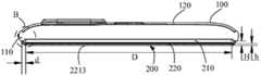
- FIG. 3is a cross-sectional view taken along line A-A of an embodiment of the mobile terminal shown in FIG. 2;
- FIG. 4is an enlarged schematic view of a portion B of the mobile terminal shown in FIG. 3;
- Figure 5is a cross-sectional view taken along line A-A of another embodiment of the mobile terminal shown in Figure 2;
- FIG. 6is an enlarged schematic view showing a portion C of the mobile terminal shown in FIG. 5.
- Terminal devicerefers to a device capable of receiving and/or transmitting a communication signal, including but not limited to being connected via any one or more of the following connection methods:
- wired line connectionsuch as via Public Switched Telephone Networks (PSTN), Digital Subscriber Line (DSL), digital cable, direct cable connection;
- PSTNPublic Switched Telephone Networks
- DSLDigital Subscriber Line
- DSLDigital Subscriber Line
- a wireless interfacesuch as a cellular network, a Wireless Local Area Network (WLAN), a digital television network such as a DVB-H network, a satellite network, an AM-FM broadcast transmitter.
- WLANWireless Local Area Network
- DVB-Hdigital television network
- satellite networkan AM-FM broadcast transmitter.
- a terminal device that is set to communicate through a wireless interfacemay be referred to as a "mobile terminal.”
- mobile terminalsinclude, but are not limited to, the following electronic devices:
- PCSPersonal Communication System
- the mobile terminal 10is a handset.
- the mobile terminal 10includes a rear case 100 and a display screen assembly 200.
- the rear case 100is disposed on one side of the display screen assembly 200 and connected to the display screen assembly 200.
- the rear case 100can support and protect the display assembly 200.
- the rear case 100is substantially rounded and rectangular, and the rear case 100 is convex toward a side away from the display screen assembly 200.
- the rear case 100 and the display screen assembly 200form an accommodation space, and the accommodation space can be used for
- the battery of the mobile terminal 10 and components such as a motherboardare housed.
- the rear case 100may include a middle frame 110 and a battery cover 120, the display screen assembly 200 and the battery cover 120 are respectively connected to the middle frame 110, and the middle frame 110 is located at the battery cover. 120 is between the display assembly 200.
- the middle frame 110is substantially in the shape of a rectangular frame, and the middle frame 110 is disposed on the outer periphery of the display screen assembly 200.
- the inner side of the middle frame 110may be provided with a support structure.
- the middle frame 110is made of a metal material such as an aluminum alloy, and a complicated support structure can be formed on the middle frame 110 by an injection molding process, and components such as a battery and a motherboard of the mobile terminal 10 can be fixed on the support structure.
- the middle frame 110may also be other materials such as stainless steel or ceramic.
- the battery cover 120is made of glass, and the glass may be colored glass or colorless glass. The glass may be transparent or non-transparent.
- the color difference ⁇ E of the color of the outer surface of the middle frame 110 and the color of the outer surface of the battery cover 120is greater than 2.5.
- the outer surface of the middle frame 110 and the outer surface of the battery cover 120have a visually significant chromatic aberration, thereby The appearance of the mobile terminal 10 is beautified.
- the battery cover 120is integrally formed with the middle frame 110, and the battery cover 120 and the middle frame 110 are made of aluminum alloy or stainless steel or ceramic or glass.
- the casing 100is formed and shaped, and the appearance of the mobile terminal 10 is relatively simple and integrated.
- display assembly 200includes display screen 210 and cover plate 220.
- the display screen 210is located on a side of the cover 220 facing the rear case 100.
- the cover plate 220is disposed on the display screen 210 and connected to the rear case 100.
- Display 210can display information and can provide an interface to interact with the user.
- the cover plate 220includes a main body portion 221 and a rim portion 223, and the rim portion 223 is disposed at an edge of the main body portion 221 and connected to the main body portion 221.
- the material of the main body portion 221 and the edge portion 223are both glass, and the main body portion 221 and the edge portion 223 are integrally formed, and the main body portion 221 and the edge portion 223 have a high light transmittance.
- the main body portion 221has a substantially rectangular block shape, and the edge portion 223 is located on both sides in the width direction of the rectangle, that is, the edge portion 223 is connected to the two long sides of the rectangle.
- the body portion 221has a first surface 2211 facing the rear case 100 and a second surface 2213 facing away from the rear case 100.
- the rim portion 223is bent toward the first surface 2211 to protrude from the first surface 2211, and the rim portion 223 and the first surface 2211 form the accommodating groove 300, and the display screen 210 is at least partially received in the accommodating groove 300.
- the display screen 210is attached to the first surface 2211, and the edge portion 223 is connected to the middle frame 110.
- a side of the main body portion 221 facing the display screen 210is provided with a sinking groove 2215.
- the first surface 2211is a bottom wall of the sinking groove 2215, and the display screen 210 is at least partially received in the sinking slot.
- the shape of the sinker 2215matches the shape of the display screen 210, that is, the length and width of the sinker 2215 are respectively equal to the length and width of the display screen 210, and the display screen 210 can be embedded in the sink.
- the display screen 210is attached to the bottom wall of the sinker 2215.
- a plane perpendicular to the thickness direction of the mobile terminal 10is formed, and the plane is used as a main plane, and the orthographic projection of the display screen 210 on the principal plane coincides with the orthographic projection of the sinker 2215 on the principal plane.
- the above arrangementfacilitates the high precision fit of the display screen 210 and the sinker 2215.
- the assembly of the display screen 210 and the cover plate 220is facilitated, and the alignment of the display screen 210 and the cover plate 220 is facilitated, so that the assembly can be improved. Precision and efficiency.
- a dispensing layermay be disposed between the display screen 210 and the bottom wall of the sinking groove 2215, and the dispensing layer is located on the outer circumference of the display screen 210. Further, the dispensing layer is located in the non-display area of display 210. With the dispensing layer, a firm fit of the display screen 210 and the cover plate 220 can be achieved. It can be understood that the width of the sinking groove 2215 can also be slightly larger than the width of the display screen 210, and the length of the sinking groove 2215 can be slightly larger than the length of the display screen 210.
- the ratio of the difference between the width of the sinker 2215 and the width of the display screen 210 to the width of the display screen 210may be less than 2%, the difference between the length of the sinker 2215 and the length of the display screen 210, and the length of the display screen 210.
- the ratiocan be less than 2%.
- This machining errorshould also be considered as the case where the orthographic projection of the display screen 210 on the main plane coincides with the orthographic projection of the sinking groove 2215 on the principal plane, so that the sinking groove 2215 can meet the processing error requirement. And facilitating the centering of the display screen 210 and the cover plate 220.
- the first surface 2211is a flat surface
- the display screen 210is a rigid screen
- the rigid screenis difficult to bend
- the display screen 210is attached to the first surface 2211. Since the first surface 2211 of the main body portion 221 is flat, the display screen 210 can adopt a relatively low cost rigid screen such as an LCD (Liquid Crystal Display) screen, and can be moved without using a costly flexible display screen.
- the terminal 10obtains a better appearance and reduces the cost of the mobile terminal 10.
- the surface of the first surface 2211is attached to the display screen 210 to avoid bending stress on the bonding surface of the display panel 210 and the cover 220, which is advantageous for the firm fit of the display screen 210 and the cover 220.
- the flexible screencan be prevented from being bent on the cover plate 220, causing bending stress on the surface of the flexible screen, resulting in a weak fit of the display screen 210 and the cover plate 220.
- the second surface 2213is planar and the second surface 2213 is parallel to the first surface 2211.
- the second surface 2213may also be a curved surface such as a curved surface.
- the mobile terminal 10may have a curved surface display effect, and the appearance of the mobile terminal 10 may be beautified.
- a plane perpendicular to the longitudinal direction of the mobile terminal 10the shape of the edge portion 223 curved toward one side of the display screen 210 is substantially curved, that is, the surface and orientation of the edge portion 223 toward the inside of the mobile terminal 10.
- the surfaces outside the mobile terminal 10are all curved.
- the mobile terminal 10After the edge portion 223 is disposed on the side of the display screen 210 and connected to the middle frame 110 of the rear case 100, on the one hand, the mobile terminal 10 has a better appearance; on the other hand, the light is refracted by the curved structure of the edge portion 223. And the reflection can make the width of the middle frame 110 appear narrower visually, and can also make the width of the black side of the non-display structure of the outer periphery of the display screen 210 visually narrow.
- the ratio of the width of the orthographic projection of the edge portion 223 on the principal plane to the width of the orthographic projection of the display screen 210 on the principal planeis less than 0.03, and the maximum height of the edge portion 223 from the second surface 2213 is The ratio of the maximum thickness of the main body portion 221 is less than 6.
- the second surface 2213 of the cover plate 220is planar, the second surface 2213 can serve as a main plane, and the width of the orthographic projection of the rim portion 223 on the second surface 2213 and the display screen
- the ratio of the width of the orthographic projection of 210 on the second surface 2213is less than 0.03.
- the ratio of the width of the orthographic projection of 210 on the second surface 2213is less than 0.03.
- the width of the orthographic projection of the display screen 210 on the second surface 2213is D
- the width of the orthographic projection of the edge portion 223 on the second surface 2213is d, then (d/D ) ⁇ 0.03.
- the maximum height of the edge portion 223 from the second surface 2213is H
- the maximum thickness of the body portion 221is h
- the curvature of the edge portion 223is large, and the slit formed by the inner surface of the edge portion 223 and the side surface of the display screen 210 facing the edge portion 223 is narrow.
- This structuremakes the width of the outer ring visually narrow.
- the non-display structure of the outer periphery of the display screen 210is made to have a narrow width of the black side visually presented.
- the curved portion of the edge portion 223 toward the display screen 210is obtained by a hot press forming process.
- the curved structure of the edge portion 223 to the display screen 210can be obtained by CNC (Computer Numerical Control) processing.
- an adhesive layer(not shown) may be disposed in the gap formed by the inner surface of the edge portion 223 and the side surface of the display screen 210 facing the edge portion 223, and the adhesive layer may be a transparent adhesive. By providing the adhesive layer, the display screen 210 and the cover 220 can be firmly connected.
- the orthographic projection of display screen 210 on the major planeis located within the orthographic projection of second surface 2213 on the major plane.
- the second surface 2213completely covers the upper portion of the display screen 210.
- the light of the display screen 210is transmitted through the second surface 2213 by using the consistency of the structure of the second surface 2213.
- the display effectprevents the connection portion between the main body portion 221 and the edge portion 223 from being inconsistent in display effect due to the curvature change, and adversely affects the user experience.
- the mobile terminal 10 and its display screen assembly 200, the cover plate 220 of the display screen assembly 200includes a main body portion 221 and a rim portion 223.
- the rim portion 223is bent toward one side of the rear case 100 and can be connected to the rear case 100.
- the accommodating groove 300is provided on the first surface 2211 of the main body portion 221. Since the rim portion 223 protrudes from the one side of the rear case 100 to form the accommodating groove 300 on the first surface 2211, the accommodating groove 300 is provided for the display screen 210.
- the installation spacecan thus reduce the size of the rear case 100 in the thickness direction of the mobile terminal 10 to make the appearance of the mobile terminal 10 more compact.
- the display screen 210can be embedded in the sinking groove 2215, thereby facilitating the assembly of the display screen 210 and the cover plate 220, and facilitating the display screen 210 and The centering of the cover plate 220 can improve the accuracy and efficiency of the assembly.
- the middle frame 110may include a body 111 and a first boss 113.
- the body 111 and the first boss 113are integrally formed, and a side of the display screen 210 remote from the cover 220 is abutted. Connected to the first boss 113.
- the width of the first boss 113matches the width of the display screen 210, the display screen 210 is disposed on the first boss 113, and an adhesive layer may be disposed between the display screen 210 and the first boss 113 ( The figure is not shown) to connect the display screen 210 to the middle frame 110.
- the first boss 113facilitates the positioning of the display screen 210 on the middle frame 110 and facilitates the connection of the display screen 210 to the middle frame 110.
- the first bosses 113are continuously distributed on the body 111, the first bosses 113 are located on the outer circumference of the display screen 210, and the orthographic projections of the first bosses 113 on the principal plane are rounded rectangles.
- the adhesive layeris disposed between the first boss 113 and the display screen 210, the structure facilitates the firm connection of the display screen 210 and the middle frame 110, and facilitates the sealing connection between the display screen 210 and the middle frame 110 to enhance The waterproof performance of the mobile terminal 10.
- the first bosses 113may also be discontinuous, that is, the first bosses 113 may be spaced apart on the body 111.
- the first bosses 113also facilitate the connection of the display screen 210 to the middle frame 110.
- the middle frame 110may further include a second boss 115, and the second boss 115 is integrally formed with the body 111.
- the second boss 115has a resisting surface 116.
- the resisting surface 116is a flat surface.
- the angle between the resisting surface 116 and the main planeis less than 45 degrees, and the edge portion 223 abuts against the resisting surface 116.
- the second boss 115protrudes toward the first boss 113 toward the side close to the cover 220, and the resisting surface 116 is inclined toward the inside from the outside of the mobile terminal 10.
- FIG. 6the embodiment shown in FIG.
- the mobile terminal 10is horizontally placed, and the left resisting surface 116 is rotated clockwise by an angle of less than 45 degrees to coincide with the horizontal plane, and the right resisting surface 116 is counterclockwise. The direction is rotated by an angle of less than 45 degrees to coincide with the horizontal plane.
- an adhesive layermay be disposed on the resisting surface 116, and the edge portion 223 is connected to the middle frame 110 through an adhesive layer.
- the structure of the abutting surface 116is such that after the cover plate 220 is connected to the middle frame 110, the supporting force of the resisting surface 116 to the cover plate 220 has a component force distributed along the width direction of the cover plate 220 and directed to the inside of the mobile terminal 10,
- the component forcecauses the edge portions 223 on both sides of the main body portion 221 to have an inward tendency. Therefore, the edge portions 223 on both sides of the main body portion 221 can be prevented from being stretched outward, and the reliability of the connection between the cover plate 220 and the middle frame 110 can be ensured.
- the second bosses 115are continuously distributed on the body 111, the second bosses 115 are located on the outer circumference of the first bosses 113, and the orthographic projections of the second bosses 115 on the principal plane are rounded rectangles.
- the adhesive layeris disposed between the second boss 115 and the cover 220, the structure facilitates the firm connection of the cover 220 to the middle frame 110 and facilitates the sealing connection of the cover 220 to the middle frame 110 to enhance The waterproof performance of the mobile terminal 10.
- the second bosses 115may also be discontinuous, that is, the second bosses 115 are spaced apart on the body 111, and the second bosses 115 also facilitate the connection of the cover plate 220 to the middle frame 110.
- the middle frame 110may further include a third boss 117, and the third boss 117 is integrally formed with the body 111.
- the third boss 117is located on a side of the rim portion 223 remote from the display screen 210, and the rim portion 223 abuts against the third boss 117.
- the third boss 117protrudes outwardly from the side closer to the second surface 2213 on the second boss 115, and the third boss 117 abuts against the edge portion 223 and the edge
- the edge of the portion 223forms a half-pack structure to facilitate the positioning of the cover 220 on the rear case 100, and can protect the cover plate 220 from damage caused by accidental collision of the edge of the cover plate 220.
- the third bosses 117are continuously distributed on the body 111, the third bosses 117 are located on the outer circumference of the second bosses 115, and the orthographic projections of the third bosses 117 on the principal plane are rounded rectangles.
- the third boss 117facilitates a secure connection of the cover plate 220 to the middle frame 110.
- the third bosses 117may also be discontinuous, that is, the third bosses 117 are spaced apart on the body 111, and the third bosses 117 also facilitate the connection of the cover plate 220 to the middle frame 110.
- the outer surface of the middle frame 110extends along the thickness direction of the mobile terminal 10 as an arc surface, and the curved surface has a curved curvature slightly larger than the curved curvature of the edge portion 223, so that the side surface of the mobile terminal 10 is a curved surface.
- the structureis advantageous for beautifying the appearance of the mobile terminal 10 and facilitating the improvement of the overall appearance of the mobile terminal 10.
Landscapes
- Engineering & Computer Science (AREA)
- Computer Hardware Design (AREA)
- Theoretical Computer Science (AREA)
- General Engineering & Computer Science (AREA)
- Human Computer Interaction (AREA)
- Physics & Mathematics (AREA)
- General Physics & Mathematics (AREA)
- Signal Processing (AREA)
- Power Engineering (AREA)
- Telephone Set Structure (AREA)
- Devices For Indicating Variable Information By Combining Individual Elements (AREA)
Abstract
Description
Translated fromChinese本发明涉及移动终端技术领域。The present invention relates to the field of mobile terminal technology.
一般的移动终端包括盖板和显示屏,盖板盖设于显示屏上。在盖板与显示屏的组装过程中,显示屏在盖板上难以实现对中。A typical mobile terminal includes a cover and a display, and the cover is disposed on the display. During the assembly of the cover and the display, the display is difficult to center on the cover.
发明内容Summary of the invention
基于此,有必要提供一种移动终端及其显示屏组件。Based on this, it is necessary to provide a mobile terminal and its display component.
一种显示屏组件,用于与移动终端的后壳连接,所述显示屏组件包括:A display screen assembly for connecting to a rear case of a mobile terminal, the display screen assembly comprising:
显示屏;及Display screen; and
盖板,盖设于所述显示屏上;所述盖板包括主体部和边沿部,所述边沿部设置于所述主体部的边缘并与所述主体部连接;所述主体部具有朝向所述后壳的第一表面和背向所述后壳的第二表面;所述边沿部向所述第一表面的一侧弯曲以凸出于所述第一表面上,且所述边沿部与所述第一表面形成容置槽,所述显示屏至少部分收容于所述容置槽内,所述边沿部用于与所述后壳连接;所述主体部的朝向所述显示屏的一侧开设有沉槽,所述第一表面为所述沉槽的底壁,所述显示屏至少部分收容于所述沉槽内;所述显示屏在主平面上的正投影与所述沉槽在主平面上的正投影重合,所述主平面为垂直于所述移动终端的厚度方向的平面。a cover plate covering the display screen; the cover plate includes a main body portion and a rim portion, the rim portion is disposed at an edge of the main body portion and connected to the main body portion; the main body portion has an orientation a first surface of the rear case and a second surface facing away from the rear case; the rim portion is curved toward a side of the first surface to protrude from the first surface, and the rim portion is The first surface is formed with a receiving groove, and the display screen is at least partially received in the receiving groove, the edge portion is for connecting with the rear case; and a part of the main body portion facing the display screen The side surface is provided with a sinking groove, the first surface is a bottom wall of the sinking groove, the display screen is at least partially received in the sinking groove; the orthographic projection of the display screen on the main plane and the sinking groove The orthographic projections on the principal plane coincide, and the principal plane is a plane perpendicular to the thickness direction of the mobile terminal.
上述移动终端及其显示屏组件,显示屏组件的盖板包括主体部和边沿部,由于边沿部向后壳的一侧凸出于第一表面上形成容置槽,容置槽为显示屏的提供了安装空间,因此可以减小后壳在移动终端的厚度方向上的尺寸,以使移动终端的外观更加简洁。由于主体部的朝向显示屏的一侧开设有沉槽,显 示屏至少部分收容于沉槽内,沉槽可以与显示屏匹配,以利于显示屏在盖板上的定位,并有利于盖板与显示屏的对中。In the above mobile terminal and its display screen assembly, the cover plate of the display screen assembly includes a main body portion and a rim portion, and the accommodating groove is a display screen because a side of the rim portion protrudes from a side of the rear case to form a receiving groove on the first surface. The installation space is provided, so that the size of the rear case in the thickness direction of the mobile terminal can be reduced to make the appearance of the mobile terminal more compact. Since the side of the main body facing the display screen is provided with a sinking groove, the display screen is at least partially received in the sinking groove, and the sinking groove can be matched with the display screen to facilitate the positioning of the display screen on the cover plate, and is beneficial to the cover plate and the cover plate. The alignment of the display.
为了更清楚地说明本发明实施例或现有技术中的技术方案,下面将对实施例或现有技术描述中所需要使用的附图作简单地介绍,显而易见地,下面描述中的附图仅仅是本发明的一些实施例,对于本领域普通技术人员来讲,在不付出创造性劳动的前提下,还可以根据这些附图获得其他实施例的附图。In order to more clearly illustrate the embodiments of the present invention or the technical solutions in the prior art, the drawings used in the embodiments or the description of the prior art will be briefly described below. Obviously, the drawings in the following description are only It is a certain embodiment of the present invention, and those skilled in the art can obtain drawings of other embodiments according to the drawings without any creative work.
图1为一实施例中移动终端的立体图;1 is a perspective view of a mobile terminal in an embodiment;
图2为图1所示移动终端的主视图;Figure 2 is a front elevational view of the mobile terminal shown in Figure 1;
图3为图2所示移动终端的一实施例中沿A-A处的剖视图;3 is a cross-sectional view taken along line A-A of an embodiment of the mobile terminal shown in FIG. 2;
图4为图3所示移动终端的B处的放大示意图;4 is an enlarged schematic view of a portion B of the mobile terminal shown in FIG. 3;
图5为图2所示移动终端的另一实施例中沿A-A处的剖视图;Figure 5 is a cross-sectional view taken along line A-A of another embodiment of the mobile terminal shown in Figure 2;
图6为图5所示移动终端的C处的放大示意图。FIG. 6 is an enlarged schematic view showing a portion C of the mobile terminal shown in FIG. 5.
为了便于理解本发明,下面将参照相关附图对本发明进行更全面的描述。附图中给出了本发明的较佳的实施例。但是,本发明可以以许多不同的形式来实现,并不限于本文所描述的实施例。相反地,提供这些实施例的目的是使对本发明的公开内容的理解更加透彻全面。In order to facilitate the understanding of the present invention, the present invention will be described more fully hereinafter with reference to the accompanying drawings. Preferred embodiments of the invention are shown in the drawings. However, the invention may be embodied in many different forms and is not limited to the embodiments described herein. Rather, these embodiments are provided so that the understanding of the present disclosure will be more fully understood.
作为在此使用的“终端设备”指包括但不限于经由以下任意一种或者数种连接方式连接的能够接收和/或发送通信信号的装置:"Terminal device" as used herein refers to a device capable of receiving and/or transmitting a communication signal, including but not limited to being connected via any one or more of the following connection methods:
(1)经由有线线路连接方式,如经由公共交换电话网络(Public Switched Telephone Networks,PSTN)、数字用户线路(Digital Subscriber Line,DSL)、数字电缆、直接电缆连接;(1) via wired line connection, such as via Public Switched Telephone Networks (PSTN), Digital Subscriber Line (DSL), digital cable, direct cable connection;
(2)经由无线接口方式,如蜂窝网络、无线局域网(Wireless Local Area Network,WLAN)、诸如DVB-H网络的数字电视网络、卫星网络、AM-FM 广播发送器。(2) via a wireless interface, such as a cellular network, a Wireless Local Area Network (WLAN), a digital television network such as a DVB-H network, a satellite network, an AM-FM broadcast transmitter.
被设置成通过无线接口通信的终端设备可以被称为“移动终端”。移动终端的示例包括但不限于以下电子装置:A terminal device that is set to communicate through a wireless interface may be referred to as a "mobile terminal." Examples of mobile terminals include, but are not limited to, the following electronic devices:
(1)卫星电话或蜂窝电话;(1) a satellite phone or a cellular phone;
(2)可以组合蜂窝无线电电话与数据处理、传真以及数据通信能力的个人通信系统(Personal Communications System,PCS)终端;(2) Personal Communication System (PCS) terminals that can combine cellular radiotelephone with data processing, fax, and data communication capabilities;
(3)无线电电话、寻呼机、因特网/内联网接入、Web浏览器、记事簿、日历、配备有全球定位系统(Global Positioning System,GPS)接收器的个人数字助理(Personal Digital Assistant,PDA);(3) Radiotelephone, pager, Internet/Intranet access, Web browser, Notepad, calendar, Personal Digital Assistant (PDA) equipped with a Global Positioning System (GPS) receiver;
(4)常规膝上型和/或掌上型接收器;(4) conventional laptop and/or palm receivers;
(5)常规膝上型和/或掌上型无线电电话收发器等。(5) Conventional laptop and/or palm-type radiotelephone transceivers and the like.
参考图1和图2,在一实施例中,移动终端10为手机。移动终端10包括后壳100和显示屏组件200,后壳100盖设于显示屏组件200的一侧并与显示屏组件200连接。后壳100可以对显示屏组件200起到支撑和保护作用。在一实施例中,后壳100大致呈圆角矩形状,后壳100向远离显示屏组件200的一侧外凸,后壳100与显示屏组件200之间形成容纳空间,该容纳空间可用于收容移动终端10的电池和主板等元器件。进一步,参考图3和图4,在一实施例中,后壳100可以包括中框110和电池盖120,显示屏组件200和电池盖120分别与中框110连接,且中框110位于电池盖120与显示屏组件200之间。Referring to Figures 1 and 2, in one embodiment, the
在一实施例中,中框110大致呈矩形框状,中框110设于显示屏组件200外周,中框110的内侧可以设置支撑结构。在一实施例中,中框110为金属材质例如铝合金,中框110上通过注塑成型工艺可形成复杂的支撑结构,移动终端10的电池和主板等元器件可以固定于支撑结构上。在一实施例中,中框110也可以为其他材质例如不锈钢或陶瓷。在一实施例中,电池盖120的材质为玻璃,玻璃可以为有色玻璃,也可以为无色玻璃。玻璃可以为透明状,也可以为非透明状。在一实施例中,中框110的外表面的颜色与电池盖120 的外表面的颜色的色差值ΔE大于2.5。中框110的外表面的颜色与电池盖120的外表面的颜色的色差值ΔE处于上述范围时,中框110的外表面与电池盖120的外表面在视觉上有明显的色差,从而可以美化移动终端10的外观。进一步,参考图5和图6,在一实施例中,电池盖120与中框110一体成型,电池盖120和中框110的材质均为铝合金或不锈钢或陶瓷或玻璃,上述结构有利于后壳100的加工成型,并可使得移动终端10的外观较为简洁和一体化。In an embodiment, the
参考图3和图4,在一实施例中,显示屏组件200包括显示屏210和盖板220。显示屏210位于盖板220的朝向后壳100的一侧,盖板220盖设于显示屏210上并与后壳100连接。显示屏210可以显示信息,并可提供与用户交互的界面。在一实施例中,盖板220包括主体部221和边沿部223,边沿部223设置于主体部221的边缘并与主体部221连接。在一实施例中,主体部221和边沿部223的材质均为玻璃,主体部221和边沿部223一体成型,主体部221和边沿部223具有较高的透光率。在一实施例中,主体部221大致呈矩形块状,边沿部223位于矩形的宽度方向的两侧,即边沿部223与矩形的两条长边连接。主体部221具有朝向后壳100的第一表面2211和背向后壳100的第二表面2213。边沿部223向第一表面2211的一侧弯曲以凸出于第一表面2211上,且边沿部223与第一表面2211形成容置槽300,显示屏210至少部分收容于容置槽300内,且显示屏210贴合于第一表面2211上,边沿部223与中框110连接。Referring to Figures 3 and 4, in an embodiment,
进一步,参考图4,在一实施例中,主体部221的朝向显示屏210的一侧开设有沉槽2215,第一表面2211为沉槽2215的底壁,显示屏210至少部分收容于沉槽2215内。具体地,在一实施例中,沉槽2215的形状与显示屏210的形状匹配,即沉槽2215的长度和宽度分别与显示屏210的长度与宽度对应相等,显示屏210可以嵌设于沉槽2215内,显示屏210与沉槽2215的底壁贴合。进一步,在一实施例中,作垂直于移动终端10的厚度方向的平面,并以该平面作为主平面,显示屏210在主平面上的正投影与沉槽2215在主平面上的正投影重合,上述设置有利于显示屏210与沉槽2215的高精度配合。 通过设置沉槽2215,并将显示屏210嵌设于沉槽2215内,有利于显示屏210与盖板220的组装,且有利于显示屏210与盖板220的对中,从而可以提升装配的精度和效率。Further, referring to FIG. 4, in one embodiment, a side of the
可以理解的是,显示屏210与沉槽2215的底壁之间可以设置点胶层(图未标),点胶层位于显示屏210的外周。进一步,点胶层位于显示屏210的非显示区域。利用点胶层,可以实现显示屏210与盖板220的牢固贴合。可以理解的是,沉槽2215的宽度也可以略大于显示屏210的宽度,沉槽2215的长度可以略大于显示屏210的长度。例如,沉槽2215的宽度与显示屏210的宽度的差值与显示屏210的宽度的比值可以小于2%,沉槽2215的长度与显示屏210的长度的差值与显示屏210的长度的比值可以小于2%,这种加工误差也应视为显示屏210在主平面上的正投影与沉槽2215在主平面上的正投影重合的情况,以使沉槽2215能够满足加工误差的要求,并有利于显示屏210与盖板220的对中设置。It can be understood that a dispensing layer (not labeled) may be disposed between the
在一实施例中,第一表面2211为平面,显示屏210为刚性屏,刚性屏难以弯曲,显示屏210贴合于第一表面2211上。由于主体部221的第一表面2211为平面,显示屏210就可以采用成本相对较低的刚性屏例如LCD(Liquid Crystal Display,液晶显示)屏,无需使用成本较高的柔性显示屏即可使移动终端10获得较佳外观,并降低移动终端10的成本。利用第一表面2211的平面与显示屏210贴合,还可避免显示屏210与盖板220的贴合面产生弯曲应力,有利于显示屏210与盖板220的牢固贴合。这种结构,可避免采用柔性屏弯曲贴合于盖板220上,使柔性屏的表面产生弯曲应力,导致显示屏210与盖板220的贴合不牢固。In one embodiment, the
在图4所示实施例中,第二表面2213为平面,第二表面2213与第一表面2211平行。在其他实施方式中,第二表面2213也可以为曲面例如弧面,第二表面2213采用弧面时,可以使得移动终端10具有曲面显示效果,并可美化移动终端10的外观。在一实施例中,作垂直于移动终端10的长度方向的平面,边沿部223向显示屏210的一侧弯曲的形状大致呈弧形,即边沿部 223的朝向移动终端10内部的表面和朝向移动终端10外部的表面均为弧面状。在边沿部223设于显示屏210的侧面并与后壳100的中框110连接后,一方面使得移动终端10具有较佳的外观;另一方面,利用边沿部223的弯曲结构对光线的折射和反射,既能使得中框110的宽度在视觉上显得较窄,还能够使得显示屏210的外周的非显示结构在视觉上呈现的黑边的宽度较窄。In the embodiment shown in FIG. 4, the
进一步,在一实施例中,边沿部223在主平面上的正投影的宽度与显示屏210在主平面上的正投影的宽度的比值小于0.03,边沿部223距第二表面2213的最大高度与主体部221的最大厚度的比值小于6。具体地,参考图3,在一实施例中,盖板220的第二表面2213为平面,第二表面2213可以作为主平面,边沿部223在第二表面2213上的正投影的宽度与显示屏210在第二表面2213上的正投影的宽度的比值小于0.03。例如,在图3所示实施例中,显示屏210在第二表面2213上的正投影的宽度为D,边沿部223在第二表面2213上的正投影的宽度为d,则(d/D)<0.03。在图3所示实施例中,边沿部223距第二表面2213的最大高度为H,主体部221的最大厚度为h,则(H/h)<6。上述结构,边沿部223的弯曲弧度较大,边沿部223的内表面与显示屏210的朝向边沿部223的侧面形成的缝隙较窄,这种结构使得外圈的宽度在视觉上显得较窄,并使得显示屏210的外周的非显示结构在视觉上呈现的黑边的宽度较窄。Further, in an embodiment, the ratio of the width of the orthographic projection of the
在一实施例中,边沿部223向显示屏210的弯曲结构通过热压成型工艺获得。在其他实施方式中,边沿部223向显示屏210的弯曲结构可以通过CNC(Computer Numerical Control,数控机床)加工的方式获得。在一实施例中,边沿部223的内表面与显示屏210的朝向边沿部223的侧面形成的缝隙中可以设置粘接层(图未示),粘接层可以为透明的粘胶。通过设置粘接层,可以使显示屏210和盖板220连接牢固。在一实施例中,显示屏210在主平面上的正投影位于第二表面2213在主平面上的正投影内。上述设置,第二表面2213完全覆盖于显示屏210的上方,当显示屏210显示信息时,利用第二表面2213的结构的一致性,显示屏210的光线透过第二表面2213,可以呈现 一致的显示效果,可防止主体部221与边沿部223的连接部位因曲率变化造成显示效果不一致,对用户体验产生不利的影响。In an embodiment, the curved portion of the
上述移动终端10及其显示屏组件200,显示屏组件200的盖板220包括主体部221和边沿部223,边沿部223向后壳100的一侧弯曲并可连接于后壳100上,显示屏210贴合于主体部221的第一表面2211上,由于边沿部223向后壳100的一侧凸出于第一表面2211上形成容置槽300,容置槽300为显示屏210的提供了安装空间,因此可以减小后壳100在移动终端10的厚度方向上的尺寸,以使移动终端10的外观更加简洁。由于主体部221的朝向显示屏210的一侧开设有沉槽2215,显示屏210可以嵌设于沉槽2215内,从而有利于显示屏210与盖板220的组装,且有利于显示屏210与盖板220的对中,从而可以提升装配的精度和效率。The
参考图5和图6,在一实施例中,中框110可以包括本体111和第一凸台113,本体111和第一凸台113一体成型,显示屏210的远离盖板220的一侧抵接于第一凸台113上。在一实施例中,第一凸台113的宽度与显示屏210的宽度匹配,显示屏210设置于第一凸台113上,显示屏210与第一凸台113之间可以设置粘胶层(图未示),以使显示屏210与中框110连接。第一凸台113有利于显示屏210在中框110上的定位,并有利于显示屏210与中框110的连接。在一实施例中,第一凸台113在本体111上连续分布,第一凸台113位于显示屏210的外周,且第一凸台113在主平面上的正投影呈圆角矩形。当第一凸台113与显示屏210之间设置粘胶层时,这种结构有利于显示屏210与中框110的牢固连接,并有利于显示屏210与中框110的密封连接,以提升移动终端10的防水性能。在其他实施方式中,第一凸台113也可以是不连续的,即第一凸台113在本体111上可以间隔分布,第一凸台113同样有利于显示屏210与中框110的连接。Referring to FIG. 5 and FIG. 6, in an embodiment, the
在一实施例中,中框110还可以包括第二凸台115,第二凸台115与本体111一体成型。第二凸台115具有抵持面116,抵持面116为平面,抵持面116与主平面的夹角小于45度,边沿部223抵接于抵持面116上。具体地,在图 6所示实施例中,第二凸台115向靠近盖板220的一侧凸出于第一凸台113上,抵持面116由移动终端10的外部向内部倾斜。在图6所示实施例中,移动终端10呈水平放置,左侧的抵持面116沿顺时针方向旋转一个小于45度的角度即可与水平面重合,右侧的抵持面116沿逆时针方向旋转一个小于45度的角度即可与水平面重合。在一实施例中,抵持面116上可以设置粘胶层,边沿部223通过粘胶层与中框110连接。上述抵持面116的结构,在盖板220与中框110连接后,抵持面116对盖板220的支撑力具有沿盖板220的宽度方向分布并指向移动终端10内部的分力,该分力使得主体部221两侧的边沿部223有向内靠近的趋势,因此能够防止主体部221两侧的边沿部223外张,进而能够保证盖板220与中框110的连接的可靠性。In an embodiment, the
在一实施例中,第二凸台115在本体111上连续分布,第二凸台115位于第一凸台113的外周,且第二凸台115在主平面上的正投影呈圆角矩形。当第二凸台115与盖板220之间设置粘胶层时,这种结构有利于盖板220与中框110的牢固连接,并有利于盖板220与中框110的密封连接,以提升移动终端10的防水性能。在其他实施方式中,第二凸台115也可以是不连续的,即第二凸台115在本体111上间隔分布,第二凸台115同样有利于盖板220与中框110的连接。In an embodiment, the
在一实施例中,中框110还可以包括第三凸台117,第三凸台117与本体111一体成型。第三凸台117位于边沿部223的远离显示屏210的一侧,且边沿部223与第三凸台117抵接。具体地,在图6所示实施例中,第三凸台117向靠近第二表面2213的一侧外凸于第二凸台115上,第三凸台117与边沿部223抵接并对边沿部223的边缘形成半包结构,以利于盖板220在后壳100上的定位,并能够对盖板220起到保护作用,防止盖板220的边缘因意外碰撞而造成损伤。在一实施例中,第三凸台117在本体111上连续分布,第三凸台117位于第二凸台115的外周,且第三凸台117在主平面上的正投影呈圆角矩形。第三凸台117有利于盖板220与中框110的牢固连接。在其他实施方式中,第三凸台117也可以是不连续的,即第三凸台117在本体111上 间隔分布,第三凸台117同样有利于盖板220与中框110的连接。在一实施例中,中框110的外侧沿移动终端10厚度方向上延伸的表面为弧形面,该弧形面的弯曲弧度略大于边沿部223的弯曲弧度,使得移动终端10的侧面为曲面结构,有利于美化移动终端10的外观,并有利于提升移动终端10的外观的整体性。In an embodiment, the
以上所述实施例的各技术特征可以进行任意的组合,为使描述简洁,未对上述实施例中的各个技术特征所有可能的组合都进行描述,然而,只要这些技术特征的组合不存在矛盾,都应当认为是本说明书记载的范围。The technical features of the above-described embodiments may be arbitrarily combined. For the sake of brevity of description, all possible combinations of the technical features in the above embodiments are not described. However, as long as there is no contradiction between the combinations of these technical features, All should be considered as the scope of this manual.
以上所述实施例仅表达了本发明的几种实施方式,其描述较为具体和详细,但并不能因此而理解为对发明专利范围的限制。应当指出的是,对于本领域的普通技术人员来说,在不脱离本发明构思的前提下,还可以做出若干变形和改进,这些都属于本发明的保护范围。因此,本发明专利的保护范围应以所附权利要求为准。The above-described embodiments are merely illustrative of several embodiments of the present invention, and the description thereof is more specific and detailed, but is not to be construed as limiting the scope of the invention. It should be noted that a number of variations and modifications may be made by those skilled in the art without departing from the spirit and scope of the invention. Therefore, the scope of the invention should be determined by the appended claims.
Claims (20)
Translated fromChinesePriority Applications (2)
| Application Number | Priority Date | Filing Date | Title |
|---|---|---|---|
| EP18889087.5AEP3726819A4 (en) | 2017-12-12 | 2018-11-12 | MOBILE TERMINAL AND ITS DISPLAY ARRANGEMENT |
| US16/884,596US20200288005A1 (en) | 2017-12-12 | 2020-05-27 | Display Assembly and Terminal |
Applications Claiming Priority (4)
| Application Number | Priority Date | Filing Date | Title |
|---|---|---|---|
| CN201721743614.4UCN207491012U (en) | 2017-12-12 | 2017-12-12 | Mobile terminal and its display screen component |
| CN201711322950.6ACN109922170B (en) | 2017-12-12 | 2017-12-12 | Mobile terminals and display components thereof |
| CN201721743614.4 | 2017-12-12 | ||
| CN201711322950.6 | 2017-12-12 |
Related Child Applications (1)
| Application Number | Title | Priority Date | Filing Date |
|---|---|---|---|
| US16/884,596ContinuationUS20200288005A1 (en) | 2017-12-12 | 2020-05-27 | Display Assembly and Terminal |
Publications (1)
| Publication Number | Publication Date |
|---|---|
| WO2019114475A1true WO2019114475A1 (en) | 2019-06-20 |
Family
ID=66819915
Family Applications (1)
| Application Number | Title | Priority Date | Filing Date |
|---|---|---|---|
| PCT/CN2018/114959CeasedWO2019114475A1 (en) | 2017-12-12 | 2018-11-12 | Mobile terminal and its display screen assembly thereof |
Country Status (3)
| Country | Link |
|---|---|
| US (1) | US20200288005A1 (en) |
| EP (1) | EP3726819A4 (en) |
| WO (1) | WO2019114475A1 (en) |
Cited By (1)
| Publication number | Priority date | Publication date | Assignee | Title |
|---|---|---|---|---|
| CN117177486A (en)* | 2022-05-27 | 2023-12-05 | 荣耀终端有限公司 | an electronic device |
Families Citing this family (1)
| Publication number | Priority date | Publication date | Assignee | Title |
|---|---|---|---|---|
| USD803209S1 (en)* | 2016-03-07 | 2017-11-21 | Apple Inc. | Electronic device |
Citations (7)
| Publication number | Priority date | Publication date | Assignee | Title |
|---|---|---|---|---|
| WO2004080038A1 (en)* | 2003-03-04 | 2004-09-16 | Siemens Aktiengesellschaft | Mobile telephone comprising an integrated receiver and a hollow space formed by a shell arranged therebefore |
| CN104660750A (en)* | 2015-02-09 | 2015-05-27 | 广东欧珀移动通信有限公司 | Mobile phone touch screen component mounting method, gluing jig and gluing process |
| CN204761507U (en)* | 2015-07-09 | 2015-11-11 | 深圳市润江南科技有限公司 | Dust -protection type cell -phone glass screen apron |
| CN105227715A (en)* | 2015-10-23 | 2016-01-06 | 广东欧珀移动通信有限公司 | Mobile device, housing unit and manufacture method thereof |
| CN206332719U (en)* | 2017-01-09 | 2017-07-14 | 广东欧珀移动通信有限公司 | Display screen component, housing unit and terminal |
| CN107168464A (en)* | 2017-05-11 | 2017-09-15 | 努比亚技术有限公司 | Terminal device |
| CN207491012U (en)* | 2017-12-12 | 2018-06-12 | 广东欧珀移动通信有限公司 | Mobile terminal and its display screen component |
Family Cites Families (2)
| Publication number | Priority date | Publication date | Assignee | Title |
|---|---|---|---|---|
| US8773848B2 (en)* | 2012-01-25 | 2014-07-08 | Apple Inc. | Fused glass device housings |
| US10069952B2 (en)* | 2014-02-13 | 2018-09-04 | Magna Mirrors Of America, Inc. | Cover glass for mobile device |
- 2018
- 2018-11-12WOPCT/CN2018/114959patent/WO2019114475A1/ennot_activeCeased
- 2018-11-12EPEP18889087.5Apatent/EP3726819A4/ennot_activeWithdrawn
- 2020
- 2020-05-27USUS16/884,596patent/US20200288005A1/ennot_activeAbandoned
Patent Citations (7)
| Publication number | Priority date | Publication date | Assignee | Title |
|---|---|---|---|---|
| WO2004080038A1 (en)* | 2003-03-04 | 2004-09-16 | Siemens Aktiengesellschaft | Mobile telephone comprising an integrated receiver and a hollow space formed by a shell arranged therebefore |
| CN104660750A (en)* | 2015-02-09 | 2015-05-27 | 广东欧珀移动通信有限公司 | Mobile phone touch screen component mounting method, gluing jig and gluing process |
| CN204761507U (en)* | 2015-07-09 | 2015-11-11 | 深圳市润江南科技有限公司 | Dust -protection type cell -phone glass screen apron |
| CN105227715A (en)* | 2015-10-23 | 2016-01-06 | 广东欧珀移动通信有限公司 | Mobile device, housing unit and manufacture method thereof |
| CN206332719U (en)* | 2017-01-09 | 2017-07-14 | 广东欧珀移动通信有限公司 | Display screen component, housing unit and terminal |
| CN107168464A (en)* | 2017-05-11 | 2017-09-15 | 努比亚技术有限公司 | Terminal device |
| CN207491012U (en)* | 2017-12-12 | 2018-06-12 | 广东欧珀移动通信有限公司 | Mobile terminal and its display screen component |
Non-Patent Citations (1)
| Title |
|---|
| See also references ofEP3726819A4* |
Cited By (1)
| Publication number | Priority date | Publication date | Assignee | Title |
|---|---|---|---|---|
| CN117177486A (en)* | 2022-05-27 | 2023-12-05 | 荣耀终端有限公司 | an electronic device |
Also Published As
| Publication number | Publication date |
|---|---|
| US20200288005A1 (en) | 2020-09-10 |
| EP3726819A4 (en) | 2021-01-20 |
| EP3726819A1 (en) | 2020-10-21 |
Similar Documents
| Publication | Publication Date | Title |
|---|---|---|
| CN207491012U (en) | Mobile terminal and its display screen component | |
| US10620665B2 (en) | Terminal display assembly and mobile terminal | |
| US10917506B2 (en) | Terminal display assembly and mobile terminal | |
| US10890940B2 (en) | Display screen, terminal display screen assembly, and mobile terminal | |
| CN114125103B (en) | Connecting ring, middle frame, electronic device, display module and assembly method thereof | |
| CN210137349U (en) | Electronic equipment | |
| CN104866019A (en) | Display components and terminals | |
| CN109922170B (en) | Mobile terminals and display components thereof | |
| CN108429838B (en) | Display screen assembly and electronic equipment | |
| CN210927685U (en) | Electronic equipment, display screen assembly and display screen cover plate thereof | |
| CN110166679B (en) | Electronic equipment | |
| CN209964150U (en) | Camera assembly and electronic equipment | |
| WO2019141060A1 (en) | Mobile terminal | |
| CN110266852A (en) | Electronic equipment | |
| CN110278359B (en) | Electronic device and method of assembling the same | |
| WO2019114475A1 (en) | Mobile terminal and its display screen assembly thereof | |
| CN110312012A (en) | Electronic equipment | |
| CN209964153U (en) | Electronic equipment | |
| CN112671955B (en) | Electronic device | |
| CN209659416U (en) | Shell component and mobile terminal | |
| CN108124030A (en) | Cover plate, display screen assembly and mobile terminal | |
| CN110049150B (en) | mobile terminal | |
| CN208079204U (en) | The support construction of mobile terminal and its box sound chambers | |
| CN209964149U (en) | Electronic device | |
| CN207251780U (en) | Camera guard assembly, camera module and mobile terminal |
Legal Events
| Date | Code | Title | Description |
|---|---|---|---|
| 121 | Ep: the epo has been informed by wipo that ep was designated in this application | Ref document number:18889087 Country of ref document:EP Kind code of ref document:A1 | |
| NENP | Non-entry into the national phase | Ref country code:DE | |
| ENP | Entry into the national phase | Ref document number:2018889087 Country of ref document:EP Effective date:20200713 |