WO2019111548A1 - Image display device - Google Patents
Image display deviceDownload PDFInfo
- Publication number
- WO2019111548A1 WO2019111548A1PCT/JP2018/038632JP2018038632WWO2019111548A1WO 2019111548 A1WO2019111548 A1WO 2019111548A1JP 2018038632 WJP2018038632 WJP 2018038632WWO 2019111548 A1WO2019111548 A1WO 2019111548A1
- Authority
- WO
- WIPO (PCT)
- Prior art keywords
- light source
- temperature
- unit
- image display
- light
- Prior art date
- Legal status (The legal status is an assumption and is not a legal conclusion. Google has not performed a legal analysis and makes no representation as to the accuracy of the status listed.)
- Ceased
Links
Images


Classifications
- H—ELECTRICITY
- H04—ELECTRIC COMMUNICATION TECHNIQUE
- H04N—PICTORIAL COMMUNICATION, e.g. TELEVISION
- H04N9/00—Details of colour television systems
- H04N9/12—Picture reproducers
- H04N9/31—Projection devices for colour picture display, e.g. using electronic spatial light modulators [ESLM]
- H04N9/3191—Testing thereof
- H04N9/3194—Testing thereof including sensor feedback
- G—PHYSICS
- G03—PHOTOGRAPHY; CINEMATOGRAPHY; ANALOGOUS TECHNIQUES USING WAVES OTHER THAN OPTICAL WAVES; ELECTROGRAPHY; HOLOGRAPHY
- G03B—APPARATUS OR ARRANGEMENTS FOR TAKING PHOTOGRAPHS OR FOR PROJECTING OR VIEWING THEM; APPARATUS OR ARRANGEMENTS EMPLOYING ANALOGOUS TECHNIQUES USING WAVES OTHER THAN OPTICAL WAVES; ACCESSORIES THEREFOR
- G03B21/00—Projectors or projection-type viewers; Accessories therefor
- G03B21/14—Details
- H—ELECTRICITY
- H04—ELECTRIC COMMUNICATION TECHNIQUE
- H04N—PICTORIAL COMMUNICATION, e.g. TELEVISION
- H04N9/00—Details of colour television systems
- H04N9/12—Picture reproducers
- H04N9/31—Projection devices for colour picture display, e.g. using electronic spatial light modulators [ESLM]
- H04N9/3141—Constructional details thereof
- H04N9/3144—Cooling systems
- H—ELECTRICITY
- H04—ELECTRIC COMMUNICATION TECHNIQUE
- H04N—PICTORIAL COMMUNICATION, e.g. TELEVISION
- H04N9/00—Details of colour television systems
- H04N9/12—Picture reproducers
- H04N9/31—Projection devices for colour picture display, e.g. using electronic spatial light modulators [ESLM]
- H04N9/3141—Constructional details thereof
- H04N9/315—Modulator illumination systems
- H04N9/3155—Modulator illumination systems for controlling the light source
- H—ELECTRICITY
- H04—ELECTRIC COMMUNICATION TECHNIQUE
- H04N—PICTORIAL COMMUNICATION, e.g. TELEVISION
- H04N9/00—Details of colour television systems
- H04N9/12—Picture reproducers
- H04N9/31—Projection devices for colour picture display, e.g. using electronic spatial light modulators [ESLM]
- H04N9/3141—Constructional details thereof
- H04N9/315—Modulator illumination systems
- H04N9/3161—Modulator illumination systems using laser light sources
Definitions
- the present technologyrelates to an image display device such as a projector.
- an image display apparatussuch as a projector has been widely used.
- light from a light sourceis modulated by a light modulation element such as a liquid crystal element, and the modulated light is projected on a screen or the like to display an image.
- a light sourcea mercury lamp, a xenon lamp, an LED (Light Emitting Diode), an LD (Laser Diode) or the like is used.
- solid-state light sourcessuch as LEDs and LDs have a long life and do not require lamp replacement as in the prior art, and also have the advantage of turning on the power and turning on immediately.
- Patent Document 1describes an image display device provided with an environmental temperature sensor, a light source temperature sensor, and an optical system temperature sensor.
- the environmental temperature sensoris disposed in the vicinity of the air intake and can measure an external temperature.
- the light source temperature sensorcan measure the temperature of the laser light source, and the optical system temperature sensor can measure the temperature of the illumination optical system.
- the luminancemay be reduced due to the change with time of the light source or the like.
- an object of the present technologyis to provide an image display device capable of controlling a light source with high accuracy.
- an image display deviceincludes a light source unit, a first sensor unit, a second sensor unit, and a light source control unit.
- the light source unitcan emit outgoing light.
- the first sensor unitcan detect the state of the outgoing light.
- the second sensor unitcan detect the temperature of the light source unit.
- the light source control unitcan control the light source unit based on a first detection result by the first sensor unit and a second detection result by the second sensor unit.
- the state of the emitted light and the temperature of the light source unitare respectively detected by the first and second sensor units. By using these detection results, it is possible to control the light source unit with high accuracy.
- the light source control unitcontrols the light source unit so that the intensity of the emitted light emitted from the light source unit is maintained constant when the second detection result is lower than a predetermined reference temperature.
- the light source control unitmay control the light source unit such that an increase in temperature of the light source unit is suppressed when the second detection result is higher than a predetermined reference temperature.
- the light source control unitsuppresses the increase in the temperature of the light source unit and makes the intensity of the emitted light emitted from the light source unit constant.
- the light source unitmay be controlled to be maintained.
- the light source unitmay have one or more light sources driven by being supplied with an electric current.
- the second sensor unitmay detect the temperature of the one or more light sources as the temperature of the light source unit.
- the light source control unitmay control current supplied to the one or more light sources.
- the light source control unitmay control an increase rate for increasing the current supplied to the one or more light sources when the second detection result is higher than a predetermined reference temperature.
- the light source control unitmay prohibit an increase in the current supplied to the one or more light sources when the second detection result is higher than a first temperature higher than the predetermined reference temperature.
- the light source control unitsets a first increase rate as an increase rate for increasing the current supplied to the one or more light sources when the second detection result is lower than a predetermined reference temperature. May be
- the light source control unitis configured to increase the current supplied to the one or more light sources when the second detection result is included in a range from a predetermined reference temperature to the first temperature. And a second increase rate lower than the first increase rate may be set.
- the light source control unitmay be configured to set the one or more at least by the first reduction rate.
- the current supplied to the light sourcemay be reduced.
- the light source control unitmay be configured to have a higher reduction rate than the first reduction rate.
- the reduction rate of 2may reduce the current supplied to the one or more light sources.
- the light source control unitmay stop the supply of current to the one or more light sources when the second detection result is higher than the third temperature.
- the predetermined reference temperaturemay be set to a temperature lower than the upper limit of the operation guarantee temperature based on the upper limit of the operation guarantee temperature of the light source unit.
- Each of the first temperature, the second temperature, and the third temperaturemay be set to a temperature lower than the upper limit of the operation guarantee temperature based on the upper limit of the operation guarantee temperature of the light source unit Good.
- the image display devicemay further include a third sensor unit and a generation unit.
- the third sensor unitcan detect an external temperature.
- the generation unitis configured to generate the light source based on a first detection result by the first sensor unit, a second detection result by the second sensor unit, and a third detection result by the third sensor unit. State information on the state of the unit may be generated.
- the image display apparatusmay further include a housing unit having an air inlet for drawing in external air.
- the third sensor unitmay detect the temperature of the external air disposed in the vicinity of the intake port and drawn from the intake port as the external temperature.
- the light source control unitmay control the light source unit based on the generated state information.
- the image display devicemay further include an image generation unit and a projection unit.
- the image generation unitgenerates an image based on the emitted light emitted from the light source unit.
- the projection unitprojects an image generated by the image generation unit.
- the present technologyit is possible to control the light source with high accuracy.
- the effect described hereis not necessarily limited, and may be any effect described in the present disclosure.
- FIG. 1is a schematic view showing a configuration example of an image display device according to an embodiment of the present technology.
- the horizontal direction, the front-rear direction, and the height direction of the image display device 500will be described as the X direction, the Y direction, and the Z direction. Of course, it is not necessarily limited to such setting of direction.
- the image display device 500is used, for example, as a projector for presentation or digital cinema.
- the present technology described belowis applicable to any image display device used for other applications.
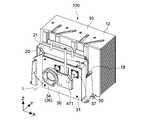
- the image display device 500includes a light source unit 100, an image generation unit 200, a projection unit 400, a housing unit 450, and a sensor mechanism 470.
- the light source unit 100emits emitted light toward the image generation unit 200.
- the image generation unit 200generates an image based on the emitted light emitted from the light source unit 100.
- the projection unit 400projects the image generated by the image generation unit 200 on a screen or the like.
- the housing portion 450has an outer frame portion 451, an intake port 452, and an exhaust port 453.
- the outer frame portion 451is configured to surround the light source unit 100, the image generation unit 200, and the projection unit 400.
- the outer frame portion 451has a substantially rectangular parallelepiped shape, and includes a front surface portion 454, a back surface portion 455, a side surface portion 456, a bottom surface portion 457, and an upper surface portion. In FIG. 1, the upper surface portion is not shown.
- the intake port 452is formed in one of the two side surface portions 456a and 456b of the outer frame portion 451 and sucks the external air.
- the exhaust port 453is formed in the other side surface portion 456 b of the two side surface portions 456 a and 456 b and discharges the air taken in from the intake port 452.
- the intake port 452 and the exhaust port 453are formed in a rectangular shape extending in the front-rear direction (Y direction) from the front surface portion 454 to the back surface portion 455.
- External airis drawn in as cooling air from the air inlet 452 and supplied to the inside of the image display device 500.
- the air that has been cooled by cooling the inside of the image display device 500is exhausted from the exhaust port 453 to the outside.
- a fan mechanism or the likemay be provided in the vicinity of the intake port 452 or in the vicinity of the exhaust port 453 so that the external air efficiently flows in the image display device 500.
- the sensor mechanism 470includes a luminance sensor 471, a light source temperature sensor 472, and an environmental temperature sensor 473.
- the luminance sensor 471is disposed in the vicinity of the light source unit 100, and can detect the intensity (luminance) of the emitted light as the state of the emitted light.
- the specific configuration of the luminance sensor 471is not limited, and any configuration may be employed. Of course, an array sensor composed of a plurality of sensors, or an image sensor such as a CMOS sensor or a CCD sensor may be used.
- detecting the state of lightincludes any method that can detect the state of light to be detected. For example, a method of detecting the state of a part of light included in light to be detected, a method of detecting a state of leaked light of light to be detected, diffracted light and the like are included.
- the light source temperature sensor 472is disposed in the light source unit 100, and can detect the temperature of the light source unit 100.
- the environmental temperature sensor 473is disposed in the vicinity of the intake port 452 and can detect an external temperature. In the present embodiment, the ambient temperature sensor 473 detects the temperature of the external air taken in from the intake port 452 as the external temperature.
- the specific configuration of the light source temperature sensor 472 and the environmental temperature sensor 473is not limited, and any configuration may be employed.
- the luminance sensor 471, the light source temperature sensor 472 and the environmental temperature sensor 473function as a first sensor unit, a second sensor unit, and a third sensor unit, respectively.
- the image display device 500also includes a controller (control unit) 490 that comprehensively controls the operation of the image display device 500 (see FIG. 2).
- the controller 490has a hardware configuration necessary for a computer such as a CPU and a memory (RAM, ROM). Various processes are executed by the CPU loading a control program or the like stored in a memory or the like into the RAM and executing it.
- a programmable logic devicesuch as a field programmable gate array (FPGA) or another device such as an application specific integrated circuit (ASIC) may be used as the controller 490.
- FPGAfield programmable gate array
- ASICapplication specific integrated circuit
- the place where the controller 490 is disposedis not limited, and may be appropriately designed.
- the light source control unit 491is realized by the CPU of the controller 490 executing a predetermined program (see FIG. 2).
- dedicated hardwaresuch as an IC (integrated circuit) may be used as appropriate.
- a storage unitis realized by the memory or the like of the controller 490.
- the storage unitmay be configured by a ROM, an HDD, etc., separately from the controller 490.
- FIG. 2is a schematic view showing a configuration example of the image generation unit 200 and the projection unit 400.
- the light source unit 100, the image generation unit 200, and the projection unit 400are disposed from the back surface 455 to the front surface 454 of the outer frame 451.
- the projection part 400is arrange
- the light source unit 100emits white light W including red light, green light, and blue light as emitted light. Then, the image generation unit 200 generates an image based on the white light W emitted from the light source unit 100.
- the image generation unit 200includes an integrator optical system 210 and an illumination optical system 220.
- the integrator optical system 210includes an integrator element 211, a polarization conversion element 212, and a condenser lens 213.
- the integrator element 211includes a first fly's eye lens 211a having a plurality of microlenses arranged in a two-dimensional manner, and a second microlens having a plurality of microlenses arranged to correspond to the plurality of microlenses one by one. And the fly's-eye lens 211b.
- the white light W incident on the integrator element 211is divided into a plurality of light fluxes by the micro lens of the first fly eye lens 211a, and is imaged on the corresponding micro lenses provided in the second fly eye lens 211b.
- Each of the microlenses of the second fly-eye lens 211 bfunctions as a secondary light source, and emits a plurality of parallel light beams with luminance to the polarization conversion element 212 in the subsequent stage.
- the polarization conversion element 212has a function of aligning the polarization state of incident light incident through the integrator element 211.
- the light having passed through the polarization conversion element 212is emitted to the illumination optical system 220 through the condenser lens 213.
- the integrator optical system 210has a function of adjusting the white light W directed to the illumination optical system 220 into a uniform luminance distribution and adjusting the light into a light having a uniform polarization state.
- the specific configuration of the integrator optical system 210is not limited.
- the illumination optical system 220includes dichroic mirrors 230, 240, 250, 260 and 270, field lenses 280R, 280G and 280B, relay lenses 290 and 300, liquid crystal light valves 310R, 310G and 310B as image forming elements, and dichroic prism 320. It contains.
- the dichroic mirrors 230 to 270selectively reflect colored light in a predetermined wavelength range and transmit light in other wavelength ranges.
- the dichroic mirror 230selectively reflects the green light G1 and the blue light B1 contained in the white light W, and transmits the red light R1 contained in the white light W.
- the dichroic mirror 240selectively reflects the green light G1 reflected by the dichroic mirror 230 and transmits the blue light B1. Thereby, different color lights are separated into different light paths.
- the configuration for separating each color light of RGB, the device to be used, and the likeare not limited.
- the separated red light R1is reflected by the dichroic mirror 250, collimated by the field lens 280R, and then enters the liquid crystal light valve 310R for modulation of red light.
- the green light G1is collimated by the field lens 280G and then enters the liquid crystal light valve 310G for modulation of green light.
- the blue light B 1is reflected by the dichroic mirror 260 through the relay lens 290 and is further reflected by the dichroic mirror 270 through the relay lens 300.
- the blue light B1 reflected by the dichroic mirror 270is collimated by the field lens 280B, and then enters the liquid crystal light valve 310B for blue light modulation.
- the liquid crystal light valves 310R, 310G, and 310Bare electrically connected to a not-shown signal source (for example, a PC or the like) that supplies an image signal including image information.
- the liquid crystal light valves 310R, 310G, and 310Bmodulate the incident light for each pixel based on the supplied image signal of each color to generate a red image, a green image, and a blue image, respectively.
- the modulated light of each color (formed image)is incident on the dichroic prism 320 and synthesized.
- the dichroic prism 320superposes and combines the light of each color that has been incident from three directions, and emits the light toward the projection unit 400.
- the projection unit 400projects the image generated by the image generation unit 200.
- the projection unit 400has a plurality of lenses 410 and the like, and projects the light combined by the dichroic prism 320 onto a screen or the like (not shown). Thus, a full color image is displayed.
- the specific configuration of the projection unit 400is not limited.
- FIG. 3is a perspective view showing a configuration example of the light source unit 100.
- FIG. 4is a view schematically showing an example of the internal configuration of the light source unit 100.
- the light source unit 100includes a light source unit 10, an optical system unit 20, a phosphor unit 30, and a base unit 50 for supporting them.
- the side from which the white light W is emittedis referred to as the front side, and the opposite side is referred to as the rear side.
- the light source unit 10, the optical system unit 20, and the phosphor unit 30are supported by the base 50 so as to be arranged in this order from the rear side to the front side. In FIG. 4, the base unit 50 is not shown.
- the base portion 50has an elongated shape extending in the left-right direction (X direction).
- the base unit 50includes a support mechanism for supporting the light source unit 10, the optical system unit 20, and the phosphor unit 30.
- the specific configuration of the support mechanismis not limited and may be arbitrarily designed.
- FIG. 5is a perspective view showing a configuration example of the light source unit 10.
- the light source unit 10includes two light source blocks 11 aligned in the X direction and a heat sink 12 disposed on the rear side, and these are configured as one unit .
- Each light source block 11has a plurality of laser light sources (laser diodes) 13 driven by supply of current.
- the plurality of laser light sources 13are disposed such that laser light is emitted forward with the front-rear direction as an optical axis direction.
- the plurality of laser light sources 13for example, a blue laser light source capable of oscillating blue laser light B2 having a peak wavelength of light emission intensity in a wavelength range of 400 nm to 500 nm is used.
- the plurality of laser light sources 13correspond to one or more light sources.
- solid state light sourcessuch as LEDs may be used as the one or more light sources.
- LEDsmay be used as the one or more light sources.
- the present technologyis applicable.
- the wavelength range of the light to be emittedis not limited, and may be set arbitrarily.
- FIG. 5in order to explain the position of the light source temperature sensor 472, the illustration of one laser light source 13 is omitted in each light source block 11.
- the fourth laser light source 13 from the top of the rightmost rowis omitted.
- the fourth laser light source 13 from the top of the leftmost rowis omitted.
- the laser light source 13is also disposed at this position.
- the optical system unit 20has a housing portion 21 that forms a closed space S1 and a condensing optical system 22 that is accommodated in the closed space S1.
- a housing portion 21that forms a closed space S1 and a condensing optical system 22 that is accommodated in the closed space S1.
- two entrances 23 through which the blue laser light B2 is incidentare formed.
- An emission port 24 from which the blue laser light B2 condensed by the condensing optical system 22 is formedis formed on the front side surface of the housing unit 21.
- the two entrances 23 and the exit 24are sealed by an optional transparent member made of glass, plastic or the like.
- the entrance 23 and the exit 24are opened, and sealed space S1 may be implement
- the condensing optical system 22has two aspheric mirrors 25 (shown as a plate in the figure) and two plane mirrors 26.
- the aspheric mirror 25reflects and condenses the blue laser light B2 incident on the entrance 23 along the front-rear direction so as to turn it back.
- the flat mirror 26reflects the light reflected by the aspheric mirror 25 toward the exit 24.
- the configuration of the focusing optical system 22is not limited, and any configuration may be employed.
- the phosphor unit 30has a housing 31 forming an enclosed space S2, a wheel 33 accommodated in the enclosed space S2, and an emission lens 34.
- a housing 31On the rear surface of the housing 31, an entrance 35 is formed, into which the blue laser light B2 emitted from the exit 24 of the optical system unit 20 is incident.
- An emission port 36 from which white light W is emittedis formed on the front surface of the housing 31.
- the exit 36is sealed by an exit lens 34.
- a window 37is formed on the front surface of the housing 31.
- the entrance 35 and the window 37are sealed by a transparent member made of glass, plastic or the like.
- the housing portion 31functions as a sealing portion which has a window portion and which forms a sealed space inside.
- the entrance 35is opened and the enclosed space S2 may be realized by being connected to the optical system unit 20.
- a sealed portionis realized by the housing portions 31 and 21.
- the wheel portion 33has a phosphor wheel 38 and a motor 39.
- the phosphor wheel 38is disposed at a position where the blue laser light B2 incident on the entrance 35 is condensed at a predetermined point.
- the motor 39is driven by power supplied via a flexible substrate or the like to rotate the phosphor wheel 38.
- FIG. 6is a diagram for explaining the generation of white light W by the phosphor unit 30.
- the phosphor wheel 38has a disk-shaped substrate 41 for transmitting the blue laser light B2 and a phosphor layer 42 provided on the substrate 41.
- a crystalline membersuch as quartz or sapphire is used, for example.
- the phosphor layer 42contains a phosphor that is excited by the blue laser light B2 emitted by the plurality of laser light sources 13 to emit visible light.
- the phosphor layer 42converts part of the blue laser light B2 into light in a wavelength range (that is, yellow light) including the red wavelength range to the green wavelength range.
- the phosphor layer 42transmits part of the blue laser light B2 as it is. Therefore, light including blue excitation light and yellow fluorescence is emitted from the phosphor layer 42.
- YAGyttrium aluminum garnet
- the type of fluorescent substance, the wavelength range of excitation light, and the wavelength range of visible light generated by excitationare not limited.
- the phosphor layer 42corresponds to a light emitter which is excited by the blue laser light B2 emitted from the plurality of laser light sources 13 to emit visible light.
- the light emitterany other substance different from the phosphor may be used.
- the motor 39is connected to the center of the substrate 41. By driving the motor 39, the phosphor wheel 38 rotates around the rotation axis M.
- the blue light B2is emitted from the light source unit 10.
- the blue laser light B ⁇ b> 2is collected by the optical system unit 20 and irradiated to the phosphor layer 42 through the entrance 35.
- the blue laser light B2is irradiated to the phosphor layer 42 so as to draw a circle relatively as the substrate 41 rotates.
- white light W including the blue laser light B3 transmitted through the phosphor layer 42 and the green light G3 and the red light R3 which are visible light from the phosphor layer 42is emitted.
- the white light Wis emitted along the optical axis L shown in FIGS. 3 and 4 through the emission lens 34 (emission port 36).
- the white light Wcorresponds to light including light from the plurality of laser light sources 13 and visible light from the phosphor layer 42.
- the configuration and method for connecting each unit to the base portion 50 and the configuration and method for connecting each unitare not limited, and any configuration and method such as fitting, adhesion, screw / screw fastening, etc. It may be adopted.
- the luminance sensor 471is disposed at a position facing the window portion 37 formed in the housing portion 31 of the phosphor unit 30. Then, the intensity of the leaked light W ′ emitted from the window 37 is detected.
- the leaked light W ′is leaked white light W including blue laser light B3, green light G3 and red light R3. That is, in the present embodiment, the luminance sensor 471 detects the intensity of the leaked light W ′ of the white light W to be detected.
- the intensity of the leaked light W ′ of the white light W detected by the luminance sensor 471corresponds to the first detection result.
- the position where the luminance sensor 471 is disposedis not limited, and the luminance sensor 471 can be disposed at any position where the intensity of the white light W can be detected.
- the luminance sensor 471may be disposed on the back side (surface opposite to the reflection surface) of the dichroic mirror 250 or 270 in the image generation unit 200. Then, the intensities of the red light R1 and the blue light B1 included in the white light W may be detected.
- a luminance sensor 471may be disposed in the vicinity of the integrator optical system 210, and the intensity of leaked light or the like of the white light W emitted from the polarization conversion element 212 may be detected.
- one light source temperature sensor 472is disposed in each of the two light source blocks 11.
- a light source temperature sensor 472is disposed on the back side of one laser light source 13 of each light source block 11.
- a light source temperature sensor 472is disposed on the back side of the fourth laser light source 13 from the top of the rightmost row.
- a light source temperature sensor 472is disposed on the back side of the fourth laser light source 13 from the top of the left end row. For example, it is possible to mount the light source temperature sensor 472 along with the circuit that drives it on the back surface of the mounting substrate on which the laser light source 13 is mounted.
- the light source temperature sensor 472detects the temperatures of the plurality of laser light sources 13 as the temperature of the light source unit 100.
- positions the light source temperature sensor 472is not limited, You may design arbitrarily.
- the light source temperature sensor 472may be disposed in the enclosed space S1 or S2, and the temperature in the enclosed space S1 or S2 may be detected as the temperature of the light source unit 100.
- the light source temperature detected by the light source temperature sensor 472corresponds to the second detection result.
- the environmental temperature sensor 473is disposed in the vicinity of the intake port 452.
- a cooling structure for appropriately forming an external air flow path of the external airis configured inside the image display device 500.
- the cooling structureis realized by using any member for guiding air such as a duct.
- it is possible to realize an arbitrary cooling structureby forming the positions of the respective mechanisms, the openings for passing air through the respective mechanisms, and the like.
- the environmental temperature sensor 473is disposed in the vicinity of the air inlet 452 on the flow path of the external air formed by the cooling structure. This makes it possible to detect the external temperature with high accuracy.
- the position where the environmental temperature sensor 473 is disposedis not limited, and any position that can detect an external temperature may be selected.
- an environmental temperature sensor 473may be disposed outside the housing 450 and an external temperature may be detected.
- the external temperature detected by the environmental temperature sensor 473corresponds to the third detection result.
- FIG. 7is a schematic graph for describing an outline of control of the light source unit 100 by the light source control unit 491.
- the light source current supplied to the plurality of laser light sources 13is maintained constant.
- the decrease in light source luminance and the increase in light source temperaturecan be regarded as the light source deterioration.
- the light source currentis increased to maintain the light source luminance constant.
- a rise in the light source temperatureoccurs according to the increase in current. If the light source temperature exceeds the upper limit of the rated temperature (denoted as the rated temperature in the drawing), there is a possibility that the luminance may drop sharply or the element may be broken.
- the intensity of leaked light W ′ of the white light Wwhich is the first detection result of the brightness sensor 471 by the light source control unit 491 (hereinafter simply referred to as light source brightness)
- the light source unit 100is controlled based on the light source temperature which is the second detection result by the light source temperature sensor 472. That is, the LD current values supplied to the plurality of laser light sources 13 are controlled based on the light source luminance and the light source temperature.
- the upper limit of the rated temperatureis an example of the upper limit of the operation guarantee temperature.
- a temperature different from the rated temperaturemay be set as the upper limit of the operation guaranteed temperature.
- the graph shown in FIG. 7is a schematic graph.
- the decrease in light source luminance or the increase in light source temperature due to element deterioration of the light sourceis not limited to the case of exhibiting a linear functional behavior.
- the luminancemay decrease or the temperature may increase in various manners depending on the characteristics of the light source, the temperature, and the like.
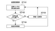
- FIG. 8is a flowchart showing an example of temperature monitoring control.
- the light source temperature detected by the light source temperature sensor 472is acquired (step 101). It is determined whether the light source temperature is higher than a predetermined reference temperature (step 102).
- step 102When the light source temperature is lower than the reference temperature (No in step 102), constant brightness control is performed (step 103). If the light source temperature is higher than the reference temperature (Yes in step 102), temperature suppression control is performed (step 104).
- FIG. 9is a flowchart showing an example of constant brightness control.
- the constant brightness controlis to control the light source unit 100 so that the intensity of the white light W emitted from the light source unit 100 is maintained constant.
- initial values of luminance / temperature / LD current value at the time of luminance adjustmentare stored in a memory or the like of the controller 490 (step 201).
- constantis a concept including “substantially constant”. That is, “constant” is not limited to a completely constant state, but includes a substantially constant state (e.g., a state in which the rate of change is included in a range of ⁇ 10%).
- the LD current valueis controlled such that an image is displayed at a target luminance.
- the light source luminance and the light source temperature detected by the luminance sensor 471 and the light source temperature sensor 472are stored in a memory or the like as initial values. Also, the LD current value at that time is stored as an initial value.
- the brightness adjustmentmay be performed by the user.
- the brightness adjustment modeis selected, and the brightness of the image is controlled by button operation or the like. While the image of the desired brightness is displayed, an operation indicating the completion of adjustment is input.
- the light source luminance, the light source temperature, and the LD current value detected at that timeare stored in the memory as initial values.
- brightness adjustment or the likemay not be performed, and predetermined brightness values, temperatures, and current values may be stored in a memory or the like as initial values of light source brightness, light source temperature, and LD current value.
- the light source luminance detected by the luminance sensor 471is acquired (step 202).
- the acquired light source luminanceis compared with an initial value stored in a memory or the like (step 203).
- the LD current valueis adjusted (step 204). For example, when the detected value is lower than the initial value, the LD current value is increased. Thus, the intensity of the blue laser light B2 emitted from the plurality of laser light sources 13 is increased, and the luminance of the white light W emitted from the light source unit 100 is increased.
- the LD current valueis decreased. As a result, the intensity of the blue laser light B2 emitted from the plurality of laser light sources 13 is reduced, and the luminance of the white light W emitted from the light source unit 100 is reduced.
- control of the LD current valueis completed, the process returns to step 202.
- the LD current valueis not adjusted, and the process returns to step 202.
- a specific threshold value or the like for defining a deviation of a predetermined level or moreis not limited and may be set arbitrarily. Further, the amount of increase or decrease (increase or decrease rate) of the LD current value with respect to the deviation is not limited, and may be set arbitrarily. Typically, for example, the amount of increase or decrease of the LD current value adjusted in one loop may be fixed. Alternatively, the amount of increase or decrease may be appropriately controlled for each loop according to the magnitude of the deviation.
- the temperature suppression control shown in step 104 of FIG. 7is to control the light source unit 100 so that the temperature rise of the light source unit 100 is suppressed.
- the specific method of temperature suppression controlis not limited, and any method capable of suppressing an increase in temperature of the light source unit 100 may be employed.
- the increase rate (increase amount) for increasing the LD current value supplied to the plurality of laser light sources 13it is possible to suppress the increase in the light source temperature.
- FIG. 10is a diagram showing an example of constant brightness control with temperature monitoring.
- the constant brightness control with temperature monitoringis control to keep the brightness of the white light W constant while monitoring the light source temperature so as not to exceed the upper limit of the rated temperature.
- normal luminance constant controlis performed.
- the light source unit 100is controlled such that the intensity of the white light W emitted from the light source unit 100 is maintained constant while suppressing the temperature rise of the light source unit 100 . This control is included in the temperature suppression control.
- initial values of luminance / temperature / LD current value at the time of luminance adjustmentare stored in a memory or the like of the controller 490 (step 301).
- the light source luminance detected by the luminance sensor 471is acquired (step 302).
- the acquired light source luminanceis compared with an initial value stored in a memory or the like (step 303).
- the current LD current valueis set to the target current value (step 304).
- the target current valueis a target current value when changing the LD current value.
- step 304corresponds to maintaining the current LD current value.
- a value obtained by correcting the current LD current valueis set as the target current value (step 305). For example, when the detected value is lower than the initial value, a value obtained by adding a predetermined correction amount ⁇ I to the current LD current value is set as the target current value. If the detected value is higher than the initial value, a value obtained by subtracting the predetermined correction amount ⁇ I from the current LD current value is set as the target current value.
- the specific value of the correction amount ⁇ Iis not limited, and may be set arbitrarily.
- the correction amount ⁇ I for increasing and the correction amount ⁇ I for decreasingmay have the same value or different values.
- the light source temperature detected by the light source temperature sensor 472is acquired (step 306). It is determined whether the light source temperature is higher than a predetermined reference temperature (step 307).
- the LD current value supplied to the laser light source 13is controlled so that the target current value set in step 304 or 305 is obtained (step 308).
- normal brightness constant controlis performed.
- the target current value set in step 304 or 305is corrected. Then, the LD current value supplied to the laser light source 13 is controlled so as to obtain the corrected target current value (step 309).
- the correction of the target current valueis performed such that the intensity of the white light W emitted from the light source unit 100 is maintained constant while suppressing the temperature rise of the light source unit 100.
- FIG. 11is a schematic diagram for explaining an example of the correction of the target current value.
- four threshold values “TL_SaturationLow”, “TL_SaturationCenter”, “TL_SaturationUp”, and “TL_MaxLimit”are set for the light source temperature.
- T_SaturationLowcorresponds to the predetermined reference temperature described with reference to FIGS. 8 to 10.
- TL_SaturationCentercorresponds to a first temperature higher than a predetermined reference temperature.
- T_SaturationUpcorresponds to a second temperature higher than the first temperature.
- TL_MaxLimitcorresponds to a third temperature higher than the second temperature.
- the four threshold valuesare respectively set to values lower than the upper limit of the rated temperature (upper limit of the operating guaranteed temperature) based on the upper limit of the rated temperature (upper limit of the operating guaranteed temperature).
- the increase rate set to increase the LD current value when the light source brightness is lower than the initial value in normal brightness constant controlis taken as a first increase rate.
- the increase rate calculated by adding the predetermined correction amount ⁇ I to the current LD current value for each loopis the first increase rate.
- the rate of increaseis defined as the rate of increase of the LD current value at a predetermined time. That is, the rate of increase is defined by how much the LD current value increases during a predetermined time.
- the loopin the case where the loop is repeated to control the LD current value as in the present embodiment, it can be defined as, for example, the increase rate of the LD current value during the passage of a predetermined number of loops of 2 or more. .
- the increase rateit is also possible to define the increase rate as, for example, the increase rate of the LD current value when the light source luminance is lower than the initial value continuously in a loop of two or more predetermined times. is there.
- a second increase rate lower than the first increase rateis set as an increase rate for increasing the LD current value. That is, the target temperature is appropriately corrected such that the increase rate is lower than the first increase rate calculated by adding the predetermined correction amount ⁇ I to the current LD current value for each loop.
- a method of reducing the increase rate of the LD current valuefor example, as a method of reducing the increase rate of the LD current value when the light source luminance becomes lower than the initial value continuously in a loop of two or more predetermined times. The following methods may be mentioned.
- the current LD current valueis first set to the target current value and supplied to the laser light source 13. Therefore, even if the light source luminance is lower than the initial value, first, the LD current value is maintained, and the improvement of the luminance is basically prohibited.
- the target current value set in step 305is adopted as it is, and the laser light source 13 is Supply current to That is, once every five times, the brightness is improved. This makes it possible to maintain the brightness while monitoring the temperature.
- the number of timesis not limited to five, and other numbers may be employed.
- the LD current valueis controlled to be the target current value. This makes it possible to maintain the luminance.
- the increase of the LD current value supplied to the plurality of laser light sources 13is prohibited.
- the current LD current valueis set to the target current value and supplied to the laser light source 13.
- the light source temperatureis included in the range from “TL_SaturationCenter” to “TL_SaturationUp” three consecutive times.
- a value obtained by subtracting a predetermined correction amount ⁇ I from the current LD current valueis set as the target current value.
- the predetermined correction amount ⁇ Imay be the same as or different from the correction amount ⁇ I used when the light source luminance is higher than the initial value in step 305.
- the LD currentis generated once in three times. The value is lowered. This makes it possible to monitor the temperature and make the luminance constant.
- the number of timesis not limited to three, and other numbers may be employed.
- the reduction rate of the LD current value calculated by lowering the LD current value once every three timesis the first reduction rate.
- the reduction rateis defined as the reduction rate of the LD current value at a predetermined time. That is, the reduction rate is defined by how much the LD current value decreases during a predetermined time.
- the loopis repeated to control the LD current value as in the present embodiment, it is possible to define, for example, the reduction rate of the LD current value during the passage of a predetermined number of loops of 2 or more. .
- the predetermined timeit is possible to set the predetermined time appropriately to define the reduction rate.
- the LD current valueis reduced at a second reduction rate higher than the first reduction rate.
- a method of increasing the reduction ratefor example, a method of increasing the reduction amount with respect to the current LD current value, a method of increasing the reduction number, and the like can be mentioned.
- a value obtained by subtracting a predetermined correction amount ⁇ I from the current LD current valueis set as a target current value for each loop, and a current is supplied to the laser light source 13. That is, the LD current value is forcibly reduced every turn.
- the predetermined correction amount ⁇ Imay be set as appropriate.
- the LD current values supplied to the plurality of laser light sources 13are stopped, and the driving of the laser light sources 13 is stopped. That is, if “TL_MaxLimit” is exceeded, the laser light source 13 is stopped immediately.
- correction of the target temperatureis appropriately performed depending on which temperature zone divided by the four threshold values the current light source temperature is included.
- the LD current valueis controlled while maintaining the luminance constant so that the temperature converges to "TL_SaturationCenter". Since this makes it possible to control the light source current while monitoring the light source temperature, it is possible to prevent the light source temperature from exceeding the upper limit of the rated temperature, and the premature deterioration or destruction of the laser light source 13 is sufficiently achieved. It is possible to prevent.
- the luminance sensor 471 and the light source temperature sensor 472detect the luminance of the white light W and the temperature of the light source unit 100, respectively. By using these detection results, it is possible to control the light source unit 100 with high accuracy.
- the present technologyenables control of the light source unit 100 in consideration of the balance between light source luminance and light source temperature, and also enables high light source luminance to be maintained, for example, within the allowable light source temperature range. Further, the life extension of the image display device 500 is realized, and it is possible to exhibit very high quality.
- the light source temperaturemay rise due to the rise of the environmental temperature (external temperature) as well as the light source deterioration and the current increase. For example, in the use in summer and the use in winter, even when the LD current value is similarly controlled, a difference may occur in the light source temperature.
- the light source temperatureis monitored, it is possible to cope with the increase or decrease of the environmental temperature, and the light source unit 100 can be controlled with extremely high accuracy. That is, it is possible to realize optimal control of the light source unit 100 every season.
- any machine learning algorithm using, for example, DNN (Deep Neural Network) or the likemay be used to execute generation and correction of target current values based on light source luminance and light source temperature.
- DNNDeep Neural Network
- AIArtificial Intelligence
- deep learningdeep learning
- state information on the state of the light source unit 100 based on the light source luminance detected by the luminance sensor 471, the light source temperature detected by the light source temperature sensor 472 and the environmental temperature (external temperature) detected by the environmental temperature sensor 473May be generated.
- the state of aged deteriorationas the state information of the light source unit 100 based on the fluctuation of the light source temperature with respect to the environmental temperature.
- the laser light source 13is driven with the LD current value of the initial value stored in the memory or the like.
- the light source temperature and the environmental temperatureare detected.
- the temperature rise component of the light source deterioration componentas illustrated in FIG. 7A. It is possible to estimate the state of aged deterioration based on the temperature rise.
- the initial value of the environmental temperaturemay be stored in a memory or the like and used appropriately.
- the correction amount ⁇ I used in step 305 of FIG. 10may be appropriately changed according to the state of aged deterioration.
- highly accurate control of the light source unit 100 according to the state of aged deteriorationis realized.
- the light source control unit 491 illustrated in FIG. 2may function as a generation unit, and state information regarding the state of the light source unit 100 may be generated.
- a generation unit that generates state information related to the state of the light source unit 100may be realized separately from the light source control unit 491. Further, as the state of the light source unit 100, information different from the state of aged deterioration may be generated.
- a predetermined machine learning algorithmmay be used to generate state information of the light source unit 100 and to control the light source unit 100 based on the state information.
- the intensity (luminance) of the emitted lightis detected as the state of the emitted light.
- the present inventionis not limited to this, and other parameters such as the chromaticity and the shape of the luminous flux (including the size of the luminous flux (cross-sectional area)) may be detected as the state of the emitted light.
- control of a light source partcontrol of chromaticity, control of luminous flux, etc. may be performed, monitoring light source temperature.
- a sensor unitfor example, a chromaticity sensor or the like
- a sensor unitfor example, a chromaticity sensor or the like
- the present technologycan also adopt the following configuration.
- a light source unitcapable of emitting emitted light;
- a first sensor unitcapable of detecting the state of the emitted light;
- a second sensor unitcapable of detecting the temperature of the light source unit;
- a light source control unitcapable of controlling the light source unit based on a first detection result by the first sensor unit and a second detection result by the second sensor unit;
- the image display devicecontrols the light source unit such that the intensity of the emitted light emitted from the light source unit is maintained constant when the second detection result is lower than a predetermined reference temperature.
- the image display devicecontrols the light source unit such that an increase in temperature of the light source unit is suppressed when the second detection result is higher than a predetermined reference temperature.
- the image display devicecontrols the light source unit such that an increase in temperature of the light source unit is suppressed when the second detection result is higher than a predetermined reference temperature.
- the light source control unitsuppresses the increase in the temperature of the light source unit and makes the intensity of the emitted light emitted from the light source unit constant.
- An image display apparatus that controls the light source unitto be maintained.
- the image display deviceincludes one or more light sources driven by supplying an electric current.
- the second sensor unitdetects the temperature of the one or more light sources as the temperature of the light source unit,
- the light source control unitcontrols current supplied to the one or more light sources.
- the image display device(8) The image display device according to (7), wherein The light source control unit sets a first increase rate as an increase rate for increasing the current supplied to the one or more light sources when the second detection result is lower than a predetermined reference temperature.
- Image display device(9) The image display device according to (8), wherein The light source control unit is configured to increase the current supplied to the one or more light sources when the second detection result is included in a range from a predetermined reference temperature to the first temperature. Setting a second increase rate lower than the first increase rate.
- the light source control unitmay be configured to set the one or more at least by the first reduction rate.
- An image displaythat reduces the current supplied to the light source.
- the light source control unitmay be configured to have a higher reduction rate than the first reduction rate.
- An image display apparatuswhich reduces the current supplied to the one or more light sources by a reduction rate of 2.
- the image display device(12) The image display device according to (11), wherein The light source control unit stops the supply of current to the one or more light sources when the second detection result is higher than the third temperature.
- the image display device(13) The image display device according to any one of (1) to (12), wherein The predetermined reference temperature is set to a temperature lower than the upper limit of the operation guarantee temperature based on the upper limit of the operation guarantee temperature of the light source unit.
- the image display deviceaccording to any one of (1) to (14), further comprising: A third sensor unit capable of detecting an external temperature; A state regarding the state of the light source unit based on a first detection result by the first sensor unit, a second detection result by the second sensor unit, and a third detection result by the third sensor unit
- An image display apparatuscomprising: a generation unit that generates information.
- the image display devicefurther comprising It has a housing unit having an intake port for sucking in external air, An image display apparatus, wherein the third sensor unit is disposed in the vicinity of the intake port and detects the temperature of the external air sucked from the intake port as the external temperature.
- the image display deviceaccording to (15) or (16), wherein The light source control unit controls the light source unit based on the generated state information.
- the image display apparatusaccording to any one of (1) to (17), further comprising: An image generation unit configured to generate an image based on the emitted light emitted from the light source unit; An image display apparatus comprising: a projection unit configured to project an image generated by the image generation unit;
- Laser light source 100Light source unit 200: Image generation unit 400: Projection unit 450: Housing unit 452: Intake port 470: Sensor mechanism 471: Brightness sensor 472: Light source temperature Sensor 473: Environmental temperature sensor 490: Controller 491: Light source control unit 500: Image display device
Landscapes
- Engineering & Computer Science (AREA)
- Multimedia (AREA)
- Signal Processing (AREA)
- Physics & Mathematics (AREA)
- General Physics & Mathematics (AREA)
- Optics & Photonics (AREA)
- Projection Apparatus (AREA)
- Transforming Electric Information Into Light Information (AREA)
Abstract
Description
Translated fromJapanese本技術は、プロジェクタ等の画像表示装置に関する。The present technology relates to an image display device such as a projector.
従来からプロジェクタ等の画像表示装置が広く用いられている。例えば光源からの光が液晶素子等の光変調素子により変調され、その変調光がスクリーン等に投影されることで画像が表示される。光源としては、水銀ランプ、キセノンランプ、LED(Light Emitting Diode)やLD(Laser Diode)等が用いられる。このうちLEDやLD等の固体光源は寿命が長く従来のようなランプ交換が不要であり、また電源を入れて即時に点灯するといった利点を有する。Conventionally, an image display apparatus such as a projector has been widely used. For example, light from a light source is modulated by a light modulation element such as a liquid crystal element, and the modulated light is projected on a screen or the like to display an image. As a light source, a mercury lamp, a xenon lamp, an LED (Light Emitting Diode), an LD (Laser Diode) or the like is used. Among them, solid-state light sources such as LEDs and LDs have a long life and do not require lamp replacement as in the prior art, and also have the advantage of turning on the power and turning on immediately.
特許文献1には、環境温度センサ、光源温度センサ、及び光学系温度センサが備えられた画像表示装置が記載されている。環境温度センサは、吸気口の近傍に配置され外部温度を測定可能である。光源温度センサはレーザ光源の温度を測定可能であり、光学系温度センサは照明光学系の温度を測定可能である。各温度センサにより測定された温度に基づいて画像表示装置を適宜制御することで、装置の長寿命化が実現されている(特許文献1の明細書段落[0102][0103][0113][0124][0131]図1等)。Patent Document 1 describes an image display device provided with an environmental temperature sensor, a light source temperature sensor, and an optical system temperature sensor. The environmental temperature sensor is disposed in the vicinity of the air intake and can measure an external temperature. The light source temperature sensor can measure the temperature of the laser light source, and the optical system temperature sensor can measure the temperature of the illumination optical system. By appropriately controlling the image display device based on the temperature measured by each temperature sensor, the device life extension is realized (the specification paragraph [0102] [0103] [0103] [0113] [0124]. [0131] Figure 1 etc.).
プロジェクタ等の画像表示装置では、光源の経時変化等により輝度が低下してしまうことがある。このような問題を防止するために光源を高精度に制御することを可能とする技術が求められている。In an image display apparatus such as a projector, the luminance may be reduced due to the change with time of the light source or the like. In order to prevent such a problem, there is a need for a technology that can control the light source with high accuracy.
以上のような事情に鑑み、本技術の目的は、光源を高精度に制御することが可能な画像表示装置を提供することにある。In view of the above circumstances, an object of the present technology is to provide an image display device capable of controlling a light source with high accuracy.
上記目的を達成するため、本技術の一形態に係る画像表示装置は、光源部と、第1のセンサ部と、第2のセンサ部と、光源制御部とを具備する。
前記光源部は、出射光を出射可能である。
前記第1のセンサ部は、前記出射光の状態を検出可能である。
前記第2のセンサ部は、前記光源部の温度を検出可能である。
前記光源制御部は、前記第1のセンサ部による第1の検出結果、及び前記第2のセンサ部による第2の検出結果に基づいて、前記光源部を制御可能である。In order to achieve the above object, an image display device according to an embodiment of the present technology includes a light source unit, a first sensor unit, a second sensor unit, and a light source control unit.
The light source unit can emit outgoing light.
The first sensor unit can detect the state of the outgoing light.
The second sensor unit can detect the temperature of the light source unit.
The light source control unit can control the light source unit based on a first detection result by the first sensor unit and a second detection result by the second sensor unit.
この画像表示装置では、第1及び第2のセンサ部により、出射光の状態及び光源部の温度がそれぞれ検出される。これらの検出結果を利用することで、光源部を高精度に制御することが可能となる。In this image display device, the state of the emitted light and the temperature of the light source unit are respectively detected by the first and second sensor units. By using these detection results, it is possible to control the light source unit with high accuracy.
前記光源制御部は、前記第2の検出結果が所定の基準温度よりも低い場合に、前記光源部から出射される前記出射光の強度が一定に維持されるように、前記光源部を制御してもよい。The light source control unit controls the light source unit so that the intensity of the emitted light emitted from the light source unit is maintained constant when the second detection result is lower than a predetermined reference temperature. May be
前記光源制御部は、前記第2の検出結果が所定の基準温度よりも高い場合に、前記光源部の温度の上昇が抑制されるように、前記光源部を制御してもよい。The light source control unit may control the light source unit such that an increase in temperature of the light source unit is suppressed when the second detection result is higher than a predetermined reference temperature.
前記光源制御部は、前記第2の検出結果が所定の基準温度よりも高い場合に、前記光源部の温度の上昇を抑制しつつ、前記光源部から出射される前記出射光の強度が一定に維持されるように、前記光源部を制御してもよい。When the second detection result is higher than a predetermined reference temperature, the light source control unit suppresses the increase in the temperature of the light source unit and makes the intensity of the emitted light emitted from the light source unit constant. The light source unit may be controlled to be maintained.
前記光源部は、電流が供給されることにより駆動する1以上の光源を有してもよい。この場合、前記第2のセンサ部は、前記1以上の光源の温度を前記光源部の温度として検出してもよい。また前記光源制御部は、前記1以上の光源に供給される電流を制御してもよい。The light source unit may have one or more light sources driven by being supplied with an electric current. In this case, the second sensor unit may detect the temperature of the one or more light sources as the temperature of the light source unit. The light source control unit may control current supplied to the one or more light sources.
前記光源制御部は、前記第2の検出結果が所定の基準温度よりも高い場合に、前記1以上の光源に供給される電流を増加させるための増加率を制御してもよい。The light source control unit may control an increase rate for increasing the current supplied to the one or more light sources when the second detection result is higher than a predetermined reference temperature.
前記光源制御部は、前記第2の検出結果が前記所定の基準温度よりも高い第1の温度よりも高い場合に、前記1以上の光源に供給される電流の増加を禁止してもよい。The light source control unit may prohibit an increase in the current supplied to the one or more light sources when the second detection result is higher than a first temperature higher than the predetermined reference temperature.
前記光源制御部は、前記第2の検出結果が所定の基準温度よりも低い場合に、前記1以上の光源に供給される電流を増加させるための増加率として、第1の増加率を設定してもよい。The light source control unit sets a first increase rate as an increase rate for increasing the current supplied to the one or more light sources when the second detection result is lower than a predetermined reference temperature. May be
前記光源制御部は、前記第2の検出結果が所定の基準温度から前記第1の温度までの範囲に含まれる場合に、前記1以上の光源に供給される電流を増加させるための増加率として、前記第1の増加率よりも低い第2の増加率を設定してもよい。The light source control unit is configured to increase the current supplied to the one or more light sources when the second detection result is included in a range from a predetermined reference temperature to the first temperature. And a second increase rate lower than the first increase rate may be set.
前記光源制御部は、前記第2の検出結果が前記第1の温度から前記第1の温度よりも高い第2の温度までの範囲に含まれる場合に、第1の減少率により前記1以上の光源に供給される電流を減少させてもよい。When the second detection result is included in a range from the first temperature to a second temperature higher than the first temperature, the light source control unit may be configured to set the one or more at least by the first reduction rate. The current supplied to the light source may be reduced.
前記光源制御部は、前記第2の検出結果が前記第2の温度から前記第2の温度よりも高い第3の温度までの範囲に含まれる場合に、前記第1の減少率よりも高い第2の減少率により前記1以上の光源に供給される電流を減少させてもよい。When the second detection result is included in a range from the second temperature to a third temperature that is higher than the second temperature, the light source control unit may be configured to have a higher reduction rate than the first reduction rate. The reduction rate of 2 may reduce the current supplied to the one or more light sources.
前記光源制御部は、前記第2の検出結果が前記第3の温度よりも高い場合に、前記1以上の光源への電流の供給を停止してもよい。The light source control unit may stop the supply of current to the one or more light sources when the second detection result is higher than the third temperature.
前記所定の基準温度は、前記光源部の動作保証温度の上限を基準に、前記動作保証温度の上限よりも低い温度に設定されてもよい。The predetermined reference temperature may be set to a temperature lower than the upper limit of the operation guarantee temperature based on the upper limit of the operation guarantee temperature of the light source unit.
前記第1の温度、前記第2の温度、及び前記第3の温度の各々は、前記光源部の動作保証温度の上限を基準に、前記動作保証温度の上限よりも低い温度に設定されてもよい。Each of the first temperature, the second temperature, and the third temperature may be set to a temperature lower than the upper limit of the operation guarantee temperature based on the upper limit of the operation guarantee temperature of the light source unit Good.
前記画像表示装置は、さらに、第3のセンサ部と、生成部とを具備してもよい。
前記第3のセンサ部は、外部の温度を検出可能である。
前記生成部は、前記第1のセンサ部による第1の検出結果、前記第2のセンサ部による第2の検出結果、及び前記第3のセンサ部による第3の検出結果に基づいて、前記光源部の状態に関する状態情報を生成してもよい。The image display device may further include a third sensor unit and a generation unit.
The third sensor unit can detect an external temperature.
The generation unit is configured to generate the light source based on a first detection result by the first sensor unit, a second detection result by the second sensor unit, and a third detection result by the third sensor unit. State information on the state of the unit may be generated.
前記画像表示装置は、さらに、外部の空気を吸入する吸気口を有する筐体部を具備してもよい。この場合、前記第3のセンサ部は、前記吸気口の近傍に配置され前記吸気口から吸入される前記外部の空気の温度を、前記外部の温度として検出してもよい。The image display apparatus may further include a housing unit having an air inlet for drawing in external air. In this case, the third sensor unit may detect the temperature of the external air disposed in the vicinity of the intake port and drawn from the intake port as the external temperature.
前記光源制御部は、前記生成された状態情報に基づいて、前記光源部を制御してもよい。The light source control unit may control the light source unit based on the generated state information.
前記画像表示装置は、さらに、画像生成部と、投射部とを具備してもよい。
前記画像生成部は、前記光源部から出射された前記出射光に基づいて画像を生成する。
前記投射部は、前記画像生成部により生成された画像を投射する。The image display device may further include an image generation unit and a projection unit.
The image generation unit generates an image based on the emitted light emitted from the light source unit.
The projection unit projects an image generated by the image generation unit.
以上のように、本技術によれば、光源を高精度に制御することが可能となる。なお、ここに記載された効果は必ずしも限定されるものではなく、本開示中に記載されたいずれかの効果であってもよい。As described above, according to the present technology, it is possible to control the light source with high accuracy. In addition, the effect described here is not necessarily limited, and may be any effect described in the present disclosure.
以下、本技術に係る実施形態を、図面を参照しながら説明する。Hereinafter, embodiments according to the present technology will be described with reference to the drawings.
[画像表示装置]
図1は、本技術の一実施形態に係る画像表示装置の構成例を示す概略図である。以下の説明では、画像表示装置500の左右方向、前後方向、及び高さ方向を、X方向、Y方向及びZ方向として説明を行う。もちろんこのような方向の設定に限定される訳ではない。[Image display device]
FIG. 1 is a schematic view showing a configuration example of an image display device according to an embodiment of the present technology. In the following description, the horizontal direction, the front-rear direction, and the height direction of the
画像表示装置500は、例えばプレゼンテーション用、もしくはデジタルシネマ用のプロジェクタとして用いられる。その他の用途に用いられる任意の画像表示装置に、以下に説明する本技術は適用可能である。The
画像表示装置500は、光源部100と、画像生成部200と、投射部400と、筐体部450と、センサ機構470とを有する。The
光源部100は、画像生成部200に向けて出射光を出射する。画像生成部200は、光源部100から出射された出射光に基づいて画像を生成する。投射部400は、画像生成部200により生成された画像をスクリーン等に投射する。The
筐体部450は、外枠部451と、吸気口452と、排気口453とを有する。外枠部451は、光源部100、画像生成部200、及び投射部400を囲むように構成される。外枠部451は略直方体形状を有し、前面部454、背面部455、側面部456、底面部457、及び上面部を有する。なお図1では、上面部の図示が省略されている。The housing portion 450 has an
吸気口452は、外枠部451の2つの側面部456a及び456bのうち一方の側面部456aに形成され、外部の空気を吸入する。排気口453は、2つの側面部456a及び456bのうち他方の側面部456bに形成され、吸気口452から吸入された空気を排出する。本実施形態では、吸気口452及び排気口453は、前面部454から背面部455に向かう前後方向(Y方向)に延在する長方形状に形成される。The
吸気口452から外部の空気が冷却風として吸入され、画像表示装置500の内部に供給される。画像表示装置500の内部を冷却して暖かくなった空気は、排気口453から外部に排出される。外部の空気が効率よく画像表示装置500内を流れるように、吸気口452の近傍や排気口453の近傍にファン機構等が設けられてもよい。External air is drawn in as cooling air from the
センサ機構470は、輝度センサ471と、光源温度センサ472と、環境温度センサ473とを有する。The
輝度センサ471は、光源部100の近傍に配置され、出射光の状態として、出射光の強度(輝度)を検出することが可能である。輝度センサ471の具体的な構成は限定されず、任意の構成が採用されてよい。もちろん、複数のセンサにより構成されたアレイセンサや、CMOSセンサやCCDセンサ等のイメージセンサが用いられてもよい。The
なお光の状態を検出するとは、検出対象となる光の状態を検出可能な任意の方法を含む。例えば検出対象となる光に含まれる一部の光の状態を検出する方法や、検出対象となる光の漏れ光や回折光等の状態を検出する方法等も含まれる。Note that detecting the state of light includes any method that can detect the state of light to be detected. For example, a method of detecting the state of a part of light included in light to be detected, a method of detecting a state of leaked light of light to be detected, diffracted light and the like are included.
光源温度センサ472は、光源部100内に配置され、光源部100の温度を検出することが可能である。環境温度センサ473は、吸気口452の近傍に配置され、外部の温度を検出することが可能である。本実施形態では、環境温度センサ473により、吸気口452から吸入される外部の空気の温度が、外部の温度として検出される。The light
光源温度センサ472及び環境温度センサ473の具体的な構成は限定されず、任意の構成が採用されてよい。本実施形態において、輝度センサ471、光源温度センサ472、及び環境温度センサ473は、第1のセンサ部、第2のセンサ部、及び第3のセンサ部としてそれぞれ機能する。The specific configuration of the light
また画像表示装置500は、画像表示装置500の動作を包括的に制御するコントローラ(制御部)490を有する(図2参照)。コントローラ490は、例えばCPUやメモリ(RAM、ROM)等のコンピュータに必要なハードウェア構成を有する。CPUがメモリ等に記憶されている制御プログラム等をRAMにロードして実行することにより、種々の処理が実行される。The
コントローラ490として、例えばFPGA(Field Programmable Gate Array)等のPLD(Programmable Logic Device)、その他ASIC(Application Specific IntegratedCircuit)等のデバイスが用いられてもよい。またコントローラ490が配置される箇所等も限定されず、適宜設計されてよい。For example, a programmable logic device (PLD) such as a field programmable gate array (FPGA) or another device such as an application specific integrated circuit (ASIC) may be used as the
本実施形態では、コントローラ490のCPUが所定のプログラムを実行することにより、光源制御部491が実現される(図2参照)。光源制御部491を実現するために、IC(集積回路)等の専用のハードウェアが適宜用いられてもよい。また本実施形態では、コントローラ490のメモリ等により記憶部が実現される。もちろんコントローラ490とは別に、ROMやHDD等により記憶部が構成されてもよい。In the present embodiment, the light
図2は、画像生成部200及び投射部400の構成例を示す概略図である。図2に示すように、外枠部451の背面部455から前面部454にかけて光源部100、画像生成部200、及び投射部400が配置される。投射部400は、その出射面401が前面部454から外部側に突出するように配置される。FIG. 2 is a schematic view showing a configuration example of the
本実施形態では、光源部100により、出射光として、赤色光、緑色光、及び青色光を含む白色光Wが出射される。そして画像生成部200により、光源部100から出射された白色光Wに基づいて画像が生成される。In the present embodiment, the
画像生成部200は、インテグレータ光学系210と、照明光学系220とを有する。インテグレータ光学系210は、インテグレータ素子211と、偏光変換素子212と、集光レンズ213とを有する。The
インテグレータ素子211は、二次元に配列された複数のマイクロレンズを有する第1のフライアイレンズ211aと、その複数のマイクロレンズに一つずつ対応するように配列された複数のマイクロレンズを有する第2のフライアイレンズ211bとを有する。The
インテグレータ素子211に入射した白色光Wは、第1のフライアイレンズ211aのマイクロレンズによって複数の光束に分割され、第2のフライアイレンズ211bに設けられた対応するマイクロレンズにそれぞれ結像される。第2のフライアイレンズ211bのマイクロレンズのそれぞれが二次光源として機能し、輝度がった複数の平行光を、後段の偏光変換素子212に出射する。The white light W incident on the
偏光変換素子212は、インテグレータ素子211を介して入射する入射光の偏光状態を揃える機能を有する。偏光変換素子212を通った光は、集光レンズ213を介して照明光学系220に出射される。The
インテグレータ光学系210は、全体として、照明光学系220へ向かう白色光Wを均一な輝度分布に整え、偏光状態の揃った光に調整する機能を有する。インテグレータ光学系210の具体的な構成は限定されない。As a whole, the integrator
照明光学系220は、ダイクロイックミラー230、240、250、260及び270、フィールドレンズ280R、280G及び280B、リレーレンズ290及び300、画像生成素子としての液晶ライトバルブ310R、310G及び310B、ダイクロイックプリズム320を含んでいる。The illumination optical system 220 includes
ダイクロイックミラー230~270は、所定の波長域の色光を選択的に反射し、それ以外の波長域の光を透過させる性質を有する。ダイクロイックミラー230は、白色光Wに含まれる緑色光G1及び青色光B1を選択的に反射し、白色光Wに含まれる赤色光R1を透過させる。The dichroic mirrors 230 to 270 selectively reflect colored light in a predetermined wavelength range and transmit light in other wavelength ranges. The
ダイクロイックミラー240は、ダイクロイックミラー230により反射された緑色光G1を選択的に反射し、青色光B1を透過させる。これにより異なる色光は、それぞれ異なる光路に分離される。なおRGBの各色光を分離するための構成や、用いられるデバイス等は限定されない。The
分離された赤色光R1は、ダイクロイックミラー250により反射され、フィールドレンズ280Rにより平行化された後、赤色光の変調用の液晶ライトバルブ310Rに入射する。緑色光G1は、フィールドレンズ280Gにより平行化された後、緑色光の変調用の液晶ライトバルブ310Gに入射する。The separated red light R1 is reflected by the
青色光B1はリレーレンズ290を通ってダイクロイックミラー260によって反射され、さらにリレーレンズ300を通ってダイクロイックミラー270によって反射される。ダイクロイックミラー270により反射された青色光B1は、フィールドレンズ280Bにより平行化された後、青色光の変調用の液晶ライトバルブ310Bに入射する。The blue light B 1 is reflected by the
液晶ライトバルブ310R、310G及び310Bは、画像情報を含んだ画像信号を供給する図示しない信号源(例えばPC等)と電気的に接続されている。液晶ライトバルブ310R、310G及び310Bは、供給される各色の画像信号に基づき、入射光を画素毎に変調し、それぞれ赤色画像、緑色画像及び青色画像を生成する。変調された各色の光(形成された画像)は、ダイクロイックプリズム320に入射して合成される。ダイクロイックプリズム320は、3つの方向から入射した各色の光を重ね合わせて合成し、投射部400に向けて出射する。The liquid crystal
投射部400は、画像生成部200により生成された画像を投射する。投射部400は、複数のレンズ410等を有し、ダイクロイックプリズム320によって合成された光を図示しないスクリーン等に投射する。これによりフルカラーの画像が表示される。投射部400の具体的な構成は限定されない。The
図3は、光源部100の構成例を示す斜視図である。図4は、光源部100の内部の構成例を模式的に示す図である。光源部100は、光源ユニット10と、光学系ユニット20と、蛍光体ユニット30と、これらを支持するベース部50とを有する。FIG. 3 is a perspective view showing a configuration example of the
白色光Wが出射される側を前方側とし、その反対側を後方側とする。光源ユニット10、光学系ユニット20、及び蛍光体ユニット30は、後方側から前方側にかけて、この順で並ぶようにベース部50に支持される。なお図4では、ベース部50の図示は省略されている。The side from which the white light W is emitted is referred to as the front side, and the opposite side is referred to as the rear side. The
ベース部50は、左右方向(X方向)に延在する細長い形状を有する。ベース部50には、光源ユニット10、光学系ユニット20、及び蛍光体ユニット30を支持するための支持機構が構成される。支持機構の具体的な構成は限定されず、任意に設計されてよい。The
図5は、光源ユニット10の構成例を示す斜視図である。図4及び図5に示すように、光源ユニット10は、X方向に並ぶ2つの光源ブロック11と、その後方側に配置されたヒートシンク12とを有し、これらが1つのユニットとして構成されている。FIG. 5 is a perspective view showing a configuration example of the
各光源ブロック11は、電流が供給されることにより駆動する複数のレーザ光源(レーザダイオード)13を有する。複数のレーザ光源13は、前後方向を光軸方向として、前方側に向けてレーザ光が出射されるように配置される。Each
本実施形態では、複数のレーザ光源13として、例えば400nm-500nmの波長範囲内に発光強度のピーク波長を有する青色レーザ光B2を発振可能な青色レーザ光源が用いられる。本実施形態において、複数のレーザ光源13は、1以上の光源に相当する。In the present embodiment, as the plurality of
1以上の光源として、LED等の他の固体光源が用いられてもよい。また水銀ランプ、キセノンランプ等が用いられる場合でも、本技術は適用可能である。また出射される光の波長域も限定されず、任意に設定されてよい。Other solid state light sources such as LEDs may be used as the one or more light sources. In addition, even when a mercury lamp, a xenon lamp or the like is used, the present technology is applicable. Moreover, the wavelength range of the light to be emitted is not limited, and may be set arbitrarily.
なお図5では、光源温度センサ472の位置を説明するために、各光源ブロック11において、1つのレーザ光源13の図示が省略されている。図中左側の光源ブロック11では、右端の列の上から4個目のレーザ光源13の図示が省略されている。図中右側の光源ブロック11では、左端の列の上から4個目のレーザ光源13の図示が省略されている。当然のことながら、この位置にも、レーザ光源13が配置される。In FIG. 5, in order to explain the position of the light
図4に示すように、光学系ユニット20は、密閉空間S1を形成する筐体部21と、密閉空間S1内に収容される集光光学系22とを有する。筐体部21の後方側の面の、光源ブロック11に対向する位置には、青色レーザ光B2が入射する2つの入射口23が形成される。筐体部21の前方側の面には、集光光学系22により集光された青色レーザ光B2が出射される出射口24が形成される。As shown in FIG. 4, the
2つの入射口23、及び出射口24は、ガラスやプラスチック等からなる任意の透明部材により密閉されている。なお入射口23、及び出射口24が開口しており、光源ユニット10及び蛍光体ユニット30と接続されることで、密閉空間S1が実現されてもよい。The two
集光光学系22は、2つの非球面ミラー25(図中では板状に図示されている)と、2つの平面ミラー26とを有する。非球面ミラー25は、前後方向に沿って入射口23に入射する青色レーザ光B2を折り返すように反射して集光する。平面ミラー26は、非球面ミラー25により反射された光を、出射口24に向けて反射する。集光光学系22の構成は限定されず、任意の構成が採用されてよい。The condensing
蛍光体ユニット30は、密閉空間S2を形成する筐体部31と、密閉空間S2内に収容されるホイール部33と、出射レンズ34とを有する。筐体部31の後方側の面には、光学系ユニット20の出射口24から出射された青色レーザ光B2が入射する入射口35が形成される。筐体部31の前方側の面には、白色光Wが出射される出射口36が形成される。出射口36は、出射レンズ34により密閉されている。The
また筐体部31の前方側の面には、窓部37が形成されている。入射口35、及び窓部37は、ガラスやプラスチック等からなる透明部材により密閉されている。本実施形態において、筐体部31は、窓部を有し内部に密閉された空間を形成する密閉部として機能する。なお入射口35が開口しており、光学系ユニット20と接続されることで、密閉空間S2が実現されてもよい。この場合、筐体部31及び21により、密閉部が実現される。A
ホイール部33は、蛍光体ホイール38と、モータ39とを有する。蛍光体ホイール38は、入射口35に入射する青色レーザ光B2が所定のポイントに集光する位置に配置される。モータ39は、フレキシブル基板等を介して供給される電力により駆動し、蛍光体ホイール38を回転させる。The
図6は、蛍光体ユニット30による白色光Wの生成を説明するための図である。蛍光体ホイール38は、青色レーザ光B2を透過させる円盤形状の基板41と、その基板41上に設けられた蛍光体層42とを有する。基板41としては、例えば水晶やサファイア等の結晶性部材が用いられる。FIG. 6 is a diagram for explaining the generation of white light W by the
蛍光体層42は、複数のレーザ光源13により出射される青色レーザ光B2によって励起されて可視光を発する蛍光物質を含んでいる。本実施形態では、蛍光体層42により、青色レーザ光B2の一部が、赤色波長域から緑色波長域までを含む波長域の光(すなわち黄色光)に変換される。また蛍光体層42は、青色レーザ光B2の一部をそのまま透過させる。従って蛍光体層42からは、青色の励起光と黄色の蛍光とを含む光が出射される。The
蛍光体層42に含まれる蛍光物質としては、例えばYAG(イットリウム・アルミニウム・ガーネット)系蛍光体が用いられる。なお、蛍光物質の種類、励起光の波長域、及び励起により発生される可視光の波長域は限定されない。As a fluorescent substance contained in the
本実施形態において、蛍光体層42は、複数のレーザ光源13から出射される青色レーザ光B2により励起されて可視光を発する発光体に相当する。発光体として、蛍光体とは異なる他の任意の物質が用いられてもよい。In the present embodiment, the
モータ39は、基板41の中心に接続される。モータ39が駆動することで、蛍光体ホイール38が、回転軸Mを中心として回転する。The
モータ39により基板41が回転されている状態で、光源ユニット10から青色レーザ光B2が出射される。青色レーザ光B2は、光学系ユニット20により集光され、入射口35を介して蛍光体層42に照射される。青色レーザ光B2は、基板41の回転に合わせて、相対的に円を描くように蛍光体層42に照射される。While the
これにより図6に示すように、蛍光体層42を透過した青色レーザ光B3と、蛍光体層42からの可視光である緑色光G3及び赤色光R3とを含む白色光Wが出射される。白色光Wは、出射レンズ34(出射口36)を介して、図3及び図4に示す光軸Lに沿って出射される。本実施形態において、白色光Wは、複数のレーザ光源13からの光と蛍光体層42からの可視光とを含む光に相当する。Thereby, as shown in FIG. 6, white light W including the blue laser light B3 transmitted through the
なお各ユニットのベース部50への接続するための構成や方法、各ユニット同士を接続するための構成や方法は限定されず、嵌合、接着、ネジ/ビス留め等、任意の構成及び方法が採用されてよい。The configuration and method for connecting each unit to the
[センサ機構]
図3、図4、及び図6に示すように、輝度センサ471は、蛍光体ユニット30の筐体部31に形成された窓部37に対向する位置に配置される。そして窓部37から出射される漏れ光W'の強度が検出される。漏れ光W'は、青色レーザ光B3、緑色光G3及び赤色光R3を含む、白色光Wの漏れ光である。すなわち本実施形態では、輝度センサ471により、検出対象である白色光Wの漏れ光W'の強度が検出される。輝度センサ471により検出される白色光Wの漏れ光W'の強度は、第1の検出結果に相当する。[Sensor mechanism]
As shown in FIG. 3, FIG. 4 and FIG. 6, the
なお輝度センサ471が配置される位置は限定されず、白色光Wの強度を検出可能な任意の位置に輝度センサ471を配置することが可能である。例えば画像生成部200内のダイクロイックミラー250や270の背面側(反射面とは反対側の面)に輝度センサ471が配置されてもよい。そして白色光Wに含まれる赤色光R1や青色光B1の強度が検出されてもよい。またインテグレータ光学系210の近傍に輝度センサ471が配置され、偏光変換素子212から出射される白色光Wの漏れ光等の強度が検出されてもよい。The position where the
図5に示すように、光源温度センサ472は、2つの光源ブロック11に、1つずつ配置される。本実施形態では、各光源ブロック11の1つのレーザ光源13の背面側に、光源温度センサ472が配置される。As shown in FIG. 5, one light
図中左側の光源ブロック11では、右端の列の上から4個目のレーザ光源13の背面側に、光源温度センサ472が配置される。図中右側の光源ブロック11では、左端の列の上から4個目のレーザ光源13の背面側に、光源温度センサ472が配置される。例えばレーザ光源13を実装する実装基板の裏側の面に、光源温度センサ472を、それを駆動させる回路とともに実装することが可能である。In the
本実施形態では、光源温度センサ472により、光源部100の温度として、複数のレーザ光源13の温度が検出される。なお光源温度センサ472を配置する位置は限定されず、任意に設計されてよい。例えば密閉空間S1やS2内に光源温度センサ472が配置され、密閉空間S1やS2内の温度が、光源部100の温度として検出されてもよい。光源温度センサ472により検出される光源温度は、第2の検出結果に相当する。In the present embodiment, the light
図1に示すように、環境温度センサ473は、吸気口452の近傍に配置される。画像表示装置500の内部には、外部の空気の外部の空気の流路を適正に形成するための冷却構造が構成されている。例えば冷却構造は、ダクト等の空気を誘導するための任意の部材を用いることで実現される。また各機構の位置や、各機構に空気を通す開口や孔等を形成すること等により、任意の冷却構造を実現することが可能である。As shown in FIG. 1, the
環境温度センサ473は、吸気口452の近傍の、冷却構造により形成された外部の空気の流路上に配置される。これにより外部の温度を高い精度で検出することが可能である。もちろん環境温度センサ473が配置される位置は限定されず、外部の温度を検出可能な任意の位置が選択されてよい。例えば筐体部450の外側に環境温度センサ473が配置され、外部の温度が検出されてもよい。環境温度センサ473により検出される外部温度は、第3の検出結果に相当する。The
[光源部の制御]
図7は、光源制御部491による光源部100の制御の概要を説明するための模式的なグラフである。図7Aに示すように、複数のレーザ光源13に供給される光源電流を一定に維持する。そうすると、レーザ光源13の経年劣化により、光源輝度が低下するとともに、光源温度が上昇する。例えば光源輝度の低下分、及び光源温度の上昇分を、光源劣化分と見做すことが可能である。[Control of light source unit]
FIG. 7 is a schematic graph for describing an outline of control of the
そこで本実施形態では、図7Bに示すように、光源電流を増加させることで、光源輝度を一定に維持させる。そうすると図7Cに示すように、光源劣化分に加えて電流増加に応じた光源温度の上昇が発生する。光源温度が定格温度の上限(図中では定格温度と記載)を超えてしまうと、急激な輝度低下や素子の破壊等を招く恐れがある。Therefore, in the present embodiment, as shown in FIG. 7B, the light source current is increased to maintain the light source luminance constant. Then, as shown in FIG. 7C, in addition to the light source deterioration, a rise in the light source temperature occurs according to the increase in current. If the light source temperature exceeds the upper limit of the rated temperature (denoted as the rated temperature in the drawing), there is a possibility that the luminance may drop sharply or the element may be broken.
本実施形態では、以下に説明するように、光源制御部491により、輝度センサ471による第1の検出結果である白色光Wの漏れ光W'の強度(以下、単に光源輝度と記載する)、及び光源温度センサ472による第2の検出結果である光源温度に基づいて、光源部100が制御される。すなわち光源輝度及び光源温度に基づいて、複数のレーザ光源13に供給されるLD電流値が制御される。In the present embodiment, as described below, the intensity of leaked light W ′ of the white light W, which is the first detection result of the
これにより光源温度を監視しつつ光源電流を制御することが可能となるので、光源温度が定格温度の上限を超えてしまうことを防止することが可能となり、レーザ光源13の早期劣化や破壊を防止することが可能となる。なお定格温度の上限は、本実施形態において、動作保証温度の上限の一例である。定格温度とは異なる温度が、動作保証温度の上限として設定されてもよい。Since this makes it possible to control the light source current while monitoring the light source temperature, it is possible to prevent the light source temperature from exceeding the upper limit of the rated temperature and to prevent the premature deterioration and destruction of the
また図7に示すグラフは、模式的なグラフである。例えば光源の素子劣化を原因とする光源輝度の低下や光源温度の上昇等は、1次関数的な挙動を示す場合に限定されない。例えば光源の特性や温度等に応じて、様々な態様で輝度低下や温度上昇が発生し得る。The graph shown in FIG. 7 is a schematic graph. For example, the decrease in light source luminance or the increase in light source temperature due to element deterioration of the light source is not limited to the case of exhibiting a linear functional behavior. For example, the luminance may decrease or the temperature may increase in various manners depending on the characteristics of the light source, the temperature, and the like.
図8は、温度監視制御の一例を示すフローチャートである。光源温度センサ472により検出される光源温度が取得される(ステップ101)。光源温度が所定の基準温度よりも高いか否かが判定される(ステップ102)。FIG. 8 is a flowchart showing an example of temperature monitoring control. The light source temperature detected by the light
光源温度が基準温度よりも低い場合(ステップ102のNo)、輝度一定制御が実行される(ステップ103)。光源温度が基準温度よりも高い場合(ステップ102のYes)、温度抑制制御が実行される(ステップ104)。When the light source temperature is lower than the reference temperature (No in step 102), constant brightness control is performed (step 103). If the light source temperature is higher than the reference temperature (Yes in step 102), temperature suppression control is performed (step 104).
図9は、輝度一定制御の一例を示すフローチャートである。輝度一定制御とは、光源部100から出射される白色光Wの強度が一定に維持されるように、光源部100を制御することである。まず輝度調整時の輝度/温度/LD電流値の初期値がコントローラ490のメモリ等に保存される(ステップ201)。FIG. 9 is a flowchart showing an example of constant brightness control. The constant brightness control is to control the
なお本開示において、「一定」とは、「実質的に一定」を含む概念とする。すなわち「一定」とは、完全に一定な状態に限定されず、実質的に一定な状態(例えば変化の割合が±10%の範囲に含まれる状態等)も含まれる。In the present disclosure, “constant” is a concept including “substantially constant”. That is, "constant" is not limited to a completely constant state, but includes a substantially constant state (e.g., a state in which the rate of change is included in a range of ± 10%).
例えば画像表示装置500の工場出荷時等に、輝度調整が実行される。例えば目標となる輝度にて画像が表示されるように、LD電流値が制御される。目標となる輝度にて画像が表示されている場合に、輝度センサ471及び光源温度センサ472により検出される光源輝度及び光源温度が初期値としてメモリ等に保存される。またその時のLD電流値も初期値として保存される。For example, when the
またはユーザにより輝度調整が実行されてもよい。例えば輝度調整モードが選択され、ボタン操作等により画像の輝度が制御される。所望の輝度の画像が表示されている状態で、調整完了の旨の操作が入力される。その際に検出される光源輝度、光源温度、及びLD電流値が、初期値としてメモリ等に保存される。Alternatively, the brightness adjustment may be performed by the user. For example, the brightness adjustment mode is selected, and the brightness of the image is controlled by button operation or the like. While the image of the desired brightness is displayed, an operation indicating the completion of adjustment is input. The light source luminance, the light source temperature, and the LD current value detected at that time are stored in the memory as initial values.
あるいは輝度調整等が実行されず、予め定められた輝度値、温度、及び電流値が、光源輝度、光源温度、及びLD電流値の初期値として、メモリ等に保存されていてもよい。Alternatively, brightness adjustment or the like may not be performed, and predetermined brightness values, temperatures, and current values may be stored in a memory or the like as initial values of light source brightness, light source temperature, and LD current value.
輝度センサ471により検出される光源輝度が取得される(ステップ202)。取得された光源輝度が、メモリ等に保存されている初期値と比較される(ステップ203)。The light source luminance detected by the
初期値と検出値との間に一定以上のズレがある場合には、LD電流値が調整される(ステップ204)。例えば初期値に比べて検出値が低い場合には、LD電流値が増加される。これにより複数のレーザ光源13から出射される青色レーザ光B2の強度が増加され、光源部100から出射される白色光Wの輝度が増加する。If there is a predetermined deviation or more between the initial value and the detected value, the LD current value is adjusted (step 204). For example, when the detected value is lower than the initial value, the LD current value is increased. Thus, the intensity of the blue laser light B2 emitted from the plurality of
初期値に比べて検出値が高い場合には、LD電流値が減少される。これにより複数のレーザ光源13から出射される青色レーザ光B2の強度が減少され、光源部100から出射される白色光Wの輝度が減少する。LD電流値の制御が完了すると、ステップ202に戻る。If the detected value is higher than the initial value, the LD current value is decreased. As a result, the intensity of the blue laser light B2 emitted from the plurality of
初期値と検出値との間に一定以上のズレがない場合には、LD電流値は調整されず、ステップ202に戻る。ステップ202、203及び204のループを、所定の間隔で繰り返すことにより、輝度一定制御が実現される。If the initial value and the detected value do not deviate by more than a predetermined value, the LD current value is not adjusted, and the process returns to step 202. By repeating the loop of steps 202, 203 and 204 at predetermined intervals, constant brightness control is realized.
一定以上のズレを規定するための具体的な閾値等は限定されず、任意に設定されてよい。またズレに対するLD電流値の増減量(増減率)も限定されず、任意に設定されてよい。典型的には、例えば1回のループで調整されるLD電流値の増減量が固定されていてもよい。あるいはズレの大きさに応じて、ループごとに増減量が適宜制御されてもよい。A specific threshold value or the like for defining a deviation of a predetermined level or more is not limited and may be set arbitrarily. Further, the amount of increase or decrease (increase or decrease rate) of the LD current value with respect to the deviation is not limited, and may be set arbitrarily. Typically, for example, the amount of increase or decrease of the LD current value adjusted in one loop may be fixed. Alternatively, the amount of increase or decrease may be appropriately controlled for each loop according to the magnitude of the deviation.
図7のステップ104に示す温度抑制制御は、光源部100の温度の上昇が抑制されるように、光源部100を制御することである。温度抑制制御の具体的な方法は限定されず、光源部100の温度の上昇を抑制可能な任意の方法が採用されてよい。The temperature suppression control shown in step 104 of FIG. 7 is to control the
例えば、複数のレーザ光源13に供給されるLD電流値を増加させるための増加率(増加量)を制御することで、光源温度の上昇を抑制することが可能である。例えば増加率をゼロに設定しLD電流値の増加を禁止することで、光源温度の上昇を抑制することが可能である。For example, by controlling the increase rate (increase amount) for increasing the LD current value supplied to the plurality of
またLD電流値を減少させるための減少率を制御することでも、光源温度の上昇を抑制することが可能である。例えば減少率を高く設定し、LD電流値を大きく低下させることで、光源温度の上昇を抑制することが可能である。もちろんLD電流値の供給を停止することでも、光源温度の上昇を抑制することが可能である。It is also possible to suppress the rise of the light source temperature by controlling the reduction rate for reducing the LD current value. For example, it is possible to suppress the rise of the light source temperature by setting the reduction rate high and greatly reducing the LD current value. Of course, it is also possible to suppress the rise of the light source temperature by stopping the supply of the LD current value.
図10は、温度監視付き輝度一定制御の一例を示す図である。温度監視付き輝度一定制御は、光源温度が定格温度の上限を超えないように監視しつつ、白色光Wの輝度を一定に維持する制御である。FIG. 10 is a diagram showing an example of constant brightness control with temperature monitoring. The constant brightness control with temperature monitoring is control to keep the brightness of the white light W constant while monitoring the light source temperature so as not to exceed the upper limit of the rated temperature.
本実施形態では、光源輝度が基準温度を超えない場合は、通常の輝度一定制御が実行される。光源輝度が基準温度を超える場合は、光源部100の温度の上昇を抑制しつつ、光源部100から出射される白色光Wの強度が一定に維持されるように、光源部100が制御される。なおこの制御は、温度抑制制御に含まれる。In the present embodiment, when the light source luminance does not exceed the reference temperature, normal luminance constant control is performed. When the light source luminance exceeds the reference temperature, the
まず輝度調整時の輝度/温度/LD電流値の初期値がコントローラ490のメモリ等に保存される(ステップ301)。輝度センサ471により検出される光源輝度が取得される(ステップ302)。取得された光源輝度が、メモリ等に保存されている初期値と比較される(ステップ303)。First, initial values of luminance / temperature / LD current value at the time of luminance adjustment are stored in a memory or the like of the controller 490 (step 301). The light source luminance detected by the
初期値と検出値との間に一定以上のズレがない場合には、現在のLD電流値が目標電流値に設定される(ステップ304)。目標電流値は、LD電流値を変更する場合に目標となる電流値である。従ってステップ304は、現状のLD電流値を維持することに相当する。If there is not a predetermined deviation or more between the initial value and the detected value, the current LD current value is set to the target current value (step 304). The target current value is a target current value when changing the LD current value. Thus, step 304 corresponds to maintaining the current LD current value.
初期値と検出値との間に一定以上のズレがある場合には、現在のLD電流値を補正した値が、目標電流値に設定される(ステップ305)。例えば初期値に比べて検出値が低い場合には、現在のLD電流値に所定の補正分ΔIを加えた値が、目標電流値に設定される。初期値に比べて検出値が高い場合には、現在のLD電流値から所定の補正分ΔIを引いた値が、目標電流値に設定される。If there is a predetermined deviation or more between the initial value and the detected value, a value obtained by correcting the current LD current value is set as the target current value (step 305). For example, when the detected value is lower than the initial value, a value obtained by adding a predetermined correction amount ΔI to the current LD current value is set as the target current value. If the detected value is higher than the initial value, a value obtained by subtracting the predetermined correction amount ΔI from the current LD current value is set as the target current value.
補正分ΔIの具体的な値は限定されず、任意に設定されてよい。また増加させるための補正分ΔI、及び減少させるための補正分ΔIは、互いに同じ値でもよいし異なる値でもよい。The specific value of the correction amount ΔI is not limited, and may be set arbitrarily. The correction amount ΔI for increasing and the correction amount ΔI for decreasing may have the same value or different values.
光源温度センサ472により検出される光源温度が取得される(ステップ306)。光源温度が所定の基準温度よりも高いか否かが判定される(ステップ307)。The light source temperature detected by the light
光源温度が基準温度よりも低い場合(ステップ307のNo)、ステップ304又は305にて設定された目標電流値となるように、レーザ光源13に供給されるLD電流値が制御される(ステップ308)。これにより通常の輝度一定制御が実行される。If the light source temperature is lower than the reference temperature (No in step 307), the LD current value supplied to the
光源温度が基準温度よりも高い場合(ステップ302のYes)、ステップ304又は305にて設定された目標電流値が補正される。そして補正された目標電流値となるように、レーザ光源13に供給されるLD電流値が制御される(ステップ309)。目標電流値の補正は、光源部100の温度の上昇を抑制しつつ、光源部100から出射される白色光Wの強度が一定に維持されるように実行される。If the light source temperature is higher than the reference temperature (Yes in step 302), the target current value set in step 304 or 305 is corrected. Then, the LD current value supplied to the
図11は、目標電流値の補正の一例を説明するための模式的な図である。本実施形態では、光源温度に対して、「TL_SaturationLow」「TL_SaturationCenter」「TL_SaturationUp」「TL_MaxLimit」の4つの閾値が設定される。FIG. 11 is a schematic diagram for explaining an example of the correction of the target current value. In this embodiment, four threshold values “TL_SaturationLow”, “TL_SaturationCenter”, “TL_SaturationUp”, and “TL_MaxLimit” are set for the light source temperature.
「TL_SaturationLow」は、図8~図10を参照して説明した所定の基準温度に相当する。「TL_SaturationCenter」は、所定の基準温度よりも高い第1の温度に相当する。「TL_SaturationUp」は、第1の温度よりも高い第2の温度に相当する。「TL_MaxLimit」は、第2の温度よりも高い第3の温度に相当する。“TL_SaturationLow” corresponds to the predetermined reference temperature described with reference to FIGS. 8 to 10. "TL_SaturationCenter" corresponds to a first temperature higher than a predetermined reference temperature. "TL_SaturationUp" corresponds to a second temperature higher than the first temperature. "TL_MaxLimit" corresponds to a third temperature higher than the second temperature.
「TL_SaturationLow」「TL_SaturationCenter」「TL_SaturationUp」「TL_MaxLimit」をどの温度に設定するかは限定されない。例えば4つの閾値は、定格温度の上限(動作保証温度の上限)を基準に、定格温度の上限(動作保証温度の上限)よりも低い値にそれぞぞれ設定される。There is no limitation on the temperature to which “TL_SaturationLow”, “TL_SaturationCenter”, “TL_SaturationUp”, and “TL_MaxLimit” are set. For example, the four threshold values are respectively set to values lower than the upper limit of the rated temperature (upper limit of the operating guaranteed temperature) based on the upper limit of the rated temperature (upper limit of the operating guaranteed temperature).
例えば以下のような設定の方法が挙げられる。
定格温度×95%=「TL_MaxLimit」
定格温度×90%=「TL_SaturationUp」
定格温度×85%=「TL_SaturationCenter」
定格温度×80%=「TL_SaturationLow」
その他、任意の設定方法が採用されてよい。For example, the following setting method may be mentioned.
Rated temperature × 95% = "TL_MaxLimit"
Rated temperature × 90% = "TL_SaturationUp"
Rated temperature x 85% = "TL_SaturationCenter"
Rated temperature × 80% = "TL_SaturationLow"
Any other setting method may be adopted.
光源温度が「TL_SaturationLow」よりも低い場合は、ステップ307にてNoとなり、通常の輝度一定制御が実行される。ここで、通常の輝度一定制御において、初期値に比べて光源輝度が低い場合にLD電流値を増加させるために設定される増加率を、第1の増加率とする。本実施形態では、ループごとに現在のLD電流値に所定の補正分ΔIを加えることにより算出される増加率が、第1の増加率となる。If the light source temperature is lower than "TL_SaturationLow", the result is No in step 307, and normal brightness constant control is executed. Here, the increase rate set to increase the LD current value when the light source brightness is lower than the initial value in normal brightness constant control is taken as a first increase rate. In the present embodiment, the increase rate calculated by adding the predetermined correction amount ΔI to the current LD current value for each loop is the first increase rate.
なお増加率は、所定の時間におけるLD電流値の増加率と定義する。すなわち所定の時間の間にLD電流値がどのくらい増加したかにより、増加率は定義される。The rate of increase is defined as the rate of increase of the LD current value at a predetermined time. That is, the rate of increase is defined by how much the LD current value increases during a predetermined time.
例えば本実施形態のように、ループを繰り返してLD電流値を制御する場合には、例えば2以上の所定の回数のループが経過する間におけるLD電流値の増加率と定義することが可能である。本実施形態においては、増加率を、例えば2以上の所定の回数のループにて連続して初期値に比べて光源輝度が低くなった場合のLD電流値の増加率と定義することも可能である。For example, in the case where the loop is repeated to control the LD current value as in the present embodiment, it can be defined as, for example, the increase rate of the LD current value during the passage of a predetermined number of loops of 2 or more. . In the present embodiment, it is also possible to define the increase rate as, for example, the increase rate of the LD current value when the light source luminance is lower than the initial value continuously in a loop of two or more predetermined times. is there.
例えばループにより段階的にLD電流値を制御するのではなく、連続してLD電流値を制御する場合にも、所定の時間を適宜設定して、増加率を定義することが可能である。For example, even when controlling the LD current value continuously instead of controlling the LD current value stepwise by a loop, it is possible to set the predetermined time appropriately to define the increase rate.
光源温度が「TL_SaturationLow」から「TL_SaturationCenter」までの範囲に含まれる場合には、LD電流値を増加させるための増加率として、第1の増加率よりも低い第2の増加率が設定される。すなわちループごとに現在のLD電流値に所定の補正分ΔIを加えることにより算出される第1の増加率よりも低い増加率となるように、目標温度が適宜補正される。When the light source temperature is included in the range from “TL_SaturationLow” to “TL_SaturationCenter”, a second increase rate lower than the first increase rate is set as an increase rate for increasing the LD current value. That is, the target temperature is appropriately corrected such that the increase rate is lower than the first increase rate calculated by adding the predetermined correction amount ΔI to the current LD current value for each loop.
LD電流値の増加率を低くする方法、例えば2以上の所定の回数のループにて連続して初期値に比べて光源輝度が低くなった場合の、LD電流値の増加率を低くする方法としては、以下のような方法が挙げられる。As a method of reducing the increase rate of the LD current value, for example, as a method of reducing the increase rate of the LD current value when the light source luminance becomes lower than the initial value continuously in a loop of two or more predetermined times. The following methods may be mentioned.
例えば通常の輝度一定制御にて加えられる補正分ΔIよりも小さい値を現在のLD電流値に加え、あらためて目標電流値とする方法が挙げられる。すなわちループごとに補正分ΔIよりも小さい値を、現在のLD電流値に加える方法である。For example, there is a method of adding a value smaller than the correction amount ΔI added in the normal brightness constant control to the current LD current value, and setting it as the target current value again. That is, a method of adding a value smaller than the correction amount ΔI to the current LD current value for each loop.
また複数のループごとに1回だけ補正分ΔIを現在のLD電流値に加え目標電流値として、他のループでは現在のLD電流値を目標電流値とする方法が挙げられる。このように現在のLD電流値に対して、増加させる分の値を小さくする方法や、増加させる回数を少なくする方法等が挙げられる。もちろん、これらの方法が組み合わされてもよく、増加勾配を緩やかにするような他の任意の方法が採用されてよい。Also, there is a method of adding the correction amount ΔI to the current LD current value only once for each of a plurality of loops as a target current value, and setting the current LD current value as a target current value in other loops. Thus, there are a method of reducing the value to be increased and a method of reducing the number of increase with respect to the current LD current value. Of course, these methods may be combined, and any other method may be adopted to make the increasing slope gentler.
本実施形態では、光源温度が「TL_SaturationLow」から「TL_SaturationCenter」までの範囲に含まれた場合には、まず現在のLD電流値が目標電流値に設定され、レーザ光源13に供給される。従って初期値に比べて光源輝度が低くなっていても、まずはLD電流値を維持した状態にし、輝度の向上は基本的には禁止とする。In the present embodiment, when the light source temperature is included in the range from “TL_SaturationLow” to “TL_SaturationCenter”, the current LD current value is first set to the target current value and supplied to the
ただし、5回連続して、光源温度が「TL_SaturationLow」から「TL_SaturationCenter」までの範囲に含まれる場合には、その際にステップ305にて設定された目標電流値をそのまま採用して、レーザ光源13に電流を供給する。すなわち5回に1回は、輝度を向上させる。これにより温度を監視しつつ輝度の維持を図ることが可能となる。もちろん5回に限定されず、他の回数が採用されてもよい。However, if the light source temperature is included in the range from “TL_SaturationLow” to “TL_SaturationCenter” continuously five times, the target current value set in step 305 is adopted as it is, and the
なお、初期値に比べて光源輝度が高くなっている場合は、通常の輝度一定制御と同様に、現在のLD電流値から所定の補正分ΔIを引いた値が、目標電流値に設定される。そして目標電流値となるように、LD電流値が制御される。これにより輝度の維持を図ることが可能となる。If the light source luminance is higher than the initial value, a value obtained by subtracting the predetermined correction amount ΔI from the current LD current value is set as the target current value, as in the case of the constant luminance constant control. . Then, the LD current value is controlled to be the target current value. This makes it possible to maintain the luminance.
光源温度が「TL_SaturationCenter」から「TL_SaturationUp」までの範囲に含まれる場合には、複数のレーザ光源13に供給されるLD電流値の増加が禁止される。本実施形態では、現在のLD電流値が目標電流値に設定され、レーザ光源13に供給される。When the light source temperature is included in the range from “TL_SaturationCenter” to “TL_SaturationUp”, the increase of the LD current value supplied to the plurality of
そのまま3回連続して、光源温度が「TL_SaturationCenter」から「TL_SaturationUp」までの範囲に含まれるとする。その場合には、現在のLD電流値から所定の補正分ΔIを引いた値が、目標電流値に設定される。この所定の補正分ΔIは、ステップ305にて、初期値に比べて光源輝度が高い場合に用いられる補正分ΔIと同様であってもよいし、異なっていてもよい。It is assumed that the light source temperature is included in the range from “TL_SaturationCenter” to “TL_SaturationUp” three consecutive times. In that case, a value obtained by subtracting a predetermined correction amount ΔI from the current LD current value is set as the target current value. The predetermined correction amount ΔI may be the same as or different from the correction amount ΔI used when the light source luminance is higher than the initial value in step 305.
このように本実施形態では、「TL_SaturationCenter」から「TL_SaturationUp」までの範囲に含まれる場合には、LD電流値を落とさず様子を見て温度が下がらない場合には、3回に1回LD電流値が下げられる。これにより温度を監視しつつ輝度の一定を図ることが可能となる。もちろん3回に限定されず、他の回数が採用されてもよい。As described above, in the present embodiment, when the temperature is not lowered without dropping the LD current value in the range from “TL_SaturationCenter” to “TL_SaturationUp”, the LD current is generated once in three times. The value is lowered. This makes it possible to monitor the temperature and make the luminance constant. Of course, the number of times is not limited to three, and other numbers may be employed.
ここで、LD電流値を落とさず様子を見て温度が下がらない場合には、3回に1回LD電流値を下げることにより算出されるLD電流値の減少率を、第1の減少率とする。なお減少率は、所定の時間におけるLD電流値の減少率と定義する。すなわち所定の時間の間にLD電流値がどのくらい減少したかにより、減少率は定義される。Here, if the temperature does not fall and the situation does not drop the LD current value, the reduction rate of the LD current value calculated by lowering the LD current value once every three times is the first reduction rate. Do. The reduction rate is defined as the reduction rate of the LD current value at a predetermined time. That is, the reduction rate is defined by how much the LD current value decreases during a predetermined time.
例えば本実施形態のように、ループを繰り返してLD電流値を制御する場合には、例えば2以上の所定の回数のループが経過する間におけるLD電流値の減少率と定義することが可能である。例えばループにより段階的にLD電流値を制御するのではなく、連続してLD電流値を制御する場合にも、所定の時間を適宜設定して、減少率を定義することが可能である。For example, in the case where the loop is repeated to control the LD current value as in the present embodiment, it is possible to define, for example, the reduction rate of the LD current value during the passage of a predetermined number of loops of 2 or more. . For example, even when the LD current value is continuously controlled by the loop instead of being controlled stepwise, it is possible to set the predetermined time appropriately to define the reduction rate.
光源温度が「TL_SaturationUp」から「TL_MaxLimit」までの範囲に含まれる場合には、第1の減少率よりも高い第2の減少率にて、LD電流値が減少される。減少率を高くする方法としては、例えば現在のLD電流値に対して、減少させる分の値を大きくする方法や、減少させる回数を多くする方法等が挙げられる。When the light source temperature is included in the range from “TL_SaturationUp” to “TL_MaxLimit”, the LD current value is reduced at a second reduction rate higher than the first reduction rate. As a method of increasing the reduction rate, for example, a method of increasing the reduction amount with respect to the current LD current value, a method of increasing the reduction number, and the like can be mentioned.
本実施形態では、ループごとに、現在のLD電流値から所定の補正分ΔIを引いた値が目標電流値に設定され、レーザ光源13に電流が供給される。すなわち毎ターン強制的にLD電流値が減少される。所定の補正分ΔIは、適宜設定されてよい。In the present embodiment, a value obtained by subtracting a predetermined correction amount ΔI from the current LD current value is set as a target current value for each loop, and a current is supplied to the
光源温度が「TL_MaxLimit」よりも高い場合には、複数のレーザ光源13に供給されるLD電流値が停止され、レーザ光源13の駆動が停止される。すなわち「TL_MaxLimit」を超える場合には、レーザ光源13は即止められる。When the light source temperature is higher than “TL_MaxLimit”, the LD current values supplied to the plurality of
このように本実施形態では、現在の光源温度が、4つの閾値で区分けされるどの温度帯に含まれるかにより、適宜目標温度の補正が実行される。光源温度が「TL_SaturationLow」よりも高くなる場合には、「TL_SaturationCenter」に温度が収束するように、輝度一定を図りながら、LD電流値が制御される。これにより光源温度を監視しつつ光源電流を制御することが可能となるので、光源温度が定格温度の上限を超えてしまうことを防止することが可能となり、レーザ光源13の早期劣化や破壊を十分に防止することが可能である。As described above, in the present embodiment, correction of the target temperature is appropriately performed depending on which temperature zone divided by the four threshold values the current light source temperature is included. When the light source temperature becomes higher than "TL_SaturationLow", the LD current value is controlled while maintaining the luminance constant so that the temperature converges to "TL_SaturationCenter". Since this makes it possible to control the light source current while monitoring the light source temperature, it is possible to prevent the light source temperature from exceeding the upper limit of the rated temperature, and the premature deterioration or destruction of the
以上、本実施形態に係る画像表示装置500では、輝度センサ471及び光源温度センサ472により、白色光Wの輝度及び光源部100の温度がそれぞれ検出される。これらの検出結果を利用することで、光源部100を高精度に制御することが可能となる。As described above, in the
本技術により、光源輝度と光源温度とのバランスを考慮した光源部100の制御が可能となり、例えば許容される光源温度の範囲内で、光源輝度を高く維持することも可能となる。また画像表示装置500の長寿命化が実現され、非常に高い品質を発揮することが可能となる。The present technology enables control of the
また光源劣化分及び電流増加分の光源温度上昇のみならず、環境温度(外部の温度)の上昇により光源温度が上昇する場合もあり得る。例えば夏場での使用と冬場での使用とでは、同様にLD電流値を制御した場合でも、光源温度に差異が発生し得る。本技術では、光源温度を監視するので、環境温度の上昇や低下等にも対応することが可能であり、非常に高精度に光源部100を制御することが可能となる。すなわち季節ごとに最適な光源部100の制御を実現することが可能となる。Moreover, the light source temperature may rise due to the rise of the environmental temperature (external temperature) as well as the light source deterioration and the current increase. For example, in the use in summer and the use in winter, even when the LD current value is similarly controlled, a difference may occur in the light source temperature. In the present technology, since the light source temperature is monitored, it is possible to cope with the increase or decrease of the environmental temperature, and the
なお光源輝度及び光源温度に基づいた目標電流値の生成や補正を実行するために、例えばDNN(Deep NeuralNetwork:深層ニューラルネットワーク)等を用いた任意の機械学習アルゴリズムが用いられてもよい。例えばディープラーニング(深層学習)を行うAI(人工知能)等を用いることで、温度監視付き輝度一定制御の精度を向上させることが可能となる。Note that any machine learning algorithm using, for example, DNN (Deep Neural Network) or the like may be used to execute generation and correction of target current values based on light source luminance and light source temperature. For example, by using AI (Artificial Intelligence) or the like that performs deep learning (deep learning), it becomes possible to improve the accuracy of constant brightness control with temperature monitoring.
また輝度センサ471により検出される光源輝度、光源温度センサ472により検出される光源温度、及び環境温度センサ473により検出される環境温度(外部の温度)に基づいて、光源部100の状態に関する状態情報が生成されてもよい。Further, state information on the state of the
例えば環境温度に対する光源温度の変動に基づいて、光源部100の状態情報として、経年劣化の状態を推定することがが可能である。例えばメモリ等に保存された初期値のLD電流値にてレーザ光源13を駆動させる。その状態で光源温度と環境温度とを検出する。光源温度の初期値と現在の光源温度の差から、環境温度分を引くことで、図7Aに例示するような光源劣化分の温度上昇分を検出することが可能となる。その温度上昇分に基づいて、経年劣化の状態を推定することが可能である。もちろん環境温度の初期値がメモリ等に保存され、適宜利用されてもよい。For example, it is possible to estimate the state of aged deterioration as the state information of the
このように光源温度に基づいて経年劣化の状態を推定することで、例えばメンテナンスの情報、装置の使用状態に関する情報、使用環境に関する情報等を、ユーザに報知することが可能となる。As described above, by estimating the state of aged deterioration based on the light source temperature, it is possible to notify the user of, for example, information on maintenance, information on the use state of the apparatus, information on the use environment, and the like.
また推定された経年劣化の状態に基づいて、光源部100を制御することも可能である。例えば経年劣化の状態に応じて、図10のステップ305で用いられる補正分ΔIが適宜変更されてもよい。また経年劣化の状態に応じて、図11を参照して説明した「TL_SaturationLow」「TL_SaturationCenter」「TL_SaturationUp」「TL_MaxLimit」や補正分ΔIを適宜変更することも可能である。これにより経年劣化の状態に応じた、精度の高い光源部100の制御が実現される。It is also possible to control the
例えば図2に示す光源制御部491が生成部として機能し、光源部100の状態に関する状態情報が生成されてもよい。あるいはントローラ490のCPUが所定のプログラムを実行することにより、光源制御部491とは別に、光源部100の状態に関する状態情報を生成する生成部が実現されてもよい。また光源部100の状態として、経年劣化の状態とは異なる情報が生成されてもよい。For example, the light
光源部100の状態情報の生成、及び状態情報に基づいた光源部100の制御に、所定の機械学習アルゴリズムが用いられてもよい。A predetermined machine learning algorithm may be used to generate state information of the
<その他の実施形態>
本技術は、以上説明した実施形態に限定されず、他の種々の実施形態を実現することができる。<Other Embodiments>
The present technology is not limited to the embodiments described above, and various other embodiments can be realized.
上記では、出射光の状態として、出射光の強度(輝度)が検出された。これに限定されず、出射光の状態として、色度や光束の形状(光束の大きさ(断面積)を含む)等の他のパラメータが検出されてもよい。そして光源部の制御として、光源温度を監視しつつ、色度の制御や光束の制御等が実行されてもよい。当然のことながら、光源の状態として取得したいパラメータに対応するセンサ部(例えば色度センサ等)が用いられればよい。In the above, the intensity (luminance) of the emitted light is detected as the state of the emitted light. The present invention is not limited to this, and other parameters such as the chromaticity and the shape of the luminous flux (including the size of the luminous flux (cross-sectional area)) may be detected as the state of the emitted light. And as control of a light source part, control of chromaticity, control of luminous flux, etc. may be performed, monitoring light source temperature. As a matter of course, a sensor unit (for example, a chromaticity sensor or the like) corresponding to a parameter to be acquired as the state of the light source may be used.
各図面を参照して説明した画像表示装置、光源部、画像生成部、投射部等の各構成、光源部の制御フロー等はあくまで一実施形態であり、本技術の趣旨を逸脱しない範囲で、任意に変形可能である。すなわち本技術を実施するための他の任意の構成やアルゴリズム等が採用されてよい。Each configuration of the image display device, the light source unit, the image generation unit, the projection unit and the like described with reference to the respective drawings, the control flow of the light source unit, and the like are merely embodiments, and within the scope of the present technology It can be arbitrarily deformed. That is, any other configuration, algorithm or the like for implementing the present technology may be adopted.
また、以上説明した本技術に係る特徴部分のうち、少なくとも2つの特徴部分を任意に組み合わせることも可能である。すなわち各実施形態で説明した種々の特徴部分は、各実施形態の区別なく、任意に組み合わされてもよい。また上記で記載した種々の効果は、あくまで例示であって限定されるものではなく、また他の効果が発揮されてもよい。Further, among the features according to the present technology described above, it is also possible to arbitrarily combine at least two features. That is, various features described in each embodiment may be arbitrarily combined without distinction of each embodiment. In addition, the various effects described above are merely examples and are not limited, and other effects may be exhibited.
なお、本技術は以下のような構成も採ることができる。
(1)出射光を出射可能な光源部と、
前記出射光の状態を検出可能な第1のセンサ部と、
前記光源部の温度を検出可能な第2のセンサ部と、
前記第1のセンサ部による第1の検出結果、及び前記第2のセンサ部による第2の検出結果に基づいて、前記光源部を制御可能な光源制御部と
を具備する画像表示装置。
(2)(1)に記載の画像表示装置であって、
前記光源制御部は、前記第2の検出結果が所定の基準温度よりも低い場合に、前記光源部から出射される前記出射光の強度が一定に維持されるように、前記光源部を制御する
画像表示装置。
(3)(2)に記載の画像表示装置であって、
前記光源制御部は、前記第2の検出結果が所定の基準温度よりも高い場合に、前記光源部の温度の上昇が抑制されるように、前記光源部を制御する
画像表示装置。
(4)(2)又は(3)に記載の画像表示装置であって、
前記光源制御部は、前記第2の検出結果が所定の基準温度よりも高い場合に、前記光源部の温度の上昇を抑制しつつ、前記光源部から出射される前記出射光の強度が一定に維持されるように、前記光源部を制御する
画像表示装置。
(5)(1)から(4)のうちいずれか1つに記載の画像表示装置であって、
前記光源部は、電流が供給されることにより駆動する1以上の光源を有し、
前記第2のセンサ部は、前記1以上の光源の温度を前記光源部の温度として検出し、
前記光源制御部は、前記1以上の光源に供給される電流を制御する
画像表示装置。
(6)(5)に記載の画像表示装置であって、
前記光源制御部は、前記第2の検出結果が所定の基準温度よりも高い場合に、前記1以上の光源に供給される電流を増加させるための増加率を制御する
画像表示装置。
(7)(6)に記載の画像表示装置であって、
前記光源制御部は、前記第2の検出結果が前記所定の基準温度よりも高い第1の温度よりも高い場合に、前記1以上の光源に供給される電流の増加を禁止する
画像表示装置。
(8)(7)に記載の画像表示装置であって、
前記光源制御部は、前記第2の検出結果が所定の基準温度よりも低い場合に、前記1以上の光源に供給される電流を増加させるための増加率として、第1の増加率を設定する
画像表示装置。
(9)(8)に記載の画像表示装置であって、
前記光源制御部は、前記第2の検出結果が所定の基準温度から前記第1の温度までの範囲に含まれる場合に、前記1以上の光源に供給される電流を増加させるための増加率として、前記第1の増加率よりも低い第2の増加率を設定する
画像表示装置。
(10)(7)から(9)のうちいずれか1つに記載の画像表示装置であって、
前記光源制御部は、前記第2の検出結果が前記第1の温度から前記第1の温度よりも高い第2の温度までの範囲に含まれる場合に、第1の減少率により前記1以上の光源に供給される電流を減少させる
画像表示装置。
(11)(10)に記載の画像表示装置であって、
前記光源制御部は、前記第2の検出結果が前記第2の温度から前記第2の温度よりも高い第3の温度までの範囲に含まれる場合に、前記第1の減少率よりも高い第2の減少率により前記1以上の光源に供給される電流を減少させる
画像表示装置。
(12)(11)に記載の画像表示装置であって、
前記光源制御部は、前記第2の検出結果が前記第3の温度よりも高い場合に、前記1以上の光源への電流の供給を停止する
画像表示装置。
(13)(1)から(12)のうちいずれか1つに記載の画像表示装置であって、
前記所定の基準温度は、前記光源部の動作保証温度の上限を基準に、前記動作保証温度の上限よりも低い温度に設定される
画像表示装置。
(14)(12)に記載の画像表示装置であって、
前記第1の温度、前記第2の温度、及び前記第3の温度の各々は、前記光源部の動作保証温度の上限を基準に、前記動作保証温度の上限よりも低い温度に設定される
画像表示装置。
(15)(1)から(14)のうちいずれか1つに記載の画像表示装置であって、さらに、
外部の温度を検出可能な第3のセンサ部と、
前記第1のセンサ部による第1の検出結果、前記第2のセンサ部による第2の検出結果、及び前記第3のセンサ部による第3の検出結果に基づいて、前記光源部の状態に関する状態情報を生成する生成部と
を具備する画像表示装置。
(16)(15)に記載の画像表示装置であって、さらに、
外部の空気を吸入する吸気口を有する筐体部を具備し、
前記第3のセンサ部は、前記吸気口の近傍に配置され前記吸気口から吸入される前記外部の空気の温度を、前記外部の温度として検出する
画像表示装置。
(17)(15)又は(16)に記載の画像表示装置であって、
前記光源制御部は、前記生成された状態情報に基づいて、前記光源部を制御する
画像表示装置。
(18)(1)から(17)のうちいずれか1つに記載の画像表示装置であって、さらに、
前記光源部から出射された前記出射光に基づいて画像を生成する画像生成部と、
前記画像生成部により生成された画像を投射する投射部と
を具備する画像表示装置。The present technology can also adopt the following configuration.
(1) a light source unit capable of emitting emitted light;
A first sensor unit capable of detecting the state of the emitted light;
A second sensor unit capable of detecting the temperature of the light source unit;
A light source control unit capable of controlling the light source unit based on a first detection result by the first sensor unit and a second detection result by the second sensor unit;
(2) The image display device according to (1), wherein
The light source control unit controls the light source unit such that the intensity of the emitted light emitted from the light source unit is maintained constant when the second detection result is lower than a predetermined reference temperature. Image display device.
(3) The image display device according to (2),
The light source control unit controls the light source unit such that an increase in temperature of the light source unit is suppressed when the second detection result is higher than a predetermined reference temperature.
(4) The image display device according to (2) or (3), wherein
When the second detection result is higher than a predetermined reference temperature, the light source control unit suppresses the increase in the temperature of the light source unit and makes the intensity of the emitted light emitted from the light source unit constant. An image display apparatus that controls the light source unit to be maintained.
(5) The image display device according to any one of (1) to (4), wherein
The light source unit includes one or more light sources driven by supplying an electric current.
The second sensor unit detects the temperature of the one or more light sources as the temperature of the light source unit,
The light source control unit controls current supplied to the one or more light sources.
(6) The image display device according to (5), wherein
The light source control unit controls an increase rate for increasing a current supplied to the one or more light sources when the second detection result is higher than a predetermined reference temperature.
(7) The image display device according to (6), wherein
The light source control unit prohibits an increase in current supplied to the one or more light sources when the second detection result is higher than a first temperature higher than the predetermined reference temperature.
(8) The image display device according to (7), wherein
The light source control unit sets a first increase rate as an increase rate for increasing the current supplied to the one or more light sources when the second detection result is lower than a predetermined reference temperature. Image display device.
(9) The image display device according to (8), wherein
The light source control unit is configured to increase the current supplied to the one or more light sources when the second detection result is included in a range from a predetermined reference temperature to the first temperature. Setting a second increase rate lower than the first increase rate.
(10) The image display device according to any one of (7) to (9), wherein
When the second detection result is included in a range from the first temperature to a second temperature higher than the first temperature, the light source control unit may be configured to set the one or more at least by the first reduction rate. An image display that reduces the current supplied to the light source.
(11) The image display device according to (10),
When the second detection result is included in a range from the second temperature to a third temperature that is higher than the second temperature, the light source control unit may be configured to have a higher reduction rate than the first reduction rate. An image display apparatus which reduces the current supplied to the one or more light sources by a reduction rate of 2.
(12) The image display device according to (11), wherein
The light source control unit stops the supply of current to the one or more light sources when the second detection result is higher than the third temperature.
(13) The image display device according to any one of (1) to (12), wherein
The predetermined reference temperature is set to a temperature lower than the upper limit of the operation guarantee temperature based on the upper limit of the operation guarantee temperature of the light source unit.
(14) The image display device according to (12), wherein
Each of the first temperature, the second temperature, and the third temperature is set to a temperature lower than the upper limit of the operation guarantee temperature based on the upper limit of the operation guarantee temperature of the light source unit. Display device.
(15) The image display device according to any one of (1) to (14), further comprising:
A third sensor unit capable of detecting an external temperature;
A state regarding the state of the light source unit based on a first detection result by the first sensor unit, a second detection result by the second sensor unit, and a third detection result by the third sensor unit An image display apparatus comprising: a generation unit that generates information.
(16) The image display device according to (15), further comprising
It has a housing unit having an intake port for sucking in external air,
An image display apparatus, wherein the third sensor unit is disposed in the vicinity of the intake port and detects the temperature of the external air sucked from the intake port as the external temperature.
(17) The image display device according to (15) or (16), wherein
The light source control unit controls the light source unit based on the generated state information.
(18) The image display apparatus according to any one of (1) to (17), further comprising:
An image generation unit configured to generate an image based on the emitted light emitted from the light source unit;
An image display apparatus comprising: a projection unit configured to project an image generated by the image generation unit;
W…白色光
W'…白色光の漏れ光
13…レーザ光源
100…光源部
200…画像生成部
400…投射部
450…筐体部
452…吸気口
470…センサ機構
471…輝度センサ
472…光源温度センサ
473…環境温度センサ
490…コントローラ
491…光源制御部
500…画像表示装置W: White light W ': Leaked light of white light 13: Laser light source 100: Light source unit 200: Image generation unit 400: Projection unit 450: Housing unit 452: Intake port 470: Sensor mechanism 471: Brightness sensor 472: Light source temperature Sensor 473: Environmental temperature sensor 490: Controller 491: Light source control unit 500: Image display device
Claims (18)
Translated fromJapanese前記出射光の状態を検出可能な第1のセンサ部と、
前記光源部の温度を検出可能な第2のセンサ部と、
前記第1のセンサ部による第1の検出結果、及び前記第2のセンサ部による第2の検出結果に基づいて、前記光源部を制御可能な光源制御部と
を具備する画像表示装置。A light source unit capable of emitting emitted light;
A first sensor unit capable of detecting the state of the emitted light;
A second sensor unit capable of detecting the temperature of the light source unit;
A light source control unit capable of controlling the light source unit based on a first detection result by the first sensor unit and a second detection result by the second sensor unit;
前記光源制御部は、前記第2の検出結果が所定の基準温度よりも低い場合に、前記光源部から出射される前記出射光の強度が一定に維持されるように、前記光源部を制御する
画像表示装置。The image display apparatus according to claim 1,
The light source control unit controls the light source unit such that the intensity of the emitted light emitted from the light source unit is maintained constant when the second detection result is lower than a predetermined reference temperature. Image display device.
前記光源制御部は、前記第2の検出結果が所定の基準温度よりも高い場合に、前記光源部の温度の上昇が抑制されるように、前記光源部を制御する
画像表示装置。The image display apparatus according to claim 2,
The light source control unit controls the light source unit such that an increase in temperature of the light source unit is suppressed when the second detection result is higher than a predetermined reference temperature.
前記光源制御部は、前記第2の検出結果が所定の基準温度よりも高い場合に、前記光源部の温度の上昇を抑制しつつ、前記光源部から出射される前記出射光の強度が一定に維持されるように、前記光源部を制御する
画像表示装置。The image display apparatus according to claim 2,
When the second detection result is higher than a predetermined reference temperature, the light source control unit suppresses the increase in the temperature of the light source unit and makes the intensity of the emitted light emitted from the light source unit constant. An image display apparatus that controls the light source unit to be maintained.
前記光源部は、電流が供給されることにより駆動する1以上の光源を有し、
前記第2のセンサ部は、前記1以上の光源の温度を前記光源部の温度として検出し、
前記光源制御部は、前記1以上の光源に供給される電流を制御する
画像表示装置。The image display apparatus according to claim 1,
The light source unit includes one or more light sources driven by supplying an electric current.
The second sensor unit detects the temperature of the one or more light sources as the temperature of the light source unit,
The light source control unit controls current supplied to the one or more light sources.
前記光源制御部は、前記第2の検出結果が所定の基準温度よりも高い場合に、前記1以上の光源に供給される電流を増加させるための増加率を制御する
画像表示装置。The image display apparatus according to claim 5,
The light source control unit controls an increase rate for increasing a current supplied to the one or more light sources when the second detection result is higher than a predetermined reference temperature.
前記光源制御部は、前記第2の検出結果が前記所定の基準温度よりも高い第1の温度よりも高い場合に、前記1以上の光源に供給される電流の増加を禁止する
画像表示装置。The image display apparatus according to claim 6, wherein
The light source control unit prohibits an increase in current supplied to the one or more light sources when the second detection result is higher than a first temperature higher than the predetermined reference temperature.
前記光源制御部は、前記第2の検出結果が所定の基準温度よりも低い場合に、前記1以上の光源に供給される電流を増加させるための増加率として、第1の増加率を設定する
画像表示装置。The image display apparatus according to claim 7, wherein
The light source control unit sets a first increase rate as an increase rate for increasing the current supplied to the one or more light sources when the second detection result is lower than a predetermined reference temperature. Image display device.
前記光源制御部は、前記第2の検出結果が所定の基準温度から前記第1の温度までの範囲に含まれる場合に、前記1以上の光源に供給される電流を増加させるための増加率として、前記第1の増加率よりも低い第2の増加率を設定する
画像表示装置。The image display apparatus according to claim 8,
The light source control unit is configured to increase the current supplied to the one or more light sources when the second detection result is included in a range from a predetermined reference temperature to the first temperature. Setting a second increase rate lower than the first increase rate.
前記光源制御部は、前記第2の検出結果が前記第1の温度から前記第1の温度よりも高い第2の温度までの範囲に含まれる場合に、第1の減少率により前記1以上の光源に供給される電流を減少させる
画像表示装置。The image display apparatus according to claim 7, wherein
When the second detection result is included in a range from the first temperature to a second temperature higher than the first temperature, the light source control unit may be configured to set the one or more at least by the first reduction rate. An image display that reduces the current supplied to the light source.
前記光源制御部は、前記第2の検出結果が前記第2の温度から前記第2の温度よりも高い第3の温度までの範囲に含まれる場合に、前記第1の減少率よりも高い第2の減少率により前記1以上の光源に供給される電流を減少させる
画像表示装置。The image display apparatus according to claim 10, wherein
When the second detection result is included in a range from the second temperature to a third temperature that is higher than the second temperature, the light source control unit may be configured to have a higher reduction rate than the first reduction rate. An image display apparatus which reduces the current supplied to the one or more light sources by a reduction rate of 2.
前記光源制御部は、前記第2の検出結果が前記第3の温度よりも高い場合に、前記1以上の光源への電流の供給を停止する
画像表示装置。The image display apparatus according to claim 11, wherein
The light source control unit stops the supply of current to the one or more light sources when the second detection result is higher than the third temperature.
前記所定の基準温度は、前記光源部の動作保証温度の上限を基準に、前記動作保証温度の上限よりも低い温度に設定される
画像表示装置。The image display apparatus according to claim 1,
The predetermined reference temperature is set to a temperature lower than the upper limit of the operation guarantee temperature based on the upper limit of the operation guarantee temperature of the light source unit.
前記第1の温度、前記第2の温度、及び前記第3の温度の各々は、前記光源部の動作保証温度の上限を基準に、前記動作保証温度の上限よりも低い温度に設定される
画像表示装置。The image display apparatus according to claim 12,
Each of the first temperature, the second temperature, and the third temperature is set to a temperature lower than the upper limit of the operation guarantee temperature based on the upper limit of the operation guarantee temperature of the light source unit. Display device.
外部の温度を検出可能な第3のセンサ部と、
前記第1のセンサ部による第1の検出結果、前記第2のセンサ部による第2の検出結果、及び前記第3のセンサ部による第3の検出結果に基づいて、前記光源部の状態に関する状態情報を生成する生成部と
を具備する画像表示装置。The image display apparatus according to claim 1, further comprising:
A third sensor unit capable of detecting an external temperature;
A state regarding the state of the light source unit based on a first detection result by the first sensor unit, a second detection result by the second sensor unit, and a third detection result by the third sensor unit An image display apparatus comprising: a generation unit that generates information.
外部の空気を吸入する吸気口を有する筐体部を具備し、
前記第3のセンサ部は、前記吸気口の近傍に配置され前記吸気口から吸入される前記外部の空気の温度を、前記外部の温度として検出する
画像表示装置。The image display apparatus according to claim 15, further comprising:
It has a housing unit having an intake port for sucking in external air,
An image display apparatus, wherein the third sensor unit is disposed in the vicinity of the intake port and detects the temperature of the external air sucked from the intake port as the external temperature.
前記光源制御部は、前記生成された状態情報に基づいて、前記光源部を制御する
画像表示装置。The image display apparatus according to claim 15, wherein
The light source control unit controls the light source unit based on the generated state information.
前記光源部から出射された前記出射光に基づいて画像を生成する画像生成部と、
前記画像生成部により生成された画像を投射する投射部と
を具備する画像表示装置。The image display apparatus according to claim 1, further comprising:
An image generation unit configured to generate an image based on the emitted light emitted from the light source unit;
An image display apparatus comprising: a projection unit configured to project an image generated by the image generation unit;
Priority Applications (2)
| Application Number | Priority Date | Filing Date | Title |
|---|---|---|---|
| US16/767,344US11877101B2 (en) | 2017-12-04 | 2018-10-17 | Image display apparatus |
| JP2019558048AJP7264063B2 (en) | 2017-12-04 | 2018-10-17 | image display device |
Applications Claiming Priority (2)
| Application Number | Priority Date | Filing Date | Title |
|---|---|---|---|
| JP2017232585 | 2017-12-04 | ||
| JP2017-232585 | 2017-12-04 |
Publications (1)
| Publication Number | Publication Date |
|---|---|
| WO2019111548A1true WO2019111548A1 (en) | 2019-06-13 |
Family
ID=66750445
Family Applications (1)
| Application Number | Title | Priority Date | Filing Date |
|---|---|---|---|
| PCT/JP2018/038632CeasedWO2019111548A1 (en) | 2017-12-04 | 2018-10-17 | Image display device |
Country Status (3)
| Country | Link |
|---|---|
| US (1) | US11877101B2 (en) |
| JP (1) | JP7264063B2 (en) |
| WO (1) | WO2019111548A1 (en) |
Cited By (1)
| Publication number | Priority date | Publication date | Assignee | Title |
|---|---|---|---|---|
| CN116107144A (en)* | 2021-11-11 | 2023-05-12 | 精工爱普生株式会社 | Light source device and projector |
Families Citing this family (1)
| Publication number | Priority date | Publication date | Assignee | Title |
|---|---|---|---|---|
| US12197114B2 (en)* | 2020-12-02 | 2025-01-14 | Casio Computer Co., Ltd. | Projector, temperature control method of projector, and storage medium |
Citations (6)
| Publication number | Priority date | Publication date | Assignee | Title |
|---|---|---|---|---|
| JP2004193029A (en)* | 2002-12-13 | 2004-07-08 | Advanced Display Inc | Light source device and display device |
| JP2007011163A (en)* | 2005-07-04 | 2007-01-18 | Sony Corp | Liquid crystal display device, liquid crystal display system, and liquid crystal projector |
| JP2007219008A (en)* | 2006-02-14 | 2007-08-30 | Seiko Epson Corp | Information processing device |
| JP2010117613A (en)* | 2008-11-14 | 2010-05-27 | Tecnart:Kk | Backlight driving device |
| JP2014081585A (en)* | 2012-10-18 | 2014-05-08 | Canon Inc | Light-emitting apparatus and control method thereof |
| WO2014196124A1 (en)* | 2013-06-06 | 2014-12-11 | ソニー株式会社 | Image display apparatus, light source apparatus, and optical unit |
Family Cites Families (12)
| Publication number | Priority date | Publication date | Assignee | Title |
|---|---|---|---|---|
| JP4539492B2 (en)* | 2004-11-19 | 2010-09-08 | ソニー株式会社 | Backlight device, backlight driving method, and liquid crystal display device |
| US7733931B2 (en)* | 2007-01-09 | 2010-06-08 | Seiko Epson Corporation | Light source device, projector device, monitor device, and lighting device |
| JP5211663B2 (en)* | 2007-01-09 | 2013-06-12 | セイコーエプソン株式会社 | Light source device, projector device, monitor device, lighting device |
| JP5676595B2 (en)* | 2010-05-28 | 2015-02-25 | Necディスプレイソリューションズ株式会社 | Projection display apparatus and projection display method |
| US8727539B2 (en)* | 2010-10-28 | 2014-05-20 | Seiko Epson Corporation | Projector and method of controlling projector |
| JP2015022096A (en)* | 2013-07-18 | 2015-02-02 | 株式会社日立エルジーデータストレージ | Image display device |
| JP6285145B2 (en)* | 2013-10-29 | 2018-02-28 | 浜松ホトニクス株式会社 | Display device |
| US10073331B2 (en)* | 2014-09-25 | 2018-09-11 | Sony Corporation | Illumination device and light source control method, and projection display apparatus |
| WO2017115552A1 (en)* | 2015-12-28 | 2017-07-06 | ソニー株式会社 | Light source device and image pickup system |
| JP6801186B2 (en)* | 2016-01-20 | 2020-12-16 | セイコーエプソン株式会社 | Projector and control method |
| WO2018008246A1 (en)* | 2016-07-07 | 2018-01-11 | ソニー株式会社 | Projector apparatus and control method |
| JP6827733B2 (en)* | 2016-08-04 | 2021-02-10 | キヤノン株式会社 | Light emitting device and display device |
- 2018
- 2018-10-17USUS16/767,344patent/US11877101B2/enactiveActive
- 2018-10-17JPJP2019558048Apatent/JP7264063B2/enactiveActive
- 2018-10-17WOPCT/JP2018/038632patent/WO2019111548A1/ennot_activeCeased
Patent Citations (6)
| Publication number | Priority date | Publication date | Assignee | Title |
|---|---|---|---|---|
| JP2004193029A (en)* | 2002-12-13 | 2004-07-08 | Advanced Display Inc | Light source device and display device |
| JP2007011163A (en)* | 2005-07-04 | 2007-01-18 | Sony Corp | Liquid crystal display device, liquid crystal display system, and liquid crystal projector |
| JP2007219008A (en)* | 2006-02-14 | 2007-08-30 | Seiko Epson Corp | Information processing device |
| JP2010117613A (en)* | 2008-11-14 | 2010-05-27 | Tecnart:Kk | Backlight driving device |
| JP2014081585A (en)* | 2012-10-18 | 2014-05-08 | Canon Inc | Light-emitting apparatus and control method thereof |
| WO2014196124A1 (en)* | 2013-06-06 | 2014-12-11 | ソニー株式会社 | Image display apparatus, light source apparatus, and optical unit |
Cited By (3)
| Publication number | Priority date | Publication date | Assignee | Title |
|---|---|---|---|---|
| CN116107144A (en)* | 2021-11-11 | 2023-05-12 | 精工爱普生株式会社 | Light source device and projector |
| JP2023071344A (en)* | 2021-11-11 | 2023-05-23 | セイコーエプソン株式会社 | Light source device and projector |
| JP7439811B2 (en) | 2021-11-11 | 2024-02-28 | セイコーエプソン株式会社 | Light source device and projector |
Also Published As
| Publication number | Publication date |
|---|---|
| US11877101B2 (en) | 2024-01-16 |
| US20200404230A1 (en) | 2020-12-24 |
| JPWO2019111548A1 (en) | 2020-12-10 |
| JP7264063B2 (en) | 2023-04-25 |
Similar Documents
| Publication | Publication Date | Title |
|---|---|---|
| JP5750572B2 (en) | Projection-type image display device | |
| US9300929B2 (en) | Illumination device and projector | |
| EP3035119B1 (en) | Light source apparatus and projector having light source apparatus | |
| JP4107266B2 (en) | Display device and dimming method thereof | |
| JP6477465B2 (en) | Image display device and light source device | |
| US9046753B2 (en) | Projector having plural light source boxes each having associated solid-state light source, photodetector, and drive unit | |
| JP5593703B2 (en) | Projector and method for adjusting color balance of projected image in projector | |
| US20090244405A1 (en) | Laser projection device and liquid crystal display television | |
| JP5873625B2 (en) | Light source device and projector | |
| WO2015155917A1 (en) | Light source device and image display device | |
| CN103517511A (en) | Semiconductor lighting apparatus | |
| JP7264063B2 (en) | image display device | |
| JP7238784B2 (en) | image display device | |
| US10798348B2 (en) | Light source apparatus, projection type display device and light source control method | |
| US20180224728A1 (en) | Image display apparatus and image display system using the same | |
| CN109478007B (en) | Projector device and control method | |
| KR20080060125A (en) | Projection type image display device | |
| KR20130021259A (en) | Light source controling apparatus for projector and method thereof | |
| JP6988613B2 (en) | Image forming unit, image projection device, and control method of image forming unit | |
| US9591279B2 (en) | Light source unit, control method thereof, and projection-type display apparatus | |
| JP2016128871A (en) | Light source device and projection type display device | |
| TWM508799U (en) | Light-emitting coordinate flashing diode flash device |
Legal Events
| Date | Code | Title | Description |
|---|---|---|---|
| 121 | Ep: the epo has been informed by wipo that ep was designated in this application | Ref document number:18886136 Country of ref document:EP Kind code of ref document:A1 | |
| ENP | Entry into the national phase | Ref document number:2019558048 Country of ref document:JP Kind code of ref document:A | |
| NENP | Non-entry into the national phase | Ref country code:DE | |
| 122 | Ep: pct application non-entry in european phase | Ref document number:18886136 Country of ref document:EP Kind code of ref document:A1 |