WO2019103089A1 - Harvesting machine, travel distance limit calculation program, recording medium having travel distance limit calculation program recorded thereon, travel distance limit calculation method, agricultural work vehicle, turning control program, recording medium having turning control program recorded thereon, turning control method, combine control system, combine control program, recording medium having combine control program recorded thereon, and combine control method - Google Patents
Harvesting machine, travel distance limit calculation program, recording medium having travel distance limit calculation program recorded thereon, travel distance limit calculation method, agricultural work vehicle, turning control program, recording medium having turning control program recorded thereon, turning control method, combine control system, combine control program, recording medium having combine control program recorded thereon, and combine control methodDownload PDFInfo
- Publication number
- WO2019103089A1 WO2019103089A1PCT/JP2018/043142JP2018043142WWO2019103089A1WO 2019103089 A1WO2019103089 A1WO 2019103089A1JP 2018043142 WJP2018043142 WJP 2018043142WWO 2019103089 A1WO2019103089 A1WO 2019103089A1
- Authority
- WO
- WIPO (PCT)
- Prior art keywords
- weight
- combine
- turning
- harvest
- unit
- Prior art date
- Legal status (The legal status is an assumption and is not a legal conclusion. Google has not performed a legal analysis and makes no representation as to the accuracy of the status listed.)
- Ceased
Links
Images


Classifications
- B—PERFORMING OPERATIONS; TRANSPORTING
- B60—VEHICLES IN GENERAL
- B60K—ARRANGEMENT OR MOUNTING OF PROPULSION UNITS OR OF TRANSMISSIONS IN VEHICLES; ARRANGEMENT OR MOUNTING OF PLURAL DIVERSE PRIME-MOVERS IN VEHICLES; AUXILIARY DRIVES FOR VEHICLES; INSTRUMENTATION OR DASHBOARDS FOR VEHICLES; ARRANGEMENTS IN CONNECTION WITH COOLING, AIR INTAKE, GAS EXHAUST OR FUEL SUPPLY OF PROPULSION UNITS IN VEHICLES
- B60K31/00—Vehicle fittings, acting on a single sub-unit only, for automatically controlling vehicle speed, i.e. preventing speed from exceeding an arbitrarily established velocity or maintaining speed at a particular velocity, as selected by the vehicle operator
- A—HUMAN NECESSITIES
- A01—AGRICULTURE; FORESTRY; ANIMAL HUSBANDRY; HUNTING; TRAPPING; FISHING
- A01D—HARVESTING; MOWING
- A01D41/00—Combines, i.e. harvesters or mowers combined with threshing devices
- A01D41/12—Details of combines
- A01D41/1208—Tanks for grain or chaff
- A—HUMAN NECESSITIES
- A01—AGRICULTURE; FORESTRY; ANIMAL HUSBANDRY; HUNTING; TRAPPING; FISHING
- A01D—HARVESTING; MOWING
- A01D41/00—Combines, i.e. harvesters or mowers combined with threshing devices
- A01D41/12—Details of combines
- A01D41/1208—Tanks for grain or chaff
- A01D41/1217—Unloading mechanisms
- A—HUMAN NECESSITIES
- A01—AGRICULTURE; FORESTRY; ANIMAL HUSBANDRY; HUNTING; TRAPPING; FISHING
- A01D—HARVESTING; MOWING
- A01D41/00—Combines, i.e. harvesters or mowers combined with threshing devices
- A01D41/12—Details of combines
- A01D41/127—Control or measuring arrangements specially adapted for combines
- A01D41/1271—Control or measuring arrangements specially adapted for combines for measuring crop flow
- A01D41/1272—Control or measuring arrangements specially adapted for combines for measuring crop flow for measuring grain flow
- A—HUMAN NECESSITIES
- A01—AGRICULTURE; FORESTRY; ANIMAL HUSBANDRY; HUNTING; TRAPPING; FISHING
- A01D—HARVESTING; MOWING
- A01D41/00—Combines, i.e. harvesters or mowers combined with threshing devices
- A01D41/12—Details of combines
- A01D41/127—Control or measuring arrangements specially adapted for combines
- A01D41/1275—Control or measuring arrangements specially adapted for combines for the level of grain in grain tanks
- A—HUMAN NECESSITIES
- A01—AGRICULTURE; FORESTRY; ANIMAL HUSBANDRY; HUNTING; TRAPPING; FISHING
- A01D—HARVESTING; MOWING
- A01D41/00—Combines, i.e. harvesters or mowers combined with threshing devices
- A01D41/12—Details of combines
- A01D41/127—Control or measuring arrangements specially adapted for combines
- A01D41/1278—Control or measuring arrangements specially adapted for combines for automatic steering
- A—HUMAN NECESSITIES
- A01—AGRICULTURE; FORESTRY; ANIMAL HUSBANDRY; HUNTING; TRAPPING; FISHING
- A01D—HARVESTING; MOWING
- A01D41/00—Combines, i.e. harvesters or mowers combined with threshing devices
- A01D41/12—Details of combines
- A01D41/127—Control or measuring arrangements specially adapted for combines
- A—HUMAN NECESSITIES
- A01—AGRICULTURE; FORESTRY; ANIMAL HUSBANDRY; HUNTING; TRAPPING; FISHING
- A01F—PROCESSING OF HARVESTED PRODUCE; HAY OR STRAW PRESSES; DEVICES FOR STORING AGRICULTURAL OR HORTICULTURAL PRODUCE
- A01F12/00—Parts or details of threshing apparatus
- A01F12/60—Grain tanks
- B—PERFORMING OPERATIONS; TRANSPORTING
- B60—VEHICLES IN GENERAL
- B60Y—INDEXING SCHEME RELATING TO ASPECTS CROSS-CUTTING VEHICLE TECHNOLOGY
- B60Y2200/00—Type of vehicle
- B60Y2200/20—Off-Road Vehicles
- B60Y2200/22—Agricultural vehicles
- B60Y2200/222—Harvesters
- B—PERFORMING OPERATIONS; TRANSPORTING
- B60—VEHICLES IN GENERAL
- B60Y—INDEXING SCHEME RELATING TO ASPECTS CROSS-CUTTING VEHICLE TECHNOLOGY
- B60Y2300/00—Purposes or special features of road vehicle drive control systems
- B60Y2300/02—Control of vehicle driving stability
Definitions
- the present inventionrelates to a harvester comprising a harvesting device for harvesting crops in a field and a traveling device.
- the present inventionalso relates to an agricultural vehicle traveling in a field.
- the inventionalso relates to a combine control system for controlling a combine having a grain tank for storing grains.
- Patent Document 1As a harvester as described above, for example, the one described in Patent Document 1 is already known.
- This harvester(“combine” in Patent Document 1) is capable of harvesting and traveling by a traveling device while harvesting crops in a field by a harvesting device ("Recovery device” in Patent Document 1).
- this harvesteris provided with a harvest tank (“Gren tank” in Patent Document 1) for storing the harvest harvested by the harvester.
- This harvesteris configured to travel automatically based on signals received from GPS satellites, and is provided with grain amount detection means for detecting the grain amount in the harvest tank. Then, when the value detected by the grain amount detection means exceeds the set value, the harvester interrupts the reaping operation and automatically moves to the vicinity of the truck in order to discharge the grain from the harvest tank.
- Patent Document 1As an agricultural work vehicle as described above, for example, the one described in Patent Document 1 is already known.
- This agricultural vehicle(“Combine” in Patent Document 1) is configured to automatically travel in the field based on signals received from GPS satellites, and also detects the amount of grain that detects the amount of grain in the gren tank It has the means. Then, when the value detected by the grain amount detection means becomes equal to or greater than the set value, the agricultural working vehicle interrupts the reaping operation and automatically moves to the vicinity of the truck in order to discharge the grain from the gren tank.
- Patent Document 1describes the invention of a combine having a grain tank for storing grains (in Patent Document 1, "Gren tank”).
- the combineis configured to perform field harvesting operations by automatic travel.
- the combineis also provided with a grain amount sensor that detects the amount of grain in the grain tank. Then, when the grain amount in the grain tank becomes equal to or more than the set value, the combine automatically travels to the vicinity of the truck to discharge the grain. This truck is parked outside the farm.
- An object of the present inventionis to provide a harvester capable of calculating the limit distance which can be traveled by harvest traveling until the amount of harvest stored in the harvest tank reaches the storage limit amount.
- An object of the present inventionis to provide an agricultural vehicle that is less likely to cause turning problems due to the nature of the field surface.
- An object of the present inventionis to provide a combine control system which is easy to ensure turning accuracy of combine.
- the solution means corresponding to the problem [1]is as follows.
- the features of the present inventionare: Equipped with a harvesting device for harvesting the field crops and a traveling device, A harvester capable of traveling by a harvester traveling by the traveling device while harvesting crops in a field by the harvesting device.
- a harvest tankfor storing the harvest harvested by the harvesting device;
- a weight detection unitthat detects a storage weight that is a value indicating a weight of a harvest stored in the harvest tank;
- a limit weight calculation unitfor calculating a limit weight which is a value indicating a weight of a harvest of the storage limit of the harvest tank;
- a unit harvest weight calculation unitthat calculates a unit harvest weight which is a weight of a harvested material per unit harvest traveling distance; The harvest is based on the storage weight detected by the weight detection unit, the limit weight calculated by the limit weight calculation unit, and the unit harvest weight calculated by the unit harvest weight calculation unit.
- a critical travel distance calculation unitis provided to calculate a critical travel distance, which is a critical distance that can be traveled by the harvest traveling until the amount of harvested material stored in the tank reaches the storage limit amount.
- the weight detection unitdetects the stored weight which is a value indicating the weight of the harvest stored in the harvest tank. Further, the limit weight calculation unit calculates a limit weight which is a value indicating the weight of the harvest of the storage limit amount of the harvest tank. Furthermore, the unit harvest weight calculation unit calculates a unit harvest weight which is a weight of a harvest harvested per unit harvest traveling distance.
- the limit travel distancewhich is the distance, can be calculated.
- the present inventionit is possible to calculate the limit distance which can be traveled by harvest traveling until the amount of harvest stored in the harvest tank reaches the storage limit amount.
- a deposition height detection unit for detecting the deposition height of the harvest stored in the harvest tankIt is preferable that the limit weight calculation unit calculates the limit weight based on the storage weight detected by the weight detection unit and the deposition height detected by the deposition height detection unit.
- the limit weight determined experimentallyis stored. It is conceivable. In this case, the limit weight can be determined by measuring the weight of the harvest stored in the harvest tank while storing the storage limit of the harvest in the harvest tank in the experimental stage. .
- the weight of the harvest limit of harvestdepends on the amount of water contained in the harvest. Therefore, when the amount of water contained in the harvest is different between the experimental stage and the actual harvesting operation, when the limit travel distance is calculated based on the experimentally determined limit weight, the calculation accuracy of the limit travel distance Is likely to get worse.
- the limit weightis calculated based on the storage weight and the deposition height of the harvest stored in the harvest tank. For example, when it is detected that the deposition height is 50% of the upper limit value, it is possible to calculate the limit weight accurately by doubling the storage weight at that time.
- a moisture detectorconfigured to detect the amount of moisture contained in the harvested material by the harvesting device;
- the limit weight calculation unitcalculates the limit weight based on the amount of water detected by the water detection unit.
- the weight of the harvest limit of harvestvaries depending on the amount of water contained in the harvest.
- the weight of the harvest limit of storage and the amount of water contained in the harvestare It is conceivable to create a map showing the relationship of
- Another feature of the present inventionis a program for calculating a limit travel distance, A harvesting apparatus for harvesting crops in a field, and a traveling apparatus, the harvesting apparatus being capable of traveling by the traveling apparatus while harvesting crops in the field by the harvesting apparatus, the harvest harvested by the harvesting apparatus
- a weight detecting function of detecting a storage weightwhich is a value indicating a weight of a harvest stored in the harvest tank in a harvester provided with a harvest tank storing the
- the computerrealizes a limit travel distance calculation function that calculates the limit travel distance, which is the limit distance that
- another feature of the present inventionis a recording medium recording a limit travel distance calculation program, A harvesting apparatus for harvesting crops in a field, and a traveling apparatus, the harvesting apparatus being capable of traveling by the traveling apparatus while harvesting crops in the field by the harvesting apparatus, the harvest harvested by the harvesting apparatus
- a weight detecting function of detecting a storage weightwhich is a value indicating a weight of a harvest stored in the harvest tank in a harvester provided with a harvest tank storing the
- the computerrealizes a limit travel distance calculation function that calculates the limit travel distance, which is the limit distance
- Another feature of the present inventionis a method of calculating a limit travel distance, A harvesting apparatus for harvesting crops in a field, and a traveling apparatus, the harvesting apparatus being capable of traveling by the traveling apparatus while harvesting crops in the field by the harvesting apparatus, the harvest harvested by the harvesting apparatus
- the solution means corresponding to the problem [2]is as follows.
- the features of the present inventionare: An information acquisition unit that acquires field surface information, which is information indicating the nature of the field surface; And a turning speed control unit configured to control a turning speed based on the field surface information acquired by the information acquisition unit.
- the present inventionit is possible to control the turning speed of the agricultural vehicle according to the nature of the field surface. This makes it less likely to cause problems during turning due to the nature of the field surface.
- the field surface informationincludes information indicating the wet field tendency of each position in the field
- the turning speed control unitpreferably reduces the turning speed when turning at a position where the wet field tendency is relatively large as compared to when turning at a position where the wet field tendency is relatively small.
- the field surface informationincludes information indicating whether or not the field is a field
- the traveling speed control unitis preferably configured to reduce the traveling speed when traveling in a field as compared to traveling in a field other than the field.
- the information acquisition unitis configured to be communicable with a management server that manages agricultural vehicles. It is preferable that the information acquisition unit acquires the agricultural land surface information from the management server.
- an agricultural vehicleincluding an information acquisition unit that acquires field surface information that is information indicating a property of a field surface, and a turning speed control unit that controls a turning speed based on the field surface information acquired by the information acquisition unit
- a detection devicefor detecting the nature of the field surface.
- the information acquiring unitcan acquire agricultural field surface information.
- the information acquisition unitacquires agricultural land surface information from the management server. Therefore, the agricultural vehicle does not need to be equipped with the above-described detection device.
- Another feature of the present inventionis a turning control program, An information acquisition function of acquiring field surface information which is information indicating the nature of the field surface; And a turning speed control function of controlling a turning speed of the agricultural working vehicle based on the field surface information acquired by the information acquisition function.
- Another feature of the present inventionis a recording medium storing a turning control program, wherein An information acquisition function of acquiring field surface information which is information indicating the nature of the field surface; And a turning control program for causing a computer to realize a turning speed control function of controlling a turning speed of the agricultural vehicle based on the field surface information acquired by the information acquisition function.
- Another feature of the present inventionis a turning control method, An information acquisition step of acquiring field surface information which is information indicating the nature of the field surface; And a turning speed control step of controlling a turning speed of the agricultural vehicle based on the field surface information acquired by the information acquisition step.
- a combine control system for controlling a combine having a grain tank for storing grainscomprising: A detection unit that detects that the storage weight of the grain in the grain tank has reached an upper limit value; An acquisition unit that acquires turning accuracy information that is information indicating the turning accuracy of the combine; A determination unit that determines whether or not the turning accuracy of the combine has decreased based on the turning accuracy information acquired by the acquisition unit; The upper limit value decreasing unit may be configured to decrease the upper limit value when it is determined by the determination unit that the turning accuracy of the combine is lowered.
- the upper limit decreasing portionreduces the upper limit of the storage weight of grains in the grain tank.
- the storage weight of grains in the grain tankis unlikely to increase to the extent that the turning accuracy decreases. That is, after the upper limit value of the storage weight of grains in the grain tank decreases, it is easy to ensure the turning accuracy of the combine.
- the acquisition unitis configured to acquire a first number of retries, which is the number of retries by the combine in one turning path,
- the determination unitdetermines that the turning accuracy of the combine is lowered when the first retry count reaches a predetermined first count in a state where the storage weight of the grain in the grain tank is equal to or greater than a predetermined weight. Then, it is suitable.
- the cumulative number of retriesmay be counted, and it may be determined that the turning accuracy of the combine is lowered when the cumulative number is equal to or greater than a predetermined threshold.
- the number of retries in one turning pathis relatively small, and even if it is not necessary to reduce the upper limit of the storage weight of grains, the number of retries increases as work continues. I will. Then, when the cumulative number of retries reaches a predetermined threshold, it is determined that the turning accuracy of the combine is lowered.
- the determinationis made if the first number of times or more of the predetermined number of retries is performed in one turning path.
- the unitdetermines that the turning accuracy of the combine has decreased.
- the acquisition unitis configured to acquire a second retry number, which is an accumulated number of retries in the turning operation by the combine.
- the determination unitdetermines that the turning accuracy of the combine decreases when the second retry count reaches a predetermined second count in a state where the storage weight of the grain in the grain tank is a predetermined weight or more. Then, it is suitable.
- a configurationmay be considered in which it is determined that the turning accuracy of the combine decreases when the number of retries in one turning route becomes equal to or more than a predetermined threshold value.
- this configurationit is not determined that the turning accuracy of the combine has been lowered despite the fact that the retried work is relatively frequently performed in the field in the field, and the upper limit value of the storage weight of the grain is reduced. It is assumed that things will not happen.
- the determining unitdetermines that the turning accuracy of the combine has decreased.
- the acquisition unitis configured to acquire a retry turning number which is the number of turning operations in which a retry is performed among the turning operations by the combine.
- a retry turning numberwhich is the number of turning operations in which a retry is performed among the turning operations by the combine.
- the number of retries in one turning path and the cumulative number of retriesdepend on the superiority or inferiority of the operator's control technology. That is, when the operator's maneuvering technology is relatively excellent, the number of retries in one turning path and the cumulative number of retries tend to be small. In addition, when the operator's maneuvering technology is relatively inferior, the number of retries in one turning path and the cumulative number of retries tend to be large.
- the turning accuracy of the combineis determined based on the number of retries in one turning path or the cumulative number of retries, it is not necessary to reduce the upper limit value of the storage weight of grains. It is assumed that it is determined that the turning accuracy of the combine is lowered due to the relatively inferior maneuvering skill of the worker.
- the determination unitdetermines that the turning accuracy of the combine has decreased.
- the number of turning operations including a retrydoes not easily change due to the superiority or inferiority of the operator's control technology. Therefore, according to the above configuration, when it is not necessary to reduce the upper limit value of the storage weight of the grain, it is determined that the turning accuracy of the combine is lowered due to the relatively inferior operation technique of the worker You can avoid it. That is, according to this configuration, it is easy to ensure the work efficiency of the combine.
- the acquisition unitis configured to acquire a target turning radius of the combine and an actual turning radius of the combine; When the difference between the target turning radius and the actual turning radius is equal to or more than a predetermined value in a state where the storage weight of grains in the grain tank is equal to or more than a predetermined weight, the determination unit determines the turning accuracy of the combine It is preferable to determine that it has fallen.
- the upper limit value decreasing unitdetermines that the upper limit is determined by the determination unit that the accuracy of turning of the combine has decreased. It is preferable to change the storage weight of grains in the grain tank.
- the reduction amount of the upper limit value by the upper limit value reduction portionis relatively large, after the upper limit value decreases, it is often necessary to discharge the grain from the grain tank. This reduces the efficiency of the harvest operation by the combine.
- the turning accuracy of the combinetends to decrease even if the storage weight of the grain is equal to or less than the upper limit. is there. That is, even though the upper limit value is reduced, there is a tendency that the decrease in the turning accuracy of the combine can not be prevented.
- the upper limit decreasing unitdecreases the upper limit of the storage weight of the grain
- the upper limitis the storage of the grain when it is determined that the turning accuracy of the combine has decreased. Change to weight.
- a discharge control unitis provided to start the grain discharge operation when it is determined by the determination unit that the turning accuracy of the combine is lowered.
- another feature of the present inventionis a combine control program for controlling a combine having a grain tank for storing grains, A detection function for detecting that the storage weight of grains in the grain tank has reached an upper limit value; An acquiring function of acquiring turning accuracy information which is information indicating the turning accuracy of the combine; A determination function that determines whether or not the turning accuracy of the combine has decreased based on the turning accuracy information acquired by the acquisition function; The present invention provides a computer with an upper limit reduction function of decreasing the upper limit when it is determined by the determination function that the turning accuracy of the combine has been lowered.
- Another feature of the present inventionis a recording medium recording a combine control program for controlling a combine having a grain tank for storing grains, A detection function for detecting that the storage weight of grains in the grain tank has reached an upper limit value; An acquiring function of acquiring turning accuracy information which is information indicating the turning accuracy of the combine; A determination function that determines whether or not the turning accuracy of the combine has decreased based on the turning accuracy information acquired by the acquisition function; An upper limit value decreasing function of decreasing the upper limit value when it is determined by the determination function that the turning accuracy of the combine is lowered, and a combine control program which causes a computer to realize the combination is stored.
- another feature of the present inventionis a combine control method for controlling a combine having a grain tank for storing grains, Detecting that the stored weight of grains in the grain tank has reached an upper limit value; An acquiring step of acquiring turning accuracy information which is information indicating the turning accuracy of the combine; A determination step of determining whether or not the turning accuracy of the combine has decreased based on the turning accuracy information acquired in the acquiring step; An upper limit value decreasing step of decreasing the upper limit value when it is determined in the determination step that the turning accuracy of the combine is lowered.
- the direction of arrow F shown in FIG. 1is “front”
- the direction of arrow Bis “back”
- the direction of arrow L shown in FIG. 5is “left”
- the direction of arrow R Rightis “up”
- the direction of the arrow U shown in FIGS. 1 and 5is “up”
- the direction of the arrow Dis “down”.
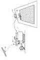
- the ordinary type combine 1(corresponding to “the harvester” according to the present invention) includes a crawler type traveling device 11, an operation unit 12, a threshing device 13, and a grain tank 14 (this It is provided with the "harvest storage tank” which concerns on invention, the harvesting apparatus H, the conveyance apparatus 16, the grain discharge apparatus 18, and the satellite positioning module 80.
- the traveling device 11is provided at the lower portion of the combine 1.
- the combine 1is configured to be self-propelled by the traveling device 11.
- the operating unit 12, the threshing device 13, and the grain tank 14are provided on the upper side of the traveling device 11.
- a supervisor who monitors the work of the combine 1can ride on the operation unit 12. The supervisor may monitor the operation of the combine 1 from the outside of the combine 1.
- the grain discharging device 18is provided on the upper side of the grain tank 14.
- the satellite positioning module 80is attached to the upper surface of the driver 12.
- the harvesting device His provided at the front of the combine 1.
- the transport device 16is provided on the rear side of the harvesting device H.
- the harvesting apparatus Hhas a reaper 15 and a reel 17.
- the reaper unit 15reaps the crop of the field in the field.
- the reel 17scrapes the cropped cereals to be harvested while being rotationally driven.
- the harvester Hharvests the field crop (corresponding to the "agricultural crop” according to the present invention). Then, the combine 1 can carry out a harvest run traveling by the traveling device 11 while harvesting the grain in the field by the harvesting device H.
- the combine 1is equipped with the harvesting device H which harvests the grain of a field, and the traveling device 11.
- the cropped rice bran that has been clipped by the cropping unit 15is transported by the transport device 16 to the threshing device 13.
- the reaping grainis threshed.
- the grain (corresponding to the “harvest” according to the present invention) obtained by the threshing processis stored in the grain tank 14.
- the grains stored in the grain tank 14are discharged to the outside by the grain discharging device 18 as needed.
- the combine 1includes a grain tank 14 for storing grains harvested by the harvesting device H.
- the communication terminal 4is disposed in the operation unit 12.
- the communication terminal 4is fixed to the operation unit 12.
- the present inventionis not limited to this, and the communication terminal 4 may be configured to be attachable to and detachable from the operation unit 12, and the communication terminal 4 may be located outside the machine of the combine 1 .
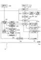
- the combine 1includes a control unit 20.
- the control unit 20includes a host vehicle position calculation unit 21, a travel route setting unit 22, and a travel control unit 23.
- the satellite positioning module 80receives GPS signals from the artificial satellite GS used in GPS (Global Positioning System). Then, as shown in FIG. 3, the satellite positioning module 80 sends positioning data to the vehicle position calculation unit 21 based on the received GPS signal.
- GPSGlobal Positioning System
- the vehicle position calculation unit 21calculates the position coordinates of the combine 1 based on the positioning data received from the satellite positioning module 80. The calculated position coordinates of the combine 1 are sent to the traveling control unit 23.
- the travel route setting unit 22sets a travel route in the field.
- the set travel routeis sent to the travel control unit 23.
- the traveling control unit 23controls the traveling of the combine 1 based on the position coordinates of the combine 1 received from the vehicle position calculation unit 21 and the traveling route received from the traveling route setting unit 22. More specifically, the traveling control unit 23 controls the combine 1 to travel along the traveling route set by the traveling route setting unit 22.
- combine 1 in this embodimentis constituted so that automatic travel is possible in a field.
- the procedure in the case of performing a field harvesting operation by this combine 1is as described below.
- the supervisormanually operates the combine 1 and, as shown in FIG. 2, harvests and travels along the border of the field at the outer peripheral portion in the field.
- the area which has become the existing areais set as the outer peripheral area SA.
- region left ungrounded inside inside peripheral area SAis set as work object area
- the supervisorcauses the combine 1 to travel 2-3 turns.
- the width of the outer peripheral area SAis increased by the work width of the combine 1 each time the combine 1 makes one revolution. That is, when traveling of two to three turns is completed, the width of the outer peripheral area SA becomes about two to three times the working width of the combine 1.
- the outer peripheral area SAis used as a space for the combine 1 to turn when the harvest traveling is performed in the work target area CA. Further, the outer peripheral area SA is also used as a space for movement, such as when moving to a discharge place of grain or after moving to a fuel supply place after the harvest traveling is once finished.
- the transport vehicle CV shown in FIG. 2can collect and transport the grains discharged from the grain discharging device 18 by the combine 1. At the time of grain discharging, the combine 1 moves to the vicinity of the carrier CV and then discharges the grain to the carrier CV by the grain discharging device 18.
- a travel route in the work target area CAis set.
- the travel routeis set by the travel route setting unit 22.
- the travel control unit 23controls the travel of the combine 1 so that the combine 1 automatically travels along the travel route. As shown in FIGS. 1 and 2, the automatic travel of the combine 1 is monitored by a supervisor.
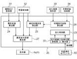
- the combine 1includes a deposition height detection unit 31, a weight detection unit 32, a travel distance detection unit 33, and a work state detection unit 34.
- the control unit 20further includes a limit weight calculation unit 24, a unit harvest weight calculation unit 25, a harvest traveling distance calculation unit 26, and a limit traveling distance calculation unit 27.
- the communication terminal 4also has a display unit 4a that displays various types of information.
- the deposition height detection unit 31includes a first sensor 31a, a second sensor 31b, a third sensor 31c, and a fourth sensor 31d.
- the first sensor 31 a, the second sensor 31 b, the third sensor 31 c, and the fourth sensor 31 dare all disposed inside the left side wall of the grain tank 14.
- the first sensor 31a, the second sensor 31b, the third sensor 31c, and the fourth sensor 31dare provided at the highest position, and the fourth sensor 31d is provided at the lowest position.
- the second sensor 31b and the third sensor 31care disposed between the first sensor 31a and the fourth sensor 31d in the height direction.
- the second sensor 31 bis provided at a position higher than the third sensor 31 c.
- the first sensor 31a, the second sensor 31b, the third sensor 31c, and the fourth sensor 31dare all pressure sensors, and output an ON signal when receiving pressure from the grain, and It is configured not to output the on signal when it is not received.
- the deposition height detection unit 31can detect the deposition height of the grains stored in the grain tank 14. For example, when grains in the grain tank 14 are deposited to a height between the third sensor 31c and the fourth sensor 31d, the fourth sensor 31d outputs an ON signal, and the first sensor 31a, the fourth sensor 31d, Both the second sensor 31 b and the third sensor 31 c do not output the on signal. Thereby, it is detected that the deposition height of the grain in the grain tank 14 is equal to or more than the height of the fourth sensor 31 d and less than the height of the third sensor 31 c.
- the combine 1includes the deposition height detection unit 31 that detects the deposition height of the kernels stored in the kernel tank 14.
- the deposition height detected by the deposition height detection unit 31is sent to the limit weight calculation unit 24.
- the weight detection unit 32is disposed in a state of being sandwiched between the grain tank 14 and the machine body frame 40.
- the weight detection unit 32temporally detects a grain weight which is a weight of the grain stored in the grain tank 14 based on the weight of the grain tank 14.
- the weight detection unit 32is configured by a load cell.
- the weight of the grain tank 14 and the grain weightare values indicating the weight of grain stored in the grain tank 14. Therefore, both the weight of the grain tank 14 and the grain weight correspond to the "stored weight" according to the present invention.
- the weight detection unit 32is configured to detect the grain weight as the “storage weight” according to the present invention.
- the present inventionis not limited to this, and the value detected by the weight detection unit 32 may be other than the grain weight as long as it indicates the weight of the grain stored in the grain tank 14 .
- the weight detection unit 32may be configured to detect the weight of the grain tank 14 as the "stored weight” according to the present invention.
- the combine 1includes the weight detection unit 32 that detects the grain weight, which is a value indicating the weight of the grain stored in the grain tank 14.
- the grain weight detected over time by the weight detection unit 32is sent to the limit weight calculation unit 24, the unit harvest weight calculation unit 25, and the limit travel distance calculation unit 27.
- the limit weight calculation unit 24calculates a limit weight which is a value indicating the weight of the grain of the storage limit amount of the grain tank 14. More specifically, the limit weight calculation unit 24 calculates the limit weight based on the grain weight received from the weight detection unit 32 and the deposition height of the grain received from the deposition height detection unit 31. . At this time, the limit weight calculation unit 24 calculates the limit weight by dividing the grain weight by the ratio of the detected deposition height to the upper limit value of the deposition height.
- the upper limit value of the deposition heightis the deposition height of grains in a state where grains of the storage limit amount are stored in the grain tank 14.
- the limit weight calculator 24determines that the 1000 kilogram is 0.5.
- the limit weightis calculated as 2000 kg by dividing by.
- the deposition height detection unit 31uses the on signal output from the first sensor 31a, the second sensor 31b, the third sensor 31c, and the fourth sensor 31d. Based on the detection of grain deposition height. Therefore, at the moment when the grain in the grain tank 14 reaches the height of any of the first sensor 31 a, the second sensor 31 b, the third sensor 31 c, and the fourth sensor 31 d, the detection result of the deposition height is , The most accurate.
- the limit weightis calculated based on the detected deposit height and the grain weight detected at that time. This makes it possible to calculate the limit weight with high accuracy.
- the limit weight calculated by the limit weight calculation unit 24is sent to the limit travel distance calculation unit 27.
- the combine 1includes the limit weight calculation unit 24 that calculates the limit weight which is a value indicating the weight of the grain of the storage limit amount of the grain tank 14.
- the limit weight calculation unit 24calculates the limit weight based on the grain weight detected by the weight detection unit 32 and the deposition height detected by the deposition height detection unit 31.
- the travel distance detection unit 33detects the travel distance of the combine 1 with time. Then, the travel distance detected by the travel distance detection unit 33 is sent to the harvest travel distance calculation unit 26.
- the working state detection unit 34detects over time whether the combine 1 is in a state of harvesting the grain of the field by the harvesting device H. Then, the detection result by the work state detection unit 34 is sent to the harvest travel distance calculation unit 26.
- the harvest traveling distance calculation unit 26temporally calculates the harvest traveling distance based on the traveling distance detected by the traveling distance detection unit 33 and the detection result by the working state detection unit 34.
- Harvesting distanceis the distance traveled during harvesting.
- the harvest travel distance calculation unit 26extracts the travel distance of the combine 1 by extracting only the travel distance in a state where the harvester H is harvesting the grain of the field from the travel distance of the combine 1. Calculate the distance.
- the harvest travel distance calculated with time by the harvest travel distance calculation unit 26is sent to the unit harvest weight calculation unit 25.
- the unit harvest weight calculation unit 25calculates a unit harvest weight based on the grain weight detected by the weight detection unit 32 and the harvest traveling distance calculated by the harvest traveling distance calculation unit 26.
- Unit harvest weightis the weight of grain to be harvested per unit harvest distance traveled.
- the unit harvest weight calculation unit 25calculates a unit harvest weight by dividing the increase in grain weight in a predetermined period by the harvest traveling distance in that period.
- the unit harvest weight calculated by the unit harvest weight calculation unit 25is sent to the limit travel distance calculation unit 27.
- the combine 1includes the unit harvest weight calculation unit 25 that calculates the unit harvest weight which is the weight of the grain to be harvested per unit harvest traveling distance.
- the limit travel distance calculation unit 27is configured to calculate the grain weight detected by the weight detection unit 32, the limit weight calculated by the limit weight calculation unit 24, and the unit harvest weight calculated by the unit harvest weight calculation unit 25. Based on the limit travel distance is calculated.
- the limit travel distanceis a limit distance that the combine 1 can travel by harvest traveling until the amount of grains stored in the grain tank 14 reaches the storage limit amount.
- the limit travel distance calculating unit 27calculates the limit travel distance by dividing the difference between the limit weight and the current grain weight by the unit harvest weight.
- the limit travel distance calculated by the limit travel distance calculation unit 27is sent to the communication terminal 4.
- the communication terminal 4displays the limit travel distance received from the limit travel distance calculation unit 27 on the display unit 4a.
- the combine 1includes the grain weight detected by the weight detection unit 32, the limit weight calculated by the limit weight calculation unit 24, and the unit harvest weight calculated by the unit harvest weight calculation unit 25. Based on this, a limit travel distance calculation unit 27 is provided which calculates a limit travel distance which is a limit distance which can be traveled by harvest traveling until the amount of grains stored in the grain tank 14 reaches the storage limit amount.
- the weight detection unit 32detects the grain weight which is a value indicating the weight of the grain stored in the grain tank 14.
- the limit weight calculation unit 24calculates a limit weight which is a value indicating the weight of the grain of the storage limit amount of the grain tank 14.
- the unit harvest weight calculation unit 25calculates a unit harvest weight which is the weight of the grain harvested per unit harvest traveling distance.
- a limit travel distancewhich is a limit distance, can be calculated.
- the limit weight calculation unit 24calculates the limit weight based on the grain weight received from the weight detection unit 32 and the deposition height of the grain received from the deposition height detection unit 31. .
- FIG. 6is a block diagram showing the configuration of the control unit 20 in the first modification of the first embodiment.
- the combine 1 in the first alternative embodimentincludes a moisture detection unit 35 and a map storage unit 28.
- the water detection unit 35is configured to detect the amount of water contained in the grain harvested by the harvester H. The water content detected by the water detection unit 35 is sent to the limit weight calculation unit 24.
- the combine 1includes the moisture detection unit 35 that detects the amount of moisture contained in the grain harvested by the harvesting device H.
- the map storage unit 28stores a map indicating a relationship between the weight of the storage limit amount of grain and the amount of water contained in the grain.
- the weight of the grain of the storage limit amountchanges with the water content contained in a grain. The relationship between the storage limit amount of grain weight and the amount of water contained in the grain can be experimentally examined.
- the limit weight calculation unit 24acquires, from the map storage unit 28, a map indicating the relationship between the weight of the grain of the storage limit amount and the amount of water contained in the grain. Then, the limit weight calculation unit 24 calculates the limit weight based on the map acquired from the map storage unit 28 and the amount of water detected by the water detection unit 35. The limit weight calculated by the limit weight calculation unit 24 is sent to the limit travel distance calculation unit 27.
- the limit weight calculation unit 24calculates the limit weight based on the amount of water detected by the water detection unit 35.
- the traveling device 11may be a wheel type or a semi crawler type.
- the graincorresponds to the "harvest” according to the present invention.
- the present inventionis not limited thereto, and the “harvest” may be other than grains.
- Examples of the “harvest” according to the present inventioninclude corn, potato, carrot, sugar cane and the like.
- the moisture detector 35may not be provided.
- the map storage unit 28may not be provided.
- the deposition height detection unit 31may not be provided.
- the host vehicle position calculation unit 21, the travel route setting unit 22, and the travel control unit 23may not be provided. That is, the "harvest machine" which concerns on this invention does not need to be what can be traveled automatically.
- the communication terminal 4 and the display unit 4amay not be provided.
- the supervisormanually operates the combine 1, and as shown in FIG. 2, the harvesting travels along the border of the field in the outer peripheral portion in the field.
- the present inventionis not limited to this, and the combine 1 may be configured to automatically travel and to perform harvest traveling so as to go around along the border of the field at the outer peripheral portion in the field.
- the travel route set by the travel route setting unit 22may be a straight route or a curved route.
- the present inventionmay be configured as a limit travel distance calculation program that causes a computer to realize the functions of the respective members in the above embodiment. Further, the present invention may be configured as a recording medium on which is recorded a limit travel distance calculation program that causes a computer to realize the function of each member in the above embodiment. Moreover, you may be comprised as a limit travel distance calculation method which performs what is performed by each member in the said embodiment by several steps.
- FIGS. 7 to 11a second embodiment of the present invention will be described with reference to FIGS. 7 to 11.
- the direction of arrow F shown in FIG. 7is “front”
- the direction of arrow Bis “rear”.
- the direction of the arrow U shown in FIG. 7is “up”
- the direction of the arrow Dis “down”.
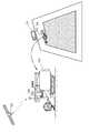
- the ordinary combine 101(corresponding to “agricultural work vehicle” according to the present invention) is a crawler type traveling device 111, an operation unit 112, a threshing device 113, a grain tank 114, a harvest
- the apparatus H, the transport apparatus 116, the grain discharging apparatus 118, and the satellite positioning module 180are provided.
- the combine 101also includes an engine 151 and a transmission 152.
- the traveling device 111is provided at the lower part of the combine 101. Further, the driving force of the engine 151 is shifted via the transmission 152 and transmitted to the traveling device 111. By this configuration, the combine 101 can travel by the traveling device 111 by itself.
- the operation unit 112, the threshing device 113, and the grain tank 114are provided on the upper side of the traveling device 111.
- a supervisor who monitors the work of the combine 101can ride on the operation unit 112. The supervisor may monitor the work of the combine 101 from the outside of the combine 101.
- the grain discharging device 118is provided on the upper side of the grain tank 114.
- the satellite positioning module 180is attached to the top surface of the driver 112.
- the harvesting device His provided at the front of the combine 101.
- the transport device 116is provided on the rear side of the harvesting device H.
- the harvesting apparatus Hhas a reaper 115 and a reel 117.
- the reaper 115harvests the crop of the field in the field.
- the reel 117scrapes the cropped cereals to be harvested while being rotationally driven.
- the harvester Hharvests the grain in the field.
- the combine 101can carry out a harvest run traveling by the traveling device 111 while harvesting the grain of the field by the harvesting device H.
- the cropped rice bran that has been clipped by the cropping unit 115is transported by the transport device 116 to the threshing device 113.
- the reaping grainis threshed.
- the grains obtained by the threshing processare stored in a grain tank 114.
- the grains stored in the grain tank 114are discharged to the outside by the grain discharging device 118 as needed.
- the communication terminal 104is disposed in the operation unit 112.
- the communication terminal 104is fixed to the operation unit 112.
- the present inventionis not limited to this, the communication terminal 104 may be configured to be attachable to and detachable from the operation unit 112, and the communication terminal 104 may be located outside the combine 101. .
- the combine 101includes a vehicle position calculation unit 121, a travel route setting unit 122, and a travel control unit 123.
- the satellite positioning module 180receives GPS signals from the artificial satellite GS used in GPS (Global Positioning System). Then, as shown in FIG. 9, the satellite positioning module 180 sends positioning data to the vehicle position calculation unit 121 based on the received GPS signal.
- GPSGlobal Positioning System
- the host vehicle position calculation unit 121calculates the position coordinates of the combine 101 based on the positioning data received from the satellite positioning module 180. The calculated position coordinates of the combine 101 are sent to the traveling control unit 123.
- the travel route setting unit 122sets a travel route in the field.
- the set travel routeis sent to the travel control unit 123.
- the traveling control unit 123controls the traveling of the combine 101 based on the position coordinates of the combine 101 received from the host vehicle position calculation unit 121 and the traveling route received from the traveling route setting unit 122. More specifically, the traveling control unit 123 controls the combine 101 to travel along the traveling route set by the traveling route setting unit 122.
- the combine 101 in this embodimentis comprised so that an automatic travel is possible in a field.
- the procedure in the case of performing the harvesting work in the field by this combine 101is as described below.
- the supervisormanually operates the combine 101, and as shown in FIG. 8, harvests and travels along the border line of the field in the outer peripheral part in the field.
- the area which has become the existing areais set as the outer peripheral area SA.
- region left ungrounded inside inside peripheral area SAis set as work object area
- the supervisortravels the combine 101 2 to 3 turns.
- the width of the outer peripheral area SAis expanded by the work width of the combine 101 every time the combine 101 makes one revolution. That is, when the traveling of 2 to 3 turns is completed, the width of the outer peripheral area SA becomes about 2 to 3 times the working width of the combine 101.
- the outer peripheral area SAis used as a space for the combine 101 to change its direction when performing harvest traveling in the work target area CA. Further, the outer peripheral area SA is also used as a space for movement, such as when moving to a discharge place of grain or after moving to a fuel supply place after the harvest traveling is once finished.
- the transport vehicle CV shown in FIG. 8can collect and transport the grains discharged from the grain discharging device 118 by the combine 101. At the time of grain discharging, the combine 101 moves to the vicinity of the carrier CV and then discharges the grain to the carrier CV by the grain discharging device 118.
- the travel route in the work target area CAis set.
- the travel routeis set by the travel route setting unit 122.
- the travel control unit 123controls the travel of the combine 101, whereby the combine 101 automatically travels along the travel route. As shown in FIGS. 7 and 8, the automatic travel of the combine 101 is monitored by a supervisor.
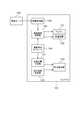
- the combine 101includes an information acquisition unit 153 and a turning speed control unit 154.
- the information acquisition unit 153is configured to be communicable with the management server 155 that manages the combine 101.
- field surface information on a field where the combine 101 performs a harvesting operationis stored.
- Field surface informationis information indicating the nature of the field surface.
- the field surface informationincludes information indicating the wet field tendency of each position in the field.
- the field surface informationincludes information indicating whether or not the field is a field.
- the field surface informationis generated based on the data input by the supervisor before the harvesting operation and is stored in the management server 155.
- the information acquisition unit 153acquires agricultural land surface information from the management server 155. Then, the acquired field surface information is sent to the turning speed control unit 154.
- the combine 101is provided with the information acquisition part 153 which acquires the field surface information which is the information which shows the property of the field surface.
- the satellite positioning module 180sends positioning data to the turning speed control unit 154 based on the received GPS signal. Then, the turning speed control unit 154 controls the engine 151 and the transmission 152 based on the field surface information received from the information acquisition unit 153 and the positioning data received from the satellite positioning module 180.
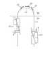
- FIG. 10is a diagram showing traveling of the combine 101 in a non-field field.
- traveling of the combine 101is indicated by an arrow.
- the combine 101performs two rounds of the first cornering T1 and the second cornering T2.
- a wet field location Wexists.
- the wet field location Whas a relatively large wet field tendency.
- the part other than the wet field location W in this fieldhas a relatively small wet field tendency.
- working T1is turning driving
- FIG. The second turning travel T2is a turning travel at the wet field site W.
- the turning speed control unit 154reduces the turning speed as compared to the case where the combine 101 makes a turn at a position where the wet field tendency is relatively small when the combine 101 makes a turn at a position where the wet field tendency is relatively large. , The engine 151 and the transmission 152 are controlled.
- the turning speed control unit 154compares the engine when the combine 101 turns at a position where the wet field tendency is relatively small. Decrease the rotational speed of 151.
- the turning speed control unit 154has a larger reduction ratio than when the combine 101 turns at a position where the wet field tendency is relatively small. As such, the transmission 152 is controlled.
- the rotational speed of the engine 151 in the second turning travel T2is lower than the rotational speed of the engine 151 in the first turning travel T1. Further, the reduction gear ratio of the transmission 152 in the second turning travel T2 is larger than the reduction ratio of the transmission 152 in the first turning travel T1.
- the turning speed in the second turning travel T2is lower than the turning speed in the first turning travel T1.
- a dotted lineindicates that the turning speed in the second turning travel T2 is relatively low.
- the turning speed control unit 154reduces the turning speed when turning at a position where the wet field tendency is relatively large as compared to when turning at a position where the wet field tendency is relatively small.
- FIG. 11is a diagram showing the traveling of the combine 101 in the field.
- traveling of the combine 101is indicated by an arrow.
- the combine 101performs two turning travels of the third turning travel T3 and the fourth turning travel T4.
- the turning speed control unit 154controls the engine 151 and the transmission 152 so that the turning speed is reduced when the combine 101 travels in a field compared to when the combine 101 travels in a field other than a field.
- the turning speed control unit 154reduces the rotational speed of the engine 151 when the combine 101 travels in a field compared to when the combine 101 travels in a field other than a field.
- the turning speed control unit 154controls the transmission 152 so that the reduction gear ratio is larger than when the combine 101 travels in a field other than a field.
- the rotational speed of the engine 151 in the third turning travel T3 and the fourth turning travel T4is higher than the rotation speed of the engine 151 in the first turning travel T1 shown in FIG. Low.
- the reduction gear ratio of the transmission 152 in the third turning travel T3 and the fourth turning travel T4is larger than the reduction ratio of the transmission 152 in the first turning travel T1 shown in FIG.
- the turning speed in the third turning travel T3 and the fourth turning travel T4is lower than the turning speed in the first turning travel T1.
- the turning speed control unit 154when traveling in a field, the turning speed control unit 154 reduces the turning speed as compared to traveling in a field that is not a field. Moreover, the combine 101 is equipped with the turning speed control part 154 which controls turning speed based on the field surface information acquired by the information acquisition part 153. FIG.
- the traveling device 111may be a wheel type or a semi crawler type.
- the field surface informationis generated based on the data input by the supervisor before the harvesting operation and is stored in the management server 155.
- the present inventionis not limited to this.
- the field surface informationmay be generated based on data such as slips detected by various sensors included in the farm vehicle and inclination of a vehicle body in an agricultural work performed in the past in the field.
- the information acquisition unit 153is configured to acquire the agricultural land surface information from the management server 155.
- the present inventionis not limited to this, and the information acquisition unit 153 may be configured to acquire the field surface information generated by the combine 101.
- the combine 101is equipped with a camera, and at the start of a harvesting operation in the field, the field is photographed by the camera, image processing using artificial intelligence is performed to generate field surface information, and this field surface information is acquired by the information acquisition unit 153 May be configured to obtain.
- the soil moisture sensordetects the soil moisture amount on the field surface, and based on the detected soil moisture amount
- the informationmay be configured to generate information indicating the tendency of the wet field at each position in the field.
- the combine 101is equipped with a thermo camera and estimates the soil water content of the field surface using the thermo camera, and based on the estimated soil water content, generates information indicating the wet field tendency of each position in the field It may be configured as follows.
- the turning speed control unit 154may be configured to control only one of the engine 151 and the transmission 152. Further, the turning speed control unit 154 may be configured to control elements other than the engine 151 and the transmission 152 in order to control the turning speed.
- the field surface informationmay not include information indicating whether or not the field is a field.
- the field surface informationmay not include the information indicating the wet field tendency of each position in the field.
- the host vehicle position calculation unit 121, the travel route setting unit 122, and the travel control unit 123may not be provided. That is, the "growing vehicle" according to the present invention may not be capable of traveling automatically.
- the supervisormanually operates the combine 101, and as shown in FIG. 8, in the outer peripheral portion in the field, the harvest travels so as to go around along the border of the field.
- the present inventionis not limited to this, and the combine 101 may be configured to automatically travel and to perform harvest traveling so as to orbit along the border of the field at the outer peripheral portion in the field.
- the travel route set by the travel route setting unit 122may be a straight route or a curved route.
- the present inventionmay be configured as a turning control program that causes a computer to realize the function of each member in the above embodiment.
- the present inventionmay be configured as a recording medium on which a swing control program that causes a computer to realize the function of each member in the above embodiment is recorded.
- youmay be comprised as a turning control method which performs what is performed by each member in the said embodiment by several steps.
- FIGS. 12 to 23a third embodiment of the present invention will be described with reference to FIGS. 12 to 23.
- the direction of arrow F shown in FIG. 12is “front”
- the direction of arrow Bis “rear”.
- the direction of the arrow U shown in FIG. 12is “up”
- the direction of the arrow Dis “down”.
- the ordinary combine 201includes a crawler-type traveling device 211, a driving unit 212, a threshing device 213, a grain tank 214, a harvesting device H, a conveying device 216, a grain discharging device 218, satellite positioning.
- a module 280is provided.
- the traveling device 211is provided at the lower part of the combine 201.
- the combine 201can be self-propelled by the traveling device 211.
- the driving unit 212, the threshing device 213, and the grain tank 214are provided on the upper side of the traveling device 211.
- An operator who monitors the operation of the combine 201can get on the operation unit 212.
- the workermay monitor the work of the combine 201 from the outside of the combine 201.
- the grain discharging device 218is provided on the upper side of the grain tank 214.
- the satellite positioning module 280is attached to the top surface of the driver 212.
- the harvesting device His provided at the front of the combine 201.
- the transport device 216is provided on the rear side of the harvesting device H.
- the harvesting device Halso has a reaper 215 and a reel 217.
- the reaper 215reaps the field crop of the field.
- the reel 217scrapes the cropping object of harvest while being rotationally driven.
- the harvester Hharvests the grain in the field.
- combine 201can reap travel which runs by traveling device 211, while reaping a crop of a field of a field with reaper 215.
- the cropped rice straw which has been cut by the reaper 215is transported by the transport device 216 to the threshing device 213.
- the reaping grainis threshed.
- the grains obtained by the threshing processare stored in a grain tank 214.
- the grains stored in the grain tank 214are discharged to the outside by the grain discharging device 218 as needed.
- the combine 201has a grain tank 214 for storing grains.
- the communication terminal 204is disposed in the operation unit 212.
- the communication terminal 204is configured to be able to display various information.
- the communication terminal 204is fixed to the driver 212.
- the present inventionis not limited to this.
- the communication terminal 204may be configured to be attachable to and detachable from the operation unit 212, and the communication terminal 204 may be located outside the combine 201. .
- the combine 201performs circulation while harvesting grains in the area on the outer periphery side of the field as shown in FIG. 14, then the combine 201 performs the cutting and traveling in the inner area of the field as shown in FIG. 16. , Are configured to harvest the grain of the field.
- the combine 201is controlled by the combine control system A.
- the configuration of the combine control system Awill be described below.
- the combine control system Aincludes a satellite positioning module 280, a control unit 220, and a weight sensor 214S.
- the control unit 220 and the weight sensor 214Sare provided in the combine 201.
- the satellite positioning module 280is also provided in the combine 201.
- the control unit 220includes a vehicle position calculation unit 221, a route calculation unit 222, a travel control unit 223, an area calculation unit 224, a detection unit 225, an acquisition unit 226, a determination unit 227, a discharge control unit 228, an upper limit setting unit 229, An upper limit reducing unit 230, a retry monitoring unit 231, an actual turning radius calculation unit 232, and a target turning radius calculation unit 233 are provided.
- the satellite positioning module 280receives GPS signals from the artificial satellite GS used in GPS (Global Positioning System). Then, as shown in FIG. 13, the satellite positioning module 280 sends positioning data indicating the vehicle position of the combine 201 to the vehicle position calculation unit 221 based on the received GPS signal.
- GPSGlobal Positioning System
- the host vehicle position calculation unit 221calculates position coordinates of the combine 201 with time based on the positioning data output by the satellite positioning module 280.
- the calculated positional coordinates of the combine 201 over timeare sent to the traveling control unit 223, the area calculation unit 224, the actual turning radius calculation unit 232, and the target turning radius calculation unit 233.
- the area calculation unit 224calculates the outer peripheral area SA and the work target area CA based on the temporal position coordinates of the combine 201 received from the host vehicle position calculation unit 221.
- the area calculation unit 224calculates the traveling locus of the combine 201 in the circumferential traveling on the outer periphery side of the field based on the temporal position coordinate of the combine 201 received from the vehicle position calculation unit 221. .
- region calculation part 224calculates the area
- region SAbased on the calculated traveling locus of the combine 201.
- the area calculation unit 224calculates the inside of the calculated outer peripheral area SA as the work target area CA.
- the traveling route of the combine 201 for the circumferential traveling on the outer circumference side of the farmlandis indicated by an arrow.
- the combine 201performs three rounds.
- the fieldis in the state shown in FIG.
- the area calculation unit 224calculates an area on the outer circumference side of the field where the combine 201 travels while harvesting the grain as the outer circumference area SA. In addition, the area calculation unit 224 calculates the inside of the calculated outer peripheral area SA as the work target area CA.
- the calculation result by the area calculation unit 224is sent to the route calculation unit 222.
- the route calculation unit 222includes a cutting traveling route calculation unit 222 a and a turning route calculation unit 222 b.
- the reaper traveling route calculation unit 222acalculates a reaper traveling route LI, which is a traveling route for reaper traveling in the work target area CA, based on the calculation result received from the area calculation unit 224.
- the cutting traveling path LIis a plurality of parallel lines parallel to one another.
- the reaper traveling route LI calculated by the reaper traveling route calculating unit 222 ais sent to the traveling control unit 223.
- the traveling control unit 223controls automatic traveling of the combine 201 based on the position coordinates of the combine 201 received from the host vehicle position calculation unit 221 and the reaper traveling route LI received from the reaper traveling route calculation unit 222a. More specifically, as shown in FIG. 16, the traveling control unit 223 controls the traveling of the combine 201 so that the reaper traveling is performed by the automatic traveling along the reaper traveling route LI.
- the turning route calculation unit 222 bis configured to receive the position coordinates of the combine 201 from the host vehicle position calculation unit 221. Then, based on the position coordinates of the combine 201 received from the host vehicle position calculation unit 221 and the calculation result received from the area calculation unit 224, the turning route calculation unit 222b, as shown in FIG.
- the U-turn path LU(corresponding to the “turning path” according to the present invention) in is calculated.
- the U-turn path LUis calculated in a U-shape so as to connect the end portions of the two cutting travel paths LI. Further, the turning route calculation unit 222b calculates the U-turn route LU so as to connect the reaper traveling route LI currently being traveled by the combine 201 and the reaper traveling route LI scheduled for next by the combine 201 to travel next. .
- the U-turn path LUis semicircular.
- the present inventionis not limited to this.
- the U-turn path LUmay be U-shaped including a straight portion.
- the U-turn path LUis not limited to a traveling path connecting two adjacent cutting paths LI, but is a traveling path connecting two cutting paths LI sandwiching one or more cutting paths LI. It is good.
- the U-turn route LU calculated by the turning route calculation unit 222 bis sent to the traveling control unit 223.
- the traveling control unit 223controls the automatic traveling of the combine 201 based on the position coordinates of the combine 201 received from the host vehicle position calculation unit 221 and the U-turn route LU received from the turning route calculation unit 222 b. More specifically, the traveling control unit 223 controls the traveling of the combine 201 so that turning is performed by automatic traveling along the U-turn path LU.
- the weight sensor 214Salso detects the storage weight of the grain in the grain tank 214.
- the detection result of the weight sensor 214Sis sent to the detection unit 225, the determination unit 227, and the upper limit value reduction unit 230.
- the upper limit setting unit 229sets the upper limit of the storage weight of grains in the grain tank 214.
- the upper limit value set by the upper limit value setting unit 229is sent to the detection unit 225.
- the detection unit 225determines whether the storage weight of the grain in the grain tank 214 has reached the upper limit value based on the detection result received from the weight sensor 214S and the upper limit value received from the upper limit value setting unit 229. Monitor Then, when the stored weight of grain in the grain tank 214 reaches the upper limit value, the detection unit 225 detects that the stored weight of grain in the grain tank 214 reaches the upper limit value.
- the combine control system Ais provided with the detection part 225 which detects that the storage weight of the grain in the grain tank 214 reached the upper limit.
- the detection result by the detection unit 225is sent to the discharge control unit 228.
- the discharge control unit 228causes the combine 201 to start the grain discharge operation.
- the grain discharging operationis an operation for discharging grains from the grain tank 214.
- the operatormanually operates the combine 201, and as shown in FIG. 14, in the outer peripheral portion in the field, the mowing travel is performed so as to go around along the border of the field.
- the combine 201performs three rounds. When this round trip is completed, the field is in the state shown in FIG.
- the area calculation unit 224calculates the traveling locus of the combine 201 in the round trip shown in FIG. 14 based on the temporal position coordinates of the combine 201 received from the host vehicle position calculation unit 221. Then, as shown in FIG. 15, the area calculation unit 224 uses the area on the outer circumference side of the field where the combine 201 travels while harvesting the set up of rice husks based on the calculated travel locus of the combine 201. Calculated as In addition, the area calculation unit 224 calculates the inside of the calculated outer peripheral area SA as the work target area CA.
- the reaper traveling path calculation unit 222asets a reaper traveling route LI in the work target area CA.
- the turning route calculation unit 222bcalculates a U-turn route LU in the outer peripheral area SA, as shown in FIG.
- the turning route calculation unit 222bcalculates the U-turn route LU so as to connect the reaper traveling route LI currently being traveled by the combine 201 and the reaper traveling route LI scheduled for next by the combine 201 to travel next.
- the traveling control unit 223controls the traveling of the combine 201 so that turning is performed by automatic traveling along the U-turn route LU.
- the combine 201can move from the end of the currently traveling reaper traveling path LI to the end of the reaper traveling path LI to be traveled next.
- the turning route calculation unit 222 bcauses the combine 201 to travel again.
- the U-turn path LUis calculated so as to connect the reaping travel path LI being taken and the reaping travel path LI where the combine 201 is to travel next.
- the turning path calculation unit 222bdetermines that the traveling order is the first.
- a U-turn path LU connecting a certain reaping travel path LI and the reaping travel path LI where the traveling order is secondis calculated.
- the turning path calculation unit 222bdetermines that the traveling order is the second.
- a U-turn path LU connecting a certain reaping travel path LI and the reaping travel path LI where the traveling order is the thirdis calculated.
- the transport vehicle CVis parked outside the field. Then, in the outer peripheral area SA, the stop position PP is set at a position near the transport vehicle CV.
- the transporter CVcan collect and transport the grains discharged by the combine 201 from the grain discharge device 218.
- the combine 201stops at the stopping position PP and discharges the grain to the transport vehicle CV by the grain discharging device 218.
- the detection unit 225detects that the storage weight of the grain in the grain tank 214 reaches the upper limit value. .
- the discharge control unit 228causes the combine 201 to start the grain discharge operation as shown in FIG.
- the detection unit 225detects that the storage weight of the grain in the grain tank 214 has reached the upper limit value at the position P1 on the cutting traveling path LI shown in FIG. . Thereby, as shown in FIG. 17, the combine 201 starts the grain discharging operation at the position P1 on the reaper traveling route LI.
- the combine 201leaves the reaping travel route LI at a position P1 on the reaping travel route LI. Subsequently, in order to move to the stopping position PP, the combine 201 travels in the outer peripheral area SA. Then, the combine 201 stops at the stopping position PP, and discharges the grains to the transport vehicle CV by the grain discharging device 218.
- the combine 201After discharging the grain, as shown in FIG. 18, the combine 201 returns to the automatic traveling along the cutting traveling path LI. Then, when the mowing travel along all the mowing travel paths LI in the work target area CA is completed, the entire field becomes harvested.
- the traveling control unit 223sends a signal indicating the execution of the retry to the retry monitoring unit 231, as shown in FIG.
- This signalcontains information indicating the position where the retry is to be performed in the field.
- the retry monitoring unit 231includes a first retry number counting unit 231a, a second retry number counting unit 231b, and a retry turning number counting unit 231c.
- the first retry count counting unit 231 acounts the first retry count based on the signal received from the traveling control unit 223.
- the first retry numberis the number of retries by the combine 201 in one U-turn path LU.
- the acquisition unit 226is configured to acquire the first retry number from the first retry number counting unit 231a.
- the acquired first retry countis sent from the acquisition unit 226 to the determination unit 227.
- the acquisition unit 226is configured to acquire the first retry number, which is the number of retries by the combine 201 in one U-turn path LU.
- the determination unit 227determines whether the turning accuracy of the combine 201 has decreased based on the detection result received from the weight sensor 214S and the first retry count received from the acquisition unit 226.
- the determination unit 227determines the turning accuracy of the combine 201 when the number of first retries reaches a predetermined first number in a state where the storage weight of grains in the grain tank 214 is a predetermined weight or more. Is determined to have dropped.
- the predetermined weightmay be, for example, the weight of the grain corresponding to 50% of the storage space in the grain tank 214, or may be the weight other than that.
- the first numberis set to four.
- the present inventionis not limited to this, and the first number may be a number other than four.
- the turning accuracyis a degree of smallness of deviation of an actual turning locus with respect to a planned turning path.
- the turning accuracy in the present embodimentmeans the degree of smallness of the deviation of the actual turning trajectory of the combine 201 with respect to the U-turn path LU.
- the determination result by the determination unit 227is sent to the discharge control unit 228 and the upper limit value reduction unit 230.
- the upper limit value reducing unit 230determines that the upper limit of the storage weight of grains is determined by the determining unit 227 and the turning accuracy of the combine 201 is decreased.
- An upper limit value setting unit 229sends an instruction signal to change to the stored weight of grain at the time point.
- the upper limit setting unit 229resets the upper limit of the storage weight of the grain according to the instruction signal. As a result, the upper limit of the storage weight of grains is reduced.
- the combine control system Aincludes the upper limit value reduction unit 230 that reduces the upper limit value when the determination unit 227 determines that the turning accuracy of the combine 201 is lowered. If the determination unit 227 determines that the turning accuracy of the combine 201 has decreased, the upper limit reducing unit 230 determines that the upper limit is determined by the determining unit 227 that the turning accuracy of the combine 201 has decreased. The stored weight of grain in grain tank 214 is changed.
- the discharge control unit 228causes the combine 201 to start the grain discharging operation.
- the combine control system Aincludes the discharge control unit 228 that starts the grain discharge operation when the determination unit 227 determines that the turning accuracy of the combine 201 is lowered.
- the combine 201performs the turning operation along one U-turn path LU.
- the storage weight of the grain in the grain tank 214is a predetermined weight or more.
- a retryis performed at the position Q1, the position Q2, and the position Q3.
- the combine 201returns on the U-turn path LU by the retry performed at the position Q3.
- the first number of retriesis three.
- the first numberis set to four. Therefore, the first retry count has not reached the first count. Therefore, the determination unit 227 determines that the turning accuracy of the combine 201 has not decreased.
- the combine 201performs the turning operation along one U-turn path LU.
- the storage weight of the grain in the grain tank 214is a predetermined weight or more.
- a retryis performed at the position Q4, the position Q5, the position Q6, and the position Q7.
- the determination unit 227determines that the turning accuracy of the combine 201 has decreased.
- the upper limit reducing unit 230is configured to change the upper limit value of the storage weight of grain to the current storage weight of grain, the upper limit signal It sends to the value setting unit 229.
- the upper limit setting unit 229resets the upper limit of the storage weight of the grain according to the instruction signal. As a result, the upper limit of the storage weight of grains is reduced.
- the discharge control unit 228causes the combine 201 to start the grain discharge operation. Thereby, the combine 201 stops the turning operation immediately after the fourth retry and moves to the stop position PP. Then, the combine 201 stops at the stopping position PP, and discharges the grains to the transport vehicle CV by the grain discharging device 218.
- the second retry number counting unit 231b illustrated in FIG. 13counts the second retry number based on the signal received from the traveling control unit 223.
- the second retry numberis the cumulative number of retries in the turning operation by the combine 201.
- the acquiring unit 226is configured to acquire the second retry number from the second retry number counting unit 231b.
- the acquired second retry countis sent from the acquisition unit 226 to the determination unit 227.
- the acquisition unit 226is configured to acquire the second retry number, which is the cumulative number of retries in the turning operation by the combine 201.
- the determination unit 227determines whether the turning accuracy of the combine 201 has decreased based on the detection result received from the weight sensor 214S and the second retry count received from the acquisition unit 226.
- the determination unit 227determines the turning accuracy of the combine 201 when the second retry count reaches a predetermined second count in a state where the storage weight of the kernel in the kernel tank 214 is a predetermined weight or more. Is determined to have dropped.
- the second numberis set to six.
- the present inventionis not limited to this, and the second number may be a number other than six.
- the retry turning number counting unit 231 ccounts the retry turning number based on the signal received from the traveling control unit 223. Note that the number of times of retry turning is the number of turning operations in which a retry is performed among the turning operations by the combine 201.
- the acquisition unit 226is configured to acquire the number of times of retry turning from the retry turning number counting unit 231 c.
- the acquired retrying number of timesis sent from the acquisition unit 226 to the determination unit 227.
- the acquiring unit 226is configured to acquire the number of times of retry turning that is the number of times of the turning operation in which the retry has been performed among the turning operations by the combine 201.
- the determination unit 227determines whether or not the turning accuracy of the combine 201 has decreased based on the detection result received from the weight sensor 214S and the number of times of retry turning received from the obtaining unit 226.
- the determination unit 227determines that the turning accuracy of the combine 201 is high when the number of times of retry turning reaches a predetermined third number. It determines that it has fallen.
- the third numberis set to four.
- the present inventionis not limited to this, and the third number may be other than four.
- the combine 201performs a harvesting operation in the field.
- the already-cropped area CA2is an area in which the reaping work has already been completed. Then, the combine 201 reaps the built-in grain weirs of the uncut area CA1 in the work target area CA.
- the combine 201When the combine 201 is located at the position P2 shown in FIG. 21, it is assumed that the storage weight of the grain in the grain tank 214 of the combine 201 is equal to or more than a predetermined weight. Then, under the control of the travel control unit 223, the combine 201 performs the reaping travel along the reaping travel path LI from the position P2.
- three U-turn paths LU of a first U-turn path LU1, a second U-turn path LU2, and a third U-turn path LU3are calculated along with the reaping travel along the reaping travel path LI.
- the combine 201travels from the position P2 along the reaping travel path LI and performs a turning operation on the first U-turn path LU1.
- the combine 201has never retried in the turning operation in this field until the turning operation is performed in the first U-turn path LU1.
- the first numberis set to four. That is, in the first U-turn path LU1, the first retry count has not reached the first count.
- the second retry number counted by the second retry number counting unit 231bis three times by the turning operation on the first U-turn path LU1.
- the second numberis set to six. That is, in the turning operation on the first U-turn path LU1, the second retry number has not reached the second number.
- the number of retry turns counted by the retry turn number counting unit 231cis one by the turning operation on the first U-turn path LU1.
- the third numberis set to four. That is, in the turning operation on the first U-turn path LU1, the number of times of retry turning has not reached the third number.
- the determination unit 227determines that the turning accuracy of the combine 201 has not decreased.
- combine 201performs mowing travel along mowing travel path LI, and performs turning operation in the second U-turn path LU2.
- one retryis performed in the turning operation on the second U-turn path LU2.
- the first retry counthas not reached the first count.
- the second retry number counted by the second retry number counting unit 231bis four times by the turning operation on the second U-turn path LU2. That is, in the turning operation on the second U-turn path LU2, the second retry number has not reached the second number.
- the number of retry turns counted by the retry turn number counting unit 231cis two due to the turning operation on the second U-turn route LU2. That is, in the turning operation on the second U-turn path LU2, the number of retry turns has not reached the third number.
- the determination unit 227determines that the turning accuracy of the combine 201 is not lowered.
- combine 201performs mowing travel along mowing travel path LI, and performs turning operation in the third U-turn path LU3.
- two retriesare performed in the turning operation on the third U-turn path LU3.
- the number of retry turns counted by the retry turn number counting unit 231cis three times by the turning operation on the third U-turn path LU3. That is, in the turning operation on the third U-turn path LU3, the number of times of retry turning has not reached the third number.
- the second retry number counted by the second retry number counting unit 231breaches six.
- the determination unit 227determines that the turning accuracy of the combine 201 has decreased.
- the upper limit reducing unit 230is configured to change the upper limit value of the storage weight of grain to the current storage weight of grain, the upper limit signal It sends to the value setting unit 229.
- the upper limit setting unit 229resets the upper limit of the storage weight of the grain according to the instruction signal. As a result, the upper limit of the storage weight of grains is reduced.
- the discharge control unit 228causes the combine 201 to start the grain discharge operation.
- the combine 201cancels the turning operation immediately after the second retry in the turning operation on the third U-turn route LU3, and moves to the stopping position PP.
- the combine 201stops at the stopping position PP, and discharges the grains to the transport vehicle CV by the grain discharging device 218.
- the combine 201is performing the harvesting work in the field.
- the already-cropped area CA2is an area in which the reaping work has already been completed. Then, the combine 201 reaps the built-in grain weirs of the uncut area CA1 in the work target area CA.
- the combine 201When the combine 201 is located at the position P3 shown in FIG. 22, it is assumed that the storage weight of the grain in the grain tank 214 of the combine 201 is equal to or more than a predetermined weight. Then, under the control of the travel control unit 223, the combine 201 performs the reaping travel along the reaping travel path LI from the position P3.
- the combine 201travels from the position P3 along the reaping travel path LI and performs a turning operation on the fourth U-turn path LU4.
- the combine 201has never retried the turning operation in this field until the turning operation is performed in the fourth U-turn path LU4.
- one retryis performed in the turning operation on the fourth U-turn path LU4.
- the first numberis set to four. That is, in the fourth U-turn path LU4, the first number of retries has not reached the first number.
- the second retry number counted by the second retry number counting unit 231bis one due to the turning operation on the fourth U-turn path LU4.
- the second numberis set to six. That is, in the turning operation on the fourth U-turn path LU4, the second retry number has not reached the second number.
- the number of retry turns counted by the retry turn number counting unit 231cis one by the turning operation on the fourth U-turn path LU4.
- the third numberis set to four. That is, in the turning operation on the fourth U-turn path LU4, the number of retry turns has not reached the third number.
- the determination unit 227determines that the turning accuracy of the combine 201 is not lowered.
- combine 201performs mowing travel along mowing travel path LI, and performs turning operation in the 5th U-turn path LU5.
- one retryis performed in the turning operation on the fifth U-turn path LU5.
- the second retry number counted by the second retry number counting unit 231bis twice due to the turning operation on the fifth U-turn path LU5. That is, in the turning operation on the fifth U-turn path LU5, the second retry number has not reached the second number.
- the number of retry turns counted by the retry turn number counting unit 231cis two due to the turning operation on the fifth U-turn path LU5. That is, in the turning operation on the fifth U-turn path LU5, the number of retry turns has not reached the third number.
- the determination unit 227determines that the turning accuracy of the combine 201 is not lowered.
- combine 201performs mowing travel along mowing travel path LI, and performs turning operation in the sixth U-turn path LU6.
- no retryis performed in the turning operation on the sixth U-turn path LU6.
- the second retry number counted by the second retry number counting portion 231bis not increased by the turning operation on the sixth U-turn path LU6 and remains twice. That is, in the turning operation on the sixth U-turn path LU6, the second retry number has not reached the second number.
- the number of retry turns counted by the retry turn number counting unit 231cis not increased by the turning operation on the sixth U-turn path LU6, and remains twice. That is, in the turning operation on the sixth U-turn path LU6, the number of retry turns has not reached the third number.
- the determination unit 227determines that the turning accuracy of the combine 201 is not lowered.
- combine 201performs mowing travel along mowing travel path LI, and performs turning operation in the 7th U-turn path LU7.
- two retriesare performed in the turning operation on the seventh U-turn path LU7.
- the second retry number counted by the second retry number counting unit 231bis four times by the turning operation on the seventh U-turn path LU7. That is, in the turning operation on the seventh U-turn path LU7, the second retry number has not reached the second number.
- the number of retry turns counted by the retry turn number counting unit 231cis three times by the turning operation on the seventh U-turn route LU7. That is, in the turning operation on the seventh U-turn path LU7, the number of retry turns has not reached the third number.
- the determination unit 227determines that the turning accuracy of the combine 201 is not lowered.
- combine 201performs mowing travel along mowing travel path LI, and performs turning operation in the eighth U-turn path LU8.
- one retryis performed in the turning operation on the eighth U-turn path LU8.
- the first number of retrieshas not reached the first number.
- the second retry count counted by the second retry count counting unit 231bis five. That is, at this time, the second retry count has not reached the second count.
- the number of retry turns counted by the retry turn number counting unit 231creaches four.
- the determination unit 227determines that the turning accuracy of the combine 201 has decreased.
- the upper limit reducing unit 230is configured to change the upper limit value of the storage weight of grain to the current storage weight of grain, the upper limit signal It sends to the value setting unit 229.
- the upper limit setting unit 229resets the upper limit of the storage weight of the grain according to the instruction signal. As a result, the upper limit of the storage weight of grains is reduced.
- the discharge control unit 228causes the combine 201 to start the grain discharge operation.
- the combine 201stops the turning operation immediately after the retry and moves to the stopping position PP.
- the combine 201stops at the stopping position PP, and discharges the grains to the transport vehicle CV by the grain discharging device 218.
- control unit 220 illustrated in FIG. 13includes the actual turning radius calculation unit 232 and the target turning radius calculation unit 233.
- the target turning radius calculation unit 233acquires the reaper traveling route LI calculated by the reaper traveling route calculating unit 222 a. Further, the target turning radius calculation unit 233 acquires the U-turn route LU calculated by the turning route calculation unit 222 b.
- the target turning radius calculation unit 233causes the combine 201 to travel next based on the acquired cutting travel route LI and U-turn route LU and the position coordinates of the combine 201 received from the vehicle position calculation unit 221.
- the turning radius of the scheduled U-turn path LUis calculated.
- the turning radius calculated by the target turning radius calculation unit 233is the target turning radius TR when the combine 201 turns next along the U-turn path LU. That is, the target turning radius calculation unit 233 calculates the target turning radius TR when the combine 201 turns next along the U-turn path LU.
- the actual turning radius calculation unit 232calculates the actual turning radius AR of the combine 201 based on the temporal position coordinates of the combine 201 received from the host vehicle position calculation unit 221.
- the acquisition unit 226is configured to acquire the calculated target turning radius TR from the target turning radius calculation unit 233.
- the acquisition unit 226is configured to acquire the calculated actual turning radius AR from the actual turning radius calculation unit 232.
- the acquisition unit 226is configured to acquire the target turning radius TR of the combine 201 and the actual turning radius AR of the combine 201.
- the acquired target turning radius TR and the actual turning radius ARare sent from the acquisition unit 226 to the determination unit 227.
- the determination unit 227calculates the difference between the target turning radius TR and the actual turning radius AR.
- the determination unit 227determines whether or not the turning accuracy of the combine 201 has decreased based on the detection result received from the weight sensor 214S and the difference between the target turning radius TR and the actual turning radius AR.
- the determination unit 227determines that the difference between the target turning radius TR and the actual turning radius AR is equal to or more than the predetermined value. It is determined that the turning accuracy of the combine 201 has decreased.
- the predetermined valuecan be appropriately set in accordance with the model of the combine 201 or the like.
- the combine 201performs the turning operation along one U-turn path LU.
- the storage weight of the grain in the grain tank 214is a predetermined weight or more.
- the target turning radius TRis calculated by the target turning radius calculation unit 233 before the turning operation along the U-turn path LU is performed. Then, when the turning operation along the U-turn path LU is started, the actual turning radius calculation unit 232 calculates the actual turning radius AR.
- the determination unit 227determines that the turning accuracy of the combine 201 is lowered.
- the upper limit reducing unit 230is configured to change the upper limit value of the storage weight of grain to the current storage weight of grain, the upper limit signal It sends to the value setting unit 229.
- the upper limit setting unit 229resets the upper limit of the storage weight of the grain according to the instruction signal. As a result, the upper limit of the storage weight of grains is reduced.
- the discharge control unit 228causes the combine 201 to start the grain discharge operation. Thereby, the combine 201 cancels the turning operation without retrying, and moves to the stopping position PP. Then, the combine 201 stops at the stopping position PP, and discharges the grains to the transport vehicle CV by the grain discharging device 218.
- the combine 201will retry.
- the first retry number, the second retry number, and the retry turning number described aboveare all information indicating the turning accuracy of the combine 201. Therefore, each of the first retry number, the second retry number, and the retry turning number corresponds to the "turning accuracy information" according to the present invention.
- the difference between the target turning radius TR and the actual turning radius ARis also information indicating the turning accuracy of the combine 201. Therefore, the difference between the target turning radius TR and the actual turning radius AR also corresponds to the "turning accuracy information" according to the present invention.
- the acquisition unit 226is configured to acquire turning accuracy information.
- the determination unit 227determines whether or not the turning accuracy of the combine 201 has decreased based on the turning accuracy information acquired by the acquiring unit 226.
- the combine control system Aincludes the acquisition unit 226 that acquires turning accuracy information that is information indicating the turning accuracy of the combine 201. Further, the combine control system A includes a determination unit 227 that determines whether or not the turning accuracy of the combine 201 has decreased based on the turning accuracy information acquired by the acquiring unit 226.
- the upper limit reducing unit 230decreases the upper limit of the storage weight of grains in the grain tank 214.
- the storage weight of grains in the grain tank 214is unlikely to increase to such an extent that the turning accuracy decreases. That is, after the upper limit value of the storage weight of the grain in the grain tank 214 decreases, it is easy to ensure the turning accuracy of the combine 201.
- the traveling device 211may be a wheel type or a semi crawler type.
- the reaper traveling route LI calculated by the reaper traveling route calculating unit 222ais a plurality of parallel lines parallel to each other, but the present invention is not limited to this, and the reaper traveling route calculating unit
- the crop traveling path LI calculated by 222amay not be a plurality of parallel lines parallel to each other.
- the reaper traveling route LI calculated by the reaper traveling route calculating unit 222amay be a spiral traveling route.
- the operatormanually operates the combine 201, and as shown in FIG. 14, in the outer peripheral portion in the field, the mowing travel is performed so as to go around along the border of the field.
- the present inventionis not limited to this, and the combine 201 may travel automatically, and the crop traveling may be performed so as to go around along the boundary of the field in the outer peripheral portion in the field.
- the "turning path" according to the present inventionis not limited to the traveling path connecting the two reaper traveling paths LI. If it is a traveling path for turning, it corresponds to the "turning path" according to the present invention. For example, a route for turning which is performed before the combine 201 leaves the reaper traveling route LI until it moves to the stopping position PP also corresponds to the "turning route" according to the present invention.
- the "second retry number" according to the present inventionis not limited to the cumulative number of retries in the turning operation on the traveling route connecting the two reaping traveling routes LI.
- the cumulative number of retries in the turning operation by the combine 201corresponds to the “second retry number” according to the present invention.
- the second retry numbermay include the number of retries in the path for turning which is performed before the combine 201 leaves the cutting travel path LI and is moved to the stopping position PP.
- the “number of times of retry turning” according to the present inventionis not limited to the number of turning operations in which a retry is performed among the turning operations in the traveling path connecting the two reaper traveling paths LI. If it is the number of turning operations in which the retry is performed among the turning operations by the combine 201, it corresponds to the “retry turning number” according to the present invention. For example, in the number of times of retry turning, the number of times of the turning operation in which the retry is performed among the turning operations in the path for turning performed until the combine 201 leaves the cutting travel path LI and moves to the stopping position PP. May be included.
- the "target turning radius” and the “actual turning radius” according to the present inventionare not limited to the target turning radius TR and the actual turning radius AR in the traveling path connecting the two reaper traveling paths LI.
- the target turning radius TR and the actual turning radius AR in the turning path of the combine 201correspond to the "target turning radius” and the "actual turning radius” according to the present invention.
- the turning accuracy of the combine 201is lowered based on the target turning radius TR and the actual turning radius AR in the path for turning which is performed until the moving to the stopping position PP after the combine 201 leaves the cutting travel path LI. It may be determined whether or not it has been made.
- the turning operation along the U-turn path LUmay be performed by the operator manually operating the combine 201.
- the U-turn route LU calculated by the turning route calculation unit 222bmay be displayed on the communication terminal 204 as a guidance.
- a signal indicating execution of the retrymay be sent to the retry monitoring unit 231 according to a manual operation by the operator.
- the reaping travel along the reaping travel path LImay be performed by the operator manually operating the combine 201.
- Vehicle position calculation unit 221, route calculation unit 222, travel control unit 223, area calculation unit 224, detection unit 225, acquisition unit 226, determination unit 227, discharge control unit 228, upper limit value setting unit 229, upper limit value Part or all of the reduction unit 230, the retry monitoring unit 231, the actual turning radius calculating unit 232, and the target turning radius calculating unit 233may be provided outside the combine 201, for example, the combine 201 It may be provided in a management server provided outside.
- the discharge control unit 228may not be provided.
- the upper limit value reducing unit 230determines that the grain tank at the time when the determining unit 227 determines that the turn accuracy of the combine 201 has decreased. The upper limit may be reduced regardless of the grain retention weight at 214.
- the actual turning radius calculation unit 232may not be provided.
- the target turning radius calculation unit 233may not be provided.
- the first retry number counting unit 231amay not be provided.
- the second retry number counting unit 231bmay not be provided.
- the retry turning number counting unit 231cmay not be provided.
- the communication terminal 204may not be provided.
- the determination unit 227determines that the combination 201 has received the first number of retries at the predetermined first number. It is determined that the turning accuracy has decreased.
- the first numbermay be set individually for each area in the field. For example, the first number of times in the area on the north side of the field may be set to be more than or less than the number of times in the area on the south side of the field. Also, for example, the first number of times in the area where the condition of the field surface is poor due to muddy or the like may be set to be more or less than the first number in the area where the condition of the field surface is good.
- the first numberis set to four.
- the present inventionis not limited to this, and the first number may be a number other than four.
- the reaping travel path LImay be a straight path or a curved path.
- Itmay be configured as a combine control program that causes a computer to realize the function of each member in the above embodiment. Further, the present invention may be configured as a recording medium on which a combine control program that causes a computer to realize the function of each member in the above embodiment is recorded. Moreover, you may be comprised as a combine control method which performs what is performed by each member in the said embodiment by several steps.
- the present inventioncan be used not only for ordinary type combine but also for self-release type combine. Moreover, it can utilize also for various harvest machines, such as a corn harvester, a potato harvester, a carrot harvester, and a sugarcane harvester.
- the present inventioncan also be used for various agricultural vehicles such as harvesters such as corn harvesters, potato harvesters, carrot harvesters, sugar cane harvesters, rice transplanters, and tractors.
- harvesterssuch as corn harvesters, potato harvesters, carrot harvesters, sugar cane harvesters, rice transplanters, and tractors.
- First Embodiment 1Combine harvester 11 traveling device 14 grain tank (harvest tank) 24 limit weight calculation unit 25 unit harvest weight calculation unit 27 limit travel distance calculation unit 31 deposit height detection unit 32 weight detection unit 35 moisture detection unit H harvesting device
- Second Embodiment 101combine harvester 153 information acquisition unit 154 turning speed control unit 155 management server
- Third Embodiment 201combine 214 grain tank 225 detection unit 226 acquisition unit 227 determination unit 228 discharge control unit 230 upper limit reduction unit A combine control system AR actual turning radius LU U turn path (turning path) TR target turning radius
Landscapes
- Life Sciences & Earth Sciences (AREA)
- Environmental Sciences (AREA)
- Engineering & Computer Science (AREA)
- Chemical & Material Sciences (AREA)
- Combustion & Propulsion (AREA)
- Transportation (AREA)
- Mechanical Engineering (AREA)
- Threshing Machine Elements (AREA)
- Harvesting Machines For Root Crops (AREA)
- Management, Administration, Business Operations System, And Electronic Commerce (AREA)
- Combines (AREA)
- Harvester Elements (AREA)
Abstract
Description
Translated fromJapanese本発明は、圃場の農作物を収穫する収穫装置と、走行装置と、を備える収穫機に関する。The present invention relates to a harvester comprising a harvesting device for harvesting crops in a field and a traveling device.
また、本発明は、圃場を走行する農作業車に関する。The present invention also relates to an agricultural vehicle traveling in a field.
また、本発明は、穀粒を貯留する穀粒タンクを有するコンバインを制御するコンバイン制御システムに関する。The invention also relates to a combine control system for controlling a combine having a grain tank for storing grains.
[1]上記のような収穫機として、例えば、特許文献1に記載のものが既に知られている。この収穫機(特許文献1では「コンバイン」)は、収穫装置(特許文献1では「刈取装置」)によって圃場の農作物を収穫しながら走行装置によって走行する収穫走行が可能である。また、この収穫機は、収穫装置によって収穫された収穫物を貯留する収穫物タンク(特許文献1では「グレンタンク」)を備えている。[1] As a harvester as described above, for example, the one described in
この収穫機は、GPS衛星から受信した信号に基づいて自動走行するように構成されていると共に、収穫物タンク内の穀粒量を検出する穀粒量検出手段を備えている。そして、この収穫機は、穀粒量検出手段による検出値が設定値以上になると、収穫物タンクから穀粒を排出するために、刈取作業を中断してトラックの近傍へ自動的に移動する。This harvester is configured to travel automatically based on signals received from GPS satellites, and is provided with grain amount detection means for detecting the grain amount in the harvest tank. Then, when the value detected by the grain amount detection means exceeds the set value, the harvester interrupts the reaping operation and automatically moves to the vicinity of the truck in order to discharge the grain from the harvest tank.
[2]上記のような農作業車として、例えば、特許文献1に記載のものが既に知られている。この農作業車(特許文献1では「コンバイン」)は、GPS衛星から受信した信号に基づいて圃場を自動走行するように構成されていると共に、グレンタンク内の穀粒量を検出する穀粒量検出手段を備えている。そして、この農作業車は、穀粒量検出手段による検出値が設定値以上になると、グレンタンクから穀粒を排出するために、刈取作業を中断してトラックの近傍へ自動的に移動する。[2] As an agricultural work vehicle as described above, for example, the one described in
[3]特許文献1には、穀粒を貯留する穀粒タンク(特許文献1では「グレンタンク」)を有するコンバインの発明が記載されている。このコンバインは、自動走行によって圃場での収穫作業を行うように構成されている。[3]
また、このコンバインは、穀粒タンク内の穀粒量を検出する穀粒量センサを備えている。そして、穀粒タンク内の穀粒量が設定値以上となると、このコンバインは、穀粒を排出するために、トラックの近傍へ自動的に移動走行する。尚、このトラックは、圃場外に駐車している。The combine is also provided with a grain amount sensor that detects the amount of grain in the grain tank. Then, when the grain amount in the grain tank becomes equal to or more than the set value, the combine automatically travels to the vicinity of the truck to discharge the grain. This truck is parked outside the farm.
[1]背景技術[1]に対応する課題は、以下の通りである。
特許文献1に記載の収穫機において、作業者は、収穫物タンク内の穀粒量が貯留限界量に達するまでに収穫走行により走行できる限界の距離を把握することができない。そのため、作業者は、穀粒の排出タイミングを事前に知ることができず、穀粒排出のための準備作業を含めた効率的な作業計画を立てにくい。[1] Background Art The problems corresponding to [1] are as follows.
In the harvester described in
本発明の目的は、収穫物タンクに貯留される収穫物の量が貯留限界量に達するまでに収穫走行により走行できる限界の距離を算出することが可能な収穫機を提供することである。An object of the present invention is to provide a harvester capable of calculating the limit distance which can be traveled by harvest traveling until the amount of harvest stored in the harvest tank reaches the storage limit amount.
[2]背景技術[2]に対応する課題は、以下の通りである。
特許文献1に記載の農作業車のように、圃場を走行する農作業車においては、圃場表面の性質によっては、旋回時にスリップが起こったり、旋回時に車体が大きく振動する等の不都合が生じることがある。[2] Background Art The problems corresponding to [2] are as follows.
Depending on the nature of the field surface, in the case of an agricultural vehicle traveling in a field, such as an agricultural vehicle described in
例えば、農作業車が、圃場の中で湿田状態となっている箇所において旋回する場合、スリップが起こりがちである。また、農作業車が、畝圃場において旋回する場合、圃場表面の凹凸により、車体が大きく振動しがちである。For example, when an agricultural vehicle turns at a wet field in a field, a slip tends to occur. In addition, when the agricultural vehicle turns in a field, the vehicle body tends to vibrate largely due to the unevenness of the field surface.
本発明の目的は、圃場表面の性質に起因する旋回時の不都合が生じにくい農作業車を提供することである。An object of the present invention is to provide an agricultural vehicle that is less likely to cause turning problems due to the nature of the field surface.
[3]背景技術[3]に対応する課題は、以下の通りである。
一般に、コンバインは、圃場における未刈領域での刈取走行と、既刈領域での旋回走行と、を繰り返すことにより、圃場での収穫作業を行う。ここで、穀粒タンクにおける穀粒の貯留重量が比較的大きい場合、遠心力の作用や、機体の沈み込みによる滑り等によって、コンバインの旋回精度が低下することがある。尚、旋回精度とは、予定されている旋回経路に対する実際の旋回軌跡のずれの小ささの度合いである。[3] Background Art The problems corresponding to [3] are as follows.
In general, combine harvest operation is performed in the field by repeating cutting and traveling in the uncut area in the field and turning in the existing area. Here, when the storage weight of the grain in the grain tank is relatively large, the turning accuracy of the combine may decrease due to the action of centrifugal force, slippage due to sinking of the airframe, and the like. The turning accuracy is a degree of smallness of deviation of the actual turning locus with respect to the planned turning path.
特許文献1に記載のコンバインは、穀粒タンクにおける穀粒の貯留重量が比較的大きくなり、旋回精度が低下した場合であっても、穀粒タンク内の穀粒量が設定値以上となるまで走行し続ける。このとき、このコンバインは、旋回精度が低下した状態で走行し続けることとなる。これにより、既刈領域での旋回走行が、予定されている旋回経路から大きくずれがちである。その結果、未刈領域での刈取走行が非効率的になることや、刈り残しが生じること等が想定される。In the combine described in
また、コンバインが手動操作される場合であっても、旋回精度が低下した状態で走行し続けると、上記と同様に、未刈領域での刈取走行が非効率的になることや、刈り残しが生じること等が想定される。In addition, even when the combine is manually operated, if traveling continues with reduced turning accuracy, in the same manner as described above, cutting travel in the uncut area becomes inefficient, and cutting remaining It is assumed that it will occur.
本発明の目的は、コンバインの旋回精度を確保しやすいコンバイン制御システムを提供することである。An object of the present invention is to provide a combine control system which is easy to ensure turning accuracy of combine.
[1]課題[1]に対応する解決手段は、以下の通りである。
本発明の特徴は、
圃場の農作物を収穫する収穫装置と、走行装置と、を備え、
前記収穫装置によって圃場の農作物を収穫しながら前記走行装置によって走行する収穫走行が可能な収穫機であって、
前記収穫装置によって収穫された収穫物を貯留する収穫物タンクと、
前記収穫物タンクに貯留されている収穫物の重量を示す値である貯留重量を検知する重量検知部と、
前記収穫物タンクの貯留限界量の収穫物の重量を示す値である限界重量を算出する限界重量算出部と、
単位収穫走行距離当たりに収穫される収穫物の重量である単位収穫重量を算出する単位収穫重量算出部と、
前記重量検知部により検知された前記貯留重量と、前記限界重量算出部により算出された前記限界重量と、前記単位収穫重量算出部により算出された前記単位収穫重量と、に基づいて、前記収穫物タンクに貯留される収穫物の量が前記貯留限界量に達するまでに前記収穫走行により走行できる限界の距離である限界走行距離を算出する限界走行距離算出部と、を備えることにある。[1] The solution means corresponding to the problem [1] is as follows.
The features of the present invention are:
Equipped with a harvesting device for harvesting the field crops and a traveling device,
A harvester capable of traveling by a harvester traveling by the traveling device while harvesting crops in a field by the harvesting device.
A harvest tank for storing the harvest harvested by the harvesting device;
A weight detection unit that detects a storage weight that is a value indicating a weight of a harvest stored in the harvest tank;
A limit weight calculation unit for calculating a limit weight which is a value indicating a weight of a harvest of the storage limit of the harvest tank;
A unit harvest weight calculation unit that calculates a unit harvest weight which is a weight of a harvested material per unit harvest traveling distance;
The harvest is based on the storage weight detected by the weight detection unit, the limit weight calculated by the limit weight calculation unit, and the unit harvest weight calculated by the unit harvest weight calculation unit. A critical travel distance calculation unit is provided to calculate a critical travel distance, which is a critical distance that can be traveled by the harvest traveling until the amount of harvested material stored in the tank reaches the storage limit amount.
本発明であれば、重量検知部により、収穫物タンクに貯留されている収穫物の重量を示す値である貯留重量が検知される。また、限界重量算出部により、収穫物タンクの貯留限界量の収穫物の重量を示す値である限界重量が算出される。さらに、単位収穫重量算出部により、単位収穫走行距離当たりに収穫される収穫物の重量である単位収穫重量が算出される。In the case of the present invention, the weight detection unit detects the stored weight which is a value indicating the weight of the harvest stored in the harvest tank. Further, the limit weight calculation unit calculates a limit weight which is a value indicating the weight of the harvest of the storage limit amount of the harvest tank. Furthermore, the unit harvest weight calculation unit calculates a unit harvest weight which is a weight of a harvest harvested per unit harvest traveling distance.
そして、限界重量と現時点での貯留重量との差を、単位収穫重量で除することによって、収穫物タンクに貯留される収穫物の量が貯留限界量に達するまでに収穫走行により走行できる限界の距離である限界走行距離を算出することができる。Then, by dividing the difference between the limit weight and the storage weight at the present time by the unit harvest weight, the amount of harvest stored in the harvest tank reaches the storage limit, and the limit for traveling by harvest traveling is reached. The limit travel distance, which is the distance, can be calculated.
即ち、本発明であれば、収穫物タンクに貯留される収穫物の量が貯留限界量に達するまでに収穫走行により走行できる限界の距離を算出することが可能となる。That is, according to the present invention, it is possible to calculate the limit distance which can be traveled by harvest traveling until the amount of harvest stored in the harvest tank reaches the storage limit amount.
さらに、本発明において、
前記収穫物タンクに貯留されている収穫物の堆積高さを検知する堆積高さ検知部を備え、
前記限界重量算出部は、前記重量検知部により検知された前記貯留重量と、前記堆積高さ検知部により検知された前記堆積高さと、に基づいて、前記限界重量を算出すると好適である。Furthermore, in the present invention,
A deposition height detection unit for detecting the deposition height of the harvest stored in the harvest tank;
It is preferable that the limit weight calculation unit calculates the limit weight based on the storage weight detected by the weight detection unit and the deposition height detected by the deposition height detection unit.
貯留重量と、限界重量と、単位収穫重量と、に基づいて限界走行距離を算出する収穫機において、限界重量を算出するのではなく、実験的に決定した限界重量を記憶しておく構成とすることが考えられる。この場合、実験段階において、収穫物タンクに貯留限界量の収穫物を貯留させた状態で、収穫物タンクに貯留されている収穫物の重量を測定することにより、限界重量を決定することができる。In the harvester that calculates the limit travel distance based on the storage weight, the limit weight, and the unit harvest weight, instead of calculating the limit weight, the limit weight determined experimentally is stored. It is conceivable. In this case, the limit weight can be determined by measuring the weight of the harvest stored in the harvest tank while storing the storage limit of the harvest in the harvest tank in the experimental stage. .
しかしながら、貯留限界量の収穫物の重量は、収穫物に含まれる水分量によって異なる。そのため、収穫物に含まれる水分量が、実験段階と実際の収穫作業との間で異なる場合には、実験的に決定した限界重量に基づいて限界走行距離を算出すると、限界走行距離の算出精度が悪くなってしまいやすい。However, the weight of the harvest limit of harvest depends on the amount of water contained in the harvest. Therefore, when the amount of water contained in the harvest is different between the experimental stage and the actual harvesting operation, when the limit travel distance is calculated based on the experimentally determined limit weight, the calculation accuracy of the limit travel distance Is likely to get worse.
ここで、上記の構成によれば、限界重量は、貯留重量と、収穫物タンクに貯留されている収穫物の堆積高さと、に基づいて算出される。例えば、堆積高さが上限値の50%であることが検知された場合、その時点での貯留重量を2倍することにより、限界重量を精度良く算出することが可能である。Here, according to the above configuration, the limit weight is calculated based on the storage weight and the deposition height of the harvest stored in the harvest tank. For example, when it is detected that the deposition height is 50% of the upper limit value, it is possible to calculate the limit weight accurately by doubling the storage weight at that time.
従って、この構成によれば、上述のように限界走行距離の算出精度が悪くなってしまうことを回避できる。Therefore, according to this configuration, it can be avoided that the calculation accuracy of the limit travel distance is deteriorated as described above.
さらに、本発明において、
前記収穫装置によって収穫された収穫物に含まれる水分量を検知する水分検知部を備え、
前記限界重量算出部は、前記水分検知部により検知された前記水分量に基づいて、前記限界重量を算出すると好適である。Furthermore, in the present invention,
A moisture detector configured to detect the amount of moisture contained in the harvested material by the harvesting device;
Preferably, the limit weight calculation unit calculates the limit weight based on the amount of water detected by the water detection unit.
上述の通り、貯留限界量の収穫物の重量は、収穫物に含まれる水分量によって異なる。ここで、貯留限界量の収穫物の重量と、収穫物に含まれる水分量と、の関係を実験的に調べることにより、貯留限界量の収穫物の重量と、収穫物に含まれる水分量と、の関係を示すマップを作成することが考えられる。As mentioned above, the weight of the harvest limit of harvest varies depending on the amount of water contained in the harvest. Here, by experimentally examining the relationship between the weight of the harvest limit of storage and the amount of water contained in the harvest, the weight of the harvest limit of storage and the amount of water included in the harvest are It is conceivable to create a map showing the relationship of
ここで、上記の構成によれば、貯留限界量の収穫物の重量と、収穫物に含まれる水分量と、の関係を示すマップを利用し、水分検知部により検知された水分量に基づいて限界重量を算出する構成を実現することができる。これにより、限界重量を精度良く算出することが可能となる。Here, according to the above configuration, using a map showing the relationship between the weight of the harvest limit of storage and the amount of water contained in the harvest, based on the amount of moisture detected by the moisture detection unit A configuration for calculating the limit weight can be realized. This makes it possible to calculate the limit weight accurately.
しかも、上記の構成によれば、限界重量を算出するために、収穫物タンクに貯留されている収穫物の堆積高さを検知する必要はない。従って、上記の構成によれば、堆積高さ検知部を備えていない収穫機であっても、限界重量を精度良く算出することが可能となる。Moreover, according to the above configuration, it is not necessary to detect the accumulation height of the harvest stored in the harvest tank in order to calculate the limit weight. Therefore, according to said structure, even if it is a harvester which is not provided with the deposit | stacking height detection part, it becomes possible to calculate limit weight accurately.
また、本発明の別の特徴は、限界走行距離算出プログラムであって、
圃場の農作物を収穫する収穫装置と、走行装置と、を備え、前記収穫装置によって圃場の農作物を収穫しながら前記走行装置によって走行する収穫走行が可能であり、前記収穫装置によって収穫された収穫物を貯留する収穫物タンクを備える収穫機における前記収穫物タンクに貯留されている収穫物の重量を示す値である貯留重量を検知する重量検知機能と、
前記収穫物タンクの貯留限界量の収穫物の重量を示す値である限界重量を算出する限界重量算出機能と、
単位収穫走行距離当たりに収穫される収穫物の重量である単位収穫重量を算出する単位収穫重量算出機能と、
前記重量検知機能により検知された前記貯留重量と、前記限界重量算出機能により算出された前記限界重量と、前記単位収穫重量算出機能により算出された前記単位収穫重量と、に基づいて、前記収穫物タンクに貯留される収穫物の量が前記貯留限界量に達するまでに前記収穫機が前記収穫走行により走行できる限界の距離である限界走行距離を算出する限界走行距離算出機能と、をコンピュータに実現させることにある。Another feature of the present invention is a program for calculating a limit travel distance,
A harvesting apparatus for harvesting crops in a field, and a traveling apparatus, the harvesting apparatus being capable of traveling by the traveling apparatus while harvesting crops in the field by the harvesting apparatus, the harvest harvested by the harvesting apparatus A weight detecting function of detecting a storage weight, which is a value indicating a weight of a harvest stored in the harvest tank in a harvester provided with a harvest tank storing the
A limit weight calculating function of calculating a limit weight which is a value indicating a weight of a harvest of the storage limit of the harvest tank;
A unit harvest weight calculating function of calculating a unit harvest weight which is a weight of a harvested matter per unit harvest traveling distance,
The harvest is based on the storage weight detected by the weight detection function, the limit weight calculated by the limit weight calculation function, and the unit harvest weight calculated by the unit harvest weight calculation function. The computer realizes a limit travel distance calculation function that calculates the limit travel distance, which is the limit distance that the harvester can travel by the harvest traveling until the amount of harvest stored in the tank reaches the storage limit amount. It is to let
また、本発明の別の特徴は、限界走行距離算出プログラムを記録した記録媒体であって、
圃場の農作物を収穫する収穫装置と、走行装置と、を備え、前記収穫装置によって圃場の農作物を収穫しながら前記走行装置によって走行する収穫走行が可能であり、前記収穫装置によって収穫された収穫物を貯留する収穫物タンクを備える収穫機における前記収穫物タンクに貯留されている収穫物の重量を示す値である貯留重量を検知する重量検知機能と、
前記収穫物タンクの貯留限界量の収穫物の重量を示す値である限界重量を算出する限界重量算出機能と、
単位収穫走行距離当たりに収穫される収穫物の重量である単位収穫重量を算出する単位収穫重量算出機能と、
前記重量検知機能により検知された前記貯留重量と、前記限界重量算出機能により算出された前記限界重量と、前記単位収穫重量算出機能により算出された前記単位収穫重量と、に基づいて、前記収穫物タンクに貯留される収穫物の量が前記貯留限界量に達するまでに前記収穫機が前記収穫走行により走行できる限界の距離である限界走行距離を算出する限界走行距離算出機能と、をコンピュータに実現させる限界走行距離算出プログラムを記録していることにある。Further, another feature of the present invention is a recording medium recording a limit travel distance calculation program,
A harvesting apparatus for harvesting crops in a field, and a traveling apparatus, the harvesting apparatus being capable of traveling by the traveling apparatus while harvesting crops in the field by the harvesting apparatus, the harvest harvested by the harvesting apparatus A weight detecting function of detecting a storage weight, which is a value indicating a weight of a harvest stored in the harvest tank in a harvester provided with a harvest tank storing the
A limit weight calculating function of calculating a limit weight which is a value indicating a weight of a harvest of the storage limit of the harvest tank;
A unit harvest weight calculating function of calculating a unit harvest weight which is a weight of a harvested matter per unit harvest traveling distance,
The harvest is based on the storage weight detected by the weight detection function, the limit weight calculated by the limit weight calculation function, and the unit harvest weight calculated by the unit harvest weight calculation function. The computer realizes a limit travel distance calculation function that calculates the limit travel distance, which is the limit distance that the harvester can travel by the harvest traveling until the amount of harvest stored in the tank reaches the storage limit amount. It is in recording the limit travel distance calculation program to be
また、本発明の別の特徴は、限界走行距離算出方法であって、
圃場の農作物を収穫する収穫装置と、走行装置と、を備え、前記収穫装置によって圃場の農作物を収穫しながら前記走行装置によって走行する収穫走行が可能であり、前記収穫装置によって収穫された収穫物を貯留する収穫物タンクを備える収穫機における前記収穫物タンクに貯留されている収穫物の重量を示す値である貯留重量を検知する重量検知ステップと、
前記収穫物タンクの貯留限界量の収穫物の重量を示す値である限界重量を算出する限界重量算出ステップと、
単位収穫走行距離当たりに収穫される収穫物の重量である単位収穫重量を算出する単位収穫重量算出ステップと、
前記重量検知ステップにより検知された前記貯留重量と、前記限界重量算出ステップにより算出された前記限界重量と、前記単位収穫重量算出ステップにより算出された前記単位収穫重量と、に基づいて、前記収穫物タンクに貯留される収穫物の量が前記貯留限界量に達するまでに前記収穫機が前記収穫走行により走行できる限界の距離である限界走行距離を算出する限界走行距離算出ステップと、を備えることにある。Another feature of the present invention is a method of calculating a limit travel distance,
A harvesting apparatus for harvesting crops in a field, and a traveling apparatus, the harvesting apparatus being capable of traveling by the traveling apparatus while harvesting crops in the field by the harvesting apparatus, the harvest harvested by the harvesting apparatus A weight detection step of detecting a storage weight, which is a value indicating a weight of the harvest stored in the harvest tank in a harvester provided with a harvest tank storing the
A limit weight calculation step of calculating a limit weight which is a value indicating a weight of a harvest of the storage limit of the harvest tank;
A unit harvest weight calculating step of calculating a unit harvest weight which is a weight of a harvested matter per unit harvest traveling distance;
The harvest is based on the storage weight detected in the weight detection step, the limit weight calculated in the limit weight calculation step, and the unit harvest weight calculated in the unit harvest weight calculation step. A critical travel distance calculating step of computing a critical travel distance which is a marginal distance that the harvester can travel by the harvest traveling until the amount of harvest stored in the tank reaches the storage limit amount. is there.
[2]課題[2]に対応する解決手段は、以下の通りである。
本発明の特徴は、
圃場表面の性質を示す情報である圃場表面情報を取得する情報取得部と、
前記情報取得部により取得された前記圃場表面情報に基づいて旋回速度を制御する旋回速度制御部と、を備えることにある。[2] The solution means corresponding to the problem [2] is as follows.
The features of the present invention are:
An information acquisition unit that acquires field surface information, which is information indicating the nature of the field surface;
And a turning speed control unit configured to control a turning speed based on the field surface information acquired by the information acquisition unit.
本発明であれば、圃場表面の性質に応じて農作業車の旋回速度を制御することが可能となる。これにより、圃場表面の性質に起因する旋回時の不都合が生じにくくなる。According to the present invention, it is possible to control the turning speed of the agricultural vehicle according to the nature of the field surface. This makes it less likely to cause problems during turning due to the nature of the field surface.
さらに、本発明において、
前記圃場表面情報に、圃場における各位置の湿田傾向を示す情報が含まれており、
前記旋回速度制御部は、前記湿田傾向が相対的に大きい位置において旋回走行する場合、前記湿田傾向が相対的に小さい位置において旋回走行する場合に比べて旋回速度を減少させると好適である。Furthermore, in the present invention,
The field surface information includes information indicating the wet field tendency of each position in the field,
The turning speed control unit preferably reduces the turning speed when turning at a position where the wet field tendency is relatively large as compared to when turning at a position where the wet field tendency is relatively small.
この構成によれば、農作業車が、圃場の中で湿田傾向が大きい箇所において旋回する場合、比較的低い速度で旋回することとなる。これにより、スリップが起こりにくくなる。According to this configuration, when the agricultural vehicle turns at a location where the wet field tendency is large in the field, it turns at a relatively low speed. This makes slip less likely to occur.
さらに、本発明において、
前記圃場表面情報に、圃場が畝圃場であるか否かを示す情報が含まれており、
前記旋回速度制御部は、畝圃場を走行する場合、畝圃場でない圃場を走行する場合に比べて旋回速度を減少させると好適である。Furthermore, in the present invention,
The field surface information includes information indicating whether or not the field is a field,
The traveling speed control unit is preferably configured to reduce the traveling speed when traveling in a field as compared to traveling in a field other than the field.
この構成によれば、農作業車が畝圃場において旋回する場合、比較的低い速度で旋回することとなる。これにより、圃場表面の凹凸による車体の振動を低減することができる。According to this configuration, when the agricultural vehicle turns in the field, it turns at a relatively low speed. Thereby, the vibration of the vehicle body by the unevenness of the field surface can be reduced.
さらに、本発明において、
前記情報取得部は、農作業車を管理する管理サーバと通信可能に構成されており、
前記情報取得部は、前記管理サーバから前記圃場表面情報を取得すると好適である。Furthermore, in the present invention,
The information acquisition unit is configured to be communicable with a management server that manages agricultural vehicles.
It is preferable that the information acquisition unit acquires the agricultural land surface information from the management server.
圃場表面の性質を示す情報である圃場表面情報を取得する情報取得部と、情報取得部により取得された圃場表面情報に基づいて旋回速度を制御する旋回速度制御部と、を備える農作業車において、圃場表面の性質を検知するための検知装置を設けることが考えられる。この場合、検知装置による検知結果が圃場表面情報であり、この検知結果が情報取得部へ送られることにより、情報取得部は、圃場表面情報を取得することができる。In an agricultural vehicle including an information acquisition unit that acquires field surface information that is information indicating a property of a field surface, and a turning speed control unit that controls a turning speed based on the field surface information acquired by the information acquisition unit, It is conceivable to provide a detection device for detecting the nature of the field surface. In this case, when the detection result by the detection device is agricultural field surface information, and the detection result is sent to the information acquiring unit, the information acquiring unit can acquire agricultural field surface information.
しかしながら、この場合、農作業車が検知装置を備える必要があるため、農作業車の製造コストが増大しがちである。However, in this case, since the agricultural vehicle needs to be equipped with a detection device, the manufacturing cost of the agricultural vehicle tends to increase.
ここで、上記の構成によれば、情報取得部は、管理サーバから圃場表面情報を取得する。そのため、農作業車は、上述のような検知装置を備える必要がない。Here, according to the above configuration, the information acquisition unit acquires agricultural land surface information from the management server. Therefore, the agricultural vehicle does not need to be equipped with the above-described detection device.
従って、上記の構成によれば、農作業車の製造コストの増大を抑制することが可能となる。Therefore, according to said structure, it becomes possible to suppress the increase in the manufacturing cost of an agricultural vehicle.
また、本発明の別の特徴は、旋回制御プログラムであって、
圃場表面の性質を示す情報である圃場表面情報を取得する情報取得機能と、
前記情報取得機能により取得された前記圃場表面情報に基づいて農作業車の旋回速度を制御する旋回速度制御機能と、をコンピュータに実現させることにある。Another feature of the present invention is a turning control program,
An information acquisition function of acquiring field surface information which is information indicating the nature of the field surface;
And a turning speed control function of controlling a turning speed of the agricultural working vehicle based on the field surface information acquired by the information acquisition function.
また、本発明の別の特徴は、旋回制御プログラムを記録した記録媒体であって、
圃場表面の性質を示す情報である圃場表面情報を取得する情報取得機能と、
前記情報取得機能により取得された前記圃場表面情報に基づいて農作業車の旋回速度を制御する旋回速度制御機能と、をコンピュータに実現させる旋回制御プログラムを記録していることにある。Another feature of the present invention is a recording medium storing a turning control program, wherein
An information acquisition function of acquiring field surface information which is information indicating the nature of the field surface;
And a turning control program for causing a computer to realize a turning speed control function of controlling a turning speed of the agricultural vehicle based on the field surface information acquired by the information acquisition function.
また、本発明の別の特徴は、旋回制御方法であって、
圃場表面の性質を示す情報である圃場表面情報を取得する情報取得ステップと、
前記情報取得ステップにより取得された前記圃場表面情報に基づいて農作業車の旋回速度を制御する旋回速度制御ステップと、を備えることにある。Another feature of the present invention is a turning control method,
An information acquisition step of acquiring field surface information which is information indicating the nature of the field surface;
And a turning speed control step of controlling a turning speed of the agricultural vehicle based on the field surface information acquired by the information acquisition step.
[3]課題[3]に対応する解決手段は、以下の通りである。
本発明の特徴は、
穀粒を貯留する穀粒タンクを有するコンバインを制御するコンバイン制御システムであって、
前記穀粒タンクにおける穀粒の貯留重量が上限値に達したことを検知する検知部と、
前記コンバインの旋回精度を示す情報である旋回精度情報を取得する取得部と、
前記取得部により取得された前記旋回精度情報に基づいて、前記コンバインの旋回精度が低下したか否かを判定する判定部と、
前記判定部により前記コンバインの旋回精度が低下したと判定された場合に前記上限値を減少させる上限値減少部と、を備えることにある。[3] The solution means corresponding to the problem [3] is as follows.
The features of the present invention are:
A combine control system for controlling a combine having a grain tank for storing grains, comprising:
A detection unit that detects that the storage weight of the grain in the grain tank has reached an upper limit value;
An acquisition unit that acquires turning accuracy information that is information indicating the turning accuracy of the combine;
A determination unit that determines whether or not the turning accuracy of the combine has decreased based on the turning accuracy information acquired by the acquisition unit;
The upper limit value decreasing unit may be configured to decrease the upper limit value when it is determined by the determination unit that the turning accuracy of the combine is lowered.
本発明であれば、コンバインの旋回精度が低下した場合、上限値減少部が、穀粒タンクにおける穀粒の貯留重量の上限値を減少させる。これにより、穀粒タンクにおける穀粒の貯留重量が、旋回精度が低下する程度まで大きくなりにくくなる。即ち、穀粒タンクにおける穀粒の貯留重量の上限値が減少した後は、コンバインの旋回精度を確保しやすい。In the present invention, when the turning accuracy of the combine decreases, the upper limit decreasing portion reduces the upper limit of the storage weight of grains in the grain tank. As a result, the storage weight of grains in the grain tank is unlikely to increase to the extent that the turning accuracy decreases. That is, after the upper limit value of the storage weight of grains in the grain tank decreases, it is easy to ensure the turning accuracy of the combine.
従って、本発明であれば、コンバインの旋回精度を確保しやすい。Therefore, according to the present invention, it is easy to secure the turning accuracy of the combine.
さらに、本発明において、
前記取得部は、1つの旋回経路における前記コンバインによるリトライの回数である第1リトライ回数を取得するように構成されており、
前記判定部は、前記穀粒タンクにおける穀粒の貯留重量が所定重量以上である状態において、前記第1リトライ回数が所定の第1回数に達した場合、前記コンバインの旋回精度が低下したと判定すると好適である。Furthermore, in the present invention,
The acquisition unit is configured to acquire a first number of retries, which is the number of retries by the combine in one turning path,
The determination unit determines that the turning accuracy of the combine is lowered when the first retry count reaches a predetermined first count in a state where the storage weight of the grain in the grain tank is equal to or greater than a predetermined weight. Then, it is suitable.
コンバインが旋回しているとき、コンバインの位置が、予定されている旋回経路から外側にずれた場合、1回または複数回のリトライをすることによって、予定されている旋回経路に復帰できることがある。When the combine is turning, if the position of the combine deviates outward from the scheduled turning path, it may be possible to return to the scheduled turning path by performing one or more retries.
ここで、圃場での収穫作業において、リトライの累積回数をカウントし、その累積回数が所定の閾値以上となった場合に、コンバインの旋回精度が低下したと判定される構成が考えられる。Here, in the field of harvesting work, the cumulative number of retries may be counted, and it may be determined that the turning accuracy of the combine is lowered when the cumulative number is equal to or greater than a predetermined threshold.
しかしながら、この構成では、1つの旋回経路におけるリトライの回数が比較的少なく、穀粒の貯留重量の上限値を減少させる必要がない場合であっても、作業を続けるに従い、リトライの累積回数は増加していく。そして、リトライの累積回数が所定の閾値に達すると、コンバインの旋回精度が低下したと判定されてしまう。However, in this configuration, the number of retries in one turning path is relatively small, and even if it is not necessary to reduce the upper limit of the storage weight of grains, the number of retries increases as work continues. I will. Then, when the cumulative number of retries reaches a predetermined threshold, it is determined that the turning accuracy of the combine is lowered.
これにより、穀粒の貯留重量の上限値を減少させる必要がないにもかかわらず、コンバインの旋回精度が低下したと判定され、穀粒の貯留重量の上限値が減少し、作業効率が低下してしまう事態が想定される。Thereby, although it is not necessary to reduce the upper limit value of the storage weight of grain, it is determined that the turning accuracy of the combine is lowered, the upper limit value of storage weight of grain is reduced, and the work efficiency is reduced. It is assumed that
ここで、上記の構成によれば、穀粒タンクにおける穀粒の貯留重量が所定重量以上であるときに、1つの旋回経路において所定の第1回数以上の回数のリトライが行われた場合、判定部は、コンバインの旋回精度が低下したと判定する。Here, according to the above configuration, when the stored weight of the grain in the grain tank is equal to or more than the predetermined weight, the determination is made if the first number of times or more of the predetermined number of retries is performed in one turning path. The unit determines that the turning accuracy of the combine has decreased.
これにより、1つの旋回経路におけるリトライの回数が比較的少なく、穀粒の貯留重量の上限値を減少させる必要がない場合に、コンバインの旋回精度が低下したと判定されてしまうことを回避できる。従って、この構成によれば、コンバインの作業効率を確保しやすい。As a result, it is possible to avoid that the turning accuracy of the combine is determined to be reduced when the number of retries in one turning path is relatively small and it is not necessary to reduce the upper limit value of the storage weight of grains. Therefore, according to this configuration, it is easy to ensure the working efficiency of the combine.
さらに、本発明において、
前記取得部は、前記コンバインによる旋回動作におけるリトライの累積回数である第2リトライ回数を取得するように構成されており、
前記判定部は、前記穀粒タンクにおける穀粒の貯留重量が所定重量以上である状態において、前記第2リトライ回数が所定の第2回数に達した場合、前記コンバインの旋回精度が低下したと判定すると好適である。Furthermore, in the present invention,
The acquisition unit is configured to acquire a second retry number, which is an accumulated number of retries in the turning operation by the combine.
The determination unit determines that the turning accuracy of the combine decreases when the second retry count reaches a predetermined second count in a state where the storage weight of the grain in the grain tank is a predetermined weight or more. Then, it is suitable.
1つの旋回経路におけるリトライの回数が比較的少ない場合であっても、圃場での収穫作業においてリトライが比較的頻繁に行われることがある。この場合には、穀粒の貯留重量の上限値を減少させれば、コンバインの旋回精度を確保できる可能性がある。Even if the number of retries in one turning path is relatively small, retries may be performed relatively frequently in field harvesting operations. In this case, there is a possibility that the turning accuracy of the combine can be secured by reducing the upper limit value of the storage weight of the grain.
ここで、例えば、1つの旋回経路におけるリトライの回数が所定の閾値以上となった場合にコンバインの旋回精度が低下したと判定される構成が考えられる。しかしながら、この構成では、圃場での収穫作業においてリトライが比較的頻繁に行われているにもかかわらず、コンバインの旋回精度が低下したと判定されず、穀粒の貯留重量の上限値の減少が行われない事態が想定される。Here, for example, a configuration may be considered in which it is determined that the turning accuracy of the combine decreases when the number of retries in one turning route becomes equal to or more than a predetermined threshold value. However, in this configuration, it is not determined that the turning accuracy of the combine has been lowered despite the fact that the retried work is relatively frequently performed in the field in the field, and the upper limit value of the storage weight of the grain is reduced. It is assumed that things will not happen.
ここで、上記の構成によれば、圃場での収穫作業において、穀粒タンクにおける穀粒の貯留重量が所定重量以上であるときに、所定の第2回数以上の回数のリトライが行われた場合、判定部は、コンバインの旋回精度が低下したと判定する。Here, according to the above configuration, when the stored weight of the grain in the grain tank is equal to or more than the predetermined weight in the harvesting operation in the field, the retry is performed the predetermined second number of times or more The determining unit determines that the turning accuracy of the combine has decreased.
これにより、圃場での収穫作業においてリトライが比較的頻繁に行われているにもかかわらず、コンバインの旋回精度が低下したと判定されない事態を回避できる。即ち、圃場での収穫作業においてリトライが比較的頻繁に行われている場合には、穀粒の貯留重量の上限値の減少が確実に行われることとなる。従って、この構成によれば、コンバインの旋回精度を確保しやすい。This makes it possible to avoid a situation in which it is not determined that the turning accuracy of the combine has been lowered despite the fact that retries are relatively frequently performed in field harvesting work. That is, when the retried operation is carried out relatively frequently in the field, the reduction of the upper limit value of the storage weight of the grain is surely performed. Therefore, according to this configuration, it is easy to secure the turning accuracy of the combine.
さらに、本発明において、
前記取得部は、前記コンバインによる旋回動作のうち、リトライが行われた旋回動作の回数であるリトライ旋回回数を取得するように構成されており、
前記判定部は、前記穀粒タンクにおける穀粒の貯留重量が所定重量以上である状態において、前記リトライ旋回回数が所定の第3回数に達した場合、前記コンバインの旋回精度が低下したと判定すると好適である。Furthermore, in the present invention,
The acquisition unit is configured to acquire a retry turning number which is the number of turning operations in which a retry is performed among the turning operations by the combine.
When the determining unit determines that the turning accuracy of the combine is lowered when the number of times of retry turning reaches a predetermined third number in a state where the storage weight of the grain in the grain tank is equal to or more than a predetermined weight. It is suitable.
コンバインが作業者の操縦によって旋回する場合、1つの旋回経路におけるリトライの回数、及び、リトライの累積回数は、作業者の操縦技術の優劣に依存する。即ち、作業者の操縦技術が比較的優れている場合には、1つの旋回経路におけるリトライの回数、及び、リトライの累積回数は少なくなりやすい。また、作業者の操縦技術が比較的劣っている場合には、1つの旋回経路におけるリトライの回数、及び、リトライの累積回数は多くなりやすい。When the combine turns by the operation of the worker, the number of retries in one turning path and the cumulative number of retries depend on the superiority or inferiority of the operator's control technology. That is, when the operator's maneuvering technology is relatively excellent, the number of retries in one turning path and the cumulative number of retries tend to be small. In addition, when the operator's maneuvering technology is relatively inferior, the number of retries in one turning path and the cumulative number of retries tend to be large.
従って、1つの旋回経路におけるリトライの回数、または、リトライの累積回数に基づいてコンバインの旋回精度が判定される構成では、穀粒の貯留重量の上限値を減少させる必要がない場合であっても、作業者の操縦技術が比較的劣っていることにより、コンバインの旋回精度が低下したと判定されてしまう事態が想定される。Therefore, in the configuration in which the turning accuracy of the combine is determined based on the number of retries in one turning path or the cumulative number of retries, it is not necessary to reduce the upper limit value of the storage weight of grains. It is assumed that it is determined that the turning accuracy of the combine is lowered due to the relatively inferior maneuvering skill of the worker.
これにより、穀粒の貯留重量の上限値を減少させる必要がないにもかかわらず、コンバインの旋回精度が低下したと判定され、穀粒の貯留重量の上限値が減少し、作業効率が低下してしまう。Thereby, although it is not necessary to reduce the upper limit value of the storage weight of grain, it is determined that the turning accuracy of the combine is lowered, the upper limit value of storage weight of grain is reduced, and the work efficiency is reduced. It will
ここで、上記の構成によれば、圃場での収穫作業において、穀粒タンクにおける穀粒の貯留重量が所定重量以上であるときに、リトライを含む旋回動作が、所定の第3回数以上の回数行われた場合、判定部は、コンバインの旋回精度が低下したと判定する。Here, according to the above configuration, in harvest operation in the field, when the stored weight of the grain in the grain tank is equal to or more than the predetermined weight, the turning operation including the retry is a number of times equal to or more than the predetermined third number If it has been performed, the determination unit determines that the turning accuracy of the combine has decreased.
1つの旋回経路におけるリトライの回数、及び、リトライの累積回数に比べて、リトライを含む旋回動作の回数は、作業者の操縦技術の優劣によって変化しにくい。従って、上記の構成によれば、穀粒の貯留重量の上限値を減少させる必要がない場合に、作業者の操縦技術が比較的劣っていることによってコンバインの旋回精度が低下したと判定されてしまうことを回避できる。即ち、この構成によれば、コンバインの作業効率を確保しやすい。Compared to the number of retries in one turning path and the cumulative number of retries, the number of turning operations including a retry does not easily change due to the superiority or inferiority of the operator's control technology. Therefore, according to the above configuration, when it is not necessary to reduce the upper limit value of the storage weight of the grain, it is determined that the turning accuracy of the combine is lowered due to the relatively inferior operation technique of the worker You can avoid it. That is, according to this configuration, it is easy to ensure the work efficiency of the combine.
さらに、本発明において、
前記取得部は、前記コンバインの目標旋回半径と、前記コンバインの実旋回半径と、を取得するように構成されており、
前記判定部は、前記穀粒タンクにおける穀粒の貯留重量が所定重量以上である状態において、前記目標旋回半径と前記実旋回半径との差が所定値以上である場合、前記コンバインの旋回精度が低下したと判定すると好適である。Furthermore, in the present invention,
The acquisition unit is configured to acquire a target turning radius of the combine and an actual turning radius of the combine;
When the difference between the target turning radius and the actual turning radius is equal to or more than a predetermined value in a state where the storage weight of grains in the grain tank is equal to or more than a predetermined weight, the determination unit determines the turning accuracy of the combine It is preferable to determine that it has fallen.
この構成によれば、いわゆる滑り量に着目することで、穀粒タンクにおける過積載の度合いを正確に把握することができる。これにより、コンバインの旋回精度が低下したことを正確に判定できる。According to this configuration, by focusing on the so-called slippage amount, it is possible to accurately grasp the degree of overloading in the grain tank. This makes it possible to accurately determine that the turning accuracy of the combine has decreased.
さらに、本発明において、
前記判定部により前記コンバインの旋回精度が低下したと判定された場合、前記上限値減少部は、前記上限値を、前記判定部により前記コンバインの旋回精度が低下したと判定された時点での前記穀粒タンクにおける穀粒の貯留重量に変更すると好適である。Furthermore, in the present invention,
If it is determined by the determination unit that the turning accuracy of the combine has decreased, the upper limit value decreasing unit determines that the upper limit is determined by the determination unit that the accuracy of turning of the combine has decreased. It is preferable to change the storage weight of grains in the grain tank.
上限値減少部による上限値の減少量が比較的大きい場合、上限値が減少した後は、穀粒タンクからの穀粒の排出が頻繁に必要となる。これにより、コンバインによる収穫作業の効率が低下してしまう。If the reduction amount of the upper limit value by the upper limit value reduction portion is relatively large, after the upper limit value decreases, it is often necessary to discharge the grain from the grain tank. This reduces the efficiency of the harvest operation by the combine.
また、上限値減少部による上限値の減少量が比較的小さい場合、上限値が減少した後に、穀粒の貯留重量が上限値以下であってもコンバインの旋回精度が低下する事態が起こりがちである。即ち、上限値が減少したにもかかわらず、コンバインの旋回精度の低下を防止できない事態が起こりがちである。In addition, when the reduction amount of the upper limit due to the upper limit reduction portion is relatively small, after the upper limit decreases, the turning accuracy of the combine tends to decrease even if the storage weight of the grain is equal to or less than the upper limit. is there. That is, even though the upper limit value is reduced, there is a tendency that the decrease in the turning accuracy of the combine can not be prevented.
ここで、上記の構成によれば、上限値減少部が穀粒の貯留重量の上限値を減少させる場合、上限値は、コンバインの旋回精度が低下したと判定された時点での穀粒の貯留重量に変更される。これにより、上限値の減少による収穫作業の効率の低下を抑制しつつ、旋回精度の低下を確実に防止しやすくなる。Here, according to the above configuration, when the upper limit decreasing unit decreases the upper limit of the storage weight of the grain, the upper limit is the storage of the grain when it is determined that the turning accuracy of the combine has decreased. Change to weight. Thus, it is possible to reliably prevent the turning accuracy from being lowered while suppressing the lowering of the efficiency of the harvesting operation due to the reduction of the upper limit value.
さらに、本発明において、
前記判定部により前記コンバインの旋回精度が低下したと判定された場合に穀粒排出動作を開始させる排出制御部を備えると好適である。Furthermore, in the present invention,
It is preferable that a discharge control unit is provided to start the grain discharge operation when it is determined by the determination unit that the turning accuracy of the combine is lowered.
圃場における収穫作業の途中でコンバインの旋回精度が低下した場合には、穀粒の貯留重量が大きいことが原因でコンバインの旋回精度が低下した可能性がある。When the turning accuracy of the combine is lowered in the middle of the harvesting operation in the field, there is a possibility that the turning accuracy of the combine is lowered due to the large storage weight of the grain.
ここで、上記の構成によれば、コンバインの旋回精度が低下した場合には穀粒が排出される。これにより、旋回精度の低下の原因が穀粒の貯留重量が大きいことである場合には、コンバインの旋回精度を改善することが可能となる。Here, according to the above configuration, grains are discharged when the turning accuracy of the combine decreases. As a result, when the reason for the decrease in turning accuracy is that the storage weight of the grain is large, it is possible to improve the turning accuracy of the combine.
また、本発明の別の特徴は、穀粒を貯留する穀粒タンクを有するコンバインを制御するコンバイン制御プログラムであって、
前記穀粒タンクにおける穀粒の貯留重量が上限値に達したことを検知する検知機能と、
前記コンバインの旋回精度を示す情報である旋回精度情報を取得する取得機能と、
前記取得機能により取得された前記旋回精度情報に基づいて、前記コンバインの旋回精度が低下したか否かを判定する判定機能と、
前記判定機能により前記コンバインの旋回精度が低下したと判定された場合に前記上限値を減少させる上限値減少機能と、をコンピュータに実現させることにある。Also, another feature of the present invention is a combine control program for controlling a combine having a grain tank for storing grains,
A detection function for detecting that the storage weight of grains in the grain tank has reached an upper limit value;
An acquiring function of acquiring turning accuracy information which is information indicating the turning accuracy of the combine;
A determination function that determines whether or not the turning accuracy of the combine has decreased based on the turning accuracy information acquired by the acquisition function;
The present invention provides a computer with an upper limit reduction function of decreasing the upper limit when it is determined by the determination function that the turning accuracy of the combine has been lowered.
また、本発明の別の特徴は、穀粒を貯留する穀粒タンクを有するコンバインを制御するコンバイン制御プログラムを記録した記録媒体であって、
前記穀粒タンクにおける穀粒の貯留重量が上限値に達したことを検知する検知機能と、
前記コンバインの旋回精度を示す情報である旋回精度情報を取得する取得機能と、
前記取得機能により取得された前記旋回精度情報に基づいて、前記コンバインの旋回精度が低下したか否かを判定する判定機能と、
前記判定機能により前記コンバインの旋回精度が低下したと判定された場合に前記上限値を減少させる上限値減少機能と、をコンピュータに実現させるコンバイン制御プログラムを記録していることにある。Another feature of the present invention is a recording medium recording a combine control program for controlling a combine having a grain tank for storing grains,
A detection function for detecting that the storage weight of grains in the grain tank has reached an upper limit value;
An acquiring function of acquiring turning accuracy information which is information indicating the turning accuracy of the combine;
A determination function that determines whether or not the turning accuracy of the combine has decreased based on the turning accuracy information acquired by the acquisition function;
An upper limit value decreasing function of decreasing the upper limit value when it is determined by the determination function that the turning accuracy of the combine is lowered, and a combine control program which causes a computer to realize the combination is stored.
また、本発明の別の特徴は、穀粒を貯留する穀粒タンクを有するコンバインを制御するコンバイン制御方法であって、
前記穀粒タンクにおける穀粒の貯留重量が上限値に達したことを検知する検知ステップと、
前記コンバインの旋回精度を示す情報である旋回精度情報を取得する取得ステップと、
前記取得ステップにより取得された前記旋回精度情報に基づいて、前記コンバインの旋回精度が低下したか否かを判定する判定ステップと、
前記判定ステップにより前記コンバインの旋回精度が低下したと判定された場合に前記上限値を減少させる上限値減少ステップと、を備えることにある。Also, another feature of the present invention is a combine control method for controlling a combine having a grain tank for storing grains,
Detecting that the stored weight of grains in the grain tank has reached an upper limit value;
An acquiring step of acquiring turning accuracy information which is information indicating the turning accuracy of the combine;
A determination step of determining whether or not the turning accuracy of the combine has decreased based on the turning accuracy information acquired in the acquiring step;
An upper limit value decreasing step of decreasing the upper limit value when it is determined in the determination step that the turning accuracy of the combine is lowered.
[第1実施形態]
以下、図1~図6を参照しながら、第1実施形態について説明する。尚、方向についての記載は、図1に示す矢印Fの方向を「前」、矢印Bの方向を「後」として、図5に示す矢印Lの方向を「左」、矢印Rの方向を「右」とする。また、図1及び図5に示す矢印Uの方向を「上」、矢印Dの方向を「下」とする。First Embodiment
The first embodiment will be described below with reference to FIGS. 1 to 6. In the description of directions, the direction of arrow F shown in FIG. 1 is “front”, the direction of arrow B is “back”, the direction of arrow L shown in FIG. 5 is “left”, and the direction of arrow R Right. Further, the direction of the arrow U shown in FIGS. 1 and 5 is “up”, and the direction of the arrow D is “down”.
〔コンバインの全体構成〕
図1及び図2に示すように、普通型のコンバイン1(本発明に係る「収穫機」に相当)は、クローラ式の走行装置11、運転部12、脱穀装置13、穀粒タンク14(本発明に係る「収穫物タンク」に相当)、収穫装置H、搬送装置16、穀粒排出装置18、衛星測位モジュール80を備えている。[Overall configuration of combine]
As shown in FIG. 1 and FIG. 2, the ordinary type combine 1 (corresponding to “the harvester” according to the present invention) includes a crawler
図1に示すように、走行装置11は、コンバイン1における下部に備えられている。コンバイン1は、走行装置11によって自走可能に構成されている。As shown in FIG. 1, the traveling
また、運転部12、脱穀装置13、穀粒タンク14は、走行装置11の上側に備えられている。運転部12には、コンバイン1の作業を監視する監視者が搭乗可能である。尚、監視者は、コンバイン1の機外からコンバイン1の作業を監視していても良い。The operating
穀粒排出装置18は、穀粒タンク14の上側に設けられている。また、衛星測位モジュール80は、運転部12の上面に取り付けられている。The
収穫装置Hは、コンバイン1における前部に備えられている。そして、搬送装置16は、収穫装置Hの後側に設けられている。また、収穫装置Hは、刈取部15及びリール17を有している。The harvesting device H is provided at the front of the
刈取部15は、圃場の植立穀稈を刈り取る。また、リール17は、回転駆動しながら収穫対象の植立穀稈を掻き込む。この構成により、収穫装置Hは、圃場の穀物(本発明に係る「農作物」に相当)を収穫する。そして、コンバイン1は、収穫装置Hによって圃場の穀物を収穫しながら走行装置11によって走行する収穫走行が可能である。The
このように、コンバイン1は、圃場の穀物を収穫する収穫装置Hと、走行装置11と、を備えている。Thus, the
刈取部15により刈り取られた刈取穀稈は、搬送装置16によって脱穀装置13へ搬送される。脱穀装置13において、刈取穀稈は脱穀処理される。脱穀処理により得られた穀粒(本発明に係る「収穫物」に相当)は、穀粒タンク14に貯留される。穀粒タンク14に貯留された穀粒は、必要に応じて、穀粒排出装置18によって機外に排出される。The cropped rice bran that has been clipped by the cropping
このように、コンバイン1は、収穫装置Hによって収穫された穀粒を貯留する穀粒タンク14を備えている。Thus, the
また、図1及び図2に示すように、運転部12には、通信端末4が配置されている。本実施形態において、通信端末4は、運転部12に固定されている。しかしながら、本発明はこれに限定されず、通信端末4は、運転部12に対して着脱可能に構成されていても良いし、通信端末4は、コンバイン1の機外に位置していても良い。Further, as shown in FIG. 1 and FIG. 2, the
〔自動走行に関する構成〕
図3に示すように、コンバイン1は、制御部20を備えている。そして、制御部20は、自車位置算出部21、走行経路設定部22、走行制御部23を有している。[Configuration related to automatic travel]
As shown in FIG. 3, the
また、図2に示すように、衛星測位モジュール80は、GPS(グローバル・ポジショニング・システム)で用いられる人工衛星GSからのGPS信号を受信する。そして、図3に示すように、衛星測位モジュール80は、受信したGPS信号に基づいて、測位データを自車位置算出部21へ送る。Also, as shown in FIG. 2, the
自車位置算出部21は、衛星測位モジュール80から受け取った測位データに基づいて、コンバイン1の位置座標を算出する。算出されたコンバイン1の位置座標は、走行制御部23へ送られる。The vehicle
また、走行経路設定部22は、圃場における走行経路を設定する。設定された走行経路は、走行制御部23へ送られる。In addition, the travel
そして、走行制御部23は、自車位置算出部21から受け取ったコンバイン1の位置座標と、走行経路設定部22から受け取った走行経路と、に基づいて、コンバイン1の走行を制御する。より具体的には、走行制御部23は、走行経路設定部22によって設定された走行経路に沿ってコンバイン1が走行するように制御する。The traveling
以上の構成により、本実施形態におけるコンバイン1は、圃場において自動走行が可能であるように構成されている。このコンバイン1によって圃場での収穫作業を行う場合の手順は、以下に説明する通りである。By the above-mentioned composition, combine 1 in this embodiment is constituted so that automatic travel is possible in a field. The procedure in the case of performing a field harvesting operation by this
まず、監視者は、コンバイン1を手動で操作し、図2に示すように、圃場内の外周部分において、圃場の境界線に沿って周回するように収穫走行を行う。これにより既刈地となった領域は、外周領域SAとして設定される。そして、外周領域SAの内側に未刈地のまま残された領域は、作業対象領域CAとして設定される。First, the supervisor manually operates the
また、このとき、外周領域SAの幅をある程度広く確保するために、監視者は、コンバイン1を2~3周走行させる。この走行においては、コンバイン1が1周する毎に、コンバイン1の作業幅分だけ外周領域SAの幅が拡大する。即ち、2~3周の走行が終わると、外周領域SAの幅は、コンバイン1の作業幅の2~3倍程度の幅となる。Further, at this time, in order to secure the width of the outer peripheral area SA to a certain extent, the supervisor causes the
外周領域SAは、作業対象領域CAにおいて収穫走行を行うときに、コンバイン1が方向転換するためのスペースとして利用される。また、外周領域SAは、収穫走行を一旦終えて、穀粒の排出場所へ移動する際や、燃料の補給場所へ移動する際等の移動用のスペースとしても利用される。The outer peripheral area SA is used as a space for the
尚、図2に示す運搬車CVは、コンバイン1が穀粒排出装置18から排出した穀粒を収集し、運搬することができる。穀粒排出の際、コンバイン1は運搬車CVの近傍へ移動した後、穀粒排出装置18によって穀粒を運搬車CVへ排出する。The transport vehicle CV shown in FIG. 2 can collect and transport the grains discharged from the
外周領域SA及び作業対象領域CAが設定されると、図4に示すように、作業対象領域CAにおける走行経路が設定される。この走行経路は、走行経路設定部22により設定される。When the outer peripheral area SA and the work target area CA are set, as shown in FIG. 4, a travel route in the work target area CA is set. The travel route is set by the travel
そして、走行経路が設定されると、走行制御部23がコンバイン1の走行を制御することにより、コンバイン1は、走行経路に沿って自動走行を行う。図1及び図2に示すように、コンバイン1の自動走行は、監視者によって監視される。Then, when the travel route is set, the
〔限界走行距離算出部に関する構成〕
図3及び図5に示すように、コンバイン1は、堆積高さ検知部31、重量検知部32、走行距離検知部33、作業状態検知部34を備えている。また、制御部20は、限界重量算出部24、単位収穫重量算出部25、収穫走行距離算出部26、限界走行距離算出部27を有している。また、通信端末4は、各種の情報を表示する表示部4aを有している。[Configuration of Limit Travel Distance Calculation Unit]
As shown in FIGS. 3 and 5, the
図5に示すように、堆積高さ検知部31は、第1センサ31a、第2センサ31b、第3センサ31c、第4センサ31dを有している。As shown in FIG. 5, the deposition
第1センサ31a、第2センサ31b、第3センサ31c、第4センサ31dは、何れも、穀粒タンク14における左方の側壁の内側に設置されている。第1センサ31a、第2センサ31b、第3センサ31c、第4センサ31dのうち、第1センサ31aが最も高い位置に設けられており、第4センサ31dが最も低い位置に設けられている。また、第2センサ31b及び第3センサ31cは、高さ方向において、第1センサ31aと第4センサ31dとの間に配置されている。そして、第2センサ31bは、第3センサ31cよりも高い位置に設けられている。The
第1センサ31a、第2センサ31b、第3センサ31c、第4センサ31dは、何れも感圧センサであり、穀粒の圧力を受けている状態ではオン信号を出力し、穀粒の圧力を受けていない状態ではオン信号を出力しないように構成されている。The
この構成により、堆積高さ検知部31は、穀粒タンク14に貯留されている穀粒の堆積高さを検知することができる。例えば、穀粒タンク14内の穀粒が、第3センサ31cと第4センサ31dとの間の高さまで堆積している場合、第4センサ31dはオン信号を出力し、第1センサ31a、第2センサ31b、第3センサ31cは何れもオン信号を出力しない。これにより、穀粒タンク14内の穀粒の堆積高さが、第4センサ31dの高さ以上であり、第3センサ31cの高さ未満であることが検知される。With this configuration, the deposition
このように、コンバイン1は、穀粒タンク14に貯留されている穀粒の堆積高さを検知する堆積高さ検知部31を備えている。Thus, the
図3に示すように、堆積高さ検知部31により検知された堆積高さは、限界重量算出部24へ送られる。As shown in FIG. 3, the deposition height detected by the deposition
また、図5に示すように、重量検知部32は、穀粒タンク14と機体フレーム40との間に挟まれた状態で配置されている。重量検知部32は、穀粒タンク14の重量に基づいて、穀粒タンク14に貯留されている穀粒の重量である穀粒重量を経時的に検知する。本実施形態において、重量検知部32は、ロードセルにより構成されている。Further, as shown in FIG. 5, the
尚、穀粒タンク14の重量と、穀粒重量と、は何れも、穀粒タンク14に貯留されている穀粒の重量を示す値である。従って、穀粒タンク14の重量と、穀粒重量と、は何れも、本発明に係る「貯留重量」に相当する。The weight of the
本実施形態においては、重量検知部32は、本発明に係る「貯留重量」として、穀粒重量を検知するように構成されている。しかしながら、本発明はこれに限定されず、重量検知部32の検知する値は、穀粒タンク14に貯留されている穀粒の重量を示す値であれば、穀粒重量以外であっても良い。例えば、重量検知部32は、本発明に係る「貯留重量」として、穀粒タンク14の重量を検知するように構成されていても良い。In the present embodiment, the
このように、コンバイン1は、穀粒タンク14に貯留されている穀粒の重量を示す値である穀粒重量を検知する重量検知部32を備えている。Thus, the
図3に示すように、重量検知部32により経時的に検知された穀粒重量は、限界重量算出部24、単位収穫重量算出部25、限界走行距離算出部27へ送られる。As shown in FIG. 3, the grain weight detected over time by the
限界重量算出部24は、穀粒タンク14の貯留限界量の穀粒の重量を示す値である限界重量を算出する。より具体的には、限界重量算出部24は、重量検知部32から受け取った穀粒重量と、堆積高さ検知部31から受け取った穀粒の堆積高さと、に基づいて、限界重量を算出する。このとき、限界重量算出部24は、穀粒重量を、堆積高さの上限値に対する検知された堆積高さの比で除することにより、限界重量を算出する。尚、堆積高さの上限値とは、穀粒タンク14に貯留限界量の穀粒が貯留されている状態における穀粒の堆積高さである。The limit
例えば、検知された穀粒重量が1000キログラムであり、堆積高さの上限値に対する検知された堆積高さの比が0.5である場合、限界重量算出部24は、1000キログラムを0.5で除することにより、限界重量を2000キログラムとして算出する。For example, if the detected grain weight is 1000 kilograms and the ratio of the detected deposition height to the upper limit value of the deposition height is 0.5, the
また、限界重量の算出についてさらに詳述すると、上述の通り、堆積高さ検知部31は、第1センサ31a、第2センサ31b、第3センサ31c、第4センサ31dから出力されるオン信号に基づいて、穀粒の堆積高さを検知する。そのため、堆積高さの検知結果は、穀粒タンク14内の穀粒が、第1センサ31a、第2センサ31b、第3センサ31c、第4センサ31dの何れかの高さに到達した瞬間において、最も高精度となる。In addition, the calculation of the limit weight will be described in more detail. As described above, the deposition
このことから、本実施形態においては、穀粒タンク14内の穀粒が、第1センサ31a、第2センサ31b、第3センサ31c、第4センサ31dの何れかの高さに到達した瞬間において検知された堆積高さと、その時点で検知された穀粒重量と、に基づいて、限界重量が算出される。これにより、限界重量を高精度に算出することが可能となる。From this, in the present embodiment, at the moment when the grain in the
そして、限界重量算出部24により算出された限界重量は、限界走行距離算出部27へ送られる。Then, the limit weight calculated by the limit
このように、コンバイン1は、穀粒タンク14の貯留限界量の穀粒の重量を示す値である限界重量を算出する限界重量算出部24を備えている。また、限界重量算出部24は、重量検知部32により検知された穀粒重量と、堆積高さ検知部31により検知された堆積高さと、に基づいて、限界重量を算出する。Thus, the
また、走行距離検知部33は、コンバイン1の走行距離を経時的に検知する。そして、走行距離検知部33により検知された走行距離は、収穫走行距離算出部26へ送られる。Further, the travel
作業状態検知部34は、コンバイン1が収穫装置Hによって圃場の穀物を収穫している状態であるか否かを経時的に検知する。そして、作業状態検知部34による検知結果は、収穫走行距離算出部26へ送られる。The working
収穫走行距離算出部26は、走行距離検知部33により検知された走行距離と、作業状態検知部34による検知結果と、に基づいて、収穫走行距離を経時的に算出する。収穫走行距離とは、収穫走行での走行距離である。The harvest traveling
より具体的には、収穫走行距離算出部26は、コンバイン1の走行距離から、コンバイン1が収穫装置Hによって圃場の穀物を収穫している状態での走行距離のみを抽出することにより、収穫走行距離を算出する。More specifically, the harvest travel
そして、収穫走行距離算出部26により経時的に算出された収穫走行距離は、単位収穫重量算出部25へ送られる。Then, the harvest travel distance calculated with time by the harvest travel
単位収穫重量算出部25は、重量検知部32により検知された穀粒重量と、収穫走行距離算出部26により算出された収穫走行距離と、に基づいて、単位収穫重量を算出する。単位収穫重量とは、単位収穫走行距離当たりに収穫される穀粒の重量である。The unit harvest
より具体的には、単位収穫重量算出部25は、所定の期間における穀粒重量の増加量を、その期間における収穫走行距離で除することにより、単位収穫重量を算出する。More specifically, the unit harvest
そして、単位収穫重量算出部25により算出された単位収穫重量は、限界走行距離算出部27へ送られる。Then, the unit harvest weight calculated by the unit harvest
このように、コンバイン1は、単位収穫走行距離当たりに収穫される穀粒の重量である単位収穫重量を算出する単位収穫重量算出部25を備えている。Thus, the
限界走行距離算出部27は、重量検知部32により検知された穀粒重量と、限界重量算出部24により算出された限界重量と、単位収穫重量算出部25により算出された単位収穫重量と、に基づいて、限界走行距離を算出する。限界走行距離とは、穀粒タンク14に貯留される穀粒の量が貯留限界量に達するまでにコンバイン1が収穫走行により走行できる限界の距離である。The limit travel
より具体的には、限界走行距離算出部27は、限界重量と現時点での穀粒重量との差を、単位収穫重量で除することによって、限界走行距離を算出する。More specifically, the limit travel
そして、限界走行距離算出部27により算出された限界走行距離は、通信端末4へ送られる。通信端末4は、限界走行距離算出部27から受け取った限界走行距離を、表示部4aに表示する。Then, the limit travel distance calculated by the limit travel
このように、コンバイン1は、重量検知部32により検知された穀粒重量と、限界重量算出部24により算出された限界重量と、単位収穫重量算出部25により算出された単位収穫重量と、に基づいて、穀粒タンク14に貯留される穀粒の量が貯留限界量に達するまでに収穫走行により走行できる限界の距離である限界走行距離を算出する限界走行距離算出部27を備えている。As described above, the
以上で説明した構成によれば、重量検知部32により、穀粒タンク14に貯留されている穀粒の重量を示す値である穀粒重量が検知される。また、限界重量算出部24により、穀粒タンク14の貯留限界量の穀粒の重量を示す値である限界重量が算出される。さらに、単位収穫重量算出部25により、単位収穫走行距離当たりに収穫される穀粒の重量である単位収穫重量が算出される。According to the configuration described above, the
そして、限界重量と現時点での穀粒重量との差を、単位収穫重量で除することによって、穀粒タンク14に貯留される穀粒の量が貯留限界量に達するまでに収穫走行により走行できる限界の距離である限界走行距離を算出することができる。And by dividing the difference between the limit weight and the grain weight at the present time by the unit harvest weight, it is possible to travel by harvest traveling until the amount of grain stored in the
即ち、以上で説明した構成によれば、穀粒タンク14に貯留される穀粒の量が貯留限界量に達するまでに収穫走行により走行できる限界の距離を算出することが可能となる。That is, according to the configuration described above, it is possible to calculate a limit distance which can be traveled by harvest traveling until the amount of grains stored in the
[第1実施形態の別実施形態]
以下、上記した実施形態を変更した別実施形態について説明する。以下の各別実施形態で説明している事項以外は、上記した実施形態で説明している事項と同様である。上記した実施形態及び以下の各別実施形態は、矛盾が生じない範囲で、適宜組み合わせてもよい。なお、本発明の範囲は、上記した実施形態及び以下の各別実施形態に限定されるものではない。[Another Embodiment of the First Embodiment]
Hereinafter, another embodiment in which the above-described embodiment is modified will be described. Except for the matters described in the following different embodiments, the matters are the same as the matters described in the above-described embodiment. The above-described embodiment and the other embodiments described below may be combined as appropriate as long as no contradiction arises. Note that the scope of the present invention is not limited to the above-described embodiment and the following different embodiments.
〔第1別実施形態〕
上記実施形態においては、限界重量算出部24は、重量検知部32から受け取った穀粒重量と、堆積高さ検知部31から受け取った穀粒の堆積高さと、に基づいて、限界重量を算出する。First Embodiment
In the above embodiment, the limit
しかしながら、本発明はこれに限定されない。以下では、第1実施形態の第1別実施形態について、上記実施形態とは異なる点を中心に説明する。以下で説明している部分以外の構成は、上記実施形態と同様である。また、上記実施形態と同様の構成については、同じ符号を付している。However, the present invention is not limited to this. Hereinafter, a first alternative embodiment of the first embodiment will be described focusing on differences from the above embodiment. The configuration other than the parts described below is the same as that of the above embodiment. The same reference numerals are given to the same components as those in the above embodiment.
図6は、第1実施形態の第1別実施形態における制御部20に関する構成を示すブロック図である。図6に示すように、この第1別実施形態におけるコンバイン1は、水分検知部35及びマップ記憶部28を備えている。FIG. 6 is a block diagram showing the configuration of the
水分検知部35は、収穫装置Hによって収穫された穀粒に含まれる水分量を検知するように構成されている。水分検知部35により検知された水分量は、限界重量算出部24へ送られる。The
このように、コンバイン1は、収穫装置Hによって収穫された穀粒に含まれる水分量を検知する水分検知部35を備えている。Thus, the
また、マップ記憶部28は、貯留限界量の穀粒の重量と、穀粒に含まれる水分量と、の関係を示すマップを記憶している。尚、貯留限界量の穀粒の重量は、穀粒に含まれる水分量によって異なる。そして、貯留限界量の穀粒の重量と、穀粒に含まれる水分量と、の関係は、実験的に調べることが可能である。In addition, the
限界重量算出部24は、マップ記憶部28から、貯留限界量の穀粒の重量と、穀粒に含まれる水分量と、の関係を示すマップを取得する。そして、限界重量算出部24は、マップ記憶部28から取得したマップと、水分検知部35により検知された水分量と、に基づいて、限界重量を算出する。限界重量算出部24により算出された限界重量は、限界走行距離算出部27へ送られる。The limit
このように、限界重量算出部24は、水分検知部35により検知された水分量に基づいて、限界重量を算出する。As described above, the limit
〔その他の実施形態〕
(1)走行装置11は、ホイール式であっても良いし、セミクローラ式であっても良い。Other Embodiments
(1) The traveling
(2)上記実施形態において説明した通り、穀粒は、本発明に係る「収穫物」に相当するものである。しかしながら、本発明はこれに限定されず、「収穫物」は穀粒以外のものであっても良い。本発明に係る「収穫物」に相当するものとしては、例えば、トウモロコシ、ジャガイモ、ニンジン、サトウキビ等が挙げられる。(2) As described in the above embodiment, the grain corresponds to the "harvest" according to the present invention. However, the present invention is not limited thereto, and the "harvest" may be other than grains. Examples of the "harvest" according to the present invention include corn, potato, carrot, sugar cane and the like.
(3)水分検知部35は、設けられていなくても良い。(3) The
(4)マップ記憶部28は、設けられていなくても良い。(4) The
(5)堆積高さ検知部31は、設けられていなくても良い。(5) The deposition
(6)自車位置算出部21、走行経路設定部22、走行制御部23は、何れも設けられていなくても良い。即ち、本発明に係る「収穫機」は、自動走行が可能なものでなくても良い。(6) The host vehicle
(7)通信端末4及び表示部4aは、設けられていなくても良い。(7) The
(8)上記実施形態においては、監視者は、コンバイン1を手動で操作し、図2に示すように、圃場内の外周部分において、圃場の境界線に沿って周回するように収穫走行を行う。しかしながら、本発明はこれに限定されず、コンバイン1が自動で走行し、圃場内の外周部分において、圃場の境界線に沿って周回するように収穫走行を行うように構成されていても良い。(8) In the above embodiment, the supervisor manually operates the
(9)走行経路設定部22により設定される走行経路は、直線状の経路でも良いし、湾曲した経路でも良い。(9) The travel route set by the travel
(10)上記実施形態における各部材の機能をコンピュータに実現させる限界走行距離算出プログラムとして構成されていても良い。また、上記実施形態における各部材の機能をコンピュータに実現させる限界走行距離算出プログラムが記録された記録媒体として構成されていても良い。また、上記実施形態において各部材により行われることを複数のステップにより行う限界走行距離算出方法として構成されていても良い。(10) The present invention may be configured as a limit travel distance calculation program that causes a computer to realize the functions of the respective members in the above embodiment. Further, the present invention may be configured as a recording medium on which is recorded a limit travel distance calculation program that causes a computer to realize the function of each member in the above embodiment. Moreover, you may be comprised as a limit travel distance calculation method which performs what is performed by each member in the said embodiment by several steps.
[第2実施形態]
以下、図7~図11を参照しながら、本発明の第2実施形態について説明する。なお、方向についての記載は、図7に示す矢印Fの方向を「前」、矢印Bの方向を「後」とする。また、図7に示す矢印Uの方向を「上」、矢印Dの方向を「下」とする。Second Embodiment
Hereinafter, a second embodiment of the present invention will be described with reference to FIGS. 7 to 11. In the description of directions, the direction of arrow F shown in FIG. 7 is "front", and the direction of arrow B is "rear". Further, the direction of the arrow U shown in FIG. 7 is “up”, and the direction of the arrow D is “down”.
〔コンバインの全体構成〕
図7及び図8に示すように、普通型のコンバイン101(本発明に係る「農作業車」に相当)は、クローラ式の走行装置111、運転部112、脱穀装置113、穀粒タンク114、収穫装置H、搬送装置116、穀粒排出装置118、衛星測位モジュール180を備えている。また、コンバイン101は、エンジン151及び変速装置152を備えている。[Overall configuration of combine]
As shown in FIGS. 7 and 8, the ordinary combine 101 (corresponding to “agricultural work vehicle” according to the present invention) is a crawler
図7に示すように、走行装置111は、コンバイン101における下部に備えられている。また、エンジン151の駆動力は、変速装置152を介して変速され、走行装置111へ伝達される。この構成により、コンバイン101は、走行装置111によって自走可能である。As shown in FIG. 7, the traveling
また、運転部112、脱穀装置113、穀粒タンク114は、走行装置111の上側に備えられている。運転部112には、コンバイン101の作業を監視する監視者が搭乗可能である。尚、監視者は、コンバイン101の機外からコンバイン101の作業を監視していても良い。The
穀粒排出装置118は、穀粒タンク114の上側に設けられている。また、衛星測位モジュール180は、運転部112の上面に取り付けられている。The
収穫装置Hは、コンバイン101における前部に備えられている。そして、搬送装置116は、収穫装置Hの後側に設けられている。また、収穫装置Hは、刈取部115及びリール117を有している。The harvesting device H is provided at the front of the
刈取部115は、圃場の植立穀稈を刈り取る。また、リール117は、回転駆動しながら収穫対象の植立穀稈を掻き込む。この構成により、収穫装置Hは、圃場の穀物を収穫する。そして、コンバイン101は、収穫装置Hによって圃場の穀物を収穫しながら走行装置111によって走行する収穫走行が可能である。The
刈取部115により刈り取られた刈取穀稈は、搬送装置116によって脱穀装置113へ搬送される。脱穀装置113において、刈取穀稈は脱穀処理される。脱穀処理により得られた穀粒は、穀粒タンク114に貯留される。穀粒タンク114に貯留された穀粒は、必要に応じて、穀粒排出装置118によって機外に排出される。The cropped rice bran that has been clipped by the
また、図7及び図8に示すように、運転部112には、通信端末104が配置されている。本実施形態において、通信端末104は、運転部112に固定されている。しかしながら、本発明はこれに限定されず、通信端末104は、運転部112に対して着脱可能に構成されていても良いし、通信端末104は、コンバイン101の機外に位置していても良い。Further, as shown in FIG. 7 and FIG. 8, the
〔自動走行に関する構成〕
図9に示すように、コンバイン101は、自車位置算出部121、走行経路設定部122、走行制御部123を備えている。[Configuration related to automatic travel]
As shown in FIG. 9, the
また、図8に示すように、衛星測位モジュール180は、GPS(グローバル・ポジショニング・システム)で用いられる人工衛星GSからのGPS信号を受信する。そして、図9に示すように、衛星測位モジュール180は、受信したGPS信号に基づいて、測位データを自車位置算出部121へ送る。Also, as shown in FIG. 8, the
自車位置算出部121は、衛星測位モジュール180から受け取った測位データに基づいて、コンバイン101の位置座標を算出する。算出されたコンバイン101の位置座標は、走行制御部123へ送られる。The host vehicle
また、走行経路設定部122は、圃場における走行経路を設定する。設定された走行経路は、走行制御部123へ送られる。In addition, the travel
そして、走行制御部123は、自車位置算出部121から受け取ったコンバイン101の位置座標と、走行経路設定部122から受け取った走行経路と、に基づいて、コンバイン101の走行を制御する。より具体的には、走行制御部123は、走行経路設定部122によって設定された走行経路に沿ってコンバイン101が走行するように制御する。The traveling
以上の構成により、本実施形態におけるコンバイン101は、圃場において自動走行が可能であるように構成されている。このコンバイン101によって圃場での収穫作業を行う場合の手順は、以下に説明する通りである。By the above structure, the
まず、監視者は、コンバイン101を手動で操作し、図8に示すように、圃場内の外周部分において、圃場の境界線に沿って周回するように収穫走行を行う。これにより既刈地となった領域は、外周領域SAとして設定される。そして、外周領域SAの内側に未刈地のまま残された領域は、作業対象領域CAとして設定される。First, the supervisor manually operates the
また、このとき、外周領域SAの幅をある程度広く確保するために、監視者は、コンバイン101を2~3周走行させる。この走行においては、コンバイン101が1周する毎に、コンバイン101の作業幅分だけ外周領域SAの幅が拡大する。即ち、2~3周の走行が終わると、外周領域SAの幅は、コンバイン101の作業幅の2~3倍程度の幅となる。At this time, in order to secure the width of the outer peripheral area SA to a certain extent, the supervisor travels the
外周領域SAは、作業対象領域CAにおいて収穫走行を行うときに、コンバイン101が方向転換するためのスペースとして利用される。また、外周領域SAは、収穫走行を一旦終えて、穀粒の排出場所へ移動する際や、燃料の補給場所へ移動する際等の移動用のスペースとしても利用される。The outer peripheral area SA is used as a space for the
尚、図8に示す運搬車CVは、コンバイン101が穀粒排出装置118から排出した穀粒を収集し、運搬することができる。穀粒排出の際、コンバイン101は運搬車CVの近傍へ移動した後、穀粒排出装置118によって穀粒を運搬車CVへ排出する。The transport vehicle CV shown in FIG. 8 can collect and transport the grains discharged from the
外周領域SA及び作業対象領域CAが設定されると、図10及び図11に示すように、作業対象領域CAにおける走行経路が設定される。この走行経路は、走行経路設定部122により設定される。When the outer peripheral area SA and the work target area CA are set, as shown in FIGS. 10 and 11, the travel route in the work target area CA is set. The travel route is set by the travel
そして、走行経路が設定されると、走行制御部123がコンバイン101の走行を制御することにより、コンバイン101は、走行経路に沿って自動走行を行う。図7及び図8に示すように、コンバイン101の自動走行は、監視者によって監視される。When the travel route is set, the
〔情報取得部及び旋回速度制御部に関する構成〕
図9に示すように、コンバイン101は、情報取得部153及び旋回速度制御部154を備えている。情報取得部153は、コンバイン101を管理する管理サーバ155と通信可能に構成されている。[Configuration of Information Acquisition Unit and Turning Speed Control Unit]
As shown in FIG. 9, the
管理サーバ155には、コンバイン101が収穫作業を行う圃場に関する圃場表面情報が格納されている。圃場表面情報とは、圃場表面の性質を示す情報である。そして、圃場表面情報には、圃場における各位置の湿田傾向を示す情報が含まれている。また、圃場表面情報には、圃場が畝圃場であるか否かを示す情報が含まれている。In the
尚、本実施形態において、圃場表面情報は、収穫作業の前に監視者によって入力されたデータに基づいて生成されると共に、管理サーバ155に格納される。In the present embodiment, the field surface information is generated based on the data input by the supervisor before the harvesting operation and is stored in the
情報取得部153は、管理サーバ155から圃場表面情報を取得する。そして、取得された圃場表面情報は、旋回速度制御部154へ送られる。The
このように、コンバイン101は、圃場表面の性質を示す情報である圃場表面情報を取得する情報取得部153を備えている。Thus, the
図9に示すように、衛星測位モジュール180は、受信したGPS信号に基づいて、測位データを旋回速度制御部154へ送る。そして、旋回速度制御部154は、情報取得部153から受け取った圃場表面情報と、衛星測位モジュール180から受け取った測位データと、に基づいて、エンジン151及び変速装置152を制御する。As shown in FIG. 9, the
以下では、図10及び図11を参照し、旋回速度制御部154によるコンバイン101の旋回速度の制御について説明する。Hereinafter, control of the swing speed of the
〔湿田傾向が大きい位置において旋回走行する場合〕
図10は、畝圃場でない圃場におけるコンバイン101の走行を示す図である。図10においては、コンバイン101の走行が矢印で示されている。また、図10においては、コンバイン101は、第1旋回走行T1及び第2旋回走行T2の2回の旋回走行を行っている。[When traveling at a position where the wet field tendency is large]
FIG. 10 is a diagram showing traveling of the
図10に示す圃場には、湿田箇所Wが存在する。湿田箇所Wは、湿田傾向が相対的に大きい。また、この圃場における湿田箇所W以外の部分は、湿田傾向が相対的に小さい。そして、第1旋回走行T1は、湿田箇所W以外の部分における旋回走行である。また、第2旋回走行T2は、湿田箇所Wにおける旋回走行である。In the field shown in FIG. 10, a wet field location W exists. The wet field location W has a relatively large wet field tendency. Moreover, the part other than the wet field location W in this field has a relatively small wet field tendency. And 1st turning driving | running | working T1 is turning driving | running | working in parts other than the wet field location W. FIG. The second turning travel T2 is a turning travel at the wet field site W.
旋回速度制御部154は、湿田傾向が相対的に大きい位置においてコンバイン101が旋回走行する場合、湿田傾向が相対的に小さい位置においてコンバイン101が旋回走行する場合に比べて旋回速度を減少させるように、エンジン151及び変速装置152を制御する。The turning
より具体的には、旋回速度制御部154は、湿田傾向が相対的に大きい位置においてコンバイン101が旋回走行する場合、湿田傾向が相対的に小さい位置においてコンバイン101が旋回走行する場合に比べてエンジン151の回転速度を減少させる。More specifically, when the
また、旋回速度制御部154は、湿田傾向が相対的に大きい位置においてコンバイン101が旋回走行する場合、湿田傾向が相対的に小さい位置においてコンバイン101が旋回走行する場合に比べて減速比が大きくなるように、変速装置152を制御する。Further, when the
即ち、図10に示すコンバイン101の走行において、第2旋回走行T2でのエンジン151の回転速度は、第1旋回走行T1でのエンジン151の回転速度よりも低い。また、第2旋回走行T2での変速装置152の減速比は、第1旋回走行T1での変速装置152の減速比よりも大きい。That is, in the traveling of the
これにより、第2旋回走行T2での旋回速度は、第1旋回走行T1での旋回速度よりも低くなっている。尚、図10においては、第2旋回走行T2での旋回速度が比較的低くなっていることが点線によって示されている。Thus, the turning speed in the second turning travel T2 is lower than the turning speed in the first turning travel T1. In FIG. 10, a dotted line indicates that the turning speed in the second turning travel T2 is relatively low.
このように、旋回速度制御部154は、湿田傾向が相対的に大きい位置において旋回走行する場合、湿田傾向が相対的に小さい位置において旋回走行する場合に比べて旋回速度を減少させる。As described above, the turning
〔畝圃場において旋回走行する場合〕
図11は、畝圃場におけるコンバイン101の走行を示す図である。図11においては、コンバイン101の走行が矢印で示されている。また、図11においては、コンバイン101は、第3旋回走行T3及び第4旋回走行T4の2回の旋回走行を行っている。[When turning around in a field]
FIG. 11 is a diagram showing the traveling of the
旋回速度制御部154は、コンバイン101が畝圃場を走行する場合、コンバイン101が畝圃場でない圃場を走行する場合に比べて旋回速度を減少させるように、エンジン151及び変速装置152を制御する。The turning
より具体的には、旋回速度制御部154は、コンバイン101が畝圃場を走行する場合、コンバイン101が畝圃場でない圃場を走行する場合に比べてエンジン151の回転速度を減少させる。More specifically, the turning
また、旋回速度制御部154は、コンバイン101が畝圃場を走行する場合、コンバイン101が畝圃場でない圃場を走行する場合に比べて減速比が大きくなるように、変速装置152を制御する。In addition, when the
即ち、図11に示すコンバイン101の走行において、第3旋回走行T3及び第4旋回走行T4でのエンジン151の回転速度は、図10に示す第1旋回走行T1でのエンジン151の回転速度よりも低い。また、第3旋回走行T3及び第4旋回走行T4での変速装置152の減速比は、図10に示す第1旋回走行T1での変速装置152の減速比よりも大きい。That is, in the traveling of the
これにより、第3旋回走行T3及び第4旋回走行T4での旋回速度は、第1旋回走行T1での旋回速度よりも低くなっている。尚、図11においては、第3旋回走行T3及び第4旋回走行T4での旋回速度が比較的低くなっていることが点線によって示されている。Thereby, the turning speed in the third turning travel T3 and the fourth turning travel T4 is lower than the turning speed in the first turning travel T1. In addition, in FIG. 11, it is shown by dotted lines that the turning speed in the third turning travel T3 and the fourth turning travel T4 is relatively low.
このように、旋回速度制御部154は、畝圃場を走行する場合、畝圃場でない圃場を走行する場合に比べて旋回速度を減少させる。また、コンバイン101は、情報取得部153により取得された圃場表面情報に基づいて旋回速度を制御する旋回速度制御部154を備えている。Thus, when traveling in a field, the turning
以上で説明した構成によれば、圃場表面の性質に応じてコンバイン101の旋回速度を制御することが可能となる。これにより、圃場表面の性質に起因する旋回時の不都合が生じにくくなる。According to the configuration described above, it is possible to control the turning speed of the
[第2実施形態の別実施形態]
以下、上記した実施形態を変更した別実施形態について説明する。以下の各別実施形態で説明している事項以外は、上記した実施形態で説明している事項と同様である。上記した実施形態及び以下の各別実施形態は、矛盾が生じない範囲で、適宜組み合わせてもよい。なお、本発明の範囲は、上記した実施形態及び以下の各別実施形態に限定されるものではない。[Another embodiment of the second embodiment]
Hereinafter, another embodiment in which the above-described embodiment is modified will be described. Except for the matters described in the following different embodiments, the matters are the same as the matters described in the above-described embodiment. The above-described embodiment and the other embodiments described below may be combined as appropriate as long as no contradiction arises. Note that the scope of the present invention is not limited to the above-described embodiment and the following different embodiments.
(1)走行装置111は、ホイール式であっても良いし、セミクローラ式であっても良い。(1) The traveling
(2)上記実施形態においては、圃場表面情報は、収穫作業の前に監視者によって入力されたデータに基づいて生成されると共に、管理サーバ155に格納される。しかしながら、本発明はこれに限定されない。例えば、圃場表面情報は、その圃場で過去に行われた農作業において、農作業車の備える種々のセンサ類により検知されたスリップや車体の傾斜等のデータに基づいて生成されても良い。(2) In the above embodiment, the field surface information is generated based on the data input by the supervisor before the harvesting operation and is stored in the
(3)上記実施形態においては、情報取得部153は、管理サーバ155から圃場表面情報を取得するように構成されている。しかしながら、本発明はこれに限定されず、情報取得部153は、コンバイン101において生成された圃場表面情報を取得するように構成されていても良い。例えば、コンバイン101がカメラを備えると共に、圃場における収穫作業の開始時にカメラで圃場を撮影し、人工知能を利用した画像処理を行って圃場表面情報を生成し、この圃場表面情報を情報取得部153が取得するように構成されていても良い。また、コンバイン101が土壌水分センサを備えると共に、圃場内の外周部分を周回するように収穫走行する際、土壌水分センサにより圃場表面の土壌水分量を検知し、検知された土壌水分量に基づいて、圃場における各位置の湿田傾向を示す情報を生成するように構成されていても良い。また、コンバイン101がサーモカメラを備えると共に、サーモカメラを利用して圃場表面の土壌水分量を推定し、推定された土壌水分量に基づいて、圃場における各位置の湿田傾向を示す情報を生成するように構成されていても良い。(3) In the above embodiment, the
(4)旋回速度制御部154は、エンジン151及び変速装置152のうち、何れか一方のみを制御するように構成されていても良い。また、旋回速度制御部154は、旋回速度を制御するために、エンジン151及び変速装置152以外の要素を制御するように構成されていても良い。(4) The turning
(5)圃場表面情報に、圃場が畝圃場であるか否かを示す情報が含まれていなくても良い。(5) The field surface information may not include information indicating whether or not the field is a field.
(6)圃場表面情報に、圃場における各位置の湿田傾向を示す情報が含まれていなくても良い。(6) The field surface information may not include the information indicating the wet field tendency of each position in the field.
(7)自車位置算出部121、走行経路設定部122、走行制御部123は、何れも設けられていなくても良い。即ち、本発明に係る「農作業車」は、自動走行が可能なものでなくても良い。(7) The host vehicle
(8)上記実施形態においては、監視者は、コンバイン101を手動で操作し、図8に示すように、圃場内の外周部分において、圃場の境界線に沿って周回するように収穫走行を行う。しかしながら、本発明はこれに限定されず、コンバイン101が自動で走行し、圃場内の外周部分において、圃場の境界線に沿って周回するように収穫走行を行うように構成されていても良い。(8) In the above embodiment, the supervisor manually operates the
(9)走行経路設定部122により設定される走行経路は、直線状の経路でも良いし、湾曲した経路でも良い。(9) The travel route set by the travel
(10)上記実施形態における各部材の機能をコンピュータに実現させる旋回制御プログラムとして構成されていても良い。また、上記実施形態における各部材の機能をコンピュータに実現させる旋回制御プログラムが記録された記録媒体として構成されていても良い。また、上記実施形態において各部材により行われることを複数のステップにより行う旋回制御方法として構成されていても良い。(10) The present invention may be configured as a turning control program that causes a computer to realize the function of each member in the above embodiment. In addition, the present invention may be configured as a recording medium on which a swing control program that causes a computer to realize the function of each member in the above embodiment is recorded. Moreover, you may be comprised as a turning control method which performs what is performed by each member in the said embodiment by several steps.
[第3実施形態]
以下、図12~図23を参照しながら、本発明の第3実施形態について説明する。なお、方向についての記載は、図12に示す矢印Fの方向を「前」、矢印Bの方向を「後」とする。また、図12に示す矢印Uの方向を「上」、矢印Dの方向を「下」とする。Third Embodiment
Hereinafter, a third embodiment of the present invention will be described with reference to FIGS. 12 to 23. In the description of the directions, the direction of arrow F shown in FIG. 12 is "front", and the direction of arrow B is "rear". Further, the direction of the arrow U shown in FIG. 12 is “up”, and the direction of the arrow D is “down”.
〔コンバインの全体構成〕
図12に示すように、普通型のコンバイン201は、クローラ式の走行装置211、運転部212、脱穀装置213、穀粒タンク214、収穫装置H、搬送装置216、穀粒排出装置218、衛星測位モジュール280を備えている。[Overall configuration of combine]
As shown in FIG. 12, the
走行装置211は、コンバイン201における下部に備えられている。コンバイン201は、走行装置211によって自走可能である。The traveling
また、運転部212、脱穀装置213、穀粒タンク214は、走行装置211の上側に備えられている。運転部212には、コンバイン201の作業を監視する作業者が搭乗可能である。尚、作業者は、コンバイン201の機外からコンバイン201の作業を監視していても良い。In addition, the driving
穀粒排出装置218は、穀粒タンク214の上側に設けられている。また、衛星測位モジュール280は、運転部212の上面に取り付けられている。The
収穫装置Hは、コンバイン201における前部に備えられている。そして、搬送装置216は、収穫装置Hの後側に設けられている。また、収穫装置Hは、刈取装置215及びリール217を有している。The harvesting device H is provided at the front of the
刈取装置215は、圃場の植立穀稈を刈り取る。また、リール217は、回転駆動しながら収穫対象の植立穀稈を掻き込む。この構成により、収穫装置Hは、圃場の穀物を収穫する。そして、コンバイン201は、刈取装置215によって圃場の植立穀稈を刈り取りながら走行装置211によって走行する刈取走行が可能である。The
刈取装置215により刈り取られた刈取穀稈は、搬送装置216によって脱穀装置213へ搬送される。脱穀装置213において、刈取穀稈は脱穀処理される。脱穀処理により得られた穀粒は、穀粒タンク214に貯留される。穀粒タンク214に貯留された穀粒は、必要に応じて、穀粒排出装置218によって機外に排出される。The cropped rice straw which has been cut by the
このように、コンバイン201は、穀粒を貯留する穀粒タンク214を有している。Thus, the
また、図12に示すように、運転部212には、通信端末204が配置されている。通信端末204は、種々の情報を表示可能に構成されている。本実施形態において、通信端末204は、運転部212に固定されている。しかしながら、本発明はこれに限定されず、通信端末204は、運転部212に対して着脱可能に構成されていても良いし、通信端末204は、コンバイン201の機外に位置していても良い。Further, as shown in FIG. 12, the
ここで、コンバイン201は、図14に示すように圃場における外周側の領域で穀物を収穫しながら周回走行を行った後、図16に示すように圃場における内側の領域で刈取走行を行うことにより、圃場の穀物を収穫するように構成されている。Here, after the
そして、この収穫作業において、コンバイン201は、コンバイン制御システムAによって制御される。以下では、コンバイン制御システムAの構成について説明する。And in this harvesting operation, the
〔コンバイン制御システムの構成〕
図13に示すように、コンバイン制御システムAは、衛星測位モジュール280と、制御部220と、重量センサ214Sと、を備えている。尚、制御部220及び重量センサ214Sは、コンバイン201に備えられている。また、上述の通り、衛星測位モジュール280も、コンバイン201に備えられている。[Configuration of combine control system]
As shown in FIG. 13, the combine control system A includes a
制御部220は、自車位置算出部221、経路算出部222、走行制御部223、領域算出部224、検知部225、取得部226、判定部227、排出制御部228、上限値設定部229、上限値減少部230、リトライ監視部231、実旋回半径算出部232、目標旋回半径算出部233を有している。The
図12に示すように、衛星測位モジュール280は、GPS(グローバル・ポジショニング・システム)で用いられる人工衛星GSからのGPS信号を受信する。そして、図13に示すように、衛星測位モジュール280は、受信したGPS信号に基づいて、コンバイン201の自車位置を示す測位データを自車位置算出部221へ送る。As shown in FIG. 12, the
自車位置算出部221は、衛星測位モジュール280により出力された測位データに基づいて、コンバイン201の位置座標を経時的に算出する。算出されたコンバイン201の経時的な位置座標は、走行制御部223、領域算出部224、実旋回半径算出部232、目標旋回半径算出部233へ送られる。The host vehicle
領域算出部224は、自車位置算出部221から受け取ったコンバイン201の経時的な位置座標に基づいて、図15に示すように、外周領域SA及び作業対象領域CAを算出する。As shown in FIG. 15, the
より具体的には、領域算出部224は、自車位置算出部221から受け取ったコンバイン201の経時的な位置座標に基づいて、圃場の外周側における周回走行でのコンバイン201の走行軌跡を算出する。そして、領域算出部224は、算出されたコンバイン201の走行軌跡に基づいて、コンバイン201が穀物を収穫しながら周回走行した圃場の外周側の領域を外周領域SAとして算出する。また、領域算出部224は、算出された外周領域SAの内側を、作業対象領域CAとして算出する。More specifically, the
例えば、図14においては、圃場の外周側における周回走行のためのコンバイン201の走行経路が矢印で示されている。図14に示す例では、コンバイン201は、3周の周回走行を行う。そして、この走行経路に沿った刈取走行が完了すると、圃場は、図15に示す状態となる。For example, in FIG. 14, the traveling route of the
図15に示すように、領域算出部224は、コンバイン201が穀物を収穫しながら周回走行した圃場の外周側の領域を外周領域SAとして算出する。また、領域算出部224は、算出された外周領域SAの内側を、作業対象領域CAとして算出する。As shown in FIG. 15, the
そして、図13に示すように、領域算出部224による算出結果は、経路算出部222へ送られる。Then, as shown in FIG. 13, the calculation result by the
図13に示すように、経路算出部222は、刈取走行経路算出部222a及び旋回経路算出部222bを有している。刈取走行経路算出部222aは、領域算出部224から受け取った算出結果に基づいて、図15に示すように、作業対象領域CAにおける刈取走行のための走行経路である刈取走行経路LIを算出する。尚、図15に示すように、本実施形態においては、刈取走行経路LIは、互いに平行な複数の平行線である。As shown in FIG. 13, the
図13に示すように、刈取走行経路算出部222aにより算出された刈取走行経路LIは、走行制御部223へ送られる。As shown in FIG. 13, the reaper traveling route LI calculated by the reaper traveling
走行制御部223は、自車位置算出部221から受け取ったコンバイン201の位置座標と、刈取走行経路算出部222aから受け取った刈取走行経路LIと、に基づいて、コンバイン201の自動走行を制御する。より具体的には、走行制御部223は、図16に示すように、刈取走行経路LIに沿った自動走行によって刈取走行が行われるように、コンバイン201の走行を制御する。The traveling
また、図13に示すように、旋回経路算出部222bは、自車位置算出部221からコンバイン201の位置座標を受け取るように構成されている。そして、旋回経路算出部222bは、自車位置算出部221から受け取ったコンバイン201の位置座標と、領域算出部224から受け取った算出結果と、に基づいて、図16に示すように、外周領域SAにおけるUターン経路LU(本発明に係る「旋回経路」に相当)を算出する。Further, as shown in FIG. 13, the turning
詳述すると、図16に示すように、Uターン経路LUは、2つの刈取走行経路LIの端部同士を繋ぐように、U字状に算出される。また、旋回経路算出部222bは、コンバイン201が現在走行している刈取走行経路LIと、コンバイン201が次に走行する予定の刈取走行経路LIと、を繋ぐように、Uターン経路LUを算出する。More specifically, as shown in FIG. 16, the U-turn path LU is calculated in a U-shape so as to connect the end portions of the two cutting travel paths LI. Further, the turning
尚、本実施形態においては、Uターン経路LUは半円状である。ただし、本発明はこれに限定されない。例えば、Uターン経路LUは、直線部分を含んだU字状であっても良い。また、Uターン経路LUは、互いに隣接する2つの刈取走行経路LIを繋ぐ走行経路に限定されず、1つまたは複数の刈取走行経路LIを挟んだ2つの刈取走行経路LIを繋ぐ走行経路であっても良い。In the present embodiment, the U-turn path LU is semicircular. However, the present invention is not limited to this. For example, the U-turn path LU may be U-shaped including a straight portion. Further, the U-turn path LU is not limited to a traveling path connecting two adjacent cutting paths LI, but is a traveling path connecting two cutting paths LI sandwiching one or more cutting paths LI. It is good.
図13に示すように、旋回経路算出部222bにより算出されたUターン経路LUは、走行制御部223へ送られる。As shown in FIG. 13, the U-turn route LU calculated by the turning
走行制御部223は、自車位置算出部221から受け取ったコンバイン201の位置座標と、旋回経路算出部222bから受け取ったUターン経路LUと、に基づいて、コンバイン201の自動走行を制御する。より具体的には、走行制御部223は、Uターン経路LUに沿った自動走行によって旋回が行われるように、コンバイン201の走行を制御する。The traveling
また、重量センサ214Sは、穀粒タンク214における穀粒の貯留重量を検知する。重量センサ214Sによる検知結果は、検知部225、判定部227、上限値減少部230へ送られる。The
上限値設定部229は、穀粒タンク214における穀粒の貯留重量の上限値を設定する。上限値設定部229により設定された上限値は、検知部225へ送られる。The upper
検知部225は、重量センサ214Sから受け取った検知結果と、上限値設定部229から受け取った上限値と、に基づいて、穀粒タンク214における穀粒の貯留重量が上限値に達しているか否かを監視する。そして、穀粒タンク214における穀粒の貯留重量が上限値に達した場合、検知部225は、穀粒タンク214における穀粒の貯留重量が上限値に達したことを検知する。The
このように、コンバイン制御システムAは、穀粒タンク214における穀粒の貯留重量が上限値に達したことを検知する検知部225を備えている。Thus, the combine control system A is provided with the
検知部225による検知結果は、排出制御部228へ送られる。The detection result by the
穀粒タンク214における穀粒の貯留重量が上限値に達したことを検知部225が検知した場合、排出制御部228は、コンバイン201に穀粒排出動作を開始させる。尚、穀粒排出動作とは、穀粒タンク214から穀粒を排出するための動作である。When the
〔コンバイン制御システムを利用した収穫作業の流れ〕
以下では、コンバイン制御システムAを利用した収穫作業の例として、コンバイン201が、図14に示す圃場で収穫作業を行う場合の流れについて説明する。[Flow of harvesting work using combine control system]
In the following, as an example of a harvesting operation using the combine control system A, a flow when the
最初に、作業者は、コンバイン201を手動で操作し、図14に示すように、圃場内の外周部分において、圃場の境界線に沿って周回するように刈取走行を行う。図14に示す例では、コンバイン201は、3周の周回走行を行う。この周回走行が完了すると、圃場は、図15に示す状態となる。First, the operator manually operates the
領域算出部224は、自車位置算出部221から受け取ったコンバイン201の経時的な位置座標に基づいて、図14に示す周回走行でのコンバイン201の走行軌跡を算出する。そして、図15に示すように、領域算出部224は、算出されたコンバイン201の走行軌跡に基づいて、コンバイン201が植立穀稈を刈り取りながら周回走行した圃場の外周側の領域を外周領域SAとして算出する。また、領域算出部224は、算出された外周領域SAの内側を、作業対象領域CAとして算出する。The
次に、刈取走行経路算出部222aは、領域算出部224から受け取った算出結果に基づいて、図15に示すように、作業対象領域CAにおける刈取走行経路LIを設定する。Next, based on the calculation result received from the
そして、作業者が自動走行開始ボタン(図示せず)を押すことにより、図16に示すように、刈取走行経路LIに沿った自動走行が開始される。このとき、走行制御部223は、刈取走行経路LIに沿った自動走行によって刈取走行が行われるように、コンバイン201の走行を制御する。Then, when the worker presses an automatic travel start button (not shown), as shown in FIG. 16, automatic travel along the reaper travel path LI is started. At this time, the traveling
刈取走行経路LIに沿った自動走行が開始されると、旋回経路算出部222bは、図16に示すように、外周領域SAにおけるUターン経路LUを算出する。旋回経路算出部222bは、コンバイン201が現在走行している刈取走行経路LIと、コンバイン201が次に走行する予定の刈取走行経路LIと、を繋ぐように、Uターン経路LUを算出する。When automatic traveling along the reaper traveling route LI is started, the turning
コンバイン201が現在走行している刈取走行経路LIの端部に到達すると、走行制御部223は、Uターン経路LUに沿った自動走行によって旋回が行われるように、コンバイン201の走行を制御する。これにより、コンバイン201は、現在走行している刈取走行経路LIの端部から、次に走行する予定の刈取走行経路LIの端部へ移動することができる。When the
そして、コンバイン201が次に走行する予定の刈取走行経路LIの端部へ移動し、刈取走行経路LIに沿った刈取走行を再開すると、旋回経路算出部222bは、再び、コンバイン201が現在走行している刈取走行経路LIと、コンバイン201が次に走行する予定の刈取走行経路LIと、を繋ぐように、Uターン経路LUを算出する。Then, when the
従って、例えば、コンバイン201が、複数の刈取走行経路LIのうち、走行の順番が1番目である刈取走行経路LIを走行しているとき、旋回経路算出部222bは、走行の順番が1番目である刈取走行経路LIと、走行の順番が2番目である刈取走行経路LIと、を繋ぐUターン経路LUを算出する。Therefore, for example, when the
また、例えば、コンバイン201が、複数の刈取走行経路LIのうち、走行の順番が2番目である刈取走行経路LIを走行しているとき、旋回経路算出部222bは、走行の順番が2番目である刈取走行経路LIと、走行の順番が3番目である刈取走行経路LIと、を繋ぐUターン経路LUを算出する。In addition, for example, when the
尚、本実施形態においては、図14から図16に示すように、圃場外に運搬車CVが駐車している。そして、外周領域SAにおいて、運搬車CVの近傍位置には、停車位置PPが設定されている。In the present embodiment, as shown in FIG. 14 to FIG. 16, the transport vehicle CV is parked outside the field. Then, in the outer peripheral area SA, the stop position PP is set at a position near the transport vehicle CV.
運搬車CVは、コンバイン201が穀粒排出装置218から排出した穀粒を収集し、運搬することができる。穀粒排出の際、コンバイン201は停車位置PPに停車し、穀粒排出装置218によって穀粒を運搬車CVへ排出する。The transporter CV can collect and transport the grains discharged by the
コンバイン201が刈取走行を続け、穀粒タンク214における穀粒の貯留重量が上限値に達すると、検知部225は、穀粒タンク214における穀粒の貯留重量が上限値に達したことを検知する。When the
検知部225が、穀粒タンク214における穀粒の貯留重量が上限値に達したことを検知すると、排出制御部228は、図17に示すように、コンバイン201に穀粒排出動作を開始させる。When the
尚、本実施形態においては、図17に示す刈取走行経路LI上の位置P1において、検知部225が、穀粒タンク214における穀粒の貯留重量が上限値に達したことを検知したものとする。これにより、図17に示すように、刈取走行経路LI上の位置P1において、コンバイン201が穀粒排出動作を開始する。In the present embodiment, it is assumed that the
より具体的には、コンバイン201は、刈取走行経路LI上の位置P1において、刈取走行経路LIから離脱する。続けて、コンバイン201は、停車位置PPへ移動するために、外周領域SAを走行する。そして、コンバイン201は、停車位置PPに停車し、穀粒排出装置218によって穀粒を運搬車CVへ排出する。More specifically, the
穀粒を排出した後、図18に示すように、コンバイン201は刈取走行経路LIに沿った自動走行へ復帰する。そして、作業対象領域CAにおける全ての刈取走行経路LIに沿った刈取走行が完了すると、圃場の全体が収穫済みとなる。After discharging the grain, as shown in FIG. 18, the
〔判定部及び上限値減少部に関する構成〕
ところで、コンバイン201がUターン経路LUに沿った旋回動作を行う場合、コンバイン201がUターン経路LUを逸脱することがある。コンバイン201がUターン経路LUを逸脱した場合、走行制御部223は、図19に示すように、コンバイン201がリトライを行うように、コンバイン201を制御する。尚、リトライとは、旋回中に停車し、後進してから、改めて旋回を行うことである。[Configuration of determination unit and upper limit reduction unit]
By the way, when the
走行制御部223は、コンバイン201にリトライを実行させる際、図13に示すように、リトライの実行を示す信号を、リトライ監視部231へ送る。この信号には、圃場においてリトライが実行される位置を示す情報が含まれている。When making the
ここで、リトライ監視部231は、第1リトライ回数カウント部231a、第2リトライ回数カウント部231b、リトライ旋回回数カウント部231cを有している。第1リトライ回数カウント部231aは、走行制御部223から受け取った信号に基づいて、第1リトライ回数をカウントする。尚、第1リトライ回数とは、1つのUターン経路LUにおけるコンバイン201によるリトライの回数である。Here, the retry
そして、取得部226は、第1リトライ回数カウント部231aから、第1リトライ回数を取得するように構成されている。取得された第1リトライ回数は、取得部226から判定部227へ送られる。Then, the
このように、取得部226は、1つのUターン経路LUにおけるコンバイン201によるリトライの回数である第1リトライ回数を取得するように構成されている。As described above, the
判定部227は、重量センサ214Sから受け取った検知結果と、取得部226から受け取った第1リトライ回数と、に基づいて、コンバイン201の旋回精度が低下したか否かを判定する。The
より具体的には、判定部227は、穀粒タンク214における穀粒の貯留重量が所定重量以上である状態において、第1リトライ回数が所定の第1回数に達した場合、コンバイン201の旋回精度が低下したと判定する。More specifically, the
尚、この所定重量は、例えば、穀粒タンク214における貯留空間のうちの50%に相当する量の穀粒の重量であっても良いし、それ以外の重量であっても良い。The predetermined weight may be, for example, the weight of the grain corresponding to 50% of the storage space in the
また、本実施形態において、この第1回数は4回に設定されている。ただし、本発明はこれに限定されず、第1回数は4回以外の回数であっても良い。Further, in the present embodiment, the first number is set to four. However, the present invention is not limited to this, and the first number may be a number other than four.
また、旋回精度とは、予定されている旋回経路に対する実際の旋回軌跡のずれの小ささの度合いである。特に、本実施形態における旋回精度は、Uターン経路LUに対するコンバイン201の実際の旋回軌跡のずれの小ささの度合いを意味する。Further, the turning accuracy is a degree of smallness of deviation of an actual turning locus with respect to a planned turning path. In particular, the turning accuracy in the present embodiment means the degree of smallness of the deviation of the actual turning trajectory of the
図13に示すように、判定部227による判定結果は、排出制御部228及び上限値減少部230へ送られる。As shown in FIG. 13, the determination result by the
判定部227によりコンバイン201の旋回精度が低下したと判定された場合、上限値減少部230は、穀粒の貯留重量の上限値を、判定部227によりコンバイン201の旋回精度が低下したと判定された時点での穀粒の貯留重量に変更させる指示信号を、上限値設定部229へ送る。上限値設定部229は、この指示信号に従って穀粒の貯留重量の上限値を再設定する。これにより、穀粒の貯留重量の上限値は減少することとなる。If the determining
このように、コンバイン制御システムAは、判定部227によりコンバイン201の旋回精度が低下したと判定された場合に上限値を減少させる上限値減少部230を備えている。また、判定部227によりコンバイン201の旋回精度が低下したと判定された場合、上限値減少部230は、上限値を、判定部227によりコンバイン201の旋回精度が低下したと判定された時点での穀粒タンク214における穀粒の貯留重量に変更する。As described above, the combine control system A includes the upper limit
また、判定部227によりコンバイン201の旋回精度が低下したと判定された場合、排出制御部228は、コンバイン201に穀粒排出動作を開始させる。In addition, when the
このように、コンバイン制御システムAは、判定部227によりコンバイン201の旋回精度が低下したと判定された場合に穀粒排出動作を開始させる排出制御部228を備えている。As described above, the combine control system A includes the
図19に示す例では、コンバイン201が、1つのUターン経路LUに沿った旋回動作を行っている。このとき、穀粒タンク214における穀粒の貯留重量は、所定重量以上であるとする。この旋回動作では、コンバイン201がUターン経路LUを逸脱したため、位置Q1、位置Q2、位置Q3において、リトライが行われている。そして、図19に示すように、位置Q3において行われたリトライにより、コンバイン201はUターン経路LU上に復帰している。In the example shown in FIG. 19, the
即ち、図19に示す例では、第1リトライ回数は3回である。ここで、上述の通り、本実施形態において、第1回数は4回に設定されている。従って、第1リトライ回数は、第1回数に達していない。そのため、判定部227は、コンバイン201の旋回精度は低下していないと判定する。That is, in the example shown in FIG. 19, the first number of retries is three. Here, as described above, in the present embodiment, the first number is set to four. Therefore, the first retry count has not reached the first count. Therefore, the
また、図20に示す例では、コンバイン201が、1つのUターン経路LUに沿った旋回動作を行っている。このとき、穀粒タンク214における穀粒の貯留重量は、所定重量以上であるとする。この旋回動作では、コンバイン201がUターン経路LUを逸脱したため、位置Q4、位置Q5、位置Q6、位置Q7において、リトライが行われている。Moreover, in the example shown in FIG. 20, the
即ち、図20に示す例では、第1リトライ回数が4回に達している。そのため、判定部227は、コンバイン201の旋回精度が低下したと判定する。That is, in the example shown in FIG. 20, the first number of retries reaches four. Therefore, the
判定部227によってコンバイン201の旋回精度が低下したと判定された時点で、上限値減少部230は、穀粒の貯留重量の上限値を現在の穀粒の貯留重量に変更させる指示信号を、上限値設定部229へ送る。上限値設定部229は、この指示信号に従って穀粒の貯留重量の上限値を再設定する。これにより、穀粒の貯留重量の上限値は減少することとなる。When it is determined by the
これと同時に、排出制御部228は、コンバイン201に穀粒排出動作を開始させる。これにより、コンバイン201は、4回目のリトライの直後に旋回動作を中止し、停車位置PPへ移動する。そして、コンバイン201は、停車位置PPに停車し、穀粒排出装置218によって穀粒を運搬車CVへ排出する。At the same time, the
また、図13に示す第2リトライ回数カウント部231bは、走行制御部223から受け取った信号に基づいて、第2リトライ回数をカウントする。尚、第2リトライ回数とは、コンバイン201による旋回動作におけるリトライの累積回数である。Further, the second retry
そして、取得部226は、第2リトライ回数カウント部231bから、第2リトライ回数を取得するように構成されている。取得された第2リトライ回数は、取得部226から判定部227へ送られる。The acquiring
このように、取得部226は、コンバイン201による旋回動作におけるリトライの累積回数である第2リトライ回数を取得するように構成されている。As described above, the
判定部227は、重量センサ214Sから受け取った検知結果と、取得部226から受け取った第2リトライ回数と、に基づいて、コンバイン201の旋回精度が低下したか否かを判定する。The
より具体的には、判定部227は、穀粒タンク214における穀粒の貯留重量が所定重量以上である状態において、第2リトライ回数が所定の第2回数に達した場合、コンバイン201の旋回精度が低下したと判定する。More specifically, the
また、本実施形態において、この第2回数は6回に設定されている。ただし、本発明はこれに限定されず、第2回数は6回以外の回数であっても良い。Further, in the present embodiment, the second number is set to six. However, the present invention is not limited to this, and the second number may be a number other than six.
また、リトライ旋回回数カウント部231cは、走行制御部223から受け取った信号に基づいて、リトライ旋回回数をカウントする。尚、リトライ旋回回数とは、コンバイン201による旋回動作のうち、リトライが行われた旋回動作の回数である。The retry turning number counting unit 231 c counts the retry turning number based on the signal received from the traveling
そして、取得部226は、リトライ旋回回数カウント部231cから、リトライ旋回回数を取得するように構成されている。取得されたリトライ旋回回数は、取得部226から判定部227へ送られる。Then, the
このように、取得部226は、コンバイン201による旋回動作のうち、リトライが行われた旋回動作の回数であるリトライ旋回回数を取得するように構成されている。As described above, the acquiring
判定部227は、重量センサ214Sから受け取った検知結果と、取得部226から受け取ったリトライ旋回回数と、に基づいて、コンバイン201の旋回精度が低下したか否かを判定する。The
より具体的には、判定部227は、穀粒タンク214における穀粒の貯留重量が所定重量以上である状態において、リトライ旋回回数が所定の第3回数に達した場合、コンバイン201の旋回精度が低下したと判定する。More specifically, in the state where the storage weight of the grain in the
また、本実施形態において、この第3回数は4回に設定されている。ただし、本発明はこれに限定されず、第3回数は4回以外の回数であっても良い。Further, in the present embodiment, the third number is set to four. However, the present invention is not limited to this, and the third number may be other than four.
次に、第2リトライ回数が第2回数に達する場合の例として、コンバイン201が図21に示す圃場で収穫作業を行う場合の流れについて説明する。Next, as an example of the case where the second retry number reaches the second number, the flow when the
図21に示す例では、コンバイン201が、圃場における収穫作業を行っている。図21に示す作業対象領域CAのうち、既刈領域CA2は、既に刈取作業が完了している領域である。そして、コンバイン201は、作業対象領域CAにおける未刈領域CA1の植立穀稈を刈り取る。In the example shown in FIG. 21, the
コンバイン201が図21に示す位置P2に位置している時点で、コンバイン201の穀粒タンク214における穀粒の貯留重量は、所定重量以上であるとする。そして、走行制御部223の制御により、コンバイン201は、位置P2から、刈取走行経路LIに沿った刈取走行を行う。When the
図21に示す例では、刈取走行経路LIに沿った刈取走行に伴い、第1Uターン経路LU1、第2Uターン経路LU2、第3Uターン経路LU3の3つのUターン経路LUが算出される。In the example shown in FIG. 21, three U-turn paths LU of a first U-turn path LU1, a second U-turn path LU2, and a third U-turn path LU3 are calculated along with the reaping travel along the reaping travel path LI.
図21に示すように、コンバイン201は、位置P2から刈取走行経路LIに沿った刈取走行を行い、第1Uターン経路LU1において旋回動作を行う。尚、第1Uターン経路LU1において旋回動作を行うまで、コンバイン201は、この圃場において旋回動作におけるリトライを一度も行っていないものとする。As shown in FIG. 21, the
図21に示す例では、第1Uターン経路LU1での旋回動作において、3回のリトライが行われる。ここで、上述の通り、本実施形態において、第1回数は4回に設定されている。即ち、第1Uターン経路LU1において、第1リトライ回数は第1回数に達していない。In the example illustrated in FIG. 21, three retries are performed in the turning operation on the first U-turn path LU1. Here, as described above, in the present embodiment, the first number is set to four. That is, in the first U-turn path LU1, the first retry count has not reached the first count.
また、第2リトライ回数カウント部231bによってカウントされている第2リトライ回数は、第1Uターン経路LU1での旋回動作によって3回となる。ここで、上述の通り、本実施形態において、第2回数は6回に設定されている。即ち、第1Uターン経路LU1での旋回動作において、第2リトライ回数は第2回数に達していない。In addition, the second retry number counted by the second retry
また、リトライ旋回回数カウント部231cによってカウントされているリトライ旋回回数は、第1Uターン経路LU1での旋回動作によって1回となる。ここで、上述の通り、本実施形態において、第3回数は4回に設定されている。即ち、第1Uターン経路LU1での旋回動作において、リトライ旋回回数は第3回数に達していない。Further, the number of retry turns counted by the retry turn number counting unit 231c is one by the turning operation on the first U-turn path LU1. Here, as described above, in the present embodiment, the third number is set to four. That is, in the turning operation on the first U-turn path LU1, the number of times of retry turning has not reached the third number.
従って、第1Uターン経路LU1での旋回動作において、判定部227は、コンバイン201の旋回精度は低下していないと判定する。Therefore, in the turning operation on the first U-turn path LU1, the
次に、コンバイン201は、刈取走行経路LIに沿った刈取走行を行い、第2Uターン経路LU2において旋回動作を行う。図21に示す例では、第2Uターン経路LU2での旋回動作において、1回のリトライが行われる。Next, combine 201 performs mowing travel along mowing travel path LI, and performs turning operation in the second U-turn path LU2. In the example illustrated in FIG. 21, one retry is performed in the turning operation on the second U-turn path LU2.
即ち、第2Uターン経路LU2において、第1リトライ回数は第1回数に達していない。That is, in the second U-turn path LU2, the first retry count has not reached the first count.
また、第2リトライ回数カウント部231bによってカウントされている第2リトライ回数は、第2Uターン経路LU2での旋回動作によって4回となる。即ち、第2Uターン経路LU2での旋回動作において、第2リトライ回数は第2回数に達していない。In addition, the second retry number counted by the second retry
また、リトライ旋回回数カウント部231cによってカウントされているリトライ旋回回数は、第2Uターン経路LU2での旋回動作によって2回となる。即ち、第2Uターン経路LU2での旋回動作において、リトライ旋回回数は第3回数に達していない。Further, the number of retry turns counted by the retry turn number counting unit 231c is two due to the turning operation on the second U-turn route LU2. That is, in the turning operation on the second U-turn path LU2, the number of retry turns has not reached the third number.
従って、第2Uターン経路LU2での旋回動作において、判定部227は、コンバイン201の旋回精度は低下していないと判定する。Therefore, in the turning operation on the second U-turn path LU2, the
次に、コンバイン201は、刈取走行経路LIに沿った刈取走行を行い、第3Uターン経路LU3において旋回動作を行う。図21に示す例では、第3Uターン経路LU3での旋回動作において、2回のリトライが行われる。Next, combine 201 performs mowing travel along mowing travel path LI, and performs turning operation in the third U-turn path LU3. In the example shown in FIG. 21, two retries are performed in the turning operation on the third U-turn path LU3.
第3Uターン経路LU3における2回目のリトライが行われた時点では、第3Uターン経路LU3において、第1リトライ回数は第1回数に達していない。When the second retry on the third U-turn path LU3 is performed, the first number of retries has not reached the first number on the third U-turn path LU3.
また、リトライ旋回回数カウント部231cによってカウントされているリトライ旋回回数は、第3Uターン経路LU3での旋回動作によって3回となる。即ち、第3Uターン経路LU3での旋回動作において、リトライ旋回回数は第3回数に達していない。Further, the number of retry turns counted by the retry turn number counting unit 231c is three times by the turning operation on the third U-turn path LU3. That is, in the turning operation on the third U-turn path LU3, the number of times of retry turning has not reached the third number.
しかしながら、第3Uターン経路LU3における2回目のリトライが行われた時点で、第2リトライ回数カウント部231bによってカウントされている第2リトライ回数は6回に達する。However, when the second retry on the third U-turn path LU3 is performed, the second retry number counted by the second retry
従って、第3Uターン経路LU3での旋回動作において、判定部227は、コンバイン201の旋回精度が低下したと判定する。Therefore, in the turning operation on the third U-turn path LU3, the
判定部227によってコンバイン201の旋回精度が低下したと判定された時点で、上限値減少部230は、穀粒の貯留重量の上限値を現在の穀粒の貯留重量に変更させる指示信号を、上限値設定部229へ送る。上限値設定部229は、この指示信号に従って穀粒の貯留重量の上限値を再設定する。これにより、穀粒の貯留重量の上限値は減少することとなる。When it is determined by the
これと同時に、排出制御部228は、コンバイン201に穀粒排出動作を開始させる。これにより、コンバイン201は、第3Uターン経路LU3での旋回動作における2回目のリトライの直後に旋回動作を中止し、停車位置PPへ移動する。そして、コンバイン201は、停車位置PPに停車し、穀粒排出装置218によって穀粒を運搬車CVへ排出する。At the same time, the
次に、リトライ旋回回数が第3回数に達する場合の例として、コンバイン201が図22に示す圃場で収穫作業を行う場合の流れについて説明する。Next, as an example of the case where the number of times of retry turning reaches the third number, a flow of the case where the
図22に示す例では、コンバイン201が、圃場における収穫作業を行っている。図22に示す作業対象領域CAのうち、既刈領域CA2は、既に刈取作業が完了している領域である。そして、コンバイン201は、作業対象領域CAにおける未刈領域CA1の植立穀稈を刈り取る。In the example shown in FIG. 22, the
コンバイン201が図22に示す位置P3に位置している時点で、コンバイン201の穀粒タンク214における穀粒の貯留重量は、所定重量以上であるとする。そして、走行制御部223の制御により、コンバイン201は、位置P3から、刈取走行経路LIに沿った刈取走行を行う。When the
図22に示す例では、刈取走行経路LIに沿った刈取走行に伴い、第4Uターン経路LU4、第5Uターン経路LU5、第6Uターン経路LU6、第7Uターン経路LU7、第8Uターン経路LU8の5つのUターン経路LUが算出される。In the example shown in FIG. 22, 5 of the 4th U-turn path LU4, 5th U-turn path LU5, 6th U-turn path LU6, 7th U-turn path LU7, 8th U-turn path LU8 along with the reaper travel along the reaper traveling path LI. One U-turn path LU is calculated.
図22に示すように、コンバイン201は、位置P3から刈取走行経路LIに沿った刈取走行を行い、第4Uターン経路LU4において旋回動作を行う。尚、第4Uターン経路LU4において旋回動作を行うまで、コンバイン201は、この圃場において旋回動作におけるリトライを一度も行っていないものとする。As shown in FIG. 22, the
図22に示す例では、第4Uターン経路LU4での旋回動作において、1回のリトライが行われる。ここで、上述の通り、本実施形態において、第1回数は4回に設定されている。即ち、第4Uターン経路LU4において、第1リトライ回数は第1回数に達していない。In the example illustrated in FIG. 22, one retry is performed in the turning operation on the fourth U-turn path LU4. Here, as described above, in the present embodiment, the first number is set to four. That is, in the fourth U-turn path LU4, the first number of retries has not reached the first number.
また、第2リトライ回数カウント部231bによってカウントされている第2リトライ回数は、第4Uターン経路LU4での旋回動作によって1回となる。ここで、上述の通り、本実施形態において、第2回数は6回に設定されている。即ち、第4Uターン経路LU4での旋回動作において、第2リトライ回数は第2回数に達していない。Further, the second retry number counted by the second retry
また、リトライ旋回回数カウント部231cによってカウントされているリトライ旋回回数は、第4Uターン経路LU4での旋回動作によって1回となる。ここで、上述の通り、本実施形態において、第3回数は4回に設定されている。即ち、第4Uターン経路LU4での旋回動作において、リトライ旋回回数は第3回数に達していない。Further, the number of retry turns counted by the retry turn number counting unit 231c is one by the turning operation on the fourth U-turn path LU4. Here, as described above, in the present embodiment, the third number is set to four. That is, in the turning operation on the fourth U-turn path LU4, the number of retry turns has not reached the third number.
従って、第4Uターン経路LU4での旋回動作において、判定部227は、コンバイン201の旋回精度は低下していないと判定する。Therefore, in the turning operation on the fourth U-turn path LU4, the
次に、コンバイン201は、刈取走行経路LIに沿った刈取走行を行い、第5Uターン経路LU5において旋回動作を行う。図22に示す例では、第5Uターン経路LU5での旋回動作において、1回のリトライが行われる。Next, combine 201 performs mowing travel along mowing travel path LI, and performs turning operation in the 5th U-turn path LU5. In the example shown in FIG. 22, one retry is performed in the turning operation on the fifth U-turn path LU5.
即ち、第5Uターン経路LU5において、第1リトライ回数は第1回数に達していない。That is, in the fifth U-turn path LU5, the first retry count has not reached the first count.
また、第2リトライ回数カウント部231bによってカウントされている第2リトライ回数は、第5Uターン経路LU5での旋回動作によって2回となる。即ち、第5Uターン経路LU5での旋回動作において、第2リトライ回数は第2回数に達していない。In addition, the second retry number counted by the second retry
また、リトライ旋回回数カウント部231cによってカウントされているリトライ旋回回数は、第5Uターン経路LU5での旋回動作によって2回となる。即ち、第5Uターン経路LU5での旋回動作において、リトライ旋回回数は第3回数に達していない。In addition, the number of retry turns counted by the retry turn number counting unit 231c is two due to the turning operation on the fifth U-turn path LU5. That is, in the turning operation on the fifth U-turn path LU5, the number of retry turns has not reached the third number.
従って、第5Uターン経路LU5での旋回動作において、判定部227は、コンバイン201の旋回精度は低下していないと判定する。Therefore, in the turning operation on the fifth U-turn path LU5, the
次に、コンバイン201は、刈取走行経路LIに沿った刈取走行を行い、第6Uターン経路LU6において旋回動作を行う。図22に示す例では、第6Uターン経路LU6での旋回動作において、リトライは行われない。Next, combine 201 performs mowing travel along mowing travel path LI, and performs turning operation in the sixth U-turn path LU6. In the example shown in FIG. 22, no retry is performed in the turning operation on the sixth U-turn path LU6.
即ち、第6Uターン経路LU6において、第1リトライ回数は第1回数に達していない。That is, in the sixth U-turn route LU6, the first retry count has not reached the first count.
また、第2リトライ回数カウント部231bによってカウントされている第2リトライ回数は、第6Uターン経路LU6での旋回動作によっては増加せず、2回のままである。即ち、第6Uターン経路LU6での旋回動作において、第2リトライ回数は第2回数に達していない。Further, the second retry number counted by the second retry
また、リトライ旋回回数カウント部231cによってカウントされているリトライ旋回回数は、第6Uターン経路LU6での旋回動作によっては増加せず、2回のままである。即ち、第6Uターン経路LU6での旋回動作において、リトライ旋回回数は第3回数に達していない。Further, the number of retry turns counted by the retry turn number counting unit 231c is not increased by the turning operation on the sixth U-turn path LU6, and remains twice. That is, in the turning operation on the sixth U-turn path LU6, the number of retry turns has not reached the third number.
従って、第6Uターン経路LU6での旋回動作において、判定部227は、コンバイン201の旋回精度は低下していないと判定する。Therefore, in the turning operation on the sixth U-turn path LU6, the
次に、コンバイン201は、刈取走行経路LIに沿った刈取走行を行い、第7Uターン経路LU7において旋回動作を行う。図22に示す例では、第7Uターン経路LU7での旋回動作において、2回のリトライが行われる。Next, combine 201 performs mowing travel along mowing travel path LI, and performs turning operation in the 7th U-turn path LU7. In the example shown in FIG. 22, two retries are performed in the turning operation on the seventh U-turn path LU7.
即ち、第7Uターン経路LU7において、第1リトライ回数は第1回数に達していない。That is, in the seventh U-turn route LU7, the first retry count has not reached the first count.
また、第2リトライ回数カウント部231bによってカウントされている第2リトライ回数は、第7Uターン経路LU7での旋回動作によって4回となる。即ち、第7Uターン経路LU7での旋回動作において、第2リトライ回数は第2回数に達していない。Further, the second retry number counted by the second retry
また、リトライ旋回回数カウント部231cによってカウントされているリトライ旋回回数は、第7Uターン経路LU7での旋回動作によって3回となる。即ち、第7Uターン経路LU7での旋回動作において、リトライ旋回回数は第3回数に達していない。Further, the number of retry turns counted by the retry turn number counting unit 231c is three times by the turning operation on the seventh U-turn route LU7. That is, in the turning operation on the seventh U-turn path LU7, the number of retry turns has not reached the third number.
従って、第7Uターン経路LU7での旋回動作において、判定部227は、コンバイン201の旋回精度は低下していないと判定する。Therefore, in the turning operation on the seventh U-turn path LU7, the
次に、コンバイン201は、刈取走行経路LIに沿った刈取走行を行い、第8Uターン経路LU8において旋回動作を行う。図22に示す例では、第8Uターン経路LU8での旋回動作において、1回のリトライが行われる。Next, combine 201 performs mowing travel along mowing travel path LI, and performs turning operation in the eighth U-turn path LU8. In the example shown in FIG. 22, one retry is performed in the turning operation on the eighth U-turn path LU8.
このリトライが行われた時点で、第1リトライ回数は第1回数に達していない。また、この時点で、第2リトライ回数カウント部231bによってカウントされている第2リトライ回数は5回となる。即ち、この時点で、第2リトライ回数は第2回数に達していない。When this retry is performed, the first number of retries has not reached the first number. Also, at this point of time, the second retry count counted by the second retry
しかしながら、このリトライが行われた時点で、リトライ旋回回数カウント部231cによってカウントされているリトライ旋回回数は4回に達する。However, when this retry is performed, the number of retry turns counted by the retry turn number counting unit 231c reaches four.
従って、第8Uターン経路LU8での旋回動作において、判定部227は、コンバイン201の旋回精度が低下したと判定する。Therefore, in the turning operation on the eighth U-turn path LU8, the
判定部227によってコンバイン201の旋回精度が低下したと判定された時点で、上限値減少部230は、穀粒の貯留重量の上限値を現在の穀粒の貯留重量に変更させる指示信号を、上限値設定部229へ送る。上限値設定部229は、この指示信号に従って穀粒の貯留重量の上限値を再設定する。これにより、穀粒の貯留重量の上限値は減少することとなる。When it is determined by the
これと同時に、排出制御部228は、コンバイン201に穀粒排出動作を開始させる。これにより、コンバイン201は、第8Uターン経路LU8での旋回動作において、リトライの直後に旋回動作を中止し、停車位置PPへ移動する。そして、コンバイン201は、停車位置PPに停車し、穀粒排出装置218によって穀粒を運搬車CVへ排出する。At the same time, the
また、上述の通り、図13に示す制御部220は、実旋回半径算出部232及び目標旋回半径算出部233を有している。Further, as described above, the
図13に示すように、目標旋回半径算出部233は、刈取走行経路算出部222aにより算出された刈取走行経路LIを取得する。また、目標旋回半径算出部233は、旋回経路算出部222bにより算出されたUターン経路LUを取得する。As shown in FIG. 13, the target turning radius calculation unit 233 acquires the reaper traveling route LI calculated by the reaper traveling
そして、目標旋回半径算出部233は、取得した刈取走行経路LI及びUターン経路LUと、自車位置算出部221から受け取ったコンバイン201の位置座標と、に基づいて、コンバイン201が次に走行する予定のUターン経路LUの旋回半径を算出する。Then, the target turning radius calculation unit 233 causes the
目標旋回半径算出部233によって算出された旋回半径は、コンバイン201が次にUターン経路LUに沿って旋回する際の目標旋回半径TRである。即ち、目標旋回半径算出部233は、コンバイン201が次にUターン経路LUに沿って旋回する際の目標旋回半径TRを算出する。The turning radius calculated by the target turning radius calculation unit 233 is the target turning radius TR when the
また、実旋回半径算出部232は、自車位置算出部221から受け取ったコンバイン201の経時的な位置座標に基づいて、コンバイン201の実旋回半径ARを算出する。Further, the actual turning
そして、取得部226は、目標旋回半径算出部233から、算出された目標旋回半径TRを取得するように構成されている。また、取得部226は、実旋回半径算出部232から、算出された実旋回半径ARを取得するように構成されている。Then, the
このように、取得部226は、コンバイン201の目標旋回半径TRと、コンバイン201の実旋回半径ARと、を取得するように構成されている。Thus, the
取得された目標旋回半径TR及び実旋回半径ARは、取得部226から判定部227へ送られる。判定部227は、目標旋回半径TRと実旋回半径ARとの差を算出する。The acquired target turning radius TR and the actual turning radius AR are sent from the
そして、判定部227は、重量センサ214Sから受け取った検知結果と、目標旋回半径TRと実旋回半径ARとの差と、に基づいて、コンバイン201の旋回精度が低下したか否かを判定する。Then, the
より具体的には、判定部227は、穀粒タンク214における穀粒の貯留重量が所定重量以上である状態において、目標旋回半径TRと実旋回半径ARとの差が所定値以上である場合、コンバイン201の旋回精度が低下したと判定する。尚、この所定値は、コンバイン201の機種等に応じて適宜設定可能である。More specifically, when the storage weight of the grain in the
ここで、図23に示す例では、コンバイン201が、1つのUターン経路LUに沿った旋回動作を行っている。このとき、穀粒タンク214における穀粒の貯留重量は、所定重量以上であるとする。Here, in the example shown in FIG. 23, the
図23に示す例では、Uターン経路LUに沿った旋回動作が行われる前に、目標旋回半径算出部233によって、目標旋回半径TRが算出される。そして、Uターン経路LUに沿った旋回動作が開始されると、実旋回半径算出部232によって、実旋回半径ARが算出される。In the example shown in FIG. 23, the target turning radius TR is calculated by the target turning radius calculation unit 233 before the turning operation along the U-turn path LU is performed. Then, when the turning operation along the U-turn path LU is started, the actual turning
この旋回動作においては、目標旋回半径TRと実旋回半径ARとの差が所定値以上であるとする。即ち、この旋回動作の途中で、判定部227は、コンバイン201の旋回精度が低下したと判定する。In this turning operation, it is assumed that the difference between the target turning radius TR and the actual turning radius AR is equal to or greater than a predetermined value. That is, in the middle of the turning operation, the
判定部227によってコンバイン201の旋回精度が低下したと判定された時点で、上限値減少部230は、穀粒の貯留重量の上限値を現在の穀粒の貯留重量に変更させる指示信号を、上限値設定部229へ送る。上限値設定部229は、この指示信号に従って穀粒の貯留重量の上限値を再設定する。これにより、穀粒の貯留重量の上限値は減少することとなる。When it is determined by the
これと同時に、排出制御部228は、コンバイン201に穀粒排出動作を開始させる。これにより、コンバイン201は、リトライを行うことなく旋回動作を中止し、停車位置PPへ移動する。そして、コンバイン201は、停車位置PPに停車し、穀粒排出装置218によって穀粒を運搬車CVへ排出する。At the same time, the
尚、図23に示す例において、仮に、目標旋回半径TRと実旋回半径ARとの差が所定値以上でなかった場合には、コンバイン201はリトライを行うこととなる。In the example shown in FIG. 23, if the difference between the target turning radius TR and the actual turning radius AR is not equal to or greater than a predetermined value, the
ところで、以上で説明した第1リトライ回数、第2リトライ回数、リトライ旋回回数は、何れも、コンバイン201の旋回精度を示す情報である。従って、第1リトライ回数、第2リトライ回数、リトライ旋回回数は、何れも、本発明に係る「旋回精度情報」に相当する。The first retry number, the second retry number, and the retry turning number described above are all information indicating the turning accuracy of the
また、目標旋回半径TRと実旋回半径ARとの差も、コンバイン201の旋回精度を示す情報である。従って、目標旋回半径TRと実旋回半径ARとの差も、本発明に係る「旋回精度情報」に相当する。The difference between the target turning radius TR and the actual turning radius AR is also information indicating the turning accuracy of the
即ち、取得部226は、旋回精度情報を取得するように構成されている。また、判定部227は、取得部226により取得された旋回精度情報に基づいて、コンバイン201の旋回精度が低下したか否かを判定する。That is, the
このように、コンバイン制御システムAは、コンバイン201の旋回精度を示す情報である旋回精度情報を取得する取得部226を備えている。また、コンバイン制御システムAは、取得部226により取得された旋回精度情報に基づいて、コンバイン201の旋回精度が低下したか否かを判定する判定部227を備えている。As described above, the combine control system A includes the
以上で説明した構成であれば、コンバイン201の旋回精度が低下した場合、上限値減少部230が、穀粒タンク214における穀粒の貯留重量の上限値を減少させる。これにより、穀粒タンク214における穀粒の貯留重量が、旋回精度が低下する程度まで大きくなりにくくなる。即ち、穀粒タンク214における穀粒の貯留重量の上限値が減少した後は、コンバイン201の旋回精度を確保しやすい。With the configuration described above, when the turning accuracy of the
従って、以上で説明した構成であれば、コンバイン201の旋回精度を確保しやすい。Therefore, with the configuration described above, it is easy to ensure the turning accuracy of the
[第3実施形態の別実施形態]
以下、上記した実施形態を変更した別実施形態について説明する。以下の各別実施形態で説明している事項以外は、上記した実施形態で説明している事項と同様である。上記した実施形態及び以下の各別実施形態は、矛盾が生じない範囲で、適宜組み合わせてもよい。なお、本発明の範囲は、上記した実施形態及び以下の各別実施形態に限定されるものではない。[Another Embodiment of the Third Embodiment]
Hereinafter, another embodiment in which the above-described embodiment is modified will be described. Except for the matters described in the following different embodiments, the matters are the same as the matters described in the above-described embodiment. The above-described embodiment and the other embodiments described below may be combined as appropriate as long as no contradiction arises. Note that the scope of the present invention is not limited to the above-described embodiment and the following different embodiments.
(1)走行装置211は、ホイール式であっても良いし、セミクローラ式であっても良い。(1) The traveling
(2)上記実施形態においては、刈取走行経路算出部222aにより算出される刈取走行経路LIは、互いに平行な複数の平行線であるが、本発明はこれに限定されず、刈取走行経路算出部222aにより算出される刈取走行経路LIは、互いに平行な複数の平行線でなくても良い。例えば、刈取走行経路算出部222aにより算出される刈取走行経路LIは、渦巻き状の走行経路であっても良い。(2) In the above embodiment, the reaper traveling route LI calculated by the reaper traveling
(3)上記実施形態においては、作業者は、コンバイン201を手動で操作し、図14に示すように、圃場内の外周部分において、圃場の境界線に沿って周回するように刈取走行を行う。しかしながら、本発明はこれに限定されず、コンバイン201が自動で走行し、圃場内の外周部分において、圃場の境界線に沿って周回するように刈取走行を行うように構成されていても良い。(3) In the above embodiment, the operator manually operates the
(4)本発明に係る「旋回経路」は、2つの刈取走行経路LIを繋ぐ走行経路に限定されない。旋回のための走行経路であるならば、本発明に係る「旋回経路」に相当する。例えば、コンバイン201が刈取走行経路LIから離脱した後、停車位置PPへ移動するまでに行われる旋回のための経路も、本発明に係る「旋回経路」に相当する。(4) The "turning path" according to the present invention is not limited to the traveling path connecting the two reaper traveling paths LI. If it is a traveling path for turning, it corresponds to the "turning path" according to the present invention. For example, a route for turning which is performed before the
(5)本発明に係る「第1リトライ回数」は、2つの刈取走行経路LIを繋ぐ走行経路におけるリトライの回数に限定されない。1つの旋回経路におけるリトライの回数であるならば、本発明に係る「第1リトライ回数」に相当する。例えば、コンバイン201が刈取走行経路LIから離脱した後、停車位置PPへ移動するまでに行われる旋回のための経路におけるリトライの回数が、第1リトライ回数として扱われても良い。(5) The “first number of retries” according to the present invention is not limited to the number of retries in the traveling route connecting the two reaper traveling routes LI. If it is the number of retries in one turning path, it corresponds to the “first number of retries” according to the present invention. For example, after the
(6)本発明に係る「第2リトライ回数」は、2つの刈取走行経路LIを繋ぐ走行経路での旋回動作におけるリトライの累積回数に限定されない。コンバイン201による旋回動作におけるリトライの累積回数であるならば、本発明に係る「第2リトライ回数」に相当する。例えば、第2リトライ回数には、コンバイン201が刈取走行経路LIから離脱した後、停車位置PPへ移動するまでに行われる旋回のための経路におけるリトライの回数が含まれていても良い。(6) The "second retry number" according to the present invention is not limited to the cumulative number of retries in the turning operation on the traveling route connecting the two reaping traveling routes LI. The cumulative number of retries in the turning operation by the
(7)本発明に係る「リトライ旋回回数」は、2つの刈取走行経路LIを繋ぐ走行経路での旋回動作のうち、リトライが行われた旋回動作の回数に限定されない。コンバイン201による旋回動作のうち、リトライが行われた旋回動作の回数であるならば、本発明に係る「リトライ旋回回数」に相当する。例えば、リトライ旋回回数には、コンバイン201が刈取走行経路LIから離脱した後、停車位置PPへ移動するまでに行われる旋回のための経路における旋回動作のうち、リトライが行われた旋回動作の回数が含まれていても良い。(7) The “number of times of retry turning” according to the present invention is not limited to the number of turning operations in which a retry is performed among the turning operations in the traveling path connecting the two reaper traveling paths LI. If it is the number of turning operations in which the retry is performed among the turning operations by the
(8)本発明に係る「目標旋回半径」及び「実旋回半径」は、2つの刈取走行経路LIを繋ぐ走行経路における目標旋回半径TR及び実旋回半径ARに限定されない。コンバイン201の旋回経路における目標旋回半径TR及び実旋回半径ARであるならば、本発明に係る「目標旋回半径」及び「実旋回半径」に相当する。例えば、コンバイン201が刈取走行経路LIから離脱した後、停車位置PPへ移動するまでに行われる旋回のための経路における目標旋回半径TR及び実旋回半径ARに基づいて、コンバイン201の旋回精度が低下したか否かが判定されても良い。(8) The "target turning radius" and the "actual turning radius" according to the present invention are not limited to the target turning radius TR and the actual turning radius AR in the traveling path connecting the two reaper traveling paths LI. The target turning radius TR and the actual turning radius AR in the turning path of the
(9)Uターン経路LUに沿った旋回動作は、作業者がコンバイン201を手動操作することによって行われても良い。この場合、旋回経路算出部222bによって算出されたUターン経路LUが通信端末204にガイダンスとして表示される構成であっても良い。また、この場合、リトライが行われるときに、作業者による手動操作に応じて、リトライの実行を示す信号がリトライ監視部231へ送られるように構成されていても良い。(9) The turning operation along the U-turn path LU may be performed by the operator manually operating the
(10)刈取走行経路LIに沿った刈取走行は、作業者がコンバイン201を手動操作することによって行われても良い。(10) The reaping travel along the reaping travel path LI may be performed by the operator manually operating the
(11)自車位置算出部221、経路算出部222、走行制御部223、領域算出部224、検知部225、取得部226、判定部227、排出制御部228、上限値設定部229、上限値減少部230、リトライ監視部231、実旋回半径算出部232、目標旋回半径算出部233のうち、一部または全てがコンバイン201の外部に備えられていても良いのであって、例えば、コンバイン201の外部に設けられた管理サーバに備えられていても良い。(11) Vehicle
(12)排出制御部228は設けられていなくても良い。(12) The
(13)判定部227によりコンバイン201の旋回精度が低下したと判定された場合、上限値減少部230は、判定部227によりコンバイン201の旋回精度が低下したと判定された時点での穀粒タンク214における穀粒の貯留重量とは無関係に、上限値を減少させても良い。(13) If the
(14)実旋回半径算出部232は設けられていなくても良い。(14) The actual turning
(15)目標旋回半径算出部233は設けられていなくても良い。(15) The target turning radius calculation unit 233 may not be provided.
(16)第1リトライ回数カウント部231aは設けられていなくても良い。(16) The first retry
(17)第2リトライ回数カウント部231bは設けられていなくも良い。(17) The second retry
(18)リトライ旋回回数カウント部231cは設けられていなくても良い。(18) The retry turning number counting unit 231c may not be provided.
(19)通信端末204は設けられていなくても良い。(19) The
(20)上記実施形態において、判定部227は、穀粒タンク214における穀粒の貯留重量が所定重量以上である状態において、第1リトライ回数が所定の第1回数に達した場合、コンバイン201の旋回精度が低下したと判定する。ここで、この第1回数は、圃場におけるエリア毎に個別に設定されていても良い。例えば、圃場内の北側のエリアにおける第1回数が、圃場内の南側のエリアにおける第1回数よりも多い回数、あるいは、少ない回数に設定されていても良い。また、例えば、ぬかるみ等により圃場表面の状態が不良なエリアにおける第1回数が、圃場表面の状態が良好なエリアにおける第1回数よりも多い回数、あるいは、少ない回数に設定されていても良い。(20) In the above embodiment, when the stored weight of grain in the
また、上記実施形態において、この第1回数は4回に設定されている。ただし、本発明はこれに限定されず、第1回数は4回以外の回数であっても良い。In the above embodiment, the first number is set to four. However, the present invention is not limited to this, and the first number may be a number other than four.
(21)刈取走行経路LIは、直線状の経路でも良いし、湾曲した経路でも良い。(21) The reaping travel path LI may be a straight path or a curved path.
(22)上記実施形態における各部材の機能をコンピュータに実現させるコンバイン制御プログラムとして構成されていても良い。また、上記実施形態における各部材の機能をコンピュータに実現させるコンバイン制御プログラムが記録された記録媒体として構成されていても良い。また、上記実施形態において各部材により行われることを複数のステップにより行うコンバイン制御方法として構成されていても良い。(22) It may be configured as a combine control program that causes a computer to realize the function of each member in the above embodiment. Further, the present invention may be configured as a recording medium on which a combine control program that causes a computer to realize the function of each member in the above embodiment is recorded. Moreover, you may be comprised as a combine control method which performs what is performed by each member in the said embodiment by several steps.
本発明は、普通型のコンバインだけでなく、自脱型のコンバインにも利用可能である。また、トウモロコシ収穫機、ジャガイモ収穫機、ニンジン収穫機、サトウキビ収穫機等の種々の収穫機にも利用できる。The present invention can be used not only for ordinary type combine but also for self-release type combine. Moreover, it can utilize also for various harvest machines, such as a corn harvester, a potato harvester, a carrot harvester, and a sugarcane harvester.
また、本発明は、トウモロコシ収穫機、ジャガイモ収穫機、ニンジン収穫機、サトウキビ収穫機等の収穫機、田植機、トラクタ等の種々の農作業車にも利用できる。The present invention can also be used for various agricultural vehicles such as harvesters such as corn harvesters, potato harvesters, carrot harvesters, sugar cane harvesters, rice transplanters, and tractors.
(第1実施形態)
1 コンバイン(収穫機)
11 走行装置
14 穀粒タンク(収穫物タンク)
24 限界重量算出部
25 単位収穫重量算出部
27 限界走行距離算出部
31 堆積高さ検知部
32 重量検知部
35 水分検知部
H 収穫装置First Embodiment
1 Combine harvester
11 traveling
24 limit
(第2実施形態)
101 コンバイン(農作業車)
153 情報取得部
154 旋回速度制御部
155 管理サーバSecond Embodiment
101 combine harvester
153
(第3実施形態)
201 コンバイン
214 穀粒タンク
225 検知部
226 取得部
227 判定部
228 排出制御部
230 上限値減少部
A コンバイン制御システム
AR 実旋回半径
LU Uターン経路(旋回経路)
TR 目標旋回半径Third Embodiment
201
TR target turning radius
Claims (23)
Translated fromJapanese前記収穫装置によって圃場の農作物を収穫しながら前記走行装置によって走行する収穫走行が可能な収穫機であって、
前記収穫装置によって収穫された収穫物を貯留する収穫物タンクと、
前記収穫物タンクに貯留されている収穫物の重量を示す値である貯留重量を検知する重量検知部と、
前記収穫物タンクの貯留限界量の収穫物の重量を示す値である限界重量を算出する限界重量算出部と、
単位収穫走行距離当たりに収穫される収穫物の重量である単位収穫重量を算出する単位収穫重量算出部と、
前記重量検知部により検知された前記貯留重量と、前記限界重量算出部により算出された前記限界重量と、前記単位収穫重量算出部により算出された前記単位収穫重量と、に基づいて、前記収穫物タンクに貯留される収穫物の量が前記貯留限界量に達するまでに前記収穫走行により走行できる限界の距離である限界走行距離を算出する限界走行距離算出部と、を備える収穫機。Equipped with a harvesting device for harvesting the field crops and a traveling device,
A harvester capable of traveling by a harvester traveling by the traveling device while harvesting crops in a field by the harvesting device.
A harvest tank for storing the harvest harvested by the harvesting device;
A weight detection unit that detects a storage weight that is a value indicating a weight of a harvest stored in the harvest tank;
A limit weight calculation unit for calculating a limit weight which is a value indicating a weight of a harvest of the storage limit of the harvest tank;
A unit harvest weight calculation unit that calculates a unit harvest weight which is a weight of a harvested material per unit harvest traveling distance;
The harvest is based on the storage weight detected by the weight detection unit, the limit weight calculated by the limit weight calculation unit, and the unit harvest weight calculated by the unit harvest weight calculation unit. A limit travel distance calculation unit that calculates a limit travel distance, which is a limit distance that can be traveled by the harvest traveling until the amount of harvest stored in a tank reaches the storage limit amount.
前記限界重量算出部は、前記重量検知部により検知された前記貯留重量と、前記堆積高さ検知部により検知された前記堆積高さと、に基づいて、前記限界重量を算出する請求項1に記載の収穫機。A deposition height detection unit for detecting the deposition height of the harvest stored in the harvest tank;
The limit weight calculation unit according to claim 1, wherein the limit weight calculation unit calculates the limit weight based on the storage weight detected by the weight detection unit and the deposition height detected by the deposition height detection unit. Harvester.
前記限界重量算出部は、前記水分検知部により検知された前記水分量に基づいて、前記限界重量を算出する請求項1に記載の収穫機。A moisture detector configured to detect the amount of moisture contained in the harvested material by the harvesting device;
The harvester according to claim 1, wherein the limit weight calculation unit calculates the limit weight based on the water content detected by the water detection unit.
前記収穫物タンクの貯留限界量の収穫物の重量を示す値である限界重量を算出する限界重量算出機能と、
単位収穫走行距離当たりに収穫される収穫物の重量である単位収穫重量を算出する単位収穫重量算出機能と、
前記重量検知機能により検知された前記貯留重量と、前記限界重量算出機能により算出された前記限界重量と、前記単位収穫重量算出機能により算出された前記単位収穫重量と、に基づいて、前記収穫物タンクに貯留される収穫物の量が前記貯留限界量に達するまでに前記収穫機が前記収穫走行により走行できる限界の距離である限界走行距離を算出する限界走行距離算出機能と、をコンピュータに実現させる限界走行距離算出プログラム。A harvesting apparatus for harvesting crops in a field, and a traveling apparatus, the harvesting apparatus being capable of traveling by the traveling apparatus while harvesting crops in the field by the harvesting apparatus, the harvest harvested by the harvesting apparatus A weight detecting function of detecting a storage weight, which is a value indicating a weight of a harvest stored in the harvest tank in a harvester provided with a harvest tank storing the
A limit weight calculating function of calculating a limit weight which is a value indicating a weight of a harvest of the storage limit of the harvest tank;
A unit harvest weight calculating function of calculating a unit harvest weight which is a weight of a harvested matter per unit harvest traveling distance,
The harvest is based on the storage weight detected by the weight detection function, the limit weight calculated by the limit weight calculation function, and the unit harvest weight calculated by the unit harvest weight calculation function. The computer realizes a limit travel distance calculation function that calculates the limit travel distance, which is the limit distance that the harvester can travel by the harvest traveling until the amount of harvest stored in the tank reaches the storage limit amount. Limit travel distance calculation program.
前記収穫物タンクの貯留限界量の収穫物の重量を示す値である限界重量を算出する限界重量算出機能と、
単位収穫走行距離当たりに収穫される収穫物の重量である単位収穫重量を算出する単位収穫重量算出機能と、
前記重量検知機能により検知された前記貯留重量と、前記限界重量算出機能により算出された前記限界重量と、前記単位収穫重量算出機能により算出された前記単位収穫重量と、に基づいて、前記収穫物タンクに貯留される収穫物の量が前記貯留限界量に達するまでに前記収穫機が前記収穫走行により走行できる限界の距離である限界走行距離を算出する限界走行距離算出機能と、をコンピュータに実現させる限界走行距離算出プログラムを記録した記録媒体。A harvesting apparatus for harvesting crops in a field, and a traveling apparatus, the harvesting apparatus being capable of traveling by the traveling apparatus while harvesting crops in the field by the harvesting apparatus, the harvest harvested by the harvesting apparatus A weight detecting function of detecting a storage weight, which is a value indicating a weight of a harvest stored in the harvest tank in a harvester provided with a harvest tank storing the
A limit weight calculating function of calculating a limit weight which is a value indicating a weight of a harvest of the storage limit of the harvest tank;
A unit harvest weight calculating function of calculating a unit harvest weight which is a weight of a harvested matter per unit harvest traveling distance,
The harvest is based on the storage weight detected by the weight detection function, the limit weight calculated by the limit weight calculation function, and the unit harvest weight calculated by the unit harvest weight calculation function. The computer realizes a limit travel distance calculation function that calculates the limit travel distance, which is the limit distance that the harvester can travel by the harvest traveling until the amount of harvest stored in the tank reaches the storage limit amount. A recording medium on which is recorded a program for calculating the limit travel distance.
前記収穫物タンクの貯留限界量の収穫物の重量を示す値である限界重量を算出する限界重量算出ステップと、
単位収穫走行距離当たりに収穫される収穫物の重量である単位収穫重量を算出する単位収穫重量算出ステップと、
前記重量検知ステップにより検知された前記貯留重量と、前記限界重量算出ステップにより算出された前記限界重量と、前記単位収穫重量算出ステップにより算出された前記単位収穫重量と、に基づいて、前記収穫物タンクに貯留される収穫物の量が前記貯留限界量に達するまでに前記収穫機が前記収穫走行により走行できる限界の距離である限界走行距離を算出する限界走行距離算出ステップと、を備える限界走行距離算出方法。A harvesting apparatus for harvesting crops in a field, and a traveling apparatus, the harvesting apparatus being capable of traveling by the traveling apparatus while harvesting crops in the field by the harvesting apparatus, the harvest harvested by the harvesting apparatus A weight detection step of detecting a storage weight, which is a value indicating a weight of the harvest stored in the harvest tank in a harvester provided with a harvest tank storing the
A limit weight calculation step of calculating a limit weight which is a value indicating a weight of a harvest of the storage limit of the harvest tank;
A unit harvest weight calculating step of calculating a unit harvest weight which is a weight of a harvested matter per unit harvest traveling distance;
The harvest is based on the storage weight detected in the weight detection step, the limit weight calculated in the limit weight calculation step, and the unit harvest weight calculated in the unit harvest weight calculation step. Limit travel distance calculating step of calculating a limit travel distance which is a limit distance at which the harvester can travel by the harvest traveling until the amount of harvest stored in the tank reaches the storage limit amount How to calculate distance.
前記情報取得部により取得された前記圃場表面情報に基づいて旋回速度を制御する旋回速度制御部と、を備える農作業車。An information acquisition unit that acquires field surface information, which is information indicating the nature of the field surface;
And a turning speed control unit configured to control a turning speed based on the field surface information acquired by the information acquisition unit.
前記旋回速度制御部は、前記湿田傾向が相対的に大きい位置において旋回走行する場合、前記湿田傾向が相対的に小さい位置において旋回走行する場合に比べて旋回速度を減少させる請求項7に記載の農作業車。The field surface information includes information indicating the wet field tendency of each position in the field,
The turning speed control unit according to claim 7, wherein, when turning at a position where the wet field tendency is relatively large, the turning speed control unit reduces the turning speed compared to when turning at a position where the wet field tendency is relatively small. Farm work car.
前記旋回速度制御部は、畝圃場を走行する場合、畝圃場でない圃場を走行する場合に比べて旋回速度を減少させる請求項7または8に記載の農作業車。The field surface information includes information indicating whether or not the field is a field,
The agricultural working vehicle according to claim 7 or 8, wherein the traveling speed control unit reduces the traveling speed when traveling in a field compared to traveling in a field other than a field.
前記情報取得部は、前記管理サーバから前記圃場表面情報を取得する請求項7から9の何れか一項に記載の農作業車。The information acquisition unit is configured to be communicable with a management server that manages agricultural vehicles.
The agricultural working vehicle according to any one of claims 7 to 9, wherein the information acquisition unit acquires the field surface information from the management server.
前記情報取得機能により取得された前記圃場表面情報に基づいて農作業車の旋回速度を制御する旋回速度制御機能と、をコンピュータに実現させる旋回制御プログラム。An information acquisition function of acquiring field surface information which is information indicating the nature of the field surface;
And a turning control program that causes a computer to realize a turning speed control function of controlling the turning speed of the agricultural vehicle based on the field surface information acquired by the information acquisition function.
前記情報取得機能により取得された前記圃場表面情報に基づいて農作業車の旋回速度を制御する旋回速度制御機能と、をコンピュータに実現させる旋回制御プログラムを記録した記録媒体。An information acquisition function of acquiring field surface information which is information indicating the nature of the field surface;
The recording medium which recorded the turning control program which makes a computer implement the turning speed control function which controls the turning speed of a farming vehicle based on the said field surface information acquired by the said information acquisition function.
前記情報取得ステップにより取得された前記圃場表面情報に基づいて農作業車の旋回速度を制御する旋回速度制御ステップと、を備える旋回制御方法。An information acquisition step of acquiring field surface information which is information indicating the nature of the field surface;
A turning control step of controlling a turning speed of the agricultural working vehicle based on the field surface information acquired by the information acquisition step.
前記穀粒タンクにおける穀粒の貯留重量が上限値に達したことを検知する検知部と、
前記コンバインの旋回精度を示す情報である旋回精度情報を取得する取得部と、
前記取得部により取得された前記旋回精度情報に基づいて、前記コンバインの旋回精度が低下したか否かを判定する判定部と、
前記判定部により前記コンバインの旋回精度が低下したと判定された場合に前記上限値を減少させる上限値減少部と、を備えるコンバイン制御システム。A combine control system for controlling a combine having a grain tank for storing grains, comprising:
A detection unit that detects that the storage weight of the grain in the grain tank has reached an upper limit value;
An acquisition unit that acquires turning accuracy information that is information indicating the turning accuracy of the combine;
A determination unit that determines whether or not the turning accuracy of the combine has decreased based on the turning accuracy information acquired by the acquisition unit;
A combine control system comprising: an upper limit value reduction unit that decreases the upper limit value when it is determined by the determination unit that the turning accuracy of the combine is lowered.
前記判定部は、前記穀粒タンクにおける穀粒の貯留重量が所定重量以上である状態において、前記第1リトライ回数が所定の第1回数に達した場合、前記コンバインの旋回精度が低下したと判定する請求項14に記載のコンバイン制御システム。The acquisition unit is configured to acquire a first number of retries, which is the number of retries by the combine in one turning path,
The determination unit determines that the turning accuracy of the combine is lowered when the first retry count reaches a predetermined first count in a state where the storage weight of the grain in the grain tank is equal to or greater than a predetermined weight. The combine control system according to claim 14.
前記判定部は、前記穀粒タンクにおける穀粒の貯留重量が所定重量以上である状態において、前記第2リトライ回数が所定の第2回数に達した場合、前記コンバインの旋回精度が低下したと判定する請求項14または15に記載のコンバイン制御システム。The acquisition unit is configured to acquire a second retry number, which is an accumulated number of retries in the turning operation by the combine.
The determination unit determines that the turning accuracy of the combine decreases when the second retry count reaches a predetermined second count in a state where the storage weight of the grain in the grain tank is a predetermined weight or more. The combine control system according to claim 14 or 15.
前記判定部は、前記穀粒タンクにおける穀粒の貯留重量が所定重量以上である状態において、前記リトライ旋回回数が所定の第3回数に達した場合、前記コンバインの旋回精度が低下したと判定する請求項14から16の何れか一項に記載のコンバイン制御システム。The acquisition unit is configured to acquire a retry turning number which is the number of turning operations in which a retry is performed among the turning operations by the combine.
The determination unit determines that the turning accuracy of the combine decreases when the number of times of retry turning reaches a predetermined third number in a state where the storage weight of grains in the grain tank is equal to or more than a predetermined weight. The combine control system according to any one of claims 14 to 16.
前記判定部は、前記穀粒タンクにおける穀粒の貯留重量が所定重量以上である状態において、前記目標旋回半径と前記実旋回半径との差が所定値以上である場合、前記コンバインの旋回精度が低下したと判定する請求項14から17の何れか一項に記載のコンバイン制御システム。The acquisition unit is configured to acquire a target turning radius of the combine and an actual turning radius of the combine;
When the difference between the target turning radius and the actual turning radius is equal to or more than a predetermined value in a state where the storage weight of grains in the grain tank is equal to or more than a predetermined weight, the determination unit determines the turning accuracy of the combine The combine control system according to any one of claims 14 to 17, which is determined to be lowered.
前記穀粒タンクにおける穀粒の貯留重量が上限値に達したことを検知する検知機能と、
前記コンバインの旋回精度を示す情報である旋回精度情報を取得する取得機能と、
前記取得機能により取得された前記旋回精度情報に基づいて、前記コンバインの旋回精度が低下したか否かを判定する判定機能と、
前記判定機能により前記コンバインの旋回精度が低下したと判定された場合に前記上限値を減少させる上限値減少機能と、をコンピュータに実現させるコンバイン制御プログラム。A combine control program for controlling a combine having a grain tank for storing grains, comprising:
A detection function for detecting that the storage weight of grains in the grain tank has reached an upper limit value;
An acquiring function of acquiring turning accuracy information which is information indicating the turning accuracy of the combine;
A determination function that determines whether or not the turning accuracy of the combine has decreased based on the turning accuracy information acquired by the acquisition function;
An combine control program that causes a computer to realize an upper limit reduction function that reduces the upper limit when it is determined by the determination function that the turning accuracy of the combine is lowered.
前記穀粒タンクにおける穀粒の貯留重量が上限値に達したことを検知する検知機能と、
前記コンバインの旋回精度を示す情報である旋回精度情報を取得する取得機能と、
前記取得機能により取得された前記旋回精度情報に基づいて、前記コンバインの旋回精度が低下したか否かを判定する判定機能と、
前記判定機能により前記コンバインの旋回精度が低下したと判定された場合に前記上限値を減少させる上限値減少機能と、をコンピュータに実現させるコンバイン制御プログラムを記録した記録媒体。A recording medium recording a combine control program for controlling a combine having a grain tank for storing grains, comprising:
A detection function for detecting that the storage weight of grains in the grain tank has reached an upper limit value;
An acquiring function of acquiring turning accuracy information which is information indicating the turning accuracy of the combine;
A determination function that determines whether or not the turning accuracy of the combine has decreased based on the turning accuracy information acquired by the acquisition function;
A recording medium storing a combine control program for causing a computer to realize an upper limit reduction function of decreasing the upper limit when it is determined by the determination function that the turning accuracy of the combine is lowered.
前記穀粒タンクにおける穀粒の貯留重量が上限値に達したことを検知する検知ステップと、
前記コンバインの旋回精度を示す情報である旋回精度情報を取得する取得ステップと、
前記取得ステップにより取得された前記旋回精度情報に基づいて、前記コンバインの旋回精度が低下したか否かを判定する判定ステップと、
前記判定ステップにより前記コンバインの旋回精度が低下したと判定された場合に前記上限値を減少させる上限値減少ステップと、を備えるコンバイン制御方法。
A combine control method for controlling a combine having a grain tank for storing grains, comprising:
Detecting that the stored weight of grains in the grain tank has reached an upper limit value;
An acquiring step of acquiring turning accuracy information which is information indicating the turning accuracy of the combine;
A determination step of determining whether or not the turning accuracy of the combine has decreased based on the turning accuracy information acquired in the acquiring step;
An upper limit value decreasing step of decreasing the upper limit value when it is determined in the determination step that the turning accuracy of the combine is lowered.
Priority Applications (4)
| Application Number | Priority Date | Filing Date | Title |
|---|---|---|---|
| EP18881792.8AEP3714672A4 (en) | 2017-11-24 | 2018-11-22 | HARVESTER, TRACK LIMIT CALCULATION PROGRAM RECORDING MEDIUM WITH recorded thereon TRACK LIMIT CALCULATION PROGRAM TRACK CONTROLS OF COMPUTATION, RURAL WORK VEHICLE TURN CONTROL PROGRAM, RECORDING MEDIUM WITH recorded thereon TURN CONTROL PROGRAM TURN CONTROL METHOD, MÄHDRESCHERSTEUERSYSTEM, MÄHDRESCHERSTEUERPROGRAMM, RECORDING MEDIUM WITH recorded thereon MÄHDRESCHERSTEUERPROGRAMM AND MÄHDRESCHERSTEUERVERFAHREN |
| KR1020207012547AKR102757111B1 (en) | 2017-11-24 | 2018-11-22 | Harvester, limit driving distance calculation program, recording medium recording limit driving distance calculation program, limit driving distance calculation method |
| CN201880073475.XACN111405844B (en) | 2017-11-24 | 2018-11-22 | Harvester, Limit Travel Distance Calculation Program, Recording Medium Recording Limit Travel Distance Calculation Program, Limit Travel Distance Calculation Method |
| US16/764,014US11897333B2 (en) | 2017-11-24 | 2018-11-22 | Harvesting machine having a travel distance limit calculation program |
Applications Claiming Priority (6)
| Application Number | Priority Date | Filing Date | Title |
|---|---|---|---|
| JP2017-225544 | 2017-11-24 | ||
| JP2017225545AJP7133918B2 (en) | 2017-11-24 | 2017-11-24 | agricultural vehicle |
| JP2017225544AJP6956607B2 (en) | 2017-11-24 | 2017-11-24 | Harvester |
| JP2017-225545 | 2017-11-24 | ||
| JP2017245498AJP7072381B2 (en) | 2017-12-21 | 2017-12-21 | Combine control system |
| JP2017-245498 | 2017-12-21 |
Publications (1)
| Publication Number | Publication Date |
|---|---|
| WO2019103089A1true WO2019103089A1 (en) | 2019-05-31 |
Family
ID=66631502
Family Applications (1)
| Application Number | Title | Priority Date | Filing Date |
|---|---|---|---|
| PCT/JP2018/043142CeasedWO2019103089A1 (en) | 2017-11-24 | 2018-11-22 | Harvesting machine, travel distance limit calculation program, recording medium having travel distance limit calculation program recorded thereon, travel distance limit calculation method, agricultural work vehicle, turning control program, recording medium having turning control program recorded thereon, turning control method, combine control system, combine control program, recording medium having combine control program recorded thereon, and combine control method |
Country Status (5)
| Country | Link |
|---|---|
| US (1) | US11897333B2 (en) |
| EP (1) | EP3714672A4 (en) |
| KR (1) | KR102757111B1 (en) |
| CN (1) | CN111405844B (en) |
| WO (1) | WO2019103089A1 (en) |
Families Citing this family (4)
| Publication number | Priority date | Publication date | Assignee | Title |
|---|---|---|---|---|
| WO2022082103A1 (en)* | 2020-10-16 | 2022-04-21 | Mtd Products Inc | Power equipment device with driver-assisted semi-autonomous operation |
| US12317776B2 (en)* | 2021-11-09 | 2025-06-03 | Deere & Company | Harvesting machine haulage vehicle coordination control |
| WO2024033908A1 (en)* | 2022-08-12 | 2024-02-15 | Pt. Pertamina Patra Niaga Sub Holding C&T | Integrated land transportation mode control system |
| CN117882558A (en)* | 2024-02-04 | 2024-04-16 | 武汉盛硕电子有限公司 | Grain full reminder device based on high-precision material level sensor |
Citations (6)
| Publication number | Priority date | Publication date | Assignee | Title |
|---|---|---|---|---|
| JP2001069836A (en) | 1999-09-02 | 2001-03-21 | Iseki & Co Ltd | Combine automatic driving device |
| JP2006254725A (en)* | 2005-03-15 | 2006-09-28 | Yanmar Co Ltd | Combine harvester |
| JP4887577B2 (en)* | 2001-07-02 | 2012-02-29 | 井関農機株式会社 | Combine |
| JP2014177764A (en)* | 2013-03-13 | 2014-09-25 | Yanmar Co Ltd | Display device for work machine |
| JP2015198577A (en)* | 2014-04-04 | 2015-11-12 | ヤンマー株式会社 | Combine |
| US20150377690A1 (en)* | 2014-06-27 | 2015-12-31 | Deere And Company | Calibration of grain mass measurement |
Family Cites Families (26)
| Publication number | Priority date | Publication date | Assignee | Title |
|---|---|---|---|---|
| US5327708A (en)* | 1991-02-28 | 1994-07-12 | Gerrish Steven R | Crop testing and evaluation system |
| US5343761A (en)* | 1991-06-17 | 1994-09-06 | Allen Myers | Method and apparatus for measuring grain mass flow rate in harvesters |
| JP2000316359A (en)* | 1999-05-12 | 2000-11-21 | Yanmar Agricult Equip Co Ltd | Combine |
| US6686749B2 (en)* | 2001-10-25 | 2004-02-03 | Deere & Company | Multiple frequency grain moisture sensor for combines |
| JP2006254758A (en)* | 2005-03-16 | 2006-09-28 | Yanmar Co Ltd | Field crop harvest processing system |
| JP5033375B2 (en) | 2006-08-11 | 2012-09-26 | 株式会社 ペンジュラム | Protection circuit and load current detection circuit |
| JP2009089651A (en) | 2007-10-09 | 2009-04-30 | Yanmar Co Ltd | Riding harvester |
| CN101248721B (en)* | 2008-03-14 | 2011-06-01 | 江苏大学 | Grain Flow Measuring Device and Yield Measuring Method for Combine Harvester |
| US7877181B2 (en)* | 2009-05-11 | 2011-01-25 | Deere & Company | Scalable grain tank fill level display |
| US10537061B2 (en)* | 2010-02-26 | 2020-01-21 | Cnh Industrial America Llc | System and method for controlling harvest operations |
| WO2012134723A2 (en)* | 2011-03-31 | 2012-10-04 | Ag Leader Technology | Combine bin level monitoring system |
| CN202340435U (en)* | 2011-11-28 | 2012-07-25 | 南京工业职业技术学院 | Real-time measuring system for maize yields based on working paths |
| US9372109B2 (en)* | 2013-03-15 | 2016-06-21 | Raven Industires, Inc. | Harvester elevator in-flow weight sensor and methods for the same |
| US9820436B2 (en)* | 2013-03-27 | 2017-11-21 | Kubota Corporation | Combine for measuring the weight of grain retained in a grain tank |
| JP6351030B2 (en)* | 2014-03-07 | 2018-07-04 | ヤンマー株式会社 | Crop harvesting equipment |
| JP2015181371A (en)* | 2014-03-20 | 2015-10-22 | ヤンマー株式会社 | Traveling harvester |
| CN106163259A (en) | 2014-03-07 | 2016-11-23 | 洋马株式会社 | Crops harvester |
| JP6180968B2 (en) | 2014-03-10 | 2017-08-16 | 日立オートモティブシステムズ株式会社 | Vehicle control device |
| DE102014106736A1 (en)* | 2014-05-13 | 2015-11-19 | Claas Selbstfahrende Erntemaschinen Gmbh | Measuring system for determining the level |
| US9702753B2 (en)* | 2014-06-27 | 2017-07-11 | Deere & Company | Grain mass flow estimation |
| JP2016029927A (en) | 2014-07-29 | 2016-03-07 | ヤンマー株式会社 | Combine harvester |
| JP6444491B2 (en)* | 2015-03-18 | 2018-12-26 | 株式会社クボタ | Combine and grain evaluation control device for combine |
| EP3195720A1 (en)* | 2016-01-21 | 2017-07-26 | CLAAS E-Systems KGaA mbH & Co KG | Crop tank system |
| JP6755117B2 (en)* | 2016-04-26 | 2020-09-16 | ヤンマーパワーテクノロジー株式会社 | combine |
| US10506761B2 (en)* | 2016-06-15 | 2019-12-17 | Deere & Company | System and method for modifying tire pressure in agricultural equipment |
| JP6403820B2 (en) | 2017-03-02 | 2018-10-10 | 株式会社クボタ | Work information processing system and application program |
- 2018
- 2018-11-22USUS16/764,014patent/US11897333B2/enactiveActive
- 2018-11-22EPEP18881792.8Apatent/EP3714672A4/enactivePending
- 2018-11-22WOPCT/JP2018/043142patent/WO2019103089A1/ennot_activeCeased
- 2018-11-22CNCN201880073475.XApatent/CN111405844B/enactiveActive
- 2018-11-22KRKR1020207012547Apatent/KR102757111B1/enactiveActive
Patent Citations (6)
| Publication number | Priority date | Publication date | Assignee | Title |
|---|---|---|---|---|
| JP2001069836A (en) | 1999-09-02 | 2001-03-21 | Iseki & Co Ltd | Combine automatic driving device |
| JP4887577B2 (en)* | 2001-07-02 | 2012-02-29 | 井関農機株式会社 | Combine |
| JP2006254725A (en)* | 2005-03-15 | 2006-09-28 | Yanmar Co Ltd | Combine harvester |
| JP2014177764A (en)* | 2013-03-13 | 2014-09-25 | Yanmar Co Ltd | Display device for work machine |
| JP2015198577A (en)* | 2014-04-04 | 2015-11-12 | ヤンマー株式会社 | Combine |
| US20150377690A1 (en)* | 2014-06-27 | 2015-12-31 | Deere And Company | Calibration of grain mass measurement |
Non-Patent Citations (1)
| Title |
|---|
| See also references ofEP3714672A4 |
Also Published As
| Publication number | Publication date |
|---|---|
| CN111405844A (en) | 2020-07-10 |
| US11897333B2 (en) | 2024-02-13 |
| EP3714672A1 (en) | 2020-09-30 |
| KR20200085276A (en) | 2020-07-14 |
| US20200331347A1 (en) | 2020-10-22 |
| KR102757111B1 (en) | 2025-01-21 |
| EP3714672A4 (en) | 2021-11-10 |
| CN111405844B (en) | 2023-05-12 |
Similar Documents
| Publication | Publication Date | Title |
|---|---|---|
| EP3841859B1 (en) | Harvester, surrounding condition detection system, surrounding condition detection program, recording medium recording the surrounding condition detection program and surrounding condition detection method | |
| JP7072381B2 (en) | Combine control system | |
| CN112585424A (en) | Outline shape calculation system, outline shape calculation method, outline shape calculation program, recording medium containing outline shape calculation program, field map creation system, field map creation program, recording medium containing field map creation program, and field map creation method | |
| WO2019103089A1 (en) | Harvesting machine, travel distance limit calculation program, recording medium having travel distance limit calculation program recorded thereon, travel distance limit calculation method, agricultural work vehicle, turning control program, recording medium having turning control program recorded thereon, turning control method, combine control system, combine control program, recording medium having combine control program recorded thereon, and combine control method | |
| CN113039501B (en) | Automatic driving control system, recording medium recording automatic driving control program, and automatic driving control method | |
| JP2022016479A5 (en) | ||
| JP2019107930A (en) | Slip determination system | |
| JP2024015257A5 (en) | ||
| WO2021246384A1 (en) | Combine, system, program, storage medium, method, traveling path management system, and harvester | |
| JP2019110782A (en) | Travel route calculation system | |
| JP2020028224A (en) | Field map creation system | |
| JP7213670B2 (en) | automatic driving control system | |
| JP6956607B2 (en) | Harvester | |
| JP7482838B2 (en) | Work Support System | |
| JP7321125B2 (en) | Driving route management system | |
| JP6919678B2 (en) | Work route creation system and combine | |
| JP7641764B2 (en) | Harvesting Machine | |
| JP7630377B2 (en) | Work Support System | |
| JP7133918B2 (en) | agricultural vehicle | |
| JP7515436B2 (en) | Route Generation System | |
| JP7155097B2 (en) | Automatic travel control system and combine | |
| JP7664863B2 (en) | Cruise control system | |
| JP7603481B2 (en) | Autonomous Driving Control System | |
| JP2024084935A (en) | Work vehicle and automatic driving control system for work vehicle | |
| JP2025092277A (en) | Work vehicles |
Legal Events
| Date | Code | Title | Description |
|---|---|---|---|
| 121 | Ep: the epo has been informed by wipo that ep was designated in this application | Ref document number:18881792 Country of ref document:EP Kind code of ref document:A1 | |
| NENP | Non-entry into the national phase | Ref country code:DE | |
| ENP | Entry into the national phase | Ref document number:2018881792 Country of ref document:EP Effective date:20200624 |