WO2019093810A1 - Method and apparatus for processing delayed sidelink signal - Google Patents
Method and apparatus for processing delayed sidelink signalDownload PDFInfo
- Publication number
- WO2019093810A1 WO2019093810A1PCT/KR2018/013604KR2018013604WWO2019093810A1WO 2019093810 A1WO2019093810 A1WO 2019093810A1KR 2018013604 WKR2018013604 WKR 2018013604WWO 2019093810 A1WO2019093810 A1WO 2019093810A1
- Authority
- WO
- WIPO (PCT)
- Prior art keywords
- wireless signal
- receiving
- windows
- signal
- window
- Prior art date
- Legal status (The legal status is an assumption and is not a legal conclusion. Google has not performed a legal analysis and makes no representation as to the accuracy of the status listed.)
- Ceased
Links
Images


Classifications
- H—ELECTRICITY
- H04—ELECTRIC COMMUNICATION TECHNIQUE
- H04L—TRANSMISSION OF DIGITAL INFORMATION, e.g. TELEGRAPHIC COMMUNICATION
- H04L27/00—Modulated-carrier systems
- H04L27/26—Systems using multi-frequency codes
- H04L27/2601—Multicarrier modulation systems
- H04L27/2647—Arrangements specific to the receiver only
- H04L27/2655—Synchronisation arrangements
- H04L27/2662—Symbol synchronisation
- H04L27/2665—Fine synchronisation, e.g. by positioning the FFT window
- H—ELECTRICITY
- H04—ELECTRIC COMMUNICATION TECHNIQUE
- H04W—WIRELESS COMMUNICATION NETWORKS
- H04W56/00—Synchronisation arrangements
- H04W56/001—Synchronization between nodes
- H04W56/0015—Synchronization between nodes one node acting as a reference for the others
- H—ELECTRICITY
- H04—ELECTRIC COMMUNICATION TECHNIQUE
- H04L—TRANSMISSION OF DIGITAL INFORMATION, e.g. TELEGRAPHIC COMMUNICATION
- H04L1/00—Arrangements for detecting or preventing errors in the information received
- H—ELECTRICITY
- H04—ELECTRIC COMMUNICATION TECHNIQUE
- H04L—TRANSMISSION OF DIGITAL INFORMATION, e.g. TELEGRAPHIC COMMUNICATION
- H04L27/00—Modulated-carrier systems
- H04L27/26—Systems using multi-frequency codes
- H04L27/2601—Multicarrier modulation systems
- H04L27/2602—Signal structure
- H04L27/2605—Symbol extensions, e.g. Zero Tail, Unique Word [UW]
- H04L27/2607—Cyclic extensions
- H—ELECTRICITY
- H04—ELECTRIC COMMUNICATION TECHNIQUE
- H04L—TRANSMISSION OF DIGITAL INFORMATION, e.g. TELEGRAPHIC COMMUNICATION
- H04L27/00—Modulated-carrier systems
- H04L27/26—Systems using multi-frequency codes
- H04L27/2601—Multicarrier modulation systems
- H04L27/2647—Arrangements specific to the receiver only
- H04L27/2655—Synchronisation arrangements
- H04L27/2662—Symbol synchronisation
- H—ELECTRICITY
- H04—ELECTRIC COMMUNICATION TECHNIQUE
- H04L—TRANSMISSION OF DIGITAL INFORMATION, e.g. TELEGRAPHIC COMMUNICATION
- H04L5/00—Arrangements affording multiple use of the transmission path
- H—ELECTRICITY
- H04—ELECTRIC COMMUNICATION TECHNIQUE
- H04L—TRANSMISSION OF DIGITAL INFORMATION, e.g. TELEGRAPHIC COMMUNICATION
- H04L27/00—Modulated-carrier systems
- H04L27/26—Systems using multi-frequency codes
- H04L27/2601—Multicarrier modulation systems
- H04L27/2602—Signal structure
- H04L27/26025—Numerology, i.e. varying one or more of symbol duration, subcarrier spacing, Fourier transform size, sampling rate or down-clocking
- H—ELECTRICITY
- H04—ELECTRIC COMMUNICATION TECHNIQUE
- H04W—WIRELESS COMMUNICATION NETWORKS
- H04W92/00—Interfaces specially adapted for wireless communication networks
- H04W92/16—Interfaces between hierarchically similar devices
- H04W92/18—Interfaces between hierarchically similar devices between terminal devices
Definitions
- the present disclosurerelates to wireless communication systems supporting side links, and more particularly, to a method and apparatus for improved communication techniques for dealing with delayed radio signals used on a side link.
- IMT-Advancedaims to support IP (Internet Protocol) based multimedia service at data rates of 1Gbps in a stationary and low-speed moving state and 100Mbps in a high-speed moving state.
- IPInternet Protocol
- the 3rd Generation Partnership Project (3GPP)is a system standard that meets the requirements of IMT-Advanced. It is based on Long Term Evolution (LTE) based on Orthogonal Frequency Division Multiple Access (OFDMA) / Single Carrier-Frequency Division Multiple Access (SC- LTE-Advanced (LTE-A) is being prepared. LTE-A is one of the strong candidates for IMT-Advanced.
- LTELong Term Evolution
- OFDMAOrthogonal Frequency Division Multiple Access
- SC- LTE-AdvancedSC- LTE-Advanced
- LTE-Ais one of the strong candidates for IMT-Advanced.
- side linksidelink
- D2Ddevice-to-device
- the side link or D2Dis attracting attention as a communication technology for a public safety network.
- Commercial telecommunication networksare rapidly changing to LTE, but current public safety networks are mainly based on 2G technology in terms of conflicts with existing telecommunications standards and cost.
- the public safety networkhas higher service requirements (reliability and security) than a commercial communication network, and can be used to send and receive signals directly between devices, i.e., a side link (or D2D), even if the coverage of the cellular communication is insufficient or unavailable. It also requires operation.
- the side link (or D2D) operationmay have various advantages in that it transmits and receives signals between nearby devices.
- the D2D terminalhas high data rate and low delay and is capable of data communication.
- the D2D operationcan distribute traffic to the base station, and can expand the coverage of the base station if the D2D terminal functions as a repeater.
- V2XVEHICLE-TO-EVERYTHING
- V2Xthe term 'X' can be PEDESTRIAN, VEHICLE, INFRASTRUCTURE / NETWORK, etc., and in turn V2P, V2V, V2I / N.
- a receiving UEWhen a receiving UE receives a radio signal through a side link, various problems may occur when decoding is performed using a conventional receiving window. For example, when there is one transmitting UE, if the size of the propagation delay due to the distance between the transmitting UE and the receiving UE is greater than the length of the cyclic prefix (CP) applied / included in the received radio signal, Various problems may arise. For example, if the size of the propagation delay is larger than the length of the CP, it is difficult to decode if a single receive window is used without improving the start time of the receive window. .
- An embodiment of the present invention described belowcan improve the decoding performance by efficiently determining the start time of the reception window or efficiently determining the number of reception windows.
- the receiving UEit is also possible for the receiving UE to have different characteristics (e.g., different genres, subcarrier spacing, CP length, length of time unit, and / or frequency band as described in the example of this specification, Even when a plurality of radio signals are received, a problem may arise in that the receiving UE decodes all the signals using the receiving window according to the prior art. For example, since different delays or errors arise for a plurality of radio signals, if the receiving UE follows the conventional technique, a problem that normal decoding can not be performed can occur. In addition, even if the same delay or error occurs in a plurality of radio signals, since the characteristics of a plurality of radio signals are different from each other, a problem that normal decoding can not be performed may occur.
- different characteristicse.g., different genres, subcarrier spacing, CP length, length of time unit, and / or frequency band as described in the example of this specification.
- One example of the present disclosureproposes a technique for decoding a plurality of radio signals having different characteristics.
- the plurality of wireless signalsmay have different CP lengths, be received in different frequency bands, or be composed of different channels.
- An example of the present disclosureproposes an example of performing decoding using a plurality of reception windows based on a specific radio signal.
- a methodrelates to a method for a receiving terminal that receives a signal via a sidelink.
- the receiving terminalmay obtain synchronization for the side link. Thereafter, the receiving terminal receives a first radio signal and a second radio signal via a side link, the first radio signal including a first CP (cyclic prefix), and the second radio signal including a second CP can do.
- the receiving terminalsets a plurality of receiving windows, and the starting points of the plurality of receiving windows may be set to be different from each other. Also, the receiving terminal may perform decoding on the first wireless signal and the second wireless signal based on the plurality of reception windows.
- An example of the present inventionproposes a technique of setting a plurality of reception windows based on a wireless signal in which a length of a CP is shortened among a plurality of wireless signals.
- FIG. 1shows an example of a wireless communication system to which the technical features of the present specification can be applied.
- FIG. 2shows another example of a wireless communication system to which the technical features of the present specification can be applied.
- Figure 3shows an example in which a particular neurological is applied.
- Fig. 4shows an example in which another nutrition is applied.
- FIG. 5is a diagram showing an example of a resource grid.
- FIG. 6shows an example of a synchronization channel applied to an example of this specification.
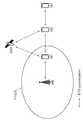
- Fig. 7is a view showing a structure of a side link to which one example of the present specification is applied.
- FIG. 8is a diagram showing an example of a scenario to which a side link is applied.
- FIG. 9is a diagram showing a mapping relationship between channels related to a side link.
- FIG. 10shows an example of a resource pool for side link (SL) communication.
- FIG. 11shows another example of a resource pool for side link (SL) communication.
- FIG. 12shows an example of decoding a radio signal on the basis of a reception window in a receiving UE.
- 13is a diagram showing the relationship between the reception window and the CP length of a radio signal.
- FIG. 14is a diagram for explaining a problem that occurs when receiving a plurality of received signals.
- 16shows a flow chart of a procedure according to an example of the present invention.
- FIG. 17is a diagram for explaining a procedure for performing synchronization performed in a terminal UE.
- 19shows an example of decoding of a radio signal through a preamble.
- FIG. 21shows an example of a transceiver according to an example of the present disclosure
- the technical features described belowcan be used in a communication standard by the 3rd Generation Partnership Project (3GPP) standardization organization or a communication standard by the Institute of Electrical and Electronics Engineers (IEEE) standardization.
- the communication specification by the 3GPP standardization organizationincludes the evolution of Long Term Evolution (LTE) and / or LTE systems.
- the evolution of LTE systemsincludes LTE-A (Advanced), LTE-A Pro, and / or 5G NR (New Radio).
- the communication standard by the IEEE standardization organizationincludes a wireless local area network system such as IEEE 802.11a / b / g / b / ac / ax.
- the above systemuses various multiple access technologies such as Orthogonal Frequency Division Multiple Access (OFDMA) and / or Single Carrier-Frequency Division Multiple Access (SC-FDMA) for uplink and / or downlink.
- OFDMAOrthogonal Frequency Division Multiple Access
- SC-FDMASingle Carrier-Frequency Division Multiple Access
- OFDMA and SC-FDMAmay be used for downlink and / or downlink.
- FIG. 1shows an example of a wireless communication system to which the technical features of the present specification can be applied.
- FIG. 1is an example based on an Evolved-Universal Terrestrial Radio Access Network (E-UTRAN).
- E-UTRANEvolved-Universal Terrestrial Radio Access Network
- the above-described LTEis part of E-UMTS (Evolved-UMTS) using Evolved-Universal Terrestrial Radio Access Network (E-UTRAN).
- the E-UTRANincludes a base station (BS) 20 that provides a user plane (UE) with a control plane and a user plane.
- the terminal 10may be fixed or mobile and may be a mobile station, a user terminal (UT), a subscriber station (SS), a mobile terminal (MT), a wireless device, It can be called a term.
- the base station 20is a fixed station that communicates with the terminal 10 and may be referred to as another term such as an evolved NodeB (eNB), a base transceiver system (BTS), an access point, or the like.
- eNBevolved NodeB
- BTSbase transceiver system
- access pointor the like.
- the base stations 20may be interconnected via an X2 interface.
- the base station 20is connected to an S-GW (Serving Gateway) through an MME (Mobility Management Entity) and an S1-U through an EPC (Evolved Packet Core) 30, more specifically, an S1-MME through an S1 interface.
- S-GWServing Gateway
- MMEMobility Management Entity
- EPCEvolved Packet Core
- the EPC 30is composed of an MME, an S-GW, and a P-GW (Packet Data Network-Gateway).
- the MMEhas information on the access information of the terminal or the capability of the terminal, and this information is mainly used for managing the mobility of the terminal.
- the S-GWis a gateway having an E-UTRAN as an end point
- the P-GWis a gateway having a PDN as an end point.
- FIG. 2shows another example of a wireless communication system to which the technical features of the present specification can be applied.
- FIG. 2is an example in which a 5G NR (New Radio) standard is utilized.
- the communication entity used in the 5G NR standard(hereinafter referred to as "NR" standard) absorbs some or all of the functions of the objects (eNB, MME, S-GW) introduced in FIG. 1, Or " ng ".
- the system of Fig. 2includes an NG-RAN (Radio Access Network) communicating with a UE (UE), and the NG-RANs 21 and 22 are entities corresponding to base stations and are connected to the gNB 21 or ng- ).
- a network interface called an Xn interfaceis defined between NG-RAN (21, 22) entities.
- the gNB 21provides an NR user plane and a control plane for the UE and accesses the 5GC (5G Core network) through the NG interface shown in Fig.
- the Ng-eNB 22is an entity providing a user plane and a control plane based on Evolved-Universal Terrestrial Radio Access (UTRA) for the UE.
- UTRAEvolved-Universal Terrestrial Radio Access
- the Access and Mobility Management Functionis an entity including the functions of the conventional MME and communicates with the NG-RANs 21 and 22 through the NG-C interface.
- the NG-C interfaceis the control plane interface between NG-RAN and AMF.
- the UPFUser Plane Function
- the NG-U interfaceis the user plane interface between NG-RAN and AMF.
- the layers of the Radio Interface Protocol between the networke.g., NG-RAN and / or E-UTRAN
- Layer 1Layer 2
- Layer 3Layer 3
- a physical layer belonging to a physical layerprovides an information transfer service using a physical channel and a radio resource control layer (RRC) located at a third layer controls a radio resource between a terminal and a network .
- RRCradio resource control layer
- the RRC layerexchanges RRC messages between the UE and the BS.
- one radio frameis composed of 10 subframes, and one subframe is composed of two 2 slots.
- the length of one subframemay be 1 ms and the length of one slot may be 0.5 ms.
- the time taken for one subframe to be transmittedis called a transmission time interval (TTI).
- TTImay be a minimum unit of scheduling.
- the NR standardsupports a variety of numerologies, and accordingly, the structure of the radio frame is varied.
- the NR standardsupports a number of subcarrier spacing in the frequency domain, where the neuronal logarithm of NR is determined by the neuronal logics used. Table 1 below lists a number of new genomes supported in NR. Each new locale is identified by an index " [mu] ".
- the subcarrier spacingcan be set to any one of 15, 30, 60, 120, and 240 kHz, but since specific values can be changed, each of the spacings (for example, (E.g., PUSCH (Physical Uplink Shared CHannel), PDSCH (PUSCH), and so on) according to subcarrier spacing, as shown in Table 1.
- the subcarrier spacingPhysical Downlink Shared CHannel) or the like). That is, user data transmission may not be supported only in at least one predetermined subcarrier spacing (for example, 240 kHz).
- synchronization channelse.g., a Primary Synchronization Signal (PSS), a Secondary Synchronization Signal (SSS), a Physical Broadcast CHannel (PBCH), etc.
- PSSPrimary Synchronization Signal
- SSSSecondary Synchronization Signal
- PBCHPhysical Broadcast CHannel
- the NR standardmay be set to a different number of slots and a different number of symbols depending on various new logics, i.e., various subcarrier spacing.
- a concrete examplemay be as shown in Table 2 below.
- 'symbol'refers to a signal transmitted during a specific time interval, for example, a signal generated by OFDM (Orthogonal Frequency Division Multiplexing) processing. That is, the symbols may be OFDM / OFDMA symbols, SC-FDMA symbols, or the like.
- a cyclic prefix (CP)may be located between each symbol.
- An example of Table 2may be an example in which a normal CP (cyclic prefix) is applied
- a frequency division duplex (FDD) and / or a time division duplex (TDD)may be applied to a wireless system to which one example of the present invention is applied.
- FDDfrequency division duplex
- TDDtime division duplex
- an uplink and a downlink subframeare allocated in units of subframes in the LTE system.
- NR standards / systemscan be divided into downlink (denoted by D), flexible (denoted by X), and uplink (denoted by U) in symbol units as shown in the following table.
- the contents of the following tablemay be commonly applied to specific cells, common to adjacent cells, or individually or differently applied to each UE.
- Table 4shows only a part of the format defined in the actual NR standard (i.e., the TDD format), and the specific allocation technique can be changed or added.
- the UEreceives a setup of a slot format (i.e., a TDD format) through an upper layer signal, a format of a slot through DCI (Downlink Control Information) transmitted through a PDCCH (Physical Downlink Control Channel) That is, the format of the slot can be set based on the combination of the RRC signal and the DCI.
- a slot formati.e., a TDD format
- DCIDownlink Control Information
- PDCCHPhysical Downlink Control Channel
- FIG. 5is a diagram showing an example of a resource grid.
- An example of FIG. 5is a time-frequency resource grid used in NR standards.
- An example of FIG. 5may be applied to the uplink and / or downlink.
- a number of slotsare included on the time axis.
- "14 ⁇ 2 ⁇ " symbolscan be expressed in the resource grid if expressed according to the value of " ⁇ ".
- one resource block (RB)can occupy 12 consecutive subcarriers.
- One resource blockmay be referred to as a physical resource block (PRB), and 12 resource elements (REs) may be included in each physical resource block.
- the number of allocatable resource blocks (RBs)may be determined based on a minimum value and a maximum value. Also, the number of allocatable resource blocks (RB) can be set individually according to the new router (" ⁇ "), and can be set to the same value for the uplink and the downlink, or can be set to different values.
- the UEmay perform cell search to acquire time and / or frequency synchronization with a cell and acquire a cell ID.
- Synchronization channelssuch as Primary Synchronization Signal (PSS), Secondary Synchronization Signal (SSS), and Physical Broadcast CHannel (PBCH) may be used for cell search.
- PSSPrimary Synchronization Signal
- SSSSecondary Synchronization Signal
- PBCHPhysical Broadcast CHannel
- PSS and SSSinclude one symbol and 127 subcarriers
- the PBCHcan be transmitted through three symbols and include 240 subcarriers.
- the PSSis used for SSB (Synchronization Signal / PBCH block) symbol timing acquisition and indicates three hypotheses for cell ID identification.
- the SSSis used for cell ID identification and indicates 336 hypotheses. Consequently, 1008 physical layer cell IDs can be configured through the PSS and the SSS.
- the SSB blockcan be repeatedly transmitted according to a predetermined pattern within a 5 ms window. For example, when L SSB blocks are transmitted, SSB # 1 through SSB # L all contain the same information, but they can be transmitted through beams in different directions. That is, the quasi co-location (QCL) may not be applied to the SSB blocks within the 5 ms window.
- the beam used to receive the SSB blockmay be used in subsequent operations (e.g., random access operations, etc.) between the terminal and the network.
- the SSB blockcan be repeated at a specific period. The repetition period can be set individually according to the neuromargraphy.
- the PBCHhas a bandwidth of 20 RB for the 2 nd symbol and 8 RB for the 3 nd symbol.
- a DM-RS for decoding the PBCHis included in the PBCH.
- the frequency domainis determined according to the cell ID value of the DM-RS.
- CRScell-specific RS
- a special DM-RSis defined for decoding the PBCH.
- the PBCH-DMRSmay include information indicating an SSB index.
- the PBCHperforms various functions, and typically can perform a function of broadcasting an MIB (Master Information Block).
- SIis divided into Minimum SI (MSI) and Other SI (OSI)
- Minimum SIcan be divided into MIB and SIB1 again, and Minimum SI excluding MIB is defined as RMSI (Remaining Minimum SI) Lt; / RTI >
- the MIBcontains information necessary for decoding SIB1 (System Information Type1). For example, subcarrier spacing applied to SIB1 (and message 2/4 used in the random access procedure, other system information (SI)), frequency offset between the SSB and the subsequently transmitted RB, The bandwidth of the PDCCH / SIB, and information for decoding the PDCCH (e.g., information on search-space / CORESET / DM-RS, etc., described later).
- SIB1is repeatedly transmitted through the PDSCH and includes control information for initial access of the UE and information for decoding another SIB.
- Fig. 7is a view showing a structure of a side link to which one example of the present specification is applied.
- an uplink (UL) and a downlink (DL)may be defined between the BS 710 and the MS 720.
- a side link SLis defined between the terminals 720.
- the side link SLcorresponds to the PC5 interface defined in the 3GPP standard.
- the resource allocated to the side link SLmay be selected from the UL resource. Specifically, a subframe (or a time resource such as a slot) on the UL frequency on the FDD or a subframe (or a time resource such as a slot) allocated on the TDD on the UL can be allocated.
- ProSe communication "may be used in a similar concept to the side link SL.
- ProSetypically refers to an end-to-end application, while a side link (SL) can refer to a channel structure.
- a structure related to a physical / transmission / logical channel used for an air interface for realizing a ProSe applicationis generally described by the concept of a side link SL.
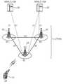
- FIG 8is a diagram showing an example of a scenario to which a side link is applied.
- the side link SL or ProSe communicationcan be divided into three scenarios.
- a networke.g., a base station
- UEtransmitting terminal
- RPresource pool
- out-of-coverage scenariosare where network control is not possible.
- the transmitting terminalcan perform side link (SL) communication through a preset resource (e.g., a resource preset via a USIM or a UICC card).
- an in-coverage UE and an out-of-coverage UEcoexist.
- the out-of-coverage UEuses a predetermined resource, and the in-coverage UE can perform communication through resources controlled by the network.
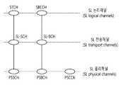
- a logical channel for the side link SLmay be defined as an SL Traffic Channel (STCH) for a data path and an SL Broadcast Control Channel (SBCCH) for control signaling.
- STCHis used to transmit user information for ProSe applications and is mapped to SL Shared Channel (SL-SCH) and Physical SL Shared Channel (PSSCH).
- the SBCCHis used for transmitting a control signal for synchronization and is mapped to SL-BCH (SL Broadcast Channel) and PSBCH (Physical SL Broadcast Channel).
- the Physical SL Control Channel (PSCCH)corresponds to the PDCCH of the cellular communication. Specifically, the PSCCH is used to transmit Sidelink Control Information (SCI), which is control information necessary for receiving and demodulating the PSSCH, which is transmitted before the STCH data block is transmitted.
- SCISidelink Control Information
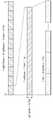
- FIG. 10shows an example of a resource pool for side link (SL) communication.
- SLside link
- FIG. 10shows an example in which a resource pool is set in units of subframes.
- the illustrated subframemay be replaced with another time unit (e.g., slot, symbol, or TTI).
- TTItime unit
- itcan be indicated according to the sub-frame bit map 1000 whether or not the corresponding sub-frame is used for the side link SL.
- the pattern displayed in accordance with the subframe bitmap 1000may be repeated.
- two frequency resourcescan be allocated for a side link SL in one subframe, and each frequency resource can be expressed in PRB (Physical Resource Block) units. Specifically, one frequency resource starts from PRB_start, and the remaining one frequency resource ends at PRB_end, and each PRB can occupy PRB-Num.
- One terminalcan be configured to use only one of the resources for side link / ProSe communication or the resources for cellular communication.
- a Resource Pool (RP) for side link (SL) communicationcan be divided into a receiving RP (Rx RP) and a transmitting RP (Tx RP), and each resource pool (RP) . All transmission RPs (Tx RPs) may be connected to at least one receiving resource pool (Rx RP).
- the allocation method for the resource pool (RP)can be classified into Mode 1 and Mode 2.
- the base stationcan indicate resources in a specific resource pool (RP), and in Mode 2, the UE can select a specific resource pool (RP) and select resources from the set of allocated resource pools.
- the UEFor Mode 1, the UE must be in the RRC connection state, but Mode 2 can be operated in the RRC idle state or out of coverage state. A more detailed description thereof will be made based on Fig.
- FIG. 11shows another example of a resource pool for side link (SL) communication.
- UE1i.e., the transmitting UE
- UE2i.e., receiving UE
- a network equipmentsuch as a base station (eNB) transmits / receives a signal according to a communication method between UEs, it can also be regarded as a kind of UE.
- eNBbase station
- the UE 1transmitting UE can operate to select a resource unit corresponding to a specific resource in the resource pool RP and transmit the side link / D2D signal using the resource unit.
- UE2receiveiving UE configures a resource pool (RP) in which UE1 can transmit signals and detects a signal of UE1 in the resource pool (RP).
- the resource pool RPmay inform the base station if UE1 is in the coverage of the base station (i.e., in the case of in-coverage) and if the UE is outside the coverage of the base station (i.e., partial coverage or out of coverage) It may be informed or determined as a predetermined resource.
- a resource pool (RP)is composed of a plurality of resource units, and each UE can select one or a plurality of resource units and transmit its own side link / D2D signal.
- FIG. 11shows an example of a resource unit, where the total frequency resources are divided into N_F pieces and the total time resources are divided into N_T pieces to define a total of N_F * N_T resource units.
- the resource pool RP of FIG. 11is repeated in the cycle of the N_T subframe (or other time unit). That is, one resource unit can be periodically repeated as shown in FIG.
- an index of a physical resource unit to which one logical resource unit is mappedmay vary based on a predetermined pattern with time in order to obtain a diversity effect at a time and / or frequency dimension.
- a resource pool (RP) for side link / D2D communicationmay refer to a set of resource units that a UE (i.e., a transmitting UE) desiring to transmit a side link / D2D signal can use for transmission
- the Resource Pool (RP) described abovecan be subdivided into various kinds.
- the resource pool RPmay be divided into various types according to the content of the side link / D2D signal transmitted from each resource pool RP.
- the content of the D2D signalmay be divided as follows, and a separate resource pool (i.e., a separate or different resource pool) may be set for each.
- SAScheduling assignment
- the control channel described hereis a control channel that is used to transmit the resource position of the side link / D2D data channel that is trailing each transmission terminal or transmitted to the same time unit (e.g., subframe, TTI, slot, symbol) Is used for a signal including control information necessary for demodulation (e.g., at least one of information elements such as MCS, MIMO transmission method, timing advance, etc.). It is also possible that the above-mentioned signal can be transmitted multiplexed with the side link / D2D data on the same resource unit, in which case the SA resource pool means a pool for the resources to be transmitted multiplexed with the side link / D2D data.
- the SA control channelmay be referred to as a Sidelink / D2D control channel.
- the SAmay correspond to the PSCCH described in Fig.
- An individual resource pool RPmay be allocated to the side link / D2D data channel through which the transmitting terminal transmits the user data using the designated resource through the Scheduling assignment SA.
- the side link / D2D data channelmay correspond to the PSSCH described in FIG. If it is possible to multiplexly transmit with the side link / D2D data on the same resource unit, only the side link / D2D data channel except the SA information is transmitted in the resource pool (RP) for the side link / D2D data channel Can be a form. In other words, the resource element that was used to transmit the SA information on the individual resource unit in the SA resource pool (RP) is still used in the side link / D2D data channel RP to transmit the side link / D2D data.
- a message that the transmitting terminal transmits information such as its own ID and allows the neighboring UE to discover itselfis transmitted through a discovery channel or a physical sidelink discovery channel (PSDCH).
- PSDCHphysical sidelink discovery channel
- a separate resource pool (RP)may be allocated for that channel.
- the transmission timing determination method of the D2D signalfor example, whether it is transmitted at the reception timing of the synchronization reference signal or a predetermined timing advance therefrom) (For example, whether the base station assigns the transmission resource of an individual signal to an individual transmitting terminal or whether the individual transmitting terminal selects its own signal transmission resource in the pool), signal format (for example, the number of symbols occupied in the subframe, the number of subframes used for transmission of one D2D signal), signal strength from the base station, transmission power of the D2D UE, and the like.
- Mode 1a method in which the base station directly instructs the transmission resource of the transmitting terminal in the side link / D2D communication is referred to as Mode 1, and when the transmission resource region is set in advance or the base station designates the transmission resource region, A method for selecting a direct transmission resource may be referred to as Mode 2.
- D2D discoveryit is called Type 2 when the base station directly indicates the resource, and may be referred to as Type 1 when the UE directly selects the transmission resource in the preset resource region or the resource region indicated by the base station.
- An example of the present inventionproposes a method and apparatus for solving the problem that a wireless signal is not received due to propagation delay or the like.
- a problem that a radio signal can not be received due to propagation delay or the likewill be described.
- the existing sidelink transmissioncan be performed in such a manner that a plurality of radio signals are transmitted / received through different frequency resources after being synchronized with a common synchronization reference by a plurality of UEs .
- the above-mentioned "synchronization reference "will be described in more detail below, but may be, for example, a satellite signal such as a GNSS or a synchronization signal transmitted by a network entity such as a base station (eNB) Or a sidelink synchronization signal (SLSS) that is transmitted over the side link.
- the UEmay acquire synchronization and set a receiver window (RX window) based on a symbol boundary set through the acquired synchronization.
- the receiving windowmay be configured to receive (E.g., Fourier transform or FFT (Fast Fourier Transform) operation) on the received signal.
- the receiving windowmay be a decoding operation of a particular size (e.g., an FFT operation) And may correspond to a 2048-point FFT operation, for example.
- the receive windowmay correspond to a specific length of time (e.g., 1 ms) in the time domain. Specific Time unit can be set equal to the length (e.g., the above-described sub-frame unit, and symbols).
- the receiving UEmay perform decoding in such a manner as to perform a decoding operation based on the receiving window. That is, a decoding operation (for example, an FFT operation) is performed on a signal belonging to a reception window section of the entire received signal to determine whether the signal is normally decoded. If the received signal is normally decoded, Data can be transmitted to an upper layer or other parts of the terminal, and a NACK signal can be generated if the received signal is not normally decoded. That is, the receiving UE may decode the radio signal based on the receiving window and extract a signal received from the transmitting UE through a specific frequency resource.
- a decoding operationfor example, an FFT operation
- the time at which the transmitting UE (TX UE) starts transmittinghas a certain error from the symbol boundary derived from the above-mentioned " synchronization reference ".
- an error due to a propagation delay arriving from a transmitting UE (TX UE) to a receiving UE (RX UE)can be further applied.
- the radio signal from the transmitting UEcan reach the receiving UE at a time other than the symbol boundary derived from the above-mentioned " synchronous reference ".
- arrival points of respective radio signalsmay also be different. That is, a timing error may occur with respect to the received signal.
- the receiving UEmay perform a normal decoding operation (e.g., FFT operation) to orthogonally separate the intended signal from the unintended radio signal.
- a normal decoding operatione.g., FFT operation
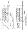
- the transmission signal of the transmitting UE1 1210may be positioned slightly ahead of the symbol boundary derived from the above-mentioned " synchronization reference ", and the transmitting signal of the transmitting UE2 1220 may be located behind.
- a signal from a transmitting UE 1210 or 1220can be reached to a receiving UE 1230 after a propagation delay on a radio channel .
- the arrival time error of the corresponding radio signalsis less than the length of the CP on the symbol boundary that the receiving UE 1230 derives / obtains from the synchronization reference 1240.
- the receiving UE 1230discards the portion corresponding to the CP and performs decoding on the subsequent portion, all the UE signals necessary for decoding are located in the receiving window. As a result, the UE can separate the orthogonal transmitting UE signals and complete decoding for each.
- the transmitting UE1 1210, the transmitting UE2 1220, and the receiving UE 1230may establish synchronization based on the same synchronization criterion 1240.
- the symbol boundary derived from the synchronization reference 1240is set as shown in Figure 12 where the distance between the transmitting UE1 1210 and the receiving UE 1230 is relatively close and the distance between the transmitting UE2 1220 and the receiving UE 1230
- the propagation delay for the first radio signal received at the receiving UE 1230 from the transmitting UE1 1210is relatively smaller and the propagation delay from the transmitting UE2 1220 to the receiving UE 1230 is relatively small
- the propagation delay for the second wireless signal received at the base stationmay be relatively large.
- the propagation delay for the first radio signal 1250 in the receiving UE 1230is relatively small and the propagation delay for the second radio signal 1260 is relatively large, as shown in FIG. 12 .
- the received first radio signal 1310may include at least one time unit (e.g., a symbol), and the time unit may include a first CP 1315.
- the time unitmay include a first CP 1315.
- the magnitude 1320 of the propagation delay applied to the first wireless signal 1310is shorter than the length of the first CP 1315, all information / bits of the first wireless signal 1310 are included in the reception window 1300, 1 wireless signal can be successfully decoded.
- the magnitude 1340 of the propagation delay for the second wireless signal 1330is greater than the length of the second CP 1335, some information / bits of the second wireless signal 1310 may be sent to the receiving window 1300 So that successful decoding at the receiving terminal may not be possible.
- the difference 1320 between the start point of the symbol boundary derived from the synchronization reference and the reception time point of the first radio signali.e., the reception start point
- the difference 1340 between the start point of the symbol boundary derived from the synchronization reference and the start point of the second radio signali.e., the start point of reception
- the size (or length) of the propagation delay and the length of the CPare closely related. If the CP length is set long enough, the problem of propagation delay can be prevented.
- the length of such a CPis generally determined according to the communication standard. Since the TTI (Transmission Time Interval) is relatively long in the conventional communication standard, the length of the CP is also set to be long. That is, since the TTI applied to the radio signal is conventionally set to be relatively long, the size of a time unit (for example, a symbol, a subframe, a slot, etc.) used for transmitting / receiving a radio signal is set to be relatively long . Accordingly, the length of the CP included in the specific time unit is set to be relatively long.
- TTITransmission Time Interval
- the length of the TTIis set shorter than that of the existing standard. Accordingly, the length of the CP for the side link in the high frequency band, for example, the millimeter wave (mmWave) band is likely to be shortened.
- a timing error of the radio signal received by the receiving UEfor example, Time error
- the decoding performance of the receiving UEmay be degraded.
- a bit / component of a desired signalis not included in one RX window set by the receiving UE, or an unintended signal (for example, Inter Symbol Interference) is included .
- an unintended signalfor example, Inter Symbol Interference
- orthogonalityis not guaranteed for each signal / channel, and interference (e.g., Inter Carrier Interference / ICI) may occur.
- FIG. 14is a diagram for explaining a problem that occurs when receiving a plurality of received signals.
- Fig. 14relates to an example in which a receiving UE and all transmitting UEs acquire synchronization via the same " synchronization reference ".
- the distance between the receiving UE and the transmitting UE1 / UE3is similar. Accordingly, the receiving UE can set one receiving window (e.g., RX window # 1 shown) and perform decoding based on one receiving window.
- one receiving windowe.g., RX window # 1 shown
- the receiving UEcan receive all the signals / bits necessary for the decoding operation (e.g., FFT operation). Accordingly, one receiving window for the first / third wireless signal can be set. However, since a relatively large delay is applied to the radio signal 1420 received from the transmitting UE2, the receiving UE sets only one receiving window (e.g., the illustrated RX window # 1) For example, FFT operation), reception performance degradation due to ICI / ISI may occur.
- the illustrated RX window # 1For example, FFT operation
- an example of the present disclosureproposes a technique of setting a plurality of reception windows and performing decoding based on a plurality of reception windows.
- an example of FIG. 14is an example related to a propagation delay by a plurality of transmitting UEs transmitting at different positions. That is, the example of Fig. 14 relates to cases in which propagation delays of different sizes (i.e., different time lengths) are problematic. However, the problem with a single receive window can also occur for multiple radio signals with the same propagation delay. Specifically, if the first radio signal comprises a CP of a first length and the second radio signal comprises a CP of a second length (different from the first length), then the first and second radio signals, Even if the same propagation delay is applied, a plurality of receiving windows may be required.
- FIG. 15shows an example in which CPs of different lengths are applied to different radio signals.
- a receiving UE 1550receives a plurality of radio signals 1570, 1580.
- a plurality of radio signals 1570, 1580may be received from the same or different transmitting UEs, which are received from the same transmitting UE 1510 in the example of FIG.
- the plurality of radio signals 1570 and 1580 received by the receiving UEcorrespond to the plurality of radio signals 1530 and 1540 transmitted by the transmitting terminal 1510.
- the plurality of radio signals 1570 and 1580 received at the receiving UE 1550may be transmitted in different frequency bands (e.g., different transmission carriers). In this case, either one may be received over a first frequency band (e.g., below 6GHz band) and the other may be received over a second frequency band (e.g., above 6GHz band).
- the transmitting UE 1510 and the receiving UE 1550can acquire synchronization through the same " synchronization reference ". Accordingly, a symbol boundary 1520 derived through one " synchronization reference " can be set.
- the first wireless signals 1570may be applied / included in the first CPs 1531 and 1571 and the second wireless signals 1580 may be applied / included in the second CPs 1541 and 1581.
- the length of the first CPs 1531 and 1571may be longer than that of the second CPs 1541 and 1581.
- the same or different numerology or subcarrier spacingmay be applied to the first radio signal 1570 and the second radio signal 1580.
- the first CPs 1531 and 1571 and the second CPs 1541 and 1581may be derived from the same sequence (or a different sequence having the same bit length) having the same bit length.
- the same (or substantially the same) propagation delaymay be applied to the first radio signal 1570 and the second radio signal 1580 received at the receiving UE 1550 of FIG. However, if the magnitude of the propagation delay is greater than the length of the second CP 1581, the receiving UE 1550 preferably sets a plurality of receiving windows.
- the length of the first CP 1571is set longer than the length of the second CP 1581, even if only a single reception window 1590 is set, all bits / information of the first wireless signal are received Window 1590. < / RTI > That is, since the difference between the start time of the reception window 1590 and the reception time (arrival time) of the first radio signal 1570 is less than the length of the first CP 1571, (1570).
- the receiving UEsets a plurality of receiving windows, and the start times of the plurality of receiving windows are set to be different from each other. That is, it is preferable that a plurality of reception windows are partially overlapped in the time domain.
- 16shows a flow chart of a procedure according to an example of the present invention.
- the receiving UEacquires synchronization for the side link (S1610). Thereafter, the receiving UE receives a plurality of radio signals (e.g., first / second radio signals) through the side link (S1620).
- a first CPmay be applied / included in the first wireless signal
- a second CPmay be applied / included in the second wireless signal.
- the receiving UEmay set a plurality of receiving windows in the receiving UE to decode the 1/2 wireless signal (S1630).
- the starting points of the plurality of reception windowsmay be set differently from each other. In other words, a plurality of receive windows may be partially overlapped in the time domain.
- the receiving UEmay perform decoding on the first radio signal and the second radio signal based on the plurality of reception windows (S1640).
- the step S1610may use some of the synchronization-related features described below. That is, the transmitting UE and the receiving UE can acquire synchronization from one " synchronization reference " according to the following method, and thereby specify the symbol boundary.
- the receiving UEdoes not need to specify different symbol boundaries for the above-mentioned plurality of radio signals (first / second radio signals). Accordingly, the time synchronization acquired by the receiving UE can be commonly applied to a plurality of radio signals (first / second radio signals).
- the " synchronization reference "may be a common one, but an example of the present specification is not limited thereto.
- the " synchronization reference "may be different from each other.
- a UE 1e.g., a transmitting UE or a receiving UE, and may be an LTE V2X UE or an NR V2X UE, like other UEs described herein
- UE2e.g., UE may be a UE or a receiving UE and, like other UEs described herein, may be an LTE V2X UE or an NR V2X UE
- the UE 1may be a sync reference for transmitting SLSS, which will be described later, while operating on the basis of a GNSS (or eNB, gNB, LTE UE) synchronization criterion described later.
- the UE2may not acquire the GNSS signal, and in this case, the UE2 may perform synchronization based on the SLSS transmitted by the UE1. Consequently, the synchronization criterion of UE2 (i.e., the direct synchronization criterion) may be UE1 operating on the GNSS (or eNB / gNB) basis.
- UE1 and UE2may be treated as different direct synchronization criteria, but if UE2 successfully decodes the SLSS of UE1, then the symbol boundaries obtained by UE1 and UE2 will be identical to each other. Accordingly, in the example of this specification, the number of " synchronization reference " is not limited to one.
- SLIDSystemlink Synchronization Signal
- PSSSPrimary Sidelink Synchronization Signal
- SSSSSecondary Sidelink Synchronization Signal
- PSBCHPhysical SL Broadcast Channel
- SLBCSL Broadcast Control Channel
- the synchronization source for the side linkmay vary depending on the state of the terminal. That is, the synchronization source may be set differently depending on whether the terminal is an in-coverage (INC) terminal or an out-of-coverage (OOC) terminal.
- IOCin-coverage
- OOCout-of-coverage
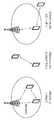
- FIG. 17is a diagram for explaining a procedure for performing synchronization in a UE.
- a UE 1is a terminal (INC UE) in a cell coverage of a base station (eNB), and can directly synchronize with a base station by receiving signals necessary for synchronization from the base station.
- the BSmay be referred to as a synchronization reference for the UE 1 and the UE 1 may be referred to as being directly synchronized with the BS.
- the UE 1may directly receive a signal necessary for synchronization from the Global Navigation Satellite System (GNSS) to perform synchronization with the GNSS.
- GNSSGlobal Navigation Satellite System
- the GNSSmay be referred to as a synchronization reference for the UE 1 (UE1), and the UE 1 (UE1) may be expressed as being directly synchronized with the GNSS.
- the UE 1may transmit SLSS and / or PSBCH for other UEs after synchronizing with the BS or the GNSS.
- the UE 2is an OOC UE located outside the cell coverage of the base station and can directly receive a signal necessary for synchronization from the GNSS to perform synchronization with the GNSS.
- the GNSScan be referred to as a synchronization reference for the UE2 (UE2).
- the terminal 2 (UE2)may receive a signal necessary for synchronization from the terminal 1 (UE1) and perform synchronization.
- the UE2 (UE2)may transmit the SLSS and / or PSBCH for the other UE after synchronization with the GNSS or the UE1 (UE1).
- the UE 3is a UE located outside the cell coverage of the BS, and can receive synchronization signals from the UE 2 to perform synchronization.
- the terminals 1, 2, and 3may be side link terminals / V2X terminals supporting side links.
- An OOC UEsuch as UE2, may perform an SLSS (/ PSBCH) transmission operation and, for this, an SLSS (/ PSBCH) resource may be set.
- an SLSS (/ PSBCH) resourcemay be set.
- the OOC terminalhaving the synchronization channel reference resource based on the global satellite navigation system (GNSS)
- GNSSglobal satellite navigation system
- the SLSS / PSBCH resource used when the terminal 2 receives the SLSS / PSBCH and transmits / relays the SLSS / PSBCH, and the SLSS / PSBCH after synchronizing with the GNSS, SLSS / PSBCH resourcescan be set / signaled differently or independently.
- the receiving UEcan receive a plurality of radio signals (e.g., first / second radio signals) via the side link.
- the receiving UEsets a plurality of receiving windows through step S1630.
- each of the plurality of receive windowsmay correspond to a particular size of a decoding operation (e.g., an FFT operation) and may correspond to, for example, a 2048-point FFT operation.
- each of the reception windowsmay correspond to a specific length of time (for example, 1 ms) in the time domain.
- reception windowmay be set equal to the length of a specific time unit (for example, the above-described subframe, unit, symbol).
- Each of the plurality of reception windowsmay have the same length.
- the step of setting a plurality of receiving windowsincludes determining a starting point of a plurality of receiving windows.
- a receiving UE performing step S1630may set a plurality of receiving windows " partially overlapped with the time axis ". In this case, each receive window can be shifted (1) evenly spaced along the time axis, and (2) transitioned at non-uniform intervals.
- a first wireless signal 1810 and a second wireless signal 1820may be received.
- a first CP 1815may be included / applied to the first wireless signal 1810 and a second CP 1825 may be included / applied to the second wireless signal 1820.
- the receiving UE performing step S1630may set up a plurality of receiving windows 1831, 1832, 1833 and 1834. [ Each of the plurality of receive windows 1831, 1832, 1833, 1834 shown may be commonly used for decoding the first wireless signal 1810 and the second wireless signal 1820. The number of specific receiving windows shown, the length of the signal, etc. may be changed.
- the receiving UEscan place the receiving windows 1831, 1832, 1833, 1834 at equal intervals.
- the difference between the starting points of the receiving windows 1831, 1832, 1833 and 1834i.e., the shift value applied to the receiving window
- the difference between the starting points of the receiving windows 1831, 1832, 1833 and 1834is the same as that of the first CP 1815 and the second CP 1825 .
- FIG. 18relates to the situation of receiving two radio signals 1810 and 1820, but the number of received radio signals may be three or more.
- the difference in starting point of the receiving windowmay be the smallest length among the CPs included / applied to three or more radio signals. As described in FIGS.
- the terminalwhen the reception window is changed by the length of the CP, the terminal can receive all the signals necessary for decoding.
- Information on the lengths of the first CP 1815 and the second CP 1825may be provided in advance or provided in the form of assist information as will be described later or may be provided on a channel through which the first wireless signal 1810 is received It can be received in advance.
- the difference between the start points of all the reception windowsis determined as the minimum CP.
- the present inventionis not limited thereto.
- the difference in starting points of a plurality of windowsmay be a certain multiple of the CP length (for example, CP length * arbitrary integer n).
- a plurality of receive windows 1831, 1832, 1833, 1834may be arranged at CP length intervals, but some of the plurality of receive windows may be omitted, resulting in a non-uniform placement of the plurality of receive windows Do.
- the receiving UEcan confirm that the radio signal will not arrive in a specific time interval based on the " assist information " which will be described later. In this case, it is possible to omit the corresponding at least one receiving window.
- the receiving UEreceives additional control information (hereinafter referred to as " assist information ") for the first and second radio signals 1810 and 1820, Quot;), it is possible to optimize the position of each reception window and the arrangement of the entire reception window.
- the receiving UEmay determine whether there is " assist information " such as distance related information between the receiving UE and the transmitting UE (e.g., timing gap between arrival time of the first / second radio signal and OFDM symbol boundary) 1832, 1833, 1834 depending on the type and / or type of the receiving window 1831, 1832, 1833, 1834.
- the receiving UEmay also be configured to determine the presence or absence of a shift value on a predetermined time axis (or signaled) and / or the number of receivable windows that it can set (maximum) and /
- the arrangement of the entire receiving windowcan be optimized in consideration of the number and / or the CP length (or the difference in CP length) of the channel / signal (s)
- the receiving UEmay receive a plurality of receiving windows 1831, 1832, 1833, 1833, 1834). Described " assist information " may be received over the channel on which the first wireless signal 1810 is received.
- the spacing of the receive windows 1831, 1832, 1833, 1834may be set non-uniformly.
- the receiving UEcan arrange the receiving window so that reception can be performed intensively for a specific time interval based on the channel information, and such channel information can be obtained through " assist information ".
- the " (maximum) number of receiving windows " that can be set in the receiving UEcan be defined as a type of receiving capability information of the corresponding UE.
- the receiving UEcan report information on how many (maximum) several receiving windows can be used on one carrier, to the network or the like as its receiving capability information.
- the receiving UEcan report the receiving capability information to the network in the in-coverage state described in Fig. After the receiving UE reports the receiving capability information to the network, the receiving UE receives allocation information (information on the number of receiving windows, position and the like) for a plurality of receiving windows from the network and sets a plurality of receiving windows based on the received information .
- the receiving UEmay also report the receiving capability information based on a related service priority for the received radio signal. For example, it is also possible to receive placement information for a plurality of reception windows from the network only when receiving a high-priority service.
- the carrierrefers to a radio resource for transmitting the first radio signal 1810 and / or the second radio signal 1820.
- the carriermay be defined as a cell in the conventional LTE standard or an NR standard A bandwidth part (BWP) or a group of a predetermined number of subcarriers.
- the reception capability information regarding the " (maximum) number of reception windows "can be calculated based on (1) the number of carriers the receiving UE is receiving, and / or (2) the computing capability Such as the maximum number of RBs that can be decoded on a carrier. For example, if the receiving UE is receiving a channel / signal on a small number of carriers, the UE may concentrate its FFT processing power on a particular carrier. In other words, more RX window can be set for a specific carrier to be used for channel / signal reception.
- the receiving UEmay determine the number of receiving windows actually used by the receiving UE in consideration of some or all of the following. For example, the receiving UE may determine the number (or specific placement) of the receiving windows based on the new channel applied to the wireless signal (or channel) or subcarrier spacing, and the target range of the receiving service ) And / or " time synchronization error " and the like. For example, in the case of a target range, the receiving UE can obtain the (maximum) distance between the receiving UE and the transmitting UE by acquiring information on the service ID, service requirement, etc., It is possible to predict the maximum propagation delay that can be applied.
- the networkcan configure / preconfigure a relatively small number of RX window settings for UEs that are receiving or receiving a short target range of service.
- a relatively long CPmay be set / applied / included in the first radio signal, and the first radio signal may be received in the first frequency band (e.g., below 6GHz band).
- a relatively short CPmay be set / applied / included in the second wireless signal and the second wireless signal may be received in the second frequency band (e.g., above 6GHz band).
- the first radio signal and the second radio signalmay be classified according to the frequency band and / or the CP length.
- the first radio signal and the second radio signalmay be distinguished according to the contents of the information transmitted by the corresponding signal.
- the first wireless signalmay comprise a discovery channel that is either SLSS, PSBCH, or PSCCH, or periodically transmitted.
- the second wireless signalmay be a data transmission channel / signal (e.g., PSSCH).
- PSSCHdata transmission channel / signal
- the first and second radio signalscan be distinguished by considering both the length of the corresponding CP and the contents of the information. For example, a relatively long CP may be set / applied / included in the first radio signal, a data transmission channel / signal transmitted in the 6GHz band or less may be included, and a relatively short CP may be set / / And synchronization signals and / or control information transmitted over the 6 GHz band may be included.
- each radio signalmay include a predetermined preamble.
- the preamblemay be a signal generated through a predetermined bit sequence and may mean a signal capable of easily decoding a signal at a receiving UE.
- a receiving UEcan perform a decoding operation on a preamble to specify a time at which a decoding operation is to be performed, and performs a decoding operation (for example, an FFT operation) Can be performed.
- the transmitting UEsmay transmit a plurality of transmission signals 1910 and 1920 with a preamble, and the receiving UE may perform preamble detection on the received radio signals 1930 and 1940.
- the receiving UEcan detect reception timing errors of the individual signals / data (1930, 1940) through the preamble. In this case, the window size for preamble detection can be promised or signaled in advance considering possible (maximum) reception timing errors.
- the method of FIG. 19may be combined with a method of using a plurality of receive windows.
- the received timing error (gap) information for each detected data in the receiving UE (or network)may be determined by a single or multiple RX window setting method (e.g., RX window timing adjustment and / The number of RX windows to be set by the UE).
- the receiving UEcan remove the ICI based on the assist information, reduce the number of RX windows required for the ICI, and have an advantage of efficiently managing the processing power required for the FFT operation of the receiving UE .
- the same or different new logicsmay be applied to the first radio signal 1930 and the second radio signal 1940 of the plurality of radio signals according to the example of FIG.
- one of the plurality of radio signals 1930 and 1940may be received in a first frequency band (e.g., below 6GHz band) and the other may be received in a second frequency band (e.g., above 6GHz band ).
- a first frequency bande.g., below 6GHz band
- a second frequency bande.g., above 6GHz band
- the time length for transmitting the preamble included in the first radio signal 1930is preferably set to be equal to the time length for transmitting the preamble included in the second radio signal 1940.
- the length of the bit sequence generating each preamblemay be adjusted to determine It is also possible to set the time length of the preamble to be the same.
- an example of this specificationshows an example of a terminal (transmitting or receiving terminal / UE).
- a terminal 2000includes a processor 2010, a memory 2020, and a transceiver 2030.
- the illustrated processor, memory, and transceivermay each be implemented as separate chips, or at least two blocks / functions may be implemented through a single chip.
- the illustrated transceiver 2030performs transmission and reception of signals. Specifically, an operation of receiving the first and second radio signals is performed.
- the transceiver 2030may also perform decoding operations (e.g., FFT operations) based on the receive window set by the processor 2010.
- the transceiver 2030may include a receive window control (not shown) for extracting a portion of the received signal, and may include a decoding operation processor (not shown) for performing a decoding operation on the signal extracted through the receive window .
- the processor 2010may implement the functions, processes, and / or methods suggested herein. Specifically, the processor 2010 determines the number / arrangement of reception windows for the second wireless signal based on the first wireless signal acquired through the transceiver 2030, and transmits the determined information to the transceiver 2030 .
- the processor 2010may include an application-specific integrated circuit (ASIC), another chipset, a logic circuit, and a data processing device.
- Memory 2020can include read-only memory (ROM), random access memory (RAM), flash memory, memory cards, storage media, and / or other storage devices.
- the transceiver 110includes a transmitting part 111 and a receiving part 112.
- the transmission part 111includes a DFT (Discrete Fourier Transform) unit 1111, a subcarrier mapper 1112, an IFFT unit 1113, a CP insertion unit 11144, and a radio transmission unit 1115.
- the transmitting part 111may further include a modulator.
- the apparatusmay further include a scramble unit, a modulation mapper, a layer mapper, and a layer permutator, for example. Which may be arranged in advance of the DFT unit 1111.
- the transmitting part 111passes information through a DFT 1111 before mapping a signal to a subcarrier.
- a signal spreading (or precoded in the same sense) by the DFT unit 1111is subcarrier-mapped through the subcarrier mapper 1112 and then transmitted through an IFFT (Inverse Fast Fourier Transform) unit 1113, Signal.
- IFFTInverse Fast Fourier Transform
- the DFT unit 1111performs DFT on the input symbols to output complex-valued symbols. For example, when Ntx symbols are input (where Ntx is a natural number), the DFT size (size) is Ntx.
- the DFT unit 1111may be referred to as a transform precoder.
- the subcarrier mapper 1112maps the complex symbols to subcarriers in the frequency domain. The complex symbols may be mapped to resource elements corresponding to resource blocks allocated for data transmission.
- the subcarrier mapper 1112may be referred to as a resource element mapper.
- the IFFT unit 1113performs IFFT on the input symbol and outputs a baseband signal for data, which is a time domain signal.
- the CP inserting unit 1114copies a part of the rear part of the base band signal for data and inserts it in the front part of the base band signal for data.
- ISIInter-symbol interference
- ICIinter-carrier interference
- the receiving part 112includes a wireless receiving unit 1121, a CP removing unit 1122, an FFT unit 1123, and an equalizing unit 1124.
- the wireless receiving unit 1121, the CP removing unit 1122 and the FFT unit 1123 of the receiving part 112are connected to the wireless transmitting unit 1115, the CP inserting unit 1114, the IFF unit 1113 ). ≪ / RTI >
- the receiving part 112may further include a demodulator.
- the transceiver of FIG. 21may include a receiving window control unit (not shown) for extracting a part of a received signal, in addition to the illustrated block, and may include a decoding operation processing unit (not shown) for performing a decoding operation on a signal extracted through the receiving window ).
Landscapes
- Engineering & Computer Science (AREA)
- Signal Processing (AREA)
- Computer Networks & Wireless Communication (AREA)
- Mobile Radio Communication Systems (AREA)
Abstract
Description
Translated fromKorean본 명세서는 사이드링크를 지원하는 무선 통신 시스템에 관련된 것으로, 보다 구체적으로는 사이드링크 상에서 사용되는 무선 신호가 지연되는 경우 이를 처리하는 개선된 통신 기법에 관한 방법 및 장치를 제안한다. The present disclosure relates to wireless communication systems supporting side links, and more particularly, to a method and apparatus for improved communication techniques for dealing with delayed radio signals used on a side link.
ITU-R(International Telecommunication Union Radio communication sector)에서는 3세대 이후의 차세대 이동통신 시스템인 IMT(International Mobile Telecommunication)-Advanced의 표준화 작업을 진행하고 있다. IMT-Advanced는 정지 및 저속 이동 상태에서 1Gbps, 고속 이동 상태에서 100Mbps의 데이터 전송률로 IP(Internet Protocol) 기반의 멀티미디어 서비스 지원을 목표로 한다.In the International Telecommunication Union Radio Communication Sector (ITU-R), standardization of International Mobile Telecommunication (IMT) -Advanced, a next generation mobile communication system after 3rd generation, is under way. IMT-Advanced aims to support IP (Internet Protocol) based multimedia service at data rates of 1Gbps in a stationary and low-speed moving state and 100Mbps in a high-speed moving state.
3GPP(3rd Generation Partnership Project)는 IMT-Advanced의 요구 사항을 충족시키는 시스템 표준으로 OFDMA(Orthogonal Frequency Division Multiple Access)/SC-FDMA(Single Carrier-Frequency Division Multiple Access) 전송방식 기반인 LTE(Long Term Evolution)를 개선한 LTE-Advanced(LTE-A)를 준비하고 있다. LTE-A는 IMT-Advanced를 위한 유력한 후보 중의 하나이다.The 3rd Generation Partnership Project (3GPP) is a system standard that meets the requirements of IMT-Advanced. It is based on Long Term Evolution (LTE) based on Orthogonal Frequency Division Multiple Access (OFDMA) / Single Carrier-Frequency Division Multiple Access (SC- LTE-Advanced (LTE-A) is being prepared. LTE-A is one of the strong candidates for IMT-Advanced.
한편, 최근 장치들 간 직접통신을 하는 사이드링크(Sidelink) 또는 D2D (Device-to-Device)기술에 대한 관심이 높아지고 있다. 특히, 사이드링크 또는 D2D는 공중 안전 네트워크(public safety network)을 위한 통신 기술로 주목 받고 있다. 상업적 통신 네트워크는 빠르게 LTE로 변화하고 있으나 기존 통신 규격과의 충돌 문제와 비용 측면에서 현재의 공중 안전 네트워크는 주로 2G 기술에 기반하고 있다. 이러한 기술 간극과 개선된 서비스에 대한 요구는 공중 안전 네트워크를 개선하고자 하는 노력으로 이어지고 있다.On the other hand, there is a growing interest in a side link (sidelink) or a device-to-device (D2D) technology for direct communication between devices. In particular, the side link or D2D is attracting attention as a communication technology for a public safety network. Commercial telecommunication networks are rapidly changing to LTE, but current public safety networks are mainly based on 2G technology in terms of conflicts with existing telecommunications standards and cost. These technological gaps and demands for improved services have led to efforts to improve public safety networks.
공중 안전 네트워크는 상업적 통신 네트워크에 비해 높은 서비스 요구 조건(신뢰도 및 보안성)을 가지며 특히 셀룰러 통신의 커버리지가 미치지 않거나 이용 가능하지 않은 경우에도, 장치들 간의 직접 신호 송수신 즉, 사이드링크(또는 D2D) 동작도 요구하고 있다.The public safety network has higher service requirements (reliability and security) than a commercial communication network, and can be used to send and receive signals directly between devices, i.e., a side link (or D2D), even if the coverage of the cellular communication is insufficient or unavailable. It also requires operation.
사이드링크(또는 D2D) 동작은 근접한 기기들 간의 신호 송수신이라는 점에서 다양한 장점을 가질 수 있다. 예를 들어, D2D 단말은 높은 전송률 및 낮은 지연을 가지며 데이터 통신을 할 수 있다. 또한, D2D 동작은 기지국에 몰리는 트래픽을 분산시킬 수 있으며, D2D 단말이 중계기 역할을 한다면 기지국의 커버리지를 확장시키는 역할도 할 수 있다.The side link (or D2D) operation may have various advantages in that it transmits and receives signals between nearby devices. For example, the D2D terminal has high data rate and low delay and is capable of data communication. In addition, the D2D operation can distribute traffic to the base station, and can expand the coverage of the base station if the D2D terminal functions as a repeater.
상술한 사이드링크(또는 D2D) 통신을 확장하여 차량 간의 신호 송수신에 적용할 수 있으며, 차량(VEHICLE)과 관련된 통신을 특별히 V2X(VEHICLE-TO-EVERYTHING) 통신이라고 부른다. The side link (or D2D) communication described above can be extended to apply to the transmission / reception of signals between vehicles, and the communication related to VEHICLE is specifically called V2X (VEHICLE-TO-EVERYTHING) communication.
V2X에서 'X'라는 용어는 보행자(PEDESTRIAN), 차량(VEHICLE), 인프라스트럭쳐/네트워크(INFRASTRUCTURE/NETWORK) 등이 될 수 있으며, 차례로 V2P, V2V, V2I/N으로 표시할 수 있다.In V2X, the term 'X' can be PEDESTRIAN, VEHICLE, INFRASTRUCTURE / NETWORK, etc., and in turn V2P, V2V, V2I / N.
사이드링크를 통해 수신 UE가 무선 신호를 수신하는 경우, 종래의 수신 윈도우를 사용하여 디코딩을 수행하는 경우 다양한 문제가 발생할 수 있다. 예를 들어, 송신 UE가 하나인 경우, 송신 UE와 수신 UE 사이의 거리로 인한 전파 지연(propagation delay)의 크기가 수신된 무선 신호에 적용/포함된 CP(cyclic prefix)의 길이보다 큰 경우, 다양한 문제가 발생할 수 있다. 예를 들어, 송신 UE/수신 UE가 각각 하나이고, 전파 지연(propagation delay)의 크기가 CP의 길이보다 큰 경우, 수신 윈도우의 시작 시점을 개선하지 않고, 단일의 수신 윈도우를 사용한다면 디코딩이 어려울 수 있다. 이에 후술하는 본 명세서의 일례는 수신 윈도우의 시작 시점을 효율적으로 결정하거나, 수신 윈도우의 개수를 효율적으로 결정하여 디코딩의 성능을 개선할 수 있다. When a receiving UE receives a radio signal through a side link, various problems may occur when decoding is performed using a conventional receiving window. For example, when there is one transmitting UE, if the size of the propagation delay due to the distance between the transmitting UE and the receiving UE is greater than the length of the cyclic prefix (CP) applied / included in the received radio signal, Various problems may arise. For example, if the size of the propagation delay is larger than the length of the CP, it is difficult to decode if a single receive window is used without improving the start time of the receive window. . An embodiment of the present invention described below can improve the decoding performance by efficiently determining the start time of the reception window or efficiently determining the number of reception windows.
또한, 수신 UE가 서로 다른 특성(예를 들어, 후술하는 본 명세서의 일례에서 설명한 바와 같이, 서로 다른 뉴머럴로지, 서브캐리어 스페이싱, CP 길이, 시간 유닛의 길이, 및/또는 주파수 대역)을 가지는 복수의 무선 신호를 수신하는 경우에도, 수신 UE가 종래 기술에 따른 수신 윈도우를 사용하여 모든 신호를 디코딩하는데 문제가 발생할 수 있다. 예를 들어, 복수의 무선 신호에 대해서는 서로 다른 지연이나 오차가 발생하기 때문에, 수신 UE가 종래의 기법에 따르는 경우, 정상적인 디코딩을 할 수 없는 문제가 발생할 수 있다. 또한, 복수의 무선 신호에 대해서 동일한 지연이나 오차가 발생하더라도, 복수의 무선 신호의 특성이 서로 다르기 때문에, 정상적인 디코딩을 할 수 없는 문제가 발생할 수 있다.It is also possible for the receiving UE to have different characteristics (e.g., different genres, subcarrier spacing, CP length, length of time unit, and / or frequency band as described in the example of this specification, Even when a plurality of radio signals are received, a problem may arise in that the receiving UE decodes all the signals using the receiving window according to the prior art. For example, since different delays or errors arise for a plurality of radio signals, if the receiving UE follows the conventional technique, a problem that normal decoding can not be performed can occur. In addition, even if the same delay or error occurs in a plurality of radio signals, since the characteristics of a plurality of radio signals are different from each other, a problem that normal decoding can not be performed may occur.
본 명세서의 일례는 서로 다른 특성을 가지는 복수의 무선 신호를 디코딩하는 기법을 제안한다. 예를 들어, 복수의 무선 신호는 서로 다른 CP 길이를 가지거나 서로 다른 주파수 대역으로 수신되거나 서로 다른 채널로 구성될 수 있다. 본 명세서의 일례는 특정한 무선 신호를 기초로 복수의 수신 윈도우를 사용하여 디코딩을 수행하는 일례를 제안한다. One example of the present disclosure proposes a technique for decoding a plurality of radio signals having different characteristics. For example, the plurality of wireless signals may have different CP lengths, be received in different frequency bands, or be composed of different channels. An example of the present disclosure proposes an example of performing decoding using a plurality of reception windows based on a specific radio signal.
본 명세서의 일례에 따른 방법은, 사이드링크(sidelink)를 통해 신호를 수신하는 수신 단말을 위한 방법에 관련된다. 예를 들어, 수신 단말은 상기 사이드링크를 위한 동기(synchronization)를 획득할 수 있다. 이후, 수신 단말은 사이드링크를 통해 제1 무선 신호 및 제2 무선 신호를 수신하되, 상기 제1 무선 신호는 제1 CP(cyclic prefix)를 포함하고, 상기 제2 무선 신호는 제2 CP를 포함할 수 있다. 또한, 상기 제1 무선 신호 및 제2 무선 신호를 디코드(decode)하기 위해, 상기 수신 단말은 복수의 수신 윈도우를 설정하되, 상기 복수의 수신 윈도우의 시작 시점은 서로 다르게 설정될 수 있다. 또한, 상기 수신 단말은 상기 복수의 수신 윈도우를 기초로 상기 제1 무선 신호 및 제2 무선 신호에 대한 디코딩(decoding)을 수행할 수 있다.A method according to an example of the present disclosure relates to a method for a receiving terminal that receives a signal via a sidelink. For example, the receiving terminal may obtain synchronization for the side link. Thereafter, the receiving terminal receives a first radio signal and a second radio signal via a side link, the first radio signal including a first CP (cyclic prefix), and the second radio signal including a second CP can do. In order to decode the first wireless signal and the second wireless signal, the receiving terminal sets a plurality of receiving windows, and the starting points of the plurality of receiving windows may be set to be different from each other. Also, the receiving terminal may perform decoding on the first wireless signal and the second wireless signal based on the plurality of reception windows.
본 명세서의 일례는 복수의 무선 신호 중 CP의 길이가 짧게 형성되는 무선 신호를 기초로 복수의 수신 윈도우를 설정하는 기법을 제안한다. 이를 통해 고대역 신호에 CP의 길이가 짧게 설정되더라도, 정상적인 디코딩을 수행할 수 있는 장점이 있다. An example of the present invention proposes a technique of setting a plurality of reception windows based on a wireless signal in which a length of a CP is shortened among a plurality of wireless signals. Thus, even if the length of the CP is set to be short in the high-band signal, there is an advantage that normal decoding can be performed.
도 1은 본 명세서의 기술적 특징이 적용될 수 있는 무선통신 시스템의 일례를 나타낸다.1 shows an example of a wireless communication system to which the technical features of the present specification can be applied.
도 2는 본 명세서의 기술적 특징이 적용될 수 있는 무선통신 시스템의 또 다른 일례를 나타낸다.2 shows another example of a wireless communication system to which the technical features of the present specification can be applied.
도 3은 특정한 뉴머럴러지가 적용되는 일례를 나타낸다.Figure 3 shows an example in which a particular neurological is applied.
도 4는 또 다른 뉴머럴러지가 적용되는 일례를 나타낸다.Fig. 4 shows an example in which another nutrition is applied.
도 5는 자원 그리드(resource grid)의 일례를 나타내는 도면이다.5 is a diagram showing an example of a resource grid.
도 6은 본 명세서의 일례에 적용되는 동기채널의 일례를 나타낸다.6 shows an example of a synchronization channel applied to an example of this specification.
도 7은 본 명세서의 일례가 적용되는 사이드링크의 구조에 관한 도면이다.Fig. 7 is a view showing a structure of a side link to which one example of the present specification is applied.
도 8은 사이드링크가 적용되는 시나리오의 일례를 나타낸 도면이다.8 is a diagram showing an example of a scenario to which a side link is applied.
도 9는 사이드링크에 관련된 채널 간의 매핑관계를 나타낸 도면이다.9 is a diagram showing a mapping relationship between channels related to a side link.
도 10은 사이드링크(SL) 통신을 위한 자원풀의 일례를 나타낸다.10 shows an example of a resource pool for side link (SL) communication.
도 11은 사이드링크(SL) 통신을 위한 자원풀의 또 다른 일례를 나타낸다.11 shows another example of a resource pool for side link (SL) communication.
도 12는 수신 UE에서 수신 윈도우를 기초로 무선 신호를 디코딩하는 일례를 나타낸다.12 shows an example of decoding a radio signal on the basis of a reception window in a receiving UE.
도 13은 수신 윈도우와 무선 신호의 CP 길이와의 관계를 나타내는 도면이다.13 is a diagram showing the relationship between the reception window and the CP length of a radio signal.
도 14는 다수의 수신 신호를 수신할 때 발생하는 문제점을 설명하는 도면이다.FIG. 14 is a diagram for explaining a problem that occurs when receiving a plurality of received signals.
도 15는 서로 다른 무선 신호에 서로 다른 길이의 CP가 적용되는 일례를 나타낸다.15 shows an example in which CPs of different lengths are applied to different radio signals.
도 16은 본 발명의 일례에 따른 절차흐름도를 나타낸다.16 shows a flow chart of a procedure according to an example of the present invention.
도 17은 단말(UE)에서 수행되는 동기화를 수행하는 절차를 설명하는 도면이다.FIG. 17 is a diagram for explaining a procedure for performing synchronization performed in a terminal UE.
도 18은 복수의 수신 윈도우를 설정되는 일례를 나타낸다.18 shows an example in which a plurality of reception windows are set.
도 19는 프리앰블을 통해 무선 신호에 대한 디코딩을 수행하는 일례를 나타낸다.19 shows an example of decoding of a radio signal through a preamble.
도 20은 본 명세서의 일례가 적용되는 단말의 일례를 나타낸다.20 shows an example of a terminal to which one example of the present specification is applied.
도 21은 본 명세서의 일례에 따른 트랜시버의 일례를 나타낸다.21 shows an example of a transceiver according to an example of the present disclosure;
이하에서 설명하는 기술적 특징은 3GPP(3rd Generation Partnership Project) 표준화 기구에 의한 통신 규격이나, IEEE(Institute of Electrical and Electronics Engineers) 표준화 기구에 의한 통신 규격 등에서 사용될 수 있다. 예를 들어, 3GPP 표준화 기구에 의한 통신 규격은 LTE(Long Term Evolution) 및/또는 LTE 시스템의 진화를 포함한다. LTE 시스템의 진화는 LTE-A(Advanced), LTE-A Pro, 및/또는 5G NR(New Radio)을 포함한다. IEEE 표준화 기구에 의한 통신 규격은 IEEE 802.11a/b/g/b/ac/ax 등의 무선랜(wireless local area network) 시스템을 포함한다. 상술한 시스템은 OFDMA(Orthogonal Frequency Division Multiple Access), 및/또는 SC-FDMA(Single Carrier-Frequency Division Multiple Access) 등의 다양한 다중접속기술을 상향링크 및/또는 하향링크에 사용한다. 얘를 들어, 하향링크에는 OFDMA 만을 사용하고 상향링크에는 SC-FDMA 만이 사용될 수도 있고, 하향링크 및/또는 하향링크에 OFDMA와 SC-FDMA가 혼용될 수도 있다.The technical features described below can be used in a communication standard by the 3rd Generation Partnership Project (3GPP) standardization organization or a communication standard by the Institute of Electrical and Electronics Engineers (IEEE) standardization. For example, the communication specification by the 3GPP standardization organization includes the evolution of Long Term Evolution (LTE) and / or LTE systems. The evolution of LTE systems includes LTE-A (Advanced), LTE-A Pro, and / or 5G NR (New Radio). The communication standard by the IEEE standardization organization includes a wireless local area network system such as IEEE 802.11a / b / g / b / ac / ax. The above system uses various multiple access technologies such as Orthogonal Frequency Division Multiple Access (OFDMA) and / or Single Carrier-Frequency Division Multiple Access (SC-FDMA) for uplink and / or downlink. For example, only OFDMA may be used for downlink, only SC-FDMA may be used for uplink, and OFDMA and SC-FDMA may be used for downlink and / or downlink.
도 1은 본 명세서의 기술적 특징이 적용될 수 있는 무선통신 시스템의 일례를 나타낸다. 구체적으로 도 1은 E-UTRAN(Evolved-Universal Terrestrial Radio Access Network)을 기반으로 하는 일례이다. 상술한 LTE는 E-UTRAN(Evolved-Universal Terrestrial Radio Access Network)을 사용하는 E-UMTS(Evolved-UMTS)의 일부이다.1 shows an example of a wireless communication system to which the technical features of the present specification can be applied. Specifically, FIG. 1 is an example based on an Evolved-Universal Terrestrial Radio Access Network (E-UTRAN). The above-described LTE is part of E-UMTS (Evolved-UMTS) using Evolved-Universal Terrestrial Radio Access Network (E-UTRAN).
E-UTRAN은 단말(10; User Equipment, UE)에게 제어 평면(control plane)과 사용자 평면(user plane)을 제공하는 기지국(20; Base Station, BS)을 포함한다. 단말(10)은 고정되거나 이동성을 가질 수 있으며, MS(Mobile station), UT(User Terminal), SS(Subscriber Station), MT(mobile terminal), 무선기기(Wireless Device), 스테이션(STA) 등 다른 용어로 불릴 수 있다. 기지국(20)은 단말(10)과 통신하는 고정된 지점(fixed station)을 말하며, eNB(evolved-NodeB), BTS(Base Transceiver System), 액세스 포인트(Access Point) 등 다른 용어로 불릴 수 있다.The E-UTRAN includes a base station (BS) 20 that provides a user plane (UE) with a control plane and a user plane. The terminal 10 may be fixed or mobile and may be a mobile station, a user terminal (UT), a subscriber station (SS), a mobile terminal (MT), a wireless device, It can be called a term. The
기지국(20)들은 X2 인터페이스를 통하여 서로 연결될 수 있다. 기지국(20)은 S1 인터페이스를 통해 EPC(Evolved Packet Core, 30), 보다 상세하게는 S1-MME를 통해 MME(Mobility Management Entity)와 S1-U를 통해 S-GW(Serving Gateway)와 연결된다.The
EPC(30)는 MME, S-GW 및 P-GW(Packet Data Network-Gateway)로 구성된다. MME는 단말의 접속 정보나 단말의 능력에 관한 정보를 가지고 있으며, 이러한 정보는 단말의 이동성 관리에 주로 사용된다. S-GW는 E-UTRAN을 종단점으로 갖는 게이트웨이이며, P-GW는 PDN을 종단점으로 갖는 게이트웨이이다.The
도 2는 본 명세서의 기술적 특징이 적용될 수 있는 무선통신 시스템의 또 다른 일례를 나타낸다. 구체적으로 도 2는 5G NR(New Radio) 규격이 활용되는 일례이다. 5G NR 규격(이하 “NR”규격)에 사용되는 통신 개체는 도 1에 소개된 개체(eNB, MME, S-GW)의 기능을 일부 또는 전부 흡수하는데, 종전 규격과의 구별을 위해 “NG” 또는 “ng”라는 명칭으로 식별될 수 있다.2 shows another example of a wireless communication system to which the technical features of the present specification can be applied. Specifically, FIG. 2 is an example in which a 5G NR (New Radio) standard is utilized. The communication entity used in the 5G NR standard (hereinafter referred to as "NR" standard) absorbs some or all of the functions of the objects (eNB, MME, S-GW) introduced in FIG. 1, Or " ng ".
도 2의 시스템은 단말(UE)과 통신하는 NG-RAN(Radio Access Network)을 포함하고, NG-RAN(21, 22)은 기지국에 대응되는 개체이며, gNB(21) 또는 ng-eNB(22)를 포함한다. NG-RAN(21, 22) 개체들 간에는 Xn 인터페이스라 불리는 네트워크 인터페이스가 정의된다. gNB(21)는 단말(UE)을 위한 NR 사용자 평면 및 제어 평면을 제공하고 도 2에 도시된 NG 인터페이스를 통해 5GC(5G Core network)에 접속한다. Ng-eNB(22)는 단말(UE)을 위해 UTRA(Evolved-Universal Terrestrial Radio Access) 기반의 사용자 평면과 제어 평면을 제공하는 개체로, NG 인터페이스를 통해 5GC에 접속한다.The system of Fig. 2 includes an NG-RAN (Radio Access Network) communicating with a UE (UE), and the NG-
AMF(Access and Mobility Management Function)는 종래의 MME의 기능을 포함하는 개체이며, NG-RAN(21, 22)과는 NG-C 인터페이스를 통해 통신한다. NG-C 인터페이스는 NG-RAN과 AMF 간의 제어 평면 인터페이스이다.The Access and Mobility Management Function (AMF) is an entity including the functions of the conventional MME and communicates with the NG-
UPF(User Plane Function)는 종래의 S-GW의 기능을 포함하는 개체이며, NG-RAN(21, 22)과는 NG-U 인터페이스를 통해 통신한다. NG-U 인터페이스는 NG-RAN과 AMF 간의 사용자 평면 인터페이스이다.The UPF (User Plane Function) is an entity including the functions of the conventional S-GW and communicates with the NG-
도 1 및/또는 도 2의 시스템 상에서, 네트워크(예를 들어, NG-RAN 및/또는 E-UTRAN)와 단말 사이의 무선인터페이스 프로토콜(Radio Interface Protocol)의 계층들은 통신시스템에서 널리 알려진 개방형 시스템간 상호접속 (Open System Interconnection; OSI) 기준 모델의 하위 3개 계층을 바탕으로 L1 (제1계층), L2 (제2계층), L3(제3계층)로 구분될 수 있는데, 이 중에서 제1계층에 속하는 물리계층은 물리채널(Physical Channel)을 이용한 정보전송서비스(Information Transfer Service)를 제공하며, 제3계층에 위치하는 RRC(Radio Resource Control) 계층은 단말과 네트워크 간에 무선자원을 제어하는 역할을 수행한다. 이를 위해 RRC 계층은 단말과 기지국간 RRC 메시지를 교환한다.On the system of Figure 1 and / or Figure 2, the layers of the Radio Interface Protocol between the network (e.g., NG-RAN and / or E-UTRAN) (Layer 1), Layer 2 (Layer 2), and Layer 3 (Layer 3) based on the lower three layers of the Open System Interconnection (OSI) reference model, A physical layer belonging to a physical layer provides an information transfer service using a physical channel and a radio resource control layer (RRC) located at a third layer controls a radio resource between a terminal and a network . To this end, the RRC layer exchanges RRC messages between the UE and the BS.
이하 물리채널을 통해 송수신되는 라디오 프레임의 구조를 설명한다.Hereinafter, a structure of a radio frame transmitted and received via a physical channel will be described.
LTE 규격(및 LTE 규격의 진화)에서는 하나의 라디오 프레임이 10개의 서브프레임(subframe)으로 구성되고, 하나의 서브프레임은 2개의 2개의 슬롯(slot)으로 구성되었다. 하나의 서브프레임의 길이는 1ms이고, 하나의 슬롯의 길이는 0.5ms 일 수 있다. 하나의 서브 프레임이 전송되는 데 걸리는 시간을 TTI(transmission time interval)이라 한다. TTI는 스케줄링의 최소 단위일 수 있다.In the LTE standard (and evolution of the LTE standard), one radio frame is composed of 10 subframes, and one subframe is composed of two 2 slots. The length of one subframe may be 1 ms and the length of one slot may be 0.5 ms. The time taken for one subframe to be transmitted is called a transmission time interval (TTI). The TTI may be a minimum unit of scheduling.
NR 규격은, LTE 규격과 다르게, 다양한 뉴머럴로지(numerology)를 지원하고, 이에 따라 라디오 프레임의 구조가 다양한 설정된다. NR 규격에서는 주파수 도메인 상에서 다수의 서브캐리어 스페이싱(subcarrier spacing)을 지원하는데, NR의 뉴머럴로지는 사용되는 뉴머럴로지에 의해 정해진다. 하기 표 1은 NR에서 지원되는 다수의 뉴머럴로지를 표시한다. 각각의 뉴머럴로지는 인덱스 “μ” 에 의해 식별된다.Unlike the LTE standard, the NR standard supports a variety of numerologies, and accordingly, the structure of the radio frame is varied. The NR standard supports a number of subcarrier spacing in the frequency domain, where the neuronal logarithm of NR is determined by the neuronal logics used. Table 1 below lists a number of new genomes supported in NR. Each new locale is identified by an index " [mu] ".
표 1에 표시된 바와 같이. 서브캐리어 스페이싱은 15, 30, 60, 120, 240 kHz 중에 어느 하나로 정해질 수 있으나, 구체적인 수치는 변경 가능하므로 각각의 스페이싱(예를 들어, μ=0, 1…4)은 제1, 제2, 내지 제5 서브캐리어 스페이싱(즉, N 서브캐리어 스페이싱)으로 표시될 수 있다.표 1에 표시된 바와 같이, 서브캐리어 스페이싱에 따라 사용자 데이터(예를 들어, PUSCH(Physical Uplink Shared CHannel), PDSCH(Physical Downlink Shared CHannel) 등)를 전송하는데 사용되지 않을 수 있다. 즉, 기 설정된 적어도 하나의 서브캐리어 스페이싱(예를 들어, 240 kHz)에서만 사용자 데이터 전송이 지원되지 않을 수 있다.As shown in Table 1. The subcarrier spacing can be set to any one of 15, 30, 60, 120, and 240 kHz, but since specific values can be changed, each of the spacings (for example, (E.g., PUSCH (Physical Uplink Shared CHannel), PDSCH (PUSCH), and so on) according to subcarrier spacing, as shown in Table 1. The subcarrier spacing Physical Downlink Shared CHannel) or the like). That is, user data transmission may not be supported only in at least one predetermined subcarrier spacing (for example, 240 kHz).
또한, 표 1에 표시된 바와 같이, 서브캐리어 스페이싱에 따라 동기채널(예를 들어. PSS(Primary Synchronization Signal), SSS(Secondary Synchronization Signal), PBCH(Physical Broadcast CHannel) 등)이 지원되지 않을 수 있다. 즉, 특정한 적어도 하나의 서브캐리어 스페이싱(예를 들어, 60 kHz)에서만 동기채널이 지원되지 않을 수 있다.In addition, as shown in Table 1, synchronization channels (e.g., a Primary Synchronization Signal (PSS), a Secondary Synchronization Signal (SSS), a Physical Broadcast CHannel (PBCH), etc.) may not be supported depending on the subcarrier spacing. That is, the synchronization channel may not be supported only in a specific at least one subcarrier spacing (for example, 60 kHz).
NR 규격은 다양한 뉴머럴로지, 즉 다양한 서브캐리어 스페이싱에 따라 포함되는 슬롯의 개수와 심볼의 개수가 다르게 설정될 수 있다. 구체적인 일례는 하기 표 2와 같을 수 있다.The NR standard may be set to a different number of slots and a different number of symbols depending on various new logics, i.e., various subcarrier spacing. A concrete example may be as shown in Table 2 below.
표 2에 따르면, “μ=0”인 제1 뉴머럴러지가 적용되는 경우, 하나의 라디오 프레임은 10개의 서브프레임을 포함하고, 하나의 서브 프레임은 1개의 슬롯에 대응되며, 1개의 슬롯은 14개의 심볼을 포함한다. 본 명세서에서 '심볼'은 특정시간 구간 동안 전달되는 신호를 의미하며, 예를 들어 OFDM(Orthogonal Frequency Division Multiplexing) 프로세싱에 의해 생성되는 신호를 의미할 수 있다. 즉, 본 명세서의 심볼은 OFDM/OFDMA 심볼이나 SC-FDMA 심볼 등을 의미할 수 있다. 각각의 심볼 간에는 CP(cyclic prefix)가 위치할 수 있다. 표 2의 일례는 노멀 CP(cyclic prefix)가 적용되는 일례일 수 있다According to Table 2, when a first broadcasting of "μ = 0" is applied, one radio frame includes ten subframes, one subframe corresponds to one slot, one slot It includes 14 symbols. In this specification, 'symbol' refers to a signal transmitted during a specific time interval, for example, a signal generated by OFDM (Orthogonal Frequency Division Multiplexing) processing. That is, the symbols may be OFDM / OFDMA symbols, SC-FDMA symbols, or the like. A cyclic prefix (CP) may be located between each symbol. An example of Table 2 may be an example in which a normal CP (cyclic prefix) is applied
도 3은 특정한 뉴머럴러지가 적용되는 일례를 나타낸다. 즉, 도 3은 μ=0인 경우를 나타낸다.Figure 3 shows an example in which a particular neurological is applied. That is, Fig. 3 shows the case where mu = 0.
도 4는 또 다른 뉴머럴러지가 적용되는 일례를 나타낸다. 즉, 도 4은 μ=1인 경우를 나타낸다.Fig. 4 shows an example in which another nutrition is applied. That is, Fig. 4 shows a case where mu = 1.
한편, 본 명세서의 일례가 적용되는 무선 시스템에는 FDD(Frequency Division Duplex) 및/또는 TDD(Time Division Duplex)가 적용될 수 있다. TDD가 적용되는 경우, LTE 시스템에서는 서브프레임 단위로 상향링크(uplink) 및 하향링크(downlink) 서브프레임이 할당된다.Meanwhile, a frequency division duplex (FDD) and / or a time division duplex (TDD) may be applied to a wireless system to which one example of the present invention is applied. When TDD is applied, an uplink and a downlink subframe are allocated in units of subframes in the LTE system.
NR 규격/시스템의 경우 하기 표와 같이 심볼 단위로 하향링크(downlink, D로 표시), 플렉서블(flexible, X로 표시), 상향링크(uplink, U로 표시)로 구분될 수 있다. 하기 표의 내용은 특정한 셀에 공통으로 적용되거나, 인접한 셀에 공통으로 적용되거나, 각 단말(UE)에 대해 개별적으로 또는 상이하게 적용될 수 있다.NR standards / systems can be divided into downlink (denoted by D), flexible (denoted by X), and uplink (denoted by U) in symbol units as shown in the following table. The contents of the following table may be commonly applied to specific cells, common to adjacent cells, or individually or differently applied to each UE.
설명의 편의상, 표 4는 실제 NR 규격에서 정의된 포맷(즉, TDD 포맷)의 일부만을 표시한 것이며, 구체적인 할당 기법은 변경이나 추가될 수 있다. 단말은 상위 계층 신호를 통해 슬롯의 포맷(즉, TDD 포맷)을 설정 받거나, PDCCH(Physical Downlink Control CHannel)를 통해 송신되는 DCI(Downlink Control Information)를 통해 슬롯의 포맷을 설정 받거나, 상위 계층 신호(즉, RRC 신호) 및 DCI의 조합에 기반하여 슬롯의 포맷을 설정 받을 수 있다.For convenience of explanation, Table 4 shows only a part of the format defined in the actual NR standard (i.e., the TDD format), and the specific allocation technique can be changed or added. The UE receives a setup of a slot format (i.e., a TDD format) through an upper layer signal, a format of a slot through DCI (Downlink Control Information) transmitted through a PDCCH (Physical Downlink Control Channel) That is, the format of the slot can be set based on the combination of the RRC signal and the DCI.
도 5는 자원 그리드(resource grid)의 일례를 나타내는 도면이다. 도 5의 일례는 NR 규격에서 사용되는 시간-주파수 자원 그리드이다. 도 5의 일례는 상향링크 및/또는 하향링크에 적용될 수 있다. 도시된 바와 같이 하나의 서브프레임 내에서, 시간 축 상으로 다수의 슬롯이 포함된다. 구체적으로 “μ” 값에 따라 표현하면 자원 그리드 내에서는 “14×2μ“ 개의 심볼이 표현될 수 있다. 또한 도시된 바와 같이 하나의 자원 블록(resource block; RB)은 연속하는 12개의 서브캐리어를 차지할 수 있다. 하나의 자원 블록은 물리 자원 블록(Physical RB; PRB)이라 불릴 수 있고, 각 물리 자원 블록 내에는 12개의 자원 요소(Resource Element; RE)가 포함될 수 있다. 할당 가능한 자원 블록(RB)의 개수는 최소 값과 최대값을 기반으로 결정될 수 있다. 또한 할당 가능한 자원 블록(RB)의 개수는 뉴머럴로지(“μ”)에 따라 개별적으로 설정될 수 있고, 상향링크 및 하향링크에 대해 동일한 값으로 설정되거나 상이한 값으로 설정될 수 있다.5 is a diagram showing an example of a resource grid. An example of FIG. 5 is a time-frequency resource grid used in NR standards. An example of FIG. 5 may be applied to the uplink and / or downlink. Within one subframe as shown, a number of slots are included on the time axis. Concretely, "14 × 2μ " symbols can be expressed in the resource grid if expressed according to the value of "μ". Also, as shown, one resource block (RB) can occupy 12 consecutive subcarriers. One resource block may be referred to as a physical resource block (PRB), and 12 resource elements (REs) may be included in each physical resource block. The number of allocatable resource blocks (RBs) may be determined based on a minimum value and a maximum value. Also, the number of allocatable resource blocks (RB) can be set individually according to the new router ("μ"), and can be set to the same value for the uplink and the downlink, or can be set to different values.
이하 NR 규격에서 수행되는 셀 탐색(cell search) 기법에 대해 설명한다. UE는 셀(Cell)과의 시간 및/또는 주파수 동기를 획득하고 셀의 식별자(cell ID)를 획득하기 위해 셀 탐색을 수행할 수 있다. 셀 탐색을 위해서는 PSS(Primary Synchronization Signal), SSS(Secondary Synchronization Signal), PBCH(Physical Broadcast CHannel) 등의 동기 채널이 사용될 수 있다.Hereinafter, a cell search technique performed in the NR standard will be described. The UE may perform cell search to acquire time and / or frequency synchronization with a cell and acquire a cell ID. Synchronization channels such as Primary Synchronization Signal (PSS), Secondary Synchronization Signal (SSS), and Physical Broadcast CHannel (PBCH) may be used for cell search.
도 6은 본 명세서의 일례에 적용되는 동기 채널의 일례를 나타낸다. 도시된 바와 같이 PSS, SSS는 하나의 심볼과 127개의 서브캐리어를 포함하고, PBCH는 3개의 심볼을 통해 송신되고 240개의 서브캐리어를 포함할 수 있다.6 shows an example of a synchronization channel applied to an example of this specification. As shown, PSS and SSS include one symbol and 127 subcarriers, and the PBCH can be transmitted through three symbols and include 240 subcarriers.
PSS는 SSB(Synchronization Signal/PBCH block) 심볼 타이밍 획득을 위해 사용되고, 셀 ID 식별을 위한 3가지 추정(hypothesis)을 지시한다. SSS는 셀 ID 식별을 위해 사용되고 336가지 추정(hypothesis)을 지시한다. 결국 PSS 및 SSS를 통해 1008 개의 물리계층 셀 ID가 구성될 수 있다.The PSS is used for SSB (Synchronization Signal / PBCH block) symbol timing acquisition and indicates three hypotheses for cell ID identification. The SSS is used for cell ID identification and indicates 336 hypotheses. Consequently, 1008 physical layer cell IDs can be configured through the PSS and the SSS.
SSB 블록은 5ms 윈도우 내에서 기설정된 패턴에 따라 반복 송신될 수 있다. 예를 들어 L개의 SSB 블록이 송신되는 경우 SSB#1 내지 SSB#L은 모두 동일한 정보를 포함하지만, 서로 다른 방향의 빔(beam)을 통해 송신될 수 있다. 즉 5ms 윈도우 내의 SSB 블록들에 대해서는 QCL(quasi co-location)이 적용되지 않을 수 있다. SSB 블록을 수신하는데 사용된 빔은, 단말과 네트워크 간의 후속 동작(예를 들어, 랜덤 엑세스 동작 등)에서 사용될 수 있다. SSB 블록은 특정한 주기로 반복될 수 있다. 반복 주기는 뉴머럴로지에 따라 개별적으로 정해질 수 있다.The SSB block can be repeatedly transmitted according to a predetermined pattern within a 5 ms window. For example, when L SSB blocks are transmitted,
도시된 바와 같이 PBCH는 2/4째 심볼에서는 20 RB, 3번째 심볼에서는 8 RB의 대역폭을 가진다. PBCH 내에는 PBCH의 복호를 위한 DM-RS가 포함된다. DM-RS는 셀 ID 값에 따라 주파수 영역이 결정된다. LTE 규격과는 달리 NR에는 CRS(Cell-specific RS)가 정의되지 않기 때문에 PBCH의 복호를 위해 특별한 DM-RS가 정의된다. PBCH-DMRS는 SSB 인덱스를 지시하는 정보를 포함할 수 있다.As shown, the PBCH has a bandwidth of 20 RB for the 2 nd symbol and 8 RB for the 3 nd symbol. A DM-RS for decoding the PBCH is included in the PBCH. The frequency domain is determined according to the cell ID value of the DM-RS. Unlike the LTE standard, since a cell-specific RS (CRS) is not defined in NR, a special DM-RS is defined for decoding the PBCH. The PBCH-DMRS may include information indicating an SSB index.
PBCH는 다양한 기능을 수행하는데, 대표적으로 MIB(Master Information Block)를 방송하는 기능을 수행할 수 있다. 참고로, 시스템 정보(SI)는 Minimum SI(MSI)와 Other SI(OSI)로 구분되, Minimum SI는 다시 MIB와 SIB1으로 구분될 수 있으며, MIB을 제외한 나머지 Minimum SI는 RMSI(Remaining Minimum SI)라 불릴 수 있다.The PBCH performs various functions, and typically can perform a function of broadcasting an MIB (Master Information Block). For the reference, SI is divided into Minimum SI (MSI) and Other SI (OSI), Minimum SI can be divided into MIB and SIB1 again, and Minimum SI excluding MIB is defined as RMSI (Remaining Minimum SI) Lt; / RTI >
MIB는 SIB1(System Information Type1)을 디코딩하기 위해 필요한 정보를 포함한다. 예를 들어, SIB1(및 랜덤 엑세스 과정에 사용되는 메시지2/4, 기타 시스템 정보(system information; SI))에 적용되는 서브캐리어 스페이싱(subcarrier spacing), SSB와 이후에 전송되는 RB 간의 주파수 오프셋, PDCCH/SIB의 대역폭, 및 PDCCH의 복호를 위한 정보(예를 들어, 후술하는 search-space/CORESET/DM-RS 등에 관한 정보)를 포함한다. MIB는 주기적으로 송신될 수 있고, 80ms 시간 구간 동안에는 동일한 정보가 반복 송신될 수 있다. SIB1은 PDSCH를 통해 반복적으로 송신되고, 단말의 최초 접속(initial access)를 위한 제어 정보 및 다른 SIB의 복호를 위한 정보를 포함한다.The MIB contains information necessary for decoding SIB1 (System Information Type1). For example, subcarrier spacing applied to SIB1 (and
이하 본 명세서의 일례가 적용되는 사이드링크(sidelink) 또는 D2D 동작에 관하여 설명한다.Hereinafter, a sidelink or D2D operation to which one example of the present invention is applied will be described.
도 7은 본 명세서의 일례가 적용되는 사이드링크의 구조에 관한 도면이다. 도시된 바와 같이 기지국(710)과 단말(720) 간에는 상향링크(Uplink; UL) 및 하향링크(Downlink; DL)가 정의될 수 있다. 또한 단말(720) 간에는 사이드링크(Sidelink; SL)가 정의되는데, 사이드링크(SL)는 3GPP 규격 상에서 정의된 PC5 인터페이스에 대응된다. 예를 들어, 사이드링크(SL)에 할당되는 자원은 UL 자원으로부터 선택될 수 있다. 구체적으로 FDD 상의 UL 주파수 상의 서브프레임(또는 슬롯 등의 시간 자원)이나, TDD 상에서 UL로 할당된 서브프레임(또는 슬롯 등의 시간 자원)이 할당될 수 있다.Fig. 7 is a view showing a structure of a side link to which one example of the present specification is applied. As shown, an uplink (UL) and a downlink (DL) may be defined between the BS 710 and the MS 720. A side link SL is defined between the terminals 720. The side link SL corresponds to the PC5 interface defined in the 3GPP standard. For example, the resource allocated to the side link SL may be selected from the UL resource. Specifically, a subframe (or a time resource such as a slot) on the UL frequency on the FDD or a subframe (or a time resource such as a slot) allocated on the TDD on the UL can be allocated.
사이드링크(SL)와 유사한 개념으로 “ProSe 통신”이라는 용어가 사용될 수 있다. ProSe는 통상 엔드-투-엔드(end-to-end) 어플리케이션을 의미하는 반면, 사이드링크(SL)는 채널 구조를 의미할 수 있다. 구체적으로, ProSe 어플리케이션을 실현하기 위한 공중 인터페이스(air-interface)를 위해 사용되는 물리/전송/논리 채널 등에 관한 구조는 사이드링크(SL)의 개념으로 설명되는 것이 일반적이다.The term " ProSe communication " may be used in a similar concept to the side link SL. ProSe typically refers to an end-to-end application, while a side link (SL) can refer to a channel structure. Specifically, a structure related to a physical / transmission / logical channel used for an air interface for realizing a ProSe application is generally described by the concept of a side link SL.
도 8은 사이드링크가 적용되는 시나리오의 일례를 나타낸 도면이다. 도시된 바와 같이 사이드링크(SL) 또는 ProSe 통신은 3가지 시나리오로 구분될 수 있다. 첫째로, 인커버리지(in coverage) 시나리오에서는, 네트워크(예를 들어, 기지국)가 송신 단말(UE)에게 사이드링크(또는 ProSe) 통신을 위한 구체적 자원을 할당하거나 송신 단말(UE)이 사용할 수 있는 자원풀(resource pool; RP)을 할당할 수 있다. 둘째로, 아웃오브커버리지(out-of-coverage) 시나리오는 네트워크에 의한 제어가 불가능한 경우이다. 송신 단말은 미리 설정된 자원(예를 들어, USIM이나 UICC 카드 등을 통해 기설정된 자원)을 통해 사이드링크(SL) 통신을 수행할 수 있다. 아웃오브커버리지(out-of-coverage) 시나리오의 경우에도 일반적인 셀룰러 트레픽에 대해서는 인커버리지 상황일 수 있고, ProSe 통신에 대해서만 커러버지가 없을 수 있다. 마지막으로, 파셜커버러지(partial coverage) 시나리에서는 인커버리지 UE와 아웃오브커버리지 UE가 공존한다. 구체적으로 아웃오브커버리지 UE는 기설정된 자원을 사용하되, 인커버리지 UE는 네트워크가 제어하는 자원을 통해 통신을 수행할 수 있다.8 is a diagram showing an example of a scenario to which a side link is applied. As shown, the side link SL or ProSe communication can be divided into three scenarios. First, in an in coverage scenario, a network (e.g., a base station) assigns specific resources for side link (or ProSe) communication to a transmitting terminal (UE) You can allocate a resource pool (RP). Second, out-of-coverage scenarios are where network control is not possible. The transmitting terminal can perform side link (SL) communication through a preset resource (e.g., a resource preset via a USIM or a UICC card). Even in the case of out-of-coverage scenarios, it may be an in-coverage situation for normal cellular traffic and may not be corrupted for ProSe communication only. Finally, in the partial coverage scenario, an in-coverage UE and an out-of-coverage UE coexist. Specifically, the out-of-coverage UE uses a predetermined resource, and the in-coverage UE can perform communication through resources controlled by the network.
도 9는 사이드링크에 관련된 채널 간의 매핑관계를 나타낸 도면이다. 사이드링크(SL)를 위한 논리채널(logical channel)은 데이터 패스(path)를 위한 STCH(SL Traffic Channel)와 제어 시그널링을 위한 SBCCH(SL Broadcast Control Channel)가 정의될 수 있다. STCH는 ProSe 어플리케이션을 위한 사용자 정보를 송신하는데 사용되고, SL-SCH(SL Shared Channel) 및 PSSCH(Physical SL Shared Channel)에 매핑된다. SBCCH는 동기를 위한 제어 신호 등을 송신하기 위해 사용되고, SL-BCH(SL Broadcast Channel) 및 PSBCH(Physical SL Broadcast Channel)에 매핑된다. PSCCH(Physical SL Control Channel)는 셀룰러 통신의 PDCCH에 대응된다. 구체적으로 PSCCH는 PSSCH를 수신하고 복조하기 위해 필요한 제어정보인 SCI(Sidelink Control Information)를 송신하는데 사용되는데, SCI 정보는 STCH 데이터 블록이 송신되기 이전에 송신된다.9 is a diagram showing a mapping relationship between channels related to a side link. A logical channel for the side link SL may be defined as an SL Traffic Channel (STCH) for a data path and an SL Broadcast Control Channel (SBCCH) for control signaling. STCH is used to transmit user information for ProSe applications and is mapped to SL Shared Channel (SL-SCH) and Physical SL Shared Channel (PSSCH). The SBCCH is used for transmitting a control signal for synchronization and is mapped to SL-BCH (SL Broadcast Channel) and PSBCH (Physical SL Broadcast Channel). The Physical SL Control Channel (PSCCH) corresponds to the PDCCH of the cellular communication. Specifically, the PSCCH is used to transmit Sidelink Control Information (SCI), which is control information necessary for receiving and demodulating the PSSCH, which is transmitted before the STCH data block is transmitted.
도 10은 사이드링크(SL) 통신을 위한 자원풀의 일례를 나타낸다. 도 10의 일례는 서브프레임 단위로 자원풀(Resource Pool)이 설정되는 일례를 나타낸다. 다만, 도시된 서브프레임은 다른 시간 유닛(예를 들어, 슬롯, 심볼, 또는 TTI)로 대체될 수 있다. 도 10의 일례에 따르면, 서브프레임 비트맵(1000)에 따라, 해당 서브프레임이 사이드링크(SL) 용으로 사용되는지 여부가 지시될 수 있다. 서브프레임 비트맵(1000)에 따라 표시된 패턴은 반복될 수 있다.10 shows an example of a resource pool for side link (SL) communication. One example of FIG. 10 shows an example in which a resource pool is set in units of subframes. However, the illustrated subframe may be replaced with another time unit (e.g., slot, symbol, or TTI). According to the example of Fig. 10, it can be indicated according to the
도 10의 일례에 따르면, 하나의 서브프레임 내에서는 2개의 주파수 자원이 사이드링크(SL)를 위해 할당될 수 있고, 각각의 주파수 자원은 PRB(Physical Resource Block) 단위로 표시될 수 있다. 구체적으로, 하나의 주파수 자원은 PRB_start에서부터 시작되고, 나머지 하나의 주파수 자원은 PRB_end에서 종료되며, 각각은 PRB-Num 만큼의 PRB를 차지할 수 있다. 하나의 단말은 사이드링크/ProSe 통신를 위한 자원 또는 셀룰러 통신을 위한 자원 중 어느 하나만을 사용하도록 설정될 수 있다. 사이드링크(SL) 통신을 위한 자원풀(Resource Pool; RP)은 수신용 RP(Rx RP)와 송신용 RP(Tx RP)로 구분될 수 있고, 각 자원풀(RP)은 기지국에 의해 시그널될 수 있다. 모든 송신용 RP(Tx RP)는 적어도 하나의 수신용 자원풀(Rx RP)에 연결될 수 있다.According to an example of FIG. 10, two frequency resources can be allocated for a side link SL in one subframe, and each frequency resource can be expressed in PRB (Physical Resource Block) units. Specifically, one frequency resource starts from PRB_start, and the remaining one frequency resource ends at PRB_end, and each PRB can occupy PRB-Num. One terminal can be configured to use only one of the resources for side link / ProSe communication or the resources for cellular communication. A Resource Pool (RP) for side link (SL) communication can be divided into a receiving RP (Rx RP) and a transmitting RP (Tx RP), and each resource pool (RP) . All transmission RPs (Tx RPs) may be connected to at least one receiving resource pool (Rx RP).
자원풀(RP)에 대한 할당방법은 Mode 1과 Mode 2로 구분될 수 있다. Mode 1에서는 기지국이 특정 자원풀(RP) 내의 자원을 지시할 수 있고, Mode 2에서는 UE가 특정 자원풀(RP)을 선택하고 할당된 자원풀 세트로부터 자원을 선택할 수 있다. Mode 1을 위해서는 UE가 RRC 연결 상태이어야 하지만, Mode 2는 RRC 아이들 상태나 아웃오브커버리지 상태에서도 동작될 수 있다. 이에 관한 보다 상세한 설명은 도 11을 기초로 이루어진다.The allocation method for the resource pool (RP) can be classified into
도 11은 사이드링크(SL) 통신을 위한 자원풀의 또 다른 일례를 나타낸다. 도 11의 일례는 사이드링크(SL)를 통해 통신할 수 있는 UE1(즉, 송신 UE)과 UE2(즉, 수신 UE)에 의해 사용될 수 있다. 또한, 기지국(eNB)와 같은 네트워크 장비가 UE 사이의 통신 방식에 따라서 신호를 송수신하는 경우에는 역시 일종의 UE로 간주될 수 있다.11 shows another example of a resource pool for side link (SL) communication. One example of Fig. 11 can be used by UE1 (i.e., the transmitting UE) and UE2 (i.e., receiving UE) that can communicate via the side link SL. Also, when a network equipment such as a base station (eNB) transmits / receives a signal according to a communication method between UEs, it can also be regarded as a kind of UE.
이하에서 UE1(송신 UE)은 자원풀(RP) 내에서 특정한 자원에 해당하는 자원 유닛(resource unit)을 선택하고 해당 자원 유닛을 사용하여 사이드링크/D2D 신호를 송신하도록 동작할 수 있다. UE2(수신 UE)는, UE1이 신호를 송신할 수 있는 자원풀(RP)을 설정(configure)받고 해당 자원풀(RP) 내에서 UE1의 신호를 검출한다. 자원풀(RP)은 UE1이 기지국의 연결 범위에 있는 경우(즉, 인커버리지의 경우) 기지국이 알려줄 수 있으며, 기지국의 연결 범위 밖에 있는 경우(즉, 파셜커버리지 또는 아웃오브커버리지)에는 다른 UE가 알려주거나 혹은 사전에 정해진 자원으로 결정될 수도 있다. 일반적으로 자원풀(RP)은 복수의 자원 유닛(resource unit)으로 구성되며 각 UE는 하나 혹은 복수의 자원 유닛을 선정하여 자신의 사이드링크/D2D 신호를 송신할 수 있다.Hereinafter, the UE 1 (transmitting UE) can operate to select a resource unit corresponding to a specific resource in the resource pool RP and transmit the side link / D2D signal using the resource unit. UE2 (receiving UE) configures a resource pool (RP) in which UE1 can transmit signals and detects a signal of UE1 in the resource pool (RP). The resource pool RP may inform the base station if UE1 is in the coverage of the base station (i.e., in the case of in-coverage) and if the UE is outside the coverage of the base station (i.e., partial coverage or out of coverage) It may be informed or determined as a predetermined resource. Generally, a resource pool (RP) is composed of a plurality of resource units, and each UE can select one or a plurality of resource units and transmit its own side link / D2D signal.
도 11은 자원 유닛의 일례를 나타내는 것으로, 전체 주파수 자원이 N_F개로 분할되고 전체 시간 자원이 N_T개로 분할되어 총 N_F*N_T 개의 자원 유닛이 정의된다. 달리 표현하면, 도 11의 자원풀(RP)은 N_T 서브프레임(또는 기타 시간단위)의 주기로 반복된다고 할 수 있다. 즉, 하나의 자원 유닛은 도 11과 같이 주기적으로 반복될 수 있다. 또는 시간 및/또는 주파수 차원에서의 다이버시티 효과를 얻기 위해서 하나의 논리적인 자원 유닛이 매핑되는 물리적 자원 유닛의 인덱스(index)가 시간에 따라서 사전에 정해진 패턴을 기초로 변화할 수도 있다. 이 상황에서 사이드링크/D2D 통신을 위한 자원풀(RP)은, 사이드링크/D2D 신호를 송신하고자 하는 UE(즉, 송신 UE)가 송신에 사용할 수 있는 자원 유닛의 집합을 의미할 수 있다11 shows an example of a resource unit, where the total frequency resources are divided into N_F pieces and the total time resources are divided into N_T pieces to define a total of N_F * N_T resource units. In other words, it can be said that the resource pool RP of FIG. 11 is repeated in the cycle of the N_T subframe (or other time unit). That is, one resource unit can be periodically repeated as shown in FIG. Alternatively, an index of a physical resource unit to which one logical resource unit is mapped may vary based on a predetermined pattern with time in order to obtain a diversity effect at a time and / or frequency dimension. In this situation, a resource pool (RP) for side link / D2D communication may refer to a set of resource units that a UE (i.e., a transmitting UE) desiring to transmit a side link / D2D signal can use for transmission
상술한 자원풀(RP)은 여러 종류로 세분화될 수 있다. 먼저 각 자원풀(RP)에서 송신되는 사이드링크/D2D 신호의 콘텐츠(content)에 따라 자원풀(RP)이 여러 종류로 구분될 수 있다. 일 예로 아래와 같이 D2D 신호의 콘텐츠(content)가 구분될 수 있으며, 각각에 대하여 별도의 자원풀(즉, 개별적 또는 상이한 자원풀)이 설정될 수 있다.The Resource Pool (RP) described above can be subdivided into various kinds. The resource pool RP may be divided into various types according to the content of the side link / D2D signal transmitted from each resource pool RP. For example, the content of the D2D signal may be divided as follows, and a separate resource pool (i.e., a separate or different resource pool) may be set for each.
콘텐츠 일례#1: SA(Scheduling assignment) 또는 사이드링크/D2D control channelContent example # 1: Scheduling assignment (SA) or side link / D2D control channel
여기서 설명하는 제어채널은, 각 송신 단말이 후행하거나, 같은 시간 유닛(예를 들어, 서브프레임, TTI, 슬롯, 심볼)에 송신되는 사이드링크/D2D 데이터 채널의 자원 위치와, 해당 데이터 채널의의 복조를 위해서 필요한 제어정보(예를 들어, MCS, MIMO 송신 방식, timing advance 등의 정보요소 중 적어도 어느 하나)를 포함하는 신호를 위해 사용된다. 상술한 신호는 동일 자원 유닛 상에서 사이드링크/D2D 데이터와 함께 multiplex되어 송신되는 것도 가능하며, 이 경우 SA 자원풀은 SA가 사이드링크/D2D 데이터와 multiplex되어 송신되는 자원을 위한 pool을 의미한다. SA 제어채널은 Sidelink/D2D control channel 등으로 불릴 수 있다. SA는 도 9에서 설명한 PSCCH에 대응될 수 있다.The control channel described here is a control channel that is used to transmit the resource position of the side link / D2D data channel that is trailing each transmission terminal or transmitted to the same time unit (e.g., subframe, TTI, slot, symbol) Is used for a signal including control information necessary for demodulation (e.g., at least one of information elements such as MCS, MIMO transmission method, timing advance, etc.). It is also possible that the above-mentioned signal can be transmitted multiplexed with the side link / D2D data on the same resource unit, in which case the SA resource pool means a pool for the resources to be transmitted multiplexed with the side link / D2D data. The SA control channel may be referred to as a Sidelink / D2D control channel. The SA may correspond to the PSCCH described in Fig.
콘텐츠 일례#2: 사이드링크/D2D 데이터 채널Content example # 2: Side link / D2D data channel
SA(Scheduling assignment)를 통하여 지정된 자원을 사용하여 송신 단말이 사용자 데이터를 송신하는 사이드링크/D2D 데이터 채널에 대해서는 개별적인 자원풀(RP)이 할당될 수 있다. 사이드링크/D2D 데이터 채널은 도 9에서 설명한 PSSCH에 대응될 수 있다. 만일 동일 자원 유닛 상에서 사이드링크/D2D 데이터와 함께 multiplex되어 송신되는 것이 가능한 경우에는 사이드링크/D2D 데이터 채널을 위한 자원풀(RP)에서는 SA 정보를 제외한 형태의 사이드링크/D2D 데이터 채널만이 송신되는 형태가 될 수 있다. 다시 말하면 SA 자원풀(RP) 내의 개별 자원 유닛 상에서 SA 정보를 송신하는데 사용되었던 자원요소는 사이드링크/D2D 데이터 채널 RP에서는 여전히 사이드링크/D2D 데이터를 송신하는데 사용하는 것이다.An individual resource pool RP may be allocated to the side link / D2D data channel through which the transmitting terminal transmits the user data using the designated resource through the Scheduling assignment SA. The side link / D2D data channel may correspond to the PSSCH described in FIG. If it is possible to multiplexly transmit with the side link / D2D data on the same resource unit, only the side link / D2D data channel except the SA information is transmitted in the resource pool (RP) for the side link / D2D data channel Can be a form. In other words, the resource element that was used to transmit the SA information on the individual resource unit in the SA resource pool (RP) is still used in the side link / D2D data channel RP to transmit the side link / D2D data.
콘텐츠 일례#3: 디스커버리채널(Discovery channel)Content # 3: Discovery channel
송신 단말이 자신의 ID 등의 정보를 송신하여 인접 UE로 하여금 자신을 발견할 수 있도록 하는 message는 디스커버리채널 또는 PSDCH(Physical sidelink discovery channel)을 통해 송신된다. 해당 채널에 대해서는 개별적인 자원풀(RP)이 할당될 수 있다.A message that the transmitting terminal transmits information such as its own ID and allows the neighboring UE to discover itself is transmitted through a discovery channel or a physical sidelink discovery channel (PSDCH). A separate resource pool (RP) may be allocated for that channel.
상술한 D2D 신호의 콘텐츠가 동일한 경우에도 D2D 신호의 송수신 속성에 따라서 상이한 자원풀(RP)이 사용될 수 있다. 일 예로, 동일한 사이드링크/D2D 데이터 채널이나 디스커버리 메시지라 하더라도 D2D 신호의 송신 timing 결정 방식(예를 들어 동기 기준 신호의 수신 시점에서 송신되는지 아니면 거기에서 일정한 timing advance를 적용하여 송신되는지)이나, 자원 할당 방식(예를 들어 개별 신호의 송신 자원을 기지국이 개별 송신 단말에게 지정해주는지 아니면 개별 송신 단말이 pool 내에서 자체적으로 개별 신호 송신 자원을 선택하는지), signal format(예를 들어 각 D2D 신호가 한 subframe에서 차지하는 symbol의 개수나, 한 D2D 신호의 송신에 사용되는 subframe의 개수), 기지국으로부터의 신호 세기, D2D UE의 송신 전력 세기 등에 따라서 다시 상이한 자원풀(RP)로 구분될 수 있다. 상술한 바와 같이, 사이드링크/D2D 통신에서 기지국이 송신 단말의 송신 자원을 직접 지시하는 방법을 Mode 1이라 부르고, 송신 자원 영역이 사전에 설정되어 있거나, 기지국이 송신 자원 영역을 지정하고 송신 단말이 직접 송신 자원을 선택하는 방법을 Mode 2라 부를 수 있다. D2D discovery의 경우에는 기지국이 직접 자원을 지시하는 경우에는 Type 2라 부르고, 사전에 설정된 자원영역 혹은 기지국이 지시한 자원 영역에서 UE가 직접 송신 자원을 선택하는 경우는 Type 1이라 부를 수 있다.Even when the contents of the D2D signal are the same, different resource pools RP can be used depending on the transmission / reception property of the D2D signal. For example, even if the same side link / D2D data channel or a discovery message is used, the transmission timing determination method of the D2D signal (for example, whether it is transmitted at the reception timing of the synchronization reference signal or a predetermined timing advance therefrom) (For example, whether the base station assigns the transmission resource of an individual signal to an individual transmitting terminal or whether the individual transmitting terminal selects its own signal transmission resource in the pool), signal format (for example, the number of symbols occupied in the subframe, the number of subframes used for transmission of one D2D signal), signal strength from the base station, transmission power of the D2D UE, and the like. As described above, a method in which the base station directly instructs the transmission resource of the transmitting terminal in the side link / D2D communication is referred to as
본 명세서의 일례는 전파지연(propagation delay) 등을 이유로 무선 신호가 수신되지 못하는 문제를 해결하는 방법 및 장치를 제안한다. 이하, 전파지연(propagation delay) 등을 이유로 무선 신호가 수신되지 못하는 문제를 설명한다.An example of the present invention proposes a method and apparatus for solving the problem that a wireless signal is not received due to propagation delay or the like. Hereinafter, a problem that a radio signal can not be received due to propagation delay or the like will be described.
기존의 사이드링크(sidelink) 전송은, 다수의 단말(UE)에 의해 공통의 동기 기준을 통해 동기를 획득된 이후, 상이한 주파수 자원을 통해 다수의 무선 신호가 송/수신되는 방식으로 수행될 수 있었다. 상술한 “동기 기준”에 대해서는 이하에서 보다 상세하게 설명되지만, 예를 들어 GNSS와 같은 위성 신호가 될 수도 있고, 혹은 기지국(eNB)과 같은 네트워크 엔터티가 전송하는 동기 신호일 수도 있으며, 혹은 다른 UE가 사이드링크를 통해 송신하는 sidelink synchronization signal (SLSS)일 수도 있다. 상술한 “동기 기준”을 통해 동기를 획득한 UE는, 공통의 "동기 기준”으로부터 유도(derive)되는 심볼 경계(symbol boundary)를 기초로 사이드링크 통신을 시작할 수 있다. 또한, 수신 UE(RX UE)는 동기를 획득하고, 획득한 동기를 통해 설정되는 심볼 경계(symbol boundary)를 기초로 수신 윈도우(receiver window; RX window)를 설정할 수 있다. 수신 윈도우는 버퍼/메모리 등의 저장수단에 수신된 신호에 대해 디코딩 연산(예를 들어, 푸리어 또는 FFT(Fast Fourier Transform) 연산)을 수행하는 시간 구간을 의미할 수 있다. 상기 수신 윈도우는 특정한 사이즈의 디코딩 연산(예를 들어, FFT 연산)에 대응될 수 있고, 예를 들어, 2048 포인트 FFT 연산에 대응될 수 있다. 또한, 수신 윈도우는 시간 영역에서 특정한 길이의 시간(예를 들어, 1ms)에 대응될 수 있다. 또한, 상기 수신 윈도우는 특정한 시간 유닛(예를 들어, 상술한 서브프레임, 유닛, 심볼)의 길이와 동일하게 설정될 수 있다.The existing sidelink transmission can be performed in such a manner that a plurality of radio signals are transmitted / received through different frequency resources after being synchronized with a common synchronization reference by a plurality of UEs . The above-mentioned " synchronization reference " will be described in more detail below, but may be, for example, a satellite signal such as a GNSS or a synchronization signal transmitted by a network entity such as a base station (eNB) Or a sidelink synchronization signal (SLSS) that is transmitted over the side link. UEs that have obtained synchronization through the above-described " synchronization criteria " may initiate side link communications based on a symbol boundary that is derived from a common " synchronization reference. &Quot; The UE may acquire synchronization and set a receiver window (RX window) based on a symbol boundary set through the acquired synchronization. The receiving window may be configured to receive (E.g., Fourier transform or FFT (Fast Fourier Transform) operation) on the received signal. The receiving window may be a decoding operation of a particular size (e.g., an FFT operation) And may correspond to a 2048-point FFT operation, for example. Also, the receive window may correspond to a specific length of time (e.g., 1 ms) in the time domain. Specific Time unit can be set equal to the length (e.g., the above-described sub-frame unit, and symbols).
수신 UE는 수신 윈도우를 기초로 디코딩 연산을 수행하는 방식으로 디코딩을 진행할 수 있다. 즉, 수신된 전체 신호 중 수신 윈도우 구간에 속하는 신호에 대해 디코딩 연산(예를 들어, FFT 연산)을 수행하고 해당 신호가 정상적으로 복호 되는지에 대해 판단하고, 만약 수신 신호가 정상적으로 복호되는 경우, 복호된 데이터를 상위 레이어나 단말의 기타 파트에 전달하는 동작을 취할 수 있고, 만약 수신 신호가 정상적으로 복호되지 않은 경우, NACK 신호를 생성할 수 있다. 즉, 수신 UE는 수신 윈도우를 기초로 무선 신호를 디코딩하고, 특정한 주파수 자원을 통해 송신 UE로부터 수신되는 신호를 추출할 수 있다.The receiving UE may perform decoding in such a manner as to perform a decoding operation based on the receiving window. That is, a decoding operation (for example, an FFT operation) is performed on a signal belonging to a reception window section of the entire received signal to determine whether the signal is normally decoded. If the received signal is normally decoded, Data can be transmitted to an upper layer or other parts of the terminal, and a NACK signal can be generated if the received signal is not normally decoded. That is, the receiving UE may decode the radio signal based on the receiving window and extract a signal received from the transmitting UE through a specific frequency resource.
실제 통신이 수행되는 상황에서는, 송신 UE(TX UE)가 송신을 시작하는 시점이 상술한 “동기 기준”으로부터 유도되는 심볼 경계와는 일정 오차를 가지게 된다. 또한, 송신 UE(TX UE)로부터 수신 UE(RX UE)로 도달하는 전파지연(propagation delay)에 따른 오차가 추가로 적용될 수 있다. 결과적으로, 수신 UE에는, 상술한 “동기 기준”으로부터 유도한 심볼 경계가 아닌 다른 시점에, 송신 UE로부터의 무선 신호가 도달할 수 있다. 또한 하나 또는 다수의 송신 UE로부터 다수의 무선 신호가 수신되는 경우, 각 무선 신호의 도달 시점 역시 상이할 수 있다. 즉, 수신 신호에 대한 타이밍 에러(timing error)가 발생할 수 있다.In a situation where actual communication is performed, the time at which the transmitting UE (TX UE) starts transmitting has a certain error from the symbol boundary derived from the above-mentioned " synchronization reference ". In addition, an error due to a propagation delay arriving from a transmitting UE (TX UE) to a receiving UE (RX UE) can be further applied. As a result, the radio signal from the transmitting UE can reach the receiving UE at a time other than the symbol boundary derived from the above-mentioned " synchronous reference ". Also, when a plurality of radio signals are received from one or a plurality of transmitting UEs, arrival points of respective radio signals may also be different. That is, a timing error may occur with respect to the received signal.
상술한 타이밍 에러(timing error)가 수신 UE(RX UE)의 수신 윈도우(RX window)로부터 순환 전치(cyclic prefix; CP) 이내의 오차로 유지된다면, 수신 UE는 통상적인 디코딩 연산(예를 들어, FFT 연산)을 통해 의도하지 않은 무선 신호로부터 의도한 신호를 직교(orthogonal)하게 분리할 수 있다.If the above timing error is maintained within an error within the cyclic prefix (CP) from the RX window of the receiving UE (RX UE), the receiving UE may perform a normal decoding operation (e.g., FFT operation) to orthogonally separate the intended signal from the unintended radio signal.
도 12는 수신 UE에서 수신 윈도우를 기초로 무선 신호를 디코딩하는 일례를 나타낸다. 구체적으로 송신 UE1(1210)의 송신 신호는 상술한 “동기 기준”으로부터 유도된(derived) 심볼 경계에서 약간 앞서도록 위치될 수 있고, 송신 UE2(1220)의 송신 신호는 뒤쳐져 위치할 수 있다. 도 12와 같은 송신 타이밍 에러(TX timing error)가 발생한 상태에서, 송신 UE(1210, 1220)로부터의 신호는 무선 채널 상의 전파지연(propagation delay)을 거친 이후 수신 UE(1230)에게 도달될 수 있다. 도 12에 따르면, 해당 무선 신호들의 도달 시간 오차는, 수신 UE(1230)가 동기 기준(1240)으로부터 유도/획득한 심볼 경계(symbol boundary) 상에서, CP의 길이보다 작다. 이 경우, 수신 UE(1230)는 CP에 해당하는 부분을 버리고 그 이후의 부분에 대해 디코딩을 수행하더라도, 디코딩에 필요한 모든 UE 신호가 수신 윈도우에 위치한다. 결과적으로, UE는 서로 직교(orthogonal)하는 송신 UE 신호들을 분리하여 각각에 대한 디코딩을 완료할 수 있다.12 shows an example of decoding a radio signal on the basis of a reception window in a receiving UE. Specifically, the transmission signal of the transmitting
보다 구체적으로, 도 12의 일례에서 송신 UE1(1210), 송신 UE2(1220), 및 수신 UE(1230)는 동일한 동기 기준(1240)을 기초로 동기를 설정할 수 있다. 동기 기준에 대한 보다 구체적인 사항은 이하에서 설명된다. 동기 기준(1240)으로부터 유도된 심볼 경계는 도 12에 도시된 바와 같이 설정되는데, 송신 UE1(1210)과 수신 UE(1230) 간의 거리는 상대적으로 가깝고, 송신 UE2(1220)와 수신 UE(1230) 간의 거리는 상대적으로 더 멀기 때문에, 송신 UE1(1210)로부터 수신 UE(1230)에 수신되는 제1 무선 신호에 대한 전파지연(propagation delay)은 상대적으로 더 작고, 송신 UE2(1220)로부터 수신 UE(1230)에 수신되는 제2 무선 신호에 대한 전파지연은 상대적으로 더 클 수 있다. 결과적으로, 도 12에 도시된 바와 같이 수신 UE(1230) 내에서 제1 무선 신호(1250)에 대한 전파지연은 상대적으로 작고, 제2 무선 신호(1260)에 대한 전파지연은 상대적으로 크게 관찰된다.12, the transmitting
도 13은 수신 윈도우와 무선 신호의 CP 길이와의 관계를 나타내는 도면이다. 수신된 제1 무선 신호(1310)는 적어도 하나의 시간 유닛(예를 들어, 심볼)을 포함할 수 있고, 해당 시간 유닛은 제1 CP(1315)를 포함할 수 있다. 제1 무선 신호(1310)에 적용된 전파지연의 크기(1320)가 제1 CP(1315)의 길이보다 짧다면 제1 무선 신호(1310)의 모든 정보/비트가 수신 윈도우(1300)에 포함되므로 제1 무선 신호에 대한 성공적인 디코딩이 가능하다. 그러나 제2 무선 신호(1330)에 대한 전파지연의 크기(1340)가 제2 CP(1335)의 길이보다 더 긴 경우, 제2 무선 신호(1310)의 일부 정보/비트가 수신 윈도우(1300)에 포함되지 않으므로 수신 단말에서 성공적인 디코딩이 불가능할 수 있다. 달리 표현하면, 동기 기준으로부터 유도된 심볼 경계의 시작점과 제1 무선신호의 수신시점(즉, 수신시작시점) 간의 차이(1320)가, 제1 CP(1315)의 길이 보다 짧은 경우에는, 수신 단말이 디코딩을 위해 필요한 신호를 모두 수신한 것으로 취급할 수 있다. 또한, 동기 기준으로부터 유도된 심볼 경계의 시작점과 제2 무선신호의 시작시점(즉, 수신시작시점) 간의 차이(1340)가, 제2 CP(1335)의 길이가 짧은 경우에는, 수신 단말이 디코딩에 필요한 신호를 모두 수신한 것으로 취급할 수 있다.13 is a diagram showing the relationship between the reception window and the CP length of a radio signal. The received
즉, 전파지연의 크기(또는 길이)와 CP의 길이는 밀접하게 관련(related)되는데, CP 길이가 충분히 길게 설정되는 경우 전파지연의 문제가 방지될 수 있었다. 이러한 CP의 길이는 통신 규격에 따라 정해지는 것이 일반적이었다. 종래의 통신 규격에서는 상대적으로 TTI(Transmission Time Interval)가 길게 설정되기 때문에, CP의 길이 역시 길게 설정되었다. 즉, 종래에는 무선신호에 적용되는 TTI가 상대적으로 길게 설정되기 때문에, 무선신호를 송신/수신하는데 사용되는 시간 유닛(예를 들어, 심볼, 서브 프레임, 슬롯 등)의 크기도 상대적으로 길게 설정되었다. 이에 따라 특정 시간 유닛 내에 포함되는 CP의 길이도 상대적으로 길게 설정되었다.That is, the size (or length) of the propagation delay and the length of the CP are closely related. If the CP length is set long enough, the problem of propagation delay can be prevented. The length of such a CP is generally determined according to the communication standard. Since the TTI (Transmission Time Interval) is relatively long in the conventional communication standard, the length of the CP is also set to be long. That is, since the TTI applied to the radio signal is conventionally set to be relatively long, the size of a time unit (for example, a symbol, a subframe, a slot, etc.) used for transmitting / receiving a radio signal is set to be relatively long . Accordingly, the length of the CP included in the specific time unit is set to be relatively long.
그러나 상술한 NR 규격에서는 기존의 규격에 비해 TTI의 길이를 짧게 설정하고 있다. 이에 따라 고주파 대역, 예를 들어 밀리미터 웨이브(mmWave) 대역에서의 사이드링크를 위한 CP의 길이도 짧아질 가능성이 높다. 이 경우, 송신 UE(TX UE)가 공통의 동기 기준(sync reference)에 동기를 맞춰 무선 신호(또는 채널)을 송신하더라도, 수신 UE에 수신되는 무선 신호의 타이밍 에러(예를 들어, 전파지연으로 인한 시간오차)가 CP의 길이보다 클 수 있다. 이러한 경우, 종래의 방법에 따라 수신 윈도우(RX window)를 설정하고, 디코딩 연산(예를 들어, FFT)를 수행하는 경우, 수신 UE의 디코딩 성능이 저하될 수 있다. 예를 들어, 수신 UE가 설정한 하나의 수신 윈도우(RX window) 내에 의도한 신호(desired signal)의 비트/성분이 모두 포함되지 못하거나, 의도하지 않은 신호(예를 들면 Inter Symbol Interference)가 포함될 수 있다. 또한 수신 UE에 FDM 방식으로 다수의 무선 신호 또는 채널이 수신되는 경우, 각각의 신호/채널에 직교성(orthogonality)이 보장되지 못하여, 다수의 무선 신호/채널 사이에 interference(예를 들어, Inter Carrier Interference/ICI)가 발생할 수 있다.However, in the above-mentioned NR standard, the length of the TTI is set shorter than that of the existing standard. Accordingly, the length of the CP for the side link in the high frequency band, for example, the millimeter wave (mmWave) band is likely to be shortened. In this case, even if the transmitting UE (TX UE) transmits a radio signal (or channel) in synchronization with a common sync reference, a timing error of the radio signal received by the receiving UE (for example, Time error) may be greater than the length of the CP. In this case, when the RX window is set according to the conventional method and the decoding operation (for example, FFT) is performed, the decoding performance of the receiving UE may be degraded. For example, if a bit / component of a desired signal is not included in one RX window set by the receiving UE, or an unintended signal (for example, Inter Symbol Interference) is included . In addition, when a plurality of radio signals or channels are received by the receiving UE in the FDM scheme, orthogonality is not guaranteed for each signal / channel, and interference (e.g., Inter Carrier Interference / ICI) may occur.
도 14는 다수의 수신 신호를 수신할 때 발생하는 문제점을 설명하는 도면이다. 도 14의 일례는, 수신 UE 및 모든 송신 UE가 동일한 하나의 “동기 기준”을 통해 동기를 획득하는 일례에 관련된다. 도 14의 우측에 도시된 바와 같이, 수신 UE와 송신 UE1/UE3의 거리는 유사하다. 이에 따라 수신 UE는 하나의 수신 윈도우(예를 들어, 도시된 RX window #1)을 설정하고 하나의 수신 윈도우를 기초로 디코딩을 수행할 수 있다. 구체적으로, 송신 UE1/UE3으로부터 수신되는 제1/제3 무선 신호(1410, 1430)가 수신 UE에 수신되는 시간(즉, 수신 UE에 도달하는 시간)의 차이가, CP 길이 (제1 및 제3 무선 신호에 포함되는 공통의 CP 길이) 이내이기 때문에, 수신 UE는 디코딩 연산(예를 들어, FFT 연산)에 필요한 모든 신호/비트를 수신할 수 있다. 이에 제1/제3 무선 신호를 위한 하나의 수신 윈도우를 설정할 수 있다. 그러나, 송신 UE2로부터 수신되는 무선 신호(1420)에는 상대적으로 큰 지연(delay)이 적용되기 때문에, 수신 UE가 하나의 수신 윈도우(예를 들어, 도시된 RX window #1) 만을 설정하여 디코딩 연산(예를 들어, FFT 연산)을 수행하는 경우, ICI/ISI로 인한 수신 성능 열화가 발생할 수 있다.FIG. 14 is a diagram for explaining a problem that occurs when receiving a plurality of received signals. One example of Fig. 14 relates to an example in which a receiving UE and all transmitting UEs acquire synchronization via the same " synchronization reference ". As shown on the right side of FIG. 14, the distance between the receiving UE and the transmitting UE1 / UE3 is similar. Accordingly, the receiving UE can set one receiving window (e.g.,
이에 따라, 본 명세서의 일례는 다수의 수신 윈도우를 설정하고, 다수의 수신 윈도우를 기초로 디코딩을 수행하는 기법을 제안한다.Accordingly, an example of the present disclosure proposes a technique of setting a plurality of reception windows and performing decoding based on a plurality of reception windows.
한편, 도 14의 일례는 서로 다른 위치에서 송신하는 다수의 송신 UE에 의한 전파지연에 관련되는 일례이다. 즉, 도 14의 일례는 서로 다른 크기(즉, 서로 다른 시간 길이)의 전파지연이 문제되는 경우에 관련된다. 그러나 단일의 수신 윈도우로 인한 문제는 동일한 전파지연이 적용된 다수의 무선 신호에 대해서도 발생할 수 있다. 구체적으로, 제1 무선 신호는 제1 길이의 CP를 포함하고, 제2 무선 신호는 제2 길이(제1 길이와 상이함)의 CP를 포함하는 경우, 설령 제1/제2 무선 신호에 대해 동일한 전파지연이 적용되더라도, 복수의 수신 윈도우가 요구될 수 있다.On the other hand, an example of FIG. 14 is an example related to a propagation delay by a plurality of transmitting UEs transmitting at different positions. That is, the example of Fig. 14 relates to cases in which propagation delays of different sizes (i.e., different time lengths) are problematic. However, the problem with a single receive window can also occur for multiple radio signals with the same propagation delay. Specifically, if the first radio signal comprises a CP of a first length and the second radio signal comprises a CP of a second length (different from the first length), then the first and second radio signals, Even if the same propagation delay is applied, a plurality of receiving windows may be required.
도 15는 서로 다른 무선 신호에 서로 다른 길이의 CP가 적용되는 일례를 나타낸다. 도 15의 일례는 수신 UE(1550)가 복수의 무선 신호(1570, 1580)를 수신하는 일례에 관련된다. 복수의 무선 신호(1570, 1580)는 동일한 또는 상이한 송신 UE로부터 수신될 수 있는데, 도 15의 일례에서는 동일한 송신 UE(1510)로부터 수신된다. 수신 UE에서 수신하는 복수의 무선 신호(1570, 1580)는 송신 단말(1510)이 송신한 복수의 무선 신호(1530, 1540)에 대응된다. 예를 들어, 수신 UE(1550)에서 수신하는 복수의 무선 신호(1570, 1580)는 서로 다른 주파수 대역(예를 들어, 서로 다른 전송 캐리어)을 통해 송신될 수 있다. 이 경우, 어느 하나는 제1 주파수 대역(예를 들어, below 6GHz 대역)을 통해 수신될 수 있고, 다른 하나는 제2 주파수 대역(예를 들어, above 6GHz 대역)을 통해 수신될 수 있다.15 shows an example in which CPs of different lengths are applied to different radio signals. One example of FIG. 15 relates to an example in which a
도 15의 일례에서 송신 UE(1510)와 수신 UE(1550)는 동일한 하나의 “동기 기준”을 통해 동기를 획득할 수 있다. 이에 따라, 하나의 “동기 기준”을 통해 유도된 심볼 경계(1520)가 설정될 수 있다. 제1 무선 신호(1570)에는 제1 CP(1531, 1571)가 적용/포함될 수 있고, 제2 무선 신호(1580)에는 제2 CP(1541, 1581)가 적용/포함될 수 있다.In the example of FIG. 15, the transmitting
도시된 바와 같이, 제1 CP(1531, 1571)의 길이(즉, 시간 영역 상에서의 송신 시간)는 제2 CP(1541, 1581)에 비해 더 길 수 있다. 추가적으로 또는 대체적으로(additionally or alternatively), 제1 무선 신호(1570)와 제2 무선 신호(1580)에는 동일/상이한 뉴머럴로지(numerology) 또는 서브캐리어 스페이싱(subcarrier spacing)이 적용될 수 있다. 추가적으로 또는 대체적으로, 제1 CP(1531, 1571) 및 제2 CP(1541, 1581)는 동일한 비트 길이를 가지는 동일한 시퀀스(또는 동일한 비트 길이를 가지는 상이한 시퀀스)로부터 유도될 수 있다.As shown, the length of the
도시된 바와 같이, 도 15의 수신 UE(1550)에 수신되는 제1 무선 신호(1570)와 제2 무선 신호(1580)에는 동일한(또는 실질적으로 동일한) 전파지연(propagation delay)이 적용될 수 있다. 그러나 전파지연의 크기가 제2 CP(1581)의 길이에 비해 더 커지는 경우, 수신 UE(1550)은 복수의 수신 윈도우를 설정하는 것이 바람직하다.As shown, the same (or substantially the same) propagation delay may be applied to the
구체적으로, 제1 CP(1571)의 길이가 제2 CP(1581)의 길이에 비해 더 길게 설정되는 경우, 단일의 수신 윈도우(1590)만을 설정하더라도, 제1 무선 신호의 모든 비트/정보가 수신 윈도우(1590)를 통해 수신될 수 있다. 즉, 수신 윈도우(1590)의 시작 시점과 제1 무선 신호(1570)의 수신 시간(도달 시간) 간의 차이가 제1 CP(1571)의 길이보다 작기 때문에, 수신 UE(1550)는 제1 무선 신호(1570)에 대해 정상적인 디코딩이 가능하다. 그러나 도시된 바와 같이, 수신 윈도우(1590)의 시작 시점과 제2 무선 신호(1580)의 수신 시간(도달 시간) 간의 차이는 제2 CP(1581)의 길이에 비해 비해 더 크기 때문에, 제2 무선 신호(1580)에 대한 디코딩을 수행 시 ICI/ISI로 인한 수신 성능 열화가 발생할 수 있다.Specifically, when the length of the
이에 따라, 수신 UE는 복수의 수신 윈도우를 설정하는 것이 바람직하고, 상기 복수의 수신 윈도우의 시작 시점은 서로 다르게 설정되는 것이 바람직하다. 즉, 복수의 수신 윈도우는 시간 영역에서 일부 중첩되는 것이 바람직하다. 본 실시예에 구체적인 일례는 이하에서 보다 상세히 설명한다.Accordingly, it is preferable that the receiving UE sets a plurality of receiving windows, and the start times of the plurality of receiving windows are set to be different from each other. That is, it is preferable that a plurality of reception windows are partially overlapped in the time domain. A specific example of this embodiment will be described in more detail below.
도 16은 본 발명의 일례에 따른 절차흐름도를 나타낸다.16 shows a flow chart of a procedure according to an example of the present invention.
도시된 바와 같이, 상기 수신 UE는 사이드링크를 위한 동기(synchronization)를 획득한다(S1610). 이후, 수신 UE는 사이드링크를 통해 복수의 무선 신호(예를 들어, 제1/제2 무선 신호)를 수신한다(S1620). 상기 제1 무선 신호에는 제1 CP가 적용/포함되고, 상기 제2 무선 신호에는 제2 CP가 적용/포함될 수 있다. 수신 UE는 제1/2 무선 신호를 디코드(decode)하기 위해, 상기 수신 UE에서 복수의 수신 윈도우를 설정할 수 있다(S1630). 상기 복수의 수신 윈도우의 시작 시점은 서로 다르게 설정될 수 있다. 달리 표현하면, 복수의 수신 윈도우는 시간 영역에서 일부 중첩될 수 있다. 상기 수신 UE는 상기 복수의 수신 윈도우를 기초로 상기 제1 무선 신호 및 제2 무선 신호에 대한 디코딩(decoding)을 수행할 수 있다(S1640).As shown, the receiving UE acquires synchronization for the side link (S1610). Thereafter, the receiving UE receives a plurality of radio signals (e.g., first / second radio signals) through the side link (S1620). A first CP may be applied / included in the first wireless signal, and a second CP may be applied / included in the second wireless signal. The receiving UE may set a plurality of receiving windows in the receiving UE to decode the 1/2 wireless signal (S1630). The starting points of the plurality of reception windows may be set differently from each other. In other words, a plurality of receive windows may be partially overlapped in the time domain. The receiving UE may perform decoding on the first radio signal and the second radio signal based on the plurality of reception windows (S1640).
이하 도 16의 S1610 단계를 구체적으로 설명한다.The step S1610 of FIG. 16 will now be described in detail.
S1610 단계는 이하에서 설명하는 동기화에 관한 특징 중 일부를 사용할 수 있다. 즉, 송신 UE 및 수신 UE는 하기의 방법에 따라 하나의 “동기 기준”으로부터 동기를 획득하고, 이에 따라 심볼 경계를 특정할 수 있다. 수신 UE는 상술한 다수의 무선 신호(제1/제2 무선 신호)에 대해 서로 다른 심볼 경계를 특정할 필요가 없다. 이에 따라, 수신 UE가 획득한 시간 동기는, 다수의 무선 신호(제1/제2 무선 신호)에 공통적으로 적용될 수 있다. 본 명세서의 일례에서, “동기 기준”이 공통된 하나일 수 있지만, 본 명세서의 일례는 이에 제한되지 않는다. 구체적으로, 본 명세서의 일례에서는 “동기 기준”이 서로 상이할 수 있다. 예를 들어, 본 명세서에 따른 UE1(예를 들어, 송신 UE 또는 수신 UE일 수 있고, 본 명세서에 기재된 다른 UE와 마찬가지로 LTE V2X UE이거나 NR V2X UE일 수 있음) 및 UE2(예를 들어, 송신 UE 또는 수신 UE일 수 있고, 본 명세서에 기재된 다른 UE와 마찬가지로 LTE V2X UE이거나 NR V2X UE일 수 있음)는 상이한 동기 기준으로부터 심볼 경계들을 유도하되, 각 심볼 경계는 동일하게 결정될 수도 있다. 구체적으로, UE1은 후술하는 GNSS(또는 eNB, gNB, LTE UE) 동기 기준을 기초로 동작하면서, 후술하는 SLSS를 전송하는 동기 기준(sync reference)일 수 있고, 이 경우 UE1의 동기 기준은 GNSS일 수 있다. 한편 UE2는 GNSS 신호를 획득하지 못할 수 있고, 이 경우 UE2는 UE1이 전송하는 SLSS를 기반으로 동기화를 수행할 수 있다. 결국 UE2의 동기 기준(즉, 직접적인 동기 기준)은 GNSS(또는 eNB/gNB)를 기준으로 동작하는 UE1일 수 있다. 이 경우, UE1과 UE2는 직접적인 동기 기준이 상이한 것으로 취급될 수 있지만, UE2가 UE1의 SLSS를 성공적으로 디코딩한다면, 결과적으로 UE1과 UE2가 획득한 심볼경계들은 서로 동일할 것이다. 이에 따라, 본 명세서의 일례에서는 “동기 기준”의 개수가 한 개로 제한되지 않는다.The step S1610 may use some of the synchronization-related features described below. That is, the transmitting UE and the receiving UE can acquire synchronization from one " synchronization reference " according to the following method, and thereby specify the symbol boundary. The receiving UE does not need to specify different symbol boundaries for the above-mentioned plurality of radio signals (first / second radio signals). Accordingly, the time synchronization acquired by the receiving UE can be commonly applied to a plurality of radio signals (first / second radio signals). In one example of the present specification, the " synchronization reference " may be a common one, but an example of the present specification is not limited thereto. Specifically, in the present example, the " synchronization reference " may be different from each other. For example, a UE 1 (e.g., a transmitting UE or a receiving UE, and may be an LTE V2X UE or an NR V2X UE, like other UEs described herein) and UE2 (e.g., UE may be a UE or a receiving UE and, like other UEs described herein, may be an LTE V2X UE or an NR V2X UE) derive symbol boundaries from different synchronization criteria, with each symbol boundary being determined equally. Specifically, the
사이드링크를 위한 동기 신호의 일례로 SLSS(Sidelink Synchronization Signal)가 정의될 수 있고, SLSS에는 PSSS(Primary Sidelink Synchronization Signal)와 SSSS(Secondary Sidelink Synchronization Signal)가 정의된다. 한편 도 9에서 설명한 PSBCH(Physical SL Broadcast Channel)는 동기를 위한 제어 신호 등을 송신하는 SBCCH(SL Broadcast Control Channel)에 매핑되는데, SLSS와 PSBCH는 함께 또는 별도로 전송될 수 있다.SLID (Sidelink Synchronization Signal) can be defined as an example of a synchronization signal for a side link, and a Primary Sidelink Synchronization Signal (PSSS) and a Secondary Sidelink Synchronization Signal (SSSS) are defined in the SLSS. On the other hand, the Physical SL Broadcast Channel (PSBCH) described in FIG. 9 is mapped to an SLBC (SL Broadcast Control Channel) that transmits control signals for synchronization, and SLSS and PSBCH can be transmitted together or separately.
사이드링크를 위한 동기 소스는 단말의 상태에 따라 달라질 수 있다. 즉, 단말이 인커버리지(in coverage: INC) 단말인지, 아웃오브커버리지(out-of-coverage: OOC) 단말인지 등에 따라 동기 소스가 다르게 설정될 수 있다. 구체적인 일례는 이하와 같다.The synchronization source for the side link may vary depending on the state of the terminal. That is, the synchronization source may be set differently depending on whether the terminal is an in-coverage (INC) terminal or an out-of-coverage (OOC) terminal. A concrete example is as follows.
도 17은 단말(UE)에서 동기화를 수행하는 절차를 설명하는 도면이다. 도 17을 참조하면, 단말 1(UE 1)은 기지국(eNB)의 셀 커버리지 내에 있는 단말(INC UE)로, 기지국으로부터 동기화에 필요한 신호를 직접 수신하여 상기 기지국과 동기화를 수행할 수 있다. 이 경우, 기지국을 단말 1(UE1)에 대한 동기 기준(synchronization reference)이라 할 수 있으며, 단말 1(UE1)은 기지국에 직접(directly) 동기화되었다고 표현할 수도 있다. 또한, 단말 1(UE1)은 전 지구 위성항법 시스템(Global Navigation Satellite System: GNSS)으로부터 동기화에 필요한 신호를 직접 수신하여 GNSS와 동기화를 수행할 수도 있다. 이 경우, GNSS를 단말 1(UE1)에 대한 동기 기준이라 할 수 있으며 단말 1(UE1)은 GNSS에 직접 동기화되었다고 표현할 수도 있다. 단말 1(UE1)은 기지국 또는 GNSS와 동기화를 맞춘 후에 다른 단말을 위해 SLSS 및/또는 PSBCH를 전송할 수 있다.FIG. 17 is a diagram for explaining a procedure for performing synchronization in a UE. FIG. Referring to FIG. 17, a
단말 2(UE 2)는 기지국의 셀 커버리지 바깥에 위치한 단말(OOC UE)로, GNSS로부터 동기화에 필요한 신호를 직접 수신하여 GNSS와 동기화를 수행할 수 있다. 이 경우, GNSS를 단말 2(UE2)에 대한 동기 기준이라 할 수 있다. 또한, 단말 2(UE2)는 단말 1(UE1)로부터 동기화에 필요한 신호를 수신하여 동기화를 수행할 수도 있다. 단말 2(UE2)는 GNSS 또는 단말 1(UE1)과 동기화를 맞춘 후에 다른 단말을 위해 SLSS 및/또는 PSBCH를 전송할 수 있다.The
단말 3(UE 3)은 기지국의 셀 커버리지 바깥에 위치한 단말(OOC UE)로, 단말 2(UE2)로부터 동기화에 필요한 신호를 수신하여 동기화를 수행할 수 있다. 단말 1, 2, 3은 사이드링크를 지원하는 사이드링크 단말/V2X 단말일 수 있다.The
단말 2(UE2)와 같은 OOC UE는 SLSS(/PSBCH) 전송 동작을 수행할 수 있고, 이를 위해, SLSS(/PSBCH) 자원이 설정될 수 있다. 이 때, 전 지구 위성항법 시스템(GNSS)을 기준으로 한 동기화 채널 기준 자원을 가지는 OOC 단말의 경우, i) 다른 단말(예를 들어, INC 단말)로부터 PSBCH(/SLSS)를 수신하여 이를 중계하는 SLSS(/PSBCH) 자원과 ii) 자신이 (직접) GNSS 동기 기준 선택 후 PSBCH(/SLSS)를 전송하는 SLSS(/PSBCH) 자원이 시간 영역에서 다르게(혹은 독립적으로) 설정(/시그널링)될 수 있다. 즉, 도 17에서, 단말 2가 단말 1로부터 SLSS/PSBCH를 수신하여 이를 전송/중계하는 경우에 사용하는 SLSS/PSBCH 자원과, GNSS와 동기화를 수행한 후 SLSS/PSBCH를 전송하는 경우에 사용하는 SLSS/PSBCH 자원이 서로 다르게 또는 독립적으로 설정/시그널링될 수 있다.An OOC UE, such as UE2, may perform an SLSS (/ PSBCH) transmission operation and, for this, an SLSS (/ PSBCH) resource may be set. At this time, in the case of the OOC terminal having the synchronization channel reference resource based on the global satellite navigation system (GNSS), i) receiving the PSBCH (/ SLSS) from another terminal (for example, INC terminal) (/ PSBCH) resources that transmit the PSBCH (/ PSBS) resources and (ii) the SLSS (/ PSBCH) resources that transmit the PSBCH have. That is, in FIG. 17, the SLSS / PSBCH resource used when the
이하 도 16의 S1620 단계 및 S1630 단계를 구체적으로 설명한다. S1620 단계에 따라, 수신 UE는 사이드링크를 통해 복수의 무선 신호(예를 들어, 제1/제2 무선 신호)를 수신할 수 있다. 또한, 수신 UE는 S1630 단계를 통해 복수의 수신 윈도우를 설정한다. 상술한 바와 같이, 복수의 수신 윈도우 각각은 특정한 사이즈의 디코딩 연산(예를 들어, FFT 연산)에 대응될 수 있고, 예를 들어, 2048 포인트 FFT 연산에 대응될 수 있다. 또한, 수신 윈도우 각각은 시간 영역에서 특정한 길이의 시간(예를 들어, 1ms)에 대응될 수 있다. 또한, 상기 수신 윈도우는 특정한 시간 유닛(예를 들어, 상술한 서브프레임, 유닛, 심볼)의 길이와 동일하게 설정될 수 있다. 복수의 수신 윈도우 각각은 모두 동일한 길이를 가질 수 있다. 복수의 수신 윈도우를 설정하는 단계는, 복수의 수신 윈도우의 시작 시점을 결정하는 단계를 포함한다.The steps S1620 and S1630 of FIG. 16 will be described in detail. According to step S1620, the receiving UE can receive a plurality of radio signals (e.g., first / second radio signals) via the side link. In addition, the receiving UE sets a plurality of receiving windows through step S1630. As described above, each of the plurality of receive windows may correspond to a particular size of a decoding operation (e.g., an FFT operation) and may correspond to, for example, a 2048-point FFT operation. Further, each of the reception windows may correspond to a specific length of time (for example, 1 ms) in the time domain. Further, the reception window may be set equal to the length of a specific time unit (for example, the above-described subframe, unit, symbol). Each of the plurality of reception windows may have the same length. The step of setting a plurality of receiving windows includes determining a starting point of a plurality of receiving windows.
S1630 단계를 수행하는 수신 UE는 “시간 축으로 일부 중첩된” 복수의 수신 윈도우를 설정할 수 있다. 이 경우, 각 수신 윈도우는 시간 축으로 (1) 균등한 간격으로 천이(shift)될 수 있고, (2) 비균등한 간격으로 천이될 수 있다.A receiving UE performing step S1630 may set a plurality of receiving windows " partially overlapped with the time axis ". In this case, each receive window can be shifted (1) evenly spaced along the time axis, and (2) transitioned at non-uniform intervals.
도 18은 복수의 수신 윈도우를 설정되는 일례를 나타낸다.18 shows an example in which a plurality of reception windows are set.
도시된 바와 같이, 제1 무선 신호(1810) 및 제2 무선 신호(1820)가 수신될 수 있다. 또한, 제1 CP(1815)가 제1 무선 신호(1810)에 포함/적용되고, 제2 CP(1825)가 제2 무선 신호(1820)에 포함/적용될 수 있다. S1630 단계를 수행하는 수신 UE는 복수의 수신 윈도우(1831, 1832, 1833, 1834)를 설정할 수 있다. 도시된 복수의 수신 윈도우(1831, 1832, 1833, 1834) 각각은 제1 무선 신호(1810) 및 제2 무선 신호(1820)의 디코딩에 공통적으로 사용될 수 있다. 도시된 구체적인 수신 윈도우의 개수, 신호의 길이 등은 변경될 수 있다.As shown, a
도시된 바와 같이, 수신 UE는 균등한 간격으로 수신 윈도우(1831, 1832, 1833, 1834)를 위치시킬 수 있다. 이 경우, 수신 윈도우(1831, 1832, 1833, 1834)의 시작 시점의 차이(즉, 수신 윈도우에 적용되는 shift 값)은 제1 CP(1815) 및 제2 CP(1825) 중 길이가 작은 것과 동일하게 결정될 수 있다. 도 18의 일례는 두 개의 무선 신호(1810, 1820)를 수신하는 상황에 관련되지만, 수신되는 무선 신호의 개수는 3개 이상일 수 있다. 이 경우, 수신 윈도우의 시작 시점의 차이는 3개 이상의 무선 신호에 포함/적용된 CP의 길이 중에 가장 작은 길이가 될 수 있다. 도 13 및 도 15 등에서 설명된 바와 같이, CP의 길이만큼 수신윈도우를 천이시키는 경우, 단말이 디코딩에 필요한 신호를 모두 수신할 수 있기 때문이다. 한편, 제1 CP(1815) 및 제2 CP(1825)의 길이에 대한 정보는 사전에 설정되거나, 후술하는 “assist information” 형태로 제공되거나, 제1 무선 신호(1810)가 수신되는 채널을 통해 사전에 수신될 수 있다. 도 18의 일례에서는, 모든 수신 윈도우의 시작 시점의 차이가 최소 CP로 결정된다. 그러나 본 명세서의 일례가 이에 제한되는 것은 아니다. 예를 들어, 후술하는 “assist information”를 기초로 복수의 윈도우의 시작 시점의 차이는, CP 길이의 일정 배수(예를 들어, CP 길이*임의의 정수 n)일 수 있다. 추가적으로 또는 대체적으로, CP 길이 간격으로 복수의 수신 윈도우(1831, 1832, 1833, 1834)가 배치되지만, 복수의 수신 윈도우 중 일부가 생략되어 결과적으로 복수의 수신 윈도우가 비-균등하게 배치되는 것도 가능하다. 수신 UE는 후술하는 “assist information”를 기초로 특정 시간 구간에는 무선 신호가 도달하지 않을 것이라는 점을 확인할 수 있고, 이 경우에는 대응되는 적어도 하나의 수신 윈도우를 생략하는 것이 가능하기 때문이다.As shown, the receiving UEs can place the receiving
도 18의 일례는 심볼 경계의 시작 시점부터 제1 수신 윈도우(1831)를 설정한 일례이지만, 수신 UE가 제1/제2 무선 신호(1810, 1820)에 대한 추가적인 제어 정보(이하 “assist information” 이라 칭함)를 알고 있다면 각 수신 윈도우의 위치, 전체 수신 윈도우의 배치를 최적화할 수 있다. 예를 들어, 수신 UE는, 수신 UE 및 송신 UE 사이의 거리 관련 정보(e.g., 제1/제2 무선 신호의 도달 시간과 OFDM 심볼 경계의 사이의 timing gap 등)와 같은 “assist information”의 유무 및/또는 종류에 따라 수신 윈도우(1831, 1832, 1833, 1834)의 설정을 최적화할 수 있다. 또한, 수신 UE는, 사전에 설정된(또는 signaling된) 특정 시간 축으로의 shift 값의 유무 및/또는 자신이 설정 가능한 (최대) 수신 윈도우의 수 및/또는 네트워크로부터 (pre)configure된 수신 윈도우의 수 및/또는 자신이 수신하는 채널/신호(들)의 CP 길이 (또는 CP 길이의 차, 분포) 등을 고려하여 전체 수신 윈도우의 배치를 최적화할 수 있다. 물론 이러한 “assist information”가 없는 경우에, 수신 UE는 자신의 설정 가능한 (최대) 수신 윈도우의 수 만을 고려하여 심볼 경계의 시작 시점부터 균등한 간격으로, 복수의 수신 윈도우(1831, 1832, 1833, 1834)를 설정할 수도 있다. 상술한 “assist information”은 제1 무선 신호(1810)가 수신되는 채널을 통해 수신될 수 있다. 추가적으로, 수신 윈도우(1831, 1832, 1833, 1834) 간격은 비균등하게 설정될 수 있다. 예를 들어, 수신 UE는 채널 정보를 기초로 특정한 시간 구간에 대해 수신이 집중적으로 수행될 수 있도록 수신 윈도우를 배치할 수 있고, 이러한 채널 정보는 “assist information”을 통해 획득될 수 있다.18 shows an example of setting the
한편, 수신 UE에서 설정할 수 있는 “(최대) 수신 윈도우의 수”는 해당 UE의 수신 능력(capability) 정보의 일종으로 정의될 수 있다. 다시 말해, 수신 UE는 하나의 캐리어(carrier)에서 (최대) 몇 개의 수신 윈도우가 사용될 수 있는 지에 관한 정보를, 자신의 수신 능력(capability) 정보로써 network 등에 보고할 수 있다. 수신 UE는 도 8에서 설명한 인커버리지 상태에서, 네트워크에 수신 능력 정보를 보고할 수 있다. 수신 UE는 수신 능력 정보를 네트워크로 보고한 이후, 네트워크로부터 복수의 수신 윈도우에 대한 배치 정보(수신 윈도우의 개수, 위치 등에 관한 정보)를 수신하고, 수신된 정보를 기초로 복수의 수신 윈도우를 설정할 수 있다. 또한, 수신 UE는 수신하는 무선 신호에 관련된(related) 서비스 우선순위를 기초로 수신 능력 정보를 보고할 수도 있다. 예를 들어, 우선 순위가 높은 서비스를 수신하는 경우에만, 네트워크로부터 복수의 수신 윈도우에 대한 배치 정보를 수신하는 것도 가능하다. 한편, 상술한 캐리어는 상기 제1 무선 신호(1810) 및/또는 제2 무선 신호(1820)를 송신하는 무선 자원을 의미하며, 예를 들어 종래 LTE 규격의 셀(cell)이나 NR 규격에서 정의하는 BWP(bandwidth part)나 기설정된 개수의 서브 캐리어의 그룹을 의미할 수 있다. 한편, “(최대) 수신 윈도우의 수”에 관한 수신 능력 정보는, (1) 수신 UE가 수신 중인 캐리어(carrier) 개수, 및/또는 (2) 수신 UE의 computing capability(예를 들면, UE가 한 carrier에서 decoding할 수 있는 최대 RB 개수와 같은)에 의해 결정될 수 있다. 일례로, 수신 UE가 적은 숫자의 캐리어(carrier)에서 channel/signal 수신 중이라면, 해당 UE는 자신의 FFT processing (computing) power를 특정 carrier에 집중할 수 있다. 즉, 특정 carrier에 더 많은 RX window를 설정하여 channel/signal 수신에 사용하도록 할 수 있다.On the other hand, the " (maximum) number of receiving windows " that can be set in the receiving UE can be defined as a type of receiving capability information of the corresponding UE. In other words, the receiving UE can report information on how many (maximum) several receiving windows can be used on one carrier, to the network or the like as its receiving capability information. The receiving UE can report the receiving capability information to the network in the in-coverage state described in Fig. After the receiving UE reports the receiving capability information to the network, the receiving UE receives allocation information (information on the number of receiving windows, position and the like) for a plurality of receiving windows from the network and sets a plurality of receiving windows based on the received information . The receiving UE may also report the receiving capability information based on a related service priority for the received radio signal. For example, it is also possible to receive placement information for a plurality of reception windows from the network only when receiving a high-priority service. Meanwhile, the carrier refers to a radio resource for transmitting the
수신 UE는, 수신 UE가 실제로 사용하는 수신 윈도우의 개수를 이하의 사항 일부 또는 전부를 고려하여 결정할 수 있다. 예를 들어, 수신 UE는 무선 신호(또는 채널)에 적용되는 뉴머럴로지나 서브캐리어 스페이싱을 기초로 수신 윈도우의 개수(또는 구체적인 배치)를 결정할 수 있고, 수신하고 있는 서비스의 타겟 레인지(target range) 및/또는 “시간 동기 error” 등으로 고려하여 수신 윈도우의 개수(또는 구체적인 배치)를 결정할 수 있다. 예를 들어, 타켓 레인지의 경우, 수신 UE는 서비스 ID나 서비스 요구사항(service requirement) 등에 관한 정보를 획득하면, 수신 UE와 송신 UE와의 (최대) 거리를 예측할 수 있고, 이에 따라 수신되는 무선 신호에 적용될 수 있는 최대 전파지연을 예측할 수 있다. 예를 들어, 수신하고 있는(또는 수신하려는) 서비스가 짧은 거리로부터 수신될 것이 예측되는 경우, 예상되는 최대 전파지연의 크기를 예측할 수 있고, 이에 따라 수신 UE가 사용하는 윈도우의 개수를 상대적으로 적게 사용할 수 있다. 달리 표현하면, 수신 UE에게 support되고 있는(또는 될 수 있는) service의 target range가 짧다면, 해당 service관련 channel/signal을 송신하고 있는 UE들이 수신 UE로부터 인접한 거리에 위치해 있을 확률이 크다고 예측할 수 있다. 따라서 해당 송신 UE들과 수신 UE간 송/수신 UE 거리 차 또한 (target range가 큰 service의 경우와 비교할 때) 그리 큰 값이 아닐 수 있다. 따라서 네트워크는 target range가 짧은 service를 수신하고자 하는, 또는 수신하고 있는 UE에게 상대적으로 적은 개수의 RX window 설정을 configure/preconfigure할 수 있다.The receiving UE may determine the number of receiving windows actually used by the receiving UE in consideration of some or all of the following. For example, the receiving UE may determine the number (or specific placement) of the receiving windows based on the new channel applied to the wireless signal (or channel) or subcarrier spacing, and the target range of the receiving service ) And / or " time synchronization error " and the like. For example, in the case of a target range, the receiving UE can obtain the (maximum) distance between the receiving UE and the transmitting UE by acquiring information on the service ID, service requirement, etc., It is possible to predict the maximum propagation delay that can be applied. For example, if it is predicted that a receiving (or to receive) service is expected to be received from a short distance, the magnitude of the expected maximum propagation delay can be predicted, and thus the number of windows used by the receiving UE is relatively small Can be used. In other words, if the target range of the service that is (or can be) supported by the receiving UE is short, it can be predicted that the UEs transmitting the service-related channel / signal are located at a short distance from the receiving UE . Therefore, the transmission / reception UE distance difference between the transmitting UEs and the receiving UEs may not be too large (compared with the case of a service having a large target range). Therefore, the network can configure / preconfigure a relatively small number of RX window settings for UEs that are receiving or receiving a short target range of service.
한편, 상술한 제1 무선 신호에는 상대적으로 긴 CP가 설정/적용/포함될 수 있고, 제1 무선 신호는 제1 주파수 대역(예를 들어, below 6GHz 대역)을 통해 수신될 수 있다. 이에 반해, 상술한 제2 무선 신호에는 상대적으로 짧은 CP가 설정/적용/포함될 수 있고, 제2 무선 신호는 제2 주파수 대역(예를 들어, above 6GHz 대역)을 통해 수신될 수 있다. 정리하면, 제1 무선 신호 및 제2 무선 신호는 주파수 대역 및/또는 CP의 길이에 따라 구분될 수 있다.On the other hand, a relatively long CP may be set / applied / included in the first radio signal, and the first radio signal may be received in the first frequency band (e.g., below 6GHz band). In contrast, a relatively short CP may be set / applied / included in the second wireless signal and the second wireless signal may be received in the second frequency band (e.g., above 6GHz band). In summary, the first radio signal and the second radio signal may be classified according to the frequency band and / or the CP length.
추가적으로 또는 대체적으로, 상술한 제1 무선 신호 및 제2 무선 신호는 해당 신호가 송신하는 정보의 contents에 따라 구분될 수 있다. 예를 들어, 제1 무선 신호는 SLSS, 또는 PSBCH, 또는 PSCCH 이거나, 주기적으로 전송되는 discovery channel을 포함할 수 있다. 예를 들어, 제2 무선 신호는 데이터 전송 channel/signal (e.g., PSSCH)일 수 있다. 이 경우, 수신 UE은 제1 무선 신호(e.g., 동기화 신호 및/또는 제어 정보)를 통해, 자신이 설정하는 복수의 수신 윈도우의 개수/최대 개수/배치 방법/배치 위치 등을 결정하는 것이 가능하다는 점은 상술한 바와 같다.Additionally or alternatively, the first radio signal and the second radio signal may be distinguished according to the contents of the information transmitted by the corresponding signal. For example, the first wireless signal may comprise a discovery channel that is either SLSS, PSBCH, or PSCCH, or periodically transmitted. For example, the second wireless signal may be a data transmission channel / signal (e.g., PSSCH). In this case, it is possible for the receiving UE to determine the number / maximum number / arrangement method / arrangement position of the plurality of receiving windows set by the receiving UE through the first wireless signal (e.g., synchronization signal and / or control information) The points are as described above.
또한, 제1 및 제2 무선 신호는, 대응되는 CP의 길이와 정보의 contents를 모두 고려하여 구분될 수 있다. 예를 들어, 제1 무선 신호에는 상대적으로 길게 CP가 설정/적용/포함되고, 6GHz 대역 이하에서 전송되는 데이터 전송 채널/시그널이 포함될 수 있고, 제2 무선 신호에는 상대적으로 짧은 CP가 설정/적용/포함되고, 6GHz 대역 이상에서 전송되는 동기화 신호 및/또는 제어정보가 포함될 수 있다.Also, the first and second radio signals can be distinguished by considering both the length of the corresponding CP and the contents of the information. For example, a relatively long CP may be set / applied / included in the first radio signal, a data transmission channel / signal transmitted in the 6GHz band or less may be included, and a relatively short CP may be set / / And synchronization signals and / or control information transmitted over the 6 GHz band may be included.
상술한 일례는 하기와 같이 변형될 수 있다. 예를 들어, 각 무선 신호를 기 설정된 프리앰블을 포함할 수 있다. 프리앰블은 기설정된 비트 시퀀스를 통해 생성된 신호로서 수신 UE에서 용이하게 신호를 복호할 수 있는 신호를 의미할 수 있다.The above-described example can be modified as follows. For example, each radio signal may include a predetermined preamble. The preamble may be a signal generated through a predetermined bit sequence and may mean a signal capable of easily decoding a signal at a receiving UE.
도 19는 프리앰블을 통해 무선 신호에 대한 디코딩을 수행하는 일례를 나타낸다. 도 19의 일례에 따르면, 수신 UE는 프리앰블에 대한 디코딩을 수행하여 디코딩 연산이 수행되어야 하는 시점을 특정할 수 있고, 이렇게 특정된 시점부터 수신 윈도우를 적용하여 디코딩 연산(예를 들어, FFT 연산)을 수행할 수 있다. 구체적으로, 송신 UE들은 preamble을 붙여 복수의 송신 신호(1910, 1920)을 송신하고, 수신 UE는 수신된 무선 신호(1930, 1940)에 대한 preamble detection을 수행할 수 있다. 수신 UE는 프리앰블을 통해, 개별 신호/data(1930, 1940)의 수신 timing error 검출할 수 있다. 이 경우, preamble detection을 위한 window size는, 발생 가능한 (최대) 수신 timing error를 고려하여 사전에 약속되거나/시그널링될 수 있다. 도 19의 방법은, 복수의 수신 윈도우를 사용하는 방법과 결합될 수 있다. 예를 들어, 수신 UE(또는 network)에서 detect된 data별 수신 timing error (gap) 정보는, 수신 UE가 사용할 단일/복수의 RX window 설정 방법(예를 들면, RX window timing adjustment 및/또는 해당 수신 UE가 설정할 RX window의 개수)을 결정하는 assist information으로 활용될 수 있다. 수신 UE는 assist information를 기반으로 ICI를 제거/완화하면서도 그를 위해 필요한 RX window의 수를 감소시킴으로써 수신 UE의 FFT 연산에 소요되는 processing(computing) power 관리를 효율적으로 하게 할 수 있는 장점을 가질 수 있다.19 shows an example of decoding of a radio signal through a preamble. According to an example of FIG. 19, a receiving UE can perform a decoding operation on a preamble to specify a time at which a decoding operation is to be performed, and performs a decoding operation (for example, an FFT operation) Can be performed. Specifically, the transmitting UEs may transmit a plurality of
도 19의 일례에 따른 복수의 무선 신호 중 제1 무선 신호(1930)와 제2 무선 신호(1940)에 대해서는 동일하거나 상이한 뉴머럴로지(또는 서브캐리어 스페이싱)이 적용될 수 있다. 또한, 복수의 무선 신호(1930, 1940) 중 어느 하나는 제1 주파수 대역(예를 들어, below 6GHz 대역)을 통해 수신될 수 있고, 다른 하나는 제2 주파수 대역(예를 들어, above 6GHz 대역)을 통해 수신될 수 있다. 제1 무선 신호(1930)에 포함되는 프리앰블을 송신하기 위한 시간 길이는, 제2 무선 신호(1940)에 포함되는 프리앰블을 송신하기 위한 시간 길이와 동일하게 설정되는 것이 바람직하다. 만약, 제1 무선 신호(1930)와 제2 무선 신호(1940)에 대해서는 동일하거나 상이한 뉴머럴로지(또는 서브캐리어 스페이싱)이 적용되는 경우, 각각의 프리앰블을 생성하는 비트 시퀀스의 길이를 조정하여 각 프리앰블의 시간 길이가 동일하도록 설정하는 것도 가능하다.The same or different new logics (or subcarrier spacing) may be applied to the
이하는 본 명세서의 일례가 단말(송신 또는 수신 단말/UE)의 일례를 나타낸다.Hereinafter, an example of this specification shows an example of a terminal (transmitting or receiving terminal / UE).
도 20은 본 명세서의 일례가 적용되는 단말의 일례를 나타낸다.20 shows an example of a terminal to which one example of the present specification is applied.
도 20을 참조하면, 단말(2000)은 프로세서(2010), 메모리(2020) 및 트랜시버(2030)를 포함한다. 도시된 프로세서, 메모리 및 트랜시버는 각각 별도의 칩으로 구현되거나, 적어도 둘 이상의 블록/기능이 하나의 칩을 통해 구현될 수 있다.20, a terminal 2000 includes a
도시된 트랜시버(2030)는 신호의 송수신 동작을 수행한다. 구체적으로, 제1 및 제2 무선 신호를 수신하는 동작을 수행한다. 또한 트랜시버(2030)는 상기 프로세서(2010)에 의해 설정되는 수신 윈도우를 기초로 디코딩 연산(예를 들어, FFT 연산)을 수행할 수 있다. 이를 위해 트랜시버(2030)는, 수신 신호의 일부를 추출하는 수신 윈도우 제어부(미도시)를 포함할 수 있고, 수신 윈도우를 통해 추출된 신호에 대해 디코딩 연산을 수행하는 디코딩 연산 처리부(미도시)를 포함할 수 있다.The illustrated
상기 프로세서(2010)는 본 명세서에서 제안된 기능, 과정 및/또는 방법을 구현할 수 있다. 구체적으로 상기 프로세서(2010)는, 트랜시버(2030)를 통해 획득한 제1 무선 신호를 기반으로, 제2 무선 신호를 위한 수신 윈도우의 개수/배치를 결정하고, 결정된 정보를 트랜시버(2030)로 전달할 수 있다.The
이러한 프로세서(2010)는 ASIC(application-specific integrated circuit), 다른 칩셋, 논리 회로, 데이터 처리 장치를 포함할 수 있다. 메모리(2020)는 ROM(read-only memory), RAM(random access memory), 플래쉬 메모리, 메모리 카드, 저장 매체 및/또는 다른 저장 장치를 포함할 수 있다.The
도 21은 트랜시버의 상세 블록도의 또 다른 일례를 나타낸다. 도 21을 참조하면, 트랜시버(110)는 송신 파트(111)와 수신 파트(112)를 포함한다. 상기 송신 파트(111)는 DFT(Discrete Fourier Transform)부(1111), 부반송파 맵퍼(1112), IFFT부(1113) 및 CP 삽입부(11144), 무선 송신부(1115)를 포함한다. 상기 송신 파트(111)는 변조기(modulator)를 더 포함할 수 있다. 또한, 예컨대 스크램블 유닛(미도시; scramble unit), 모듈레이션 맵퍼(미도시; modulation mapper), 레이어 맵퍼(미도시; layer mapper) 및 레이어 퍼뮤테이터(미도시; layer permutator)를 더 포함할 수 있으며, 이는 상기 DFT부(1111)에 앞서 배치될 수 있다. 즉, PAPR(peak-to-average power ratio)의 증가를 방지하기 위해서, 상기 송신 파트(111)는 부반송파에 신호를 매핑하기 이전에 먼저 정보를 DFT(1111)를 거치도록 한다. DFT부(1111)에 의해 확산(spreading)(또는 동일한 의미로 프리코딩) 된 신호를 부반송파 매퍼(1112)를 통해 부반송파 매핑을 한 뒤에 다시 IFFT(Inverse Fast Fourier Transform)부(1113)를 거쳐 시간축 상의 신호로 만들어준다.21 shows another example of a detailed block diagram of the transceiver. Referring to FIG. 21, the transceiver 110 includes a transmitting
DFT부(1111)는 입력되는 심벌들에 DFT를 수행하여 복소수 심벌들(complex-valued symbol)을 출력한다. 예를 들어, Ntx 심벌들이 입력되면(단, Ntx는 자연수), DFT 크기(size)는 Ntx이다. DFT부(1111)는 변환 프리코더(transform precoder)라 불릴 수 있다. 부반송파 맵퍼(1112)는 상기 복소수 심벌들을 주파수 영역의 각 부반송파에 맵핑시킨다. 상기 복소수 심벌들은 데이터 전송을 위해 할당된 자원 블록에 대응하는 자원 요소들에 맵핑될 수 있다. 부반송파 맵퍼(1112)는 자원 맵퍼(resource element mapper)라 불릴 수 있다. IFFT부(1113)는 입력되는 심벌에 대해 IFFT를 수행하여 시간 영역 신호인 데이터를 위한 기본 대역(baseband) 신호를 출력한다. CP 삽입부(1114)는 데이터를 위한 기본 대역 신호의 뒷부분 일부를 복사하여 데이터를 위한 기본 대역 신호의 앞부분에 삽입한다. CP 삽입을 통해 ISI(Inter-Symbol Interference), ICI(Inter-Carrier Interference)가 방지되어 다중 경로 채널에서도 직교성이 유지될 수 있다.The
다른 한편, 수신 파트(112)는 무선 수신부(1121), CP 제거부(1122), FFT부(1123), 그리고 등화부(1124) 등을 포함한다. 상기 수신 파트(112)의 무선 수신부(1121), CP 제거부(1122), FFT부(1123)는 상기 송신단(111)에서의 무선 송신부(1115), CP 삽입부(1114), IFF부(1113)의 역기능을 수행한다. 상기 수신 파트(112)는 복조기(demodulator)를 더 포함할 수 있다.On the other hand, the receiving
도 21의 트랜시버는 도시된 블록 이외에도, 수신 신호의 일부를 추출하는 수신 윈도우 제어부(미도시)를 포함할 수 있고, 수신 윈도우를 통해 추출된 신호에 대해 디코딩 연산을 수행하는 디코딩 연산 처리부(미도시)를 포함할 수 있다.The transceiver of FIG. 21 may include a receiving window control unit (not shown) for extracting a part of a received signal, in addition to the illustrated block, and may include a decoding operation processing unit (not shown) for performing a decoding operation on a signal extracted through the receiving window ).
Claims (14)
Translated fromKoreanPriority Applications (1)
| Application Number | Priority Date | Filing Date | Title |
|---|---|---|---|
| US16/762,902US11277295B2 (en) | 2017-11-10 | 2018-11-09 | Method and apparatus for processing delayed sidelink signal |
Applications Claiming Priority (6)
| Application Number | Priority Date | Filing Date | Title |
|---|---|---|---|
| US201762584599P | 2017-11-10 | 2017-11-10 | |
| US62/584,599 | 2017-11-10 | ||
| KR10-2018-0110517 | 2018-09-14 | ||
| KR20180110517 | 2018-09-14 | ||
| KR20180133319 | 2018-11-02 | ||
| KR10-2018-0133319 | 2018-11-02 |
Publications (1)
| Publication Number | Publication Date |
|---|---|
| WO2019093810A1true WO2019093810A1 (en) | 2019-05-16 |
Family
ID=66438483
Family Applications (1)
| Application Number | Title | Priority Date | Filing Date |
|---|---|---|---|
| PCT/KR2018/013604CeasedWO2019093810A1 (en) | 2017-11-10 | 2018-11-09 | Method and apparatus for processing delayed sidelink signal |
Country Status (2)
| Country | Link |
|---|---|
| US (1) | US11277295B2 (en) |
| WO (1) | WO2019093810A1 (en) |
Families Citing this family (5)
| Publication number | Priority date | Publication date | Assignee | Title |
|---|---|---|---|---|
| CN109787730B (en)* | 2017-11-14 | 2020-07-03 | 电信科学技术研究院 | Resource allocation method and device and computer storage medium |
| CN110120857B (en)* | 2018-02-05 | 2022-01-28 | 中兴通讯股份有限公司 | Method and device for selecting resources |
| EP4267983B1 (en)* | 2020-12-23 | 2025-01-29 | Qualcomm Incorporated | Sidelink-aided hybrid network positioning |
| JP7704228B2 (en) | 2021-06-21 | 2025-07-08 | 日本電気株式会社 | Terminal device and method performed by a terminal device |
| US20240031954A1 (en)* | 2022-07-19 | 2024-01-25 | Qualcomm Incorporated | Synchronized long range sidelink communication |
Citations (5)
| Publication number | Priority date | Publication date | Assignee | Title |
|---|---|---|---|---|
| US20140293968A1 (en)* | 2013-04-01 | 2014-10-02 | Research In Motion Limited | Aligning timing for direct communications |
| WO2015006426A2 (en)* | 2013-07-10 | 2015-01-15 | Motorola Mobility Llc | Methods and device for performing device-to-device communication |
| US20160044666A1 (en)* | 2014-08-08 | 2016-02-11 | Electronics And Telecommunications Research Institute | Method and apparatus for device to device communication |
| US20160302246A1 (en)* | 2015-04-09 | 2016-10-13 | Intel Corporation | Device-to-device receive window selection for inter-cell operation |
| KR101784979B1 (en)* | 2013-09-27 | 2017-10-20 | 후아웨이 디바이스 (둥관) 컴퍼니 리미티드 | Method and user equipment for transmitting direct connection communication signals of user equipment |
Family Cites Families (6)
| Publication number | Priority date | Publication date | Assignee | Title |
|---|---|---|---|---|
| WO2014069953A1 (en)* | 2012-11-04 | 2014-05-08 | 엘지전자 주식회사 | Synchronizing signal receiving method and user equipment, and synchronizing signal transmitting method and base station |
| CN105101458B (en)* | 2014-05-08 | 2021-05-07 | 夏普株式会社 | Configuration of Coexistence of Different CP Lengths in D2D Communication |
| WO2015170541A1 (en)* | 2014-05-09 | 2015-11-12 | 株式会社Nttドコモ | User device, interference detection method, base station and resource allocation method |
| WO2015186889A1 (en)* | 2014-06-02 | 2015-12-10 | 엘지전자 주식회사 | Method and device for operation based on power save mode in wlan |
| US20180160405A1 (en)* | 2016-12-02 | 2018-06-07 | Qualcomm Incorporated | Rate matching and signaling |
| US10863547B2 (en)* | 2017-11-09 | 2020-12-08 | Qualcomm Incorporated | Adapting timing advance for multiple RACH transmission in backhaul networks |
- 2018
- 2018-11-09WOPCT/KR2018/013604patent/WO2019093810A1/ennot_activeCeased
- 2018-11-09USUS16/762,902patent/US11277295B2/enactiveActive
Patent Citations (5)
| Publication number | Priority date | Publication date | Assignee | Title |
|---|---|---|---|---|
| US20140293968A1 (en)* | 2013-04-01 | 2014-10-02 | Research In Motion Limited | Aligning timing for direct communications |
| WO2015006426A2 (en)* | 2013-07-10 | 2015-01-15 | Motorola Mobility Llc | Methods and device for performing device-to-device communication |
| KR101784979B1 (en)* | 2013-09-27 | 2017-10-20 | 후아웨이 디바이스 (둥관) 컴퍼니 리미티드 | Method and user equipment for transmitting direct connection communication signals of user equipment |
| US20160044666A1 (en)* | 2014-08-08 | 2016-02-11 | Electronics And Telecommunications Research Institute | Method and apparatus for device to device communication |
| US20160302246A1 (en)* | 2015-04-09 | 2016-10-13 | Intel Corporation | Device-to-device receive window selection for inter-cell operation |
Also Published As
| Publication number | Publication date |
|---|---|
| US11277295B2 (en) | 2022-03-15 |
| US20200267041A1 (en) | 2020-08-20 |
Similar Documents
| Publication | Publication Date | Title |
|---|---|---|
| JP5118253B2 (en) | Resource allocation method for backhaul link and access link in wireless communication system including relay station | |
| WO2019078661A1 (en) | Method and device for sidelink communication for supporting multiple beams | |
| WO2019093816A1 (en) | Method and device for controlling receiving window for sidelink signal | |
| WO2012102510A2 (en) | Method for transmitting and receiving downlink control information in wireless communication system and device therefor | |
| WO2010039011A2 (en) | Method and device for wireless subframe resource allocation | |
| WO2019093810A1 (en) | Method and apparatus for processing delayed sidelink signal | |
| WO2010082752A2 (en) | Signal transmission method using mbsfn subframe in radio communication system | |
| WO2010074536A2 (en) | Method of allocating resource for relay | |
| WO2014137170A1 (en) | Method and apparatus for transmitting/receiving signal related to device-to-device communication in wireless communication system | |
| WO2019074311A1 (en) | Method and apparatus for shifting boundary of uplink subframe or uplink slot in wireless communication system | |
| WO2014007593A1 (en) | Method and apparatus for transceiving control signal | |
| WO2019059707A1 (en) | Method and device for sidelink communication in wireless communication system | |
| WO2011096699A2 (en) | Method and device for transmitting a sounding reference signal | |
| US11405895B2 (en) | Method and apparatus for configuring feedback signal for sidelink communication in wireless communication system | |
| WO2011053009A2 (en) | Relay node device for receiving control information from a base station and method therefor | |
| WO2018194388A1 (en) | Method and device for transmitting feedback information in wireless communication system | |
| WO2019194574A1 (en) | Method and apparatus for supporting relay operation for urllc in wireless communication system | |
| WO2019031946A1 (en) | Method for transmitting/receiving signal on basis of lte and nr in wireless communication system, and device therefor | |
| WO2011132946A2 (en) | Method for transceiving signals between a base station and a relay node in a wireless communication system, and apparatus for same | |
| WO2011043636A2 (en) | Apparatus for transmitting and receiving uplink backhaul signal in wireless communication system and method thereof | |
| WO2012093826A2 (en) | Method for transmitting uplink control information in wireless communication system and apparatus therefor | |
| WO2012124922A2 (en) | Method for receiving downlink signal and method for transmitting same, user equipment, and base station | |
| WO2012115352A2 (en) | Method for setting search space for handover of relay node in wireless communication system, and device therefor | |
| WO2011129632A2 (en) | Method for controlling the aperiodic transmission of a control signal, and method and apparatus for transceiving the control signal using the same | |
| WO2018008878A1 (en) | Method for configuring synchronization for mobile relay node in next generation wireless communication system and device for same |
Legal Events
| Date | Code | Title | Description |
|---|---|---|---|
| 121 | Ep: the epo has been informed by wipo that ep was designated in this application | Ref document number:18877227 Country of ref document:EP Kind code of ref document:A1 | |
| NENP | Non-entry into the national phase | Ref country code:DE | |
| 122 | Ep: pct application non-entry in european phase | Ref document number:18877227 Country of ref document:EP Kind code of ref document:A1 |