WO2019088559A2 - Aerosol generating device - Google Patents
Aerosol generating deviceDownload PDFInfo
- Publication number
- WO2019088559A2 WO2019088559A2PCT/KR2018/012676KR2018012676WWO2019088559A2WO 2019088559 A2WO2019088559 A2WO 2019088559A2KR 2018012676 WKR2018012676 WKR 2018012676WWO 2019088559 A2WO2019088559 A2WO 2019088559A2
- Authority
- WO
- WIPO (PCT)
- Prior art keywords
- pcb
- heater
- aerosol generating
- aerosol
- generating apparatus
- Prior art date
- Legal status (The legal status is an assumption and is not a legal conclusion. Google has not performed a legal analysis and makes no representation as to the accuracy of the status listed.)
- Ceased
Links
Images


Classifications
- A—HUMAN NECESSITIES
- A24—TOBACCO; CIGARS; CIGARETTES; SIMULATED SMOKING DEVICES; SMOKERS' REQUISITES
- A24F—SMOKERS' REQUISITES; MATCH BOXES; SIMULATED SMOKING DEVICES
- A24F47/00—Smokers' requisites not otherwise provided for
- A—HUMAN NECESSITIES
- A24—TOBACCO; CIGARS; CIGARETTES; SIMULATED SMOKING DEVICES; SMOKERS' REQUISITES
- A24F—SMOKERS' REQUISITES; MATCH BOXES; SIMULATED SMOKING DEVICES
- A24F40/00—Electrically operated smoking devices; Component parts thereof; Manufacture thereof; Maintenance or testing thereof; Charging means specially adapted therefor
- A24F40/40—Constructional details, e.g. connection of cartridges and battery parts
- A24F40/46—Shape or structure of electric heating means
- A—HUMAN NECESSITIES
- A24—TOBACCO; CIGARS; CIGARETTES; SIMULATED SMOKING DEVICES; SMOKERS' REQUISITES
- A24F—SMOKERS' REQUISITES; MATCH BOXES; SIMULATED SMOKING DEVICES
- A24F40/00—Electrically operated smoking devices; Component parts thereof; Manufacture thereof; Maintenance or testing thereof; Charging means specially adapted therefor
- A24F40/40—Constructional details, e.g. connection of cartridges and battery parts
- A—HUMAN NECESSITIES
- A24—TOBACCO; CIGARS; CIGARETTES; SIMULATED SMOKING DEVICES; SMOKERS' REQUISITES
- A24B—MANUFACTURE OR PREPARATION OF TOBACCO FOR SMOKING OR CHEWING; TOBACCO; SNUFF
- A24B15/00—Chemical features or treatment of tobacco; Tobacco substitutes, e.g. in liquid form
- A24B15/10—Chemical features of tobacco products or tobacco substitutes
- A24B15/16—Chemical features of tobacco products or tobacco substitutes of tobacco substitutes
- A24B15/167—Chemical features of tobacco products or tobacco substitutes of tobacco substitutes in liquid or vaporisable form, e.g. liquid compositions for electronic cigarettes
- A—HUMAN NECESSITIES
- A24—TOBACCO; CIGARS; CIGARETTES; SIMULATED SMOKING DEVICES; SMOKERS' REQUISITES
- A24B—MANUFACTURE OR PREPARATION OF TOBACCO FOR SMOKING OR CHEWING; TOBACCO; SNUFF
- A24B15/00—Chemical features or treatment of tobacco; Tobacco substitutes, e.g. in liquid form
- A24B15/18—Treatment of tobacco products or tobacco substitutes
- A24B15/28—Treatment of tobacco products or tobacco substitutes by chemical substances
- A24B15/30—Treatment of tobacco products or tobacco substitutes by chemical substances by organic substances
- A24B15/302—Treatment of tobacco products or tobacco substitutes by chemical substances by organic substances by natural substances obtained from animals or plants
- A—HUMAN NECESSITIES
- A24—TOBACCO; CIGARS; CIGARETTES; SIMULATED SMOKING DEVICES; SMOKERS' REQUISITES
- A24D—CIGARS; CIGARETTES; TOBACCO SMOKE FILTERS; MOUTHPIECES FOR CIGARS OR CIGARETTES; MANUFACTURE OF TOBACCO SMOKE FILTERS OR MOUTHPIECES
- A24D1/00—Cigars; Cigarettes
- A24D1/20—Cigarettes specially adapted for simulated smoking devices
- A—HUMAN NECESSITIES
- A24—TOBACCO; CIGARS; CIGARETTES; SIMULATED SMOKING DEVICES; SMOKERS' REQUISITES
- A24D—CIGARS; CIGARETTES; TOBACCO SMOKE FILTERS; MOUTHPIECES FOR CIGARS OR CIGARETTES; MANUFACTURE OF TOBACCO SMOKE FILTERS OR MOUTHPIECES
- A24D3/00—Tobacco smoke filters, e.g. filter-tips, filtering inserts; Filters specially adapted for simulated smoking devices; Mouthpieces for cigars or cigarettes
- A24D3/17—Filters specially adapted for simulated smoking devices
- A—HUMAN NECESSITIES
- A24—TOBACCO; CIGARS; CIGARETTES; SIMULATED SMOKING DEVICES; SMOKERS' REQUISITES
- A24F—SMOKERS' REQUISITES; MATCH BOXES; SIMULATED SMOKING DEVICES
- A24F15/00—Receptacles or boxes specially adapted for cigars, cigarettes, simulated smoking devices or cigarettes therefor
- A24F15/01—Receptacles or boxes specially adapted for cigars, cigarettes, simulated smoking devices or cigarettes therefor specially adapted for simulated smoking devices or cigarettes therefor
- A—HUMAN NECESSITIES
- A24—TOBACCO; CIGARS; CIGARETTES; SIMULATED SMOKING DEVICES; SMOKERS' REQUISITES
- A24F—SMOKERS' REQUISITES; MATCH BOXES; SIMULATED SMOKING DEVICES
- A24F40/00—Electrically operated smoking devices; Component parts thereof; Manufacture thereof; Maintenance or testing thereof; Charging means specially adapted therefor
- A24F40/10—Devices using liquid inhalable precursors
- A—HUMAN NECESSITIES
- A24—TOBACCO; CIGARS; CIGARETTES; SIMULATED SMOKING DEVICES; SMOKERS' REQUISITES
- A24F—SMOKERS' REQUISITES; MATCH BOXES; SIMULATED SMOKING DEVICES
- A24F40/00—Electrically operated smoking devices; Component parts thereof; Manufacture thereof; Maintenance or testing thereof; Charging means specially adapted therefor
- A24F40/30—Devices using two or more structurally separated inhalable precursors, e.g. using two liquid precursors in two cartridges
- A—HUMAN NECESSITIES
- A24—TOBACCO; CIGARS; CIGARETTES; SIMULATED SMOKING DEVICES; SMOKERS' REQUISITES
- A24F—SMOKERS' REQUISITES; MATCH BOXES; SIMULATED SMOKING DEVICES
- A24F40/00—Electrically operated smoking devices; Component parts thereof; Manufacture thereof; Maintenance or testing thereof; Charging means specially adapted therefor
- A24F40/40—Constructional details, e.g. connection of cartridges and battery parts
- A24F40/42—Cartridges or containers for inhalable precursors
- A—HUMAN NECESSITIES
- A24—TOBACCO; CIGARS; CIGARETTES; SIMULATED SMOKING DEVICES; SMOKERS' REQUISITES
- A24F—SMOKERS' REQUISITES; MATCH BOXES; SIMULATED SMOKING DEVICES
- A24F40/00—Electrically operated smoking devices; Component parts thereof; Manufacture thereof; Maintenance or testing thereof; Charging means specially adapted therefor
- A24F40/40—Constructional details, e.g. connection of cartridges and battery parts
- A24F40/44—Wicks
- A—HUMAN NECESSITIES
- A24—TOBACCO; CIGARS; CIGARETTES; SIMULATED SMOKING DEVICES; SMOKERS' REQUISITES
- A24F—SMOKERS' REQUISITES; MATCH BOXES; SIMULATED SMOKING DEVICES
- A24F40/00—Electrically operated smoking devices; Component parts thereof; Manufacture thereof; Maintenance or testing thereof; Charging means specially adapted therefor
- A24F40/40—Constructional details, e.g. connection of cartridges and battery parts
- A24F40/48—Fluid transfer means, e.g. pumps
- A24F40/485—Valves; Apertures
- A—HUMAN NECESSITIES
- A24—TOBACCO; CIGARS; CIGARETTES; SIMULATED SMOKING DEVICES; SMOKERS' REQUISITES
- A24F—SMOKERS' REQUISITES; MATCH BOXES; SIMULATED SMOKING DEVICES
- A24F40/00—Electrically operated smoking devices; Component parts thereof; Manufacture thereof; Maintenance or testing thereof; Charging means specially adapted therefor
- A24F40/50—Control or monitoring
- A24F40/51—Arrangement of sensors
- A—HUMAN NECESSITIES
- A24—TOBACCO; CIGARS; CIGARETTES; SIMULATED SMOKING DEVICES; SMOKERS' REQUISITES
- A24F—SMOKERS' REQUISITES; MATCH BOXES; SIMULATED SMOKING DEVICES
- A24F40/00—Electrically operated smoking devices; Component parts thereof; Manufacture thereof; Maintenance or testing thereof; Charging means specially adapted therefor
- A24F40/50—Control or monitoring
- A24F40/53—Monitoring, e.g. fault detection
- A—HUMAN NECESSITIES
- A24—TOBACCO; CIGARS; CIGARETTES; SIMULATED SMOKING DEVICES; SMOKERS' REQUISITES
- A24F—SMOKERS' REQUISITES; MATCH BOXES; SIMULATED SMOKING DEVICES
- A24F40/00—Electrically operated smoking devices; Component parts thereof; Manufacture thereof; Maintenance or testing thereof; Charging means specially adapted therefor
- A24F40/50—Control or monitoring
- A24F40/57—Temperature control
- A—HUMAN NECESSITIES
- A24—TOBACCO; CIGARS; CIGARETTES; SIMULATED SMOKING DEVICES; SMOKERS' REQUISITES
- A24F—SMOKERS' REQUISITES; MATCH BOXES; SIMULATED SMOKING DEVICES
- A24F40/00—Electrically operated smoking devices; Component parts thereof; Manufacture thereof; Maintenance or testing thereof; Charging means specially adapted therefor
- A24F40/90—Arrangements or methods specially adapted for charging batteries thereof
- A24F40/95—Arrangements or methods specially adapted for charging batteries thereof structurally associated with cases
- A—HUMAN NECESSITIES
- A61—MEDICAL OR VETERINARY SCIENCE; HYGIENE
- A61M—DEVICES FOR INTRODUCING MEDIA INTO, OR ONTO, THE BODY; DEVICES FOR TRANSDUCING BODY MEDIA OR FOR TAKING MEDIA FROM THE BODY; DEVICES FOR PRODUCING OR ENDING SLEEP OR STUPOR
- A61M15/00—Inhalators
- A61M15/06—Inhaling appliances shaped like cigars, cigarettes or pipes
- F—MECHANICAL ENGINEERING; LIGHTING; HEATING; WEAPONS; BLASTING
- F21—LIGHTING
- F21V—FUNCTIONAL FEATURES OR DETAILS OF LIGHTING DEVICES OR SYSTEMS THEREOF; STRUCTURAL COMBINATIONS OF LIGHTING DEVICES WITH OTHER ARTICLES, NOT OTHERWISE PROVIDED FOR
- F21V3/00—Globes; Bowls; Cover glasses
- F—MECHANICAL ENGINEERING; LIGHTING; HEATING; WEAPONS; BLASTING
- F21—LIGHTING
- F21V—FUNCTIONAL FEATURES OR DETAILS OF LIGHTING DEVICES OR SYSTEMS THEREOF; STRUCTURAL COMBINATIONS OF LIGHTING DEVICES WITH OTHER ARTICLES, NOT OTHERWISE PROVIDED FOR
- F21V5/00—Refractors for light sources
- G—PHYSICS
- G02—OPTICS
- G02B—OPTICAL ELEMENTS, SYSTEMS OR APPARATUS
- G02B19/00—Condensers, e.g. light collectors or similar non-imaging optics
- G02B19/0004—Condensers, e.g. light collectors or similar non-imaging optics characterised by the optical means employed
- G02B19/0009—Condensers, e.g. light collectors or similar non-imaging optics characterised by the optical means employed having refractive surfaces only
- G—PHYSICS
- G02—OPTICS
- G02B—OPTICAL ELEMENTS, SYSTEMS OR APPARATUS
- G02B19/00—Condensers, e.g. light collectors or similar non-imaging optics
- G02B19/0033—Condensers, e.g. light collectors or similar non-imaging optics characterised by the use
- G02B19/0047—Condensers, e.g. light collectors or similar non-imaging optics characterised by the use for use with a light source
- G02B19/0061—Condensers, e.g. light collectors or similar non-imaging optics characterised by the use for use with a light source the light source comprising a LED
- H—ELECTRICITY
- H05—ELECTRIC TECHNIQUES NOT OTHERWISE PROVIDED FOR
- H05B—ELECTRIC HEATING; ELECTRIC LIGHT SOURCES NOT OTHERWISE PROVIDED FOR; CIRCUIT ARRANGEMENTS FOR ELECTRIC LIGHT SOURCES, IN GENERAL
- H05B1/00—Details of electric heating devices
- H05B1/02—Automatic switching arrangements specially adapted to apparatus ; Control of heating devices
- H05B1/0227—Applications
- H—ELECTRICITY
- H05—ELECTRIC TECHNIQUES NOT OTHERWISE PROVIDED FOR
- H05B—ELECTRIC HEATING; ELECTRIC LIGHT SOURCES NOT OTHERWISE PROVIDED FOR; CIRCUIT ARRANGEMENTS FOR ELECTRIC LIGHT SOURCES, IN GENERAL
- H05B3/00—Ohmic-resistance heating
- H05B3/20—Heating elements having extended surface area substantially in a two-dimensional plane, e.g. plate-heater
- H—ELECTRICITY
- H05—ELECTRIC TECHNIQUES NOT OTHERWISE PROVIDED FOR
- H05B—ELECTRIC HEATING; ELECTRIC LIGHT SOURCES NOT OTHERWISE PROVIDED FOR; CIRCUIT ARRANGEMENTS FOR ELECTRIC LIGHT SOURCES, IN GENERAL
- H05B3/00—Ohmic-resistance heating
- H05B3/40—Heating elements having the shape of rods or tubes
- H05B3/54—Heating elements having the shape of rods or tubes flexible
- H—ELECTRICITY
- H05—ELECTRIC TECHNIQUES NOT OTHERWISE PROVIDED FOR
- H05B—ELECTRIC HEATING; ELECTRIC LIGHT SOURCES NOT OTHERWISE PROVIDED FOR; CIRCUIT ARRANGEMENTS FOR ELECTRIC LIGHT SOURCES, IN GENERAL
- H05B6/00—Heating by electric, magnetic or electromagnetic fields
- H05B6/02—Induction heating
- H05B6/06—Control, e.g. of temperature, of power
- H—ELECTRICITY
- H05—ELECTRIC TECHNIQUES NOT OTHERWISE PROVIDED FOR
- H05B—ELECTRIC HEATING; ELECTRIC LIGHT SOURCES NOT OTHERWISE PROVIDED FOR; CIRCUIT ARRANGEMENTS FOR ELECTRIC LIGHT SOURCES, IN GENERAL
- H05B6/00—Heating by electric, magnetic or electromagnetic fields
- H05B6/02—Induction heating
- H05B6/10—Induction heating apparatus, other than furnaces, for specific applications
- H05B6/105—Induction heating apparatus, other than furnaces, for specific applications using a susceptor
- H05B6/108—Induction heating apparatus, other than furnaces, for specific applications using a susceptor for heating a fluid
- H—ELECTRICITY
- H05—ELECTRIC TECHNIQUES NOT OTHERWISE PROVIDED FOR
- H05K—PRINTED CIRCUITS; CASINGS OR CONSTRUCTIONAL DETAILS OF ELECTRIC APPARATUS; MANUFACTURE OF ASSEMBLAGES OF ELECTRICAL COMPONENTS
- H05K1/00—Printed circuits
- H05K1/02—Details
- H05K1/0201—Thermal arrangements, e.g. for cooling, heating or preventing overheating
- H05K1/0203—Cooling of mounted components
- H—ELECTRICITY
- H05—ELECTRIC TECHNIQUES NOT OTHERWISE PROVIDED FOR
- H05K—PRINTED CIRCUITS; CASINGS OR CONSTRUCTIONAL DETAILS OF ELECTRIC APPARATUS; MANUFACTURE OF ASSEMBLAGES OF ELECTRICAL COMPONENTS
- H05K1/00—Printed circuits
- H05K1/02—Details
- H05K1/0277—Bendability or stretchability details
- H—ELECTRICITY
- H05—ELECTRIC TECHNIQUES NOT OTHERWISE PROVIDED FOR
- H05K—PRINTED CIRCUITS; CASINGS OR CONSTRUCTIONAL DETAILS OF ELECTRIC APPARATUS; MANUFACTURE OF ASSEMBLAGES OF ELECTRICAL COMPONENTS
- H05K1/00—Printed circuits
- H05K1/02—Details
- H05K1/14—Structural association of two or more printed circuits
- H05K1/148—Arrangements of two or more hingeably connected rigid printed circuit boards, i.e. connected by flexible means
- H—ELECTRICITY
- H05—ELECTRIC TECHNIQUES NOT OTHERWISE PROVIDED FOR
- H05K—PRINTED CIRCUITS; CASINGS OR CONSTRUCTIONAL DETAILS OF ELECTRIC APPARATUS; MANUFACTURE OF ASSEMBLAGES OF ELECTRICAL COMPONENTS
- H05K1/00—Printed circuits
- H05K1/18—Printed circuits structurally associated with non-printed electric components
- H05K1/181—Printed circuits structurally associated with non-printed electric components associated with surface mounted components
- A—HUMAN NECESSITIES
- A24—TOBACCO; CIGARS; CIGARETTES; SIMULATED SMOKING DEVICES; SMOKERS' REQUISITES
- A24F—SMOKERS' REQUISITES; MATCH BOXES; SIMULATED SMOKING DEVICES
- A24F40/00—Electrically operated smoking devices; Component parts thereof; Manufacture thereof; Maintenance or testing thereof; Charging means specially adapted therefor
- A24F40/20—Devices using solid inhalable precursors
- A—HUMAN NECESSITIES
- A24—TOBACCO; CIGARS; CIGARETTES; SIMULATED SMOKING DEVICES; SMOKERS' REQUISITES
- A24F—SMOKERS' REQUISITES; MATCH BOXES; SIMULATED SMOKING DEVICES
- A24F40/00—Electrically operated smoking devices; Component parts thereof; Manufacture thereof; Maintenance or testing thereof; Charging means specially adapted therefor
- A24F40/60—Devices with integrated user interfaces
- A—HUMAN NECESSITIES
- A24—TOBACCO; CIGARS; CIGARETTES; SIMULATED SMOKING DEVICES; SMOKERS' REQUISITES
- A24F—SMOKERS' REQUISITES; MATCH BOXES; SIMULATED SMOKING DEVICES
- A24F40/00—Electrically operated smoking devices; Component parts thereof; Manufacture thereof; Maintenance or testing thereof; Charging means specially adapted therefor
- A24F40/65—Devices with integrated communication means, e.g. wireless communication means
- F—MECHANICAL ENGINEERING; LIGHTING; HEATING; WEAPONS; BLASTING
- F21—LIGHTING
- F21Y—INDEXING SCHEME ASSOCIATED WITH SUBCLASSES F21K, F21L, F21S and F21V, RELATING TO THE FORM OR THE KIND OF THE LIGHT SOURCES OR OF THE COLOUR OF THE LIGHT EMITTED
- F21Y2115/00—Light-generating elements of semiconductor light sources
- F21Y2115/10—Light-emitting diodes [LED]
- H—ELECTRICITY
- H05—ELECTRIC TECHNIQUES NOT OTHERWISE PROVIDED FOR
- H05K—PRINTED CIRCUITS; CASINGS OR CONSTRUCTIONAL DETAILS OF ELECTRIC APPARATUS; MANUFACTURE OF ASSEMBLAGES OF ELECTRICAL COMPONENTS
- H05K2201/00—Indexing scheme relating to printed circuits covered by H05K1/00
- H05K2201/01—Dielectrics
- H05K2201/0104—Properties and characteristics in general
- H05K2201/012—Flame-retardant; Preventing of inflammation
- H—ELECTRICITY
- H05—ELECTRIC TECHNIQUES NOT OTHERWISE PROVIDED FOR
- H05K—PRINTED CIRCUITS; CASINGS OR CONSTRUCTIONAL DETAILS OF ELECTRIC APPARATUS; MANUFACTURE OF ASSEMBLAGES OF ELECTRICAL COMPONENTS
- H05K2201/00—Indexing scheme relating to printed circuits covered by H05K1/00
- H05K2201/01—Dielectrics
- H05K2201/0137—Materials
- H05K2201/0154—Polyimide
- H—ELECTRICITY
- H05—ELECTRIC TECHNIQUES NOT OTHERWISE PROVIDED FOR
- H05K—PRINTED CIRCUITS; CASINGS OR CONSTRUCTIONAL DETAILS OF ELECTRIC APPARATUS; MANUFACTURE OF ASSEMBLAGES OF ELECTRICAL COMPONENTS
- H05K2201/00—Indexing scheme relating to printed circuits covered by H05K1/00
- H05K2201/10—Details of components or other objects attached to or integrated in a printed circuit board
- H05K2201/10007—Types of components
- H05K2201/10219—Thermoelectric component
Definitions
- the present disclosureprovides an aerosol generating device.
- the aerosol generating apparatuscan be applied to the aerosol generating apparatus by using a rigid PCB (RPCB) and a flexible PCB (FPCB) or using a hardened PCB (RFPCB) Can be configured.
- RPCBrigid PCB
- FPCBflexible PCB
- RFPCBhardened PCB
- an apparatus for generating aerosolsthat includes at least one heater, a battery, and a control unit, and generates an aerosol by heating the cigarette.
- the aerosol generating apparatusincludes a main PCB and an auxiliary PCB composed of a rigid material and a connecting PCB composed of a flexible material and the connecting PCB can electrically connect the main PCB and the auxiliary PCB .
- the aerosol generating apparatus according to the present embodimentmay include a rigid-flexible PCB.
- the aerosol generating apparatusit is possible to construct a circuit inside an aerosol generating apparatus by using a rigid PCB (RPCB) and a flexible PCB (FPCB) or by using a PCB (RFPCB) Whereby the aerosol generating apparatus can be downsized.
- RPCBrigid PCB
- FPCBflexible PCB
- RFPCBPCB
- FIG. 1 and 2are views showing examples in which a cigarette is inserted into an aerosol generating apparatus.
- FIG. 3is a view showing an example of a cigarette.
- FIG. 4is a diagram illustrating an example of an aerosol generating device including a rigid PCB and a flexible PCB according to one embodiment.
- FIG. 5is a block diagram illustrating components coupled to an auxiliary PCB according to one embodiment.
- FIG. 6is a block diagram illustrating components coupled to a main PCB according to one embodiment.
- FIG. 7is a view showing an example of an aerosol generating apparatus including a rigid-flexible PCB according to an embodiment.
- FIG. 8is a block diagram showing the hardware configuration of the aerosol generating apparatus.
- a first aspect of the present disclosureprovides a method for producing an aerosol comprising: at least one heater for heating an aerosol producing material to produce an aerosol; A battery for supplying power such that the at least one heater is heated; A control unit; And a main PCB and an auxiliary PCB composed of a rigid material, wherein the main PCB is arranged in parallel with the longitudinal direction of the aerosol generating apparatus, and the auxiliary PCB is perpendicular to the longitudinal direction of the aerosol generating apparatus Wherein the main PCB and the auxiliary PCB are electrically connected by a connection PCB composed of a flexible material.
- the main PCBis arranged parallel to the longitudinal direction of the aerosol generating apparatus on one side of at least one of the battery and the control unit, And is arranged perpendicular to the longitudinal direction of the device.
- the at least one heatermay further include: a heater for heating the aerosol generating material contained in the cigarette; And a vaporizer for heating the liquid composition to produce an aerosol, wherein the auxiliary PCB is electrically connected to the cigarette heater and the heater for the vaporizer.
- the aerosol generating apparatusmay further include a decompression sensor for sensing a suction pressure when the cigarette inserted into the aerosol generating apparatus is sucked, wherein the auxiliary PCB is electrically connected to the decompression sensor, Generating device can be provided
- the main PCBmay be electrically connected to at least one of a temperature sensor for sensing the temperature of the at least one heater, an antenna for wireless communication with the outside, and an interface for indicating the operating state of the aerosol generating apparatus.
- An aerosol generating devicecan be provided
- the rigid material constituting the main PCB and the auxiliary PCBis FR-4 (Flame Retardant-4), and the flexible PCB constituting the connection PCB is polyimide.
- An aerosol generating devicecan be provided
- a heat sinkmay be attached to the auxiliary PCB so that the auxiliary PCB is not overheated by the at least one heater.
- the connecting PCBmay include a first insulating layer, a conductive layer formed on the first insulating layer, and a second insulating layer stacked on the conductive layer.
- first insulating layer and the second insulating layermay include polyimide
- the conductive layermay include copper
- the plating layermay include gold
- a second aspect of the present disclosureis directed to a fuel cell comprising at least one heater for heating an aerosol product to produce an aerosol; A battery for supplying power such that the at least one heater is heated; A control unit; And rigid-flexible PCBs; Wherein a first rigid portion of the rigid-flexible PCB is disposed parallel to a longitudinal direction of the aerosol generation device, and a second rigid portion is disposed in parallel with the longitudinal direction of the aerosol generation device, And wherein the flexible portion has a curvature and connects the first rigid portion and the second rigid portion with respect to the longitudinal direction.
- the material of the first rigid portion and the second rigid portion of the rigid-flexible PCBis FR4 (Flame-Retardant 4), and the material of the flexible portion Is a polyimide. ≪ Desc / Clms Page number 7 >
- the inventionalso provides an aerosol generating apparatus wherein a heat sink is attached to the rigid PCB so that the rigid PCB is not overheated by the at least one heater.
- FIG. 1 and 2are views showing examples in which a cigarette is inserted into an aerosol generating apparatus.
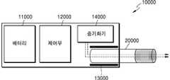
- an aerosol generating apparatus 10000includes a battery 11000, a control unit 12000, a heater 13000, and a vaporizer 14000.
- the cigarette 20000can be inserted into the internal space of the aerosol generating apparatus 10000.
- the apparatus 1300includes the heater 13000, but the heater 13000 may be omitted if necessary.
- a battery 11000, a control unit 12000, a vaporizer 14000, and a heater 13000are arranged in a line. Also shown in Figure 2 is a vaporizer 14000 and a heater 13000 arranged in parallel.
- the internal structure of the aerosol generating apparatus 10000is not limited to that shown in Fig. 1 or Fig. In other words, according to the design of the aerosol generating apparatus 10000, the arrangement of the battery 11000, the control unit 12000, the vaporizer 14000, and the heater 13000 can be changed.
- the aerosol generating apparatus 10000can operate the vaporizer 14000 to generate an aerosol from the vaporizer 14000.
- the aerosol generated by the vaporizer 14000passes through the cigarette 20000 and is delivered to the user.
- the description of the vaporizer 14000will be described later in more detail.
- the battery 11000supplies power used for the aerosol generating apparatus 10000 to operate.
- the battery 11000can supply power so that the heater 13000 or the vaporizer 14000 can be heated, and can supply the power required for the controller 12000 to operate.
- the battery 11000can supply power required for operation of a display, a sensor, a motor, and the like installed in the aerosol generating apparatus 10000.
- the control unit 12000controls the operation of the aerosol generating apparatus 10000 as a whole. Specifically, the control unit 12000 controls the operation of not only the battery 11000, the heater 13000, and the vaporizer 14000, but also other components included in the aerosol generating apparatus 10000. The controller 12000 may also check the status of each of the configurations of the aerosol generator 10000 to determine whether the aerosol generator 10000 is in an operable state.
- the control unit 12000includes at least one processor.
- a processormay be implemented as an array of a plurality of logic gates, or may be implemented as a combination of a general purpose microprocessor and a memory in which a program executable in the microprocessor is stored. It will be appreciated by those skilled in the art that the present invention may be implemented in other forms of hardware.
- the heater 13000can be heated by the power supplied from the battery 11000. [ For example, when the cigarette is inserted into the aerosol generating apparatus 10000, the heater 13000 may be located outside the cigarette. Thus, the heated heater 13000 can raise the temperature of the aerosol generating material in the cigarette.
- the heater 13000may be an electrically resistive heater.
- the heater 13000includes an electrically conductive track, and the heater 13000 can be heated as current flows through the electrically conductive track.
- the heater 13000is not limited to the above-described example, and may be applied without limitation as long as it can be heated to a desired temperature.
- the desired temperaturemay be preset in the aerosol generating apparatus 10000, or may be set to a desired temperature by the user.
- the heater 13000may be an induction heating type heater.
- the heater 13000may include an electrically conductive coil for heating the cigarette by an induction heating method, and the cigarette may include a susceptor that can be heated by an induction heating heater.
- the heater 13000is disposed outside the cigarette 20000, but the present invention is not limited thereto.
- the heater 13000may include a tubular heating element, a plate-like heating element, a sinking heating element, or a rod-shaped heating element, and may be disposed inside or outside the cigarette 20000 It can be heated.
- a plurality of heaters 13000may be disposed in the aerosol generating apparatus 10000. At this time, the plurality of heaters 13000 may be disposed inside the cigarette 20000, or may be disposed outside the cigarette 20000. In addition, some of the plurality of heaters 13000 may be arranged to be inserted into the cigarette 20000, and the rest may be disposed outside the cigarette 20000. Further, the shape of the heater 13000 is not limited to the shapes shown in Figs. 1 and 2, and can be formed into various shapes.
- the vaporizer 14000can heat the liquid composition to produce an aerosol, and the generated aerosol can be passed through the cigarette 20000 to the user.
- the aerosol generated by the vaporizer 14000can move along the airflow passageway of the aerosol generating apparatus 10000, and the airflow passageway allows the aerosol generated by the vaporizer 14000 to pass through the cigarette to the user Lt; / RTI >
- the vaporizer 14000may include, but is not limited to, a liquid reservoir, a liquid delivery means, and a heating element.
- the liquid reservoir, the liquid delivery means, and the heating elementmay be included in the aerosol generation apparatus 10000 as an independent module.
- the liquid reservoircan store the liquid composition.
- the liquid compositionmay be a liquid comprising a tobacco-containing material comprising a volatile tobacco flavor component, or may be a liquid comprising a non-tobacco substance.
- the liquid reservoirmay be fabricated to be removable from the vaporizer 14000 or may be fabricated integrally with the vaporizer 14000.
- the liquid compositionmay comprise water, solvent, ethanol, plant extract, flavoring, flavoring, or a mixture of vitamins.
- the fragrancemay include, but is not limited to, menthol, peppermint, spearmint oil, various fruit flavors, and the like.
- Flavoring agentsmay include ingredients that can provide a variety of flavors or flavors to the user.
- the vitamin mixturemay be a mixture of at least one of vitamin A, vitamin B, vitamin C and vitamin E, but is not limited thereto.
- the liquid compositionmay comprise an aerosol forming agent such as glycerin and propylene glycol.
- the liquid delivery meansmay deliver the liquid composition of the liquid reservoir to the heating element.
- the liquid delivery meanscan be, but is not limited to, wick such as cotton fibers, ceramic fibers, glass fibers, porous ceramics.
- the heating elementis an element for heating the liquid composition delivered by the liquid delivery means.
- the heating elementmay be, but is not limited to, metallic hot wire, metal hot plate, ceramic heater, and the like.
- the heating elementmay be composed of a conductive filament, such as a nichrome wire, and may be disposed in a structure wound on the liquid transfer means. The heating element can be heated by current supply and can transfer heat to the liquid composition in contact with the heating element to heat the liquid composition. As a result, aerosols can be generated.
- vaporizer 14000may be referred to as, but not limited to, a cartomizer or an atomizer.
- the aerosol generating apparatus 10000may further include general configurations other than the battery 11000, the controller 12000, and the heater 13000.
- the aerosol generating apparatus 10000may include a motor for outputting display and / or haptic information capable of outputting visual information.
- the aerosol generating apparatus 10000may include at least one sensor (a puff detection sensor, a temperature detection sensor, a cigarette insertion detection sensor, and the like).
- the aerosol generating apparatus 10000can be constructed in such a structure that external air can flow into the cigarette 20000 even when the cigarette 20000 is inserted, or the internal gas can flow out.
- the aerosol generating apparatus 10000may form a system together with a separate cradle.
- the cradlemay be used to charge the battery 11000 of the aerosol generating apparatus 10000.
- the heater 13000may be heated while the cradle and the aerosol generating apparatus 10000 are coupled.
- the cigarette 20000may be similar to a general soft cigarette.
- the cigarette 20000can be divided into a first portion including an aerosol generating material and a second portion including a filter and the like.
- the second portion of the cigarette 20000may also contain an aerosol generating material.
- an aerosol product made in the form of granules or capsulesmay be inserted into the second part.
- the entire first portionmay be inserted into the interior of the aerosol generating apparatus 10000 and the second portion may be exposed to the outside.
- only a part of the first partmay be inserted into the inside of the aerosol generating apparatus 10000, and a part of the first part and the second part may be inserted.
- the usercan inhale the aerosol from the mouth portion of the second portion. At this time, the aerosol is generated by passing the outside air through the first portion, and the generated aerosol passes through the second portion to the user's mouth.
- the outside airmay be introduced through at least one air passage formed in the aerosol generating apparatus 10000.
- the opening and closing of the air passage formed in the aerosol generating apparatus 10000 and / or the size of the air passagemay be controlled by the user. Accordingly, the amount of smoke, the sense of smell, and the like can be controlled by the user.
- the outside airmay be introduced into the interior of the cigarette 20000 through at least one hole formed in the surface of the cigarette 20000.
- FIG. 3is a view showing an example of a cigarette.
- the cigarette 20000includes a cigarette rod 21000 and a filter rod 22000.
- the first portion described above with reference to Figures 1 and 2includes a tobacco rod 21000 and the second portion includes a filter rod 22000.
- filter rod 22000is shown in Fig. 3 as a single segment, it is not limited thereto.
- the filter load 22000may be composed of a plurality of segments.
- the filter rod 22000may include a first segment that cools the aerosol and a second segment that filters certain components contained in the aerosol.
- the filter rod 22000may further include at least one segment that performs other functions.
- the cigarette 20000may be packaged by at least one wrapper 24000.
- the wrapper 24000may be formed with at least one hole through which the outside air flows or the inside gas flows out.
- the cigarette 20000may be packaged by one wrapper 24000.
- the cigarette 20000may be overlaid by two or more wrappers 24000.
- the tobacco rod 21000may be packaged by a first wrapper, and the filter rod 22000 may be packaged by a second wrapper. Then, the tobacco rod 21000 and the filter rod 22000 packaged by individual wrappers are combined, and the entire cigarette 20000 can be repackaged by the third wrapper.
- each segmentcan be packaged by a separate wrapper.
- the entire cigarette 20000 to which the segments wrapped by the individual wrappers are coupledcan be repackaged by another wrapper.
- the tobacco rod 21000includes an aerosol generating material.
- the aerosol producing materialmay include, but is not limited to, at least one of glycerin, propylene glycol, ethylene glycol, dipropylene glycol, diethylene glycol, triethylene glycol, tetraethylene glycol and oleyl alcohol.
- the tobacco rod 21000may contain other additives such as flavorings, wetting agents and / or organic acids.
- the tobacco rod 21000can be added to the tobacco rod 21000 by spraying a tobacco rod 21000 with a remover such as menthol or a moisturizer.
- the tobacco rod 21000can be manufactured in various ways.
- the tobacco rod 21000may be made of a sheet or a strand.
- the tobacco rod 21000may be made of each chopped tobacco sheet.
- the tobacco rod 21000may be surrounded by a thermal conductive material.
- the thermal conductive materialmay be, but is not limited to, a metal foil such as an aluminum foil.
- the thermally conductive material surrounding the tobacco rod 21000can evenly disperse the heat transferred to the tobacco rod 21000 to improve the thermal conductivity applied to the tobacco rod, thereby improving the taste of the cigarette .
- the heat conducting material surrounding the tobacco rod 21000may serve as a susceptor heated by the induction heating heater. At this time, although not shown in the drawing, the tobacco rod 21000 may further include an additional susceptor in addition to the outer heat conductive material.
- the filter rod 22000may be a cellulose acetate filter.
- the shape of the filter rod 22000is not limited.
- the filter rod 22000may be a cylindrical rod or a tubular rod including a hollow therein.
- the filter rod 22000may also be a recessed type rod. If the filter rod 22000 is composed of a plurality of segments, at least one of the plurality of segments may be fabricated in a different shape.
- the filter rod 22000may be made to produce flavor.
- a reflux liquidmay be injected into the filter rod 22000, and a separate fiber coated with the reflux liquid may be inserted into the interior of the filter rod 22000.
- At least one capsule 23000may be included in the filter rod 22000.
- the capsule 23000may perform a function of generating a flavor or may function to generate an aerosol.
- the capsule 23000may be a structure in which a content liquid containing a perfume is wrapped in a film.
- the capsule 23000may have a spherical or cylindrical shape, but is not limited thereto.
- the cooling segmentmay be made of a polymeric material or a biodegradable polymeric material.
- the cooling segmentmay be made of pure polylactic acid alone, but is not limited thereto.
- the cooling segmentmay be made of a cellulose acetate filter having a plurality of holes.
- the cooling segmentis not limited to the above-described example, and can be applied without restriction if it can perform the function of cooling the aerosol.
- the cigarette 20000may further include a front end filter.
- the pre-stage filteris located on the side of the tobacco rod 21000 opposite to the filter rod 22000.
- the shear filtercan prevent the tobacco rod 21000 from escaping to the outside and prevent the aerosol liquefied from the tobacco rod 21000 from flowing into the aerosol generating device (10000 in Figs. 1 and 2) during smoking have.
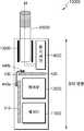
- FIG. 4is a diagram illustrating an example of an aerosol generating device including a rigid PCB and a flexible PCB according to one embodiment.
- the aerosol generating apparatus 10000may include a plurality of PCBs.
- the aerosol generating apparatus 10000may include a main PCB 410 and an auxiliary PCB 420 and a connecting PCB 430 electrically connecting the main PCB 410 and the auxiliary PCB 420 .
- the main PCB 410is disposed parallel to the longitudinal direction of the aerosol generating apparatus 10000, and the auxiliary PCB 420 is disposed perpendicular to the longitudinal direction of the aerosol generating apparatus 10000 have.
- the main PCB 410is disposed parallel to the longitudinal direction of the aerosol generating apparatus 10000 at one side of the battery 11000 and the auxiliary PCB 420 is connected to the heater 13000 14000) and the battery 11000 so as to be perpendicular to the longitudinal direction of the aerosol generating apparatus 10000.
- the battery 11000 and the control unit 12000are arranged in parallel to the longitudinal direction of the aerosol generating apparatus 10000 and the main PCB 410 may be disposed on one side of the battery 11000 and the control unit 12000 have. At this time, the main PCB 410 may be disposed parallel to the longitudinal direction of the aerosol generation apparatus 10000 over at least a portion of the battery 11000 and the control unit 12000.
- the heater 13000 and the vaporizer 14000are disposed in parallel to the longitudinal direction of the aerosol generating apparatus 10000 and the auxiliary PCB 420 is disposed on at least one side of the heater 13000 and the vaporizer 14000. [ Can be disposed.
- the auxiliary PCB 420may be disposed parallel to the longitudinal direction of the aerosol generating apparatus 10000 over at least a portion of the heater 13000 and the vaporizer 14000 and the auxiliary PCB 420 may be disposed in parallel with the heater 13000) and a vaporizer (14000) and a controller (12000).
- connection PCB 430forms a bend and contacts a portion of the main PCB 410 and a portion of the auxiliary PCB 420 to electrically connect the main PCB 410 and the auxiliary PCB 420.
- the connection PCB 430may contact a portion of the top or bottom surface of the main PCB 410 and the auxiliary PCB 420.
- the connecting PCB 430is connected to the main PCB
- the main PCB 410 and the auxiliary PCB 420can be electrically connected to each other by contacting the terminal end portion of the main PCB 410 and the end portion of the auxiliary PCB 420 adjacent to the suction end end portion of the main PCB 410 have.
- the inlet end sidemeans the direction in which the cigarette 2000 is inserted in the aerosol generating apparatus 10000.
- the structure in which the main PCB 410, the auxiliary PCB 420, and the connection PCB 430 are disposed in the aerosol generating apparatus 10000is not limited thereto.
- the main PCB 410 and the auxiliary PCB 420may be constructed of a rigid material.
- the rigid material constituting the main PCB 410 and the auxiliary PCB 420may be any one of FR-1 (Flame Retardant-1), FR-2 (Flame Retardant-2), FR- Retardant-3, FR-4, Flame Retardant-4, CEM-1 and CEM-3.
- FR-1Freme Retardant-1
- FR-2Flume Retardant-2
- FR- Retardant-3FR-4
- Flame Retardant-4Flame Retardant-4
- CEM-1 and CEM-3CEM-1 and CEM-3.
- the main PCB 410 and the auxiliary PCB 420may include an insulating layer and a conductive layer, and may be a build-up type PCB in which an insulating layer and a conductive layer are alternately stacked.
- the main PCB 410 and the auxiliary PCB 420may be six-layer PCBs.
- connection PCB 430may be constructed of a flexible material.
- the flexible material constituting the connection PCB 430may be polyimide. Since the connection PCB 430 is disposed adjacent to the heater 13000 and / or the vaporizer 14000, the temperature of the connection PCB 430 may rise to a high temperature during operation of the aerosol generation apparatus 10000. Since the polyimide can withstand 400 DEG C, the reliability of the connection PCB 430 can be prevented by applying polyimide as a material of the PCB 430. In addition, the manufacturing cost of the PCB can be reduced, and the assembling performance can be improved.
- the connection PCB 430may include a first insulation layer, a conductive layer formed on the first insulation layer, and a second insulation layer laminated on the conductive layer.
- the conductive layercomprises copper
- the first and second insulating layersmay include, but are not limited to, polyimide.
- the connection PCB 430includes a connection area for connecting the main PCB 410 and the auxiliary PCB 420.
- the connection areamay include a plated layer plated on the exposed conductive layer by peeling off the second insulation layer have.
- the copper conductive layermay be exposed by peeling off a portion of the second insulating layer formed of polyimide, and the exposed copper conductive layer may be plated with gold to form a connection area of the connection PCB 430 .
- connection PCB 410 and the auxiliary PCB 420may be electrically connected to the connection PCB 430 through the plating layer in the connection area.
- connection areai.e., the plated layer
- connection PCB 430may be located at both ends of the connection PCB 430. [ Both ends of the connection PCB 430 may be in contact with the main PCB 410 and the auxiliary PCB 420 to electrically connect the main PCB 410 and the auxiliary PCB 420 to each other.
- connection PCB 430It is possible to increase the heat capacity of the connection PCB 430 by plating the exposed copper layer at both ends of the connection PCB 430 with gold so that the connection PCB 430 can be heated by the heater 13000 and / It is possible to prevent overheating due to heat.
- the auxiliary PCB 420is disposed adjacent to the heater 13000 and / or the vaporizer 14000 so that during operation of the aerosol generating apparatus 10000 the temperature of the auxiliary PCB 420 rises to a high temperature . At this time, it is possible to prevent the auxiliary PCB 420 from being overheated by attaching a heat sink to the auxiliary PCB 420 or using the auxiliary PCB 420 having a heat dissipating function.
- Heat-dissipating materialsmay include silicon, rubber, and gel.
- a single PCBmay extend from one end to the other end along the longitudinal direction of the aerosol generating apparatus 10000.
- the aerosol generating apparatus 10000may be constructed by separating PCBs from the main PCB 410 and the auxiliary PCB 420, instead of using a single PCB alone to construct a circuit of the aerosol generating apparatus 10000, The entire size of the aerosol generating apparatus 10000 can be downsized by utilizing the inner space of the aerosol generating apparatus 10000 more efficiently.
- the auxiliary PCB 420may be implemented as a flexible PCB that includes a material such as, for example, a polyimide material.
- the auxiliary PCBs 420are manufactured using materials different from those of the main PCB 410 and are disposed at positions spaced apart from each other independently of each other so that manufacturing cost can be reduced as compared with a case where one PCB is manufactured using a hard material And assembly performance can be improved.
- FIG. 5is a block diagram illustrating components coupled to an auxiliary PCB according to one embodiment.
- the auxiliary PCB 500may be electrically connected to the battery 510, the control unit 520, the pressure reduction sensor 530, the vaporizer 540, and the heater 550. However, this is only an example, and the auxiliary PCB 500 may be electrically connected to other components other than the components 510 to 550 shown in Fig. 5, or a part of the components 510 to 550 shown in Fig. 5 May be omitted.
- the auxiliary PCB 500may be electrically connected to the battery 510 and the control unit 520.
- the control unit 520may be mounted on the auxiliary PCB 500 and electrically connected to the auxiliary PCB 500, for example.
- the battery 510provides power for the components of the aerosol generating apparatus to operate, and the controller 520 is hardware that controls the overall operation of the aerosol generating apparatus.
- the decompression sensor 530is a sensor for sensing the suction pressure when the cigarette inserted into the aerosol generating device is sucked.
- the decompression sensor 530detects the suction pressure of the cigarette inserted into the aerosol generating device from the outside It senses the suction pressure, which is the pressure of air, and generates a signal.
- the decompression sensor 530may be located in the air flow path through which the air introduced from the outside by the user's suction operation (puff operation) of the cigarette moves.
- the auxiliary PCB 500may be electrically connected to the reduced pressure sensor 530.
- the vaporizer 540may include, but is not limited to, a liquid reservoir, a liquid delivery means, and a heating element.
- the liquid composition stored in the liquid reservoirmay be a liquid comprising a tobacco-containing material and / or a non-tobacco material.
- the liquid delivery meanscan deliver the liquid composition of the liquid reservoir to the heating element as a wick, such as a porous ceramic.
- the heating elementis an element for heating the liquid composition delivered by the liquid delivery means.
- the auxiliary PCB 500may be electrically connected to the vaporizer 540.
- the heater 550may heat the aerosol generating material contained in the cigarette.
- the heater 550may be located outside or inside the cigarette.
- the heater 550can include a tubular heating element, a plate-like heating element, a sinking heating element, or a rod-shaped heating element, and can heat the inside or outside of the cigarette according to the shape of the heating element have.
- the auxiliary PCB 500may be electrically connected to the heater 550.
- FIG. 6is a block diagram illustrating components coupled to a main PCB according to one embodiment.
- the main PCB 600may be electrically connected to the battery 610, the controller 620, the temperature sensor 630, the antenna 640, and the interface 650.
- the control unit 620may be attached to the main PCB 600 and electrically connected to the main PCB 600, for example.
- the temperature sensor 630can sense the temperature of the heater that heats the cigarette. In one embodiment, the temperature sensing of the heater may be accomplished by measuring the resistance value of the temperature sensor 630.
- the temperature sensor 630may be located on the side wall or the bottom wall of the receiving passage in which the cigarette is received. However, the temperature sensing method and the position of the temperature sensor 630 are not limited thereto.
- the main PCB 600may be electrically connected to the temperature sensor 630.
- the antenna 640can perform communication with the outside.
- the antenna 640may be a Bluetooth ⁇ antenna capable of performing wireless communication.
- the main PCB 600may be electrically connected to the antenna 640.
- the interface 650may include a display or lamp for outputting visual information, a motor for outputting tactile information, and a speaker for outputting sound information.
- the main PCB 600may be electrically connected to the interface 650.
- FIG. 7is a view showing an example of an aerosol generating apparatus including a rigid-flexible PCB according to an embodiment.
- the aerosol generating apparatus 10000may include a rigid-flexible PCB 720.
- the rigid PCB 720is a single PCB.
- the rigid PCB 720may be made of a first hard portion 711a, a second hard portion 711b, and a soft portion 712.
- the first hard portion 711ais disposed parallel to the longitudinal direction of the aerosol generating apparatus 10000 and the second hard portion 711b is disposed perpendicular to the longitudinal direction of the aerosol generating apparatus 10000,
- the first hard portion 712has a curvature and connects the first hard portion 711a and the second hard portion 711b.
- the first hard portion 711ais disposed parallel to the longitudinal direction of the aerosol generating apparatus 10000 on one side of the battery 11000 and the second hard portion 711b is disposed on the side of the heater 13000 The vaporizer 14000) and the battery 11000 in the direction perpendicular to the longitudinal direction of the aerosol generating apparatus 10000.
- the battery 11000 and the control unit 12000are arranged in parallel to the longitudinal direction of the aerosol generating apparatus 10000 and the first hard portion 711a is disposed on one side of the battery 11000 and the control unit 12000 .
- the first hard portion 711amay be disposed parallel to the longitudinal direction of the aerosol generating apparatus 10000 over at least a portion of the battery 11000 and the control unit 12000.
- the heater 13000 and the vaporizer 14000are arranged in parallel to the longitudinal direction of the aerosol generating apparatus 10000 and at least one side of the heater 13000 and the vaporizer 14000 is provided with a second hard portion 711b may be disposed.
- the second hard portion 711bmay be disposed parallel to the longitudinal direction of the aerosol generation apparatus 10000 over at least a portion of the heater 13000 and the vaporizer 14000 and the second hard portion 711b May be disposed between the heater 13000 and the vaporizer 14000 and the controller 12000.
- the hard material composing the first hard portion 711a and the second hard portion 711bis FR-1 (Flame Retardant-1), FR-2 (Flame Retardant-2) Flame Retardant-3, FR-4, Flame Retardant-4, Composite Epoxy Material-1 and CEM-3 Composite Epoxy Material-3.
- FR-1Flume Retardant-1
- FR-2Flume Retardant-2
- Flame Retardant-3Flame Retardant-3
- FR-4Flame Retardant-4
- Composite Epoxy Material-1 and CEM-3 Composite Epoxy Material-3Composite Epoxy Material-3
- the soft material constituting the soft portion 712may be polyimide. Since the soft portion 712 is disposed adjacent to the heater 13000 and / or the vaporizer 14000, the temperature of the soft portion 712 can rise to a high temperature during operation of the aerosol generating apparatus 10000. Since the polyimide can withstand 400 DEG C, the reliability can be prevented by applying polyimide as the material of the soft portion 712. [ In addition, the manufacturing cost of the PCB can be reduced, and the assembling performance can be improved.
- the second hard portion 711bis disposed adjacent to the heater 13000 and / or the vaporizer 14000, the temperature of the second hard portion 711b during operation of the aerosol generation apparatus 10000 is maintained at a high temperature Can rise. At this time, it is possible to prevent the second hard portion 711b from being overheated by attaching the heat sink to the second hard portion 711b.
- Heat-dissipating materialsmay include silicon, rubber, and gel.
- the first hard portion 711amay be electrically connected to the battery 11000, the control unit 12000, the pressure reduction sensor (not shown), the vaporizer 14000, and the heater 13000.
- the second hard portion 711bmay be electrically connected to a battery 11000, a controller 12000, a temperature sensor (not shown), an antenna (not shown), and an interface (not shown).
- the overall size of the aerosol generating apparatus 10000can be miniaturized by more efficiently utilizing the internal space of the aerosol generating apparatus 10000 by configuring the circuits of the aerosol generating apparatus 10000 by using the hardened PCB 720.
- FIG. 8is a block diagram showing the hardware configuration of the aerosol generating apparatus.
- an aerosol generating apparatus 800may include a controller 810, a heater 820, a battery 830, a memory 840, a sensor 850, and an interface 860.
- the heater 820is electrically heated by the power supplied from the battery 830 under the control of the controller 810. [ When the cigarette moves along the receiving passage and the end of the cigarette reaches the bottom wall of the receiving portion, the heater 820 is located inside or outside the cigarette. Thus, the heated heater 820 can raise the temperature of the aerosol product in the cigarette.
- the heater 820may be inserted into the interior of the cigarette or may be of any type as long as it can heat the exterior of the cigarette. Further, only a part of the heater 820 may be heated.
- the heater 820may be an electrically resistive heater.
- the heater 820includes an electrically conductive track, and the heater 820 can be heated as current flows through the electrically conductive track.
- the heater 820may be supplied with power according to the specifications of 3.2 V, 2.4 A, 8 W, but is not limited thereto.
- the surface temperature of the heater 820may rise to 400 ° C or higher.
- the surface temperature of the heater 820may rise to about 350 ⁇ ⁇ before 15 seconds have elapsed since the power supply to the heater 820 started.
- a separate temperature sensormay be provided around the heater 820 of the aerosol generating apparatus.
- a temperature sensormay not be provided around the heater 820, and the heater 820 may serve as a temperature sensor.
- the heater 820may function as a temperature sensor, and a separate temperature sensor may be further provided around the heater 820.
- the heater 820may include at least one electrically conductive track for heating and temperature sensing.
- the heater 820may further include a second electrically conductive track for sensing temperature in addition to the first electrically conductive track for generating heat.
- the resistance Rcan be determined.
- the temperature (T) of the second electrically conductive trackcan be determined by the following equation (1).
- Rdenotes a current resistance value of the second electrically conductive track
- R0denotes a resistance value at a temperature T0 (for example, 0 ⁇ ⁇ ),? Quot
- the conductive materiale.g., metal
- the conductive materialhas a resistive temperature coefficient inherent thereto, so that? Can be predetermined according to the conductive material constituting the second electrically conductive track.
- the heater 820may be comprised of at least one electrically conductive track (a first electrically conductive track and a second electrically conductive track).
- the heater 820may be composed of two first electrically conductive tracks and one or two second electrically conductive tracks, but is not limited thereto.
- the electrically conductive trackincludes an electrically resistive material.
- the electrically conductive trackcan be made of a metallic material.
- an electrically conductive trackcan be made of an electrically conductive ceramic material, a carbon, a metal alloy, or a composite of a ceramic material and a metal.
- the heater 820may include an electric conductive track and a temperature sensing sensor which serve as a temperature sensing sensor.
- the control unit 810is hardware for controlling the overall operation of the aerosol generating apparatus 800.
- the control unit 810is an integrated circuit implemented with a processing unit such as a microprocessor, a microcontroller, or the like.
- the control unit 810analyzes the results sensed by the sensor 850 and controls the processes to be performed subsequently.
- the control unit 810can start or stop the supply of electric power from the battery 830 to the heater 820 in accordance with the sensing result.
- the controller 810can control the amount of power supplied to the heater 820 and the time at which the power is supplied so that the heater 820 can be heated to a predetermined temperature or maintain a proper temperature.
- the control unit 810can process various input information and output information of the interface 860.
- the control unit 810may count the number of times the user uses the aerosol generating apparatus 800 and control related functions of the aerosol generating apparatus 800 to limit the user's smoking according to the counting result.
- the memory 840is hardware for storing various data processed in the aerosol generating apparatus 800, and the memory 840 can store data processed by the controller 810 and data to be processed.
- the memory 840may be a variety of memory devices such as random access memory (RAM), read-only memory (EEPROM), electrically erasable programmable read-only memory (EEPROM) such as dynamic random access memory (DRAM) And the like.
- the memory 840may store data on a user's smoking pattern such as a smoking time, the number of times of smoking, and the like.
- the memory 840may also store reference temperature change value data when the cigarette is accommodated in the accommodation passage.
- the battery 830supplies the power used to operate the aerosol generating device 800. That is, the battery 830 can supply electric power so that the heater 820 can be heated. The battery 830 can also supply the power required for the operation of the other hardware, the control unit 810, the sensor 850, and the interface 860 provided in the aerosol generation apparatus 800.
- the battery 830may be a lithium phosphate (LiFePO4) battery, but not limited thereto, a lithium cobalt (LiCoO2) battery, a lithium titanate battery, or the like.
- the battery 830may be a rechargeable battery or a disposable battery.
- the sensor 850may include various types of sensors such as a puff detect sensor (a temperature sensor, a flow sensor, a position sensor, etc.), a cigarette insertion sensor, a temperature sensor of the heater 820, .
- the result of sensing by the sensor 850is transmitted to the control unit 810.
- the control unit 810controls various functions such as control of the heater temperature, restriction of smoking, presence / absence of cigarette insertion, To control the aerosol generating device 800 to be performed.
- the interface 860includes a display or lamp for outputting visual information, a motor for outputting tactile information, a speaker for outputting sound information, an input / output (I / O) unit for receiving information input from a user or outputting information to a user, WI-FI, WI-FI Direct, Bluetooth, NFC (for example, WI-FI, WI-FI, etc.) for data communication or receiving charging power with interfacing means Near-Field Communication), and the like).
- the aerosol generating device 800may be implemented by selecting only some of the various interfacing means illustrated above.
Landscapes
- Engineering & Computer Science (AREA)
- Physics & Mathematics (AREA)
- Microelectronics & Electronic Packaging (AREA)
- Chemical Kinetics & Catalysis (AREA)
- General Chemical & Material Sciences (AREA)
- Chemical & Material Sciences (AREA)
- Health & Medical Sciences (AREA)
- General Engineering & Computer Science (AREA)
- Optics & Photonics (AREA)
- General Physics & Mathematics (AREA)
- Electromagnetism (AREA)
- General Health & Medical Sciences (AREA)
- Life Sciences & Earth Sciences (AREA)
- Biomedical Technology (AREA)
- Toxicology (AREA)
- Hematology (AREA)
- Animal Behavior & Ethology (AREA)
- Public Health (AREA)
- Veterinary Medicine (AREA)
- Botany (AREA)
- Heart & Thoracic Surgery (AREA)
- Anesthesiology (AREA)
- Pulmonology (AREA)
- Bioinformatics & Cheminformatics (AREA)
- Agronomy & Crop Science (AREA)
- Resistance Heating (AREA)
- Human Computer Interaction (AREA)
- Computer Networks & Wireless Communication (AREA)
- Containers And Packaging Bodies Having A Special Means To Remove Contents (AREA)
Abstract
Description
Translated fromKorean본 개시는 에어로졸 생성 장치를 제공한다.The present disclosure provides an aerosol generating device.
근래에 일반적인 궐련의 단점들을 극복하는 대체 방법에 관한 수요가 증가하고 있다. 예를 들어, 궐련을 연소시켜 에어로졸을 생성시키는 방법이 아닌 궐련 내의 에어로졸 발생 물질이 가열됨에 따라 에어로졸이 생성되는 방법에 관한 수요가 증가하고 있다.There is a growing demand for alternative methods to overcome the disadvantages of common cigarettes in recent years. For example, there is an increasing demand for a method in which an aerosol is produced as the aerosol generating material in the cigarette is heated, rather than burning the cigarette to produce an aerosol.
전기를 이용하여 궐련을 가열하는 히터를 구비한 전자담배의 경우, 전자담배 내부에 다수의 구성부품이 포함되는데, 다수의 구성부품을 적절하게 배치하지 않는 경우 전자담배의 전체적인 크기가 커질 수 있다.In the case of an electronic cigarette having a heater for heating a cigarette using electricity, a plurality of constituent parts are contained in the electronic cigarette, and the overall size of the electronic cigarette can be increased if a plurality of constituent parts are not arranged appropriately.
이에 따라, 전자담배를 소형화하여 휴대성을 높이기 위한 연구가 활발히 진행되고 있다.Accordingly, studies have been actively made to miniaturize the electronic cigarette to improve portability.
에어로졸 생성 장치를 제공하는데 있다. 본 실시예에 따른 에어로졸 생성 장치는 경성(rigid) 소재의 PCB(RPCB) 및 연성(flexible) 소재의 PCB(FPCB)를 혼용하거나, 경연성 소재의 PCB(RFPCB)를 이용하여, 에어로졸 생성 장치 내부의 회로를 구성할 수 있다.And an apparatus for generating an aerosol. The aerosol generating apparatus according to the present embodiment can be applied to the aerosol generating apparatus by using a rigid PCB (RPCB) and a flexible PCB (FPCB) or using a hardened PCB (RFPCB) Can be configured.
본 실시예가 이루고자 하는 기술적 과제는 상기된 바와 같은 기술적 과제들로 한정되지 않으며, 이하의 실시예들로부터 또 다른 기술적 과제들이 유추될 수 있다.The technical problem to be solved by this embodiment is not limited to the above-mentioned technical problems, and other technical problems can be deduced from the following embodiments.
적어도 하나의 히터, 배터리 및 제어부를 포함하고, 궐련을 가열함으로써 에어로졸을 생성하는 에어로졸 생성 장치를 개시한다.Disclosed is an apparatus for generating aerosols that includes at least one heater, a battery, and a control unit, and generates an aerosol by heating the cigarette.
본 실시예에 따른 에어로졸 생성 장치는 경성(rigid) 소재로 구성된 메인 PCB 및 보조 PCB와, 연성(flexible) 소재로 구성된 연결 PCB를 포함하며, 연결 PCB는 메인 PCB 및 보조 PCB를 전기적으로 연결할 수 있다. 또한, 본 실시예에 따른 에어로졸 생성 장치는 경연성 PCB(rigid-flexible PCB)를 포함할 수 있다.The aerosol generating apparatus according to the present embodiment includes a main PCB and an auxiliary PCB composed of a rigid material and a connecting PCB composed of a flexible material and the connecting PCB can electrically connect the main PCB and the auxiliary PCB . In addition, the aerosol generating apparatus according to the present embodiment may include a rigid-flexible PCB.
본 발명에 따르면, 경성(rigid) 소재의 PCB(RPCB) 및 연성(flexible) 소재의 PCB(FPCB)를 혼용하거나, 경연성 소재의 PCB(RFPCB)를 이용하여, 에어로졸 생성 장치 내부의 회로를 구성함으로써, 에에로졸 생성 장치를 소형화할 수 있다.According to the present invention, it is possible to construct a circuit inside an aerosol generating apparatus by using a rigid PCB (RPCB) and a flexible PCB (FPCB) or by using a PCB (RFPCB) Whereby the aerosol generating apparatus can be downsized.
도 1 및 도 2는 에어로졸 생성 장치에 궐련이 삽입된 예들을 도시한 도면들이다.1 and 2 are views showing examples in which a cigarette is inserted into an aerosol generating apparatus.
도 3은 궐련의 일 예를 도시한 도면이다.3 is a view showing an example of a cigarette.
도 4는 일 실시예에 따른 경성(rigid) PCB 및 연성(flexible) PCB를 포함하는 에어로졸 생성 장치의 일 예를 도시한 도면이다.4 is a diagram illustrating an example of an aerosol generating device including a rigid PCB and a flexible PCB according to one embodiment.
도 5는 일 실시예에 따른 보조 PCB와 연결된 구성부품을 도시한 블록도이다.5 is a block diagram illustrating components coupled to an auxiliary PCB according to one embodiment.
도 6은 일 실시예에 따른 메인 PCB와 연결된 구성부품을 도시한 블록도이다.6 is a block diagram illustrating components coupled to a main PCB according to one embodiment.
도 7은 일 실시예에 따른 경연성 PCB(rigid-flexible PCB)를 포함하는 에어로졸 생성 장치의 일 예를 도시한 도면이다.7 is a view showing an example of an aerosol generating apparatus including a rigid-flexible PCB according to an embodiment.
도 8은 에어로졸 생성 장치의 하드웨어 구성을 도시한 블록도이다.8 is a block diagram showing the hardware configuration of the aerosol generating apparatus.
상술한 기술적 과제를 달성하기 위한 기술적 수단으로서, 본 개시의 제1 측면은, 에어로졸 생성 물질을 가열하여 에어로졸을 생성하는 적어도 하나의 히터; 상기 적어도 하나의 히터가 가열되도록 전력을 공급하는 배터리; 제어부; 및 경성(rigid) 소재로 구성된 메인 PCB 및 보조 PCB;를 포함하고, 상기 메인 PCB는 상기 에어로졸 생성 장치의 길이 방향에 대해 평행하게 배치되고, 상기 보조 PCB는 상기 에어로졸 생성 장치의 길이 방향에 대해 수직으로 배치되며, 상기 메인 PCB는 및 상기 보조 PCB는, 연성(flexible) 소재로 구성된 연결 PCB에 의해 전기적으로 연결되는 것인,에어로졸 생성 장치를 제공할 수 있다.As a technical means to achieve the above-mentioned technical object, a first aspect of the present disclosure provides a method for producing an aerosol comprising: at least one heater for heating an aerosol producing material to produce an aerosol; A battery for supplying power such that the at least one heater is heated; A control unit; And a main PCB and an auxiliary PCB composed of a rigid material, wherein the main PCB is arranged in parallel with the longitudinal direction of the aerosol generating apparatus, and the auxiliary PCB is perpendicular to the longitudinal direction of the aerosol generating apparatus Wherein the main PCB and the auxiliary PCB are electrically connected by a connection PCB composed of a flexible material.
또한, 상기 메인 PCB는 상기 배터리 및 상기 제어부 중 적어도 어느 하나의 일 측면에서 상기 에어로졸 생성 장치의 길이 방향에 대해 평행하게 배치되고, 상기 보조 PCB는 상기 적어도 하나의 히터와 상기 배터리 사이에서 상기 에어로졸 생성 장치의 길이 방향에 대해 수직으로 배치되는 것인, 에어로졸 생성 장치를 제공할 수 있다.The main PCB is arranged parallel to the longitudinal direction of the aerosol generating apparatus on one side of at least one of the battery and the control unit, And is arranged perpendicular to the longitudinal direction of the device.
또한, 상기 적어도 하나의 히터는, 궐련에 포함된 에어로졸 생성 물질을 가열하는 히터; 및 액상 조성물을 가열하여 에어로졸을 생성하는 증기화기;를 포함하고, 상기 보조 PCB는 상기 궐련용 히터 및 상기 증기화기용 히터와 전기적으로 연결되는 것인, 에어로졸 생성 장치를 제공할 수 있다.The at least one heater may further include: a heater for heating the aerosol generating material contained in the cigarette; And a vaporizer for heating the liquid composition to produce an aerosol, wherein the auxiliary PCB is electrically connected to the cigarette heater and the heater for the vaporizer.
또한, 상기 에어로졸 생성 장치는, 상기 에어로졸 생성 장치에 삽입된 궐련이 흡입될 때의 흡입 압력을 감지하는 감압센서;를 더 포함하고, 상기 보조 PCB는 상기 감압센서와 전기적으로 연결되는 것인, 에어로졸 생성 장치를 제공할 수 있다The aerosol generating apparatus may further include a decompression sensor for sensing a suction pressure when the cigarette inserted into the aerosol generating apparatus is sucked, wherein the auxiliary PCB is electrically connected to the decompression sensor, Generating device can be provided
또한, 상기 메인 PCB는, 상기 적어도 하나의 히터의 온도를 감지하는 온도 센서, 외부와의 무선 통신을 위한 안테나, 상기 에어로졸 생성 장치의 작동 상태를 나타내는 인터페이스 중 적어도 어느 하나와 전기적으로 연결되는 것인, 에어로졸 생성 장치를 제공할 수 있다The main PCB may be electrically connected to at least one of a temperature sensor for sensing the temperature of the at least one heater, an antenna for wireless communication with the outside, and an interface for indicating the operating state of the aerosol generating apparatus. , An aerosol generating device can be provided
또한, 상기 메인 PCB 및 상기 보조 PCB를 구성하는 경성(rigid) 소재는 FR-4(Flame Retardant-4)이며, 상기 연결 PCB를 구성하는 연성(flexible) 소재는 폴리이미드(polyimide)인 것인, 에어로졸 생성 장치를 제공할 수 있다In addition, the rigid material constituting the main PCB and the auxiliary PCB is FR-4 (Flame Retardant-4), and the flexible PCB constituting the connection PCB is polyimide. An aerosol generating device can be provided
또한, 상기 보조 PCB가 상기 적어도 하나의 히터에 의해 과열되지 않도록, 상기 보조 PCB에는 방열판이 부착되는 것인, 에어로졸 생성 장치를 제공할 수 있다Also, a heat sink may be attached to the auxiliary PCB so that the auxiliary PCB is not overheated by the at least one heater.
또한, 상기 연결 PCB는 제1 절연층, 상기 제1 절연층상에 형성된 도전층과 상기 도전층에 적층되는 제2 절연층을 포함하고, 상기 연결 PCB는 상기 메인 PCB 및 상기 보조 PCB와 연결하기 위한 연결 영역을 포함하는데, 상기 연결 영역은 상기 제2 절연층이 박리됨으로써 노출된 상기 도전층 상에 도금된 도금층을 포함하고, 상기 메인 PCB 및 상기 보조 PCB는 상기 도금층을 통해 상기 연결 PCB와 연결되는 것인, 에어로졸 생성 장치를 제공할 수 있다.The connecting PCB may include a first insulating layer, a conductive layer formed on the first insulating layer, and a second insulating layer stacked on the conductive layer. The connecting PCB may include a first insulating layer, Wherein the main PCB and the auxiliary PCB are connected to the connection PCB via the plating layer, wherein the connection area includes a plating layer plated on the conductive layer exposed by peeling off the second insulation layer, Lt; RTI ID = 0.0 > aerosol < / RTI > generation device.
또한, 상기 제1 절연층 및 상기 제2 절연층은 폴리이미드를 포함하고, 상기 도전층은 구리를 포함하고, 상기 도금층은 금을 포함하는 것인, 에어로졸 생성 장치를 제공할 수 있다.In addition, the first insulating layer and the second insulating layer may include polyimide, the conductive layer may include copper, and the plating layer may include gold.
본 개시의 제2 측면은, 에어로졸 생성 물질을 가열하여 에어로졸을 생성하는 적어도 하나의 히터; 상기 적어도 하나의 히터가 가열되도록 전력을 공급하는 배터리; 제어부; 및 경연성 PCB(rigid-flexible PCB); 를 포함하고, 상기 경연성 PCB(rigid-flexible PCB)의 제 1 경성(rigid) 부분은 상기 에어로졸 생성 장치의 길이 방향에 대해 평행하게 배치되고, 제 2 경성(rigid) 부분은 상기 에어로졸 생성 장치의 길이 방향에 대해 수직으로 배치되며, 연성(flexible) 부분은 굴곡을 가지며 상기 제 1 경성(rigid) 부분과 상기 제 2 경성(rigid) 부분을 연결해주는 것인, 에어로졸 생성 장치를 제공할 수 있다.A second aspect of the present disclosure is directed to a fuel cell comprising at least one heater for heating an aerosol product to produce an aerosol; A battery for supplying power such that the at least one heater is heated; A control unit; And rigid-flexible PCBs; Wherein a first rigid portion of the rigid-flexible PCB is disposed parallel to a longitudinal direction of the aerosol generation device, and a second rigid portion is disposed in parallel with the longitudinal direction of the aerosol generation device, And wherein the flexible portion has a curvature and connects the first rigid portion and the second rigid portion with respect to the longitudinal direction.
또한, 상기 경연성 PCB(rigid-flexible PCB)의 상기 제 1 경성(rigid) 부분 및 상기 제 2 경성(rigid) 부분의 소재는 FR4(Flame-Retardant 4)이며, 상기 연성(flexible) 부분의 소재는 폴리이미드(polyimide)인 것인, 에어로졸 생성 장치를 제공할 수 있다.Also, the material of the first rigid portion and the second rigid portion of the rigid-flexible PCB is FR4 (Flame-Retardant 4), and the material of the flexible portion Is a polyimide. ≪ Desc / Clms Page number 7 >
또한, 상기 경연성 PCB가 상기 적어도 하나의 히터에 의해 과열되지 않도록, 상기 경연성 PCB에는 방열판이 부착되는 것인, 에어로졸 생성 장치를 제공할 수 있다.The invention also provides an aerosol generating apparatus wherein a heat sink is attached to the rigid PCB so that the rigid PCB is not overheated by the at least one heater.
실시예들에서 사용되는 용어는 본 발명에서의 기능을 고려하면서 가능한 현재 널리 사용되는 일반적인 용어들을 선택하였으나, 이는 당 분야에 종사하는 기술자의 의도 또는 판례, 새로운 기술의 출현 등에 따라 달라질 수 있다. 또한, 특정한 경우는 출원인이 임의로 선정한 용어도 있으며, 이 경우 해당되는 발명의 설명 부분에서 상세히 그 의미를 기재할 것이다. 따라서 본 발명에서 사용되는 용어는 단순한 용어의 명칭이 아닌, 그 용어가 가지는 의미와 본 발명의 전반에 걸친 내용을 토대로 정의되어야 한다.Although the terms used in the embodiments have been selected in consideration of the functions of the present invention, the present general terms are widely used. However, these may vary depending on the intention or circumstance of a person skilled in the art, the emergence of new technologies and the like. Also, in certain cases, there may be a term selected arbitrarily by the applicant, in which case the meaning thereof will be described in detail in the description of the corresponding invention. Therefore, the term used in the present invention should be defined based on the meaning of the term, not on the name of a simple term, but on the entire contents of the present invention.
명세서 전체에서 어떤 부분이 어떤 구성요소를 "포함"한다고 할 때, 이는 특별히 반대되는 기재가 없는 한 다른 구성요소를 제외하는 것이 아니라 다른 구성요소를 더 포함할 수 있음을 의미한다. 또한, 명세서에 기재된 "…부", "…모듈" 등의 용어는 적어도 하나의 기능이나 동작을 처리하는 단위를 의미하며, 이는 하드웨어 또는 소프트웨어로 구현되거나 하드웨어와 소프트웨어의 결합으로 구현될 수 있다.When an element is referred to as " including " an element throughout the specification, it is to be understood that the element may include other elements as well, without departing from the spirit or scope of the present invention. Also, the terms " part, " " module, " and the like, which are described in the specification, refer to a unit for processing at least one function or operation, which may be implemented by hardware or software or by a combination of hardware and software.
아래에서는 첨부한 도면을 참고하여 본 발명의 실시예에 대하여 본 발명이 속하는 기술 분야에서 통상의 지식을 가진 자가 용이하게 실시할 수 있도록 상세히 설명한다. 그러나 본 발명은 여러 가지 상이한 형태로 구현될 수 있으며 여기에서 설명하는 실시예에 한정되지 않는다.Hereinafter, embodiments of the present invention will be described in detail with reference to the accompanying drawings so that those skilled in the art can easily carry out the present invention. The present invention may, however, be embodied in many different forms and should not be construed as limited to the embodiments set forth herein.
이하에서는 도면을 참조하여 본 발명의 실시예들을 상세히 설명한다.Hereinafter, embodiments of the present invention will be described in detail with reference to the drawings.
도 1 및 도 2는 에어로졸 생성 장치에 궐련이 삽입된 예들을 도시한 도면들이다.1 and 2 are views showing examples in which a cigarette is inserted into an aerosol generating apparatus.
도 1 및 도 2를 참조하면, 에어로졸 생성 장치(10000)는 배터리(11000), 제어부(12000), 히터(13000) 및 증기화기(14000)를 포함한다. 또한, 에어로졸 생성 장치(10000)의 내부 공간에는 궐련(20000)이 삽입될 수 있다.Referring to FIGS. 1 and 2, an
도 1 및 도 2에 도시된 에어로졸 생성 장치(10000)에는 본 실시예와 관련된 구성요소들만이 도시되어 있다. 따라서, 도 1 및 도 2에 도시된 구성요소들 외에 다른 범용적인 구성요소들이 에어로졸 생성 장치(10000)에 더 포함될 수 있음을 본 실시예와 관련된 기술분야에서 통상의 지식을 가진 자라면 이해할 수 있다.Only the components related to the present embodiment are shown in the
또한, 도 1 및 도 2에는 에어로졸 생성 장치(10000)에 히터(13000)가 포함되어 있는 것으로 도시되어 있으나, 필요에 따라, 히터(13000)는 생략될 수도 있다.1 and 2 show that the
도 1에는 배터리(11000), 제어부(12000), 증기화기(14000) 및 히터(13000)가 일렬로 배치된 것으로 도시되어 있다. 또한, 도 2에는 증기화기(14000) 및 히터(13000)가 병렬로 배치된 것으로 도시되어 있다. 그러나, 에어로졸 생성 장치(10000)의 내부 구조는 도 1 또는 도 2에 도시된 것에 한정되지 않는다. 다시 말해, 에어로졸 생성 장치(10000)의 설계에 따라, 배터리(11000), 제어부(12000), 증기화기(14000) 및 히터(13000)의 배치는 변경될 수 있다.1, a
궐련(20000)이 에어로졸 생성 장치(10000)에 삽입되면, 에어로졸 생성 장치(10000)는 증기화기(14000)를 작동시켜, 증기화기(14000)로부터 에어로졸을 발생시킬 수 있다. 증기화기(14000)에 의해 생성된 에어로졸은 궐련(20000)을 통과하여 사용자에게 전달된다. 증기화기(14000)에 관한 설명은 하기에서 보다 상세히 하기로 한다.When the
배터리(11000)는 에어로졸 생성 장치(10000)가 동작하는데 이용되는 전력을 공급한다. 예를 들어, 배터리(11000)는 히터(13000) 또는 증기화기(14000)가 가열될 수 있도록 전력을 공급할 수 있고, 제어부(12000)가 동작하는데 필요한 전력을 공급할 수 있다. 또한, 배터리(11000)는 에어로졸 생성 장치(10000)에 설치된 디스플레이, 센서, 모터 등이 동작하는데 필요한 전력을 공급할 수 있다.The
제어부(12000)는 에어로졸 생성 장치(10000)의 동작을 전반적으로 제어한다. 구체적으로, 제어부(12000)는 배터리(11000), 히터(13000) 및 증기화기(14000)뿐 만 아니라 에어로졸 생성 장치(10000)에 포함된 다른 구성들의 동작을 제어한다. 또한, 제어부(12000)는 에어로졸 생성 장치(10000)의 구성들 각각의 상태를 확인하여, 에어로졸 생성 장치(10000)가 동작 가능한 상태인지 여부를 판단할 수도 있다.The
제어부(12000)는 적어도 하나의 프로세서를 포함한다. 프로세서는 다수의 논리 게이트들의 어레이로 구현될 수도 있고, 범용적인 마이크로 프로세서와 이 마이크로 프로세서에서 실행될 수 있는 프로그램이 저장된 메모리의 조합으로 구현될 수도 있다. 또한, 다른 형태의 하드웨어로 구현될 수도 있음을 본 실시예가 속하는 기술분야에서 통상의 지식을 가진 자라면 이해할 수 있다.The
히터(13000)는 배터리(11000)로부터 공급된 전력에 의하여 가열될 수 있다. 예를 들어, 궐련이 에어로졸 생성 장치(10000)에 삽입되면, 히터(13000)는 궐련의 외부에 위치할 수 있다. 따라서, 가열된 히터(13000)는 궐련 내의 에어로졸 생성 물질의 온도를 상승시킬 수 있다.The
히터(13000)는 전기 저항성 히터일 수 있다. 예를 들어, 히터(13000)에는 전기 전도성 트랙(track)을 포함하고, 전기 전도성 트랙에 전류가 흐름에 따라 히터(13000)가 가열될 수 있다. 그러나, 히터(13000)는 상술한 예에 한정되지 않으며, 희망 온도까지 가열될 수 있는 것이라면 제한 없이 해당될 수 있다. 여기에서, 희망 온도는 에어로졸 생성 장치(10000)에 기 설정되어 있을 수도 있고, 사용자에 의하여 원하는 온도로 설정될 수도 있다.The
한편, 다른 예로, 히터(13000)는 유도 가열식 히터일 수 있다. 구체적으로, 히터(13000)에는 궐련을 유도 가열 방식으로 가열하기 위한 전기 전도성 코일을 포함할 수 있으며, 궐련은 유도 가열식 히터에 의해 가열될 수 있는 서셉터를 포함할 수 있다.On the other hand, as another example, the
도 1 및 도 2에는 히터(13000)가 궐련(20000)의 외부에 배치되는 것으로 도시되어 있으나, 이에 한정되지 않는다. 예를 들어, 히터(13000)는 관 형 가열 요소, 판 형 가열 요소, 침 형 가열 요소 또는 봉 형의 가열 요소를 포함할 수 있으며, 가열 요소의 모양에 따라 궐련(20000)의 내부 또는 외부를 가열할 수 있다.1 and 2, the
또한, 에어로졸 생성 장치(10000)에는 히터(13000)가 복수 개 배치될 수도 있다. 이때, 복수 개의 히터(13000)들은 궐련(20000)의 내부에 삽입되도록 배치될 수도 있고, 궐련(20000)의 외부에 배치될 수도 있다. 또한, 복수 개의 히터(13000)들 중 일부는 궐련(20000)의 내부에 삽입되도록 배치되고, 나머지는 궐련(20000)의 외부에 배치될 수 있다. 또한, 히터(13000)의 형상은 도 1 및 도 2에 도시된 형상에 한정되지 않고, 다양한 형상으로 제작될 수 있다.In addition, a plurality of
증기화기(14000)는 액상 조성물을 가열하여 에어로졸을 생성할 수 있으며, 생성된 에어로졸은 궐련(20000)을 통과하여 사용자에게 전달될 수 있다. 다시 말해, 증기화기(14000)에 의하여 생성된 에어로졸은 에어로졸 생성 장치(10000)의 기류 통로를 따라 이동할 수 있고, 기류 통로는 증기화기(14000)에 의하여 생성된 에어로졸이 궐련을 통과하여 사용자에게 전달될 수 있도록 구성될 수 있다.The
예를 들어, 증기화기(14000)는 액체 저장부, 액체 전달 수단 및 가열 요소를 포함할 수 있으나, 이에 한정되지 않는다. 예를 들어, 액체 저장부, 액체 전달 수단 및 가열 요소는 독립적인 모듈로서 에어로졸 생성 장치(10000)에 포함될 수도 있다.For example, the
액체 저장부는 액상 조성물을 저장할 수 있다. 예를 들어, 액상 조성물은 휘발성 담배 향 성분을 포함하는 담배 함유 물질을 포함하는 액체일 수 있고, 비 담배 물질을 포함하는 액체일 수도 있다. 액체 저장부는 증기화기(14000)로부터 탈/부착될 수 있도록 제작될 수도 있고, 증기화기(14000)와 일체로서 제작될 수도 있다.The liquid reservoir can store the liquid composition. For example, the liquid composition may be a liquid comprising a tobacco-containing material comprising a volatile tobacco flavor component, or may be a liquid comprising a non-tobacco substance. The liquid reservoir may be fabricated to be removable from the
예를 들어, 액상 조성물은 물, 솔벤트, 에탄올, 식물 추출물, 향료, 향미제, 또는 비타민 혼합물을 포함할 수 있다. 향료는 멘솔, 페퍼민트, 스피아민트 오일, 각종 과일향 성분 등을 포함할 수 있으나, 이에 제한되지 않는다. 향미제는 사용자에게 다양한 향미 또는 풍미를 제공할 수 있는 성분을 포함할 수 있다. 비타민 혼합물은 비타민 A, 비타민 B, 비타민 C 및 비타민 E 중 적어도 하나가 혼합된 것일 수 있으나, 이에 제한되지 않는다. 또한, 액상 조성물은 글리세린 및 프로필렌 글리콜과 같은 에어로졸 형성제를 포함할 수 있다.For example, the liquid composition may comprise water, solvent, ethanol, plant extract, flavoring, flavoring, or a mixture of vitamins. The fragrance may include, but is not limited to, menthol, peppermint, spearmint oil, various fruit flavors, and the like. Flavoring agents may include ingredients that can provide a variety of flavors or flavors to the user. The vitamin mixture may be a mixture of at least one of vitamin A, vitamin B, vitamin C and vitamin E, but is not limited thereto. In addition, the liquid composition may comprise an aerosol forming agent such as glycerin and propylene glycol.
액체 전달 수단은 액체 저장부의 액상 조성물을 가열 요소로 전달할 수 있다. 예를 들어, 액체 전달 수단은 면 섬유, 세라믹 섬유, 유리 섬유, 다공성 세라믹과 같은 심지(wick)가 될 수 있으나, 이에 한정되지 않는다.The liquid delivery means may deliver the liquid composition of the liquid reservoir to the heating element. For example, the liquid delivery means can be, but is not limited to, wick such as cotton fibers, ceramic fibers, glass fibers, porous ceramics.
가열 요소는 액체 전달 수단에 의해 전달되는 액상 조성물을 가열하기 위한 요소이다. 예를 들어, 가열 요소는 금속 열선, 금속 열판, 세라믹 히터 등이 될 수 있으나, 이에 한정되지 않는다. 또한, 가열 요소는 니크롬선과 같은 전도성 필라멘트로 구성될 수 있고, 액체 전달 수단에 감기는 구조로 배치될 수 있다. 가열 요소는, 전류 공급에 의해 가열될 수 있으며, 가열 요소와 접촉된 액체 조성물에 열을 전달하여, 액체 조성물을 가열할 수 있다. 그 결과, 에어로졸이 생성될 수 있다.The heating element is an element for heating the liquid composition delivered by the liquid delivery means. For example, the heating element may be, but is not limited to, metallic hot wire, metal hot plate, ceramic heater, and the like. Further, the heating element may be composed of a conductive filament, such as a nichrome wire, and may be disposed in a structure wound on the liquid transfer means. The heating element can be heated by current supply and can transfer heat to the liquid composition in contact with the heating element to heat the liquid composition. As a result, aerosols can be generated.
예를 들어, 증기화기(14000)는 카토마이저(cartomizer) 또는 무화기(atomizer)로 지칭될 수 있으나, 이에 한정되지 않는다.For example,
한편, 에어로졸 생성 장치(10000)는 배터리(11000), 제어부(12000) 및 히터(13000) 외에 범용적인 구성들을 더 포함할 수 있다. 예를 들어, 에어로졸 생성 장치(10000)는 시각 정보의 출력이 가능한 디스플레이 및/또는 촉각 정보의 출력을 위한 모터를 포함할 수 있다. 또한, 에어로졸 생성 장치(10000)는 적어도 하나의 센서(퍼프 감지 센서, 온도 감지 센서, 궐련 삽입 감지 센서 등)를 포함할 수 있다. 또한, 에어로졸 생성 장치(10000)는 궐련(20000)이 삽입된 상태에서도 외부 공기가 유입되거나, 내부 기체가 유출 될 수 있는 구조로 제작될 수 있다.Meanwhile, the
도 1 및 도 2에는 도시되지 않았으나, 에어로졸 생성 장치(10000)는 별도의 크래들과 함께 시스템을 구성할 수도 있다. 예를 들어, 크래들은 에어로졸 생성 장치(10000)의 배터리(11000)의 충전에 이용될 수 있다. 또는, 크래들과 에어로졸 생성 장치(10000)가 결합된 상태에서 히터(13000)가 가열될 수도 있다.Although not shown in FIGS. 1 and 2, the
궐련(20000)은 일반적인 연소형 궐련과 유사할 수 있다. 예를 들어, 궐련(20000)은 에어로졸 생성 물질을 포함하는 제 1 부분과 필터 등을 포함하는 제 2 부분으로 구분될 수 있다. 또는, 궐련(20000)의 제 2 부분에도 에어로졸 생성 물질이 포함될 수도 있다. 예를 들어, 과립 또는 캡슐의 형태로 만들어진 에어로졸 생성 물질이 제 2 부분에 삽입될 수도 있다.The
에어로졸 생성 장치(10000)의 내부에는 제 1 부분 전체가 삽입되고, 제 2 부분은 외부에 노출될 수 있다. 또는, 에어로졸 생성 장치(10000)의 내부에 제 1 부분의 일부만 삽입될 수도 있고, 제 1 부분 및 제 2 부분의 일부가 삽입될 수도 있다. 사용자는 제 2 부분을 입으로 문 상태에서 에어로졸을 흡입할 수 있다. 이때, 에어로졸은 외부 공기가 제 1 부분을 통과함으로써 생성되고, 생성된 에어로졸은 제 2 부분을 통과하여 사용자의 입으로 전달된다.The entire first portion may be inserted into the interior of the
일 예로서, 외부 공기는 에어로졸 생성 장치(10000)에 형성된 적어도 하나의 공기 통로를 통하여 유입될 수 있다. 예를 들어, 에어로졸 생성 장치(10000)에 형성된 공기 통로의 개폐 및/또는 공기 통로의 크기는 사용자에 의하여 조절될 수 있다. 이에 따라, 무화량, 끽연감 등이 사용자에 의하여 조절될 수 있다. 다른 예로서, 외부 공기는 궐련(20000)의 표면에 형성된 적어도 하나의 구멍(hole)을 통하여 궐련(20000)의 내부로 유입될 수도 있다.As an example, the outside air may be introduced through at least one air passage formed in the
이하, 도 3을 참조하여, 궐련(20000)의 일 예에 대하여 설명한다.Hereinafter, an example of the
도 3은 궐련의 일 예를 도시한 도면이다.3 is a view showing an example of a cigarette.
도 3을 참조하면, 궐련(20000)은 담배 로드(21000) 및 필터 로드(22000)를 포함한다. 도 1 및 도 2를 참조하여 상술한 제 1 부분은 담배 로드(21000)를 포함하고, 제 2 부분은 필터 로드(22000)를 포함한다.Referring to Fig. 3, the
도 3에는 필터 로드(22000)가 단일 세그먼트로 도시되어 있으나, 이에 한정되지 않는다. 다시 말해, 필터 로드(22000)는 복수의 세그먼트들로 구성될 수도 있다. 예를 들어, 필터 로드(22000)는 에어로졸을 냉각하는 제 1 세그먼트 및 에어로졸 내에 포함된 소정의 성분을 필터링하는 제 2 세그먼트를 포함할 수 있다. 또한, 필요에 따라, 필터 로드(22000)에는 다른 기능을 수행하는 적어도 하나의 세그먼트를 더 포함할 수 있다.Although
궐련(20000)은 적어도 하나의 래퍼(24000)에 의하여 포장될 수 있다. 래퍼(24000)에는 외부 공기가 유입되거나 내부 기체가 유출되는 적어도 하나의 구멍(hole)이 형성될 수 있다. 일 예로서, 궐련(20000)은 하나의 래퍼(24000)에 의하여 포장될 수 있다. 다른 예로서, 궐련(20000)은 2 이상의 래퍼(24000)들에 의하여 중첩적으로 포장될 수도 있다. 예를 들어, 제 1 래퍼에 의하여 담배 로드(21000)가 포장되고, 제 2 래퍼에 의하여 필터 로드(22000)가 포장될 수 있다. 그리고, 개별 래퍼에 의하여 포장된 담배 로드(21000) 및 필터 로드(22000)가 결합되고, 제 3 래퍼에 의하여 궐련(20000) 전체가 재포장될 수 있다. 만약, 담배 로드(21000) 또는 필터 로드(22000) 각각이 복수의 세그먼트들로 구성되어 있다면, 각각의 세그먼트가 개별 래퍼에 의하여 포장될 수 있다. 그리고, 개별 래퍼에 의하여 포장된 세그먼트들이 결합된 궐련(20000) 전체가 다른 래퍼에 의하여 재포장될 수 있다.The
담배 로드(21000)는 에어로졸 생성 물질을 포함한다. 예를 들어, 에어로졸 생성 물질은 글리세린, 프로필렌 글리콜, 에틸렌 글리콜, 디프로필렌 글리콜, 디에틸렌 글리콜, 트리에틸렌 글리콜, 테트라에틸렌 글리콜 및 올레일 알코올 중 적어도 하나를 포함할 수 있으나, 이에 한정되지 않는다. 또한, 담배 로드(21000)는 풍미제, 습윤제 및/또는 유기산(organic acid)과 같은 다른 첨가 물질을 함유할 수 있다. 또한, 담배 로드(21000)에는, 멘솔 또는 보습제 등의 가향액이, 담배 로드(21000)에 분사됨으로써 첨가할 수 있다.The
담배 로드(21000)는 다양하게 제작될 수 있다. 예를 들어, 담배 로드(21000)는 시트(sheet)로 제작될 수도 있고, 가닥(strand)으로 제작될 수도 있다. 또한, 담배 로드(21000)는 담배 시트가 잘게 잘린 각초로 제작될 수도 있다. 또한, 담배 로드(21000)는 열 전도 물질에 의하여 둘러싸일 수 있다. 예를 들어, 열 전도 물질은 알루미늄 호일과 같은 금속 호일일 수 있으나, 이에 한정되지 않는다. 일 예로, 담배 로드(21000)를 둘러싸는 열 전도 물질은 담배 로드(21000)에 전달되는 열을 고르게 분산시켜 담배 로드에 가해지는 열 전도율을 향상시킬 수 있으며, 이로 인해 담배 맛을 향상시킬 수 있다. 또한, 담배 로드(21000)를 둘러싸는 열 전도 물질은 유도 가열식 히터에 의해 가열되는 서셉터로서의 기능을 할 수 있다. 이때, 도면에 도시되지는 않았으나, 담배 로드(21000)는 외부를 둘러싸는 열 전도 물질 이외에도 추가의 서셉터를 더 포함할 수 있다.The
필터 로드(22000)는 셀룰로오스 아세테이트 필터일 수 있다. 한편, 필터 로드(22000)의 형상에는 제한이 없다. 예를 들어, 필터 로드(22000)는 원기둥 형(type) 로드일 수도 있고, 내부에 중공을 포함하는 튜브 형(type) 로드일 수도 있다. 또한, 필터 로드(22000)는 리세스 형(type) 로드일 수도 있다. 만약, 필터 로드(22000)가 복수의 세그먼트들로 구성된 경우, 복수의 세그먼트들 중 적어도 하나가 다른 형상으로 제작될 수도 있다.The
필터 로드(22000)는 향미가 발생되도록 제작될 수도 있다. 일 예로서, 필터 로드(22000)에 가향액이 분사될 수도 있고, 가향액이 도포된 별도의 섬유가 필터 로드(22000)의 내부에 삽입될 수도 있다.The
또한, 필터 로드(22000)에는 적어도 하나의 캡슐(23000)이 포함될 수 있다. 여기에서, 캡슐(23000)은 향미를 발생시키는 기능을 수행할 수도 있고, 에어로졸을 발생시키는 기능을 수행할 수도 있다. 예를 들어, 캡슐(23000)은 향료를 포함하는 내용액을 피막으로 감싼 구조일 수 있다. 캡슐(23000)은 구형 또는 원통형의 형상을 갖을 수 있으나, 이에 제한되지 않는다.Also, at least one
만약, 필터 로드(22000)에 에어로졸을 냉각하는 세그먼트가 포함될 경우, 냉각 세그먼트는 고분자 물질 또는 생분해성 고분자 물질로 제조될 수 있다. 예를 들어, 냉각 세그먼트는 순수한 폴리락트산 만으로 제작될 수 있으나, 이에 한정되지 않는다. 또는, 냉각 세그먼트는 복수의 구멍들이 뚫린 셀룰로오스 아세테이트 필터로 제작될 수 있다. 그러나, 냉각 세그먼트는 상술한 예에 한정되지 않고, 에어로졸이 냉각되는 기능을 수행할 수 있다면, 제한 없이 해당될 수 있다.If the
한편, 도 3에는 도시되지 않았으나, 일 실시예에 따른 궐련(20000)은 전단 필터를 더 포함할 수 있다. 전단 필터는 담배 로드(21000)에 있어서, 필터 로드(22000)에 대향하는 일측에 위치한다. 전단 필터는 담배 로드(21000)가 외부로 이탈하는 것을 방지할 수 있으며, 흡연 중에 담배 로드(21000)로부터 액상화된 에어로졸이 에어로졸 발생 장치(도 1 및 도 2의 10000)로 흘러 들어가는 것을 방지할 수 있다.Although not shown in FIG. 3, the
도 4는 일 실시예에 따른 경성(rigid) PCB 및 연성(flexible) PCB를 포함하는 에어로졸 생성 장치의 일 예를 도시한 도면이다.4 is a diagram illustrating an example of an aerosol generating device including a rigid PCB and a flexible PCB according to one embodiment.
이하에서는 도 3과 중복되는 내용은 편의상 생략하기로 한다.Hereinafter, the contents overlapping with FIG. 3 will be omitted for convenience.
에어로졸 생성 장치(10000)는 복수의 PCB를 포함할 수 있다. 일 실시예에서 에어로졸 생성 장치(10000)는 메인 PCB(410)와 보조 PCB(420), 그리고 메인 PCB(410)와 보조 PCB(420)를 전기적으로 연결하는 연결 PCB(430)를 포함할 수 있다.The
도 4를 참조하면, 메인 PCB(410)은 에어로졸 생성 장치(10000)의 길이 방향에 대해 평행하게 배치되고, 보조 PCB(420)는 에어로졸 생성 장치(10000)의 길이 방향에 대해 수직으로 배치될 수 있다.4, the
일 실시예에서, 메인 PCB(410)는 배터리(11000)의 일 측면에서 에어로졸 생성 장치(10000)의 길이 방향에 대해 평행하게 배치되고, 보조 PCB(420)는 히터(13000)(또는 증기화기(14000))와 배터리(11000) 사이에서 에어로졸 생성 장치(10000)의 길이 방향에 대해 수직으로 배치될 수 있다.The
또한, 배터리(11000) 및 제어부(12000)는 에어로졸 생성 장치(10000)의 길이 방향에 대해 나란하게 배치되고, 배터리(11000) 및 제어부(12000)의 일 측면에는 메인 PCB(410)가 배치될 수 있다. 이 때, 메인 PCB(410)는 배터리(11000) 및 제어부(12000)의 적어도 일부에 걸쳐 에어로졸 생성 장치(10000)의 길이 방향에 평행하게 배치될 수 있다. 히터(13000) 및 증기화기(14000)는 에어로졸 생성 장치(10000)의 길이 방향의 수직 방향에 대해 나란하게 배치되고, 히터(13000) 및 증기화기(14000)의 적어도 일 측면에는 보조 PCB(420)가 배치될 수 있다. 이 때, 보조 PCB(420)는 히터(13000) 및 증기화기(14000)의 적어도 일부에 걸쳐 에어로졸 생성 장치(10000)의 길이 방향에 대해 평행하게 배치될 수 있으며, 보조 PCB(420)는 히터(13000) 및 증기화기(14000)와 제어부(12000) 사이에 배치될 수 있다.The
연결 PCB(430)는 굴곡을 형성하며 메인 PCB(410)의 일부 영역 및 보조 PCB(420)의 일부 영역과 접촉함으로써, 메인 PCB(410)와 보조 PCB(420)를 전기적으로 연결할 수 있다. 연결 PCB(430)는 메인 PCB(410) 및 보조 PCB(420)의 상면 또는 하면의 일부 영역과 접촉할 수 있다.The
일 실시예에서, 메인 PCB(410)가 배터리(11000) 및 제어부(12000)의 일 측면에서 에어로졸 생성 장치(10000)의 길이 방향에 대해 평행하게 배치된 경우, 연결 PCB(430)는 메인 PCB(410)의 흡구단측 말단 부분, 및 메인 PCB(410)의 흡구단측 말단 부분과 인접한 보조 PCB(420)의 말단 부분에 접촉함으로써 메인 PCB(410)와 보조 PCB(420)를 전기적으로 연결할 수 있다. 한편, 흡구단측이란 에어로졸 생성 장치(10000)에서 궐련(2000)이 삽입되는 방향을 의미한다.In one embodiment, when the
그러나, 에어로졸 생성 장치(10000) 내부에서 메인 PCB(410), 보조 PCB(420) 및 연결 PCB(430)가 배치되는 구조는 이에 제한되지 않는다.However, the structure in which the
일 실시예에서 메인 PCB(410) 및 보조 PCB(420)는 경성(rigid) 소재로 구성될 수 있다. 예를 들어, 메인 PCB(410) 및 보조 PCB(420)를 구성하는 경성(rigid) 소재는, FR-1(Flame Retardant-1), FR-2(Flame Retardant-2), FR-3(Flame Retardant-3), FR-4(Flame Retardant-4), CEM-1(Composite Epoxy Material-1), CEM-3(Composite Epoxy Material-3) 중 어느 하나일 수 있다. 그러나, 이에 제한되지 않는다.In one embodiment, the
메인 PCB(410) 및 보조 PCB(420)는 절연층과 도전층을 포함할 수 있으며, 절연층과 도전층이 교대로 적층된 build-up 방식의 PCB일 수 있다. 예를 들어, 메인 PCB(410) 및 보조 PCB(420)는 6층(layer) PCB일 수 있다.The
일 실시예에서 연결 PCB(430)는 연성(flexible) 소재로 구성될 수 있다. 예를 들어, 연결 PCB(430)를 구성하는 연성(flexible) 소재는 폴리이미드(polyimide)일 수 있다. 연결 PCB(430)는 히터(13000) 및/또는 증기화기(14000)에 인접하여 배치되므로, 에어로졸 생성 장치(10000)의 동작 중에 연결 PCB(430)의 온도는 높은 온도까지 상승할 수 있다. 폴리이미드(polyimide)는 400℃까지 견딜 수 있으므로, 연결 PCB(430)의 소재로 폴리이미드(polyimide)를 적용함으로써 신뢰성 저하를 방지할 수 있다. 또한, PCB 제조 단가를 절감할 수 있으며 조립 성능을 개선할 수 있다.In one embodiment, the
연결 PCB(430)는 제1 절연층, 제1 절연층 상에 형성된 도전층과, 도전층에 적층되는 제2 절연층을 포함할 수 있다. 일 실시예에서 도전층은 구리를 포함하고, 제1 절연층 및 제2 절연층은 폴리이미드를 포함할 수 있으나, 이에 제한되지 않는다.The
연결 PCB(430)는 메인 PCB(410)와 보조 PCB(420)를 연결하기 위한 연결 영역을 포함하는데, 연결 영역은 제2 절연층이 박리됨으로써 노출된 도전층 상에 도금된 도금층을 포함할 수 있다. 예를 들어, 폴리이미드로 형성된 제2 절연층의 일부 영역을 박리시킴으로써 구리 도전층을 노출시킬 수 있고, 노출된 구리 도전층을 금으로 도금함으로써 연결 PCB(430)의 연결 영역을 형성할 수 있다.The
메인 PCB(410)와 보조 PCB(420)는 연결 영역의 도금층을 통해 연결 PCB(430)와 전기적으로 연결될 수 있다. 일 실시예에서 연결 PCB(430)의 연결 영역(즉, 도금층)은 연결 PCB(430)의 양 단부에 위치할 수 있다. 즉, 연결 PCB(430)의 양 단부는 각각 메인 PCB(410) 및 보조 PCB(420)에 접촉하여 메인 PCB(410) 및 보조 PCB(420)를 전기적으로 연결할 수 있다.The
연결 PCB(430)의 양 단부에서 노출된 구리 층을 금으로 도금함으로써 연결 PCB(430)의 열용량을 증가시킬 수 있고, 이로써 연결 PCB(430)가 히터(13000) 및/또는 증기화기(14000)에 의해 과열되는 것을 방지할 수 있다.It is possible to increase the heat capacity of the
일 실시예에서 보조 PCB(420)는 히터(13000) 및/또는 증기화기(14000)에 인접하여 배치되므로, 에어로졸 생성 장치(10000)의 동작 중에 보조 PCB(420)의 온도는 높은 온도까지 상승할 수 있다. 이 때, 보조 PCB(420)에 방열판을 부착하거나, 방열 기능을 갖는 보조 PCB(420)를 이용함으로써 보조 PCB(420)가 과열되는 것을 방지할 수 있다. 방열 역할을 하는 소재에는 실리콘, 고무, 겔이 포함될 수 있다.The
단일 PCB 만을 이용하여 에어로졸 생성 장치(10000)의 회로를 구성하는 경우, 단일 PCB는 에어로졸 생성 장치(10000)의 길이 방향을 따라 한쪽 끝 단에서 다른 한쪽 끝 단까지 연장될 수 있다. 도 4를 참조하면, 단일 PCB만을 이용하여 에어로졸 생성 장치(10000)의 회로를 구성하는 대신, 메인 PCB(410) 및 보조 PCB(420)로 PCB를 분리하여 회로를 구성함으로써 에어로졸 생성 장치(10000)의 내부 공간을 보다 효율적으로 활용하여 에어로졸 생성 장치(10000)의 전체적인 크기를 소형화할 수 있다.When a circuit of the
한편, 다른 실시예에서 보조 PCB(420)는 예를 들어 폴리이미드 소재와 같은 소재를 포함하는 연성 PCB로 구현할 수 있다. 보조 PCB(420)를 메인 PCB(410)와 상이한 소재를 이용하여 제조하여 서로 독립적이게 이격된 위치에 설치함으로써, 경성의 소재를 이용하여 하나의 PCB를 제조하는 경우에 비하여 제조 단가를 절감할 수 있으며 조립 성능이 개선될 수 있다.Meanwhile, in other embodiments, the
도 5는 일 실시예에 따른 보조 PCB와 연결된 구성부품을 도시한 블록도이다.5 is a block diagram illustrating components coupled to an auxiliary PCB according to one embodiment.
도 5를 참조하면, 보조 PCB(500)는 배터리(510), 제어부(520), 감압센서(530), 증기화기(540) 및 히터(550)와 전기적으로 연결될 수 있다. 그러나 이는 예시일 뿐이며, 보조 PCB(500)는 도 5에 도시된 구성부품(510 내지 550) 외에 다른 구성부품과도 전기적으로 연결되거나, 도 5에 도시된 구성부품(510 내지 550) 중 일부가 생략될 수도 있다.5, the
보조 PCB(500)는 배터리(510) 및 제어부(520)와 전기적으로 연결될 수 있다. 제어부(520)는, 예를 들어, 보조 PCB(500) 상에 부착되어 보조 PCB(500)와 전기적으로 연결될 수 있다. 배터리(510)는 에어로졸 생성 장치의 구성부품들이 동작할 수 있도록 전력을 공급하며, 제어부(520)는 에어로졸 생성 장치의 전반적인 동작을 제어하는 하드웨어이다.The
감압센서(530)는 에어로졸 생성 장치에 삽입된 궐련이 흡입될 때의 흡입 압력을 감지하는 센서로서, 감압센서(530)는 사용자가 궐련을 빨아들이는 동작(퍼프 동작)에 의해 외부로부터 유입된 공기의 압력인 흡입압력을 감지하여 신호를 발생시킨다. 일 실시예에서 감압센서(530)는 사용자가 궐련을 빨아들이는 동작(퍼프 동작)에 의해 외부로부터 유입된 공기가 이동하는 기류패스에 위치할 수 있다. 보조 PCB(500)는 감압센서(530)와 전기적으로 연결될 수 있다.The
증기화기(540)는 액체 저장부, 액체 전달 수단 및 가열 요소를 포함할 수 있으나, 이에 제한되지 않는다. 액체 저장부에 저장된 액상 조성물은 담배 함유 물질 및/또는 비담배 물질을 포함하는 액체일 수 있다. 액체 전달 수단은 다공성 세라믹과 같은 심지(wick)로서 액체 저장부의 액상 조성물을 가열 요소로 전달할 수 있다. 가열 요소는 액체 전달 수단에 의해 전달되는 액상 조성물을 가열하기 위한 요소이다. 보조 PCB(500)는 증기화기(540)와 전기적으로 연결될 수 있다.The
히터(550)는 궐련에 포함된 에어로졸 생성 물질을 가열할 수 있다. 궐련이 에어로졸 생성 장치에 삽입되면, 히터(550)는 궐련의 외부 또는 내부에 위치할 수 있다. 예를 들어, 히터(550)는 관 형 가열 요소, 판 형 가열 요소, 침 형 가열 요소 또는 봉 형의 가열 요소를 포함할 수 있으며, 가열 요소의 모양에 따라 궐련의 내부 또는 외부를 가열할 수 있다. 보조 PCB(500)는 히터(550)와 전기적으로 연결될 수 있다.The
도 6은 일 실시예에 따른 메인 PCB와 연결된 구성부품을 도시한 블록도이다.6 is a block diagram illustrating components coupled to a main PCB according to one embodiment.
도 6을 참조하면, 메인 PCB(600)는 배터리(610), 제어부(620), 온도센서(630), 안테나(640) 및 인터페이스(650)와 전기적으로 연결될 수 있다. 제어부(620)는, 예를 들어, 메인 PCB(600) 상에 부착되어 메인 PCB(600)와 전기적으로 연결될 수 있다. 그러나 이는 예시일 뿐이며, 메인 PCB(600)는 도 6에 도시된 구성부품(610 내지 650) 외에 다른 구성부품과도 전기적으로 연결되거나, 도 6에 도시된 구성부품(610 내지 650) 중 일부가 생략될 수도 있다.6, the
이하에서 도 5와 중복되는 내용은 편의상 생략하기로 한다.Hereinafter, the contents overlapping with those in FIG. 5 will be omitted for convenience.
온도센서(630)는 궐련을 가열하는 히터의 온도를 감지할 수 있다. 일 실시예에서 히터의 온도 센싱은 온도센서(630)의 저항값을 측정함으로써 이루어질 수 있다. 온도센서(630)는 궐련이 수용되는 수용통로의 측벽 또는 바닥벽에 위치할 수 있다. 그러나, 온도 센싱 방법 및 온도센서(630)의 위치는 이에 제한되지 않는다. 메인 PCB(600)는 온도센서(630)와 전기적으로 연결될 수 있다.The
안테나(640)는 외부와의 통신을 수행할 수 있다. 안테나(640)는 무선통신을 수행할 수 있는 블루투스® 안테나일 수 있다. 메인 PCB(600)는 안테나(640)와 전기적으로 연결될 수 있다.The
인터페이스(650)는 시각 정보를 출력하는 디스플레이 또는 램프, 촉각 정보를 출력하는 모터, 소리 정보를 출력하는 스피커를 포함할 수 있다. 메인 PCB(600)는 인터페이스(650)와 전기적으로 연결될 수 있다.The
도 7은 일 실시예에 따른 경연성 PCB(rigid-flexible PCB)를 포함하는 에어로졸 생성 장치의 일 예를 도시한 도면이다.7 is a view showing an example of an aerosol generating apparatus including a rigid-flexible PCB according to an embodiment.
도 7을 참조하면, 에어로졸 생성 장치(10000)는 경연성 PCB(rigid-flexible PCB)(720)를 포함할 수 있다. 경연성 PCB(720)는 단일 PCB이다.Referring to FIG. 7, the
경연성 PCB(720)는 제 1 경성 부분(711a), 제 2 경성 부분(711b) 및 연성 부분(712)으로 이뤄질 수 있다. 제 1 경성 부분(711a)은 에어로졸 생성 장치(10000)의 길이 방향에 대해 평행하게 배치되고, 제 2 경성 부분(711b)은 에어로졸 생성 장치(10000)의 길이 방향에 대해 수직으로 배치되며, 연성 부분(712)은 굴곡을 가지며 제 1 경성 부분(711a)과 제 2 경성 부분(711b)을 연결해줄 수 있다.The rigid PCB 720 may be made of a first
일 실시예에서 제 1 경성 부분(711a)은 배터리(11000)의 일 측면에서 에어로졸 생성 장치(10000)의 길이 방향에 대해 평행하게 배치되고, 제 2 경성 부분(711b)은 히터(13000)(또는 증기화기(14000))와 배터리(11000) 사이에서 에어로졸 생성 장치(10000)의 길이 방향에 대해 수직으로 배치될 수 있다.The first
또한, 배터리(11000) 및 제어부(12000)는 에어로졸 생성 장치(10000)의 길이 방향에 대해 나란하게 배치되고, 배터리(11000) 및 제어부(12000)의 일 측면에는 제 1 경성 부분(711a)이 배치될 수 있다. 이 때, 제 1 경성 부분(711a)은 배터리(11000) 및 제어부(12000)의 적어도 일부에 걸쳐 에어로졸 생성 장치(10000)의 길이 방향에 평행하게 배치될 수 있다. 히터(13000) 및 증기화기(14000)는 에어로졸 생성 장치(10000)의 길이 방향의 수직 방향에 대해 나란하게 배치되고, 히터(13000) 및 증기화기(14000)의 적어도 일 측면에는 제 2 경성 부분(711b)이 배치될 수 있다. 이 때, 제 2 경성 부분(711b)은 히터(13000) 및 증기화기(14000)의 적어도 일부에 걸쳐 에어로졸 생성 장치(10000)의 길이 방향에 대해 평행하게 배치될 수 있으며, 제 2 경성 부분(711b)은 히터(13000) 및 증기화기(14000)와 제어부(12000) 사이에 배치될 수 있다.The
일 실시예에서 제 1 경성 부분(711a) 및 제 2 경성 부분(711b)을 구성하는 경성 소재는, FR-1(Flame Retardant-1), FR-2(Flame Retardant-2), FR-3(Flame Retardant-3), FR-4(Flame Retardant-4), CEM-1(Composite Epoxy Material-1), CEM-3(Composite Epoxy Material-3) 중 어느 하나일 수 있다. 그러나, 이에 제한되지 않는다.In one embodiment, the hard material composing the first
또한, 연성 부분(712)을 구성하는 연성 소재는, 폴리이미드(polyimide)일 수 있다. 연성 부분(712)은 히터(13000) 및/또는 증기화기(14000)에 인접하여 배치되므로, 에어로졸 생성 장치(10000)의 동작 중에 연성 부분(712)의 온도는 높은 온도까지 상승할 수 있다. 폴리이미드(polyimide)는 400℃까지 견딜 수 있으므로, 연성 부분(712)의 소재로 폴리이미드(polyimide)를 적용함으로써 신뢰성 저하를 방지할 수 있다. 또한, PCB 제조 단가를 절감할 수 있으며 조립 성능을 개선할 수 있다.Further, the soft material constituting the
또한, 제 2 경성 부분(711b)은 히터(13000) 및/또는 증기화기(14000)에 인접하여 배치되므로, 에어로졸 생성 장치(10000)의 동작 중에 제 2 경성 부분(711b)의 온도는 높은 온도까지 상승할 수 있다. 이 때, 제 2 경성 부분(711b)에 방열판을 부착함으로써 제 2 경성 부분(711b)이 과열되는 것을 방지할 수 있다. 방열 역할을 하는 소재에는 실리콘, 고무, 겔이 포함될 수 있다.Further, since the second hard portion 711b is disposed adjacent to the
제 1 경성 부분(711a)은 배터리(11000), 제어부(12000), 감압센서(미도시), 증기화기(14000) 및 히터(13000)와 전기적으로 연결될 수 있다. 제 2 경성 부분(711b)은 배터리(11000), 제어부(12000), 온도센서(미도시), 안테나(미도시) 및 인터페이스(미도시)와 전기적으로 연결될 수 있다.The first
경연성 PCB(720)를 이용하여 에어로졸 생성 장치(10000)의 회로를 구성함으로써 에어로졸 생성 장치(10000)의 내부 공간을 보다 효율적으로 활용하여 에어로졸 생성 장치(10000)의 전체적인 크기를 소형화할 수 있다.The overall size of the
도 8은 에어로졸 생성 장치의 하드웨어 구성을 도시한 블록도이다.8 is a block diagram showing the hardware configuration of the aerosol generating apparatus.
도 8을 참조하면, 에어로졸 생성 장치(800)는 제어부(810), 히터(820), 배터리(830), 메모리(840), 센서(850) 및 인터페이스(860)를 포함할 수 있다.8, an
히터(820)는 제어부(810)의 제어에 따라 배터리(830)로부터 공급된 전력에 의하여 전기적으로 가열된다. 궐련이 수용통로를 따라 이동하다가 궐련의 단부가 수용부의 바닥벽에 도달하면, 히터(820)는 궐련의 내부 또는 외부에 위치한다. 따라서, 가열된 히터(820)는 궐련 내의 에어로졸 생성 물질의 온도를 상승시킬 수 있다. 히터(820)는 궐련의 내부에 삽입될 수 있거나 궐련의 외부를 가열할 수 있는 형태라면 제한 없이 해당될 수 있다. 또한, 히터(820)는 일부 부분만 가열될 수도 있다.The
히터(820)는 전기 저항성 히터일 수 있다. 예를 들어, 히터(820)에는 전기 전도성 트랙(track)을 포함하고, 전기 전도성 트랙에 전류가 흐름에 따라 히터(820)가 가열될 수 있다.The
안정적인 사용을 위하여, 히터(820)에는 3.2 V, 2.4 A, 8 W의 규격에 따른 전력이 공급될 수 있으나, 이에 한정되지 않는다. 예를 들어, 히터(820)에 전력이 공급되는 경우, 히터(820)의 표면 온도는 400℃ 이상으로 상승할 수 있다. 히터(820)에 전력이 공급되기 시작한 때부터 15초가 초과되기 이전에 히터(820)의 표면 온도는 약 350℃까지 상승할 수 있다.For stable use, the
에어로졸 생성 장치의 히터(820) 주변에는 별도의 온도 감지 센서가 구비될 수 있다. 또는, 히터(820) 주변에 온도 감지 센서가 구비되지 않고, 히터(820)가 온도 감지 센서의 역할을 수행할 수도 있다. 또는, 히터(820)가 온도 감지 센서의 역할을 수행함과 동시에 히터(820) 주변에는 별도의 온도 감지 센서가 더 구비될 수도 있다. 히터(820)가 온도 감지 센서의 역할을 수행하기 위하여, 히터(820)에는 발열 및 온도 감지를 위한 적어도 하나의 전기 전도성 트랙이 포함될 수 있다. 또한, 히터(820)에는 발열을 위한 제1 전기 전도성 트랙 이외에 온도 감지를 위한 제2 전기 전도성 트랙이 별도로 포함될 수 있다.A separate temperature sensor may be provided around the
예를 들어, 제2 전기 전도성 트랙에 걸리는 전압 및 제2 전기 전도성 트랙에 흐르는 전류가 측정되면, 저항(R)이 결정될 수 있다. 이 때, 아래의 수학식 1에 의하여 제2 전기 전도성 트랙의 온도(T)가 결정될 수 있다.For example, when the voltage across the second electrically conductive track and the current through the second electrically conductive track are measured, the resistance R can be determined. At this time, the temperature (T) of the second electrically conductive track can be determined by the following equation (1).

수학식 1에서, R은 제2 전기 전도성 트랙의 현재 저항 값을 의미하고, R0는 온도 T0(예를 들어, 0℃)에서의 저항 값을 의미하고, α는 제 2 전기 전도성 트랙의 저항 온도 계수를 의미한다. 전도성 물질(예를 들어, 금속)은 고유의 저항 온도 계수를 갖고 있는바, 제2 전기 전도성 트랙을 구성하는 전도성 물질에 따라 α는 미리 결정될 수 있다. 따라서, 제2 전기 전도성 트랙의 저항(R)이 결정되는 경우, 상기 수학식 1에 의하여 제2 전기 전도성 트랙의 온도(T)가 연산될 수 있다.In the equation (1), R denotes a current resistance value of the second electrically conductive track, R0 denotes a resistance value at a temperature T0 (for example, 0 占 폚),? Quot; The conductive material (e.g., metal) has a resistive temperature coefficient inherent thereto, so that? Can be predetermined according to the conductive material constituting the second electrically conductive track. Thus, when the resistance R of the second electrically conductive track is determined, the temperature T of the second electrically conductive track can be calculated by Equation (1) above.
히터(820)는 적어도 하나의 전기 전도성 트랙(제1 전기 전도성 트랙 및 제2 전기 전도성 트랙)으로 구성될 수 있다. 예를 들어, 히터(820)는 2개의 제1 전기 전도성 트랙 및 1개 또는 2개의 제2 전기 전도성 트랙으로 구성될 수 있으나, 이에 한정되지 않는다.The
전기 전도성 트랙은 전기 저항성 물질을 포함한다. 일 예로서, 전기 전도성 트랙은 금속 물질로 제작될 수 있다. 다른 예로서, 전기 전도성 트랙은 전기 전도성 세라믹 물질, 탄소, 금속 합금 또는 세라믹 물질과 금속의 합성 물질로 제작될 수 있다.The electrically conductive track includes an electrically resistive material. As an example, the electrically conductive track can be made of a metallic material. As another example, an electrically conductive track can be made of an electrically conductive ceramic material, a carbon, a metal alloy, or a composite of a ceramic material and a metal.
또한, 히터(820) 주변에는 온도 감지 센서의 역할을 수행하는 전기 전도성 트랙 및 온도 감지 센서를 모두 포함할 수 있다.In addition, the
제어부(810)는 에어로졸 생성 장치(800)의 전반적인 동작을 제어하는 하드웨어이다. 제어부(810)는 마이크로프로세서, 마이크로컨트롤러 등과 같은 프로세싱 유닛으로 구현된 집적 회로이다.The
제어부(810)는 센서(850)에 의해 센싱된 결과를 분석하고 뒤이어 수행될 처리들을 제어한다. 제어부(810)는 센싱 결과에 따라 배터리(830)로부터 히터(820)로의 전력 공급을 개시 또는 중단시킬 수 있다. 또한, 제어부(810)는 히터(820)가 소정의 온도까지 가열되거나 적절한 온도를 유지할 수 있도록 히터(820)에 공급되는 전력의 양 및 전력이 공급되는 시간을 제어할 수 있다. 나아가서, 제어부(810)는 인터페이스(860)의 다양한 입력 정보 및 출력 정보를 처리할 수 있다.The
제어부(810)는 에어로졸 생성 장치(800) 이용한 사용자의 흡연 횟수를 카운팅하고, 카운팅 결과에 따라 사용자의 흡연을 제한하도록 에어로졸 생성 장치(800)의 관련 기능들을 제어할 수 있다.The
메모리(840)는 에어로졸 생성 장치(800) 내에서 처리되는 각종 데이터들을 저장하는 하드웨어로서, 메모리(840)는 제어부(810)에서 처리된 데이터들 및 처리될 데이터들을 저장할 수 있다. 메모리(840)는 DRAM(dynamic random access memory), SRAM(static random access memory) 등과 같은 RAM(random access memory), ROM(read-only memory), EEPROM(electrically erasable programmable read-only memory) 등의 다양한 종류들로 구현될 수 있다.The
메모리(840)는 흡연 시각, 흡연 횟수 등과 같은 사용자의 흡연 패턴에 대한 데이터를 저장할 수 있다. 또한, 메모리(840)에는 궐련이 수용통로에 수용된 경우의 기준 온도 변화 값 관련 데이터가 저장될 수 있다.The
배터리(830)는 에어로졸 생성 장치(800)가 동작하는데 이용되는 전력을 공급한다. 즉, 배터리(830)는 히터(820)가 가열될 수 있도록 전력을 공급할 수 있다. 또한, 배터리(830)는 에어로졸 생성 장치(800) 내에 구비된 다른 하드웨어들, 제어부(810), 센서(850) 및 인터페이스(860)의 동작에 필요한 전력을 공급할 수 있다. 배터리(830)는 리튬인산철(LiFePO4) 배터리일 수 있으나, 이에 제한되지 않고 산화 리튬 코발트(LiCoO2) 배터리, 리튬 티탄산염 배터리 등으로 제작될 수 있다. 배터리(830)는 충전이 가능한 배터리이거나 일회용 배터리일 수 있다.The
센서(850)는 퍼프 감지(puff detect) 센서(온도 감지 센서, 유량(flow) 감지 센서, 위치 감지 센서 등), 궐련삽입 감지 센서, 히터(820)의 온도 감지센서 등의 다양한 종류의 센서들을 포함할 수 있다. 센서(850)에 의해 센싱된 결과는 제어부(810)로 전달되고, 제어부(810)는 센싱 결과에 따라 히터 온도의 제어, 흡연의 제한, 궐련 삽입 유/무 판단, 알림 표시 등과 같은 다양한 기능들이 수행되도록 에어로졸 생성 장치(800)를 제어할 수 있다.The
인터페이스(860)는 시각 정보를 출력하는 디스플레이 또는 램프, 촉각 정보를 출력하는 모터, 소리 정보를 출력하는 스피커, 사용자로부터 입력된 정보를 수신하거나 사용자에게 정보를 출력하는 입/출력(I/O) 인터페이싱 수단들(예를 들어, 버튼 또는 터치스크린)과 데이터 통신을 하거나 충전 전력을 공급받기 위한 단자들, 외부 디바이스와 무선 통신(예를 들어, WI-FI, WI-FI Direct, Bluetooth, NFC(Near-Field Communication) 등)을 수행하기 위한 통신 인터페이싱 모듈 등의 다양한 인터페이싱 수단들을 포함할 수 있다. 다만, 에어로졸 생성 장치(800)는 위의 예시된 다양한 인터페이싱 수단들 중 일부만을 취사 선택하여 구현될 수도 있다.The
본 실시예와 관련된 기술 분야에서 통상의 지식을 가진 자는 상기된 기재의 본질적인 특성에서 벗어나지 않는 범위에서 변형된 형태로 구현될 수 있음을 이해할 수 있을 것이다. 그러므로 개시된 방법들은 한정적인 관점이 아니라 설명적인 관점에서 고려되어야 한다. 본 발명의 범위는 전술한 설명이 아니라 특허청구범위에 나타나 있으며, 그와 동등한 범위 내에 있는 모든 차이점은 본 발명에 포함된 것으로 해석되어야 할 것이다.It will be understood by those skilled in the art that various changes in form and details may be made therein without departing from the spirit and scope of the invention as defined by the appended claims. Therefore, the disclosed methods should be considered from an illustrative point of view, not from a restrictive point of view. The scope of the present invention is defined by the appended claims rather than by the foregoing description, and all differences within the scope of equivalents thereof should be construed as being included in the present invention.
Claims (12)
Translated fromKoreanPriority Applications (4)
| Application Number | Priority Date | Filing Date | Title |
|---|---|---|---|
| US16/639,012US11528936B2 (en) | 2017-10-30 | 2018-10-25 | Aerosol generating device |
| EP18872432.2AEP3704964B1 (en) | 2017-10-30 | 2018-10-25 | Aerosol generating device |
| CN201880052855.5ACN111050579B (en) | 2017-10-30 | 2018-10-25 | Aerosol generating device |
| JP2020509429AJP6840289B2 (en) | 2017-10-30 | 2018-10-25 | Aerosol generator |
Applications Claiming Priority (4)
| Application Number | Priority Date | Filing Date | Title |
|---|---|---|---|
| KR10-2017-0142578 | 2017-10-30 | ||
| KR20170142578 | 2017-10-30 | ||
| KR1020180059580AKR102074930B1 (en) | 2017-10-30 | 2018-05-25 | Apparatus for generating aerosol |
| KR10-2018-0059580 | 2018-05-25 |
Publications (2)
| Publication Number | Publication Date |
|---|---|
| WO2019088559A2true WO2019088559A2 (en) | 2019-05-09 |
| WO2019088559A3 WO2019088559A3 (en) | 2019-07-04 |
Family
ID=66332896
Family Applications (1)
| Application Number | Title | Priority Date | Filing Date |
|---|---|---|---|
| PCT/KR2018/012676CeasedWO2019088559A2 (en) | 2017-10-30 | 2018-10-25 | Aerosol generating device |
Country Status (5)
| Country | Link |
|---|---|
| US (1) | US11528936B2 (en) |
| EP (1) | EP3704964B1 (en) |
| JP (1) | JP6840289B2 (en) |
| CN (1) | CN111050579B (en) |
| WO (1) | WO2019088559A2 (en) |
Cited By (5)
| Publication number | Priority date | Publication date | Assignee | Title |
|---|---|---|---|---|
| CN113303519A (en)* | 2020-02-25 | 2021-08-27 | 日本烟草产业株式会社 | Power supply unit of aerosol inhaler and aerosol inhaler |
| KR20210108337A (en)* | 2020-02-25 | 2021-09-02 | 니뽄 다바코 산교 가부시키가이샤 | Power supply unit for aerosol inhaler |
| CN113993400A (en)* | 2019-10-01 | 2022-01-28 | 韩国烟草人参公社 | Aerosol generating device including display |
| JP2022543224A (en)* | 2019-08-08 | 2022-10-11 | ジェイティー インターナショナル エス.エイ. | AEROSOL GENERATOR AND MANUFACTURING METHOD |
| JP2022543741A (en)* | 2019-08-06 | 2022-10-14 | ニコベンチャーズ トレーディング リミテッド | Hybrid aerosol delivery system |
Families Citing this family (26)
| Publication number | Priority date | Publication date | Assignee | Title |
|---|---|---|---|---|
| WO2021074434A1 (en) | 2019-10-17 | 2021-04-22 | Philip Morris Products S.A. | Charger and aerosol-generating system with rotatable cover |
| EP4044855B1 (en) | 2019-10-17 | 2023-11-29 | Philip Morris Products S.A. | Charger and aerosol-generating system with improved closing means |
| KR102354965B1 (en)* | 2020-02-13 | 2022-01-24 | 주식회사 케이티앤지 | Aerosol generating device and operation method thereof |
| KR102538129B1 (en) | 2020-07-03 | 2023-05-30 | 주식회사 케이티앤지 | Heater assembly, and Aerosol generating system |
| JP2023537276A (en)* | 2020-08-10 | 2023-08-31 | ジェイティー インターナショナル エスエイ | Aerosol generator with nested flexible PCB |
| US20240008533A1 (en)* | 2020-08-10 | 2024-01-11 | Jt International Sa | Shock Absorption in a Handheld Aerosol Generating Device |
| JP6890203B1 (en) | 2020-09-30 | 2021-06-18 | 日本たばこ産業株式会社 | Power supply unit of aerosol generator |
| JP6834053B1 (en)* | 2020-09-30 | 2021-02-24 | 日本たばこ産業株式会社 | Power supply unit of aerosol generator |
| JP7019785B1 (en) | 2020-11-20 | 2022-02-15 | 日本たばこ産業株式会社 | Aerosol generator |
| JP6922062B1 (en)* | 2020-11-20 | 2021-08-18 | 日本たばこ産業株式会社 | Power supply unit for aerosol generator |
| JP6915143B1 (en)* | 2020-11-20 | 2021-08-04 | 日本たばこ産業株式会社 | Power supply unit of aerosol generator |
| JP7159410B2 (en)* | 2020-11-20 | 2022-10-24 | 日本たばこ産業株式会社 | aerosol generator |
| JP6915142B1 (en)* | 2020-11-20 | 2021-08-04 | 日本たばこ産業株式会社 | Power supply unit of aerosol generator |
| EP4017213A1 (en)* | 2020-12-16 | 2022-06-22 | JT International SA | Pcb for aerosol generation device |
| JP7467770B2 (en)* | 2021-05-10 | 2024-04-15 | 日本たばこ産業株式会社 | Aerosol generator power supply unit |
| JP7104868B1 (en) | 2021-05-10 | 2022-07-21 | 日本たばこ産業株式会社 | Aerosol generator |
| JP2022173879A (en) | 2021-05-10 | 2022-11-22 | 日本たばこ産業株式会社 | Power supply unit for aerosol generator |
| EP4338610A4 (en)* | 2021-05-10 | 2025-04-02 | Japan Tobacco Inc. | CIRCUIT UNIT FOR AEROSOL GENERATING DEVICE, AND AEROSOL GENERATING DEVICE |
| JP7104262B1 (en) | 2021-05-10 | 2022-07-20 | 日本たばこ産業株式会社 | Power supply unit for aerosol generator |
| KR102713417B1 (en)* | 2021-05-14 | 2024-10-07 | 주식회사 케이티앤지 | Aerosol generating article and aerosol generating device having the same |
| KR102673338B1 (en)* | 2021-08-06 | 2024-06-07 | 주식회사 케이티앤지 | Aerosol generating device |
| KR20230077182A (en)* | 2021-11-25 | 2023-06-01 | 주식회사 케이티앤지 | Device for generating aerosol |
| WO2023105764A1 (en) | 2021-12-10 | 2023-06-15 | 日本たばこ産業株式会社 | Power supply unit for aerosol generating device |
| EP4445764A1 (en) | 2021-12-10 | 2024-10-16 | Japan Tobacco Inc. | Power supply unit for aerosol generating device |
| JP7389933B2 (en)* | 2021-12-10 | 2023-11-30 | 日本たばこ産業株式会社 | Aerosol generator |
| WO2023112182A1 (en)* | 2021-12-15 | 2023-06-22 | 日本たばこ産業株式会社 | Flavor inhaler |
Family Cites Families (236)
| Publication number | Priority date | Publication date | Assignee | Title |
|---|---|---|---|---|
| JPS6215793A (en) | 1985-07-10 | 1987-01-24 | 三菱油化株式会社 | flexible heater |
| US5408574A (en) | 1989-12-01 | 1995-04-18 | Philip Morris Incorporated | Flat ceramic heater having discrete heating zones |
| US5093894A (en) | 1989-12-01 | 1992-03-03 | Philip Morris Incorporated | Electrically-powered linear heating element |
| US5348027A (en) | 1991-02-14 | 1994-09-20 | R. J. Reynolds Tobacco Company | Cigarette with improved substrate |
| US5665262A (en) | 1991-03-11 | 1997-09-09 | Philip Morris Incorporated | Tubular heater for use in an electrical smoking article |
| US5505214A (en) | 1991-03-11 | 1996-04-09 | Philip Morris Incorporated | Electrical smoking article and method for making same |
| US5388594A (en) | 1991-03-11 | 1995-02-14 | Philip Morris Incorporated | Electrical smoking system for delivering flavors and method for making same |
| US5692525A (en) | 1992-09-11 | 1997-12-02 | Philip Morris Incorporated | Cigarette for electrical smoking system |
| JPH0673784U (en) | 1993-03-23 | 1994-10-18 | マルイ工業株式会社 | Display panel |
| JPH0772809A (en) | 1993-09-02 | 1995-03-17 | Toray Ind Inc | Microlens array sheet for liquid crystal display and liquid crystal display using the same |
| US5555476A (en) | 1993-08-30 | 1996-09-10 | Toray Industries, Inc. | Microlens array sheet for a liquid crystal display, method for attaching the same and liquid crystal display equipped with the same |
| CR4906A (en) | 1993-09-10 | 1994-09-09 | Philip Morris Prod | ELECTRIC SMOKING SYSTEM TO DISTRIBUTE FLAVORS AND METHOD FOR ITS MANUFACTURE |
| AR002035A1 (en) | 1995-04-20 | 1998-01-07 | Philip Morris Prod | A CIGARETTE, A CIGARETTE AND LIGHTER ADAPTED TO COOPERATE WITH THEMSELVES, A METHOD TO IMPROVE THE DELIVERY OF A SPRAY OF A CIGARETTE, A CONTINUOUS MATERIAL OF TOBACCO, A WORKING CIGARETTE, A MANUFACTURING MANUFACTURING METHOD , A METHOD FOR FORMING A HEATER AND AN ELECTRICAL SYSTEM FOR SMOKING |
| AU695608B2 (en) | 1995-06-07 | 1998-08-20 | Toyoda Gosei Co. Ltd. | Light-driven display device |
| JPH0975058A (en) | 1995-09-18 | 1997-03-25 | Masaya Nagai | Nicotine inhalator |
| JP3553245B2 (en) | 1995-12-06 | 2004-08-11 | 本田技研工業株式会社 | Direct methanol fuel cell |
| DE69632550T2 (en) | 1995-12-06 | 2005-05-25 | Honda Giken Kogyo K.K. | Direct methanol fuel cell |
| JPH09228919A (en) | 1996-02-22 | 1997-09-02 | Keehin:Kk | Air-assisted electromagnetic fuel injection valve |
| JPH1037781A (en) | 1996-07-24 | 1998-02-10 | Suzuki Motor Corp | Mounting structure for suction pipe pressure sensor for internal combustion engine |
| US5878752A (en) | 1996-11-25 | 1999-03-09 | Philip Morris Incorporated | Method and apparatus for using, cleaning, and maintaining electrical heat sources and lighters useful in smoking systems and other apparatuses |
| US5902501A (en) | 1997-10-20 | 1999-05-11 | Philip Morris Incorporated | Lighter actuation system |
| CA2403378C (en) | 2000-03-23 | 2010-01-05 | Philip Morris Products Inc. | Electrical smoking system and method |
| KR200203233Y1 (en) | 2000-06-19 | 2000-11-15 | 최성문 | Portable cigarette case |
| US6615840B1 (en) | 2002-02-15 | 2003-09-09 | Philip Morris Incorporated | Electrical smoking system and method |
| US6803545B2 (en) | 2002-06-05 | 2004-10-12 | Philip Morris Incorporated | Electrically heated smoking system and methods for supplying electrical power from a lithium ion power source |
| US6810883B2 (en) | 2002-11-08 | 2004-11-02 | Philip Morris Usa Inc. | Electrically heated cigarette smoking system with internal manifolding for puff detection |
| JP3898118B2 (en) | 2002-12-05 | 2007-03-28 | シンワ測定株式会社 | Manufacturing method of sheet heating device having temperature detection function |
| US7082825B2 (en) | 2002-12-27 | 2006-08-01 | Yamatake Corporation | Smoking device including a flowmeter |
| JP3975440B2 (en) | 2002-12-27 | 2007-09-12 | 株式会社山武 | Flow meter and smoking device |
| US6803550B2 (en) | 2003-01-30 | 2004-10-12 | Philip Morris Usa Inc. | Inductive cleaning system for removing condensates from electronic smoking systems |
| KR100750586B1 (en) | 2003-12-26 | 2007-08-20 | 한국전자통신연구원 | Microfluidic heating system |
| JP4447929B2 (en) | 2004-01-16 | 2010-04-07 | 三菱電線工業株式会社 | Heating element for handle grip |
| EP1707481B1 (en) | 2004-01-16 | 2015-02-18 | Faltec Co., Ltd. | Handle grip with heater |
| CN2719043Y (en) | 2004-04-14 | 2005-08-24 | 韩力 | Atomized electronic cigarette |
| JP2006292620A (en) | 2005-04-13 | 2006-10-26 | Shibaura Electronics Co Ltd | Indirectly heated thermistor |
| US20060267614A1 (en) | 2005-05-24 | 2006-11-30 | Youn-Seob Lee | Ceramic heater |
| KR100782063B1 (en) | 2005-05-24 | 2007-12-04 | 주식회사 스마텍 | Ceramic Heater |
| KR100560332B1 (en) | 2005-06-01 | 2006-03-14 | 삼성광주전자 주식회사 | Dust collecting / fixing device and cyclone dust collecting device having the same |
| JP2007101639A (en) | 2005-09-30 | 2007-04-19 | Dainippon Printing Co Ltd | Filter for image display device and manufacturing method thereof |
| US20070074734A1 (en) | 2005-09-30 | 2007-04-05 | Philip Morris Usa Inc. | Smokeless cigarette system |
| CN100581398C (en) | 2006-02-27 | 2010-01-20 | 何文天 | Environmentally friendly cigarette case that can eject cigarettes automatically |
| US7726320B2 (en) | 2006-10-18 | 2010-06-01 | R. J. Reynolds Tobacco Company | Tobacco-containing smoking article |
| UA94802C2 (en) | 2007-04-18 | 2011-06-10 | Джапан Тобакко Инк. | Smoking tool (variants) |
| JPWO2009044716A1 (en) | 2007-10-01 | 2011-02-10 | 株式会社光波 | Light emitting device |
| CN101324490B (en) | 2008-07-25 | 2010-08-04 | 北京汇丰隆生物科技发展有限公司 | A large-flow aerosol sampling device |
| TW201023769A (en) | 2008-10-23 | 2010-07-01 | Japan Tobacco Inc | Non-burning type flavor inhalation article |
| AT507187B1 (en) | 2008-10-23 | 2010-03-15 | Helmut Dr Buchberger | INHALER |
| EP2201850A1 (en) | 2008-12-24 | 2010-06-30 | Philip Morris Products S.A. | An article including identification information for use in an electrically heated smoking system |
| CN101518361B (en) | 2009-03-24 | 2010-10-06 | 北京格林世界科技发展有限公司 | High-simulation electronic cigarette |
| JP2010266425A (en) | 2009-04-15 | 2010-11-25 | Toyota Motor Corp | Hydrogen pressure sensor |
| EP2253233A1 (en) | 2009-05-21 | 2010-11-24 | Philip Morris Products S.A. | An electrically heated smoking system |
| BR112012002716A2 (en) | 2009-08-07 | 2020-08-04 | Kind Consumer Limited | inhaler |
| KR200460461Y1 (en) | 2009-09-30 | 2012-05-25 | 주식회사 손엔 | Charging apparatus for vaporizing and inhaling apparatus |
| EP2319334A1 (en) | 2009-10-27 | 2011-05-11 | Philip Morris Products S.A. | A smoking system having a liquid storage portion |
| EP2316286A1 (en) | 2009-10-29 | 2011-05-04 | Philip Morris Products S.A. | An electrically heated smoking system with improved heater |
| EP2327318A1 (en) | 2009-11-27 | 2011-06-01 | Philip Morris Products S.A. | An electrically heated smoking system with internal or external heater |
| EP2340729A1 (en) | 2009-12-30 | 2011-07-06 | Philip Morris Products S.A. | An improved heater for an electrically heated aerosol generating system |
| EP2340730A1 (en) | 2009-12-30 | 2011-07-06 | Philip Morris Products S.A. | A shaped heater for an aerosol generating system |
| KR20110008931U (en)* | 2010-03-12 | 2011-09-20 | 주식회사 손엔 | Vaporization suction device |
| CN201657047U (en) | 2010-03-23 | 2010-11-24 | 国基电子(上海)有限公司 | mobile phone |
| US9439455B2 (en) | 2010-04-30 | 2016-09-13 | Fontem Holdings 4 B.V. | Electronic smoking device |
| KR101012472B1 (en) | 2010-07-15 | 2011-02-08 | 양재성 | Condensing signs |
| KR101239080B1 (en) | 2010-09-01 | 2013-03-06 | (주)제로스인터내셔널 | Handy Nebulizer with Negative Ion Generator |
| KR20120050568A (en) | 2010-11-11 | 2012-05-21 | (주)데캉코리아 | Multi-function electronic cigarette |
| EP2460422A1 (en) | 2010-12-03 | 2012-06-06 | Philip Morris Products S.A. | An aerosol generating system with provention of condensate leakage |
| EP2460423A1 (en)* | 2010-12-03 | 2012-06-06 | Philip Morris Products S.A. | An electrically heated aerosol generating system having improved heater control |
| EP2460424A1 (en) | 2010-12-03 | 2012-06-06 | Philip Morris Products S.A. | An aerosol generating system with leakage prevention |
| KR101057774B1 (en) | 2010-12-13 | 2011-08-19 | 신종수 | Electronic cigarette |
| KR20120007263U (en) | 2011-04-13 | 2012-10-23 | (주)데캉코리아 | electronic-cigarette with cartridge |
| JP5792292B2 (en) | 2011-04-22 | 2015-10-07 | シャープ株式会社 | Lens and light source unit |
| KR20120008751U (en) | 2011-06-13 | 2012-12-24 | 이영찬 | an electronic cigarette |
| KR101062248B1 (en) | 2011-06-20 | 2011-09-05 | 신종수 | Electronic cigarette |
| US8528569B1 (en) | 2011-06-28 | 2013-09-10 | Kyle D. Newton | Electronic cigarette with liquid reservoir |
| US9462830B2 (en) | 2011-07-12 | 2016-10-11 | Huizhou Kimree Technology Co., Ltd. | Electronic cigarette |
| PL2719416T3 (en) | 2011-08-19 | 2017-11-30 | Japan Tobacco Inc. | Aerosol inhaler |
| KR101289032B1 (en) | 2011-09-20 | 2013-07-23 | 서울과학기술대학교 산학협력단 | Auto-lighting Having Cigarette Case |
| AT511344B1 (en) | 2011-10-21 | 2012-11-15 | Helmut Dr Buchberger | INHALATORKOMPONENTE |
| CN103889258B (en) | 2011-10-27 | 2019-06-21 | 菲利普莫里斯生产公司 | Aerosol generation system with improved aerosol generation |
| CN202385727U (en) | 2011-11-03 | 2012-08-22 | 湖北中烟工业有限责任公司 | Flammable harmless atomizer cigarette |
| AU2012342570B2 (en) | 2011-11-21 | 2016-11-24 | Philip Morris Products S.A. | Ejector for an aerosol-generating device |
| KR102166921B1 (en) | 2011-12-08 | 2020-10-19 | 필립모리스 프로덕츠 에스.에이. | An aerosol generating device with adjustable airflow |
| KR101338073B1 (en) | 2011-12-09 | 2013-12-06 | 기아자동차주식회사 | Apparatus for indicating multi-symbol |
| AU2012356194A1 (en) | 2011-12-18 | 2014-07-17 | Sis Resources Ltd. | Charging electronic cigarette |
| BR112014012734B1 (en) | 2011-12-30 | 2021-03-02 | Philip Morris Products S.A. | aerosol generation system and method for providing aerosol delivery data to an end user |
| EP2797445B1 (en) | 2011-12-30 | 2016-05-04 | Philip Morris Products S.a.s. | Aerosol generating device with improved temperature distribution |
| JP6062457B2 (en) | 2011-12-30 | 2017-01-18 | フィリップ・モーリス・プロダクツ・ソシエテ・アノニム | Aerosol generator with airflow detection |
| EP2609821A1 (en) | 2011-12-30 | 2013-07-03 | Philip Morris Products S.A. | Method and apparatus for cleaning a heating element of aerosol-generating device |
| HUE030009T2 (en) | 2012-01-03 | 2017-04-28 | Philip Morris Products Sa | Aerosol-generating device and system |
| AR089607A1 (en) | 2012-01-03 | 2014-09-03 | Philip Morris Products Sa | ENERGY SUPPLY SYSTEM FOR A PORTABLE AEROSOL GENERATOR DEVICE |
| BR112014016425B1 (en) | 2012-01-03 | 2020-12-15 | Philip Morris Products S.A | AEROSOL GENERATION SYSTEM |
| CA2862451C (en) | 2012-01-03 | 2020-02-18 | Philip Morris Products S.A. | An aerosol generating device and system with improved airflow |
| KR20130084789A (en) | 2012-01-18 | 2013-07-26 | 이영인 | Electronic cigarette |
| US9854839B2 (en) | 2012-01-31 | 2018-01-02 | Altria Client Services Llc | Electronic vaping device and method |
| US20130255675A1 (en) | 2012-04-01 | 2013-10-03 | Huizhou Kimree Technology Co., Ltd. | Electronic Cigarette and Mouthpiece Part Thereof |
| DE102012210037A1 (en) | 2012-06-14 | 2013-12-19 | Hauni Maschinenbau Ag | Measuring device and method for optical inspection of an end face of a cross-axially conveyed rod-shaped product of the tobacco processing industry |
| US8881737B2 (en) | 2012-09-04 | 2014-11-11 | R.J. Reynolds Tobacco Company | Electronic smoking article comprising one or more microheaters |
| PT2892370T (en) | 2012-09-10 | 2017-02-10 | Ght Global Heating Tech Ag | Device for vaporizing liquid for inhalation |
| PL3002657T3 (en) | 2012-09-11 | 2017-07-31 | Philip Morris Products S.A. | Device and method for controlling an electrical heater to limit temperature |
| GB201216621D0 (en) | 2012-09-18 | 2012-10-31 | British American Tobacco Co | Heading smokeable material |
| CN202907797U (en) | 2012-09-29 | 2013-05-01 | 吴昌明 | Electronic smoking device |
| KR101465846B1 (en) | 2012-12-27 | 2014-11-26 | 주식회사 케이티앤지 | Cartridge and apparatus to inhale aerosol having the same |
| US8910640B2 (en) | 2013-01-30 | 2014-12-16 | R.J. Reynolds Tobacco Company | Wick suitable for use in an electronic smoking article |
| CN203040065U (en) | 2013-02-01 | 2013-07-03 | 青岛海信电子技术服务有限公司工业设计中心 | Electronic device provided with novel snap joint locking device |
| US9375034B2 (en) | 2013-02-05 | 2016-06-28 | Atmos Nation Llc | Combination electric lighter and portable vaporization device |
| CN103099319B (en) | 2013-02-05 | 2015-07-08 | 广东精进能源有限公司 | Electronic cigarette |
| US20140261487A1 (en) | 2013-03-14 | 2014-09-18 | R. J. Reynolds Tobacco Company | Electronic smoking article with improved storage and transport of aerosol precursor compositions |
| JP2014216287A (en) | 2013-04-30 | 2014-11-17 | 清水 和彦 | Heater for smokeless smoking jig |
| KR102048924B1 (en) | 2013-05-16 | 2019-11-27 | 삼성디스플레이 주식회사 | Organic light emitting display apparatus |
| CN103271447A (en) | 2013-05-23 | 2013-09-04 | 红云红河烟草(集团)有限责任公司 | Novel carbon heating electron cigarette |
| GB2514893B (en) | 2013-06-04 | 2017-12-06 | Nicoventures Holdings Ltd | Container |
| US9541820B2 (en) | 2013-08-29 | 2017-01-10 | Casio Computer Co., Ltd. | Light source unit including an area of luminescent material emitting luminescent light in green wavelength range on part of member situated on optical path of light in blue wavelength range and projector |
| GB2518598B (en) | 2013-08-30 | 2016-06-01 | Nicoventures Holdings Ltd | Apparatus with battery power control |
| CA2852318A1 (en) | 2013-09-16 | 2015-03-16 | Cameron Lanning Cormack | Printed battery for electronic personal vaporizer |
| EP3222159B1 (en) | 2013-09-30 | 2020-06-17 | Japan Tobacco Inc. | Non-burning type flavor inhaler |
| CN203492793U (en) | 2013-10-17 | 2014-03-26 | 向智勇 | Electronic cigarette |
| KR101480423B1 (en) | 2013-10-22 | 2015-01-13 | 주식회사 프로모파트너스 | an advertising Panel using in LED |
| CN103519351B (en) | 2013-10-31 | 2017-02-15 | 红塔烟草(集团)有限责任公司 | Electrical heating cigarette |
| WO2015070402A1 (en) | 2013-11-13 | 2015-05-21 | 吉瑞高新科技股份有限公司 | Atomizing apparatus, electronic cigarette, and cigarette oil regulating method therefor |
| CN103653258A (en) | 2013-11-27 | 2014-03-26 | 浙江中烟工业有限责任公司 | Sectional heating device for non-combustion cigarettes |
| CN103653257B (en) | 2013-11-27 | 2015-12-09 | 浙江中烟工业有限责任公司 | A segmented heat-not-burn smoking device |
| KR102343546B1 (en) | 2013-12-03 | 2021-12-28 | 필립모리스 프로덕츠 에스.에이. | Aerosol-generating article and electrically operated system incorporating a taggant |
| ES2991810T3 (en) | 2013-12-05 | 2024-12-05 | Philip Morris Products Sa | Aerosol generating article with low resistance airflow path |
| CN203723449U (en) | 2014-02-12 | 2014-07-23 | 刘秋明 | Electronic cigarette |
| US9839238B2 (en) | 2014-02-28 | 2017-12-12 | Rai Strategic Holdings, Inc. | Control body for an electronic smoking article |
| PL3119224T3 (en) | 2014-03-21 | 2023-10-23 | Nicoventures Trading Limited | Apparatus for heating smokable material and a method of identifying an article of smokable material |
| KR20150111021A (en) | 2014-03-24 | 2015-10-05 | 삼성디스플레이 주식회사 | Light source module, backlight assembly including the same, and display device including the light source module |
| PT3125706T (en) | 2014-03-31 | 2018-10-18 | Philip Morris Products Sa | Electrically heated aerosol-generating system |
| GB2524736B (en) | 2014-03-31 | 2021-02-24 | Nicoventures Holdings Ltd | Re-charging pack for an e-cigarette |
| WO2016012795A1 (en) | 2014-07-24 | 2016-01-28 | Nicoventures Holdings Limited | Re-charging pack for an e-cigarette |
| US9877510B2 (en) | 2014-04-04 | 2018-01-30 | Rai Strategic Holdings, Inc. | Sensor for an aerosol delivery device |
| US11147316B2 (en) | 2014-04-30 | 2021-10-19 | Philip Morris Products S.A. | Aerosol generating device with battery indication |
| KR101631286B1 (en) | 2014-05-12 | 2016-06-16 | 신종수 | Electronic cigarette |
| CN107087390A (en) | 2014-05-13 | 2017-08-22 | 富特姆4有限公司 | Electronic smoking devices and data exchange applications |
| TWI666992B (en) | 2014-05-21 | 2019-08-01 | 瑞士商菲利浦莫里斯製品股份有限公司 | Aerosol-generating system and cartridge for usein the aerosol-generating system |
| DE102014108356A1 (en) | 2014-06-13 | 2015-12-17 | Innovative Sensor Technology Ist Ag | Planar heating element with a PTC resistor structure |
| MX2017000441A (en) | 2014-07-11 | 2017-04-27 | Philip Morris Products Sa | Aerosol-generating system with improved air flow control. |
| CN204120226U (en) | 2014-07-15 | 2015-01-28 | 刘水根 | Electronic tobacco evaporator |
| GB201412600D0 (en) | 2014-07-16 | 2014-08-27 | Strutt Benjamin J And Bititsios Stergios And Cane Michael R | Inhalation device with a touch or proximity sensitive user interface which controls the device functionality when specific gestures are performed by the user |
| GB2528712B (en) | 2014-07-29 | 2019-03-27 | Nicoventures Holdings Ltd | E-cigarette and re-charging pack |
| CN104146353B (en) | 2014-07-30 | 2015-10-07 | 普维思信(北京)科技有限公司 | A kind of low-temperature heat type electronic cigarette heater |
| CN104188110A (en) | 2014-08-05 | 2014-12-10 | 深圳市合元科技有限公司 | Curing-type electronic cigarette |
| WO2016023809A1 (en) | 2014-08-13 | 2016-02-18 | Philip Morris Products S.A. | Aerosol-generating system comprising multi-purpose computing device |
| WO2016026810A1 (en)* | 2014-08-21 | 2016-02-25 | Philip Morris Products S.A. | Aerosol-generating device and system |
| US9675118B2 (en) | 2014-08-29 | 2017-06-13 | Shenzhen Smoore Technology Limited | Electronic cigarette and atomizer assembly mounting base thereof |
| KR101736445B1 (en) | 2014-09-15 | 2017-05-31 | 주식회사 제이에프티 | Electronic cigarette |
| KR102185235B1 (en) | 2014-10-10 | 2020-12-02 | 삼성디스플레이 주식회사 | Display device |
| CN204146340U (en) | 2014-10-24 | 2015-02-11 | 深圳市杰仕博科技有限公司 | The easy electronic atomization device changing atomization core |
| KR101486294B1 (en) | 2014-11-14 | 2015-01-27 | 전병철 | A electronic cigarette |
| WO2016091658A1 (en) | 2014-12-11 | 2016-06-16 | Philip Morris Products S.A. | Inhaling device with user recognition based on inhalation behaviour |
| GB2533137A (en) | 2014-12-11 | 2016-06-15 | Nicoventures Holdings Ltd | Electronic vapour provision system |
| KR102745597B1 (en) | 2014-12-15 | 2024-12-23 | 필립모리스 프로덕츠 에스.에이. | An aerosol-generating system suing the venturi effect to deliver substrate to a heating element |
| TWI674071B (en) | 2014-12-15 | 2019-10-11 | 瑞士商菲利浦莫里斯製品股份有限公司 | Aerosol-generating systems and methods for guiding an airflow inside an electrically heated aerosol-generating system |
| AR103016A1 (en) | 2014-12-15 | 2017-04-12 | Philip Morris Products Sa | AEROSOL GENERATOR SYSTEMS AND METHODS FOR DIRECTING AN AIR FLOW TOWARDS AN ELECTRIC HEATED AEROSOL GENERATOR SYSTEM |
| CN107105766B (en) | 2014-12-18 | 2020-05-05 | Jt国际公司 | Containers for aerosol generating equipment |
| CN204393344U (en) | 2014-12-19 | 2015-06-17 | 上海烟草集团有限责任公司 | Tobacco heater |
| EP3236789B1 (en) | 2014-12-25 | 2020-09-30 | Fontem Holdings 1 B.V. | Electronic smoking device with aerosol measurement |
| KR20160082570A (en) | 2014-12-30 | 2016-07-08 | 김한기 | Structure For Vaporizing Nicotine Solution in Electronic Cigarette |
| CN107106796B (en) | 2015-01-09 | 2021-02-09 | 安瑞智能(新西兰)有限公司 | Monitor for a medicament inhaler |
| KR20160086118A (en) | 2015-01-09 | 2016-07-19 | 오재호 | Electronic cigarette having one button |
| KR20160088163A (en) | 2015-01-15 | 2016-07-25 | 주식회사다모아캠 | Potable recharging apparatus for electronic cigarette |
| JP6833701B2 (en) | 2015-01-28 | 2021-02-24 | フィリップ・モーリス・プロダクツ・ソシエテ・アノニム | Aerosol generating article with integrated heating element |
| WO2016123738A1 (en) | 2015-02-02 | 2016-08-11 | 深圳麦克韦尔股份有限公司 | Cigarette heater and heating assembly thereof |
| EP3257386B1 (en) | 2015-02-11 | 2019-06-19 | China Tobacco Yunnan Industrial Co., Ltd | Smoke generator and assembling method therefor |
| PT3261465T (en) | 2015-02-27 | 2019-10-15 | Philip Morris Products Sa | Feedback controlled rtd adjustment for an aerosol-generating device |
| EP3266321B1 (en) | 2015-03-03 | 2019-11-13 | China Tobacco Yunnan Industrial Co., Ltd | Cigarette smoking device having electronic atomization function and method for improving cigarette smoking quality |
| KR101677547B1 (en) | 2015-03-20 | 2016-11-18 | 주식회사 케이티앤지 | Smokeless electronic cigarette apparatus |
| EP2921065A1 (en) | 2015-03-31 | 2015-09-23 | Philip Morris Products S.a.s. | Extended heating and heating assembly for an aerosol generating system |
| KR101733448B1 (en) | 2015-03-31 | 2017-05-08 | 신종수 | Electronic Cigarette and Electronic Cigarette Manufacture Method |
| CN104886776A (en) | 2015-04-15 | 2015-09-09 | 广西中烟工业有限责任公司 | Mixed type electronic cigarette appliance |
| US20160321879A1 (en) | 2015-04-30 | 2016-11-03 | Taeyeon OH | Smoking signal transmitting apparatus and smoking pattern managing apparatus |
| IL279264B (en) | 2015-05-06 | 2022-09-01 | Altria Client Services Llc | A non-flammable smoking device and its components |
| US11000069B2 (en)* | 2015-05-15 | 2021-05-11 | Rai Strategic Holdings, Inc. | Aerosol delivery device and methods of formation thereof |
| WO2016199066A1 (en) | 2015-06-12 | 2016-12-15 | Philip Morris Products S.A. | Product recognition in aerosol generating devices |
| US10517329B2 (en) | 2015-06-12 | 2019-12-31 | Philip Morris Products S.A. | Sensing in aerosol generating articles |
| KR102604176B1 (en) | 2015-06-26 | 2023-11-17 | 니코벤처스 트레이딩 리미티드 | Apparatus for heating smokable material |
| GB201511349D0 (en) | 2015-06-29 | 2015-08-12 | Nicoventures Holdings Ltd | Electronic aerosol provision systems |
| KR20170006253A (en) | 2015-07-07 | 2017-01-17 | 주식회사 케이티앤지 | Electronic cigarette |
| KR101908058B1 (en) | 2015-07-07 | 2018-10-15 | 주식회사 케이티앤지 | Electronic cigarette |
| CN107801375B (en) | 2015-07-09 | 2021-10-26 | 菲利普莫里斯生产公司 | Heater assembly for aerosol-generating system |
| US20170020195A1 (en) | 2015-07-20 | 2017-01-26 | Lunatech, Llc | Electronic Vaporizer Testing |
| CN205072064U (en) | 2015-07-20 | 2016-03-09 | 深圳麦克韦尔股份有限公司 | Tobacco heating device |
| CN204838003U (en) | 2015-07-23 | 2015-12-09 | 云南中烟工业有限责任公司 | Multi -temperature -zone that axial distributes adds thermoelectron cigarette |
| US10492528B2 (en) | 2015-08-11 | 2019-12-03 | Altria Client Services Llc | Power supply section configuration for an electronic vaping device and electronic vaping device |
| EP3334296B2 (en) | 2015-08-14 | 2023-04-05 | Philip Morris Products S.A. | An electrically operated smoking device including a compact system for identifying smoking articles in the device |
| US20170119051A1 (en) | 2015-10-30 | 2017-05-04 | British American Tobacco (Investments) Limited | Article for Use with Apparatus for Heating Smokable Material |
| US10201187B2 (en) | 2015-11-02 | 2019-02-12 | Rai Strategic Holdings, Inc. | User interface for an aerosol delivery device |
| CN205180371U (en) | 2015-11-18 | 2016-04-27 | 卓尔悦(常州)电子科技有限公司 | Nebulizer and electronic cigarette with same |
| CN105326092B (en) | 2015-11-28 | 2018-07-24 | 广东中烟工业有限责任公司 | A kind of very fast heating device of non-burning low temperature and its cigarette case |
| KR20160005323A (en) | 2015-12-28 | 2016-01-14 | 김한기 | Cartridge for electric cigarette capable of exchanging heat assembly |
| JP6458749B2 (en) | 2016-01-14 | 2019-01-30 | 清水 和彦 | Smokeless smoking equipment |
| CN205358225U (en) | 2016-01-14 | 2016-07-06 | 卓尔悦(常州)电子科技有限公司 | Atomising head, atomizer and electron cigarette thereof |
| CN205456064U (en) | 2016-01-29 | 2016-08-17 | 深圳市施美乐科技股份有限公司 | Binary channels electron cigarette |
| CN105559146B (en) | 2016-02-01 | 2018-08-24 | 昂纳自动化技术(深圳)有限公司 | A kind of electronic cigarette equipped with multiple heat generating components |
| KR101635340B1 (en) | 2016-02-19 | 2016-06-30 | 전병철 | A vaporizing device for electronic cigarettes |
| DE202016100917U1 (en) | 2016-02-22 | 2016-03-09 | Türk & Hillinger GmbH | Air and / or aerosol heater |
| GB201605105D0 (en) | 2016-03-24 | 2016-05-11 | Nicoventures Holdings Ltd | Vapour provision apparatus |
| US10334882B2 (en) | 2016-04-13 | 2019-07-02 | Md&C Creative Masion Sa | Electronic cigarette |
| RU2738701C2 (en) | 2016-04-20 | 2020-12-15 | Филип Моррис Продактс С.А. | Hybrid element which generates an aerosol, and a method of making a hybrid aerosol-generating element |
| CN205624474U (en) | 2016-04-22 | 2016-10-12 | 深圳市合元科技有限公司 | Electron smog spinning disk atomiser that pottery generates heat and atomizes core and use this atomizing core |
| EP3188570B1 (en) | 2016-04-22 | 2019-09-11 | Shenzhen First Union Technology Co., Ltd. | Atomizer of electronic cigarette, ceramic heating atomizing core and ceramic heater therein |
| CN205671480U (en) | 2016-06-03 | 2016-11-09 | 湖南中烟工业有限责任公司 | A kind of electronic smoke atomizer |
| CN105935155B (en) | 2016-06-08 | 2021-02-12 | 卓尔悦欧洲控股有限公司 | Electronic cigarette |
| US9974117B2 (en) | 2016-06-08 | 2018-05-15 | Joyetech Europe Holding Gmbh | Electronic cigarette |
| US11076638B2 (en) | 2016-06-08 | 2021-08-03 | Philip Morris Products S.A. | Electrically operated aerosol-generating system with multiplecomponent aerosol-generating article |
| CN205831079U (en) | 2016-07-18 | 2016-12-28 | 深圳市新宜康科技有限公司 | Large-volume lung electrophilic aerosolization core and nebulizer |
| US10729177B2 (en)* | 2016-07-31 | 2020-08-04 | Altria Client Services Llc | Electronic vaping device, battery section, and charger |
| CN106136331A (en) | 2016-08-09 | 2016-11-23 | 卓尔悦欧洲控股有限公司 | A kind of nebulizer and electronic cigarette thereof |
| CN206197012U (en) | 2016-09-14 | 2017-05-31 | 深圳市合元科技有限公司 | Electronic smoking set |
| CN106235419B (en) | 2016-09-19 | 2023-10-27 | 深圳市康泓威科技有限公司 | Electronic cigarette atomizer with liquid storage transition cavity |
| CN106490686B (en) | 2016-11-23 | 2024-06-18 | 深圳市合元科技有限公司 | Smoke generator, electronic cigarette and detachable atomizing device |
| RU2750465C2 (en) | 2016-12-16 | 2021-06-28 | Кей Ти Энд Джи Корпорейшн | Aerosol-generating apparatus |
| CN206443202U (en) | 2016-12-19 | 2017-08-29 | 湖南中烟工业有限责任公司 | Mix cigarette bullet and mixing low temp cigarette |
| CN206314585U (en)* | 2016-12-19 | 2017-07-11 | 深圳市富瑞灵珂实业有限公司 | Integral type bottom heating electronic cigarette |
| CN106418729B (en) | 2016-12-20 | 2023-12-26 | 惠州市吉瑞科技有限公司深圳分公司 | Atomizer external member |
| CN106473232A (en) | 2016-12-20 | 2017-03-08 | 惠州市吉瑞科技有限公司深圳分公司 | A kind of atomizer suction nozzle |
| CN106473233A (en) | 2016-12-29 | 2017-03-08 | 上海烟草集团有限责任公司 | Electronic smoking set and its excessively suction indicating means |
| CN206462413U (en) | 2016-12-30 | 2017-09-05 | 惠州市吉瑞科技有限公司深圳分公司 | A kind of atomizer |
| CN106723379B (en) | 2017-01-16 | 2023-07-28 | 常州市派腾电子技术服务有限公司 | e-cigarette |
| CN206442590U (en)* | 2017-01-20 | 2017-08-25 | 奥斯比电子(深圳)有限公司 | The structure-improved of Rigid Flex |
| CN206443214U (en) | 2017-02-07 | 2017-08-29 | 湖南中烟工业有限责任公司 | Bakee atomization mixing smoking set |
| CN206547882U (en) | 2017-02-28 | 2017-10-13 | 深圳市康泓威科技有限公司 | The electronic cigarette of water-mist-proof |
| CN106690425B (en) | 2017-02-28 | 2019-09-20 | 深圳市康泓威科技有限公司 | The electronic cigarette of water-mist-proof |
| CN106690427B (en) | 2017-03-30 | 2020-02-18 | 云南拓宝科技有限公司 | Low-temperature tobacco smoking set heated by hot air flow |
| JP6930687B2 (en) | 2017-04-11 | 2021-09-01 | ケーティー・アンド・ジー・コーポレーション | Aerosol generator |
| AT519470B1 (en) | 2017-04-20 | 2018-07-15 | Von Erl Gmbh | Mouthpiece for an inhaler |
| CN106912985A (en) | 2017-04-24 | 2017-07-04 | 云南中烟工业有限责任公司 | A kind of smoking set for having tobacco tar atomization and low-temperature bake function concurrently |
| KR102583037B1 (en) | 2017-05-16 | 2023-09-27 | 이충언 | The heating element for generating the aersol and smoking device using the same |
| WO2018209632A1 (en) | 2017-05-18 | 2018-11-22 | 惠州市吉瑞科技有限公司深圳分公司 | Electronic cigarette control method and electronic cigarette |
| KR102231228B1 (en) | 2017-05-26 | 2021-03-24 | 주식회사 케이티앤지 | Apparatus and method for generating aerosol having cigarette insertion detection function |
| CN107173850B (en) | 2017-06-16 | 2020-11-10 | 中国烟草总公司郑州烟草研究院 | Electric heating distillation type non-combustion cigarette |
| KR102116961B1 (en) | 2017-07-21 | 2020-06-02 | 주식회사 아모센스 | heater assembly for cylinderical type electronic cigarette and cylinderical type electronic cigarette including the same |
| CN107183789A (en) | 2017-07-21 | 2017-09-22 | 上海烟草集团有限责任公司 | Electro-heat equipment, heating are not burnt smoking set and constant temperature flue gas method for releasing |
| KR102124636B1 (en) | 2017-08-09 | 2020-06-18 | 주식회사 케이티앤지 | A heater installed in an aerosol generating apparatus |
| US12317923B2 (en) | 2017-10-30 | 2025-06-03 | Kt&G Corporation | Aerosol generating device |
| CN108013512A (en) | 2017-12-29 | 2018-05-11 | 深圳市华诚达精密工业有限公司 | A flexible tobacco heating component and its production process |
| US11731792B2 (en) | 2018-09-26 | 2023-08-22 | Dexterity, Inc. | Kitting machine |
- 2018
- 2018-10-25WOPCT/KR2018/012676patent/WO2019088559A2/ennot_activeCeased
- 2018-10-25EPEP18872432.2Apatent/EP3704964B1/enactiveActive
- 2018-10-25JPJP2020509429Apatent/JP6840289B2/enactiveActive
- 2018-10-25CNCN201880052855.5Apatent/CN111050579B/enactiveActive
- 2018-10-25USUS16/639,012patent/US11528936B2/enactiveActive
Cited By (13)
| Publication number | Priority date | Publication date | Assignee | Title |
|---|---|---|---|---|
| JP7485488B2 (en) | 2019-08-06 | 2024-05-16 | ニコベンチャーズ トレーディング リミテッド | Hybrid Aerosol Delivery System |
| JP2022543741A (en)* | 2019-08-06 | 2022-10-14 | ニコベンチャーズ トレーディング リミテッド | Hybrid aerosol delivery system |
| JP2022543224A (en)* | 2019-08-08 | 2022-10-11 | ジェイティー インターナショナル エス.エイ. | AEROSOL GENERATOR AND MANUFACTURING METHOD |
| JP7590405B2 (en) | 2019-08-08 | 2024-11-26 | ジェイティー インターナショナル エスエイ | Aerosol generating device and manufacturing method |
| US12011046B2 (en) | 2019-10-01 | 2024-06-18 | Kt&G Corporation | Aerosol-generating device including display |
| CN113993400A (en)* | 2019-10-01 | 2022-01-28 | 韩国烟草人参公社 | Aerosol generating device including display |
| JP2021132551A (en)* | 2020-02-25 | 2021-09-13 | 日本たばこ産業株式会社 | Power supply unit for aerosol suction device, and aerosol suction device |
| JP2021132552A (en)* | 2020-02-25 | 2021-09-13 | 日本たばこ産業株式会社 | Power supply unit for aerosol suction device |
| KR102506602B1 (en)* | 2020-02-25 | 2023-03-03 | 니뽄 다바코 산교 가부시키가이샤 | Power supply unit for aerosol inhaler and aerosol inhaler |
| KR102514557B1 (en)* | 2020-02-25 | 2023-03-24 | 니뽄 다바코 산교 가부시키가이샤 | Power supply unit for aerosol inhaler |
| CN113303519A (en)* | 2020-02-25 | 2021-08-27 | 日本烟草产业株式会社 | Power supply unit of aerosol inhaler and aerosol inhaler |
| KR20210108337A (en)* | 2020-02-25 | 2021-09-02 | 니뽄 다바코 산교 가부시키가이샤 | Power supply unit for aerosol inhaler |
| KR20210108332A (en)* | 2020-02-25 | 2021-09-02 | 니뽄 다바코 산교 가부시키가이샤 | Power supply unit for aerosol inhaler and aerosol inhaler |
Also Published As
| Publication number | Publication date |
|---|---|
| US20200359695A1 (en) | 2020-11-19 |
| JP6840289B2 (en) | 2021-03-10 |
| US11528936B2 (en) | 2022-12-20 |
| EP3704964B1 (en) | 2025-06-18 |
| CN111050579A (en) | 2020-04-21 |
| WO2019088559A3 (en) | 2019-07-04 |
| EP3704964A2 (en) | 2020-09-09 |
| CN111050579B (en) | 2023-03-17 |
| JP2020531015A (en) | 2020-11-05 |
| EP3704964A4 (en) | 2021-09-15 |
Similar Documents
| Publication | Publication Date | Title |
|---|---|---|
| WO2019088559A2 (en) | Aerosol generating device | |
| KR102074930B1 (en) | Apparatus for generating aerosol | |
| WO2019088615A2 (en) | Aerosol generating device having heater | |
| WO2019088588A2 (en) | Aerosol generating device and heater assembly for aerosol generating device | |
| WO2019088589A2 (en) | Aerosol generating device and method for controlling same | |
| WO2019088611A2 (en) | Device for generating aerosol | |
| WO2019088587A2 (en) | Aerosol generation device and heater for aerosol generation device | |
| WO2020101258A1 (en) | Aerosol generating device supplying power to two heaters by using one battery | |
| WO2020101213A1 (en) | Aerosol generation device and system | |
| WO2019088579A2 (en) | Vaporizer and aerosol generating device comprising same | |
| WO2020256292A1 (en) | Aerosol generation apparatus generating aerosol through microwaves and method thereof | |
| WO2018216961A1 (en) | Aerosol generation device having cigarette insertion detection function and method | |
| WO2019208996A1 (en) | Heater assembly for cigarette-type electronic smoking device and cigarette-type electronic smoking device including same | |
| WO2021225288A1 (en) | Apparatus for generating aerosol comprising multilayer thermally conductive member | |
| WO2021157854A1 (en) | Heater for aerosol generating device | |
| WO2022005104A1 (en) | Heater assembly and aerosol generating system | |
| WO2020105942A1 (en) | Cigarette and aerosol generation device for cigarette | |
| WO2020256291A2 (en) | Aerosol producing device and method for operating same | |
| WO2021256659A1 (en) | Aerosol generating device and operation method thereof | |
| WO2020105874A1 (en) | Method for controlling electric power of heater of aerosol-generating apparatus with signal of certain frequency or less and aerosol-generating apparatus using same | |
| WO2021230477A1 (en) | Aerosol generating system | |
| WO2021182727A1 (en) | Aerosol generating article | |
| WO2022045585A1 (en) | Aerosol generating article including porous tobacco solid and method of manufacturing porous tobacco solid | |
| WO2021246644A1 (en) | Aerosol generating device | |
| WO2022211313A1 (en) | Aerosol-generation apparatus for determining whether aerosol-generation article is over-humidified |
Legal Events
| Date | Code | Title | Description |
|---|---|---|---|
| ENP | Entry into the national phase | Ref document number:2020509429 Country of ref document:JP Kind code of ref document:A | |
| 121 | Ep: the epo has been informed by wipo that ep was designated in this application | Ref document number:18872432 Country of ref document:EP Kind code of ref document:A2 | |
| NENP | Non-entry into the national phase | Ref country code:DE | |
| ENP | Entry into the national phase | Ref document number:2018872432 Country of ref document:EP Effective date:20200602 | |
| WWG | Wipo information: grant in national office | Ref document number:2018872432 Country of ref document:EP |