WO2019083113A1 - Controller and simulation system including same - Google Patents
Controller and simulation system including sameInfo
- Publication number
- WO2019083113A1 WO2019083113A1PCT/KR2018/006359KR2018006359WWO2019083113A1WO 2019083113 A1WO2019083113 A1WO 2019083113A1KR 2018006359 WKR2018006359 WKR 2018006359WWO 2019083113 A1WO2019083113 A1WO 2019083113A1
- Authority
- WO
- WIPO (PCT)
- Prior art keywords
- controller
- magnetic
- coupling
- user
- magnetic body
- Prior art date
- Legal status (The legal status is an assumption and is not a legal conclusion. Google has not performed a legal analysis and makes no representation as to the accuracy of the status listed.)
- Ceased
Links
Images


Classifications
- A—HUMAN NECESSITIES
- A63—SPORTS; GAMES; AMUSEMENTS
- A63F—CARD, BOARD, OR ROULETTE GAMES; INDOOR GAMES USING SMALL MOVING PLAYING BODIES; VIDEO GAMES; GAMES NOT OTHERWISE PROVIDED FOR
- A63F13/00—Video games, i.e. games using an electronically generated display having two or more dimensions
- A63F13/20—Input arrangements for video game devices
- A63F13/24—Constructional details thereof, e.g. game controllers with detachable joystick handles
- G—PHYSICS
- G06—COMPUTING OR CALCULATING; COUNTING
- G06F—ELECTRIC DIGITAL DATA PROCESSING
- G06F3/00—Input arrangements for transferring data to be processed into a form capable of being handled by the computer; Output arrangements for transferring data from processing unit to output unit, e.g. interface arrangements
- G06F3/01—Input arrangements or combined input and output arrangements for interaction between user and computer
Definitions
- the present inventionrelates to a controller and a simulation system including the same, and more particularly, to a controller and a simulation system including the controller,
- VRVirtual Reality
- Sightthree-dimensional sight
- the present inventionis intended to provide a controller that improves operability by a user and a simulation system including the same.
- the present inventionalso provides a controller capable of changing the coupling type and a simulation system including the same.
- controllers and simulation systemincluding the controller that can be easily combined and separated with other controllers.
- a controllerfor providing a user with a signal to a simulation system, the controller being provided with a simulation system,
- a bodyproviding the skeleton;
- a coupling unitprovided on the body so that the controller can be coupled to another controller;
- a controllerfor detecting a coupled state of the controller.
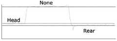
- the bodymay include a rear portion provided in a rod shape having a predetermined length and functioning as a grip portion that can be held by a user; And a head portion extending at an end of the rear portion in an inclined direction with respect to the longitudinal direction of the rear portion.
- the engaging portionmay include a rear side engaging portion located at an end of the rear portion; And a head side engaging portion located at an end of the head portion.
- the rear side engaging portion and the head side engaging portionare provided so as to include a magnet, and the magnet of the rear side engaging portion and the magnet of the head side engaging portion may be installed so that the same polarity is directed to the outside.
- the bodymay be provided in a ring shape having an inner side open.
- the apparatusmay further include a grip portion located in a hole formed on the inner side of the body.
- the outer circumference of the bodymay be provided in a polygonal shape.
- the coupling portionmay be provided in at least one area around the outer periphery of the body.
- a first magnetic bodyprovided as a magnetic body and positioned in a set region at an outer center of the body; And a second magnetic body disposed at a predetermined region of the outer surface of the body and spaced apart from the first magnetic body by a predetermined distance, the second magnetic body being provided as a magnetic body.
- first magnetic body and the second magnetic bodymay be provided as magnets, and the first magnetic body and the second magnetic body may be provided so as to form magnetic force lines in the same direction in the outer region of the body.
- the coupling unitmay include a magnetic body
- the sensing unitmay include a magnetic field sensor capable of sensing a magnetic pattern.
- a controllerthat is provided in a simulation system to allow a user to input a signal to the simulation system, the controller comprising: a first controller; And a second controller that is detachably coupled to the first controller.
- the first controller and the second controllermay further include: a body for providing a skeleton; A coupling unit provided on the body so that the controller can be coupled to another controller; And a sensing unit for sensing a coupled state of the controller.
- the bodymay include a rear portion provided in a rod shape having a predetermined length and functioning as a grip portion that can be held by a user; And a head portion extending at an end of the rear portion in an inclined direction with respect to the longitudinal direction of the rear portion.
- the outer periphery of the bodymay be provided in a polygonal shape and may include a grip portion located in a hole formed on the inner side of the body.
- the coupling unitmay include a magnetic body
- the sensing unitmay include a magnetic field sensor capable of sensing a magnetic pattern.
- an information processing apparatusincluding: a main body for performing a setting operation to derive simulation information including information about a virtual space and a virtual object; And a controller for accepting input of a user and providing input data of the user converted into an electric / electronic signal to the main body, the controller comprising: a first controller; And a second controller that is detachably provided to the first controller, wherein the first controller and the second controller are provided with a simulation system capable of transmitting information on the combined state of the first controller and the second controller have.
- the main bodymay reflect the information on the state of engagement of the controller in the calculation for deriving the simulation information.
- the controllermay further include: a magnetic body provided to the first controller and the second controller, respectively; And a magnetic sensor provided on at least one of the first controller and the second controller.
- a controllerthat improves operability by a user and a simulation system including the controller can be provided.
- a controller capable of changing the coupling type and a simulation system including the controllercan be provided.
- a controllercapable of easily coupling and disengaging with another controller and a simulation system including the controller can be provided.
- FIG. 1is a block diagram of a simulation system in accordance with an embodiment of the present invention.
- FIG. 2is a block diagram showing the configuration of the controller of Fig.
- FIG. 3is a diagram illustrating a first controller according to one embodiment.
- FIG. 4illustrates a second controller according to one embodiment.
- 5is a graph showing the magnetism generated in accordance with the engagement state of the controller.
- FIG. 6is a view showing a first form in which the head side engaging portions of the controller are engaged with each other.
- FIG. 7is a view showing a state in which the first controller and the second controller are not coupled to each other.
- FIG 8is a view showing a second mode in which engaging portions at different positions are coupled to each other in the engaging portion of the first controller and the second controller.
- FIG. 9is a view showing a third embodiment in which the rear side engaging portions of the controller are engaged with each other.
- FIG. 10is a flow chart illustrating steps in which the simulation system of FIG. 1 provides simulation in accordance with one embodiment.
- FIG. 11is a diagram showing a first controller according to another embodiment.
- FIG. 12is a view showing a second controller according to another embodiment.
- FIG. 13is a diagram showing a state in which the first controller and the second controller different from those of the second embodiment are used in the first form.
- FIG. 14is a diagram showing a state in which the first controller and the second controller different from those of the second embodiment are used in the second form.
- 15is a diagram showing a state in which the first controller and the second controller different from those of the second embodiment are used in the third form.
- 16is a view showing a state in which the first controller and the second controller different from those of the second embodiment are used in the fourth form.
- 17is a view showing a state in which the first controller and the second controller different from those of the second embodiment are used in the fifth embodiment.
- FIG. 1is a block diagram of a simulation system in accordance with an embodiment of the present invention.
- the simulation system 1includes a main body 10, a controller 20, and an output device 30.
- the simulation system 1outputs the simulation information in a form in which a setting event occurs in a virtual space so that the user can indirectly experience the setting event.
- Informationcan be provided in a form that the user can perceive through the sensory organs, such as visual information, auditory information, tactile information, and the like. At this time, information may be provided in a form that can be recognized through one or more sensory organs.
- the simulation system 1may provide the user with an indirect experience of events such as war, flight, fighting, sports, and the like.
- the simulation system 1can provide simulation information in a form in which an event occurs between virtual objects in a virtual space.
- the virtual spaceis a space in which an event that is the object of simulation is generated.
- the virtual spacemay be set to apply the same physical rule as the real world, or it may be set to apply a physical rule having a rule different from that of the real world.
- a virtual objectis an object that constitutes a configuration event in virtual space.
- a virtual objectcan be a creature located in a virtual space, an inanimate object, a wind that forms a natural phenomenon, light, and the like.
- the simulation system 1has a form in which an event generated in a virtual space according to a signal input by a user affects a state of a virtual space, and an event generated by a virtual object acts on simulation information transmitted to a user Can be operated.
- the simulation system 1provides the user with an indirect experience of battle in a first-person form
- the virtual spaceis a space set for the occurrence of the battle
- the virtual objectis a space in which the battle is set Surrounding creatures, weapons, terrain, and the like.
- the surrounding creatures, weapons, terrain, etc.can be maintained and modified by the simulation system 1.
- at least one of the surrounding creaturesis a character representing another user, and may be expressed as acting in response to a signal input by another user.
- some of the peripheral organismscan be represented as behaving according to the state set in the simulation system 1.
- the character representing the user in the virtual spacecan change the state of the virtual object by performing a battle action such as a movement corresponding to a signal input by the user, a manipulation of a weapon, or the like.
- a battle actionsuch as a movement corresponding to a signal input by the user, a manipulation of a weapon, or the like.
- an event generated by a virtual objectcan change the state of a character such as an injury to a character.
- the main body 10performs a setting operation to derive simulation information including information on the virtual space and the virtual object.
- the main body 10may include an arithmetic unit for the simulation information arithmetic operation, an algorithm provided for the simulation information arithmetic operation, a date, and the like. Also, the main body 10 can be provided so that simulation information can be transmitted externally.
- the body 10may be implemented as an electronic terminal capable of performing operations for deriving simulation information.
- the electronic terminalmay be implemented as a computer, a portable terminal, a television, a wearable device, or the like.
- the computermay be a notebook computer, a desktop computer, a laptop computer, or the like, on which a web browser (WEB Browser) is mounted.
- WEB Browserweb browser
- a portable terminalis a wireless communication device having portability and mobility.
- the portable terminalis a personal communication system (PCS), a personal digital cellular (PDC), a personal handyphone system (PHS), a personal digital assistant (PDA) International Mobile Telecommunication (IMT) -2000, Code Division Multiple Access (CDMA) -2000, W-CDMA (W-CDMA), Wireless Broadband Internet (Wibro), Smart Phone, Mobile WiMAX Interoperability for Microwave Access), and the like.
- the televisionmay include an Internet Protocol Television (IPTV), an Internet television (TV), a terrestrial TV, a cable TV, and the like.
- IPTVInternet Protocol Television
- TVInternet television
- TVterrestrial TV
- cable TVand the like.
- a wearable deviceis an information processing device of a type that can be directly worn on a human body such as a watch, a glasses, an accessory, a garment, shoes, etc., and can be connected to another server via a network directly or through another information processing device .
- the controller 20accepts the input of the user, and then provides the main body 10 with the data whose input is converted into the electric / electronic signal.
- the data provided by the controller 20may be reflected in computing the simulation information in the main body 10 after being input to the main body 10.
- the output device 30receives the simulation information provided by the main body 10, and then outputs it in a recognizable form through the sensory organ.
- the output device 30may be provided in the form of a display panel, an HMD (Head Mounted Display), or the like to output the simulation information in a form recognizable through visual observation. Further, the output device 30 is provided as a speaker or the like, and can output the simulation information in a recognizable form through the auditory sense. Also, the output device 30 can output the simulation information in a form perceived through two or more senses.
- the simulation system 1is also provided to include two or more output devices 30 so that the body 10 transmits all or a portion of the simulation information to each output device 30 and each output device 30 30 can perform an output in cooperation with each other.
- the output device 30may be provided in a form attached to one side of the main body 10. [ The output device 30 may be provided separately from the main body 10 and may be provided to receive data in a wired or wireless manner with the main body 10.
- FIG. 2is a block diagram showing the configuration of the controller of Fig.
- the controller 20may include an input unit 21, a sensing unit 22, a communication unit 23, a control unit 24, and an output unit 25.
- the input unit 21is provided for the user to perform input.
- the input unit 21may be provided in the form of a button such as a physical button, an electrostatic button, a joystick, a touch screen, an IR sensor, a magnetic switch, an ultrasonic sensor, a distance sensor, have.
- the sensing unit 22senses the engagement state of the controller 20.
- the 'coupled state'may be determined according to at least one of the type of the controller 20 and the other controller 20, the coupling state of the controller 20 and the other controller 20, and the coupling position.
- the coupled statemay be one of a state in which the controller 20 is not coupled to the other controller 20 and a state in which the controller 20 is coupled to the other controller 20.
- the form in which the controller 20 is combined with the other controller 20may include one or more combined states depending on the type and the coupling position of the controller 20 and the other controller 20.
- at least one of the controller 20 and the other controller 20may include a magnetic substance, and the sensing section 22 may include a magnetic field sensor for sensing magnetic patterns.
- the sensing unit 22can sense the coupling state of the controller 20 by sensing the magnetic pattern.
- the magnetic field sensor for detecting the coupling statemay include a magnetic switch.
- the sensing unit 22may sense the tilt, movement, position, etc. of the controller 20, including a magnetic field sensor, a gyro sensor (not shown), an acceleration sensor have.
- the magnetic field sensormay detect the engagement state of the controller 20 and the movement of the controller 20 according to the embodiment.
- the communication unit 23is provided to transmit data to the main body 10. [ For example, the communication unit 23 can transmit the user input received by the input unit 21 to the main body 10. [
- the communication unit 23may transmit the information of the combined state according to the detection of the sensing unit 22 to the main body 10, and the information of the combined state may include information on the change of the combined mode.
- the information on the combined statemay include information on the magnetic pattern sensed by the sensing unit 22.
- the communication unit 23may also receive data transmitted from the main body 10 or another controller 20.
- the communication unit 23may include a communication module supporting at least one of various wired / wireless communication methods.
- the communication modulemay be implemented in the form of a chipset.
- the wireless communication supported by the communication unit 23is wireless fidelity (Wi-Fi), Wi-Fi Direct, Bluetooth, zigbee, infrared data association (IrDA) ), UWB (Ultra Wide Band), NFC (Near Field Communication), etc., and can communicate via a piconet using Bluetooth, UWB (Ultra Wide Band), or a Bluetooth HID profile Lt; / RTI >
- the controller 20can operate in conjunction with another controller 20 via a Bluetooth dongle.
- the wired communication supported by the communication unit 23may include, for example, USB or High Definition Multimedia Interface (HDMI).
- the communication unit 23may be a LAN, a wide area network (WAN), a value added network (VAN), a personal area network (PAN), a mobile communication network Wireless networks such as a mobile radio communication network, a Wibro (Wireless Broadband Internet), a Mobile WiMAX, a HSDPA (High Speed Downlink Packet Access) satellite communication network and an LTE (Long Term Evolution) network.
- WANwide area network
- VANvalue added network
- PANpersonal area network
- Wireless networkssuch as a mobile radio communication network, a Wibro (Wireless Broadband Internet), a Mobile WiMAX, a HSDPA (High Speed Downlink Packet Access) satellite communication network and an LTE (Long Term Evolution) network.
- WibroWireless Broadband Internet
- HSDPAHigh Speed Downlink Packet Access
- LTELong Term Evolution
- the control unit 24can control the components of the controller 20. [
- control unit 24includes a processor such as an MCU (Micro Controller Unit) such as iOS, a Micro-Processing Unit (MPU), an Advanced RISC Machines (ARM), a Central Processing Unit can do.
- MCUMicro Controller Unit
- MPUMicro-Processing Unit
- ARMAdvanced RISC Machines
- the control unit 24can process information sensed by the sensing unit 22 as a user input.
- the control unit 24can process the information on the coupling state of the controller 20, the motion, the inclination, the position, and the like of the controller 20 as user input.
- the detection unit 22detects a change in the coupling state of the controller 20
- the control unit 24can process it as a user input.
- the control unit 24can provide the controller 20 with a function corresponding to a change in the engagement state of the controller 20 or a changed engagement state.
- the control unit 24may cause the signal input through the sensing unit 22 to be transmitted to the main body 10 through the communication unit 23.
- the control unit 24can process the user input inputted to the input unit 21 into different input signals according to the coupled state.
- the control unit 24controls the user input of the A button input in the coupled state of the first type, which will be described later, and the user input of the A button input in the coupled state of the second type, And can be supplied to the main body 10 through the communication unit 23.
- the main body 10may convert the user input inputted to the input unit 21 in accordance with the coupled state of the controller 20, and then reflect the user input in the calculation for calculating the simulation information.
- the main body 10can be operated only when the controller 20 is in the first engaged state and when the controller 20 20) is in the second coupled state, the input signal can be reflected to the simulation information differently in the calculation.
- the output unit 25can output a signal received from the main body 10 in a form recognizable by a user through a sensory organ.
- the output unit 25may be provided with a video output module, an audio output module, a haptic module, or the like.
- a haptic modulemay generate haptic effects such as tactile feedback or force feedback, including vibrations.
- the haptic modulecan generate a haptic effect including vibration according to a user's input, simulation information, and the position or motion of the first controller 100, and can adjust the intensity or pattern of the vibration.
- the output 25may be omitted.
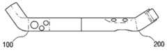
- FIG. 3is a view showing a first controller according to an embodiment
- FIG. 4is a diagram showing a second controller according to an embodiment
- FIG. 5is a graph showing magnetism generated according to a coupling state of a controller.
- the controller 20may be configured as one of the first controller 100 and the second controller 200 or may be configured to include the first controller 100 and the second controller 200.
- the first controller 100may be of a suitable shape when held in the left hand and the second controller 200 may be of a suitable shape when held in the right hand.
- controller 20includes the first controller 100 and the second controller 200 will be described as an example.
- the first controller 100may be of a suitable shape when held in the left hand and the second controller 200 may be of a suitable shape when held in the right hand.
- the first controller 100includes bodies 110 and 120, an input unit 130 and coupling units 140 and 150
- the second controller 200includes a body 210 220, input means 230, and coupling portions 240, 250.
- the second controller 200may be provided in a shape symmetrical to the first controller 100. Repeated descriptions of parts of the second controller 200 that are the same as those of the first control path 100 are omitted.
- the bodies 110 and 120provide the framework of the first controller 100.
- the body 110, 120may include a rear portion 110 and a head portion 120.
- the rear portion 110may be provided in the form of a rod having a set length.
- the rear portion 110is formed in a rod shape, and can be formed into a thickness and a length suitable for grasping in one hand.
- the rear portion 110can be formed by ergonomic design to provide a comfortable and stable grip feeling And may include curvature.
- the rear portion 110may be provided as a portion to be gripped by the user, and may be provided to the grip portion 110.
- the head portion 120may extend in an inclined direction with respect to the longitudinal direction of the rear portion 110 at one side end of the rear portion 110. [ The head portion 120 may have a shorter length than the rear portion 110.
- the first controller 100may have the input means 130 placed in at least one of the rear portion 110 and the head portion 120.
- the input unit 130includes a physical button, an electrostatic button, and the like, a joystick, a touch screen, an IR sensor, a magnetic switch, an ultrasonic sensor, a distance sensor, etc. . ≪ / RTI > According to the embodiment, the input means 130 may be provided at a portion where the user touches the first controller 100 when the user naturally grasps the controller 100. For example, the input means 130 may be provided at the position where the thumb is touched when the four fingers and the palm except for the thumb are rounded and the rear portion 110 is held and the thumb is opened.
- the usercan operate the buttons, the joystick, and the like provided on the input unit 130 by freely moving the thumb with the first controller 100 held by using four fingers and the palm except for the thumb.
- the input means 130may be provided at a position where the remaining four fingers except for the thumb are in contact with each other. For example, it may be provided at a position where detection or interruption is possible, or may be implemented in the form of a trigger.
- the first controller 100may include coupling units 140 and 150 for coupling with the second controller 200.
- the rear side coupling portion 140may be provided at one end of the rear portion 110
- the head side coupling portion 150may be provided at one end of the head portion 120.
- At least one of the rear side coupling portion 140 and the head side coupling portion 150 of the first controller 100is connected to the rear side coupling portion 240 of the second controller 200 and the rear side coupling portion 150 of the second controller 200.
- the head side engaging part 250as shown in FIG.
- the coupling parts 140 and 150are provided with the magnetic bodies 141 and 151 and can be coupled using a magnetic attractive force, but the coupling method is not limited thereto.
- the engaging portions 140 and 150can be engaged using the structural characteristics of the external shape, such as engaging with each other.
- the sensing unit 22may sense the engagement state of the first controller 100.
- the sensing unit 22may be provided to the first controller 100 and the second controller 200 respectively or may be provided to one of the first controller 100 and the second controller 200.
- the sensing unit 22can sense the magnetic pattern of the first controller 100 and the second controller 200 when the first controller 100 and the second controller 200 are coupled to each other, .
- the 'magnetic pattern'may be generated by the magnetic bodies 141 and 151 provided in the coupling parts 140 and 150 as magnetic characteristics sensed according to the coupling state.
- the coupling parts 140 and 150But may be generated by a magnetic body provided at another position of the first controller 100.
- the magnetic patternmay include, for example, a magnetic characteristic depending on the arrangement of the magnets which are differently detected depending on the coupling state or the coupling state.
- the rear side coupling portion 140 and the head side coupling portion 150can generate magnetic forces of different intensities in the coupling process.
- the sensing unit 22may be configured such that one of the rear side coupling unit 140 and the head side coupling unit 150 of the first controller 100 is connected to the rear side coupling unit 240 of the second controller 200, Side coupling portion 250 of the second controller 200. [0050] As shown in FIG. In other words, since the intensity of the magnetic force sensed by the sensing unit 22 varies according to the coupling position, the sensing unit 22 can determine the coupling state of the first controller 100 by sensing the magnetic force.
- the magnetic bodies provided at the coupling portions of the first controller 100 and the second controller 200are provided so that attraction can be generated between the first controller 100 and the second controller 200.
- the magnetic body provided at the coupling portion of the first controller 100 and the second controller 200is a permanent magnet
- the magnetmay be installed so that the same polarity is directed to the outside.
- the magnets of the first controller 100 and the magnets of the second controller 200may be installed so that the polarities thereof are directed to the outside. 3 and 4
- the magnets 141 and 151 provided at both engaging portions of the first controller 100 of FIG. 3are all provided so that their N poles face outward
- the magnets 241 and 251 provided at both coupling parts of the controller 200are all shown with their S poles oriented outward.
- the engaging parts of the first controller 100 and the second controller 200can generate engaging force regardless of the coupling type.
- the magnetic bodymay be provided in the form of an electromagnet, and may be provided to have a polarity as described above when it is operated.
- the rear side coupling portion 140 and the head side coupling portion 150 of the first controller 100may include any one of a lead-in groove and an insertion protrusion.
- the lead-in grooveis a space formed at one end of the coupling portion so that the insertion protrusion can be inserted
- the insertion protrusionis a structure formed at one end of the coupling portion to be inserted into the lead-in groove.
- both engaging portions of one first controller 100may uniformly include one of the receiving grooves or the insertion projections.
- the head side coupling portion 150also has the inlet groove 152
- the head side engaging portion 150may be provided with an insertion hole if the engaging portion 140 has the insertion protrusion.
- each of the engaging portions 140 and 150 of the first controller 100 of FIG. 3includes the inlet grooves 142 and 152, each of the engaging portions 240 and 250 of the two controller 200 has insertion protrusions 242 and 252.
- the first controller 100 and the second controller 200can be coupled to each other regardless of whether the head side coupling portion or the rear side coupling portion.
- the direction in which the first controller 100 and the second controller 200 are coupledmay be determined according to the shape of the lead-in groove and the insertion protrusion.
- the first controller 100 and the second controller 200may be coupled in a direction rotated by 0 degree, 90 degrees, 180 degrees, 270 degrees, if the lead-in groove and the insertion protrusion are formed in a square shape.
- the first controller 100 and the second controller 200are rotated in the direction of 0 °, 60 °, 120 °, 180 °, 240 °, and 300 °, respectively, Can be combined.
- the first controller 100 and the second controller 200are arranged on both hands so that the thumb of each hand touches the input means 130 and 230,
- Each of the head portions 120 and 220may be formed to be bent inward at a predetermined angle with respect to the respective rear portions 110 and 210. That is, when the first controller 100 is held on the left hand so that the thumb of the left hand touches the input means 130, the head 120 is bent in a right angle with respect to the rear portion 110
- the second controller 200is grasped by the right hand so that the thumb of the right hand touches the input means 230, the head portion 220 forms a predetermined angle to the left with respect to the rear portion 210, . ≪ / RTI >
- 6 to 9are views showing a state in which the first controller and the second controller are used.
- FIG. 6is a view showing a first embodiment in which the head side engaging portions of the controllers 100 and 200 are engaged.
- the head side coupling unit 150 of the first controller 100 and the head side coupling unit 250 of the second controller 200are combined to implement the first mode.
- the usercan hold the first controller 100 and the second controller 200 in a form in which the thumbs of both hands face each other, and control the input means 130 and 230 with the thumb. It is similar to the pad type of game device, and stable posture of both hands is possible, so that comfortable control is possible.
- At least one of the first controller 100 and the second controller 200may include an acceleration sensor and a gyro sensor to perform a role of a steering wheel of a vehicle in a racing game.
- FIG. 7is a view showing a state in which the first controller and the second controller are not coupled to each other.
- first controller 100 and the second controller 200may be used or may be used in two or more separate states.
- the usercan control the simulation by holding both the first controller 100 and the second controller 200 in both hands.
- the first controller 100 and the second controller 200are equipped with a motion recognition sensor such as an acceleration sensor and a gyro sensor, so that the movement of both hands can be individually recognized.
- the usermay control the simulation using only one of the first controller 100 and the second controller 200.
- the controllers 100 and 200 according to the combined state of FIG. 7can perform functions such as guns and knives in the VR game.
- FIG 8is a view showing a second mode in which engaging portions at different positions are coupled to each other in the engaging portion of the first controller and the second controller.
- the second embodimentis different from the first embodiment in that the rear side engaging part 140 of the first controller 100 and the head side engaging part 250 of the second controller 200 are engaged or the head side engaging part 150 And the rear side coupling portion 240 of the second controller 200 may be combined.
- the second formcan serve as a rifle.
- At least one of the first controller 100 and the second controller 200includes an acceleration sensor and a gyro sensor to provide a function of aiming a target in the game according to the direction of the controller 100 or 200 can do.
- FIG. 9is a view showing a third embodiment in which the rear side engaging portions of the controller are engaged with each other.
- the controller 100, 200 combined in the third formmay be squeezed over the user's shoulders, Can play the same role.
- various types of objectscan be similarly implemented by combining the controller 20 in various forms. Thereby, the user can feel a higher sense of reality depending on the coupling state of the controller 20 in using the simulation system 1.
- the main body 10receives the information on the coupled state sensed by the sensing unit 22 and can generate the simulation information based on the received information on the coupled state.
- the information of the combined statemay include information on the change of the combined state, and the main body 10 may process the change of the combined state of the controller 20 as a user input. At this time, the main body 10 can provide a function corresponding to the changed coupling state.
- the main body 10may receive user inputs processed with different input signals according to the coupled state in the controller 20. [ In addition, the main body 10 can receive the information of the coupled state and the user input inputted to the input unit 21 of the controller 20, and process the user input into different input signals according to the coupled state.
- the body 10processes the change in the state of the joining as a user input to the change in weapon . That is, when the main body 10 receives the information on the change of the engagement state, it can provide the weapon corresponding to the changed engagement state.
- the body 10may provide a pistol in response to a disengaged condition, provide a rifle in response to a second form, or provide a rocket launcher in response to a third form.
- the simulation system 1can quickly detect a change in the state of the coupled state and a changed state of the coupled state, and provide a corresponding simulation.
- the userwhen the controller 20 is applied to a battle game, the user can be provided with the function of rapidly changing the state of the engagement of the controller 20, thereby rapidly changing the weapon used in the virtual battle.
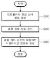
- FIG. 10is a flow chart illustrating steps in which the simulation system of FIG. 1 provides simulation in accordance with one embodiment.
- the controller 20 of the simulation system 1may be provided including the first controller 100 and the second controller 200.
- the controller 20senses the pattern of the magnetic body according to the coupling or separation, and generates the sensed information of the coupling state through the magnetic pattern (S101).
- the communication unit 23can transmit the generated information of the coupled state to the main body 10 (S102).
- the main body 10can generate simulation information based on the received coupling state information (S103).
- the information of the combined statemay include information about the change of the combined state, at which time the body 10 may process the change of the combined state as a user input and generate simulation information accordingly have.
- the main body 10may reflect the coupling state in the simulation information in a form in which the equipment of the character representing the user is replaced in the simulation.
- the method of providing a simulation according to the embodiments described with reference to FIG. 10may also be implemented in the form of a computer-readable medium storing instructions and data executable by a computer.
- the command and datamay be stored in the form of program code, and when executed by the processor, a predetermined program module may be generated to perform a predetermined operation.
- the computer-readable mediumcan be any available media that can be accessed by a computer and includes both volatile and nonvolatile media, removable and non-removable media.
- the computer-readable mediumcan also be a computer storage medium, which can be volatile and non-volatile, implemented in any method or technology for storage of information such as computer readable instructions, data structures, program modules or other data, Volatile, removable and non-removable media.
- the computer recording mediummay be a magnetic storage medium such as an HDD and an SSD, an optical recording medium such as a CD, a DVD and a Blu-ray Disc, or a memory included in a server accessible via a network.
- the method of providing a simulation according to the embodiments described with reference to FIG. 10may be implemented as a computer program (or a computer program product) including instructions executable by a computer.
- a computer programincludes programmable machine instructions that are processed by a processor and can be implemented in a high-level programming language, an object-oriented programming language, an assembly language, or a machine language have.
- the computer programmay also be recorded on a computer readable recording medium of a type (e.g., memory, hard disk, magnetic / optical medium or solid-state drive).
- the method of providing a simulation according to the embodiments described with reference to FIG. 10can be implemented by a computer program as described above being executed by a computing device.
- the computing devicemay include a processor, a memory, a storage device, a high-speed interface connected to the memory and a high-speed expansion port, and a low-speed interface connected to the low-speed bus and the storage device.
- Each of these componentsis connected to each other using a variety of buses and can be mounted on a common motherboard or mounted in any other suitable manner.
- processormay process instructions within the computing device, such as displaying graphics information to provide a graphical user interface (GUI) on an external input, output device, such as a display connected to a high speed interface And commands stored in the memory or storage device.
- GUIgraphical user interface
- multiple processors and / or multiple bussesmay be used with multiple memory and memory types as appropriate.
- the processormay also be implemented as a chipset comprised of chips comprising multiple independent analog and / or digital processors.
- the memoryalso stores information within the computing device.
- the memorymay comprise volatile memory units or a collection thereof.
- the memorymay be comprised of non-volatile memory units or a collection thereof.
- the memorymay also be another type of computer readable medium such as, for example, a magnetic or optical disk.
- the storage devicecan provide a large amount of storage space to the computing device.
- the storage devicemay be a computer readable medium or a configuration including such a medium and may include, for example, devices in a SAN (Storage Area Network) or other configurations, and may be a floppy disk device, a hard disk device, Or a tape device, flash memory, or other similar semiconductor memory device or device array.
- SANStorage Area Network
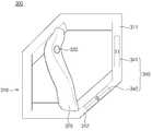
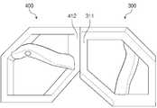
- FIG. 11is a diagram showing a first controller according to another embodiment.
- the first controller 300may include a body 310, a grip portion 320, an input means 330, and a coupling portion 340.
- the first controller 300may be provided in a form in which the user can easily operate the left hand.
- the body 310provides the framework of the first controller 300.
- the body 310may be provided in the form of a ring having an inner side open.
- the outer periphery of the body 310may be provided in a polygonal shape.
- FIG. 11shows an example in which the outer periphery of the body 310 is provided in a hexagonal shape.
- the hole formed inside the body 310may be formed to have a size such that the user's hand can be inserted.
- the shape of the hole formed inside the body 310may correspond to the shape of the outer periphery of the body 310 or may be provided in a shape different from the outer periphery of the body 310.
- the grip portion 320is located in a hole formed in the inside of the body 310 and can be provided as a portion where the user holds the first controller 300.
- the grip portion 320may be biased to one side in a hole formed in the inside of the body 310.
- the grip portion 320is positioned to the left in the hole formed in the inside of the body 310, and the body 310 is formed to be smaller than the region where the region located on the outer side with respect to the grip portion 320 is located on the right side .
- the outer surface of the body 310 positioned on the outer side of the region where the upper end of the grip portion 320 is connectedis referred to as a first surface and the second surface to the sixth surface sequentially along the clockwise direction, And the grip portion 320 is connected to an area located on the inner side of the first and fifth surfaces.
- the grip portion 320may be provided so that a certain region protrudes forward with reference to FIG.
- the inner surface of the body 310may be inclined inwardly as the area connected to the grip 320 moves from the front to the rear, and the grip portion 320 may have a central region protruding forward May be connected to the body 310.
- the usercan conveniently hold the grip portion 320 in a manner that the thumb is positioned on the right side and the remaining four fingers positioned on the left side.
- the input means 330may be included in the input unit 21 to receive user input.
- the input means 330may be provided at a portion where the user touches the first controller 300 when the user naturally grasps the first controller 300.
- the input means 330may be located in one area of the outer surface of the grip portion 320.
- the input means 330is located at the upper end of the grip portion 320 adjacent to the first surface and can be provided operatively through the thumb when the user holds the grip portion 320.
- the input means 330may be positioned in the region direction in which the first surface and the second surface are adjacent to each other.
- the input means 330may be located on the inner side of the region where the first and second sides of the body 310 are adjacent to each other.
- the coupling portion 340allows the first controller 300 to be coupled to the second controller 400.
- the engaging portion 340may be provided in at least one area around the outer periphery of the body 310.
- the coupling portion 340may include at least one magnetic body 341, 342.
- the coupling portion 340may include a first magnetic body 341 and a second magnetic body 342.
- the magnetic bodies 341 and 342can be positioned adjacent to a part of the outer surface of the body 310.
- the magnetic bodies 341 and 342may be provided in a state of being accommodated inside a part of the area of the body 310 so as to be adjacent to a part of the area of the outer surface of the body 310, And may be fixedly provided to the body 310 in a state of being exposed toward the side.
- the first magnetic body 341 and the second magnetic body 342may be positioned apart from each other by a predetermined distance.
- the first magnetic body 341is located in the first coupling region 311 among the outer sides of the body 310 and the second magnetic body 342 is located in the second coupling region 312 ).
- the first engagement region 311is provided as an area having one of the first to sixth surfaces
- the second engagement region 312is provided as a And may be a region having one of the first to sixth faces.
- 11shows a case where a region having a third side is provided as a first coupling region 311 and a region having a fourth side is provided as a second coupling region 312.
- the first magnetic body 341 and the second magnetic body 342may be provided so as to form magnetic force lines in the same direction in the outer region of the body 310 when the first controller 300 is coupled with the second controller 400 have.
- the poles of the magnetsmay be positioned to face the same direction. 11, the N-pole is positioned outside the body 310 and the S-pole is positioned inside the body 310.
- the first magnetic body 341 and the second magnetic body 342may be arranged in such a manner that the S pole is positioned outside the body 310.
- first magnetic body 341 and the second magnetic body 342may be provided as a metallic material generating attraction between the magnet and the magnet.
- one of the first magnetic body 341 and the second magnetic body 342may be provided as a permanent magnet or an electromagnet, and the other may be provided as a metal material.
- FIG. 12is a view showing a second controller according to another embodiment.
- the second controller 400may include a body 410, a grip portion 420, an input means 430, and a coupling portion 440.
- the second controller 400can be provided in a form in which the user can easily operate through the right hand.
- the body 410provides the framework of the second controller 400.
- the body 410may be provided in a ring shape with an inner side open.
- the outer periphery of the body 410may be provided in a polygonal shape.
- FIG. 12shows an example in which the outer periphery of the body 410 is provided in a hexagonal shape.
- the hole formed inside the body 410may be formed to have a size such that the user's hand can be inserted.
- the shape of the hole formed inside the body 410may correspond to the shape of the outer periphery of the body 410 or may be provided in a shape different from the outer periphery of the body 410.
- the body 410may be provided in a shape symmetrical to the body 410 of the first controller 300.
- the grip portion 420may be disposed in a hole formed inside the body 410 and may be provided as a portion for the user to hold the second controller 400.
- the grip portion 420may be biased to one side in the hole formed inside the body 410.
- the grip portion 420is positioned to the right in a hole formed on the inner side of the body 410, and the body 410 is formed to be smaller than a region where the right side portion of the body 410 is positioned on the left side with respect to the grip portion 420 .
- the outer surface of the body 410 positioned on the outer side of the region where the upper end of the grip portion 420 is connectedis referred to as a first surface and the second surface to the sixth surface are sequentially referred to as a counterclockwise direction, A shape in which the grip portion 420 is connected to an area located on the inner side of the first and fifth surfaces is shown.
- the grip portion 420may be provided such that a certain region protrudes forward with reference to FIG.
- the inner surface of the body 410may be inclined inwardly as the area connected to the grip portion 420 increases from the front to the rear, and the grip portion 420 may have a shape in which the central region protrudes forward And may be connected to the body 410.
- the usercan conveniently hold the grip portion 420 in such a manner that the thumb is positioned to the left and the remaining four fingers are positioned to the right.
- the input unit 430may be included in the input unit 21 to receive a user input.
- the input means 430may be provided at a portion where the user touches the second controller 400 when the user naturally grasps the second controller 400.
- the input means 430may be located in one area of the outer surface of the grip portion 420.
- the input means 430may be located at the upper end of the grip portion 420 adjacent to the first surface and may be operably provided through the thumb when the user grips the grip portion 420.
- the input means 430may be positioned in the area direction in which the first surface and the second surface are adjacent to each other.
- the input means 430may be located on the inner surface of the region where the first surface and the second surface are adjacent to each other in the body 410.
- the coupling portion 440allows the second controller 400 to be coupled to the first controller 300.
- the coupling portion 440may include at least one magnetic body 441, 442, 443, 444.
- the coupling portion 440may include a first magnetic body 441, a second magnetic body 442, a third magnetic body 443, and a fourth magnetic body 444.
- the magnetic bodies 441, 442, 443, and 444may be positioned adjacent to a part of the outer surface of the body 410.
- the magnetic bodies 441, 442, 443, and 444may be provided in a state of being accommodated inside a part of the area of the body 410 so as to be adjacent to a part of the area of the outer surface of the body 410, 410 to the outside of the body 410.
- the body 410may be fixedly provided in the form of being exposed toward the outer surface of the body 410.
- the first magnetic body 441, the second magnetic body 442, the third magnetic body 443, and the fourth magnetic body 444may be positioned apart from each other by a predetermined distance.
- the first magnetic body 441is located in the first coupling region 411 among the outer sides of the body 410 and the second magnetic body 442 is located in the second coupling region 412
- the first coupling region 411, the second coupling region 412, the third coupling region 413, and the fourth coupling region 414are formed in a hexagonal shape, respectively, when the outer surface of the body 410 is provided in a hexagonal shape. It may be provided as an area having one of the first to sixth surfaces so as not to overlap.
- a region having a third sideis provided as a first coupling region 411
- a region having a fifth sideis provided as a second coupling region 412
- a region having a sixth sideis provided as a third coupling region 411
- the region having the first sideis provided as the fourth coupling region 414.
- the first magnetic body 441, the second magnetic body 442, the third magnetic body 443, and the fourth magnetic body 444are coupled to the body 410, So that the magnetic force lines are formed in the same direction in the outer region of the magnetoresistive element.
- first magnetic body 441, the second magnetic body 442, the third magnetic body 443, and the fourth magnetic body 444are provided as permanent magnets or electromagnets, Lt; / RTI > At this time, the first controller 441, the second magnetic body 442, the third magnetic body 443, and the fourth magnetic body 444 are controlled such that the second controller 400 generates an attraction force between the first controller 300 442, 443, and 444 of the first controller 300 so that the magnetic poles thereof are opposite to each other.
- FIG. 12shows a state in which an S pole is positioned outside the body 410 and an N pole is located inside the body 410.
- FIG. 11, the first magnetic body 441, the second magnetic body 442, the third magnetic body 442, The fourth magnetic body 444 and the fourth magnetic body 444may be arranged in such a manner that the N pole is positioned outside the body 410.
- the first magnetic body 441, the second magnetic body 442, the third magnetic body 443, and the fourth magnetic body 444may be provided with a metallic material generating attraction between the magnet and the magnet.
- a part of the first magnetic body 441, the second magnetic body 442, the third magnetic body 443 and the fourth magnetic body 444may be provided as permanent magnets or electromagnets and the rest may be provided as a metal material .
- the coupling unit 340 provided in the first controller 300 and the coupling unit 440 provided in the second controller 400are coupled to the coupling units 340 and 440 according to the coupling type of the controllers 300 and 400, Are generated so as to be generated differently similarly to Fig.
- the sensing unit 22 provided to one of the first controller 300 and the second controller 400 or provided to the first controller 300 and the second controller 400is connected to the controller 300 And 400, and the communication unit 23 provides this to the main body 10. Operations of the main body 10 and the controllers 300 and 400 according to the change of the coupled state are the same as or similar to those described above with reference to FIGS. 1 to 10, and thus repeated description will be omitted.
- FIG. 13 to 17are diagrams showing a state in which the first controller and the second controller according to the second embodiment are used.
- FIG. 13is a diagram showing a state in which the first controller and the second controller different from those of the second embodiment are used in the first form.
- the first coupling region 311 of the first controller 300 and the first coupling region 411 of the second controller 400may be coupled to form a first type.
- the usercan grasp the first controller 300 and the second controller 400 in a form in which the thumbs of both hands face each other, and control the input means 330 and 430 with the thumb. It is similar to the pad type of game device, and stable posture of both hands is possible, so that comfortable control is possible.
- At least one of the first controller 300 and the second controller 400may include an acceleration sensor and a gyro sensor to perform a role of a steering wheel of a car in a racing game.
- FIG. 14is a diagram showing a state in which the first controller and the second controller different from those of the second embodiment are used in the second form.
- the first coupling region 311 of the first controller 300 and the second coupling region 412 of the second controller 400may be coupled to form a second type.
- the first controller 300may be located in front of the second controller 400 based on the user.
- the left hand holding the first controller 300is aimed at the front side, and the right hand holding the second controller 400 can be put in a state of being held.
- the second formcan act like a rocket launcher.
- At least one of the first controller 300 and the second controller 400includes an acceleration sensor and a gyro sensor to provide a function of aiming a target in the game according to the direction of the controller 300 or 400 can do.
- 15is a diagram showing a state in which the first controller and the second controller different from those of the second embodiment are used in the third form.
- the first coupling region 311 of the first controller 300 and the third coupling region 413 of the second controller 400may be coupled to form a third type.
- the first controller 300may be located in front of the second controller 400 based on the user.
- the left hand and the right hand holding the first controller 300can be directed toward the front.
- the third formcan serve as a rifle.
- At least one of the first controller 300 and the second controller 400includes an acceleration sensor and a gyro sensor to provide a function of aiming a target in the game according to the direction of the controller 300 or 400 can do.
- 16is a view showing a state in which the first controller and the second controller different from those of the second embodiment are used in the fourth form.
- the second coupling region 312 of the first controller 300 and the third coupling region 413 of the second controller 400may be coupled to form a fourth type.
- the first controller 300may be located in front of the second controller 400 based on the user.
- the left hand and the right hand holding the first controller 300can be directed toward the front.
- the fourth formmay serve as a rifle.
- At least one of the first controller 300 and the second controller 400includes an acceleration sensor and a gyro sensor to provide a function of aiming a target in the game according to the direction of the controller 300 or 400 can do.
- 17is a view showing a state in which the first controller and the second controller different from those of the second embodiment are used in the fifth embodiment.
- the second coupling region 312 of the first controller 300 and the fourth coupling region 314 of the second controller 400may be coupled to form a fifth mode.
- the first controller 300may be located in front of or above the second controller 400 based on the user.
- the left hand and right hand holding the first controller 300can be placed in the vertical direction.
- the fifth modecan serve as a sword, a baseball bat, or the like held by both hands.
- At least one of the first controller 300 and the second controller 400includes an acceleration sensor and a gyro sensor to provide a function of aiming a target in the game according to the direction of the controller 300 or 400 can do.
- " part "refers to a hardware component such as software or a field programmable gate array (FPGA) or an ASIC, and " part "
- 'part'is not meant to be limited to software or hardware.
- &Quot; to "may be configured to reside on an addressable storage medium and may be configured to play one or more processors.
- 'parts'may refer to components such as software components, object-oriented software components, class components and task components, and processes, functions, , Subroutines, segments of program patent code, drivers, firmware, microcode, circuitry, data, databases, data structures, tables, arrays, and variables.
- components and componentsmay be implemented to play back one or more CPUs in a device or a secure multimedia card.
- main body 20controller
- first controller 110rear part
Landscapes
- Engineering & Computer Science (AREA)
- Multimedia (AREA)
- Human Computer Interaction (AREA)
- General Engineering & Computer Science (AREA)
- Theoretical Computer Science (AREA)
- Physics & Mathematics (AREA)
- General Physics & Mathematics (AREA)
- User Interface Of Digital Computer (AREA)
Abstract
Translated fromKoreanDescription
Translated fromKorean본 발명은 컨트롤러 및 이를 포함하는 시뮬레이션 시스템에 관한 것으로, 보다 상세하게는 사용과정에서 결합 상태가 변경될 수 있는 컨트롤러 및 이를 포함하는 시뮬레이션 시스템에 관한 것이다.BACKGROUND OF THE
최근 들어, 영상 분야의 비약적인 발전으로 인해 다양한 영상 기술이 개발 및 응용되고 있으며, 특히, 가상현실 영상을 생성하고, 생성된 가상현실 영상을 사용자 단말을 통해 재생하고 관람하는 기술이 등장하고 있다.2. Description of the Related Art [0002] In recent years, a variety of image technologies have been developed and applied due to the rapid development of the image field. In particular, technologies for generating virtual reality images and reproducing and viewing the generated virtual reality images through user terminals are emerging.
가상현실(Virtual Reality: VR)이라 함은 실제 현실은 아니지만 사용자가 현실과 같은 환경을 3차원적인 시각(Sight)을 통해 경험할 수 있도록 하는 시뮬레이션 기술을 의미하며, 상기 가상현실은 가상의 공간과 사물을 기반으로 현실 세계만으로는 얻기 어려운 부가적인 체험이나 정보들을 사용자에게 제공할 수 있는 특징을 가지고 있다.Virtual Reality (VR) refers to a simulation technique that allows a user to experience an environment such as a reality through a three-dimensional sight (Sight), which is not an actual reality, , It is possible to provide users with additional experiences or information that can not be obtained only in the real world.
본 발명은 사용자에 의한 조작성이 향상되는 컨트롤러 및 이를 포함하는 시뮬레이션 시스템을 제공하기 위한 것이다.The present invention is intended to provide a controller that improves operability by a user and a simulation system including the same.
또한, 결합 형태가 변경 가능한 컨트롤러 및 이를 포함하는 시뮬레이션 시스템을 제공하기 위한 것이다.The present invention also provides a controller capable of changing the coupling type and a simulation system including the same.
또한, 다른 컨트롤러와 용이하게 결합 및 분리가 가능한 컨트롤러 및 이를 포함하는 시뮬레이션 시스템을 제공하기 위한 것이다.It is also intended to provide a controller and a simulation system including the controller that can be easily combined and separated with other controllers.
본 발명의 일 측면에 따르면, 시뮬레이션 시스템에 제공되어, 상기 시뮬레이션 시스템으로 사용자가 신호를 입력할 수 있도록 하는 컨트롤러에 있어서,According to an aspect of the invention, there is provided a controller for providing a user with a signal to a simulation system, the controller being provided with a simulation system,
골격을 제공하는 바디; 상기 바디에 구비되어 상기 컨트롤러가 다른 컨트롤러와 결합될 수 있도록 하는 결합부; 및 상기 컨트롤러의 결합 상태를 감지하는 감지부를 포함하는 컨트롤러가 제공될 수 있다.A body providing the skeleton; A coupling unit provided on the body so that the controller can be coupled to another controller; And a controller for detecting a coupled state of the controller.
또한, 상기 바디는, 설정 길이의 막대 형상으로 제공되어 사용자가 잡을 수 있는 그립부로 기능하는 리어부; 및 상기 리어부의 일측 단부에서 상기 리어부의 길이 방향에 대해 경사진 방향으로 연장되는 헤드부를 포함할 수 있다.The body may include a rear portion provided in a rod shape having a predetermined length and functioning as a grip portion that can be held by a user; And a head portion extending at an end of the rear portion in an inclined direction with respect to the longitudinal direction of the rear portion.
또한, 상기 결합부는, 상기 리어부의 단부에 위치되는 리어측 결합부; 및 상기 헤드부의 단부에 위치되는 헤드측 결합부를 포함할 수 있다.Further, the engaging portion may include a rear side engaging portion located at an end of the rear portion; And a head side engaging portion located at an end of the head portion.
또한, 상기 리어측 결합부 및 상기 헤드측 결합부는 자석을 포함하도록 제공되되, 상기 리어측 결합부의 자석과 상기 헤드측 결합부의 자석은 동일한 극성이 바깥쪽을 향하도록 설치될 수 있다.In addition, the rear side engaging portion and the head side engaging portion are provided so as to include a magnet, and the magnet of the rear side engaging portion and the magnet of the head side engaging portion may be installed so that the same polarity is directed to the outside.
또한, 상기 바디는 내측이 뚫려 있는 링 형상으로 제공될 수 있다.Further, the body may be provided in a ring shape having an inner side open.
또한, 상기 바디의 내측에 형성된 홀에 위치되는 그립부를 더 포함할 수 있다.The apparatus may further include a grip portion located in a hole formed on the inner side of the body.
또한, 상기 바디의 외측 둘레는 다각형 형상으로 제공될 수 있다.Also, the outer circumference of the body may be provided in a polygonal shape.
또한, 상기 결합부는 상기 바디의 외측 둘레의 적어도 하나 이상의 영역에 제공될 수 있다.In addition, the coupling portion may be provided in at least one area around the outer periphery of the body.
또한, 자성체로 제공되고 상기 바디의 외측면 가운데 설정 영역에 위치되는 제1 자성체; 및 상기 제1 자성체와 설정 거리 이격 되어 상기 바디의 외측면 가운데 설정 영역에 위치되고, 자성체로 제공되는 제2 자성체를 포함할 수 있다.A first magnetic body provided as a magnetic body and positioned in a set region at an outer center of the body; And a second magnetic body disposed at a predetermined region of the outer surface of the body and spaced apart from the first magnetic body by a predetermined distance, the second magnetic body being provided as a magnetic body.
또한, 상기 제1 자성체와 상기 제2 자성체는 자석으로 제공되되, 상기 제1 자성체와 상기 제2 자성체는 상기 바디의 외측 영역에서 동일한 방향으로 자기력선이 형성되도록 제공될 수 있다.Also, the first magnetic body and the second magnetic body may be provided as magnets, and the first magnetic body and the second magnetic body may be provided so as to form magnetic force lines in the same direction in the outer region of the body.
또한, 상기 결합부는 자성체를 포함하고, 상기 감지부는 자기 패턴을 감지할 수 있는 자계 센서를 포함할 수 있다.Also, the coupling unit may include a magnetic body, and the sensing unit may include a magnetic field sensor capable of sensing a magnetic pattern.
본 발명의 다른 측면에 따르면, 시뮬레이션 시스템에 제공되어, 상기 시뮬레이션 시스템으로 사용자가 신호를 입력할 수 있도록 하는 컨트롤러에 있어서, 상기 컨트롤러는, 제1 컨트롤러; 및 상기 제1 컨트롤러와 결합 및 분리 가능하게 제공되는 제2 컨트롤러를 포함할 수 있다.According to another aspect of the present invention there is provided a controller that is provided in a simulation system to allow a user to input a signal to the simulation system, the controller comprising: a first controller; And a second controller that is detachably coupled to the first controller.
또한, 상기 제1 컨트롤러 및 상기 제2 컨트롤러는, 골격을 제공하는 바디; 상기 바디에 구비되어 상기 컨트롤러가 다른 컨트롤러와 결합될 수 있도록 하는 결합부; 및 상기 컨트롤러의 결합 상태를 감지하는 감지부를 포함할 수 있다.The first controller and the second controller may further include: a body for providing a skeleton; A coupling unit provided on the body so that the controller can be coupled to another controller; And a sensing unit for sensing a coupled state of the controller.
또한, 상기 바디는, 설정 길이의 막대 형상으로 제공되어 사용자가 잡을 수 있는 그립부로 기능하는 리어부; 및 상기 리어부의 일측 단부에서 상기 리어부의 길이 방향에 대해 경사진 방향으로 연장되는 헤드부를 포함할 수 있다.The body may include a rear portion provided in a rod shape having a predetermined length and functioning as a grip portion that can be held by a user; And a head portion extending at an end of the rear portion in an inclined direction with respect to the longitudinal direction of the rear portion.
또한, 상기 바디의 외측 둘레는 다각형 형상으로 제공되고, 상기 바디의 내측에 형성된 홀에 위치되는 그립부를 더 포함할 수 있다.The outer periphery of the body may be provided in a polygonal shape and may include a grip portion located in a hole formed on the inner side of the body.
또한, 상기 결합부는 자성체를 포함하고, 상기 감지부는 자기 패턴을 감지할 수 있는 자계 센서를 포함할 수 있다.Also, the coupling unit may include a magnetic body, and the sensing unit may include a magnetic field sensor capable of sensing a magnetic pattern.
본 발명의 또 다른 측면에 따르면, 설정 연산을 수행하여 가상 공간 및 가상 객체에 관한 정보를 포함하는 시뮬레이션 정보를 도출하는 본체; 및 사용자의 입력을 받아 들인 후, 사용자의 입력이 전기 전자적 신호로 변환된 데이터를 상기 본체에 제공하는 컨트롤러를 포함하되, 상기 컨트롤러는, 제1 컨트롤러; 및 상기 제1 컨트롤러와 결합 및 분리 가능하게 제공되는 제2 컨트롤러를 포함하고, 상기 본체로 상기 제1 컨트롤러와 상기 제2 컨트롤러의 결합 상태에 관한 정보를 송신 가능하게 제공되는 시뮬레이션 시스템이 제공될 수 있다.According to another aspect of the present invention, there is provided an information processing apparatus including: a main body for performing a setting operation to derive simulation information including information about a virtual space and a virtual object; And a controller for accepting input of a user and providing input data of the user converted into an electric / electronic signal to the main body, the controller comprising: a first controller; And a second controller that is detachably provided to the first controller, wherein the first controller and the second controller are provided with a simulation system capable of transmitting information on the combined state of the first controller and the second controller have.
또한, 상기 본체는 상기 컨트롤러의 결합 상태에 관한 정보를 시뮬레이션 정보 도출을 위한 연산에 반영할 수 있다.In addition, the main body may reflect the information on the state of engagement of the controller in the calculation for deriving the simulation information.
또한, 상기 컨트롤러는, 상기 제1 컨트롤러 및 상기 제2 컨트롤러에 각각 제공되는 자성체; 및 상기 제1 컨트롤러 및 상기 제2 컨트롤러 중 적어도 하나에 제공되는 자기 센서를 포함할 수 있다.The controller may further include: a magnetic body provided to the first controller and the second controller, respectively; And a magnetic sensor provided on at least one of the first controller and the second controller.
본 발명의 일 실시 예에 의하면, 사용자에 의한 조작성이 향상되는 컨트롤러 및 이를 포함하는 시뮬레이션 시스템이 제공될 수 있다.According to an embodiment of the present invention, a controller that improves operability by a user and a simulation system including the controller can be provided.
또한, 결합 형태가 변경 가능한 컨트롤러 및 이를 포함하는 시뮬레이션 시스템이 제공될 수 있다.Further, a controller capable of changing the coupling type and a simulation system including the controller can be provided.
또한, 다른 컨트롤러와 용이하게 결합 및 분리가 가능한 컨트롤러 및 이를 포함하는 시뮬레이션 시스템이 제공될 수 있다.In addition, a controller capable of easily coupling and disengaging with another controller and a simulation system including the controller can be provided.
도 1은 본 발명의 일 실시 예에 따른 시뮬레이션 시스템의 블록도이다.1 is a block diagram of a simulation system in accordance with an embodiment of the present invention.
도 2는 도 1의 컨트롤러의 구성을 나타내는 블록도이다.2 is a block diagram showing the configuration of the controller of Fig.
도 3은 일 실시 예에 따른 제1 컨트롤러를 나타내는 도면이다.3 is a diagram illustrating a first controller according to one embodiment.
도 4는 일 실시 예에 따른 제2 컨트롤러를 나타내는 도면이다.4 illustrates a second controller according to one embodiment.
도 5는 컨트롤러의 결합 상태에 따라 발생되는 자성을 나타내는 그래프이다.5 is a graph showing the magnetism generated in accordance with the engagement state of the controller.
도 6은 컨트롤러의 헤드측 결합부끼리 결합한 제1형태를 나타내는 도면이다.6 is a view showing a first form in which the head side engaging portions of the controller are engaged with each other.
도 7은 제1 컨트롤러와 제2 컨트롤러가 서로 결합되지 않은 상태를 나타내는 도면이다.7 is a view showing a state in which the first controller and the second controller are not coupled to each other.
도 8은 제1 컨트롤러와 제2 컨트롤러의 결합부 중 서로 다른 위치의 결합부가 결합된 제2형태를 나타내는 도면이다.8 is a view showing a second mode in which engaging portions at different positions are coupled to each other in the engaging portion of the first controller and the second controller.
도 9는 컨트롤러의 리어측 결합부끼리 결합된 제3형태를 나타내는 도면이다.9 is a view showing a third embodiment in which the rear side engaging portions of the controller are engaged with each other.
도 10은 일 실시 예에 따라 도 1의 시뮬레이션 시스템이 시뮬레이션을 제공하는 단계를 나타내는 순서도이다.10 is a flow chart illustrating steps in which the simulation system of FIG. 1 provides simulation in accordance with one embodiment.
도 11은 다른 실시 예에 따른 제1 컨트롤러를 나타내는 도면이다.11 is a diagram showing a first controller according to another embodiment.
도 12는 다른 실시 예에 따른 제2 컨트롤러를 나타내는 도면이다.12 is a view showing a second controller according to another embodiment.
도 13은 제2 실시 예에 다른 제1 컨트롤러와 제2 컨트롤러가 제1 형태로 사용되는 상태를 나타내는 도면이다.13 is a diagram showing a state in which the first controller and the second controller different from those of the second embodiment are used in the first form.
도 14는 제2 실시 예에 다른 제1 컨트롤러와 제2 컨트롤러가 제2 형태로 사용되는 상태를 나타내는 도면이다.14 is a diagram showing a state in which the first controller and the second controller different from those of the second embodiment are used in the second form.
도 15는 제2 실시 예에 다른 제1 컨트롤러와 제2 컨트롤러가 제3 형태로 사용되는 상태를 나타내는 도면이다.15 is a diagram showing a state in which the first controller and the second controller different from those of the second embodiment are used in the third form.
도 16은 제2 실시 예에 다른 제1 컨트롤러와 제2 컨트롤러가 제4 형태로 사용되는 상태를 나타내는 도면이다.16 is a view showing a state in which the first controller and the second controller different from those of the second embodiment are used in the fourth form.
도 17은 제2 실시 예에 다른 제1 컨트롤러와 제2 컨트롤러가 제5 형태로 사용되는 상태를 나타내는 도면이다.17 is a view showing a state in which the first controller and the second controller different from those of the second embodiment are used in the fifth embodiment.
이하, 본 발명의 실시 예를 첨부된 도면들을 참조하여 더욱 상세하게 설명한다. 본 발명의 실시 예는 여러 가지 형태로 변형할 수 있으며, 본 발명의 범위가 아래의 실시 예들로 한정되는 것으로 해석되어서는 안 된다. 본 실시 예는 당업계에서 평균적인 지식을 가진 자에게 본 발명을 더욱 완전하게 설명하기 위해 제공되는 것이다. 따라서 도면에서의 요소의 형상은 보다 명확한 설명을 강조하기 위해 과장되었다.Hereinafter, embodiments of the present invention will be described in detail with reference to the accompanying drawings. The embodiments of the present invention can be modified in various forms, and the scope of the present invention should not be construed as being limited to the following embodiments. This embodiment is provided to more fully describe the present invention to those skilled in the art. Thus, the shape of the elements in the figures has been exaggerated to emphasize a clearer description.
도 1은 본 발명의 일 실시 예에 따른 시뮬레이션 시스템의 블록도이다.1 is a block diagram of a simulation system in accordance with an embodiment of the present invention.
도 1을 참조하면, 시뮬레이션 시스템(1)은 본체(10), 컨트롤러(20) 및 출력 장치(30)를 포함한다.1, the
시뮬레이션 시스템(1)은 가상의 공간에서 설정 사건이 발생되는 형태로 시뮬레이션 정보가 출력되게 하여, 사용자가 설정 사건과 관련된 간접 체험을 할 수 있도록 한다. 정보는 시각 정보, 청각 정보, 촉각 정보 등과 같이 사용자가 감각 기관을 통해 인지할 수 있는 형태로 제공될 수 있다. 이때, 정보는 1개 또는 2개 이상의 감각 기관을 통해 인지될 수 있는 형태로 제공될 수 있다.The
예를 들어, 시뮬레이션 시스템(1)은 사용자에게 전쟁, 비행, 격투, 스포츠 등과 같은 사건에 대한 간접 체험을 제공할 수 있다.For example, the
시뮬레이션 시스템(1)은 가상 공간에서 가상 객체 사이에 사건이 발생하는 형태로 시뮬레이션 정보를 제공할 수 있다. 가상 공간은 시뮬레이션의 대상이 되는 사건이 발생되는 것으로 설정된 공간이다. 가상 공간은 현실 세계와 동일한 물리 법칙이 적용되는 것으로 설정되거나, 현실 세계와는 다른 규칙을 갖는 물리 법칙이 적용되는 것으로 설정될 수 있다.The
가상 객체는 가상 공간에서 설정 사건을 구성하는 객체이다. 예를 들어, 가상 객체는 가상 공간에 위치되는 생물, 무생물 또는 자연 현상을 구성하는 바람, 빛 등일 수 있다.A virtual object is an object that constitutes a configuration event in virtual space. For example, a virtual object can be a creature located in a virtual space, an inanimate object, a wind that forms a natural phenomenon, light, and the like.
그리고, 시뮬레이션 시스템(1)은 사용자가 입력하는 신호에 따라 가상 공간에서 발생되는 사건이 가상 공간의 상태에 영향을 미치고, 가상 객체에 의해 발생된 사건이 사용자에게 전달되는 시뮬레이션 정보에 작용하는 형태로 동작될 수 있다.In addition, the
예를 들어, 시뮬레이션 시스템(1)이 사용자에게 1인칭 형태로 전투에 대한 간접 체험을 제공할 때, 가상 공간은 전투가 발생되는 것으로 설정된 공간이며, 가상 객체는 전투가 발생되는 것으로 설정된 공간에 있는 주변 생물, 무기, 지형 등일 수 있다. 주변 생물, 무기, 지형 등은 시뮬레이션 시스템(1)에 의해 상태가 유지, 변형될 수 있다. 예를 들어, 다수의 사용자가 가상 공간에 있는 것으로 상정될 때, 주변 생물 중 적어도 하나 이상은 다른 사용자를 나타내는 캐릭터이고, 다른 사용자가 입력하는 신호에 대응하여 행동하는 것으로 표현될 수 있다. 또한, 주변 생물 중 일부는 시뮬레이션 시스템(1)에 설정된 상태에 따라 행동하는 것으로 표현될 수 있다.For example, when the
그리고, 가상 공간에서 사용자를 나타내는 캐릭터는 사용자가 입력하는 신호에 대응하여 운동하거나, 무기를 조작하는 등과 같은 전투 행위를 하여 가상 객체의 상태를 변경시킬 수 있다. 또한, 가상 객체에 의해 발생된 사건은 캐릭터에게 상해를 가하는 등과 같이 캐릭터의 상태를 변경 시킬 수 있다.The character representing the user in the virtual space can change the state of the virtual object by performing a battle action such as a movement corresponding to a signal input by the user, a manipulation of a weapon, or the like. In addition, an event generated by a virtual object can change the state of a character such as an injury to a character.
본체(10)는 설정 연산을 수행하여 가상 공간 및 가상 객체에 관한 정보를 포함하는 시뮬레이션 정보를 도출한다. 본체(10)에는 시뮬레이션 정보 연산을 위한 연산 장치, 시뮬레이션 정보 연산에 제공되는 알고리즘, 데이트 등이 저장되는 저장 장치를 포함할 수 있다. 또한, 본체(10)는 시뮬레이션 정보를 외부로 송신 가능하게 제공될 수 있다. 일 실시 예에 따르면, 본체(10)는 시뮬레이션 정보 도출을 위한 연산을 수행할 수 있는 전자단말기로 구현될 수 있다. 이때 전자단말기는, 컴퓨터, 휴대용 단말기, 텔레비전, 웨어러블 디바이스(Wearable Device) 등으로 구현될 수 있다. 여기서, 컴퓨터는 웹 브라우저(WEB Browser)가 탑재된 노트북, 데스크톱(desktop), 랩톱(laptop)등 일 수 있다. 휴대용 단말기는 휴대성과 이동성을 갖는 무선 통신 장치로서, PCS(Personal Communication System), PDC(Personal Digital Cellular), PHS(Personal Handyphone System), PDA(Personal Digital Assistant), GSM(Global System for Mobile communications), IMT(International Mobile Telecommunication)-2000, CDMA(Code Division Multiple Access)-2000, W-CDMA(W-Code Division Multiple Access), Wibro(Wireless Broadband Internet), 스마트폰(Smart Phone), 모바일 WiMAX(Mobile Worldwide Interoperability for Microwave Access) 등과 같은 핸드 헬드(Handheld) 기반의 무선 통신 장치를 포함할 수 있다. 텔레비전은 IPTV(Internet Protocol Television), 인터넷 TV(Internet Television), 지상파 TV, 케이블 TV 등을 포함할 수 있다. 웨어러블 디바이스는 시계, 안경, 액세서리, 의복, 신발 등 인체에 직접 착용 가능한 타입의 정보처리장치로서, 직접 또는 다른 정보처리장치를 통해 네트워크를 경유하여 원격지의 타서버에 접속하거나 타 단말과 연결될 수 있다.The
컨트롤러(20)는 사용자의 입력을 받아 들인 후, 사용자의 입력이 전기 전자적 신호로 변환된 데이터를 본체(10)에 제공한다. 컨트롤러(20)가 제공하는 데이터는 본체(10)에 입력된 후, 본체(10)에서 시뮬레이션 정보를 연산하는데 반영될 수 있다.The
출력 장치(30)는 본체(10)가 제공하는 시뮬레이션 정보를 수신한 후, 사용자가 감각 기관을 통해 인지 가능한 형태로 출력한다.The
예를 들어, 출력 장치(30)는 디스플레이 패널, HMD(Head Mounted Display; 두부 착용형 디스플레이 장치) 등의 형태로 제공되어 시뮬레이션 정보를 시각을 통해 인지 가능한 형태로 출력할 수 있다. 또한, 출력 장치(30)는 스피커 등으로 제공되어, 시뮬레이션 정보를 청각을 통해 인지 가능한 형태로 출력할 수 있다. 또한, 출력 장치(30)는 2가지 이상의 감각을 통해 인지되는 형태로 시뮬레이션 정보를 출력할 수 있다. 또한, 시뮬레이션 시스템(1)은 2개 이상의 출력 장치(30)를 포함하도록 제공되어, 본체(10)는 각각의 출력 장치(30)에 시뮬레이션 정보의 전부 또는 일부를 송신하고, 각각의 출력 장치(30)는 서로 연동하여 출력을 수행할 수 있다. 출력 장치(30)는 본체(10)의 일 측에 부착된 형태로 제공될 수 있다. 또한, 출력 장치(30)는 본체(10)와 분리된 형태로 제공되어, 본체(10)와 유선 또는 무선의 방식으로 데이터를 수신 가능하게 제공될 수 있다.For example, the
도 2는 도 1의 컨트롤러의 구성을 나타내는 블록도이다.2 is a block diagram showing the configuration of the controller of Fig.
도 2를 참조하면, 컨트롤러(20)는 입력부(21), 감지부(22), 통신부(23), 제어부(24) 및 출력부(25)를 포함할 수 있다.2, the
입력부(21)는 사용자가 입력을 수행하는데 제공된다. 예를 들어, 입력부(21)는 물리 버튼, 정전식 버튼 등의 버튼, 조이스틱, 터치 스크린, IR센서, 마그네틱 스위치, 초음파 센서, 거리감지 센서 등의 방식으로 제공되어, 사용자의 입력을 수신할 수 있다.The
감지부(22)는 컨트롤러(20)의 결합 상태를 감지한다. 이때, '결합 상태'는 컨트롤러(20)와 타 컨트롤러(20)의 형태, 컨트롤러(20)와 타 컨트롤러(20)의 결합 여부 및 결합 위치 중 적어도 하나에 따라 결정될 수 있다. 예를 들어, 결합 상태는, 컨트롤러(20)가 타 컨트롤러(20)와 결합하지 않은 상태 및 컨트롤러(20)가 타 컨트롤러(20)와 결합한 상태를 중 하나일 수 있다. 또한, 컨트롤러(20)가 타 컨트롤러(20)와 결합한 형태는, 컨트롤러(20)와 타 컨트롤러(20)의 형태 및 결합위치에 따라 하나 이상의 결합 상태를 포함할 수 있다. 실시예에 따르면, 컨트롤러(20) 및 타 컨트롤러(20) 중 적어도 하나는 자성체를 포함할 수 있고, 감지부(22)는 자기의 패턴을 감지하기 위한 자계 센서를 포함할 수 있다. 실시예에 따르면, 감지부(22)는 자기의 패턴을 감지함으로써 컨트롤러(20)의 결합 상태를 감지할 수 있다. 그리고 결합 상태를 감지하기 위한 자계 센서는 마그네틱 스위치를 포함할 수 있다.The
또한, 실시예에 따르면, 감지부(22)는 자계 센서, 자이로 센서(미도시), 가속도 센서(미도시) 및 GPS 등을 포함하여 컨트롤러(20)의 기울기, 움직임, 위치 등을 감지할 수도 있다. 이때 자계 센서는, 실시예에 따라 컨트롤러(20)의 결합 상태 및 컨트롤러(20)의 움직임 등을 감지할 수도 있다.Also, according to the embodiment, the
통신부(23)는 본체(10)에 데이터를 송신 가능하게 제공된다. 예를 들어, 통신부(23)는 입력부(21)가 수신한 사용자 입력을 본체(10)로 송신할 수 있다.The
또한, 통신부(23)는 감지부(22)의 감지에 따른 결합 상태의 정보를 본체(10)에 송신할 수 있으며, 이때 결합 상태의 정보는 결합 형태의 변경에 대한 정보를 포함할 수 있다. 또한, 실시예에 따르면, 결합 상태의 정보는 감지부(22)가 감지한 자기의 패턴에 대한 정보를 포함할 수 있다. 또한, 통신부(23)는 본체(10) 또는 다른 컨트롤러(20)가 송신하는 데이터를 수신할 수 도 있다.In addition, the
이를 위해, 통신부(23)는 다양한 유무선 통신 방법 중 적어도 하나를 지원하는 통신 모듈을 포함할 수 있다. 예를 들어, 통신 모듈은 칩셋(chipset) 의 형태로 구현될 수 있다. 이때 통신부(23)가 지원하는 무선 통신은, Wi- Fi(Wireless Fidelity), Wi-Fi Direct, 블루투스(Bluetooth), 지그비(zigbee), 적외선 통신(IrDA, infrared Data Association), BLE (Bluetooth Low Energy), UWB(Ultra Wide Band) 또는 NFC(Near Field Communication) 등일 수 있으며, 블루 투스(Bluetooth), UWB(Ultra Wide Band)를 이용한 피코넷(piconet)을 통해 통신하거나 블루투스 HID 프로파일(Bluetooth HID Profile)을 통해 통신할 수도 있다. 실시예에 따르면, 컨트롤러(20)는 다른 컨트롤러(20)와 블루투스 동글(Bluetooth Dogle)을 통해 연동되어 작동할 수 있다. 또한, 통신부(23)가 지원하는 유선 통신은, 예를 들어 USB 또는 HDMI(High Definition Multimedia Interface) 등을 포함할 수 있다. 그 밖에도 통신부(23)는 근거리 통신망(Local Area Network; LAN), 광역통신망(Wide Area Network; WAN), 부가가치 통신망(Value Added Network; VAN), 개인 근거리 무선통신(Personal Area Network; PAN), 이동 통신망(mobile radio communication network), Wibro(Wireless Broadband Internet), Mobile WiMAX, HSDPA(High Speed Downlink Packet Access) 위성 통신망, LTE(long term evolution) 망 등 각종 유/무선 네트워크를 지원할 수도 있다.To this end, the
제어부(24)는 컨트롤러(20)의 구성요소들을 제어할 수 있다.The
실시예에 따르면, 제어부(24)는 아두이노(Arduino) 등의 MCU(Micro Controller Unit), MPU(Micro-Processing Unit), ARM(Advanced RISC Machines), CPU(Central Processing Unit) 등과 같은 프로세서를 포함할 수 있다.According to the embodiment, the
제어부(24)는 감지부(22)에서 감지한 정보를 사용자 입력으로 처리할 수 있다. 예를 들어, 제어부(24)는 컨트롤러(20)의 결합 상태의 정보, 컨트롤러(20)의 움직임, 기울기, 위치 등을 사용자 입력으로 처리할 수 있다. 제어부(24)는 감지부(22)에서 컨트롤러(20)의 결합 상태의 변경이 감지되면, 이를 사용자 입력으로 처리할 수 있다. 또한, 제어부(24)는 컨트롤러(20)의 결합 상태의 변경 또는 변경된 결합 상태에 대응하는 기능을 컨트롤러(20)에 제공할 수 있다. 제어부(24)는 감지부(22)를 통해 입력된 신호가 통신부(23)를 통해 본체(10)로 송신되게 할 수 있다.The
제어부(24)는 입력부(21)에 입력된 사용자 입력을 결합 상태에 따라 서로 다른 입력 신호로 처리할 수 있다. 예를 들어, 제어부(24)는 후술할 제1형태의 결합 상태에서 입력된 A버튼에 대한 사용자 입력과 후술할 제2형태의 결합 상태에서 입력된 A 버튼에 대한 사용자 입력을 서로 다른 데이터가 되게 처리 한 후, 통신부(23)를 통해 본체(10)로 제공되게 할 수 있다. 또한, 이와 상이하게, 본체(10)는 입력부(21)에 입력된 사용자 입력을 컨트롤러(20)의 결합 상태에 대응하여 변환한 후, 시뮬레이션 정보 산출을 위한 연산에 반영할 수 있다. 예를 들어, 컨트롤러(20)가 본체(10)로 A 버튼에 의한 입력에 대응되는 신호를 동일하게 송신한 경우에도, 본체(10)는 컨트롤러(20)가 제1 결합 상태일 때와 컨트롤러(20)가 제2 결합 상태일 때 입력 신호를 시뮬레이션 정보에 연산에 다르게 반영할 수 있다.The
출력부(25)는 본체(10)로부터 수신되는 신호를 사용자가 감각 기관을 통해 인지 가능한 형태로 출력할 수 있다. 예를 들어, 출력부(25)는 영상 출력 모듈, 음향 출력 모듈, 햅틱 모듈 등으로 제공될 수 있다. 예를 들어, 햅틱 모듈은 진동을 포함하는 촉각 피드백이나 힘 피드백 등의 햅틱 효과를 발생시킬 수 있다. 예를 들어, 햅틱 모듈은 사용자의 입력, 시뮬레이션 정보, 제1 컨트롤러(100)의 위치나 움직임에 따라 진동을 포함하는 햅틱 효과를 발생시킬 수 있고, 이때 진동의 세기나 패턴을 조절할 수 있다. 선택적으로, 출력부(25)는 생략될 수 있다.The
도 3은 일 실시 예에 따른 제1 컨트롤러를 나타내는 도면이고, 도 4는 일 실시 예에 따른 제2 컨트롤러를 나타내는 도면이고, 도 5는 컨트롤러의 결합 상태에 따라 발생되는 자성을 나타내는 그래프이다.FIG. 3 is a view showing a first controller according to an embodiment, FIG. 4 is a diagram showing a second controller according to an embodiment, and FIG. 5 is a graph showing magnetism generated according to a coupling state of a controller.
컨트롤러(20)는 제1 컨트롤러(100) 및 제2 컨트롤러(200) 중 하나로 구성되거나, 제1 컨트롤러(100) 및 제2 컨트롤러(200)를 포함하는 형태로 구성될 수 있다. 제1 컨트롤러(100)는 왼손으로 쥐었을 때 적합한 형태일 수 있고, 제2 컨트롤러(200) 는 오른손으로 쥐었을 때 적합한 형태일 수 있다.The
이하, 컨트롤러(20)는 제1 컨트롤러(100) 및 제2 컨트롤러(200)를 포함하여 구성되는 경우를 예로 들어 설명한다.Hereinafter, a case where the
제1 컨트롤러(100)는 왼손으로 쥐었을 때 적합한 형태일 수 있고, 제2 컨트롤러(200) 는 오른손으로 쥐었을 때 적합한 형태일 수 있다.The
도 3 내지 도 5를 참조하면, 제1 컨트롤러(100)는 바디(110, 120), 입력수단(130) 및 결합부(140, 150)를 포함하고, 제2 컨트롤러(200)는 바디(210, 220), 입력수단(230) 및 결합부(240, 250)를 포함할 수 있다. 제2 컨트롤러(200)는 제1 컨트롤러(100)로 대칭되는 형상으로 제공될 수 있다. 제2 컨트롤러(200)의 구성 중 제1 컨트롤로(100)의 구성과 동일한 부분은 반복된 설명을 생략한다.3 to 5, the
바디(110, 120)는 제1 컨트롤러(100)의 골격을 제공한다. 바디(110, 120)는 리어부(110) 및 헤드부(120)를 포함할 수 있다. 리어부(110)는 설정 길이를 갖는 막대 형태로 제공될 수 있다. 실시예에 따르면 리어부(110)는, 막대 형태로 구현되되, 한 손에 쥐기에 적합한 굵기와 길이로 형성될 수 있으며, 손을 둥글게 말아 쥐었을 때 편안하고 안정감 있는 그립감을 제공하기 위한 인체공학적인 굴곡을 포함할 수 있다. 리어부(110)는 사용자가 잡는 부분으로 제공되어, 그립부(110)로 제공될 수 있다.The
헤드부(120)는 리어부(110)의 일측 단부에서 리어부(110)의 길이 방향에 대해 경사진 방향으로 연장될 수 있다. 헤드부(120)는 리어부(110)에 비하여 짧은 길이를 가질 수 있다.The
제1 컨트롤러(100)는 리어부(110) 및 헤드부(120) 중 적어도 하나에 입력수단(130)이 위치될 수 있다.The
입력수단(130)은 입력부(21)에 포함되어 사용자 입력을 수신하기 위한 구성으로서, 물리 버튼, 정전식 버튼 등의 버튼, 조이스틱, 터치 스크린, IR센서, 마그네틱 스위치, 초음파 센서, 거리감지 센서 등을 포함할 수 있다. 실시예에 따르면, 입력수단(130)은, 사용자가 제1 컨트롤러(100)를 자연스럽게 쥐었을 때 손가락이 닿는 부분에 구비될 수 있다. 예를 들어, 엄지손가락을 제외한 나머지 네 손가락과 손바닥을 둥글게 말아 리어부(110)를 쥐고, 엄지손가락을 폈을 때, 엄지손가락이 닿는 위치에 입력수단(130)이 구비될 수 있다. 이 경우 사용자는 엄지손가락을 제외한 네 손가락과 손바닥을 이용하여 제1 컨트롤러(100)를 쥔 상태로 엄지손가락을 자유롭게 움직여 입력수단(130)에 구비된 버튼, 조이스틱 등을 조작할 수 있다. 또한, 실시예에 따르면, 입력수단(130)은 엄지손가락을 제외한 나머지 네 손가락이 닿는 위치에 구비될 수 있다. 예를 들면, 검지 혹은 중지가 닿는 위치에 구비될 수 있으며, 트리거의 형태로 구현될 수도 있다.The
한편, 제1 컨트롤러(100)는 제2 컨트롤러(200)와 결합하기 위한 결합부(140, 150)를 구비할 수 있다. 실시예에 따르면, 리어부(110)의 일단에는 리어측 결합부(140)가 구비될 수 있으며, 헤드부(120)의 일단에는 헤드측 결합부(150)가 구비될 수 있다. 즉, 제1 컨트롤러(100)의 리어측 결합부(140) 및 헤드측 결합부(150) 중 적어도 하나는 제2 컨트롤러(200)의 리어측 결합부(240) 및 제2 컨트롤러(200)의 헤드측 결합부(250) 중 어느 하나와 결합할 수 있다.Meanwhile, the
실시예에 따르면, 결합부(140, 150)는 자성체(141, 151)를 구비하여 자기적 인력을 이용하여 결합할 수 있으나 결합 방식이 이에 한정되는 것은 아니다. 실시예에 따르면, 결합부(140, 150)는 서로 맞물리는 등, 외부 형상의 구조적인 특성을 이용하여 결합할 수 있다.According to the embodiment, the
또한, 감지부(22)는 제1 컨트롤러(100)의 결합 상태를 감지할 수 있다. 감지부(22)는 제1 컨트롤러(100) 및 제2 컨트롤러(200)에 각각 제공되거나, 제1 컨트롤러(100) 및 제2 컨트롤러(200) 중 하나에 제공될 수 있다. 실시예에 따르면, 감지부(22)는 제1 컨트롤러(100)와 제2 컨트롤러(200)의 결합 또는 탈착에 따른 자기의 패턴을 감지하여 제1 컨트롤러(100)의 결합 상태를 감지할 수 있다.In addition, the
이때 '자기의 패턴'이란 결합 상태에 따라 감지되는 자기적인 특성으로서 결합부(140, 150)에 구비된 자성체(141, 151)에 의하여 발생할 수 있으며, 실시예에 따라 결합부(140, 150)가 아닌 제1 컨트롤러(100)의 다른 위치에 구비된 자성체에 의하여 발생할 수도 있다. 자기의 패턴은, 예를 들면, 결합 상태에 따라 다르게 감지되는 자성의 세기나 결합 상태에 따라 변형되는 자석의 배열에 따른 자기적인 특징을 포함할 수 있다.Here, the 'magnetic pattern' may be generated by the
실시예에 따르면, 리어측 결합부(140)와 헤드측 결합부(150)는 결합 과정에서 상이한 세기의 자기력이 발생될 수 있다. 이를 통해, 감지부(22)는 제1 컨트롤러(100)의 리어측 결합부(140) 및 헤드측 결합부(150) 중 어느 하나가 제2 컨트롤러(200)의 리어측 결합부(240) 및 제2 컨트롤러(200)의 헤드측 결합부(250) 중 어느 하나와 결합하였는지를 감지 할 수 있다. 다시 말해, 결합 위치에 따라 감지부(22)에 의해 감지되는 자성의 세기가 달라지므로, 감지부(22)는 자성을 감지함으로써 제1 컨트롤러(100)의 결합 상태를 판단할 수 있다.According to the embodiment, the rear
제2 컨트롤러(200)의 헤드측 결합부(250)와 결합했을 때(도 5의 Head 구간), 제2 컨트롤러(200)의 리어측 결합부(240)와 결합했을 때(도 5의 Rear 구간), 결합하지 않았을 때(도 5의 None 구간)에 따라 상이한 자성이 감지되는 실시예가 도시되어 있다. 이와 같이, 감지부(22)가 감지하는 자성에 기초하여 제1 컨트롤러(100)의 결합 상태를 식별할 수 있다.When engaged with the rear
제1 컨트롤러(100) 및 제2 컨트롤러(200)의 결합부에 구비된 자성체는 제1 컨트롤러(100)와 제2 컨트롤러(200)사이에 인력이 발생될 수 있도록 제공된다. 예를 들어, 제1 컨트롤러(100) 및 제2 컨트롤러(200)의 결합부에 구비된 자성체가 영구 자석일 때, 자석은 같은 극성이 바깥쪽을 향하도록 설치될 수 있다. 한편, 제1 컨트롤러(100)에 구비된 자석과 제2 컨트롤러(200)에 구비된 자석은 서로 다른 극성이 바깥쪽을 향하도록 설치될 수 있다. 즉, 도 3및 도 4에 따르면, 도 3의 제1 컨트롤러(100)의 양 결합부에 구비된 자석(141, 151)은 모두 N극이 바깥쪽을 향하도록 설치되고, 도 4의 제2 컨트롤러(200)의 양 결합부에 구비된 자석(241, 251)은 모두 S 극이 바깥쪽을 향하도록 설치된 모습이 도시 되어있다. 이로써, 제1 컨트롤러(100)와 제2 컨트롤러(200)의 결합부는 결합 형태에 상관없이 인력이 발생하여 결합할 수 있다. 또한, 자성체는 전자석의 형태로 제공되어, 동작될 때 상술한 바와 같은 극성을 갖도록 제공될 수 도 있다.The magnetic bodies provided at the coupling portions of the
제1 컨트롤러(100)의 리어측 결합부(140) 및 헤드측 결합부(150)는 인입홈 또는 삽입돌기 중 어느 하나를 구비할 수 있다. 이때, 인입홈은 삽입돌기가 삽입될 수 있도록 결합부의 일단에 형성된 공간이며, 삽입돌기는 인입홈에 들어가 장착될 수 있도록 결합부의 일단에 형성된 구조물이다.The rear
실시예에 따르면, 하나의 제1 컨트롤러(100)의 양 결합부는 인입홈 또는 삽입돌기 중 하나를 통일되게 포함할 수 있다. 예를 들어, 제1 컨트롤러(100)의 리어측 결합부(140)가 인입홈(142)을 구비하고 있다면, 헤드측 결합부(150)도 인입홈(152)을 구비하며, 리어측 결합부(140)가 삽입돌기를 구비하고 있다면, 헤드측 결합부(150)도 삽입구를 구비할 수 있다.According to the embodiment, both engaging portions of one
여기서 도 3 및 도 4에 도시된 실시예에 따르면, 도 3의 제1 컨트롤러(100)의 각 결합부(140, 150)는 모두 인입홈(142, 152)을 구비하고 있으며, 도 4의 제2 컨트롤러(200)의 각 결합부(240, 250)는 모두 삽입돌기(242, 252)를 구비하고 있다. 이로써, 제1 컨트롤러(100)와 제2 컨트롤러(200)는 헤드측 결합부인지 리어측 결합 부인지 여부에 상관없이 서로 결합할 수 있다.3 and 4, each of the engaging
이때, 인입홈과 삽입돌기의 형태에 따라 제1 컨트롤러(100)와 제2 컨트롤러(200)가 결합되는 방향이 결정될 수 있다. 가령, 인입홈과 삽입돌기가 정사각형 형태로 형성된다면, 제1 컨트롤러(100)와 제2 컨트롤러(200)는 0도, 90도, 180도, 270도로 회전된 방향으로 결합될 수 있다. 또한, 인입홈과 삽입돌기가 육각형의 형태로 형성된다면, 제1 컨트롤러(100)와 제2 컨트롤러(200)는 0도, 60도, 120도, 180도, 240도, 300도로 회전된 방향으로 결합될 수 있다.At this time, the direction in which the
한편, 도 3 및 도 4에 도시된 실시예를 참고하면, 각 손의 엄지손가락이 각 입력수단(130, 230)에 닿도록 제1 컨트롤러(100) 및 제2 컨트롤러(200)를 양 손에 쥐면, 각 헤드부(120, 220)는 각 리어부(110, 210)를 기준으로 소정 각도를 이루며 안쪽으로 구부러진 형태로 구현될 수 있다. 즉, 제1 컨트롤러(100)를 왼손의 엄지손가락이 입력수단(130)에 닿도록 왼손에 쥐면, 헤드부(120)는 리어부(110)를 기준으로 오른쪽으로 소정 각도를 이루며 구부러진 형태로 구현될 수 있으며, 제2 컨트롤러(200)를 오른손의 엄지손가락이 입력수단(230)에 닿도록 오른손에 쥐면, 헤드부(220)는 리어부(210)를 기준으로 왼쪽으로 소정 각도를 이루며 구부러진 형태로 구현될 수 있다.3 and 4, the
도 6 내지 도 9는 제1 컨트롤러 및 제2 컨트롤러가 사용되는 상태를 나타내는 도면이다.6 to 9 are views showing a state in which the first controller and the second controller are used.
도 6은 컨트롤러(100, 200)의 헤드측 결합부끼리 결합한 제1형태를 나타내는 도면이다.6 is a view showing a first embodiment in which the head side engaging portions of the
도 6을 참조하면, 제1 컨트롤러(100)의 헤드측 결합부(150)와 제2 컨트롤러(200)의 헤드측 결합부(250)가 결합하여 제1형태를 구현하고 있다. 제1형태에 따르면, 사용자는 양손의 엄지 손가락이 좌우로 마주보는 형태로 제1 컨트롤러(100)와 제2 컨트롤러(200)를 잡고 엄지손가락으로 입력수단(130, 230)을 제어할 수 있다. 게임 기기의 패드 형태와 유사하며, 양손의 자세가 안정적이어서 편안한 제어가 가능하다. 실시예에 따라, 제1 컨트롤러(100) 및 제2 컨트롤러(200) 중 적어도 하나는 가속도 센서 및 자이로 센서 등을 구비하여 레이싱 게임에서 자동차의 핸들과 같은 역할을 수행할 수 있다.Referring to FIG. 6, the head
도 7은 제1 컨트롤러와 제2 컨트롤러가 서로 결합되지 않은 상태를 나타내는 도면이다.7 is a view showing a state in which the first controller and the second controller are not coupled to each other.
도 7을 참조하면, 제1 컨트롤러(100) 및 제2 컨트롤러(200) 중 하나만이 이용되거나 둘 이상의 분리된 상태로 이용될 수 있다. 예를 들어, 사용자는 제1 컨트롤러(100) 및 제2 컨트롤러(200)를 각각 양손에 들고 시뮬레이션을 제어할 수 있다. 이때 제1 컨트롤러(100) 및 제2 컨트롤러(200)는 가속도 센서 및 자이로 센서 등 모션 인식 센서를 구비하여 양손의 움직임을 개별적으로 인식할 수 있다.Referring to FIG. 7, only one of the
또한, 사용자는 제1 컨트롤러(100) 및 제2 컨트롤러(200) 중 어느 하나만을 이용 하여 시뮬레이션을 제어할 수도 있다. 실시예에 따르면, 도 7의 결합 상태에 따른 컨트롤러(100, 200)는 VR 게임에서 총, 칼 등의 역할을 수행할 수 있다.Also, the user may control the simulation using only one of the
도 8은 제1 컨트롤러와 제2 컨트롤러의 결합부 중 서로 다른 위치의 결합부가 결합된 제2형태를 나타내는 도면이다.8 is a view showing a second mode in which engaging portions at different positions are coupled to each other in the engaging portion of the first controller and the second controller.
제2형태는 제1 컨트롤러(100)의 리어측 결합부(140)와 제2 컨트롤러(200)의 헤드측 결합부(250)가 결합하거나 좌측 제1 컨트롤러(100)의 헤드측 결합부(150)와 제2 컨트롤러(200)의 리어측 결합부(240)가 결합하여 구현될 수 있다.The second embodiment is different from the first embodiment in that the rear
실시예에 따라 시뮬레이션 시스템(1)이 FPS(First-Person Shooter; 1인칭 슈팅 게임) 장르의 게임을 제공할 때, 제2형태는 소총과 같은 역할을 할 수 있다. 실시예에 따라 제1 컨트롤러(100) 및 제2 컨트롤러(200) 중 적어도 하나는 가속도 센서 및 자이로 센서 등을 구비하여 컨트롤러(100, 200)의 방향에 따라 게임 내에서 목표물을 조준하는 기능을 제공할 수 있다.According to the embodiment, when the
도 9는 컨트롤러의 리어측 결합부끼리 결합된 제3형태를 나타내는 도면이다.9 is a view showing a third embodiment in which the rear side engaging portions of the controller are engaged with each other.
도 9를 참조하면, 실시예에 따라 시뮬레이션 시스템(1)이 전투 게임을 제공할 때, 제3형태로 결합된 컨트롤러(100, 200)는 사용자의 어깨 위로 둘러매듯이 쥐어질 수 있고, 로켓 런처와 같은 역할을 할 수 있다.Referring to FIG. 9, when the
본 발명의 실시 예에 따르면, 컨트롤러(20)를 다양한 형태로 결합시킴에 따라 여러 실물의 형태를 유사하게 구현할 수 있다. 이를 통해, 사용자는 시뮬레이션 시스템(1)을 이용함에 있어서, 컨트롤러(20)의 결합 상태에 따라 보다 높은 사실감을 느낄 수 있다.According to the embodiment of the present invention, various types of objects can be similarly implemented by combining the
본체(10)는, 감지부(22)가 감지한 결합 상태의 정보를 수신하고, 수신한 결합 상태의 정보에 기초 하여 시뮬레이션 정보를 생성할 수 있다.The
예를 들면, 결합 상태의 정보는 결합 상태의 변경에 대한 정보를 포함할 수 있으며, 본체(10)는 컨트롤러(20)의 결합 상태의 변경을 사용자 입력으로 처리할 수 있다. 이때, 본체(10)는 변경된 결합 상태에 대응하는 기능을 제공할 수 있다.For example, the information of the combined state may include information on the change of the combined state, and the
그리고 본체(10)는, 컨트롤러(20)에서 결합 상태에 따라 서로 다른 입력 신호로 처리된 사용자 입력을 수신할 수도 있다. 또한, 본체(10)는 결합 상태의 정보 및 컨트롤러(20)의 입력부(21)에 입력된 사용자 입력을 수신하고, 사용자 입력을 결합 상태에 따라 서로 다른 입력 신호로 처리할 수 있다.The
예를 들어, 시뮬레이션 시스템(1)이 전투 게임을 제공할 때, 사용자가 컨트롤러(20)의 결합 상태를 변경하면, 본체(10)는 결합 상태의 변경을 무기의 변경에 대한 사용자 입력으로 처리할 수 있다. 즉, 본체(10)는 결합 상태의 변경에 관한 정보를 수신하면, 변경된 결합 상태에 대응하는 무기를 제공할 수 있다. 가령, 본체(10)는 분리된 상태에 대응하여 권총을 제공하거나 제2형태에 대응하여 소총을 제공하거나 제3형태에대응하여 로켓 런처를 제공할 수 있다.For example, when the
이때 컨트롤러(20)의 결합이 자기력으로 이루어짐에 따라 사용자는 결합 상태를 빠르고 편리하게 변경할 수 있다. 또한, 시뮬레이션 시스템(1)은 결합 상태의 변경 및 변경된 결합 상태를 빠르게 감지하고, 그에 대응하는 시뮬레이션을 제공할 수 있다. 실시예에 따라, 컨트롤러(20)가 전투 게임에 적용될 때, 사용자는 컨트롤러(20)의 결합 상태를 빠르게 변경함으로써 가상의 전투에서 사용되는 무기를 빠르게 변경하는 것과 같은 기능을 제공 받을 수 있다.At this time, since the coupling of the
도 10은 일 실시 예에 따라 도 1의 시뮬레이션 시스템이 시뮬레이션을 제공하는 단계를 나타내는 순서도이다.10 is a flow chart illustrating steps in which the simulation system of FIG. 1 provides simulation in accordance with one embodiment.
일 실시 예에 따르면, 시뮬레이션 시스템(1)의 컨트롤러(20)는 제1 컨트롤러(100)와 제2 컨트롤러(200)를 포함하게 제공될 수 있다.According to one embodiment, the
컨트롤러(20)는 결합 또는 분리에 따른 자기의 패턴을 감지하고, 자기 패턴을 통해 감지한 결합 상태의 정보를 생성할 수 있다(S101).The
통신부(23)는 생성한 결합 상태의 정보를 본체(10)에 송신할 수 있다(S102).The
본체(10)는 수신한 결합 상태 정보에 기초하여 시뮬레이션 정보를 생성할 수 있다(S103). 실시예에 따르면, 결합 상태의 정보는 결합 상태의 변경에 관한 정보를 포함할 수 있고, 이때, 본체(10)는 결합 상태의 변경을 사용자 입력으로 처리하고, 그에 대응하여 시뮬레이션 정보를 생성할 수 있다. 예를 들면, 가상 공간 내에서 결합 상태에 대응하는 가상 객체를 제공하거나 결합 상태에 대응하는 기능을 제공할 수 있고, 제공한 가상 객체 또는 기능을 영상, 음향, 햅틱 효과 등으로 구현하여 제공할 수 있다. 예를 들어, 컨트롤러(20)의 결합 상태가 변경되면, 본체(10)는 시뮬레이션 상에서 사용자를 나타내는 캐릭터가 가지고 있는 장비가 교체되는 형태로 결합 상태를 시뮬레이션 정보에 반영할 수 있다.The
도 10을 통해 설명된 실시예들에 따른 시뮬레이션 제공 방법은 컴퓨터에 의해 실행 가능한 명령어 및 데이터를 저장하는, 컴퓨터로 판독 가능한 매체의 형태로도 구현될 수 있다. 이때, 명령어 및 데이터는 프로그램 코드의 형태로 저장될 수 있으며, 프로세서에 의해 실행되었을 때, 소정의 프로그램 모듈을 생성하여 소정의 동작을 수행할 수 있다. 또한, 컴퓨터로 판독 가능한 매체는 컴퓨터에 의해 액세스될 수 있는 임의의 가용 매체일 수 있고, 휘발성 및 비 휘발성 매체, 분리형 및 비분리형 매체를 모두 포함한다. 또한, 컴퓨터로 판독 가능한 매체는 컴퓨터 기록 매체일 수 있는데, 컴퓨터 기록 매체는 컴퓨터 판독 가능 명령어, 데이터 구조, 프로그램 모듈 또는 기타 데이터와 같은 정보의 저장을 위한 임의의 방법 또는 기술로 구현된 휘발성 및 비 휘발성, 분리형 및 비분리형 매체를 모두 포함할 수 있다. 예를 들어, 컴퓨터 기록 매체는 HDD 및 SSD 등과 같은 마그네틱 저장 매체, CD, DVD 및 블루레이 디스크 등과 같은 광학적 기록 매체, 또는 네트워크를 통해접근 가능한 서버에 포함되는 메모리일 수 있다.The method of providing a simulation according to the embodiments described with reference to FIG. 10 may also be implemented in the form of a computer-readable medium storing instructions and data executable by a computer. At this time, the command and data may be stored in the form of program code, and when executed by the processor, a predetermined program module may be generated to perform a predetermined operation. In addition, the computer-readable medium can be any available media that can be accessed by a computer and includes both volatile and nonvolatile media, removable and non-removable media. The computer-readable medium can also be a computer storage medium, which can be volatile and non-volatile, implemented in any method or technology for storage of information such as computer readable instructions, data structures, program modules or other data, Volatile, removable and non-removable media. For example, the computer recording medium may be a magnetic storage medium such as an HDD and an SSD, an optical recording medium such as a CD, a DVD and a Blu-ray Disc, or a memory included in a server accessible via a network.
또한 도 10을 통해 설명된 실시예들에 따른 시뮬레이션 제공 방법은 컴퓨터에 의해 실행 가능한 명령어를 포함하는 컴퓨터 프로그램(또는 컴퓨터 프로 그램 제품)으로 구현될 수도 있다. 컴퓨터 프로그램은 프로세서에 의해 처리되는 프로그래밍 가능한 기계 명령어를 포함하고, 고 레벨 프로그래밍 언어(High-level Programming Language), 객체 지향 프로그래밍 언어(Object-oriented Programming Language), 어셈블리 언어 또는 기계 언어 등으로 구현될 수 있다. 또한 컴퓨터 프로그램은 유형의 컴퓨터 판독가능 기록매체(예를 들어, 메모리, 하드디스크, 자기/광학 매체 또는 SSD(Solid-State Drive) 등)에 기록될 수 있다.Also, the method of providing a simulation according to the embodiments described with reference to FIG. 10 may be implemented as a computer program (or a computer program product) including instructions executable by a computer. A computer program includes programmable machine instructions that are processed by a processor and can be implemented in a high-level programming language, an object-oriented programming language, an assembly language, or a machine language have. The computer program may also be recorded on a computer readable recording medium of a type (e.g., memory, hard disk, magnetic / optical medium or solid-state drive).
따라서 도 10을 통해 설명된 실시예들에 따른 시뮬레이션 제공 방법은 상술한 바와 같은 컴퓨터 프로그램이 컴퓨팅 장치에 의해 실행됨으로써 구현될 수 있다. 컴퓨팅 장치는 프로세서와, 메모리와, 저장 장치와, 메모리 및 고속 확장 포트에 접속하고 있는 고속 인터페이스와, 저속 버스와 저장 장치에 접속하고 있는 저속 인터페이스 중 적어도 일부를 포함할 수 있다. 이러한 성분들 각각은 다양한 버스를 이용하여 서로 접속되어 있으며, 공통 머더보드에 탑재되거나 다른 적절한 방식으로 장착될 수 있다.Thus, the method of providing a simulation according to the embodiments described with reference to FIG. 10 can be implemented by a computer program as described above being executed by a computing device. The computing device may include a processor, a memory, a storage device, a high-speed interface connected to the memory and a high-speed expansion port, and a low-speed interface connected to the low-speed bus and the storage device. Each of these components is connected to each other using a variety of buses and can be mounted on a common motherboard or mounted in any other suitable manner.
여기서 프로세서는 컴퓨팅 장치 내에서 명령어를 처리할 수 있는데, 이런 명령어로는, 예컨대 고속 인터페이스에 접속된 디스플레이처럼 외부 입력, 출 력 장치상에 GUI(Graphic User Interface)를 제공하기 위한 그래픽 정보를 표시하기 위해 메모리나 저장 장치에 저장된 명령어를 들 수 있다. 다른 실시예로서, 다수의 프로세서 및(또는) 다수의 버스가 적절히 다수의 메모리 및 메모리 형태와 함께 이용될 수 있다. 또한 프로세서는 독립적인 다수의 아날로그 및(또는) 디지털프로세서를 포함하는 칩들이 이루는 칩셋으로 구현될 수 있다.Where the processor may process instructions within the computing device, such as displaying graphics information to provide a graphical user interface (GUI) on an external input, output device, such as a display connected to a high speed interface And commands stored in the memory or storage device. As another example, multiple processors and / or multiple busses may be used with multiple memory and memory types as appropriate. The processor may also be implemented as a chipset comprised of chips comprising multiple independent analog and / or digital processors.
또한 메모리는 컴퓨팅 장치 내에서 정보를 저장한다. 일례로, 메모리는 휘발성 메모리 유닛 또는 그들의 집합으로 구성될 수 있다. 다른 예로, 메모리는 비 휘발성 메모리 유닛 또는 그들의 집합으로 구성될 수 있다. 또한 메모리는 예컨대, 자기 혹은 광 디스크와 같이 다른 형태의 컴퓨터 판독 가능한 매체일 수도 있다.The memory also stores information within the computing device. In one example, the memory may comprise volatile memory units or a collection thereof. In another example, the memory may be comprised of non-volatile memory units or a collection thereof. The memory may also be another type of computer readable medium such as, for example, a magnetic or optical disk.
그리고 저장장치는 컴퓨팅 장치에게 대용량의 저장공간을 제공할 수 있다. 저장 장치는 컴퓨터 판독 가능한 매체이거나 이런 매체를 포함하는 구성일 수 있으며, 예를 들어 SAN(Storage Area Network) 내의 장치들이나 다른 구성도 포함할 수 있고, 플로피 디스크 장치, 하드 디스크 장치, 광 디스크 장치, 혹은 테이프 장치, 플래시 메모리, 그와 유사한 다른 반도체 메모리 장치 혹은 장치 어레이일 수 있다.And the storage device can provide a large amount of storage space to the computing device. The storage device may be a computer readable medium or a configuration including such a medium and may include, for example, devices in a SAN (Storage Area Network) or other configurations, and may be a floppy disk device, a hard disk device, Or a tape device, flash memory, or other similar semiconductor memory device or device array.
도 11은 다른 실시 예에 따른 제1 컨트롤러를 나타내는 도면이다.11 is a diagram showing a first controller according to another embodiment.
도 11을 참조하면, 제1 컨트롤러(300)는 바디(310), 그립부(320), 입력수단(330) 및 결합부(340)를 포함할 수 있다. 제1 컨트롤러(300)는 사용자가 왼손을 통해 조작이 용이한 형태로 제공될 수 있다.Referring to FIG. 11, the
바디(310)는 제1 컨트롤러(300)의 골격을 제공한다. 바디(310)는 내측이 뚫려 있는 링 형상으로 제공될 수 있다. 바디(310)의 외측 둘레는 다각형 형상으로 제공될 수 있다. 일 예로, 도 11에는 바디(310)의 외측 둘레는 6각형 형상으로 제공되는 경우가 예로 도시되었다. 바디(310)의 내측에 형성된 홀은 사용자의 손이 삽입될 수 있을 정도의 크기를 갖도록 형성될 수 있다. 바디(310)의 내측에 형성된 홀의 형상은 바디(310)의 외측 둘레의 형상에 대응되거나, 바디(310)의 외측 둘레와 상이한 형상으로 제공될 수 있다.The
그립부(320)는 바디(310)의 내측에 형성된 홀에 위치되어, 사용자가 제1 컨트롤러(300)를 잡는 부분으로 제공될 수 있다. 그립부(320)는 바디(310)의 내측에 형성된 홀에서 일 측으로 치우치게 위치될 수 있다. 일 예로, 그립부(320)는 바디(310)의 내측에 형성된 홀에서 왼쪽으로 치우치게 위치되어, 바디(310)는 그립부(320)에 대해 외쪽에 위치되는 영역이 오른쪽에 위치되는 영역보다 적게 형성될 수 있다. 그립부(320)의 상단부가 연결되는 영역의 외측에 위치되는 바디(310)의 외측면을 제1 면이라 하고, 시계 방향을 따라 순차적으로 제2 면 내지 제6면이라 할 때, 도 11에는 제1 면 및 제 5면의 내측에 위치되는 영역에 그립부(320)가 연결되는 형태가 도시되었다. 그립부(320)는 일부 영역이 도 11를 기준으로 전방으로 돌출되게 제공될 수 있다. 예를 들어, 바디(310)의 내측면은 그립부(320)와 연결되는 영역이 전방에서 후방으로 갈수록 내측으로 경사지게 형성되고, 그립부(320)는 상단 및 하단 보다 중앙 영역이 전방으로 돌출되는 형태로 바디(310)에 연결될 수 있다. 따라서, 사용자는 엄지 손가락이 오른쪽에 위치되고 나머지 네 손가락이 왼쪽에 위치되는 형태로 그립부(320)를 간편하게 잡을 수 있다.The
입력수단(330)은 입력부(21)에 포함되어 사용자 입력을 수신할 수 있다. 입력수단(330)은 사용자가 제1 컨트롤러(300)를 자연스럽게 쥐었을 때 손가락이 닿는 부분에 구비될 수 있다. 일 예로, 입력수단(330)은 그립부(320)의 외면의 일 영역에 위치될 수 있다. 입력수단(330)은 제1 면과 인접한 그립부(320)의 상단부에 위치되어, 사용자가 그립부(320)를 잡으면 엄지손가락을 통해 조작 가능하게 제공될 수 있다. 이 때, 입력수단(330)은 제1 면과 제2 면이 인접하는 영역 방향으로 위치될 수 있다. 또한, 입력수단(330)은 바디(310)에서 제1 면과 제2 면이 인접하는 영역의 내측면에 위치될 수 도 있다.The input means 330 may be included in the
결합부(340)는 제1 컨트롤러(300)가 제2 컨트롤러(400)와 결합되게 한다. 결합부(340)는 바디(310)의 외측 둘레의 적어도 하나 이상의 영역에 제공될 수 있다. 결합부(340)는 적어도 하나 이상의 자성체(341, 342)를 포함할 수 있다. 예를 들어, 결합부(340)는 제1 자성체(341) 및 제2 자성체(342)를 포함할 수 있다.The
자성체(341, 342)는 바디(310)의 외측면의 일부 영역에 인접하게 위치될 수 있다. 예를 들어, 자성체(341, 342)는 바디(310)의 외측면의 일부 영역에 인접하도록, 바디(310)의 일부 영역의 내측에 수용된 형태로 제공되거나, 일 영역이 바디(310)의 외측면을 향해 노출되는 형태로 바디(310)에 고정되어 제공될 수 있다.The
제1 자성체(341)와 제2 자성체(342)는 서로 설정 거리 이격 되어 위치될 수 있다. 일 예로, 제1 자성체(341)는 바디(310)의 외측면 가운데 제1 결합 영역(311)에 위치되고, 제2 자성체(342)는 바디(310)의 외측면 가운데 제2 결합 영역(312)에 위치될 수 있다. 바디(310)의 외측면이 6각형 형상으로 제공될 때, 제1 결합 영역(311)은 제1 면 내지 제6 면 가운데 한 면을 갖는 영역으로 제공되고, 제2 결합 영역(312)은 제1 면 내지 제6 면 가운데 다른 한 면을 갖는 영역일 수 있다. 도 11에는 제3 면을 갖는 영역이 제1 결합 영역(311)으로 제공되고, 제4 면을 갖는 영역이 제2 결합 영역(312)으로 제공되는 경우가 도시되었다.The first
제1 컨트롤러(300)가 제2 컨트롤러(400)와 결합될 때, 제1 자성체(341)와 제2 자성체(342)는 바디(310)의 외측 영역에서 동일한 방향으로 자기력선이 형성되도록 제공될 수 있다. 예를 들어, 제1 자성체(341)와 제2 자성체(342)가 영구 자석 또는 전자석으로 제공될 때, 자석의 극이 동일한 방향을 향하도록 위치될 수 있다. 도 11에는 바디(310)의 외측으로 N극이 위치되고, 바디(310)의 내측으로 S극이 위치되는 형태가 도시되었다. 그러나, 제1 자성체(341)와 제2 자성체(342)는 바디(310)의 외측으로 S극이 위치되는 형태로 배열될 수 있다. 또한, 제1 자성체(341)와 제2 자성체(342)는 자석과의 사이에 인력이 발생되는 금속 소재로 제공될 수 있다. 또한, 제1 자성체(341)와 제2 자성체(342) 중 하나는 영구 자석 또는 전자석으로 제공되고, 다른 하나는 금속 소재로 제공될 수 도 있다.The first
도 12는 다른 실시 예에 따른 제2 컨트롤러를 나타내는 도면이다.12 is a view showing a second controller according to another embodiment.
도 12를 참조하면, 제2 컨트롤러(400)는 바디(410), 그립부(420), 입력수단(430) 및 결합부(440)를 포함할 수 있다.Referring to FIG. 12, the
제2 컨트롤러(400)는 사용자가 오른손을 통해 조작이 용이한 형태로 제공될 수 있다.The
바디(410)는 제2 컨트롤러(400)의 골격을 제공한다. 바디(410)는 내측이 뚫려 있는 링 형상으로 제공될 수 있다. 바디(410)의 외측 둘레는 다각형 형상으로 제공될 수 있다. 일 예로, 도 12에는 바디(410)의 외측 둘레는 6각형 형상으로 제공되는 경우가 예로 도시되었다. 바디(410)의 내측에 형성된 홀은 사용자의 손이 삽입될 수 있을 정도의 크기를 갖도록 형성될 수 있다. 바디(410)의 내측에 형성된 홀의 형상은 바디(410)의 외측 둘레의 형상에 대응되거나, 바디(410)의 외측 둘레와 상이한 형상으로 제공될 수 있다. 바디(410)는 제1 컨트롤러(300)의 바디(410)에 대칭되는 형상으로 제공될 수 있다.The
그립부(420)는 바디(410)의 내측에 형성된 홀에 위치되어, 사용자가 제2 컨트롤러(400)를 잡는 부분으로 제공될 수 있다. 그립부(420)는 바디(410)의 내측에 형성된 홀에서 일 측으로 치우치게 위치될 수 있다. 일 예로, 그립부(420)는 바디(410)의 내측에 형성된 홀에서 오른쪽으로 치우치게 위치되어, 바디(410)는 그립부(420)에 대해 오른쪽에 위치되는 영역이 왼쪽에 위치되는 영역보다 적게 형성될 수 있다. 그립부(420)의 상단부가 연결되는 영역의 외측에 위치되는 바디(410)의 외측면을 제1 면이라 하고, 반 시계 방향을 따라 순차적으로 제2 면 내지 제6면이라 할 때, 도 12에는 제1 면 및 제 5면의 내측에 위치되는 영역에 그립부(420)가 연결되는 형태가 도시되었다. 그립부(420)는 일부 영역이 도 12를 기준으로 전방으로 돌출되게 제공될 수 있다. 예를 들어, 바디(410)의 내측면은 그립부(420)와 연결되는 영역이 전방에서 후방으로 갈수록 내측으로 경사지게 형성되고, 그립부(420)는 상단 및 하단 보다 중앙 영역이 전방으로 돌출되는 형태로 바디(410)에 연결될 수 있다. 따라서, 사용자는 엄지 손가락이 왼쪽에 위치되고 나머지 네 손가락이 오른쪽에 위치되는 형태로 그립부(420)를 간편하게 잡을 수 있다.The
입력수단(430)은 입력부(21)에 포함되어 사용자 입력을 수신할 수 있다. 입력수단(430)은 사용자가 제2 컨트롤러(400)를 자연스럽게 쥐었을 때 손가락이 닿는 부분에 구비될 수 있다. 일 예로, 입력수단(430)은 그립부(420)의 외면의 일 영역에 위치될 수 있다. 입력수단(430)은 제1 면과 인접한 그립부(420)의 상단부에 위치되어, 사용자가 그립부(420)를 잡으면 엄지손가락을 통해 조작 가능하게 제공될 수 있다. 이 때, 입력수단(430)은 제1 면과 제2 면이 인접하는 영역 방향으로 위치될 수 있다. 또한, 입력수단(430)은 바디(410)에서 제1 면과 제2 면이 인접하는 영역의 내측면에 위치될 수 도 있다.The
결합부(440)는 제2 컨트롤러(400)가 제1 컨트롤러(300)와 결합되게 한다. 결합부(440)는 적어도 하나 이상의 자성체(441, 442, 443, 444)를 포함할 수 있다. 예를 들어, 결합부(440)는 제1 자성체(441), 제2 자성체(442), 제3 자성체(443) 및 제4 자성체(444)를 포함할 수 있다.The
자성체(441, 442, 443, 444)는 바디(410)의 외측면의 일부 영역에 인접하게 위치될 수 있다. 예를 들어, 자성체(441, 442, 443, 444)는 바디(410)의 외측면의 일부 영역에 인접하도록, 바디(410)의 일부 영역의 내측에 수용된 형태로 제공되거나, 일 영역이 바디(410)의 외측면을 향해 노출되는 형태로 바디(410)에 고정되어 제공될 수 있다.The
제1 자성체(441), 제2 자성체(442), 제3 자성체(443) 및 제4 자성체(444)는 서로 설정 거리 이격 되어 위치될 수 있다. 일 예로, 제1 자성체(441)는 바디(410)의 외측면 가운데 제1 결합 영역(411)에 위치되고, 제2 자성체(442)는 바디(410)의 외측면 가운데 제2 결합 영역(412)에 위치되고, 제3 자성체(443)는 바디(410)의 외측면 가운데 제3 결합 영역(413)에 위치되고, 제4 자성체(444)는 바디(410)의 외측면 가운데 제4 결합 영역(414)에 위치될 수 있다.The first
바디(410)의 외측면이 6각형 형상으로 제공될 때, 제1 결합 영역(411), 제2 결합 영역(412), 제3 결합 영역(413) 및 제4 결합 영역(414)은 각각 서로 중첩되지 않도록 제1 면 내지 제6면 가운데 하나의 면을 갖는 영역으로 제공될 수 있다.The
도 12에는 제3 면을 갖는 영역이 제1 결합 영역(411)으로 제공되고, 제5 면을 갖는 영역이 제2 결합 영역(412)으로 제공되고, 제6면을 갖는 영역이 제3 결합 영역(413)으로 제공되고, 제1 면을 갖는 영역이 제4 결합 영역(414)으로 제공되는 경우가 도시되었다.12, a region having a third side is provided as a
제2 컨트롤러(400)가 제1 컨트롤러(300)와 결합될 때, 제1 자성체(441), 제2 자성체(442), 제3 자성체(443) 및 제4 자성체(444)는 바디(410)의 외측 영역에서 동일한 방향으로 자기력선이 형성되도록 제공될 수 있다. 예를 들어, 제1 자성체(441), 제2 자성체(442), 제3 자성체(443) 및 제4 자성체(444)가 영구 자석 또는 전자석으로 제공될 때, 자석의 극이 동일한 방향을 향하도록 위치될 수 있다. 이 때, 제1 자성체(441), 제2 자성체(442), 제3 자성체(443) 및 제4 자성체(444)는 제2 컨트롤러(400)가 제1 컨트롤러(300) 사이에 인력이 발생될 수 있도록 제1 컨트롤러(300)의 자성체(441, 442, 443, 444)와 극이 반대 방향을 향하도록 위치된다.When the
도 12에는 바디(410)의 외측으로 S극이 위치되고, 바디(410)의 내측으로 N극이 위치되는 형태가 도시되었다. 그러나, 제1 컨트롤러(300)의 자성체(441, 442, 443, 444)가 도 11에 도시된 방향과 반대로 극이 배열되면, 제1 자성체(441), 제2 자성체(442), 제3 자성체(443) 및 제4 자성체(444)는 바디(410)의 외측으로 N극이 위치되는 형태로 배열될 수 있다. 또한, 제1 자성체(441), 제2 자성체(442), 제3 자성체(443) 및 제4 자성체(444)는 자석과의 사이에 인력이 발생되는 금속 소재로 제공될 수 있다. 또한, 제1 자성체(441), 제2 자성체(442), 제3 자성체(443) 및 제4 자성체(444) 중 일부는 영구 자석 또는 전자석으로 제공되고, 나머지는 금속 소재로 제공될 수 도 있다.12 shows a state in which an S pole is positioned outside the
제1 컨트롤러(300)에 제공되는 결합부(340)와 제2 컨트롤러(400)에 제공되는 결합부(440)부는 후술하는 컨트롤러(300, 400)의 결합 형태에서 따라 결합부(340, 440)사이에 발생되는 자기력이 도 5와 유사하게 상이하게 발생되도록 제공된다. 그리고, 제1 컨트롤러(300)와 제2 컨트롤러(400) 중 하나에 제공되거나, 제1 컨트롤러(300) 및 제2 컨트롤러(400)에 각각 제공되는 감지부(22)는 자기력을 통해 컨트롤러(300, 400)의 결합 형태를 감지하고, 통신부(23)는 이를 본체(10)에 제공한다. 결합 상태의 변화에 따른 본체(10)와 컨트롤러(300, 400)의 동작은 도 1 내지 도 10에서 상술한바와 동일 또는 유사하므로 반복된 설명은 생략한다.The
도 13 내지 도 17은 제2 실시 예에 따른 제1 컨트롤러 및 제2 컨트롤러가 사용되는 상태를 나태는 도면이다.13 to 17 are diagrams showing a state in which the first controller and the second controller according to the second embodiment are used.
도 13은 제2 실시 예에 다른 제1 컨트롤러와 제2 컨트롤러가 제1 형태로 사용되는 상태를 나타내는 도면이다.13 is a diagram showing a state in which the first controller and the second controller different from those of the second embodiment are used in the first form.
도 13을 참조하면, 제1 컨트롤러(300)의 제1 결합 영역(311)과 제2 컨트롤러(400)의 제1 결합 영역(411)이 서로 결합하여 제1 형태가 될 수 있다. 제1형태에 따르면, 사용자는 양손의 엄지 손가락이 좌우로 마주보는 형태로 제1 컨트롤러(300)와 제2 컨트롤러(400)를 잡고 엄지손가락으로 입력수단(330, 430)을 제어할 수 있다. 게임 기기의 패드 형태와 유사하며, 양손의 자세가 안정적이어서 편안한 제어가 가능하다. 실시예에 따라, 제1 컨트롤러(300)와 제2 컨트롤러(400) 중 적어도 하나는 가속도 센서 및 자이로 센서 등을 구비하여 레이싱 게임에서 자동차의 핸들과 같은 역할을 수행할 수 있다.Referring to FIG. 13, the
도 14는 제2 실시 예에 다른 제1 컨트롤러와 제2 컨트롤러가 제2 형태로 사용되는 상태를 나타내는 도면이다.14 is a diagram showing a state in which the first controller and the second controller different from those of the second embodiment are used in the second form.
도 14를 참조하면, 제1 컨트롤러(300)의 제1 결합 영역(311)과 제2 컨트롤러(400)의 제2 결합 영역(412)이 서로 결합하여 제2 형태가 될 수 있다. 제2 형태에서 사용자를 기준으로 제1 컨트롤러(300)는 제2 컨트롤러(400)의 전방에 위치될 수 있다. 제2 형태에서, 제1 컨트롤러(300)를 잡고있는 왼손은 전방을 겨냥하는 상태가 되고, 제2 컨트롤러(400)를 잡고있는 오른손은 물건은 메고 있는 상태가 될 수 있다. 제2 형태는 로켓 런처와 같은 역할을 할 수 있다.Referring to FIG. 14, the
실시예에 따라 제1 컨트롤러(300)와 제2 컨트롤러(400) 중 적어도 하나는 가속도 센서 및 자이로 센서 등을 구비하여 컨트롤러(300, 400)의 방향에 따라 게임 내에서 목표물을 조준하는 기능을 제공할 수 있다.At least one of the
도 15는 제2 실시 예에 다른 제1 컨트롤러와 제2 컨트롤러가 제3 형태로 사용되는 상태를 나타내는 도면이다.15 is a diagram showing a state in which the first controller and the second controller different from those of the second embodiment are used in the third form.
도 15를 참조하면, 제1 컨트롤러(300)의 제1 결합 영역(311)과 제2 컨트롤러(400)의 제3 결합 영역(413)이 서로 결합하여 제3 형태가 될 수 있다. 제3형태에서 사용자를 기준으로 제1 컨트롤러(300)는 제2 컨트롤러(400)의 전방에 위치될 수 있다. 제3 형태에서, 제1 컨트롤러(300)를 잡고있는 왼손과 오른손은 전방을 겨냥하는 상태가 될 수 있다.Referring to FIG. 15, the
실시예에 따라 시뮬레이션 시스템(1)이 FPS(First-Person Shooter; 1인칭 슈팅 게임) 장르의 게임을 제공할 때, 제3형태는 소총과 같은 역할을 할 수 있다. 실시예에 따라 제1 컨트롤러(300)와 제2 컨트롤러(400) 중 적어도 하나는 가속도 센서 및 자이로 센서 등을 구비하여 컨트롤러(300, 400)의 방향에 따라 게임 내에서 목표물을 조준하는 기능을 제공할 수 있다.According to the embodiment, when the
도 16은 제2 실시 예에 다른 제1 컨트롤러와 제2 컨트롤러가 제4 형태로 사용되는 상태를 나타내는 도면이다.16 is a view showing a state in which the first controller and the second controller different from those of the second embodiment are used in the fourth form.
도 16을 참조하면, 제1 컨트롤러(300)의 제2 결합 영역(312)과 제2 컨트롤러(400)의 제3 결합 영역(413)이 서로 결합하여 제4 형태가 될 수 있다. 제4형태에서 사용자를 기준으로 제1 컨트롤러(300)는 제2 컨트롤러(400)의 전방에 위치될 수 있다. 제4 형태에서, 제1 컨트롤러(300)를 잡고있는 왼손과 오른손은 전방을 겨냥하는 상태가 될 수 있다.Referring to FIG. 16, the
실시예에 따라 시뮬레이션 시스템(1)이 FPS(First-Person Shooter; 1인칭 슈팅 게임) 장르의 게임을 제공할 때, 제4형태는 소총과 같은 역할을 할 수 있다. 실시예에 따라 제1 컨트롤러(300)와 제2 컨트롤러(400) 중 적어도 하나는 가속도 센서 및 자이로 센서 등을 구비하여 컨트롤러(300, 400)의 방향에 따라 게임 내에서 목표물을 조준하는 기능을 제공할 수 있다.According to the embodiment, when the
도 17은 제2 실시 예에 다른 제1 컨트롤러와 제2 컨트롤러가 제5 형태로 사용되는 상태를 나타내는 도면이다.17 is a view showing a state in which the first controller and the second controller different from those of the second embodiment are used in the fifth embodiment.
도 17을 참조하면, 제1 컨트롤러(300)의 제2 결합 영역(312)과 제2 컨트롤러(400)의 제4 결합 영역(314)이 서로 결합하여 제5 형태가 될 수 있다. 제5형태에서 사용자를 기준으로 제1 컨트롤러(300)는 제2 컨트롤러(400)의 전방 또는 위쪽에 위치될 수 있다. 제5 형태에서, 제1 컨트롤러(300)를 잡고있는 왼손과 오른손은 상하방향으로 위치되는 상태가 될 수 있다.17, the
실시예에 따라 시뮬레이션 시스템(1)이 FPS(First-Person Shooter; 1인칭 슈팅 게임) 장르의 게임을 제공할 때, 제5형태는 양손으로 잡는 검, 야구 배트 등과 같은 역할을 할 수 있다. 실시예에 따라 제1 컨트롤러(300)와 제2 컨트롤러(400) 중 적어도 하나는 가속도 센서 및 자이로 센서 등을 구비하여 컨트롤러(300, 400)의 방향에 따라 게임 내에서 목표물을 조준하는 기능을 제공할 수 있다.According to the embodiment, when the
이상의 실시 예들에서 사용되는 '~부'라는 용어는 소프트웨어 또는 FPGA(field programmable gate array) 또는 ASIC 와 같은 하드웨어 구성요소를 의미하며, '~부'는 어떤 역할들을 수행한다. 그렇지만 '~부'는 소프트웨어 또는 하드웨어에 한정되는 의미는 아니다. '~부'는 어드레싱할 수 있는 저장 매체에 있도록 구성될 수도 있고 하나 또는 그 이상의 프로세서들을 재생시키도록 구성될 수도 있다. 따라서, 일 예로서 '~부'는 소프트웨어 구성요소들, 객체지향 소프트웨어 구성 요소들, 클래스 구성요소들 및 태스크 구성요소들과 같은 구성요소들과, 프로세스들, 함수들, 속성들, 프로시저들, 서브루틴들, 프로그램특허 코드의 세그먼트들, 드라이버들, 펌웨어, 마이크로코드, 회로, 데이터, 데이터베이스, 데이터 구조들, 테이블들, 어레이들, 및 변수들을 포함한다.As used in the above embodiments, the term " part " refers to a hardware component such as software or a field programmable gate array (FPGA) or an ASIC, and " part " However, 'part' is not meant to be limited to software or hardware. &Quot; to " may be configured to reside on an addressable storage medium and may be configured to play one or more processors. Thus, by way of example, 'parts' may refer to components such as software components, object-oriented software components, class components and task components, and processes, functions, , Subroutines, segments of program patent code, drivers, firmware, microcode, circuitry, data, databases, data structures, tables, arrays, and variables.
구성요소들과 '~부'들 안에서 제공되는 기능은 더 작은 수의 구성요The functions provided in the components and 'parts' are a smaller number of components
소들 및 '~부'들로 결합되거나 추가적인 구성요소들과 '~부'들로부터 분리될 수 있다.Cows and " parts ", or may be separated from additional components and " parts ".
뿐만 아니라, 구성요소들 및 '~부'들은 디바이스 또는 보안 멀티미디어카드 내의 하나 또는 그 이상의 CPU 들을 재생시키도록 구현될 수도 있다.In addition, the components and components may be implemented to play back one or more CPUs in a device or a secure multimedia card.
이상의 상세한 설명은 본 발명을 예시하는 것이다. 또한 전술한 내용은 본 발명의 바람직한 실시 형태를 나타내어 설명하는 것이며, 본 발명은 다양한 다른 조합, 변경 및 환경에서 사용할 수 있다. 즉 본 명세서에 개시된 발명의 개념의 범위, 저술한 개시 내용과 균등한 범위 및/또는 당업계의 기술 또는 지식의 범위내에서 변경 또는 수정이 가능하다. 저술한 실시예는 본 발명의 기술적 사상을 구현하기 위한 최선의 상태를 설명하는 것이며, 본 발명의 구체적인 적용 분야 및 용도에서 요구되는 다양한 변경도 가능하다. 따라서 이상의 발명의 상세한 설명은 개시된 실시 상태로 본 발명을 제한하려는 의도가 아니다. 또한 첨부된 청구범위는 다른 실시 상태도 포함하는 것으로 해석되어야 한다.The foregoing detailed description is illustrative of the present invention. In addition, the foregoing is intended to illustrate and explain the preferred embodiments of the present invention, and the present invention may be used in various other combinations, modifications, and environments. That is, it is possible to make changes or modifications within the scope of the concept of the invention disclosed in this specification, within the scope of the disclosure, and / or within the skill and knowledge of the art. The embodiments described herein are intended to illustrate the best mode for implementing the technical idea of the present invention and various modifications required for specific applications and uses of the present invention are also possible. Accordingly, the detailed description of the invention is not intended to limit the invention to the disclosed embodiments. It is also to be understood that the appended claims are intended to cover such other embodiments.
10: 본체 20: 컨트롤러10: main body 20: controller
21: 입력부 22: 감지부21: input unit 22:
23: 통신부 24: 제어부23: communication unit 24:
25: 출력부 30: 출력 장치25: output unit 30: output device
100: 제1 컨트롤러 110: 리어부100: first controller 110: rear part
120: 헤드부 200: 제2 컨트롤러120: Head part 200: Second controller
Claims (19)
Translated fromKoreanApplications Claiming Priority (4)
| Application Number | Priority Date | Filing Date | Title |
|---|---|---|---|
| KR10-2017-0137735 | 2017-10-23 | ||
| KR20170137735 | 2017-10-23 | ||
| KR1020180064221AKR20190045042A (en) | 2017-10-23 | 2018-06-04 | Controller and simulation system including the same |
| KR10-2018-0064221 | 2018-06-04 |
Publications (1)
| Publication Number | Publication Date |
|---|---|
| WO2019083113A1true WO2019083113A1 (en) | 2019-05-02 |
Family
ID=66246826
Family Applications (1)
| Application Number | Title | Priority Date | Filing Date |
|---|---|---|---|
| PCT/KR2018/006359CeasedWO2019083113A1 (en) | 2017-10-23 | 2018-06-04 | Controller and simulation system including same |
Country Status (1)
| Country | Link |
|---|---|
| WO (1) | WO2019083113A1 (en) |
Cited By (1)
| Publication number | Priority date | Publication date | Assignee | Title |
|---|---|---|---|---|
| CN114849247A (en)* | 2022-04-02 | 2022-08-05 | 元境生生(北京)科技有限公司 | Game controller and its interaction method |
Citations (5)
| Publication number | Priority date | Publication date | Assignee | Title |
|---|---|---|---|---|
| KR20080079966A (en)* | 2007-02-28 | 2008-09-02 | 강원대학교산학협력단 | Vibrotactile space mouse and Vibrotactile space mouse system |
| KR20100054032A (en)* | 2008-11-13 | 2010-05-24 | 삼성전자주식회사 | Remote controller and operating method thereof, image display apparatus controlled by remote controller |
| US20120302347A1 (en)* | 2011-05-25 | 2012-11-29 | Sony Computer Entertainment America Llc | Hybrid Separable Motion Controller |
| US20160361637A1 (en)* | 2015-06-11 | 2016-12-15 | Oculus Vr, Llc | Connectable Hand-Held Controllers for Virtual-Reality Systems |
| KR20170076544A (en)* | 2015-12-24 | 2017-07-04 | 삼성전자주식회사 | Electronic device and method for controlling the electronic device |
- 2018
- 2018-06-04WOPCT/KR2018/006359patent/WO2019083113A1/ennot_activeCeased
Patent Citations (5)
| Publication number | Priority date | Publication date | Assignee | Title |
|---|---|---|---|---|
| KR20080079966A (en)* | 2007-02-28 | 2008-09-02 | 강원대학교산학협력단 | Vibrotactile space mouse and Vibrotactile space mouse system |
| KR20100054032A (en)* | 2008-11-13 | 2010-05-24 | 삼성전자주식회사 | Remote controller and operating method thereof, image display apparatus controlled by remote controller |
| US20120302347A1 (en)* | 2011-05-25 | 2012-11-29 | Sony Computer Entertainment America Llc | Hybrid Separable Motion Controller |
| US20160361637A1 (en)* | 2015-06-11 | 2016-12-15 | Oculus Vr, Llc | Connectable Hand-Held Controllers for Virtual-Reality Systems |
| KR20170076544A (en)* | 2015-12-24 | 2017-07-04 | 삼성전자주식회사 | Electronic device and method for controlling the electronic device |
Cited By (1)
| Publication number | Priority date | Publication date | Assignee | Title |
|---|---|---|---|---|
| CN114849247A (en)* | 2022-04-02 | 2022-08-05 | 元境生生(北京)科技有限公司 | Game controller and its interaction method |
Similar Documents
| Publication | Publication Date | Title |
|---|---|---|
| WO2018124662A1 (en) | Method and electronic device for controlling unmanned aerial vehicle | |
| WO2018128526A1 (en) | System and method for augmented reality control | |
| WO2017086508A1 (en) | Mobile terminal and control method therefor | |
| WO2016175412A1 (en) | Mobile terminal and controlling method thereof | |
| WO2018131914A1 (en) | Method and apparatus for providing guidance in a virtual environment | |
| WO2019078595A1 (en) | Electronic device and method for executing function using input interface displayed via at least portion of content | |
| WO2018074893A1 (en) | Display apparatus, and image processing method thereof | |
| WO2017018603A1 (en) | Mobile terminal and method of controlling same | |
| WO2012165882A9 (en) | Apparatus for rehabilitation exercise, wearable communication apparatus, and application system and method for applying same | |
| EP3238012A1 (en) | Device and method of controlling wearable device | |
| WO2016089079A1 (en) | Device and method for outputting response | |
| WO2019035582A1 (en) | Display apparatus and server, and control methods thereof | |
| WO2018030567A1 (en) | Hmd and control method therefor | |
| WO2018190648A1 (en) | Electronic device for controlling unmanned aerial vehicle, and unmanned aerial vehicle and system controlled thereby | |
| WO2021070982A1 (en) | Electronic device for sharing content and control method therefor | |
| WO2017039061A1 (en) | Wearable device and control method therefor | |
| WO2019083113A1 (en) | Controller and simulation system including same | |
| WO2020080733A1 (en) | Interface device for controlling virtual content | |
| WO2018110786A1 (en) | Mobile terminal and method for controlling the same | |
| WO2016182134A1 (en) | Mobile terminal and control method thereof | |
| WO2024232503A1 (en) | Wearable device for moving virtual object using gesture, and method therefor | |
| WO2025150657A1 (en) | Electronic device and method for providing third-person perspective content | |
| WO2025033715A1 (en) | Wearable device for executing one or more software applications on basis of location of wearable device, and method therefor | |
| WO2025121749A1 (en) | Electronic device and operating method thereof | |
| WO2024049005A1 (en) | Method for performing vignetting function and wearable electronic device supporting same |
Legal Events
| Date | Code | Title | Description |
|---|---|---|---|
| 121 | Ep: the epo has been informed by wipo that ep was designated in this application | Ref document number:18869593 Country of ref document:EP Kind code of ref document:A1 | |
| NENP | Non-entry into the national phase | Ref country code:DE | |
| 122 | Ep: pct application non-entry in european phase | Ref document number:18869593 Country of ref document:EP Kind code of ref document:A1 |