WO2019069608A1 - Endoscope - Google Patents
EndoscopeDownload PDFInfo
- Publication number
- WO2019069608A1 WO2019069608A1PCT/JP2018/032644JP2018032644WWO2019069608A1WO 2019069608 A1WO2019069608 A1WO 2019069608A1JP 2018032644 WJP2018032644 WJP 2018032644WWO 2019069608 A1WO2019069608 A1WO 2019069608A1
- Authority
- WO
- WIPO (PCT)
- Prior art keywords
- bending
- endoscope
- coil
- longitudinal axis
- tubular members
- Prior art date
- Legal status (The legal status is an assumption and is not a legal conclusion. Google has not performed a legal analysis and makes no representation as to the accuracy of the status listed.)
- Ceased
Links
Images


Classifications
- A—HUMAN NECESSITIES
- A61—MEDICAL OR VETERINARY SCIENCE; HYGIENE
- A61B—DIAGNOSIS; SURGERY; IDENTIFICATION
- A61B1/00—Instruments for performing medical examinations of the interior of cavities or tubes of the body by visual or photographical inspection, e.g. endoscopes; Illuminating arrangements therefor
- A61B1/005—Flexible endoscopes
- A61B1/0051—Flexible endoscopes with controlled bending of insertion part
- A61B1/0052—Constructional details of control elements, e.g. handles
- A61B1/0053—Constructional details of control elements, e.g. handles using distributed actuators, e.g. artificial muscles
- A—HUMAN NECESSITIES
- A61—MEDICAL OR VETERINARY SCIENCE; HYGIENE
- A61B—DIAGNOSIS; SURGERY; IDENTIFICATION
- A61B1/00—Instruments for performing medical examinations of the interior of cavities or tubes of the body by visual or photographical inspection, e.g. endoscopes; Illuminating arrangements therefor
- A61B1/005—Flexible endoscopes
- A61B1/0051—Flexible endoscopes with controlled bending of insertion part
- A61B1/0057—Constructional details of force transmission elements, e.g. control wires
- G—PHYSICS
- G02—OPTICS
- G02B—OPTICAL ELEMENTS, SYSTEMS OR APPARATUS
- G02B23/00—Telescopes, e.g. binoculars; Periscopes; Instruments for viewing the inside of hollow bodies; Viewfinders; Optical aiming or sighting devices
- G02B23/24—Instruments or systems for viewing the inside of hollow bodies, e.g. fibrescopes
- G02B23/2476—Non-optical details, e.g. housings, mountings, supports
- G02B23/2484—Arrangements in relation to a camera or imaging device
- A—HUMAN NECESSITIES
- A61—MEDICAL OR VETERINARY SCIENCE; HYGIENE
- A61B—DIAGNOSIS; SURGERY; IDENTIFICATION
- A61B1/00—Instruments for performing medical examinations of the interior of cavities or tubes of the body by visual or photographical inspection, e.g. endoscopes; Illuminating arrangements therefor
- A61B1/00064—Constructional details of the endoscope body
- A61B1/00066—Proximal part of endoscope body, e.g. handles
- A61B1/00068—Valve switch arrangements
- A—HUMAN NECESSITIES
- A61—MEDICAL OR VETERINARY SCIENCE; HYGIENE
- A61B—DIAGNOSIS; SURGERY; IDENTIFICATION
- A61B1/00—Instruments for performing medical examinations of the interior of cavities or tubes of the body by visual or photographical inspection, e.g. endoscopes; Illuminating arrangements therefor
- A61B1/00064—Constructional details of the endoscope body
- A61B1/00071—Insertion part of the endoscope body
- A61B1/0008—Insertion part of the endoscope body characterised by distal tip features
- A61B1/00082—Balloons
- A—HUMAN NECESSITIES
- A61—MEDICAL OR VETERINARY SCIENCE; HYGIENE
- A61B—DIAGNOSIS; SURGERY; IDENTIFICATION
- A61B1/00—Instruments for performing medical examinations of the interior of cavities or tubes of the body by visual or photographical inspection, e.g. endoscopes; Illuminating arrangements therefor
- A61B1/00064—Constructional details of the endoscope body
- A61B1/00071—Insertion part of the endoscope body
- A61B1/0008—Insertion part of the endoscope body characterised by distal tip features
- A61B1/00094—Suction openings
- A—HUMAN NECESSITIES
- A61—MEDICAL OR VETERINARY SCIENCE; HYGIENE
- A61B—DIAGNOSIS; SURGERY; IDENTIFICATION
- A61B1/00—Instruments for performing medical examinations of the interior of cavities or tubes of the body by visual or photographical inspection, e.g. endoscopes; Illuminating arrangements therefor
- A61B1/012—Instruments for performing medical examinations of the interior of cavities or tubes of the body by visual or photographical inspection, e.g. endoscopes; Illuminating arrangements therefor characterised by internal passages or accessories therefor
- A61B1/018—Instruments for performing medical examinations of the interior of cavities or tubes of the body by visual or photographical inspection, e.g. endoscopes; Illuminating arrangements therefor characterised by internal passages or accessories therefor for receiving instruments
- A—HUMAN NECESSITIES
- A61—MEDICAL OR VETERINARY SCIENCE; HYGIENE
- A61B—DIAGNOSIS; SURGERY; IDENTIFICATION
- A61B1/00—Instruments for performing medical examinations of the interior of cavities or tubes of the body by visual or photographical inspection, e.g. endoscopes; Illuminating arrangements therefor
- A61B1/04—Instruments for performing medical examinations of the interior of cavities or tubes of the body by visual or photographical inspection, e.g. endoscopes; Illuminating arrangements therefor combined with photographic or television appliances
- A61B1/05—Instruments for performing medical examinations of the interior of cavities or tubes of the body by visual or photographical inspection, e.g. endoscopes; Illuminating arrangements therefor combined with photographic or television appliances characterised by the image sensor, e.g. camera, being in the distal end portion
- A—HUMAN NECESSITIES
- A61—MEDICAL OR VETERINARY SCIENCE; HYGIENE
- A61B—DIAGNOSIS; SURGERY; IDENTIFICATION
- A61B1/00—Instruments for performing medical examinations of the interior of cavities or tubes of the body by visual or photographical inspection, e.g. endoscopes; Illuminating arrangements therefor
- A61B1/06—Instruments for performing medical examinations of the interior of cavities or tubes of the body by visual or photographical inspection, e.g. endoscopes; Illuminating arrangements therefor with illuminating arrangements
Definitions
- the present inventionrelates to an endoscope which bends a bending portion with a plurality of bending operation wires.
- an endoscope which can be inserted into a subjectis widely used, for example, in the medical field or the industrial field, in order to observe a location inside a subject that is difficult to observe, such as the inside of a living body or the inside of a structure. It is done.
- the insertion portion of such an endoscopeis provided with a curved portion for improving the insertability and the observability in the subject.
- the bending portionis bent by a bending operation portion provided on the upper side of the operation portion.
- an endoscopewhich bends a bending portion by pulling and loosening a plurality of bending operation wires by turning the bending operation lever as a bending operation portion.
- the mirroris known.
- the plurality of bending operation wiresare not linear in the operation unit, and are inserted in a bent state to avoid the built-in components.
- the bending amounts of the plurality of bending operation wiresare different, the tension of the bending operation wire varies when bending the bending portion, and the amount of pulling force is different for each bending operation wire. Therefore, there has been a problem that the bending angle of the bending portion varies in accordance with the operation amount of the bending operation portion.
- this inventionis made in view of the said situation, suppresses the dispersion
- the endoscope according to one aspect of the present inventionis provided in the operation unit, and a bending operation member that bends and operates the bending portion of the insertion unit, a plurality of bending operation wires to be pulled and relaxed by the bending operation member, and the inside of the operation unit
- a plurality of tubular membersprovided in each of the plurality of tubular members, the plurality of bending operation wires being respectively inserted, and disposed in a bent state so as to avoid built-in objects provided in the operation unit;
- a tubular member fixing portionfor fixing the ends of the plurality of tubular members at different positions along the longitudinal axis in the direction orthogonal to the longitudinal axis of the operation portion to optimize the deflection of the plurality of tubular members; Prepare.
- FIG. 5Front view showing the configuration of the endoscope Side view showing the upper part of the operation unit Diagram showing the configuration in the operation unit Sectional drawing which shows the structure of the coil receptacle in which a coil tube is latched.
- a diagram showing a configuration in an operation unit of a first modification 6is a cross-sectional view taken along line VI-VI in FIG. 5 according to the first modification The figure which shows the structure inside the operation part of the 2nd modification The figure which shows the structure inside the operation part of the 3rd modification The figure which shows the structure inside the operation part of the 4th modification The figure which shows the structure inside the operation part of the 5th modification
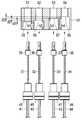
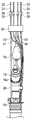
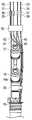
- FIG. 1is a front view showing the configuration of the endoscope
- FIG. 2is a side view showing the upper part of the operation unit
- FIG. 3is a view showing the configuration in the operation unit
- FIG. Itis sectional drawing which shows the structure of.
- the endoscope 1 of the present embodiment shown in FIGS. 1 and 2is an electronic endoscope, and an insertion portion 2 formed in a long and thin tubular shape, and an operation portion connected to a proximal end of the insertion portion 2
- a universal cord 4which is an endoscope cable extended from the operation unit 3 and an endoscope connector 5 disposed at the tip of the universal cord 4 are configured.
- the insertion portion 2 of the endoscope 1is formed of a flexible tubular member in which a distal end portion 6, a bending portion 7 and a flexible tube portion 8 are arranged in series from the distal end side.
- the illumination light transmitted by the light guide bundle and the imaging unit incorporating an objective optical system, an image sensor such as a CCD, a CMOS, etc.is irradiated in the distal end portion 6 of the insertion unit 2 or the operation unit 3.
- the bending portion 7 of the insertion portion 2is in the circumferential direction around the insertion axis O including the up-down / left-right direction (UP-DOWN / RIGHT-LEFT) according to the operation input by the user who is the operator to the operation portion 3 And is configured to be able to be actively curved.
- the flexible tube portion 8 of the insertion portion 2is constituted by a passively bendable flexible tubular member.
- An imaging cable, a light guide bundle, a treatment instrument insertion channel, and an air / water feeding tubeare inserted into the flexible tube portion 8 (all not shown).
- the operation portion 3 of the endoscope 1is provided on the base end side of the folding portion 11 and the folding portion 11 connected to the flexible tube portion 8 in a state of covering the base end of the flexible tube portion 8.
- An insertion portion rotary dial 12capable of adjusting the rotational position of the inserted insertion portion 2 around the insertion axis O, and a grip which can be gripped by the hand of the user etc. It comprises the part 13 and the operation part main body 14 continuously provided in the proximal end side of this holding part 13. As shown in FIG.
- the direction around the insertion axis O as the longitudinal axis in the operation unit 3is defined on the basis of a state in which the user or the like grips the grip unit 13.
- the operation unit 3In the figure, front and rear, right and left directions (front, back, left and right sides, etc.) are defined with reference to the user holding the grip 13 or the like.
- the gripping portion 13is formed in a symmetrical shape with respect to the insertion axis O, and a user or the like can similarly grip it with either the left hand or the right hand.
- a treatment tool insertion portion 15is provided on the front of the distal end side of the grip portion 13.
- the treatment tool insertion portion 15is configured to include a treatment tool insertion port 16 for inserting various treatment tools (not shown).
- a treatment tool insertion channelis in communication with the treatment tool insertion port 16 via a branching member (all not shown).
- a disposable forceps plug(not shown), which is a cover member for closing the treatment instrument insertion opening 16, is detachably attached to the treatment instrument insertion portion 15.
- the operation portion main body 14is constituted by a substantially partially spherical hollow member which is expanded mainly to the left and right sides and the front on the base end side of the grip portion 13.
- operation buttons 20 for executing the suction function of the endoscope 1, various optical system functions, and the likeare disposed.
- the operation buttons 20are, for example, disposable suction valves 22 detachably mounted on the operation unit main body 14 and an arbitrary function, for example, a release button, selected from various functions related to the endoscope 1. And two button switches 23 that can be assigned.
- the suction valve 22has a suction button 24 as an operation input member, and a tube connection portion 25 to which a suction tube extended from an endoscope suction unit as an external device (not shown) is connected. It is done.
- a universal cord 4is extended from one side (for example, the left side) of the operation unit main body 14 through a cable folding portion 17.
- a bending operation lever portion 30 as a bending operation member for performing a bending operation on the bending portion 7is disposed on the back side of the operation portion main body 14.
- the left and right shape of the operation portion main body 14is a bulging shape symmetrical with respect to the insertion axis O, and the left and right side surfaces of the distal end side of the operation portion main body 14
- a guide recess 18 for guiding a forefinger or the like of the user who grips the grip 13 to the operation buttons 20is formed.
- the universal cord 4extends from the distal end 6 to the operation unit 3 through the inside of the insertion unit 2 and further, various signal lines including an imaging cable extending from the operation unit 3, a light guide bundle, and a fluid for air and water flow It is a composite cable which the tube for air / water supply (all are not shown) penetrates inside.
- the endoscope connector 5 provided at the end of the universal cord 4has an electrical connector 5a provided on the side and a light source connector 5b connected to a light source device which is an external device (not shown). ing.
- a connector of a video processor which is an external device (not shown) or an extended electric cableis detachably connected to the electrical connector 5a. Further, the light source connector 5b is provided with a light guide connector 5c in which a light guide bundle is accommodated.
- a frame 26 and the likeare provided in the operation unit 3, and a pipe branch portion 16 a and the like connected to the treatment instrument insertion port 16 which is an internal object are fixed to the frame 26.
- the treatment instrument insertion port 16is in communication with the treatment instrument channel 19 via the duct branch portion 16a.
- the bending portion 7is actively bent in four directions of up, down, left, and right by being pulled and loosened according to the tilting operation of the bending operation lever portion 30 and has substantially the same length.
- four first to fourth bending operation wires 31, 32, 33, 34are disposed.
- first to fourth bending operation wiresare provided with turn buckles 35, 36, 37, 38 for adjusting the length at their respective midway portions, so as to tightly wind a metal wire etc.
- Each of the four first to fourth coil tubes 41, 42, 43, and 44 as tubular membersis inserted in a freely advancing and retracting manner.
- These four first to fourth coil tubes 41, 42, 43, 44have substantially the same length, and one end of the four coil tubes 41, 42, 43, 44 has one end fixed to the coil receiver 50 which is a tubular member fixing portion in the operation portion 3. , And is inserted in a bent state so as to avoid the duct branch part 16a and the like connected to the treatment instrument insertion port 16.
- One end of each of the four first to fourth coil tubes 41, 42, 43, and 44 as the tip end side (the insertion portion 2 side)is a cylindrical locked portion having an outward flange.
- First to fourth connection terminals 45, 46, 47, 48are provided.
- the coil receiver 50 as a tubular member fixing portionis fixed to the frame 26, and in this case, is a block formed of a rectangular metal, a hard resin or the like.
- the coil receiver 50locks the first to fourth connection terminals 45, 46, 47, 48 of the first to fourth coil tubes 41, 42, 43, 44, respectively.
- the first to fourth inward facing flanges 55, 56, 57, 58 to be fixedare formed, here having the four first to fourth locking portions 51, 52, 53, 54 as through holes. There is.
- the first to fourth locking portions 51, 52, 53, 54are not limited to the through holes, as long as they can lock the first to fourth connection terminals 45, 46, 47, 48. It may be a groove or the like.
- the first to fourth locking portions 51, 52, 53, 54 formed in the coil receiver 50 of the present embodimenthave the heights (depths) of the first to fourth inward flanges 55, 56, 57, 58. Each dimension is different.
- the first inward flange 55 of the first locking portion 51is formed to have the shortest length h 1 from the upper surface side of the coil receiver 50, and the first inward flange 55 of the second locking portion 52
- the second inward flange 56is formed so that the depth from the upper surface of the coil receiver 50 is then a short length h2.
- the third inward flange 57 of the third locking portion 53is then formed to have a length h3 which is shorter in depth from the upper surface of the coil receiver 50, and the inward flange 58 of the locking portion 54 is formed of the coil receiver 50.
- the depth from the upper surfaceis formed to be the longest length h4.
- the difference between the length h1 and the length h2is set to the length d1
- the difference between the length h2 and the length h3is set to the length d3
- the difference between the length h3 and the length h4is set to the length d3.
- the difference in height (depth) between the first inward flange 55 of the first locking portion 51 and the fourth inward flange 58 of the fourth locking portion 54is the largest, and the difference is long
- the sum of d1, d2 and d3is (d1 + d2 + d3).
- the depth dimensions of the first to fourth inward flanges 55, 56, 57, 58 formed in the first to fourth locking portions 51, 52, 53, 54are the first to fourth coils. It is set in order to suppress the difference in the amount of bending when the tubes 41, 42, 43, 44 are disposed avoiding the pipeline branch portion 16a of the built-in which becomes an obstacle.
- the first coil tube 41is locked to the coil receiver 50 at the farthest position in order to avoid the duct branch portion 16a and the like.
- the 2nd coil tube 42 and the 3rd coil tube 43are latched by coil receptacle 50 in a distant position in order, and the 4th coil tube 44 is latched by coil receptacle 50 in the nearest position.
- the first inward flange 55 of the first locking portion 51 for locking the first connection terminal 45 of the first coil tube 41is made shallowest, and the second connection terminal of the second coil tube 42 is made 46, the second inward flange 56 of the second locking portion 52 for locking, and the third inward flange of the third locking portion 53 for locking the third connection terminal 47 of the third coil tube 43 57 is made deeper sequentially, and the fourth inward flange 58 for locking the fourth connection terminal 48 is made the deepest.
- the coil receiver 50optimizes the position where the end portions of the first to fourth coil tubes 41, 42, 43, 44 disposed with different deflection amounts are locked and fixed.
- the lengths of the first to fourth coil tubes 41, 42, 43, 44are substantially the same, and the lengths of the first to fourth bending operation wires 31, 32, 33, 34 are also Since it is substantially the same, if the locking position in the coil receiver 50 is the same position in the direction orthogonal to the insertion axis O, the amount of bending of the fourth coil tube 44 locked to the coil receiver 50 at the closest position is In many cases, the amount of deflection decreases toward the first coil tube 41 locked to the coil receiver 50 at the farthest position. As described above, when the bending amounts of the first to fourth coil tubes 41, 42, 43, 44 are largely different, the tensions of the first to fourth bending operation wires 31, 32, 33, 34 vary.
- the bending amounts of the first to fourth coil tubes 41, 42, 43, 44are optimized by the coil receiver 50, and the first to fourth bending operation wires 31, 32, Variations in tension of 33 and 34 are suppressed.
- the coil receivers 50are arranged in parallel at different positions along the longitudinal axis in the direction perpendicular to the insertion axis O, here, the longitudinal axis of the operation unit 3.
- the deflection amounts of the first to fourth coil tubes 41, 42, 43 and 44are optimized.
- the endoscope 1 of the present embodimentsuppresses the variation in the amount of pulling force of the first to fourth bending operation wires 31, 32, 33, 34 for bending the bending portion 7 of the insertion portion 2
- the bending angle of the bending portion 7 corresponding to the operation amount of the bending operation lever portion 30can be made substantially uniform.
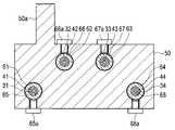
- FIG. 5is a view showing the configuration in the operation unit of the first modification
- FIG. 6is a cross-sectional view taken along the line VI-VI of FIG. 5 according to the first modification.
- the coil receiver 50 of the endoscope 1 of the present modificationis provided with four first to fourth through holes 61, 62, 63, 64 as locking portions. ing.
- the four first to fourth coil tubes 41, 42, 43, and 44 of this modificationhave cylindrical shapes that become locked portions at one end portions that become the respective distal end sides (the insertion portion 2 side).
- Four first to fourth anchors 65, 66, 67, 68are provided.
- the coil receiver 50is provided with a projection 50a for fixing the frame 26 with a fixing member such as a screw (see FIG. 6).
- the first to fourth anchors 65, 66, 67, 68are inserted through the first to fourth through holes 61, 62, 63, 64 of the coil receiver 50, and then fixed screws 65a, 66a,
- the coil receiver 50is configured to be fixed to the coil receiver 50 from the side circumferential direction by 67a and 68a.
- the coil receiver 50communicates with the four first to fourth through holes 61, 62, 63, 64 on the side surface, and is provided with screw holes into which the fixing screws 65a, 66a, 67a, 68a are screwed. .
- the fixing positions of the first to fourth anchors 65, 66, 67, 68 in the axial direction of the first to fourth through holes 61, 62, 63, 64 of the coil receiver 50.Can be adjusted, and the deflection amounts of the first to fourth coil tubes 41, 42, 43 and 44 can be further optimized.
- the coil receivers 50are arranged in parallel at different positions along the longitudinal axis in the direction orthogonal to the insertion axis O, here the longitudinal axis of the operation unit 3. , 42, 43, 44, the deflection amounts of the first to fourth coil tubes 41, 42, 43, 44 are optimized.
- the variation in the amount of pulling force of the first to fourth bending operation wires 31, 32, 33, 34 for curving the bending portion 7 of the insertion portion 2is further suppressed.
- the bending angle of the bending portion 7 according to the amount of operation of the bending operation lever portion 30can be made substantially even.
- FIG. 7is a diagram showing the configuration in the operation unit of the second modified example.
- the coil receiver 50 in the endoscope 1 of the present modificationis rotatably provided around the shaft 72 of the fixing screw 71 serving as a rotating shaft, and is desired by tightening the fixing screw 71. It can be fixed at the pivot position of The coil receiver 50 is fixed by screwing the fixing screw 71 to a projection (not shown) of the frame 26.
- first to fourth locking portions 51, 52, 53, 54 formed on the coil receiver 50are the first to fourth inward flanges 55, 56, 57, 58 from the upper surface side of the coil receiver 50.
- the height (depth) dimensions ofare all formed with the same length.
- the coil receiver 50has a height substantially the same as the length of the first to fourth connection terminals 45, 46, 47, 48.
- the coil support 50is rotated at a position where the amount of deflection of each of the first to fourth coil tubes 41, 42, 43, 44 is optimized, and fixed by the fixing screw 71.
- the amount of deflection of each of the first to fourth coil tubes 41, 42, 43, 44can be further optimized.
- the coil receivers 50are arranged in parallel at different positions along the longitudinal axis in the direction orthogonal to the insertion axis O, here the longitudinal axis of the operation unit 3. , 42, 43, 44, the deflection amounts of the first to fourth coil tubes 41, 42, 43, 44 are optimized.
- the endoscope 1 of the present modificationit is possible to suppress the variation in the amount of pulling force of the first to fourth bending operation wires 31, 32, 33, 34 for bending the bending portion 7 of the insertion portion 2
- the bending angle of the bending portion 7 corresponding to the operation amount of the bending operation lever portion 30can be made substantially uniform.
- the axis 72 of the fixing screw 71 serving as the rotation axismay not be at the center of the coil receiver 50, and the position of the rotation axis may be anywhere.
- FIG. 8is a diagram showing the configuration in the operation unit of the third modified example. As shown in FIG. 8, in the case of a hybrid scope in which the endoscope 1 has an imaging unit 75 which is an internal component provided with a CCD or a CMOS in the operation unit 3, the imaging unit 75 is an obstacle.
- the coil receiver 50 of the above-described embodiment or modificationcan be obtained.
- the configurationsuppresses the difference in deflection amount.
- FIG. 9is a diagram showing the configuration in the operation unit of the fourth modification. As shown in FIG. 9, when the endoscope 1 has a balloon water injection port 77 which is a built-in product for injecting water to the balloon in the operation unit 3, the balloon water injection port 77 becomes an obstacle.
- the coil receiver 50 of the above-described embodiment or modificationmay be used.
- the difference in the amount of deflectionis suppressed by the configuration of.
- FIG. 10is a diagram showing the configuration in the operation unit of the fifth modification.
- the first to fourth coil tubes 41, 42, 43, 44are illustrated as having a configuration in which the first to fourth coil tubes 41, 42, 43 are inserted avoiding only one side such as the channel branch 16a connected to the treatment instrument insertion port 16
- the first and second coil tubes 41 and 42 and the third and fourth coil tubes 43 and 44are divided and inserted so as to avoid both sides of the obstacle. You may
- the first and fourth inward flanges 55 and 58 in the first to fourth locking portions 51, 52, 53, 54are formed deep, and the second and third inward The flanges 56, 57 are formed shallow.
- the first to fourth locking portions 51, 52formed in the coil receiver 50.
- the depth dimensions of the first to fourth inward flanges 55, 56, 57, 58 of H. 53, 54may be set as appropriate.
- the bending operation lever unit 30as the joystick type bending operation member is illustrated in the embodiment and the modification described above, the bending operation member such as a lever type or a knob type is not limited thereto. It is the structure applicable also to the endoscope 1 which it had.
- the invention described in the above embodimentis not limited to those embodiments, and various modifications can be made without departing from the scope of the invention in the implementation stage.
- the above embodimentsinclude inventions of various stages, and various inventions can be extracted by an appropriate combination of a plurality of disclosed configuration requirements. For example, even if some of the configuration requirements are removed from all the configuration requirements shown in each form, the configuration requirements can be eliminated if the problems described can be solved and the described advantages can be obtained.
- the configurationcan be extracted as the invention.
- an endoscopewhich suppresses variation in the amount of pulling force of a plurality of bending operation wires for bending the bending portion, and makes the bending angle of the bending portion substantially uniform according to the operation amount of the bending operation portion. it can.
Landscapes
- Health & Medical Sciences (AREA)
- Life Sciences & Earth Sciences (AREA)
- Surgery (AREA)
- Physics & Mathematics (AREA)
- Engineering & Computer Science (AREA)
- Optics & Photonics (AREA)
- Biomedical Technology (AREA)
- General Health & Medical Sciences (AREA)
- Pathology (AREA)
- Nuclear Medicine, Radiotherapy & Molecular Imaging (AREA)
- Biophysics (AREA)
- Heart & Thoracic Surgery (AREA)
- Medical Informatics (AREA)
- Molecular Biology (AREA)
- Animal Behavior & Ethology (AREA)
- Radiology & Medical Imaging (AREA)
- Public Health (AREA)
- Veterinary Medicine (AREA)
- Multimedia (AREA)
- Astronomy & Astrophysics (AREA)
- General Physics & Mathematics (AREA)
- Instruments For Viewing The Inside Of Hollow Bodies (AREA)
- Endoscopes (AREA)
Abstract
Description
Translated fromJapanese本発明は、湾曲部を複数の湾曲操作ワイヤで湾曲操作する内視鏡に関する。The present invention relates to an endoscope which bends a bending portion with a plurality of bending operation wires.
従来、生体の体内、構造物の内部など、観察が困難な被検体の内部の箇所を観察するために、被検体内に挿入可能な内視鏡が、例えば、医療分野または工業分野において広く利用されている。Conventionally, an endoscope which can be inserted into a subject is widely used, for example, in the medical field or the industrial field, in order to observe a location inside a subject that is difficult to observe, such as the inside of a living body or the inside of a structure. It is done.
このような内視鏡の挿入部には、被検体内の挿入性及び観察性を向上させるための湾曲部が設けられている。この湾曲部は、操作部の上部側に設けられた湾曲操作部により湾曲操作される。The insertion portion of such an endoscope is provided with a curved portion for improving the insertability and the observability in the subject. The bending portion is bent by a bending operation portion provided on the upper side of the operation portion.
例えば、国際公開WO2011-052372号公報に開示されるように、湾曲操作部としてレバー型の湾曲操作レバーの回動操作によって複数の湾曲操作ワイヤを牽引弛緩することで湾曲部を湾曲操作する内視鏡が知られている。For example, as disclosed in International Publication WO 2011-052372, an endoscope which bends a bending portion by pulling and loosening a plurality of bending operation wires by turning the bending operation lever as a bending operation portion. The mirror is known.
ところで、従来の内視鏡は、湾曲部を湾曲操作する複数の湾曲操作ワイヤを操作部の内蔵物を避けて挿通する必要がある。そのため、複数の湾曲操作ワイヤは、操作部内で直線状とならず、内蔵物を避けるために撓んだ状態で挿通されている。By the way, in the conventional endoscope, it is necessary to insert a plurality of bending operation wires for bending the bending portion while avoiding the built-in parts of the operation portion. Therefore, the plurality of bending operation wires are not linear in the operation unit, and are inserted in a bent state to avoid the built-in components.
これにより、複数の湾曲操作ワイヤの撓み量が異なり、湾曲部を湾曲する際の湾曲操作ワイヤのテンションがばらつき、牽引力量が湾曲操作ワイヤ毎に異なってしまうという問題がある。そのため、湾曲操作部の操作量に応じた湾曲部の湾曲角度にばらつきが生じるという課題があった。As a result, the bending amounts of the plurality of bending operation wires are different, the tension of the bending operation wire varies when bending the bending portion, and the amount of pulling force is different for each bending operation wire. Therefore, there has been a problem that the bending angle of the bending portion varies in accordance with the operation amount of the bending operation portion.
そこで、本発明は上記事情に鑑みてなされたものであり、湾曲部を湾曲操作する複数の湾曲操作ワイヤの牽引力量のばらつきを抑制し、湾曲操作部の操作量に応じた湾曲部の湾曲角度を略均一にする内視鏡を提供することを目的としている。Then, this invention is made in view of the said situation, suppresses the dispersion | variation in the amount of pulling force of the some bending operation wire which carries out bending operation of a bending part, and the bending angle of the bending part according to the operation amount of the bending operation part It is an object of the present invention to provide an endoscope that makes the
本発明の一態様における内視鏡は、操作部に設けられ、挿入部の湾曲部を湾曲操作する湾曲操作部材と、前記湾曲操作部材によって牽引弛緩される複数の湾曲操作ワイヤと、前記操作部内に設けられ、前記複数の湾曲操作ワイヤがそれぞれ挿通し、前記操作部内に設けられた内蔵物を避けるように撓んだ状態で配設された複数の管状部材と、前記操作部内に設けられ、前記複数の管状部材の端部を前記操作部の長手軸に直交する方向における前記長手軸に沿った異なる位置で固定して前記複数の管状部材の撓みを最適化する管状部材固定部と、を具備する。The endoscope according to one aspect of the present invention is provided in the operation unit, and a bending operation member that bends and operates the bending portion of the insertion unit, a plurality of bending operation wires to be pulled and relaxed by the bending operation member, and the inside of the operation unit A plurality of tubular members provided in each of the plurality of tubular members, the plurality of bending operation wires being respectively inserted, and disposed in a bent state so as to avoid built-in objects provided in the operation unit; A tubular member fixing portion for fixing the ends of the plurality of tubular members at different positions along the longitudinal axis in the direction orthogonal to the longitudinal axis of the operation portion to optimize the deflection of the plurality of tubular members; Prepare.
以下に、本発明の好ましい形態について図面を参照して説明する。
なお、以下の説明に用いる図においては、各構成要素を図面上で認識可能な程度の大きさとするため、構成要素毎に縮尺を異ならせてあるものであり、本発明は、これらの図に記載された構成要素の数量、構成要素の形状、構成要素の大きさの比率、および各構成要素の相対的な位置関係のみに限定されるものではない。また、以下の説明においては、図の紙面に向かって見た上下方向を構成要素の上部および下部として説明している場合がある。
図1は、内視鏡の構成を示す正面図、図2は操作部の上部分を示す側面図、図3は操作部内の構成を示す図、図4はコイルチューブが係止されるコイル受の構成を示す断面図である。Hereinafter, preferred embodiments of the present invention will be described with reference to the drawings.
In the drawings used for the following description, in order to make each component a size that can be recognized in the drawings, the scale is different for each component, and the present invention It is not limited only to the number of components described, the shape of the components, the ratio of the sizes of the components, and the relative positional relationship between the components. Further, in the following description, the upper and lower directions viewed in the plane of the drawing may be described as the upper part and the lower part of the component.
1 is a front view showing the configuration of the endoscope, FIG. 2 is a side view showing the upper part of the operation unit, FIG. 3 is a view showing the configuration in the operation unit, and FIG. It is sectional drawing which shows the structure of.
先ず、本実施の形態の内視鏡について以下に説明する。
図1および図2に示す本実施形態の内視鏡1は、電子内視鏡であって、細長管状に形成された挿入部2と、この挿入部2の基端に連設された操作部3と、この操作部3から延設された内視鏡ケーブルであるユニバーサルコード4と、このユニバーサルコード4の先端に配設された内視鏡コネクタ5と、を備えて構成されている。First, an endoscope according to the present embodiment will be described below.
The
内視鏡1の挿入部2は、先端側から順に、先端部6、湾曲部7および可撓管部8が連設された可撓性を有する管状部材によって構成されている。The
挿入部2の先端部6または操作部3内には、ここでは図示しないが、対物光学系、CCD、CMOSなどのイメージセンサなどを内蔵した撮像ユニット、ライトガイドバンドルによって伝送された照明光を照射する照明光学系、処置具チャンネルを接続保持するチャンネルパイプなどが配設されている。Although not illustrated here, the illumination light transmitted by the light guide bundle and the imaging unit incorporating an objective optical system, an image sensor such as a CCD, a CMOS, etc. is irradiated in the
挿入部2の湾曲部7は、操作部3に対する術者である使用者などの操作入力に応じて、上下左右方向(UP-DOWN/RIGHT-LEFT)を含む挿入軸O周りの全周方向へと能動的に湾曲させ得るように構成されている。The
挿入部2の可撓管部8は、受動的に湾曲可能な可撓性を有する管状部材によって構成されている。この可撓管部8の内部には、撮像ケーブル、ライトガイドバンドル、処置具挿通チャンネルおよび送気送水用チューブが挿通されている(何れも不図示)。The flexible tube portion 8 of the
内視鏡1の操作部3は、可撓管部8の基端を覆った状態にて可撓管部8に接続された折止部11と、この折止部11の基端側に設けられた挿入部2の挿入軸O回りの回転位置を調整自在に行える挿入部回転ダイヤル12と、この挿入部回転ダイヤル12の基端側に連設され、使用者などの手によって把持可能な把持部13と、この把持部13の基端側に連設された操作部本体14と、を有して構成されている。The
なお、本実施形態において、操作部3における長手軸としての挿入軸O周りの方向などは使用者などが把持部13を把持した状態を基準として定義されており、具体的には、操作部3には、把持部13を把持した使用者などを基準とする前後左右方向(正面、背面および左右側面など)が定義されている。In the present embodiment, the direction around the insertion axis O as the longitudinal axis in the
把持部13は、挿入軸Oに対して左右対称な形状に形成され、使用者などが左手または右手の何れの手によっても同様に把持することが可能となっている。The gripping
この把持部13の先端側の正面には、処置具挿通部15が設けられている。この処置具挿通部15は、図示しない各種の処置具を挿入する処置具挿通口16を備えて構成されている。A treatment
操作部3の内部において、処置具挿通口16には、分岐部材を介して、処置具挿通チャンネルが連通されている(何れも不図示)。また、処置具挿通部15には、処置具挿通口16を閉塞するための蓋部材である図示しない例えば、ディスポーザブルの鉗子栓が着脱自在となっている。Inside the
操作部本体14は、把持部13の基端側において、主として左右側方および前方に膨出された略部分球状を成す中空部材によって構成されている。この操作部本体14の正面側には、内視鏡1の吸引機能、各種光学系機能などを実行するための操作ボタン類20が配設されている。The operation portion
これら操作ボタン類20は、例えば、操作部本体14に着脱自在に装着された例えば、ディスポーザブルの吸引バルブ22と、内視鏡1に関する各種機能の中から任意の機能、例えば、レリーズボタンなどを選択的に割り当てることが可能な2つのボタンスイッチ23と、を有して構成されている。The
なお、吸引バルブ22は、操作入力部材としての吸引ボタン24と、図示しない外部機器である内視鏡吸引器から延設された吸引チューブが接続されるチューブ接続部25と、を有して構成されている。The
操作部本体14の一側部(例えば、左側部)からは、ケーブル折止部17を介して、ユニバーサルコード4が延出されている。A
操作部本体14の背面側には、図2に示すように、湾曲部7に対する湾曲操作を行うための湾曲操作部材としての湾曲操作レバー部30が配設されている。As shown in FIG. 2, a bending
ここで、図1に示したように、操作部本体14の左右形状は、挿入軸Oに対して左右対称な膨出形状となっており、この操作部本体14の先端側の左右側面には、把持部13を把持した使用者などの人差し指などを操作ボタン類20に導くガイド用凹部18がそれぞれ形成されている。Here, as shown in FIG. 1, the left and right shape of the operation portion
ユニバーサルコード4は、挿入部2の内部を通じて先端部6側から操作部3に至り、さらに操作部3から延出する撮像ケーブルを含む各種信号線、ライトガイドバンドルおよび送気送水用の流体が流入される送気送水用チューブ(いずれも不図示)が内部に挿通する複合ケーブルである。The
ユニバーサルコード4の端部に設けられた内視鏡コネクタ5は、側面部に設けられた電気コネクタ部5aと、図示しない外部機器である光源装置と接続される光源コネクタ部5bと、を有している。The endoscope connector 5 provided at the end of the
なお、電気コネクタ部5aには、図示しない外部機器であるビデオプロセッサか延設された電気ケーブルのコネクタが着脱自在に接続される。また、光源コネクタ部5bには、ライトガイドバンドルが収容されたライトガイドコネクタ部5cが配設されている。A connector of a video processor which is an external device (not shown) or an extended electric cable is detachably connected to the
図3に示すように、操作部3内には、フレーム26などが設けられ、このフレーム26に内蔵物となる処置具挿通口16と接続された管路分岐部16aなどが固定されている。そして、処置具挿通口16は、管路分岐部16aを介して処置具チャンネル19に連通している。As shown in FIG. 3, a
また、操作部3内には、湾曲操作レバー部30の傾倒操作に応じて、牽引弛緩されることで湾曲部7を上下左右の4方向に能動的に湾曲させ、略同一の長さを有する、ここでは4本の第1~第4の湾曲操作ワイヤ31,32,33,34が配設されている。Further, in the
これら4本の第1~第4の湾曲操作ワイヤは、それぞれの中途部分に長さ調整のためのターンバックル35,36,37,38が介装されており、金属素線などを密巻きにした管状部材としての4本の第1~第4のコイルチューブ41,42,43,44に、それぞれが進退自在に挿通されている。These four first to fourth bending operation wires are provided with
これら4本の第1~第4のコイルチューブ41,42,43,44は、略同一の長さを有し、操作部3内において、管状部材固定部であるコイル受50に一端が固定保持され、処置具挿通口16と接続された管路分岐部16aなどを避けるように撓んだ状態で挿通している。These four first to
これら4本の第1~第4のコイルチューブ41,42,43,44のそれぞれの先端側(挿入部2側)となる一端部には、外向フランジを有する筒状の被係止部としての第1~第4の接続ターミナル45,46,47,48が配設されている。One end of each of the four first to
管状部材固定部としてのコイル受50は、フレーム26に固定され、ここでは矩形状の金属、硬質樹脂などから形成されたブロック体である。The
このコイル受50は、図4に示すように、第1~第4のコイルチューブ41,42,43,44の第1~第4の接続ターミナル45,46,47,48をそれぞれ係止して固定する第1~第4の内向フランジ55,56,57,58が形成された、ここでは貫通孔としての4つの第1~第4の係止部51,52,53,54を有している。As shown in FIG. 4, the
なお、第1~第4の係止部51,52,53,54は、貫通孔に限定されることなく、第1~第4の接続ターミナル45,46,47,48を係止できればよく、溝部などでもよい。The first to
本実施の形態のコイル受50に形成された第1~第4の係止部51,52,53,54は、第1~第4の内向フランジ55,56,57,58の高さ(深さ)寸法がそれぞれ異なっている。The first to
具体的には、第1の係止部51の第1の内向フランジ55は、コイル受50の上面側からの深さが最も短い長さh1に形成され、第2の係止部52の第2の内向フランジ56はコイル受50の上面からの深さが次いで短い長さh2に形成されている。Specifically, the first
そして、第3の係止部53の第3の内向フランジ57は、コイル受50の上面からの深さが次いで短い長さh3に形成され、係止部54の内向フランジ58はコイル受50の上面からの深さが最も長い長さh4に形成されている。The third
また、長さh1と長さh2の差が長さd1、長さh2と長さh3の差が長さd3および長さh3と長さh4の差が長さd3に設定されている。The difference between the length h1 and the length h2 is set to the length d1, the difference between the length h2 and the length h3 is set to the length d3, and the difference between the length h3 and the length h4 is set to the length d3.
即ち、第1の係止部51の第1の内向フランジ55と、第4の係止部54の第4の内向フランジ58の高さ(深さ)の差は、最も大きく、その差は長さd1,d2,d3の合計(d1+d2+d3)となっている。That is, the difference in height (depth) between the first
これら、第1~第4の係止部51,52,53,54に形成される第1~第4の内向フランジ55,56,57,58の深さ寸法は、第1~第4のコイルチューブ41,42,43,44が障害物となる内蔵物の管路分岐部16aなどを避けて配設される際の撓み量の違いを抑制するために設定されている。The depth dimensions of the first to fourth
即ち、ここでは、管路分岐部16aなどを避けるため、第1のコイルチューブ41が最も遠い位置でコイル受50に係止される。そして、第2のコイルチューブ42、第3のコイルチューブ43は、順に遠い位置でコイル受50に係止されており、第4のコイルチューブ44が最も近い位置でコイル受50に係止されている。That is, in this case, the
そのため、第1のコイルチューブ41の第1の接続ターミナル45を係止する第1の係止部51の第1の内向フランジ55を最も浅くし、第2のコイルチューブ42の第2の接続ターミナル46を係止する第2の係止部52の第2の内向フランジ56、第3のコイルチューブ43の第3の接続ターミナル47を係止する第3の係止部53の第3の内向フランジ57を順に深くして、第4の接続ターミナル48を係止する第4の内向フランジ58を最も深くしている。Therefore, the first
このように、本実施の形態では、異なる撓み量で配設される第1~第4のコイルチューブ41,42,43,44の端部を係止して固定する位置をコイル受50で最適化することができる。As described above, in the present embodiment, the
即ち、第1~第4のコイルチューブ41,42,43,44は、それぞれの長さが略同じであり、第1~第4の湾曲操作ワイヤ31,32,33,34のそれぞれの長さも略同じであるため、コイル受50における係止位置が挿入軸Oに直交する方向の同じ位置であると、最も近い位置でコイル受50に係止される第4のコイルチューブ44の撓み量が多く、最も遠い位置でコイル受50に係止される第1のコイルチューブ41に向けて撓み量が少なくなる。このように、第1~第4のコイルチューブ41,42,43,44の撓み量が大きく異なってしまうと、第1~第4の湾曲操作ワイヤ31,32,33,34のテンションがばらつく。That is, the lengths of the first to
そのため、本実施の形態では、第1~第4のコイルチューブ41,42,43,44のそれぞれの撓み量をコイル受50によって最適化して、第1~第4の湾曲操作ワイヤ31,32,33,34のテンションのばらつきを抑えるようにしている。Therefore, in the present embodiment, the bending amounts of the first to
即ち、コイル受50は、挿入軸O、ここでは操作部3の長手軸に直交する方向における長手軸に沿った異なる位置に並設するように、第1~第4のコイルチューブ41,42,43,44の先端を係止することで、第1~第4のコイルチューブ41,42,43,44のそれぞれの撓み量を最適化している。That is, the
これにより、湾曲操作部材である湾曲操作レバー部30の操作量(傾倒量)に応じた湾曲部7を能動的に湾曲するための第1~第4の湾曲操作ワイヤ31,32,33,34の牽引力量が同等となり、湾曲操作レバー部30の操作量(傾倒量)に応じた湾曲部7の湾曲角度にばらつきが生じることを防止することができる。Thereby, the first to fourth
以上の説明から、本実施の形態の内視鏡1は、挿入部2の湾曲部7を湾曲操作する第1~第4の湾曲操作ワイヤ31,32,33,34の牽引力量のばらつきを抑制して、湾曲操作レバー部30の操作量に応じた湾曲部7の湾曲角度を略均一にすることができるようになる。From the above description, the
(第1の変形例)
図5は、第1の変形例の操作部内の構成を示す図、図6は第1の変形例に係り、図5のVI-VI線断面図である。
図5および図6に示すように、本変形例の内視鏡1におけるコイル受50には、係止部となる4つの第1~第4の貫通孔61,62,63,64が設けられている。また、本変形例の4本の第1~第4のコイルチューブ41,42,43,44は、それぞれの先端側(挿入部2側)となる一端部に被係止部となる筒状の4つの第1~第4のアンカ65,66,67,68が設けられている。なお、コイル受50は、フレーム26にビスなどの固定部材で固定するための凸部50aが設けられている(図6参照)。(First modification)
FIG. 5 is a view showing the configuration in the operation unit of the first modification, and FIG. 6 is a cross-sectional view taken along the line VI-VI of FIG. 5 according to the first modification.
As shown in FIGS. 5 and 6, the
第1~第4のアンカ65,66,67,68は、コイル受50の第1~第4の貫通孔61,62,63,64に挿通配置された後、それぞれが固定ビス65a,66a,67a,68aによって、側周部方向からコイル受50に固定されるように構成されている。なお、コイル受50は、側面に4つの第1~第4の貫通孔61,62,63,64に連通し、固定ビス65a,66a,67a,68aが螺合するビス孔が設けられている。The first to
このような構成とすることで、コイル受50の第1~第4の貫通孔61,62,63,64の孔軸方向に第1~第4のアンカ65,66,67,68の固定位置を調整することができ、第1~第4のコイルチューブ41,42,43,44のそれぞれの撓み量をより最適化することができるようになる。With such a configuration, the fixing positions of the first to
即ち、ここでも、コイル受50は、挿入軸O、ここでは操作部3の長手軸に直交する方向における長手軸に沿った異なる位置に並設するように、第1~第4のコイルチューブ41,42,43,44の先端を係止することで、第1~第4のコイルチューブ41,42,43,44のそれぞれの撓み量を最適化している。That is, also here, the
そのため、本変形例の内視鏡1は、挿入部2の湾曲部7を湾曲操作する第1~第4の湾曲操作ワイヤ31,32,33,34の牽引力量のばらつきを、より抑制することができ、湾曲操作レバー部30の操作量に応じた湾曲部7の湾曲角度をより略均一にすることができるようになる。Therefore, in the
(第2の変形例)
図7は、第2の変形例の操作部内の構成を示す図である。
図7に示すように、本変形の内視鏡1におけるコイル受50は、回動軸となる固定ビス71の軸72回りに回動自在に設けられており、固定ビス71の締め付けにより、所望の回動位置で固定できるようになっている。なお、コイル受50は、フレーム26の図示しない突起部に固定ビス71が螺着して固定される。(Second modification)
FIG. 7 is a diagram showing the configuration in the operation unit of the second modified example.
As shown in FIG. 7, the
また、コイル受50に形成される第1~第4の係止部51,52,53,54は、コイル受50の上面側からの第1~第4の内向フランジ55,56,57,58の高さ(深さ)寸法が全て同じ長さで形成されている。なお、ここでのコイル受50は、第1~第4の接続ターミナル45,46,47,48の長さと略同じ高さを有している。Further, the first to
このような構成とすることで、第1~第4のコイルチューブ41,42,43,44のそれぞれの撓み量が最適化する位置にコイル受50を回動して固定ビス71により固定することで、第1~第4のコイルチューブ41,42,43,44のそれぞれの撓み量をより最適化することができる。By adopting such a configuration, the
即ち、ここでも、コイル受50は、挿入軸O、ここでは操作部3の長手軸に直交する方向における長手軸に沿った異なる位置に並設するように、第1~第4のコイルチューブ41,42,43,44の先端を係止することで、第1~第4のコイルチューブ41,42,43,44のそれぞれの撓み量を最適化している。That is, also here, the
そのため、本変形例の内視鏡1においても、挿入部2の湾曲部7を湾曲操作する第1~第4の湾曲操作ワイヤ31,32,33,34の牽引力量のばらつきを抑制することができ、湾曲操作レバー部30の操作量に応じた湾曲部7の湾曲角度を略均一にすることができるようになる。なお、回動軸となる固定ビス71の軸72は、コイル受50中心でなくともよく、その回動軸の位置はどこにあってもよい。Therefore, also in the
(第3の変形例)
図8は、第3の変形例の操作部内の構成を示す図である。
図8に示すように、内視鏡1は、操作部3内にCCDまたはCMOSを備えた内蔵物である撮像ユニット75があるハイブリッドスコープの場合、この撮像ユニット75が障害物となる。(Third modification)
FIG. 8 is a diagram showing the configuration in the operation unit of the third modified example.
As shown in FIG. 8, in the case of a hybrid scope in which the
そのため、第1~第4のコイルチューブ41,42,43,44は、障害物となる撮像ユニット75を避けて配設される場合においても、上述の実施の形態または変形例のコイル受50の構成によって撓み量の違いが抑制される。Therefore, even in the case where the first to
(第4の変形例)
図9は、第4の変形例の操作部内の構成を示す図である。
図9に示すように、内視鏡1は、操作部3内にバルーンに注水する内蔵物であるバルーン注水口77がある場合、このバルーン注水口77が障害物となる。(The 4th modification)
FIG. 9 is a diagram showing the configuration in the operation unit of the fourth modification.
As shown in FIG. 9, when the
そのため、第1~第4のコイルチューブ41,42,43,44は、障害物となるバルーン注水口77を避けて配設される場合においても、上述の実施の形態または変形例のコイル受50の構成によって撓み量の違いが抑制される。Therefore, even when the first to
なお、操作部3内の内蔵物としては、そのほかに、図示しない送気送水管路口、スイッチなどが障害物となるが、第1~第4のコイルチューブ41,42,43,44は、これら障害物を避けて配設される場合においても、上述の実施の形態または変形例のコイル受50の構成によって撓み量の違いが抑制されるものである。In addition, as built-in items in the
(第5の変形例)
図10は、第5の変形例の操作部内の構成を示す図である。
上述では、第1~第4のコイルチューブ41,42,43,44が障害物である処置具挿通口16と接続された管路分岐部16aなどの片側のみに避けて挿通する構成を例示したが、図10に示すように、例えば、第1、第2のコイルチューブ41,42と、第3、第4のコイルチューブ43,44と、を分けて障害物の両脇を避けるように挿通させてもよい。(Fifth modification)
FIG. 10 is a diagram showing the configuration in the operation unit of the fifth modification.
In the above description, the first to
このような場合、コイル受50は、第1~第4の係止部51,52,53,54における第1、第4の内向フランジ55,58が深く形成され、第2、第3の内向フランジ56,57が浅く形成される。In such a case, in the
このように、第1~第4のコイルチューブ41,42,43,44が障害物を避けて挿通する構成に応じて、コイル受50に形成する第1~第4の係止部51,52,53,54の第1~第4の内向フランジ55,56,57,58のそれぞれの深さ寸法を適宜設定すればよい。Thus, according to the configuration in which the first to
なお、上述の実施の形態および変形例では、ジョイスティックタイプの湾曲操作部材としての湾曲操作レバー部30を例示しているが、これに限定されることなく、レバータイプ、ノブタイプなどの湾曲操作部材を有した内視鏡1にも適用可能な構成である。Although the bending
以上の実施の形態に記載した発明は、それらの形態に限ることなく、その他、実施段階ではその要旨を逸脱しない範囲で種々の変形を実施し得ることが可能である。さらに、上記各形態には、種々の段階の発明が含まれており、開示される複数の構成要件における適宜な組合せにより種々の発明が抽出され得るものである。
例えば、各形態に示される全構成要件から幾つかの構成要件が削除されても、述べられている課題が解決でき、述べられている効果が得られる場合には、この構成要件が削除された構成が発明として抽出され得るものである。The invention described in the above embodiment is not limited to those embodiments, and various modifications can be made without departing from the scope of the invention in the implementation stage. Furthermore, the above embodiments include inventions of various stages, and various inventions can be extracted by an appropriate combination of a plurality of disclosed configuration requirements.
For example, even if some of the configuration requirements are removed from all the configuration requirements shown in each form, the configuration requirements can be eliminated if the problems described can be solved and the described advantages can be obtained. The configuration can be extracted as the invention.
本発明によれば、湾曲部を湾曲操作する複数の湾曲操作ワイヤの牽引力量のばらつきを抑制し、湾曲操作部の操作量に応じた湾曲部の湾曲角度を略均一にする内視鏡を実現できる。According to the present invention, an endoscope is realized which suppresses variation in the amount of pulling force of a plurality of bending operation wires for bending the bending portion, and makes the bending angle of the bending portion substantially uniform according to the operation amount of the bending operation portion. it can.
本出願は、2017年10月2日に日本国に出願された特願2017-192782号を優先権主張の基礎として出願するものであり、上記の開示内容は、本願明細書、請求の範囲に引用されるものとする。This application is based on Japanese Patent Application No. 2017-192782, filed on Oct. 2, 2017, as the basis for claiming priority, and the above disclosure is hereby incorporated by reference into the present specification and claims. It shall be quoted.
Claims (6)
Translated fromJapanese前記湾曲操作部材によって牽引弛緩される複数の湾曲操作ワイヤと、
前記操作部内に設けられ、前記複数の湾曲操作ワイヤがそれぞれ挿通し、前記操作部内に設けられた内蔵物を避けるように撓んだ状態で配設された複数の管状部材と、
前記操作部内に設けられ、前記複数の管状部材の端部を前記操作部の長手軸に直交する方向における前記長手軸に沿った異なる位置で固定して前記複数の管状部材の撓みを最適化する管状部材固定部と、
を具備することを特徴とする内視鏡。A bending operation member provided in the operation unit for bending the bending portion of the insertion portion;
A plurality of bending operation wires pulled and relaxed by the bending operation member;
A plurality of tubular members provided in the operation unit, the plurality of bending operation wires being respectively inserted, and disposed in a bent state so as to avoid a built-in object provided in the operation unit;
Fixing the ends of the plurality of tubular members at different positions along the longitudinal axis in a direction orthogonal to the longitudinal axis of the manipulation portion to optimize deflection of the plurality of tubular members provided in the operation portion A tubular member fixing portion,
An endoscope characterized in that it comprises.
前記複数の管状部材のそれぞれが略同じ長さを有する、
ことを特徴とする請求項1に記載の内視鏡。Each of the plurality of bending operation wires has substantially the same length,
Each of the plurality of tubular members has substantially the same length,
The endoscope according to claim 1, characterized in that:
前記管状部材固定部は、複数の前記被係止部を前記操作部の長手軸に直交する方向における前記長手軸に沿った異なる位置で係止する係止部を有していることを特徴とする請求項1に記載の内視鏡。The plurality of tubular members have a locked portion at each end,
The tubular member fixing portion has a locking portion for locking a plurality of the locked portions at different positions along the longitudinal axis in a direction orthogonal to the longitudinal axis of the operation portion. The endoscope according to claim 1.
前記管状部材固定部は、複数の前記被係止部がそれぞれ挿通配置される複数の貫通孔を有し、
前記貫通孔の前記被係止部のそれぞれを前記操作部の長手軸に直交する方向における前記長手軸に沿った異なる位置で固定する複数の固定部材を備えていることを特徴とする請求項1に記載の内視鏡。The plurality of tubular members have a locked portion at each end,
The tubular member fixing portion has a plurality of through holes in which a plurality of the locked portions are respectively inserted and disposed,
A plurality of fixing members are provided for fixing each of the to-be-locked portions of the through hole at different positions along the longitudinal axis in a direction orthogonal to the longitudinal axis of the operation portion. Endoscope described in.
前記複数の管状部材の撓みを最適化する回動位置で固定する固定部材を備えていることを特徴とする請求項1に記載の内視鏡。The tubular member fixing portion is rotatably provided,
The endoscope according to claim 1, further comprising a fixing member fixed in a pivoting position which optimizes the deflection of the plurality of tubular members.
Priority Applications (3)
| Application Number | Priority Date | Filing Date | Title |
|---|---|---|---|
| JP2019516000AJP6600118B2 (en) | 2017-10-02 | 2018-09-03 | Endoscope |
| CN201880064560.XACN111194178B (en) | 2017-10-02 | 2018-09-03 | Endoscope with a detachable handle |
| US16/798,998US11337591B2 (en) | 2017-10-02 | 2020-02-24 | Endoscope |
Applications Claiming Priority (2)
| Application Number | Priority Date | Filing Date | Title |
|---|---|---|---|
| JP2017-192782 | 2017-10-02 | ||
| JP2017192782 | 2017-10-02 |
Related Child Applications (1)
| Application Number | Title | Priority Date | Filing Date |
|---|---|---|---|
| US16/798,998ContinuationUS11337591B2 (en) | 2017-10-02 | 2020-02-24 | Endoscope |
Publications (1)
| Publication Number | Publication Date |
|---|---|
| WO2019069608A1true WO2019069608A1 (en) | 2019-04-11 |
Family
ID=65995322
Family Applications (1)
| Application Number | Title | Priority Date | Filing Date |
|---|---|---|---|
| PCT/JP2018/032644CeasedWO2019069608A1 (en) | 2017-10-02 | 2018-09-03 | Endoscope |
Country Status (4)
| Country | Link |
|---|---|
| US (1) | US11337591B2 (en) |
| JP (1) | JP6600118B2 (en) |
| CN (1) | CN111194178B (en) |
| WO (1) | WO2019069608A1 (en) |
Families Citing this family (2)
| Publication number | Priority date | Publication date | Assignee | Title |
|---|---|---|---|---|
| CN112515613A (en)* | 2020-12-16 | 2021-03-19 | 杭州思康新医疗科技有限公司 | Endoscope device |
| DE102021109025A1 (en)* | 2021-04-12 | 2022-10-13 | Karl Storz Se & Co. Kg | Handpiece for a flexible endoscope or for a flexible endoscopic instrument |
Citations (5)
| Publication number | Priority date | Publication date | Assignee | Title |
|---|---|---|---|---|
| JPH01104237A (en)* | 1987-03-27 | 1989-04-21 | Olympus Optical Co Ltd | Apparatus for bending operation of endoscope |
| JPH048339A (en)* | 1990-04-26 | 1992-01-13 | Olympus Optical Co Ltd | Endoscope |
| WO2011052372A1 (en)* | 2009-10-30 | 2011-05-05 | オリンパスメディカルシステムズ株式会社 | Endoscope |
| JP2014073219A (en)* | 2012-10-04 | 2014-04-24 | Gunze Ltd | Endoscope |
| WO2017163460A1 (en)* | 2016-03-24 | 2017-09-28 | オリンパス株式会社 | Bending operation device and endoscope |
Family Cites Families (7)
| Publication number | Priority date | Publication date | Assignee | Title |
|---|---|---|---|---|
| US4905666A (en) | 1987-03-27 | 1990-03-06 | Olympus Optical Co., Ltd. | Bending device for an endoscope |
| US4762118A (en)* | 1987-07-28 | 1988-08-09 | Welch Allyn, Inc. | Self-adjusting steering mechanism for borescope, endoscope, or guide tube |
| US20070232858A1 (en)* | 2006-03-31 | 2007-10-04 | Boston Scientific Scimed, Inc. | Steering system tension control devices |
| EP2067433B1 (en)* | 2007-12-03 | 2013-05-01 | Olympus Medical Systems Corp. | Medical appliance, endoscope overtube and endoscope apparatus |
| US8137308B2 (en)* | 2008-09-16 | 2012-03-20 | Biosense Webster, Inc. | Catheter with adjustable deflection sensitivity |
| CN103930044B (en)* | 2012-03-08 | 2016-05-18 | 奥林巴斯株式会社 | guide sheath and medical system |
| WO2015079809A1 (en)* | 2013-11-29 | 2015-06-04 | オリンパス株式会社 | Curve part of endoscope |
- 2018
- 2018-09-03JPJP2019516000Apatent/JP6600118B2/enactiveActive
- 2018-09-03WOPCT/JP2018/032644patent/WO2019069608A1/ennot_activeCeased
- 2018-09-03CNCN201880064560.XApatent/CN111194178B/enactiveActive
- 2020
- 2020-02-24USUS16/798,998patent/US11337591B2/enactiveActive
Patent Citations (5)
| Publication number | Priority date | Publication date | Assignee | Title |
|---|---|---|---|---|
| JPH01104237A (en)* | 1987-03-27 | 1989-04-21 | Olympus Optical Co Ltd | Apparatus for bending operation of endoscope |
| JPH048339A (en)* | 1990-04-26 | 1992-01-13 | Olympus Optical Co Ltd | Endoscope |
| WO2011052372A1 (en)* | 2009-10-30 | 2011-05-05 | オリンパスメディカルシステムズ株式会社 | Endoscope |
| JP2014073219A (en)* | 2012-10-04 | 2014-04-24 | Gunze Ltd | Endoscope |
| WO2017163460A1 (en)* | 2016-03-24 | 2017-09-28 | オリンパス株式会社 | Bending operation device and endoscope |
Also Published As
| Publication number | Publication date |
|---|---|
| US11337591B2 (en) | 2022-05-24 |
| US20200205642A1 (en) | 2020-07-02 |
| JP6600118B2 (en) | 2019-10-30 |
| JPWO2019069608A1 (en) | 2019-11-14 |
| CN111194178B (en) | 2022-06-17 |
| CN111194178A (en) | 2020-05-22 |
Similar Documents
| Publication | Publication Date | Title |
|---|---|---|
| JP6010267B1 (en) | Endoscope insertion part and endoscope | |
| EP3078318B1 (en) | Endoscope | |
| CN110730629B (en) | Endoscope operation unit | |
| JP6301014B2 (en) | Bending operation device and endoscope | |
| JP6017742B1 (en) | Endoscope operation unit and endoscope | |
| JP6091733B1 (en) | Endoscope | |
| JP5933872B1 (en) | Endoscope | |
| JP7248701B2 (en) | Endoscope bending section and endoscope | |
| CN107072502A (en) | endoscope | |
| WO2016042833A1 (en) | Endoscope | |
| JP6600118B2 (en) | Endoscope | |
| JP5657843B1 (en) | Endoscope operation unit structure | |
| WO2017002423A1 (en) | Endoscope | |
| JPWO2018029916A1 (en) | Endoscope and endoscope manufacturing method | |
| WO2016199476A1 (en) | Endoscope | |
| JP6854932B2 (en) | Endoscope | |
| WO2015174128A1 (en) | Endoscope | |
| JP3722732B2 (en) | Endoscope | |
| JPWO2017145431A1 (en) | Endoscope |
Legal Events
| Date | Code | Title | Description |
|---|---|---|---|
| ENP | Entry into the national phase | Ref document number:2019516000 Country of ref document:JP Kind code of ref document:A | |
| 121 | Ep: the epo has been informed by wipo that ep was designated in this application | Ref document number:18863944 Country of ref document:EP Kind code of ref document:A1 | |
| NENP | Non-entry into the national phase | Ref country code:DE | |
| 122 | Ep: pct application non-entry in european phase | Ref document number:18863944 Country of ref document:EP Kind code of ref document:A1 |