WO2019064350A1 - Driving assistance method and driving assistance apparatus - Google Patents
Driving assistance method and driving assistance apparatusDownload PDFInfo
- Publication number
- WO2019064350A1 WO2019064350A1PCT/JP2017/034782JP2017034782WWO2019064350A1WO 2019064350 A1WO2019064350 A1WO 2019064350A1JP 2017034782 WJP2017034782 WJP 2017034782WWO 2019064350 A1WO2019064350 A1WO 2019064350A1
- Authority
- WO
- WIPO (PCT)
- Prior art keywords
- point
- lane
- switching
- driving
- predetermined distance
- Prior art date
- Legal status (The legal status is an assumption and is not a legal conclusion. Google has not performed a legal analysis and makes no representation as to the accuracy of the status listed.)
- Ceased
Links
Images


Classifications
- B—PERFORMING OPERATIONS; TRANSPORTING
- B60—VEHICLES IN GENERAL
- B60W—CONJOINT CONTROL OF VEHICLE SUB-UNITS OF DIFFERENT TYPE OR DIFFERENT FUNCTION; CONTROL SYSTEMS SPECIALLY ADAPTED FOR HYBRID VEHICLES; ROAD VEHICLE DRIVE CONTROL SYSTEMS FOR PURPOSES NOT RELATED TO THE CONTROL OF A PARTICULAR SUB-UNIT
- B60W30/00—Purposes of road vehicle drive control systems not related to the control of a particular sub-unit, e.g. of systems using conjoint control of vehicle sub-units
- B60W30/18—Propelling the vehicle
- B60W30/18009—Propelling the vehicle related to particular drive situations
- B60W30/18154—Approaching an intersection
- B—PERFORMING OPERATIONS; TRANSPORTING
- B60—VEHICLES IN GENERAL
- B60W—CONJOINT CONTROL OF VEHICLE SUB-UNITS OF DIFFERENT TYPE OR DIFFERENT FUNCTION; CONTROL SYSTEMS SPECIALLY ADAPTED FOR HYBRID VEHICLES; ROAD VEHICLE DRIVE CONTROL SYSTEMS FOR PURPOSES NOT RELATED TO THE CONTROL OF A PARTICULAR SUB-UNIT
- B60W30/00—Purposes of road vehicle drive control systems not related to the control of a particular sub-unit, e.g. of systems using conjoint control of vehicle sub-units
- B60W30/18—Propelling the vehicle
- B60W30/18009—Propelling the vehicle related to particular drive situations
- B60W30/18163—Lane change; Overtaking manoeuvres
- B—PERFORMING OPERATIONS; TRANSPORTING
- B60—VEHICLES IN GENERAL
- B60W—CONJOINT CONTROL OF VEHICLE SUB-UNITS OF DIFFERENT TYPE OR DIFFERENT FUNCTION; CONTROL SYSTEMS SPECIALLY ADAPTED FOR HYBRID VEHICLES; ROAD VEHICLE DRIVE CONTROL SYSTEMS FOR PURPOSES NOT RELATED TO THE CONTROL OF A PARTICULAR SUB-UNIT
- B60W50/00—Details of control systems for road vehicle drive control not related to the control of a particular sub-unit, e.g. process diagnostic or vehicle driver interfaces
- B60W50/08—Interaction between the driver and the control system
- B60W50/082—Selecting or switching between different modes of propelling
- B—PERFORMING OPERATIONS; TRANSPORTING
- B60—VEHICLES IN GENERAL
- B60W—CONJOINT CONTROL OF VEHICLE SUB-UNITS OF DIFFERENT TYPE OR DIFFERENT FUNCTION; CONTROL SYSTEMS SPECIALLY ADAPTED FOR HYBRID VEHICLES; ROAD VEHICLE DRIVE CONTROL SYSTEMS FOR PURPOSES NOT RELATED TO THE CONTROL OF A PARTICULAR SUB-UNIT
- B60W60/00—Drive control systems specially adapted for autonomous road vehicles
- B60W60/005—Handover processes
- B60W60/0053—Handover processes from vehicle to occupant
- B60W60/0054—Selection of occupant to assume driving tasks
- G—PHYSICS
- G01—MEASURING; TESTING
- G01C—MEASURING DISTANCES, LEVELS OR BEARINGS; SURVEYING; NAVIGATION; GYROSCOPIC INSTRUMENTS; PHOTOGRAMMETRY OR VIDEOGRAMMETRY
- G01C21/00—Navigation; Navigational instruments not provided for in groups G01C1/00 - G01C19/00
- G01C21/26—Navigation; Navigational instruments not provided for in groups G01C1/00 - G01C19/00 specially adapted for navigation in a road network
- G—PHYSICS
- G06—COMPUTING OR CALCULATING; COUNTING
- G06V—IMAGE OR VIDEO RECOGNITION OR UNDERSTANDING
- G06V20/00—Scenes; Scene-specific elements
- G06V20/50—Context or environment of the image
- G06V20/56—Context or environment of the image exterior to a vehicle by using sensors mounted on the vehicle
- G06V20/588—Recognition of the road, e.g. of lane markings; Recognition of the vehicle driving pattern in relation to the road
- G—PHYSICS
- G08—SIGNALLING
- G08G—TRAFFIC CONTROL SYSTEMS
- G08G1/00—Traffic control systems for road vehicles
- G08G1/16—Anti-collision systems
Definitions
- the present inventionrelates to a driving support method and a driving support device.
- Patent Document 1it is determined whether a shield is present between the host vehicle and another road in the vicinity of a junction where the host vehicle travels and the other road merge, If there exists, the driving support device is described which moves the vehicle along the vehicle width direction in the direction in which other roads exist.
- An object of the present inventionis to suppress a driver's embarrassment caused by switching guidance of the traveling state of the vehicle from automatic driving to manual driving at a connection point.
- the driving support methodextracts a point where the traveling lane of the own vehicle and another lane are connected on a route planned to travel of the own vehicle as a high difficulty point where automatic driving is difficult, At a point before a predetermined distance from the point, switching of the traveling state of the vehicle from automatic driving to manual driving is guided.
- the driver's embarrassmentis caused by switching guidance of the traveling state of the vehicle from automatic driving to manual driving at a connection point where the traveling lane of the vehicle and another lane are connected. It can be suppressed.
- the driving support device 1performs driving support control that automatically steers or stops the own vehicle based on a traveling environment around a vehicle (hereinafter, referred to as “own vehicle”) on which the driving support device 1 is mounted; Automatic driving control is performed to drive the vehicle automatically without the driver's involvement.
- the driving support device 1includes an ambient environment sensor group 10, a navigation system 20, a vehicle sensor group 30, a controller 40, a changeover switch 43, and a vehicle control actuator group 50.
- the ambient environment sensor group 10is a sensor group that detects an ambient environment of the host vehicle, for example, an object around the host vehicle.
- the ambient environment sensor group 10may include a distance measuring device 11 and a camera 12.
- the distance measuring device 11 and the camera 12detect the surrounding environment of the vehicle such as an object existing around the host vehicle, a relative position between the vehicle and the object, and a distance between the vehicle and the object.
- the distance measuring apparatus 11may be, for example, a laser range finder (LRF) or a radar.
- LRFlaser range finder
- the camera 12may be, for example, a stereo camera.
- the camera 12may be a single-eye camera, or the single-eye camera may capture the same object at a plurality of viewpoints to calculate the distance to the object.
- the distance measuring device 11 and the camera 12output ambient environment information, which is information on the detected ambient environment, to the controller 40.
- the navigation system 20recognizes the current position of the vehicle and road map information at the current position.
- the navigation system 20sets a traveling route to a destination input by the occupant, and provides the occupant with route guidance according to the traveling route. Furthermore, the navigation system 20 outputs information of the set travel route to the controller 40.
- the controller 40automatically drives the own vehicle so as to travel along the traveling route set by the navigation system 20.
- the navigation system 20includes a navigation controller 21, a positioning device 22, a map database 23, a display unit 24, an operation unit 25, an audio output unit 26, and a communication unit 27.
- a map databaseis described with map DB.
- the navigation controller 21is an electronic control unit that controls the information processing operation of the navigation system 20.
- the navigation controller 21includes a processor and its peripheral parts.
- the processormay be, for example, a central processing unit (CPU) or a micro-processing unit (MPU).
- the storage devicemay comprise any of a semiconductor storage device, a magnetic storage device, and an optical storage device.
- the storage devicemay include a memory such as a register, a cache memory, a read only memory (ROM) used as a main storage device, and a random access memory (RAM).
- the positioning device 22measures the current position of the vehicle.
- the positioning device 22may be, for example, a GPS (Global Positioning System) receiver.
- the positioning device 22may also measure the current position of the vehicle based on satellite signals of another satellite positioning system such as GLONASS (Global Navigation Satellite System).
- GLONASSGlobal Navigation Satellite System
- the positioning device 22may also be an inertial navigation device.
- the map database 23stores road map data.
- Road map dataincludes information on road line type, road shape, slope, number of lanes, legal speed (speed limit), presence or absence of junction, and the like.
- Road line typesinclude, for example, general roads and expressways.
- the display unit 24outputs various visual information in the navigation system 20. For example, the display unit 24 may display a map screen around the host vehicle and guidance of a recommended route.
- the operation unit 25receives an operation of an occupant in the navigation system 20.
- the operation unit 25may be, for example, a button, a dial, a slider, or the like, and may be a touch panel provided in the display unit 24.
- the operation unit 25may receive an input operation of a destination by a passenger or a switching operation of a display screen of the display unit 24.
- the audio output unit 26outputs various audio information in the navigation system 20.
- the voice output unit 26may output driving guidance based on the set travel route or road guidance information based on road map data around the host vehicle.
- the communication unit 27performs wireless communication with a communication device outside the host vehicle.
- the communication method by the communication unit 27may be, for example, wireless communication by a public cellular phone network, inter-vehicle communication, road-vehicle communication, or satellite communication.
- the vehicle sensor group 30includes a sensor that detects the traveling state of the vehicle and a sensor that detects a driving operation performed by the driver.
- the sensors that detect the traveling state of the vehicleinclude a vehicle speed sensor 31, an acceleration sensor 32, and a gyro sensor 33.
- the sensors for detecting the driving operationinclude a steering angle sensor 34, an accelerator sensor 35, and a brake sensor 36.
- the vehicle speed sensor 31detects the wheel speed of the host vehicle, and calculates the speed of the host vehicle based on the wheel speed.
- the acceleration sensor 32detects an acceleration in the front-rear direction, an acceleration in the vehicle width direction, and an acceleration in the vertical direction of the host vehicle.
- the gyro sensor 33detects the angular velocity of the rotation angle of the vehicle about three axes including the roll axis, the pitch axis, and the yaw axis.
- the steering angle sensor 34detects a current steering angle which is a current rotation angle (steering operation amount) of a steering wheel which is a steering operation element.
- An accelerator sensor 35detects an accelerator opening degree of the vehicle. For example, the accelerator sensor 35 detects the depression amount of the accelerator pedal of the vehicle as the accelerator opening degree.
- the brake sensor 36detects the amount of brake operation by the driver. For example, the brake sensor 36 detects the depression amount of the brake pedal of the vehicle as a brake operation amount.
- Information on the speed, acceleration, angular velocity, steering angle, accelerator opening degree, and brake operation amount of the own vehicle detected by each sensor of the vehicle sensor group 30is collectively referred to as "vehicle information".
- the vehicle sensor group 30outputs vehicle information to the controller 40.
- the controller 40is an electronic control unit that performs operation control of the host vehicle.
- the controller 40includes a processor 41 and peripheral components such as a storage device 42.
- the processor 41may be, for example, a CPU or an MPU.
- the storage device 42may include any of a semiconductor storage device, a magnetic storage device, and an optical storage device.
- the storage device 42may include a memory such as a register, a cache memory, and a ROM and a RAM used as a main storage device.
- the controller 40may be realized by a functional logic circuit set in a general-purpose semiconductor integrated circuit.
- the controller 40may include a programmable logic device (PLD) such as a field-programmable gate array (FPGA).
- PLDprogrammable logic device
- FPGAfield-programmable gate array
- the controller 40controls the navigation system 20 based on the surrounding environment information input from the surrounding environment sensor group 10 and the vehicle information input from the vehicle sensor group 30. A traveling track for causing the vehicle to travel the set traveling route is generated. The controller 40 drives the vehicle control actuator group 50 to automatically travel the vehicle so that the vehicle travels on the generated traveling path.
- the vehicle control actuator group 50operates the steering wheel of the vehicle, the accelerator opening degree, and the brake device in response to the control signal from the controller 40 to generate the vehicle behavior of the vehicle.
- the vehicle control actuator group 50includes a steering actuator 51, an accelerator opening actuator 52, and a brake control actuator 53.
- the steering actuator 51controls the steering direction and the amount of steering of the vehicle.
- the accelerator opening actuator 52controls the accelerator opening of the vehicle.
- the brake control actuator 53controls the braking operation of the brake system of the vehicle.
- the controller 40drives the vehicle control actuator group 50 according to, for example, the steering angle, the accelerator opening degree, and the brake operation amount detected by the vehicle sensor group 30, and the vehicle according to the driver's operation Generate behavior.
- the drivercan switch the traveling state of the host vehicle between the automatic driving mode and the manual driving mode by operating the changeover switch 43.
- the controller 40switches the traveling state of the host vehicle between the automatic driving mode and the manual driving mode according to the operation of the changeover switch 43 by the driver. Further, the controller 40 switches the traveling state of the host vehicle from the automatic driving mode to the manual driving mode when any one of the steering wheel, the accelerator pedal, and the brake pedal by the driver in automatic driving, that is, overriding occurs. .
- the controller 40starts the automatic driving from the automatic driving at a point near a predetermined distance from the high difficulty point Guide the switching of the driving state of the host vehicle.
- a route scheduled to travel of the vehiclemay be referred to as a "scheduled travel route”.
- a point where traveling of the host vehicle by automatic driving is difficultis referred to as a “high difficulty level point”.
- the high difficulty pointmay be, for example, a point where the degree of difficulty of the host vehicle becomes high depending on traffic conditions such as congestion.
- the high difficulty pointincludes a merging section 63 in which a merging lane 61 which is a traveling lane of the vehicle 60 and a merging destination lane 62 merge at a merging place where a plurality of roads merge as shown in FIG. .
- the merging destination laneis referred to as “main line”.
- the controller 40extracts a high difficulty point on the planned traveling route, and guides switching of the traveling state of the vehicle from automatic driving to manual driving at a point before the predetermined distance D1 from the high difficulty point.
- the driving statecan be switched from the automatic driving to the manual driving before the high difficulty point, so that the driver can start the manual driving with a margin.
- the controller 40includes a high difficulty point extraction unit 70, a switching point registration unit 71, a storage unit 72, and a switching control unit 73.
- the functions of the high difficulty point extraction unit 70, the switching point registration unit 71, and the switching control unit 73may be realized by the processor 41 of the controller 40 executing a computer program stored in the storage device 42.
- the high difficulty point extraction unit 70acquires road map data of each point on the planned traveling route set by the navigation system 20 from the navigation system 20. Based on the road map data acquired from the navigation system 20, the high difficulty point extraction unit 70 extracts high difficulty points present on the planned traveling route. For example, the high difficulty point extraction unit 70 may extract a point at which the traveling lane of the host vehicle and another lane are connected as a high difficulty point.
- the high difficulty point extraction unit 70may extract the merging section 63 illustrated in FIG. 4A as a high difficulty point.
- the merging section 63is a merging section in which merging into the main line 62 involves a lane change from the merging lane 61 to the main line 62.
- the high difficulty point extraction unit 70may exclude the junction point shown in FIG. 4B from the high difficulty points. Please refer to FIG. 4A. As the period in which the vehicle 60 can stay in the section from the start point 80 to the end point 81 of the merging section 63 is shorter, the chance of being able to change lanes to the main line 62 decreases, and the difficulty of merging into the main line 62 increases.
- the high difficulty point extracting unit 70may extract the merging section 63 as the high difficulty level.
- This thresholdmay be set, for example, to a distance from the starting point 80 where only one merging attempt can be made. Moreover, you may set to the distance which can not drive
- the high difficulty point extraction unit 70predicts the speed of the vehicle 60 in the merging section 63, and the traveling time of the vehicle 60 from the start point 80 to the end point 81 based on the predicted speed and the distance L Predict. If the travel time is less than the threshold, the merging section 63 may be extracted as a high difficulty point.
- the high difficulty point extraction unit 70may predict the speed of the vehicle 60 in the merging section 63 based on the legal speed limit in the merging section 63, or may predict based on the current speed of the vehicle 60.
- the high difficulty point extraction unit 70may extract a point where the planned travel route set by the navigation system 20 requires a lane change as a high difficulty point.
- the travel route 84 shown in FIG. 5Aenters the multiple lanes 62 from the lane 61 and crosses the multiple lanes 62 and advances to the lane 85. For this reason, the travel route 84 requires a lane change in the section indicated by the reference numeral 86.
- the high difficulty point extraction unit 70is not limited to the merging section 63 in which the lanes 61 and 62 where the merging is performed as shown in FIG. 4A is divided by the road dividing line (dotted line) 82.
- the confluence section not divided bymay be extracted as a high difficulty point.
- the merging section 89 in FIG. 5Bis an example of a merging section in which the merging lanes 87 and 88 are not divided by road division lines.
- the switching point registration unit 71indicates whether switching of the traveling state of the vehicle 60 from automatic driving to manual driving should be guided at a point before the predetermined distance D1 from the high difficulty point extracted by the high difficulty point extracting unit 70. judge.
- the switching point registration unit 71sets a point in front of the predetermined distance D1 from the high difficulty point extracted by the high difficulty point extracting unit 70, from the automatic driving to the manual driving. It registers as a point which performs switching guidance of driving state. For example, the switching point registration unit 71 records, in the storage unit 72, a point before the predetermined distance D1 from the high difficulty point.
- switching point registration unit 71may register the switching point by recording the high difficulty level point in the storage unit 72 instead of the predetermined distance D1 from the high difficulty level point.
- the switching point registration unit 71determines whether to guide switching of the traveling state from the automatic driving to the manual driving at a point in the vicinity of the predetermined distance D1 from the merging section 63. If the traffic condition of the main line 62 can not be determined until reaching the merging section 63 and it can not be determined whether merging by automatic driving is difficult or not, switching guidance of the traveling state from automatic driving to manual driving with margin is available. I do not know if I can. For this reason, when it is considered that the traffic situation of the main line 62 can not be determined at a point before the predetermined distance D1 from the merging section 63, the switching point registration unit 71 takes a point before the predetermined distance D1 from the merging section 63 as a switching point. sign up.
- switching guide to manual drivingcan be performed at timing according to the traffic condition of the main line 62. Therefore, when it is considered that the traffic situation of the main line 62 can be determined at a point before the predetermined distance D1 from the merging section 63, the switching point registration unit 71 registers a point before the predetermined distance D1 from the merging section 63 as a switching point. do not do. As a result, automatic driving can be continued to reduce the driver's driving load.
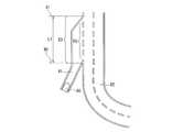
- the switching point registration unit 71sets a point at a predetermined distance D1 from the merging section 63 as a switching point. sign up. Please refer to FIG. If the height difference between the traveling lane 61 of the vehicle 60 and the main line 62 is equal to or greater than the predetermined value H1 at a point before the merging section 63 by a predetermined distance D1, the road structure is The main line 62 is hidden in a blind spot caused by an object.
- switching point registration unit 71sets the height difference between traveling lane 61 of main vehicle 60 and main line 62 at a predetermined height H1 or more at a point before predetermined distance D1 from merging section 63, and traveling lane 61 is the main line. If it is lower than 62, a point before the predetermined distance D1 from the merging section 63 is registered as a switching point. On the other hand, even if the height difference between the traveling lane 61 and the main line 62 is equal to or more than the predetermined height H1, no blind spot occurs when the traveling lane 61 is higher than the main line 62. Therefore, the switching point registration unit 71 does not register the switching point.
- the switching point registration unit 71selects the traveling lane 61 and the main line. A point before the predetermined distance D1 from the merging section 63 is registered as a switching point regardless of the height difference between the point 62 and the point 62. On the other hand, when there is no shield 90 having a predetermined height H2 or more, the switching point registration unit 71 does not register the switching point.
- the traffic condition of the main line 62may not be determined due to the road shape of the traveling lane 61 of the host vehicle 60 and the road shape of the main line 62 at a point before the merging section 63 by a predetermined distance D1.
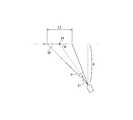
- FIG. 8 and FIG. 9show an example where the traffic condition of the main line 62 can not be determined in the road shape. Please refer to FIG. If the difference ⁇ between the traveling direction 91 of the traveling lane 61 and the traveling direction 92 of the main line 62 at a point before the predetermined distance D1 from the merging section 63 is large, the detection range 93 of the surrounding environment sensor group 10 in front of the own vehicle 60 is entered.
- the length L2 of the range of the main line 62(that is, the range in which the traffic condition can be detected by the ambient environment sensor group 10) may be short, and the traffic condition of the main line 62 may not be determined.
- the difference ⁇ between the traveling direction 91 of the traveling lane 61 and the traveling direction 92 of the main line 62further increases and approaches 180 degrees, one of the other vehicles 64 is the other as viewed from a predetermined distance D1 from the merging section 63. Because the vehicle is hidden by the other vehicle 64, it may not be possible to determine the traffic condition of the main line 62.
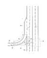
- the main line 62is curved as shown in FIG. 9, “the advancing direction 92 of the main line 62” is an extension of the advancing direction 91 of the traveling lane 61 and the main line at a point before the merging section 63 by a predetermined distance D1. It may be defined as the traveling direction of the main line 62 at the point 94 where it intersects with 62.
- the switching point registration unit 71is selected from the merging section 63 when the difference ⁇ between the traveling direction 91 of the traveling lane 61 and the traveling direction 92 of the main line 62 at a point before the merging section 63 by a predetermined distance D1 is equal to or greater than a predetermined threshold.
- a point in front of the distance D1is registered as a switching point.
- the threshold of the difference ⁇may be set based on the threshold L 3 of the length of the range in which the traffic condition of the main line 62 is to be detected by the ambient environment sensor group 10.
- the detection range of the surrounding environment sensor group 10is a range of the azimuth angle width ⁇ centered on the traveling direction 91 of the vehicle 60, and the traveling direction 92 of the main line 62 extends from a point before the merging section 63 by a predetermined distance D1.
- Pbe the length of the perpendicular to the line.
- the length L2 of the detection range of the main line 62 by the ambient environment sensor group 10can be obtained by the following equation (1).
- the threshold of the difference ⁇can be calculated as the upper limit value of the range of the difference ⁇ in which the length L2 is longer than the threshold L3.
- a portion 94 of the main line 62exists on an extension of the traveling direction 91 of the traveling lane 61 at a point before the merging section 63 by a predetermined distance D1.
- a distance from a point before the predetermined distance D1 from the merging section 63 to the portion 94is D2. If the distance D2 is too long, the detection resolution of the other vehicle 64 on the main line 62 falling within the detection range 93 of the ambient environment sensor group 10 may be reduced, making it impossible to determine the traffic condition of the main line 62.
- the switching point registration unit 71registers a point that is a predetermined distance D1 before the merging section 63 as a switching point.
- the high difficulty pointis not limited to only the merging section 63, and may be a point having another road shape in which the traveling lane of the host vehicle and another lane are connected.
- the high difficulty point extraction unit 70may extract an intersection where the traveling lane 61 of the own vehicle intersects with another lane as a point where the traveling lane of the own vehicle and the other lane are connected.
- the intersectionmay include, for example, a crossroad or a T-junction.
- the high difficulty point extraction unit 70may extract an intersection at which the traveling lane 61 of the host vehicle intersects with the other lane 62 as a high difficulty point. For example, when turning right at the intersection of the driving lane 61 and another lane 62 along the traveling track 95 of automatic driving, it is assumed that there is another vehicle 64 that obstructs the right turn of the vehicle 60 due to traffic congestion in the other lane 62 In automatic driving, it may be difficult to change lanes to the main lane 62. The same applies to the case where the host vehicle 60 turns left.
- the switching point registration unit 71registers the point by a predetermined distance D1 from the intersection as a switching point. .
- the switching point registration unit 71records, in the storage unit 72, a point that is a predetermined distance D1 before the intersection.
- the switching point registration unit 71may register the switching point by storing the intersection in the storage unit 72 instead of the point at a predetermined distance D1 before the intersection.
- the switching guide to the manual drivingcan be performed at the timing according to the traffic condition of the other lane 62 . Therefore, when it is considered that the traffic condition of the other lane 62 can be determined at a point in the predetermined distance D1 before the intersection, the switching point registration unit 71 does not register the point in the predetermined distance D1 from the intersection as the switching point. As a result, automatic driving can be continued to reduce the driver's driving load.
- the switching point registration unit 71when there is a roadside zone within a predetermined radius R from the center of the intersection, the switching point registration unit 71 has good visibility of the intersection and determines the traffic situation of the other lane 62 at a point before the predetermined distance D1 from the intersection. Since it is considered that it is possible, a point in front of the intersection by a predetermined distance D1 is not registered as a switching point. Further, even when the pedestrian road exists in front of the intersection, the switching point registration unit 71 does not register the point at a predetermined distance D1 from the intersection as the switching point.
- the switching point registration unit 71registers a point at a predetermined distance D1 from the intersection as a switching point. For example, if the other vehicle 64 exists in the range shown by the dotted line 97 on the other lane 62, automatic driving along the traveling track 95 becomes difficult. Therefore, when the range 97 is hidden behind the shielding object 96 when viewed from a point before the predetermined distance D1 from the intersection, the switching point registration unit 71 registers a point before the predetermined distance D1 from the intersection as the switching point.
- the switching control unit 73reads the switching point recorded in the storage unit 72 while the host vehicle 60 is in automatic driving. The switching control unit 73 determines whether the host vehicle 60 has reached the switching point. When the own vehicle 60 reaches the switching point, the switching control unit 73 guides the switching of the traveling state of the own vehicle 60 from the automatic driving mode to the manual driving mode.
- the switching control unit 73determines that the vehicle 60 is at a point before the predetermined distance D1 from the high difficulty point. It is determined whether it has reached. When the own vehicle 60 reaches a point near the predetermined distance D1 from the high difficulty point, the switching control unit 73 guides the switching of the traveling state of the own vehicle 60 from the automatic driving mode to the manual driving mode.
- the switching control unit 73outputs a voice guidance message for prompting the driver to switch the traveling state of the vehicle 60 from the automatic driving mode to the manual driving mode by the operation of the switching switch 43 from the voice output unit 26 of the navigation system 20 You may Further, for example, the switching control unit 73 may use a voice guidance message for prompting the driver to switch the traveling state of the vehicle 60 from the automatic driving mode to the manual driving mode by any operation of the steering wheel, the accelerator pedal, and the brake pedal. It may be output from the audio output unit 26.
- the switching control unit 73displays a visual guidance message for prompting the driver to switch the traveling state of the vehicle 60 from the automatic driving mode to the manual driving mode by the operation of the switching switch 43. It may be displayed on Further, for example, the switching control unit 73 is a visual guidance message for prompting the driver to switch the traveling state of the vehicle 60 from the automatic driving mode to the manual driving mode by the operation of any one of the steering wheel, the accelerator pedal, and the brake pedal. May be displayed on the display unit 24.
- the switching control unit 73outputs, from the voice output unit 26 or the display unit 24, a voice guidance message or a visual guidance message notifying that the traveling state of the own vehicle 60 is automatically switched from the automatic driving mode to the manual driving mode. May be
- FIG. 12is a flowchart of an example of registration processing of a switching point for the merging section.
- the high difficulty point extraction unit 70extracts merging sections A1, A2,... AM present on the planned traveling route as candidates for high difficulty points.
- the total number of merging sections A1 to AM extracted at this timeis M.
- 1is substituted for the variable i.
- step S3the high difficulty point extraction unit 70 reads road map data of the merging section Ai of the merging sections A1 to AM from the map database 23.
- step S4the high difficulty point extraction unit 70 determines whether the distance L1 from the start point of the merging section Ai to the end point is less than a threshold. If the distance L1 is less than the threshold (step S4: Y), the high difficulty point extraction unit 70 determines that the merging section Ai is a high difficulty point, and advances the process to step S5. If the distance L1 is not less than the threshold (step S4: N), the high difficulty point extraction unit 70 determines that the merging section Ai is not a high difficulty point, and advances the process to step S10.
- step S5based on the road map data in the vicinity of the merging section Ai, the switching point registration unit 71 determines that the height difference between the traveling lane 61 of the vehicle 60 and the main line 62 at a point before the merging section Ai by a predetermined distance D1. It is determined whether or not the traveling lane 61 is lower than the main line 62, which is equal to or greater than the predetermined value H1. When the height difference is equal to or more than the predetermined value H1 and the traveling lane 61 is lower than the main line 62, the main line 62 is hidden in a blind spot, and such a point needs to be registered as a switching point.
- step S5: YIf the height difference is greater than or equal to the predetermined value H1 and the traveling lane 61 is lower than the main line 62 (step S5: Y), the process proceeds to step S6. If the height difference is not the predetermined value H1 or more, or if the traveling lane 61 is higher than the main line 62 (step S5: N), the process proceeds to step S7.
- step S6the switching point registration unit 71 registers a point that is a predetermined distance D1 before the merging section Ai as a switching point.
- the merging section Aiis stored in the storage unit 72.
- step S7the switching point registration unit 71 determines whether or not there is a shield having a predetermined height H2 or more between the traveling lane 61 and the main line 62 at a point before the merging section 63 by a predetermined distance D1. When such a shield is present, it is necessary to register such a point as a switching point because the main line 62 is hidden in the blind spot.
- step S7: YIf there is a shield having a predetermined height H2 or more between the traveling lane 61 and the main line 62 (step S7: Y), the process proceeds to step S6. If there is no shield of the predetermined height H2 or more between the traveling lane 61 and the main line 62 (step S7: N), the process proceeds to step S8.
- step S8the switching point registration unit 71 can not determine the traffic situation of the main line 62 due to the road shape of the traveling lane 61 of the host vehicle 60 and the road shape of the main line 62 at a point before the merging section 63 by a predetermined distance D1. It is determined whether or not
- the switching point registration unit 71includes a portion 94 of the main line 62 existing on an extension of the traveling direction of the traveling lane 61 at a predetermined distance D1 from the merging section 63 and a point before the predetermined distance D1 from the merging section 63. It is determined whether the distance D2 (see FIG. 9) between them is equal to or greater than a predetermined value. If the distance D2 is equal to or more than a predetermined value, it is determined that the detection resolution of the other vehicle 64 on the main line 62 falling within the detection range of the surrounding environment sensor group 10 is equal to or less than the allowable value and the traffic condition can not be determined. If the traffic condition can not be determined (step S8: Y), the process proceeds to step S6. If the traffic condition is not determined (step S8: N), the process proceeds to step S9.
- the switching point registration unit 71has a length L2 of the main line range where the traffic condition of the main line 62 can be detected by the surrounding environment sensor group 10 at a point before the predetermined distance D1 from the merging section 63 is less than the predetermined length. It is determined whether the For example, when the difference ⁇ between the traveling direction of the traveling lane 61 and the traveling direction of the main line 62 at a point located a predetermined distance D1 before the merging section is longer than a predetermined threshold (see FIG. 8) May be determined to be less than a predetermined length.
- step S9: YThe traffic condition of the main line 62 can not be determined if the length L2 for which the traffic condition of the main line 62 can be detected by the ambient environment sensor group 10 is too short. Therefore, when the length L2 is less than the predetermined length (step S9: Y), the process proceeds to step S6. If the length L2 is not less than the predetermined length (step S9: N), the process proceeds to step S10. In step S10, the variable i is increased by one. In step S11, it is determined whether or not the variable i is larger than the total number M of merging sections A1 to AM, that is, it is determined whether registration of switching points is necessary or not for all extracted merging sections. If the variable i is larger than the total number M (Y in step S11), the process ends. If the variable i is equal to or less than the total number M (step S11: N), the process returns to step S3.
- FIG. 13is a flowchart of an example of registration processing of a switching point for an intersection.
- the high difficulty point extraction unit 70extracts intersections B1, B2,... BN present on the planned traveling route as high difficulty points.
- the total number of intersections B1 to BN extracted at this timeis N.
- 1is substituted for the variable i.
- the switching point registration unit 71reads road map data of the intersection Bi of the intersections B1 to BN from the map database 23.
- step S23the switching point registration unit 71 determines whether there is a roadside band within a predetermined radius R from the center of the intersection Bi.
- the intersection Biis well visible, and therefore, it is not necessary to register a point in the vicinity of the predetermined distance D1 from the intersection Bi as a switching point. Therefore, when there is a roadside zone within a predetermined radius R from the center of the intersection Bi (step S23: Y), step S26 for registering the switching point is skipped, and the process proceeds to step S27. If there is no roadside zone within the predetermined radius R from the center of the intersection Bi (step S23: N), the process proceeds to step S24.
- step S24the switching point registration unit 71 determines whether a pedestrian road exists in front of the intersection Bi. Even when there is a pedestrian road in front of the intersection Bi, the intersection Bi may have a good visibility, so it is not necessary to register a point in the vicinity of the predetermined distance D1 from the intersection Bi as a switching point. Therefore, when there is a pedestrian road before the intersection Bi (step S24: Y), the process proceeds to step S27. If the pedestrian road does not exist in front of the intersection Bi (step S24: N), the process proceeds to step S25.
- step S25the switching point registration unit 71 determines whether the shield 96 is present at the corner of the intersection Bi.
- the shield 96exists at the corner of the intersection Bi
- the other lane 62 crossing the traveling lane 61is hidden in the blind spot of the shield 96, and the traffic condition of the other lane 62 becomes difficult to determine. Therefore, when the shield 96 exists at the corner of the intersection Bi (step S25: Y), the process proceeds to step S26. If there is no shield 96 at the corner of the intersection Bi (step S25: N), the process proceeds to step S27.
- step S26the switching point registration unit 71 registers a point at a predetermined distance D1 before the intersection Bi as a switching point.
- the intersection Biis stored in the storage unit 72.
- step S27the variable i is increased by one.
- step S28it is determined whether or not the variable i is larger than the total number N of the intersections B1 to BN, that is, it is determined whether or not the switching points need to be registered for all of the extracted intersections. If the variable i is larger than the total number N (Y in step S28), the process ends. If the variable i is equal to or less than the total number N (step S28: N), the process returns to step S22.
- FIG. 14is a flowchart of switching guidance of the traveling state during traveling of the vehicle 60.
- the switching control unit 73reads from the storage unit 72 the point closest to the current position of the vehicle 60, from the junction recorded in step S6 in FIG. 12 and the intersection recorded in step S26 in FIG.
- the switching control unit 73determines whether or not the vehicle 60 has reached a point that is a predetermined distance D1 before the point read in step S30.
- step S31: YWhen the vehicle 60 reaches a point before the predetermined distance D1 from the point read in step S30 (step S31: Y), the switching control unit 73 determines that it is the timing of the switching guide to the manual driving, and performs the process Proceed to S32. If the vehicle 60 has not arrived at a point before the predetermined distance D1 from the point read in step S30 (step S31: N), the process returns to step SS31.
- step S32the switching control unit 73 guides the switching of the traveling state of the vehicle 60 from the automatic driving mode to the manual driving mode.
- step S33the switching control unit 73 receives the switching operation to the manual driving mode by the driver.
- step S34the switching control unit 73 switches the traveling state of the vehicle 60 from the automatic driving mode to the manual driving mode.
- the switching control unit 73receives the switching operation from the manual driving mode to the automatic driving mode by the driver in step S35.
- the switching control unit 73 that has received the switching operationswitches the traveling state of the host vehicle 60 from the manual driving mode to the automatic driving mode.
- the switching control unit 73determines whether a merging section or an intersection not read yet in step S30 remains on the planned traveling route. If there is a merging section or intersection not read yet (step S36: Y), the process returns to step S30. If there are no merging sections or intersections not yet read (step S36: N), the process ends.
- the high difficulty point extraction unit 70extracts a point where the traveling lane of the vehicle 60 and another lane are connected on the planned traveling route as a high difficulty point where automatic driving is difficult.
- the switching control unit 73guides switching of the traveling state of the vehicle 60 from the automatic driving to the manual driving at a point before the predetermined distance D1 from the high difficulty point.
- the high difficulty pointis the merging section 63 where the traveling lane 61 merges with the main lane 62 which is the other lane with a lane change, and the distance from the starting point 80 to the ending point 81 of the merging section 63 or travel
- the merging section 63may have a time shorter than the threshold. Because there are few opportunities to change lanes in short merging sections, automatic driving may be difficult depending on traffic conditions such as congestion. By extracting a short junction section accompanied by a lane change as a high difficulty point and performing switching guidance from automatic driving to manual driving in front of it, the driver can start manual driving with a margin.
- the switching control unit 73is traveling from automatic driving to manual driving at a predetermined distance D1 from the merging section 63. Guide the switching of If it is not possible to judge the traffic condition of the main line 62 until reaching the merging section 63 and it is not possible to judge whether merging by automatic driving is difficult, whether to be able to guide switching from automatic driving to manual driving with margin. I do not know.
- the switching control unit 73When the height difference between the traveling lane 61 and the main line 62 is the predetermined value H1 or more and the traveling lane 61 is lower than the main line 62 at a point before the predetermined distance D1 from the merging section 63, the switching control unit 73 The switching of the traveling state from the automatic driving to the manual driving is guided at a point before the predetermined distance D1 from the merging section 63. Thereby, when the height difference between the traveling lane 61 and the main line 62 is equal to or more than the predetermined value H1 and the traveling lane 61 is lower than the main line 62, it can be determined that the main line 62 is hidden in the blind spot.
- the switching control unit 73 at a point before the predetermined distance D1 from the merging section 63Guide switching of the driving condition from automatic driving to manual driving. As a result, when the shield 90 exists between the traveling lane 61 and the main line 62, it can be determined that the main line 62 is hidden in the blind spot.
- the switching control unit 73At a point before the predetermined distance D1 from the section 63, switching of the traveling state from the automatic driving to the manual driving is guided. Thereby, when it is considered that the traffic situation of the main line 62 can not be determined at a point before the predetermined distance D1 from the merging section 63, switching of the traveling state from automatic driving to manual driving at a point before the predetermined distance D1 from the merging section 63 It is possible to give guidance and allow the driver to start manual operation with a margin.
- the switching control unit 73merges when the difference ⁇ between the traveling direction 91 of the traveling lane 61 and the traveling direction 92 of the main line 62 at a point before the merging distance 63 by a predetermined distance D1 is equal to or greater than a predetermined threshold. At a point before the predetermined distance D1 from the section 63, switching of the traveling state from the automatic driving to the manual driving is guided. Thus, when the difference ⁇ is equal to or more than the predetermined threshold value, it can be determined that the traffic condition of the main line 62 can not be determined due to the road shape of the traveling lane 61 and the road shape of the main line 62.
- D2is equal to or greater than the predetermined value
- the switching control unit 73guides the switching of the traveling state from the automatic driving to the manual driving at a point before the predetermined distance D1 from the merging section 63. Accordingly, when the distance D2 is equal to or more than the predetermined value, it can be determined that the traffic condition of the main line 62 can not be determined due to the road shape of the traveling lane 61 and the road shape of the main line 62.
- the switching control unit 73switches the traveling state of the host vehicle 60 from the automatic driving to the manual driving at a point near the predetermined distance D1 from the high difficulty point.
- switching to manual operationis performed before the connection point, so that the driver can start manual operation with a margin. For this reason, it is possible to suppress the driver's confusion caused by the switching being performed near the connection point (for example, immediately before the connection point).
Landscapes
- Engineering & Computer Science (AREA)
- Automation & Control Theory (AREA)
- Remote Sensing (AREA)
- Radar, Positioning & Navigation (AREA)
- Transportation (AREA)
- Mechanical Engineering (AREA)
- General Physics & Mathematics (AREA)
- Physics & Mathematics (AREA)
- Human Computer Interaction (AREA)
- Multimedia (AREA)
- Theoretical Computer Science (AREA)
- Traffic Control Systems (AREA)
- Navigation (AREA)
Abstract
Description
Translated fromJapanese本発明は、運転支援方法及び運転支援装置に関する。The present invention relates to a driving support method and a driving support device.
特許文献1には、自車両が走行する走行路と他の道路とが合流する合流地点付近において、自車両と他の道路との間に遮蔽物が存在するか否かを判断し、遮蔽物が存在していれば、他の道路が存在する方向へと自車両を車幅方向に沿って移動させる運転支援装置が記載されている。According to
自車両の走行車線と他の車線とが接続する接続地点の道路構造などによっては、他の車線の交通状況を判定することができず自動運転を続けることが困難になる。例えば、渋滞している本線へ合流するときに自動運転で自車両を走行させている場合に、接続地点に着いてから本線上の他車両の前へ割り込めないと自動運転制御において判定され、自動運転から手動運転への自車両の走行状態の切り替え案内が行われてしまう。そのため、接続地点での案内により運転者は急な操作を強いられて困惑することがある。
本発明は、接続地点で自動運転から手動運転への自車両の走行状態の切り替え案内が行われることによる運転者の困惑を抑制することを目的とする。Depending on the road structure of the connection point where the traveling lane of the host vehicle and the other lane are connected, it is difficult to determine the traffic situation of the other lane and it becomes difficult to continue the automatic driving. For example, when the host vehicle is made to travel by automatic driving when joining a traffic jammed main line, it is determined in automatic driving control that it can not interrupt in front of other vehicles on the main line after arriving at the connection point. Switching guidance of the traveling state of the host vehicle from driving to manual driving is performed. Therefore, the driver at the connection point may be confused by being forced to make a sudden operation.
An object of the present invention is to suppress a driver's embarrassment caused by switching guidance of the traveling state of the vehicle from automatic driving to manual driving at a connection point.
本発明の一態様に係る運転支援方法は、自車両の走行予定の経路上において自車両の走行車線と他の車線とが接続する地点を自動運転が困難な高難度地点として抽出し、高難度地点から所定距離手前の地点において自動運転から手動運転への自車両の走行状態の切り替えを案内する。The driving support method according to an aspect of the present invention extracts a point where the traveling lane of the own vehicle and another lane are connected on a route planned to travel of the own vehicle as a high difficulty point where automatic driving is difficult, At a point before a predetermined distance from the point, switching of the traveling state of the vehicle from automatic driving to manual driving is guided.
本発明の一態様によれば、自車両の走行車線と他の車線とが接続する接続地点で自動運転から手動運転への自車両の走行状態の切り替え案内が行われることによる運転者の困惑を抑制できる。
本発明の目的及び利点は、特許請求の範囲に示した要素及びその組合せを用いて具現化され達成される。前述の一般的な記述及び以下の詳細な記述の両方は、単なる例示及び説明であり、特許請求の範囲のように本発明を限定するものでないと解するべきである。According to one aspect of the present invention, the driver's embarrassment is caused by switching guidance of the traveling state of the vehicle from automatic driving to manual driving at a connection point where the traveling lane of the vehicle and another lane are connected. It can be suppressed.
The objects and advantages of the present invention are realized and attained by means of the elements and combinations thereof as set forth in the appended claims. It is to be understood that both the foregoing general description and the following detailed description are exemplary and explanatory only and are not restrictive of the invention, as claimed.
以下、本発明の実施形態について、図面を参照しつつ説明する。
(第1実施形態)
(構成)
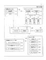
図1を参照する。運転支援装置1は、運転支援装置1を搭載する車両(以下、「自車両」と表記する)の周囲の走行環境に基づいて、自車両を自動的に操舵したり停車させる走行支援制御と、運転者が関与せずに自車両を自動で運転する自動運転制御を行う。
運転支援装置1は、周囲環境センサ群10と、ナビゲーションシステム20と、車両センサ群30と、コントローラ40と、切替スイッチ43と、車両制御アクチュエータ群50を備える。Hereinafter, embodiments of the present invention will be described with reference to the drawings.
First Embodiment
(Constitution)
Please refer to FIG. The
The
周囲環境センサ群10は、自車両の周囲環境、例えば自車両の周囲の物体を検出するセンサ群である。周囲環境センサ群10は、測距装置11とカメラ12を含んでよい。測距装置11とカメラ12は、自車両周囲に存在する物体、車両と物体との相対位置、車両と物体との距離等の車両の周囲環境を検出する。
測距装置11は、例えば、レーザレンジファインダ(LRF:Laser Range-Finder)やレーダであってよい。The ambient
The distance measuring apparatus 11 may be, for example, a laser range finder (LRF) or a radar.
カメラ12は、例えばステレオカメラであってよい。カメラ12は、単眼カメラであってもよく、単眼カメラにより複数の視点で同一の物体を撮影して、物体までの距離を計算してもよい。
測距装置11とカメラ12は、検出した周囲環境の情報である周囲環境情報をコントローラ40へ出力する。The
The distance measuring device 11 and the
ナビゲーションシステム20は、自車両の現在位置と、その現在位置における道路地図情報を認識する。ナビゲーションシステム20は、乗員が入力した目的地までの走行経路を設定し、この走行経路に従って乗員に経路案内を行う。さらにナビゲーションシステム20は、設定した走行経路の情報をコントローラ40へ出力する。自車両の走行状態が自動運転モードである場合、コントローラ40は、ナビゲーションシステム20が設定した走行経路に沿って走行するように自車両を自動で運転する。The
ナビゲーションシステム20は、ナビコントローラ21と、測位装置22と、地図データベース23と、表示部24と、操作部25と、音声出力部26と、通信部27を備える。なお、図1において地図データベースを地図DBと表記する。
ナビコントローラ21は、ナビゲーションシステム20の情報処理動作を制御する電子制御ユニットである。ナビコントローラ21は、プロセッサとその周辺部品とを含む。
プロセッサは、例えばCPU(Central Processing Unit)、やMPU(Micro-Processing Unit)であってよい。The
The
The processor may be, for example, a central processing unit (CPU) or a micro-processing unit (MPU).
周辺部品には記憶装置等が含まれる。記憶装置は、半導体記憶装置、磁気記憶装置及び光学記憶装置のいずれかを備えてよい。記憶装置は、レジスタ、キャッシュメモリ、主記憶装置として使用されるROM(Read Only Memory)及びRAM(Random Access Memory)等のメモリを含んでよい。
測位装置22は、自車両の現在位置を測定する。測位装置22は、例えばGPS(Global Positioning System)受信器であってよい。また測位装置22は、GLONASS(Global Navigation Satellite System)等の他の衛星測位システムの衛星信号に基づいて自車両の現在位置を測定してもよい。また測位装置22は、慣性航法装置であってもよい。Peripheral parts include storage devices and the like. The storage device may comprise any of a semiconductor storage device, a magnetic storage device, and an optical storage device. The storage device may include a memory such as a register, a cache memory, a read only memory (ROM) used as a main storage device, and a random access memory (RAM).
The positioning device 22 measures the current position of the vehicle. The positioning device 22 may be, for example, a GPS (Global Positioning System) receiver. The positioning device 22 may also measure the current position of the vehicle based on satellite signals of another satellite positioning system such as GLONASS (Global Navigation Satellite System). The positioning device 22 may also be an inertial navigation device.
地図データベース23は、道路地図データを記憶している。道路地図データは、道路線種、道路形状、勾配、車線数、法定速度(制限速度)、合流地点の有無等に関する情報を含む。道路線種には、例えば一般道路と高速道路が含まれる。
表示部24は、ナビゲーションシステム20において様々な視覚的情報を出力する。例えば、表示部24には、自車両周囲の地図画面や推奨経路の案内を表示してよい。The map database 23 stores road map data. Road map data includes information on road line type, road shape, slope, number of lanes, legal speed (speed limit), presence or absence of junction, and the like. Road line types include, for example, general roads and expressways.
The
操作部25は、ナビゲーションシステム20において乗員の操作を受け付ける。操作部25は、例えばボタン、ダイヤル、スライダなどであってよく、表示部24に設けられたタッチパネルであってもよい。例えば操作部25は、乗員による目的地の入力操作や、表示部24の表示画面の切り替え操作を受け付けてよい。
音声出力部26は、ナビゲーションシステム20において様々な音声情報を出力する。音声出力部26は、設定した走行経路に基づく運転案内や、自車両周囲の道路地図データに基づく道路案内情報を出力してよい。
通信部27は、自車両の外部の通信装置との間で無線通信を行う。通信部27による通信方式は、例えば公衆携帯電話網による無線通信や、車車間通信、路車間通信、又は衛星通信であってよい。The
The
The
車両センサ群30は、車両の走行状態を検出するセンサと、運転者により行われた運転操作を検出するセンサとを含む。
車両の走行状態を検出するセンサには、車速センサ31と、加速度センサ32と、ジャイロセンサ33が含まれる。
運転操作を検出するセンサには、操舵角センサ34と、アクセルセンサ35と、ブレーキセンサ36が含まれる。The
The sensors that detect the traveling state of the vehicle include a
The sensors for detecting the driving operation include a
車速センサ31は、自車両の車輪速を検出し、車輪速に基づいて自車両の速度を算出する。
加速度センサ32は、自車両の前後方向の加速度、車幅方向の加速度及び上下方向の加速度を検出する。
ジャイロセンサ33は、ロール軸、ピッチ軸及びヨー軸を含む3軸回りの自車両の回転角度の角速度を検出する。The
The
The
操舵角センサ34は、操舵操作子であるステアリングホイールの現在の回転角度(操舵操作量)である現在操舵角を検出する。
アクセルセンサ35は、車両のアクセル開度を検出する。例えばアクセルセンサ35は、車両のアクセルペダルの踏み込み量をアクセル開度として検出する。
ブレーキセンサ36は、運転者によるブレーキ操作量を検出する。例えばブレーキセンサ36は、車両のブレーキペダルの踏み込み量をブレーキ操作量として検出する。
車両センサ群30の各センサが検出した自車両の速度、加速度、角速度、操舵角、アクセル開度、ブレーキ操作量の情報を総称して「車両情報」と表記する。車両センサ群30は車両情報をコントローラ40へ出力する。The
An
The brake sensor 36 detects the amount of brake operation by the driver. For example, the brake sensor 36 detects the depression amount of the brake pedal of the vehicle as a brake operation amount.
Information on the speed, acceleration, angular velocity, steering angle, accelerator opening degree, and brake operation amount of the own vehicle detected by each sensor of the
コントローラ40は、自車両の運転制御を行う電子制御ユニットである。コントローラ40は、プロセッサ41と、記憶装置42等の周辺部品とを含む。プロセッサ41は、例えばCPUやMPUであってよい。
記憶装置42は、半導体記憶装置、磁気記憶装置及び光学記憶装置のいずれかを備えてよい。記憶装置42は、レジスタ、キャッシュメモリ、主記憶装置として使用されるROM及びRAM等のメモリを含んでよい。
なお、汎用の半導体集積回路中に設定される機能的な論理回路でコントローラ40を実現してもよい。例えば、コントローラ40はフィールド・プログラマブル・ゲート・アレイ(FPGA:Field-Programmable Gate Array)等のプログラマブル・ロジック・デバイス(PLD:Programmable Logic Device)等を有していてもよい。The
The
The
自車両の自動運転制御が実行される自動運転モードでは、コントローラ40は、周囲環境センサ群10から入力した周囲環境情報と、車両センサ群30から入力した車両情報とに基づいて、ナビゲーションシステム20により設定された走行経路を自車両に走行させる走行軌道を生成する。
コントローラ40は、生成した走行軌道を自車両が走行するように車両制御アクチュエータ群50を駆動して自動的に車両を走行させる。In the automatic driving mode in which the automatic driving control of the own vehicle is executed, the
The
車両制御アクチュエータ群50は、コントローラ40からの制御信号に応じて、車両のステアリングホイール、アクセル開度及びブレーキ装置を操作して、車両の車両挙動を発生させる。車両制御アクチュエータ群50は、ステアリングアクチュエータ51と、アクセル開度アクチュエータ52と、ブレーキ制御アクチュエータ53を備える。
ステアリングアクチュエータ51は、車両のステアリングの操舵方向及び操舵量を制御する。
アクセル開度アクチュエータ52は、車両のアクセル開度を制御する。
ブレーキ制御アクチュエータ53は、車両のブレーキ装置の制動動作を制御する。The vehicle
The steering
The
The
手動運転モードでは、コントローラ40は、例えば、車両センサ群30により検出された操舵角、アクセル開度及びブレーキ操作量に応じて車両制御アクチュエータ群50を駆動して、運転者の操作に応じた車両挙動を発生させる。
運転者は切替スイッチ43を操作することにより、自車両の走行状態を自動運転モードと手動運転モードとの間で切り替えることができる。In the manual operation mode, the
The driver can switch the traveling state of the host vehicle between the automatic driving mode and the manual driving mode by operating the
コントローラ40は、運転者による切替スイッチ43の操作に応じて自車両の走行状態を自動運転モードと手動運転モードとの間で切り替える。
また、コントローラ40は、自動運転中の運転者によるステアリングホイール、アクセルペダル、ブレーキペダルの何れかの操作、すなわちオーバライドが起こったときに、自車両の走行状態を自動運転モードから手動運転モードへ切り替える。The
Further, the
さらに、コントローラ40は、自車両の走行予定の経路(例えば自動運転の走行経路)に自動運転による走行が困難な地点がある場合に、高難度地点から所定距離手前の地点において自動運転から手動運転への自車両の走行状態の切り替えを案内する。
以下、自車両の走行予定の経路を「予定走行経路」と表記することがある。また、自動運転による自車両の走行が困難な地点(例えば自動運転による自車両の走行の難度が高い地点)を「高難度地点」と表記する。
高難度地点は、例えば、混雑度などの交通状況によって自車両の難度が高くなる地点であってよい。例えば高難度地点には、図2に示すような複数の道路が合流する合流場所において、自車両60の走行車線である合流車線61と、合流先車線62とが合流する合流区間63が含まれる。以下、本明細書において合流先車線を「本線」と表記する。Furthermore, when there is a point where traveling by automatic driving is difficult in a route (for example, a traveling route of automatic driving) where the vehicle is scheduled to travel, the
Hereinafter, a route scheduled to travel of the vehicle may be referred to as a "scheduled travel route". Further, a point where traveling of the host vehicle by automatic driving is difficult (for example, a point where the difficulty of traveling of the host vehicle by automatic driving is high) is referred to as a “high difficulty level point”.
The high difficulty point may be, for example, a point where the degree of difficulty of the host vehicle becomes high depending on traffic conditions such as congestion. For example, the high difficulty point includes a merging
図2に示すように本線が渋滞していると、自車両60が本線62へ進入しようとする際に、合流区間63の本線62には、自車両60の進入の障害となる他車両64が存在することを周囲環境センサ群10により検出する。渋滞のため複数の他車両64が順次絶えずに本線62上で検出されると、自動運転では本線62へ車線変更を行うことが困難になる。
このような場合に、自車両60が合流区間63の近くに到達してから自動運転から手動運転への自車両の走行状態の切り替え案内をすると、合流区間63の近くでの切り替え案内により運転者は急な操作を強いられ困惑することがある。As shown in FIG. 2, when the main line is congested, when the
In such a case, when the traveling guidance of the own vehicle from automatic driving to manual driving is notified after the
そこで、コントローラ40は、予定走行経路上の高難度地点を抽出し、高難度地点から所定距離D1手前の地点において自動運転から手動運転への自車両の走行状態の切り替えを案内する。
これにより、高難度地点の手前で自動運転から手動運転へ走行状態を切り替えることができるので、運転者は余裕をもって手動運転を開始できる。Therefore, the
Thus, the driving state can be switched from the automatic driving to the manual driving before the high difficulty point, so that the driver can start the manual driving with a margin.
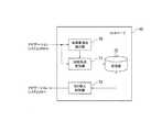
次に、コントローラ40の機能構成を説明する。図3を参照する。コントローラ40は、高難度地点抽出部70と、切替地点登録部71と、記憶部72と、切り替え制御部73を備える。
高難度地点抽出部70、切替地点登録部71、及び切り替え制御部73の機能は、コントローラ40のプロセッサ41が、記憶装置42に格納されたコンピュータプログラムを実行することによって実現されてよい。Next, the functional configuration of the
The functions of the high difficulty
高難度地点抽出部70は、ナビゲーションシステム20から、ナビゲーションシステム20により設定された予定走行経路上の各地点の道路地図データを取得する。高難度地点抽出部70は、ナビゲーションシステム20から取得した道路地図データに基づいて、予定走行経路上に存在する高難度地点を抽出する。
例えば高難度地点抽出部70は、自車両の走行車線と他の車線とが接続する地点を高難度地点として抽出してよい。The high difficulty
For example, the high difficulty
自車両の走行車線と他の車線とが接続する地点には、例えば自車両の走行車線が他の車線へ合流する合流区間が含まれる。高難度地点抽出部70は、例えば図4Aに示す合流区間63を高難度地点として抽出してよい。
合流区間63は、本線62への合流が合流車線61から本線62への車線変更を伴う合流区間である。For example, a junction where the traveling lane of the own vehicle merges with the other lane is included at a point where the traveling lane of the own vehicle and the other lane are connected. For example, the high difficulty
The merging
複数の道路が合流する場所には、図4Bに示す合流地点のように合流地点で車線変更を要しない場所も存在する。高難度地点抽出部70は、図4Bに示す合流地点を高難度地点から除外してもよい。
図4Aを参照する。合流区間63の開始地点80から終了地点81までの区間に自車両60が滞在できる期間が短いほど、本線62へ車線変更できる機会が少なくなり本線62への合流の難度が高くなる。Where multiple roads join, there are places where it is not necessary to change lanes at the junction, such as the junction shown in FIG. 4B. The high difficulty
Please refer to FIG. 4A. As the period in which the
このため、例えば高難度地点抽出部70は、合流区間63の開始地点80から終了地点81までの距離L1が閾値未満の場合に合流区間63を高難度地点として抽出してよい。
この閾値は、例えば、開始地点80から1回程度しか合流を試みることしかできない距離に設定してよい。また、合流区間63においてウインカ点灯後3秒以上走行できない距離に設定してよい。Therefore, for example, when the distance L1 from the
This threshold may be set, for example, to a distance from the
また例えば、高難度地点抽出部70は、合流区間63における自車両60の速度を予測し、予測した速度と距離Lとに基づいて開始地点80から終了地点81までの自車両60の走行時間を予測する。走行時間が閾値未満の場合に、合流区間63を高難度地点として抽出してよい。高難度地点抽出部70は、合流区間63における法定制限速度に基づいて合流区間63における自車両60の速度を予測してよく、自車両60の現在の速度に基づいて予測してもよい。Also, for example, the high difficulty
図5Aを参照する。例えば高難度地点抽出部70は、ナビゲーションシステム20により設定された予定走行経路が車線変更を要する地点を、高難度地点として抽出してもよい。図5Aに示す走行経路84は、車線61から複数車線62に進入し、複数車線62を横切って車線85へ進出している。このため、走行経路84は、参照符号86で示す区間において車線変更を要する。Please refer to FIG. 5A. For example, the high difficulty
また、高難度地点抽出部70は、図4Aに示すように合流する車線61及び62が道路区分線(破線)82で区分されている合流区間63だけでなく、合流する複数車線が道路区分線で区分されていない合流区間も高難度地点として抽出してもよい。
図5Bの合流区間89は、合流する車線87及び88が道路区分線で区分されていない合流区間の例である。Further, the high difficulty
The merging
図3を参照する。切替地点登録部71は、高難度地点抽出部70が抽出した高難度地点から所定距離D1手前の地点において、自動運転から手動運転への自車両60の走行状態の切り替えを案内すべきか否かを判定する。
切り替えを案内すべきと判定した場合に、切替地点登録部71は、高難度地点抽出部70が抽出した高難度地点から所定距離D1手前の地点を、自動運転から手動運転への自車両60の走行状態の切り替え案内を行う地点として登録する。例えば、切替地点登録部71は、高難度地点から所定距離D1手前の地点を記憶部72に記録する。Please refer to FIG. The switching
When it is determined that the switching should be guided, the switching
以下、自動運転から手動運転への自車両60の走行状態の切り替え案内を行う地点を「切替地点」と表記する。
なお、切替地点登録部71は、高難度地点から所定距離D1手前の地点の代わりに、高難度地点を記憶部72に記録することにより切替地点を登録してもよい。Hereinafter, a point at which switching guidance of the traveling state of the
The switching
例えば切替地点登録部71は、合流区間63から所定距離D1手前の地点において、自動運転から手動運転への走行状態の切り替えを案内すべきか否かを判定する。
合流区間63付近に到達するまで本線62の交通状況を判定できず自動運転による合流が困難であるか否かを判断できないと、余裕を持って自動運転から手動運転への走行状態の切り替え案内をできるか否か分からない。
このため、合流区間63から所定距離D1手前の地点で本線62の交通状況を判定できないと考えられる場合には、切替地点登録部71は、合流区間63から所定距離D1手前の地点を切替地点として登録する。For example, the switching
If the traffic condition of the
For this reason, when it is considered that the traffic situation of the
一方、合流区間63から所定距離D1手前の地点で本線62の交通状況を判定できると考えられる場合には、本線62の交通状況に応じたタイミングで手動運転への切り替え案内を行うことができる。したがって、合流区間63から所定距離D1手前の地点で本線62の交通状況を判定できると考えられる場合には、切替地点登録部71は、合流区間63から所定距離D1手前の地点を切替地点として登録しない。これにより、自動運転を継続して運転者の運転負荷を低減させることができる。On the other hand, when it is considered that the traffic condition of the
例えば、切替地点登録部71は、合流区間63から所定距離D1手前の地点において、周囲環境センサ群10の死角に本線62が隠れる場合に、合流区間63から所定距離D1手前の地点を切替地点として登録する。
図6を参照する。合流区間63から所定距離D1手前の地点において自車両60の走行車線61と本線62との間の高低差が所定値H1以上であり、走行車線61が本線62よりも低い場合には、道路構造物により生じる死角に本線62が隠れる。For example, when the
Please refer to FIG. If the height difference between the traveling
したがって、切替地点登録部71は、合流区間63から所定距離D1手前の地点において自車両60の走行車線61と本線62との間の高低差が所定高さH1以上であり、走行車線61が本線62よりも低い場合に、合流区間63から所定距離D1手前の地点を切替地点として登録する。
一方で、走行車線61と本線62との間の高低差が所定高さH1以上であっても、走行車線61が本線62よりも高い場合には死角が生じない。したがって、切替地点登録部71は、切替地点を登録しない。Therefore, switching
On the other hand, even if the height difference between the traveling
図7を参照する。合流区間63から所定距離D1手前の地点において走行車線61と本線62との間に所定高さH2以上の遮蔽物90がある場合には、遮蔽物90により生じる死角に本線62が死角に隠れる。
したがって、合流区間63から所定距離D1手前の地点において走行車線61と本線62との間に所定高さH2以上の遮蔽物90がある場合には、切替地点登録部71は、走行車線61と本線62との間の高低差に関わらず、合流区間63から所定距離D1手前の地点を切替地点として登録する。
一方で、所定高さH2以上の遮蔽物90がない場合には、切替地点登録部71は切替地点を登録しない。Please refer to FIG. When a
Therefore, when there is a
On the other hand, when there is no
さらに、合流区間63から所定距離D1手前の地点において、自車両60の走行車線61の道路形状と本線62の道路形状とに起因して、本線62の交通状況を判定できないこともある。図8及び図9は、道路形状に本線62の交通状況を判定できない場合の例を示す。
図8を参照する。合流区間63から所定距離D1手前の地点における走行車線61の進行方向91と本線62の進行方向92との差分θが大きいと、自車両60の前方における周囲環境センサ群10の検知範囲93に入る本線62の範囲(すなわち、周囲環境センサ群10により交通状況を検出可能な範囲)の長さL2が短くなり、本線62の交通状況を判定できなくなることがある。Furthermore, the traffic condition of the
Please refer to FIG. If the difference θ between the traveling
図9を参照する。走行車線61の進行方向91と本線62の進行方向92との差分θがさらに大きくなって180度へ近づくと、合流区間63から所定距離D1手前の地点から見て、一方の他車両64が他方の他車両64によって隠れるため、本線62の交通状況を判定できなくなることがある。
なお、図9に示すように本線62がカーブしている場合、「本線62の進行方向92」を、合流区間63から所定距離D1手前の地点における走行車線61の進行方向91の延長線と本線62とが交差する地点94における本線62の進行方向と定義してよい。Please refer to FIG. When the difference θ between the traveling
When the
切替地点登録部71は、合流区間63から所定距離D1手前の地点における走行車線61の進行方向91と本線62の進行方向92との差分θが所定の閾値以上の場合に、合流区間63から所定距離D1手前の地点を切替地点として登録する。
例えば差分θの閾値は、周囲環境センサ群10により本線62の交通状況を検知すべき範囲の長さの閾値L3に基づいて設定してよい。The switching
For example, the threshold of the difference θ may be set based on the
図10を参照する。例えば、周囲環境センサ群10の検出範囲が自車両60の進行方向91を中心とする方位角幅αの範囲であり、合流区間63から所定距離D1手前の地点から本線62の進行方向92の延長線までの垂線の長さをPとする。
周囲環境センサ群10による本線62の検知範囲の長さL2を、次式(1)により求めることができる。
L2=P(tan(90°-θ+α/2)-tan(90°-θ-α/2))…(1)
差分θの閾値は、閾値L3より長さL2が長くなる差分θの範囲の上限値として算出できる。Please refer to FIG. For example, the detection range of the surrounding
The length L2 of the detection range of the
L2 = P (tan (90 ° -θ + α / 2) -tan (90 ° -θ-α / 2)) (1)
The threshold of the difference θ can be calculated as the upper limit value of the range of the difference θ in which the length L2 is longer than the threshold L3.
図9を参照する。合流区間63から所定距離D1手前の地点における走行車線61の進行方向91の延長線上には本線62の部分94が存在する。合流区間63から所定距離D1手前の地点から部分94までの距離をD2とする。
距離D2が長すぎると、周囲環境センサ群10の検知範囲93に入る本線62上の他車両64の検出分解能が低下して、本線62の交通状況を判定できなくなることがある。Please refer to FIG. A
If the distance D2 is too long, the detection resolution of the
したがって、合流区間63から所定距離D1手前の地点における走行車線61の進行方向91の延長線上に存在する本線62の部分94と、合流区間63から所定距離D1手前の地点との間の距離D2が所定値以上の場合、切替地点登録部71は、合流区間63から所定距離D1手前の地点を切替地点として登録する。Therefore, the distance D2 between the
高難度地点は、合流区間63のみに限定されず、自車両の走行車線と他の車線とが接続する他の道路形状を有する地点であってよい。
例えば、高難度地点抽出部70は、自車両の走行車線と他の車線とが接続する地点として自車両の走行車線61が他の車線と交差する交差点を抽出してもよい。交差点には例えば十字路やT字路等を含んでよい。The high difficulty point is not limited to only the merging
For example, the high difficulty
図11を参照する。例えば高難度地点抽出部70は、自車両の走行車線61が他の車線62と交差する交差点を高難度地点として抽出してよい。
例えば、自動運転の走行軌道95に沿って走行車線61と他の車線62との交差点で右折する場合、他の車線62の渋滞により、自車両60の右折の障害となる他車両64が存在すると、自動運転では本線62へ車線変更を行うことが困難になることがある。自車両60の左折の場合も同様である。Please refer to FIG. For example, the high difficulty
For example, when turning right at the intersection of the
この場合、交差点付近に到達するまで他の車線62の交通状況を判定できず自動運転による合流が困難であるか否かを判断できないと、余裕を持って自動運転から手動運転への走行状態の切り替え案内をできるか否か分からない。
このため、交差点から所定距離D1手前の地点で他の車線62の交通状況を判定できないと考えられる場合には、切替地点登録部71は、交差点から所定距離D1手前の地点を切替地点として登録する。例えば切替地点登録部71は、交差点から所定距離D1手前の地点を記憶部72に記録する。
なお切替地点登録部71は、交差点から所定距離D1手前の地点の代わりに、交差点を記憶部72に記憶することにより、切替地点を登録してもよい。In this case, if the traffic condition of the
Therefore, when it is considered that the traffic condition of the
The switching
一方、交差点から所定距離D1手前の地点で他の車線の交通状況を判定できると考えられる場合には、他の車線62の交通状況に応じたタイミングで手動運転への切り替え案内を行うことができる。したがって、交差点から所定距離D1手前の地点で他の車線62の交通状況を判定できると考えられる場合には、切替地点登録部71は、交差点から所定距離D1手前の地点を切替地点として登録しない。これにより、自動運転を継続して運転者の運転負荷を低減させることができる。On the other hand, when it is considered that the traffic condition of the other lane can be determined at a point before the predetermined distance D1 from the intersection, the switching guide to the manual driving can be performed at the timing according to the traffic condition of the
例えば、切替地点登録部71は、交差点の中心から所定半径R内に路側帯がある場合には、交差点の見通しがよく、交差点から所定距離D1手前の地点で他の車線62の交通状況を判定できると考えられるため、交差点から所定距離D1手前の地点を切替地点として登録しない。
また切替地点登録部71は、交差点の手前に歩行者用道路が存在する場合も、交差点から所定距離D1手前の地点を切替地点として登録しない。For example, when there is a roadside zone within a predetermined radius R from the center of the intersection, the switching
Further, even when the pedestrian road exists in front of the intersection, the switching
一方で、路側帯も歩行者用道路もなく、交差点の角に遮蔽物96が存在する場合には、切替地点登録部71は、交差点から所定距離D1手前の地点を切替地点として登録する。
例えば、他の車線62上の点線97で示す範囲に他車両64が存在すると走行軌道95に沿った自動運転が困難になる。したがって、交差点から所定距離D1手前の地点から見て範囲97が遮蔽物96の陰に隠れる場合には、切替地点登録部71は、交差点から所定距離D1手前の地点を切替地点として登録する。On the other hand, when there is neither a roadside zone nor a pedestrian road, and the shielding
For example, if the
図3を参照する。自車両60が自動運転中に、切り替え制御部73は記憶部72に記録された切替地点を読み出す。切り替え制御部73は、自車両60が切替地点に到達したか否かを判定する。
自車両60が切替地点に到達したとき、切り替え制御部73は、自動運転モードから手動運転モードへの自車両60の走行状態の切替を案内する。Please refer to FIG. The switching
When the
高難度地点から所定距離D1手前の地点の代わりに、高難度地点が記憶部72に記録された場合には、切り替え制御部73は、高難度地点から所定距離D1手前の地点に自車両60が到達したか否かを判定する。自車両60が高難度地点から所定距離D1手前の地点に到達したとき、切り替え制御部73は、自動運転モードから手動運転モードへの自車両60の走行状態の切替を案内する。When the high difficulty point is recorded in the
例えば、切り替え制御部73は、切替スイッチ43の操作により自車両60の走行状態を自動運転モードから手動運転モードへ切り替えることを運転者に促す音声案内メッセージをナビゲーションシステム20の音声出力部26から出力してよい。
また例えば、切り替え制御部73は、ステアリングホイール、アクセルペダル、ブレーキペダルの何れかの操作により自車両60の走行状態を自動運転モードから手動運転モードへの切り替えることを運転者に促す音声案内メッセージを音声出力部26から出力してもよい。For example, the switching
Further, for example, the switching
また例えば、切り替え制御部73は、切替スイッチ43の操作により自車両60の走行状態を自動運転モードから手動運転モードへの切り替えることを運転者に促す視覚的案内メッセージをナビゲーションシステム20の表示部24に表示してもよい。
また例えば、切り替え制御部73は、ステアリングホイール、アクセルペダル、ブレーキペダルの何れかの操作により自車両60の走行状態を自動運転モードから手動運転モードへの切り替えることを運転者に促す視覚的案内メッセージを表示部24に表示してもよい。Further, for example, the switching
Further, for example, the switching
また、切り替え制御部73は、自車両60の走行状態を自動運転モードから手動運転モードへ自動で切り替えることを通知する音声案内メッセージ又は視覚的案内メッセージを音声出力部26又は表示部24から出力してもよい。Further, the switching
(動作)
次に、運転支援装置1の動作の一例を説明する。図12は合流区間のための切替地点の登録処理の一例のフローチャートである。
ステップS1において高難度地点抽出部70は、予定走行経路上に存在する合流区間A1、A2、…AMを高難度地点の候補として抽出する。このとき抽出した合流区間A1~AMの総数をMとする。
ステップS2において、変数iに1を代入する。(Operation)
Next, an example of the operation of the driving
In step S1, the high difficulty
In step S2, 1 is substituted for the variable i.
ステップS3において高難度地点抽出部70は、合流区間A1~AMのうち合流区間Aiの道路地図データを地図データベース23から読み出す。
ステップS4において高難度地点抽出部70は、合流区間Aiの開始地点から終了地点までの距離L1が閾値未満であるか否かを判定する。距離L1が閾値未満の場合(ステップS4:Y)に高難度地点抽出部70は、合流区間Aiが高難度地点と判定して処理をステップS5へ進める。
距離L1が閾値未満でない場合(ステップS4:N)に高難度地点抽出部70は、合流区間Aiが高難度地点でないと判定して処理をステップS10へ進める。In step S3, the high difficulty
In step S4, the high difficulty
If the distance L1 is not less than the threshold (step S4: N), the high difficulty
ステップS5において切替地点登録部71は、合流区間Ai付近の道路地図データに基づいて、合流区間Aiから所定距離D1手前の地点において自車両60の走行車線61と本線62との間の高低差が所定値H1以上であり、走行車線61が本線62よりも低いか否かを判定する。高低差が所定値H1以上であり走行車線61が本線62よりも低い場合には、本線62が死角に隠れるため、このような地点を切替地点として登録する必要があるからである。
高低差が所定値H1以上であり走行車線61が本線62よりも低い場合(ステップS5:Y)に処理はステップS6に進む。高低差が所定値H1以上でない場合や走行車線61が本線62よりも高い場合(ステップS5:N)に処理はステップS7に進む。In step S5, based on the road map data in the vicinity of the merging section Ai, the switching
If the height difference is greater than or equal to the predetermined value H1 and the traveling
ステップS6において、切替地点登録部71は、合流区間Aiから所定距離D1手前の地点を切替地点として登録する。本例では、合流区間Aiを記憶部72に記憶する。その後に処理はステップS10へ進む。
ステップS7において切替地点登録部71は、合流区間63から所定距離D1手前の地点において走行車線61と本線62との間に所定高さH2以上の遮蔽物があるか否かを判定する。このような遮蔽物がある場合には、本線62が死角に隠れるため、このような地点を切替地点として登録する必要があるからである。In step S6, the switching
In step S7, the switching
走行車線61と本線62との間に所定高さH2以上の遮蔽物がある場合(ステップS7:Y)に処理はステップS6に進む。走行車線61と本線62との間に所定高さH2以上の遮蔽物がない場合(ステップS7:N)に処理はステップS8に進む。
ステップS8において切替地点登録部71は、合流区間63から所定距離D1手前の地点において自車両60の走行車線61の道路形状と本線62の道路形状とに起因して本線62の交通状況を判定不可であるか否かを判断する。If there is a shield having a predetermined height H2 or more between the traveling
In step S8, the switching
例えば切替地点登録部71は、合流区間63から所定距離D1手前の地点における走行車線61の進行方向の延長線上に存在する本線62の部分94と、合流区間63から所定距離D1手前の地点との間の距離D2(図9参照)が所定値以上か否かを判定する。
距離D2が所定値以上の場合には、周囲環境センサ群10の検知範囲に入る本線62上の他車両64の検出分解能が許容値以下であり交通状況が判定不可であると判定する。
交通状況が判定不可の場合(ステップS8:Y)に処理はステップS6に進む。交通状況が判定不可でない場合(ステップS8:N)に処理はステップS9に進む。For example, the switching
If the distance D2 is equal to or more than a predetermined value, it is determined that the detection resolution of the
If the traffic condition can not be determined (step S8: Y), the process proceeds to step S6. If the traffic condition is not determined (step S8: N), the process proceeds to step S9.
ステップS9において切替地点登録部71は、合流区間63から所定距離D1手前の地点において周囲環境センサ群10により本線62の交通状況を検出可能な本線の範囲の長さL2が所定長さ未満の場合であるか否かを判定する。
例えば切替地点登録部71は、合流区間から所定距離D1手前の地点における走行車線61の進行方向と本線62の進行方向の差分θが所定の閾値以上の場合(図8参照)に、長さL2が所定長さ未満であると判定してよい。In step S9, the switching
For example, when the difference θ between the traveling direction of the traveling
周囲環境センサ群10により本線62の交通状況を検出可能な長さL2が短すぎると、本線62の交通状況を判定できない。したがって、長さL2が所定長さ未満の場合(ステップS9:Y)に処理はステップS6に進む。長さL2が所定長さ未満でない場合(ステップS9:N)に処理はステップS10に進む。
ステップS10において、変数iを1つ増加する。
ステップS11において、変数iが合流区間A1~AMの総数Mより大きいか否か、すなわち抽出された合流区間の全てについて切替地点の登録要否を判定したか否か、を判定する。変数iが総数Mより大きい場合(ステップS11:Y)に処理は終了する。変数iが総数M以下の場合(ステップS11:N)に処理はステップS3に戻る。The traffic condition of the
In step S10, the variable i is increased by one.
In step S11, it is determined whether or not the variable i is larger than the total number M of merging sections A1 to AM, that is, it is determined whether registration of switching points is necessary or not for all extracted merging sections. If the variable i is larger than the total number M (Y in step S11), the process ends. If the variable i is equal to or less than the total number M (step S11: N), the process returns to step S3.
図13は交差点のための切替地点の登録処理の一例のフローチャートである。ステップS20において高難度地点抽出部70は、予定走行経路上に存在する交差点B1、B2、…BNを高難度地点として抽出する。このとき抽出した交差点B1~BNの総数をNとする。
ステップS21において、変数iに1を代入する。
ステップS22において切替地点登録部71は、交差点B1~BNのうち交差点Biの道路地図データを地図データベース23から読み出す。FIG. 13 is a flowchart of an example of registration processing of a switching point for an intersection. In step S20, the high difficulty
In step S21, 1 is substituted for the variable i.
In step S22, the switching
ステップS23において切替地点登録部71は、交差点Biの中心から所定半径R内に路側帯があるか否かを判定する。このような路側帯がある場合には交差点Biの見通しがよいため、交差点Biから所定距離D1手前の地点を切替地点として登録しなくてもよい。
しがって、交差点Biの中心から所定半径R内に路側帯がある場合(ステップS23:Y)には、切替地点を登録するステップS26がスキップされ、処理はステップS27に進む。交差点Biの中心から所定半径R内に路側帯がない場合(ステップS23:N)に処理はステップS24に進む。In step S23, the switching
Therefore, when there is a roadside zone within a predetermined radius R from the center of the intersection Bi (step S23: Y), step S26 for registering the switching point is skipped, and the process proceeds to step S27. If there is no roadside zone within the predetermined radius R from the center of the intersection Bi (step S23: N), the process proceeds to step S24.
ステップS24において切替地点登録部71は、交差点Biの手前に歩行者用道路が存在するか否かを判定する。交差点Biの手前に歩行者用道路が存在する場合にも交差点Biの見通しがよいため、交差点Biから所定距離D1手前の地点を切替地点として登録しなくてもよい。
したがって、交差点Biの手前に歩行者用道路が存在する場合(ステップS24:Y)に処理はステップS27に進む。交差点Biの手前に歩行者用道路が存在ない場合(ステップS24:N)に処理はステップS25に進む。In step S24, the switching
Therefore, when there is a pedestrian road before the intersection Bi (step S24: Y), the process proceeds to step S27. If the pedestrian road does not exist in front of the intersection Bi (step S24: N), the process proceeds to step S25.
ステップS25において切替地点登録部71は、交差点Biの角に遮蔽物96が存在か否かを判断する。交差点Biの角に遮蔽物96が存在する場合には、走行車線61と交差する他車線62が遮蔽物96による死角に隠れ、他車線62の交通状況が判定しにくくなる。
このため、交差点Biの角に遮蔽物96が存在する場合(ステップS25:Y)に処理はステップS26に進む。交差点Biの角に遮蔽物96が存在しない場合(ステップS25:N)に処理はステップS27に進む。In step S25, the switching
Therefore, when the
ステップS26において切替地点登録部71は、交差点Biから所定距離D1手前の地点を切替地点として登録する。本例では、交差点Biを記憶部72に記憶する。その後に処理はステップS27へ進む。
ステップS27において、変数iを1つ増加する。
ステップS28において、変数iが交差点B1~BNの総数Nより大きいか否か、すなわち抽出された交差点の全てについて切替地点の登録要否を判定したか否か、を判定する。変数iが総数Nより大きい場合(ステップS28:Y)に処理は終了する。変数iが総数N以下の場合(ステップS28:N)に処理はステップS22に戻る。In step S26, the switching
In step S27, the variable i is increased by one.
In step S28, it is determined whether or not the variable i is larger than the total number N of the intersections B1 to BN, that is, it is determined whether or not the switching points need to be registered for all of the extracted intersections. If the variable i is larger than the total number N (Y in step S28), the process ends. If the variable i is equal to or less than the total number N (step S28: N), the process returns to step S22.
図14は、自車両60の走行中における走行状態の切り替え案内のフローチャートである。
ステップS30において切り替え制御部73は、図12のステップS6で記録した合流地点と図13のステップS26で記録した交差点のうち、自車両60の現在位置から最も近い地点を記憶部72から読み込む。
ステップS31において切り替え制御部73は、ステップS30で読み込んだ地点から所定距離D1手前の地点に自車両60が到達したか否かを判定する。FIG. 14 is a flowchart of switching guidance of the traveling state during traveling of the
In step S30, the switching
In step S31, the switching
ステップS30で読み込んだ地点から所定距離D1手前の地点に自車両60が到達した場合(ステップS31:Y)に切り替え制御部73は、手動運転への切り替え案内のタイミングと判定して、処理をステップS32へ進める。ステップS30で読み込んだ地点から所定距離D1手前の地点にまだ自車両60が到達していない場合(ステップS31:N)に処理はステップSS31へ戻る。When the
ステップS32において切り替え制御部73は、自動運転モードから手動運転モードへの自車両60の走行状態の切替を案内する。
ステップS33において切り替え制御部73は、運転者による手動運転モードへの切替操作を受け付ける。切替操作を受け付けると、ステップS34において切り替え制御部73は自車両60の走行状態を自動運転モードから手動運転モードへ切り替える。In step S32, the switching
In step S33, the switching
その後、自車両60が高難度地点を通過した後、ステップS35において切り替え制御部73は、運転者による手動運転モードから自動運転モードへの切替操作を受け付ける。切替操作を受け付けた切り替え制御部73は、自車両60の走行状態を手動運転モードから自動運転モードへ切り替える。
ステップS36において切り替え制御部73は、予定走行経路上に、ステップS30でまだ読み込まれていない合流区間や交差点が残っているか否かを判定する。
まだ読み込まれていない合流区間や交差点が残っている場合(ステップS36:Y)に処理はステップS30へ戻る。まだ読み込まれていない合流区間や交差点が残っていない場合(ステップS36:N)に処理は終了する。Thereafter, after the
In step S36, the switching
If there is a merging section or intersection not read yet (step S36: Y), the process returns to step S30. If there are no merging sections or intersections not yet read (step S36: N), the process ends.
(実施形態の効果)
(1)高難度地点抽出部70は、予定走行経路上において自車両60の走行車線と他の車線とが接続する地点を自動運転が困難な高難度地点として抽出する。切り替え制御部73は、高難度地点から所定距離D1手前の地点において自動運転から手動運転への自車両60の走行状態の切り替えを案内する。
これにより、接続地点の手前で自動運転から手動運転への切替案内が行われるため、運転者は余裕を持って手動運転を開始できる。このため、接続地点付近で(例えば接続地点直前で急に)切り替え案内が行われることによる運転者の困惑を抑制できる。(Effect of the embodiment)
(1) The high difficulty
Thereby, since the switching guidance from the automatic driving to the manual driving is performed before the connection point, the driver can start the manual driving with a margin. For this reason, it is possible to suppress driver's confusion due to the switching guidance being performed near the connection point (for example, immediately before the connection point).
(2)高難度地点は、走行車線61から他の車線である本線62へ車線変更を伴って合流する合流区間63であって、合流区間63の開始地点80から終了地点81までの距離又は走行時間が閾値より短い合流区間63であってよい。
短い合流区間では車線変更を行う機会が少ないため、混雑度などの交通状況によっては自動運転が困難になる。車線変更を伴う短い合流区間を高難度地点として抽出し、その手前で自動運転から手動運転への切替案内を行うことにより、運転者は余裕を持って手動運転を開始できるようになる。(2) The high difficulty point is the merging
Because there are few opportunities to change lanes in short merging sections, automatic driving may be difficult depending on traffic conditions such as congestion. By extracting a short junction section accompanied by a lane change as a high difficulty point and performing switching guidance from automatic driving to manual driving in front of it, the driver can start manual driving with a margin.
(3)合流区間63から所定距離D1手前の地点において、本線62が死角に隠れる場合に、切り替え制御部73は、合流区間63から所定距離D1手前の地点において自動運転から手動運転への走行状態の切り替えを案内する。
合流区間63付近に到達するまで本線62の交通状況を判定できず自動運転による合流が困難であるか否かを判断できないと、余裕を持って自動運転から手動運転への切り替え案内をできるか否か分からない。
このため、合流区間63から所定距離D1手前の地点において本線62が死角に隠れ、本線62の交通状況を判定できないと考えられる場合には、合流区間63から所定距離D1手前の地点で自動運転から手動運転への走行状態の切替案内を行う。これにより、運転者は余裕を持って手動運転を開始できるようになる。(3) When the
If it is not possible to judge the traffic condition of the
Therefore, when it is considered that the
(4)合流区間63から所定距離D1手前の地点において、走行車線61と本線62との間の高低差が所定値H1以上で、走行車線61が本線62より低い場合に、切り替え制御部73は、合流区間63から所定距離D1手前の地点において自動運転から手動運転への走行状態の切り替えを案内する。
これにより、走行車線61と本線62との間の高低差が所定値H1以上で、走行車線61が本線62より低い場合に、本線62が死角に隠れると判定できる。(4) When the height difference between the traveling
Thereby, when the height difference between the traveling
(5)合流区間63から所定距離D1手前の地点において、走行車線61と本線62との間に遮蔽物90がある場合に、切り替え制御部73は、合流区間63から所定距離D1手前の地点において自動運転から手動運転への走行状態の切り替えを案内する。
これにより、走行車線61と本線62との間に遮蔽物90がある場合に、本線62が死角に隠れると判定できる。(5) If there is a
As a result, when the
(6)合流区間63から所定距離D1手前の地点において、走行車線61の道路形状と本線62の道路形状とに起因して本線62の交通状況を判定できない場合に、切り替え制御部73は、合流区間63から所定距離D1手前の地点において自動運転から手動運転への走行状態の切り替えを案内する。
これにより、合流区間63から所定距離D1手前の地点において本線62の交通状況を判定できないと考えられる場合に、合流区間63から所定距離D1手前の地点で自動運転から手動運転への走行状態の切替案内を行い、余裕を持って運転者に手動運転を開始させることができる。(6) If the traffic condition of the
Thereby, when it is considered that the traffic situation of the
(7)合流区間63から所定距離D1手前の地点における走行車線61の進行方向91と、本線62の進行方向92と、の差分θが所定の閾値以上の場合に、切り替え制御部73は、合流区間63から所定距離D1手前の地点において自動運転から手動運転への走行状態の切り替えを案内する。
これにより、差分θが所定の閾値以上の場合に、走行車線61の道路形状と本線62の道路形状とに起因して本線62の交通状況を判定できないと判定できる。(7) The
Thus, when the difference θ is equal to or more than the predetermined threshold value, it can be determined that the traffic condition of the
(8)合流区間63から所定距離D1手前の地点における走行車線61の進行方向91の延長線上に存在する本線62の部分94と、合流区間63から所定距離D1手前の地点と、の間の距離D2が所定値以上の場合に、切り替え制御部73は、合流区間63から所定距離D1手前の地点において自動運転から手動運転への走行状態の切り替えを案内する。
これにより、距離D2が所定値以上の場合に、走行車線61の道路形状と本線62の道路形状とに起因して本線62の交通状況を判定できないと判定できる。(8) A distance between a
Accordingly, when the distance D2 is equal to or more than the predetermined value, it can be determined that the traffic condition of the
(9)合流区間63から所定距離D1手前の地点において、周囲環境センサ群10により本線62の交通状況を検出可能な本線62の範囲の長さL2が所定長さ未満の場合に、切り替え制御部73は、合流区間63から所定距離D1手前の地点において自動運転から手動運転への走行状態の切り替えを案内する。
これにより、合流区間63から所定距離D1手前の地点において周囲環境センサ群10による本線62の交通状況の検出が十分でないと考えられる場合に、合流区間63から所定距離D1手前の地点で自動運転から手動運転への走行状態の切替案内を行い、余裕を持って運転者に手動運転を開始させることができる。(9) The switching control unit when the length L2 of the range of the
Thereby, when it is considered that the detection of the traffic condition of the
(10)切り替え制御部73は、高難度地点から所定距離D1手前の地点において、自車両60の走行状態を自動運転から手動運転へ切り替える。
これにより、接続地点の手前で手動運転への切替が行われるため、運転者は余裕を持って手動運転を開始できる。このため、接続地点付近で(例えば接続地点直前で急に)切り替えが行われることによる運転者の困惑を抑制できる。(10) The
As a result, switching to manual operation is performed before the connection point, so that the driver can start manual operation with a margin. For this reason, it is possible to suppress the driver's confusion caused by the switching being performed near the connection point (for example, immediately before the connection point).
ここに記載されている全ての例及び条件的な用語は、読者が、本発明と技術の進展のために発明者により与えられる概念とを理解する際の助けとなるように、教育的な目的を意図したものであり、具体的に記載されている上記の例及び条件、並びに本発明の優位性及び劣等性を示すことに関する本明細書における例の構成に限定されることなく解釈されるべきものである。本発明の実施例は詳細に説明されているが、本発明の精神及び範囲から外れることなく、様々な変更、置換及び修正をこれに加えることが可能であると解すべきである。All example and conditional terms described herein are for educational purposes, as they help the reader to understand the invention and the concepts given by the inventor for the advancement of the technology. And is intended to be interpreted without being limited to the above examples and conditions specifically described, and the configuration of the examples in the present specification regarding showing superiority and inferiority of the present invention. It is a thing. Although the embodiments of the present invention have been described in detail, it should be understood that various changes, substitutions and modifications can be made thereto without departing from the spirit and scope of the present invention.
1…運転支援装置,10…周囲環境センサ群,11…測距装置,12…カメラ,20…ナビゲーションシステム,21…ナビコントローラ,22…測位装置,23…地図データベース,24…表示部,25…操作部,26…音声出力部,27…通信部,30…車両センサ群,31…車速センサ,32…加速度センサ,33…ジャイロセンサ,34…操舵角センサ,35…アクセルセンサ,36…ブレーキセンサ,40…コントローラ,41…プロセッサ,42…記憶装置,43…切替スイッチ,50…車両制御アクチュエータ群,51…ステアリングアクチュエータ,52…アクセル開度アクチュエータ,53…ブレーキ制御アクチュエータ,70…高難度地点抽出部,71…切替地点登録部,72…記憶部,73…切り替え制御部DESCRIPTION OF
Claims (11)
Translated fromJapanese前記高難度地点から所定距離手前の地点において自動運転から手動運転への前記自車両の走行状態の切り替えを案内する、
ことを特徴とする運転支援方法。The point where the traveling lane of the own vehicle and the other lane are connected on the route planned for the own vehicle is extracted as a high difficulty point where automatic driving is difficult,
Guiding switching of the traveling state of the host vehicle from automatic driving to manual driving at a point located a predetermined distance before the high difficulty point;
Driving support method characterized in that.
前記自車両の駆動、制動及び操舵の少なくとも1つを実現するアクチュエータと、
前記センサの検出結果に基づいて前記アクチュエータを制御することで自動運転を行うコントローラと、を備え、
前記コントローラは、前記自車両の走行予定の経路上において前記自車両の走行車線と他の車線とが接続する地点を自動運転が困難な高難度地点として抽出し、前記高難度地点から所定距離手前の地点において自動運転から手動運転への前記自車両の走行状態の切り替えを案内する、ことを特徴とする運転支援装置。A sensor that detects the surrounding environment of the vehicle,
An actuator for realizing at least one of driving, braking and steering of the host vehicle;
A controller that performs automatic operation by controlling the actuator based on the detection result of the sensor;
The controller extracts a point at which the traveling lane of the vehicle and the other lane are connected on the route planned to be traveled by the vehicle as a high difficulty point at which automatic driving is difficult, and a predetermined distance before the high difficulty point A driving assistance apparatus, which guides switching of the traveling state of the vehicle from automatic driving to manual driving at a point of.
Priority Applications (11)
| Application Number | Priority Date | Filing Date | Title |
|---|---|---|---|
| BR112020005793-2ABR112020005793A2 (en) | 2017-09-26 | 2017-09-26 | driving assistance method and driving assistance device |
| US16/650,363US11225257B2 (en) | 2017-09-26 | 2017-09-26 | Driving assistance method and driving assistance device |
| CN201780095252.9ACN111149139B (en) | 2017-09-26 | 2017-09-26 | Driving assistance method and driving assistance device |
| PCT/JP2017/034782WO2019064350A1 (en) | 2017-09-26 | 2017-09-26 | Driving assistance method and driving assistance apparatus |
| JP2019545424AJP6856134B2 (en) | 2017-09-26 | 2017-09-26 | Driving support method and driving support device |
| KR1020207010963AKR102356918B1 (en) | 2017-09-26 | 2017-09-26 | Driving assistance methods and driving assistance devices |
| MYPI2020001546AMY205875A (en) | 2017-09-26 | 2017-09-26 | Driving assistance method and driving assistance device |
| CA3077128ACA3077128A1 (en) | 2017-09-26 | 2017-09-26 | Driving assistance method and driving assistance device |
| RU2020114489ARU2754705C1 (en) | 2017-09-26 | 2017-09-26 | Method for driving assistance and device for driving assistance |
| EP17927256.2AEP3690856B1 (en) | 2017-09-26 | 2017-09-26 | Driving assistance method and driving assistance apparatus |
| MX2020003312AMX2020003312A (en) | 2017-09-26 | 2017-09-26 | Driving assistance method and driving assistance apparatus. |
Applications Claiming Priority (1)
| Application Number | Priority Date | Filing Date | Title |
|---|---|---|---|
| PCT/JP2017/034782WO2019064350A1 (en) | 2017-09-26 | 2017-09-26 | Driving assistance method and driving assistance apparatus |
Publications (1)
| Publication Number | Publication Date |
|---|---|
| WO2019064350A1true WO2019064350A1 (en) | 2019-04-04 |
Family
ID=65902355
Family Applications (1)
| Application Number | Title | Priority Date | Filing Date |
|---|---|---|---|
| PCT/JP2017/034782CeasedWO2019064350A1 (en) | 2017-09-26 | 2017-09-26 | Driving assistance method and driving assistance apparatus |
Country Status (11)
| Country | Link |
|---|---|
| US (1) | US11225257B2 (en) |
| EP (1) | EP3690856B1 (en) |
| JP (1) | JP6856134B2 (en) |
| KR (1) | KR102356918B1 (en) |
| CN (1) | CN111149139B (en) |
| BR (1) | BR112020005793A2 (en) |
| CA (1) | CA3077128A1 (en) |
| MX (1) | MX2020003312A (en) |
| MY (1) | MY205875A (en) |
| RU (1) | RU2754705C1 (en) |
| WO (1) | WO2019064350A1 (en) |
Cited By (9)
| Publication number | Priority date | Publication date | Assignee | Title |
|---|---|---|---|---|
| US20200307596A1 (en)* | 2019-03-27 | 2020-10-01 | Honda Motor Co., Ltd. | Vehicle controller, vehicle, and vehicle control method |
| JP2021149199A (en)* | 2020-03-16 | 2021-09-27 | 本田技研工業株式会社 | Controller, system, program, and control method |
| JPWO2022091308A1 (en)* | 2020-10-29 | 2022-05-05 | ||
| JP2022089646A (en)* | 2020-12-04 | 2022-06-16 | 株式会社トヨタマップマスター | Handover point setting device, its method and computer program for it |
| JP2022150784A (en)* | 2021-03-26 | 2022-10-07 | トヨタ自動車株式会社 | Vehicle control device, computer program for vehicle control and vehicle control method |
| US11834062B2 (en) | 2020-07-01 | 2023-12-05 | Toyota Jidosha Kabushiki Kaisha | Notification location setting device, storage medium storing computer program for notification location setting, and notification location setting method |
| JP2024040007A (en)* | 2022-09-12 | 2024-03-25 | トヨタ自動車株式会社 | Vehicle control system and vehicle control method |
| WO2024172116A1 (en)* | 2023-02-17 | 2024-08-22 | 株式会社デンソー | Vehicle control device, vehicle control program, and vehicle control method |
| JP7754034B2 (en) | 2022-09-12 | 2025-10-15 | トヨタ自動車株式会社 | Vehicle Control System |
Families Citing this family (12)
| Publication number | Priority date | Publication date | Assignee | Title |
|---|---|---|---|---|
| JP6962468B2 (en)* | 2018-06-29 | 2021-11-05 | 日産自動車株式会社 | Driving support method and vehicle control device |
| JP7070263B2 (en)* | 2018-09-12 | 2022-05-18 | トヨタ自動車株式会社 | Driving support device, driving support system for vehicles, driving support method and driving support program |
| JP7210357B2 (en)* | 2019-03-28 | 2023-01-23 | 本田技研工業株式会社 | VEHICLE CONTROL DEVICE, VEHICLE CONTROL METHOD, AND PROGRAM |
| US11781875B2 (en)* | 2019-08-21 | 2023-10-10 | Toyota Motor Engineering & Manufacturing North America, Inc. | Apparatus and method for forming and analyzing connected roads |
| CN114938676A (en)* | 2020-01-10 | 2022-08-23 | 株式会社电装 | Presentation control device, presentation control program, and driving control device |
| JP2022037448A (en)* | 2020-08-25 | 2022-03-09 | スズキ株式会社 | Driving support device |
| US12157467B2 (en)* | 2020-08-28 | 2024-12-03 | Nissan Motor Co., Ltd. | Driving assist method and driving assist device for detecting cut-in vehicle when host vehicle is stopped |
| JP7494663B2 (en) | 2020-08-31 | 2024-06-04 | トヨタ自動車株式会社 | In-vehicle display control device, in-vehicle display device, display control method, and display control program |
| JP7524806B2 (en)* | 2021-03-24 | 2024-07-30 | トヨタ自動車株式会社 | Vehicle control device, vehicle control computer program, and vehicle control method |
| WO2022209459A1 (en)* | 2021-03-30 | 2022-10-06 | 株式会社デンソー | Self-driving control device, self-driving control program, presentation control device, and presentation control program |
| JP2023091170A (en)* | 2021-12-20 | 2023-06-30 | トヨタ自動車株式会社 | Operation state determination method, automatic operation system |
| JP2024102589A (en)* | 2023-01-19 | 2024-07-31 | トヨタ自動車株式会社 | Risk estimation system and vehicle control system |
Citations (2)
| Publication number | Priority date | Publication date | Assignee | Title |
|---|---|---|---|---|
| JP2017004307A (en) | 2015-06-11 | 2017-01-05 | 株式会社デンソー | Driving assist device |
| JP2017019397A (en)* | 2015-07-10 | 2017-01-26 | 株式会社デンソー | Traveling controlling apparatus |
Family Cites Families (36)
| Publication number | Priority date | Publication date | Assignee | Title |
|---|---|---|---|---|
| JP4692073B2 (en)* | 2005-05-19 | 2011-06-01 | トヨタ自動車株式会社 | Driving assistance device |
| JP2010247804A (en)* | 2009-04-20 | 2010-11-04 | Aisin Seiki Co Ltd | Attitude control device |
| JP2011204125A (en)* | 2010-03-26 | 2011-10-13 | Toyota Motor Corp | Situation predicting device and route generation device |
| JP5556523B2 (en)* | 2010-09-13 | 2014-07-23 | トヨタ自動車株式会社 | Vehicle control device |
| BR112016004552B1 (en)* | 2013-08-29 | 2021-02-17 | Nissan Motor Co., Ltd. | vehicle driving guidance device and method |
| JP6117671B2 (en)* | 2013-10-08 | 2017-04-19 | 日産自動車株式会社 | Vehicle support device |
| RU2624392C1 (en)* | 2013-10-11 | 2017-07-03 | Ниссан Мотор Ко., Лтд. | Mobile management device and method for traffic control |
| JP6217412B2 (en) | 2014-01-29 | 2017-10-25 | アイシン・エィ・ダブリュ株式会社 | Automatic driving support device, automatic driving support method and program |
| JP6252235B2 (en)* | 2014-02-25 | 2017-12-27 | アイシン・エィ・ダブリュ株式会社 | Automatic driving support system, automatic driving support method, and computer program |
| JP2015230573A (en)* | 2014-06-05 | 2015-12-21 | アルパイン株式会社 | Vehicle driving assistance device, method, and program |
| JP6379751B2 (en)* | 2014-07-04 | 2018-08-29 | 日産自動車株式会社 | Driving support device and driving support method |
| JP6390276B2 (en)* | 2014-09-02 | 2018-09-19 | アイシン・エィ・ダブリュ株式会社 | Automatic driving support system, automatic driving support method, and computer program |
| JP6176264B2 (en)* | 2015-01-19 | 2017-08-09 | トヨタ自動車株式会社 | Automated driving vehicle system |
| JP6213489B2 (en)* | 2015-01-29 | 2017-10-18 | マツダ株式会社 | Vehicle occupant emotion response control device |
| JP6413816B2 (en)* | 2015-02-06 | 2018-10-31 | 株式会社デンソー | Random driving judgment device |
| JP6222137B2 (en)* | 2015-03-02 | 2017-11-01 | トヨタ自動車株式会社 | Vehicle control device |
| JP6304086B2 (en)* | 2015-03-23 | 2018-04-04 | トヨタ自動車株式会社 | Automatic driving device |
| US20160378112A1 (en)* | 2015-06-26 | 2016-12-29 | Intel Corporation | Autonomous vehicle safety systems and methods |
| CA3003839A1 (en)* | 2015-11-04 | 2017-05-11 | Nissan Motor Co., Ltd. | Autonomous vehicle operating apparatus and autonomous vehicle operating method |
| JP6508072B2 (en)* | 2016-01-26 | 2019-05-08 | 株式会社デンソー | Notification control apparatus and notification control method |
| JP6689102B2 (en)* | 2016-03-08 | 2020-04-28 | アイシン・エィ・ダブリュ株式会社 | Automatic driving support device and computer program |
| KR101891612B1 (en)* | 2016-09-30 | 2018-08-24 | 엘지전자 주식회사 | Autonomous vehicle |
| WO2018073885A1 (en)* | 2016-10-18 | 2018-04-26 | 本田技研工業株式会社 | Vehicle control device |
| JP6671577B2 (en)* | 2016-11-07 | 2020-03-25 | Groove X株式会社 | An autonomous robot that identifies people |
| JP6575932B2 (en)* | 2017-03-29 | 2019-09-18 | マツダ株式会社 | Vehicle driving support system |
| JP6555647B2 (en)* | 2017-03-30 | 2019-08-07 | マツダ株式会社 | Vehicle driving support system and vehicle driving support method |
| JP6628441B2 (en)* | 2017-05-16 | 2020-01-08 | みこらった株式会社 | Automotive and automotive programs |
| US20190064800A1 (en)* | 2017-08-28 | 2019-02-28 | nuTonomy Inc. | Mixed-mode driving of a vehicle having autonomous driving capabilities |
| CN107856672B (en)* | 2017-09-22 | 2019-07-26 | 上海工程技术大学 | A Quantitative Evaluation Method of Driver's Riding Comfort |
| CN111629945B (en)* | 2017-11-30 | 2022-04-26 | 日产北美公司 | Autonomous vehicle operation management scenario |
| JP6995671B2 (en)* | 2018-03-14 | 2022-01-14 | 本田技研工業株式会社 | Vehicle control devices, vehicle control methods, and programs |
| US20210016805A1 (en)* | 2018-03-30 | 2021-01-21 | Sony Semiconductor Solutions Corporation | Information processing apparatus, moving device, method, and program |
| JP7241475B2 (en)* | 2018-06-15 | 2023-03-17 | フォルシアクラリオン・エレクトロニクス株式会社 | Calculation device, calculation method |
| WO2020031238A1 (en)* | 2018-08-06 | 2020-02-13 | 日産自動車株式会社 | Vehicle control method and vehicle control device |
| JP6990160B2 (en)* | 2018-09-28 | 2022-01-12 | 株式会社Subaru | Automatic driving support device |
| JP6912509B2 (en)* | 2019-03-27 | 2021-08-04 | 本田技研工業株式会社 | Vehicle control device, vehicle and vehicle control method |
- 2017
- 2017-09-26RURU2020114489Apatent/RU2754705C1/enactive
- 2017-09-26JPJP2019545424Apatent/JP6856134B2/enactiveActive
- 2017-09-26CACA3077128Apatent/CA3077128A1/enactivePending
- 2017-09-26MXMX2020003312Apatent/MX2020003312A/enunknown
- 2017-09-26KRKR1020207010963Apatent/KR102356918B1/enactiveActive
- 2017-09-26BRBR112020005793-2Apatent/BR112020005793A2/enunknown
- 2017-09-26WOPCT/JP2017/034782patent/WO2019064350A1/ennot_activeCeased
- 2017-09-26CNCN201780095252.9Apatent/CN111149139B/enactiveActive
- 2017-09-26USUS16/650,363patent/US11225257B2/enactiveActive
- 2017-09-26MYMYPI2020001546Apatent/MY205875A/enunknown
- 2017-09-26EPEP17927256.2Apatent/EP3690856B1/enactiveActive
Patent Citations (2)
| Publication number | Priority date | Publication date | Assignee | Title |
|---|---|---|---|---|
| JP2017004307A (en) | 2015-06-11 | 2017-01-05 | 株式会社デンソー | Driving assist device |
| JP2017019397A (en)* | 2015-07-10 | 2017-01-26 | 株式会社デンソー | Traveling controlling apparatus |
Non-Patent Citations (1)
| Title |
|---|
| See also references ofEP3690856A4 |
Cited By (15)
| Publication number | Priority date | Publication date | Assignee | Title |
|---|---|---|---|---|
| US20200307596A1 (en)* | 2019-03-27 | 2020-10-01 | Honda Motor Co., Ltd. | Vehicle controller, vehicle, and vehicle control method |
| US11597387B2 (en)* | 2019-03-27 | 2023-03-07 | Honda Motor Co., Ltd. | Vehicle controller, vehicle, and vehicle control method |
| JP7474081B2 (en) | 2020-03-16 | 2024-04-24 | 本田技研工業株式会社 | Control device, system, and program |
| JP2021149199A (en)* | 2020-03-16 | 2021-09-27 | 本田技研工業株式会社 | Controller, system, program, and control method |
| US11834062B2 (en) | 2020-07-01 | 2023-12-05 | Toyota Jidosha Kabushiki Kaisha | Notification location setting device, storage medium storing computer program for notification location setting, and notification location setting method |
| JPWO2022091308A1 (en)* | 2020-10-29 | 2022-05-05 | ||
| US12128902B2 (en) | 2020-10-29 | 2024-10-29 | Nissan Motor Co., Ltd. | Driving mode switching control method and driving mode switching control device |
| JP7529036B2 (en) | 2020-10-29 | 2024-08-06 | 日産自動車株式会社 | Operation control method and operation control device |
| JP2022089646A (en)* | 2020-12-04 | 2022-06-16 | 株式会社トヨタマップマスター | Handover point setting device, its method and computer program for it |
| JP7525383B2 (en) | 2020-12-04 | 2024-07-30 | 株式会社トヨタマップマスター | Handover point setting device, method and computer program therefor |
| JP7476833B2 (en) | 2021-03-26 | 2024-05-01 | トヨタ自動車株式会社 | Vehicle control device, vehicle control computer program, and vehicle control method |
| JP2022150784A (en)* | 2021-03-26 | 2022-10-07 | トヨタ自動車株式会社 | Vehicle control device, computer program for vehicle control and vehicle control method |
| JP2024040007A (en)* | 2022-09-12 | 2024-03-25 | トヨタ自動車株式会社 | Vehicle control system and vehicle control method |
| JP7754034B2 (en) | 2022-09-12 | 2025-10-15 | トヨタ自動車株式会社 | Vehicle Control System |
| WO2024172116A1 (en)* | 2023-02-17 | 2024-08-22 | 株式会社デンソー | Vehicle control device, vehicle control program, and vehicle control method |
Also Published As
| Publication number | Publication date |
|---|---|
| JP6856134B2 (en) | 2021-04-07 |
| US20200231158A1 (en) | 2020-07-23 |
| CN111149139A (en) | 2020-05-12 |
| KR20200049869A (en) | 2020-05-08 |
| CA3077128A1 (en) | 2019-04-04 |
| JPWO2019064350A1 (en) | 2020-04-16 |
| RU2754705C1 (en) | 2021-09-06 |
| CN111149139B (en) | 2022-10-21 |
| EP3690856A4 (en) | 2020-10-28 |
| EP3690856B1 (en) | 2024-07-17 |
| US11225257B2 (en) | 2022-01-18 |
| BR112020005793A2 (en) | 2020-09-24 |
| MX2020003312A (en) | 2020-07-28 |
| MY205875A (en) | 2024-11-18 |
| KR102356918B1 (en) | 2022-02-08 |
| EP3690856A1 (en) | 2020-08-05 |
Similar Documents
| Publication | Publication Date | Title |
|---|---|---|
| JP6856134B2 (en) | Driving support method and driving support device | |
| JP6844711B2 (en) | Driving support method and driving support device | |
| JP6390276B2 (en) | Automatic driving support system, automatic driving support method, and computer program | |
| JP7015091B2 (en) | Driving support method and driving support device | |
| JP7129495B2 (en) | Driving support method and driving support device | |
| JP6973930B2 (en) | Driving support method and driving support device | |
| KR20200029587A (en) | Driving support method and driving support device | |
| JP2016050901A (en) | Automatic driving support system, automatic driving support method, and computer program | |
| JPWO2019021437A1 (en) | Driving support method and driving support device | |
| JP6509623B2 (en) | Automatic driving support system, automatic driving support method and computer program | |
| JP7238287B2 (en) | Vehicle control method and vehicle control device |
Legal Events
| Date | Code | Title | Description |
|---|---|---|---|
| 121 | Ep: the epo has been informed by wipo that ep was designated in this application | Ref document number:17927256 Country of ref document:EP Kind code of ref document:A1 | |
| ENP | Entry into the national phase | Ref document number:2019545424 Country of ref document:JP Kind code of ref document:A | |
| ENP | Entry into the national phase | Ref document number:3077128 Country of ref document:CA | |
| NENP | Non-entry into the national phase | Ref country code:DE | |
| ENP | Entry into the national phase | Ref document number:20207010963 Country of ref document:KR Kind code of ref document:A | |
| ENP | Entry into the national phase | Ref document number:2017927256 Country of ref document:EP Effective date:20200428 | |
| REG | Reference to national code | Ref country code:BR Ref legal event code:B01A Ref document number:112020005793 Country of ref document:BR | |
| ENP | Entry into the national phase | Ref document number:112020005793 Country of ref document:BR Kind code of ref document:A2 Effective date:20200324 |