WO2019056817A1 - Optical imaging system - Google Patents
Optical imaging systemDownload PDFInfo
- Publication number
- WO2019056817A1 WO2019056817A1PCT/CN2018/091834CN2018091834WWO2019056817A1WO 2019056817 A1WO2019056817 A1WO 2019056817A1CN 2018091834 WCN2018091834 WCN 2018091834WWO 2019056817 A1WO2019056817 A1WO 2019056817A1
- Authority
- WO
- WIPO (PCT)
- Prior art keywords
- lens
- imaging system
- optical imaging
- optical
- image
- Prior art date
- Legal status (The legal status is an assumption and is not a legal conclusion. Google has not performed a legal analysis and makes no representation as to the accuracy of the status listed.)
- Ceased
Links
Images


Classifications
- G—PHYSICS
- G02—OPTICS
- G02B—OPTICAL ELEMENTS, SYSTEMS OR APPARATUS
- G02B17/00—Systems with reflecting surfaces, with or without refracting elements
- G02B17/08—Catadioptric systems
- G02B17/0856—Catadioptric systems comprising a refractive element with a reflective surface, the reflection taking place inside the element, e.g. Mangin mirrors
- G02B17/086—Catadioptric systems comprising a refractive element with a reflective surface, the reflection taking place inside the element, e.g. Mangin mirrors wherein the system is made of a single block of optical material, e.g. solid catadioptric systems
- G—PHYSICS
- G02—OPTICS
- G02B—OPTICAL ELEMENTS, SYSTEMS OR APPARATUS
- G02B13/00—Optical objectives specially designed for the purposes specified below
- G02B13/001—Miniaturised objectives for electronic devices, e.g. portable telephones, webcams, PDAs, small digital cameras
- G02B13/0015—Miniaturised objectives for electronic devices, e.g. portable telephones, webcams, PDAs, small digital cameras characterised by the lens design
- G02B13/002—Miniaturised objectives for electronic devices, e.g. portable telephones, webcams, PDAs, small digital cameras characterised by the lens design having at least one aspherical surface
- G02B13/0035—Miniaturised objectives for electronic devices, e.g. portable telephones, webcams, PDAs, small digital cameras characterised by the lens design having at least one aspherical surface having three lenses
- G—PHYSICS
- G02—OPTICS
- G02B—OPTICAL ELEMENTS, SYSTEMS OR APPARATUS
- G02B13/00—Optical objectives specially designed for the purposes specified below
- G02B13/001—Miniaturised objectives for electronic devices, e.g. portable telephones, webcams, PDAs, small digital cameras
- G02B13/0015—Miniaturised objectives for electronic devices, e.g. portable telephones, webcams, PDAs, small digital cameras characterised by the lens design
- G02B13/002—Miniaturised objectives for electronic devices, e.g. portable telephones, webcams, PDAs, small digital cameras characterised by the lens design having at least one aspherical surface
- G02B13/004—Miniaturised objectives for electronic devices, e.g. portable telephones, webcams, PDAs, small digital cameras characterised by the lens design having at least one aspherical surface having four lenses
- G—PHYSICS
- G02—OPTICS
- G02B—OPTICAL ELEMENTS, SYSTEMS OR APPARATUS
- G02B13/00—Optical objectives specially designed for the purposes specified below
- G02B13/001—Miniaturised objectives for electronic devices, e.g. portable telephones, webcams, PDAs, small digital cameras
- G02B13/0055—Miniaturised objectives for electronic devices, e.g. portable telephones, webcams, PDAs, small digital cameras employing a special optical element
- G—PHYSICS
- G02—OPTICS
- G02B—OPTICAL ELEMENTS, SYSTEMS OR APPARATUS
- G02B17/00—Systems with reflecting surfaces, with or without refracting elements
- G02B17/08—Catadioptric systems
- G02B17/0804—Catadioptric systems using two curved mirrors
- G02B17/0808—Catadioptric systems using two curved mirrors on-axis systems with at least one of the mirrors having a central aperture
Definitions
- the effective focal length f of the optical imaging system and the entrance pupil diameter EPD of the optical imaging systemmay satisfy: f/EPD ⁇ 2.8, eg, f/EPD ⁇ 2.6.
- FIG. 2Ashows an axial chromatic aberration curve of the optical imaging system of Embodiment 1;
- An optical imaging systemmay have at least three lenses.
- the optical imaging systemcan include a first lens, a second lens, a third lens, and a fourth lens.
- the optical imaging systemcan include a first lens, a second lens, and a third lens. The at least three lenses are sequentially arranged from the object side to the image side along the optical axis.
- the distance between the object side center of the first lens of the optical imaging system and the imaging surface of the optical imaging system on the optical axis and the effective focal length f of the optical imaging systemcan be: TTL / f ⁇ 0.6, More specifically, TTL/f ⁇ 0.5 can be further satisfied. With such a configuration, miniaturization of the optical system can be achieved.
- 0.1 ⁇ BFL / TTL ⁇ 0.2may be satisfied, and more specifically, 0.12 ⁇ BFL / TTL ⁇ 0.18 may be further satisfied.
- the BFLis the distance from the image side of the lens closest to the image side of the optical imaging system to the imaging plane of the optical imaging system on the optical axis
- the TTLis the imaging of the optical lens imaging system from the center of the object side of the first lens of the optical imaging system The distance on the optical axis.
- the first reflective surface and the second reflective surfacemay have a total reflection effect.
- the optical imaging systemmay also be provided with an aperture STO for limiting the beam, adjusting the amount of incoming light, and improving imaging quality.
- the optical imaging system according to the above-described embodiments of the present applicationmay employ a plurality of lenses, such as three, four, and the like as described above. By introducing a deflected light path, the optical power, the surface shape, the center thickness of each lens, and the on-axis spacing between the lenses are properly distributed, thereby ensuring miniaturization of the lens, improving aberrations, and improving image quality.
- the optical imaging systemis made more advantageous for production processing and can be applied to portable electronic products.
- FIG. 1is a block diagram showing the structure of an optical imaging system according to Embodiment 1 of the present application.
- the optical imaging systemincludes four lenses E1-E4 arranged in order from the object side to the imaging side along the optical axis.
- the first lens E1has a first transmission surface S1-1, a first reflection surface S2-1, a second reflection surface S1-2, and a second transmission surface S2-2.
- the first transmitting surface S1-1is disposed on the outer circumference of the side surface of the first lens E1; the first reflecting surface S2-1 is disposed on the outer circumference of the image side surface of the first lens E1; and the second reflecting surface S1-2 is disposed on the first surface A paraxial portion of a side surface of the lens E1; and a second transmitting surface S2-2 is disposed at a paraxial shape of the image side surface of the first lens E1.
- the third lens E3has an object side surface S5 and an image side surface S6.
- the first lens E1has a positive power
- the second lens E2has a positive power
- the third lens E3has a negative power
- the fourth lens E4has a negative power
- an aperture STO disposed between the object side and the first lens for limiting the light beamis further included.
- the effective focal lengths f1 to f4 of the lenses of Embodiment 1, the effective focal length f of the optical imaging system, and the second reflecting surface S1-2 of the first lens E1 to the imaging surface S11 of the optical imaging systemare shown in Table 3 below.
- TTLis the distance from the center of the second reflecting surface S1-2 of the first lens of the optical imaging system to the imaging plane S11 of the optical imaging system on the optical axis.
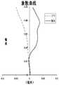
- 2Ashows an axial chromatic aberration curve of the optical imaging system of Embodiment 1, which indicates that the light of different wavelengths is deflected by the focus point after passing through the optical imaging system.
- 2Bshows an astigmatism curve of the optical imaging system of Embodiment 1, which shows meridional field curvature and sagittal image plane curvature.
- 2Cshows a distortion curve of the optical imaging system of Embodiment 1, which represents distortion magnitude values in the case of different viewing angles.
- the optical imaging system given in Embodiment 1can achieve good imaging quality.
- Embodiment 2 of the present applicationis described below with reference to Figs. 3 to 4C.
- the optical imaging system described in the respective embodimentsis the same as the optical imaging system described in Embodiment 1. For the sake of brevity, a description similar to that of Embodiment 1 will be omitted.
- FIG. 3is a block diagram showing the structure of an optical imaging system according to Embodiment 2 of the present application.
- the optical imaging system according to Embodiment 2includes four lenses E1-E4 which are sequentially arranged from the object side to the imaging side along the optical axis.
- the first lens E1has a first transmission surface S1-1, a first reflection surface S2-1, a second reflection surface S1-2, and a second transmission surface S2-2.
- the first transmitting surface S1-1is disposed on the outer circumference of the side surface of the first lens E1; the first reflecting surface S2-1 is disposed on the outer circumference of the image side surface of the first lens E1; and the second reflecting surface S1-2 is disposed on the first surface A paraxial portion of a side surface of the lens E1; and a second transmitting surface S2-2 is disposed at a paraxial shape of the image side surface of the first lens E1.
- the second lens E2has an object side surface S3 and an image side surface S4.
- the third lens E3has an object side surface S5 and an image side surface S6.
- the fourth lens E4has an object side surface S7 and an image side surface S8.
- the first lens E1has a positive power
- the second lens E2has a negative power
- the third lens E3has a positive power
- the fourth lens E4has a positive power
- an aperture STO disposed between the object side and the first lens for limiting the light beamis further included.
- the optical imaging system according to Embodiment 1may include a filter and/or a protective lens.
- a filtercan be used to correct the color deviation
- a protective lenscan be used to protect the image sensing chip located on the imaging surface S9. Light from the object sequentially passes through the respective surfaces S1-1 to S8 and is finally imaged on the imaging plane S9.
- Table 4 belowshows the surface type, radius of curvature, thickness, material, and conical coefficient of each lens of the optical imaging system of Example 2.
- Table 5shows the high order term coefficients of the respective aspherical mirrors in Example 2.
- Table 6shows the effective focal lengths f1 to f4 of the lenses of Embodiment 2, the effective focal length f of the optical imaging system, and the second reflecting surface S1-2 of the first lens E1 to the imaging surface S9 of the optical imaging system on the optical axis.
- the distance TTLcan be defined by the formula (1) given in the above embodiment 1.
- 4Ashows an axial chromatic aberration curve of the optical imaging system of Embodiment 2, which shows that the light of different wavelengths deviates from the focus point after passing through the optical imaging system.
- 4Bshows an astigmatism curve of the optical imaging system of Embodiment 2, which shows meridional field curvature and sagittal image plane curvature.
- 4Cshows a distortion curve of the optical imaging system of Embodiment 2, which represents the distortion magnitude value in the case of different viewing angles.
- the optical imaging system given in Embodiment 2can achieve good imaging quality.
- FIG. 5is a block diagram showing the structure of an optical imaging system according to Embodiment 3 of the present application.
- the optical imaging system according to Embodiment 3includes three lenses E1-E3 which are sequentially arranged from the object side to the imaging side along the optical axis.
- the first lens E1has a first transmission surface S1-1, a first reflection surface S2-1, a second reflection surface S1-2, and a second transmission surface S2-2.
- the first transmitting surface S1-1is disposed on the outer circumference of the side surface of the first lens E1; the first reflecting surface S2-1 is disposed on the outer circumference of the image side surface of the first lens E1; and the second reflecting surface S1-2 is disposed on the first surface A paraxial portion of a side surface of the lens E1; and a second transmitting surface S2-2 is disposed at a paraxial shape of the image side surface of the first lens E1.
- the second lens E2has an object side surface S3 and an image side surface S4.
- the third lens E3has an object side surface S5 and an image side surface S6.
- the first lens E1has a positive power
- the second lens E2has a positive power
- the third lens E3has a negative power
- an aperture STO disposed between the object side and the first lens for limiting the light beamis further included.
- the optical imaging system according to Embodiment 1may include a filter and/or a protective lens.
- a filtercan be used to correct the color deviation
- a protective lenscan be used to protect the image sensing chip located on the imaging surface S7. Light from the object sequentially passes through the respective surfaces S1-1 to S6 and is finally imaged on the imaging plane S7.
- Table 7 belowshows the surface type, radius of curvature, thickness, material, and conical coefficient of each lens of the optical imaging system of Example 3.
- Table 8shows the high order term coefficients of the respective aspherical mirrors in the third embodiment.
- Table 9shows the effective focal lengths f1 to f3 of the lenses of Embodiment 3, the effective focal length f of the optical imaging system, and the second reflecting surface S1-2 of the first lens E1 to the imaging plane S7 of the optical imaging system on the optical axis.
- the distance TTLcan be defined by the formula (1) given in the above embodiment 1.
- FIG. 6Ashows an axial chromatic aberration curve of the optical imaging system of Embodiment 3, which shows that the light of different wavelengths deviates from the focus point after passing through the optical imaging system.
- Fig. 6Bshows an astigmatism curve of the optical imaging system of Embodiment 3, which shows meridional field curvature and sagittal image plane curvature.
- Fig. 6Cshows a distortion curve of the optical imaging system of Embodiment 3, which shows distortion magnitude values in the case of different viewing angles. 6A to 6C, the optical imaging system given in Embodiment 3 can achieve good imaging quality.
- Embodiments 1 to 3respectively satisfy the relationships shown in Table 10 below.
Landscapes
- Physics & Mathematics (AREA)
- General Physics & Mathematics (AREA)
- Optics & Photonics (AREA)
- Lenses (AREA)
Abstract
Description
Translated fromChinese相关申请的交叉引用Cross-reference to related applications
本申请要求于2017年09月21日提交于中国国家知识产权局(SIPO)的、专利申请号为201710859728.3和201721216307.0的两个中国专利申请的优先权和权益,这两个中国专利申请通过引用整体并入本文。This application claims the priority and rights of two Chinese patent applications filed on September 21, 2017 in China National Intellectual Property Office (SIPO), patent application numbers 201710859728.3 and 201721216307.0, which are cited by reference to the entire Chinese patent application. Incorporated herein.
本申请涉及一种光学成像系统,更具体地,涉及折反射光路的光学成像系统。The present application relates to an optical imaging system and, more particularly, to an optical imaging system that deflects the optical path.
目前,光学系统常用的感光元件有电耦合器件(charge-coupled device,CCD)及互补式金属氧化物半导体(complementary metal-oxide semiconductor,CMOS)图像传感器,随着其性能的提高及尺寸减小,对摄像镜头的要求也不断提升。At present, the photosensitive elements commonly used in optical systems include a charge-coupled device (CCD) and a complementary metal-oxide semiconductor (CMOS) image sensor, and as performance and size decrease, The requirements for the camera lens are also constantly increasing.
为了匹配感光元件,需要使光学镜头的总体长度进一步减小,满足小型化和轻量化的要求。但目前配置有折射光学系统、反射光学系统和成像光学系统的摄像系统,都无法满足小型化的要求,难以与不断趋于小型化的成像装置相匹配。In order to match the photosensitive element, it is necessary to further reduce the overall length of the optical lens to meet the requirements of miniaturization and weight reduction. However, currently, an imaging system equipped with a refractive optical system, a reflective optical system, and an imaging optical system cannot meet the requirements of miniaturization, and it is difficult to match an imaging device that is becoming increasingly compact.
因此,本发明旨在提供一种满足小型化,亦能有效改善像差,具有高性能的光学成像系统。Accordingly, the present invention is directed to an optical imaging system having high performance that satisfies miniaturization and can effectively improve aberrations.
发明内容Summary of the invention
本申请提供的技术方案至少部分地解决了以上所述的技术问题。The technical solution provided by the present application at least partially solves the technical problems described above.
根据本申请的一个方面,提供了这样一种光学成像系统,沿着光轴由物侧至像侧依序可包括第一透镜、第二透镜和至少一个后续透镜, 其中,第一透镜可具有:设置于第一透镜物侧面的外圆周的第一透射面;设置于第一透镜像侧面的外圆周的第一反射面;设置于第一透镜物侧面的近轴处的第二反射面;以及设置于第一透镜像侧面的近轴处的第二透射面,其中,光学成像系统的第一透镜的物侧面中心至光学成像系统的成像面在光轴上的距离TTL与光学成像系统的有效焦距f之间可满足:TTL/f≤0.6。According to an aspect of the present application, there is provided an optical imaging system that may sequentially include a first lens, a second lens, and at least one subsequent lens from an object side to an image side along an optical axis, wherein the first lens may have a first transmitting surface disposed on an outer circumference of a side surface of the first lens; a first reflecting surface disposed on an outer circumference of the side of the first lens image; and a second reflecting surface disposed at a paraxial side of the side surface of the first lens; And a second transmissive surface disposed at a paraxial axis of the side of the first lens image, wherein a distance TTL of the object side center of the first lens of the optical imaging system to the imaging plane of the optical imaging system on the optical axis and the optical imaging system The effective focal length f can be satisfied: TTL / f ≤ 0.6.
根据本申请的另一方面,还提供了这样一种光学成像系统,沿着光轴由物侧至像侧依序可包括第一透镜、第二透镜和至少一个后续透镜,其中,第一透镜可具有:设置于第一透镜物侧面的外圆周的第一透射面;设置于第一透镜像侧面的外圆周的第一反射面;设置于第一透镜物侧面的近轴处的第二反射面;以及设置于第一透镜像侧面的近轴处的第二透射面,其中,第一透镜的最大有效半径DT1与光学成像系统的成像面上有效像素区域对角线长的一半ImgH之间满足:DT1/ImgH<2.0。According to another aspect of the present application, there is also provided an optical imaging system comprising, in order from the object side to the image side along the optical axis, a first lens, a second lens and at least one subsequent lens, wherein the first lens The first transmissive surface disposed on an outer circumference of a side surface of the first lens; the first reflection surface disposed on an outer circumference of the side of the first lens image; and the second reflection disposed at a paraxial side of the side surface of the first lens And a second transmissive surface disposed at a paraxial axis of the side of the first lens image, wherein a maximum effective radius DT1 of the first lens is between half of the diagonal length of the effective pixel region on the imaging surface of the optical imaging system, ImgH Satisfied: DT1/ImgH<2.0.
根据本申请的另一方面,还提供了这样一种光学成像系统,沿着光轴由物侧至像侧依序可包括第一透镜、第二透镜和至少一个后续透镜,其中,第一透镜可具有:设置于第一透镜物侧面的外圆周的第一透射面;设置于第一透镜像侧面的外圆周的第一反射面;设置于第一透镜物侧面的近轴处的第二反射面;以及设置于第一透镜像侧面的近轴处的第二透射面,其中,第一透镜的最大有效半径DT1可满足:DT1<4.5mm。According to another aspect of the present application, there is also provided an optical imaging system comprising, in order from the object side to the image side along the optical axis, a first lens, a second lens and at least one subsequent lens, wherein the first lens The first transmissive surface disposed on an outer circumference of a side surface of the first lens; the first reflection surface disposed on an outer circumference of the side of the first lens image; and the second reflection disposed at a paraxial side of the side surface of the first lens And a second transmissive surface disposed at a paraxial shape of the side of the first lens image, wherein the maximum effective radius DT1 of the first lens satisfies: DT1 < 4.5 mm.
根据本申请的另一方面,还提供了这样一种光学成像系统,沿着光轴由物侧至像侧依序可包括第一透镜、第二透镜和至少一个后续透镜,其中,第一透镜可具有:设置于第一透镜物侧面的外圆周的第一透射面;设置于第一透镜像侧面的外圆周的第一反射面;设置于第一透镜物侧面的近轴处的第二反射面;以及设置于第一透镜像侧面的近轴处的第二透射面,其中,可满足:0.1<BFL/TTL<0.2,BFL为最靠近光学成像系统的像侧的透镜的像侧面至光学成像系统的成像面在光轴上的距离;TTL为光学成像系统的第一透镜的物侧面中心至光学成像系统的成像面在光轴上的距离。According to another aspect of the present application, there is also provided an optical imaging system comprising, in order from the object side to the image side along the optical axis, a first lens, a second lens and at least one subsequent lens, wherein the first lens The first transmissive surface disposed on an outer circumference of a side surface of the first lens; the first reflection surface disposed on an outer circumference of the side of the first lens image; and the second reflection disposed at a paraxial side of the side surface of the first lens And a second transmissive surface disposed at a paraxial axis of the side of the first lens image, wherein: 0.1<BFL/TTL<0.2, BFL is the image side of the lens closest to the image side of the optical imaging system to the optical The distance of the imaging plane of the imaging system on the optical axis; TTL is the distance from the center of the object side of the first lens of the optical imaging system to the imaging plane of the optical imaging system on the optical axis.
根据本申请的另一方面,还提供了这样一种光学成像系统,沿着光轴由物侧至像侧依序可包括第一透镜、第二透镜和至少一个后续透镜,其中,第一透镜可具有:设置于第一透镜物侧面的外圆周的第一透射面;设置于第一透镜像侧面的外圆周的第一反射面;设置于第一透镜物侧面的近轴处的第二反射面;以及设置于第一透镜像侧面的近轴处的第二透射面,其中,第一反射面和第二反射面可具有全反射作用。According to another aspect of the present application, there is also provided an optical imaging system comprising, in order from the object side to the image side along the optical axis, a first lens, a second lens and at least one subsequent lens, wherein the first lens The first transmissive surface disposed on an outer circumference of a side surface of the first lens; the first reflection surface disposed on an outer circumference of the side of the first lens image; and the second reflection disposed at a paraxial side of the side surface of the first lens And a second transmissive surface disposed at a paraxial shape of the side of the first lens image, wherein the first reflective surface and the second reflective surface may have a total reflection effect.
在一个实施方式中,第一透镜的最大有效半径DT1可满足:DT1<4.5mm,例如,DT1≤3.5。In one embodiment, the maximum effective radius DT1 of the first lens may satisfy: DT1 < 4.5 mm, for example, DT1 ≤ 3.5.
在一个实施方式中,第一透镜的最大有效半径DT1与光学成像系统的成像面上有效像素区域对角线长的一半ImgH之间可满足:DT1/ImgH<2.0,例如,DT1/ImgH≤1.3。In one embodiment, the maximum effective radius DT1 of the first lens and the half of the diagonal length of the effective pixel area on the imaging surface of the optical imaging system, ImgH, may satisfy: DT1/ImgH<2.0, for example, DT1/ImgH≤1.3 .
在一个实施方式中,第一透镜的最大有效半径DT1与第一透镜的第二透射面的最大有效半径DT2之间可满足:0<DT2/DT1≤0.5,例如,0.3≤DT2/DT1≤0.48。In one embodiment, the maximum effective radius DT1 of the first lens and the maximum effective radius DT2 of the second transmission surface of the first lens may satisfy: 0<DT2/DT1≤0.5, for example, 0.3≤DT2/DT1≤0.48 .
在一个实施方式中,光学成像系统的第一透镜的物侧面中心至光学成像系统的成像面在光轴上的距离TTL与光学成像系统的有效焦距f之间可满足:TTL/f≤0.6。In one embodiment, the distance between the object side center of the first lens of the optical imaging system and the imaging surface of the optical imaging system on the optical axis and the effective focal length f of the optical imaging system may be: TTL / f < 0.6.
在一个实施方式中,光学成像系统的有效焦距f与光学成像系统的入瞳直径EPD之间可满足:f/EPD<2.8,例如,f/EPD≤2.6。In one embodiment, the effective focal length f of the optical imaging system and the entrance pupil diameter EPD of the optical imaging system may satisfy: f/EPD < 2.8, eg, f/EPD < 2.6.
在一个实施方式中,可满足:0.1<BFL/TTL<0.2,例如,0.12≤BFL/TTL≤0.18。其中,BFL为最靠近光学成像系统的像侧的透镜的像侧面至光学成像系统的成像面在光轴上的距离;TTL为光学成像系统的第一透镜的物侧面中心至光学成像系统的成像面在光轴上的距离。In one embodiment, it may be satisfied that: 0.1 < BFL / TTL < 0.2, for example, 0.12 ≤ BFL / TTL ≤ 0.18. Wherein, the BFL is the distance from the image side of the lens closest to the image side of the optical imaging system to the imaging plane of the optical imaging system on the optical axis; the TTL is the imaging of the optical lens imaging system from the center of the object side of the first lens of the optical imaging system The distance on the optical axis.
在一个实施方式中,第一反射面和第二反射面可具有全反射作用。In one embodiment, the first reflective surface and the second reflective surface may have a total reflection effect.
通过上述配置的光学成像系统,还可进一步具有小型化、高性能、高成像品质、高分辨率、平衡像差等至少一个有益效果。With the optical imaging system configured as described above, at least one advantageous effect of miniaturization, high performance, high image quality, high resolution, balance aberration, and the like can be further achieved.
通过参照以下附图所作出的详细描述,本申请的实施方式的以上及其它优点将变得显而易见,附图旨在示出本申请的示例性实施方式而非对其进行限制。在附图中:The above and other advantages of the embodiments of the present invention will be apparent from the description of the appended claims. In the drawing:
图1为示出根据本申请实施例1的光学成像系统的结构示意图;1 is a schematic structural view showing an optical imaging system according to
图2A示出了实施例1的光学成像系统的轴上色差曲线;2A shows an axial chromatic aberration curve of the optical imaging system of
图2B示出了实施例1的光学成像系统的象散曲线;2B shows an astigmatism curve of the optical imaging system of
图2C示出了实施例1的光学成像系统的畸变曲线;2C shows a distortion curve of the optical imaging system of
图3为示出根据本申请实施例2的光学成像系统的结构示意图;3 is a schematic structural view showing an optical imaging system according to Embodiment 2 of the present application;
图4A示出了实施例2的光学成像系统的轴上色差曲线;4A shows an axial chromatic aberration curve of the optical imaging system of Embodiment 2;
图4B示出了实施例2的光学成像系统的象散曲线;4B shows an astigmatism curve of the optical imaging system of Embodiment 2;
图4C示出了实施例2的光学成像系统的畸变曲线;4C shows a distortion curve of the optical imaging system of Embodiment 2;
图5为示出根据本申请实施例3的光学成像系统的结构示意图;FIG. 5 is a schematic structural view showing an optical imaging system according to
图6A示出了实施例3的光学成像系统的轴上色差曲线;6A shows an axial chromatic aberration curve of the optical imaging system of
图6B示出了实施例3的光学成像系统的象散曲线;以及6B shows an astigmatism curve of the optical imaging system of
图6C示出了实施例3的光学成像系统的畸变曲线。FIG. 6C shows a distortion curve of the optical imaging system of
为了更好地理解本申请,将参考附图对本申请的各个方面做出更详细的说明。应理解,这些详细说明只是对本申请的示例性实施方式的描述,而非以任何方式限制本申请的范围。在说明书全文中,相同的附图标号指代相同的元件。表述“和/或”包括相关联的所列项目中的一个或多个的任何和全部组合。For a better understanding of the present application, various aspects of the present application will be described in more detail with reference to the accompanying drawings. It should be understood that the detailed description is only illustrative of the exemplary embodiments of the application, and is not intended to limit the scope of the application. Throughout the specification, the same drawing reference numerals refer to the same elements. The expression "and/or" includes any and all combinations of one or more of the associated listed items.
应注意,在本说明书中,第一、第二等的表述仅用于将一个特征与另一个特征区分开来,而不表示对特征的任何限制。因此,在不背离本申请的教导的情况下,下文中讨论的第一透镜也可被称作第二透镜。It should be noted that in the present specification, the expressions of the first, second, etc. are used to distinguish one feature from another, and do not represent any limitation of the feature. Thus, the first lens discussed below may also be referred to as a second lens without departing from the teachings of the present application.
在附图中,为了便于说明,已稍微夸大了透镜的厚度、尺寸和形状。具体来讲,附图中所示的球面或非球面的形状通过示例的方式示出。即, 球面或非球面的形状不限于附图中示出的球面或非球面的形状。附图仅为示例而并非严格按比例绘制。In the drawings, the thickness, size, and shape of the lens have been somewhat exaggerated for convenience of explanation. Specifically, the spherical or aspherical shape shown in the drawings is shown by way of example. That is, the shape of the spherical surface or the aspherical surface is not limited to the spherical or aspherical shape shown in the drawings. The drawings are only examples and are not to scale.
还应理解的是,用语“包括”、“包括有”、“具有”、“包含”和/或“包含有”,当在本说明书中使用时表示存在所陈述的特征、整体、步骤、操作、元件和/或部件,但不排除存在或附加有一个或多个其它特征、整体、步骤、操作、元件、部件和/或它们的组合。此外,当诸如“...中的至少一个”的表述出现在所列特征的列表之后时,修饰整个所列特征,而不是修饰列表中的单独元件。此外,当描述本申请的实施方式时,使用“可以”表示“本申请的一个或多个实施方式”。并且,用语“示例性的”旨在指代示例或举例说明。It is also to be understood that the terms "comprises", "including", "having", "includes", and "includes", when used in the specification, means that there are the stated features, integers, steps, and operations. The elements, components, and/or components, but do not exclude the presence or addition of one or more other features, integers, steps, operations, components, components and/or combinations thereof. Moreover, when an expression such as "at least one of" appears after the list of listed features, the entire listed features are modified instead of the individual elements in the list. Further, when describing an embodiment of the present application, "may" is used to mean "one or more embodiments of the present application." Also, the term "exemplary" is intended to mean an example or an illustration.
如在本文中使用的,用语“基本上”、“大约”以及类似的用语用作表近似的用语,而不用作表程度的用语,并且旨在说明将由本领域普通技术人员认识到的、测量值或计算值中的固有偏差。As used herein, the terms "substantially", "about", and the like are used as terms of a table approximation, and are not intended to be used as a list of terms, and are intended to illustrate measurement that will be recognized by those of ordinary skill in the art. The inherent deviation in the value or calculated value.
除非另外限定,否则本文中使用的所有用语(包括技术用语和科学用语)均具有与本申请所属领域普通技术人员的通常理解相同的含义。还应理解的是,用语(例如在常用词典中定义的用语)应被解释为具有与它们在相关技术的上下文中的含义一致的含义,并且将不被以理想化或过度正式意义解释,除非本文中明确如此限定。All terms (including technical and scientific terms) used herein have the same meaning as commonly understood by one of ordinary skill in the art to which this invention belongs, unless otherwise defined. It should also be understood that terms (such as terms defined in commonly used dictionaries) should be interpreted as having meaning consistent with their meaning in the context of the related art, and will not be interpreted in an idealized or overly formal sense unless This is clearly defined in this article.
此外,近轴区域是指光轴附近的区域。第一透镜是最靠近物体的透镜。在本文中,每个透镜中最靠近物体的表面称为物侧面,每个透镜中最靠近成像面的表面称为像侧面。Further, the paraxial region refers to a region near the optical axis. The first lens is the lens closest to the object. Herein, the surface closest to the object in each lens is referred to as the object side, and the surface of each lens closest to the image plane is referred to as the image side.
需要说明的是,在不冲突的情况下,本申请中的实施例及实施例中的特征可以相互组合。下面将参考附图并结合实施例来详细说明本申请。It should be noted that the embodiments in the present application and the features in the embodiments may be combined with each other without conflict. The present application will be described in detail below with reference to the accompanying drawings.
以下结合具体实施例进一步描述本申请。The present application is further described below in conjunction with specific embodiments.
根据本申请示例性实施方式的光学成像系统可具有至少三个透镜。例如,在示例性实施方式中,该光学成像系统可包括第一透镜、第二透镜、第三透镜和第四透镜。在另一示例性实施方式中,该光学成像系统可包括第一透镜、第二透镜和第三透镜。这至少三个透镜沿着光轴从物侧至像侧依序排列。An optical imaging system according to an exemplary embodiment of the present application may have at least three lenses. For example, in an exemplary embodiment, the optical imaging system can include a first lens, a second lens, a third lens, and a fourth lens. In another exemplary embodiment, the optical imaging system can include a first lens, a second lens, and a third lens. The at least three lenses are sequentially arranged from the object side to the image side along the optical axis.
在示例性实施方式中,该光学成像系统中的第一透镜可具有设置于第一透镜物侧面的外圆周的第一透射面;设置于第一透镜像侧面的外圆周的第一反射面;设置于第一透镜物侧面的近轴处的第二反射面;以及设置于第一透镜像侧面的近轴处的第二透射面。为光学系统配置折反射光路,可有效降低光学系统的总长,同时最小限度的引入系统球差,从而提升系统性能。In an exemplary embodiment, the first lens in the optical imaging system may have a first transmitting surface disposed on an outer circumference of a side of the first lens; a first reflecting surface disposed on an outer circumference of a side of the first lens image; a second reflecting surface disposed at a paraxial edge of the side of the first lens; and a second transmitting surface disposed at a paraxial axis of the side of the first lens image. By configuring the optical system with a catadioptric optical path, the total length of the optical system can be effectively reduced, and the system spherical aberration can be minimized, thereby improving system performance.
在示例性实施方式中,第一透镜的最大有效半径DT1可满足:DT1<4.5mm,更具体地,可进一步满足DT1≤3.5。通过这样的配置,可降低光学系统口径,满足小型化要求。In an exemplary embodiment, the maximum effective radius DT1 of the first lens may satisfy: DT1 < 4.5 mm, and more specifically, DT1 ≤ 3.5 may be further satisfied. With such a configuration, the aperture of the optical system can be reduced to meet the miniaturization requirements.
在一个实施方式中,第一透镜的最大有效半径DT1与光学成像系统的成像面上有效像素区域对角线长的一半ImgH之间可满足:DT1/ImgH<2.0,更具体地,可进一步满足DT1/ImgH≤1.3。通过这样的配置,在满足口径小型化的基础上,尽可能的提升系统分辨率。In one embodiment, the maximum effective radius DT1 of the first lens and the half ImgH of the diagonal length of the effective pixel area on the imaging surface of the optical imaging system may satisfy: DT1/ImgH<2.0, and more specifically, may further satisfy DT1/ImgH ≤ 1.3. With such a configuration, the system resolution can be improved as much as possible while satisfying the miniaturization of the aperture.
在一个实施方式中,第一透镜的最大有效半径DT1与第一透镜的第二透射面的最大有效半径DT2之间可满足:0<DT2/DT1≤0.5,更具体地,可进一步满足0.3≤DT2/DT1≤0.48。通过这样的配置,可有效提升光学系统的衍射极限,提高系统性能。In one embodiment, the maximum effective radius DT1 of the first lens and the maximum effective radius DT2 of the second transmitting surface of the first lens may satisfy: 0<DT2/DT1≤0.5, and more specifically, may further satisfy 0.3≤ DT2/DT1 ≤ 0.48. With such a configuration, the diffraction limit of the optical system can be effectively improved, and the system performance can be improved.
在一个实施方式中,光学成像系统的第一透镜的物侧面中心至光学成像系统的成像面在光轴上的距离TTL与光学成像系统的有效焦距f之间可满足:TTL/f≤0.6,更具体地,可进一步满足TTL/f≤0.5。通过这样的配置,可实现光学系统的小型化。In one embodiment, the distance between the object side center of the first lens of the optical imaging system and the imaging surface of the optical imaging system on the optical axis and the effective focal length f of the optical imaging system can be: TTL / f ≤ 0.6, More specifically, TTL/f ≤ 0.5 can be further satisfied. With such a configuration, miniaturization of the optical system can be achieved.
在一个实施方式中,光学成像系统的有效焦距f与光学成像系统的入瞳直径EPD之间可满足:f/EPD<2.8,更具体地,可进一步满足f/EPD≤2.6。通过这样的配置,可保证光学系统的通光量,进而提升系统的衍射极限。In one embodiment, the effective focal length f of the optical imaging system and the entrance pupil diameter EPD of the optical imaging system may satisfy: f/EPD < 2.8, and more specifically, f/EPD ≤ 2.6 may be further satisfied. With such a configuration, the amount of light passing through the optical system can be ensured, thereby increasing the diffraction limit of the system.
在一个实施方式中,可满足:0.1<BFL/TTL<0.2,更具体地,可进一步满足0.12≤BFL/TTL≤0.18。其中,BFL为最靠近光学成像系统的像侧的透镜的像侧面至光学成像系统的成像面在光轴上的距离;TTL为光学成像系统的第一透镜的物侧面中心至光学成像系统的成像面在光轴上的距离。通过这样的配置,可保证光学系统后焦的取值范 围,以满足系统小型化要求,同时满足系统实际生产装配的要求。In one embodiment, 0.1 < BFL / TTL < 0.2 may be satisfied, and more specifically, 0.12 ≤ BFL / TTL ≤ 0.18 may be further satisfied. Wherein, the BFL is the distance from the image side of the lens closest to the image side of the optical imaging system to the imaging plane of the optical imaging system on the optical axis; the TTL is the imaging of the optical lens imaging system from the center of the object side of the first lens of the optical imaging system The distance on the optical axis. With such a configuration, the range of the back focus of the optical system can be ensured to meet the system miniaturization requirements while meeting the requirements of the actual production assembly of the system.
在一个实施方式中,第一反射面和第二反射面可具有全反射作用。通过合理选择透镜的折射率范围,可减少像差的产生,从而有效提升光学系统的性能。In one embodiment, the first reflective surface and the second reflective surface may have a total reflection effect. By properly selecting the refractive index range of the lens, the generation of aberrations can be reduced, thereby effectively improving the performance of the optical system.
在示例性实施方式中,光学成像系统还可设置有用于限制光束的光圈STO,调节进光量,提高成像品质。根据本申请的上述实施方式的光学成像系统可采用多片镜片,例如上文所述的三片、四片等。通过引入折反射光路,合理分配各透镜的光焦度、面型、各透镜的中心厚度以及各透镜之间的轴上间距等,可保证镜头的小型化并改善像差,提高成像质量,从而使得光学成像系统更有利于生产加工并且可适用于便携式电子产品。In an exemplary embodiment, the optical imaging system may also be provided with an aperture STO for limiting the beam, adjusting the amount of incoming light, and improving imaging quality. The optical imaging system according to the above-described embodiments of the present application may employ a plurality of lenses, such as three, four, and the like as described above. By introducing a deflected light path, the optical power, the surface shape, the center thickness of each lens, and the on-axis spacing between the lenses are properly distributed, thereby ensuring miniaturization of the lens, improving aberrations, and improving image quality. The optical imaging system is made more advantageous for production processing and can be applied to portable electronic products.
在本申请的实施方式中,各透镜的镜面中的至少一个为非球面镜面。非球面透镜的特点是:曲率从透镜中心到周边是连续变化的。与从透镜中心到周边有恒定曲率的球面透镜不同,非球面透镜具有更佳的曲率半径特性,具有改善歪曲像差及改善像散像差的优点,能够使得视野变得更大而真实。采用非球面透镜后,能够尽可能地消除在成像的时候出现的像差,从而改善成像质量。另外,非球面透镜的使用还可有效地减少光学系统中的透镜个数。In an embodiment of the present application, at least one of the mirror faces of each lens is an aspherical mirror. Aspherical lenses are characterized by a continuous change in curvature from the center of the lens to the periphery. Unlike a spherical lens having a constant curvature from the center of the lens to the periphery, the aspherical lens has better curvature radius characteristics, has the advantages of improving distortion and improving astigmatic aberration, and can make the field of view larger and more realistic. With an aspherical lens, the aberrations that occur during imaging can be eliminated as much as possible, improving image quality. In addition, the use of aspherical lenses can also effectively reduce the number of lenses in an optical system.
然而,本领域的技术人员应当理解,在未背离本申请要求保护的技术方案的情况下,可改变构成镜头的透镜数量,来获得本说明书中描述的各个结果和优点。例如,该光学成像系统还可包括其它数量的透镜。However, those skilled in the art will appreciate that the various results and advantages described in this specification can be obtained without varying the number of lenses that make up the lens without departing from the technical solutions claimed herein. For example, the optical imaging system can also include other numbers of lenses.
下面参照附图进一步描述可适用于上述实施方式的光学成像系统的具体实施例。A specific embodiment of an optical imaging system applicable to the above embodiment will be further described below with reference to the accompanying drawings.
实施例1Example 1
以下参照图1至图2C描述根据本申请实施例1的光学成像系统。An optical imaging system according to
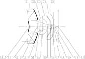
图1示出了根据本申请实施例1的光学成像系统的结构示意图。如图1所示,光学成像系统沿着光轴包括从物侧至成像侧依序排列的 四个透镜E1-E4。FIG. 1 is a block diagram showing the structure of an optical imaging system according to
第一透镜E1具有第一透射面S1-1、第一反射面S2-1、第二反射面S1-2和第二透射面S2-2。其中,第一透射面S1-1设置于第一透镜E1物侧面的外圆周;第一反射面S2-1设置于第一透镜E1像侧面的外圆周;第二反射面S1-2设置于第一透镜E1物侧面的近轴处;以及第二透射面S2-2设置于第一透镜E1像侧面的近轴处。The first lens E1 has a first transmission surface S1-1, a first reflection surface S2-1, a second reflection surface S1-2, and a second transmission surface S2-2. The first transmitting surface S1-1 is disposed on the outer circumference of the side surface of the first lens E1; the first reflecting surface S2-1 is disposed on the outer circumference of the image side surface of the first lens E1; and the second reflecting surface S1-2 is disposed on the first surface A paraxial portion of a side surface of the lens E1; and a second transmitting surface S2-2 is disposed at a paraxial shape of the image side surface of the first lens E1.
第二透镜E2具有物侧面S3和像侧面S4。The second lens E2 has an object side surface S3 and an image side surface S4.
第三透镜E3具有物侧面S5和像侧面S6。The third lens E3 has an object side surface S5 and an image side surface S6.
第四透镜E4具有物侧面S7和像侧面S8。The fourth lens E4 has an object side surface S7 and an image side surface S8.
在该实施例中,第一透镜E1具有正光焦度;第二透镜E2具有正光焦度;第三透镜E3具有负光焦度;以及第四透镜E4具有负光焦度。In this embodiment, the first lens E1 has a positive power; the second lens E2 has a positive power; the third lens E3 has a negative power; and the fourth lens E4 has a negative power.
在本实施例的光学成像系统中,还包括用于限制光束的、设置在物侧与第一透镜之间的光圈STO。In the optical imaging system of the present embodiment, an aperture STO disposed between the object side and the first lens for limiting the light beam is further included.
根据实施例1的光学成像系统可包括具有物侧面S9和像侧面S10的滤光片E5和/或保护透镜E5’。滤光片E5可用于校正色彩偏差,保护透镜E5’可用于保护位于成像面S11的图像传感芯片。来自物体的光依序穿过各表面S1-1至S10并最终成像在成像面S11上。The optical imaging system according to
下表1中示出了实施例1的光学成像系统的各透镜的表面类型、曲率半径、厚度、材料及圆锥系数。The surface type, radius of curvature, thickness, material, and conical coefficient of each lens of the optical imaging system of Example 1 are shown in Table 1 below.
表1Table 1


本实施例采用了四片透镜作为示例,通过合理分配各镜片的焦距与面型,有效缩短镜头总长度,保证镜头小型化;同时校正各类像差,提高了镜头的解析度与成像品质。各非球面面型x由以下公式限定:In this embodiment, four lenses are used as an example. By appropriately assigning the focal length and surface shape of each lens, the total length of the lens is effectively shortened, and the lens is miniaturized; at the same time, various aberrations are corrected, and the resolution and imaging quality of the lens are improved. Each aspherical surface type x is defined by the following formula:

其中,x为非球面沿光轴方向在高度为h的位置时,距非球面顶点的距离矢高;c为非球面的近轴曲率,c=1/R(即,近轴曲率c为上表1中曲率半径R的倒数);k为圆锥系数(在上表1中已给出);Ai是非球面第i-th阶的修正系数。下表2示出了实施例1中可用于各镜面S1-1至S8的高次项系数A4、A6、A8、A10、A12、A14、A16和A18。Where x is the position of the aspherical surface at height h in the direction of the optical axis, and the distance from the aspherical vertex is high; c is the paraxial curvature of the aspherical surface, c=1/R (ie, the paraxial curvature c is the above table) 1 is the reciprocal of the radius of curvature R; k is the conic coefficient (given in Table 1 above); Ai is the correction coefficient of the a-th order of the aspheric surface. Table 2 below shows the high order coefficient A4 , A6 , A8 , A10 , A12 , A14 , A16 and A18 which can be used for each of the mirror faces S1-1 to S8 in
表2Table 2
以下表3中示出了实施例1的各透镜的有效焦距f1至f4、光学成像系统的有效焦距f以及第一透镜E1的第二反射面S1-2至光学成像系统的成像面S11在光轴上的距离TTL。The effective focal lengths f1 to f4 of the lenses of
表3table 3
根据表1-表3可得,在该实施例中,第一透镜E1的最大有效半径DT1满足DT1=2.77mm;第一透镜E1的最大有效半径DT1与光学成像系统的成像面上有效像素区域对角线长的一半ImgH之间满足DT1/ImgH=1.01;第一透镜E1的最大有效半径DT1与第一透镜E1的第二透射面S2-2的最大有效半径DT2之间满足DT2/DT1=0.48;光学成像系统的第一透镜E1的第二反射面S1-2中心至光学成像系统的成像面S11在光轴上的距离TTL与光学成像系统的有效焦距f之间满足TTL/f=0.44;光学成像系统的有效焦距f与光学成像系统的入瞳直径EPD之间满足f/EPD=2.3;以及满足BFL/TTL=0.18,其中,BFL为第四透镜E4的像侧面S8至光学成像系统的成像面S11在光轴上的距离;TTL为光学成像系统的第一透镜的第二反射面S1-2中心至光学成像系统的成像面S11在光轴上的距离。According to Table 1 - Table 3, in this embodiment, the maximum effective radius DT1 of the first lens E1 satisfies DT1 = 2.77 mm; the maximum effective radius DT1 of the first lens E1 and the effective pixel area on the imaging surface of the optical imaging system DT1/ImgH=1.01 is satisfied between half of the diagonal length ImgH; DT2/DT1= is satisfied between the maximum effective radius DT1 of the first lens E1 and the maximum effective radius DT2 of the second transmission surface S2-2 of the first lens E1. 0.48; the distance from the center of the second reflecting surface S1-2 of the first lens E1 of the optical imaging system to the imaging surface S11 of the optical imaging system on the optical axis and the effective focal length f of the optical imaging system satisfy TTL/f=0.44 The effective focal length f of the optical imaging system satisfies f/EPD=2.3 between the entrance pupil diameter EPD of the optical imaging system; and BFL/TTL=0.18 is satisfied, wherein the BFL is the image side S8 of the fourth lens E4 to the optical imaging system The distance of the imaging plane S11 on the optical axis; TTL is the distance from the center of the second reflecting surface S1-2 of the first lens of the optical imaging system to the imaging plane S11 of the optical imaging system on the optical axis.
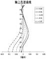
图2A示出了实施例1的光学成像系统的轴上色差曲线,其表示不同波长的光线经由光学成像系统后的会聚焦点偏离。图2B示出了实施例1的光学成像系统的象散曲线,其表示子午像面弯曲和弧矢像面弯曲。图2C示出了实施例1的光学成像系统的畸变曲线,其表示不同视角情况下的畸变大小值。根据图2A至图2C可知,实施例1所给出的光学成像系统能够实现良好的成像品质。2A shows an axial chromatic aberration curve of the optical imaging system of
实施例2Example 2
以下参照图3至图4C描述了根据本申请实施例2的光学成像系 统。除了光学成像系统的各镜片的参数之外,例如除了各镜片的曲率半径、厚度、圆锥系数、有效焦距、轴上间距、各镜面的高次项系数等之外,在本实施例2及以下各实施例中描述的光学成像系统与实施例1中描述的光学成像系统的布置结构相同。为简洁起见,将省略部分与实施例1相似的描述。An optical imaging system according to Embodiment 2 of the present application is described below with reference to Figs. 3 to 4C. In addition to the parameters of the respective lenses of the optical imaging system, for example, in addition to the curvature radius, thickness, conic coefficient, effective focal length, on-axis pitch, high-order coefficient of each mirror surface, etc. of each lens, in the present embodiment 2 and below The optical imaging system described in the respective embodiments is the same as the optical imaging system described in
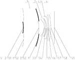
图3示出了根据本申请实施例2的光学成像系统的结构示意图。如图3所示,根据实施例2的光学成像系统包括沿光轴从物侧至成像侧依序排列的四个透镜E1-E4。FIG. 3 is a block diagram showing the structure of an optical imaging system according to Embodiment 2 of the present application. As shown in FIG. 3, the optical imaging system according to Embodiment 2 includes four lenses E1-E4 which are sequentially arranged from the object side to the imaging side along the optical axis.
第一透镜E1具有第一透射面S1-1、第一反射面S2-1、第二反射面S1-2和第二透射面S2-2。其中,第一透射面S1-1设置于第一透镜E1物侧面的外圆周;第一反射面S2-1设置于第一透镜E1像侧面的外圆周;第二反射面S1-2设置于第一透镜E1物侧面的近轴处;以及第二透射面S2-2设置于第一透镜E1像侧面的近轴处。The first lens E1 has a first transmission surface S1-1, a first reflection surface S2-1, a second reflection surface S1-2, and a second transmission surface S2-2. The first transmitting surface S1-1 is disposed on the outer circumference of the side surface of the first lens E1; the first reflecting surface S2-1 is disposed on the outer circumference of the image side surface of the first lens E1; and the second reflecting surface S1-2 is disposed on the first surface A paraxial portion of a side surface of the lens E1; and a second transmitting surface S2-2 is disposed at a paraxial shape of the image side surface of the first lens E1.
第二透镜E2具有物侧面S3和像侧面S4。The second lens E2 has an object side surface S3 and an image side surface S4.
第三透镜E3具有物侧面S5和像侧面S6。The third lens E3 has an object side surface S5 and an image side surface S6.
第四透镜E4具有物侧面S7和像侧面S8。The fourth lens E4 has an object side surface S7 and an image side surface S8.
在该实施例中,第一透镜E1具有正光焦度;第二透镜E2具有负光焦度;第三透镜E3具有正光焦度;;以及第四透镜E4具有正光焦度。In this embodiment, the first lens E1 has a positive power; the second lens E2 has a negative power; the third lens E3 has a positive power; and the fourth lens E4 has a positive power.
在本实施例的光学成像系统中,还包括用于限制光束的、设置在物侧与第一透镜之间的光圈STO。In the optical imaging system of the present embodiment, an aperture STO disposed between the object side and the first lens for limiting the light beam is further included.
根据实施例1的光学成像系统可包括滤光片和/或保护透镜。滤光片可用于校正色彩偏差,保护透镜可用于保护位于成像面S9的图像传感芯片。来自物体的光依序穿过各表面S1-1至S8并最终成像在成像面S9上。The optical imaging system according to
下表4示出了实施例2的光学成像系统的各透镜的表面类型、曲率半径、厚度、材料及圆锥系数。表5示出了实施例2中各非球面镜面的高次项系数。表6示出了实施例2的各透镜的有效焦距f1至f4、光学成像系统的有效焦距f以及第一透镜E1的第二反射面S1-2至光学成像系统的成像面S9在光轴上的距离TTL。其中,各非球面面型 可由上述实施例1中给出的公式(1)限定。Table 4 below shows the surface type, radius of curvature, thickness, material, and conical coefficient of each lens of the optical imaging system of Example 2. Table 5 shows the high order term coefficients of the respective aspherical mirrors in Example 2. Table 6 shows the effective focal lengths f1 to f4 of the lenses of Embodiment 2, the effective focal length f of the optical imaging system, and the second reflecting surface S1-2 of the first lens E1 to the imaging surface S9 of the optical imaging system on the optical axis. The distance TTL. Here, each aspherical surface type can be defined by the formula (1) given in the
表4Table 4

表5table 5
表6Table 6
图4A示出了实施例2的光学成像系统的轴上色差曲线,其表示不同波长的光线经由光学成像系统后的会聚焦点偏离。图4B示出了实施例2的光学成像系统的象散曲线,其表示子午像面弯曲和弧矢像面弯曲。图4C示出了实施例2的光学成像系统的畸变曲线,其表示不同视角情况下的畸变大小值。根据图4A至图4C可知,实施例2所给出的光学成像系统能够实现良好的成像品质。4A shows an axial chromatic aberration curve of the optical imaging system of Embodiment 2, which shows that the light of different wavelengths deviates from the focus point after passing through the optical imaging system. 4B shows an astigmatism curve of the optical imaging system of Embodiment 2, which shows meridional field curvature and sagittal image plane curvature. 4C shows a distortion curve of the optical imaging system of Embodiment 2, which represents the distortion magnitude value in the case of different viewing angles. 4A to 4C, the optical imaging system given in Embodiment 2 can achieve good imaging quality.
实施例3Example 3
以下参照图5至图6C描述了根据本申请实施例3的光学成像系统。An optical imaging system according to
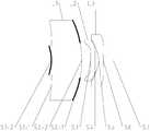
图5示出了根据本申请实施例3的光学成像系统的结构示意图。如图5所示,根据实施例3的光学成像系统包括沿光轴从物侧至成像侧依序排列的三个透镜E1-E3。FIG. 5 is a block diagram showing the structure of an optical imaging system according to
第一透镜E1具有第一透射面S1-1、第一反射面S2-1、第二反射面S1-2和第二透射面S2-2。其中,第一透射面S1-1设置于第一透镜E1物侧面的外圆周;第一反射面S2-1设置于第一透镜E1像侧面的外圆周;第二反射面S1-2设置于第一透镜E1物侧面的近轴处;以及第二透射面S2-2设置于第一透镜E1像侧面的近轴处。The first lens E1 has a first transmission surface S1-1, a first reflection surface S2-1, a second reflection surface S1-2, and a second transmission surface S2-2. The first transmitting surface S1-1 is disposed on the outer circumference of the side surface of the first lens E1; the first reflecting surface S2-1 is disposed on the outer circumference of the image side surface of the first lens E1; and the second reflecting surface S1-2 is disposed on the first surface A paraxial portion of a side surface of the lens E1; and a second transmitting surface S2-2 is disposed at a paraxial shape of the image side surface of the first lens E1.
第二透镜E2具有物侧面S3和像侧面S4。The second lens E2 has an object side surface S3 and an image side surface S4.
第三透镜E3具有物侧面S5和像侧面S6。The third lens E3 has an object side surface S5 and an image side surface S6.
在该实施例中,第一透镜E1具有正光焦度;第二透镜E2具有正光焦度;以及第三透镜E3具有负光焦度。In this embodiment, the first lens E1 has a positive power; the second lens E2 has a positive power; and the third lens E3 has a negative power.
在本实施例的光学成像系统中,还包括用于限制光束的、设置在物侧与第一透镜之间的光圈STO。In the optical imaging system of the present embodiment, an aperture STO disposed between the object side and the first lens for limiting the light beam is further included.
根据实施例1的光学成像系统可包括滤光片和/或保护透镜。滤光片可用于校正色彩偏差,保护透镜可用于保护位于成像面S7的图像传 感芯片。来自物体的光依序穿过各表面S1-1至S6并最终成像在成像面S7上。The optical imaging system according to
下表7示出了实施例3的光学成像系统的各透镜的表面类型、曲率半径、厚度、材料及圆锥系数。表8示出了实施例3中各非球面镜面的高次项系数。表9示出了实施例3的各透镜的有效焦距f1至f3、光学成像系统的有效焦距f以及第一透镜E1的第二反射面S1-2至光学成像系统的成像面S7在光轴上的距离TTL。其中,各非球面面型可由上述实施例1中给出的公式(1)限定。Table 7 below shows the surface type, radius of curvature, thickness, material, and conical coefficient of each lens of the optical imaging system of Example 3. Table 8 shows the high order term coefficients of the respective aspherical mirrors in the third embodiment. Table 9 shows the effective focal lengths f1 to f3 of the lenses of
表7Table 7

表8Table 8
表9Table 9
图6A示出了实施例3的光学成像系统的轴上色差曲线,其表示不同波长的光线经由光学成像系统后的会聚焦点偏离。图6B示出了实施例3的光学成像系统的象散曲线,其表示子午像面弯曲和弧矢像面弯曲。图6C示出了实施例3的光学成像系统的畸变曲线,其表示不同视角情况下的畸变大小值。根据图6A至图6C可知,实施例3所给出的光学成像系统能够实现良好的成像品质。6A shows an axial chromatic aberration curve of the optical imaging system of
综上,实施例1至实施例3分别满足以下表10所示的关系。In summary,
表10Table 10
以上描述仅为本申请的较佳实施例以及对所运用技术原理的说明。本领域技术人员应当理解,本申请中所涉及的发明范围,并不限于上述技术特征的特定组合而成的技术方案,同时也应涵盖在不脱离所述发明构思的情况下,由上述技术特征或其等同特征进行任意组合而形成的其它技术方案。例如上述特征与本申请中公开的(但不限于)具有类似功能的技术特征进行互相替换而形成的技术方案。The above description is only a preferred embodiment of the present application and a description of the principles of the applied technology. It should be understood by those skilled in the art that the scope of the invention referred to in the present application is not limited to the specific combination of the above technical features, and should also be covered by the above technical features without departing from the inventive concept. Other technical solutions formed by any combination of their equivalent features. For example, the above features are combined with the technical features disclosed in the present application, but are not limited to the technical features having similar functions.
Claims (14)
Translated fromChinesePriority Applications (1)
| Application Number | Priority Date | Filing Date | Title |
|---|---|---|---|
| US16/273,940US10996449B2 (en) | 2017-09-21 | 2019-02-12 | Optical imaging system |
Applications Claiming Priority (4)
| Application Number | Priority Date | Filing Date | Title |
|---|---|---|---|
| CN201721216307.0 | 2017-09-21 | ||
| CN201710859728.3ACN107436485B (en) | 2017-09-21 | 2017-09-21 | Optical imaging system |
| CN201721216307.0UCN207148403U (en) | 2017-09-21 | 2017-09-21 | Optical imaging system |
| CN201710859728.3 | 2017-09-21 |
Related Child Applications (1)
| Application Number | Title | Priority Date | Filing Date |
|---|---|---|---|
| US16/273,940ContinuationUS10996449B2 (en) | 2017-09-21 | 2019-02-12 | Optical imaging system |
Publications (1)
| Publication Number | Publication Date |
|---|---|
| WO2019056817A1true WO2019056817A1 (en) | 2019-03-28 |
Family
ID=65809561
Family Applications (1)
| Application Number | Title | Priority Date | Filing Date |
|---|---|---|---|
| PCT/CN2018/091834CeasedWO2019056817A1 (en) | 2017-09-21 | 2018-06-19 | Optical imaging system |
Country Status (2)
| Country | Link |
|---|---|
| US (1) | US10996449B2 (en) |
| WO (1) | WO2019056817A1 (en) |
Families Citing this family (11)
| Publication number | Priority date | Publication date | Assignee | Title |
|---|---|---|---|---|
| TWI710793B (en)* | 2019-08-23 | 2020-11-21 | 大立光電股份有限公司 | Optical photographing system and electronic device |
| CN110646932B (en) | 2019-09-27 | 2022-05-17 | Oppo广东移动通信有限公司 | Reflective camera and electronic device |
| CN110927940B (en)* | 2019-12-19 | 2022-02-08 | 浙江舜宇光学有限公司 | Image pickup apparatus |
| CN113740999B (en)* | 2020-05-29 | 2023-02-10 | 华为技术有限公司 | Optical lenses, lens modules and electronic equipment |
| JP7051940B2 (en)* | 2020-06-23 | 2022-04-11 | エーエーシー オプティックス ソリューションズ ピーティーイー リミテッド | Imaging lens of catadioptric system |
| KR102409108B1 (en)* | 2020-09-18 | 2022-06-15 | 삼성전기주식회사 | Optical Imaging System |
| KR102544194B1 (en)* | 2020-11-02 | 2023-06-15 | 삼성전기주식회사 | Optical Imaging System |
| WO2023081071A1 (en)* | 2021-11-03 | 2023-05-11 | SoliDDD Corp. | Flat aperture telephoto lens |
| CN114222036A (en)* | 2021-11-16 | 2022-03-22 | 昆山丘钛微电子科技股份有限公司 | Optical components |
| DE102022114813B3 (en) | 2022-06-13 | 2023-07-06 | Carl Zeiss Ag | Optical arrangement with overview function for catadioptric microscope objective, objective, image acquisition device or image reproduction device and device |
| DE102022114814B3 (en) | 2022-06-13 | 2023-07-27 | Carl Zeiss Ag | Catadioptric optical assembly, lens, imaging device and apparatus |
Citations (8)
| Publication number | Priority date | Publication date | Assignee | Title |
|---|---|---|---|---|
| JP2004258238A (en)* | 2003-02-25 | 2004-09-16 | Nikon Corp | Catadioptric afocal converter |
| CN103309019A (en)* | 2013-06-24 | 2013-09-18 | 中国科学院长春光学精密机械与物理研究所 | Optical system of ultraviolet multi-band panoramic imaging instrument |
| CN203981954U (en)* | 2014-07-18 | 2014-12-03 | 浙江大学 | One utilizes optical thin film to realize refraction-reflection blind-area-free panoramic endless belt imaging system |
| CN106610520A (en)* | 2017-01-19 | 2017-05-03 | 吉林省中业光电技术有限公司 | Internal reflection type catadioptric panoramic imaging lens |
| CN106773034A (en)* | 2017-01-16 | 2017-05-31 | 浙江大学 | The common light path overall view ring belt optical imaging device of active polarization targets improvement |
| CN106873134A (en)* | 2017-01-19 | 2017-06-20 | 吉林省中业光电技术有限公司 | A kind of catadioptric ultra-wide angle imaging system |
| CN107436485A (en)* | 2017-09-21 | 2017-12-05 | 浙江舜宇光学有限公司 | Optical imaging system |
| CN207148403U (en)* | 2017-09-21 | 2018-03-27 | 浙江舜宇光学有限公司 | Optical imaging system |
Family Cites Families (5)
| Publication number | Priority date | Publication date | Assignee | Title |
|---|---|---|---|---|
| US7907356B2 (en) | 2006-04-14 | 2011-03-15 | Konica Minolta Opto, Inc. | Image pickup lens and image pickup apparatus |
| JP5074114B2 (en) | 2007-07-09 | 2012-11-14 | オリンパス株式会社 | Optical element, optical system including the same, and endoscope using the same |
| CN102621666B (en) | 2011-12-27 | 2014-05-14 | 苏州大学 | Telescope objective optical system |
| KR101544792B1 (en)* | 2014-12-30 | 2015-08-18 | 주식회사 세코닉스 | Iris lens system |
| CN107065142B (en) | 2017-05-27 | 2023-03-31 | 浙江舜宇光学有限公司 | Imaging lens group |
- 2018
- 2018-06-19WOPCT/CN2018/091834patent/WO2019056817A1/ennot_activeCeased
- 2019
- 2019-02-12USUS16/273,940patent/US10996449B2/enactiveActive
Patent Citations (8)
| Publication number | Priority date | Publication date | Assignee | Title |
|---|---|---|---|---|
| JP2004258238A (en)* | 2003-02-25 | 2004-09-16 | Nikon Corp | Catadioptric afocal converter |
| CN103309019A (en)* | 2013-06-24 | 2013-09-18 | 中国科学院长春光学精密机械与物理研究所 | Optical system of ultraviolet multi-band panoramic imaging instrument |
| CN203981954U (en)* | 2014-07-18 | 2014-12-03 | 浙江大学 | One utilizes optical thin film to realize refraction-reflection blind-area-free panoramic endless belt imaging system |
| CN106773034A (en)* | 2017-01-16 | 2017-05-31 | 浙江大学 | The common light path overall view ring belt optical imaging device of active polarization targets improvement |
| CN106610520A (en)* | 2017-01-19 | 2017-05-03 | 吉林省中业光电技术有限公司 | Internal reflection type catadioptric panoramic imaging lens |
| CN106873134A (en)* | 2017-01-19 | 2017-06-20 | 吉林省中业光电技术有限公司 | A kind of catadioptric ultra-wide angle imaging system |
| CN107436485A (en)* | 2017-09-21 | 2017-12-05 | 浙江舜宇光学有限公司 | Optical imaging system |
| CN207148403U (en)* | 2017-09-21 | 2018-03-27 | 浙江舜宇光学有限公司 | Optical imaging system |
Also Published As
| Publication number | Publication date |
|---|---|
| US20190187446A1 (en) | 2019-06-20 |
| US10996449B2 (en) | 2021-05-04 |
Similar Documents
| Publication | Publication Date | Title |
|---|---|---|
| CN108445609B (en) | Camera lens group | |
| WO2019056817A1 (en) | Optical imaging system | |
| WO2021008232A1 (en) | Optical imaging lens | |
| WO2019210672A1 (en) | Optical imaging system | |
| WO2019091170A1 (en) | Camera lens set | |
| WO2020007081A1 (en) | Optical imaging lens | |
| CN107436485B (en) | Optical imaging system | |
| WO2019052220A1 (en) | Optical imaging lens | |
| WO2020107936A1 (en) | Optical imaging system | |
| WO2018214349A1 (en) | Camera lens | |
| CN107783258B (en) | projection lens | |
| WO2019037466A1 (en) | Camera lens | |
| WO2019169856A1 (en) | Camera lens set | |
| WO2018218889A1 (en) | Optical imaging system | |
| WO2019184367A1 (en) | Optical system | |
| WO2018209890A1 (en) | Imaging camera lens | |
| WO2018209855A1 (en) | Optical imaging system | |
| WO2019137055A1 (en) | Imaging lens system | |
| WO2019024490A1 (en) | Optical imaging lens | |
| WO2019052145A1 (en) | Photography camera | |
| WO2019019626A1 (en) | Imaging lens | |
| WO2019037420A1 (en) | Camera lens group | |
| WO2019000986A1 (en) | Optical imaging system | |
| WO2019174364A1 (en) | Optical imaging system | |
| WO2019019530A1 (en) | Optical imaging camera |
Legal Events
| Date | Code | Title | Description |
|---|---|---|---|
| 121 | Ep: the epo has been informed by wipo that ep was designated in this application | Ref document number:18858470 Country of ref document:EP Kind code of ref document:A1 | |
| NENP | Non-entry into the national phase | Ref country code:DE | |
| 122 | Ep: pct application non-entry in european phase | Ref document number:18858470 Country of ref document:EP Kind code of ref document:A1 |