WO2019052305A1 - Valve stent and valve prosthesis - Google Patents
Valve stent and valve prosthesisDownload PDFInfo
- Publication number
- WO2019052305A1 WO2019052305A1PCT/CN2018/100917CN2018100917WWO2019052305A1WO 2019052305 A1WO2019052305 A1WO 2019052305A1CN 2018100917 WCN2018100917 WCN 2018100917WWO 2019052305 A1WO2019052305 A1WO 2019052305A1
- Authority
- WO
- WIPO (PCT)
- Prior art keywords
- valve
- channel structure
- end portion
- valve stent
- stent
- Prior art date
- Legal status (The legal status is an assumption and is not a legal conclusion. Google has not performed a legal analysis and makes no representation as to the accuracy of the status listed.)
- Ceased
Links
Images


Classifications
- A—HUMAN NECESSITIES
- A61—MEDICAL OR VETERINARY SCIENCE; HYGIENE
- A61F—FILTERS IMPLANTABLE INTO BLOOD VESSELS; PROSTHESES; DEVICES PROVIDING PATENCY TO, OR PREVENTING COLLAPSING OF, TUBULAR STRUCTURES OF THE BODY, e.g. STENTS; ORTHOPAEDIC, NURSING OR CONTRACEPTIVE DEVICES; FOMENTATION; TREATMENT OR PROTECTION OF EYES OR EARS; BANDAGES, DRESSINGS OR ABSORBENT PADS; FIRST-AID KITS
- A61F2/00—Filters implantable into blood vessels; Prostheses, i.e. artificial substitutes or replacements for parts of the body; Appliances for connecting them with the body; Devices providing patency to, or preventing collapsing of, tubular structures of the body, e.g. stents
- A61F2/02—Prostheses implantable into the body
- A61F2/24—Heart valves ; Vascular valves, e.g. venous valves; Heart implants, e.g. passive devices for improving the function of the native valve or the heart muscle; Transmyocardial revascularisation [TMR] devices; Valves implantable in the body
- A61F2/2412—Heart valves ; Vascular valves, e.g. venous valves; Heart implants, e.g. passive devices for improving the function of the native valve or the heart muscle; Transmyocardial revascularisation [TMR] devices; Valves implantable in the body with soft flexible valve members, e.g. tissue valves shaped like natural valves
- A61F2/2418—Scaffolds therefor, e.g. support stents
- A—HUMAN NECESSITIES
- A61—MEDICAL OR VETERINARY SCIENCE; HYGIENE
- A61F—FILTERS IMPLANTABLE INTO BLOOD VESSELS; PROSTHESES; DEVICES PROVIDING PATENCY TO, OR PREVENTING COLLAPSING OF, TUBULAR STRUCTURES OF THE BODY, e.g. STENTS; ORTHOPAEDIC, NURSING OR CONTRACEPTIVE DEVICES; FOMENTATION; TREATMENT OR PROTECTION OF EYES OR EARS; BANDAGES, DRESSINGS OR ABSORBENT PADS; FIRST-AID KITS
- A61F2/00—Filters implantable into blood vessels; Prostheses, i.e. artificial substitutes or replacements for parts of the body; Appliances for connecting them with the body; Devices providing patency to, or preventing collapsing of, tubular structures of the body, e.g. stents
- A61F2/02—Prostheses implantable into the body
- A61F2/24—Heart valves ; Vascular valves, e.g. venous valves; Heart implants, e.g. passive devices for improving the function of the native valve or the heart muscle; Transmyocardial revascularisation [TMR] devices; Valves implantable in the body
- A61F2/2409—Support rings therefor, e.g. for connecting valves to tissue
- A—HUMAN NECESSITIES
- A61—MEDICAL OR VETERINARY SCIENCE; HYGIENE
- A61F—FILTERS IMPLANTABLE INTO BLOOD VESSELS; PROSTHESES; DEVICES PROVIDING PATENCY TO, OR PREVENTING COLLAPSING OF, TUBULAR STRUCTURES OF THE BODY, e.g. STENTS; ORTHOPAEDIC, NURSING OR CONTRACEPTIVE DEVICES; FOMENTATION; TREATMENT OR PROTECTION OF EYES OR EARS; BANDAGES, DRESSINGS OR ABSORBENT PADS; FIRST-AID KITS
- A61F2220/00—Fixations or connections for prostheses classified in groups A61F2/00 - A61F2/26 or A61F2/82 or A61F9/00 or A61F11/00 or subgroups thereof
- A61F2220/0008—Fixation appliances for connecting prostheses to the body
- A61F2220/0016—Fixation appliances for connecting prostheses to the body with sharp anchoring protrusions, e.g. barbs, pins, spikes
- A—HUMAN NECESSITIES
- A61—MEDICAL OR VETERINARY SCIENCE; HYGIENE
- A61F—FILTERS IMPLANTABLE INTO BLOOD VESSELS; PROSTHESES; DEVICES PROVIDING PATENCY TO, OR PREVENTING COLLAPSING OF, TUBULAR STRUCTURES OF THE BODY, e.g. STENTS; ORTHOPAEDIC, NURSING OR CONTRACEPTIVE DEVICES; FOMENTATION; TREATMENT OR PROTECTION OF EYES OR EARS; BANDAGES, DRESSINGS OR ABSORBENT PADS; FIRST-AID KITS
- A61F2230/00—Geometry of prostheses classified in groups A61F2/00 - A61F2/26 or A61F2/82 or A61F9/00 or A61F11/00 or subgroups thereof
- A61F2230/0002—Two-dimensional shapes, e.g. cross-sections
- A61F2230/0004—Rounded shapes, e.g. with rounded corners
- A61F2230/001—Figure-8-shaped, e.g. hourglass-shaped
- A—HUMAN NECESSITIES
- A61—MEDICAL OR VETERINARY SCIENCE; HYGIENE
- A61F—FILTERS IMPLANTABLE INTO BLOOD VESSELS; PROSTHESES; DEVICES PROVIDING PATENCY TO, OR PREVENTING COLLAPSING OF, TUBULAR STRUCTURES OF THE BODY, e.g. STENTS; ORTHOPAEDIC, NURSING OR CONTRACEPTIVE DEVICES; FOMENTATION; TREATMENT OR PROTECTION OF EYES OR EARS; BANDAGES, DRESSINGS OR ABSORBENT PADS; FIRST-AID KITS
- A61F2230/00—Geometry of prostheses classified in groups A61F2/00 - A61F2/26 or A61F2/82 or A61F9/00 or A61F11/00 or subgroups thereof
- A61F2230/0063—Three-dimensional shapes
- A61F2230/0073—Quadric-shaped
- A61F2230/0078—Quadric-shaped hyperboloidal
Definitions
- the present inventionrelates to the field of medical device technology, and in particular to a valve stent and a valve prosthesis.
- the heartcontains four heart chambers, the left atrium and the left ventricle are on the left side of the heart, and the right atrium and right ventricle are on the right side of the heart.
- the ventricular inflow tract structureis formed between the atrium and the ventricle, the left ventricle and the aorta form a left ventricular outflow tract structure, and the right ventricle and the pulmonary artery form a right ventricular outflow tract structure.
- a valveis present at the ventricular inflow tract structure, the left ventricular outflow tract structure, and the right ventricular outflow tract structure.
- the valvehas a "check valve" function to ensure proper flow of blood within the heart chamber. When there is a problem with the valve, the heart's hemodynamics change and the heart function is abnormal, called valvular heart disease.
- CPBCardiopulmonary Bypass
- transcatheter aortic valve implantationhas been developed to replace the aortic valve and achieve better therapeutic results.
- the application of transcatheter aortic valve implantationgradually transitions from high-risk groups to low-risk groups.
- transcatheter aortic valve implantationis gradually promoted, and there are many independent innovation research brands.
- the mitral valvealso known as the iliac crest flap, is located at the left ventricular inflow tract structure.
- the main structureis the mitral valve complex, including the mitral annulus, leaflets, chordae, left papillary muscle, right papillary muscle, and myocardium.
- the leaflets of the mitral valveare the anterior and posterior valves attached to the periphery of the left ventricular septum.
- the leaflets of the mitral valveare connected to the anterior and posterior papillary muscles by chordae.
- the papillary musclesare attached to the ventricular wall.
- the tricuspid valveacts as the atrioventricular valve of the right heart. Its structure is similar to that of the mitral valve. It also includes the leaflets, annulus, chordae, papillary muscles and myocardium.
- the present inventionprovides a valve stent, the valve stent is a self-expanding stent, the valve stent is in a mesh tube shape, the valve stent has a pressure grip state and an expanded state; and the valve stent includes an inflow a channel structure, a transition channel structure, an outflow channel structure, and a barbed structure, wherein the inflow channel structure, the transition channel structure, and the outflow channel structure are sequentially connected, and the barb structure is disposed in the transition channel structure and/or The outflow channel structure; the inflow channel structure includes an annular structure having a first end and a second end, the second end being a free end, in an expanded state, the a diameter of a radial section of the first end of the annular structure is smaller than a diameter of a radial section of the second end of the annular structure; the transitional passage structure having a fifth end, a sixth end, and the first In the middle section, the fifth end portion and the sixth
- the barb structurecomprises a plurality of first barbs and a plurality of second barbs, each of the first barbs and the second barbs having a fixed end, each of the One barb and one end of the second barb away from the fixed end are free ends, and all the fixed ends of the first barb are disposed on the transition channel structure, all of the first barbs are a fixed end protruding toward an outer portion of the transition channel structure, a plurality of fixed ends of the second barb being located on the outflow channel structure, all of the second barbs being fixed from the fixed end to the outflow channel structure Externally convex.
- all the fixed ends of the first barbare located on the sixth end of the transitional track structure, and all the fixed ends of the second barbs are located on the outflow channel structure.
- the outflow channel structurehas a second intermediate section between the seventh end and the eighth end, the diameter of the radial section of the seventh end and the eighth in the expanded state
- the diameter of the radial section of the end portionis smaller than the diameter of the radial section of the second intermediate section, and the section having the largest radial section diameter of the outflow channel structure is the first section, and all of the second barbs are located at the Said first section of the outflow tract structure.
- the valve supportcomprises an extension structure having a ninth end portion and a tenth end portion, the ninth end portion being fixedly connected with the annular structure, and the tenth end portion being away from the The annular structure and the transitional channel structure.
- the axial length of the extension structureis greater than the axial length of the annular structure.
- the axial length of the extension structureis smaller than the axial length of the annular structure.
- the inflow channel and the extension structuredo not overlap in a radial direction.
- the maximum diameter of the radial section of the extension structureis smaller than the largest diameter of the radial section of the annular structure.
- the ninth end of the extension structureis fixedly connected to the first end of the annular structure.
- valve supportfurther includes a plurality of lugs, and the tenth end of the extension structure is fixedly connected to the lug.
- the extension structurecomprises at least one set of fourth wave rod units, and the group of fourth wave rod units comprises a plurality of fourth wave rods in a Y shape.
- the valve supportcomprises an extension structure having a ninth end portion and a tenth end portion, the ninth end portion being fixedly connected with the transition passage structure, and the tenth end portion being away from the The transitional path structure.
- the sum of the axial lengths of the outflow channel structure and the transition channel structureis 10 mm to 35 mm.
- the annular structure of the valve stenthas a radial cross-sectional shape of a ring, an elliptical ring or a D-ring.
- the present inventionalso provides a valve prosthesis comprising the above-described valve stent, prosthetic leaflet and suture skirt, the prosthetic leaflet and suture skirt being attached to the valve support, the prosthetic leaflet being located
- the transition channel structure and the interior of the outflow channel structure, the suture skirtis covered on the annular structure, the transition channel structure and the outflow channel structure, the suture skirt and the prosthetic valve leaflet establish a single blood channel, It is used to flow blood from the inside of the valve stent in the direction of the inflow channel structure to the outflow channel structure.
- extension structureis seamlessly attached to the skirt.
- the inventionprovides a valve stent and a valve prosthesis, which have the following beneficial effects:
- the transition passage structureis The shape of the inward depression, on the one hand, after the valve stent is implanted into the natural mitral valve, the annulus and leaflets of the natural mitral valve are filled into the concave shape, so that the valve stent is anchored on the natural mitral valve;
- the shape of the transitional passageis inwardly recessed to facilitate matching with the shape of the annulus of the natural mitral valve, thereby facilitating the positioning of the valve support, facilitating the release of the valve stent into the natural mitral valve by the doctor;
- the annulus and leaflets of the valveare filled into the concave shape, so that the annulus and leaflets of the natural mitral valve are better coated on the valve support, thereby preventing blood from passing between the natural mitral valve and the valve support
- the gapflows from
- the diameter of the second end portion of the annular structureis larger than the diameter of the first end portion, and the annular structure extends the radial depth of the concave shape of the transitional passage structure and increases the length of the concave shape along the central axis direction. This allows more natural mitral valve to be filled into the concave shape, further facilitating the anchoring of the valve stent to the natural mitral valve, and facilitating the release of the valve stent into the natural mitral valve by the physician.
- the anchoring effect of the valve stentcan be improved, and at the same time Reducing the effect of the natural mitral valve on the natural mitral valve by reducing the effect of the natural mitral valve by reducing the effect of the barbed structure or the shape of the anchoring valve stent that is recessed only internally through the transitional structure.
- the risk of fatigue damagecan improve the anchoring effect of the valve stent.
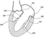
- Figure 1is a cutaway view of the left heart
- FIG. 2is a schematic structural view of a valve stent in an expanded state according to Embodiment 1 of the present invention
- FIG. 3is a partially enlarged schematic view showing the valve stent in an expanded state according to Embodiment 1 of the present invention
- Figure 4is a top plan view showing the annular structure of the valve stent in an expanded state according to the first embodiment of the present invention
- FIG. 5is another top view of the annular structure of the valve stent in an expanded state according to the first embodiment of the present invention
- Figure 6is still another plan view of the annular structure of the valve stent in the expanded state according to the first embodiment of the present invention.
- Figure 7is still another plan view of the annular structure of the valve stent in the expanded state according to the first embodiment of the present invention.
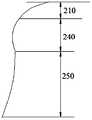
- Figure 8is a schematic view showing a contour of a valve stent in an expanded state according to a first embodiment of the present invention
- Figure 9is a schematic view showing another outline of the valve stent in an expanded state in the first embodiment of the present invention.
- Figure 10is a schematic view showing still another outline of the valve stent in an expanded state in the first embodiment of the present invention.
- Figure 11is a schematic view showing a portion of the valve stent released from the sheath tube in the first embodiment of the present invention
- Figure 12is a schematic view showing the valve stent of the first embodiment of the present invention completely released from the sheath and anchored in the natural mitral valve;
- Figure 13is a schematic view showing the structure of a valve stent in an expanded state according to a second embodiment of the present invention.
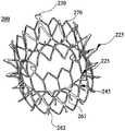
- Figure 14is a perspective view showing the structure of a valve stent according to a second embodiment of the present invention.
- Figure 15is a schematic view showing another valve stent in an expanded state according to a second embodiment of the present invention.
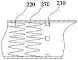
- Figure 16is a partial schematic view showing the valve holder being gripped in the sheath tube in the second embodiment of the present invention.
- FIG. 17is a schematic structural view of still another valve stent in an expanded state according to Embodiment 2 of the present invention.
- FIG. 18is a schematic structural view of still another valve stent in an expanded state according to Embodiment 2 of the present invention.
- Figure 19is a schematic view showing a portion of the valve stent released from the sheath tube in the second embodiment of the present invention.
- Figure 20is still another schematic view of a portion of the valve stent released from the sheath tube in the second embodiment of the present invention.
- Figure 21is a schematic view showing a portion of the valve stent of the second embodiment of the present invention completely released from the sheath and anchored in the natural mitral valve;
- Figure 22is a front elevational view of the valve prosthesis of the third embodiment of the present invention in an expanded state
- Figure 23is a plan view of the valve prosthesis of the third embodiment of the present invention in an expanded state.
- 101-mitral annulus101-mitral annulus; 102-mitral valve leaflet; 103-choscis; 104-papillary muscle;
- 210-inflow channel structure220-annular structure; 221-first end; 222-second end; 224-first pole; 225-first node; 230-hanger; 231-third end ;232-fourth end;
- 250-outflow channel structure251-seventh end; 252-eighth end; 254-third wave rod; 255-third node; 256-first section;
- FIG. 1is a cutaway view of the left heart.
- the native mitral valveis located on the left ventricular outflow tract structure from the left atrium to the left ventricle, as is the "check valve” placed on the left ventricular inflow tract.
- the natural mitral valveincludes a mitral annulus 101, a mitral valve leaflet 102, a chordae 103, and a papillary muscle 104.
- the papillary muscle 104is attached to the myocardial wall, and one end of the chordae 103 is connected to the papillary muscle 104, and the other end is connected to the mitral valve leaflet 102.
- Mitral valve prosthesestypically include a mitral valve and a mitral valve stent.
- the mitral valve prosthesisis released into the natural mitral valve, replacing the original natural mitral valve to achieve the "check valve" function.
- the mitral valve prosthesisis implanted, the mitral valve prosthesis is anchored by the interference fit of the mitral valve stent with the mitral annulus 101 and the mitral valve leaflet 102.
- most patients with mitral regurgitationhave a lower degree of mitral calcification, which does not provide sufficient anchoring force through an interference fit, resulting in instability of the mitral valve anchorage.
- the tricuspid valveacts as the atrioventricular valve of the right heart, and its structure is similar to that of the mitral valve. It also includes the leaflets, annulus, chordae, and papillary muscles.
- the principle of transcatheter mitral valve implantation and transcatheter tricuspid valve implantationis the same, and the principle of the mitral valve prosthesis can also be applied to the tricuspid valve prosthesis.
- the tricuspid prosthesisis also present because most patients with tricuspid regurgitation have a lower degree of tricuspid calcification, which does not provide sufficient anchoring force through an interference fit, resulting in a tricuspid prosthesis anchoring. Stable problem.
- the inventorshave proposed a valve stent and a valvular prosthesis to improve the instability of the existing mitral valve stent, mitral valve prosthesis, tricuspid valve stent, and tricuspid valve prosthesis instability.
- the natural valveincludes a natural mitral valve and a natural tricuspid valve.
- the valve stent and valvular prosthesis of the present inventionare further described in detail below with reference to the accompanying drawings and specific embodiments. It should be noted that the drawings are in a very simplified form and both use non-precise proportions, and are only for convenience and clarity to assist the purpose of the embodiments of the present invention.
- the valve stent of the following embodimentscan be applied to both the mitral valve stent and the tricuspid valve stent.
- the valve prosthesisis suitable for both the mitral valve prosthesis and the tricuspid valve prosthesis.
- the followingis an example of a mitral valve stent and a mitral valve prosthesis.
- outwardrefers to an extension line that extends in a radial direction starting from the central axis of the valve support, including both an extension line that is radially expanded perpendicular to the central axis, and a non-orthogonal approach to the central axis.
- Radially-expanded extension line; “inwardly”means an extension line extending in a radial direction with the central axis of the valve support as an end point, including an extension line that is radially expanded perpendicular to the central axis, and also includes a central axis An extension line that radiates in a non-orthogonal manner.
- proximal and distalare relative orientations, relative positions, directions of elements or actions relative to each other from the perspective of a physician using the medical device, although “proximal” and “distal” It is not limiting, but “proximal” generally refers to the end of the medical device that is near the physician during normal operation, while “distal” generally refers to the end that first enters the patient.
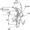
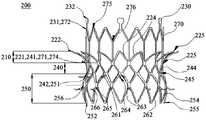
- FIG. 2is a schematic structural view of a valve stent in an expanded state according to Embodiment 1 of the present invention
- FIG. 3is a partially enlarged schematic view showing the valve stent in an expanded state according to Embodiment 1 of the present invention.
- the present embodimentprovides a valve stent 200 that is a self-expanding stent.
- the valve stent 200has a crimped state and an expanded state.
- the valve stent 200has a central axis (not shown), and the radial cross-section of the valve stent is perpendicular to the central axis of the valve stent 200.
- the central axisis a straight line.
- the central axismay also be curved.
- the valve support 200is in the form of a mesh. Specifically, the radial cross section of the valve stent 200 exhibits a circular distribution, and the size of the radial cross section of the valve stent 200 gradually changes along the central axis of the valve stent 200.
- the radial cross-section of the valve stent 200can also assume other shape distributions, such as along a D-ring or an elliptical ring, and the radial cross-section of the valve stent 200 is only a The central axis of the valve support 200 changes.
- the valve stent 200includes an inflow channel structure 210 in the form of a mesh, a transitional channel structure 240 in the form of a mesh, an outflow channel structure 250 in the form of a mesh, and a barbed structure.
- the inflow channel structure 210, the transition channel structure 240, and the outflow channel structure 250are sequentially connected in a web shape.
- the transition duct structure 240is located between the inflow channel structure 210 and the outflow channel structure 250.
- One end of the transition duct structure 240is fixedly connected to the inflow channel structure 210, and the other end is fixedly connected to the outflow channel structure 250.
- the barb structureis disposed on an outer circumferential surface of the outflow channel structure 250 and the transition channel structure 240.
- the inflow channel structure 210includes an annular structure 220.
- the valve support 200also includes a plurality of lugs 230.
- the annular structure 220has a mesh shape, and the annular structure 220 has a first end portion 221 and a second end portion 222, and the second end portion 222 is a free end.
- the diameter of the radial cross section of the first end portion 221 of the annular structure 220is smaller than the diameter of the radial cross section of the second end portion 222 of the annular structure 220. That is, the first end portion 221 of the annular structure 220 is a small end, and the second end portion 222 of the annular structure 220 is a large end.
- the annular structure 220smoothly transitions from the first end 221 to the second end 222.
- the outer contour of the annular structure 220fits over the left atrium port to facilitate positioning through the annular structure 220 during surgery. Specifically, the outer contour of the annular structure 220 fits over the annulus of the natural mitral valve of the left atrium chamber.
- FIG. 4is a top view of the annular structure of the valve stent in an expanded state according to the first embodiment of the present invention.
- the annular structure 220includes a set of first wave rod units. (not shown in the figure).
- the set of first wave rod unitsincludes a plurality of first wave rod units, and the adjacent two of the first wave rod units are sequentially fixedly connected.
- the first wave rod unitis composed of two first wave rods 224, and the shape of the first wave rod unit is, for example, a V shape.
- Each two adjacent first wave rods 224extend from the first end 221 of the annular structure 220 toward the second end 222 of the annular structure 220 and intersect.
- Two adjacent first wave bars 224 of two adjacent first wave bar unitsare fixedly coupled at a first end 221 of the annular structure 220.
- a connection point at which the two first wave bars 224 of the first wave bar unit are connected to each other at the second end portion 222is the first node 225.
- the annular structure 220may include a plurality of sets of first wave rod units. From the first end portion 221 of the annular structure 220 to the second end portion 222 of the annular structure 220, a plurality of sets of first wave rod units are sequentially connected.
- 7is still another top view of the annular structure of the valve stent in the expanded state according to the first embodiment of the present invention.
- the annular structuremay include three sets of first wave rod units, and for example, The annular structure may comprise two, four or five sets of first wave rod units. Adjacent sets of first wave rod units are interconnected by a first node of each set of first wave rod units to increase the strength of the annular structure and simplify the annular structure.
- the first wave rod unitmay be a triangle, a U shape, a diamond shape, a pentagon shape or the like composed of a plurality of first wave rods.
- Fig. 6is still another plan view of the annular structure of the valve stent in the expanded state according to the first embodiment of the present invention.
- the first wave rod unitis a pentagon or the like.
- the first wave rod unitis V-shaped.
- FIG. 5is another top view of the annular structure of the valve stent in the expanded state according to the first embodiment of the present invention.
- the first wave rod unitmay further include only one rod-shaped first wave rod 224. .
- the diameter of the second end 222 of the annular structure 220is greater than the largest diameter of the chamber opening.
- the annular structure 220preferably has a diameter of 30 mm to 70 mm to prevent the valve stent 200 from falling into the left ventricle when the heart is dilated.
- Figure 8is a schematic view showing a contour of the valve stent in an expanded state according to the first embodiment of the present invention.
- the angle between the annular structure 220 and the first direction F1is a first angle ⁇ 1.
- the first angle ⁇ 1is at least 60° and the maximum is 150°.
- the first direction F1is parallel to the central axis of the valve support 200 and from the first end 221 of the annular structure 220 to the second end 222.
- the annular structure 220can cover the left atrioventricular opening.
- the second end 222 of the annular structure 220can extend into the left atrium, covering the chamber opening and a portion of the left atrial wall structure.
- the first wave rod units of each grouphave the same size, that is, the annular structure 220 is a radially symmetric annular shape.
- the dimensions of the first wave rod units of each setare not uniform such that the radial cross-section of the annular structure 220 assumes other shapes, such as a D-ring or an elliptical ring.
- the mounting ears 230are in the shape of a rectangular plate. Of course, in other embodiments, the mounting ears may have other shapes, which are not limited in the present invention.
- the mounting ears 230are fixedly connected to the annular structure 220.
- the mounting ear 230has a third end portion 231 and a fourth end portion 232.
- the third end portion 231 of the mounting ear 230is fixedly connected to the annular structure 220, and the fourth end portion 232 is a free end.
- the lug 230is for attachment to a valve delivery device for facilitating delivery of the valve stent 200 into the native mitral valve.
- the third end 231 of the lug 230is fixedly connected to the second end 222 of the annular structure 220 . Further, the third end portion 231 of the mounting ear 230 is fixedly connected to the first node 225 located on the second end portion 222 of the annular structure 220.
- the lug 230extends from the third end portion 231 along a central axis of the valve stent 200 in a direction away from the second end portion 222 of the annular structure 220.
- the mounting earsare metal foils.
- the transition duct structure 240is fixedly coupled to the inflow channel structure 210.
- the transition duct structure 240includes a fifth end portion 241, a sixth end portion 242, and a first intermediate portion.
- the fifth end portion 241is fixedly coupled to the first end portion 221 of the annular structure 220.
- the six end portion 242is located at an end remote from the inflow channel structure 210, and the fifth end portion and the sixth end portion are located at both axial ends of the first intermediate portion. Referring to FIG.
- the diameters of the radial sections of the two end portions 241, 242 of the transition passage structure 240are larger than the diameter of the radial section of the first intermediate section, that is, the transition passage structure 240. It has a shape that is recessed inward.
- the transitional channel structure 240has an inwardly concave shape.
- the annulus and leaflets of the natural mitral valvecan be filled into the concave shape, so that the valve stent 200 can be anchored on the natural mitral valve, and on the other hand, the transition The shape of the channel structure 240 that is recessed inwardly facilitates matching the shape of the annulus of the native mitral valve to facilitate positioning of the valve stent 200 for the physician to release the valve stent 200 into the native mitral valve.
- the annulus and leaflets of the natural mitral valveare filled into the concave shape, so that the annulus and leaflets of the natural mitral valve can be better coated on the valve stent 200, thereby avoiding blood passing through the natural mitral valve.
- a gap with the valve support 200flows from the left atrium into the left ventricle.
- transition channel structure 240 and the annular structuretogether form a shape that is recessed inward.
- the diameter of the second end portion 222 of the annular structureis larger than the diameter of the first end portion 221, and the ring
- the radial structureextends the radial depth of the concave shape of the transitional passage structure 240 and increases the length of the concave shape along the central axis direction, so that more natural mitral valves are filled into the concave shape for anchoring the valve support More radial support is provided, and the inwardly recessed shape of the transitional structure 240 and the annular structure can be adapted to match the shape of the annulus of the native mitral valve, further facilitating the physician to deploy the valve support 200 Release into the natural mitral valve.
- the transition duct structure 240includes only one set of second pole unit.
- Each of the second wave rod unitsis composed of two second wave rods 244, and the shape of the second wave rod unit is V-shaped.
- Each two adjacent second wave rods 244extend and intersect in a direction near the fifth end portion 241 at a position near the sixth end portion 242.
- Two adjacent second wave rods 244 of two adjacent second wave rod unitsare fixedly coupled at a position near the sixth end portion 242.
- the second wave bars 244 interconnected in each set of second wave bar unitsform a second node 245.
- the first node 225 of the inflow channel structure 210is interconnected with the second node 245 of the transition channel structure 240 to increase the strength of the transition track structure 240 and to simplify the transition track structure 240.
- the transitional track structurecan include multiple sets of second wave bar units.
- a plurality of sets of second wave rod unitsare sequentially connected along the central axis of the valve support.
- Each of the second wave rod unitsincludes a plurality of second wave rod units, and the adjacent two of the second wave rod units are sequentially fixedly connected.
- the second wave rod unitmay be a triangle, a U shape, a diamond shape, a pentagon shape or the like formed of a plurality of second wave rods.
- the adjacent two sets of second wave rod unitsare preferably connected to each other by a second node of each set of second wave rod units.
- the diameter of the radial section of the transitional passage structure 240is larger than the diameter of the annulus of the natural mitral valve. Further, each of the transition passage structures 240 has a diameter of 25 mm to 55 mm.
- the shape of the inwardly recessed transition structure 240 along the central axis of the valve support 200is 2 mm to 20 mm.
- the outflow channel structure 250is fixedly coupled to the transition channel structure 240.
- the outflow channel structure 250has a seventh end portion 251, an eighth end portion 252, and a second intermediate portion, and the seventh end portion 251 of the outflow channel structure 250 is fixed to the sixth end portion 242 of the transition channel structure 240.
- the eighth end portion 252is located at an end away from the transitional passage structure 240, the eighth end portion 252 is a free end, and the seventh end portion 251 and the eighth end portion 252 are located in the second intermediate portion. Both ends of the axial direction of the segment.
- the outer peripheral surface of the outflow channel structure 250has a contour that protrudes toward the outside of the outflow channel structure 250, that is, the seventh end.
- the diameter of the radial section of the portion 251 and the diameter of the radial section of the eighth end portion 252are smaller than the diameter of the radial section of the second intermediate section.
- the section of the outflow channel structure 250 having the largest radial cross section diameteris the first section 256.
- the contours of the outer peripheral surfaces of the transition passage structure 240 and the outflow passage structure 250are S-shaped.
- the diameter of each radial section of the outflow channel structure 250may be other conditions.
- the diameter of each radial section of the outflow channel structurein the expanded state, is preferably larger than the seventh end.
- the shape of the outer expansionAlternatively, referring to FIG. 9, FIG. 9
- FIG. 10is a schematic view showing another outline of the valve stent in an expanded state according to the first embodiment of the present invention, wherein the diameters of the radial sections of the outflow channel structure 250 are equal, and the transition path is equal.
- Structure 240is cylindrical.
- FIG. 10is a schematic view showing still another outline of the valve stent in an expanded state according to the first embodiment of the present invention, wherein the diameter of each radial section of the outflow channel structure 250 is smaller than the seventh end. The diameter of the radial section of the portion 251.
- the diameter of the radial cross section of the outflow tract structure 250may also be varied in other ways, for example, the diameter of the radial section of the outflow tract structure 250 away from the seventh end 251 is greater than the seventh The diameter of the radial section of the end portion 251, the diameter of the radial section of the outflow channel structure 250 near the seventh end portion 251 is smaller than the diameter of the radial section of the seventh end portion 251.
- the outflow channel structure 250includes only a set of third wave rod units.
- Each of the third wave rod unitsis composed of four third wave rods 254, which are diamond shaped.
- the four sides of the third wave rod unitrespectively correspond to the four third wave rods 254.
- the third wave rod unithas four vertices.
- One vertex of the third wave rod unitis located on the eighth end portion 252, and the other vertex opposite the vertex on the eighth end portion 252 is located on the seventh end portion 251.
- the other two vertices of the third wave rod unitare fixedly connected to the vertices of the other two third wave rod units adjacent to the third wave rod unit, respectively.
- the other two vertices of the third wave rod unitare preferably located on the first section 256.
- the third wave rod unitis located at an apex on the eighth end portion 252, and the apex at the seventh end portion 251 is referred to as a third node 255.
- the second node 245 on the transitional track structure 240 and the third node 255 on the seventh end 251 of the outflow tract structure 250are interconnected to increase the strength of the outflow tract structure 250 and simplify the outflow tract structure 250. Structure.
- the outflow tract structure 250can include multiple sets of third wave rod units.
- a plurality of sets of third wave rod unitsare sequentially connected along the direction of the central axis of the valve stent 200. Adjacent sets of third wave rod units are preferably connected to each other by connecting points formed by connecting two or more third wave rods 254 on both ends of each set of third wave rod unit to improve The strength of the outflow channel structure 250 is reduced and the structure of the outflow channel structure 250 is simplified.
- Each of the third wave rod unitsincludes a plurality of third wave rod units, and the adjacent two of the third wave rod units are sequentially fixedly connected in a ring shape, such as a D-ring, an elliptical ring or a circular ring.
- the third wave rod unitmay be a triangle, a U shape, a V shape, a quadrangle or a pentagon formed by a plurality of third wave bars.
- Each radial section of the outflow tract structure 250has a diameter of 26 mm to 60 mm.
- the mounting ears 230may also be disposed on the outflow channel structure, for example, on the eighth end portion 252 of the outflow channel structure, and the third end portion 231 of the mounting ear 230 Attached to the eighth end portion 252, the fourth end portion 231 of the lug extends in a direction away from the outflow channel structure 250.
- the valve stent 200further includes a barbed structure including a plurality of first barbs 261 and a plurality of second barbs 262.
- the first barb 261has a first fixed end 263, and the second barb 262 has a second fixed end 265.
- the end of the first barb 261 away from the first fixed end 263is a first free end. 264.
- One end of the second barb 262 away from the second fixed end 265is a second free end 266.
- All of the first fixed ends 263 of the first barbs 261are disposed on the transitional track structure 240, and all of the first barbs 261 are external to the transitional path structure 240 from the first fixed end 263 Protruding.
- a plurality of second fixed ends 265 of the second barbs 262are disposed on the outflow channel structure 250, and all of the second barbs 262 are convex from the second fixed end 265 to the outer surface of the outflow channel structure 250.
- Out
- the plurality of the first barbs 261 and the plurality of the second barbs 262penetrate the leaflets and annulus tissue of the natural valve to anchor the valve stent 200 to the natural valve. on.
- the anchoring effect of the valve stent 200can be improved by anchoring the valve stent 200 to the natural mitral valve by the barbed structure together with the shape of the inner channel depression formed on the transitional channel structure 240 and the annular structure.
- the effect of the natural mitral valve 200 on the natural mitral valvecan be reduced by merely using the barbed structure or only through the transitional channel structure 240 and the inwardly recessed shaped anchoring valve stent 200 formed on the annular structure. Reduces the risk of fatigue damage to the natural mitral valve.
- all of the first fixed ends 263 of the first barbs 261are preferably located where the transition path structure 240 is connected to the outflow channel structure 250, that is, all of the first barbs 261.
- the first fixed end 263is disposed on the sixth end portion 242 of the transition channel structure 240 or on the seventh end portion 251 of the outflow channel structure 250.
- All of the second fixed ends 265 of the second barbs 262are disposed on the outflow channel structure 250.
- all of the first barbs 261extend in a direction close to the outflow channel structure 250.
- the first barb 261extends from a direction in which the transition duct structure 240 is connected to the outflow channel structure 250 toward a free end of the outflow channel structure 250 and is convex toward the outside of the valve stent 200.
- the first barb 261causes the shape of the inner recess formed by the transition duct structure 240 and the annular structure to be more recessed in the radial section, and the length spanned in the axial section is longer, so that More natural mitral valve annulus and leaflets are filled into the concave shape to stabilize the valve stent 200.
- first barb 261, the transitional channel structure 240 and the annular structuretogether form a shape recessed into the interior of the valve stent 200, which can facilitate positioning of the valve stent 200, so that the doctor can release the valve stent 200 to the natural two. In the cusp.
- valve stent 200is implanted with the natural structure of the heart as a guide to determine the release position of the valve stent 200.
- the shape of the transition channel structure 240 to the inner recesscan be matched with the annulus of the natural mitral valve to facilitate the valve stent.
- Positioning 200, and the first barb 261increases the shape of the recessed portion of the shape of the valve stent 200 formed by the transitional channel structure 240 and the annular structure, thereby allowing the valve stent 200 and the natural apex
- the matching region of the annulus of the valveis increased, thereby reducing the difficulty of positioning when the valve stent 200 is released, and increasing the length of the valve stent 200 that is adjustable along the central axis when the valve stent 200 is positioned, further reducing the physician's Operational difficulty.
- the plurality of the first barbs 261may be distributed on the transition channel structure 240 in other manners, for example, a portion of the first barbs 261 are distributed in the transition channel structure. Between the fifth end portion 241 and the sixth end portion 242 of the other portion, the first barb 261 of the other portion is distributed over the sixth end portion 242 of the transition path structure 240, and for example, all of the The first fixed ends 263 of a barb 261 are disposed between the fifth end 241 and the sixth end 242 of the transitional structure 240.
- all of the second fixed ends 265 of the second barbs 262are disposed on the first section 256.
- a plurality of the second barbs 262extend from the second fixed end 265 in a direction toward the eighth end 252 of the outflow channel structure 250. Since the second barb 262 is disposed on the first section 256 and the outflow channel structure 250 protrudes outward, and the second barb 262 is from the second fixed end 265 toward the outflow channel structure
- the direction of the eighth end portion 252 of the 250extends such that the shape of the outflow canal structure 250 and the transitional passage structure 240 that is recessed toward the interior of the valve stent 200 is more concave in the radial cross section.
- the length spanned in the axial sectionis longer, so that more of the natural mitral valve annulus and leaflets are filled into the concave shape, making the valve stent 200 more stable.
- the shape of the second barb 262, the outflow tract structure 250, the transitional channel structure 240 and the annular structure together to the interior of the valve stent 200can facilitate the positioning of the valve stent 200, facilitating the doctor to release the valve stent 200 to the nature. In the mitral valve.
- the shape of the interior of the valve stent 200which is formed by the second barb 262, the outflow tract structure 250, the transitional tract structure 240, and the annular structure, increases the area of the recess, thereby allowing the valve stent 200 to be attached to the natural mitral valve.
- the region of the annulus matchingis further increased, thereby further reducing the difficulty of positioning the valve stent 200 when released, and increasing the length of the valve stent 200 that is adjustable along the central axis when the valve stent 200 is positioned, further reducing the physician's Operational difficulty.
- the angle between the tangent of the first fixed end 263 and the second fixed end 265 of the first barb 261 and the second barb 262 and the second direction F2is a second angle. ⁇ 2, the second angle ⁇ 2 is at least 10° and the maximum is 150°.
- the second direction F2is in the axial cross-section of the valve stent 200, parallel to the central axis of the valve stent 200 and from the transitional channel structure 240 to the outflow channel structure 250.
- the extending direction of the first barb 261 and the second barb 262may be other manners, for example, a plurality of the first barbs 261 are adjacent to the outflow channel structure 250.
- the direction of the eighth end portion 252extends, and the plurality of the second barbs 262 extend in a direction approaching the seventh end portion 251 of the outflow channel structure 250.
- the first barb 261 and the second barb 262have the same shape and the same size.
- the first barb 261 and the second barb 262may be equal or unequal in size, and may be equal or unequal in shape, for example, distributed on the transition structure 240.
- the shape of one barb 261is the same, but the first barb 261 distributed between the two ends of the transition structure 240 is smaller than the first barb 261 distributed at the other end of the transition structure 240, the second inverted
- the size and shape of the thorn 262are the same as the first barb 261 distributed at the other end of the transitional path structure 240.
- the first barb 261 and the second barb 262have the same shape and the same size, for example, The shape of the barb 261 and the second barb 262 are different and the sizes are also different.
- first barb 261 and the second barb 262are preferably evenly distributed on the transition channel structure 240 and the outflow channel structure 250, so that the first barb 261 and the The second barb 262 evenly penetrates the leaflets and annulus tissue of the natural valve, so that the anchoring force applied by the natural valve to the valve stent 200 is uniform, the valve stent 200 is anchored stably, and the valve stent 200 acts on the nature.
- the force on the valveis also relatively uniform, mitigating damage to the native valve by the first barb 261 and the second barb 262.
- the manner in which the first barb 261 and the second barb 262 are distributed on the transition channel structure 240 and the outflow channel structure 250may be distributed in a non-uniform manner, for example, A plurality of the first barbs 261 are spaced apart at equal intervals on the seventh end portion 251 of the outflow channel structure 250.
- the second barbmay be disposed on the outflow channel structure in other manners, for example, the second barb may be disposed at a third node of the outflow channel structure, and The number and position of the second barbs are not limited.
- the transition channel structureis provided with a row of first barbs
- the outflow channel structureis provided with a row of second barbs, thereby preventing the barb structure from penetrating into the natural valve and following the valve prosthesis
- the axial agitationimproves the stability of the valve prosthesis anchorage.
- the length of the first barb 261 from the first fixed end 263 to the first free end 264is 0.5 to 8 mm
- the second barb 262is from the second fixed end 265 to the second free end 266.
- the lengthis 0.5 to 8 mm.
- first fixed end 263 of the first barb 261is fixedly connected to the second node 245, and the second fixed end 265 of the second barb 262 is opposite to the first section 256.
- the apex of the third wave rod unitis fixedly connected.
- the first barb 261can be coupled to other portions of the transition structure 240, and the second barbs 262 can also be coupled to the transition structure 240 and other portions of the outflow structure 250.
- first free end 264 of the first barb 261 and the second free end 266 of the second barb 262are both triangular tips or tapered shapes that are easy to penetrate into the natural valve.
- a smooth transitionoccurs between the first fixed end 263 of the first barb 261 and the first free end 264, and between the second fixed end 265 of the second barb 262 and the second free end 266 A smooth transition.
- the first barb 261 and the second barb 262are a combination of an arc or a plurality of arcs, and the arc starting points are respectively located at the first fixed end 263 of the first barb 261.
- the first barb 261 and the second barb 262are a combination of a circular arc and a straight line, and the arc starting point is respectively located at the first fixed end 263 and the second of the first barb 261.
- the second fixed end 265 of the barb 262, the first free end 264 of the first barb 261 and the second free end 266 of the second barb 262are both straight lines, the arc being tangent to the line.
- the barb structuremay include only the first barb or only the second barb.
- the sum of the lengths of the outflow tract structure 250 and the transitional tract structure 240 along the central axis directionis preferably 10 mm to 30 mm to minimize the effect of the valve stent 200 on the underlying mitral valve structure, which can reduce left ventricular remodeling and The risk of obstruction of the left ventricular outflow tract.
- the length of the valve stent 200 along the central axis directionis 10 to 60 mm.
- the valve stent 200can be made of Nitinol or other biocompatible material having memory properties.
- the valve stent 200can be released into the heart via the left atrium approach or released into the heart via the apical approach.
- the valve stent 200is released into the heart via the left atrial approach and released into the heart via the apical approach in that the valve stent 200 is released in a different order.
- the outflow tract structure 250is first released from the sheath
- the inflow tract structure 210is first released from the sheath.
- the followingis an example of the release of the valve stent 200 into the heart via the left atrium approach, illustrating the release of the valve stent 200 into the native mitral valve through the delivery system.
- valve stent 200is crimped into the sheath of the delivery system at the proximal end of the sheath, at which time the valve stent 200 is independent of the native mitral valve.
- valve stent 200is pushed through the pusher of the delivery system to the distal end of the sheath, and the valve stent 200 is released at the distal end of the sheath.
- valve stent 200When the valve stent 200 is released at the distal end of the sheath, the outflow tract structure 250 and the transitional channel structure 240 of the valve stent 200 are sequentially released from the sheath. A portion of the valve stent 200 released from the sheath automatically expands and assumes a conical configuration.
- FIG. 11is a schematic view showing a portion of the valve stent released from the sheath tube in the first embodiment of the present invention.
- the barb structurebegins to penetrate the leaflets and annulus of the natural mitral valve.
- the valve stent 200can still be recovered as a whole back into the sheath.
- valve stent 200continues to be released until the inflow channel structure 210 of the valve stent 200 is completely released from the sheath.
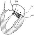
- FIG. 12is a schematic view of the valve stent 200 in the first embodiment of the present invention fully released from the sheath and anchored in the natural mitral valve.
- the valve stent 200expands, at which time the barbed structure is anchored to the leaflets and annulus of the native mitral valve under compression of the valve stent 200
- the annulus and leaflets of the natural mitral valveare filled into the shape of the inwardly recessed transitional structure 240 and are wrapped over the outer peripheral surface of the transitional passage structure 240.
- the annular structure 220 of the inflow channel structure 210can cover the annulus of the natural mitral valve.
- FIG. 13is a schematic structural view of a valve stent in an expanded state according to a second embodiment of the present invention
- FIG. 14is a perspective structural view of a valve stent according to a second embodiment of the present invention.
- the valve stent in the embodimentis different from the valve stent in the first embodiment in that the valve stent 200 in the embodiment further includes a web-shaped extension structure 270 , and the mounting ear 230 is not directly It is connected to the annular structure 220, but is connected to the annular structure 220 through the extension structure 270.
- the extension structureis fixedly connected to the annular structure.
- the extension structure 270has a ninth end portion 271 and a tenth end portion 272, the ninth end portion 271 being fixedly coupled to the annular structure 220, the tenth end portion 272 being away from the annular structure 220 and The transition track structure 240.
- the mounting ears 230are fixedly coupled to the extension structure 270.
- the length of the extension structure 270 along the central axis directionis greater than the length of the annular structure 220 along the central axis direction, and thus the annular structure 220 and the transition path structure
- the extension structure 270 and the lug 230are not yet released from the sheath, and thus the annular structure 220, the transitional structure 240, and the outflow tract structure 250 can be further avoided.
- the radial dimension caused by the expansionbecomes larger, and the dimension in the central axis direction becomes smaller, causing the problem that the valve stent 200 is axially swayed.
- valve stent 200is anchored to the natural mitral valve when the extension structure 270 and the lug 230 are released. Therefore, when the extension structure 270 and the lug 230 are released, the axial impact of the valve stent 200 is reduced, and the release stability is further improved.
- FIG. 15is a schematic view of another valve stent in an expanded state according to Embodiment 2 of the present invention.
- the valve stentreleases the outflow channel structure first, the inflow channel structure is released, and the crimping length of the annular structure is greater than
- the lugsare attached to the distal end of the annular structure.
- the stiffness of the valve stent 200 after crimpingcan be increased, and the stability of the valve stent 200 release can also be improved.
- the valve supportsuccessively releases the outflow channel structure and the transition channel structure, the inflow channel structure and the extension structure are released, and as the extension structure is gradually released, the diameter of the extension structure is gradually increased, the extension structure and the transition channel structure and outflow.
- the morphological morphology of the tractis further close to its expanded shape, thereby reducing the morphological change of the extension structure, the transition tract structure and the outflow tract structure when the valve stent is completely released, thereby improving the release stability.
- the extension structure 270 and the annular structure 220are axially staggered, that is, in the crimped state, the extension structure 270 is The annular structure 220 is only in contact at the junction of the two, with no overlap in the radial direction.
- 16is a partial schematic view of a valve stent in a sheath according to a second embodiment of the present invention. Referring to FIG. 16, after the valve stent 200 is crimped into the sheath, the extension structure 270 is offset from the annular structure 220. The distribution, thereby avoiding the extension structure 270, results in an increase in the diameter of the valve stent 200 after crimping.
- the maximum diameter of the extension structure 270 in the radial sectionis smaller than the maximum diameter of the annular structure in the radial section, and the extension structure 270 is prevented from affecting the annular structure 220 to cover the natural
- the extension structure 270affects the positioning of the valve stent 200 when the annulus of the cusp is removed and the valve stent 200 is prevented from being released.
- the ninth end portion 271 of the extension structure 270is preferably fixedly connected to the first end portion 221 of the annular structure 220 .
- the extension structure 270includes a set of fourth wave rod units.
- the fourth wave rod unitincludes a fourth wave rod in a Y shape.
- Each of the fourth wave rodshas a first connection end 274 and two second connection ends 275.
- the first connecting end 274is preferably fixedly coupled to the first end 221 of the annular structure 220.
- Two adjacent second connection ends 275 of two adjacent fourth wave rod unitsare fixedly connected.
- the two second connection ends 275are preferably arranged symmetrically.
- the three-pronged intersection of the Y-type fourth wave bar included in each of the fourth wave bar units of each of the fourth wave bar unitsforms a fourth node 276.
- the extension structure 270can include multiple sets of fourth wave rod units. From the ninth end portion 271 of the extension structure 270 to the tenth end portion 272 of the extension structure 270, a plurality of sets of fourth wave rod units are sequentially connected. Each of the fourth wave rod units includes a plurality of fourth wave rod units, and the adjacent two of the fourth wave rod units are sequentially fixedly connected. Adjacent sets of fourth wave rod units are preferably interconnected by a fourth node 276 of each set of fourth wave rod units to increase the strength of the annular structure 220 and simplify the annular structure 220, and not each of said fourth The first connection end 274 of the pole is coupled to a fourth node 276.
- the extension structure 270can include three sets of fourth wave rod units, and for example, the extension structure 270 can include two, four, or five sets of fourth wave rod units.
- the fourth wave rod unitmay be a triangle, a U shape, a diamond shape, a pentagon shape or the like composed of a plurality of fourth wave rods.
- FIG. 17is a schematic structural view of still another valve stent in an expanded state according to Embodiment 2 of the present invention, and the fourth wave rod unit may further include only one rod-shaped fourth wave rod.
- the extension structure 270is integrally formed. In other embodiments, the extension structure 270 can be joined by other processing methods of the fourth wave rod unit.
- the fourth wave rod unitcan be fixedly connected, for example, by welding.
- the extension structure 270is integrally formed with the annular structure 220.
- the extension structure 270 and the annular structure 220are connected by rigid connection such as welding, riveting, or the like, or by a flexible connection such as braiding.
- the length of the extension structure 270 along the central axis of the valve stent 200can be from 1 to 25 mm.
- the third end portion 231 of the mounting ear 230is preferably fixedly connected to the point where the extending structure 270 is located on the tenth end portion 272, and the fourth end portion 232 of the mounting ear is free. end.
- the lug 230extends along a central axial direction of the valve stent 200 near a second end 222 of the annular structure 220.
- the outer peripheral faces of the plurality of the lugs 230are preferably cylindrical.
- FIG. 18is a schematic structural view of still another valve stent in an expanded state according to Embodiment 2 of the present invention.
- the extension structure 270includes a set of fourth wave rod units.
- the fourth wave rod unitincludes a plurality of Y-shaped fourth wave rods and a plurality of V-shaped fourth wave rods.
- Each of the Y-shaped fourth wave rodshas a first connection end 274 and two second connection ends 275, and each of the V-shaped fourth wave rods has only a second connection end 275.
- a plurality of Y-shaped fourth wave rods and a plurality of V-shaped fourth wave rodsare connected by a second connecting end 275, the first connecting end 274 and the first end portion 221 of the annular structure 220 Fixed connection.
- the third end 231 of the mounting ear 230is fixedly connected to the fourth node 276.
- the number of the fourth wave rods of the Y type in FIG. 18is smaller than the number of the fourth wave rods of the Y type shown in FIG. 13, and the extending structure 270 and the ring shape described in FIG. The flexibility of the connection between the structures is better.
- valve stent 200is released into the heart through the left atrium approach, and the process of releasing the valve stent 200 into the natural mitral valve through the delivery system is illustrated.
- valve stent 200is crimped from the proximal end of the sheath into the sheath of the delivery system, at which time the valve stent 200 is independent of the native mitral valve.
- valve stent 200is pushed through the pusher of the delivery system to the distal end of the sheath, and the valve stent 200 is released at the distal end of the sheath.
- valve stent 200When the valve stent 200 is released at the distal end of the sheath, the outflow tract structure 250 and the transitional channel structure 240 of the valve stent 200 are sequentially released from the sheath. A portion of the valve stent 200 released from the sheath automatically expands, exhibiting a conical configuration as compared to the sheath.
- valve stent 200Continuing to release the valve stent 200, the barbs begin to penetrate into the leaflets and annulus of the native mitral valve, and thus, the valve stent 200 can still be recovered as a whole back into the sheath.
- the annular structure 220 of the inflow channel structure 210is released from the sheath tube, with a portion of the extension structure 270 being located in the sheath tube and the lug 230 not being released from the sheath tube.
- valve stent 200continues to be released until the extension structure 270 and the lug 230 are completely released from the sheath.
- FIG. 19is a schematic view showing a part of the valve stent released from the sheath tube in the second embodiment of the present invention
- Figure 20is a schematic view showing a part of the valve stent released from the sheath tube in the second embodiment of the present invention
- 21is a schematic view of a portion of the valve stent of the second embodiment of the present invention fully released from the sheath and anchored in the natural mitral valve.
- the outflow tract structure 250first emerges from the sheath.
- the valve stent 200is released into the native mitral valve, the valve stent 200 is inflated, at which time the barb structure is anchored to the leaflets and annulus of the native mitral valve, in the valve Under the compression of the stent 200, the annulus and leaflets in the natural mitral valve are filled into the shape of the inwardly recessed transitional structure 240 and are wrapped over the outer peripheral surface of the transitional channel structure 240, a portion of the extension structure 270 and All of the mounting ears 230 are also located in the sheath.
- the barb structureis anchored to the leaflets and annulus of the native mitral valve, the annular structure
- the 220covers the annulus of the natural mitral valve, that is, covers the left ventricular inflow channel structure, and the extension structure 270 and the mounting ear 230 are located in the left atrium.
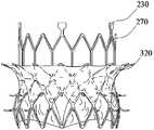
- FIG. 22is a front view of the valve prosthesis in the third embodiment of the present invention in an expanded state
- FIG. 23is a valve prosthesis in the third embodiment of the present invention.
- the top view of the body in the expanded statefor example, includes the valve stent 200 and the valve assembly of the above embodiments.
- the valve assemblyis attached to the valve support 200.
- the valve assemblyincludes a prosthetic leaflet 310 (see Figure 23) and a suture skirt 320 (see Figure 22).
- the prosthetic leaflet 310 and the suture skirt 320are attached to the valve support 200 by stitching.
- the prosthetic leaflets 310are sewn to the interior of the transitional channel structure 240 and the outflow tract structure 250 for use in directing blood along the inflow channel structure 210 to the outflow tract structure 250.
- the interior of the valve stent 200flows through to replace the valve of the natural mitral valve to achieve a one-way valve function that prevents blood from entering the left atrium from the left ventricle.
- the leafletsare three pieces. In other embodiments, the number of leaflets may also be two or more.
- the stitching skirt 320covers the loop structure 220, the transition duct structure 240, and the outflow channel structure 250, and the stitching skirt 320 does not cover the extension structure 270 and the lug 230.
- the stitching skirt 320preferably covers the outer peripheral faces of the annular structure 220, the transition channel structure 240, and the outflow channel structure 250.
- the suture skirt 320is used to prevent blood from flowing from the left atrium into the left ventricle from the outer peripheral surface of the annular structure 220, the transitional structure 240, and the outflow tract structure 250, that is, the suture skirt 320 allows blood to pass only from the left atrium.
- the prosthetic valve leaflet 310flows into the left ventricle, so that the flow path of the blood is single, and the formation of a thrombus between the valve prosthesis and the annulus of the natural mitral valve and the leaflet can be avoided.
- the prosthetic leaflet 310 and the suture skirt 320can be biologically treated animal pericardium or other biocompatible polymeric material.
- the annular structure 220covers the annulus of the natural mitral valve, and the transitional tract structure 240 and the outflow tract structure 250 are located on the annulus and leaflets of the natural mitral valve, and the barbed structure penetrates In the annulus and leaflets of the natural mitral valve, under the compression of the valvular prosthesis, the annulus and leaflets of the natural mitral valve are filled into the concave shape formed by the transitional channel structure 240 and the barb structure, so that the natural apex An annulus and a leaflet of the flap overlie the outer peripheral surface of the transitional channel structure 240 and the outflow tract structure 250.
- the prosthetic leaflets 310When the heart is dilated, the prosthetic leaflets 310 naturally open due to blood shock, allowing blood to enter the left ventricle from the left atrium. Due to the action of the suture skirt 320, blood is prevented from entering the left ventricle from the left atrium through the annulus of the native mitral valve and the gap between the leaflets and the peripheral surface of the valve prosthesis.
- the heartcontracts, the pressure in the left ventricle rises, the prosthetic leaflet 310 closes, under the action of the suture skirt 320, and the natural mitral valve is filled under the influence of the invaginal shape of the transitional channel structure 240, the blood is contracted by the heart. Unable to enter the left atrium through the valve prosthesis.
- the valve prosthesisreplaces the natural mitral valve to achieve the function of the one-way valve.
- valve prosthesis having the valve stent of the second embodimentis released into the heart through the left atrium approach, and the process of releasing the valve prosthesis into the natural mitral valve through the delivery system is illustrated.
- valve prosthesisis crimped from the proximal end of the sheath into the sheath of the delivery system, at which time the valve prosthesis is independent of the native mitral valve.
- valve prosthesisis pushed through the pusher of the delivery system to the distal end of the sheath to release the valve prosthesis at the distal end of the sheath.
- the valvular prosthesisWhen the valvular prosthesis is released at the distal end of the sheath, the outflow tract structure and the transitional tract structure of the valvular prosthesis are sequentially released from the sheath.
- the partial valve prosthesis released from the sheathautomatically expands, presenting a conical structure compared to the sheath.
- the valvular prosthesiscontinues to be released and the barbs begin to penetrate the leaflets and annulus of the native mitral valve, and the valve prosthesis can still be recovered back into the sheath.
- valve prosthesiscontinues to be released, and the annular structure of the inflow tract structure is released from the sheath. At this time, part of the extension structure is located in the sheath tube, and the hanging ear is not released from the sheath tube.
Landscapes
- Health & Medical Sciences (AREA)
- Engineering & Computer Science (AREA)
- Biomedical Technology (AREA)
- Cardiology (AREA)
- Oral & Maxillofacial Surgery (AREA)
- Transplantation (AREA)
- Heart & Thoracic Surgery (AREA)
- Vascular Medicine (AREA)
- Life Sciences & Earth Sciences (AREA)
- Animal Behavior & Ethology (AREA)
- General Health & Medical Sciences (AREA)
- Public Health (AREA)
- Veterinary Medicine (AREA)
- Prostheses (AREA)
Abstract
Description
Translated fromChinese本发明涉及医疗器械技术领域,特别涉及一种瓣膜支架和瓣膜假体。The present invention relates to the field of medical device technology, and in particular to a valve stent and a valve prosthesis.
心脏含有四个心腔,左心房与左心室位于心脏左侧,右心房与右心室位于心脏右侧。心房与心室间形成心室流入道结构,左心室与主动脉形成左室流出道结构,右心室与肺动脉形成右室流出道结构。在心室流入道结构、左室流出道结构和右室流出道结构处存在瓣膜。瓣膜具有“单向阀”功能,以保证心腔内血液的正常流动。当瓣膜出现问题时,心脏血液动力学改变,心脏功能异常,称为瓣膜性心脏病。The heart contains four heart chambers, the left atrium and the left ventricle are on the left side of the heart, and the right atrium and right ventricle are on the right side of the heart. The ventricular inflow tract structure is formed between the atrium and the ventricle, the left ventricle and the aorta form a left ventricular outflow tract structure, and the right ventricle and the pulmonary artery form a right ventricular outflow tract structure. A valve is present at the ventricular inflow tract structure, the left ventricular outflow tract structure, and the right ventricular outflow tract structure. The valve has a "check valve" function to ensure proper flow of blood within the heart chamber. When there is a problem with the valve, the heart's hemodynamics change and the heart function is abnormal, called valvular heart disease.
随着社会经济的发展和人口的老龄化,瓣膜性心脏病的发病率明显增加,研究表明75岁以上的老年人群瓣膜性心脏病发病率高达13.3%。采用传统外科手术治疗仍是重度瓣膜病变患者的首选治疗手段,但对于高龄、合并多器官疾病、有开胸手术史以及心功能较差的患者,传统外科手术的风险大、死亡率高,部分患者甚至没有手术的机会。其中,由于高龄、并发症和左心室功能损害,高达50%的有症状的重度二尖瓣反流患者并不适合进行传统的二尖瓣修复或置换术。于是,可有效降低手术风险和死亡率的介入手术逐渐获得了肯定。然而传统介入手术依赖体外循环(Cardiopulmonary Bypass,CPB),手术持续时间较长。相比之下,经导管瓣膜置入术和经导管瓣膜修复术具有无需开胸、创伤小、患者恢复快等优点,因此在介入手术中得到了广泛应用。With the development of social economy and the aging of the population, the incidence of valvular heart disease has increased significantly. Studies have shown that the incidence of valvular heart disease in the elderly over 75 years old is as high as 13.3%. Traditional surgical treatment is still the treatment of choice for patients with severe valvular disease, but for advanced age, multiple organ disease, history of thoracotomy, and poor cardiac function, traditional surgery has a high risk and high mortality. The patient did not even have a chance of surgery. Among them, up to 50% of patients with symptomatic severe mitral regurgitation are not suitable for conventional mitral valve repair or replacement due to advanced age, complications, and left ventricular dysfunction. As a result, interventional procedures that can effectively reduce surgical risk and mortality have gradually gained recognition. However, traditional interventional surgery relies on Cardiopulmonary Bypass (CPB), which lasts longer. In contrast, transcatheter valve placement and transcatheter valve repair have the advantages of no need for thoracotomy, small trauma, and rapid recovery of the patient, and thus have been widely used in interventional procedures.
近年来开发了经导管主动脉瓣植入术,对主动脉瓣膜进行介入替换并取得较好的治疗效果。西方国家中经导管主动脉瓣植入术的适用人群,由高危人群向中低危人群逐渐过渡;在中国,经导管主动脉瓣植入术逐步推广,并具有多家自主创新研究品牌。In recent years, transcatheter aortic valve implantation has been developed to replace the aortic valve and achieve better therapeutic results. In Western countries, the application of transcatheter aortic valve implantation gradually transitions from high-risk groups to low-risk groups. In China, transcatheter aortic valve implantation is gradually promoted, and there are many independent innovation research brands.
与经导管主动脉瓣植入术相比,经导管二尖瓣植入术和经导管三尖瓣植入术则具有更多的挑战。二尖瓣又称僧帽瓣,其位于左心室流入道结构处,主要结构为二尖瓣复合体,包括二尖瓣瓣环、瓣叶、腱索、左乳头肌、右乳头肌和 心肌。二尖瓣的瓣叶为附于左室口周缘的前后两片瓣膜。二尖瓣的瓣叶通过腱索与前、后乳头肌连接。乳头肌附着于心室壁上。三尖瓣作为右心脏的房室瓣,其结构与二尖瓣类似,也包含瓣叶、瓣环、腱索、乳头肌及心肌。Transcatheter mitral valve implantation and transcatheter tricuspid valve implantation have more challenges than transcatheter aortic valve implantation. The mitral valve, also known as the iliac crest flap, is located at the left ventricular inflow tract structure. The main structure is the mitral valve complex, including the mitral annulus, leaflets, chordae, left papillary muscle, right papillary muscle, and myocardium. The leaflets of the mitral valve are the anterior and posterior valves attached to the periphery of the left ventricular septum. The leaflets of the mitral valve are connected to the anterior and posterior papillary muscles by chordae. The papillary muscles are attached to the ventricular wall. The tricuspid valve acts as the atrioventricular valve of the right heart. Its structure is similar to that of the mitral valve. It also includes the leaflets, annulus, chordae, papillary muscles and myocardium.
由于二尖瓣和三尖瓣结构的复杂性,二尖瓣假体和三尖瓣假体植入到心脏内后,锚固是否稳定成为经导管二尖瓣植入术和经导管三尖瓣植入术急需解决的问题。Due to the complexity of the mitral and tricuspid structures, whether the anchoring is stable after transcatheter mitral valve implantation and transcatheter tricuspid valve implantation after implantation of the mitral and tricuspid prosthesis into the heart The problem that needs to be solved urgently.
发明内容Summary of the invention
本发明的目的在于提供一种瓣膜支架和瓣膜假体,以解决现有的瓣膜支架和瓣膜假体锚固不稳定的技术问题。It is an object of the present invention to provide a valve stent and a valve prosthesis to address the technical problems of existing valve stent and valve prosthesis anchor instability.
为解决上述技术问题,本发明提供一种瓣膜支架,所述瓣膜支架为自膨胀式支架,所述瓣膜支架呈网管状,所述瓣膜支架具有压握状态和膨胀状态;所述瓣膜支架包括流入道结构、过渡道结构、流出道结构和倒刺结构,所述流入道结构、所述过渡道结构和所述流出道结构依次连接,所述倒刺结构设置于所述过渡道结构和/或所述流出道结构上;所述流入道结构包括环状结构,所述环状结构具有第一端部和第二端部,所述第二端部为自由端,在膨胀状态下,所述环状结构的第一端部的径向截面的直径小于所述环状结构的第二端部的径向截面的直径;所述过渡道结构具有第五端部、第六端部和第一中间段,所述第五端部和所述第六端部位于所述第一中间段的轴向的两端,所述第五端部与所述环状结构的第一端部固定连接,所述第六端部远离所述流入道结构,在膨胀状态下,所述第五端部和第六端部的径向截面的直径大于所述过渡道结构的第一中间段的径向截面的直径;所述流出道结构具有第七端部和第八端部,所述流出道结构的第七端部与所述过渡道结构的第六端部固定连接,所述第八端部远离所述过渡道结构与流入道结构,所述第八端部为自由端;所述倒刺结构向所述过渡道结构和/或所述流出道结构的外部凸出。In order to solve the above technical problem, the present invention provides a valve stent, the valve stent is a self-expanding stent, the valve stent is in a mesh tube shape, the valve stent has a pressure grip state and an expanded state; and the valve stent includes an inflow a channel structure, a transition channel structure, an outflow channel structure, and a barbed structure, wherein the inflow channel structure, the transition channel structure, and the outflow channel structure are sequentially connected, and the barb structure is disposed in the transition channel structure and/or The outflow channel structure; the inflow channel structure includes an annular structure having a first end and a second end, the second end being a free end, in an expanded state, the a diameter of a radial section of the first end of the annular structure is smaller than a diameter of a radial section of the second end of the annular structure; the transitional passage structure having a fifth end, a sixth end, and the first In the middle section, the fifth end portion and the sixth end portion are located at two axial ends of the first intermediate portion, and the fifth end portion is fixedly connected to the first end portion of the annular structure, The sixth end portion is away from the inflow channel junction a diameter of a radial section of the fifth end portion and the sixth end portion being larger than a diameter of a radial section of the first intermediate portion of the transition passage structure in an expanded state; the outflow passage structure having a seventh An end portion and an eighth end portion, the seventh end portion of the outflow channel structure being fixedly coupled to the sixth end portion of the transition passage structure, the eighth end portion being away from the transition passage structure and the inflow channel structure, The eighth end portion is a free end; the barb structure protrudes toward the outside of the transition path structure and/or the outflow channel structure.
可选的,所述倒刺结构包括多个第一倒刺和多个第二倒刺,每个所述第一倒刺和所述第二倒刺均具有一固定端,每个所述第一倒刺和所述第二倒刺远离所述固定端的一端为自由端,所有的所述第一倒刺的固定端均设置于所述过渡 道结构上,所有的所述第一倒刺自固定端向所述过渡道结构的外部凸出,多个所述第二倒刺的固定端位于所述流出道结构上,所有的所述第二倒刺自固定端向所述流出道结构的外部凸出。Optionally, the barb structure comprises a plurality of first barbs and a plurality of second barbs, each of the first barbs and the second barbs having a fixed end, each of the One barb and one end of the second barb away from the fixed end are free ends, and all the fixed ends of the first barb are disposed on the transition channel structure, all of the first barbs are a fixed end protruding toward an outer portion of the transition channel structure, a plurality of fixed ends of the second barb being located on the outflow channel structure, all of the second barbs being fixed from the fixed end to the outflow channel structure Externally convex.
可选的,所有的所述第一倒刺的固定端位于所述过渡道结构的第六端部上,所有的所述第二倒刺的固定端位于所述流出道结构上。Optionally, all the fixed ends of the first barb are located on the sixth end of the transitional track structure, and all the fixed ends of the second barbs are located on the outflow channel structure.
可选的,流出道结构具有位于所述第七端部和第八端部之间的第二中间段,在膨胀状态下,所述第七端部的径向截面的直径和所述第八端部的径向截面的直径,小于所述第二中间段的径向截面的直径,所述流出道结构径向截面直径最大的截面为第一截面,所有的所述第二倒刺位于所述流出道结构的所述第一截面。Optionally, the outflow channel structure has a second intermediate section between the seventh end and the eighth end, the diameter of the radial section of the seventh end and the eighth in the expanded state The diameter of the radial section of the end portion is smaller than the diameter of the radial section of the second intermediate section, and the section having the largest radial section diameter of the outflow channel structure is the first section, and all of the second barbs are located at the Said first section of the outflow tract structure.
可选的,所述瓣膜支架包括延伸结构,所述延伸结构具有第九端部和第十端部,所述第九端部与所述环状结构固定连接,所述第十端部远离所述环状结构和所述过渡道结构。Optionally, the valve support comprises an extension structure having a ninth end portion and a tenth end portion, the ninth end portion being fixedly connected with the annular structure, and the tenth end portion being away from the The annular structure and the transitional channel structure.
可选的,所述瓣膜支架压握后,所述延伸结构的轴向长度大于所述环状结构的轴向长度。Optionally, after the valve holder is crimped, the axial length of the extension structure is greater than the axial length of the annular structure.
可选的,所述瓣膜支架压握后,所述延伸结构的轴向长度小于所述环状结构的轴向长度。Optionally, after the valve holder is crimped, the axial length of the extension structure is smaller than the axial length of the annular structure.
可选的,所述瓣膜支架压握后,所述流入道和所述延伸结构在径向方向上无重叠。Optionally, after the valve holder is crimped, the inflow channel and the extension structure do not overlap in a radial direction.
可选的,所述延伸结构的径向截面的最大直径小于所述环形结构的径向截面的最大直径。Optionally, the maximum diameter of the radial section of the extension structure is smaller than the largest diameter of the radial section of the annular structure.
可选的,所述延伸结构的第九端部与所述环状结构的第一端部固定连接。Optionally, the ninth end of the extension structure is fixedly connected to the first end of the annular structure.
可选的,所述瓣膜支架还包括多个挂耳,所述延伸结构的第十端部与所述挂耳固定连接。Optionally, the valve support further includes a plurality of lugs, and the tenth end of the extension structure is fixedly connected to the lug.
可选的,所述延伸结构包括至少一组第四波杆单元,所述一组第四波杆单元包括多个呈Y型的第四波杆。Optionally, the extension structure comprises at least one set of fourth wave rod units, and the group of fourth wave rod units comprises a plurality of fourth wave rods in a Y shape.
可选的,所述瓣膜支架包括延伸结构,所述延伸结构具有第九端部和第十端部,所述第九端部与所述过渡道结构固定连接,所述第十端部远离所述过渡 道结构。Optionally, the valve support comprises an extension structure having a ninth end portion and a tenth end portion, the ninth end portion being fixedly connected with the transition passage structure, and the tenth end portion being away from the The transitional path structure.
可选的,在所述膨胀状态下,所述流出道结构和过渡道结构的轴向长度之和为10mm至35mm。Optionally, in the expanded state, the sum of the axial lengths of the outflow channel structure and the transition channel structure is 10 mm to 35 mm.
可选的,所述瓣膜支架的环状结构的径向截面形状呈圆环、椭圆环或者D型环。Optionally, the annular structure of the valve stent has a radial cross-sectional shape of a ring, an elliptical ring or a D-ring.
本发明还提供一种瓣膜假体,包括上述的瓣膜支架、假体瓣叶和缝合裙边,所述假体瓣叶和缝合裙边附着于所述瓣膜支架上,所述假体瓣叶位于所述过渡道结构和所述流出道结构的内部,所述缝合裙边覆盖在环状结构、过渡道结构和流出道结构上,所述缝合裙边与假体瓣叶建立单一的血液通道,用于使血液沿着流入道结构到流出道结构的方向从瓣膜支架的内部流过。The present invention also provides a valve prosthesis comprising the above-described valve stent, prosthetic leaflet and suture skirt, the prosthetic leaflet and suture skirt being attached to the valve support, the prosthetic leaflet being located The transition channel structure and the interior of the outflow channel structure, the suture skirt is covered on the annular structure, the transition channel structure and the outflow channel structure, the suture skirt and the prosthetic valve leaflet establish a single blood channel, It is used to flow blood from the inside of the valve stent in the direction of the inflow channel structure to the outflow channel structure.
可选的,所述延伸结构上无缝合裙边附着。Optionally, the extension structure is seamlessly attached to the skirt.
本发明提供的一种瓣膜支架和瓣膜假体,具有以下有益效果:The invention provides a valve stent and a valve prosthesis, which have the following beneficial effects:
由于在膨胀状态下,过渡道结构的第五端部和第六端部的径向截面的直径大于所述过渡道结构的第一中间段的径向截面的直径,即所述过渡道结构呈向内凹陷的形状,一方面可使瓣膜支架植入自然二尖瓣中后,自然二尖瓣的瓣环和瓣叶填充到该凹陷形状中,便于瓣膜支架锚固在自然二尖瓣上;另一方面过渡道结构呈向内凹陷的形状可便于与自然二尖瓣的瓣环的形状相匹配,从而便于瓣膜支架定位,便于医生将瓣膜支架释放到自然二尖瓣中;此外,自然二尖瓣的瓣环和瓣叶填充到该凹陷形状中,可使自然二尖瓣的瓣环和瓣叶更好的包覆在对瓣膜支架上,从而避免血液经自然二尖瓣与瓣膜支架之间的间隙从左心房流入左心室。Since the diameter of the radial cross section of the fifth end portion and the sixth end portion of the transition passage structure is larger than the diameter of the radial cross section of the first intermediate portion of the transition passage structure in the expanded state, that is, the transition passage structure is The shape of the inward depression, on the one hand, after the valve stent is implanted into the natural mitral valve, the annulus and leaflets of the natural mitral valve are filled into the concave shape, so that the valve stent is anchored on the natural mitral valve; On the one hand, the shape of the transitional passage is inwardly recessed to facilitate matching with the shape of the annulus of the natural mitral valve, thereby facilitating the positioning of the valve support, facilitating the release of the valve stent into the natural mitral valve by the doctor; The annulus and leaflets of the valve are filled into the concave shape, so that the annulus and leaflets of the natural mitral valve are better coated on the valve support, thereby preventing blood from passing between the natural mitral valve and the valve support The gap flows from the left atrium to the left ventricle.
另外,环状结构的第二端部的直径大于第一端部的直径,环状结构对过渡道结构的凹陷形状的径向深度进行了延伸,并增加了凹陷形状沿着中心轴方向的长度,使得更多的自然二尖瓣填充到凹陷形状中,进一步便于瓣膜支架锚固在自然二尖瓣上,以及便于医生将瓣膜支架释放到自然二尖瓣中。In addition, the diameter of the second end portion of the annular structure is larger than the diameter of the first end portion, and the annular structure extends the radial depth of the concave shape of the transitional passage structure and increases the length of the concave shape along the central axis direction. This allows more natural mitral valve to be filled into the concave shape, further facilitating the anchoring of the valve stent to the natural mitral valve, and facilitating the release of the valve stent into the natural mitral valve by the physician.
此外,通过倒刺结构与所述过渡道结构和环状结构一起形成的向内部凹陷的形状一同将所述瓣膜支架锚固在所述自然二尖瓣上,可提高瓣膜支架的锚固效果,同时可降低仅采用倒刺结构或者仅通过过渡道结构上向内部凹陷的形状 锚固瓣膜支架对自然二尖瓣造成的影响,即避免使自然二尖瓣承担过大的力,降低了自然二尖瓣的疲劳破坏风险,可提高瓣膜支架的锚固效果。In addition, by anchoring the valve stent to the natural mitral valve together with the shape of the inner recess formed by the barbed structure together with the transitional channel structure and the annular structure, the anchoring effect of the valve stent can be improved, and at the same time Reducing the effect of the natural mitral valve on the natural mitral valve by reducing the effect of the natural mitral valve by reducing the effect of the barbed structure or the shape of the anchoring valve stent that is recessed only internally through the transitional structure. The risk of fatigue damage can improve the anchoring effect of the valve stent.
图1是左心脏的切面图;Figure 1 is a cutaway view of the left heart;
图2是本发明实施例一中的瓣膜支架在膨胀状态下的结构示意图;2 is a schematic structural view of a valve stent in an expanded state according to Embodiment 1 of the present invention;
图3是本发明实施例一中的瓣膜支架在膨胀状态下的局部放大示意图;3 is a partially enlarged schematic view showing the valve stent in an expanded state according to Embodiment 1 of the present invention;
图4是本发明实施例一中的瓣膜支架在膨胀状态下环状结构的一种俯视图;Figure 4 is a top plan view showing the annular structure of the valve stent in an expanded state according to the first embodiment of the present invention;
图5是本发明实施例一中的瓣膜支架在膨胀状态下环状结构另一种俯视图;5 is another top view of the annular structure of the valve stent in an expanded state according to the first embodiment of the present invention;
图6是本发明实施例一中的瓣膜支架在膨胀状态下环状结构的再一种俯视图;Figure 6 is still another plan view of the annular structure of the valve stent in the expanded state according to the first embodiment of the present invention;
图7是本发明实施例一中的瓣膜支架在膨胀状态下环状结构的又一种俯视图;Figure 7 is still another plan view of the annular structure of the valve stent in the expanded state according to the first embodiment of the present invention;
图8是本发明实施例一中的瓣膜支架在膨胀状态下的一种轮廓的示意图;Figure 8 is a schematic view showing a contour of a valve stent in an expanded state according to a first embodiment of the present invention;
图9是本发明实施例一中的瓣膜支架在膨胀状态下的另一种轮廓的示意图;Figure 9 is a schematic view showing another outline of the valve stent in an expanded state in the first embodiment of the present invention;
图10是本发明实施例一中的瓣膜支架在膨胀状态下的再一种轮廓的示意图;Figure 10 is a schematic view showing still another outline of the valve stent in an expanded state in the first embodiment of the present invention;
图11是本发明实施例一中部分的瓣膜支架从鞘管中释放出来的示意图;Figure 11 is a schematic view showing a portion of the valve stent released from the sheath tube in the first embodiment of the present invention;
图12是本发明实施例一中的瓣膜支架从鞘管中完全释放出来且锚固在自然二尖瓣中的示意图;Figure 12 is a schematic view showing the valve stent of the first embodiment of the present invention completely released from the sheath and anchored in the natural mitral valve;
图13是本发明实施例二中的一种瓣膜支架在膨胀状态下的结构示意图;Figure 13 is a schematic view showing the structure of a valve stent in an expanded state according to a second embodiment of the present invention;
图14是本发明实施例二中的一种瓣膜支架的立体结构示意图;Figure 14 is a perspective view showing the structure of a valve stent according to a second embodiment of the present invention;
图15是本发明实施例二中的另一种瓣膜支架在膨胀状态下的示意图;Figure 15 is a schematic view showing another valve stent in an expanded state according to a second embodiment of the present invention;
图16是本发明实施例二中的一种瓣膜支架压握在鞘管中的局部示意图;Figure 16 is a partial schematic view showing the valve holder being gripped in the sheath tube in the second embodiment of the present invention;
图17是本发明实施例二中的再一种瓣膜支架在膨胀状态下的结构示意图;17 is a schematic structural view of still another valve stent in an expanded state according to Embodiment 2 of the present invention;
图18是本发明实施例二中的又一种瓣膜支架在膨胀状态下结构示意图;18 is a schematic structural view of still another valve stent in an expanded state according to Embodiment 2 of the present invention;
图19是本发明实施例二中部分的瓣膜支架从鞘管中释放出来的一种示意图;Figure 19 is a schematic view showing a portion of the valve stent released from the sheath tube in the second embodiment of the present invention;
图20是本发明实施例二中部分的瓣膜支架从鞘管中释放出来的又一种示意图;Figure 20 is still another schematic view of a portion of the valve stent released from the sheath tube in the second embodiment of the present invention;
图21是本发明实施例二中部分的瓣膜支架从鞘管中完全释放并锚固在自然二尖瓣中的示意图;Figure 21 is a schematic view showing a portion of the valve stent of the second embodiment of the present invention completely released from the sheath and anchored in the natural mitral valve;
图22是本发明实施例三中的瓣膜假体在膨胀状态下的主视图;Figure 22 is a front elevational view of the valve prosthesis of the third embodiment of the present invention in an expanded state;
图23是本发明实施例三中的瓣膜假体在膨胀状态下的俯视图。Figure 23 is a plan view of the valve prosthesis of the third embodiment of the present invention in an expanded state.
附图标记说明:Description of the reference signs:
101-二尖瓣瓣环;102-二尖瓣瓣叶;103-腱索;104-乳头肌;101-mitral annulus; 102-mitral valve leaflet; 103-choscis; 104-papillary muscle;
200-瓣膜支架;200-valve stent;
210-流入道结构;220-环状结构;221-第一端部;222-第二端部;224-第一波杆;225-第一节点;230-挂耳;231-第三端部;232-第四端部;210-inflow channel structure; 220-annular structure; 221-first end; 222-second end; 224-first pole; 225-first node; 230-hanger; 231-third end ;232-fourth end;
240-过渡道结构;241-第五端部;242-第六端部;244-第二波杆;245-第二节点;240-transition path structure; 241-fifth end portion; 242-sixth end portion; 244-second wave rod; 245-second node;
250-流出道结构;251-第七端部;252-第八端部;254-第三波杆;255-第三节点;256-第一截面;250-outflow channel structure; 251-seventh end; 252-eighth end; 254-third wave rod; 255-third node; 256-first section;
261-第一倒刺;262-第二倒刺;263-第一固定端;264-第一自由端;265-第二固定端;266-第二自由端;261 - first barb; 262 - second barb; 263 - first fixed end; 264 - first free end; 265 - second fixed end; 266 - second free end;
270-延伸结构;271-第九端部;272-第十端部;274-第一连接端;275-第二连接端;276-第四节点;270-extension structure; 271-ninth end portion; 272-tenth end portion; 274-first connection end; 275-second connection end; 276-fourth node;
310-假体瓣叶;320-缝合裙边;310-prosthetic leaflets; 320-stitched skirts;
F1-第一方向;δ1-第一角度;F2-第二方向;δ2-第二角度。F1 - first direction; δ1 - first angle; F2 - second direction; δ2 - second angle.
图1是左心脏的切面图。参考图1,自然二尖瓣位于左心房到左心室的左心室流出道结构上,如同设置在左心室流入道上的“单向阀”。自然二尖瓣包括二尖瓣瓣环101、二尖瓣瓣叶102、腱索103、乳头肌104。其中,乳头肌104附着于心肌壁上,腱索103的一端与乳头肌104连接,另一端与二尖瓣瓣叶102连接。当自然二尖瓣关闭时,血液不能通过自然二尖瓣从左心房向左心室流动; 当自然二尖瓣开启时,血液通过自然二尖瓣由左心房向左心室流动。二尖瓣假体通常包括二尖瓣瓣膜和二尖瓣支架。二尖瓣假体释放于自然二尖瓣中,替换原有自然二尖瓣实现“单向阀”的功能。二尖瓣假体植入后通过二尖瓣支架与二尖瓣瓣环101、二尖瓣瓣叶102的过盈配合,实现二尖瓣假体锚固。然而,大多数的二尖瓣反流患者的二尖瓣钙化程度较低,通过过盈配合的方式提供不了足够的锚固力,导致二尖瓣假体锚固不稳定。Figure 1 is a cutaway view of the left heart. Referring to Figure 1, the native mitral valve is located on the left ventricular outflow tract structure from the left atrium to the left ventricle, as is the "check valve" placed on the left ventricular inflow tract. The natural mitral valve includes a
三尖瓣作为右心脏的房室瓣,其结构与二尖瓣类似,也包含瓣叶、瓣环、腱索和乳头肌。经导管二尖瓣植入术和经导管三尖瓣植入术的原理相同,二尖瓣假体的原理同样可应用于三尖瓣假体。此外,三尖瓣假体也同样存在由于大多数的三尖瓣反流患者的三尖瓣钙化程度较低,通过过盈配合的方式提供不了足够的锚固力,导致三尖瓣假体锚固不稳定的问题。The tricuspid valve acts as the atrioventricular valve of the right heart, and its structure is similar to that of the mitral valve. It also includes the leaflets, annulus, chordae, and papillary muscles. The principle of transcatheter mitral valve implantation and transcatheter tricuspid valve implantation is the same, and the principle of the mitral valve prosthesis can also be applied to the tricuspid valve prosthesis. In addition, the tricuspid prosthesis is also present because most patients with tricuspid regurgitation have a lower degree of tricuspid calcification, which does not provide sufficient anchoring force through an interference fit, resulting in a tricuspid prosthesis anchoring. Stable problem.
基于此,发明人提出了一种瓣膜支架和瓣膜假体以改善现有的二尖瓣支架、二尖瓣假体、三尖瓣支架、三尖瓣假体锚固不稳定的问题。本发明中,所述自然瓣膜包括自然二尖瓣和自然三尖瓣。以下结合附图和具体实施例对本发明提出的瓣膜支架和瓣膜假体作进一步详细说明。需说明的是,附图均采用非常简化的形式且均使用非精准的比例,仅用以方便、明晰地辅助说明本发明实施例的目的。以下实施例中的瓣膜支架既可以适用于二尖瓣支架,也适用于三尖瓣支架,瓣膜假体既适用于二尖瓣假体,也适用于三尖瓣假体。以下以二尖瓣支架和二尖瓣假体为例进行说明。Based on this, the inventors have proposed a valve stent and a valvular prosthesis to improve the instability of the existing mitral valve stent, mitral valve prosthesis, tricuspid valve stent, and tricuspid valve prosthesis instability. In the present invention, the natural valve includes a natural mitral valve and a natural tricuspid valve. The valve stent and valvular prosthesis of the present invention are further described in detail below with reference to the accompanying drawings and specific embodiments. It should be noted that the drawings are in a very simplified form and both use non-precise proportions, and are only for convenience and clarity to assist the purpose of the embodiments of the present invention. The valve stent of the following embodiments can be applied to both the mitral valve stent and the tricuspid valve stent. The valve prosthesis is suitable for both the mitral valve prosthesis and the tricuspid valve prosthesis. The following is an example of a mitral valve stent and a mitral valve prosthesis.
在本文中,“向外”是指以瓣膜支架的中心轴线为起点,以辐射状方向展开的延伸线,既包括垂直于中心轴线辐射状展开的延伸线,也包括与中心轴线以非直角方式辐射状展开的延伸线;“向内”是指以该瓣膜支架的中心轴线为终点,以辐射状方向展开的延伸线,既包括垂直于中心轴线辐射状展开的延伸线,也包括与中心轴线以非直角方式辐射状展开的延伸线。As used herein, "outward" refers to an extension line that extends in a radial direction starting from the central axis of the valve support, including both an extension line that is radially expanded perpendicular to the central axis, and a non-orthogonal approach to the central axis. Radially-expanded extension line; "inwardly" means an extension line extending in a radial direction with the central axis of the valve support as an end point, including an extension line that is radially expanded perpendicular to the central axis, and also includes a central axis An extension line that radiates in a non-orthogonal manner.
在本文中,“近端”和“远端”是从使用该医疗器械的医生角度来看相对于彼此的元件或动作的相对方位、相对位置、方向,尽管“近端”和“远端”并非是限制性的,但是“近端”通常指该医疗设备在正常操作过程中靠近医生的一端,而“远端”通常是指首先进入患者体内的一端。As used herein, "proximal" and "distal" are relative orientations, relative positions, directions of elements or actions relative to each other from the perspective of a physician using the medical device, although "proximal" and "distal" It is not limiting, but "proximal" generally refers to the end of the medical device that is near the physician during normal operation, while "distal" generally refers to the end that first enters the patient.
此外,以下实施例中的术语“或”通常是以包括“和/或”的含义而进行使用的,另外明确指出的除外。In addition, the term "or" in the following examples is generally used in the sense of including "and/or" unless otherwise specifically indicated.
实施例一Embodiment 1
图2是本发明实施例一中的瓣膜支架在膨胀状态下的结构示意图,图3是本发明实施例一中的瓣膜支架在膨胀状态下的局部放大示意图。参考图2和图3,本实施例提供一种瓣膜支架200,所述瓣膜支架200为自膨胀式支架。所述瓣膜支架200具有压握状态和膨胀状态。所述瓣膜支架200具有一中心轴线(图中未示出),所述瓣膜支架的径向截面均垂直于所述瓣膜支架200的中心轴线,本实施例中,所述中心轴线为直线,在其它的实施例中所述中心轴还可以为曲线。所述瓣膜支架200呈网管状。具体的,所述瓣膜支架200的径向截面呈现圆环分布,沿着所述瓣膜支架200的中心轴所述瓣膜支架200的径向截面的大小逐渐发生变化。在其它的实施例中,所述瓣膜支架200的径向截面还可以呈现其它形状分布,例如沿着D型环或者椭圆环分布,并且,所述瓣膜支架200的径向截面的大小仅沿着所述瓣膜支架200的中心轴发生变化。2 is a schematic structural view of a valve stent in an expanded state according to Embodiment 1 of the present invention, and FIG. 3 is a partially enlarged schematic view showing the valve stent in an expanded state according to Embodiment 1 of the present invention. Referring to Figures 2 and 3, the present embodiment provides a
所述瓣膜支架200包括呈网管状的流入道结构210、呈网管状的过渡道结构240、呈网管状的流出道结构250和倒刺结构。所述流入道结构210、过渡道结构240和流出道结构250依次连接呈网管状。所述过渡道结构240位于流入道结构210和流出道结构250之间。所述过渡道结构240的一端与所述流入道结构210固定连接,另一端与所述流出道结构250固定连接。所述倒刺结构设置于所述流出道结构250和所述过渡道结构240的外周面上。瓣膜支架200释放到自然二尖瓣后,血液依次从流入道结构210、过渡道结构240和流出道结构250的内部流过。所述流入道结构210包括环状结构220。所述瓣膜支架200还包括多个挂耳230。The
所述环状结构220呈网管状,所述环状结构220具有第一端部221和第二端部222,所述第二端部222为自由端。The
在膨胀状态下,所述环状结构220的第一端部221的径向截面的直径小于所述环状结构220的第二端部222的径向截面的直径。即所述环状结构220的第一端部221为小端,所述环状结构220的第二端部222为大端。所述环状结 构220自第一端部221到第二端部222光滑过渡。优选的,所述环状结构220的外轮廓贴合于左心房室口,以便于在手术过程中通过环状结构220进行定位。具体地,所述环状结构220的外轮廓贴合于左心房室口的自然二尖瓣的瓣环上。In the expanded state, the diameter of the radial cross section of the first end portion 221 of the
本实施例中,图4是本发明实施例一中的瓣膜支架在膨胀状态下环状结构的一种俯视图,参考图2和图4,所述环状结构220包括一组第一波杆单元(图中未示出)。这一组第一波杆单元包括多个第一波杆单元,相邻的两个所述第一波杆单元依次固定连接。所述第一波杆单元由两个第一波杆224组成,所述第一波杆单元的形状例如为V型。每两个相邻的第一波杆224自环状结构220的第一端部221向环状结构220的第二端部222延伸并相交。相邻的两个第一波杆单元的两个相邻的第一波杆224,在环状结构220的第一端部221处固定连接。所述第一波杆单元中两个第一波杆224在第二端部222处相互连接的连接点为第一节点225。In the present embodiment, FIG. 4 is a top view of the annular structure of the valve stent in an expanded state according to the first embodiment of the present invention. Referring to FIG. 2 and FIG. 4, the
本实施例中,所述环状结构220可包括多组第一波杆单元。从所述环状结构220的第一端部221到所述环状结构220的第二端部222,多组第一波杆单元依次连接。图7是本发明实施例一中的瓣膜支架在膨胀状态下环状结构的又一种俯视图,例如,参考图7,所述环状结构可包括三组第一波杆单元,再例如,所述环状结构可包括两组、四组或者五组第一波杆单元。相邻的两组第一波杆单元通过每组第一波杆单元的第一节点相互连接,以提高环状结构的强度并简化环状结构。In this embodiment, the
本实施例中,所述第一波杆单元可以是由多根第一波杆构成的三角形、U型、菱形、五边形等。图6是本发明实施例一中的瓣膜支架在膨胀状态下环状结构的再一种俯视图,例如,参考图6,所述第一波杆单元为五边形等。再例如,参考图7,所述第一波杆单元为V型。又例如图5是本发明实施例一中的瓣膜支架在膨胀状态下环状结构另一种俯视图,参考图5,所述第一波杆单元还可以仅包括一个杆状的第一波杆224。In this embodiment, the first wave rod unit may be a triangle, a U shape, a diamond shape, a pentagon shape or the like composed of a plurality of first wave rods. Fig. 6 is still another plan view of the annular structure of the valve stent in the expanded state according to the first embodiment of the present invention. For example, referring to Fig. 6, the first wave rod unit is a pentagon or the like. For another example, referring to FIG. 7, the first wave rod unit is V-shaped. For example, FIG. 5 is another top view of the annular structure of the valve stent in the expanded state according to the first embodiment of the present invention. Referring to FIG. 5, the first wave rod unit may further include only one rod-shaped
所述环状结构220的第二端部222的直径大于房室口的最大直径。所述环状结构220的直径优选为30mm至70mm,可避免心脏舒张时瓣膜支架200掉入左心室。The diameter of the
图8是本发明实施例一中的瓣膜支架在膨胀状态下的一种轮廓的示意图,参考图8,所述环状结构220与所述第一方向F1的夹角为第一角度δ1,所述第一角度δ1最小为60°,最大为150°。所述第一方向F1为与所述瓣膜支架200的中心轴线平行,且从所述环状结构220的第一端部221到第二端部222的方向。Figure 8 is a schematic view showing a contour of the valve stent in an expanded state according to the first embodiment of the present invention. Referring to Figure 8, the angle between the
优选的,所述环状结构220可覆盖左房室口。Preferably, the
优选的,环状结构220的第二端部222可延伸至左房中,覆盖房室口及部分左房内壁结构。Preferably, the
本实施例中,每组的第一波杆单元的尺寸一致,即所述环状结构220为径向对称的圆环形。在其它的实施例中,每组的第一波杆单元的尺寸不一致,以使所述环状结构220的径向截面呈其它形状,如D型环或椭圆环。In this embodiment, the first wave rod units of each group have the same size, that is, the
参考图2,所述挂耳230呈矩形片状,当然在其他实施例中,挂耳也可为其他形状,本发明对此不做限制。所述挂耳230与所述环状结构220固定连接。所述挂耳230具有第三端部231和第四端部232,所述挂耳230的第三端部231与所述环状结构220固定连接,所述第四端部232为自由端。所述挂耳230用于与瓣膜输送器连接,便于瓣膜支架200输送到自然二尖瓣中。Referring to FIG. 2, the mounting
优选的,参考图2,所述挂耳230的第三端部231与所述环状结构220的第二端部222固定连接。进一步的,所述挂耳230的第三端部231与位于所述环状结构220的第二端部222上的第一节点225固定连接。Preferably, referring to FIG. 2 , the
优选的,所述挂耳230自第三端部231沿着所述瓣膜支架200的中心轴,向远离所述环状结构220的第二端部222的方向延伸。Preferably, the
优选的,所述挂耳为金属薄片。Preferably, the mounting ears are metal foils.
优选的,多个所述挂耳230与所述瓣膜支架的中心轴平行设置。参考图2,所述过渡道结构240与所述流入道结构210固定连接。所述过渡道结构240包括第五端部241、第六端部242和第一中间段,所述第五端部241与所述环状结构220的第一端部221固定连接,所述第六端部242位于远离所述流入道结构210的一端,所述第五端部和所述第六端部位于所述第一中间段的轴向的两端。参考图2,在膨胀状态下,所述过渡道结构240的两个端部241、242的径向截 面的直径大于所述第一中间段的径向截面的直径,即所述过渡道结构240呈向内凹陷的形状。所述过渡道结构240呈向内凹陷的形状,一方面可使自然二尖瓣的瓣环和瓣叶填充到该凹陷形状中,便于瓣膜支架200锚固在自然二尖瓣上,另一方面过渡道结构240呈向内凹陷的形状可便于与自然二尖瓣的瓣环的形状相匹配,从而便于瓣膜支架200定位,便于医生将瓣膜支架200释放到自然二尖瓣中。此外,自然二尖瓣的瓣环和瓣叶填充到该凹陷形状中,可使自然二尖瓣的瓣环和瓣叶更好的包覆在瓣膜支架200上,从而避免血液经自然二尖瓣与瓣膜支架200之间的间隙从左心房流入左心室。Preferably, a plurality of the
进一步的,所述过渡道结构240和所述环状结构一起形成向内凹陷的形状,另外,所述环状结构的第二端部222的直径大于所述第一端部221的直径,环状结构对过渡道结构240的凹陷形状的径向深度进行了延伸,并增加了凹陷形状沿着中心轴方向的长度,使得更多的自然二尖瓣填充到凹陷形状中,为瓣膜支架的锚固提供更多的径向支撑力,并且过渡道结构240和所述环状结构一起形成的向内凹陷的形状可便于与自然二尖瓣的瓣环的形状相匹配,进一步便于医生将瓣膜支架200释放到自然二尖瓣中。Further, the
本实施例中,所述过渡道结构240仅包括一组第二波杆单元。每个所述第二波杆单元由两个第二波杆244组成,所述第二波杆单元的形状为V型。每两个相邻的第二波杆244在靠近第六端部242的位置处向靠近第五端部241的方向延伸并相交。相邻的两个第二波杆单元的两个相邻的第二波杆244,在靠近第六端部242的位置处固定连接。每组第二波杆单元中相互连接的第二波杆244形成第二节点245。流入道结构210的第一节点225与过渡道结构240的第二节点245相互连接,以提高过渡道结构240的强度并简化过渡道结构240。In this embodiment, the
在其它的实施例中,所述过渡道结构可包括多组第二波杆单元。沿着所述瓣膜支架的中心轴,多组第二波杆单元依次连接。每组第二波杆单元包括多个第二波杆单元,相邻的两个所述第二波杆单元依次固定连接。所述第二波杆单元可以是由多根第二波杆形成的三角形、U型、菱形、五边形等。相邻的两组第二波杆单元优选通过每组第二波杆单元的第二节点相互连接。In other embodiments, the transitional track structure can include multiple sets of second wave bar units. A plurality of sets of second wave rod units are sequentially connected along the central axis of the valve support. Each of the second wave rod units includes a plurality of second wave rod units, and the adjacent two of the second wave rod units are sequentially fixedly connected. The second wave rod unit may be a triangle, a U shape, a diamond shape, a pentagon shape or the like formed of a plurality of second wave rods. The adjacent two sets of second wave rod units are preferably connected to each other by a second node of each set of second wave rod units.
优选的,本实施例中,在膨胀状态下,所述过渡道结构240的径向截面的 直径大于自然二尖瓣的瓣环的直径。进一步的,所述过渡道结构240各径向截面的直径为25mm至55mm。Preferably, in the present embodiment, in the expanded state, the diameter of the radial section of the
在膨胀状态下,所述过渡道结构240向内凹陷的形状沿着瓣膜支架200的中心轴的长度为2mm至20mm。In the expanded state, the shape of the inwardly recessed
参考图2,所述流出道结构250与所述过渡道结构240固定连接。所述流出道结构250具有第七端部251、第八端部252和第二中间段,所述流出道结构250的第七端部251与所述过渡道结构240的第六端部242固定连接,所述第八端部252位于远离过渡道结构240的一端,所述第八端部252为自由端,所述第七端部251和所述第八端部252位于所述第二中间段的轴向的两端。Referring to FIG. 2, the
继续参考图2和图8,本实施例中,在膨胀状态下,所述流出道结构250的外周面的轮廓呈向所述流出道结构250的外部凸出的形状,即所述第七端部251的径向截面的直径和所述第八端部252的径向截面的直径,小于所述第二中间段的径向截面的直径。其中,所述流出道结构250径向截面直径最大的截面为第一截面256。所述过渡道结构240和流出道结构250的外周面的轮廓呈S型。With continued reference to FIG. 2 and FIG. 8, in the embodiment, in the expanded state, the outer peripheral surface of the
本实施例中,所述流出道结构250的各径向截面的直径还可以为其它情况,例如,在膨胀状态下,所述流出道结构的各径向截面的直径优选大于所述第七端部251的径向截面的直径。即所述第七端部251的径向截面的直径为所述流出道结构250的各径向截面的最小直径,所述流出道结构250从第七端部251到第八端部252呈向外扩张的形状。或者,参考图9,图9是本发明实施例一中的瓣膜支架在膨胀状态下的另一种轮廓的示意图,所述流出道结构250的各径向截面的直径均相等,所述过渡道结构240呈圆柱状。再或者,参考图10,图10是本发明实施例一中的瓣膜支架在膨胀状态下的再一种轮廓的示意图,所述流出道结构250的各径向截面的直径小于所述第七端部251的径向截面的直径。又或者,所述流出道结构250的径向截面的直径还可以以其它的方式变化,例如,所述流出道结构250远离所述第七端部251的径向截面的直径大于所述第七端部251的径向截面的直径,所述流出道结构250靠近所述第七端部251的径向截面的直径小于所述第七端部251的径向截面的直径。In this embodiment, the diameter of each radial section of the
本实施例中,参考图2,所述流出道结构250仅包括一组第三波杆单元。每 个所述第三波杆单元由四个第三波杆254组成,所述第三波杆单元为菱形。所述第三波杆单元的四个边分别对应四个所述第三波杆254。所述第三波杆单元具有四个顶点。所述第三波杆单元的一个顶点位于所述第八端部252上,与位于所述第八端部252上的顶点相对的另一顶点位于所述第七端部251上。所述第三波杆单元的另外两个顶点,分别与第三波杆单元相邻的另外两个第三波杆单元的顶点固定连接。所述第三波杆单元的所述另外两个顶点,优选位于所述第一截面256上。所述第三波杆单元位于第八端部252上的顶点,以及位于第七端部251上的顶点称之为第三节点255。所述过渡道结构240上的第二节点245与所述流出道结构250位于所述第七端部251上的第三节点255相互连接,以提高流出道结构250的强度并简化流出道结构250的结构。In this embodiment, referring to FIG. 2, the
在其它的实施例中,所述流出道结构250可包括多组第三波杆单元。沿着所述瓣膜支架200的中心轴的方向,多组第三波杆单元依次连接。相邻的两组第三波杆单元优选通过位于每组第三波杆单元的两个端部上,由两个或者两个以上的第三波杆254连接形成的连接点相互连接,以提高流出道结构250的强度并简化流出道结构250的结构。每组第三波杆单元包括多个第三波杆单元,相邻的两个所述第三波杆单元依次固定连接为环状,例如D型环、椭圆形环或者圆形环。所述第三波杆单元可以是由多根第三波杆形成的三角形、U型、V型、四边形或五边形等。In other embodiments, the
所述流出道结构250的各径向截面的直径为26mm至60mm。Each radial section of the
在其它的实施例中,所述挂耳230还可设置在所述流出道结构上,例如设置于所述流出道结构的第八端部252上,所述挂耳230的第三端部231与所述第八端部252固定连接,所述挂耳的第四端部231向远离所述流出道结构250的方向延伸。In other embodiments, the mounting
参考图2,所述瓣膜支架200还包括倒刺结构,所述倒刺结构包括多个第一倒刺261和多个第二倒刺262。所述第一倒刺261具有第一固定端263,所述第二倒刺262具有第二固定端265,所述第一倒刺261远离所述第一固定端263的一端为第一自由端264,所述第二倒刺262远离所述第二固定端265的一端为第二自由端266。所有的所述第一倒刺261的第一固定端263均设置于所述过渡道 结构240上,所有的所述第一倒刺261自第一固定端263向所述过渡道结构240的外部凸出。多个所述第二倒刺262的第二固定端265设置于所述流出道结构250上,所有的所述第二倒刺262自第二固定端265向所述流出道结构250的外部凸出。Referring to FIG. 2, the
所述瓣膜支架200植入心脏后,多个所述第一倒刺261和多个所述第二倒刺262刺入自然瓣膜的瓣叶及瓣环组织,以将瓣膜支架200锚固在自然瓣膜上。通过倒刺结构与所述过渡道结构240和环状结构上形成的向内部凹陷的形状一同将所述瓣膜支架200锚固在所述自然二尖瓣上,可提高瓣膜支架200的锚固效果,同时可降低仅采用倒刺结构或者仅通过过渡道结构240和环状结构上形成的向内部凹陷的形状锚固瓣膜支架200对自然二尖瓣造成的影响,即避免自然二尖瓣承担过大的力,降低了自然二尖瓣的疲劳破坏风险。After the
本实施例中,全部的所述第一倒刺261的第一固定端263优选位于所述过渡道结构240与所述流出道结构250相连接的地方,即全部的所述第一倒刺261的第一固定端263设置于所述过渡道结构240的第六端部242上,或者设置于所述流出道结构250的第七端部251上。全部的所述第二倒刺262的第二固定端265设置于所述流出道结构250上。并且,全部的所述第一倒刺261向靠近所述流出道结构250的方向延伸。In this embodiment, all of the first fixed ends 263 of the
所述第一倒刺261自所述过渡道结构240与所述流出道结构250相连接的地方,向靠近所述流出道结构250的自由端的方向延伸,并向所述瓣膜支架200的外部凸起,所述第一倒刺261使得过渡道结构240和环状结构一起构成的内部凹陷的形状在径向截面上凹陷的更多,在轴向截面上跨过的长度更长,从而可使更多的自然二尖瓣的瓣环和瓣叶填充到所述凹陷形状中,使瓣膜支架200锚固稳定。此外,所述第一倒刺261、所述过渡道结构240和环状结构一起构成的向瓣膜支架200的内部凹陷的形状,可便于瓣膜支架200定位,便于医生将瓣膜支架200释放到自然二尖瓣中。The
具体的,瓣膜支架200植入时以心脏自然结构为指导,确定瓣膜支架200的释放位置,所述过渡道结构240向内部凹陷的形状可与自然二尖瓣的瓣环相匹配,便于瓣膜支架200定位,而所述第一倒刺261使所述过渡道结构240和 环状结构一起构成的向瓣膜支架200的内部凹陷的形状的凹陷区域增大,因此可使瓣膜支架200与自然二尖瓣的瓣环相匹配的区域增大,从而降低了瓣膜支架200释放时定位的难度,并且增加了瓣膜支架200定位时瓣膜支架200沿着中心轴方向可调整的长度,可进一步的降低医生的操作难度。Specifically, the
当然,在其它的实施例中,多个所述第一倒刺261还可以以其它的方式分布在过渡道结构240上,例如,一部分的所述第一倒刺261分布在所述过渡道结构240的第五端部241和第六端部242之间,另一部分的所述第一倒刺261分布在所述过渡道结构240的第六端部242上,再例如,所有的所述第一倒刺261的第一固定端263均设置于所述过渡道结构240的第五端部241和第六端部242之间。Of course, in other embodiments, the plurality of the
本实施例中,全部的所述第二倒刺262的第二固定端265设置于所述第一截面256上。多个所述第二倒刺262自第二固定端265向靠近所述流出道结构250的第八端部252的方向延伸。由于所述第二倒刺262设置于所述第一截面256上且所述流出道结构250向外部凸出,并且所述第二倒刺262自第二固定端265向靠近所述流出道结构250的第八端部252的方向延伸,所述第二倒刺262使得所述流出道结构250和过渡道结构240构成的向瓣膜支架200的内部凹陷的形状在径向截面上凹陷的更多,在轴向截面上跨过的长度更长,从而可使更多的自然二尖瓣的瓣环和瓣叶填充到该凹陷形状中,使瓣膜支架200锚固更稳定。此外,第二倒刺262、流出道结构250、过渡道结构240和环状结构一起构成的向瓣膜支架200的内部凹陷的形状,可便于瓣膜支架200定位,便于医生将瓣膜支架200释放到自然二尖瓣中。第二倒刺262、流出道结构250、过渡道结构240和环状结构一起构成的向瓣膜支架200的内部凹陷的形状增大了凹陷的区域,因此可使瓣膜支架200与自然二尖瓣的瓣环相匹配的区域进一步增大,从而进一步降低了瓣膜支架200释放时定位的难度,并且增加了瓣膜支架200定位时瓣膜支架200沿着中心轴方向可调整的长度,可进一步的降低医生的操作难度。本实施例中,参考图3,所述第一倒刺261和所述第二倒刺262的第一固定端263和第二固定端265的切线与第二方向F2的夹角为第二角度δ2,所述第二角度δ2最小为10°,最大为150°。所述第二方向F2为在所述瓣膜支架200 的轴向截面上,与所述瓣膜支架200的中心轴平行且从所述过渡道结构240至流出道结构250的方向。In this embodiment, all of the second fixed ends 265 of the
在其它的实施例中,所述第一倒刺261和所述第二倒刺262的延伸方向还可以为其它方式,例如多个所述第一倒刺261向靠近所述流出道结构250的第八端部252的方向延伸,多个所述第二倒刺262向靠近所述流出道结构250的第七端部251的方向延伸。In other embodiments, the extending direction of the
本实施例中,所述第一倒刺261和所述第二倒刺262的形状相同且大小也相同。在其它的实施例中,所述第一倒刺261和所述第二倒刺262的大小可以相等或者不相等,形状可以相等或者不相等,例如,分布在所述过渡道结构240上的第一倒刺261的形状相同,但分布在所述过渡道结构240的两端之间的第一倒刺261小于分布在过渡道结构240的另一端的第一倒刺261,所述第二倒刺262的大小和形状与分布在过渡道结构240的另一端的第一倒刺261相同,再例如,第一倒刺261与第二倒刺262的形状相同且大小也相同,又例如,第一倒刺261与第二倒刺262的形状不相同且大小也不相同。In this embodiment, the
本实施例中,所述第一倒刺261和所述第二倒刺262优选均匀分布在所述过渡道结构240和所述流出道结构250上,以使所述第一倒刺261和所述第二倒刺262均匀的刺入自然瓣膜的瓣叶及瓣环组织,从而使自然瓣膜对所述瓣膜支架200施加的锚固力均匀,使瓣膜支架200锚固稳定,并且瓣膜支架200作用在自然瓣膜上的力也相对均匀,可减轻所述第一倒刺261和所述第二倒刺262对所述自然瓣膜造成的损伤。在其它的实施例中,所述第一倒刺261和所述第二倒刺262在所述过渡道结构240和所述流出道结构250上的分布方式可以以非均匀的方式分布,例如,多个所述第一倒刺261在流出道结构250的第七端部251上间隔的间距不相等。在其它的实施例中,所述第二倒刺还可以以其它的方式设置在所述流出道结构上,例如所述第二倒刺可设置于流出道结构的第三节点处,并且所述第二倒刺的数量和位置不限。In this embodiment, the
如图2所示,所述过渡道结构上设置有一排第一倒刺,所述流出道结构上设置有一排第二倒刺,从而避免倒刺结构刺入自然瓣膜中后沿着瓣膜假体的轴向蹿动,提高了瓣膜假体锚固的稳定性。As shown in FIG. 2, the transition channel structure is provided with a row of first barbs, and the outflow channel structure is provided with a row of second barbs, thereby preventing the barb structure from penetrating into the natural valve and following the valve prosthesis The axial agitation improves the stability of the valve prosthesis anchorage.
本实施例中,所述第一倒刺261自第一固定端263到第一自由端264的长度为0.5至8mm,所述第二倒刺262自第二固定端265到第二自由端266的长度为0.5至8mm。In this embodiment, the length of the
本实施例中,所述第一倒刺261的第一固定端263与所述第二节点245固定连接,所述第二倒刺262的第二固定端265与所述第一截面256上的第三波杆单元的顶点固定连接。在其它的实施例中,所述第一倒刺261可以与过渡道结构240上的其它部分连接,所述第二倒刺262也可以与过渡道结构240和流出道结构250上其它部分连接。In this embodiment, the first
进一步的,所述第一倒刺261的第一自由端264和所述第二倒刺262的第二自由端266均为三角尖端或者锥形等其它易于刺入自然瓣膜的形状。Further, the first
本实施例中,所述第一倒刺261的第一固定端263与第一自由端264之间圆滑过渡,所述第二倒刺262的第二固定端265与第二自由端266之间圆滑过渡。在本实施例中,所述第一倒刺261和所述第二倒刺262为圆弧或多段圆弧的组合体,圆弧起点分别位于所述第一倒刺261的第一固定端263,所述第二倒刺262的第二固定端265。在其它的实施例中,所述第一倒刺261和所述第二倒刺262为圆弧与直线的组合体,圆弧起点分别位于第一倒刺261的第一固定端263和第二倒刺262的第二固定端265,第一倒刺261的第一自由端264和第二倒刺262的第二自由端266均为直线,所述圆弧与所述直线相切。本实施例中,所述倒刺结构可仅包括第一倒刺,或者仅包括第二倒刺。In this embodiment, a smooth transition occurs between the first
所述流出道结构250和过渡道结构240沿着中心轴方向的长度之和优选为10mm至30mm,以最小化瓣膜支架200对自然二尖瓣瓣下结构的影响,可降低左室重构和左心室流出道结构阻塞的风险。所述瓣膜支架200沿着中心轴方向的长度为10至60mm。The sum of the lengths of the
所述瓣膜支架200可由镍钛合金或其他具有记忆特性的生物相容性材料制成。The
本实施例中,上述瓣膜支架200既可以经左房入路释放至心脏中,也可以经心尖入路释放至心脏中。瓣膜支架200经左房入路释放至心脏中与经心尖入路释放至心脏中的区别在于,瓣膜支架200的释放顺序不相同。瓣膜支架200 经左房入路释放至心脏中时,流出道结构250先从鞘管中释放出来,瓣膜支架200经心尖入路释放至心脏中时,流入道结构210先从鞘管中释放出来。以下以瓣膜支架200经左房入路释放至心脏中为例,说明瓣膜支架200通过输送系统释放到自然二尖瓣中的过程。In this embodiment, the
首先,在鞘管的近端将瓣膜支架200压握在输送系统的鞘管中,此时,瓣膜支架200与自然二尖瓣各自独立。First, the
其次,通过输送系统的推送器将瓣膜支架200推送到鞘管的远端,在鞘管的远端释放瓣膜支架200。Second, the
在鞘管的远端释放瓣膜支架200时,瓣膜支架200的流出道结构250和过渡道结构240依次从鞘管中释放出来。从鞘管中释放出的部分瓣膜支架200自动膨胀,并呈现圆锥形结构。When the
继续释放瓣膜支架200,图11是本发明实施例一中部分的瓣膜支架从鞘管中释放出来的示意图,参考图11,倒刺结构开始刺入自然二尖瓣的瓣叶和瓣环,至此,瓣膜支架200仍可被整体回收回鞘管。Continuing to release the
继续释放瓣膜支架200,直至瓣膜支架200的流入道结构210完全从鞘管中释放出来。The
具体的,可参考图12,图12是本发明实施例一中的瓣膜支架200从鞘管中完全释放出来且锚固在自然二尖瓣中的示意图。当瓣膜支架200释放到自然二尖瓣中时,瓣膜支架200膨胀开来,此时,倒刺结构锚固在所述自然二尖瓣的瓣叶和瓣环上,在瓣膜支架200的挤压下,自然二尖瓣的瓣环和瓣叶填充到过渡道结构240向内凹陷的形状中,并包覆在过渡道结构240的外周面上。其中,流入道结构210的环状结构220可覆盖在所述自然二尖瓣的瓣环上。Specifically, reference may be made to FIG. 12, which is a schematic view of the
实施例二Embodiment 2
图13是本发明实施例二中的一种瓣膜支架在膨胀状态下的结构示意图,图14是本发明实施例二中的一种瓣膜支架的立体结构示意图。参考图13和图14,本实施例中的瓣膜支架与实施例一中的瓣膜支架的区别在于,本实施例中所述瓣膜支架200还包括呈网管状的延伸结构270,挂耳230不直接与环状结构220连接,而是通过延伸结构270与环状结构220连接。13 is a schematic structural view of a valve stent in an expanded state according to a second embodiment of the present invention, and FIG. 14 is a perspective structural view of a valve stent according to a second embodiment of the present invention. Referring to FIG. 13 and FIG. 14 , the valve stent in the embodiment is different from the valve stent in the first embodiment in that the
本实施例中,所述延伸结构与所述环状结构固定连接。所述延伸结构270具有第九端部271和第十端部272,所述第九端部271与所述环状结构220固定连接,所述第十端部272远离所述环状结构220和所述过渡道结构240。所述挂耳230与所述延伸结构270固定连接。通过设置延伸结构270,可增大瓣膜支架200沿着中心轴的长度,使瓣膜支架200在释放过程中的径向变形减小,从而避免瓣膜支架200沿着中心轴窜动,进而提高瓣膜支架200的释放稳定性。此外,通过设置延伸结构270可提高瓣膜支架200压握后的刚度。In this embodiment, the extension structure is fixedly connected to the annular structure. The
本实施例中,所述瓣膜支架200压握后,所述延伸结构270沿着中心轴方向的长度大于所述环状结构220沿着中心轴方向的长度,因此环状结构220、过渡道结构240和流出道结构250从鞘管中释放出来时,延伸结构270和挂耳230还未从鞘管中释放出来,因此,可进一步避免环状结构220、过渡道结构240和流出道结构250由于膨胀引起的径向尺寸变大、中心轴方向尺寸变小,导致瓣膜支架200轴向蹿动的问题。此外,瓣膜支架200在释放的过程中,由于延伸结构270和挂耳230最后从鞘管中释放出来,在释放延伸结构270和挂耳230时,瓣膜支架200已锚固在自然二尖瓣上,因此,释放延伸结构270和挂耳230时,瓣膜支架200受到的轴向冲击减小,释放稳定性进一步提高。In this embodiment, after the
本实施例中,所述环状结构与延伸结构270压握后轴向高度可不一致,可以是延伸结构的长度大于环状结构,也可以是环状结构长度大于延伸结构270。例如,参考图15,图15是本发明实施例二中的另一种瓣膜支架在膨胀状态下的示意图,当瓣膜支架先释放流出道结构后释放流入道结构,环状结构的压握长度大于延伸结构时,挂耳连接于环状结构的远端。通过设置延伸结构可增大瓣膜支架200压握后的刚度,同时也可以提高瓣膜支架200释放的稳定性。具体的,由于瓣膜支架先后释放出流出道结构和过渡道结构,随后释放出流入道结构和延伸结构,随着延伸结构逐渐释放,延伸结构的直径逐渐增大,延伸结构及过渡道结构和流出道结构形态进一步接近其膨胀形态,从而可降低瓣膜支架完全释放时延伸结构、过渡道结构与流出道结构的形态变化量,因此可提高释放稳定性。本实施例中,优选的,在所述瓣膜支架的外周面上,所述延伸结构270与所述环状结构220在轴向上错开设置,即在压握状态下,所述延伸结构 270与环状结构220只在两者的连接点处相接触,在径向上无重叠。图16是本发明实施例二中的一种瓣膜支架压握在鞘管中的局部示意图,参考图16,可使得瓣膜支架200压握在鞘管中后,延伸结构270与环状结构220错开分布,从而避免延伸结构270导致瓣膜支架200压握后的直径增大。In this embodiment, the axial height of the annular structure and the
本实施例中,所述延伸结构270在径向截面上的最大直径小于环形结构在径向截面上的最大直径,可避免所述延伸结构270影响所述环状结构220覆盖在所述自然二尖瓣的瓣环上,以及可避免瓣膜支架200释放时,延伸结构270影响瓣膜支架200定位。In this embodiment, the maximum diameter of the
本实施例中,参考图13和图14,所述延伸结构270的第九端部271优选与所述环状结构220的第一端部221固定连接。In this embodiment, referring to FIG. 13 and FIG. 14 , the ninth end portion 271 of the
本实施例中,参考图13和图14,所述延伸结构270包括一组第四波杆单元。所述第四波杆单元包括一个呈Y型的第四波杆。每个所述第四波杆具有第一连接端274、两个第二连接端275。所述第一连接端274优选与所述环状结构220的第一端部221固定连接。相邻的两个第四波杆单元的两个相邻的第二连接端275固定连接。两个所述第二连接端275优选对称设置。每组第四波杆单元的每个第四波杆单元所包括的Y型第四波杆的三叉交点形成第四节点276。In this embodiment, referring to Figures 13 and 14, the
在其他实施例中,所述延伸结构270可包括多组第四波杆单元。从所述延伸结构270的第九端部271到所述延伸结构270的第十端部272,多组第四波杆单元依次连接。每组第四波杆单元包括多个第四波杆单元,相邻的两个所述第四波杆单元依次固定连接。相邻的两组第四波杆单元优选通过每组第四波杆单元的第四节点276相互连接,以提高环状结构220的强度并简化环状结构220,且并非每个所述第四波杆的第一连接端274与一个第四节点276相连接。In other embodiments, the
例如,所述延伸结构270可包括三组第四波杆单元,再例如,所述延伸结构270可包括两组、四组或者五组第四波杆单元。For example, the
在其他实施例中,所述第四波杆单元可以是由多根第四波杆构成的三角形、U型、菱形或五边形等。或者,参考图17,图17是本发明实施例二中的再一种瓣膜支架在膨胀状态下的结构示意图,所述第四波杆单元还可以仅包括一个杆状的第四波杆。In other embodiments, the fourth wave rod unit may be a triangle, a U shape, a diamond shape, a pentagon shape or the like composed of a plurality of fourth wave rods. Alternatively, referring to FIG. 17, FIG. 17 is a schematic structural view of still another valve stent in an expanded state according to Embodiment 2 of the present invention, and the fourth wave rod unit may further include only one rod-shaped fourth wave rod.
本实施例中,所述延伸结构270一体成形。在其它的实施例中,所述延伸结构270可通过多个第四波杆单元其他加工方式连接成形。所述第四波杆单元例如可通过焊接的方式固定连接。In this embodiment, the
本实施例中,所述延伸结构270与环状结构220一体成形。在其它的实施例中,延伸结构270与环状结构220通过焊接、铆接等刚性连接方式连接,或者通过编织等柔性连接方式连接。In this embodiment, the
所述延伸结构270沿着瓣膜支架200的中心轴的长度可为1至25mm。The length of the
在本实施例中,所述挂耳230的第三端部231优选与所述延伸结构270位于所述第十端部272上的点固定连接,所述挂耳的第四端部232为自由端。In this embodiment, the
所述挂耳230沿着所述瓣膜支架200的中心轴向靠近所述环状结构220的第二端部222的方向延伸。多个所述挂耳230的外周面优选为圆柱形。The
图18是本发明实施例二中的又一种瓣膜支架在膨胀状态下结构示意图,参考图18,所述延伸结构270包括一组第四波杆单元。所述第四波杆单元包括多个呈Y型的第四波杆以及多个呈V型的第四波杆。每个所述呈Y型的第四波杆具有第一连接端274、两个第二连接端275,每个所述呈V型的第四波杆仅具有第二连接端275。多个呈Y型的第四波杆以及多个呈V型的第四波杆通过第二连接端275相连接,所述第一连接端274与所述环状结构220的第一端部221固定连接。所述挂耳230的第三端部231与所述第四节点276固定连接。如图18所示,图18中Y型的第四波杆的数量相较于如图13所示的Y型的第四波杆的数量少,图18中所述的延伸结构270与环状结构之间的连接柔韧性能更好。FIG. 18 is a schematic structural view of still another valve stent in an expanded state according to Embodiment 2 of the present invention. Referring to FIG. 18, the
本实施例中,以瓣膜支架200经左房入路释放至心脏中为例,说明瓣膜支架200通过输送系统释放到自然二尖瓣中的过程。In this embodiment, the
首先,从鞘管的近端将瓣膜支架200压握在输送系统的鞘管中,此时,瓣膜支架200与自然二尖瓣各自独立。First, the
其次,通过输送系统的推送器将瓣膜支架200推送到鞘管的远端,在鞘管的远端释放瓣膜支架200。Second, the
在鞘管的远端释放瓣膜支架200时,瓣膜支架200的流出道结构250和过渡道结构240依次从鞘管中释放出来。从鞘管中释放出的部分瓣膜支架200自 动膨胀,相较于鞘管呈现圆锥形结构。When the
继续释放瓣膜支架200,倒刺开始刺入自然二尖瓣的瓣叶和瓣环中,至此,瓣膜支架200仍可被整体回收回鞘管。Continuing to release the
继续释放瓣膜支架200,流入道结构210的环状结构220从鞘管中释放出来,此时还有部分的延伸结构270位于鞘管中,挂耳230也未从鞘管中释放出来。Upon continued release of the
继续释放瓣膜支架200,直至延伸结构270和挂耳230完全从鞘管中释放出来。The
具体的,可参考图19、图20和图21。图19是本发明实施例二中部分的瓣膜支架从鞘管中释放出来的一种示意图,图20是本发明实施例二中部分的瓣膜支架从鞘管中释放出来的又一种示意图,图21是本发明实施例二中部分的瓣膜支架从鞘管中完全释放并锚固在自然二尖瓣中的示意图。Specifically, refer to FIG. 19, FIG. 20, and FIG. Figure 19 is a schematic view showing a part of the valve stent released from the sheath tube in the second embodiment of the present invention, and Figure 20 is a schematic view showing a part of the valve stent released from the sheath tube in the second embodiment of the present invention. 21 is a schematic view of a portion of the valve stent of the second embodiment of the present invention fully released from the sheath and anchored in the natural mitral valve.
如图19所示,当瓣膜支架200开始从鞘管中释放出来时,流出道结构250先从鞘管中出来。如图20所示,当瓣膜支架200释放到自然二尖瓣中时,瓣膜支架200膨胀开来,此时,倒刺结构锚固在所述自然二尖瓣的瓣叶和瓣环上,在瓣膜支架200的挤压下,自然二尖瓣中的瓣环和瓣叶填充到过渡道结构240向内凹陷的形状中,并包覆在过渡道结构240的外周面上,部分的延伸结构270以及全部的挂耳230还位于鞘管中。如图21所示,当瓣膜支架200完全释放到自然二尖瓣中且锚固在自然二尖瓣上时,倒刺结构锚固在所述自然二尖瓣的瓣叶和瓣环上,环状结构220覆盖在自然二尖瓣的瓣环上,即覆盖于左室流入道结构口上,延伸结构270和挂耳230均位于左心房内。As shown in Figure 19, when the
实施例三Embodiment 3
本实施例提供一种瓣膜假体,参考图22和图23,图22是本发明实施例三中的瓣膜假体在膨胀状态下的主视图,图23是本发明实施例三中的瓣膜假体在膨胀状态下的俯视图,所述瓣膜假体例如是包括上述实施例中的瓣膜支架200和瓣膜组合体。The present embodiment provides a valve prosthesis, with reference to FIG. 22 and FIG. 23, FIG. 22 is a front view of the valve prosthesis in the third embodiment of the present invention in an expanded state, and FIG. 23 is a valve prosthesis in the third embodiment of the present invention. The top view of the body in the expanded state, for example, includes the
所述瓣膜组合体附着于所述瓣膜支架200上。所述瓣膜组合体包括假体瓣叶310(参考图23)和缝合裙边320(参考图22)。The valve assembly is attached to the
本实施例中,所述假体瓣叶310和缝合裙边320通过缝合的方式附着于所 述瓣膜支架200上。In this embodiment, the
所述假体瓣叶310缝合于所述过渡道结构240和所述流出道结构250的内部,所述假体瓣叶310用于使血液沿着流入道结构210到流出道结构250的方向从瓣膜支架200的内部流过,以替代自然二尖瓣的瓣膜实现单向阀功能,防止血液自左心室进入左心房。本实施例中,如图23所示,所述瓣叶为三片。在其它的实施例中,所述瓣叶的数量还可以为两片或者两片以上。The
所述缝合裙边320覆盖在环状结构220、过渡道结构240和流出道结构250上,所述缝合裙边320未覆盖在所述延伸结构270和挂耳230上。所述缝合裙边320优选覆盖在环状结构220、过渡道结构240和流出道结构250的外周面上。所述缝合裙边320用于防止血液自左心房从环状结构220、过渡道结构240和流出道结构250的外周面流入左心室,即所述缝合裙边320可使血液仅能从左心房经假体瓣叶310流入左心室,使血液的流通路径单一,可避免在瓣膜假体与自然二尖瓣的瓣环和瓣叶之间形成血栓。The
所述假体瓣叶310及缝合裙边320可为生物处理后的动物心包或其它具有生物相容性的高分子材料。The
瓣膜假体植入心脏后,环状结构220覆盖于自然二尖瓣的瓣环上,过渡道结构240和流出道结构250位于自然二尖瓣的瓣环和瓣叶上,倒刺结构刺入自然二尖瓣的瓣环和瓣叶中,在瓣膜假体的挤压下自然二尖瓣的瓣环和瓣叶填入过渡道结构240和倒刺结构形成的凹陷形状中,使自然二尖瓣的瓣环和瓣叶包覆所述过渡道结构240和所述流出道结构250的外周面上。心脏舒张时,假体瓣叶310由于血液冲击自然打开,使血液由左心房进入左心室。由于缝合裙边320的作用,避免了血液经自然二尖瓣的瓣环和瓣叶与瓣膜假体的外周面之间的间隙从左心房进入左心室。心脏收缩时,左心室内压力升高,假体瓣叶310关闭,在缝合裙边320的作用下,以及自然二尖瓣填充于过渡道结构240的内陷形状的影响下,心脏收缩时血液无法经过瓣膜假体进入左心房中。由此,瓣膜假体替换自然二尖瓣实现了单向阀的功能。After the valve prosthesis is implanted into the heart, the
本实施例中,以具有实施例二中的瓣膜支架的瓣膜假体经左房入路释放至心脏中为例,说明瓣膜假体通过输送系统释放到自然二尖瓣中的过程。In this embodiment, the valve prosthesis having the valve stent of the second embodiment is released into the heart through the left atrium approach, and the process of releasing the valve prosthesis into the natural mitral valve through the delivery system is illustrated.
首先,从鞘管的近端将瓣膜假体压握在输送系统的鞘管中,此时,瓣膜假体与自然二尖瓣各自独立。First, the valve prosthesis is crimped from the proximal end of the sheath into the sheath of the delivery system, at which time the valve prosthesis is independent of the native mitral valve.
其次,通过输送系统的推送器将瓣膜假体推送到鞘管的远端,在鞘管的远端释放瓣膜假体。Second, the valve prosthesis is pushed through the pusher of the delivery system to the distal end of the sheath to release the valve prosthesis at the distal end of the sheath.
在鞘管的远端释放瓣膜假体时,瓣膜假体的流出道结构和过渡道结构依次从鞘管中释放出来。从鞘管中释放出的部分瓣膜假体自动膨胀,相较于鞘管呈现圆锥形结构。When the valvular prosthesis is released at the distal end of the sheath, the outflow tract structure and the transitional tract structure of the valvular prosthesis are sequentially released from the sheath. The partial valve prosthesis released from the sheath automatically expands, presenting a conical structure compared to the sheath.
继续释放瓣膜假体,倒刺开始刺入自然二尖瓣的瓣叶和瓣环,至此,瓣膜假体仍可被整体回收回鞘管。The valvular prosthesis continues to be released and the barbs begin to penetrate the leaflets and annulus of the native mitral valve, and the valve prosthesis can still be recovered back into the sheath.
继续释放瓣膜假体,流入道结构的环状结构从鞘管中释放出来,此时还有部分的延伸结构位于鞘管中,挂耳也未从鞘管中释放出来。The valve prosthesis continues to be released, and the annular structure of the inflow tract structure is released from the sheath. At this time, part of the extension structure is located in the sheath tube, and the hanging ear is not released from the sheath tube.
继续释放瓣膜假体,直至延伸结构和挂耳完全从鞘管中释放出来。Continue to release the valve prosthesis until the extension structure and the mounting ears are completely released from the sheath.
上述描述仅是对本发明较佳实施例的描述,并非对本发明范围的任何限定,本发明领域的普通技术人员根据上述揭示内容做的任何变更、修饰,均属于权利要求书的保护范围。The above description is only for the description of the preferred embodiments of the present invention, and is not intended to limit the scope of the present invention. Any changes and modifications made by those skilled in the art in light of the above disclosure are all within the scope of the appended claims.
Claims (17)
Translated fromChinesePriority Applications (3)
| Application Number | Priority Date | Filing Date | Title |
|---|---|---|---|
| EP18856271.4AEP3682851A4 (en) | 2017-09-14 | 2018-08-17 | Valve stent and valve prosthesis |
| JP2020515152AJP6994107B2 (en) | 2017-09-14 | 2018-08-17 | Valve stents and artificial valves |
| US16/647,153US11395735B2 (en) | 2017-09-14 | 2018-08-17 | Valve stent and valve prosthesis |
Applications Claiming Priority (2)
| Application Number | Priority Date | Filing Date | Title |
|---|---|---|---|
| CN201710829301.9ACN109498213A (en) | 2017-09-14 | 2017-09-14 | A kind of valve bracket and valve prosthesis |
| CN201710829301.9 | 2017-09-14 |
Publications (1)
| Publication Number | Publication Date |
|---|---|
| WO2019052305A1true WO2019052305A1 (en) | 2019-03-21 |
Family
ID=65723398
Family Applications (1)
| Application Number | Title | Priority Date | Filing Date |
|---|---|---|---|
| PCT/CN2018/100917CeasedWO2019052305A1 (en) | 2017-09-14 | 2018-08-17 | Valve stent and valve prosthesis |
Country Status (5)
| Country | Link |
|---|---|
| US (1) | US11395735B2 (en) |
| EP (1) | EP3682851A4 (en) |
| JP (1) | JP6994107B2 (en) |
| CN (1) | CN109498213A (en) |
| WO (1) | WO2019052305A1 (en) |
Cited By (1)
| Publication number | Priority date | Publication date | Assignee | Title |
|---|---|---|---|---|
| CN115607339A (en)* | 2022-11-07 | 2023-01-17 | 广东捍宇医疗科技有限公司 | Valve device and valve device implantation system |
Families Citing this family (12)
| Publication number | Priority date | Publication date | Assignee | Title |
|---|---|---|---|---|
| US11833034B2 (en) | 2016-01-13 | 2023-12-05 | Shifamed Holdings, Llc | Prosthetic cardiac valve devices, systems, and methods |
| AU2019325548B2 (en) | 2018-08-21 | 2025-06-26 | Shifamed Holdings, Llc | Prosthetic cardiac valve devices, systems, and methods |
| CN113260337A (en) | 2018-10-05 | 2021-08-13 | 施菲姆德控股有限责任公司 | Prosthetic heart valve devices, systems, and methods |
| CN113056302B (en) | 2018-10-19 | 2023-03-28 | 施菲姆德控股有限责任公司 | Adjustable medical device |
| EP3941391B1 (en) | 2019-03-19 | 2024-12-04 | Shifamed Holdings, LLC | Prosthetic cardiac valve devices, systems |
| CN111067666B (en)* | 2019-12-17 | 2021-08-27 | 宁波健世科技股份有限公司 | Transcatheter valve replacement system |
| CN116456937A (en) | 2020-08-31 | 2023-07-18 | 施菲姆德控股有限责任公司 | Prosthetic Valve Delivery System |
| US12329635B2 (en) | 2020-12-04 | 2025-06-17 | Shifamed Holdings, Llc | Flared prosthetic cardiac valve delivery devices and systems |
| CN112917106B (en)* | 2021-01-29 | 2022-01-04 | 崔艳红 | Processing equipment and processing method of cardiovascular saccule support |
| US12201521B2 (en) | 2021-03-22 | 2025-01-21 | Shifamed Holdings, Llc | Anchor position verification for prosthetic cardiac valve devices |
| CN114191146A (en)* | 2021-12-31 | 2022-03-18 | 上海蓝帆博奥医疗科技有限公司 | Valve support and artificial valve device comprising same |
| CN218420135U (en)* | 2022-04-24 | 2023-02-03 | 上海微创心通医疗科技有限公司 | Valve stent and valve prosthesis |
Citations (6)
| Publication number | Priority date | Publication date | Assignee | Title |
|---|---|---|---|---|
| CN101352376A (en)* | 2008-09-02 | 2009-01-28 | 中国人民解放军第二军医大学 | Aortic valve stent with anchoring feet |
| CN101961273A (en)* | 2010-04-19 | 2011-02-02 | 杭州启明医疗器械有限公司 | Valvular prosthetic replacement device with buffer action and stent |
| CN104720937A (en)* | 2015-03-26 | 2015-06-24 | 杭州启明医疗器械有限公司 | Valve support with reduced compressed length and valve replacement device with the valve support |
| WO2016172349A1 (en)* | 2015-04-21 | 2016-10-27 | Edwards Lifesciences Corporation | Percutaneous mitral valve replacement device |
| CN106794063A (en)* | 2014-02-28 | 2017-05-31 | 高品质生活简化股份公司 | Through conduit valve prosthesis |
| CN107334563A (en)* | 2013-05-20 | 2017-11-10 | 爱德华兹生命科学公司 | Heart valve prosthesis delivery apparatus |
Family Cites Families (14)
| Publication number | Priority date | Publication date | Assignee | Title |
|---|---|---|---|---|
| EP2444030A1 (en) | 2010-08-31 | 2012-04-25 | Biotronik AG | Medical valve implant for implantation in an animal body and/or human body |
| US9308087B2 (en)* | 2011-04-28 | 2016-04-12 | Neovasc Tiara Inc. | Sequentially deployed transcatheter mitral valve prosthesis |
| DE102014102725A1 (en)* | 2014-02-28 | 2015-09-17 | Highlife Sas | Transcatheter valve prosthesis |
| CN103917194B (en)* | 2011-09-12 | 2017-02-15 | 高品质生活简化股份公司 | Transcatheter valve prosthesis |
| US9039757B2 (en)* | 2011-10-19 | 2015-05-26 | Twelve, Inc. | Prosthetic heart valve devices, prosthetic mitral valves and associated systems and methods |
| CN104000672B (en)* | 2013-02-25 | 2016-06-15 | 上海微创心通医疗科技有限公司 | Heart valve prosthesis |
| US9393111B2 (en)* | 2014-01-15 | 2016-07-19 | Sino Medical Sciences Technology Inc. | Device and method for mitral valve regurgitation treatment |
| CN106255476B (en) | 2014-02-28 | 2018-01-23 | 高品质生活简化股份公司 | transcatheter valve prosthesis |
| WO2015179473A1 (en)* | 2014-05-22 | 2015-11-26 | St. Jude Medical, Cardiology Division, Inc. | Stents with anchoring sections |
| FR3021208B1 (en)* | 2014-05-23 | 2021-03-12 | Thomas Modine | MITRAL OR TRICUSPID HEART VALVE PROSTHESIS |
| AU2016262564B2 (en)* | 2015-05-14 | 2020-11-05 | Cephea Valve Technologies, Inc. | Replacement mitral valves |
| WO2018136959A1 (en)* | 2017-01-23 | 2018-07-26 | Cephea Valve Technologies, Inc. | Replacement mitral valves |
| CN105520792B (en)* | 2016-02-02 | 2019-01-04 | 上海纽脉医疗科技有限公司 | A kind of D-shaped insertion type artificial cardiac valve |
| CN208552133U (en)* | 2017-09-14 | 2019-03-01 | 上海微创心通医疗科技有限公司 | A kind of valve bracket and valve prosthesis |
- 2017
- 2017-09-14CNCN201710829301.9Apatent/CN109498213A/enactivePending
- 2018
- 2018-08-17JPJP2020515152Apatent/JP6994107B2/enactiveActive
- 2018-08-17EPEP18856271.4Apatent/EP3682851A4/enactivePending
- 2018-08-17USUS16/647,153patent/US11395735B2/enactiveActive
- 2018-08-17WOPCT/CN2018/100917patent/WO2019052305A1/ennot_activeCeased
Patent Citations (6)
| Publication number | Priority date | Publication date | Assignee | Title |
|---|---|---|---|---|
| CN101352376A (en)* | 2008-09-02 | 2009-01-28 | 中国人民解放军第二军医大学 | Aortic valve stent with anchoring feet |
| CN101961273A (en)* | 2010-04-19 | 2011-02-02 | 杭州启明医疗器械有限公司 | Valvular prosthetic replacement device with buffer action and stent |
| CN107334563A (en)* | 2013-05-20 | 2017-11-10 | 爱德华兹生命科学公司 | Heart valve prosthesis delivery apparatus |
| CN106794063A (en)* | 2014-02-28 | 2017-05-31 | 高品质生活简化股份公司 | Through conduit valve prosthesis |
| CN104720937A (en)* | 2015-03-26 | 2015-06-24 | 杭州启明医疗器械有限公司 | Valve support with reduced compressed length and valve replacement device with the valve support |
| WO2016172349A1 (en)* | 2015-04-21 | 2016-10-27 | Edwards Lifesciences Corporation | Percutaneous mitral valve replacement device |
Non-Patent Citations (1)
| Title |
|---|
| See also references ofEP3682851A4* |
Cited By (2)
| Publication number | Priority date | Publication date | Assignee | Title |
|---|---|---|---|---|
| CN115607339A (en)* | 2022-11-07 | 2023-01-17 | 广东捍宇医疗科技有限公司 | Valve device and valve device implantation system |
| CN115607339B (en)* | 2022-11-07 | 2023-02-28 | 广东捍宇医疗科技有限公司 | Valve device and valve device implantation system |
Also Published As
| Publication number | Publication date |
|---|---|
| EP3682851A1 (en) | 2020-07-22 |
| JP6994107B2 (en) | 2022-01-14 |
| US20210022854A1 (en) | 2021-01-28 |
| US11395735B2 (en) | 2022-07-26 |
| JP2020533126A (en) | 2020-11-19 |
| EP3682851A4 (en) | 2020-09-16 |
| CN109498213A (en) | 2019-03-22 |
Similar Documents
| Publication | Publication Date | Title |
|---|---|---|
| WO2019052305A1 (en) | Valve stent and valve prosthesis | |
| US11833038B2 (en) | Valve prosthesis and method for delivery | |
| EP3361988B1 (en) | Mitral valve assembly | |
| CN109199640B (en) | Artificial valve prosthesis | |
| CN111772878B (en) | A heart valve prosthesis | |
| CN209091745U (en) | Split type heart valve bracket and its prosthese | |
| BR102015024747B1 (en) | IMPLANTABLE DEVICE TO TREAT MITRAL VALVE REGURGITATION | |
| WO2019128583A1 (en) | Cardiac valve prosthesis and stent thereof | |
| CN111714250A (en) | A heart valve stent and its prosthesis | |
| JP2016517751A (en) | Prosthetic valve and related devices, systems, and methods | |
| CN212382790U (en) | A heart valve device with an anchoring ring | |
| CN111772879B (en) | An artificial heart valve | |
| CN210301307U (en) | Heart valve support and prosthesis thereof | |
| CN111904664B (en) | A tricuspid valve prosthesis | |
| CN208552133U (en) | A kind of valve bracket and valve prosthesis | |
| CN218652132U (en) | Support for fixing biological valve | |
| CN219354275U (en) | Valve repair device and system | |
| HK40051876A (en) | Mitral valve assembly | |
| CN116138927A (en) | Intervention mitral valve | |
| WO2022041638A1 (en) | Tricuspid valve prosthesis | |
| HK1249395B (en) | Mitral valve assembly |
Legal Events
| Date | Code | Title | Description |
|---|---|---|---|
| 121 | Ep: the epo has been informed by wipo that ep was designated in this application | Ref document number:18856271 Country of ref document:EP Kind code of ref document:A1 | |
| ENP | Entry into the national phase | Ref document number:2020515152 Country of ref document:JP Kind code of ref document:A | |
| NENP | Non-entry into the national phase | Ref country code:DE | |
| ENP | Entry into the national phase | Ref document number:2018856271 Country of ref document:EP Effective date:20200414 |