WO2019049543A1 - Audio processing device, audio processing method, and program - Google Patents
Audio processing device, audio processing method, and programDownload PDFInfo
- Publication number
- WO2019049543A1 WO2019049543A1PCT/JP2018/027914JP2018027914WWO2019049543A1WO 2019049543 A1WO2019049543 A1WO 2019049543A1JP 2018027914 WJP2018027914 WJP 2018027914WWO 2019049543 A1WO2019049543 A1WO 2019049543A1
- Authority
- WO
- WIPO (PCT)
- Prior art keywords
- audio data
- unit
- bits
- digital audio
- quantization
- Prior art date
- Legal status (The legal status is an assumption and is not a legal conclusion. Google has not performed a legal analysis and makes no representation as to the accuracy of the status listed.)
- Ceased
Links
Images


Classifications
- G—PHYSICS
- G10—MUSICAL INSTRUMENTS; ACOUSTICS
- G10L—SPEECH ANALYSIS TECHNIQUES OR SPEECH SYNTHESIS; SPEECH RECOGNITION; SPEECH OR VOICE PROCESSING TECHNIQUES; SPEECH OR AUDIO CODING OR DECODING
- G10L19/00—Speech or audio signals analysis-synthesis techniques for redundancy reduction, e.g. in vocoders; Coding or decoding of speech or audio signals, using source filter models or psychoacoustic analysis
- G10L19/02—Speech or audio signals analysis-synthesis techniques for redundancy reduction, e.g. in vocoders; Coding or decoding of speech or audio signals, using source filter models or psychoacoustic analysis using spectral analysis, e.g. transform vocoders or subband vocoders
- G10L19/032—Quantisation or dequantisation of spectral components
- G—PHYSICS
- G10—MUSICAL INSTRUMENTS; ACOUSTICS
- G10L—SPEECH ANALYSIS TECHNIQUES OR SPEECH SYNTHESIS; SPEECH RECOGNITION; SPEECH OR VOICE PROCESSING TECHNIQUES; SPEECH OR AUDIO CODING OR DECODING
- G10L19/00—Speech or audio signals analysis-synthesis techniques for redundancy reduction, e.g. in vocoders; Coding or decoding of speech or audio signals, using source filter models or psychoacoustic analysis
- G10L19/04—Speech or audio signals analysis-synthesis techniques for redundancy reduction, e.g. in vocoders; Coding or decoding of speech or audio signals, using source filter models or psychoacoustic analysis using predictive techniques
- G10L19/16—Vocoder architecture
- G10L19/18—Vocoders using multiple modes
- G10L19/24—Variable rate codecs, e.g. for generating different qualities using a scalable representation such as hierarchical encoding or layered encoding
- G—PHYSICS
- G10—MUSICAL INSTRUMENTS; ACOUSTICS
- G10L—SPEECH ANALYSIS TECHNIQUES OR SPEECH SYNTHESIS; SPEECH RECOGNITION; SPEECH OR VOICE PROCESSING TECHNIQUES; SPEECH OR AUDIO CODING OR DECODING
- G10L19/00—Speech or audio signals analysis-synthesis techniques for redundancy reduction, e.g. in vocoders; Coding or decoding of speech or audio signals, using source filter models or psychoacoustic analysis
- G10L19/04—Speech or audio signals analysis-synthesis techniques for redundancy reduction, e.g. in vocoders; Coding or decoding of speech or audio signals, using source filter models or psychoacoustic analysis using predictive techniques
- G10L19/16—Vocoder architecture
- G10L19/18—Vocoders using multiple modes
- G10L19/22—Mode decision, i.e. based on audio signal content versus external parameters
- G—PHYSICS
- G11—INFORMATION STORAGE
- G11B—INFORMATION STORAGE BASED ON RELATIVE MOVEMENT BETWEEN RECORD CARRIER AND TRANSDUCER
- G11B20/00—Signal processing not specific to the method of recording or reproducing; Circuits therefor
- G11B20/10—Digital recording or reproducing
- G11B20/10527—Audio or video recording; Data buffering arrangements
- G11B2020/10537—Audio or video recording
- G11B2020/10546—Audio or video recording specifically adapted for audio data
- G11B2020/10555—Audio or video recording specifically adapted for audio data wherein the frequency, the amplitude, or other characteristics of the audio signal is taken into account
- G11B2020/10564—Audio or video recording specifically adapted for audio data wherein the frequency, the amplitude, or other characteristics of the audio signal is taken into account frequency
Definitions
- the present disclosurerelates to an audio processing device, an audio processing method, and a program.
- samplingbe performed with an appropriate number of quantization bits according to the surrounding environment and the like.
- an object of the present disclosureis to provide an audio processing device, an audio processing method, and a program that can perform sampling with an appropriate number of quantization bits according to the surrounding environment and the like.
- the present disclosureis, for example, Sampling is performed on predetermined audio data with a first quantization bit number and a second quantization bit number larger than the first quantization bit number, and the respective results are used as first and second digital audio data.
- a converterthat outputs A frequency analysis unit that performs frequency analysis on each output from the conversion unit; And a determination unit that performs a predetermined determination process based on an analysis result by the frequency analysis unit.
- the converterperforms sampling on predetermined audio data with a first number of quantization bits and a second number of quantization bits larger than the first number of quantization bits, and outputs the respective results as first and second results.
- Output as digital audio dataThe frequency analysis unit performs frequency analysis on each output from the conversion unit,
- the determination unitis an audio processing method that performs predetermined determination processing based on an analysis result by the frequency analysis unit.
- the converterperforms sampling on predetermined audio data with a first number of quantization bits and a second number of quantization bits larger than the first number of quantization bits, and outputs the respective results as first and second results.
- Output as digital audio dataThe frequency analysis unit performs frequency analysis on each output from the conversion unit,
- the determination unitis a program that causes a computer to execute an audio processing method that performs predetermined determination processing based on an analysis result by the frequency analysis unit.
- samplingcan be performed with an appropriate number of quantization bits according to the surrounding environment and the like.
- the effect described hereis not necessarily limited, and may be any effect described in the present disclosure. Further, the contents of the present disclosure should not be interpreted as being limited by the exemplified effects.
- FIG. 1is a block diagram showing an example of the configuration of the speech processing apparatus according to the first embodiment.
- FIGS. 2A and 2Bare diagrams referred to in order to explain the determination processing in the determination unit.
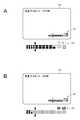
- FIG. 3A and FIG. 3Bare diagrams showing examples of display regarding the number of quantization bits.
- FIG. 4is a flowchart showing the flow of processing in the speech processing apparatus according to the first embodiment.
- FIG. 5is a block diagram showing a configuration example of the speech processing apparatus according to the second embodiment.
- FIG. 6is a block diagram showing an example of the configuration of the speech processing apparatus according to the third embodiment.
- FIG. 1is a block diagram showing a configuration example of a voice processing apparatus (voice processing apparatus 1) according to the first embodiment.
- the voice processing device 1can be applied to, for example, a device capable of recording voice, specifically, an imaging device, a smartphone, a portable recording device, a wearable device, and the like.
- the voice processing device 1includes, for example, a microphone 11 which is an example of a sound collection unit, an A / D (Analog to Digital) converter 12 which is an example of a conversion unit, and an FFT (Fast Fourier Transform) circuit 13 which is an example of a frequency analysis unit. , A digital signal processor (DSP) 14, a display unit 15, a recording unit 16, and a recording medium 17.
- DSPdigital signal processor
- the microphone 11is for collecting surrounding sound, and may be a microphone built in the voice processing device 1 or a microphone (external microphone) that is detachable from the voice processing device 1.
- the soundmay be any sound, such as music, human voice, natural sound, and the like.
- the microphone 11 according to the first embodimentis a microphone having sufficient performance for 24 quantization bit numbers to be described later.
- the microphone 11outputs, to the A / D converter 12, predetermined analog audio data corresponding to the collected sound.
- the A / D converter 12converts analog audio data supplied from the microphone 11 into digital audio data.
- the A / D converter 12samples analog voice data with two quantization bit numbers (a first quantization bit number and a second quantization bit number larger than the first quantization bit number).
- the sampling frequencyis set to an arbitrary value (for example, 96 kHz (kilohertz)).
- the first quantization bit numberis, for example, a bit number smaller than 16 bits
- the second quantization bit numberis, for example, a bit number larger than 24 bits (for example, 24 bits or 32 bits).
- the first quantization bit numberis 16 bits
- the second quantization bit numberis 24 bits.
- audio data with a sampling frequency of 96 kHz and a quantization bit number of 24 bitsmay be referred to as high res (abbreviation of high resolution).
- the A / D converter 12outputs, as digital audio data D1, first digital audio data obtained by performing AD conversion with a quantization bit number of 16 bits. Further, the A / D converter 12 outputs, as digital audio data D2, second digital audio data obtained by performing AD conversion with 24 quantization bits.
- the digital audio data D1 and D2are supplied to the FFT circuit 13.
- the digital audio data D1 and D2are branched and also supplied to the recording unit 16.
- the FFT circuit 13performs FFT on the digital voice data D1, and outputs an analysis result DF1 as a result (result in the frequency domain) to the DSP 14.
- the analysis result DF1is, for example, data to which an analysis result, an identifier indicating the digital audio data D1, and the number of quantization bits are associated. Further, the FFT circuit 13 performs FFT on the digital voice data D2, and outputs an analysis result DF2 as a result (result in the frequency domain) to the DSP 14.
- the analysis result DF2is, for example, data to which an analysis result, an identifier indicating the digital audio data D2, and the number of quantization bits are associated.
- the DSP 14controls each unit of the voice processing device 1.
- the DSP 14has a determination unit 14a as a function.
- the determination unit 14adetermines ambient environmental noise such as background noise based on the analysis results DF1 and DF2. More specifically, the determination unit 14a determines the environmental noise, and based on the determination result, it is an environment suitable for recording digital audio data in which the quantization bit number is either 16 bits or 24 bits. Determine if The environmental noise means the condition of noise around the sound collecting place (the presence or absence of noise, its level, etc.).
- the DSP 14outputs the recording control signal SG to the recording unit 16 according to the determination result of the determination unit 14a.
- the display unit 15includes a driver and a display.
- a displayLCD (Liquid Crystal Display) and organic EL (Electro Luminescence) can be illustrated.
- the display unit 15displays 16 bits and 24 bits, specifically, any of audio data sampled at 16 bits (digital audio data D1) and audio data sampled at 24 bits (digital audio data D2). Information is displayed on whether the is recorded.
- the recording unit 16is for recording digital audio data on the recording medium 17.
- the recording unit 16includes, for example, a switcher (not shown), switches an input by switching the switcher, and selectively records any one of the digital audio data D1 and D2 in the recording medium 17.
- the switcheris switched by the recording control signal SG output from the DSP 14.
- the recording medium 17may be a hard disk or the like built in the audio processing device 1 or a portable memory such as a USB (Universal Serial Bus) memory, an optical disk, or an SD card, and at least corresponds to the sound collected by the microphone 11 Any audio data can be recorded as long as it can be recorded.
- a portable memorysuch as a USB (Universal Serial Bus) memory, an optical disk, or an SD card
- the number of quantization bitsis high (for example, 24 bits) in addition to the recording of digital audio data having the number of quantization bits generally used of 16 bits.
- Digital audio datacan be recorded.
- recordingneeds to be performed under a low noise environment. If audio data of high quantization bit number is recorded under an environment where noise is not sufficiently low, the file size becomes larger than necessary and the recording time of the recording medium becomes short.
- the recorded sound sourcehas the same sound quality as the 16-bit audio data. Therefore, it is necessary to perform AD conversion using an appropriate number of quantization bits.
- FIGS. 2A and 2Bare diagrams referred to in order to explain the determination processing in the determination unit 14a.
- the higher the number of quantization bitsthe larger the resolution
- an effective effectcan not be obtained even if the number of quantization bits is increased.
- the horizontal axisrepresents frequency
- the vertical axisrepresents level.
- the environmental noise collected by the microphone 11 in the frequency domain(pure noise component) is schematically shown by a dotted line L0.
- the environmental noise indicated by the dotted line L0is sampled with 16 quantization bits, and the result of FFT analysis thereof is schematically shown by a solid line L1.
- the environmental noise indicated by the dotted line L0is sampled with 24 quantization bits, and the result of FFT analysis thereof is schematically shown by the solid line L2.
- the solid line L1indicates the performance limit when the number of quantization bits is 16 bits, and in the case of noise lower in level than the solid line L1 (noise at a level located on the lower side in the graph), the noise is Even if AD conversion is performed by bits, an analysis result that substantially matches the solid line L1 is obtained.
- the solid line L2indicates the performance limit when the number of quantization bits is 24 bits, and in the case of noise lower in level than the solid line L2 (noise at the level located graphically lower) Even if noise is AD converted with 24 bits, an analysis result that substantially matches the solid line L2 is obtained.
- the determination unit 14adetermines that setting the number of quantization bits to 24 bits is an appropriate environment. .
- FIG. 2Bthe case where environmental noise is large (when the level of dotted line L0 exceeds the solid lines L1 and L2) is considered.
- a relatively large environmental noise having a frequency characteristic such as dotted line L0 shown in FIG. 2Bis sampled with 16 quantization bits and it is subjected to FFT analysis by FFT circuit 13, the result is Substantially coincides with the dotted line L0.
- relatively large environmental noise having a frequency characteristic such as dotted line L0is sampled with 24 quantization bits, and it is subjected to FFT analysis by the FFT circuit 13, the result substantially matches the dotted line L0 Do.
- the determination unit 14adetermines that setting the number of quantization bits to 16 bits is an appropriate environment.
- the determination unit 14asamples two digital audio data with different numbers of quantization bits, and determines whether there is a difference between the results of the frequency analysis performed on each of them. To determine the environment for voice recording. For example, frequency analysis is performed on each of the digital audio data D1 and D2 in real time, and the difference between the analysis results DF1 and DF2 as a result thereof is determined and integrated.
- the determination unit 14adetermines that there is no difference between the analysis results DF1 and DF2, and the analysis result If the difference between DF1 and DF2 is equal to or greater than a predetermined threshold value, it is determined that there is a difference between the analysis results DF1 and DF2. If there is no difference, the DSP 14 outputs the recording control signal SG for recording the digital audio data D1 corresponding to the quantization bit number 16 to the recording unit 16.
- the switch controlis controlled by the recording control signal SG such that the input is digital audio data D1.
- the recording unit 16records the digital audio data D1 on the recording medium 17.
- the DSP 14When there is a difference, the DSP 14 outputs, to the recording unit 16, a recording control signal SG for recording the digital audio data D2 whose number of quantization bits corresponds to 24 bits.
- the switch controlis controlled by the recording control signal SG so that the input is digital audio data D2.
- the recording unit 16records the digital audio data D2 on the recording medium 17.
- FIGS. 3A and 3Bare display examples showing whether the number of quantization bits of digital audio data to be recorded is 16 bits or 24 bits.
- the character 21 of "Hi-bit"is displayed at the right corner of the display unit 15 (note that in FIGS. 3A and 3B, the character 21 displayed on the display unit 15 below the figure showing the display unit 15). Etc.).
- the character 21is colored and displayed as shown in FIG. 3B.
- the color of the characters 21may be blue or any other color.
- the character 21may be blinked, or the character 21 may be displayed only when the number of quantization bits of the digital audio data to be recorded is 24 bits.
- a plurality of rectangles and two trianglesmay be displayed below the display of the character "Hi-bit".
- the plurality of rectanglesare displayed side by side in, for example, two upper and lower lines.
- the upper and lower rectangular columnsfor example, the two upper and lower rectangular frames located at the rightmost position are displayed in red, and the upper and lower four rectangular frames located at the second and third from the right are displayed. It is displayed in yellow, and the other rectangular frames are displayed in green.
- the size of the rectangle on the left side(for example, four columns on the left side (eight pieces)) is slightly smaller than the other rectangles.
- the two trianglesare displayed in blue so as to indicate between predetermined rectangles.
- the color of these rectanglesis an example, and is not limited to the illustrated colors.
- the rectangular framerepresents the level of the audio signal.
- the inside of each rectangleis colored in the same color as the frame according to the level of the audio signal. As the level of the audio signal is higher, the right rectangle is colored.
- the red boxed rectanglesrepresent the upper limit of the level, the yellow rectangles represent larger levels, and the green rectangles represent safe levels.
- the small size of the rectangle on the left sideindicates that the area of the audio signal is small.
- the trianglecorresponds to the solid line L1 shown in FIG. 2A and FIG. 2B, and when converting the FFT in the case of 16 bits to the signal level, “Hi-bit” is used for a signal smaller than the triangle mark.
- the letter of the symbolshows the indication that it is displayed colored.
- the level of the audio signalmay be displayed in association with an index (standard) in which the number of quantization bits of the audio signal to be recorded is 16 bits. This allows the user to intuitively recognize the number of quantization bits to be applied according to the level of the input audio signal.
- the indication regarding the number of quantization bitsmay be a presentation of the number of quantization bits appropriate for environmental noise in the recording environment (the number of recommended quantization bits).
- the setting of the number of quantization bitscan be performed by an operation input unit such as a button provided on the audio processing device 1 or a touch screen.
- the useroperates the operation input unit with reference to the displayed recommended number of quantization bits to select the number of quantization bits (for example, the number of quantization bits displayed as the recommendation) in the speech processing apparatus 1. It may be settable.
- the display modemay be a character other than the characters "Hi-bit", may be a figure such as a bar instead of a character, or may be a combination of a character and a figure.
- the notificationis not limited to display, and may be notification by light such as lighting of an LED (Light Emitting Diode), notification by voice, notification by vibration, notification by combining these, and the like.
- step ST11sound collection by the microphone 11 is started.
- the timing at which the microphone 11 starts sound collectioncan be made appropriate.
- the microphone 11may start sound collection at a timing before recording (for example, a timing at which the audio processing device 1 is activated).
- the voice processing device 1is applied to a recording device or an imaging device, the microphone 11 may start sound collection at the timing when the recording or the recording is started.
- the microphone 11outputs analog audio data corresponding to the collected sound to the A / D converter 12. Then, the process proceeds to step ST12.
- step ST12the A / D converter 12 AD converts analog audio data.
- the A / D converter 12samples analog audio data with 16 quantization bits to obtain digital audio data D1.
- the A / D converter 12samples analog audio data with 24 quantization bits to obtain digital audio data D2.
- the two AD conversion processesare performed, for example, in parallel.
- audio data in stereo formattwo channels
- AD conversion with different numbers of quantization bitsis performed on each of LR (Left / Right) audio data.
- the A / D converter 12outputs the digital audio data D1 and D2 to the FFT circuit 13 and the recording unit 16, respectively. Then, the process proceeds to step ST13.
- step ST13FFT analysis is performed.
- the FFT circuit 13performs FFT on each of the digital voice data D1 and D2, and obtains the analysis results DF1 and DF2 as the result.
- the FFT circuit 13outputs the analysis results DF1 and DF2 to the DSP 14. Then, the process proceeds to step ST14.
- step ST14the determination unit 14a of the DSP 14 compares the analysis results DF1 and DF2 and determines whether there is a difference between the two, thereby making a determination regarding the noise component. If there is no difference between the two, in other words, if no reduction in the noise component is observed even if the number of quantization bits is 16 or 24 bits, the process proceeds to step ST15.
- step ST15the DSP 14 sets the recording target to digital audio data (digital audio data D1) having a quantization bit number of 16 bits. Then, the process proceeds to step ST17.
- step ST16the DSP 14 sets the recording target to digital audio data (digital audio data D2) having a quantization bit number of 24 bits. Then, the process proceeds to step ST17.
- step ST17the DSP 14 outputs the recording control signal SG according to the determination result of the determination unit 14a to the recording unit 16.
- the inputis switched by the recording control signal SG, and one of the digital audio data D1 and D2 is recorded on the recording medium 17 by the recording unit 16. Then, the process proceeds to step ST18.
- step ST18notification regarding the number of quantization bits is performed. For example, as described with reference to FIG. 3, information on the number of quantization bits of digital audio data being recorded is displayed. The above-described processing is repeated for a predetermined period (for example, a period during recording or recording).
- a modecan be selected automatically or by the user to increase the number of quantization bits only when an effective effect is obtained. This makes it possible to avoid wasteful consumption of memory capacity due to the setting of a high number of quantization bits even when effective effects can not be obtained.
- writing to a recording medium with a low writing speedmay be possible by lowering the recording rate.
- the second embodimentis an embodiment in which the determination unit 14a of the DSP 14 determines the performance of the microphone. Microphone performance may include noise performance referred to as self noise level.
- FIG. 5is a view showing a configuration example of a voice processing device (voice processing device 2) according to the second embodiment.
- the voice processing device 2differs from the voice processing device 1 in that the microphone 11 is an external microphone 11 a that is attached to and detached from the voice processing device 2.
- the external microphone 11ait is assumed that the performance is unknown, or one that presents a certain noise performance but it is unknown whether it actually has the performance.
- the basic operation of the speech processing device 2is the same as that of the speech processing device 1.
- analog audio data collected by the external microphone 11 ais supplied to the A / D converter 12.
- the A / D converter 12performs analog-to-digital conversion on analog audio data with the number of quantization bits of 16 bits and 24 bits to obtain digital audio data D1 and D2.
- the FFT circuit 13performs FFT on the digital audio data D1 and D2, and the analysis results DF1 and DF2 as the result are supplied to the determination unit 14a.
- the dotted line L0 shown in FIG. 2can be replaced with a noise component based on the noise performance of the external microphone 11a in the second embodiment.
- the level of the noise componentdecreases (for example, the dotted line L0 in FIG. 2A).
- a differenceoccurs between the analysis results DF1 and DF2.
- the external microphone 11ais not excellent in noise performance, the noise superimposed on the sound to be collected becomes large, and the noise component becomes large (for example, dotted line L0 in FIG. 2B).
- There is no difference between the analysis results DF1 and DF2the difference is less than the threshold).
- the determination unit 14adetermines that the external microphone 11a is excellent in noise performance, and the digital audio data D1 having a quantization bit number of 24 bits. And outputs a recording control signal SG for recording to the recording unit 16.
- the determination unit 14adetermines that the external microphone 11a is not excellent in noise performance, and the digital audio data having a quantization bit number of 16 bits.
- a recording control signal SG for recording D2is output to the recording unit 16. The input is switched by the recording control signal SG.
- the recording unit 16records one of the digital audio data D1 and D2 on the recording medium 17.
- notification according to the second embodimentmay be performed.
- a notification that the performance of the external microphone 11a is equal to or higher than a certain level or that the performance of the external microphone 11a is inferior to a certain levelmay be displayed or the like.
- the second embodiment described aboveit is possible to determine the performance of the microphone connected to the voice processing device, and to record digital voice data based on the appropriate number of quantization bits according to the determination result. .
- the same effect as that of the first embodimentcan be obtained.
- FIG. 6is a block diagram showing a configuration example of a voice processing apparatus (voice processing apparatus 3) according to the third embodiment.
- the voice processing device 3has a microphone 11 and an external microphone 11a.
- the other configurationsare the same as the voice processing devices 1 and 2.
- the microphone 11is a microphone that the speech processing device 3 has, and as described above, is a microphone that has sufficient performance for 24 quantization bits.
- the external microphone 11ait is assumed that the performance is unknown, or one that presents a certain noise performance but it is unknown whether it actually has the performance.
- the input from the microphone 11 and the input from the external microphone 11acan be switched by, for example, the user's operation.
- Analog audio data collected by the microphone 11is supplied to the A / D converter 12.
- the A / D converter 12performs A / D conversion on the analog audio data by sampling each quantization bit number of 16 bits and 24 bits to obtain digital audio data D1 and D2.
- analog audio data collected by the external microphone 11 ais supplied to the A / D converter 12.
- the A / D converter 12performs A / D conversion on the analog audio data by sampling each quantization bit number of 16 bits and 24 bits to obtain digital audio data D3 and D4.
- Digital audio data D1 to D4are input to the recording unit 16 in the third embodiment.
- One of the four inputsis selected by a switcher (not shown), and the digital audio data of the selected input is recorded on the recording medium 17 by the recording unit 16.
- Digital voice data D1 to D4are supplied to the FFT circuit 13.
- the FFT circuit 13performs FFT on each of the digital voice data D1 to D4 and obtains analysis results DF1 to DF4 as the result.
- the analysis results DF1 to DF4are supplied to the DSP.
- the determination unit 14a of the DSP 14determines the magnitude of the environmental noise based on the analysis results DF1 and DF2 as in the first embodiment. Further, the determination unit 14a determines the performance of the external microphone 11a based on the analysis results DF3 and DF4 as in the second embodiment. The process of determining the environmental noise and the performance of the microphone may be performed in time series or in parallel.
- the determination result by the determination unit 14acan be classified into, for example, the following four patterns.
- Pattern AIn the case where environmental noise is small and the performance of the external microphone 11a is above a certain level.
- Pattern BThe environmental noise is small, but the performance of the external microphone 11a is less than a certain level.
- Pattern CWhen environmental noise is large and the performance of the external microphone 11a is equal to or higher than a predetermined level.
- Pattern DEnvironmental noise is high and the performance of the external microphone 11a is less than a certain level.
- the DSP 14sets the recording target to the digital audio data D2 or the digital audio data D4 whose quantization bit number is 24 bits. Which one of the digital audio data D2 and D4 is to be recorded is determined according to, for example, the setting of the input by the user.
- the DSP 14outputs the recording control signal SG to the recording unit 16.
- the switcheris switched by the recording control signal SG, and one of the digital audio data D2 and D4 is recorded on the recording medium 17.
- the DSP 14sets digital audio data to be recorded on the recording medium 17 according to the setting regarding the microphone to be used. For example, when the microphone 11 is set as a microphone to be used, one of the digital audio data D1 and D2 is to be recorded. In the case of pattern B, since the environmental noise is small, the DSP 14 sets the digital audio data D2 as a recording target, and outputs a recording control signal SG corresponding to the setting to the recording unit 16. The switcher is switched according to the recording control signal SG, and the digital audio data D2 is recorded on the recording medium 17 by the recording unit 16.
- the DSP 14sets the digital audio data D3 as a recording target, and outputs a recording control signal SG corresponding to the setting to the recording unit 16.
- the switcheris switched according to the recording control signal SG, and the digital audio data D3 is recorded on the recording medium 17 by the recording unit 16.
- the DSP 14sets the digital audio data D1 as a recording target when the microphone 11 is set as a microphone to be used, and outputs a recording control signal SG corresponding to the setting to the recording unit 16.
- the switcheris switched according to the recording control signal SG, and the digital audio data D1 is recorded on the recording medium 17 by the recording unit 16.
- the DSP 14sets the digital audio data D3 as a recording target, and outputs the recording control signal SG corresponding to the setting to the recording unit 16.
- the switcheris switched according to the recording control signal SG, and the digital audio data D3 is recorded on the recording medium 17 by the recording unit 16.
- the processis similar to that of the pattern C because the environmental noise is large.
- the microphone 11is set as a microphone to be used
- the digital audio data D1is recorded on the recording medium 17.
- digital audio data D 3is recorded on the recording medium 17.
- notification on the number of quantization bits and notification on the performance of the microphonemay be performed.
- the audio processing apparatusmay not have the display unit.
- the display unitmay be connectable to the voice processing device wirelessly or by wire.
- the audio processing apparatusmay not have the recording unit and the recording medium.
- digital audio data corresponding to the determination result of the determination unitmay be transmitted to another device (for example, a cloud server or a personal computer) existing on the network via the communication unit.
- the recording processmay be performed by the recording unit of the other apparatus.
- the microphone and the A / D convertermay be connected by wire or may be connected by wireless.
- the audio processing apparatusmay be configured to have a number of A / D converters corresponding to the pattern of the number of quantization bits (for example, two patterns of 16 bits and 24 bits). Then, the DSP may perform control to operate only the A / D converter corresponding to the determination result of the determination unit. Thereby, the amount of data transmitted in the voice processing device can be reduced.
- the recording unitmay record all of the plurality of input digital audio data on a recording medium. Then, for example, after the user actually listens to the voice obtained by demodulating the digital voice data, the voice data may be appropriately deleted and stored.
- each of the above-described embodimentscan be realized in any form, such as a method, a program, or a recording medium recording the program. Also, the program may be downloadable. Then, the functions described in each embodiment may be realized by another apparatus (for example, an imaging apparatus or a smartphone) downloading and installing the program.
- another apparatusfor example, an imaging apparatus or a smartphone
- the present disclosurecan also adopt the following configurations.
- the predetermined audio datais sampled with a first number of quantization bits and a second number of quantization bits larger than the first number of quantization bits, and the respective results are obtained as first and second digital audio data.
- a converterthat outputs as A frequency analysis unit that performs frequency analysis on each output from the conversion unit;
- a determination unitthat performs a predetermined determination process based on an analysis result by the frequency analysis unit.
- the audio processing devicefurther including: a recording unit that selectively records the first and second digital audio data on a recording medium based on the determination result by the determination unit.
- the recording unitis When there is no difference between the result of the frequency analysis of the first digital audio data and the result of the frequency analysis of the second digital audio data, the first digital audio data does not have a difference greater than or equal to a threshold. Digital audio data on the recording medium, If there is a difference between the result of frequency analysis of the first digital audio data and the result of frequency analysis of the second digital audio data, the difference is greater than the threshold value.
- the audio processing deviceaccording to (2), wherein 2 digital audio data is recorded on the recording medium.
- the voice processing apparatusaccording to any one of (1) to (3), further including a notification unit that performs notification on the first and second quantization bit numbers according to the determination result by the determination unit.
- the voice processing devicefurther including a display unit that performs the notification by display.
- the display unitdisplays whether the number of quantization bits of digital audio data to be recorded is either the number of first quantization bits or the number of second quantization bits.
- Processing unit(7)
- the audio processing devicewherein the display unit displays a level distribution of audio data and an index to which the first number of quantization bits is applied in association with each other.
- the voice processing apparatusaccording to any one of (1) to (7), wherein the determination unit determines environmental noise based on an analysis result by the frequency analysis unit.
- the voice processing apparatusaccording to any one of (1) to (8), wherein the determination unit determines the performance of the sound collection unit based on an analysis result by the frequency analysis unit.
- the voice processing apparatusaccording to any one of (1) to (9), further including a sound collection unit that collects a voice corresponding to the predetermined voice data.
- the sound processing unitaccording to (10), wherein the sound collection unit is at least one of a built-in and an externally connected microphone.
- (13) The speech processing apparatuswherein the first number of quantization bits is 16 bits, and the second number of quantization bits is 24 bits or 32 bits.
- the conversion unitperforms sampling on predetermined audio data with a first number of quantization bits and a second number of quantization bits larger than the first number of quantization bits, and the respective results are first and second Output as digital audio data of
- a frequency analysis unitperforms frequency analysis on each output from the conversion unit;
- a voice processing methodwherein a determination unit performs a predetermined determination process based on an analysis result by the frequency analysis unit.
- the conversion unitperforms sampling on predetermined audio data with a first number of quantization bits and a second number of quantization bits larger than the first number of quantization bits, and the respective results are first and second Output as digital audio data of
- a frequency analysis unitperforms frequency analysis on each output from the conversion unit;
- a programthat causes a computer to execute an audio processing method in which a determination unit performs a predetermined determination process based on an analysis result by the frequency analysis unit.
Landscapes
- Engineering & Computer Science (AREA)
- Physics & Mathematics (AREA)
- Spectroscopy & Molecular Physics (AREA)
- Computational Linguistics (AREA)
- Signal Processing (AREA)
- Health & Medical Sciences (AREA)
- Audiology, Speech & Language Pathology (AREA)
- Human Computer Interaction (AREA)
- Acoustics & Sound (AREA)
- Multimedia (AREA)
- Quality & Reliability (AREA)
- Signal Processing For Digital Recording And Reproducing (AREA)
Abstract
Translated fromJapaneseDescription
Translated fromJapanese本開示は、音声処理装置、音声処理方法及びプログラムに関する。The present disclosure relates to an audio processing device, an audio processing method, and a program.
技術の進展に伴い、より高い量子化ビット(bit)数でサンプリングする(量子化する)ことにより得られる音声データが記録されるようになってきている(例えば、特許文献1を参照のこと)。With advances in technology, audio data obtained by sampling (quantizing) with a higher number of quantization bits has been recorded (see, for example, Patent Document 1). .
このような分野では、周囲の環境等に応じて適切な量子化ビット数でサンプリングが行われることが望ましい。In such a field, it is desirable that sampling be performed with an appropriate number of quantization bits according to the surrounding environment and the like.
したがって、本開示は、周囲の環境等に応じて適切な量子化ビット数でサンプリングを行うことができる音声処理装置、音声処理方法及びプログラムを提供することを目的の一つとする。Therefore, an object of the present disclosure is to provide an audio processing device, an audio processing method, and a program that can perform sampling with an appropriate number of quantization bits according to the surrounding environment and the like.
本開示は、例えば、
所定の音声データに対して第1の量子化ビット数及び第1の量子化ビット数より大きい第2の量子化ビット数でサンプリングを行い、それぞれの結果を第1及び第2のデジタル音声データとして出力する変換部と、
変換部からのそれぞれの出力に対して周波数解析を行う周波数解析部と、
周波数解析部による解析結果に基づいて所定の判定処理を行う判定部と
を有する音声処理装置である。The present disclosure is, for example,
Sampling is performed on predetermined audio data with a first quantization bit number and a second quantization bit number larger than the first quantization bit number, and the respective results are used as first and second digital audio data. A converter that outputs
A frequency analysis unit that performs frequency analysis on each output from the conversion unit;
And a determination unit that performs a predetermined determination process based on an analysis result by the frequency analysis unit.
また、本開示は、例えば、
変換部が、所定の音声データに対して第1の量子化ビット数及び第1の量子化ビット数より大きい第2の量子化ビット数でサンプリングを行い、それぞれの結果を第1及び第2のデジタル音声データとして出力し、
周波数解析部が、変換部からのそれぞれの出力に対して周波数解析を行い、
判定部が、周波数解析部による解析結果に基づいて所定の判定処理を行う
音声処理方法である。Also, the present disclosure is, for example,
The converter performs sampling on predetermined audio data with a first number of quantization bits and a second number of quantization bits larger than the first number of quantization bits, and outputs the respective results as first and second results. Output as digital audio data,
The frequency analysis unit performs frequency analysis on each output from the conversion unit,
The determination unit is an audio processing method that performs predetermined determination processing based on an analysis result by the frequency analysis unit.
また、本開示は、例えば、
変換部が、所定の音声データに対して第1の量子化ビット数及び第1の量子化ビット数より大きい第2の量子化ビット数でサンプリングを行い、それぞれの結果を第1及び第2のデジタル音声データとして出力し、
周波数解析部が、変換部からのそれぞれの出力に対して周波数解析を行い、
判定部が、周波数解析部による解析結果に基づいて所定の判定処理を行う
音声処理方法をコンピュータに実行させるプログラムである。Also, the present disclosure is, for example,
The converter performs sampling on predetermined audio data with a first number of quantization bits and a second number of quantization bits larger than the first number of quantization bits, and outputs the respective results as first and second results. Output as digital audio data,
The frequency analysis unit performs frequency analysis on each output from the conversion unit,
The determination unit is a program that causes a computer to execute an audio processing method that performs predetermined determination processing based on an analysis result by the frequency analysis unit.
本開示の少なくとも実施形態によれば、周囲の環境等に応じて適切な量子化ビット数でサンプリングを行うことができる。なお、ここに記載された効果は必ずしも限定されるものではなく、本開示中に記載されたいずれの効果であってもよい。また、例示された効果により本開示の内容が限定して解釈されるものではない。According to at least an embodiment of the present disclosure, sampling can be performed with an appropriate number of quantization bits according to the surrounding environment and the like. In addition, the effect described here is not necessarily limited, and may be any effect described in the present disclosure. Further, the contents of the present disclosure should not be interpreted as being limited by the exemplified effects.
以下、本開示の実施形態等について図面を参照しながら説明する。なお、説明は以下の順序で行う。
<1.第1の実施形態>
<2.第2の実施形態>
<3.第3の実施形態>
<4.変形例>
以下に説明する実施形態等は本開示の好適な具体例であり、本開示の内容がこれらの実施形態等に限定されるものではない。Hereinafter, embodiments of the present disclosure and the like will be described with reference to the drawings. The description will be made in the following order.
<1. First embodiment>
<2. Second embodiment>
<3. Third embodiment>
<4. Modified example>
The embodiments and the like described below are preferable specific examples of the present disclosure, and the contents of the present disclosure are not limited to these embodiments and the like.
<1.第1の実施形態>
[音声処理装置の構成例]
図1は、第1の実施形態に係る音声処理装置(音声処理装置1)の構成例を示すブロック図である。音声処理装置1は、例えば、音声を記録可能な機器、具体的には、撮像装置、スマートフォン、可搬型の録音機器、ウェアラブル機器等に適用され得る。<1. First embodiment>
[Configuration Example of Voice Processing Device]
FIG. 1 is a block diagram showing a configuration example of a voice processing apparatus (voice processing apparatus 1) according to the first embodiment. The voice processing device 1 can be applied to, for example, a device capable of recording voice, specifically, an imaging device, a smartphone, a portable recording device, a wearable device, and the like.
音声処理装置1は、例えば、集音部の一例であるマイクロフォン11、変換部の一例であるA/D(Analog to Digital)コンバータ12、周波数解析部の一例であるFFT(Fast Fourier Transform)回路13、DSP(Digital Signal Processor)14、表示部15、記録部16及び記録媒体17を有している。The voice processing device 1 includes, for example, a
マイクロフォン11は、周囲の音声を集音するものであり、音声処理装置1に内蔵されるマイクロフォンのでも良いし、音声処理装置1に着脱自在とされるマイクロフォン(外部マイクロフォン)でも良い。音声は、音楽、人の声、自然音等、音であれば何でも良い。第1の実施形態に係るマイクロフォン11は、後述する量子化ビット数24ビットに対して十分な性能を有するマイクロフォンである。マイクロフォン11は、集音した音声に対応する所定のアナログ音声データをA/Dコンバータ12に出力する。The microphone 11 is for collecting surrounding sound, and may be a microphone built in the voice processing device 1 or a microphone (external microphone) that is detachable from the voice processing device 1. The sound may be any sound, such as music, human voice, natural sound, and the like. The
A/Dコンバータ12は、マイクロフォン11から供給されるアナログ音声データをデジタル音声データに変換する。A/Dコンバータ12は、2つの量子化ビット数(第1の量子化ビット数及び第1の量子化ビット数より大きい第2の量子化ビット数)でアナログ音声データをサンプリングする。なお、サンプリング周波数は、任意の値(例えば、96kHz(キロヘルツ))に設定される。第1の量子化ビット数は例えば16ビットより小さいビット数であり、第2の量子化ビット数は例えば24ビットより大きいビット数(例えば、24ビットや32ビット)である。実施形態では、第1の量子化ビット数を16ビット、第2の量子化ビット数を24ビットとして説明する。なお、サンプリング周波数96kHz、量子化ビット数24ビットの音声データは、ハイレゾ(ハイレゾルーションの略)と称されることもある。The A /
A/Dコンバータ12は、量子化ビット数16ビットでAD変換することにより得られる第1のデジタル音声データをデジタル音声データD1として出力する。また、A/Dコンバータ12は、量子化ビット数24ビットでAD変換することにより得られる第2のデジタル音声データをデジタル音声データD2として出力する。デジタル音声データD1、D2は、FFT回路13に供給される。また、デジタル音声データD1、D2は分岐され、記録部16にも供給される。The A /
FFT回路13は、デジタル音声データD1に対してFFTを行い、その結果(周波数領域の結果)である解析結果DF1をDSP14に出力する。解析結果DF1は、例えば、解析結果、デジタル音声データD1を示す識別子、量子化ビット数が対応付けられたデータである。また、FFT回路13は、デジタル音声データD2に対してFFTを行い、その結果(周波数領域の結果)である解析結果DF2をDSP14に出力する。解析結果DF2は、例えば、解析結果、デジタル音声データD2を示す識別子、量子化ビット数が対応付けられたデータである。The
DSP14は、音声処理装置1の各部を制御する。DSP14は、機能として判定部14aを有している。第1の実施形態に係る判定部14aは、解析結果DF1及びDF2に基づいて、暗騒音等、周囲の環境ノイズを判定する。より具体的には、判定部14aは、環境ノイズを判定し、その判定結果に基づいて、量子化ビット数が16ビット及び24ビットのどちらのデジタル音声データを記録するのに適した環境であるかを判定する。なお、環境ノイズとは、集音場所の周囲におけるノイズの状況(ノイズの有無やそのレベル等)を意味する。DSP14は、判定部14aの判定結果に応じて、記録制御信号SGを記録部16に出力する。The
表示部15は、ドライバ及びディスプレイを含む。ディスプレイとしては、LCD(Liquid Crystal Display)や有機EL(Electro Luminescence)を例示することができる。表示部15には、16ビット及び24ビットに関する表示、具体例としては、16ビットでサンプリングされた音声データ(デジタル音声データD1)及び24ビットでサンプリングされた音声データ(デジタル音声データD2)の何れが記録されているのかに関する情報が表示される。The
記録部16は、記録媒体17にデジタル音声データを記録するものである。記録部16は、例えば図示しないスイッチャを備え、スイッチャを切り替えることにより入力を切り替え、デジタル音声データD1、D2の何れかを選択的に記録媒体17に記録する。スイッチャは、DSP14が出力する記録制御信号SGによって切り替えられる。The
記録媒体17は、音声処理装置1に内蔵されるハードディスク等でも良いし、USB(Universal Serial Bus)メモリ、光ディスク、SDカード等の可搬型メモリでも良く、少なくともマイクロフォン11により集音された音に対応する音声データを記録できるものであれば何でも良い。The
[音声データを記録する際に考慮すべき問題]
ここで、音声データを記録する際に考慮すべき問題について説明する。上述したように、本実施形態に係る音声処理装置では、一般的に用いられている量子化ビット数が16ビットのデジタル音声データの記録に加え、量子化ビット数が高い(例えば、24ビット)デジタル音声データの記録が可能とされている。このような高い量子化ビット数によるAD変換を効果的に用いるためには、低ノイズの環境下で記録を行う必要がある。充分に低ノイズでない環境下で高い量子化ビット数の音声データの記録を行うと、ファイルサイズが必要以上に大きくなり、且つ、記録媒体の記録時間が短くなる。その一方で、収録された音源は、16ビットの音声データと大きく変わらない音質となる。従って、適切な量子化ビット数を用いてAD変換を行う必要がある。以上の点を踏まえ、本開示の実施形態について更に説明する。[Problems to consider when recording audio data]
Here, problems to be considered when recording audio data will be described. As described above, in the audio processing apparatus according to the present embodiment, the number of quantization bits is high (for example, 24 bits) in addition to the recording of digital audio data having the number of quantization bits generally used of 16 bits. Digital audio data can be recorded. In order to use AD conversion with such a high number of quantization bits effectively, recording needs to be performed under a low noise environment. If audio data of high quantization bit number is recorded under an environment where noise is not sufficiently low, the file size becomes larger than necessary and the recording time of the recording medium becomes short. On the other hand, the recorded sound source has the same sound quality as the 16-bit audio data. Therefore, it is necessary to perform AD conversion using an appropriate number of quantization bits. Based on the above points, the embodiment of the present disclosure will be further described.
[判定部の処理]
図2A及び図2Bは、判定部14aにおける判定処理を説明するために参照する図である。一般的に、量子化ビット数が高い(大きい)ほど音の大きさ方向の分解能が高いので、ノイズに埋もれるような音声信号に対する記録能力に優れている。しかしながら、上述したように、環境ノイズが大きい場合には量子化ビット数を高くしても有効な効果を得ることができない。[Processing of judgment unit]
FIGS. 2A and 2B are diagrams referred to in order to explain the determination processing in the
図2A、図2Bのグラフにおいて、横軸は周波数を示し、縦軸はレベルを示している。例えば、マイクロフォン11により集音された環境ノイズを周波数領域で表したもの(純粋なノイズ成分)が点線L0により模式的に示されている。点線L0で示される環境ノイズを量子化ビット数16ビットでサンプリングし、それをFFT回路13でFFT解析した結果が実線L1により模式的に示されている。点線L0で示される環境ノイズを量子化ビット数24ビットでサンプリングし、それをFFT回路13でFFT解析した結果が実線L2により模式的に示されている。実線L1は、量子化ビット数が16ビットの場合の性能限界を意味しており、実線L1よりレベル的に低いノイズ(グラフ的に下側に位置するレベルのノイズ)の場合、当該ノイズを16ビットでAD変換しても実線L1と略一致する解析結果となる。一方で、実線L2は、量子化ビット数が24ビットの場合の性能限界を意味しており、実線L2よりレベル的に低いノイズ(グラフ的に下側に位置するレベルのノイズ)の場合、当該ノイズを24ビットでAD変換しても実線L2と略一致する解析結果となる。In the graphs of FIGS. 2A and 2B, the horizontal axis represents frequency, and the vertical axis represents level. For example, the environmental noise collected by the
ここで、点線L0のような周波数特性を有する比較的小さい環境ノイズを、量子化ビット数16ビットでサンプリングし、それをFFT回路13でFFT解析した場合には、その結果は実線L1と略一致する。一方で、点線L0のような周波数特性を有する比較的小さい環境ノイズを、量子化ビット数24ビットでサンプリングし、それをFFT回路13でFFT解析した場合には、その結果は点線L0と略一致する。Here, when a relatively small environmental noise having a frequency characteristic such as dotted line L0 is sampled with 16 quantization bits, and it is subjected to FFT analysis by the
このように、環境ノイズが小さい場合には、量子化ビット数16ビットでAD変換したデジタル音声データに対して周波数解析を行った結果と、量子化ビット数24ビットでAD変換したデジタル音声データに対して周波数解析を行った結果との間に、差分が生じる。即ち、2つの周波数解析の結果の間でノイズ成分の減少が見られることから、この場合には、量子化ビット数を24ビットに設定した方が適切な環境であると判定部14aは判定する。As described above, when the environmental noise is small, the result of frequency analysis of digital audio data that has been A / D converted with 16 quantization bits and digital audio data that has been A / D converted with 24 quantization bits There is a difference between the result of frequency analysis and the result. That is, since a decrease in noise components is observed between the results of the two frequency analysis, in this case, the
一方、図2Bに示すように、環境ノイズが大きい場合(点線L0のレベルが実線L1、L2を上回る場合)を考える。この場合には、図2Bに示す点線L0のような周波数特性を有する比較的大きい環境ノイズを、量子化ビット数16ビットでサンプリングし、それをFFT回路13でFFT解析した場合には、その結果は点線L0と略一致する。一方で、点線L0のような周波数特性を有する比較的大きい環境ノイズを、量子化ビット数24ビットでサンプリングし、それをFFT回路13でFFT解析した場合には、その結果は点線L0と略一致する。On the other hand, as shown to FIG. 2B, the case where environmental noise is large (when the level of dotted line L0 exceeds the solid lines L1 and L2) is considered. In this case, if a relatively large environmental noise having a frequency characteristic such as dotted line L0 shown in FIG. 2B is sampled with 16 quantization bits and it is subjected to FFT analysis by
このように、環境ノイズが大きい場合には、量子化ビット数16ビットでAD変換したデジタル音声データにして周波数解析を行った結果と、量子化ビット数24ビットでAD変換したデジタル音声データにして周波数解析を行った結果との間に、差分が生じない。即ち、2つの周波数解析の結果の間にノイズ成分の減少が見られないことから、この場合には、細かい音声がノイズに埋もれてしまい、量子化ビット数を24ビットにしても記録するデータ量が大きくなるだけである。従って、量子化ビット数を16ビットに設定した方が適切な環境であると判定部14aは判定する。As described above, when the environmental noise is large, the result of performing frequency analysis on digital audio data converted from AD conversion with 16 quantization bits and digital audio data converted from AD conversion with 24 quantization bits There is no difference between the results of frequency analysis. That is, since no decrease in the noise component is found between the results of the two frequency analysis, in this case, the fine voice is buried in the noise, and the amount of data to be recorded even if the number of quantization bits is 24 bits Will only grow. Therefore, the
以上のように、判定部14aは、2つのデジタル音声データに対して異なる量子化ビット数でサンプリングを行い、それぞれに対して周波数解析を行った結果の間に差分が存在するか否かに応じて、音声収録における環境を判定する。例えば、リアルタイムにデジタル音声データD1、D2のそれぞれに対して周波数解析を行い、その結果である解析結果DF1、DF2の差分を求め積分する。As described above, the
そして、判定部14aは、例えば、解析結果DF1、DF2の差分(例えば、差分の積分値)が所定の閾値未満であれば、解析結果DF1、DF2の間に差分がないと判定し、解析結果DF1、DF2の差分が所定の閾値以上であれば、解析結果DF1、DF2の間に差分があると判定する。差分がない場合には、DSP14は、量子化ビット数が16ビットに対応するデジタル音声データD1を記録するための記録制御信号SGを記録部16に出力する。記録制御信号SGにより入力がデジタル音声データD1となるようにスイッチャが制御される。記録部16は、デジタル音声データD1を記録媒体17に記録する。また、差分がある場合には、DSP14は、量子化ビット数が24ビットに対応するデジタル音声データD2を記録するための記録制御信号SGを記録部16に出力する。記録制御信号SGにより入力がデジタル音声データD2となるようにスイッチャが制御される。記録部16は、デジタル音声データD2を記録媒体17に記録する。Then, if, for example, the difference between the analysis results DF1 and DF2 (for example, the integral value of the difference) is smaller than a predetermined threshold, the
[表示例]
本実施形態では、判定部14aによる判定結果に応じた、量子化ビット数に関する報知が表示によりなされる。この表示例について説明する。図3A及び図3Bに示す表示例は、記録されるデジタル音声データの量子化ビット数が16ビット及び24ビットの何れであるかを示す表示例である。例えば、表示部15の右隅に「Hi-bit」との文字21が表示される(なお、図3A及び図3Bでは、表示部15を示す図の下に表示部15に表示される文字21等を拡大して示している。)。記録されるデジタル音声データの量子化ビット数が16ビットである場合には、図3Aに示すように文字21を例えば白抜きして表示する。また、記録されるデジタル音声データの量子化ビット数が24ビットである場合には、図3Bに示すように文字21を着色して表示する。文字21の色は、青色、その他、任意の色とすることができる。また、文字21を点滅させても良いし、記録されるデジタル音声データの量子化ビット数が24ビットである場合のみに文字21を表示するようにしても良い。[Display example]
In the present embodiment, notification regarding the number of quantization bits is made by display according to the determination result by the
なお、図3A及び図3Bに示すように、「Hi-bit」との文字の表示の下側に、複数の矩形及び2個の三角が表示されても良い。複数の矩形は、例えば、上下2列に並べて表示される。上段及び下段の矩形の列において、例えば、一番右側に位置する上下2個の矩形の枠は赤色で表示され、右側から数えて2番目及び3番目に位置する上下4個の矩形の枠は黄色で表示され、その他の矩形の枠は緑色で表示される。また、左側(例えば、左側4列分(8個))の矩形の大きさは、他の矩形よりやや小さくされている。2個の三角は青色で所定の矩形同士の間を指し示すように表示される。もちろん、これらの矩形の色は一例であって、例示した色に限定されるものではない。As shown in FIGS. 3A and 3B, a plurality of rectangles and two triangles may be displayed below the display of the character "Hi-bit". The plurality of rectangles are displayed side by side in, for example, two upper and lower lines. In the upper and lower rectangular columns, for example, the two upper and lower rectangular frames located at the rightmost position are displayed in red, and the upper and lower four rectangular frames located at the second and third from the right are displayed. It is displayed in yellow, and the other rectangular frames are displayed in green. Also, the size of the rectangle on the left side (for example, four columns on the left side (eight pieces)) is slightly smaller than the other rectangles. The two triangles are displayed in blue so as to indicate between predetermined rectangles. Of course, the color of these rectangles is an example, and is not limited to the illustrated colors.
矩形の枠は、音声信号のレベルを表している。音声信号のレベルに応じて、各矩形の内側が枠と同じ色で着色される。音声信号のレベルが大きいほど、右側の矩形まで着色される。赤枠の矩形はレベルの上限を表し、黄色の矩形はレベルが大きいことを表し、緑色の矩形は安全なレベルを表している。左側の矩形の大きさが小さいのは、音声信号のレベルが小さい領域であることを表している。三角は、図2A及び図2Bに示した実線L1に対応するものであり、16ビットのときのFFTを信号レベルに変換した場合に、三角の印より小さい信号の場合に「Hi-bit」との文字が着色して表示される目安を示している。このように、音声信号のレベルと、記録される音声信号の量子化ビット数が16ビットとなる指標(目安)を対応付けて表示しても良い。これにより、入力される音声信号のレベルに応じて、適用される量子化ビット数をユーザが直感的に認識することができる。The rectangular frame represents the level of the audio signal. The inside of each rectangle is colored in the same color as the frame according to the level of the audio signal. As the level of the audio signal is higher, the right rectangle is colored. The red boxed rectangles represent the upper limit of the level, the yellow rectangles represent larger levels, and the green rectangles represent safe levels. The small size of the rectangle on the left side indicates that the area of the audio signal is small. The triangle corresponds to the solid line L1 shown in FIG. 2A and FIG. 2B, and when converting the FFT in the case of 16 bits to the signal level, “Hi-bit” is used for a signal smaller than the triangle mark. The letter of the symbol shows the indication that it is displayed colored. As described above, the level of the audio signal may be displayed in association with an index (standard) in which the number of quantization bits of the audio signal to be recorded is 16 bits. This allows the user to intuitively recognize the number of quantization bits to be applied according to the level of the input audio signal.
量子化ビット数に関する表示は、収録環境における環境ノイズに対して適切な量子化ビット数の提示(お勧めの量子化ビット数)であっても良い。例えば、量子化ビット数の設定が音声処理装置1に設けられたボタン、タッチスクリーン等の操作入力部により可能とされる。ユーザは、表示されたお勧めの量子化ビット数を参照して操作入力部を操作することにより、音声処理装置1における量子化ビット数(例えば、お勧めとして表示された量子化ビット数)を設定できるようにしても良い。The indication regarding the number of quantization bits may be a presentation of the number of quantization bits appropriate for environmental noise in the recording environment (the number of recommended quantization bits). For example, the setting of the number of quantization bits can be performed by an operation input unit such as a button provided on the audio processing device 1 or a touch screen. The user operates the operation input unit with reference to the displayed recommended number of quantization bits to select the number of quantization bits (for example, the number of quantization bits displayed as the recommendation) in the speech processing apparatus 1. It may be settable.
なお、表示の態様は「Hi-bit」との文字以外でも良いし、文字ではなくバー等の図形であっても良いし、文字及び図形を組み合わせたものであっても良い。また、表示による報知に限定されることはなく、LED(Light Emitting Diode)の点灯等の光による報知、音声による報知、振動による報知、これらを組み合わせた報知等であっても良い。The display mode may be a character other than the characters "Hi-bit", may be a figure such as a bar instead of a character, or may be a combination of a character and a figure. Further, the notification is not limited to display, and may be notification by light such as lighting of an LED (Light Emitting Diode), notification by voice, notification by vibration, notification by combining these, and the like.
[処理の流れ]
図4のフローチャートを参照して、音声処理装置1において実行される処理の流れの一例について説明する。[Flow of processing]
An example of the flow of processing executed in the speech processing device 1 will be described with reference to the flowchart of FIG. 4.
ステップST11では、マイクロフォン11による集音が開始される。マイクロフォン11が集音を開始するタイミングは適宜な、タイミングとすることができる。例えば、収録前のタイミング(例えば音声処理装置1が起動されたタイミング)でマイクロフォン11が集音を開始しても良い。また、音声処理装置1が録音装置や撮像装置に適用される場合には、録音や録画が開始されたタイミングでマイクロフォン11が集音を開始しても良い。マイクロフォン11は、集音した音声に対応するアナログ音声データをA/Dコンバータ12に出力する。そして、処理がステップST12に進む。In step ST11, sound collection by the
ステップST12では、A/Dコンバータ12がアナログ音声データをAD変換する。A/Dコンバータ12は、アナログ音声データを量子化ビット数16ビットでサンプリングして、デジタル音声データD1を得る。また、A/Dコンバータ12は、アナログ音声データを量子化ビット数24ビットでサンプリングして、デジタル音声データD2を得る。2つのAD変換処理は、例えばパラレルに行われる。なお、マイクロフォン11からステレオ形式(2チャンネル)の音声データが出力される場合には、LR(Left/Right)の音声データのそれぞれに異なる量子化ビット数によるAD変換が行われる。A/Dコンバータ12は、デジタル音声データD1、D2をFFT回路13及び記録部16のそれぞれに出力する。そして、処理がステップST13に進む。In step ST12, the A /
ステップST13では、FFT解析が行われる。FFT回路13は、デジタル音声データD1、D2のそれぞれにFFTを行い、その結果である解析結果DF1、DF2を得る。FFT回路13は、解析結果DF1、DF2をDSP14に出力する。そして、処理がステップST14に進む。At step ST13, FFT analysis is performed. The
ステップST14では、DSP14の判定部14aが解析結果DF1、DF2を比較し、両者の間に差分が存在するか否かを判定することでノイズ成分に関する判定を行う。両者に差分がない場合、換言すれば、量子化ビット数が16ビットの場合でも量子化ビット数24ビットの場合でもノイズ成分の減少が見られない場合には、処理がステップST15に進む。ステップST15では、DSP14が、記録対象を量子化ビット数が16ビットのデジタル音声データ(デジタル音声データD1)に設定する。そして、処理がステップST17に進む。In step ST14, the
一方、解析結果DF1、DF2の間に閾値以上の差分がある場合、換言すれば、量子化ビット数の相違によるノイズ成分の減少が見られる場合には、処理がステップST16に進む。ステップST16では、DSP14が、記録対象を量子化ビット数が24ビットのデジタル音声データ(デジタル音声データD2)に設定する。そして、処理がステップST17に進む。On the other hand, when there is a difference equal to or larger than the threshold value between the analysis results DF1 and DF2, in other words, when a decrease in noise component due to the difference in the number of quantization bits is observed, the process proceeds to step ST16. In step ST16, the
ステップST17では、DSP14が、判定部14aの判定結果に応じた記録制御信号SGを記録部16に出力する。記録制御信号SGにより入力が切り替えられ、デジタル音声データD1、D2の何れかが記録部16により記録媒体17に記録される。そして、処理がステップST18に進む。In step ST17, the
ステップST18では、量子化ビット数に関する報知がなされる。例えば、図3を参照して説明したように、記録されているデジタル音声データの量子化ビット数に関する情報が表示される。以上、説明した処理が、所定期間(例えば、録音や録画が行われている期間)、繰り返される。In step ST18, notification regarding the number of quantization bits is performed. For example, as described with reference to FIG. 3, information on the number of quantization bits of digital audio data being recorded is displayed. The above-described processing is repeated for a predetermined period (for example, a period during recording or recording).
[効果]
以上、説明した第1の実施形態によれば、例えば、以下の効果を得ることができる。
量子化ビット数を高くすることが可能な機器で、有効な効果が得られるときのみに量子化ビット数を高くするモードを自動で又はユーザが選択することができる。これにより、有効な効果を得られない場合でも量子化ビット数が高く設定されることによるメモリ容量の無駄な消費を避けることができる。また、量子化ビット数を低くした場合に、記録レートが下がることによって書き込み速度が低い記録媒体への書き込みが可能になり得る。[effect]
According to the first embodiment described above, for example, the following effects can be obtained.
In an apparatus capable of increasing the number of quantization bits, a mode can be selected automatically or by the user to increase the number of quantization bits only when an effective effect is obtained. This makes it possible to avoid wasteful consumption of memory capacity due to the setting of a high number of quantization bits even when effective effects can not be obtained. In addition, when the number of quantization bits is reduced, writing to a recording medium with a low writing speed may be possible by lowering the recording rate.
<2.第2の実施形態>
次に、第2の実施形態について説明する。なお、第1の実施形態で説明した事項は、特に断らない限り第2の実施形態にも適用することができ、同様、同質の構成については同一の符号を付し重複した説明を省略する。第2の実施形態は、DSP14の判定部14aがマイクロフォンの性能を判定する実施形態である。マイクロフォンの性能としては、自己雑音レベルと称される雑音性能を挙げることができる。<2. Second embodiment>
Next, a second embodiment will be described. The matters described in the first embodiment can also be applied to the second embodiment unless otherwise specified. Similarly, identical constitutions are given the same reference numerals and redundant description will be omitted. The second embodiment is an embodiment in which the
図5は、第2の実施形態に係る音声処理装置(音声処理装置2)の構成例を示す図である。音声処理装置2が音声処理装置1と異なる点は、マイクロフォン11が、音声処理装置2に着脱される外部マイクロフォン11aである点である。外部マイクロフォン11aとしてはその性能が不明、若しくは、一定のノイズ性能を提示するものの実際に当該性能を有するか不明であるものが想定される。FIG. 5 is a view showing a configuration example of a voice processing device (voice processing device 2) according to the second embodiment. The
音声処理装置2の基本的な動作は、音声処理装置1と同様である。概略的に説明すれば、外部マイクロフォン11aにより集音されたアナログ音声データがA/Dコンバータ12に供給される。A/Dコンバータ12は、アナログ音声データに対して、16ビット、24ビットの量子化ビット数でAD変換を行い、デジタル音声データD1、D2を得る。デジタル音声データD1、D2に対してFFT回路13によるFFTが行われ、その結果である解析結果DF1、DF2が判定部14aに供給される。The basic operation of the
ここで、図2に示した点線L0は、第2の実施形態では、外部マイクロフォン11aの雑音性能に基づくノイズ成分に置き換えることができる。例えば、外部マイクロフォン11aが雑音性能に優れている場合にはノイズ成分のレベルは小さくなる(例えば図2Aの点線L0)。この場合には、第1の実施形態で説明したように、解析結果DF1、DF2の間に差分が生じる。一方で、外部マイクロフォン11aが雑音性能に優れていない場合には、集音される音声に重畳されるノイズが大きくなり、ノイズ成分が大きくなる(例えば図2Bの点線L0)。解析結果DF1、DF2の間に差分が生じない(差分が閾値未満を含む)となる。Here, the dotted line L0 shown in FIG. 2 can be replaced with a noise component based on the noise performance of the
即ち、判定部14aは、解析結果DF1、DF2の間に差分がある場合には、外部マイクロフォン11aが雑音性能に優れたものであると判定し、量子化ビット数が24ビットのデジタル音声データD1を記録するための記録制御信号SGを記録部16に出力する。一方、判定部14aは、解析結果DF1、DF2の間に差分がない場合には、外部マイクロフォン11aが雑音性能に優れていないものであると判定し、量子化ビット数が16ビットのデジタル音声データD2を記録するための記録制御信号SGを記録部16に出力する。記録制御信号SGにより入力が切り替えられる。記録部16は、デジタル音声データD1、D2の何れかを記録媒体17に記録する。That is, when there is a difference between the analysis results DF1 and DF2, the
なお、第2の実施形態に応じた報知が行われても良い。例えば外部マイクロフォン11aの性能が一定以上である旨又は外部マイクロフォン11aの性能が一定レベルより劣る旨の報知が表示等によってなされても良い。In addition, notification according to the second embodiment may be performed. For example, a notification that the performance of the
以上説明した第2の実施形態によれば、音声処理装置に接続されたマイクロフォンの性能を判定し、判定結果に応じて適切な量子化ビット数に基づくデジタル音声データを記録することが可能となる。また、第1の実施形態と同様の効果が得られる。According to the second embodiment described above, it is possible to determine the performance of the microphone connected to the voice processing device, and to record digital voice data based on the appropriate number of quantization bits according to the determination result. . In addition, the same effect as that of the first embodiment can be obtained.
<3.第3の実施形態>
次に、第3の実施形態について説明する。なお、第1、第2の実施形態で説明した事項は、特に断らない限り第3の実施形態にも適用することができ、同様、同質の構成については同一の符号を付し重複した説明を省略する。第3の実施形態は、概略的には、第1の実施形態と第2の実施形態とを組み合わせた実施形態である。<3. Third embodiment>
Next, a third embodiment will be described. The matters described in the first and second embodiments can be applied to the third embodiment unless otherwise specified, and the same configuration is given the same reference numerals for duplicate configurations I omit it. The third embodiment is an embodiment that combines the first and second embodiments.
図6は、第3の実施形態に係る音声処理装置(音声処理装置3)の構成例を示すブロック図である。音声処理装置3は、マイクロフォン11及び外部マイクロフォン11aを有している。その他の構成は、音声処理装置1、2と同じである。FIG. 6 is a block diagram showing a configuration example of a voice processing apparatus (voice processing apparatus 3) according to the third embodiment. The
マイクロフォン11は、音声処理装置3が有するマイクロフォンであり、上述したように、量子化ビット数24ビットに対して十分な性能を有するマイクロフォンである。外部マイクロフォン11aとしてはその性能が不明、若しくは、一定のノイズ性能を提示するものの実際に当該性能を有するか不明であるものが想定される。なお、マイクロフォン11からの入力及び外部マイクロフォン11aからの入力は、例えばユーザの操作によって切り替えることができるように構成されている。The
音声処理装置3の動作例について説明する。マイクロフォン11により集音されたアナログ音声データがA/Dコンバータ12に供給される。A/Dコンバータ12は、当該アナログ音声データに対して、16ビット、24ビットのそれぞれの量子化ビット数でサンプリングするAD変換を行い、デジタル音声データD1、D2を得る。また、外部マイクロフォン11aにより集音されたアナログ音声データがA/Dコンバータ12に供給される。A/Dコンバータ12は、当該アナログ音声データに対して、16ビット、24ビットのそれぞれの量子化ビット数でサンプリングするAD変換を行い、デジタル音声データD3、D4を得る。An operation example of the
第3の実施形態における記録部16には、デジタル音声データD1~D4が入力される。図示しないスイッチャにより4つの入力のうち1つの入力が選択され、当該選択された入力のデジタル音声データが記録部16により記録媒体17に記録される。Digital audio data D1 to D4 are input to the
デジタル音声データD1~D4がFFT回路13に供給される。FFT回路13は、デジタル音声データD1~D4のそれぞれに対してFFTを行い、その結果である解析結果DF1~DF4を得る。解析結果DF1~DF4がDSP14に供給される。Digital voice data D1 to D4 are supplied to the
DSP14の判定部14aは、第1の実施形態と同様にして、解析結果DF1、DF2に基づいて環境ノイズの大きさを判定する。また、判定部14aは、第2の実施形態と同様にして、解析結果DF3、DF4に基づいて外部マイクロフォン11aの性能を判定する。なお、環境ノイズ及びマイクロフォンの性能を判定する処理は、時系列に行われも良いし、パラレルに行われても良い。The
判定部14aによる判定結果は、例えば、以下の4つのパターンに分類することができる。
パターンA:環境ノイズが小さく、且つ、外部マイクロフォン11aの性能が一定以上の場合。
パターンB:環境ノイズは小さいものの、外部マイクロフォン11aの性能が一定未満である場合。
パターンC:環境ノイズが大きく、且つ、外部マイクロフォン11aの性能が一定以上である場合。
パターンD:環境ノイズが大きく、且つ、外部マイクロフォン11aの性能が一定未満である場合。The determination result by the
Pattern A: In the case where environmental noise is small and the performance of the
Pattern B: The environmental noise is small, but the performance of the
Pattern C: When environmental noise is large and the performance of the
Pattern D: Environmental noise is high and the performance of the
判定部14aの判定結果がパターンAの場合は、量子化ビット数を高くすることによる有利な効果が得られる環境及びマイクロフォンの性能である。そこで、DSP14は、記録対象を量子化ビット数が24ビットであるデジタル音声データD2又はデジタル音声データD4に設定する。デジタル音声データD2、D4の何れかを記録対象にするかは、例えばユーザによる入力の設定に応じて決定される。DSP14は、記録制御信号SGを記録部16に出力する。記録制御信号SGによりスイッチャが切り替えられ、デジタル音声データD2及びD4の何れかが記録媒体17に記録される。When the determination result of the
判定部14aの判定結果がパターンBの場合は、DSP14は、使用するマイクロフォンに関する設定に応じて、記録媒体17に記録されるデジタル音声データを設定する。例えば、マイクロフォン11が使用するマイクロフォンとして設定されている場合は、デジタル音声データD1、D2の何れかが記録対象となる。パターンBの場合は環境ノイズが小さいことから、DSP14は、デジタル音声データD2を記録対象として設定し、当該設定に対応する記録制御信号SGを記録部16に出力する。記録制御信号SGに応じてスイッチャが切り替えられ、デジタル音声データD2が記録部16により記録媒体17に記録される。一方、外部マイクロフォン11aが使用するマイクロフォンとして設定されている場合は、デジタル音声データD3、D4の何れかが記録対象となる。パターンBの場合は、外部マイクロフォン11aの性能が一定未満であることから、DSP14は、デジタル音声データD3を記録対象として設定し、当該設定に対応する記録制御信号SGを記録部16に出力する。記録制御信号SGに応じてスイッチャが切り替えられ、デジタル音声データD3が記録部16により記録媒体17に記録される。When the determination result of the
判定部14aの判定結果がパターンCの場合は、環境ノイズが多いことから量子化ビット数が24ビットであるデジタル音声データを記録するメリットが少ない。このため、デジタル音声データD1、D3の何れかが記録対象となる。DSP14は、マイクロフォン11が使用するマイクロフォンとして設定されている場合は、デジタル音声データD1を記録対象として設定し、当該設定に対応する記録制御信号SGを記録部16に出力する。記録制御信号SGに応じてスイッチャが切り替えられ、デジタル音声データD1が記録部16により記録媒体17に記録される。一方、DSP14は、外部マイクロフォン11aが使用するマイクロフォンとして設定されている場合は、デジタル音声データD3を記録対象として設定し、当該設定に対応する記録制御信号SGを記録部16に出力する。記録制御信号SGに応じてスイッチャが切り替えられ、デジタル音声データD3が記録部16により記録媒体17に記録される。When the determination result of the
判定部14aの判定結果がパターンDの場合も、環境ノイズが多いことから処理はパターンCの場合と同様になる。概略的に説明すれば、マイクロフォン11が使用するマイクロフォンとして設定されている場合は、デジタル音声データD1が記録媒体17に記録される。外部マイクロフォン11aが使用するマイクロフォンとして設定されている場合は、デジタル音声データD3が記録媒体17に記録される。なお、第3の実施形態において、量子化ビット数に関する報知及びマイクロフォンの性能に関する報知が行われても良い。Even when the determination result of the
以上、説明した第3の実施形態によれば、環境ノイズ及び外部マイクロフォンの性能に応じて、適切な量子化ビット数のデジタル音声データを記録媒体に記録することができる。まだ、第1、第2の実施形態で説明した効果と同様の効果を得ることができる。As described above, according to the third embodiment described above, it is possible to record digital audio data of an appropriate number of quantization bits on the recording medium according to the environmental noise and the performance of the external microphone. Still, the same effects as the effects described in the first and second embodiments can be obtained.
<4.変形例>
以上、本開示の実施形態について具体的に説明したが、本開示の内容は上述した実施形態に限定されるものではなく、本開示の技術的思想に基づく各種の変形が可能である。<4. Modified example>
As mentioned above, although embodiment of this indication was described concretely, the contents of this indication are not limited to the embodiment mentioned above, and various modification based on the technical idea of this indication are possible.
上述した各実施形態に係る音声処理装置の構成は、適宜、変更することができる。例えば、音声処理装置が表示部を有しない構成であっても良い。表示部は、音声処理装置に無線又は有線にて接続可能なものであっても良い。また、音声処理装置が記録部及び記録媒体を有しない構成であっても良い。例えば、判定部の判定結果に対応するデジタル音声データが、通信部を介してネットワーク上に存在する他の装置(例えば、クラウドサーバやパーソナルコンピュータ)に送信されても良い。そして、当該他の装置が有する記録部により記録処理が行われても良い。また、上述した実施形態において、マイクロフォンとA/Dコンバータとの間が有線により接続されていても良いし、無線により接続されていても良い。The configuration of the speech processing apparatus according to each of the above-described embodiments can be changed as appropriate. For example, the audio processing apparatus may not have the display unit. The display unit may be connectable to the voice processing device wirelessly or by wire. Further, the audio processing apparatus may not have the recording unit and the recording medium. For example, digital audio data corresponding to the determination result of the determination unit may be transmitted to another device (for example, a cloud server or a personal computer) existing on the network via the communication unit. Then, the recording process may be performed by the recording unit of the other apparatus. In the above-described embodiment, the microphone and the A / D converter may be connected by wire or may be connected by wireless.
上述した実施形態に係る音声処理装置が、量子化ビット数のパターン(例えば、16ビット及び24ビットの2パターン)に対応した数のA/Dコンバータを有する構成であっても良い。そして、DSPが、判定部の判定結果に対応するA/Dコンバータのみを動作させる制御を行うようにしても良い。これにより、音声処理装置において伝送されるデータ量を削減することができる。The audio processing apparatus according to the above-described embodiment may be configured to have a number of A / D converters corresponding to the pattern of the number of quantization bits (for example, two patterns of 16 bits and 24 bits). Then, the DSP may perform control to operate only the A / D converter corresponding to the determination result of the determination unit. Thereby, the amount of data transmitted in the voice processing device can be reduced.
上述した実施形態に係る記録部は、入力される複数のデジタル音声データの全てを記録媒体に記録しても良い。そして、例えば、ユーザがデジタル音声データを復調した音声を実際に聴取した後に、音声データを適宜、削除、保存するようにしても良い。The recording unit according to the above-described embodiment may record all of the plurality of input digital audio data on a recording medium. Then, for example, after the user actually listens to the voice obtained by demodulating the digital voice data, the voice data may be appropriately deleted and stored.
上述した各実施形態で説明した機能は、方法、プログラム、当該プログラムを記録した記録媒体等、任意の形態で実現することができる。また、当該プログラムをダウンロード可能としても良い。そして、他の装置(例えば、撮像装置、スマートフォン)が当該プログラムをダウンロードしてインストールすることにより、各実施形態で説明した機能を実現するようにしても良い。The functions described in each of the above-described embodiments can be realized in any form, such as a method, a program, or a recording medium recording the program. Also, the program may be downloadable. Then, the functions described in each embodiment may be realized by another apparatus (for example, an imaging apparatus or a smartphone) downloading and installing the program.
上述の実施形態において挙げた構成、方法、工程、形状、材料及び数値などはあくまでも例に過ぎず、必要に応じてこれと異なる構成、方法、工程、形状、材料及び数値などを用いてもよい。上述した実施形態および変形例は、適宜組み合わせることができる。The configurations, methods, processes, shapes, materials, numerical values, and the like described in the above embodiments are merely examples, and different configurations, methods, processes, shapes, materials, numerical values, and the like may be used as needed. . The embodiments and the modifications described above can be combined as appropriate.
本開示は、以下の構成も採ることができる。
(1)
所定の音声データに対して第1の量子化ビット数及び前記第1の量子化ビット数より大きい第2の量子化ビット数でサンプリングを行い、それぞれの結果を第1及び第2のデジタル音声データとして出力する変換部と、
前記変換部からのそれぞれの出力に対して周波数解析を行う周波数解析部と、
前記周波数解析部による解析結果に基づいて所定の判定処理を行う判定部と
を有する音声処理装置。
(2)
前記判定部による判定結果に基づいて、前記第1及び第2のデジタル音声データを選択的に記録媒体に記録する記録部を有する
(1)に記載の音声処理装置。
(3)
前記記録部は、
前記第1のデジタル音声データに対して周波数解析を行った結果と前記第2のデジタル音声データに対して周波数解析を行った結果との間に、閾値以上の差分がない場合には前記第1のデジタル音声データを前記記録媒体に記録し、
前記第1のデジタル音声データに対して周波数解析を行った結果と前記第2のデジタル音声データに対して周波数解析を行った結果との間に、前記閾値以上の差分がある場合には前記第2のデジタル音声データを前記記録媒体に記録する
(2)に記載の音声処理装置。
(4)
前記判定部による判定結果に応じた前記第1及び第2の量子化ビット数に関する報知を行う報知部を有する
(1)から(3)までの何れかに記載の音声処理装置。
(5)
表示により前記報知を行う表示部を有する
(4)に記載の音声処理装置。
(6)
前記表示部に、記録されるデジタル音声データの量子化ビット数が前記第1の量子化ビット数及び前記第2の量子化ビット数の何れであるかが表示される
(5)に記載の音声処理装置。
(7)
前記表示部に、音声データのレベル分布と前記第1の量子化ビット数が適用される指標とが対応付けて表示される
(6)に記載の音声処理装置。
(8)
前記判定部は、前記周波数解析部による解析結果に基づいて環境ノイズを判定する
(1)から(7)までの何れかに記載の音声処理装置。
(9)
前記判定部は、前記周波数解析部による解析結果に基づいて集音部の性能を判定する
(1)から(8)までの何れかに記載の音声処理装置。
(10)
前記所定の音声データに対応する音声を集音する集音部を有する
(1)から(9)までの何れかに記載の音声処理装置。
(11)
前記集音部は、内蔵及び外部接続されるマイクロフォンの少なくとも一方である
(10)に記載の音声処理装置。
(12)
前記第1の量子化ビット数が16ビットより小さいビット数であり、前記第2の量子化ビット数が24ビットより大きいビット数である
(1)から(11)までの何れかに記載の音声処理装置。
(13)
前記第1の量子化ビット数が16ビットであり、前記第2の量子化ビット数が24ビット又は32ビットである
(12)に記載の音声処理装置。
(14)
変換部が、所定の音声データに対して第1の量子化ビット数及び前記第1の量子化ビット数より大きい第2の量子化ビット数でサンプリングを行い、それぞれの結果を第1及び第2のデジタル音声データとして出力し、
周波数解析部が、前記変換部からのそれぞれの出力に対して周波数解析を行い、
判定部が、前記周波数解析部による解析結果に基づいて所定の判定処理を行う
音声処理方法。
(15)
変換部が、所定の音声データに対して第1の量子化ビット数及び前記第1の量子化ビット数より大きい第2の量子化ビット数でサンプリングを行い、それぞれの結果を第1及び第2のデジタル音声データとして出力し、
周波数解析部が、前記変換部からのそれぞれの出力に対して周波数解析を行い、
判定部が、前記周波数解析部による解析結果に基づいて所定の判定処理を行う
音声処理方法をコンピュータに実行させるプログラム。The present disclosure can also adopt the following configurations.
(1)
The predetermined audio data is sampled with a first number of quantization bits and a second number of quantization bits larger than the first number of quantization bits, and the respective results are obtained as first and second digital audio data. A converter that outputs as
A frequency analysis unit that performs frequency analysis on each output from the conversion unit;
A determination unit that performs a predetermined determination process based on an analysis result by the frequency analysis unit.
(2)
The audio processing device according to (1), further including: a recording unit that selectively records the first and second digital audio data on a recording medium based on the determination result by the determination unit.
(3)
The recording unit is
When there is no difference between the result of the frequency analysis of the first digital audio data and the result of the frequency analysis of the second digital audio data, the first digital audio data does not have a difference greater than or equal to a threshold. Digital audio data on the recording medium,
If there is a difference between the result of frequency analysis of the first digital audio data and the result of frequency analysis of the second digital audio data, the difference is greater than the threshold value. The audio processing device according to (2), wherein 2 digital audio data is recorded on the recording medium.
(4)
The voice processing apparatus according to any one of (1) to (3), further including a notification unit that performs notification on the first and second quantization bit numbers according to the determination result by the determination unit.
(5)
The voice processing device according to (4), further including a display unit that performs the notification by display.
(6)
The display unit displays whether the number of quantization bits of digital audio data to be recorded is either the number of first quantization bits or the number of second quantization bits. (5) Processing unit.
(7)
The audio processing device according to (6), wherein the display unit displays a level distribution of audio data and an index to which the first number of quantization bits is applied in association with each other.
(8)
The voice processing apparatus according to any one of (1) to (7), wherein the determination unit determines environmental noise based on an analysis result by the frequency analysis unit.
(9)
The voice processing apparatus according to any one of (1) to (8), wherein the determination unit determines the performance of the sound collection unit based on an analysis result by the frequency analysis unit.
(10)
The voice processing apparatus according to any one of (1) to (9), further including a sound collection unit that collects a voice corresponding to the predetermined voice data.
(11)
The sound processing unit according to (10), wherein the sound collection unit is at least one of a built-in and an externally connected microphone.
(12)
The voice according to any one of (1) to (11), wherein the first quantization bit number is smaller than 16 bits, and the second quantization bit number is larger than 24 bits. Processing unit.
(13)
The speech processing apparatus according to (12), wherein the first number of quantization bits is 16 bits, and the second number of quantization bits is 24 bits or 32 bits.
(14)
The conversion unit performs sampling on predetermined audio data with a first number of quantization bits and a second number of quantization bits larger than the first number of quantization bits, and the respective results are first and second Output as digital audio data of
A frequency analysis unit performs frequency analysis on each output from the conversion unit;
A voice processing method, wherein a determination unit performs a predetermined determination process based on an analysis result by the frequency analysis unit.
(15)
The conversion unit performs sampling on predetermined audio data with a first number of quantization bits and a second number of quantization bits larger than the first number of quantization bits, and the respective results are first and second Output as digital audio data of
A frequency analysis unit performs frequency analysis on each output from the conversion unit;
A program that causes a computer to execute an audio processing method in which a determination unit performs a predetermined determination process based on an analysis result by the frequency analysis unit.
1,2,3・・・音声処理装置、11・・・マイクロフォン、11a・・・外部マイクロフォン、12・・・A/Dコンバータ、13・・・FFT回路、14・・・DSP、14a・・・判定部、15・・・表示部、16・・・記録部、17・・・記録媒体1, 2, 3 · · · · voice processing unit, 11 · · ·
Claims (15)
Translated fromJapanese前記変換部からのそれぞれの出力に対して周波数解析を行う周波数解析部と、
前記周波数解析部による解析結果に基づいて所定の判定処理を行う判定部と
を有する音声処理装置。The predetermined audio data is sampled with a first number of quantization bits and a second number of quantization bits larger than the first number of quantization bits, and the respective results are obtained as first and second digital audio data. A converter that outputs as
A frequency analysis unit that performs frequency analysis on each output from the conversion unit;
A determination unit that performs a predetermined determination process based on an analysis result by the frequency analysis unit.
請求項1に記載の音声処理装置。The audio processing device according to claim 1, further comprising a recording unit configured to selectively record the first and second digital audio data on a recording medium based on a determination result by the determination unit.
前記第1のデジタル音声データに対して周波数解析を行った結果と前記第2のデジタル音声データに対して周波数解析を行った結果との間に、閾値以上の差分がない場合には前記第1のデジタル音声データを前記記録媒体に記録し、
前記第1のデジタル音声データに対して周波数解析を行った結果と前記第2のデジタル音声データに対して周波数解析を行った結果との間に、前記閾値以上の差分がある場合には前記第2のデジタル音声データを前記記録媒体に記録する
請求項2に記載の音声処理装置。The recording unit is
When there is no difference between the result of the frequency analysis of the first digital audio data and the result of the frequency analysis of the second digital audio data, the first digital audio data does not have a difference greater than or equal to a threshold. Digital audio data on the recording medium,
If there is a difference between the result of frequency analysis of the first digital audio data and the result of frequency analysis of the second digital audio data, the difference is greater than the threshold value. The audio processing device according to claim 2, wherein digital audio data of 2 is recorded on the recording medium.
請求項1に記載の音声処理装置。The speech processing apparatus according to claim 1, further comprising: a notification unit that performs notification regarding the first and second quantization bit numbers according to the determination result by the determination unit.
請求項4に記載の音声処理装置。The audio processing device according to claim 4, further comprising a display unit that performs the notification by display.
請求項5に記載の音声処理装置。The voice according to claim 5, wherein the display unit displays whether the number of quantization bits of the digital audio data to be recorded is either the number of first quantization bits or the number of second quantization bits. Processing unit.
請求項6に記載の音声処理装置。The speech processing apparatus according to claim 6, wherein the display unit displays a level distribution of speech data and an index to which the first number of quantization bits is applied in association with each other.
請求項1に記載の音声処理装置。The voice processing device according to claim 1, wherein the determination unit determines environmental noise based on an analysis result by the frequency analysis unit.
請求項1に記載の音声処理装置。The voice processing device according to claim 1, wherein the determination unit determines the performance of the sound collection unit based on an analysis result by the frequency analysis unit.
請求項1に記載の音声処理装置。The sound processing apparatus according to claim 1, further comprising a sound collection unit configured to collect a sound corresponding to the predetermined sound data.
請求項10に記載の音声処理装置。The sound processing apparatus according to claim 10, wherein the sound collection unit is at least one of a built-in and an externally connected microphone.
請求項1に記載の音声処理装置。The speech processing apparatus according to claim 1, wherein the first quantization bit number is a bit number smaller than 16 bits, and the second quantization bit number is a bit number larger than 24 bits.
請求項12に記載の音声処理装置。The speech processing apparatus according to claim 12, wherein the first quantization bit number is 16 bits, and the second quantization bit number is 24 bits or 32 bits.
周波数解析部が、前記変換部からのそれぞれの出力に対して周波数解析を行い、
判定部が、前記周波数解析部による解析結果に基づいて所定の判定処理を行う
音声処理方法。The conversion unit performs sampling on predetermined audio data with a first number of quantization bits and a second number of quantization bits larger than the first number of quantization bits, and the respective results are first and second Output as digital audio data of
A frequency analysis unit performs frequency analysis on each output from the conversion unit;
A voice processing method, wherein a determination unit performs a predetermined determination process based on an analysis result by the frequency analysis unit.
周波数解析部が、前記変換部からのそれぞれの出力に対して周波数解析を行い、
判定部が、前記周波数解析部による解析結果に基づいて所定の判定処理を行う
音声処理方法をコンピュータに実行させるプログラム。The conversion unit performs sampling on predetermined audio data with a first number of quantization bits and a second number of quantization bits larger than the first number of quantization bits, and the respective results are first and second Output as digital audio data of
A frequency analysis unit performs frequency analysis on each output from the conversion unit;
A program that causes a computer to execute an audio processing method in which a determination unit performs a predetermined determination process based on an analysis result by the frequency analysis unit.
Priority Applications (1)
| Application Number | Priority Date | Filing Date | Title |
|---|---|---|---|
| US16/642,102US11227615B2 (en) | 2017-09-08 | 2018-07-25 | Sound processing apparatus and sound processing method |
Applications Claiming Priority (2)
| Application Number | Priority Date | Filing Date | Title |
|---|---|---|---|
| JP2017172686 | 2017-09-08 | ||
| JP2017-172686 | 2017-09-08 |
Publications (1)
| Publication Number | Publication Date |
|---|---|
| WO2019049543A1true WO2019049543A1 (en) | 2019-03-14 |
Family
ID=65633778
Family Applications (1)
| Application Number | Title | Priority Date | Filing Date |
|---|---|---|---|
| PCT/JP2018/027914CeasedWO2019049543A1 (en) | 2017-09-08 | 2018-07-25 | Audio processing device, audio processing method, and program |
Country Status (2)
| Country | Link |
|---|---|
| US (1) | US11227615B2 (en) |
| WO (1) | WO2019049543A1 (en) |
Citations (3)
| Publication number | Priority date | Publication date | Assignee | Title |
|---|---|---|---|---|
| JPS61100026A (en)* | 1984-10-22 | 1986-05-19 | Fuji Xerox Co Ltd | A-d converter |
| JP2001285803A (en)* | 2000-03-31 | 2001-10-12 | Matsushita Electric Ind Co Ltd | Video and audio recording device |
| JP2002050124A (en)* | 2000-07-31 | 2002-02-15 | Yamaha Corp | Multi-track digital recording and reproducing device |
Family Cites Families (26)
| Publication number | Priority date | Publication date | Assignee | Title |
|---|---|---|---|---|
| US6757437B1 (en)* | 1994-09-21 | 2004-06-29 | Ricoh Co., Ltd. | Compression/decompression using reversible embedded wavelets |
| US5956674A (en)* | 1995-12-01 | 1999-09-21 | Digital Theater Systems, Inc. | Multi-channel predictive subband audio coder using psychoacoustic adaptive bit allocation in frequency, time and over the multiple channels |
| US6356872B1 (en)* | 1996-09-25 | 2002-03-12 | Crystal Semiconductor Corporation | Method and apparatus for storing digital audio and playback thereof |
| US6707460B1 (en)* | 2000-05-18 | 2004-03-16 | S3 Graphics Co., Ltd. | Fast and cheap correct resolution conversion for digital numbers |
| US7027982B2 (en)* | 2001-12-14 | 2006-04-11 | Microsoft Corporation | Quality and rate control strategy for digital audio |
| US6795005B2 (en)* | 2003-02-13 | 2004-09-21 | Texas Instruments Incorporated | Variable, adaptive quantization in sigma-delta modulators |
| JP4212591B2 (en)* | 2003-06-30 | 2009-01-21 | 富士通株式会社 | Audio encoding device |
| JP4699685B2 (en)* | 2003-08-21 | 2011-06-15 | パナソニック株式会社 | Signal processing apparatus and electronic apparatus using the same |
| US7394410B1 (en)* | 2004-02-13 | 2008-07-01 | Samplify Systems, Inc. | Enhanced data converters using compression and decompression |
| DE102004009955B3 (en)* | 2004-03-01 | 2005-08-11 | Fraunhofer-Gesellschaft zur Förderung der angewandten Forschung e.V. | Device for determining quantizer step length for quantizing signal with audio or video information uses longer second step length if second disturbance is smaller than first disturbance or noise threshold hold |
| JP5154934B2 (en)* | 2004-09-17 | 2013-02-27 | コーニンクレッカ フィリップス エレクトロニクス エヌ ヴィ | Joint audio coding to minimize perceptual distortion |
| US7831434B2 (en)* | 2006-01-20 | 2010-11-09 | Microsoft Corporation | Complex-transform channel coding with extended-band frequency coding |
| GB2462997B (en)* | 2008-04-23 | 2010-09-08 | Wolfson Microelectronics Plc | Method and apparatus for configuring a device |
| EP2144230A1 (en)* | 2008-07-11 | 2010-01-13 | Fraunhofer-Gesellschaft zur Förderung der angewandten Forschung e.V. | Low bitrate audio encoding/decoding scheme having cascaded switches |
| KR101078378B1 (en)* | 2009-03-04 | 2011-10-31 | 주식회사 코아로직 | Method and Apparatus for Quantization of Audio Encoder |
| KR20100136890A (en)* | 2009-06-19 | 2010-12-29 | 삼성전자주식회사 | Context-based Arithmetic Coding Apparatus and Method and Arithmetic Decoding Apparatus and Method |
| US8374858B2 (en)* | 2010-03-09 | 2013-02-12 | Dts, Inc. | Scalable lossless audio codec and authoring tool |
| US9548061B2 (en)* | 2011-11-30 | 2017-01-17 | Dolby International Ab | Audio encoder with parallel architecture |
| US9286904B2 (en)* | 2012-03-06 | 2016-03-15 | Ati Technologies Ulc | Adjusting a data rate of a digital audio stream based on dynamically determined audio playback system capabilities |
| EP2887350B1 (en)* | 2013-12-19 | 2016-10-05 | Dolby Laboratories Licensing Corporation | Adaptive quantization noise filtering of decoded audio data |
| GB2536974B (en)* | 2015-04-02 | 2020-02-26 | Entotem Ltd | Digitally recording an analogue audio signal from a vinyl record |
| US9774952B2 (en)* | 2015-04-02 | 2017-09-26 | Entotem Limited | Processing analog audio signals |
| EP3408851B1 (en)* | 2016-01-26 | 2019-09-11 | Dolby Laboratories Licensing Corporation | Adaptive quantization |
| JP6732564B2 (en)* | 2016-06-29 | 2020-07-29 | キヤノン株式会社 | Signal processing device and signal processing method |
| GB201620317D0 (en)* | 2016-11-30 | 2017-01-11 | Microsoft Technology Licensing Llc | Audio signal processing |
| US10440376B2 (en)* | 2017-01-05 | 2019-10-08 | Nokia Of America Corporation | Compressive sensing with joint signal compression and quality control |
- 2018
- 2018-07-25WOPCT/JP2018/027914patent/WO2019049543A1/ennot_activeCeased
- 2018-07-25USUS16/642,102patent/US11227615B2/enactiveActive
Patent Citations (3)
| Publication number | Priority date | Publication date | Assignee | Title |
|---|---|---|---|---|
| JPS61100026A (en)* | 1984-10-22 | 1986-05-19 | Fuji Xerox Co Ltd | A-d converter |
| JP2001285803A (en)* | 2000-03-31 | 2001-10-12 | Matsushita Electric Ind Co Ltd | Video and audio recording device |
| JP2002050124A (en)* | 2000-07-31 | 2002-02-15 | Yamaha Corp | Multi-track digital recording and reproducing device |
Also Published As
| Publication number | Publication date |
|---|---|
| US20200227057A1 (en) | 2020-07-16 |
| US11227615B2 (en) | 2022-01-18 |
Similar Documents
| Publication | Publication Date | Title |
|---|---|---|
| US9500515B2 (en) | Multifunctional wearable audio-sensing electronic device | |
| EP2645685B1 (en) | Method and cell phone for capturing audio file or video file | |
| US10672372B2 (en) | Tone setting device, electronic musical instrument system, and tone setting method | |
| JP6926443B2 (en) | Information display device, information display method and program | |
| US9838146B2 (en) | Apparatus for labeling inputs of an audio mixing console system | |
| CN104966524B (en) | Audio-frequency processing method and audio frequency processing system | |
| CN102737467A (en) | Multifunctional sound system and fire alarm monitoring method thereof | |
| EP2905773A1 (en) | Method of playing music based on chords and electronic device implementing the same | |
| EP3018847B1 (en) | Apparatus for labeling inputs of an audio mixing console system | |
| WO2019049543A1 (en) | Audio processing device, audio processing method, and program | |
| RU2696554C2 (en) | Display system of mobile audio devices | |
| JP7167920B2 (en) | Display control device, display control method and program | |
| US9445210B1 (en) | Waveform display control of visual characteristics | |
| JP2016018098A (en) | Sound recording device | |
| CN104410741A (en) | Acousto-optic music mobile phone | |
| US20120029669A1 (en) | Recording and reproducing apparatus | |
| JP2010226321A (en) | Acoustic device | |
| JP2009265714A (en) | Image display method, image display program, and musical piece reproduction device | |
| JP2007328184A (en) | Electronic musical instrument main body device and program therefor | |
| US20100242710A1 (en) | Tone signal creating apparatus and method | |
| KR20140119473A (en) | Apparatus for playing and editing MIDI music and Method for the same with user orientation | |
| JP2014206695A (en) | Information processor and control method | |
| KR200435594Y1 (en) | MP3 Player with Integrated Low Vibration and LED Display | |
| CN207718804U (en) | A kind of SCM Based speech signal processing device | |
| JP2016009952A (en) | Audio signal processing apparatus |
Legal Events
| Date | Code | Title | Description |
|---|---|---|---|
| 121 | Ep: the epo has been informed by wipo that ep was designated in this application | Ref document number:18854309 Country of ref document:EP Kind code of ref document:A1 | |
| NENP | Non-entry into the national phase | Ref country code:DE | |
| 122 | Ep: pct application non-entry in european phase | Ref document number:18854309 Country of ref document:EP Kind code of ref document:A1 | |
| NENP | Non-entry into the national phase | Ref country code:JP |