WO2019041997A1 - Carrying column and cantilever device - Google Patents
Carrying column and cantilever deviceDownload PDFInfo
- Publication number
- WO2019041997A1 WO2019041997A1PCT/CN2018/093067CN2018093067WWO2019041997A1WO 2019041997 A1WO2019041997 A1WO 2019041997A1CN 2018093067 WCN2018093067 WCN 2018093067WWO 2019041997 A1WO2019041997 A1WO 2019041997A1
- Authority
- WO
- WIPO (PCT)
- Prior art keywords
- rotating
- rolling
- arm
- bearing
- column
- Prior art date
- Legal status (The legal status is an assumption and is not a legal conclusion. Google has not performed a legal analysis and makes no representation as to the accuracy of the status listed.)
- Ceased
Links
Images


Classifications
- B—PERFORMING OPERATIONS; TRANSPORTING
- B66—HOISTING; LIFTING; HAULING
- B66C—CRANES; LOAD-ENGAGING ELEMENTS OR DEVICES FOR CRANES, CAPSTANS, WINCHES, OR TACKLES
- B66C23/00—Cranes comprising essentially a beam, boom, or triangular structure acting as a cantilever and mounted for translatory of swinging movements in vertical or horizontal planes or a combination of such movements, e.g. jib-cranes, derricks, tower cranes
- B66C23/62—Constructional features or details
- B66C23/64—Jibs
- B66C23/68—Jibs foldable or otherwise adjustable in configuration
- B—PERFORMING OPERATIONS; TRANSPORTING
- B66—HOISTING; LIFTING; HAULING
- B66C—CRANES; LOAD-ENGAGING ELEMENTS OR DEVICES FOR CRANES, CAPSTANS, WINCHES, OR TACKLES
- B66C23/00—Cranes comprising essentially a beam, boom, or triangular structure acting as a cantilever and mounted for translatory of swinging movements in vertical or horizontal planes or a combination of such movements, e.g. jib-cranes, derricks, tower cranes
- B66C23/62—Constructional features or details
- B66C23/64—Jibs
- B66C23/70—Jibs constructed of sections adapted to be assembled to form jibs or various lengths
- B—PERFORMING OPERATIONS; TRANSPORTING
- B66—HOISTING; LIFTING; HAULING
- B66C—CRANES; LOAD-ENGAGING ELEMENTS OR DEVICES FOR CRANES, CAPSTANS, WINCHES, OR TACKLES
- B66C2700/00—Cranes
- B66C2700/03—Cranes with arms or jibs; Multiple cranes
Definitions
- the inventionbelongs to the technical field of lifting machinery, in particular to a supporting column and a cantilever device.
- Columnsare a common component in the field of lifting machinery that is vertically erected on the ground or frame to support other components attached to the column. In general, the columns need to be sufficiently rigid to ensure adequate load carrying capacity.
- the columnneeds to be subjected to both load and torque.
- the rotatable supported memberis a cantilever that is rotated about a rotating shaft provided on the column by a horizontal operating force.
- the horizontal operating forceis an important indicator to examine the comfort and efficiency of the operation.
- the horizontal operating forceis configured to overcome the resistance of the cantilever rotation and the blocking torque.
- the resistanceincludes the weight of the cantilever and the load
- the blocking torqueincludes the bending torque caused by gravity.
- the blocking torquealso includes a bending torque generated by the rotation of the folding arm. Since the rotating shaft is disposed on the column and connected to the cantilever, the structural arrangement of the rotating shaft on the column has an important influence on the rotational resistance and the blocking torque.
- the obstruction effect on the rotating shaftis too large, and a large horizontal operating force is often required, and the operation efficiency is low.
- the cantileverwill also sag and drift, which will aggravate the movement of the column to the movement of the rotating shaft, and further increase the required horizontal operating force.
- the present inventionprovides a bearing column and a cantilever device, which can reduce the horizontal operating force during the rotation of the cantilever, improve the operating efficiency of the cantilever and reduce the burden on the operator.
- a bearing columnhas a column body, a rotating shaft portion and a bearing portion:
- Each of the two ends of the column bodyhas a bottom support portion and a rotation shaft support portion, the bottom support portion is disposed to be connected to the ground, the rotation shaft portion is rotatably held by the rotation shaft support portion, and the rotation axis of the rotation shaft portion is The central axis of the column body is parallel, and the rotating shaft portion has a first connecting portion configured to be fixedly coupled to the cantilever;
- the carrying portionincludes a rotating frame, and the rotating frame is rotatably held coaxially with the rotating shaft portion on the column body, and the rotating frame has a second connecting portion configured to be fixedly coupled to the cantilever;
- the second connecting portionis provided with at least one first rolling portion symmetrically on both sides of the rotating frame in the rotating direction, and the pair of the first rolling portions in the pair of the first rolling portions symmetrically distributed At least one second rolling portion is disposed between a rolling portion on a side thereof away from the second connecting portion, and the first rolling portion and the second rolling portion are rotatably held on the rotating frame, respectively And maintaining rolling contact with the column body, and rotation axes of the first rolling portion and the second rolling portion are parallel to a central axis of the column body.
- the rotating framehas a carrying base and a first rotating arm and a second rotating arm respectively hinged at two ends of the carrying base, and the second connecting portion is formed in a middle portion of the carrying base.
- An end of the first rotating arm away from the carrying baseis connected to an end of the second rotating arm away from the carrying base by an elastic element.
- the first rotating arm and the second rotating armare symmetrically distributed at two ends of the carrying base, and the carrying base and the second connecting portion both have a symmetrical structure.
- the plane of symmetry of the second connecting portioncoincides with the plane of symmetry of the bearing base.
- the two ends of the carrying baseare respectively provided with a first linear moving portion and a second linear moving portion arranged in parallel, and the first rotating arm is linearly movable to the first
- the second rotating armis linearly movable on the second linear motion portion, and the linear motion direction of the first rotating arm and the second rotating arm is along the second connection The direction of intersection of the symmetry plane of the part and the horizontal plane.
- first linear motion portion and the second linear motion portionrespectively have locking portions, and the locking portions are respectively configured to limit the first rotating arm and the second The linear motion of the rotating arm.
- the vertical line between the central axis of the first rolling portion and the central axis of the rotating frameis a vertical positioning line
- the vertical positioning line of the first rolling portionis symmetric The angle between them is not less than 30° and not more than 160°.
- the rotating shaft portionhas a rotating shaft seat, the rotating shaft seat is rotatably held by the rotating shaft supporting portion, and a bearing portion is disposed between the rotating shaft seat and the rotating shaft supporting portion.
- the bearing portionhas a cylindrical roller bearing and a thrust bearing which are stacked in the axial direction of the rotating shaft seat.
- the second rolling portionis evenly distributed between the outermost pair of symmetrically distributed first rolling portions along the rotation circumference of the rotating frame.
- a cantilever devicecomprising the above-described carrying column and a rotating folding arm rotatably held on the carrying column:
- the rotating folding armincludes a first arm and a second arm, wherein the first arm is fixedly connected to the first connecting portion and the second connecting portion respectively, and the first arm is away from an end of the supporting column and The second arm is hinged.
- a rotating shaft portion and a carrying portionare respectively disposed on the main body of the column, and the rotating shaft portion and the carrying portion are respectively fixedly coupled to the cantilever and rotatably held on the column body, and the carrying portion has at least one pair of symmetrically distributed first rolling portions and at least one second
- the rolling portion, the first rolling portion and the second rolling portionform an annular support, automatically compensates the pitch angle of the cantilever, prevents the cantilever from drifting, reduces the movement hindrance of the column to the rotating shaft portion, reduces the horizontal operating force, and improves the operating efficiency.
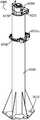
- Embodiment 1is a schematic overall structural view of a load-bearing column provided by Embodiment 1 of the present invention.
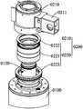
- FIG. 2is a schematic exploded view of a rotating shaft portion of a load bearing column according to Embodiment 1 of the present invention
- Embodiment 3is a schematic overall structural view of a bearing portion of a load bearing column provided by Embodiment 1 of the present invention.
- FIG. 4is a schematic top plan view of a load-bearing portion of a load-bearing column according to Embodiment 1 of the present invention.
- FIG. 5is a schematic exploded view of a load-bearing portion of a load-bearing column according to Embodiment 1 of the present invention.
- FIG. 6is a partially enlarged schematic view showing a bearing portion of a load bearing column according to Embodiment 1 of the present invention.
- FIG. 7is a schematic structural view of a first rotating arm of a bearing portion of a load bearing column according to Embodiment 1 of the present invention.
- FIG. 8is a schematic view showing the axial measurement structure of the cantilever device according to Embodiment 1 of the present invention.
- 10000-cantilever device1000-bearing column, 0100-column body, 0110-bottom support, 0120-rotor support, 0200-shaft part, 0210-rotor seat, 0211-first joint, 0220-bearing, 0221 - Cylindrical roller bearing, 0222-first thrust bearing, 0223-second thrust bearing, 0300-bearing part, 0310-rotary frame, 0311-bearing base, 0311a-second connecting part, 0311b-first linear motion Department, 0311c-second linear motion part, 0311d-locking part, 0311e-hinging shaft, 0132-first rotating arm, 0312a-first support plate, 0312b-second support plate, 0312c-support column, 0312d-end Fixed part, 0313 - 2nd swivel arm, 0314 - elastic element, 0320 - first rolling part, 0330 - 2nd rolling part, 2000 - rotating folding arm, 2100 - first arm, 2200 - second arm.
- the load column 1000has a column body 0100 , a rotating shaft portion 0200 and a bearing portion 0300 , which can bear a rotating load during the rotation of the cantilever, overcome the impact caused by the torque variation of the cantilever, and ensure the rotation of the cantilever in the horizontal direction. smooth.
- the specific structure of each part of the carrying column 1000will be described one by one below.
- the column body 0100As a support base that carries the column 1000, the column body 0100 is arranged in the vertical direction.
- the column body 0100should have sufficient structural strength and rigidity, and can adopt various structural forms such as a tubular structure, a solid cylinder, and the like.
- the column body 0100can also take a variety of shapes, such as square columns, cylinders, hexagonal columns, and the like.
- the column body 0100has at least one cylindrical surface between the upper and lower ends, and the central axis of the cylindrical surface coincides with the central axis of the column body 0100, so that the bearing portion 0300 rotatably maintains rolling contact with the cylindrical surface.
- the column body 0100employs a circular tube structure.
- the lower end of the column body 0100has a bottom support portion 0110 configured to lock the column body 0100 to the ground so that the column body 0100 obtains reliable support from the ground.
- the bottom support portion 0110can take a variety of structural forms, such as a disc shape, a hexagonal disc shape or other shapes, and corresponding ribs are provided to ensure structural strength.
- the connection of the bottom support portion 0110 to the groundcan also take various forms, such as screwing, welding, and the like.
- the upper end of the column main body 0100has a rotating shaft support portion 0120, and is disposed to be mounted with the rotating shaft portion 0200.
- the rotation shaft support portion 0120 and the rotation shaft portion 0200have a relative rotational motion to provide a rotation base of the rotation shaft portion 0200. More generally, the shaft support portion 0120 and the shaft portion 0200 are coupled by a shaft hole.
- the rotating shaft portion 0200is rotatably held by the rotating shaft support portion 0120, and the rotating shaft portion of the rotating shaft portion 0200 is parallel to the central axis of the column main body 0100.
- the rotating shaft portion 0200has a first connecting portion 0211 that is fixedly connected to the cantilever.
- the first connecting portion 0211can adopt various structures, such as a connecting hole, a connecting boss, a connecting plate, etc., and can be connected and fixed by means of screw connection, riveting, welding, or the like.
- the shaft portion 0200is rotatable on the column body 0100 under the control of the cantilever.
- the rotating shaft portion 0200has a rotating shaft seat 0210.
- the rotating shaft seat 0210is rotatably held by the rotating shaft supporting portion 0120, and a bearing portion 0220 is disposed between the rotating shaft seat 0210 and the rotating shaft supporting portion 0120.
- the shaft housing 0210has a rotary mating hole that is sleeved on a shaft support portion 0120 having a shaft form to form a rotatable shaft hole mating relationship.
- the bearing portion 0220functions as a bearing and is configured to withstand the load during the rotation process. Specifically, the inner ring of the bearing portion 0220 is sleeved with the rotating shaft support portion 0120, and the outer ring of the bearing portion 0220 is sleeved with the rotating shaft portion 0200 to provide a bearing function.
- the bearing portion 0220can take a variety of bearing forms to withstand axial and radial loads.
- the bearing portion 0220has a cylindrical roller bearing 0221 and a thrust bearing which are stacked in the axial direction of the rotating shaft seat 0210.
- the cylindrical roller bearing 0221 and the thrust bearingare stacked from top to bottom in the vertical direction.
- the rotating shaftis mainly carried by a double row tapered roller bearing or a crossed roller bearing.
- the roller bearingis an integrated bearing, which needs to carry both radial and axial loads.
- the rolleris wedged under the action of gravity to increase the motion resistance. The user needs to input a large rotating operation force to rotate.
- the cylindrical roller bearing 0221is configured to withstand radial load
- the thrust bearingis configured to withstand the axial load
- the separate load bearingavoids the roller wedge problem existing in the integrated bearing, thereby reducing the rotational operating force and improving the operation. effectiveness.
- the cylindrical roller bearing 0221is preferably a four-row cylindrical roller bearing including a first thrust bearing 0222 and a second thrust bearing 0223 disposed at both ends of the cylindrical roller bearing 0221.
- the bearing portion 0300is configured to be rotatably held on the column body 0100, and is subjected to the load and torque applied to the column body 0100 during the cantilever rotation process, and the pitch angle of the cantilever under the load is drifted.
- the compensationensures that the cantilever is always level, avoiding movement obstruction of the column body 0100 and the shaft portion 0200, reducing the horizontal operation rate that the user needs to apply, and improving the operation efficiency.
- the carrier portion 0300includes a rotating frame 0310.
- the rotating frame 0310can be held on the column body 0100 in synchronization with the rotating shaft portion 0200.
- the rotating frame 0310has a second connecting portion 0311a that is fixedly connected to the cantilever.
- the rotating frame 0310 and the rotating shaft portion 0200are fixedly connected via the cantilever, and have an integral rotational motion characteristic.
- the rotating frame 0310is disposed between the bottom support portion 0110 and the rotating shaft support portion 0120.
- the second connecting portion 0311acan adopt various structures, such as a connecting hole, a connecting boss, a connecting plate, etc., and can be connected and fixed by screwing, riveting, welding, or the like.
- the rotating frame 0310is provided with at least a pair of first rolling portions 0320 and at least one second rolling portion 0330 configured to provide a rolling load with rolling contact.
- the first rolling portions 0320 of the same pairare symmetrically distributed on both sides of the second connecting portion 0311a along the rotation direction of the rotating frame 0310.
- at least one second rolling portionis provided in a space away from the second connecting portion 0311a. 0330.
- first rolling portion 0320 and the second rolling portion 0330are respectively rotatably held on the rotating frame 0310 and in rolling contact with the column body 0100, and the rotating axis of the first rolling portion 0320 and the second rolling portion 0330 and the column body
- the center axis of 0100is parallel.
- the vertical line between the central axis of the first rolling portion 0320 and the central axis of the rotating frame 0310is a vertical positioning line, and the angle between the vertical positioning lines of the symmetric first rolling portion 0320 Not less than 30° and not more than 160°.
- the pair of first rolling portions 0320are symmetrically distributed with respect to the second connecting portion 0311a, and the pair of vertical positioning lines have the aforementioned included angle range.
- the first pair of first rolling portions 0320are always in the effective bearing range, fully function from both directions and the action is always kept stable and uniform, overcoming the problem caused by the torque variation of the cantilever.
- the angle between the vertical positioning lines of the symmetric first rolling portion 0320is not less than 80° and not more than 100°, and the bearing is more desirable.
- the first rolling portion 0320 and the second rolling portion 0330respectively comprise one of a rolling bearing or a rolling body.
- the first rolling portion 0320 and the second rolling portion 0330can each be a rolling bearing or a rolling body, that is, the same as a rolling bearing, both of which are rolling elements, one being a rolling bearing and the other rolling element.
- the outer ring of the rolling bearing or the outer surface of the rolling bodyis kept in contact with the column body 0100.
- Rolling bearingsinclude many types, and the rolling elements also include rollers, balls, and the like.
- the first rolling portion 0320 and the second rolling portion 0330may be of a structural type such as a scroll wheel.
- the second rolling portion 0330is evenly distributed between the outermost pair of first rolling portions 0320 and has a range of one to a plurality of numbers. Accordingly, the number of the first rolling portions 0320 is an even number and is symmetrically distributed in pairs. Further preferably, the first rolling portion 0320 and the second rolling portion 0330 adopt the same implementation manner, that is, the rolling bearing or the rolling body having the same structural size is used at the same time, so that the structure is more balanced.
- the rotating frame 0310can be of a unitary structure or an adjustable structure. Referring to FIG. 3 and FIG. 5 together, preferably, the rotating frame 0310 has a carrying base 0311, and the middle of the carrying base 0311 has a second connecting portion 0311a.
- the first rotating arm 0312 and the second rotating arm 0313are respectively hinged at two ends of the carrying base 0311. The one end of the first rotating arm 0312 away from the carrying base 0311 is separated from the end of the carrying base 0311 by the elastic element 0314 and the second rotating arm 0313. connection.
- the elastic member 0314includes various types of springs, elastic deformation pieces, and the like, and is configured to apply an elastic connection force between the first rotating arm 0312 and the second rotating arm 0313.
- the carrier base 0311, the first rotating arm 0312, the elastic element 0314 and the second rotating arm 0313are sequentially connected to form an annular structure, and the first rolling portion 0320 and the second rolling portion 0330 are distributed in the ring structure as described above. on.
- the position where the first rolling portion 0320 and the second rolling portion 0330 are actually locateddepends on the angular arrangement of the first rolling portion 0320 and the second rolling portion 0330, and the carrying base 0311, the first rotating arm 0312, and the second rotation.
- the two ends of the bearing base 0311are respectively disposed with a first linear motion portion 0311b and a second linear motion portion 0311c arranged in parallel, and the first rotating arm 0312 can be linearly moved to the first straight
- the second rotating arm 0313is linearly movable on the second linear motion portion 0311c, and the linear motion direction of the first rotating arm 0312 and the second rotating arm 0313 is along the symmetry plane of the second connecting portion 0311a. The intersection of the horizontal plane extends.
- the first linear motion portion 0311b and the second linear motion portion 0311cmay adopt a structure such as a groove body, a boss, and a slide rail, and provide a linear motion degree of the first rotating arm 0312 and the second rotating arm 0313.
- the symmetry plane of the second connecting portion 0311aextends in the vertical direction, and the first rotating arm 0312 and the second rotating arm 0313 can adjust the relative position of the second connecting portion 0312 and the second rotating arm 0313 in a linear motion to realize the first rolling portion 0320 and the second rolling portion.
- the position of 0330 and the column body 0100is adjusted to provide a more ideal bearing effect.
- the first linear motion portion 0311b and the second linear motion portion 0311crespectively have a locking portion 0311d, and the locking portion 0311d is respectively configured to limit linear motion of the first rotating arm 0312 and the second rotating arm 0313.
- the locking portions 0311drespectively act to lock the first rotating arm 0312 and the second rotating arm 0313 so that the latter two remain stationary.
- the locking portion 0311dcan use a connecting member such as a threaded fastener or a pin to lock the first rotating arm 0312 and the second rotating arm 0313.
- the first linear motion portion 0311b and the second linear motion portion 0311care respectively provided with threaded holes
- the locking portion 0311dis a bolt disposed in the threaded hole, and the bolt is spirally rotated to be tightly attached to the first A rotating arm 0312 or a second rotating arm 0313 causes the first rotating arm 0312 or the second rotating arm 0313 to be locked to the carrier base 0311.
- the first rotating arm 0312 and the second rotating arm 0313are symmetrically distributed on both ends of the bearing base 0311, and the bearing base 0311 and the second connecting portion 0311a both have a symmetrical structure, and the symmetric surface and the bearing of the second connecting portion 0311a
- the symmetry planes of the pedestal 0311coincide.
- the rotating frame 0310has a symmetric distribution structure whose symmetry plane coincides with the symmetry plane of the second connecting portion 0311a, and the pair of first rolling portions 0320 are uniformly symmetrical when carried.
- the first rotating arm 0312 and the second rotating arm 0313may take the same or different structural forms.
- the first rotating arm 0312 and the second rotating arm 0313are independent portions of the same symmetrical structure on both sides of the symmetry plane thereof, and have a similar structure.
- the first rotating arm 0312has a first supporting plate 0312a and a second supporting plate 0312b.
- the first supporting plate 0312a and the second supporting plate 0312bare connected and fixed by a support post 0312c.
- the first support plate 0312a and the second support plate 0312bhave a fan-shaped ring shape, respectively.
- the end of the first rotating arm 0312 away from the second connecting portion 0311afurther has an end fixing portion 0312d, and the end fixing portion 0312d is disposed to be fixedly coupled to one end of the elastic member 0314.
- the first support plate 0312a and the second support plate 0312bare respectively connected at both ends of the end fixing portion 0312d to further strengthen the structural strength.
- a first rolling portion 0320is disposed at a joint of the first rotating arm 0312 and the carrying base 0311, and a second rolling portion 0330 is disposed at an end of the first rotating arm 0312 away from the carrying base 0311, and the first rolling portion 0320 is The second rolling portion 0330 is rotatably held by the first rotating arm 0312.
- the distribution of the first rolling portion 0320 and the second rolling portion 0330 on the second rotating arm 0313coincides with the first rotating arm 0312 to form a symmetrical structure.
- the first rotating arm 0312 and the second rotating arm 0313are respectively hinged to both ends of the carrier base 0311.
- the first rotating arm 0312 and the second rotating arm 0313have the ability to rotate about the hinge axis 0311e of each of the carrier bases 0311, so that the first two have a certain degree of rotation adjustment capability.
- the elastic element 0314always applies a connection load to the first rotating arm 0312 and the second rotating arm 0313 to keep the latter two tightly connected, and the first rolling portion 0320 and the second rolling portion 0330 are always in rolling contact with the column body 0100. .
- the first rolling portion 0320is rotatably held on the first rotating arm 0312, the second rotating arm 0313, and the hinge shaft 0311e of the carrier base 0311, respectively. Further preferably, the second rolling portion 0330 is rotatably held on the support post 0312c.
- a cantilever device 10000is described herein, including the load-bearing column 1000 and a rotating folding arm 2000 rotatably held on the load-bearing column 1000, configured to provide a desired horizontal operating force and operation. Efficient lifting device.
- the rotating arm 2000includes a first arm 2100 and a second arm 2200.
- the first arm 2100is fixedly connected to the first connecting portion 0211 and the second connecting portion 0311a, respectively.
- the first arm 2100is away from the end of the supporting column 1000 and the second portion.
- the arm 2200is hinged.
- first arm 2100rotates integrally with the rotating shaft portion 0200 and the rotating frame 0310 to provide overall rotation of the rotating folding arm 2000.
- the second arm 2200is rotatable about the hinge of the first arm 2100 and the second arm 2200 to extend or fold the first arm 2100 and the second arm 2200.
- the rotating knuckle arm 2000has two rotational movements, namely the overall rotation of the rotating knuckle arm 2000 and the rotational overhang of the second arm 2200.
- the blocking torquehas a very significant change.
- the force armis rapidly increased, and the rotating folding arm 2000 has a significant sag under the varying bending moment. Due to the load compensation of the load column 1000, the motion interference and drift effects are effectively reduced, and the horizontal operating force is reduced to a desired range.
- the useronly needs to input a horizontal operating force as low as a few Newtons to drive the rotating folding arm 2000 to rotate, which greatly improves the operating efficiency.
Landscapes
- Engineering & Computer Science (AREA)
- Mechanical Engineering (AREA)
- Road Signs Or Road Markings (AREA)
- Rolling Contact Bearings (AREA)
- Pivots And Pivotal Connections (AREA)
Abstract
Description
Translated fromChinese相关申请的交叉引用Cross-reference to related applications
本申请要求于2017年09月01日提交中国专利局的申请号为CN201710777588.5、名称为“承载立柱与悬臂装置”的中国专利申请的优先权,其全部内容通过引用结合在本申请中。The present application claims priority to Chinese Patent Application No. CN201710777588.5, entitled "Carrying Columns and Cantilever Devices", filed on Sep. 1, 2017, the entire contents of which is incorporated herein by reference.
本发明属于起重机械技术领域,具体地来说,是一种承载立柱与悬臂装置。The invention belongs to the technical field of lifting machinery, in particular to a supporting column and a cantilever device.
立柱是一种起重机械领域的常见部件,其铅垂地竖立于地面或机架上,对连接于立柱上的其他部件提供支撑。一般地,立柱需要具有足够的刚性,以保证充足的承载能力。Columns are a common component in the field of lifting machinery that is vertically erected on the ground or frame to support other components attached to the column. In general, the columns need to be sufficiently rigid to ensure adequate load carrying capacity.
在受支撑部件具有旋转运动的场合,例如自立式悬臂吊中,立柱需要同时承受载荷力与转矩作用。一般地,可旋转的受支撑部件为悬臂,在水平操作力的推动下绕设于立柱的旋转轴旋转。其中,水平操作力是考察操作舒适性与效率的重要指标。Where the supported member has a rotational motion, such as a self-supporting cantilever crane, the column needs to be subjected to both load and torque. Generally, the rotatable supported member is a cantilever that is rotated about a rotating shaft provided on the column by a horizontal operating force. Among them, the horizontal operating force is an important indicator to examine the comfort and efficiency of the operation.
水平操作力配置成克服悬臂旋转的阻力与阻碍力矩,一般地,阻力包括悬臂与负载的重力,阻碍力矩包括重力引起的弯扭矩。特别是在悬臂采用折臂结构的情况下,阻碍力矩还包括折臂旋转外伸产生的弯扭矩。由于旋转轴设于立柱上并与悬臂连接,旋转轴在立柱上的结构布置对于旋转阻力与阻碍力矩具有重要影响。The horizontal operating force is configured to overcome the resistance of the cantilever rotation and the blocking torque. Generally, the resistance includes the weight of the cantilever and the load, and the blocking torque includes the bending torque caused by gravity. In particular, in the case where the cantilever has a folding arm structure, the blocking torque also includes a bending torque generated by the rotation of the folding arm. Since the rotating shaft is disposed on the column and connected to the cantilever, the structural arrangement of the rotating shaft on the column has an important influence on the rotational resistance and the blocking torque.
在传统的立柱结构中,由于结构所限,对于旋转轴的阻碍作用偏大,往往需要很大的水平操作力,操作效率低下。尤其在负载的重力作用下,悬臂还会受压下垂而发生漂移,加剧立柱对于旋转轴的运动阻碍作用,使需要的水平操作力进一步增加。In the conventional column structure, due to the limitation of the structure, the obstruction effect on the rotating shaft is too large, and a large horizontal operating force is often required, and the operation efficiency is low. Especially under the gravity of the load, the cantilever will also sag and drift, which will aggravate the movement of the column to the movement of the rotating shaft, and further increase the required horizontal operating force.
发明内容Summary of the invention
为了克服现有技术的不足,本发明提供了一种承载立柱与悬臂装置,可降低悬臂旋转过程中的水平操作力,提高悬臂的操作效率并减轻操作者的负担。In order to overcome the deficiencies of the prior art, the present invention provides a bearing column and a cantilever device, which can reduce the horizontal operating force during the rotation of the cantilever, improve the operating efficiency of the cantilever and reduce the burden on the operator.
本发明的目的通过以下技术方案来实现:The object of the invention is achieved by the following technical solutions:
一种承载立柱,具有立柱本体、转轴部与承载部:A bearing column has a column body, a rotating shaft portion and a bearing portion:
所述立柱本体两端分别具有底部支撑部与转轴支撑部,所述底部支撑部配置成与地面连接,所述转轴部可旋转地保持于所述转轴支撑部,所述转轴部的旋转轴与所述立柱本体的中心轴平行,所述转轴部具有配置成与悬臂固定连接的第一连接部;Each of the two ends of the column body has a bottom support portion and a rotation shaft support portion, the bottom support portion is disposed to be connected to the ground, the rotation shaft portion is rotatably held by the rotation shaft support portion, and the rotation axis of the rotation shaft portion is The central axis of the column body is parallel, and the rotating shaft portion has a first connecting portion configured to be fixedly coupled to the cantilever;
所述承载部包括旋转架,所述旋转架可与所述转轴部共轴同步旋转地保持于所述立柱本体上,所述旋转架具有配置成与所述悬臂固定连接的第二连接部;The carrying portion includes a rotating frame, and the rotating frame is rotatably held coaxially with the rotating shaft portion on the column body, and the rotating frame has a second connecting portion configured to be fixedly coupled to the cantilever;
所述第二连接部沿所述旋转架的旋转方向两侧对称地各设有至少一个第一滚动部,成对对称分布的所述第一滚动部中,处于最外侧的一对所述第一滚动部之间在其远离所述第二连接部的一侧设有至少一个第二滚动部,所述第一滚动部和所述第二滚动部分别可旋转地保持于所述旋转架上并与所述立柱本体保持滚动接触,且所述第一滚动部和所述第二滚动部的旋转轴与所述立柱本体的中心轴平行。The second connecting portion is provided with at least one first rolling portion symmetrically on both sides of the rotating frame in the rotating direction, and the pair of the first rolling portions in the pair of the first rolling portions symmetrically distributed At least one second rolling portion is disposed between a rolling portion on a side thereof away from the second connecting portion, and the first rolling portion and the second rolling portion are rotatably held on the rotating frame, respectively And maintaining rolling contact with the column body, and rotation axes of the first rolling portion and the second rolling portion are parallel to a central axis of the column body.
作为上述技术方案的改进,所述旋转架具有承载基座及分别铰接于所述承载基座两端的第一旋转臂与第二旋转臂,所述承载基座中部具有所述第二连接部,所述第一旋转臂远离所述承载基座的一端通过弹性元件与所述第二旋转臂远离所述承载基座的一端连接。As a modification of the above technical solution, the rotating frame has a carrying base and a first rotating arm and a second rotating arm respectively hinged at two ends of the carrying base, and the second connecting portion is formed in a middle portion of the carrying base. An end of the first rotating arm away from the carrying base is connected to an end of the second rotating arm away from the carrying base by an elastic element.
作为上述技术方案的进一步改进,所述第一旋转臂与所述第二旋转臂对称地分布于所述承载基座两端,所述承载基座与所述第二连接部均具有对称结构,所述第二连接部的对称面与所述承载基座的对称面重合。As a further improvement of the above technical solution, the first rotating arm and the second rotating arm are symmetrically distributed at two ends of the carrying base, and the carrying base and the second connecting portion both have a symmetrical structure. The plane of symmetry of the second connecting portion coincides with the plane of symmetry of the bearing base.
作为上述技术方案的进一步改进,所述承载基座两端分别设有平行布置的第一直线运动部与第二直线运动部,所述第一旋转臂可直线运动地保持于所述第一直线运动部上,所述第二旋转臂可直线运动地保持于所述第二直线运动部上,所述第一旋转臂与所述第二旋转臂的直线运动方向沿所述第二连接部的对称面与水平面的交线延伸方向。As a further improvement of the above technical solution, the two ends of the carrying base are respectively provided with a first linear moving portion and a second linear moving portion arranged in parallel, and the first rotating arm is linearly movable to the first The second rotating arm is linearly movable on the second linear motion portion, and the linear motion direction of the first rotating arm and the second rotating arm is along the second connection The direction of intersection of the symmetry plane of the part and the horizontal plane.
作为上述技术方案的进一步改进,所述第一直线运动部与所述第二直线运动部分别具有锁止部,所述锁止部分别配置成限制所述第一旋转臂与所述第二旋转臂的直线运动。As a further improvement of the above technical solution, the first linear motion portion and the second linear motion portion respectively have locking portions, and the locking portions are respectively configured to limit the first rotating arm and the second The linear motion of the rotating arm.
作为上述技术方案的进一步改进,所述第一滚动部的中心轴与所述旋转架的中心轴之间的垂直连线为垂直定位线,对称的所述第一滚动部的所述垂直定位线之间的夹角不小于30°且不大于160°。As a further improvement of the above technical solution, the vertical line between the central axis of the first rolling portion and the central axis of the rotating frame is a vertical positioning line, and the vertical positioning line of the first rolling portion is symmetric The angle between them is not less than 30° and not more than 160°.
作为上述技术方案的进一步改进,所述转轴部具有转轴座,所述转轴座可旋转地保持于所述转轴支撑部,所述转轴座与所述转轴支撑部之间设有轴承部。As a further improvement of the above technical solution, the rotating shaft portion has a rotating shaft seat, the rotating shaft seat is rotatably held by the rotating shaft supporting portion, and a bearing portion is disposed between the rotating shaft seat and the rotating shaft supporting portion.
作为上述技术方案的进一步改进,所述轴承部具有沿所述转轴座的轴向层叠布置的圆柱滚子轴承与推力轴承。As a further improvement of the above technical solution, the bearing portion has a cylindrical roller bearing and a thrust bearing which are stacked in the axial direction of the rotating shaft seat.
作为上述技术方案的进一步改进,所述第二滚动部沿所述旋转架的旋转圆周均匀分布于最外侧的一对对称分布的所述第一滚动部之间。As a further improvement of the above technical solution, the second rolling portion is evenly distributed between the outermost pair of symmetrically distributed first rolling portions along the rotation circumference of the rotating frame.
一种悬臂装置,包括以上所述的承载立柱与可旋转地保持于所述承载立柱上的旋转折臂:A cantilever device comprising the above-described carrying column and a rotating folding arm rotatably held on the carrying column:
所述旋转折臂包括第一臂与第二臂,所述第一臂分别与所述第一连接部和所述第二连接部固定连接,所述第一臂远离所述承载立柱的一端与所述第二臂铰接。The rotating folding arm includes a first arm and a second arm, wherein the first arm is fixedly connected to the first connecting portion and the second connecting portion respectively, and the first arm is away from an end of the supporting column and The second arm is hinged.
本发明的有益效果是:The beneficial effects of the invention are:
于立柱本体上分别设置转轴部与承载部,转轴部与承载部分别与悬臂固定连接而可旋转地保持于立柱本体上,承载部具有至少一对对称分布的第一滚动部与至少一个第二滚动部,第一滚动部与第二滚动部形成环形支撑,对悬臂的俯仰角进行自动补偿,防止悬臂发生漂移,减少立柱对于转轴部的运动阻碍,降低水平操作力,提高操作效率。A rotating shaft portion and a carrying portion are respectively disposed on the main body of the column, and the rotating shaft portion and the carrying portion are respectively fixedly coupled to the cantilever and rotatably held on the column body, and the carrying portion has at least one pair of symmetrically distributed first rolling portions and at least one second The rolling portion, the first rolling portion and the second rolling portion form an annular support, automatically compensates the pitch angle of the cantilever, prevents the cantilever from drifting, reduces the movement hindrance of the column to the rotating shaft portion, reduces the horizontal operating force, and improves the operating efficiency.
为使本发明的上述目的、特征和优点能更明显易懂,下文特举较佳实施例,并配合所附附图,作详细说明如下。The above described objects, features, and advantages of the invention will be apparent from the description and appended claims appended claims
为了更清楚地说明本发明实施例的技术方案,下面将对实施例中所需要使用的附图作简单地介绍,应当理解,以下附图仅示出了本发明的某些实施例,因此不应被看作是对范围的限定,对于本领域普通技术人员来讲,在不付出创造性劳动的前提下,还可以根据这些附图获得其他相关的附图。In order to more clearly illustrate the technical solutions of the embodiments of the present invention, the drawings used in the embodiments will be briefly described below. It should be understood that the following drawings show only certain embodiments of the present invention, and therefore It should be seen as a limitation on the scope, and those skilled in the art can obtain other related drawings according to these drawings without any creative work.
图1是本发明实施例1提供的承载立柱的整体结构示意图;1 is a schematic overall structural view of a load-bearing column provided by Embodiment 1 of the present invention;
图2是本发明实施例1提供的承载立柱的转轴部的分解结构示意图;2 is a schematic exploded view of a rotating shaft portion of a load bearing column according to Embodiment 1 of the present invention;
图3是本发明实施例1提供的承载立柱的承载部的整体结构示意图;3 is a schematic overall structural view of a bearing portion of a load bearing column provided by Embodiment 1 of the present invention;
图4是本发明实施例1提供的承载立柱的承载部的俯视结构示意图;4 is a schematic top plan view of a load-bearing portion of a load-bearing column according to Embodiment 1 of the present invention;
图5是本发明实施例1提供的承载立柱的承载部的分解结构示意图;5 is a schematic exploded view of a load-bearing portion of a load-bearing column according to Embodiment 1 of the present invention;
图6是本发明实施例1提供的承载立柱的承载部的局部放大示意图;6 is a partially enlarged schematic view showing a bearing portion of a load bearing column according to Embodiment 1 of the present invention;
图7是本发明实施例1提供的承载立柱的承载部的第一旋转臂的结构示意图;7 is a schematic structural view of a first rotating arm of a bearing portion of a load bearing column according to Embodiment 1 of the present invention;
图8是本发明实施例1提供的悬臂装置的轴测结构示意图。8 is a schematic view showing the axial measurement structure of the cantilever device according to Embodiment 1 of the present invention.
主要元件符号说明:The main component symbol description:
10000-悬臂装置,1000-承载立柱,0100-立柱本体,0110-底部支撑部,0120-转轴支撑部,0200-转轴部,0210-转轴座,0211-第一连接部,0220-轴承部,0221-圆柱滚子轴承,0222-第一推力轴承,0223-第二推力轴承,0300-承载部,0310-旋转架,0311-承载基座,0311a-第二连接部,0311b-第一直线运动部,0311c-第二直线运动部,0311d-锁止部,0311e-铰接轴,0312-第一旋转臂,0312a-第一支板,0312b-第二支板,0312c-支撑柱,0312d-端部固定部,0313-第二旋转臂,0314-弹性元件,0320-第一滚动部,0330-第二滚动部,2000-旋转折臂,2100-第一臂,2200-第二臂。10000-cantilever device, 1000-bearing column, 0100-column body, 0110-bottom support, 0120-rotor support, 0200-shaft part, 0210-rotor seat, 0211-first joint, 0220-bearing, 0221 - Cylindrical roller bearing, 0222-first thrust bearing, 0223-second thrust bearing, 0300-bearing part, 0310-rotary frame, 0311-bearing base, 0311a-second connecting part, 0311b-first linear motion Department, 0311c-second linear motion part, 0311d-locking part, 0311e-hinging shaft, 0132-first rotating arm, 0312a-first support plate, 0312b-second support plate, 0312c-support column, 0312d-end Fixed part, 0313 - 2nd swivel arm, 0314 - elastic element, 0320 - first rolling part, 0330 - 2nd rolling part, 2000 - rotating folding arm, 2100 - first arm, 2200 - second arm.
为了便于理解本发明,下面将参照相关附图对承载立柱与悬臂装置进行更全面的描述。 附图中给出了承载立柱与悬臂装置的优选实施例。但是,承载立柱与悬臂装置可以通过许多不同的形式来实现,并不限于本文所描述的实施例。相反地,提供这些实施例的目的是使对承载立柱与悬臂装置的公开内容更加透彻全面。In order to facilitate the understanding of the present invention, a more complete description of the load column and the boom device will be made below with reference to the related drawings. A preferred embodiment of the carrying column and cantilever arrangement is given in the drawings. However, the load column and cantilever arrangement can be implemented in many different forms and is not limited to the embodiments described herein. Rather, the purpose of providing these embodiments is to make the disclosure of the load column and cantilever device more thorough and comprehensive.
需要说明的是,当元件被称为“固定于”另一个元件,它可以直接在另一个元件上或者也可以存在居中的元件。当一个元件被认为是“连接”另一个元件,它可以是直接连接到另一个元件或者可能同时存在居中元件。相反,当元件被称作“直接在”另一元件“上”时,不存在中间元件。本文所使用的术语“垂直的”、“水平的”、“左”、“右”以及类似的表述只是为了说明的目的。It should be noted that when an element is referred to as being "fixed" to another element, it can be directly on the other element or the element can be present. When an element is considered to be "connected" to another element, it can be directly connected to the other element or. In contrast, when an element is referred to as being "directly on" another element, there is no intermediate element. The terms "vertical," "horizontal," "left," "right," and the like, as used herein, are for illustrative purposes only.
除非另有定义,本文所使用的所有的技术和科学术语与属于本发明的技术领域的技术人员通常理解的含义相同。本文中在承载立柱与悬臂装置的说明书中所使用的术语只是为了描述具体的实施例的目的,不是旨在限制本发明。本文所使用的术语“及/或”包括一个或多个相关的所列项目的任意的和所有的组合。All technical and scientific terms used herein have the same meaning as commonly understood by one of ordinary skill in the art to which this invention belongs, unless otherwise defined. The terminology used herein to carry the column and the cantilever device is for the purpose of describing the specific embodiments and is not intended to limit the invention. The term "and/or" used herein includes any and all combinations of one or more of the associated listed items.
实施例1Example 1
请参阅图1,承载立柱1000具有立柱本体0100、转轴部0200与承载部0300,可在悬臂旋转过程中承受旋转载荷,克服因悬臂的转矩变化带来的冲击,保证悬臂于水平方向的旋转平稳。以下逐一介绍承载立柱1000各部分的具体结构。Referring to FIG. 1 , the
作为承载立柱1000的支撑基体,立柱本体0100沿铅垂方向布置。立柱本体0100应具有足够的结构强度与刚度,并可采用多种结构形式,如管状结构、实心柱体等。立柱本体0100亦可采用多种形状,如方柱、圆柱、六角柱体等。立柱本体0100于上下端之间至少具有一圆柱面,圆柱面的中心轴与立柱本体0100的中心轴重合,以便承载部0300可旋转地与圆柱面保持滚动接触。在一个示范性的实施例中,立柱本体0100采用圆管结构。As a support base that carries the
立柱本体0100下端具有底部支撑部0110,配置成将立柱本体0100锁紧于地面,使立柱本体0100获得源自地面的可靠支撑。底部支撑部0110可采用多种结构形式,如圆盘形、六角盘形或其他形状,并设置相应的加强筋以保证结构强度。底部支撑部0110与地面的连接亦可采用多种形式,如螺纹连接、焊接等。The lower end of the
请结合参阅图1~2,立柱本体0100上端具有转轴支撑部0120,配置成安装转轴部0200。转轴支撑部0120与转轴部0200具有相对旋转运动,以提供转轴部0200的旋转基础。较常见地,转轴支撑部0120与转轴部0200之间以轴孔配合连接。Referring to FIGS. 1 and 2, the upper end of the column
转轴部0200可旋转地保持于转轴支撑部0120,转轴部0200的旋转轴与立柱本体0100的中心轴平行,转轴部0200具有配置成与悬臂固定连接的第一连接部0211。其中,第一连接部0211可采用多种结构,如连接孔、连接凸台、连接板等,并可通过螺纹连接、铆接、焊接等形式连接固定。在悬臂带动下,转轴部0200可于立柱本体0100上旋转。The
优选地,转轴部0200具有转轴座0210,转轴座0210可旋转地保持于转轴支撑部0120,转轴座0210与转轴支撑部0120之间设有轴承部0220。在一个示范性的实施例中,转轴座0210具有旋转配合孔,套接于具有轴形式的转轴支撑部0120上,形成可旋转的轴孔配合关系。Preferably, the
其中,轴承部0220起轴承作用,配置成承受转动过程的载荷。具体地,轴承部0220的内圈与转轴支撑部0120套接,轴承部0220的外圈与转轴部0200套接,而提供承载功能。轴承部0220可采用多种轴承形式,以承受轴向与径向载荷。Among them, the bearing
优选地,轴承部0220具有沿转轴座0210的轴向层叠布置的圆柱滚子轴承0221与推力轴承。具体地,圆柱滚子轴承0221与推力轴承沿铅垂方向自上而下层叠。在传统的立柱结构中,主要采用双列圆锥滚子轴承或交叉滚子轴承对转动轴进行承载。而滚子轴承属于一体式承载,需要同时承载径向与轴向载荷,滚子在重力作用下楔紧而增大运动阻力,用户需要输入较大的转动操作力才能旋转。在本实施例中,圆柱滚子轴承0221配置成承受径向载荷,推力轴承配置成承受轴向载荷,以分离式承载规避一体式承载存在的滚子楔紧问题,降低转动操作力而提高操作效率。在一个示范性的实施例中,圆柱滚子轴承0221优选为四列圆柱滚子轴承,推力轴承包括设于圆柱滚子轴承0221两端的第一推力轴承0222与第二推力轴承0223。Preferably, the bearing
请结合参阅图1及图3,承载部0300配置成旋转地保持于立柱本体0100上,承受悬臂转动过程对立柱本体0100施加的载荷与转矩,并对悬臂在负载作用下漂移的俯仰角进行补偿,使悬臂始终保持水平,避免立柱本体0100与转轴部0200发生运动阻碍,降低用户需要施加的水平操作率,提高操作效率。Referring to FIG. 1 and FIG. 3, the bearing
其中,承载部0300包括旋转架0310,旋转架0310可与转轴部0200共轴同步旋转地保持于立柱本体0100上,且旋转架0310具有配置成与悬臂固定连接的第二连接部0311a。换言之,旋转架0310与转轴部0200经悬臂而实现固定连接,具有一体的旋转运动特性。一般地,旋转架0310设于底部支撑部0110与转轴支撑部0120之间。其中,第二连接部0311a可采用多种结构,如连接孔、连接凸台、连接板等,并可通过螺纹连接、铆接、焊接等形式连接固定。The
旋转架0310上并设有至少一对第一滚动部0320与至少一个第二滚动部0330,配置成提供滚动承载,具有滚动接触。其中,同对的第一滚动部0320沿旋转架0310的旋转方向对称地分布于第二连接部0311a的两侧。成对对称分布的第一滚动部0320中,处于最外侧的一对第一滚动部0320之间,在其远离所述第二连接部0311a的一侧空间内,设有至少一个第二滚动部0330。同时,第一滚动部0320、第二滚动部0330分别可旋转地保持于旋转架0310上并与立柱本体0100保持滚动接触,且第一滚动部0320、第二滚动部0330的旋 转轴与立柱本体0100的中心轴平行。The
请参阅图4,优选地,第一滚动部0320的中心轴与旋转架0310的中心轴之间的垂直连线为垂直定位线,对称的第一滚动部0320的垂直定位线之间的夹角不小于30°且不大于160°。换言之,同对的第一滚动部0320关于第二连接部0311a对称分布,且同对的垂直定位线之间具有前述夹角范围。当悬臂于水平面内旋转时,同对的第一滚动部0320始终处于有效的承载范围内,从两个方向充分作用且作用始终保持平稳均匀,克服悬臂的转矩变化带来的问题。进一步优选,对称的第一滚动部0320的垂直定位线之间的夹角不小于80°且不大于100°,承载更为理想。Referring to FIG. 4, preferably, the vertical line between the central axis of the
优选地,第一滚动部0320和第二滚动部0330分别包括滚动轴承或滚动体中的一种。换言之,第一滚动部0320与第二滚动部0330可分别为滚动轴承或滚动体,即二者同为滚动轴承、二者同为滚动体、一者为滚动轴承而另一者滚动体的实现方式。其中,滚动轴承的外圈或滚动体的外表面与立柱本体0100保持接触。滚动轴承包括多种类型,滚动体亦包括滚子、滚珠等形式。在另一个实施例中,第一滚动部0320和第二滚动部0330尚可采用滚轮等结构类型。Preferably, the
在一个示范性的实施例中,第二滚动部0330均匀分布于最外侧的一对第一滚动部0320之间,并具有一至复数个的数量范围。相应地,第一滚动部0320的数量为偶数个并成对对称分布。进一步优选,第一滚动部0320与第二滚动部0330采用相同的实现方式,即同时采用结构尺寸完全一致的滚动轴承或滚动体,使结构更为均衡。In an exemplary embodiment, the
旋转架0310可采用一体结构,亦可采用可调节结构。请结合参阅图3及图5,优选地,旋转架0310具有承载基座0311,承载基座0311中部具有第二连接部0311a。承载基座0311两端分别铰接有第一旋转臂0312与第二旋转臂0313,第一旋转臂0312远离承载基座0311的一端通过弹性元件0314与第二旋转臂0313远离承载基座0311的一端连接。其中,弹性元件0314包括各类弹簧、弹性变形片等,配置成在第一旋转臂0312与第二旋转臂0313之间施加弹性连接力。The
在此,承载基座0311、第一旋转臂0312、弹性元件0314与第二旋转臂0313依次连接而成环形结构,第一滚动部0320与第二滚动部0330如前所述地分布于环形结构上。其中,第一滚动部0320与第二滚动部0330实际所处的位置,取决于第一滚动部0320、第二滚动部0330的角度安排及承载基座0311、第一旋转臂0312、第二旋转臂0313三者各自相对于旋转架0310旋转轴的圆心角范围。Here, the
请结合参阅图6,优选地,承载基座0311两端分别设有平行布置的第一直线运动部0311b与第二直线运动部0311c,第一旋转臂0312可直线运动地保持于第一直线运动部0311b上,第二旋转臂0313可直线运动地保持于第二直线运动部0311c上,第一旋转臂0312 与第二旋转臂0313的直线运动方向沿第二连接部0311a的对称面与水平面的交线延伸方向。Referring to FIG. 6 , preferably, the two ends of the
其中,第一直线运动部0311b与第二直线运动部0311c可采用槽体、凸台、滑轨等结构形式,提供第一旋转臂0312与第二旋转臂0313的直线运动自由度。第二连接部0311a的对称面沿铅垂方向延伸,第一旋转臂0312与第二旋转臂0313可直线运动地调节自身与立柱本体0100的相对位置,实现第一滚动部0320、第二滚动部0330与立柱本体0100的位置调节,提供更为理想的承载效果。The first
优选地,第一直线运动部0311b与第二直线运动部0311c分别具有锁止部0311d,锁止部0311d分别配置成限制第一旋转臂0312与第二旋转臂0313的直线运动。换言之,当第一旋转臂0312、第二旋转臂0313调节到位后,锁止部0311d分别作用而锁紧第一旋转臂0312、第二旋转臂0313,使后二者保持静止。Preferably, the first
其中,锁止部0311d可采用螺纹紧固件、销等连接件,对第一旋转臂0312、第二旋转臂0313实施锁止限位。在一个示范性的实施例中,第一直线运动部0311b与第二直线运动部0311c分别设有螺纹孔,锁止部0311d为设于螺纹孔内的螺栓,螺栓螺旋旋转而顶紧于第一旋转臂0312或第二旋转臂0313,使第一旋转臂0312或第二旋转臂0313被锁紧于承载基座0311上。The locking
优选地,第一旋转臂0312与第二旋转臂0313对称地分布于承载基座0311两端,承载基座0311与第二连接部0311a均具有对称结构,第二连接部0311a的对称面与承载基座0311的对称面重合。换言之,旋转架0310具有对称分布结构,其对称面与第二连接部0311a的对称面重合,同对的第一滚动部0320承载时均匀对称。Preferably, the first
第一旋转臂0312与第二旋转臂0313可采用相同或相异的结构形式。在如前所述的对称结构的实施例中,第一旋转臂0312与第二旋转臂0313为同一对称结构在其对称面两侧的独立部分,具有相类的结构。The first
请结合参阅图5及图7,仅以第一旋转臂0312为例,在一个示范性的实施例中作简要介绍。第一旋转臂0312具有第一支板0312a与第二支板0312b,第一支板0312a与第二支板0312b之间通过支撑柱0312c相连而固定。较佳地,第一支板0312a与第二支板0312b分别具有扇形环形状。第一旋转臂0312远离第二连接部0311a的一端还具有端部固定部0312d,端部固定部0312d配置成与弹性元件0314的一端固定连接。同时,端部固定部0312d两端分别连接第一支板0312a与第二支板0312b,进一步加强结构强度。Referring to FIG. 5 and FIG. 7 together, only the first
进一步优选,第一旋转臂0312与承载基座0311的连接处设有第一滚动部0320,第一旋转臂0312远离承载基座0311的一端设有第二滚动部0330,第一滚动部0320与第二滚动部0330均可旋转地保持于第一旋转臂0312上。第二旋转臂0313上的第一滚动部0320、 第二滚动部0330的分布情况与第一旋转臂0312一致,形成对称结构。Further preferably, a
如前所述,第一旋转臂0312与第二旋转臂0313分别铰接于承载基座0311的两端。换言之,第一旋转臂0312与第二旋转臂0313具有绕各自与承载基座0311的铰接轴0311e旋转的能力,使前二者具有一定的旋转调节能力。同时,弹性元件0314始终对第一旋转臂0312、第二旋转臂0313施加连接载荷,使后二者保持紧密连接,第一滚动部0320与第二滚动部0330得以始终与立柱本体0100保持滚动接触。在一个示范性的实施例中,第一滚动部0320分别旋转地保持于第一旋转臂0312、第二旋转臂0313与承载基座0311的铰接轴0311e上。进一步优选,第二滚动部0330可旋转地保持于支撑柱0312c上。As described above, the first
请参阅图8,在此一并介绍一种悬臂装置10000,包括所述的承载立柱1000与可旋转地保持于承载立柱1000上的旋转折臂2000,配置成提供具有理想的水平操作力与操作效率的起重装置。Referring to FIG. 8, a
其中,旋转折臂2000包括第一臂2100与第二臂2200,第一臂2100分别与第一连接部0211、第二连接部0311a固定连接,第一臂2100远离承载立柱1000的一端与第二臂2200铰接。The
在此,第一臂2100与转轴部0200、旋转架0310一体旋转,提供旋转折臂2000的整体旋转。第二臂2200可绕第一臂2100与第二臂2200的铰接部旋转,使第一臂2100与第二臂2200伸展或折叠。Here, the
换言之,旋转折臂2000具有两种旋转运动,即旋转折臂2000的整体旋转与第二臂2200的旋转外伸。在旋转折臂2000的运动过程,阻碍力矩具有十分明显的变化。特别是第二臂2200的旋转外伸过程,作用力臂迅速增大,旋转折臂2000在变化弯矩下发生十分明显的下垂。由于承载立柱1000的承载补偿,有效地降低了运动干涉与漂移影响,使水平操作力降低到理想范围。用户仅需输入低至几牛顿的水平操作力,即可驱动旋转折臂2000旋转,使操作效率大为提高。In other words, the
在这里示出和描述的所有示例中,任何具体值应被解释为仅仅是示例性的,而不是作为限制,因此,示例性实施例的其他示例可以具有不同的值。In all of the examples shown and described herein, any specific values should be construed as merely exemplary, and not as a limitation, and thus, other examples of the exemplary embodiments may have different values.
应注意到:相似的标号和字母在下面的附图中表示类似项,因此,一旦某一项在一个附图中被定义,则在随后的附图中不需要对其进行进一步定义和解释。It should be noted that similar reference numerals and letters indicate similar items in the following figures. Therefore, once an item is defined in one figure, it is not necessary to further define and explain it in the subsequent figures.
以上所述实施例仅表达了本发明的几种实施方式,其描述较为具体和详细,但并不能因此而理解为对本发明范围的限制。应当指出的是,对于本领域的普通技术人员来说,在不脱离本发明构思的前提下,还可以做出若干变形和改进,这些都属于本发明的保护范围。因此,本发明的保护范围应以所附权利要求为准。The above-described embodiments are merely illustrative of several embodiments of the present invention, and are not to be construed as limiting the scope of the invention. It should be noted that a number of variations and modifications may be made by those skilled in the art without departing from the spirit and scope of the invention. Therefore, the scope of the invention should be determined by the appended claims.
Claims (10)
Translated fromChineseApplications Claiming Priority (2)
| Application Number | Priority Date | Filing Date | Title |
|---|---|---|---|
| CN201710777588.5ACN107324226B (en) | 2017-09-01 | 2017-09-01 | Carry column and cantilever arrangement |
| CN201710777588.5 | 2017-09-01 |
Publications (1)
| Publication Number | Publication Date |
|---|---|
| WO2019041997A1true WO2019041997A1 (en) | 2019-03-07 |
Family
ID=60204736
Family Applications (1)
| Application Number | Title | Priority Date | Filing Date |
|---|---|---|---|
| PCT/CN2018/093067CeasedWO2019041997A1 (en) | 2017-09-01 | 2018-06-27 | Carrying column and cantilever device |
Country Status (2)
| Country | Link |
|---|---|
| CN (1) | CN107324226B (en) |
| WO (1) | WO2019041997A1 (en) |
Cited By (1)
| Publication number | Priority date | Publication date | Assignee | Title |
|---|---|---|---|---|
| US11072517B2 (en)* | 2019-04-11 | 2021-07-27 | Kundel Industries, Inc. | Jib crane with tension frame and compression support |
Families Citing this family (2)
| Publication number | Priority date | Publication date | Assignee | Title |
|---|---|---|---|---|
| CN107324226B (en)* | 2017-09-01 | 2018-08-31 | 深圳龙海特机器人科技有限公司 | Carry column and cantilever arrangement |
| CN112024810B (en)* | 2020-08-28 | 2025-05-16 | 东方电气集团东方锅炉股份有限公司 | Cantilever multi-point processing device |
Citations (6)
| Publication number | Priority date | Publication date | Assignee | Title |
|---|---|---|---|---|
| DE19955366A1 (en)* | 1999-11-17 | 2001-05-23 | Liebherr Werk Nenzing | Ship crane, includes coupling to enable lifting mechanism to activate lock for fixing rotary column into position |
| KR20120019836A (en)* | 2010-08-27 | 2012-03-07 | 이정상 | A crane for pulling up vessel |
| CN105417380A (en)* | 2015-11-27 | 2016-03-23 | 河南新科起重机股份有限公司 | Novel intelligent stand column swing arm crane |
| CN106458540A (en)* | 2014-04-04 | 2017-02-22 | 威力格公共系统有限公司 | Lifting equipment on trucks |
| CN107324226A (en)* | 2017-09-01 | 2017-11-07 | 深圳龙海特机器人科技有限公司 | Bearing column and cantilever device |
| CN207129868U (en)* | 2017-09-01 | 2018-03-23 | 深圳龙海特机器人科技有限公司 | Carry column and cantilever arrangement |
Family Cites Families (2)
| Publication number | Priority date | Publication date | Assignee | Title |
|---|---|---|---|---|
| CN103645059B (en)* | 2013-12-03 | 2017-01-18 | 德州市中泰华研电子科技有限公司 | Column supporting system |
| CN104118804B (en)* | 2014-07-07 | 2016-07-06 | 淮北恒远工程建材设备有限责任公司 | A kind of rotatable elevating equipment for underground coal mine |
- 2017
- 2017-09-01CNCN201710777588.5Apatent/CN107324226B/ennot_activeExpired - Fee Related
- 2018
- 2018-06-27WOPCT/CN2018/093067patent/WO2019041997A1/ennot_activeCeased
Patent Citations (6)
| Publication number | Priority date | Publication date | Assignee | Title |
|---|---|---|---|---|
| DE19955366A1 (en)* | 1999-11-17 | 2001-05-23 | Liebherr Werk Nenzing | Ship crane, includes coupling to enable lifting mechanism to activate lock for fixing rotary column into position |
| KR20120019836A (en)* | 2010-08-27 | 2012-03-07 | 이정상 | A crane for pulling up vessel |
| CN106458540A (en)* | 2014-04-04 | 2017-02-22 | 威力格公共系统有限公司 | Lifting equipment on trucks |
| CN105417380A (en)* | 2015-11-27 | 2016-03-23 | 河南新科起重机股份有限公司 | Novel intelligent stand column swing arm crane |
| CN107324226A (en)* | 2017-09-01 | 2017-11-07 | 深圳龙海特机器人科技有限公司 | Bearing column and cantilever device |
| CN207129868U (en)* | 2017-09-01 | 2018-03-23 | 深圳龙海特机器人科技有限公司 | Carry column and cantilever arrangement |
Cited By (1)
| Publication number | Priority date | Publication date | Assignee | Title |
|---|---|---|---|---|
| US11072517B2 (en)* | 2019-04-11 | 2021-07-27 | Kundel Industries, Inc. | Jib crane with tension frame and compression support |
Also Published As
| Publication number | Publication date |
|---|---|
| CN107324226A (en) | 2017-11-07 |
| CN107324226B (en) | 2018-08-31 |
Similar Documents
| Publication | Publication Date | Title |
|---|---|---|
| WO2019041997A1 (en) | Carrying column and cantilever device | |
| US8833709B2 (en) | Mobile base device | |
| US8646731B2 (en) | Workpiece support assembly | |
| CN203796737U (en) | Connection mechanism and furniture provided with same | |
| CN110844614B (en) | Automatic balancing system for centering in large-sized rotating motion part | |
| JP7554524B2 (en) | Casters with smooth 180 degree rotation | |
| CN1708414A (en) | casters | |
| CN206374465U (en) | A caster with locking function | |
| KR200492330Y1 (en) | A Caster | |
| CN207129868U (en) | Carry column and cantilever arrangement | |
| CN208820276U (en) | A kind of low-voltage distribution cabinet with adjustable support | |
| CA2759944C (en) | Mobile base device | |
| CN206870740U (en) | Universal wheel | |
| JP5730886B2 (en) | Telescopic arm for PC table | |
| CN207104231U (en) | A kind of overturning jig | |
| JP2016210276A (en) | Revolving type caster | |
| CN102108817B (en) | Simple hooke hinge | |
| CN110844615B (en) | Bucket-wheel equipment for bucket-wheel stacker reclaimer | |
| CN213322499U (en) | Directional universal wheel | |
| CN210524190U (en) | Concave wheel supporting mechanism of laser pipe cutting machine | |
| CN210344868U (en) | Strutting arrangement for security protection engineering convenient to installation | |
| CN115251968A (en) | A multi-directional scanning brain PET device | |
| CN209909505U (en) | Display support | |
| CN105919510A (en) | Building support equipment capable of directionally converting based on parallel mechanism | |
| CN110405738A (en) | A remove base for industrial robot |
Legal Events
| Date | Code | Title | Description |
|---|---|---|---|
| 121 | Ep: the epo has been informed by wipo that ep was designated in this application | Ref document number:18851646 Country of ref document:EP Kind code of ref document:A1 | |
| NENP | Non-entry into the national phase | Ref country code:DE | |
| 122 | Ep: pct application non-entry in european phase | Ref document number:18851646 Country of ref document:EP Kind code of ref document:A1 |