WO2019037179A1 - Microendoscope structure - Google Patents
Microendoscope structureDownload PDFInfo
- Publication number
- WO2019037179A1 WO2019037179A1PCT/CN2017/102202CN2017102202WWO2019037179A1WO 2019037179 A1WO2019037179 A1WO 2019037179A1CN 2017102202 WCN2017102202 WCN 2017102202WWO 2019037179 A1WO2019037179 A1WO 2019037179A1
- Authority
- WO
- WIPO (PCT)
- Prior art keywords
- self
- lens
- outer cover
- endoscope structure
- structure according
- Prior art date
- Legal status (The legal status is an assumption and is not a legal conclusion. Google has not performed a legal analysis and makes no representation as to the accuracy of the status listed.)
- Ceased
Links
Images


Classifications
- G—PHYSICS
- G02—OPTICS
- G02B—OPTICAL ELEMENTS, SYSTEMS OR APPARATUS
- G02B23/00—Telescopes, e.g. binoculars; Periscopes; Instruments for viewing the inside of hollow bodies; Viewfinders; Optical aiming or sighting devices
- G02B23/24—Instruments or systems for viewing the inside of hollow bodies, e.g. fibrescopes
- G02B23/2407—Optical details
- G02B23/2461—Illumination
- A—HUMAN NECESSITIES
- A61—MEDICAL OR VETERINARY SCIENCE; HYGIENE
- A61B—DIAGNOSIS; SURGERY; IDENTIFICATION
- A61B1/00—Instruments for performing medical examinations of the interior of cavities or tubes of the body by visual or photographical inspection, e.g. endoscopes; Illuminating arrangements therefor
- A61B1/06—Instruments for performing medical examinations of the interior of cavities or tubes of the body by visual or photographical inspection, e.g. endoscopes; Illuminating arrangements therefor with illuminating arrangements
- A61B1/0661—Endoscope light sources
- A—HUMAN NECESSITIES
- A61—MEDICAL OR VETERINARY SCIENCE; HYGIENE
- A61B—DIAGNOSIS; SURGERY; IDENTIFICATION
- A61B1/00—Instruments for performing medical examinations of the interior of cavities or tubes of the body by visual or photographical inspection, e.g. endoscopes; Illuminating arrangements therefor
- A61B1/04—Instruments for performing medical examinations of the interior of cavities or tubes of the body by visual or photographical inspection, e.g. endoscopes; Illuminating arrangements therefor combined with photographic or television appliances
- A—HUMAN NECESSITIES
- A61—MEDICAL OR VETERINARY SCIENCE; HYGIENE
- A61B—DIAGNOSIS; SURGERY; IDENTIFICATION
- A61B1/00—Instruments for performing medical examinations of the interior of cavities or tubes of the body by visual or photographical inspection, e.g. endoscopes; Illuminating arrangements therefor
- A61B1/06—Instruments for performing medical examinations of the interior of cavities or tubes of the body by visual or photographical inspection, e.g. endoscopes; Illuminating arrangements therefor with illuminating arrangements
- A61B1/0661—Endoscope light sources
- A61B1/0676—Endoscope light sources at distal tip of an endoscope
- G—PHYSICS
- G02—OPTICS
- G02B—OPTICAL ELEMENTS, SYSTEMS OR APPARATUS
- G02B23/00—Telescopes, e.g. binoculars; Periscopes; Instruments for viewing the inside of hollow bodies; Viewfinders; Optical aiming or sighting devices
- G02B23/24—Instruments or systems for viewing the inside of hollow bodies, e.g. fibrescopes
- G02B23/2407—Optical details
- G02B23/2423—Optical details of the distal end
- G—PHYSICS
- G02—OPTICS
- G02B—OPTICAL ELEMENTS, SYSTEMS OR APPARATUS
- G02B23/00—Telescopes, e.g. binoculars; Periscopes; Instruments for viewing the inside of hollow bodies; Viewfinders; Optical aiming or sighting devices
- G02B23/24—Instruments or systems for viewing the inside of hollow bodies, e.g. fibrescopes
- G02B23/2476—Non-optical details, e.g. housings, mountings, supports
- G02B23/2484—Arrangements in relation to a camera or imaging device
- H—ELECTRICITY
- H04—ELECTRIC COMMUNICATION TECHNIQUE
- H04N—PICTORIAL COMMUNICATION, e.g. TELEVISION
- H04N23/00—Cameras or camera modules comprising electronic image sensors; Control thereof
- H04N23/50—Constructional details
- H04N23/51—Housings
- H—ELECTRICITY
- H04—ELECTRIC COMMUNICATION TECHNIQUE
- H04N—PICTORIAL COMMUNICATION, e.g. TELEVISION
- H04N23/00—Cameras or camera modules comprising electronic image sensors; Control thereof
- H04N23/50—Constructional details
- H04N23/54—Mounting of pick-up tubes, electronic image sensors, deviation or focusing coils
- H—ELECTRICITY
- H04—ELECTRIC COMMUNICATION TECHNIQUE
- H04N—PICTORIAL COMMUNICATION, e.g. TELEVISION
- H04N23/00—Cameras or camera modules comprising electronic image sensors; Control thereof
- H04N23/50—Constructional details
- H04N23/55—Optical parts specially adapted for electronic image sensors; Mounting thereof
- H—ELECTRICITY
- H04—ELECTRIC COMMUNICATION TECHNIQUE
- H04N—PICTORIAL COMMUNICATION, e.g. TELEVISION
- H04N23/00—Cameras or camera modules comprising electronic image sensors; Control thereof
- H04N23/56—Cameras or camera modules comprising electronic image sensors; Control thereof provided with illuminating means
- H—ELECTRICITY
- H04—ELECTRIC COMMUNICATION TECHNIQUE
- H04N—PICTORIAL COMMUNICATION, e.g. TELEVISION
- H04N23/00—Cameras or camera modules comprising electronic image sensors; Control thereof
- H04N23/50—Constructional details
- H04N23/555—Constructional details for picking-up images in sites, inaccessible due to their dimensions or hazardous conditions, e.g. endoscopes or borescopes
Definitions
- the present inventionrelates to an endoscope structure, and more particularly to a miniature endoscope structure.
- Taiwan Patent No. M421091a plurality of LEDs are provided at the front end of the endoscope to provide a light source for guiding light.
- the inner The size of the sight glassis relatively large, and often exceeds 3 mm in diameter. Therefore, it is easy to cause user discomfort during use, and it cannot be applied to a place with a small hole.
- the manufacturerremoves the LED, and the diameter of the endoscope is reduced to 2 mm or less to become a micro endoscope.
- the external fiber optic illuminationmust be inserted into the user cavity. In the body, the user's discomfort is also caused during use, and the operation is limited due to the inability of the optical fiber itself to perform a large bending operation.
- the protective lens for the front end of the general endoscopeoften has to be glued on the circumferential side to form a waterproof effect, but the sealing glue not only makes the manufacturing process complicated, but also has water seepage.
- a primary object of the present inventionis to provide a miniature endoscope structure that provides excellent illumination within a miniaturized size.
- a secondary object of the present inventionis to provide a miniature endoscope structure with simplified components and poles Good water resistance.
- the micro endoscope structure provided by the present inventioncomprises a cable; and an image capturing device disposed on the front end of the cable, the image capturing device having an inductor, the sensing The rear end of the device is electrically connected to the cable, and the image capturing device is provided with a lens at the front end of the sensor, and the image capturing device is provided with a plurality of self-illuminating members on the sensor; and a cover, the outline of which is a tube body closed at one end, the outer cover is formed with an opening at one end of the axis, and the other end is integrally formed with a front stop portion, wherein the opening portion is fixed on the cable, so that the image capturing device is located in the outer cover The front stop is located just in front of the lens to protect the lens.
- the micro endoscope structure provided by the present inventionis made of a transparent optical material, and the front end portion is located in front of the lens for protecting the lens.
- the self-luminous materialsare self-luminous coatings, and the self-luminous coatings are selected from the group consisting of fluorescent coatings and phosphorescent coatings.
- the self-luminous light-emitting membersare organic light-emitting diodes (OLEDs).
- the senoris a rectangular body, the sensor has four sides and a front surface, the lens is a cylinder, and the lens is laterally fixed to the front of the inductor, so that the sensor Four front ends are formed on the outer peripheral side of the lens.
- the self-illuminating membersare respectively disposed on sides of the inductor.
- the self-illuminating membersare respectively disposed on the ends of the inductor.
- the surface of the self-illuminating membershas an arcuate convex surface.
- the inner wall of the outer coveris respectively provided with an arcuate groove corresponding to the self-illuminating member.
- the front stop of the outer coveris a straight section, and the front stop is perpendicular to the axis of the outer cover.
- the front stop of the outer coveris a non-flat irregular curved surface or a spherical surface one of them.
- the micro endoscope structure of the present inventionhas the characteristics of small size and high brightness through the self-illuminating members, thereby increasing the overall illumination brightness, and using the image capturing device to obtain a clearer image during shooting, and the cover Made of a transparent optical material, the tube body is closed at one end, and the front stop portion is located in front of the lens, so there is no gap, the sealing degree is high, the waterproof performance is good, and the liquid can be prevented from infiltrating into the image.
- the devicecaused a short circuit.
- Figure 1is a perspective view of a first embodiment of the present invention.
- Figure 2is an exploded view of the first embodiment of the present invention.
- Figure 3is a cross-sectional view of a first embodiment of the present invention.
- Figure 4is a front elevational view of a first embodiment of the present invention.
- Figure 5is a partial view of a second embodiment of the present invention.
- Figure 6is a cross-sectional view showing a second embodiment of the present invention.
- Figure 7is a front elevational view of a second embodiment of the present invention.
- Figure 8is a cross-sectional view showing a third embodiment of the present invention.
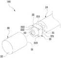
- FIG. 1 , 2 and 3are perspective views, exploded views and cross-sectional views of a first embodiment of the present invention, and a micro endoscope 100 is disclosed, which comprises:
- An image capturing device 20is disposed on the front end of the cable 10 .
- the image capturing device 20has a sensor 22 .
- the rear end of the sensor 22is electrically connected to the cable 10 , and the image capturing device 20 is connected to the image capturing device 20 .
- the front end of the sensor 22is provided with a lens 23, and the sensor 22 is a rectangular body, please refer to FIG.
- the sensor 22has four sides 221 and a front surface 222, and the lens 23 is laterally fixed to the front surface 222 of the inductor 22, so that the front surface of the inductor 22 is formed with four ends on the outer peripheral side of the lens 23.
- the image capturing device 20is provided with a plurality of self-illuminating members 25, and in the embodiment, the self-illuminating members 25 are respectively disposed on the side surface 221 of the inductor 22, wherein
- the self-luminous illuminating members 25are organic light emitting diodes (OLEDs) having a curved convex surface.
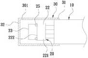
- An outer cover 30is made of a transparent optical material, and has a tubular body closed at one end.
- the outer cover 30defines an opening portion 31 along one end of the axis, and a front stop portion 32 is integrally formed at the other end.
- the opening portion 31is fixed on the cable 10 such that the image capturing device 20 is located in the outer cover 30.
- the front stop portion 32is a straight segment, and the front stop portion 32 is perpendicular to the axis of the outer cover 30.
- the inner wall 301 of the outer cover 30is respectively provided with an arcuate groove 302 corresponding to the self-illuminating member 25.
- the self-luminous light-emitting member 25is used to provide a light source. Since the self-luminous light-emitting members 25 are OLEDs, the OLED has the characteristics of a pixel, that is, a light source, and thus has a smaller size, a higher brightness, and a lower consumption than a common LED. The utility model has the advantages of low power and the like.
- the arcuate grooves 302 of the outer cover 30can be used to reflect and collect the light of the self-illuminating members 25 to increase the overall brightness for the inspection organ or the operation. It can assist in illuminating the internal position of the cavity of the human body, so that the image capturing device 20 can obtain more sufficient brightness when shooting, and can obtain a clearer image.
- FIG. 5FIG. 6, and FIG. 7, which are exploded views, cross-sectional views, and front views of a second embodiment of the present invention
- the second embodiment of the present inventionis different from the foregoing first embodiment in that Self-illuminating members 25 are respectively disposed on the end 223 of the inductor 22.
- FIG. 8is a cross-sectional view of a third embodiment of the present invention
- the third embodiment of the present inventionis different from the first embodiment in that the front stop portion 32 of the outer cover 30 is not flat.
- the front stop portion 32has a focusing characteristic such that the front stop portion 32 can replace the lens 23 for imaging.
- the self-illuminating material 25may be a self-luminous coating material, and the self-luminous coating material may be selected from one of a fluorescent coating material and a phosphorescent coating material.
- the self-luminous light emitting device 25is disposed on the image capturing device 20 in a coating manner. Periphery.
- the self-illuminating member 25 of the present inventionhas the advantages of small volume, high brightness, low power consumption, etc., so that the invention can be reduced to a diameter of less than 2 mm to meet the requirements of miniaturized endoscopes.
- the outer cover 30 of the present inventionis made of a transparent optical material, which is substantially closed at one end, and the front stop portion 32 is located in front of the lens 23, so that no gap can be achieved and the sealing degree is high. It has good waterproof performance and long service life.
Landscapes
- Physics & Mathematics (AREA)
- Life Sciences & Earth Sciences (AREA)
- Health & Medical Sciences (AREA)
- Surgery (AREA)
- Engineering & Computer Science (AREA)
- Optics & Photonics (AREA)
- Radiology & Medical Imaging (AREA)
- Heart & Thoracic Surgery (AREA)
- Veterinary Medicine (AREA)
- Biophysics (AREA)
- Nuclear Medicine, Radiotherapy & Molecular Imaging (AREA)
- Pathology (AREA)
- Public Health (AREA)
- General Health & Medical Sciences (AREA)
- Biomedical Technology (AREA)
- Animal Behavior & Ethology (AREA)
- Medical Informatics (AREA)
- Molecular Biology (AREA)
- Multimedia (AREA)
- General Physics & Mathematics (AREA)
- Astronomy & Astrophysics (AREA)
- Signal Processing (AREA)
- Endoscopes (AREA)
- Instruments For Viewing The Inside Of Hollow Bodies (AREA)
Abstract
Description
Translated fromChinese本发明与一种内视镜结构有关,尤其是指一种微型内视镜结构。The present invention relates to an endoscope structure, and more particularly to a miniature endoscope structure.
按,常见内视镜照明技术,例如台湾专利第M421091号新型专利案,于内视镜的前端设有多个LED,以提供光源进行导光作用,然而,由于LED的体积较大,使得内视镜的尺寸相对变大,往往超过直径3mm以上,故在使用过程中容易造成使用者的不适,且无法适用于孔道较小的地方。According to the common endoscope illumination technology, for example, the new patent of Taiwan Patent No. M421091, a plurality of LEDs are provided at the front end of the endoscope to provide a light source for guiding light. However, due to the large volume of the LED, the inner The size of the sight glass is relatively large, and often exceeds 3 mm in diameter. Therefore, it is easy to cause user discomfort during use, and it cannot be applied to a place with a small hole.
有鉴于此,乃有业者将LED去除,使该内视镜的直径缩减成为2mm以下,成为微型内视镜,然而由于微型内视镜的亮度不足,必须再外接光纤式照明穿入使用者腔体内,故在使用过程中亦会造成使用者的不适,且由于光纤本身无法进行较大的弯曲作业,使得操作上受到局限。In view of this, the manufacturer removes the LED, and the diameter of the endoscope is reduced to 2 mm or less to become a micro endoscope. However, since the brightness of the micro endoscope is insufficient, the external fiber optic illumination must be inserted into the user cavity. In the body, the user's discomfort is also caused during use, and the operation is limited due to the inability of the optical fiber itself to perform a large bending operation.
此外,一般内视镜前端的防护用镜片,为防止渗水,往往必须在于其周侧黏上封胶,以形成防水效果,惟封胶不仅使得制作过程繁杂,且仍会有渗水之虞。In addition, in order to prevent water seepage, the protective lens for the front end of the general endoscope often has to be glued on the circumferential side to form a waterproof effect, but the sealing glue not only makes the manufacturing process complicated, but also has water seepage.
是以,本案创作人观察到上述缺点后,认为现有的微型内视镜实有进一步改善的必要,而遂有本发明的产生。Therefore, after the creators of the present case observed the above shortcomings, it is considered that there is a need for further improvement of the existing micro endoscopes, and the present invention is produced.
发明内容Summary of the invention
本发明的主要目的在提供一种微型内视镜结构,其在微型化的尺寸内,可具有极佳的照明效果。SUMMARY OF THE INVENTION A primary object of the present invention is to provide a miniature endoscope structure that provides excellent illumination within a miniaturized size.
本发明的次要目的在提供一种微型内视镜结构,其构件简化,且具有极佳的防水性。A secondary object of the present invention is to provide a miniature endoscope structure with simplified components and polesGood water resistance.
为达上述主要目的,本发明所提供的微型内视镜结构,其包含有一电缆线;以及一取像装置,其设于该电缆线的前端上,该取像装置具有一感应器,该感应器后端与该电缆线电性连接,另该取像装置于该感应器前端设有一镜头,且该取像装置于该感应器上设有多个自体发光件;以及一外罩,其概呈一端封闭的管体,使该外罩沿轴线的一端形成一开口部,另一端则一体形成有一前挡部,其中,该开口部固设于该电缆线上,使该取像装置位于该外罩内,另该前挡部则恰位于该镜头的前方,以供保护该镜头。In order to achieve the above-mentioned main object, the micro endoscope structure provided by the present invention comprises a cable; and an image capturing device disposed on the front end of the cable, the image capturing device having an inductor, the sensing The rear end of the device is electrically connected to the cable, and the image capturing device is provided with a lens at the front end of the sensor, and the image capturing device is provided with a plurality of self-illuminating members on the sensor; and a cover, the outline of which is a tube body closed at one end, the outer cover is formed with an opening at one end of the axis, and the other end is integrally formed with a front stop portion, wherein the opening portion is fixed on the cable, so that the image capturing device is located in the outer cover The front stop is located just in front of the lens to protect the lens.
为达上述次要目的,本发明所提供的微型内视镜结构,该外罩为透明的光学材质所制成,并使得该前挡部位于该镜头的前方,以供保护该镜头。In order to achieve the above secondary object, the micro endoscope structure provided by the present invention is made of a transparent optical material, and the front end portion is located in front of the lens for protecting the lens.
作为优选方案,其中,该等自体发光件为自发光涂料,该自发光涂料选自荧光涂料或磷光涂料其中一种。Preferably, the self-luminous materials are self-luminous coatings, and the self-luminous coatings are selected from the group consisting of fluorescent coatings and phosphorescent coatings.
作为优选方案,其中,该等自体发光件为有机发光二极体(OLED)。Preferably, the self-luminous light-emitting members are organic light-emitting diodes (OLEDs).
作为优选方案,其中,该感应器为一矩形体,使该感应器具有四个侧面及一前面,该镜头为一圆柱体,该镜头横向固设于该感应器的前面,使该感应器的前面于该镜头外周侧形成有四个端部。Preferably, the sensor is a rectangular body, the sensor has four sides and a front surface, the lens is a cylinder, and the lens is laterally fixed to the front of the inductor, so that the sensor Four front ends are formed on the outer peripheral side of the lens.
作为优选方案,其中,该等自体发光件分别设于该感应器的侧面上。Preferably, the self-illuminating members are respectively disposed on sides of the inductor.
作为优选方案,其中,该等自体发光件分别设于该感应器的端部上。Preferably, the self-illuminating members are respectively disposed on the ends of the inductor.
作为优选方案,其中,该等自体发光件的表面呈弧形凸面。Preferably, the surface of the self-illuminating members has an arcuate convex surface.
作为优选方案,其中,该外罩内壁对应该等自体发光件分别设有一弧形凹槽。Preferably, the inner wall of the outer cover is respectively provided with an arcuate groove corresponding to the self-illuminating member.
作为优选方案,其中,该外罩的前挡部为一平直段,且该前挡部垂直于该外罩的轴线。Preferably, the front stop of the outer cover is a straight section, and the front stop is perpendicular to the axis of the outer cover.
作为优选方案,其中,该外罩的前挡部为非平直的不规则曲面或球面的其中一种。Preferably, the front stop of the outer cover is a non-flat irregular curved surface or a spherical surfaceone of them.
本发明的微型内视镜结构,透过该等自体发光件具有尺寸小且亮度高的特性,增加整体的照明亮度,并利用该取像装置在拍摄时取得更为清晰的影像,又该外罩为透明的光学材质所制成,其概呈一端封闭的管体,并使得该前挡部位于该镜头的前方,因此没有任何缝隙,密封度高,防水性能佳,可避免液体渗入该取像装置造成短路。The micro endoscope structure of the present invention has the characteristics of small size and high brightness through the self-illuminating members, thereby increasing the overall illumination brightness, and using the image capturing device to obtain a clearer image during shooting, and the cover Made of a transparent optical material, the tube body is closed at one end, and the front stop portion is located in front of the lens, so there is no gap, the sealing degree is high, the waterproof performance is good, and the liquid can be prevented from infiltrating into the image. The device caused a short circuit.
图1本发明的第一实施例的立体图。Figure 1 is a perspective view of a first embodiment of the present invention.
图2本发明的第一实施例的分解图。Figure 2 is an exploded view of the first embodiment of the present invention.
图3本发明的第一实施例的剖视图。Figure 3 is a cross-sectional view of a first embodiment of the present invention.
图4本发明的第一实施例的前视图。Figure 4 is a front elevational view of a first embodiment of the present invention.
图5本发明的第二实施例的分体图。Figure 5 is a partial view of a second embodiment of the present invention.
图6本发明的第二实施例的剖视图。Figure 6 is a cross-sectional view showing a second embodiment of the present invention.
图7本发明的第二实施例的前视图。Figure 7 is a front elevational view of a second embodiment of the present invention.
图8本发明的第三实施例的剖视图。Figure 8 is a cross-sectional view showing a third embodiment of the present invention.
请参阅图1、图2以及图3所示,为本发明的第一实施例的立体图、分解图及剖视图,揭示有一种微型内视镜100,其包含有:1 , 2 and 3 are perspective views, exploded views and cross-sectional views of a first embodiment of the present invention, and a
一电缆线10。A
一取像装置20,其设于该电缆线10的前端上,该取像装置20具有一感应器22,该感应器22后端与该电缆线10电性连接,另该取像装置20于该感应器22前端设有一镜头23,该感应器22为一矩形体,请搭配参阅图4所示,该感应器22具有四个侧面221及一前面222,且该镜头23横向固设于该感应器22的前面222,使该感应器22的前面于该镜头23外周侧形成有四个端部223,且该取像装置20于该感应器22上设有多个自体发光件25,于本实施例中,该等自体发光件25分别设于该感应器22的侧面221上,其中,该等自体发光件25为有机发光二极体(OLED),其表面呈弧形凸面。An
一外罩30,其为透明的光学材质所制成,其概呈一端封闭的管体,该使该外罩30沿轴线的一端形成一开口部31,另一端则一体形成有一前挡部32,其中,该开口部31固设于该电缆线10上,使该取像装置20位于该外罩30内,另该前挡部32为一平直段,该前挡部32垂直于该外罩30的轴线,且恰位于该镜头23的前方,以供保护该镜头23,又,于本实施例中,该外罩30的内壁301对应该等自体发光件25分别设有一弧形凹槽302。An
本发明于使用时,利用该等自体发光件25提供光源,由于该等自体发光件25为OLED,OLED具有像素即光源的特性,因此相较常见LED而言,具有尺寸小、亮度高且耗电量低等优点,该等自体发光件25发光后,该外罩30的弧形凹槽302可用以反射并聚集该等自体发光件25的光线,以增加整体的亮度,供检视器官或手术时,可以辅助照亮人体的腔内部位,以利该取像装置20在拍摄时获得更充足的亮度,而可取得更为清晰的影像。When the present invention is used, the self-luminous light-emitting
接着,请参阅图5、图6以及图7所示,为本发明的第二实施例的分解图、剖视图及前视图,本发明第二实施例与前述第一实施例不同之处在于该等自体发光件25分别设于该感应器22的端部223上。Next, referring to FIG. 5, FIG. 6, and FIG. 7, which are exploded views, cross-sectional views, and front views of a second embodiment of the present invention, the second embodiment of the present invention is different from the foregoing first embodiment in that Self-
接着,请参阅图8所示,为本发明的第三实施例的剖视图,本发明第三实施例与前述第一实施例不同之处在于该外罩30的前挡部32为非平直的不规则曲面或球面的其中一种,该前挡部32具有聚焦的特性,使得该前挡部32可替代该镜头23做成像作用。Next, referring to FIG. 8, which is a cross-sectional view of a third embodiment of the present invention, the third embodiment of the present invention is different from the first embodiment in that the
值得一提的是,该自体发光件25亦可为自发光涂料,自发光涂料可选自荧光涂料或磷光涂料其中一种,该自体发光件25以涂布方式设置于该取像装置20的周缘。It is to be noted that the self-
1、本发明的该等自体发光件25具有体积小、亮度高且耗电量低等优点,使本发明可缩小其直径至2mm以内,达到微型化内视镜的要求。1. The self-
2、本发明的该外罩30为透明的光学材质所制成,其概呈一端封闭的管体,并使得该前挡部32位于该镜头23的前方,因此可达到没有任何缝隙,密封度高,防水性能佳、使用寿命长。2. The
Claims (10)
Translated fromChinesePriority Applications (2)
| Application Number | Priority Date | Filing Date | Title |
|---|---|---|---|
| US16/621,042US20200112656A1 (en) | 2017-08-25 | 2017-09-19 | Miniature Endoscope |
| JP2019562378AJP2020526234A (en) | 2017-08-25 | 2017-09-19 | Micro endoscope structure |
Applications Claiming Priority (2)
| Application Number | Priority Date | Filing Date | Title |
|---|---|---|---|
| CN201710740455.0 | 2017-08-25 | ||
| CN201710740455.0ACN109419487A (en) | 2017-08-25 | 2017-08-25 | Micro-endoscope structure |
Publications (1)
| Publication Number | Publication Date |
|---|---|
| WO2019037179A1true WO2019037179A1 (en) | 2019-02-28 |
Family
ID=65439349
Family Applications (1)
| Application Number | Title | Priority Date | Filing Date |
|---|---|---|---|
| PCT/CN2017/102202CeasedWO2019037179A1 (en) | 2017-08-25 | 2017-09-19 | Microendoscope structure |
Country Status (4)
| Country | Link |
|---|---|
| US (1) | US20200112656A1 (en) |
| JP (1) | JP2020526234A (en) |
| CN (1) | CN109419487A (en) |
| WO (1) | WO2019037179A1 (en) |
Families Citing this family (6)
| Publication number | Priority date | Publication date | Assignee | Title |
|---|---|---|---|---|
| WO2018098465A1 (en) | 2016-11-28 | 2018-05-31 | Inventio, Inc. | Endoscope with separable, disposable shaft |
| USD1018844S1 (en) | 2020-01-09 | 2024-03-19 | Adaptivendo Llc | Endoscope handle |
| USD1051380S1 (en) | 2020-11-17 | 2024-11-12 | Adaptivendo Llc | Endoscope handle |
| USD1070082S1 (en) | 2021-04-29 | 2025-04-08 | Adaptivendo Llc | Endoscope handle |
| USD1031035S1 (en) | 2021-04-29 | 2024-06-11 | Adaptivendo Llc | Endoscope handle |
| USD1066659S1 (en) | 2021-09-24 | 2025-03-11 | Adaptivendo Llc | Endoscope handle |
Citations (5)
| Publication number | Priority date | Publication date | Assignee | Title |
|---|---|---|---|---|
| US20080221388A1 (en)* | 2007-03-09 | 2008-09-11 | University Of Washington | Side viewing optical fiber endoscope |
| CN102316784A (en)* | 2009-02-12 | 2012-01-11 | 皇家飞利浦电子股份有限公司 | Interventional instrument with illumination means |
| CN106678437A (en)* | 2015-11-10 | 2017-05-17 | 天津澳特斯阀门制造有限公司 | Valve interior observing device provided with self-luminous industrial endoscope |
| CN106725254A (en)* | 2017-02-18 | 2017-05-31 | 蚌埠市圆周率电子科技有限公司 | A kind of medical pro-skin type endoscope |
| CN106943115A (en)* | 2016-10-08 | 2017-07-14 | 上海安清医疗器械有限公司 | Endoscope leading end portion, endoscope focus adjustment method and endoscope |
Family Cites Families (14)
| Publication number | Priority date | Publication date | Assignee | Title |
|---|---|---|---|---|
| CN100421613C (en)* | 2004-11-16 | 2008-10-01 | 医电科技股份有限公司 | Video Intubation Assist Device |
| KR200386923Y1 (en)* | 2005-03-11 | 2005-06-16 | 유메디칼 주식회사 | rigid laryngeal endoscope for observing lower direction |
| TW201028125A (en)* | 2009-01-19 | 2010-08-01 | hui-yu Zhang | Micro image pick-up apparatus |
| MX350734B (en)* | 2010-09-08 | 2017-09-15 | Covidien Lp | Catheter with imaging assembly. |
| CN203483391U (en)* | 2013-04-26 | 2014-03-19 | 吴修菊 | Uterine cavity checker |
| CN203555714U (en)* | 2013-07-17 | 2014-04-23 | 珠海迈德豪医用科技有限公司 | Endoscope with preposed lighting light source |
| JP6469392B2 (en)* | 2013-09-11 | 2019-02-13 | 株式会社半導体エネルギー研究所 | Endoscope device |
| US9829698B2 (en)* | 2015-08-31 | 2017-11-28 | Panasonic Corporation | Endoscope |
| JP5909304B1 (en)* | 2015-08-31 | 2016-04-26 | パナソニック株式会社 | Endoscope |
| CN105212883B (en)* | 2015-10-15 | 2016-12-07 | 汕头大学医学院 | A kind of esophageal endoscope sampler |
| CN205514493U (en)* | 2016-03-11 | 2016-08-31 | 圻逸科技股份有限公司 | Improved Structure of Camera Lens Device for Endoscope |
| CN205885394U (en)* | 2016-05-09 | 2017-01-18 | 佛山市第一人民医院 | Antifog system of scope |
| CN106510604A (en)* | 2016-11-30 | 2017-03-22 | 天津恒宇医疗科技有限公司 | Medical endoscopic probe |
| CN208551746U (en)* | 2017-08-25 | 2019-03-01 | 长绩科技股份有限公司 | Micro endoscope structure |
- 2017
- 2017-08-25CNCN201710740455.0Apatent/CN109419487A/enactivePending
- 2017-09-19USUS16/621,042patent/US20200112656A1/ennot_activeAbandoned
- 2017-09-19JPJP2019562378Apatent/JP2020526234A/enactivePending
- 2017-09-19WOPCT/CN2017/102202patent/WO2019037179A1/ennot_activeCeased
Patent Citations (5)
| Publication number | Priority date | Publication date | Assignee | Title |
|---|---|---|---|---|
| US20080221388A1 (en)* | 2007-03-09 | 2008-09-11 | University Of Washington | Side viewing optical fiber endoscope |
| CN102316784A (en)* | 2009-02-12 | 2012-01-11 | 皇家飞利浦电子股份有限公司 | Interventional instrument with illumination means |
| CN106678437A (en)* | 2015-11-10 | 2017-05-17 | 天津澳特斯阀门制造有限公司 | Valve interior observing device provided with self-luminous industrial endoscope |
| CN106943115A (en)* | 2016-10-08 | 2017-07-14 | 上海安清医疗器械有限公司 | Endoscope leading end portion, endoscope focus adjustment method and endoscope |
| CN106725254A (en)* | 2017-02-18 | 2017-05-31 | 蚌埠市圆周率电子科技有限公司 | A kind of medical pro-skin type endoscope |
Also Published As
| Publication number | Publication date |
|---|---|
| CN109419487A (en) | 2019-03-05 |
| JP2020526234A (en) | 2020-08-31 |
| US20200112656A1 (en) | 2020-04-09 |
Similar Documents
| Publication | Publication Date | Title |
|---|---|---|
| WO2019037179A1 (en) | Microendoscope structure | |
| JP4704386B2 (en) | Endoscope | |
| CN101380219B (en) | Capsule endoscope | |
| US7821569B2 (en) | Converter lens attachment with built-in light source for compact digital camera | |
| US20060170328A1 (en) | Capsule endoscope | |
| EP2011428A4 (en) | Borescope | |
| ATE450849T1 (en) | OBSERVATION SYSTEM. | |
| TWI749328B (en) | Miniature camera module | |
| JP2008206624A (en) | Tip part for ultrafine diameter electronic endoscope | |
| CN208551746U (en) | Micro endoscope structure | |
| TWM556136U (en) | Structure of miniature endoscope | |
| TWM572199U (en) | Endoscope image capturing module with fluorescence coated LED light source | |
| TWI665999B (en) | Miniature endoscope structure | |
| JP2006255247A (en) | Capsule endoscope | |
| CN103845152B (en) | A kind of visual earpick tool | |
| CN101930153B (en) | External microscope lens unit | |
| JP2005204944A (en) | Endoscope | |
| CN211796359U (en) | Endoscope with a detachable handle | |
| CN218630346U (en) | Probe lens | |
| TWI674876B (en) | Endoscope image capturing module with fluorescent coated LED light source | |
| US7819537B2 (en) | Flash unit | |
| US8313428B2 (en) | Side-viewing endoscope structure | |
| CN218995767U (en) | Corner probe macro lens | |
| CN221765821U (en) | High brightness optical projection lens | |
| JP2006197986A (en) | Capsule endoscope |
Legal Events
| Date | Code | Title | Description |
|---|---|---|---|
| 121 | Ep: the epo has been informed by wipo that ep was designated in this application | Ref document number:17922886 Country of ref document:EP Kind code of ref document:A1 | |
| ENP | Entry into the national phase | Ref document number:2019562378 Country of ref document:JP Kind code of ref document:A | |
| NENP | Non-entry into the national phase | Ref country code:DE | |
| 122 | Ep: pct application non-entry in european phase | Ref document number:17922886 Country of ref document:EP Kind code of ref document:A1 |