WO2019035427A1 - Shovel and supporting device cooperating with shovel - Google Patents
Shovel and supporting device cooperating with shovelDownload PDFInfo
- Publication number
- WO2019035427A1 WO2019035427A1PCT/JP2018/030107JP2018030107WWO2019035427A1WO 2019035427 A1WO2019035427 A1WO 2019035427A1JP 2018030107 WJP2018030107 WJP 2018030107WWO 2019035427 A1WO2019035427 A1WO 2019035427A1
- Authority
- WO
- WIPO (PCT)
- Prior art keywords
- voice
- setting
- shovel
- display
- image
- Prior art date
- Legal status (The legal status is an assumption and is not a legal conclusion. Google has not performed a legal analysis and makes no representation as to the accuracy of the status listed.)
- Ceased
Links
Images


Classifications
- E—FIXED CONSTRUCTIONS
- E02—HYDRAULIC ENGINEERING; FOUNDATIONS; SOIL SHIFTING
- E02F—DREDGING; SOIL-SHIFTING
- E02F9/00—Component parts of dredgers or soil-shifting machines, not restricted to one of the kinds covered by groups E02F3/00 - E02F7/00
- E02F9/26—Indicating devices
- E02F9/267—Diagnosing or detecting failure of vehicles
- E02F9/268—Diagnosing or detecting failure of vehicles with failure correction follow-up actions
- E—FIXED CONSTRUCTIONS
- E02—HYDRAULIC ENGINEERING; FOUNDATIONS; SOIL SHIFTING
- E02F—DREDGING; SOIL-SHIFTING
- E02F9/00—Component parts of dredgers or soil-shifting machines, not restricted to one of the kinds covered by groups E02F3/00 - E02F7/00
- E02F9/26—Indicating devices
- E02F9/264—Sensors and their calibration for indicating the position of the work tool
- E02F9/265—Sensors and their calibration for indicating the position of the work tool with follow-up actions (e.g. control signals sent to actuate the work tool)
- E—FIXED CONSTRUCTIONS
- E02—HYDRAULIC ENGINEERING; FOUNDATIONS; SOIL SHIFTING
- E02F—DREDGING; SOIL-SHIFTING
- E02F9/00—Component parts of dredgers or soil-shifting machines, not restricted to one of the kinds covered by groups E02F3/00 - E02F7/00
- E02F9/06—Floating substructures as supports
- B—PERFORMING OPERATIONS; TRANSPORTING
- B60—VEHICLES IN GENERAL
- B60K—ARRANGEMENT OR MOUNTING OF PROPULSION UNITS OR OF TRANSMISSIONS IN VEHICLES; ARRANGEMENT OR MOUNTING OF PLURAL DIVERSE PRIME-MOVERS IN VEHICLES; AUXILIARY DRIVES FOR VEHICLES; INSTRUMENTATION OR DASHBOARDS FOR VEHICLES; ARRANGEMENTS IN CONNECTION WITH COOLING, AIR INTAKE, GAS EXHAUST OR FUEL SUPPLY OF PROPULSION UNITS IN VEHICLES
- B60K35/00—Instruments specially adapted for vehicles; Arrangement of instruments in or on vehicles
- B60K35/10—Input arrangements, i.e. from user to vehicle, associated with vehicle functions or specially adapted therefor
- B—PERFORMING OPERATIONS; TRANSPORTING
- B60—VEHICLES IN GENERAL
- B60K—ARRANGEMENT OR MOUNTING OF PROPULSION UNITS OR OF TRANSMISSIONS IN VEHICLES; ARRANGEMENT OR MOUNTING OF PLURAL DIVERSE PRIME-MOVERS IN VEHICLES; AUXILIARY DRIVES FOR VEHICLES; INSTRUMENTATION OR DASHBOARDS FOR VEHICLES; ARRANGEMENTS IN CONNECTION WITH COOLING, AIR INTAKE, GAS EXHAUST OR FUEL SUPPLY OF PROPULSION UNITS IN VEHICLES
- B60K35/00—Instruments specially adapted for vehicles; Arrangement of instruments in or on vehicles
- B60K35/20—Output arrangements, i.e. from vehicle to user, associated with vehicle functions or specially adapted therefor
- B60K35/21—Output arrangements, i.e. from vehicle to user, associated with vehicle functions or specially adapted therefor using visual output, e.g. blinking lights or matrix displays
- B60K35/22—Display screens
- B—PERFORMING OPERATIONS; TRANSPORTING
- B60—VEHICLES IN GENERAL
- B60K—ARRANGEMENT OR MOUNTING OF PROPULSION UNITS OR OF TRANSMISSIONS IN VEHICLES; ARRANGEMENT OR MOUNTING OF PLURAL DIVERSE PRIME-MOVERS IN VEHICLES; AUXILIARY DRIVES FOR VEHICLES; INSTRUMENTATION OR DASHBOARDS FOR VEHICLES; ARRANGEMENTS IN CONNECTION WITH COOLING, AIR INTAKE, GAS EXHAUST OR FUEL SUPPLY OF PROPULSION UNITS IN VEHICLES
- B60K35/00—Instruments specially adapted for vehicles; Arrangement of instruments in or on vehicles
- B60K35/20—Output arrangements, i.e. from vehicle to user, associated with vehicle functions or specially adapted therefor
- B60K35/26—Output arrangements, i.e. from vehicle to user, associated with vehicle functions or specially adapted therefor using acoustic output
- B—PERFORMING OPERATIONS; TRANSPORTING
- B60—VEHICLES IN GENERAL
- B60R—VEHICLES, VEHICLE FITTINGS, OR VEHICLE PARTS, NOT OTHERWISE PROVIDED FOR
- B60R1/00—Optical viewing arrangements; Real-time viewing arrangements for drivers or passengers using optical image capturing systems, e.g. cameras or video systems specially adapted for use in or on vehicles
- B60R1/20—Real-time viewing arrangements for drivers or passengers using optical image capturing systems, e.g. cameras or video systems specially adapted for use in or on vehicles
- B60R1/22—Real-time viewing arrangements for drivers or passengers using optical image capturing systems, e.g. cameras or video systems specially adapted for use in or on vehicles for viewing an area outside the vehicle, e.g. the exterior of the vehicle
- B60R1/23—Real-time viewing arrangements for drivers or passengers using optical image capturing systems, e.g. cameras or video systems specially adapted for use in or on vehicles for viewing an area outside the vehicle, e.g. the exterior of the vehicle with a predetermined field of view
- E—FIXED CONSTRUCTIONS
- E02—HYDRAULIC ENGINEERING; FOUNDATIONS; SOIL SHIFTING
- E02F—DREDGING; SOIL-SHIFTING
- E02F3/00—Dredgers; Soil-shifting machines
- E02F3/04—Dredgers; Soil-shifting machines mechanically-driven
- E02F3/28—Dredgers; Soil-shifting machines mechanically-driven with digging tools mounted on a dipper- or bucket-arm, i.e. there is either one arm or a pair of arms, e.g. dippers, buckets
- E02F3/30—Dredgers; Soil-shifting machines mechanically-driven with digging tools mounted on a dipper- or bucket-arm, i.e. there is either one arm or a pair of arms, e.g. dippers, buckets with a dipper-arm pivoted on a cantilever beam, i.e. boom
- E02F3/32—Dredgers; Soil-shifting machines mechanically-driven with digging tools mounted on a dipper- or bucket-arm, i.e. there is either one arm or a pair of arms, e.g. dippers, buckets with a dipper-arm pivoted on a cantilever beam, i.e. boom working downwardly and towards the machine, e.g. with backhoes
- E—FIXED CONSTRUCTIONS
- E02—HYDRAULIC ENGINEERING; FOUNDATIONS; SOIL SHIFTING
- E02F—DREDGING; SOIL-SHIFTING
- E02F3/00—Dredgers; Soil-shifting machines
- E02F3/04—Dredgers; Soil-shifting machines mechanically-driven
- E02F3/28—Dredgers; Soil-shifting machines mechanically-driven with digging tools mounted on a dipper- or bucket-arm, i.e. there is either one arm or a pair of arms, e.g. dippers, buckets
- E02F3/36—Component parts
- E02F3/42—Drives for dippers, buckets, dipper-arms or bucket-arms
- E02F3/43—Control of dipper or bucket position; Control of sequence of drive operations
- E02F3/435—Control of dipper or bucket position; Control of sequence of drive operations for dipper-arms, backhoes or the like
- E—FIXED CONSTRUCTIONS
- E02—HYDRAULIC ENGINEERING; FOUNDATIONS; SOIL SHIFTING
- E02F—DREDGING; SOIL-SHIFTING
- E02F9/00—Component parts of dredgers or soil-shifting machines, not restricted to one of the kinds covered by groups E02F3/00 - E02F7/00
- E02F9/16—Cabins, platforms, or the like, for drivers
- E02F9/166—Cabins, platforms, or the like, for drivers movable, tiltable or pivoting, e.g. movable seats, dampening arrangements of cabins
- E—FIXED CONSTRUCTIONS
- E02—HYDRAULIC ENGINEERING; FOUNDATIONS; SOIL SHIFTING
- E02F—DREDGING; SOIL-SHIFTING
- E02F9/00—Component parts of dredgers or soil-shifting machines, not restricted to one of the kinds covered by groups E02F3/00 - E02F7/00
- E02F9/26—Indicating devices
- E02F9/264—Sensors and their calibration for indicating the position of the work tool
- G—PHYSICS
- G06—COMPUTING OR CALCULATING; COUNTING
- G06F—ELECTRIC DIGITAL DATA PROCESSING
- G06F3/00—Input arrangements for transferring data to be processed into a form capable of being handled by the computer; Output arrangements for transferring data from processing unit to output unit, e.g. interface arrangements
- G06F3/01—Input arrangements or combined input and output arrangements for interaction between user and computer
- G—PHYSICS
- G06—COMPUTING OR CALCULATING; COUNTING
- G06F—ELECTRIC DIGITAL DATA PROCESSING
- G06F3/00—Input arrangements for transferring data to be processed into a form capable of being handled by the computer; Output arrangements for transferring data from processing unit to output unit, e.g. interface arrangements
- G06F3/14—Digital output to display device ; Cooperation and interconnection of the display device with other functional units
- G06F3/1423—Digital output to display device ; Cooperation and interconnection of the display device with other functional units controlling a plurality of local displays, e.g. CRT and flat panel display
- G—PHYSICS
- G06—COMPUTING OR CALCULATING; COUNTING
- G06F—ELECTRIC DIGITAL DATA PROCESSING
- G06F3/00—Input arrangements for transferring data to be processed into a form capable of being handled by the computer; Output arrangements for transferring data from processing unit to output unit, e.g. interface arrangements
- G06F3/16—Sound input; Sound output
- G06F3/167—Audio in a user interface, e.g. using voice commands for navigating, audio feedback
- G—PHYSICS
- G10—MUSICAL INSTRUMENTS; ACOUSTICS
- G10L—SPEECH ANALYSIS TECHNIQUES OR SPEECH SYNTHESIS; SPEECH RECOGNITION; SPEECH OR VOICE PROCESSING TECHNIQUES; SPEECH OR AUDIO CODING OR DECODING
- G10L15/00—Speech recognition
- G—PHYSICS
- G10—MUSICAL INSTRUMENTS; ACOUSTICS
- G10L—SPEECH ANALYSIS TECHNIQUES OR SPEECH SYNTHESIS; SPEECH RECOGNITION; SPEECH OR VOICE PROCESSING TECHNIQUES; SPEECH OR AUDIO CODING OR DECODING
- G10L15/00—Speech recognition
- G10L15/22—Procedures used during a speech recognition process, e.g. man-machine dialogue
- B—PERFORMING OPERATIONS; TRANSPORTING
- B60—VEHICLES IN GENERAL
- B60K—ARRANGEMENT OR MOUNTING OF PROPULSION UNITS OR OF TRANSMISSIONS IN VEHICLES; ARRANGEMENT OR MOUNTING OF PLURAL DIVERSE PRIME-MOVERS IN VEHICLES; AUXILIARY DRIVES FOR VEHICLES; INSTRUMENTATION OR DASHBOARDS FOR VEHICLES; ARRANGEMENTS IN CONNECTION WITH COOLING, AIR INTAKE, GAS EXHAUST OR FUEL SUPPLY OF PROPULSION UNITS IN VEHICLES
- B60K2360/00—Indexing scheme associated with groups B60K35/00 or B60K37/00 relating to details of instruments or dashboards
- B60K2360/148—Instrument input by voice
- B—PERFORMING OPERATIONS; TRANSPORTING
- B60—VEHICLES IN GENERAL
- B60K—ARRANGEMENT OR MOUNTING OF PROPULSION UNITS OR OF TRANSMISSIONS IN VEHICLES; ARRANGEMENT OR MOUNTING OF PLURAL DIVERSE PRIME-MOVERS IN VEHICLES; AUXILIARY DRIVES FOR VEHICLES; INSTRUMENTATION OR DASHBOARDS FOR VEHICLES; ARRANGEMENTS IN CONNECTION WITH COOLING, AIR INTAKE, GAS EXHAUST OR FUEL SUPPLY OF PROPULSION UNITS IN VEHICLES
- B60K35/00—Instruments specially adapted for vehicles; Arrangement of instruments in or on vehicles
- B60K35/80—Arrangements for controlling instruments
- B60K35/81—Arrangements for controlling instruments for controlling displays
- G—PHYSICS
- G10—MUSICAL INSTRUMENTS; ACOUSTICS
- G10L—SPEECH ANALYSIS TECHNIQUES OR SPEECH SYNTHESIS; SPEECH RECOGNITION; SPEECH OR VOICE PROCESSING TECHNIQUES; SPEECH OR AUDIO CODING OR DECODING
- G10L15/00—Speech recognition
- G10L15/22—Procedures used during a speech recognition process, e.g. man-machine dialogue
- G10L2015/223—Execution procedure of a spoken command
Definitions
- the machine guidance device 50outputs information output by at least one of the boom angle sensor S1, the arm angle sensor S2, the bucket angle sensor S3, the vehicle body inclination sensor S4, the GPS device D1, the communication device T1, the input device 42, the voice input device 44, etc. Receive Then, various calculations are performed based on the received information and the information stored in the storage device 47, and the calculation result is output to at least one of the voice output device 43, the display device 40, and the like.
- the machine guidance device 50calculates, for example, the height of the work site of the attachment, and the control command according to the size of the distance between the height of the work site and the predetermined target height is the voice output device 43 and the display device Output to at least one of 40.
- the voice output device 43 that has received the control commandoutputs a sound representing the magnitude of the distance.
- the display device 40 that has received the control commanddisplays an image representing the magnitude of the distance.
- the target heightis a concept including the target depth, and is, for example, a height input by the operator as a vertical distance to the reference point after the work site is in contact with the reference point.
- the reference pointstypically have known latitude, longitude and altitude.
- the target setting unit 504may display the geometrical information on the display device 40 using the information on the position of the predetermined part of the drilling attachment at each of two time points.
- Geometrical informationis information on the result of surveying by the shovel PS.
- the target setting unit 504displays, for example, an angle formed between a virtual straight line passing through these two coordinate points and a horizontal plane as geometrical information based on the position coordinates of the tip of the bucket 6 at each of two time points Display on the device 40.
- the two coordinate pointsmay be displayed as geometrical information as they are, or the horizontal distance and the vertical distance between the two coordinate points may be displayed as geometrical information.
- the first time point of the two time pointsis the time when the predetermined condition is satisfied as described above.
- the image displayed in the hierarchy information display area 41nis switched to the fifth V image.
- the image displayed in the hierarchical information display area 41nis switched to the fifth Z1 image (not shown).
- the machine guidance device 50determines whether the time during which the operator does not speak exceeds the predetermined time (step ST4).
- the machine guidance device 50may control an indicator 60 provided on the top of the display device 40, as shown in FIG.
- the indicator 60is, for example, an LED, and lights or extinguishes the LED to notify the operator whether or not the voice recognition function is operating.
- the left diagram of FIG. 13shows the state in which the indicator 60 is off when the voice recognition function is not operating, and the right diagram of FIG. 13 shows the indicator 60 being lit when the voice recognition function is operating. Show the status.
Landscapes
- Engineering & Computer Science (AREA)
- General Engineering & Computer Science (AREA)
- Mechanical Engineering (AREA)
- Theoretical Computer Science (AREA)
- Multimedia (AREA)
- Physics & Mathematics (AREA)
- Human Computer Interaction (AREA)
- Combustion & Propulsion (AREA)
- Transportation (AREA)
- Chemical & Material Sciences (AREA)
- Mining & Mineral Resources (AREA)
- Structural Engineering (AREA)
- Civil Engineering (AREA)
- General Physics & Mathematics (AREA)
- Health & Medical Sciences (AREA)
- Audiology, Speech & Language Pathology (AREA)
- General Health & Medical Sciences (AREA)
- Computational Linguistics (AREA)
- Acoustics & Sound (AREA)
- Component Parts Of Construction Machinery (AREA)
- Operation Control Of Excavators (AREA)
Abstract
Translated fromJapaneseDescription
Translated fromJapanese本開示は、ショベル、及び、ショベルと協働する支援装置に関する。The present disclosure relates to a shovel and a support device that cooperates with the shovel.
ショベルを操作する操作者は、アタッチメントによる掘削等の作業を効率的且つ正確に行うために、熟練した操作技術が要求される。そこで、ショベルの操作経験が少ない操作者でも正確に作業できるように、ショベルの操作をガイドするシステム(以下、「マシンガイダンスシステム」とする。)が知られている(例えば、特許文献1参照)。The operator who operates the shovel is required to have a skillful operation technique in order to carry out the work such as excavation by the attachment efficiently and accurately. Therefore, there is known a system (hereinafter referred to as a "machine guidance system") for guiding the operation of a shovel so that an operator with little experience in operating the shovel can correctly perform the operation (for example, see Patent Document 1). .
マシンガイダンスシステムを有効に利用するには、目標面等の入力等の各種設定を事前に行う必要がある。これらの設定は、通常、ショベルの運転室内に設置された表示装置に表示される設定画面を通じて行われる。設定画面の表示は、例えば、表示装置の近くに設けられたハードウェアスイッチを押すことで実現されている(例えば、特許文献2参照)。In order to use the machine guidance system effectively, it is necessary to perform various settings such as input of a target surface in advance. These settings are usually performed through a setting screen displayed on a display device installed in the cab of the shovel. The display of the setting screen is realized, for example, by pressing a hardware switch provided near the display device (see, for example, Patent Document 2).
しかしながら、上述の構成では、ショベルの操作者は、設定画面を表示させるために表示装置のところまで手を伸ばしてハードウェアスイッチを押す必要がある。特に、マシンガイダンスシステムによる施工支援等の情報通信技術(Information and Communications Technology (ICT))を利用した施工支援に関する設定画面(以下、「ICT設定画面」とする。)は、頻繁に利用される場合がある。そのため、設定画面の表示のためにハードウェアスイッチを押すことに操作者が煩わしさを感じるおそれがある。However, in the above-described configuration, the operator of the shovel needs to reach for the display and press the hardware switch to display the setting screen. In particular, the setting screen (hereinafter referred to as "ICT setting screen") regarding construction support using Information and Communications Technology (ICT) such as construction support by machine guidance system is frequently used. There is. Therefore, the operator may feel bothersome to press the hardware switch to display the setting screen.
そこで、操作者がICT設定画面をより簡単に操作できるようにするショベルを提供することが望ましい。Therefore, it is desirable to provide a shovel that allows the operator to more easily operate the ICT setting screen.
本発明の実施形態に係るショベルは、下部走行体と、前記下部走行体に旋回自在に搭載された上部旋回体と、前記上部旋回体に搭載された運転室と、前記運転室内に設けられた表示装置と、前記運転室内に設けられた音声入力装置と、音声認識機能を備えた制御装置と、を有し、前記表示装置は、施工支援に関する設定画面を表示し、前記制御装置は、前記音声入力装置を通じて入力された音声を認識し、認識結果に応じて前記設定画面に関する処理を実行する。The shovel according to the embodiment of the present invention is provided in a lower traveling body, an upper swing body rotatably mounted on the lower traveling body, a driver's cab mounted on the upper swing body, and the driver's cab A display device, a voice input device provided in the driver's cab, and a control device having a voice recognition function, the display device displays a setting screen regarding construction support, and the control device The voice input through the voice input device is recognized, and processing related to the setting screen is executed according to the recognition result.
上述の手段により、操作者がICT設定画面をより簡単に操作できるようにするショベルが提供される。By the above-described means, a shovel is provided which enables the operator to more easily operate the ICT setting screen.
以下、図面を参照して本発明の実施形態に係るショベルについて説明する。各図面において、同一構成部分には同一符号を付し、重複した説明を省略する場合がある。Hereinafter, a shovel according to an embodiment of the present invention will be described with reference to the drawings. In the drawings, the same components are denoted by the same reference numerals, and redundant description may be omitted.
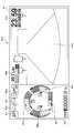
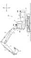
図1は、本発明の実施形態に係るショベルPSを例示する側面図である。ショベルPSの下部走行体1には、旋回機構2を介して旋回自在に上部旋回体3が搭載されている。上部旋回体3には、ブーム4が取り付けられている。ブーム4の先端には、アーム5が取り付けられている。アーム5の先端には、エンドアタッチメント(作業部位)としてバケット6が取り付けられている。FIG. 1 is a side view illustrating a shovel PS according to an embodiment of the present invention. An upper revolving
ブーム4、アーム5及びバケット6は、アタッチメントの一例として掘削アタッチメントを構成している。そして、ブーム4は、ブームシリンダ7により駆動され、アーム5は、アームシリンダ8により駆動され、バケット6は、バケットシリンダ9により駆動される。ブーム4にはブーム角度センサS1が取り付けられ、アーム5にはアーム角度センサS2が取り付けられ、バケット6にはバケット角度センサS3が取り付けられている。ブーム角度センサS1、アーム角度センサS2及びバケット角度センサS3を集合的に「姿勢センサ」と称することもある。姿勢センサは、アタッチメントの姿勢を検出する。例えば、アタッチメントの作業部位の位置を導き出すことができるようにするためである。The
ブーム角度センサS1は、ブーム4の回動角度であるブーム角度を検出する。ブーム角度センサS1は、例えば、水平面に対する傾斜を検出して、上部旋回体3に対するブーム4の回動角度を検出する加速度センサである。The boom angle sensor S1 detects a boom angle which is a rotation angle of the
アーム角度センサS2は、アーム5の回動角度であるアーム角度を検出する。アーム角度センサS2は、例えば、水平面に対する傾斜を検出して、ブーム4に対するアーム5の回動角度を検出する加速度センサである。The arm angle sensor S <b> 2 detects an arm angle which is a rotation angle of the
バケット角度センサS3は、バケット6の回動角度であるバケット角度を検出する。バケット角度センサS3は、例えば、水平面に対する傾斜を検出して、アーム5に対するバケット6の回動角度を検出する加速度センサである。The bucket angle sensor S3 detects a bucket angle which is a rotation angle of the
ブーム角度センサS1、アーム角度センサS2及びバケット角度センサS3は、可変抵抗器を利用したポテンショメータ、対応する油圧シリンダのストローク量を検出するストロークセンサ、又は、連結回りの回動角度を検出するロータリエンコーダ等であってもよい。ブーム角度センサS1、アーム角度センサS2及びバケット角度センサS3の少なくとも1つは、加速度センサとジャイロセンサの組み合わせであってもよい。The boom angle sensor S1, the arm angle sensor S2 and the bucket angle sensor S3 are a potentiometer using a variable resistor, a stroke sensor for detecting a stroke amount of a corresponding hydraulic cylinder, or a rotary encoder for detecting a rotation angle around connection Or the like. At least one of the boom angle sensor S1, the arm angle sensor S2, and the bucket angle sensor S3 may be a combination of an acceleration sensor and a gyro sensor.
上部旋回体3には、エンジン11等の動力源及び車体傾斜センサS4等が搭載されている。車体傾斜センサS4は、上部旋回体3の傾斜角を検出する。車体傾斜センサS4は、例えば、水平面に対する傾斜を検出して、上部旋回体3の傾斜角を検出する加速度センサである。The upper revolving
上部旋回体3には、撮像装置80が設けられている。撮像装置80は、ショベルPSの左方の空間を撮像する左カメラ80L、右方の空間を撮像する右カメラ80R、及び、後方の空間を撮像するバックカメラ80Bを含む。左カメラ80L、右カメラ80R及びバックカメラ80Bのそれぞれは、例えば、CCD又はCMOS等の撮像素子を有するデジタルカメラであり、撮影した画像を運転室10内に設けられている表示装置40に送る。The
上部旋回体3には、運転室10が設けられている。運転室10内には、コントローラ30、表示装置40、音声出力装置43及び記憶装置47等が設けられている。また、運転室10には、GPS装置(GNSS受信機)D1及び通信装置T1が取り付けられている。GPS装置D1は、ショベルPSの位置を検出し、検出した位置に関するデータをコントローラ30に供給する。通信装置T1は、外部との通信を制御し、外部から取得したデータをコントローラ30に供給する。通信装置T1は、例えば、衛星通信網、携帯電話通信網及び無線LAN等の少なくとも1つを介して外部から情報を取得できるように構成されている。The
コントローラ30は、ショベルPSの駆動制御を行う主制御部として機能する制御装置である。本実施形態では、コントローラ30は、CPU及び内部メモリを含む演算処理装置で構成されている。コントローラ30の各種機能は、CPUが内部メモリに格納されているプログラムを実行することで実現される。The
コントローラ30は、ショベルPSの操作をガイドする制御装置であるマシンガイダンス装置50としても機能する。マシンガイダンス装置50は、例えば、施工支援としてマシンガイダンス機能を実行する場合、操作者が設定した目標地形の表面である目標面とアタッチメントの作業部位との距離等、アタッチメントの作業部位と目標面との相対的な関係を表す作業情報を視覚的に或いは聴覚的に操作者に知らせる。目標面とアタッチメントの作業部位との距離は、例えば、エンドアタッチメントとしてのバケット6の先端(爪先)、バケット6の背面、又は、エンドアタッチメントとしてのブレーカの先端等と目標面との間の距離である。マシンガイダンス装置50は、表示装置40及び音声出力装置43等の少なくとも1つを介して、作業情報を操作者に認識させてショベルPSの操作をガイドする。マシンガイダンス装置50は、ショベルPSを自動的に或いは半自動的に動作させるマシンコントロール機能を実行してもよい。例えば、マシンガイダンス装置50は、施工支援としてマシンコントロール機能を実行する場合、操作者が掘削操作を行っているときに、目標面とバケット6の先端位置とが合致するようにブーム4、アーム5及びバケット6の少なくとも1つの動きをアシストする。より具体的には、例えば、操作者がアーム閉じ操作を行っているときにブームシリンダ7及びバケットシリンダ9の少なくとも一方を自動的に伸縮させて目標面とバケット6の先端位置とを合致させる。この場合、操作者は、1本の操作レバーを操作するだけで、ブーム4、アーム5及びバケット6を同時に動かして目標面とバケット6の先端位置とを合わせながら掘削作業を行うことができる。The
図1の例では、マシンガイダンス装置50はコントローラ30に組み込まれているが、コントローラ30の外部に設けられていてもよい。この場合、マシンガイダンス装置50は、コントローラ30と同様、CPU及び内部メモリを含む演算処理装置で構成される。そして、マシンガイダンス装置50の各種機能は、CPUが内部メモリに格納されたプログラムを実行することで実現される。In the example of FIG. 1, the
表示装置40は、コントローラ30又はマシンガイダンス装置50からの指令に応じて各種作業情報を含む画像を表示する。表示装置40は、例えば、マシンガイダンス装置50に接続される液晶ディスプレイである。The
音声出力装置43は、マシンガイダンス装置50からの音声出力指令に応じて各種音声情報を出力する。音声出力装置43は、例えば、マシンガイダンス装置50に接続されるスピーカを含む。また、音声出力装置43は、ブザー等の警報器であってもよい。The
記憶装置47は、各種情報を記憶するための装置である。図1の例では、記憶装置47として、半導体メモリ等の不揮発性記憶媒体が採用されている。The
ゲートロックレバー49は、ショベルPSが誤って操作されるのを防止する機構であり、運転室10のドアと運転席との間に設けられている。ゲートロックレバー49は、運転室10からの操作者の退出を妨げるように引き上げられたときに各種操作装置を有効にし、操作者の退出が可能となるように押し下げられたときに各種操作装置を無効にする。The
図2A及び図2Bは、ショベルPSに搭載される基本システムの構成例を示す図である。図2Bの構成は、操作者が携帯するスマートフォン等の携帯端末である支援装置SDとショベルPSとが協働している点で、図2Aの構成と異なる。表示装置40は、マシンガイダンス装置50から供給される作業情報等を含む画像を表示する。表示装置40は、例えば、CAN若しくはLIN等の通信ネットワークを構成するケーブル又は専用線等を介してマシンガイダンス装置50を含むコントローラ30に接続されている。FIG. 2A and FIG. 2B are diagrams showing a configuration example of a basic system mounted on a shovel PS. The configuration of FIG. 2B differs from the configuration of FIG. 2A in that a support device SD, which is a portable terminal such as a smartphone carried by an operator, cooperates with a shovel PS. The
表示装置40は、画像表示部41に表示する画像を生成する変換処理部40aを有する。変換処理部40aは、撮像装置80から得られる画像データに基づき、画像表示部41上に表示する、実写画像を含む画像を生成する。表示装置40には、左カメラ80L、右カメラ80R及びバックカメラ80Bのそれぞれから画像データが入力される。The
変換処理部40aは、例えば、コントローラ30から表示装置40に入力される各種データのうち画像表示部41に表示させるデータを画像信号に変換する。コントローラ30から表示装置40に入力されるデータは、例えば、エンジン冷却水の温度を示すデータ、作動油の温度を示すデータ、尿素水の残量を示すデータ、及び、燃料の残量を示すデータ等の少なくとも1つを含む。The
変換処理部40aは、変換した画像信号を画像表示部41に出力し、実写画像及び各種データ等の少なくとも1つに基づいて生成した画像を画像表示部41に表示させる。変換処理部40aは、表示装置40ではなく、例えば、コントローラ30に設けられてもよい。この場合、撮像装置80は、コントローラ30に接続される。The
表示装置40は、入力装置42を備えていてもよい。入力装置42は、ショベルPSの操作者がマシンガイダンス装置50又はコントローラ30に各種情報を入力するための装置である。図2A及び図2Bの例では、入力装置42は、スイッチパネルに設けられた押しボタンスイッチである。入力装置42は、例えば、メンブレンスイッチであってもよく、タッチパネルであってもよい。具体的には、入力装置42は、表示切換ボタン42a及び方向ボタン42bを有する。The
表示切換ボタン42aは、画像表示部41に表示される画像を切り換えるためのボタンである。表示切換ボタン42aは、押される度に、画像表示部41に表示される画面を切り換える。画像表示部41に表示される画面は、メイン画面及び情報表示・設定画面を含む。The
方向ボタン42bは、方向を入力する操作部の一例である。図2A及び図2Bの例では、上下左右の4方向を入力できるように構成された十字ボタンが方向ボタン42bとして採用されている。方向ボタン42bは、上ボタン、下ボタン、左ボタン及び右ボタンの独立した4つのボタンの組み合わせであってもよい。操作者は、方向ボタン42bの操作により、画面を切り替えたり、画面内に表示されるカーソルを移動させたり、カーソル移動により選択された項目の数値を変更したりすることができる。The
音声入力装置44は、ショベルPSの操作者がマシンガイダンス装置50を含むコントローラ30に各種情報を音声で入力するための装置である。図2A及び図2Bの例では、音声入力装置44は、運転室10内に取り付けられたマイクロフォンである。音声入力装置44は、ショベルPSの周囲で発せられた音を拾えるようにショベルPSの外側に向けて上部旋回体3に設置されたマイクロフォンであってもよい。The
コントローラ30は、図2Bに示すように、操作者が携帯する支援装置SDが搭載している音声入力装置44Dを通じて入力された音声を利用できるように構成されていてもよい。図2Bの支援装置SDは、例えば、スマートフォン、タブレットPC又はボイスレコーダ等の携帯端末であり、コントローラ30D、表示装置40D、音声入力装置44D、通信装置T1D及び記憶装置47Dを含む。コントローラ30D、表示装置40D、音声入力装置44D、通信装置T1D及び記憶装置47Dは、それぞれ、ショベルPSに搭載されているコントローラ30、表示装置40、音声入力装置44、通信装置T1及び記憶装置47と同様に機能する。As shown in FIG. 2B, the
表示装置40は、蓄電池70から電力の供給を受けて動作する。蓄電池70は、エンジン11のオルタネータ11a(発電機)で発電した電力で充電される。蓄電池70の電力は、コントローラ30及び表示装置40以外のショベルPSの電装品72等にも供給される。エンジン11のスタータ11bは、蓄電池70からの電力で駆動されてエンジン11を始動させる。The
エンジン11は、エンジンコントローラ(ECU)74により制御される。エンジン11の回転軸は、メインポンプ14及びパイロットポンプ15のそれぞれの回転軸に連結されている。ECU74は、エンジン11の状態を示す各種データ(例えば、水温センサ11cで検出される冷却水温を示すデータ等)をコントローラ30に向けて送信する。コントローラ30は、記憶部30aにこれらのデータを蓄積し、必要に応じて表示装置40に送信する。The
メインポンプ14は、作動油ラインを介して作動油をコントロールバルブ17に供給するための油圧ポンプである。メインポンプ14は、例えば、斜板式可変容量型油圧ポンプである。The
パイロットポンプ15は、パイロットラインを介して各種油圧制御機器に作動油を供給するための油圧ポンプである。パイロットポンプ15は、例えば、固定容量型油圧ポンプである。但し、パイロットポンプ15は、省略されてもよい。この場合、パイロットポンプ15により実現されていた機能は、メインポンプ14によって実現されてもよい。The
コントロールバルブ17は、ショベルPSにおける油圧システムを制御する油圧制御装置である。コントロールバルブ17は、例えば、1又は複数の油圧アクチュエータに、メインポンプ14が吐出する作動油を選択的に供給するように構成されている。油圧アクチュエータは、例えば、ブームシリンダ7、アームシリンダ8、バケットシリンダ9、走行用油圧モータ及び旋回用油圧モータ等を含む。The
操作装置26は、操作者が油圧アクチュエータを操作するために用いる装置であり、運転室10内に設けられている。操作装置26が操作されると、対応する流量制御弁のパイロットポートにパイロットポンプ15から作動油が供給される。パイロットポートには、操作装置26の操作内容に応じた圧力の作動油が供給される。操作内容は、例えば、操作方向及び操作量を含む。The operating
コントローラ30は、ショベルPS全体の動作を制御する。コントローラ30は、ゲートロックレバー49が押し下げられている状態では、ゲートロック弁49aを閉状態とし、ゲートロックレバー49が引き上げられている状態では、ゲートロック弁49aを開状態とする。ゲートロック弁49aは、コントロールバルブ17と操作装置26との間の油路に設けられている切換弁である。ゲートロック弁49aは、コントローラ30からの指令に応じて開閉する。但し、ゲートロック弁49aは、ゲートロックレバー49と機械的に接続され、ゲートロックレバー49の動作に応じて開閉してもよい。The
ゲートロック弁49aは、閉状態において、コントロールバルブ17と操作装置26との間の作動油の流れを遮断して操作装置26を無効にする。また、ゲートロック弁49aは、開状態において、コントロールバルブ17と操作装置26との間で作動油を連通させて操作装置26を有効にする。The
コントローラ30は、ゲートロック弁49aが開状態となり、操作装置26が有効になった状態で、圧力センサ15a、15bによって検出されるパイロット圧から、操作装置26の操作内容を検出する。The
また、コントローラ30は、例えば以下で説明するような各種データを取得する。コントローラ30が取得したデータは、記憶部30aに格納される。In addition, the
メインポンプ14のレギュレータ14aは、斜板角度を示すデータをコントローラ30に対して出力する。吐出圧力センサ14bは、メインポンプ14の吐出圧力を示すデータをコントローラ30に対して出力する。作動油タンクとメインポンプ14との間の管路に設けられている油温センサ14cは、管路を流れる作動油の温度を表すデータをコントローラ30に対して出力する。圧力センサ15a、15bは、操作装置26が操作された際に生成されるパイロット圧を検出し、検出したパイロット圧を示すデータをコントローラ30に対して出力する。The
操作装置26としての操作レバーには、入力装置42の別の一例としてのスイッチボタン26Sが設けられている。操作者は、操作レバーを操作しながらスイッチボタン26Sを操作することで、コントローラ30に対して指令信号を出力できる。The operation lever as the
ショベルPSの運転室10内には、エンジン回転数調整ダイヤル75が設けられている。エンジン回転数調整ダイヤル75は、エンジン11の回転数を調整するためのダイヤルである。操作者は、例えば、エンジン回転数調整ダイヤル75を回すことで、エンジン回転数を段階的に切り換えることができる。本実施形態では、エンジン回転数調整ダイヤル75は、SPモード、Hモード、Aモード及びアイドリングモードの4段階で操作者がエンジン回転数を切り換えることができるように設けられている。エンジン回転数調整ダイヤル75は、エンジン回転数の設定状態を示すデータをコントローラ30に対して出力する。図2A及び図2Bは、エンジン回転数調整ダイヤル75によりHモードが選択された状態を示している。An engine
SPモードは、作業量を優先させる場合に選択される回転数モードであり、最も高いエンジン回転数を利用する。Hモードは、作業量と燃費を両立させる場合に選択される回転数モードであり、二番目に高いエンジン回転数を利用する。Aモードは、燃費を優先させながら低騒音でショベルPSを稼働させる場合に選択される回転数モードであり、三番目に高いエンジン回転数を利用する。アイドリングモードは、エンジンをアイドリング状態にする場合に選択される回転数モードであり、最も低いエンジン回転数を利用する。エンジン11は、エンジン回転数調整ダイヤル75で設定された回転数モードのエンジン回転数で一定回転数に制御される。The SP mode is a rotation speed mode selected when giving priority to the amount of work, and utilizes the highest engine rotation speed. The H mode is a rotational speed mode that is selected in order to balance work amount and fuel consumption, and utilizes the second highest engine rotational speed. The A mode is a rotational speed mode selected when operating the shovel PS with low noise while giving priority to fuel consumption, and utilizes the third highest engine rotational speed. The idling mode is a rotation speed mode selected when the engine is idling, and utilizes the lowest engine rotation speed. The
次に、図3Aを参照し、マシンガイダンス装置50に設けられている各種機能について説明する。図3Aは、ショベルPSに搭載されるコントローラ30の構成例を示す図である。Next, various functions provided in the
コントローラ30は、ショベルPS全体の動作の制御に加えて、マシンガイダンス装置50によるガイダンスを行うか否かを制御する。具体的には、コントローラ30は、ショベルPSが休止中であると判定したときは、マシンガイダンス装置50によるガイダンスを中止するように、ガイダンス中止指令をマシンガイダンス装置50に出力する。The
コントローラ30は、オートアイドルストップ指令をECU74に対して出力する際に、ガイダンス中止指令をマシンガイダンス装置50に出力してもよい。或いは、コントローラ30は、ゲートロックレバー49が押し下げられた状態にあると判定した場合に、ガイダンス中止指令をマシンガイダンス装置50に出力してもよい。The
マシンガイダンス装置50は、ブーム角度センサS1、アーム角度センサS2、バケット角度センサS3、車体傾斜センサS4、GPS装置D1、通信装置T1、入力装置42及び音声入力装置44等の少なくとも1つが出力する情報を受信する。そして、受信した情報と記憶装置47に記憶された情報とに基づいて各種演算を実行し、その演算結果を音声出力装置43及び表示装置40等の少なくとも1つに出力する。The
マシンガイダンス装置50は、例えば、アタッチメントの作業部位の高さを算出し、その作業部位の高さと所定の目標高さとの間の距離の大きさに応じた制御指令を音声出力装置43及び表示装置40の少なくとも一方に出力する。制御指令を受けた音声出力装置43はその距離の大きさを表す音を出力する。制御指令を受けた表示装置40はその距離の大きさを表す画像を表示する。目標高さは、目標深さを含む概念であり、例えば、基準点に作業部位を接触させた後でその基準点に対する鉛直距離として操作者が入力する高さである。基準点は、典型的には、既知の緯度、経度及び高度を有する。以下では、表示装置40に表示されるアタッチメントの作業部位の高さと目標高さとの間の距離の大きさに関する情報を「作業部位ガイダンス情報」とする。操作者は、作業部位ガイダンス情報を見ることでその距離の大きさの推移を確認しながら作業を進めることができる。The
マシンガイダンス装置50は、上述のガイダンスを行うため、傾斜角算出部501、高さ算出部502、距離算出部503、目標設定部504、音声認識部505及び音声操作部506等を含む。The
傾斜角算出部501は、車体傾斜センサS4からの検出信号に基づいて水平面に対する上部旋回体3の傾斜角であるショベルPSの傾斜角を算出する。The inclination
高さ算出部502は、基準面に対するアタッチメントの作業部位の高さを算出する。この算出は、傾斜角算出部501が算出した傾斜角と、ブーム角度センサS1、アーム角度センサS2及びバケット角度センサS3のそれぞれの検出信号から算出されたブーム角度、アーム角度及びバケット角度とに基づく。基準面は、例えば、ショベルPSが位置する平面を含む仮想平面である。図3Aの例では、バケット6の先端で掘削を行うため、バケット6の先端(爪先)がアタッチメントの作業部位に相当する。バケット6の背面で土砂を均すような作業をするときにはバケット6の背面がアタッチメントの作業部位に相当する。The
距離算出部503は、高さ算出部502が算出した作業部位の高さと目標高さとの間の距離を算出する。図3Aの例では、高さ算出部502が算出したバケット6の先端(爪先)の高さと目標高さとの距離を算出する。The
目標設定部504は、マシンガイダンス機能又はマシンコントロール機能で用いる目標値を設定する。目標設定部504は、例えば、2つの時点のそれぞれにおける掘削アタッチメントの所定部位の位置に関する情報に基づいて目標値を設定する。例えば、2つの時点のそれぞれにおけるバケット6の先端の位置座標に基づき、それら2つの座標点を通る仮想直線と水平面との間に形成される角度を算出し、その角度を目標法面角度として設定する。2つの時点はそれぞれ、所定の条件が満たされた時点である。例えば、所定のスイッチが押された時点、又は、掘削アタッチメントが静止したまま所定時間が経過した時点等を含む。目標法面角度はゼロ度を含んでいてもよい。The
目標設定部504は、2つの時点のそれぞれにおける掘削アタッチメントの所定部位の位置に関する情報を用いて表示装置40に幾何学的情報を表示してもよい。幾何学的情報は、ショベルPSによる測量の結果に関する情報である。目標設定部504は、例えば、2つの時点のそれぞれにおけるバケット6の先端の位置座標に基づき、それら2つの座標点を通る仮想直線と水平面との間に形成される角度を幾何学的情報として表示装置40に表示する。2つの座標点をそのまま幾何学的情報として表示してもよく、2つの座標点の間の水平距離及び鉛直距離を幾何学的情報として表示してもよい。本実施形態では、2つの時点のうちの第1の時点は、上述のように所定の条件が満たされた時点である。一方、2つの時点のうちの第2の時点は、現在時点である。このように、幾何学的情報は、第1の時点で登録された所定部位の座標点と、現在時点における所定部位の座標点との位置関係を操作者に認識させるために表示される。The
音声認識部505は、ショベルPSの操作者が発した音声を認識する。図3Aの例では、音声認識エンジンを用い、音声入力装置44を通じて入力された音声を文字列に変換する。音声認識部505は、認識した音声を表す文字列を表示装置40に表示させてもよい。操作者が発した音声とマシンガイダンス装置50が認識した音声とが一致しているか否かを操作者に確認させるためである。音声認識エンジンは、1又は複数の音声認識辞書を利用し、入力された音声を文字列に変換する。音声認識辞書は、例えば、記憶装置47に記憶されている。音声認識辞書は、関西弁、東北弁又は九州弁といった方言毎に用意されていてもよい。この場合、音声認識部505は、例えば、GPS装置D1の出力に基づいて検出されたショベルPSの現在位置に基づき、使用する音声認識辞書を切り換えてもよい。音声認識部505は、例えば、ショベルPSが東北地方に位置すると判定した場合、東北弁に適した音声認識辞書を使用してもよい。また、音声認識部505は、入力された音声の特徴(アクセント及びイントネーション等)に基づいて操作者が使用する方言を識別するように構成されていてもよい。この場合、音声認識部505は、操作者が使用する方言に合わせて音声認識辞書を切り換えてもよい。The
音声認識部505は、ショベルPSの操作者を識別するように構成されていてもよい。この場合、音声認識部505は、声紋認証技術を用いてもよい。音声認識部505は、例えば、所定の合言葉が発せられたときに、取得した声紋データと既登録の声紋データとを照合し、発話者が既登録の操作者であるか否かを判定する。The
音声認識部505は、学習機能を備えていてもよい。音声認識部505は、例えば、操作者が音声の入力をやり直したと判断した場合、次回以降、1回目に入力された音声を、2回目に入力された音声として認識するように学習してもよい。例えば、音声認識部505は、1回目に入力された癖のある音声を把握できなかった後で、2回目に入力された音声を認識できた場合、次回以降においては、1回目に入力された癖のある音声を、2回目に入力された音声と同じ音声として認識するように学習してもよい。その結果、音声認識部505は、最初は認識できなかった癖のある音声を認識できるようになる。また、音声認識部505は、例えば、第1時点で認識した音声が所定の登録コマンドであると判定できなかった場合であって、その後に、登録コマンドに対応する処理を開始させるための操作が手動で行われた場合、第1時点で認識した音声が登録コマンドを表していたと判断してもよい。そして、音声認識部505は、次回以降、第1時点で認識した音声と同じ音声を認識した場合には、登録コマンドが発話されたと見なし、その登録コマンドに対応する処理を自動的に開始させてもよい。登録コマンドは、所定の処理を開始させるためのきっかけとなる既登録の音声であり、例えば、メイン画面の表示を開始させるための既登録の音声「メイン表示」を含む。この場合、登録コマンドに対応する処理を開始させるための手動操作は、例えば、表示切換ボタン42aの押下である。The
音声認識部505は、声紋認証技術等を用いて操作者を識別している場合には、操作者の音声の特徴を操作者毎に学習してもよい。The
マシンガイダンス装置50は、運転室10内に設置された音声入力装置44ではなく支援装置SDに搭載された音声入力装置44Dを通じて入力された音声を利用できるように構成されていてもよい。この場合、支援装置SDは、図3Bに示すように、音声認識部505Dを備えていてもよい。図3Bは、音声認識部505Dを備えたコントローラ30Dを有する支援装置SDの構成例を示す。この構成では、音声認識部505Dは、ショベルPSに設けられたコントローラ30が有する音声認識部505と同様に機能する。そして、音声認識部505Dは、通信装置T1Dを通じて音声認識結果をコントローラ30に向けて送信する。コントローラ30は、通信装置T1を介し、支援装置SDから送信された音声認識結果を受信する。この構成により、ショベルPSの操作者は、運転室10内にいる場合には、運転室10内に設置された音声入力装置44を通じて音声を入力でき、運転室10から外に出た場合には、支援装置SDに搭載された音声入力装置44Dを通じて音声を入力できる。但し、支援装置SDに搭載された音声入力装置44Dを利用できる場合、運転室内に設置された音声入力装置44は省略されてもよい。この場合、ショベルPSの操作者は、運転室10内にいる場合であっても、支援装置SDに搭載された音声入力装置44Dを通じて音声を入力できる。また、支援装置SDに搭載された音声入力装置44Dを利用する場合であっても、音声の認識は、音声認識部505で行われてもよい。この場合、音声入力装置44Dは、通信装置T1Dを介し、音声認識結果ではなく、音声情報をコントローラ30に向けて送信するだけでよい。The
音声操作部506は、音声認識結果に応じて各種操作を行う。図3Aの例では、音声操作部506は、音声認識部505が音声操作部506を起動させるための所定の音声(以下、「起動音声」とする。)を認識した場合に起動する。また、音声操作部506は、操作者からの音声入力が所定時間無かった場合に停止する。音声認識部505が音声操作部506を停止させるための所定の音声(以下、「停止音声」とする。)を認識した場合に停止してもよい。図3Bの音声認識部505Dが起動音声又は停止音声を認識した場合も同様である。起動音声は、例えば「すみとも起動」である。停止音声は、例えば「すみとも終了」である。The
音声操作部506は、マシンコントロール機能を開始させるための所定の音声(以下、「MC音声」とする。)を認識した場合にマシンコントロール機能を開始させてもよい。MC音声は、例えば、「MC(エムシー)オン」である。この構成により、ショベルPSの操作者は、操作レバーの先端に設けられたスイッチボタン26Sを操作することなく、マシンコントロール機能を開始させることができる。The
音声認識部505は、例えば、起動音声を認識した場合、取得した声紋データと既登録の声紋データとを照合し、発話者が既登録の操作者であるか否かを判定する。そして、音声操作部506は、音声認識部505により既登録の操作者であると判定された場合に限り起動するように構成されていてもよい。支援装置SDにおける音声認識部505Dが、発話者が既登録の操作者であるか否かを判定する場合も同様である。For example, when recognizing the activation voice, the
音声操作部506は、例えば、音声認識結果に応じてICT設定画面に関する処理を実行する。ICT設定画面に関する処理は、例えば、図5の階層情報表示領域41nに表示される画像の切り換え、主要領域R2における設定項目の選択、及び、設定項目の設定値の入力等を含む。The
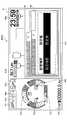
次に、表示装置40に表示される画面の構成例について説明する。図4は、表示装置40の画像表示部41に表示されるメイン画面41Vの一例を示す図である。Next, a configuration example of a screen displayed on the
メイン画面41Vは、日時表示領域41a、走行モード表示領域41b、アタッチメント表示領域41c、平均燃費表示領域41d、エンジン制御状態表示領域41e、エンジン作動時間表示領域41f、冷却水温表示領域41g、燃料残量表示領域41h、回転数モード表示領域41i、尿素水残量表示領域41j、作動油温表示領域41k及びカメラ画像表示領域41mを含む。走行モード表示領域41b、アタッチメント表示領域41c、エンジン制御状態表示領域41e及び回転数モード表示領域41iのそれぞれは、ショベルPSの設定状態を表示する設定状態表示部の例である。平均燃費表示領域41d、エンジン作動時間表示領域41f、冷却水温表示領域41g、燃料残量表示領域41h、尿素水残量表示領域41j及び作動油温表示領域41kのそれぞれは、ショベルPSの運転状態を表示する運転状態表示部の例である。The
日時表示領域41aは、現在の日時を表示する領域である。走行モード表示領域41bは、現在の走行モードを表すアイコンを表示する領域である。アタッチメント表示領域41cは、現在装着されているアタッチメントを表すアイコンを表示する領域である。平均燃費表示領域41dは、現在の平均燃費を表示する領域である。エンジン制御状態表示領域41eは、エンジン11の制御状態を表すアイコンを表示する領域である。冷却水温表示領域41gは、現在のエンジン冷却水の温度状態を表示する領域である。燃料残量表示領域41hは、燃料タンク55に貯蔵されている燃料の残量状態を表示する領域である。回転数モード表示領域41iは、現在の回転数モードを表示する領域である。尿素水残量表示領域41jは、尿素水タンクに貯蔵されている尿素水の残量状態を表示する領域である。作動油温表示領域41kは、作動油タンク内の作動油の温度状態を表示する領域である。カメラ画像表示領域41mは、カメラ画像を表示する領域である。The date and
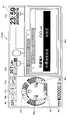
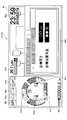
次に、図5を参照し、表示装置40に表示される情報表示・設定画面について説明する。図5は、表示装置40の画像表示部41に表示される情報表示・設定画面41VCの一例を示す図である。情報表示・設定画面41VCは、カメラ画像表示領域41mの代わりに階層情報表示領域41nを有する点で図4のメイン画面41Vと相違する。しかしながら、情報表示・設定画面41VCは、その他の点でメイン画面41Vと共通する。そのため、共通部分の説明を省略し、相違部分を詳説する。Next, the information display / setting screen displayed on the
階層情報表示領域41nは、階層構造を有する情報を表示する領域である。図5の例では、階層情報表示領域41nは、1階層につき5つのタブを用いて2層の階層構造を有する情報を表示する。The hierarchical
図5は、階層情報表示領域41nで特定の設定項目の設定値が変更される様子を示している。具体的には、図5は、操作者が表示切換ボタン42a及び方向ボタン42bを用いて2層目の5番目のタブ内にある設定項目の設定値を変更する様子を示している。FIG. 5 shows how setting values of specific setting items are changed in the hierarchy
操作者は、最初に、表示切換ボタン42aを押して表示装置40に情報表示・設定画面41VCを表示させる。具体的には、メイン画面41Vが表示されている状態、すなわち、階層情報表示領域41nではなくカメラ画像表示領域41mが表示されている状態で、表示切換ボタン42aを押してカメラ画像表示領域41mを階層情報表示領域41nに切り換える。そのとき、情報表示・設定画面41VCの階層情報表示領域41nには、1層目の1番目のタブ「A」が選択状態であり、2~5番目の4つのタブ「B」~「E」が非選択状態である第1画像(図示せず。)が表示される。The operator first presses the
図5では、1層目の5番目のタブ「E」が選択状態である画像が階層情報表示領域41nに表示されている。破線で囲まれた領域は、各種情報が表示される主要領域R1を表している。破線は実際には表示されない。In FIG. 5, an image in which the fifth tab “E” of the first layer is in the selected state is displayed in the hierarchy
第1画像が階層情報表示領域41nに表示された画面は、例えば、燃費情報画面である。燃費情報画面の主要領域R1には、例えば、燃費(例えば単位時間当たりの燃料消費量)の過去の推移等が表示される。The screen on which the first image is displayed in the hierarchy
第1画像が表示された状態で操作者が方向ボタン42bの右部分を押すと、階層情報表示領域41nに表示される画像は、第2画像(図示せず。)に切り換えられる。第2画像では、1層目の2番目のタブ「B」が選択状態である。第2画像が階層情報表示領域41nに表示された画面は、例えば、機械状態情報画面である。機械状態情報画面の主要領域R1には、例えば、エンジン回転数等の過去の推移等が表示される。When the operator presses the right portion of the
第2画像が表示された状態で操作者が方向ボタン42bの右部分を押すと、階層情報表示領域41nに表示される画像は、第3画像(図示せず。)に切り換えられる。また、第3画像が表示された状態で操作者が方向ボタン42bの右部分を押すと、階層情報表示領域41nに表示される画像は、第4画像(図示せず。)に切り換えられる。When the operator presses the right portion of the
第3画像では、1層目の3番目のタブ「C」が選択状態である。第4画像では、1層目の4番目のタブ「D」が選択状態である。第3画像が階層情報表示領域41nに表示された画面は、例えば、メンテナンス情報画面であり、第4画像が階層情報表示領域41nに表示された画面は、例えば、アタッチメントオプション情報画面である。In the third image, the third tab "C" in the first layer is in the selected state. In the fourth image, the fourth tab "D" of the first layer is in the selected state. The screen in which the third image is displayed in the hierarchy
第4画像が表示された状態で操作者が方向ボタン42bの右部分を押すと、階層情報表示領域41nに表示される画像は、第5画像(図示せず。)に切り換えられる。第5画像では、1層目の5番目のタブ「E」が選択状態である。第5画像は、主要領域R1に2層目の5つのタブを含む。第5画像が階層情報表示領域41nに表示された画面は、例えば、マシンガイダンス装置50等の情報通信技術を利用した施工支援に関する設定画面(ICT設定画面)である。施工支援は、例えば、マシンガイダンス機能を実行してショベルPSによる施工を支援すること、マシンコントロール機能を実行してショベルPSによる施工を支援すること、及び、ペイロードに関する情報を表示してショベルPSによる施工を支援すること、の少なくとも1つを含む。マシンガイダンス機能を実行してショベルPSによる施工を支援することは、例えば、アタッチメントの作業部位と目標面との相対的な位置関係を表示してショベルPSによる施工を支援することを含む。ペイロードに関する情報は、例えば、ショベルPSと協働するダンプトラックの最大積載量、及び、そのダンプトラックに積載可能な被掘削物の残重量等を含む。ペイロードに関するICT設定画面は、「4トン」又は「10トン」といったダンプトラックの種別(ダンプID)、及び、「砂」、「粘度」又は「コンクリート」といった被掘削物の種別(マテリアルID)等を設定項目として含む。ダンプトラックの種別は、例えば、ダンプトラックの最大積載量を導き出すために利用され、被掘削物の種別は、例えば、ダンプトラックに積載可能な被掘削物の残重量を導き出すために利用される。When the operator presses the right portion of the
第5画像が表示された状態で操作者が方向ボタン42bの右部分を押すと、階層情報表示領域41nに表示される画像は、第1画像に切り換えられる。一方、第5画像が表示された状態で操作者が方向ボタン42bの下部分を押すと、階層情報表示領域41nに表示される画像は、第5V画像(図示せず。)に切り換えられる。When the operator presses the right portion of the
第5V画像では、2層目の1番目のタブ「V」が選択状態であり、2~5番目の4つのタブ「W」~「Z」が非選択状態である。一点鎖線で囲まれた領域は、各種設定項目の設定値が表示される主要領域R2を表している。一点鎖線は実際には表示されない。第5V画像が階層情報表示領域41nに表示された画面は、例えば、ICT設定画面のうちの1つである目標面設定画面である。目標面設定画面では、例えば、目標高さ及び目標法面角度等が設定される。In the fifth V image, the first tab “V” in the second layer is in the selected state, and the second to fifth four tabs “W” to “Z” are in the non-selected state. An area surrounded by an alternate long and short dash line represents a main area R2 in which setting values of various setting items are displayed. The dashed dotted line is not actually displayed. The screen on which the fifth V image is displayed in the hierarchy
第5V画像が表示された状態で操作者が方向ボタン42bの右部分を押すと、階層情報表示領域41nに表示される画像は、第5W画像(図示せず。)に切り換えられる。第5W画像では、2層目の2番目のタブ「W」が選択状態である。主要領域R2には、第5V画像の場合と同様に、設定項目の設定値が表示される。第5W画像が階層情報表示領域41nに表示された画面は、例えば、ICT設定画面のうちの1つであるブザー設定画面である。ブザー設定画面では、例えば、ブザー音の周波数(高低)及び音量等が設定される。When the operator presses the right portion of the
第5W画像が表示された状態で操作者が方向ボタン42bの右部分を押すと、階層情報表示領域41nに表示される画像は、第5X画像(図示せず。)に切り換えられる。第5X画像が表示された状態で操作者が方向ボタン42bの右部分を押すと、階層情報表示領域41nに表示される画像は、第5Y画像(図示せず。)に切り換えられる。第5Y画像が表示された状態で操作者が方向ボタン42bの右部分を押すと、階層情報表示領域41nに表示される画像は、第5Z画像(図示せず。)に切り換えられる。第5X画像では、2層目の3番目のタブ「X」が選択状態である。第5Y画像では、2層目の4番目のタブ「Y」が選択状態である。第5Z画像では、2層目の5番目のタブ「Z」が選択状態である。第5X画像~第5Z画像のそれぞれの主要領域R2には、第5V画像の場合と同様に、設定項目の設定値が表示される。When the operator presses the right portion of the
第5X画像が階層情報表示領域41nに表示された画面は、例えば、ICT設定画面のうちの1つである測量設定画面である。測量設定画面では、例えば、測量モードの使用を有効にするか否か等が設定される。第5Y画像が階層情報表示領域41nに表示された画面は、例えば、ICT設定画面のうちの1つである基準点設定画面である。基準点設定画面では、例えば、バケットベンチセット機能の使用を有効にするか否か等が設定される。バケットベンチセット機能は、バケット6に関するベンチマーク(基準点)を設定する機能である。バケットベンチセット機能が有効の場合、操作者は、バケット6の爪先を基準点に接触させた状態でスイッチボタン26Sの1つであるバケットベンチセットボタン(図示せず。)を押すことで、そのときのバケット6の爪先の座標を原点として登録できる。第5Z画像が階層情報表示領域41nに表示された画面は、例えば、ICT設定画面のうちの1つである旋回角度基準設定画面である。旋回角度基準設定画面では、例えば、旋回ベンチセット機能の使用を有効にするか否か等が設定される。旋回ベンチセット機能は、旋回角度の基準を設定する機能である。旋回ベンチセット機能が有効の場合、操作者は、旋回操作によって上部旋回体3を所望の方向に方向付けた状態でスイッチボタン26Sの1つである旋回ベンチセットボタン(図示せず。)を押すことで、そのときの旋回角度をゼロ度として登録できる。The screen on which the fifth X image is displayed in the hierarchy
第5Z画像が表示された状態で操作者が方向ボタン42bの右部分を押すと、階層情報表示領域41nに表示される画像は、第5V画像に切り換えられる。一方、第5Z画像が表示された状態で操作者が方向ボタン42bの下部分を押すと、階層情報表示領域41nに表示される画像は、第5Z1画像(図示せず。)に切り換えられる。When the operator presses the right portion of the
第5Z1画像では、2層目の5番目のタブ「Z」の主要領域R2における1番目の設定項目が選択状態であり、2番目の設定項目が非選択状態である。In the fifth Z1 image, the first setting item in the main area R2 of the fifth tab “Z” in the second layer is in the selected state, and the second setting item is in the non-selected state.
第5Z1画像が表示された状態で操作者が方向ボタン42bの下部分を押すと、階層情報表示領域41nに表示される画像は、第5Z2画像に切り換えられる。図5は、第5Z2画像が表示された状態を示している。第5Z2画像では、2層目の5番目のタブ「Z」の主要領域R2における2番目の設定項目が選択状態であり、1番目の設定項目が非選択状態である。選択状態にある2番目の設定項目は、カーソルで指示されていてもよい。When the operator presses the lower portion of the
第5Z2画像が表示された状態で操作者が方向ボタン42bの上部分又は下部分を押すと、階層情報表示領域41nに表示される画像は、第5Z1画像に切り換えられる。一方、第5Z2画像が表示された状態で操作者が方向ボタン42bの右部分を押すと、2番目の設定項目の設定値が所定の増分だけインクリメント(増大)される。第5Z2画像が表示された状態で操作者が方向ボタン42bの左部分を押すと、2番目の設定項目の設定値が所定の減分だけデクリメント(低減)される。When the operator presses the upper or lower portion of the
上述の説明では、例として第5V画像から第5Z画像を挙げたが、各画像における設定項目は、統合されてもよく、分離されてもよい。また、各画像に別の設定項目が追加されてもよい。In the above description, although the 5th V image to the 5th Z image are mentioned as an example, the setting items in each image may be integrated or separated. In addition, another setting item may be added to each image.
以上のような手順で操作者は任意の設定項目の設定値を変更できる。具体的には、操作者は、表示切換ボタン42aを押して情報表示・設定画面41VCを表示させた後で、方向ボタン42bの右部分を4回押すことでICT設定画面を表示させる。方向ボタン42bの左部分を1回押すことでICT設定画面を表示させてもよい。その後、操作者は、方向ボタン42bの下部分を1回押し、更に、方向ボタン42bの右部分を4回押すことで旋回角度基準設定画面を表示させる。方向ボタン42bの下部分を1回押し、更に、方向ボタン42bの左部分を1回押すことで旋回角度基準設定画面を表示させてもよい。その後、操作者は、方向ボタン42bの下部分を2回押すことで旋回角度基準設定画面の2番目の設定項目を選択状態にした上で、方向ボタン42bの右部分又は左部分を押すことで、2番目の設定項目の設定値を増減させることができる。The operator can change the setting value of any setting item by the above-described procedure. Specifically, after the operator presses the
このように、入力装置42の表示切換ボタン42aには、表示装置40に表示されている画面を情報表示・設定画面41VCに切り換える機能が割り当てられている。また、入力装置42の方向ボタン42bには、表示装置40に表示されている画面をICT設定画面に切り換える機能が割り当てられている。そのため、操作者は、表示切換ボタン42a及び方向ボタン42bを操作してICT設定画面を表示させることができる。As described above, the function of switching the screen displayed on the
また、入力装置42の方向ボタン42bには、ICT設定画面に表示される複数の設定項目のうちの1つを選択する機能と、各設定項目の値を変更する機能とが割り当てられている。そのため、操作者は、方向ボタン42bを操作して各設定項目の値を変更できる。The
次に、図6~図8を参照し、運転室10内に設けられた音声入力装置44を用いてICT設定画面における設定項目を変更する処理(以下、「設定変更処理」とする。)について説明する。図6は、設定変更処理のフローチャートである。マシンガイダンス装置50は、ショベルPSの稼働中、所定の制御周期で繰り返しこの設定変更処理を実行する。図7及び図8は表示装置40に表示される画像の例を示す。Next, with reference to FIGS. 6 to 8, processing for changing setting items in the ICT setting screen using the
最初に、マシンガイダンス装置50は、音声認識部505が起動音声を認識したか否かを判定する(ステップST1)。例えば、「すみとも起動」という音声を認識したか否かを判定する。First, the
音声認識部505が起動音声を認識していないと判定した場合(ステップST1のNO)、マシンガイダンス装置50は、音声操作部506を起動させることなく、ステップST1の判定を繰り返す。When it is determined that the
音声認識部505が起動音声を認識したと判定した場合(ステップST1のYES)、マシンガイダンス装置50は、音声操作部506を起動させる(ステップST2)。When it is determined that the
起動した音声操作部506は、音声認識部505の認識結果に応じてICT設定画面に関する処理を実行する(ステップST3)。The
マシンガイダンス装置50は、例えば、音声認識部505が起動音声を認識したと判定した場合、音声操作部506を起動させた上で、ICT設定画面を構成する複数の画面に割り当てられている設定項目の一覧表を表示する。操作者による設定項目の設定を支援するためである。一覧表を見た操作者は、どのような設定項目があるのかを知ることができ、或いは、どのような設定項目があったかを思い出すことができる。一覧表は、全ての設定項目の名称の一覧表であってもよく、一部の設定項目の名称の一覧表であってもよい。或いは、全ての設定項目の名称と現在の設定値の組み合わせの一覧表であってもよく、一部の設定項目の名称と現在の設定値の組み合わせの一覧表であってもよい。For example, when the
マシンガイダンス装置50は、設定項目の推奨値に関する情報を表示してもよく、設定項目の推奨値に関する情報を音声出力してもよい。マシンガイダンス装置50は、例えば、「3日前の設定を流用しますか?」といったメッセージを表示或いは音声出力してもよく、「○○県○○市の現場で使用した設定を流用しますか?」といったメッセージを表示或いは音声出力してもよい。この場合、マシンガイダンス装置50は、入力装置42を通じた操作者の操作入力、又は、音声入力装置44を通じた操作者の音声入力に応じ、推奨した設定値を含む一覧表を表示するか否か、或いは、推奨した設定値を採用するか否か等を決定してもよい。なお、マシンガイダンス装置50は、ショベルPSが過去に行った作業に関する情報を含む様々な情報に基づき、どのような設定値を推奨値とするかを学習するように構成されていてもよい。そして、マシンガイダンス装置50は、ショベルPSの現在位置、日付及び現在時刻等と学習結果とに基づき、設定項目の推奨値に関する情報を導き出してもよい。The
図7は、メイン画面41V上にポップアップ表示された一覧表41Pを示す。図7の一覧表41Pは、一部の設定項目の名称と現在の設定値の組み合わせ、すなわち、設定項目「目標高さ」とその設定値「××cm」の組み合わせ、及び、設定項目「目標法面角度」とその設定値「未設定」の組み合わせを示している。「未設定」は、「目標法面角度」の設定値が未設定であることを表している。FIG. 7 shows a
マシンガイダンス装置50は、「一覧表を表示して下さい」、「何を設定すればいい?」といった所定の音声が音声認識部505で認識された場合に設定項目の一覧表を表示してもよい。The
操作者は、一覧表にある設定項目「△△」の内容が分からない場合、或いは、その内容を忘れてしまっている場合、「△△って何?」といった質問を発することでその設定項目の内容の説明をマシンガイダンス装置50に求めることができる。そのような質問が音声認識部505で認識された場合、マシンガイダンス装置50は、その設定項目の内容を説明する画面を表示させてもよく、その設定項目の内容に関する音声メッセージを音声出力装置43から出力させてもよい。If the operator does not understand the content of the setting item “△” in the list, or if the operator forgets the content, the setting item can be issued by asking a question such as “っ て?” The
音声操作部506は、例えば、「目標高さ○○cm」という音声が音声認識部505で認識された場合、一覧表41Pにおける設定項目「目標高さ」の設定値を「○○cm」に変更する。このとき、音声操作部506は、目標高さの設定値を他の画像と区別可能に表示させてもよい。例えば、音声操作部506は、目標高さの設定値を点滅させてもよく、反転表示させてもよい。設定値が未確定であることを知らせるため、また、操作者による確認を促すためである。音声操作部506は、「目標高さ○○cmですね」といった音声メッセージを音声出力装置43から出力させてもよい。For example, when the
操作者は、点滅している設定値が所望の値でなければ、「違う、××cmだよ」というように、不同意を表す言葉を発した上で、所望の値を発話し直すようにする。「違う」のような不同意を表す言葉の発話は省略されてもよい。音声操作部506は、別の値が音声認識部505で認識された場合、目標高さをその別の値に変更した上で点滅を継続させる。If the setting value that is flashing is not the desired value, the operator should utter the disappointing word and say the desired value again, such as “different, ×× cm”. Make it The utterance of a word representing a disagreement such as "different" may be omitted. When another value is recognized by the
操作者は、点滅している設定値が所望の値であれば、「はい」、「そうです」又は「OK」といった同意を表す言葉を発する。同意を表す言葉の後に所望の値を発話してもよい。音声操作部506は、同意を表す言葉が音声認識部505で認識された場合、目標高さを○○cmで確定し、その点滅を停止させる。これにより、目標高さの設定は完了する。「目標法面角度」についても同様である。The operator issues a word representing an agreement such as "Yes", "Yes" or "OK" if the flashing setting value is the desired value. A desired value may be uttered after the word indicating consent. When a word representing consent is recognized by the
図8は、「目標高さ」の設定値が「○○cm」で確定され、且つ、「目標法面角度」の設定値が「●●度」で確定されたときの一覧表41Pを示す。図8の一覧表41Pは、設定項目「目標高さ」の設定値「××cm」が「○○cm」に変更されたこと、及び、「目標法面角度」の設定値「未設定」が「●●度」に変更されたことを示している。FIG. 8 shows a
音声操作部506は、操作者が声を発する前に、「目標高さはどうしますか?」といった音声メッセージを出力して目標高さの設定を促してもよい。また、目標高さの設定が完了したときに、例えば「目標法面角度はどうしますか?」のように、他の関連する設定項目の設定を促してもよい。或いは、上述のように、「3日前の設定値を流用しますか?」といった音声メッセージを出力して適切な設定値を提案してもよい。The
音声操作部506が起動した後、マシンガイダンス装置50は、操作者の発話がない時間が所定時間を上回ったか否かを判定している(ステップST4)。After the
操作者の発話がない時間が所定時間を上回っていないと判定している場合(ステップST4のNO)、マシンガイダンス装置50は、音声操作部506を停止させることなく、音声操作部506を継続的に機能させる。When it is determined that the time in which the operator has not made speech does not exceed the predetermined time (NO in step ST4), the
操作者の発話がない時間が所定時間を上回ったと判定した場合(ステップST4のYES)、マシンガイダンス装置50は、音声操作部506を停止させる(ステップST5)。When it is determined that the time during which the operator does not speak exceeds the predetermined time (YES in step ST4), the
音声操作部506は、所定の条件が満たされた場合、「他にご用件はございますか」といった音声メッセージを出力し、音声操作部506の停止を促してもよい。この場合、マシンガイダンス装置50は、操作者による「ありません」、「特にないよ」といった発話を受けたときに、音声操作部506を停止させる。所定の条件は、例えば、全ての設定項目の設定が完了した場合、及び、操作者の発話がない時間が所定時間を上回った場合等の少なくとも1つを含む。音声操作部506は、音声認識部505が「すみとも停止」等の停止音声を認識した場合に、音声操作部506を強制的に停止させてもよい。これは、使用されていない音声操作部506を速やかに停止させるためである。すなわち、操作者が意図せずに発した言葉に応じて音声操作部506が設定項目の設定値を誤って設定してしまうのを防止するためである。When a predetermined condition is satisfied, the
次に、図9~図11を参照し、設定変更処理の別の例について説明する。図9~図11は、それぞれ、表示装置40に表示される画像の別の例を示す。Next, another example of the setting change process will be described with reference to FIGS. 9 to 11. 9 to 11 show other examples of the image displayed on the
音声操作部506は、例えば、「目標高さ○○cm」という音声が音声認識部505で認識された場合、ICT設定画面のうちの1つである目標面設定画面を表示させ、且つ、設定項目のうちの1つである目標高さの設定値を○○cmに変更する。図9は、目標面設定画面における設定項目「目標高さ」の設定値が「○○cm」に変更されたときの画像表示部41の状態を示す。このとき、音声操作部506は、目標高さの設定値を他の画像と区別可能に表示させてもよい。例えば、音声操作部506は、目標高さの設定値を点滅させてもよく、反転表示させてもよい。設定値が未確定であることを知らせるため、また、操作者による確認を促すためである。音声操作部506は、「目標高さ○○cmですね」といった音声メッセージを音声出力装置43から出力させてもよい。For example, when the
操作者は、表示されている設定値が所望の値でなければ、「違う、××cmだよ」というように、「違う」のような不同意を表す言葉を発した上で、所望の値を発話し直すようにする。不同意を表す言葉の発話は省略されてもよい。音声操作部506は、別の値が音声認識部505で認識された場合、目標高さをその別の値に変更した上で反転表示を継続させる。If the displayed setting value is not the desired value, the operator issues a word indicating disagreement such as "different", such as "different, xx cm", and then the desired Make the value speak again. The utterance of the word indicating disagreement may be omitted. When another value is recognized by the
操作者は、反転表示されている設定値が所望の値であれば、「はい」、「そうです」又は「OK」といった同意を表す言葉を発する。同意を表す言葉の後に所望の値を発話してもよい。音声操作部506は、同意を表す言葉が音声認識部505で認識された場合、目標高さを○○cmで確定し、その反転表示を停止させる。これにより、目標高さの設定は完了する。The operator issues a word representing an agreement such as “Yes”, “Yes” or “OK” if the highlighted setting value is a desired value. A desired value may be uttered after the word indicating consent. When a word representing consent is recognized by the
その後、音声操作部506は、例えば「目標法面角度はどうしますか?」のように、目標面設定画面における他の設定項目の設定を促してもよい。この場合、音声操作部506は、目標法面角度及びその設定値を他の画像と区別可能に表示させてもよい。図9は、一例として、目標法面角度及びその設定値を反転表示させた状態を示している。After that, the
この場合、操作者は、「目標法面角度●●度」といった発話で目標法面角度を設定してもよい。「目標法面角度」の発話を省略して「●●度」と発話するだけでもよい。図10は、「目標法面角度」の設定値が「●●度」に変更された後で且つ確定される前の画像表示部41の状態を示す。具体的には、「●●度」が反転表示された状態を示す。In this case, the operator may set the target slope angle by an utterance such as "target slope angle ● ● degree". The utterance of "the target slope angle" may be omitted and the utterance may be simply "● ● degree". FIG. 10 shows the state of the
或いは、音声操作部506は、目標高さの設定を完了させた後で、「目標法面角度は、昨日の設定値を用いますか?」といった提案を行うことで、次の設定項目である目標法面角度の設定を促してもよい。操作者は、この提案を受け入れる場合には、「はい」等の同意を表す言葉を発するだけでよい。Alternatively, after completing the setting of the target height, the
操作者は、1回の発話で同じ設定画面に属する複数の設定項目の設定を行ってもよい。例えば、「目標高さ○○cm、目標法面角度●●度」といった発話で目標高さと目標法面角度を纏めて設定してもよい。この場合、音声操作部506は、目標面設定画面を表示させ、目標高さの設定値を○○cmに変更し、且つ、目標法面角度の設定値を●●度に変更する。このとき、音声操作部506は、目標面設定画面にある目標高さ及び目標法面角度のそれぞれの設定値を反転表示させてもよい。また、音声操作部506は、「目標高さ○○cm、目標法面角度●●度ですね」といった音声メッセージを音声出力装置43から出力させてもよい。操作者による確認を促すためである。The operator may set a plurality of setting items belonging to the same setting screen in one utterance. For example, the target height and the target slope angle may be collectively set by an utterance such as “target height ○ cm, target slope angle ● degree”. In this case, the
図11は、目標面設定画面における設定項目「目標高さ」の設定値が「○○cm」に変更され、且つ、設定項目「目標法面角度」の設定値が「●●度」に変更されたときの画像表示部41の状態を示す。また、図11は、目標高さ及び目標法面角度のそれぞれの確定前の設定値が反転表示されているときの画像表示部41の状態を示す。In FIG. 11, the setting value of the setting item "target height" on the target plane setting screen is changed to "○ cm", and the setting value of the setting item "target slope angle" is changed to "● ● degree" 7 shows the state of the
また、操作者は、1回の発話で複数の設定画面に属する複数の設定項目の設定を行ってもよい。この場合、音声操作部506は、1つの設定画面を表示し、その1つの設定画面における1つの設定項目の変更後の設定値の表示を点滅させて操作者に確認を促す。操作者による確認(確定)は、例えば、同意を表す言葉の発話による。そして、その1つの設定項目の設定値が確定された後で、別の設定画面を表示し、その別の設定画面にある別の設定項目の変更後の設定値の表示を点滅させて操作者に確認を促す。更に別の設定画面にある更に別の設定項目についても同様である。In addition, the operator may set a plurality of setting items belonging to a plurality of setting screens in a single utterance. In this case, the
操作者は、マシンガイダンス装置50に音声指令を与えることで、バケットベンチセット機能に関する基準点、及び、旋回ベンチセット機能に関する基準等の少なくとも1つを設定してもよい。操作者は、例えば、バケット6の爪先を基準点に接触させた状態で「バケットベンチセット」と発話することで、そのときのバケット6の爪先の座標を原点として登録してもよい。また、操作者は、例えば、旋回操作によって上部旋回体3を所望の方向に方向付けた状態で「旋回ベンチセット」と発話することで、そのときの旋回角度をゼロ度として登録してもよい。The operator may set at least one of the reference point for the bucket bench set function, the reference for the swivel bench set function, and the like by giving a voice command to the
操作者は、マシンガイダンス装置50に音声指令を与えることで、ICT設定画面におけるタブの切り換えを行ってもよい。タブの切り換えに用いられる音声指令は、例えば、「一番右のタブ」、「左から3番目のタブ」等を含む。タブにアイコンが付されている場合には操作者はアイコンの特徴を発話すればよい。例えば、タブにバケット6のアイコンが付されている場合には操作者は「バケットのタブ」を発話すればよい。タブに名称(番号、アルファベット等を含む。)が付されている場合には操作者はタブの名称を発話すればよい。タブが色分けされている場合には操作者はタブの色を発話すればよい。The operator may switch tabs in the ICT setting screen by giving a voice command to the
操作者は、マシンガイダンス装置50に音声指令を与えることで、過去の設定値を利用してもよい。過去の設定値を利用するための音声指令は、例えば、「○月○日の設定値を利用」、「○○県○○市の現場での設定値を利用」というように、日時、場所等で設定値を特定する音声指令を含む。この場合、音声操作部506は、複数の設定値を纏めて変更する。The operator may use past setting values by giving a voice command to the
操作者は、ICT設定画面を構成する複数の画面を所定の時間間隔で且つ所定の順番で切り換えて表示させるための音声指令をマシンガイダンス装置50に与えてもよい。マシンガイダンス装置50は、例えば、「設定画面を5秒刻みで順番に見せて」といった音声指令が音声認識部505で認識された場合、ICT設定画面を構成する複数の画面を5秒刻みで順番に切り換えて表示させる。この機能により、操作者は、複数の画面に割り当てられている複数の設定項目の設定値を容易に確認できる。The operator may give the machine guidance device 50 a voice command for switching and displaying the plurality of screens constituting the ICT setting screen at predetermined time intervals and in a predetermined order. For example, when the
図9及び図10を参照して説明した設定変更処理では、図7及び図8を参照して説明した設定変更処理と異なり、表示切換ボタン42a及び方向ボタン42bを用いて各種設定項目の設定値を変更する際に表示される情報表示・設定画面(図5参照。)と同じ画面が表示される。そのため、操作者は、各種設定項目の設定値を変更する音声操作に慣れた後は、表示切換ボタン42a及び方向ボタン42bを用いる場合であっても、各種設定項目の設定値を容易に変更できるようになる。情報の階層構造を把握できるためである。同じ理由により、操作者は、表示切換ボタン42a及び方向ボタン42bを用いて各種設定項目の設定値を変更する操作に慣れた後は、音声操作による場合であっても、各種設定項目の設定値を容易に変更できるようになる。In the setting change process described with reference to FIGS. 9 and 10, unlike the setting change process described with reference to FIGS. 7 and 8, setting values of various setting items are displayed using the
上述のように、本発明の実施形態に係るショベルPSは、下部走行体1と、下部走行体1に旋回自在に搭載された上部旋回体3と、上部旋回体3に搭載された運転室10と、運転室10内に設けられた表示装置40と、運転室10内に設けられた音声入力装置44と、音声認識機能を実現する音声認識部505を備えた制御装置としてのマシンガイダンス装置50と、を有する。表示装置40は、情報通信技術を利用した施工支援に関する設定画面であるICT設定画面を表示し、マシンガイダンス装置50は、音声入力装置44を通じて入力された音声を認識し、認識結果に応じてICT設定画面に関する処理を実行する。この構成により、ショベルPSは、操作者がICT設定画面をより簡単に操作できるようにする。具体的には、操作者は、表示切換ボタン42a及び方向ボタン42bを用いることなく、ICT設定画面に関する処理を実行させることができる。そのため、操作者は、操作レバーから手を離さずにICT設定画面に関する処理を実行させることもできる。その結果、ショベルPSの操作性は向上する。また、操作者は、情報の階層構造を把握していない場合であっても、音声操作により所望の設定項目の設定値を直接的に変更できる。As described above, the shovel PS according to the embodiment of the present invention includes the
マシンガイダンス装置50は、音声認識結果に応じたICT設定画面に関する処理の一例として、音声認識結果に応じたICT設定画面における設定項目の値の入力を実行してもよい。マシンガイダンス装置50は、例えば、音声認識結果に基づき、ペイロードに関するICT設定画面におけるダンプID及びマテリアルID等の設定項目の値を入力してもよい。また、マシンガイダンス装置50は、音声認識結果に応じたICT設定画面に関する処理の別の一例として、音声認識結果に応じたICT設定画面における複数の設定項目の値の一括入力を実行してもよい。The
ショベルPSの操作者は、撮像装置80が撮像した画像に基づいてダンプトラックの種別を画像認識するようにマシンガイダンス装置50が構成されている場合であって、その種別が誤認識されていると判断したとき、音声認識機能を利用して、誤認識された種別を修正してもよい。操作者は、例えば、マシンガイダンス装置50により最大積載量4トンのダンプトラックが最大積載量10トンのダンプトラックであると誤認識されていると判断したとき、「4トン」を発話し、その誤認識された内容を修正してもよい。The operator of the shovel PS is a case where the
マシンガイダンス装置50は、対話形式で動作してもよい。例えば、音声認識結果に応じて適切なタイミングで適切な音声メッセージを出力することで操作者との円滑なコミュニケーションを図り、操作者による漏れのない適切な設定値の入力を促すようにしてもよい。The
ショベルPSは、望ましくは、ICT設定画面における設定項目の値を手入力する入力装置42を有する。また、ショベルPSは、望ましくは、音声認識結果に関する音声を出力する音声出力装置43を有する。音声認識結果に関する音声は、音声認識結果が正しいか否かを操作者に確認させるための音声を含む。例えば、認識した音声が「○○cm」の場合、音声認識結果に関する音声は、「○○cm」、「○○cmで正しいですか?」等を含む。但し、音声出力装置43及び入力装置42の少なくとも一方は省略されてもよい。ショベルPSは、音声認識結果が正しいか否かを操作者に確認させるため、音声認識結果に関する情報を表示装置40に表示させてもよい。The shovel PS desirably has an
マシンガイダンス装置50は、運転室10内に設けられた音声入力装置44ではなく、支援装置SDの音声入力装置44Dを通じて入力された音声を認識し、音声認識結果に応じてICT設定画面に関する処理を実行するように構成されてもよい。The
以上、本発明の好ましい実施形態が説明された。しかしながら、本発明は、上述した実施形態に限定されることはない。上述した実施形態は、本発明の範囲を逸脱することなしに、種々の変形、置換等が適用され得る。また、上述の実施形態を参照して説明された特徴のそれぞれは、技術的に矛盾しない限り、適宜に組み合わされてもよい。The preferred embodiments of the present invention have been described above. However, the present invention is not limited to the embodiments described above. Various modifications, substitutions, and the like can be applied to the embodiment described above without departing from the scope of the present invention. Also, each of the features described with reference to the above embodiments may be combined as appropriate as long as there is no technical contradiction.
例えば、上述の実施形態では、マシンガイダンス装置50は、ショベルPSが操作されているときには、カメラ画像表示領域41mでカメラ画像を表示するように構成されている。そして、ショベルPSが操作されていないときに、所定の入力に応じて、カメラ画像表示領域41mにおけるカメラ画像の代わりに、階層情報表示領域41nにおける情報を表示させる。しかしながら、マシンガイダンス装置50は、カメラ画像表示領域41mにおけるカメラ画像と同時に階層情報表示領域41nにおける情報を表示させてもよい。For example, in the above-described embodiment, the
また、上述の実施形態では、マシンガイダンス装置50は、2Dマシンガイダンス装置として機能するが、2Dマシンコントロール装置、3Dマシンガイダンス装置、又は、3Dマシンコントロール装置として機能してもよい。Moreover, in the above-mentioned embodiment, although the
マシンガイダンス装置50は、図12に示すように、画像表示部41にステータス表示ウィンドウ41Wを表示させてもよい。ステータス表示ウィンドウ41Wは、ショベルPS又はマシンガイダンス装置50の動作状態を表示する。図12は、「現在、音声操作部が起動しています。」というテキストメッセージをステータス表示として表示している。操作者は、ステータス表示ウィンドウ41Wを見ることで、音声操作部506が起動しているか否かを容易に把握できる。The
マシンガイダンス装置50は、図13に示すように、表示装置40の上部に設けられたインジケータ60を制御してもよい。インジケータ60は、例えばLEDで構成され、LEDを点灯或いは消灯させることで、音声認識機能が動作しているか否かを操作者等に知らせる。図13の左図は、音声認識機能が動作していないときにインジケータ60が消灯している状態を示し、図13の右図は、音声認識機能が動作しているときにインジケータ60が点灯している状態を示す。The
マシンガイダンス装置50は、図14に示すように、音声認識機能が動作しているか否かをステータス表示ウィンドウ41Wに表示してもよい。図14は、「オペレータの音声を認識できます。」というテキストメッセージを表示することで音声認識機能が動作していることを操作者に知らせるようにしている。マシンガイダンス装置50は、操作者が発した言葉を認識できなかった場合に、その旨をステータス表示ウィンドウ41Wに表示してもよい。マシンガイダンス装置50は、テキストメッセージ以外に、アイコン又はアニメーション等を表示させてもよい。The
ショベルPSは、ショベルPSの周囲にいる管理者等が視認可能な位置にインジケータ60を備えていてもよい。ショベルPSは、例えば図15に示すように、運転室10の屋根に取り付けられたインジケータ60A、カウンタウェイトに取り付けられたインジケータ60B、及び、運転室10内に取り付けられたインジケータ60C等の少なくとも1つを備えていてもよい。ショベルPSの周囲にいる管理者等は、インジケータ60A~60Cの少なくとも1つを見ることで、自身が発した言葉が認識され得るか否か等を把握できる。The shovel PS may be provided with the
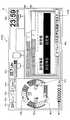
ショベルPSは、表示装置40とは別の独立した表示装置40Sを備えていてもよい。図16は、表示装置40と表示装置40Sを備えたショベルPSのシステム構成図である図16の構成は、表示装置40Sを備える点で、図2Aの構成と異なる。図17は、図16のショベルPSの運転室10内から前方を見たときの図である。The shovel PS may include an
表示装置40Sは、コントローラ30又はコントローラ30に含まれるマシンガイダンス装置50からの指令に応じて各種作業情報を含む画像を表示する。表示装置40Sは、例えば、マシンガイダンス装置50に接続される液晶ディスプレイである。表示装置40Sは、画像表示部41Sに表示する画像を生成する変換処理部40aSを有する。変換処理部40aSは、コントローラ30から表示装置40Sに入力される各種データのうち画像表示部41Sに表示させるデータを画像信号に変換する。そして、変換処理部40aSは、変換した画像信号を画像表示部41Sに出力し、実写画像や各種データに基づいて生成した画像を画像表示部41Sに表示させる。The
表示装置40Sは、入力装置42Sを備える。入力装置42Sは、ショベルPSの操作者がマシンガイダンス装置50を含むコントローラ30に各種情報を入力するための装置である。図16の例では、入力装置42Sは、スイッチパネルに設けられた押しボタンスイッチである。入力装置42は、例えば、メンブレンスイッチであってもよく、タッチパネルであってもよい。The
本実施形態では、表示装置40Sは、図17に示すように、運転室10の床から鉛直上方に延びる取付用ステーに取り付けられている。In the present embodiment, as shown in FIG. 17, the
図16及び図17に示す構成では、表示装置40は、例えば、メイン画面又は情報表示・設定画面等を表示するモニタであってもよい。表示装置40Sは、例えば、マシンガイダンス機能又はマシンコントロール機能等のICTを利用した機能に関する専用モニタであってもよい。但し、表示装置40は、マシンガイダンス機能又はマシンコントロール機能等のICTを利用した機能に関する情報を表示してもよく、表示装置40Sは、メイン画面又は情報表示・設定画面等を表示してもよい。また、図17では、表示装置40Sは運転席DSの左前方に取り付けられているが、運転席DSの右前方に取り付けられていてもよい。In the configurations shown in FIGS. 16 and 17, the
また、図16及び図17に示す構成では、表示装置40Sは、音声入力装置、音声出力装置及びインジケータを備えることで、上記実施形態で実現された機能を実現してもよい。更に、表示装置40Sは、音声入力装置、音声出力装置、インジケータ及びマシンガイダンス装置を備えることで、上記実施形態で実現された機能を実現してもよい。具体的に、表示装置40Sは、ICT設定画面を構成する複数の画面に割り当てられている設定項目の一覧を表示する一覧表41P、音声認識機能の動作状態を表示するステータス表示ウィンドウ41Wを表示させてもよい。Further, in the configurations shown in FIG. 16 and FIG. 17, the
音声入力装置44は、運転室10内に複数設けられていてもよい。音声入力装置44は、図17に示すように、中央音声入力装置44C、左音声入力装置44L及び右音声入力装置44Rを含んでいてもよい。図17の例では、中央音声入力装置44Cは運転席DSの前方に設置され、左音声入力装置44Lは運転席DSの左前方に設置され、右音声入力装置44Rは運転席DSの右前方に設置されている。この構成により、マシンガイダンス装置50は、工事現場等の雑音が大きい場所であっても、運転席DSに着座する操作者が発した音声を確実に認識できる。複数の音声入力装置と協働することで、耐雑音音声認識技術を利用して操作者の音声と雑音とを空間的に区別して操作者の音声を抽出できるためである。その結果、音声の誤認識によるショベルPS等の誤動作を防止できる。A plurality of
また、図17の例では、ショベルPSは、表示装置40に加えて表示装置40Sを備えているが、表示装置40Sを備えることなく、2つ又は3つ以上の画像表示部を含む表示装置40を備えていてもよい。その場合、例えば、1つの画像表示部にメイン画面又は情報表示・設定画面等が表示され、別の1つの画像表示部にマシンガイダンス機能又はマシンコントロール機能等のICTを利用した機能に関する情報が表示されてもよい。Further, in the example of FIG. 17, the shovel PS includes the
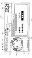
次に、図18を参照し、マシンコントロール機能に関する設定項目が表示されるICT設定画面の別の一例について説明する。図18は、マシンコントロール機能に関する設定項目が表示されるICT設定画面の別の一例であるマシンコントロール設定画面を示す。図18のマシンコントロール設定画面には、ブーム上げ速度、ブーム下げ速度、バケット開き速度、バケット閉じ速度及び目標掘削角度が設定項目として表示されている。図18の例では、マシンコントロール機能は、アーム5の開閉操作が行われたときに、バケット6の先端を目標面に沿って移動させるようにブームシリンダ7、アームシリンダ8及びバケットシリンダ9の少なくとも1つを自動的に伸縮させる機能である。ブームシリンダ7の自動的な伸縮は、ブーム操作の有無及びブーム操作レバーの操作量とは無関係に、ブームシリンダ7を伸縮させることを意味する。アームシリンダ8及びバケットシリンダ9についても同様である。目標面は、例えば、法面又は水平面である。Next, another example of the ICT setting screen on which setting items related to the machine control function are displayed will be described with reference to FIG. FIG. 18 shows a machine control setting screen which is another example of an ICT setting screen on which setting items regarding the machine control function are displayed. In the machine control setting screen of FIG. 18, the boom raising speed, the boom lowering speed, the bucket opening speed, the bucket closing speed and the target digging angle are displayed as setting items. In the example of FIG. 18, the machine control function causes at least the
ブーム上げ速度、ブーム下げ速度、バケット開き速度、バケット閉じ速度及び目標掘削角度は、それぞれ、マシンコントロール機能を実行する際に利用されるパラメータである。図18の例では、ブーム上げ速度は、アーム角度の単位角度当たりのブームシリンダ7の伸長量で表され、ブーム下げ速度は、アーム角度の単位角度当たりのブームシリンダ7の収縮量で表される。また、バケット開き速度は、アーム角度の単位角度当たりのバケットシリンダ9の伸長量で表され、バケット閉じ速度は、アーム角度の単位角度当たりのバケットシリンダ9の収縮量で表される。目標掘削角度は、バケット6の背面と目標面との間に形成される角度で表される。図18の例では、コントローラ30は、マシンコントロール機能の実行中に目標掘削角度が維持されるようにブームシリンダ7、アームシリンダ8及びバケットシリンダ9の少なくとも1つを自動的に伸縮させる。目標掘削角度は、例えば、バケット6の爪先が目標面と接しているときにバケット6の後端部が目標面より上にあるときに正値となり、バケット6の後端部が目標面と接しているときにバケット6の爪先が目標面より上にあるときに負値となる。The boom raising speed, the boom lowering speed, the bucket opening speed, the bucket closing speed, and the target digging angle are respectively parameters used in executing the machine control function. In the example of FIG. 18, the boom raising speed is represented by the extension amount of the
ブーム上げ速度は、典型的には、マシンコントロール機能を利用して形成された実際の掘削面の高さが目標面を下回っている場合にインクリメントされ、目標面を上回っている場合にデクリメントされる。ブーム下げ速度は、典型的には、実際の掘削面の高さが目標面を下回っている場合にデクリメントされ、目標面を上回っている場合にインクリメントされる。バケット開き速度は、典型的には、マシンコントロール機能の実行中におけるバケット6の背面と目標面との間に形成される実際の角度である掘削角度が全体的に目標掘削角度を下回っている場合にインクリメントされ、掘削角度が全体的に目標掘削角度を上回っている場合にデクリメントされる。目標掘削角度は、典型的には、実際の掘削面の凹凸等を考慮して必要に応じて増減される。The boom raising speed is typically incremented when the actual cutting surface height formed using the machine control function is below the target surface, and is decremented when it is above the target surface. . The boom lowering speed is typically decremented when the actual cutting surface height is below the target surface and is incremented when it is above the target surface. If the bucket opening speed is generally below the target digging angle, which is the actual angle formed between the back surface of the
図18のマシンコントロール設定画面は、画像G1~G5を含む。画像G1は、各設定項目をインクリメントする際に利用されるソフトウェアボタン(増加ボタン)であり、画像G1a~G1eを含む。具体的には、画像G1aは、ブーム上げ速度をインクリメントする際に利用される増加ボタンであり、画像G1bは、ブーム下げ速度をインクリメントする際に利用される増加ボタンであり、画像G1cは、バケット開き速度をインクリメントする際に利用される増加ボタンであり、画像G1dは、バケット閉じ速度をインクリメントする際に利用される増加ボタンであり、画像G1eは、目標掘削角度をインクリメントする際に利用される増加ボタンである。画像G2は、各設定項目をデクリメントする際に利用されるソフトウェアボタン(減少ボタン)であり、画像G2a~G2eを含む。具体的には、画像G2aは、ブーム上げ速度をデクリメントする際に利用される減少ボタンであり、画像G2bは、ブーム下げ速度をデクリメントする際に利用される減少ボタンであり、画像G2cは、バケット開き速度をデクリメントする際に利用される減少ボタンであり、画像G2dは、バケット閉じ速度をデクリメントする際に利用される減少ボタンであり、画像G2eは、目標掘削角度をデクリメントする際に利用される減少ボタンである。図18の例では、各設定項目は、9段階の調節ができるように構成されている。具体的には、プラス側に4段階で、且つ、マイナス側に4段階の調節ができるように構成されている。The machine control setting screen of FIG. 18 includes images G1 to G5. The image G1 is a software button (increasing button) used when incrementing each setting item, and includes images G1a to G1e. Specifically, the image G1a is an increase button used when incrementing the boom raising speed, the image G1b is an increase button used when incrementing the boom lowering speed, and the image G1c is a bucket The increase button used when incrementing the opening speed, the image G1d is the increase button used when incrementing the bucket closing speed, and the image G1e is used when incrementing the target digging angle It is an increase button. The image G2 is a software button (decrease button) used when decrementing each setting item, and includes images G2a to G2e. Specifically, the image G2a is a reduction button used when decrementing the boom raising speed, the image G2b is a reduction button used when decrementing the boom lowering speed, and the image G2c is a bucket The reduction button used when decrementing the opening speed, the image G2d is the reduction button used when decrementing the bucket closing speed, and the image G2e is used when decrementing the target digging angle It is a decrease button. In the example of FIG. 18, each setting item is configured to be able to be adjusted in nine steps. Specifically, it is configured to be able to perform adjustment in four steps on the plus side and in four steps on the minus side.
画像G3は、増加ボタン及び減少ボタンの少なくとも1つを用いて行われた各設定項目の調整結果の全てを有効にするためのソフトウェアボタン(適用ボタン)である。The image G3 is a software button (application button) for validating all the adjustment results of each setting item performed using at least one of the increase button and the decrease button.
画像G4は、増加ボタン及び減少ボタンの少なくとも1つを用いて行われた各設定項目の調整結果の全てをリセットするためのソフトウェアボタン(リセットボタン)である。The image G4 is a software button (reset button) for resetting all adjustment results of each setting item performed using at least one of the increase button and the decrease button.
画像G5は、前回の適用ボタンの押下の後に増加ボタン及び減少ボタンの少なくとも1つを用いて行われた各設定項目の調節結果をキャンセルするためのソフトウェアボタン(キャンセルボタン)である。The image G5 is a software button (cancel button) for canceling the adjustment result of each setting item performed using at least one of the increase button and the decrease button after the previous pressing of the application button.
マシンコントロール設定画面は、「旋回時ブーム上げ速度」を設定項目として含んでいてもよい。旋回時ブーム上げ速度は、マシンコントロール機能のうちの別の1つである第1支援機能の際に利用される。第1支援機能は、旋回操作とブーム上げ操作とを含む複合操作が行われたときに、上部旋回体3の旋回速度に応じてブーム4の上げ速度を調節するようにブームシリンダ7を自動的に伸縮させる機能である。旋回時ブーム上げ速度は、例えば、旋回角度の単位角度当たりのブームシリンダ7の伸長量で表される。The machine control setting screen may include “turning boom raising speed” as a setting item. The pivoting boom raising speed is used in the first support function, which is another one of the machine control functions. The first support function automatically controls the
マシンコントロール設定画面は、「旋回時ブーム下げ速度」を設定項目として含んでいてもよい。旋回時ブーム下げ速度は、マシンコントロール機能のうちの別の1つである第2支援機能の際に利用される。第2支援機能は、旋回操作とブーム下げ操作とを含む複合操作が行われたときに、上部旋回体3の旋回速度に応じてブーム4の下げ速度を調節するようにブームシリンダ7を自動的に伸縮させる機能である。旋回時ブーム下げ速度は、例えば、旋回角度の単位角度当たりのブームシリンダ7の収縮量で表される。The machine control setting screen may include “turning boom lowering speed” as a setting item. The pivoting boom lowering speed is used in a second support function, which is another one of the machine control functions. The second support function automatically adjusts the
マシンコントロール設定画面は、「ブーム上げ時旋回速度」を設定項目として含んでいてもよい。ブーム上げ時旋回速度は、マシンコントロール機能のうちの更に別の1つである第3支援機能の際に利用される。第3支援機能は、旋回操作とブーム上げ操作とを含む複合操作が行われたときに、ブーム4の上げ速度に応じて旋回速度を調節するように旋回用油圧モータを自動的に回転させる機能である。ブーム上げ時旋回速度は、例えば、ブームシリンダ7の単位伸長量当たりの旋回用油圧モータの回転角度で表される。The machine control setting screen may include “boom raising turning speed” as a setting item. The boom raising pivoting speed is used in the third support function, which is another one of the machine control functions. The third support function is a function to automatically rotate the turning hydraulic motor so as to adjust the turning speed according to the raising speed of the
マシンコントロール設定画面は、「ブーム下げ時旋回速度」を設定項目として含んでいてもよい。ブーム下げ時旋回速度は、マシンコントロール機能のうちの更に別の1つである第4支援機能の際に利用される。第4支援機能は、旋回操作とブーム下げ操作とを含む複合操作が行われたときに、ブーム4の下げ速度に応じて旋回速度を調節するように旋回用油圧モータを自動的に回転させる機能である。ブーム下げ時旋回速度は、例えば、ブームシリンダ7の単位伸長量当たりの旋回用油圧モータの回転角度で表される。The machine control setting screen may include “boom lowering pivoting speed” as a setting item. The boom lowering pivoting speed is used in the fourth support function, which is another one of the machine control functions. The fourth support function is a function to automatically rotate the turning hydraulic motor so as to adjust the turning speed according to the lowering speed of the
この構成により、ショベルPSの操作者は、入力装置42及び音声入力装置44の少なくとも1つを利用してマシンコントロール設定画面における各設定項目を設定できる。すなわち、操作者は、マシンガイダンス装置50を手動で操作することに加え、マシンガイダンス装置50に音声指令を与えることによっても、マシンコントロール設定画面における各設定項目を設定できる。With this configuration, the operator of the shovel PS can set each setting item on the machine control setting screen using at least one of the
本願は、2017年8月14日に出願した日本国特許出願2017-156652号に基づく優先権を主張するものであり、この日本国特許出願の全内容を本願に参照により援用する。The present application claims priority based on Japanese Patent Application No. 2017-156652 filed on Aug. 14, 2017, the entire content of which is incorporated herein by reference.
1・・・下部走行体 2・・・旋回機構 3・・・上部旋回体 4・・・ブーム 5・・・アーム 6・・・バケット 7・・・ブームシリンダ 8・・・アームシリンダ 9・・・バケットシリンダ 10・・・運転室 11・・・エンジン 11a・・・オルタネータ 11b・・・スタータ 11c・・・水温センサ 14・・・メインポンプ 14a・・・レギュレータ 14b・・・吐出圧力センサ 14c・・・油温センサ 15・・・パイロットポンプ 15a、15b・・・圧力センサ 17・・・コントロールバルブ 26・・・操作装置 26S・・・スイッチボタン 30・・・コントローラ 30a・・・記憶部 40・・・表示装置 40a・・・変換処理部 41・・・画像表示部 41P・・・一覧表 41V・・・メイン画面 41VC・・・情報表示・設定画面 41W・・・ステータス表示ウィンドウ 42・・・入力装置 42a・・・表示切換ボタン 42b・・・方向ボタン 43・・・音声出力装置 44・・・音声入力装置 47・・・記憶装置 49・・・ゲートロックレバー 49a・・・ゲートロック弁 50・・・マシンガイダンス装置 60・・・インジケータ 70・・・蓄電池 72・・・電装品 74・・・エンジンコントローラ 75・・・エンジン回転数調整ダイヤル 80・・・撮像装置 80B・・・バックカメラ 80L・・・左カメラ 80R・・・右カメラ 501・・・傾斜角算出部 502・・・高さ算出部 503・・・距離算出部 504・・・目標設定部 505・・・音声認識部 506・・・音声操作部 DS・・・運転席 D1・・・GPS装置 PS・・・ショベル S1・・・ブーム角度センサ S2・・・アーム角度センサ S3・・・バケット角度センサ S4・・・車体傾斜センサ T1・・・通信装置1 ... lower traveling
Claims (13)
Translated fromJapanese前記下部走行体に旋回自在に搭載された上部旋回体と、
前記上部旋回体に搭載された運転室と、
前記運転室内に設けられた表示装置と、
前記運転室内に設けられた音声入力装置と、
音声認識機能を備えた制御装置と、を有し、
前記表示装置は、施工支援に関する設定画面を表示し、
前記制御装置は、前記音声入力装置を通じて入力された音声を認識し、認識結果に応じて前記設定画面に関する処理を実行する、
ショベル。The lower traveling body,
An upper swing body rotatably mounted on the lower traveling body;
A cab mounted on the upper revolving superstructure;
A display device provided in the driver's cab;
A voice input device provided in the driver's cabin;
A controller having a voice recognition function;
The display device displays a setting screen regarding construction support,
The control device recognizes a voice input through the voice input device, and executes processing relating to the setting screen according to the recognition result.
Excavator.
前記下部走行体に旋回自在に搭載された上部旋回体と、
前記上部旋回体に搭載された運転室と、
前記運転室内に設けられた表示装置と、
前記運転室内に設けられた音声入力装置と、
音声認識機能を備えた制御装置と、を有し、
前記制御装置は、前記音声入力装置を通じて入力された音声を認識し、認識結果に応じて音声操作部を起動させる、
ショベル。The lower traveling body,
An upper swing body rotatably mounted on the lower traveling body;
A cab mounted on the upper revolving superstructure;
A display device provided in the driver's cab;
A voice input device provided in the driver's cabin;
A controller having a voice recognition function;
The control device recognizes voice input through the voice input device, and activates a voice operation unit according to the recognition result.
Excavator.
請求項2に記載のショベル。The control device displays a setting screen regarding construction support on the display device according to the recognition result.
The shovel according to claim 2.
請求項1に記載のショベル。The control device inputs values of setting items on the setting screen according to the recognition result.
The shovel according to claim 1.
請求項1に記載のショベル。The control device collectively inputs values of a plurality of setting items on the setting screen according to the recognition result.
The shovel according to claim 1.
請求項1に記載のショベル。It has an input device for manually inputting the values of setting items on the setting screen,
The shovel according to claim 1.
請求項1に記載のショベル。It has an audio output device that outputs an audio related to the recognition result.
The shovel according to claim 1.
請求項1に記載のショベル。The display device is composed of a plurality of display devices.
The shovel according to claim 1.
請求項1に記載のショベル。The display device displays a status display window,
The shovel according to claim 1.
請求項1に記載のショベル。Further comprising an indicator,
The shovel according to claim 1.
請求項1に記載のショベル。The voice input device is composed of a plurality of voice input devices.
The shovel according to claim 1.
前記下部走行体に旋回自在に搭載された上部旋回体と、
前記上部旋回体に搭載された運転室と、
前記運転室内に設けられた表示装置と、
制御装置と、を有し、
前記表示装置は、情報通信技術を利用した施工支援に関する設定画面を表示し、
前記制御装置は、携帯端末の音声入力装置を通じて入力された音声の認識結果に応じて前記設定画面に関する処理を実行する、
ショベル。The lower traveling body,
An upper swing body rotatably mounted on the lower traveling body;
A cab mounted on the upper revolving superstructure;
A display device provided in the driver's cab;
And a controller.
The display device displays a setting screen regarding construction support using information communication technology,
The control device executes processing relating to the setting screen according to a recognition result of voice input through a voice input device of a portable terminal.
Excavator.
前記音声入力装置と、
前記音声入力装置を通じて入力された音声又は該音声の認識結果をショベルに送信する通信装置と、を有する、
支援装置。A lower traveling unit, an upper revolving unit pivotally mounted on the lower traveling unit, a driver's cab mounted on the upper revolving unit, and a display device provided in the operator's cab and displaying a setting screen regarding construction support A support device cooperating with a shovel, comprising: a communication device; and a control device that executes processing related to the setting screen according to a recognition result of voice input through the voice input device,
The voice input device;
And a communication device for transmitting the voice input through the voice input device or the recognition result of the voice to the shovel.
Support device.
Priority Applications (5)
| Application Number | Priority Date | Filing Date | Title |
|---|---|---|---|
| CN201880020613.8ACN110462142A (en) | 2017-08-14 | 2018-08-10 | Excavators and supporting devices working in conjunction with excavators |
| EP18845548.9AEP3670764A4 (en) | 2017-08-14 | 2018-08-10 | SHOVEL AND SUPPORT DEVICE WORKING WITH THE SHOVEL |
| JP2019536762AJP7344117B2 (en) | 2017-08-14 | 2018-08-10 | Excavators and support devices that work with the excavators |
| KR1020197028667AKR102559166B1 (en) | 2017-08-14 | 2018-08-10 | A shovel and a support device cooperating with the shovel |
| US16/783,336US11566401B2 (en) | 2017-08-14 | 2020-02-06 | Shovel and assist device to work together with shovel |
Applications Claiming Priority (2)
| Application Number | Priority Date | Filing Date | Title |
|---|---|---|---|
| JP2017-156652 | 2017-08-14 | ||
| JP2017156652 | 2017-08-14 |
Related Child Applications (1)
| Application Number | Title | Priority Date | Filing Date |
|---|---|---|---|
| US16/783,336ContinuationUS11566401B2 (en) | 2017-08-14 | 2020-02-06 | Shovel and assist device to work together with shovel |
Publications (1)
| Publication Number | Publication Date |
|---|---|
| WO2019035427A1true WO2019035427A1 (en) | 2019-02-21 |
Family
ID=65361838
Family Applications (1)
| Application Number | Title | Priority Date | Filing Date |
|---|---|---|---|
| PCT/JP2018/030107CeasedWO2019035427A1 (en) | 2017-08-14 | 2018-08-10 | Shovel and supporting device cooperating with shovel |
Country Status (6)
| Country | Link |
|---|---|
| US (1) | US11566401B2 (en) |
| EP (1) | EP3670764A4 (en) |
| JP (1) | JP7344117B2 (en) |
| KR (1) | KR102559166B1 (en) |
| CN (1) | CN110462142A (en) |
| WO (1) | WO2019035427A1 (en) |
Cited By (7)
| Publication number | Priority date | Publication date | Assignee | Title |
|---|---|---|---|---|
| JP2020185618A (en)* | 2019-05-10 | 2020-11-19 | 株式会社スター精機 | Machine operation method, machine operation setting method, and machine operation confirmation method |
| EP3769600A1 (en)* | 2019-07-22 | 2021-01-27 | CLAAS E-Systems GmbH | Agricultural machine |
| WO2022014146A1 (en)* | 2020-07-16 | 2022-01-20 | 株式会社クボタ | Work vehicle specification change system, work vehicle specification change method, and work vehicle specification change program |
| JP2022157410A (en)* | 2021-03-31 | 2022-10-14 | 住友建機株式会社 | working machine |
| US20240209597A1 (en)* | 2022-12-21 | 2024-06-27 | Sumitomo Heavy Industries, Ltd. | Shovel management system and shovel management apparatus |
| WO2024247625A1 (en)* | 2023-05-30 | 2024-12-05 | 株式会社Screenホールディングス | Work assistance method and work assistance system |
| WO2025088927A1 (en)* | 2023-10-23 | 2025-05-01 | コベルコ建機株式会社 | Work information setting system, work information setting program, and work information setting method |
Families Citing this family (1)
| Publication number | Priority date | Publication date | Assignee | Title |
|---|---|---|---|---|
| JP7418076B2 (en)* | 2019-07-16 | 2024-01-19 | キヤノン株式会社 | Information processing system, information processing device, information processing method |
Citations (9)
| Publication number | Priority date | Publication date | Assignee | Title |
|---|---|---|---|---|
| JP2002023791A (en)* | 2000-07-06 | 2002-01-25 | Shin Caterpillar Mitsubishi Ltd | Speech recognition system on construction equipment |
| JP2004027830A (en)* | 1996-06-05 | 2004-01-29 | Topcon Corp | Excavator |
| JP2005004032A (en)* | 2003-06-13 | 2005-01-06 | Sony Corp | Device and method for speech recognition |
| JP2006018780A (en)* | 2004-07-05 | 2006-01-19 | Nec Electronics Corp | Item selection device and program |
| WO2012165657A1 (en)* | 2011-06-03 | 2012-12-06 | 日本電気株式会社 | Speech processing system, speech processing device, speech processing method, and program therefor |
| WO2014013910A1 (en)* | 2012-07-19 | 2014-01-23 | 住友建機株式会社 | Excavator |
| WO2015163381A1 (en) | 2014-04-25 | 2015-10-29 | 住友建機株式会社 | Construction machine |
| WO2016098741A1 (en) | 2014-12-16 | 2016-06-23 | 住友建機株式会社 | Shovel and shovel control method |
| JP2017156652A (en) | 2016-03-04 | 2017-09-07 | 東洋インキScホールディングス株式会社 | Colored composition for color filter and color filter |
Family Cites Families (22)
| Publication number | Priority date | Publication date | Assignee | Title |
|---|---|---|---|---|
| JP2000163091A (en)* | 1998-11-27 | 2000-06-16 | Denso Corp | Speech recognition device |
| JP2002021121A (en) | 2000-07-07 | 2002-01-23 | Shin Caterpillar Mitsubishi Ltd | Operation lever allocating method for construction machine |
| JP2002030696A (en) | 2000-07-18 | 2002-01-31 | Shin Caterpillar Mitsubishi Ltd | Voice interlocking operation device and voice interlocking operation method in construction machine |
| JP3676204B2 (en) | 2000-07-18 | 2005-07-27 | 新キャタピラー三菱株式会社 | Voice attachment control method for construction machinery |
| JP2002049403A (en)* | 2000-08-07 | 2002-02-15 | Shin Caterpillar Mitsubishi Ltd | Voice operated controller for construction equipment |
| DE10063901A1 (en)* | 2000-12-21 | 2002-07-04 | Deere & Co | operating device |
| JP2004001987A (en)* | 2002-03-25 | 2004-01-08 | Hitachi Constr Mach Co Ltd | Operation support device |
| JP4506286B2 (en)* | 2003-08-19 | 2010-07-21 | 株式会社小松製作所 | Construction machinery |
| US7949529B2 (en)* | 2005-08-29 | 2011-05-24 | Voicebox Technologies, Inc. | Mobile systems and methods of supporting natural language human-machine interactions |
| JP2007120384A (en)* | 2005-10-27 | 2007-05-17 | Kobelco Contstruction Machinery Ltd | Hybrid type construction machine |
| ATE526801T1 (en)* | 2006-01-11 | 2011-10-15 | Qualcomm Inc | COMMUNICATION METHOD AND APPARATUS FOR SENDING PRIORITY INFORMATION VIA BEACON SIGNALS |
| JP5836362B2 (en)* | 2011-03-08 | 2015-12-24 | 住友建機株式会社 | Excavator and control method of excavator |
| JP5683345B2 (en)* | 2011-03-25 | 2015-03-11 | 五洋建設株式会社 | Construction work guidance management system |
| CN104954596B (en)* | 2011-07-25 | 2018-03-30 | 株式会社久保田 | The setting altering system of working rig and working rig |
| US9598836B2 (en)* | 2012-03-29 | 2017-03-21 | Harnischfeger Technologies, Inc. | Overhead view system for a shovel |
| JP6312053B2 (en)* | 2013-09-06 | 2018-04-18 | 株式会社ユピテル | System and program |
| WO2015163382A1 (en)* | 2014-04-25 | 2015-10-29 | 住友建機株式会社 | Construction machine and method for controlling construction machine |
| EP3111738B1 (en)* | 2015-07-01 | 2018-09-19 | Kverneland Group Mechatronics BV | Method for controlling operation of an agricultural machine and system |
| US9500490B1 (en)* | 2015-07-31 | 2016-11-22 | Komatsu America Corp. | Speed control display system and method |
| WO2016013686A1 (en)* | 2015-07-31 | 2016-01-28 | 株式会社小松製作所 | Display system for work machine, display device for work machine, and display method for work machine |
| US9803337B2 (en)* | 2016-02-16 | 2017-10-31 | Caterpillar Inc. | System and method for in-pit crushing and conveying operations |
| CN107076555B (en)* | 2016-09-30 | 2020-06-16 | 株式会社小松制作所 | Display system for work machine and work machine |
- 2018
- 2018-08-10WOPCT/JP2018/030107patent/WO2019035427A1/ennot_activeCeased
- 2018-08-10JPJP2019536762Apatent/JP7344117B2/enactiveActive
- 2018-08-10KRKR1020197028667Apatent/KR102559166B1/enactiveActive
- 2018-08-10EPEP18845548.9Apatent/EP3670764A4/enactivePending
- 2018-08-10CNCN201880020613.8Apatent/CN110462142A/enactivePending
- 2020
- 2020-02-06USUS16/783,336patent/US11566401B2/enactiveActive
Patent Citations (9)
| Publication number | Priority date | Publication date | Assignee | Title |
|---|---|---|---|---|
| JP2004027830A (en)* | 1996-06-05 | 2004-01-29 | Topcon Corp | Excavator |
| JP2002023791A (en)* | 2000-07-06 | 2002-01-25 | Shin Caterpillar Mitsubishi Ltd | Speech recognition system on construction equipment |
| JP2005004032A (en)* | 2003-06-13 | 2005-01-06 | Sony Corp | Device and method for speech recognition |
| JP2006018780A (en)* | 2004-07-05 | 2006-01-19 | Nec Electronics Corp | Item selection device and program |
| WO2012165657A1 (en)* | 2011-06-03 | 2012-12-06 | 日本電気株式会社 | Speech processing system, speech processing device, speech processing method, and program therefor |
| WO2014013910A1 (en)* | 2012-07-19 | 2014-01-23 | 住友建機株式会社 | Excavator |
| WO2015163381A1 (en) | 2014-04-25 | 2015-10-29 | 住友建機株式会社 | Construction machine |
| WO2016098741A1 (en) | 2014-12-16 | 2016-06-23 | 住友建機株式会社 | Shovel and shovel control method |
| JP2017156652A (en) | 2016-03-04 | 2017-09-07 | 東洋インキScホールディングス株式会社 | Colored composition for color filter and color filter |
Cited By (8)
| Publication number | Priority date | Publication date | Assignee | Title |
|---|---|---|---|---|
| JP2020185618A (en)* | 2019-05-10 | 2020-11-19 | 株式会社スター精機 | Machine operation method, machine operation setting method, and machine operation confirmation method |
| EP3769600A1 (en)* | 2019-07-22 | 2021-01-27 | CLAAS E-Systems GmbH | Agricultural machine |
| WO2022014146A1 (en)* | 2020-07-16 | 2022-01-20 | 株式会社クボタ | Work vehicle specification change system, work vehicle specification change method, and work vehicle specification change program |
| US12336446B2 (en) | 2020-07-16 | 2025-06-24 | Kubota Corporation | Work vehicle specification change system, work vehicle specification change method, and work vehicle specification change program |
| JP2022157410A (en)* | 2021-03-31 | 2022-10-14 | 住友建機株式会社 | working machine |
| US20240209597A1 (en)* | 2022-12-21 | 2024-06-27 | Sumitomo Heavy Industries, Ltd. | Shovel management system and shovel management apparatus |
| WO2024247625A1 (en)* | 2023-05-30 | 2024-12-05 | 株式会社Screenホールディングス | Work assistance method and work assistance system |
| WO2025088927A1 (en)* | 2023-10-23 | 2025-05-01 | コベルコ建機株式会社 | Work information setting system, work information setting program, and work information setting method |
Also Published As
| Publication number | Publication date |
|---|---|
| US20200173149A1 (en) | 2020-06-04 |
| JPWO2019035427A1 (en) | 2020-11-19 |
| KR102559166B1 (en) | 2023-07-24 |
| EP3670764A4 (en) | 2020-08-26 |
| JP7344117B2 (en) | 2023-09-13 |
| CN110462142A (en) | 2019-11-15 |
| EP3670764A1 (en) | 2020-06-24 |
| KR20200040695A (en) | 2020-04-20 |
| US11566401B2 (en) | 2023-01-31 |
Similar Documents
| Publication | Publication Date | Title |
|---|---|---|
| JP7344117B2 (en) | Excavators and support devices that work with the excavators | |
| JP7330107B2 (en) | Excavator and excavator management system | |
| JP7522552B2 (en) | Excavator | |
| CN111315935B (en) | Excavator | |
| JP6615473B2 (en) | Excavator | |
| JP6965160B2 (en) | Excavator | |
| US11519158B2 (en) | Shovel | |
| JP2017110472A (en) | Shovel | |
| CN113631779A (en) | Excavators and Construction Systems | |
| JP7474192B2 (en) | Excavator | |
| JP7275108B2 (en) | Excavator | |
| WO2018062363A1 (en) | Shovel | |
| JP7413357B2 (en) | Excavators and construction systems | |
| EP4394133A1 (en) | Excavator, and excavator operation system | |
| WO2019181923A1 (en) | Assistance device for construction machines | |
| EP4461879A1 (en) | Excavator | |
| JP2021181732A (en) | Excavator | |
| JP2019007308A (en) | Shovel, and, management device and support device for shovel | |
| US20250215667A1 (en) | Excavator and excavator control system | |
| US20250283307A1 (en) | Work machine and control system for work machine | |
| US20250137235A1 (en) | Excavator and excavator operation control system | |
| JP2025033735A (en) | Work Machine | |
| JP2024082696A (en) | Shovel, operation assistance method and operation assistance program | |
| JP2024089387A (en) | Excavator management system, excavator management device | |
| JP2025091078A (en) | Shovel and shovel control device |
Legal Events
| Date | Code | Title | Description |
|---|---|---|---|
| 121 | Ep: the epo has been informed by wipo that ep was designated in this application | Ref document number:18845548 Country of ref document:EP Kind code of ref document:A1 | |
| ENP | Entry into the national phase | Ref document number:2019536762 Country of ref document:JP Kind code of ref document:A | |
| NENP | Non-entry into the national phase | Ref country code:DE | |
| ENP | Entry into the national phase | Ref document number:2018845548 Country of ref document:EP Effective date:20200316 |