WO2019035206A1 - Medical system and image generation method - Google Patents
Medical system and image generation methodDownload PDFInfo
- Publication number
- WO2019035206A1 WO2019035206A1PCT/JP2017/029614JP2017029614WWO2019035206A1WO 2019035206 A1WO2019035206 A1WO 2019035206A1JP 2017029614 WJP2017029614 WJP 2017029614WWO 2019035206 A1WO2019035206 A1WO 2019035206A1
- Authority
- WO
- WIPO (PCT)
- Prior art keywords
- image
- display image
- virtual image
- medical device
- display
- Prior art date
- Legal status (The legal status is an assumption and is not a legal conclusion. Google has not performed a legal analysis and makes no representation as to the accuracy of the status listed.)
- Ceased
Links
Images


Classifications
- A—HUMAN NECESSITIES
- A61—MEDICAL OR VETERINARY SCIENCE; HYGIENE
- A61B—DIAGNOSIS; SURGERY; IDENTIFICATION
- A61B1/00—Instruments for performing medical examinations of the interior of cavities or tubes of the body by visual or photographical inspection, e.g. endoscopes; Illuminating arrangements therefor
- A61B1/04—Instruments for performing medical examinations of the interior of cavities or tubes of the body by visual or photographical inspection, e.g. endoscopes; Illuminating arrangements therefor combined with photographic or television appliances
- A61B1/045—Control thereof
Definitions
- the present inventionrelates to a medical system and an image generation method using the medical system.
- the appropriate type of medical deviceis selected in accordance with the procedure, and the selected medical device is inserted into the abdominal cavity.
- the operatorneeds to select a mesh with the optimal size necessary and sufficient to close the hernia gate, and insert the selected mesh into the abdominal cavity is there.
- the operatorconfirms the image captured by the endoscope, estimates the length and area of the contour of the tissue in the three-dimensional space, and selects a mesh of an optimal size. If the selected mesh is inserted into the abdominal cavity and the size of the mesh is found to be small relative to the hernia gate, the operator needs to remove the mesh from the abdominal cavity and reinsert the reselected mesh into the abdominal cavity . Depending on the experience and technique of the operator, there is a problem that it takes time for trial and error of mesh selection.
- Patent Document 1describes a telesurgery robot system capable of measuring the length and area of a contour of a tissue in a three-dimensional space from an endoscopic image of the tissue acquired by the endoscope.
- the telesurgical robot systemcan measure, for example, the distance between measurement points designated by a treatment tool, and superimpose the measured distance information on an endoscopic image for display.
- the operator who uses the telesurgical robot systemcan grasp the dimensions and the like in the three-dimensional space of the tissue shown in the endoscopic image.
- Patent Document 1requires procedures such as designation of measurement points in order to perform measurement in a three-dimensional space, and it is possible to rapidly measure dimensions etc. in the three-dimensional space. It was not. In addition, it has been difficult for the operator to intuitively determine the most appropriate type of medical device from the measurement results of dimensions and the like in the three-dimensional space.
- the present inventionaims to provide a medical system capable of supporting selection of an appropriate type of medical device and an image generation method using the medical system.
- a medical systemincludes a treatment tool, an endoscope having an imaging unit, a control device that generates a display image from a captured image acquired by the imaging unit, a display device that displays the display image, and medical treatment
- An input device for selecting a devicethe control device measures a relative position from the endoscope to the treatment tool, and the control device reflects the display image based on the relative position
- a virtual image of the medical device at a relative position to the treatment tool and having a relative sizeis superimposed on the display image.
- the image generation methodis a medical system in which a display image is generated from a captured image acquired by an imaging unit of an endoscope, and a medical device selecting step of selecting a medical device using an input device;
- the medical devicehaving a relative size relative to the treatment tool shown in the display image based on the relative position measuring step of measuring the relative position to the treatment tool and the relative position And a virtual image superimposing step of superimposing the virtual image on the display image.
- selection of an appropriate type of medical devicecan be assisted.
- the display image on which the virtual image of the selected mesh A is superimposedis shown.
- the display image on which the virtual image of the selected mesh B is superimposedis shown.
- the display image on which the virtual image of the selected stapler A is superimposedis shown.
- the display image on which the virtual image of the selected stapler B is superimposedis shown. It is a figure which shows the whole structure of the modification of the medical system. It is a figure which shows the whole structure of the modification of the medical system.
- the endoscope of the medical system concerning a third embodiment of the present inventionis shown. In the medical system, the display image on which the virtual image of the selected snare A is superimposed is shown. In the medical system, the display image on which the virtual image of the selected snare B is superimposed is shown.
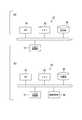
- FIG. 1is a diagram showing an entire configuration of a medical system 100 according to the present embodiment.
- the medical system 100includes a treatment tool 1, an endoscope 2, a control device 3, a display device 4, and an input device 5.
- the medical system 100is a system that supports a treatment to be performed by inserting the treatment instrument 1 or the endoscope 2 or the like from separate holes (openings) opened in an abdominal wall in laparoscopic surgery.
- the treatment tool 1has an elongated insertion portion 10 that can be inserted into the abdominal cavity of a patient, and an operation portion 11 provided on the proximal end side of the insertion portion 10.
- the operatorpasses the insertion portion 10 through the trocar T which is punctured in the abdomen B of the patient and introduces the insertion portion 10 into the abdominal cavity.
- the operatormay introduce a plurality of treatment tools 1 into the abdominal cavity.
- the insertion portion 10has a treatment portion 12 at the tip end for treating an affected area of a patient.
- the treatment unit 12is a gripping mechanism configured by a pair of gripping members 12 a.
- the operation unit 11is a member for operating the pair of gripping members 12a.
- the operation unit 11has a handle, and moves the handle relative to the other portion of the operation unit 11 to open and close the pair of holding members 12 a of the treatment unit 12.
- the operatorcan operate the treatment unit 12 by holding the operation unit 11 with one hand.
- FIG. 2is a hardware configuration diagram of the medical system 100 excluding the treatment tool 1.
- the endoscope 2has an elongated rigid insertion portion 20 which can be inserted into the abdominal cavity of a patient, and a handle portion 21.
- the operatorpasses the insertion portion 20 through the trocar T which is punctured in the abdomen B of the patient and introduces the insertion portion 20 into the abdominal cavity.
- the insertion unit 20is provided at the tip thereof with an imaging unit 22 having a lens for imaging a situation in the abdomen of a patient and an imaging element.
- the insertion unit 20 introduced into the abdominal cavityis disposed at a position where the imaging unit 22 can photograph an affected area in the abdomen that is a treatment target.
- the imaging unit 22may have an optical zoom or electronic zoom function.
- the operatorcan change the position and the orientation of the imaging unit 22 of the endoscope 2 by holding the holding unit 21 and moving the endoscope 2.
- the insertion portion 20may further include an active bending portion that actively bends. By bending the active bending portion provided in a part of the insertion portion 20, the position and the orientation of the imaging unit 22 can be changed.
- a control signal line for controlling the imaging unit 22, a transmission signal for transferring a captured image captured by the imaging unit 22, and the likeare wired inside the hand holding unit 21.
- the control device 3has a control unit 33, as shown in FIG.
- the control device 3receives the captured image captured by the imaging unit 22 of the endoscope 2 and transfers it to the display device 4 as a display image.
- the control unit 33is configured by a device (computer) provided with hardware capable of executing programs such as a CPU (Central Processing Unit) and a memory.
- the function of the control unit 33can be realized as a function of software by the control unit 33 reading and executing a program for controlling the CPU.
- at least a part of the control unit 33may be configured by a dedicated logic circuit or the like.
- the same functioncan be realized by connecting at least a part of hardware configuring the control unit 33 with a communication line.
- FIG. 3Ashows an example of the overall configuration of the control unit 33.
- the control unit 33includes a CPU 34, a memory 35 capable of reading a program, a storage unit 36, and an input / output control unit 37.
- a program provided to the control unit 33 for controlling the operation of the control unit 33is read into the memory 35 and executed by the CPU 34.
- the storage unit 36is a non-volatile storage medium storing the above-described program and necessary data.
- the storage unit 36is configured of, for example, a ROM, a hard disk or the like.
- the program recorded in the storage unit 36is read into the memory 35 and executed by the CPU 34.
- the storage unit 36executes, for example, virtual images or virtual images of “types” of medical devices introduced into the abdominal cavity, such as forceps, electric scalpel, stapler, snare, mesh, etc., and “types” of medical devices. And shape data for virtual image that can be generated. Further, with regard to medical devices having variations in size, virtual image shape data capable of generating a virtual image for each “size” or a virtual image for each “size” is also stored in the storage unit 36. In the following description, virtual image or virtual image shape data is referred to as "virtual image data", and virtual image data for each "type" and "size” of a medical device is referred to as "medical device information”. Name.
- the input / output control unit 37receives input data from the endoscope 2 and transfers the input data to the CPU 34 or the like.
- the input / output control unit 37also generates data, control signals, and the like for the endoscope 2 and the display device 4 based on an instruction of the CPU 34.
- the control unit 33receives a captured image as input data from the endoscope 2 and reads the captured image into the memory 35. Based on the program read into the memory 35, the CPU 34 performs image processing on the captured image. The captured image subjected to the image processing is transferred to the display device 4 as a display image.
- the control unit 33has at least two types of image processing operation modes of a normal mode and a virtual image superposition mode.
- the operating modeis controlled by the program.
- the control unit 33 operating in the normal modeperforms image processing such as image format conversion, contrast adjustment, and resizing processing on the captured image to generate a display image.
- the control unit 33 operating in the virtual image superposition modeperforms an image processing of superimposing a virtual image of a medical device described later on a display image.
- control unit 33is not limited to the device provided in one piece of hardware.
- the control unit 33is configured by separating the CPU 34, the memory 35, the storage unit 36, and the input / output control unit 37 as separate pieces of hardware, and then connecting the hardware through a communication line. You may Alternatively, the control unit 33 may realize the control unit 33 as a cloud system by separating the storage unit 36 and similarly connecting through the communication line.
- the control unit 33is other than the CPU 34, the memory 35, the storage unit 36, and the input / output control unit 37 shown in FIG. 3A, and further, those necessary to control the operation of the control device 3 are further included. You may have.
- the control unit 33may further include an image operation unit 38 that performs part or all of the image processing and image recognition processing performed by the CPU 34.
- the control unit 33can execute specific image processing and image recognition processing at high speed. Further, it may further include an image transfer unit for transferring the display image from the memory 35 to the display device 4.
- the display device 4is a device that displays the display image transferred by the control device 3.
- the display device 4has a known monitor 41 such as an LCD display.
- the display device 4may have a plurality of monitors 41.
- the display device 4may include a head mounted display or a projector instead of the monitor 41.
- the monitor 41can also display a GUI (Graphical User Interface) image generated by the control device 3 as a GUI.
- GUIGraphic User Interface
- the monitor 41can display a control information display of the medical system 100 and an alert display on the GUI for the operator.
- the display device 4can also display a message prompting the user to input information from the input device 5 or a GUI display necessary for the information input.
- the input device 5is a device by which an operator inputs an instruction or the like to the control unit 33.
- the input device 5has an input unit 51 as shown in FIG.
- the input unit 51is a device that selects an operation mode of image processing of the control unit 33, and selects a medical device to be superimposed and displayed as a virtual image on a display image.
- the input unit 51may be configured by a switch or may be configured by a touch panel.
- the touch panelmay be integrated with the monitor 41.
- the input unit 51may be configured by a keyboard or a mouse.
- the control unit 33displays a list of operation modes and a list of medical devices on the monitor 41 as a GUI, and from the list displayed on the monitor 41, the operator inputs desired operation modes and operation of medical devices to the keyboard and mouse. It may be selected by The control device 3 acquires, from the input unit 51, selection information input by the operator.
- the operatorcan use the input unit 51 to select the “type” of the medical device to be introduced into the abdominal cavity, such as forceps, electric scalpel, stapler, snare or mesh, from the medical device list. Also, for medical devices that have variations in size, "size" can also be selected.
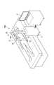
- FIG. 4is a view showing laparoscopic surgery using the medical system 100. As shown in FIG.
- the operatorprovides a plurality of holes (openings) for placing the trocar T in the abdomen B of the patient, and punctures the trocar T in the holes.
- the operatorpasses the insertion portion 10 of the treatment tool 1 of the medical system 100 and the insertion portion 20 of the endoscope 2 through the trocar T punctured in the abdomen B of the patient, Introduce into the abdominal cavity.
- the operatorholds the handle 21 and moves the endoscope 2 so that the hernia gate H to be treated is included in the display image D as shown in FIG. Change the position or orientation of If the imaging unit 22 has an optical zoom or electronic zoom function, the function is adjusted.
- the treatment unit 12 of the insertion unit 10 of the treatment tool 1is imaged. Since the operation mode of the image processing of the control unit 33 is initially set to the “normal mode”, the virtual image of the medical device is not superimposed on the display image D.
- the control unit 33 in which the operation mode is set to the “virtual image superposition mode”displays on the monitor 41 a medical device list and a message prompting the user to select the “type” and “size” of the medical device from the input unit 51
- the control unit 33 in which the operation mode is set to the “virtual image superposition mode”measures the three-dimensional relative position from the imaging unit 22 of the endoscope 2 to the treatment unit 12 of the treatment instrument (relative position measurement step).
- the measurement of the three-dimensional relative positioncan be performed by a method appropriately selected from known methods. For example, methods such as position measurement by image processing (case 1), position measurement by stereo camera (case 2), position measurement by laser etc (case 3), position measurement by sensing (case 4), etc. can be used.
- the three-dimensional relative position to the treatment unit 12can be measured using the captured image captured by the imaging unit 22 (case 1). For example, the moving treatment unit 12 can be photographed, and the three-dimensional relative position can be measured from the movement amount of the image feature. If the dimensions of the treatment section 12 are known, the three-dimensional relative position can also be measured based on the dimensions. In addition, by providing a mark such as an optical marker on the treatment unit 12, the three-dimensional relative position can be easily measured.
- Laser, light, ultrasonic waves and the likeare emitted from the imaging unit 22, and the three-dimensional relative position from the imaging unit 22 to the treatment unit 12 can be measured from the feedback information (case 3).
- the three-dimensional relative position to the treatment unit 12may be measured by performing pattern projection from the imaging unit 22 and analyzing the pattern projection result.
- a magnetic sensor or the likemay be installed in the treatment unit 12 or the imaging unit 22, and the three-dimensional relative position from the imaging unit 22 to the treatment unit 12 may be measured from position information such as a magnetic sensor received by an external antenna. Yes (case 4).
- control part 33may parallelly implement a medical device selection process and a relative-position measurement process, and may implement either one first.
- FIG. 5Ashows a display image D in which the virtual image VM1 of “mesh A” selected as the medical device is superimposed on the position where the treatment unit 12 appears.
- FIG. 5 (b)shows a display image D when the treatment tool 1 is moved.
- the control unit 33can set the transparency in the process of superimposing the virtual image VM1 on the display image D.
- the control unit 33can set the transparency in the process of superimposing the virtual image VM1 on the display image D.
- the control unit 33is a selected medical device having a relative size to the treatment unit 12 shown in the display image D based on the relative distance from the imaging unit 22 to the treatment unit 12.
- To generate a virtual image VM1 of The medical device information stored in the storage unit 36is used to generate the virtual image VM1.
- the display image D on which the virtual image VM1 is superimposedis displayed on the monitor 41. As shown in FIG. 5 (a), the operator can virtually see the situation where the treatment section 12 is holding "mesh A".
- the virtual image VM1 of the mesh Ais superimposed on the position relative to the treatment unit 12 shown in the display image D Therefore, the position where the virtual image VM1 of the mesh A is superimposed is also changed. That is, the position where the virtual image VM1 of the mesh A is superimposed follows the position of the treatment unit 12 in the display image D.
- the operatorcan move the treatment tool 1 to change the position of the virtual image VM1 of the mesh A in the display image D.
- the operatorsuperimposes the virtual image VM1 of the selected mesh A in the vicinity of the hernia gate H by moving the treatment portion 12 to the vicinity of the hernia gate H formed in the abdominal wall, as shown in FIG. 5 (b). Can.
- the virtual image VM1 of the mesh Ais superimposed on the display image D so as to have a relative size with respect to the treatment unit 12 shown in the display image D. Therefore, the size of the virtual image VM1 of the mesh A superimposed on the display image D is substantially the same size as the real image of the mesh A in the display image in which the actual mesh A actually exists in the three-dimensional space. That is, the size of the virtual image VM1 of the mesh A follows the size of the treatment unit 12 in the display image D. For example, when the treatment unit 12 is at a position far from the imaging unit 22, the virtual image VM ⁇ b> 1 of the mesh A is small and superimposed as compared to the case where the treatment unit 12 is at a position near to the imaging unit 22.
- the operatorlooks at the virtual image VM1 of the mesh A shown in the display image D, determines whether the selected mesh A has a size sufficient for closing the hernia gate H, the size etc. in the three-dimensional space It can be intuitively grasped without actually measuring it.
- the three-dimensional relative attitudecan be used in the virtual image superposition process.
- the virtual image VM1 of the mesh Ais superimposed on the display image D so as to have a posture relative to the treatment unit 12 shown in the display image D.
- the mesh virtual image VM1is generated and superimposed as an image rotated about an axis parallel to the longitudinal axis of the treatment tool 1 .
- FIG. 6Ashows a display image D on which the virtual image VM2 of “mesh B” is superimposed when “mesh B” smaller in size than “mesh A” is selected as the medical device.
- FIG. 5 (b)shows a display image D when the treatment tool 1 is moved.
- the operatormoves the treatment section 12 to the vicinity of the hernia gate H formed on the abdominal wall to display the virtual image VM2 of the selected mesh B superimposed on the vicinity of the hernia gate H, as shown in FIG. 6B. be able to.
- the operatorcan intuitively grasp that the selected mesh B does not have a necessary and sufficient size for closing the hernia gate H by looking at the virtual image VM2 of the mesh B shown in the display image D. it can.
- FIG. 7is a view showing laparoscopic surgery in which a large intestine is detached using the medical system 100. As shown in FIG.
- the operatorholds the holding portion 21 and moves the endoscope 2 so that the display image D includes the cutaway portion P of the large intestine to be treated, as shown in FIG.
- the position and the orientation of the imaging unit 22are changed.
- the treatment portion 12 of the insertion portion 10 of the treatment tool 1is imaged in the display image D shown in FIG. 7. Since the operation mode of the image processing of the control unit 33 is initially set to the “normal mode”, the virtual image of the medical device is not superimposed on the display image D.
- the operatorexamines the size of the stapler necessary and sufficient for separating the separated portion P of the large intestine before introducing the stapler for separating the separated portion P of the large intestine into the abdominal cavity. .
- the operatorsets the operation mode of the image processing of the control unit 33 to the “virtual image superposition mode”.
- the operatorselects a stapler as the type of medical device, and further selects “stapler A” which is estimated to be the optimum size.
- the virtual image superimposing stepbased on the three-dimensional relative position from the imaging portion 22 of the endoscope 2 to the treatment portion 12 of the treatment instrument, which is measured in the relative position measuring step.
- the virtual image VS1 of "stapler A"is superimposed on the display image D.
- the operatorlooks at the virtual image VS1 of the stapler A shown in the display image D, and instincts that the selected stapler A does not have the necessary and sufficient size to cut off the separated portion P of the large intestine. Can be grasped.
- the operatorreselects the "stapler B" which is larger than the stapler A.
- the control unit 33superimposes the virtual image VS2 of the "stapler B" on the display image D as shown in FIG. 9 in the virtual image superposition step.
- the operatorlooks at the virtual image VS2 of the stapler B shown in the display image D, and instincts that the selected stapler B has a necessary and sufficient size to cut off the separated portion P of the large intestine. Can be grasped.
- the operatorlooks at the virtual image of the medical device shown in the display image D and determines whether the selected medical device has a necessary and sufficient size in the three-dimensional space. Can be intuitively grasped without actually measuring dimensions and the like. The time taken for trial and error in the selection of medical devices can be reduced, and the selection of appropriate types of medical devices can be supported.
- the virtual image of the medical deviceis superimposed on the position where the treatment unit 12 appears in the display image D, but the superimposed position of the virtual image on the display image is not limited to the aspect of the above embodiment.
- the virtual imagemay be superimposed on the position where the tip or side portion of the treatment unit is located.
- the superimposition of the virtual image on the display imageis performed in the control unit 33, but the mode of the superimposition of the virtual image on the display image is not limited to the aspect of the above embodiment.
- superimposition of a virtual image on a display imagemay be performed on a display device.
- the control unit 33calculates information such as the superposition position and size necessary for superposition display, and the display device performs superposition on the display image of the virtual image based on the calculation result, and then the display image is displayed on the monitor 41. You may display it.
- the display device 4 shown in the above embodimentis configured by the monitor 41
- the display device 4may be configured by a projector.
- a projectormay be incorporated into the imaging unit 22 of the endoscope 2 and projection (projection mapping) of an image of a virtual image of a medical device may be performed by the projector in a real three-dimensional space. The operator can more intuitively select the most appropriate medical device.
- the projectoris incorporated into the imaging unit 22 of the endoscope 2, infrared pattern light may be irradiated from the projector to measure the three-dimensional relative position with the treatment unit or the like.
- the endoscope 2 shown in the above embodimentis operated by the operator holding it directly, the form of the endoscope is not limited to the endoscope 2 of the above embodiment.
- the endoscope 2Bin a medical system 100B which is a modification of the medical system 100 shown in FIG. 10, the endoscope 2B includes an articulated robot arm 21B having a plurality of joints 23.
- the three-dimensional position of the imaging unit 22 at the tip of the endoscope 2Bcan be calculated from control information of the articulated robot arm 21B.
- the treatment tool 1 shown in the above embodimentis held by the operator directly and operated, the form of the treatment tool is not limited to the treatment tool 1 of the above embodiment.
- the treatment tool 1Bincludes an articulated robot arm 11B having a plurality of joints 13.
- the three-dimensional position of the treatment section 12 at the tip of the treatment tool 1Bcan be calculated from control information of the articulated robot arm 11B.
- FIGS. 12-15A second embodiment of the present invention will be described with reference to FIGS. 12-15.
- the present embodimentis different from the first embodiment in that depth measurement in a three-dimensional space shown in a display image is performed.
- the same reference numeralsare assigned to components common to those described above, and redundant description will be omitted.
- the control unit 33 of the medical system 200adds to the three-dimensional relative position from the imaging unit 22 of the endoscope 2 to the treatment unit 12 of the treatment instrument, from the imaging unit 22 of the endoscope 2 The difference is that the "three-dimensional relative depth" to a tissue or the like (object) present in the three-dimensional space shown in the display image is also measured.
- the virtual image shape datais always stored in the storage unit 36 of the control unit 33 of the medical system 200.
- FIGS. 12 to 15an operation of the medical system 200 and an image generation method using the medical system 200 will be described with reference to FIGS. 12 to 15 by taking laparoscopic surgery in which a hernia gate formed in the abdominal wall is closed with a mesh as an example. . Only differences from the medical system 100 of the first embodiment will be described.
- the operatorsets the operation mode of the image processing of the control unit 33 to the “virtual image superposition mode”.
- the operatoroperates the input unit 51 to select “mesh A” which is estimated to be the optimum size (medical device selection step).
- the control unit 33whose operation mode is set to the “virtual image superposition mode” measures the three-dimensional relative position from the imaging unit 22 of the endoscope 2 to the treatment unit 12 of the treatment tool as in the first embodiment (relative Position measurement process).
- the relative position measurement stepthe “three-dimensional relative depth” from the imaging unit 22 of the endoscope 2 to the tissue or the like present in the three-dimensional space shown in the display image is also measured.
- the measurement of the three-dimensional relative depthcan be performed by a method appropriately selected from known methods.
- methodssuch as passive depth measurement by image processing (case P), active depth measurement by projection of a pattern or the like (case A), and the like can be used.
- the three-dimensional relative depth to the treatment unit 12can be measured using the captured image captured by the imaging unit 22 (case P). For example, the moving treatment unit 12 can be photographed, and the three-dimensional relative depth can be measured from the movement amount of the image feature.
- the imaging unit 22is configured by a stereo camera, it is possible to measure a three-dimensional relative depth from the imaging unit 22 to a tissue or the like by using a parallax image of the stereo camera.
- Laser, light, ultrasonic waves and the likeare emitted from the imaging unit 22, and the three-dimensional relative depth from the imaging unit 22 to the tissue and the like can be measured from the feedback information (case A).
- the three-dimensional relative depth to the tissue or the likemay be measured by performing pattern projection of a striped pattern or a random pattern from the imaging unit 22 and analyzing the pattern projection result.
- the control unit 33superimposes the virtual image of the selected medical device on the display image D based on the measurement results of the three-dimensional relative position and the three-dimensional relative depth (virtual image superposition step).
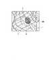
- 12 to 14show the display image D on which the virtual image VM1 of "mesh A" selected as the medical device is superimposed.
- the control unit 33sets the display image D to a wire frame F indicating unevenness of a tissue or the like present in the three-dimensional space shown in the display image D based on the measurement result of the three-dimensional relative depth.
- the operatorcan easily grasp the unevenness of the tissue or the like present in the three-dimensional space shown in the display image D by the display image D on which the wire frame F is superimposed.
- the control unit 33controls the “three-dimensional relative position” from the imaging unit 22 to the treatment unit 12 and the “three-dimensional relative position” from the imaging unit 22 to the tissue etc. existing in the three-dimensional space shown in the display image Depth is measured in real time. Further, regarding the medical device on which the virtual image is superimposed, shape data for virtual image is stored in the storage unit 36. Therefore, when the medical device on which the virtual image is superimposed is a real medical device, the control unit 33 determines whether the tissue or the like present in the three-dimensional space shown in the display image is touched (contact determination )It can be performed.
- the control unit 33determines that the tissue or the like existing in the dimensional space is in contact, as shown in FIG. 13, the control unit 33 superimposes a display indicating that the contact occurs on the display image D.
- the operatorsees the virtual image VM1 of the mesh A in the display image D and intuitively grasps whether the selected mesh A can block the hernia gate H without being obstructed by the obstacle. Can.
- the control unit 33causes the virtual image of the mesh A to contact a tissue or the like existing in a three-dimensional space when the treatment unit 12 approaches the vicinity of the hernia gate H formed in the abdominal wall as shown in FIG. It may be deformed and superimposed. The operator can more intuitively understand whether the selected mesh A can close the hernia gate H by looking at the virtual image VM1 of the mesh A deformed along the tissue or the like.
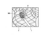
- FIG. 15shows a display image D on which the virtual image VS2 of the stapler B selected to perform the separation of the large intestine in the medical system 200 is superimposed.
- the control unit 33determines the tissue positioned on the right. It is determined that the touch image is touched, and a display indicating that the touch occurs is superimposed on the display image D.
- the control unit 33determines the tissue located on the left. It is determined that the touch image is touched, and a display indicating that the touch occurs is superimposed on the display image D. The display indicating that the contact occurs is superimposed on the place where it is determined that the contact occurs.
- the operatorlooks at the virtual image VS2 of the stapler B shown in the display image D, and intuitively determines whether the selected stapler B can disconnect the large intestine without being obstructed by the obstacle around it. It can be grasped.
- the operatorlooks at the virtual image of the medical device shown in the display image D and intuitively determines whether the selected medical device is obstructed by the obstacle. It can be grasped. The time taken for trial and error in the selection of medical devices can be reduced, and the selection of appropriate types of medical devices can be supported.
- the whole structure of the medical system 300 which concerns on this embodimentis the same as the medical system 100 which concerns on 1st embodiment.
- the differenceis that the endoscope 2C has a flexible insertion portion.
- FIG. 16shows an endoscope 2C of the medical system 300.
- a treatment tool to which the local injection needle 12b is attached as the treatment unit 12is inserted through the lumen provided in the endoscope 2C.
- the operatorinserts the local injection material into the submucosa layer slowly by piercing the local injection needle 12b at the peripheral edge beyond the lesion to lift the lesion.
- the treatment tool to which the snare 12c is attached as the treatment unit 12is inserted through the lumen provided in the endoscope 2C.
- the operatoruses the snare 12c to separate the lesion.
- the operatorneeds to select the snare 12c of the optimum size and shape in accordance with the size and shape of the lesion. Depending on the experience and skill of the caster, trial and error of the selection of the snare takes time.
- the operatorsets the operation mode of the image processing of the control unit 33 to the “virtual image superposition mode” when introducing the treatment tool to which the local injection needle 12b is attached as the treatment unit 12 into the body.
- the operatoroperates the input unit 51 to select “Snare A” which is estimated to be the optimum size (medical device selection step).
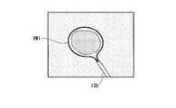
- FIG. 17shows a display image D in which the virtual image VW1 of the selected snare A is superimposed on the position where the local injection needle 12b appears in the medical system 300.
- the operatorintuitively grasps the virtual image VM1 of the snare A shown in the display image D and that the selected snare A has a necessary and sufficient size for the separation of the lesion. Can.
- FIG. 18shows a display image in which the snare B smaller in size than the snare A is selected in the medical system 300 and the virtual image VW2 of the snare B is superimposed.
- the operatorshould intuitively understand that the selected snare B does not have a necessary and sufficient size for dissection of the lesion by looking at the virtual image VM2 of the snare B shown in the display image D. Can.
- the present embodimentis different from the first embodiment to the third embodiment in that the medical device selection process is linked with the stock management system of the medical device.
- the same reference numeralsare assigned to components common to those described above, and redundant description will be omitted.
- the whole structure of the medical system 400 which concerns on this embodimentis the same as the medical system 100 which concerns on 1st embodiment.
- the control unit 33 in which the operation mode is set to the “virtual image superposition mode”displays on the monitor 41 a medical device list and a message prompting the user to select the “type” and “size” of the medical device from the input unit 51
- the control unit 33is connected to an in-hospital inventory management system of medical devices, and can display the inventory status of each medical device according to the displayed medical device list.
- the operatorcan select the medical device to be displayed as a virtual image after confirming the presence or absence of the stock. If you select a medical device that does not have an actual inventory, you can not actually use the medical device immediately, even if the selected medical device is the optimal size. If it is possible to display the stock status of medical devices, medical devices can be selected from the medical devices that can actually be used, reducing the time taken for trial and error in the selection of medical devices, and of appropriate types of medical devices. Can support selection.
- the present inventioncan be applied to a medical system provided with an endoscope.
Landscapes
- Health & Medical Sciences (AREA)
- Life Sciences & Earth Sciences (AREA)
- Surgery (AREA)
- Nuclear Medicine, Radiotherapy & Molecular Imaging (AREA)
- Biomedical Technology (AREA)
- Optics & Photonics (AREA)
- Pathology (AREA)
- Radiology & Medical Imaging (AREA)
- Biophysics (AREA)
- Engineering & Computer Science (AREA)
- Physics & Mathematics (AREA)
- Heart & Thoracic Surgery (AREA)
- Medical Informatics (AREA)
- Molecular Biology (AREA)
- Animal Behavior & Ethology (AREA)
- General Health & Medical Sciences (AREA)
- Public Health (AREA)
- Veterinary Medicine (AREA)
- Endoscopes (AREA)
Abstract
Translated fromJapaneseDescription
Translated fromJapanese本発明は、医療システムおよび医療システムを用いた画像生成方法に関する。The present invention relates to a medical system and an image generation method using the medical system.
腹腔鏡下手術では、患者の腹部などに複数の穴を開け、内視鏡、鉗子、電気メスといった各種医療機器を挿入し、内視鏡で撮像された映像を確認することで、患部の観察および施術が行われる。この腹腔鏡下手術は、切開領域が少なくて済むため、患者に対する負担を軽減することが可能である。In laparoscopic surgery, a plurality of holes are made in the patient's abdomen etc., various medical devices such as an endoscope, forceps, and an electric scalpel are inserted, and observation of the affected area is confirmed by confirming an image captured by the endoscope. And the procedure is performed. This laparoscopic surgery can reduce the burden on the patient because it requires less incision area.
腹腔鏡下手術では、処置に合わせて適切な種類の医療機器が選択され、選択された医療機器が腹腔内に挿入される。例えば、腹壁に形成されたヘルニア門をメッシュで塞ぐ腹壁ヘルニア手術においては、術者はヘルニア門を塞ぐために必要十分な最適なサイズのメッシュを選択し、選択したメッシュを腹腔内に挿入する必要がある。In laparoscopic surgery, the appropriate type of medical device is selected in accordance with the procedure, and the selected medical device is inserted into the abdominal cavity. For example, in abdominal wall hernia surgery in which the hernia gate formed in the abdominal wall is closed with mesh, the operator needs to select a mesh with the optimal size necessary and sufficient to close the hernia gate, and insert the selected mesh into the abdominal cavity is there.
術者は、内視鏡で撮像された映像を確認して、3次元空間内における組織の輪郭の長さや面積を推測し、最適なサイズのメッシュを選択する。選択したメッシュを腹腔内に挿入し、メッシュのサイズがヘルニア門に対して小さいことが判明した場合、術者はメッシュを腹腔内から取り出し、再選択したメッシュを再び腹腔内に挿入する必要がある。術者の経験や技術によっては、メッシュ選択の試行錯誤に時間がかかるという課題がある。The operator confirms the image captured by the endoscope, estimates the length and area of the contour of the tissue in the three-dimensional space, and selects a mesh of an optimal size. If the selected mesh is inserted into the abdominal cavity and the size of the mesh is found to be small relative to the hernia gate, the operator needs to remove the mesh from the abdominal cavity and reinsert the reselected mesh into the abdominal cavity . Depending on the experience and technique of the operator, there is a problem that it takes time for trial and error of mesh selection.
特許文献1には、内視鏡が取得した組織の内視鏡画像から、3次元空間内における組織の輪郭の長さや面積を計測することができる遠隔手術ロボットシステムが記載されている。遠隔手術ロボットシステムは、例えば、処置具で指定された計測点の間の距離を計測し、計測した距離情報を内視鏡画像に重畳して表示することができる。遠隔手術ロボットシステムを使用する術者は、内視鏡画像に映る組織の3次元空間内における寸法等を把握することができる。
しかしながら、特許文献1に記載の遠隔手術ロボットシステムは、3次元空間の計測を実施するためには測定点の指定等の手続きが必要で、3次元空間内における寸法等を迅速に計測できるものではなかった。また、術者は、3次元空間内における寸法等の計測結果から、最適な種類の医療機器を直感的に判断することは難しかった。However, the telesurgical robot system described in
上記事情を踏まえ、本発明は、適切な種類の医療機器の選択を支援可能な医療システムおよび医療システムを用いた画像生成方法を提供することを目的とする。In the light of the above circumstances, the present invention aims to provide a medical system capable of supporting selection of an appropriate type of medical device and an image generation method using the medical system.
上記課題を解決するために、この発明は以下の手段を提案している。
本発明に係る医療システムは、処置具と、撮像部を有する内視鏡と、前記撮像部が取得した撮像画像から表示画像を生成する制御装置と、前記表示画像を表示する表示装置と、医療機器を選択する入力装置と、を備え、前記制御装置は、前記内視鏡から前記処置具までの相対位置を計測し、前記制御装置は、前記相対位置に基づいて、前記表示画像に映る前記処置具に対して相対的な位置にあって相対的な大きさを有する前記医療機器の仮想画像を、前記表示画像に重畳する。In order to solve the above-mentioned subject, this invention proposes the following means.
A medical system according to the present invention includes a treatment tool, an endoscope having an imaging unit, a control device that generates a display image from a captured image acquired by the imaging unit, a display device that displays the display image, and medical treatment An input device for selecting a device, the control device measures a relative position from the endoscope to the treatment tool, and the control device reflects the display image based on the relative position A virtual image of the medical device at a relative position to the treatment tool and having a relative size is superimposed on the display image.
本発明に係る画像生成方法は、内視鏡の撮像部が取得した撮像画像から表示画像を生成する医療システムにおいて、入力装置を用いて医療機器を選択させる医療機器選択工程と、内視鏡から処置具までの相対位置を計測する相対位置計測工程と、前記相対位置に基づいて、前記表示画像に映る前記処置具に対して相対的な位置にあって相対的な大きさを有する前記医療機器の仮想画像を、前記表示画像に重畳する仮想画像重畳工程と、を備える。The image generation method according to the present invention is a medical system in which a display image is generated from a captured image acquired by an imaging unit of an endoscope, and a medical device selecting step of selecting a medical device using an input device; The medical device having a relative size relative to the treatment tool shown in the display image based on the relative position measuring step of measuring the relative position to the treatment tool and the relative position And a virtual image superimposing step of superimposing the virtual image on the display image.
本発明の医療システムおよび画像生成方法によれば、適切な種類の医療機器の選択を支援することができる。According to the medical system and image generation method of the present invention, selection of an appropriate type of medical device can be assisted.
(第一実施形態)
本発明の第一実施形態について、図1から図11を参照して説明する。なお、図面を見やすくするため、各構成要素の寸法等は適宜調整されている。First Embodiment
A first embodiment of the present invention will be described with reference to FIGS. In addition, in order to make a drawing legible, the dimension etc. of each component are adjusted suitably.
図1は、本実施形態に係る医療システム100の全体構成を示す図である。
医療システム100は、図1に示すように、処置具1と、内視鏡2と、制御装置3と、表示装置4と、入力装置5と、を備えている。医療システム100は、腹腔鏡下手術において、腹壁に開けた別々の孔(開口)から処置具1や内視鏡2などを挿入して行う処置を支援するシステムである。FIG. 1 is a diagram showing an entire configuration of a
As shown in FIG. 1, the
処置具1は、図1に示すように、患者の腹腔内に挿入可能な長尺の挿入部10と、挿入部10の基端側に設けられた操作部11と、を有する。術者は、患者の腹部Bに穿刺したトロッカTに挿入部10を通し、挿入部10を腹腔内に導入する。処置の種類や患部の状況により、術者は複数の処置具1を腹腔内に導入する場合もある。As shown in FIG. 1, the
挿入部10は、図1に示すように、先端に患者の患部を処置する処置部12を有する。本実施形態において処置部12は、一対の把持部材12aで構成された把持機構である。As shown in FIG. 1, the
操作部11は、一対の把持部材12aを操作する部材である。操作部11はハンドルを有しており、ハンドルを操作部11の他の部分に対して相対移動させることで、処置部12の一対の把持部材12aを開閉させる。術者は、片手で操作部11を保持して、処置部12を操作することができる。The
図2は、処置具1を除く医療システム100のハードウェア構成図である。
内視鏡2は、図1および図2に示すように、患者の腹腔内に挿入可能な長尺で硬性の挿入部20と、持手部21と、を有する。術者は、図1に示すように、患者の腹部Bに穿刺したトロッカTに挿入部20を通し、挿入部20を腹腔内に導入する。FIG. 2 is a hardware configuration diagram of the
As shown in FIGS. 1 and 2, the
図1に示すように、挿入部20は先端に、患者の腹部内の様子を撮影するためのレンズや撮像素子を有する撮像部22が設けられている。腹腔内に導入された挿入部20は、撮像部22が腹部内の処置対象の患部を撮影可能な位置に配置される。撮像部22は、光学ズームもしくは電子ズームの機能を有していてもよい。As shown in FIG. 1, the
術者は、持手部21を持って内視鏡2を移動させることで、内視鏡2の撮像部22の位置や向きを変更することができる。
なお、挿入部20は、能動的に湾曲する能動湾曲部をさらに有してもよい。挿入部20の一部に設けられた能動湾曲部を湾曲させることで、撮像部22の位置や向きを変更することができる。The operator can change the position and the orientation of the
The
持手部21の内部には、撮像部22を制御する制御信号線や、撮像部22が撮像した撮像画像を転送する伝送信号等が配線されている。A control signal line for controlling the
制御装置3は、図2に示すように、制御部33を有している。制御装置3は、内視鏡2の撮像部22が撮像した撮像画像を受信し、表示画像として表示装置4に転送する。The
制御部33は、CPU(Central Processing Unit)やメモリ等のプログラム実行可能なハードウェアを備えた装置(コンピュータ)によって構成される。制御部33の機能は、CPUを制御するプログラムを制御部33が読み込んで実行することにより、ソフトウェアの機能として実現可能である。
なお、制御部33の少なくとも一部を専用の論理回路等によって構成してもよい。
さらには、制御部33を構成する少なくとも一部のハードウェアを通信回線で結ぶことでも同様の機能を実現可能である。The
Note that at least a part of the
Furthermore, the same function can be realized by connecting at least a part of hardware configuring the
図3(a)は、制御部33の全体構成例を示す図である。
制御部33は、図3(a)に示すように、CPU34と、プログラムを読み込み可能なメモリ35と、記憶部36と、入出力制御部37と、を有している。制御部33に提供された、制御部33の動作を制御するためのプログラムがメモリ35に読み込まれ、CPU34によって実行される。FIG. 3A shows an example of the overall configuration of the
As shown in FIG. 3A, the
記憶部36は、上述したプログラムや必要なデータを記憶する不揮発性の記録媒体である。記憶部36は、例えばROMやハードディスク等で構成される。記憶部36に記録されたプログラムは、メモリ35に読み込まれ、CPU34によって実行される。The
記憶部36には、例えば、鉗子、電気メス、ステープラ、スネア、メッシュ等の腹腔内に導入される医療機器の「種別」と、医療機器の「種別」ごとの仮想画像または仮想画像をプログラム実行により生成可能な仮想画像用形状データと、が保存されている。また、サイズのバリエーションがある医療機器に関しては、「サイズ」ごとの仮想画像または「サイズ」ごとの仮想画像を生成することができる仮想画像用形状データも記憶部36に保存される。
以降の説明において、仮想画像または仮想画像用形状データのことを、「仮想画像データ」と称し、医療機器の「種別」と「サイズ」ごとの仮想画像データのことを、「医療機器情報」と称す。The
In the following description, virtual image or virtual image shape data is referred to as "virtual image data", and virtual image data for each "type" and "size" of a medical device is referred to as "medical device information". Name.
入出力制御部37は、内視鏡2からの入力データを受け取り、その入力データをCPU34等に転送する。また、入出力制御部37は、CPU34の指示に基づき、内視鏡2や表示装置4に対するデータや制御信号等を生成する。The input /
制御部33は、内視鏡2から入力データとして撮像画像を受け取り、その撮像画像をメモリ35に読み込む。メモリ35に読み込まれたプログラムに基づき、CPU34は撮像画像に対して画像処理を行う。画像処理が実施された撮像画像は、表示画像として表示装置4に転送される。The
制御部33は、通常モードと仮想画像重畳モードの少なくとも二種類の画像処理の動作モードを有している。動作モードは、プログラムによって制御される。
通常モードで動作する制御部33は、撮像画像に対して画像フォーマット変換やコントラスト調整やリサイズ処理などの画像処理を行って表示画像を生成する。
仮想画像重畳モードで動作する制御部33は、通常モードにおける画像処理に加えて、後述する医療機器の仮想画像を、表示画像に重畳する画像処理を行う。The
The
In addition to the image processing in the normal mode, the
ここで、制御部33は、1つのハードウェアに備わる装置に限られない。例えば、制御部33は、CPU34と、メモリ35と、記憶部36と、入出力制御部37とをそれぞれ別体のハードウェアとして分離した上で、ハードウェア同士を通信回線で接続することで構成してもよい。あるいは、制御部33は、記憶部36を分離して、同様に通信回線で接続することで、制御部33をクラウドシステムとして実現してもよい。Here, the
なお、制御部33は、図3(a)に示すCPU34、メモリ35、記憶部36、および入出力制御部37以外のもので、制御装置3の動作を制御するために必要なものを、さらに有してもよい。例えば、図3(b)に示すように、制御部33は、CPU34が行っていた画像処理や画像認識処理の一部もしくは全部を行う画像演算部38をさらに有してもよい。画像演算部38をさらに有することで、制御部33は、特定の画像処理や画像認識処理を高速に実行することができる。また、上記の表示画像のメモリ35から表示装置4への転送を行う画像転送部をさらに有してもよい。The
表示装置4は、制御装置3が転送した表示画像を表示する装置である。表示装置4は、LCDディスプレイ等の公知のモニタ41を有している。表示装置4は、モニタ41を複数有してもよい。表示装置4は、モニタ41の代わりに、ヘッドマウントディスプレイやプロジェクタを備えていてもよい。The
モニタ41は、制御装置3が生成したGUI(Graphical User Interface)画像をGUI表示することもできる。例えば、モニタ41は、術者に対して医療システム100の制御情報表示や注意喚起表示をGUI表示することができる。
また、制御部33が術者からの情報入力を必要とする場合、入力装置5から情報を入力することを促すメッセージや情報入力に必要なGUI表示を、表示装置4は表示することもできる。The
In addition, when the
入力装置5は、術者が制御部33に対しての指示等を入力する装置である。入力装置5は、図2に示すように、入力部51を有する。The
入力部51は、制御部33の画像処理の動作モードを選択し、また、表示画像に仮想画像として重畳表示する医療機器を選択する装置である。入力部51は、スイッチにより構成されていてもよいし、タッチパネルにより構成されていてもよい。タッチパネルはモニタ41と一体化されていてもよい。The
入力部51は、キーボードやマウスにより構成されていてもよい。この場合、制御部33は、動作モード一覧や医療機器一覧をモニタ41にGUI表示し、モニタ41に表示される一覧から、術者は所望の動作モードや医療機器をキーボードやマウスへの操作入力によって選択してもよい。制御装置3は、入力部51から術者が入力した選択情報を取得する。The
術者は、入力部51を用いて、医療機器一覧から、例えば、鉗子、電気メス、ステープラ、スネア、メッシュ等の腹腔内に導入される医療機器の「種別」を選択することができる。また、サイズのバリエーションがある医療機器に関しては「サイズ」も選択することができる。The operator can use the
次に、腹壁に形成されたヘルニア門をメッシュで塞ぐ腹腔鏡下手術を例として、医療システム100の動作および医療システム100を用いた画像生成方法を、図4および図5を参照して説明する。図4は、医療システム100を用いた腹腔鏡下手術の様子を示す図である。Next, the operation of the
術者は、患者の腹部BにトロッカTを設置するための孔(開口)を複数設け、孔にトロッカTを穿刺する。次に術者は、図4に示すように、医療システム100の処置具1の挿入部10と内視鏡2の挿入部20とを、患者の腹部Bに穿刺されたトロッカTに通して、腹腔内に導入する。The operator provides a plurality of holes (openings) for placing the trocar T in the abdomen B of the patient, and punctures the trocar T in the holes. Next, as shown in FIG. 4, the operator passes the
術者は、図4に示すように、表示画像Dに処置対象のヘルニア門Hが含まれるように、持手部21を持って内視鏡2を移動させて、内視鏡の撮像部22の位置や向きを変更する。撮像部22が光学ズームもしくは電子ズームの機能を有している場合は、その機能を調整する。図4に示す表示画像Dには、処置具1の挿入部10の処置部12が撮像されている。制御部33の画像処理の動作モードは「通常モード」に初期設定されているため、医療機器の仮想画像は表示画像Dには重畳されていない。The operator holds the
次に、術者は、ヘルニア門Hを塞ぐためのメッシュを腹腔内に導入する前に、ヘルニア門Hを塞ぐために必要十分な最適なメッシュのサイズを検討する。術者は制御部33の画像処理の動作モードを「仮想画像重畳モード」に設定する。Next, before introducing the mesh for closing the hernia gate H into the abdominal cavity, the operator examines the optimal mesh size necessary and sufficient for closing the hernia gate H. The operator sets the operation mode of the image processing of the
動作モードが「仮想画像重畳モード」に設定された制御部33は、医療機器一覧と、入力部51から医療機器の「種別」と「サイズ」を選択することを促すメッセージとをモニタ41に表示させる。
術者は、入力部51を操作し、最適なサイズであると推測した「メッシュA」を選択する(医療機器選択工程)。The
The operator operates the
動作モードが「仮想画像重畳モード」に設定された制御部33は、内視鏡2の撮像部22から処置具の処置部12までの3次元相対位置を計測する(相対位置計測工程)。
3次元相対位置の計測は公知の方法から適宜選択した方法により実施することができる。例えば、画像処理による位置計測(ケース1)、ステレオカメラによる位置計測(ケース2)、レーザ等による位置計測(ケース3)、センシングによる位置測定(ケース4)などの方法を使用することができる。The
The measurement of the three-dimensional relative position can be performed by a method appropriately selected from known methods. For example, methods such as position measurement by image processing (case 1), position measurement by stereo camera (case 2), position measurement by laser etc (case 3), position measurement by sensing (case 4), etc. can be used.
撮像部22が撮像した撮像画像を用いて、処置部12までの3次元相対位置を計測することができる(ケース1)。例えば、移動する処置部12を撮影し、画像特徴の移動量から3次元相対位置を計測することができる。また、処置部12の寸法が既知である場合は、その寸法に基づいて3次元相対位置を計測することもできる。また、処置部12に光学マーカ等の目印を設けることで、3次元相対位置を容易に計測することができる。The three-dimensional relative position to the
撮像部22をステレオカメラで構成することで、ステレオカメラの視差画像を用いて、撮像部22から処置部12までの3次元相対位置を計測することができる(ケース2)。By configuring the
レーザ、光、超音波等を撮像部22から発し、そのフィードバック情報から、撮像部22から処置部12までの3次元相対位置を計測することができる(ケース3)。撮像部22からパターン投影を行って、パターン投影結果を解析することで、処置部12までの3次元相対位置を計測してもよい。Laser, light, ultrasonic waves and the like are emitted from the
また、処置部12や撮像部22に、磁気センサ等を設置し、外部のアンテナが受信した磁気センサ等の位置情報から、撮像部22から処置部12までの3次元相対位置を計測することができる(ケース4)。In addition, a magnetic sensor or the like may be installed in the
ここで、ケース1からケース4に示した3次元相対位置の計測方法において、処置部12の3次元相対位置に加えて、処置部12の3次元相対姿勢を計測できる方法が望ましい。Here, in the method of measuring the three-dimensional relative position shown in
なお、医療機器選択工程と相対位置計測工程とは、制御部33が並列に実施してもよいし、いずれかを先に実施してもよい。In addition, the
次に、制御部33は、3次元相対位置の計測結果に基づいて、選択された医療機器の仮想画像を表示画像Dに重畳する(仮想画像重畳工程)。図5(a)は、医療機器として選択された「メッシュA」の仮想画像VM1が、処置部12が映る位置に重畳された表示画像Dを示している。図5(b)は、処置具1を移動させた場合の表示画像Dを示している。Next, the
制御部33は、仮想画像VM1の表示画像Dへの重畳処理において、透明度を設定することができる。仮想画像VM1が半透明となるように表示画像Dに重畳することで、仮想画像VM1によって重畳された部分に予め表示されていた表示内容も確認することができる。The
制御部33は、撮像部22から処置部12までの相対距離に基づいて、表示画像Dに映る処置部12に対して相対的な位置にあって相対的な大きさを有する選択された医療機器の仮想画像VM1を生成する。仮想画像VM1の生成には、記憶部36に保存されている医療機器情報を用いる。The
仮想画像VM1が重畳された表示画像Dは、モニタ41に表示される。術者は、図5(a)に示すように、仮に「メッシュA」を処置部12が保持している場合の様子を仮想的に見ることができる。The display image D on which the virtual image VM1 is superimposed is displayed on the
術者が処置具1を移動させ、表示画像D内の処置部12の位置が変更された場合、メッシュAの仮想画像VM1は表示画像Dに映る処置部12に対して相対的な位置に重畳されるため、メッシュAの仮想画像VM1が重畳される位置も変更される。すなわち、メッシュAの仮想画像VM1が重畳される位置は、表示画像D内の処置部12の位置に追従する。When the operator moves the
術者は、処置具1を移動させ、メッシュAの仮想画像VM1の表示画像D内における位置を変更することができる。術者は、図5(b)に示すように、腹壁に形成されたヘルニア門H付近に処置部12を移動させることで、選択したメッシュAの仮想画像VM1をヘルニア門H付近に重畳させることができる。The operator can move the
メッシュAの仮想画像VM1は、表示画像Dに映る処置部12に対して相対的な大きさを有するように、表示画像Dに重畳される。そのため、表示画像Dに重畳されたメッシュAの仮想画像VM1の大きさは、3次元空間内に現実のメッシュAが実際に存在する表示画像におけるメッシュAの現実画像と、ほぼ同じ大きさとなる。すなわち、メッシュAの仮想画像VM1の大きさは、表示画像D内の処置部12の大きさに追従する。例えば、処置部12が撮像部22から遠い位置にある場合は、処置部12が撮像部22から近い位置にある場合と比較して、メッシュAの仮想画像VM1は小さく重畳される。The virtual image VM1 of the mesh A is superimposed on the display image D so as to have a relative size with respect to the
術者は、表示画像Dに映るメッシュAの仮想画像VM1を見て、選択したメッシュAがヘルニア門Hを塞ぐために必要十分な大きさを有しているかを、3次元空間内における寸法等を実際に計測することなく、直感的に把握することができる。The operator looks at the virtual image VM1 of the mesh A shown in the display image D, determines whether the selected mesh A has a size sufficient for closing the hernia gate H, the size etc. in the three-dimensional space It can be intuitively grasped without actually measuring it.
相対位置計測工程において、3次元相対位置に加えて、処置部12の3次元相対姿勢を計測できる場合、仮想画像重畳工程において、3次元相対姿勢を使用することができる。メッシュAの仮想画像VM1は、表示画像Dに映る処置部12に対して相対的な姿勢を有するように、表示画像Dに重畳される。例えば、術者が処置具1を長手軸を中心に回転させた場合、メッシュの仮想画像VM1は、処置具1の長手軸と平行な軸を中心軸として回転した画像として生成されて重畳される。メッシュの仮想画像VM1を回転させることで、より直感的に、3次元空間内における寸法等を把握することができる。In the relative position measurement process, in addition to the three-dimensional relative position, when the three-dimensional relative attitude of the
図6(a)は、医療機器として「メッシュA」よりもサイズの小さな「メッシュB」を選択した場合における、「メッシュB」の仮想画像VM2が重畳された表示画像Dを示している。図5(b)は、処置具1を移動させた場合の表示画像Dを示している。FIG. 6A shows a display image D on which the virtual image VM2 of “mesh B” is superimposed when “mesh B” smaller in size than “mesh A” is selected as the medical device. FIG. 5 (b) shows a display image D when the
術者は、図6(b)に示すように、腹壁に形成されたヘルニア門H付近に処置部12を移動させることで、選択したメッシュBの仮想画像VM2をヘルニア門H付近に重畳表示させることができる。
術者は、表示画像Dに映るメッシュBの仮想画像VM2を見て、選択したメッシュBがヘルニア門Hを塞ぐために必要十分な大きさを有していないことを、直感的に把握することができる。The operator moves the
The operator can intuitively grasp that the selected mesh B does not have a necessary and sufficient size for closing the hernia gate H by looking at the virtual image VM2 of the mesh B shown in the display image D. it can.
次に、ステープラを用いて大腸の切離を行う腹腔鏡下手術を例として、医療システム100の動作および医療システム100を用いた画像生成方法を、図7から図9を参照して説明する。図7は医療システム100を用いて大腸切離を行う腹腔鏡下手術の様子を示す図である。Next, the operation of the
術者は、図7に示すように、表示画像Dに処置対象の大腸の切離部分Pが含まれるように、持手部21を持って内視鏡2を移動させて、内視鏡2の撮像部22の位置や向きを変更する。図7に示す表示画像Dには、処置具1の挿入部10の処置部12が撮像されている。制御部33の画像処理の動作モードは「通常モード」に初期設定されているため、医療機器の仮想画像は表示画像Dには重畳されていない。The operator holds the holding
次に、術者は、大腸の切離部分Pを切離するためのステープラを腹腔内に導入する前に、大腸の切離部分Pを切離するために必要十分なステープラのサイズを検討する。術者は制御部33の画像処理の動作モードを「仮想画像重畳モード」に設定する。Next, the operator examines the size of the stapler necessary and sufficient for separating the separated portion P of the large intestine before introducing the stapler for separating the separated portion P of the large intestine into the abdominal cavity. . The operator sets the operation mode of the image processing of the
術者は、医療機器選択工程において、医療機器の種別としてステープラを選択し、さらに最適なサイズであると推測した「ステープラA」を選択する。In the medical device selection step, the operator selects a stapler as the type of medical device, and further selects “stapler A” which is estimated to be the optimum size.
制御部33は、相対位置計測工程において計測した、内視鏡2の撮像部22から処置具の処置部12までの3次元相対位置に基づいて、仮想画像重畳工程において、図8に示すように「ステープラA」の仮想画像VS1を表示画像Dに重畳する。As shown in FIG. 8 in the virtual image superimposing step, based on the three-dimensional relative position from the
術者は、表示画像Dに映るステープラAの仮想画像VS1を見て、選択したステープラAが大腸の切離部分Pを切離するために必要十分な大きさを有していないことを、直感的に把握することができる。The operator looks at the virtual image VS1 of the stapler A shown in the display image D, and instincts that the selected stapler A does not have the necessary and sufficient size to cut off the separated portion P of the large intestine. Can be grasped.
術者は、医療機器選択工程において、ステープラAよりもサイズが大きい「ステープラB」を選択し直す。制御部33は、仮想画像重畳工程において、図9に示すように「ステープラB」の仮想画像VS2を表示画像Dに重畳する。In the medical device selection step, the operator reselects the "stapler B" which is larger than the stapler A. The
術者は、表示画像Dに映るステープラBの仮想画像VS2を見て、選択したステープラBが大腸の切離部分Pを切離するために必要十分な大きさを有していることを、直感的に把握することができる。The operator looks at the virtual image VS2 of the stapler B shown in the display image D, and instincts that the selected stapler B has a necessary and sufficient size to cut off the separated portion P of the large intestine. Can be grasped.
(第一実施形態の効果)
本実施形態の医療システム100によれば、術者は、表示画像Dに映る医療機器の仮想画像を見て、選択した医療機器が必要十分な大きさを有しているかを、3次元空間内における寸法等を実際に計測することなく、直感的に把握することができる。医療機器の選択の試行錯誤にかかる時間を削減し、適切な種類の医療機器の選択を支援することができる。(Effect of the first embodiment)
According to the
(変形例)
以上、本発明の第一実施形態について図面を参照して詳述したが、具体的な構成はこの実施形態に限られるものではなく、本発明の要旨を逸脱しない範囲の設計変更等も含まれる。また、上述の第一実施形態および以下で示す変形例において示した構成要素は適宜に組み合わせて構成することが可能である。(Modification)
The first embodiment of the present invention has been described in detail with reference to the drawings, but the specific configuration is not limited to this embodiment, and design changes and the like within the scope of the present invention are also included. . In addition, the components shown in the above-described first embodiment and the modifications described below can be combined appropriately.
例えば、上記実施形態では、医療機器の仮想画像は、表示画像Dにおいて処置部12が映る位置に重畳されたが、仮想画像の表示画像への重畳位置は、上記実施形態の態様に限定されない。電気メス等の他の処置部を用いる場合において、処置部の先端や側部等が位置する場所に仮想画像を重畳してもよい。For example, in the above embodiment, the virtual image of the medical device is superimposed on the position where the
例えば、上記実施形態では、仮想画像の表示画像への重畳は、制御部33において実施されていたが、仮想画像の表示画像への重畳の態様は、上記実施形態の態様に限定されない。例えば、仮想画像の表示画像への重畳は、表示装置において行われてもよい。制御部33は、重畳表示に必要な重畳位置やサイズなどの情報を算出し、その算出結果を基に表示装置が仮想画像の表示画像への重畳を行ったうえで、モニタ41に表示画像を表示してもよい。For example, in the above embodiment, the superimposition of the virtual image on the display image is performed in the
例えば、上記実施形態において示した表示装置4は、モニタ41で構成されていたが、表示装置4はプロジェクタで構成されていてもよい。プロジェクタを内視鏡2の撮像部22に組みこみ、現実の3次元空間にプロジェクタで医療機器の仮想画像の映像の投影(プロジェクションマッピング)を行ってもよい。術者は、より直感的に最適な医療機器の選択を行うことができる。プロジェクタを内視鏡2の撮像部22に組みこむ場合、プロジェクタから赤外のパターン光を対象に照射して、処置部等との3次元相対位置の計測を行ってもよい。For example, although the
例えば、上記実施形態において示した内視鏡2は、術者が直接手に持って操作するものであったが、内視鏡の形態は上記実施形態の内視鏡2に限定されない。例えば、図10に示す医療システム100の変形例である医療システム100Bにおいては、内視鏡2Bは関節23を複数有する多関節ロボットアーム21Bを有している。
医療システム100Bにおいては、内視鏡2Bの先端の撮像部22の3次元位置は、多関節ロボットアーム21Bの制御情報から算出することができる。For example, although the
In the
例えば、上記実施形態においては示した処置具1は、術者が直接手に持って操作するものであったが、処置具の形態は上記実施形態の処置具1に限定されない。例えば、図11に示す医療システム100の変形例である医療システム100Cにおいては、処置具1Bは関節13を複数有する多関節ロボットアーム11Bを有している。
医療システム100Cにおいては、処置具1Bの先端の処置部12の3次元位置は、多関節ロボットアーム11Bの制御情報から算出することができる。For example, although the
In the medical system 100C, the three-dimensional position of the
(第二実施形態)
本発明の第二実施形態について、図12から図15を参照して説明する。本実施形態は、表示画像に映る3次元空間の深度計測が行われる点が第一実施形態と異なっている。以降の説明において、既に説明したものと共通する構成については、同一の符号を付して重複する説明を省略する。Second Embodiment
A second embodiment of the present invention will be described with reference to FIGS. 12-15. The present embodiment is different from the first embodiment in that depth measurement in a three-dimensional space shown in a display image is performed. In the following description, the same reference numerals are assigned to components common to those described above, and redundant description will be omitted.
本実施形態に係る医療システム200の全体構成は、第一実施形態に係る医療システム100と同じである。医療システム200の制御部33は、相対位置計測工程において、内視鏡2の撮像部22から処置具の処置部12までの3次元相対位置に加えて、内視鏡2の撮像部22から、表示画像に映る3次元空間に存在する組織等(物体)までの「3次元相対深度」も計測する点が異なっている。The whole structure of the medical system 200 which concerns on this embodiment is the same as the
本実施形態においては、医療システム200の制御部33の記憶部36には、仮想画像用形状データが必ず保存されている。In the present embodiment, the virtual image shape data is always stored in the
次に、腹壁に形成されたヘルニア門をメッシュで塞ぐ腹腔鏡下手術を例として、医療システム200の動作および医療システム200を用いた画像生成方法を、図12から図15を参照して説明する。第一実施形態の医療システム100と異なる部分についてのみ説明を行う。Next, an operation of the medical system 200 and an image generation method using the medical system 200 will be described with reference to FIGS. 12 to 15 by taking laparoscopic surgery in which a hernia gate formed in the abdominal wall is closed with a mesh as an example. . Only differences from the
術者は制御部33の画像処理の動作モードを「仮想画像重畳モード」に設定する。
術者は、入力部51を操作し、最適なサイズであると推測した「メッシュA」を選択する(医療機器選択工程)。The operator sets the operation mode of the image processing of the
The operator operates the
動作モードが「仮想画像重畳モード」に設定された制御部33は、第一実施形態同様、内視鏡2の撮像部22から処置具の処置部12までの3次元相対位置を計測する(相対位置計測工程)。相対位置計測工程では、内視鏡2の撮像部22から、表示画像に映る3次元空間に存在する組織等までの「3次元相対深度」も計測する。The
3次元相対深度の計測は公知の方法から適宜選択した方法により実施することができる。例えば、画像処理によるパッシブ型の深度計測(ケースP)、パターン等の投影によるアクティブ型の深度計測(ケースA)、などの方法を使用することができる。The measurement of the three-dimensional relative depth can be performed by a method appropriately selected from known methods. For example, methods such as passive depth measurement by image processing (case P), active depth measurement by projection of a pattern or the like (case A), and the like can be used.
撮像部22が撮像した撮像画像を用いて、処置部12までの3次元相対深度を計測することができる(ケースP)。例えば、移動する処置部12を撮影し、画像特徴の移動量から3次元相対深度を計測することができる。撮像部22がステレオカメラで構成されている場合、ステレオカメラの視差画像を用いて、撮像部22から組織等までの3次元相対深度を計測することができる。The three-dimensional relative depth to the
レーザ、光、超音波等を撮像部22から発し、そのフィードバック情報から、撮像部22から組織等までの3次元相対深度を計測することができる(ケースA)。撮像部22から縞模様やランダムパターンのパターン投影を行って、パターン投影結果を解析することで、組織等までの3次元相対深度を計測してもよい。Laser, light, ultrasonic waves and the like are emitted from the
次に、制御部33は、3次元相対位置および3次元相対深度の計測結果に基づいて、選択された医療機器の仮想画像を表示画像Dに重畳する(仮想画像重畳工程)。図12から図14は、医療機器として選択された「メッシュA」の仮想画像VM1が重畳された表示画像Dを示している。
また、制御部33は、3次元相対深度の計測結果に基づいて、図12に示すように、表示画像Dに映る3次元空間に存在する組織等の凹凸を示すワイヤフレームFを表示画像Dに重畳する。術者は、ワイヤフレームFが重畳された表示画像Dにより、表示画像Dに映る3次元空間に存在する組織等の凹凸を容易に把握することができる。Next, the
Further, as shown in FIG. 12, the
制御部33は、仮想画像重畳工程において、撮像部22から処置部12までの「3次元相対位置」と、撮像部22から表示画像に映る3次元空間に存在する組織等までの「3次元相対深度」を、リアルタイムに計測する。また、仮想画像が重畳されている医療機器に関しては、記憶部36に仮想画像用形状データが保存されている。
そのため、制御部33は、仮想画像が重畳されている医療機器が、仮に現実の医療機器であった場合、表示画像に映る3次元空間に存在する組織等に接触するかどうかの判定(接触判定)を行うことができる。The
Therefore, when the medical device on which the virtual image is superimposed is a real medical device, the
術者が腹壁に形成されたヘルニア門H付近に処置部12を移動させた際、仮想画像が重畳されているメッシュAが、仮に同じ3次元位置に実際に存在した場合、表示画像に映る3次元空間に存在する組織等に接触すると制御部33が判定すると、図13に示すように、制御部33は接触が発生することを示す表示を表示画像Dに重畳する。When the operator moves the
術者は、表示画像Dに映るメッシュAの仮想画像VM1を見て、選択したメッシュAが、障害物に妨害されることなくヘルニア門Hを塞ぐことが可能かを、直感的に把握することができる。The operator sees the virtual image VM1 of the mesh A in the display image D and intuitively grasps whether the selected mesh A can block the hernia gate H without being obstructed by the obstacle. Can.
制御部33は、図14に示すように、腹壁に形成されたヘルニア門H付近に処置部12が接近した場合、メッシュAの仮想画像を、3次元空間に存在する組織等に接触するように変形させて重畳させてもよい。術者は、組織等に沿って変形したメッシュAの仮想画像VM1を見て、選択したメッシュAがヘルニア門Hを塞ぐことが可能かを、より直感的に把握することができる。The
図15は、医療システム200において、大腸の切離を行うために選択されたステープラBの仮想画像VS2が重畳された表示画像Dを示している。FIG. 15 shows a display image D on which the virtual image VS2 of the stapler B selected to perform the separation of the large intestine in the medical system 200 is superimposed.
術者が処置部12を表示画面Dにおいて右側に移動させた場合、図15(a)に示すように、制御部33はステープラBが仮に現実の医療機器であった場合、右側に位置する組織に接触すると判定し、接触が発生することを示す表示を表示画像Dに重畳する。When the operator moves the
術者が処置部12を表示画面Dにおいて左側に移動させた場合、図15(b)に示すように、制御部33はステープラBが仮に現実の医療機器であった場合、左側に位置する組織に接触すると判定し、接触が発生することを示す表示を表示画像Dに重畳する。接触が発生することを示す表示は、接触が発生すると判定した場所に重畳表示される。When the operator moves the
術者は、表示画像Dに映るステープラBの仮想画像VS2を見て、選択したステープラBが、周囲にある障害物に妨害されることなく大腸を切離することが可能かを、直感的に把握することができる。The operator looks at the virtual image VS2 of the stapler B shown in the display image D, and intuitively determines whether the selected stapler B can disconnect the large intestine without being obstructed by the obstacle around it. It can be grasped.
(第二実施形態の効果)
本実施形態の医療システム200によれば、術者は、表示画像Dに映る医療機器の仮想画像を見て、選択した医療機器が、障害物に妨害されることがないかを、直感的に把握することができる。医療機器の選択の試行錯誤にかかる時間を削減し、適切な種類の医療機器の選択を支援することができる。(Effect of the second embodiment)
According to the medical system 200 of the present embodiment, the operator looks at the virtual image of the medical device shown in the display image D and intuitively determines whether the selected medical device is obstructed by the obstacle. It can be grasped. The time taken for trial and error in the selection of medical devices can be reduced, and the selection of appropriate types of medical devices can be supported.
(第三実施形態)
本発明の第三実施形態について、図16から図18を参照して説明する。本実施形態は、内視鏡が硬性でなく軟性である点が第一実施形態および第二実施形態と異なっている。以降の説明において、既に説明したものと共通する構成については、同一の符号を付して重複する説明を省略する。Third Embodiment
A third embodiment of the present invention will be described with reference to FIGS. The present embodiment is different from the first and second embodiments in that the endoscope is not rigid but flexible. In the following description, the same reference numerals are assigned to components common to those described above, and redundant description will be omitted.
本実施形態に係る医療システム300の全体構成は、第一実施形態に係る医療システム100と同じである。内視鏡2Cが軟性の挿入部を有している点が異なっている。
次に、EMR手術を例として、医療システム300の動作および医療システム300を用いた画像生成方法を、図16から図18を参照して説明する。The whole structure of the medical system 300 which concerns on this embodiment is the same as the
Next, the operation of the medical system 300 and an image generation method using the medical system 300 will be described with reference to FIGS. 16 to 18 by taking EMR surgery as an example.
図16は医療システム300の内視鏡2Cを示している。
医療システム300において、図16(a)に示すように、処置部12として局注針12bが取り付けられた処置具が、内視鏡2Cに設けられたルーメンに挿通される。術者は、病変の向こう側の辺縁部に局注針12bを刺して、粘膜下層にゆっくり局注材を入れ、病変を持ち上げる。その後、図16(b)に示すように、処置部12としてスネア12cが取り付けられた処置具が、内視鏡2Cに設けられたルーメンに挿通される。術者はスネア12cを用いて、病変の切離を行う。
術者は、病変の大きさや形状に合わせて、最適な大きさと形状のスネア12cを選択する必要がある。術者の経験や技術によっては、スネアの選択の試行錯誤に時間がかかる。FIG. 16 shows an endoscope 2C of the medical system 300.
In the medical system 300, as shown in FIG. 16A, a treatment tool to which the
The operator needs to select the
そこで術者は、処置部12として局注針12bが取り付けられた処置具を体内に導入している際に、制御部33の画像処理の動作モードを「仮想画像重畳モード」に設定する。術者は、入力部51を操作し、最適なサイズであると推測した「スネアA」を選択する(医療機器選択工程)。Therefore, the operator sets the operation mode of the image processing of the
図17は、医療システム300において、選択されたスネアAの仮想画像VW1が、局注針12bが映る位置に重畳された表示画像Dを示している。
術者は、表示画像Dに映るスネアAの仮想画像VM1を見て、選択したスネアAが病変の切離のために必要十分な大きさを有していることを、直感的に把握することができる。FIG. 17 shows a display image D in which the virtual image VW1 of the selected snare A is superimposed on the position where the
The operator intuitively grasps the virtual image VM1 of the snare A shown in the display image D and that the selected snare A has a necessary and sufficient size for the separation of the lesion. Can.
図18は、医療システム300において、スネアAよりもサイズが小さいスネアBが選択され、スネアBの仮想画像VW2が重畳された表示画像を示している。
術者は、表示画像Dに映るスネアBの仮想画像VM2を見て、選択したスネアBが病変の切離のために必要十分な大きさを有していないことを、直感的に把握することができる。FIG. 18 shows a display image in which the snare B smaller in size than the snare A is selected in the medical system 300 and the virtual image VW2 of the snare B is superimposed.
The operator should intuitively understand that the selected snare B does not have a necessary and sufficient size for dissection of the lesion by looking at the virtual image VM2 of the snare B shown in the display image D. Can.
(第三実施形態の効果)
本実施形態の医療システム300によれば、軟性の内視鏡を用いる場合であっても、術者は、表示画像Dに映る医療機器の仮想画像を見て、選択した医療機器が必要十分な大きさを有しているかを、3次元空間内における寸法等を実際に計測することなく、直感的に把握することができる。医療機器の選択の試行錯誤にかかる時間を削減し、適切な種類の医療機器の選択を支援することができる。(Effect of the third embodiment)
According to the medical system 300 of the present embodiment, even in the case of using a flexible endoscope, the operator looks at the virtual image of the medical device shown in the display image D, and the selected medical device is necessary and sufficient. Whether it has a size can be intuitively grasped without actually measuring the dimensions and the like in the three-dimensional space. The time taken for trial and error in the selection of medical devices can be reduced, and the selection of appropriate types of medical devices can be supported.
(第四実施形態)
本発明の第四実施形態について説明する。本実施形態は、医療機器選択工程が医療機器の在庫管理システムと連携している点が第一実施形態から第三実施形態と異なっている。以降の説明において、既に説明したものと共通する構成については、同一の符号を付して重複する説明を省略する。Fourth Embodiment
A fourth embodiment of the present invention will be described. The present embodiment is different from the first embodiment to the third embodiment in that the medical device selection process is linked with the stock management system of the medical device. In the following description, the same reference numerals are assigned to components common to those described above, and redundant description will be omitted.
本実施形態に係る医療システム400の全体構成は、第一実施形態に係る医療システム100と同じである。The whole structure of the medical system 400 which concerns on this embodiment is the same as the
動作モードが「仮想画像重畳モード」に設定された制御部33は、医療機器一覧と、入力部51から医療機器の「種別」と「サイズ」を選択することを促すメッセージとをモニタ41に表示させる。
制御部33は院内の医療機器の在庫管理システムと接続されており、表示される医療機器一覧に合わせて、各医療機器の在庫状況を表示することができる。
術者は、在庫の有無を確認したうえで、仮想画像として表示する医療機器を選択することができる。実際の在庫がない医療機器を選択した場合、選択した医療機器が最適なサイズであったとしても、その医療機器を実際にすぐに使用することはできない。医療機器の在庫状況を表示することができれば、実際に使用できる医療機器から、医療機器を選択することができ、医療機器の選択の試行錯誤にかかる時間を削減し、適切な種類の医療機器の選択を支援することができる。The
The
The operator can select the medical device to be displayed as a virtual image after confirming the presence or absence of the stock. If you select a medical device that does not have an actual inventory, you can not actually use the medical device immediately, even if the selected medical device is the optimal size. If it is possible to display the stock status of medical devices, medical devices can be selected from the medical devices that can actually be used, reducing the time taken for trial and error in the selection of medical devices, and of appropriate types of medical devices. Can support selection.
本発明は、内視鏡を備える医療システムに適用することができる。The present invention can be applied to a medical system provided with an endoscope.
100,100B、100C、200,300,400 医療システム
1、1B 処置具
10 挿入部
11 操作部
12 処置部
12a 把持部材
12b 局注針
12c スネア
2、2B、2C 内視鏡
20 挿入部
21 持手部
22 撮像部
3 制御装置
33 制御部
35 メモリ
36 記憶部
37 入出力制御部
38 画像演算部
4 表示装置
41 モニタ
5 入力装置
51 入力部100, 100B, 100C, 200, 300, 400
Claims (12)
Translated fromJapanese撮像部を有する内視鏡と、
前記撮像部が取得した撮像画像から表示画像を生成する制御装置と、
前記表示画像を表示する表示装置と、
医療機器を選択する入力装置と、を備え、
前記制御装置は、前記内視鏡から前記処置具までの相対位置を計測し、
前記制御装置は、前記相対位置に基づいて、前記表示画像に映る前記処置具に対して相対的な位置にあって相対的な大きさを有する前記医療機器の仮想画像を、前記表示画像に重畳する、
医療システム。Treatment tools,
An endoscope having an imaging unit;
A control device that generates a display image from the captured image acquired by the imaging unit;
A display device for displaying the display image;
And an input device for selecting a medical device,
The control device measures the relative position from the endoscope to the treatment tool,
The control device superimposes, on the display image, a virtual image of the medical device having a relative size at a position relative to the treatment tool shown in the display image based on the relative position. Do,
Medical system.
前記制御装置は、前記相対姿勢に基づいて、前記表示画像に映る前記処置具に対して相対的な姿勢となる前記医療機器の仮想画像を、前記表示画像に重畳する、
請求項1に記載の医療システム。The control device measures the relative posture of the treatment tool with respect to the endoscope,
The control device superimposes, on the display image, a virtual image of the medical device, which is a posture relative to the treatment tool shown in the display image, based on the relative posture.
The medical system according to claim 1.
前記制御装置は、前記動作モードが前記通常モードに設定されている場合、前記仮想画像を重畳しない前記表示画像を生成し、
前記制御装置は、前記動作モードが前記仮想画像重畳モードに設定されている場合、前記仮想画像を重畳した前記表示画像を生成する、
請求項1に記載の医療システム。The control device has at least two operation modes of a normal mode and a virtual image superposition mode.
The control device generates the display image in which the virtual image is not superimposed, when the operation mode is set to the normal mode.
The control device generates the display image on which the virtual image is superimposed, when the operation mode is set to the virtual image superposition mode.
The medical system according to claim 1.
前記制御装置は、前記相対位置および前記相対深度に基づいて、前記仮想画像が前記表示画像に重畳されている前記医療機器が、仮に現実の医療機器であった場合、前記表示画像に映る物体に接触するかどうかの判定を行う、
請求項1から請求項3のいずれか一項に記載の医療システム。The control device measures relative depth to an object shown in the display image;
If the medical device on which the virtual image is superimposed on the display image is a real medical device based on the relative position and the relative depth, the control device is an object shown in the display image. Determine if it will touch,
The medical system according to any one of claims 1 to 3.
請求項4に記載の医療システム。The control device superimposes, on the display image, a wire frame indicating unevenness of an object shown in the display image based on the relative depth.
The medical system according to claim 4.
請求項1から請求項3のいずれか一項に記載の医療システム。The control device stores medical device information of the selectable medical device, and displays the selectable medical device on the display device based on the medical device information.
The medical system according to any one of claims 1 to 3.
請求項6に記載の医療システム。The medical device information includes inventory information of the medical device in a hospital.
The medical system according to claim 6.
請求項1から請求項7のいずれか一項に記載の医療システム。The control apparatus superimposes the virtual image of the medical device on the display image such that the virtual image of the medical device is translucent.
The medical system according to any one of claims 1 to 7.
入力装置を用いて医療機器を選択させる医療機器選択工程と、
内視鏡から処置具までの相対位置を計測する相対位置計測工程と、
前記相対位置に基づいて、前記表示画像に映る前記処置具に対して相対的な位置にあって相対的な大きさを有する前記医療機器の仮想画像を、前記表示画像に重畳する仮想画像重畳工程と、を備える、
画像生成方法。In a medical system that generates a display image from a captured image acquired by an imaging unit of an endoscope
A medical device selection step of selecting a medical device using an input device;
A relative position measuring step of measuring a relative position from the endoscope to the treatment tool;
Virtual image superimposing step of superimposing a virtual image of the medical device having a relative size at a position relative to the treatment tool shown in the display image based on the relative position on the display image And
Image generation method.
前記仮想画像重畳工程は、前記相対姿勢に基づいて、前記表示画像に映る前記処置具に対して相対的な姿勢となる前記医療機器の仮想画像を、前記表示画像に重畳する、
請求項9に記載の画像生成方法。In the relative position measurement step, in addition to the relative position, the relative posture of the treatment tool with respect to the endoscope is measured.
The virtual image superimposing step superimposes, on the display image, a virtual image of the medical device which is in a posture relative to the treatment tool shown in the display image based on the relative posture.
The image generation method according to claim 9.
前記動作モードが前記仮想画像重畳モードに設定されている場合のみ、医療機器選択工程と、相対位置計測工程と、仮想画像重畳工程と、を実施する、
請求項9に記載の画像生成方法。Has at least two operation modes: normal mode and virtual image superposition mode,
The medical device selection step, the relative position measurement step, and the virtual image superposition step are performed only when the operation mode is set to the virtual image superposition mode.
The image generation method according to claim 9.
前記仮想画像重畳工程は、前記相対位置および前記相対深度に基づいて、仮想画像が前記表示画像に重畳されている前記医療機器が、仮に現実の医療機器であった場合、前記表示画像に映る物体に接触するかどうかの判定を行い、前記接触が発生すると判断した場合は、接触を示す表示を、前記表示画像に重畳する、
請求項9に記載の画像生成方法。The relative position measurement step measures relative depth to an object shown in the display image,
In the virtual image superimposing step, when the medical device on which the virtual image is superimposed on the display image is an actual medical device based on the relative position and the relative depth, an object shown in the display image To determine whether or not the touch occurs, and when it is determined that the touch occurs, a display indicating the touch is superimposed on the display image.
The image generation method according to claim 9.
Priority Applications (1)
| Application Number | Priority Date | Filing Date | Title |
|---|---|---|---|
| PCT/JP2017/029614WO2019035206A1 (en) | 2017-08-18 | 2017-08-18 | Medical system and image generation method |
Applications Claiming Priority (1)
| Application Number | Priority Date | Filing Date | Title |
|---|---|---|---|
| PCT/JP2017/029614WO2019035206A1 (en) | 2017-08-18 | 2017-08-18 | Medical system and image generation method |
Publications (1)
| Publication Number | Publication Date |
|---|---|
| WO2019035206A1true WO2019035206A1 (en) | 2019-02-21 |
Family
ID=65362425
Family Applications (1)
| Application Number | Title | Priority Date | Filing Date |
|---|---|---|---|
| PCT/JP2017/029614CeasedWO2019035206A1 (en) | 2017-08-18 | 2017-08-18 | Medical system and image generation method |
Country Status (1)
| Country | Link |
|---|---|
| WO (1) | WO2019035206A1 (en) |
Cited By (1)
| Publication number | Priority date | Publication date | Assignee | Title |
|---|---|---|---|---|
| CN116171122A (en)* | 2020-09-10 | 2023-05-26 | 奥林巴斯株式会社 | Medical system and control method |
Citations (4)
| Publication number | Priority date | Publication date | Assignee | Title |
|---|---|---|---|---|
| JPH05337118A (en)* | 1992-06-04 | 1993-12-21 | Olympus Optical Co Ltd | Scope holder |
| JPH08332169A (en)* | 1995-06-08 | 1996-12-17 | Olympus Optical Co Ltd | Intracoelomscope |
| JPH0938030A (en)* | 1995-07-28 | 1997-02-10 | Shimadzu Corp | Endoscope device |
| JP2002238844A (en)* | 2001-02-16 | 2002-08-27 | Olympus Optical Co Ltd | Endoscope device |
- 2017
- 2017-08-18WOPCT/JP2017/029614patent/WO2019035206A1/ennot_activeCeased
Patent Citations (4)
| Publication number | Priority date | Publication date | Assignee | Title |
|---|---|---|---|---|
| JPH05337118A (en)* | 1992-06-04 | 1993-12-21 | Olympus Optical Co Ltd | Scope holder |
| JPH08332169A (en)* | 1995-06-08 | 1996-12-17 | Olympus Optical Co Ltd | Intracoelomscope |
| JPH0938030A (en)* | 1995-07-28 | 1997-02-10 | Shimadzu Corp | Endoscope device |
| JP2002238844A (en)* | 2001-02-16 | 2002-08-27 | Olympus Optical Co Ltd | Endoscope device |
Cited By (1)
| Publication number | Priority date | Publication date | Assignee | Title |
|---|---|---|---|---|
| CN116171122A (en)* | 2020-09-10 | 2023-05-26 | 奥林巴斯株式会社 | Medical system and control method |
Similar Documents
| Publication | Publication Date | Title |
|---|---|---|
| JP7275204B2 (en) | System and method for on-screen menus in telemedicine systems | |
| JP7080945B2 (en) | Systems and methods for on-screen identification of instruments in remote-controlled medical systems | |
| JP7086150B2 (en) | Systems and methods for rendering on-screen identification of instruments in remote-controlled medical systems | |
| CN109890311B (en) | Reconfigurable display in computer-assisted teleoperated surgery | |
| CN108778180B (en) | System and method for removing occluding objects in surgical images and/or video | |
| EP1937176B1 (en) | Auxiliary image display and manipulation on a computer display in a medical robotic system | |
| US9615890B2 (en) | Surgical robot system and method of controlling the same | |
| KR101038417B1 (en) | Surgical Robot System and Its Control Method | |
| JP2019162339A (en) | Surgery supporting system and display method | |
| WO2024145341A1 (en) | Systems and methods for generating 3d navigation interfaces for medical procedures | |
| US20250205003A1 (en) | Robotic surgical system and method for providing a stadium view with arm set-up guidance | |
| KR100962472B1 (en) | Surgical robot system and control method thereof | |
| KR101715026B1 (en) | Surgical robot system and motion restriction control method thereof | |
| WO2019035206A1 (en) | Medical system and image generation method | |
| KR101683057B1 (en) | Surgical robot system and motion restriction control method thereof | |
| CN118284380A (en) | Navigation assistance for an instrument | |
| JP7495242B2 (en) | Medical image diagnostic device, surgical support robot device, surgical support robot control device and control program | |
| CN117355862A (en) | Systems, methods, and media including instructions for connecting model structures representing anatomic passageways | |
| US11850004B2 (en) | Systems and methods for determining an arrangement of explanted tissue and for displaying tissue information | |
| WO2022147074A1 (en) | Systems and methods for tracking objects crossing body wall for operations associated with a computer-assisted system | |
| JP2024514640A (en) | Blending visualized directly on the rendered element showing blended elements and actions occurring on-screen and off-screen | |
| CN119014982A (en) | System and method for generating workspace geometry of an instrument |
Legal Events
| Date | Code | Title | Description |
|---|---|---|---|
| 121 | Ep: the epo has been informed by wipo that ep was designated in this application | Ref document number:17921626 Country of ref document:EP Kind code of ref document:A1 | |
| NENP | Non-entry into the national phase | Ref country code:DE | |
| 122 | Ep: pct application non-entry in european phase | Ref document number:17921626 Country of ref document:EP Kind code of ref document:A1 | |
| NENP | Non-entry into the national phase | Ref country code:JP |