WO2019031291A1 - Vehicle display device - Google Patents
Vehicle display deviceDownload PDFInfo
- Publication number
- WO2019031291A1 WO2019031291A1PCT/JP2018/028472JP2018028472WWO2019031291A1WO 2019031291 A1WO2019031291 A1WO 2019031291A1JP 2018028472 WJP2018028472 WJP 2018028472WWO 2019031291 A1WO2019031291 A1WO 2019031291A1
- Authority
- WO
- WIPO (PCT)
- Prior art keywords
- vehicle
- image
- information
- display
- reference value
- Prior art date
- Legal status (The legal status is an assumption and is not a legal conclusion. Google has not performed a legal analysis and makes no representation as to the accuracy of the status listed.)
- Ceased
Links
Images


Classifications
- G—PHYSICS
- G06—COMPUTING OR CALCULATING; COUNTING
- G06T—IMAGE DATA PROCESSING OR GENERATION, IN GENERAL
- G06T11/00—2D [Two Dimensional] image generation
- B—PERFORMING OPERATIONS; TRANSPORTING
- B60—VEHICLES IN GENERAL
- B60K—ARRANGEMENT OR MOUNTING OF PROPULSION UNITS OR OF TRANSMISSIONS IN VEHICLES; ARRANGEMENT OR MOUNTING OF PLURAL DIVERSE PRIME-MOVERS IN VEHICLES; AUXILIARY DRIVES FOR VEHICLES; INSTRUMENTATION OR DASHBOARDS FOR VEHICLES; ARRANGEMENTS IN CONNECTION WITH COOLING, AIR INTAKE, GAS EXHAUST OR FUEL SUPPLY OF PROPULSION UNITS IN VEHICLES
- B60K35/00—Instruments specially adapted for vehicles; Arrangement of instruments in or on vehicles
- B60K35/10—Input arrangements, i.e. from user to vehicle, associated with vehicle functions or specially adapted therefor
- B—PERFORMING OPERATIONS; TRANSPORTING
- B60—VEHICLES IN GENERAL
- B60K—ARRANGEMENT OR MOUNTING OF PROPULSION UNITS OR OF TRANSMISSIONS IN VEHICLES; ARRANGEMENT OR MOUNTING OF PLURAL DIVERSE PRIME-MOVERS IN VEHICLES; AUXILIARY DRIVES FOR VEHICLES; INSTRUMENTATION OR DASHBOARDS FOR VEHICLES; ARRANGEMENTS IN CONNECTION WITH COOLING, AIR INTAKE, GAS EXHAUST OR FUEL SUPPLY OF PROPULSION UNITS IN VEHICLES
- B60K35/00—Instruments specially adapted for vehicles; Arrangement of instruments in or on vehicles
- B60K35/20—Output arrangements, i.e. from vehicle to user, associated with vehicle functions or specially adapted therefor
- B60K35/21—Output arrangements, i.e. from vehicle to user, associated with vehicle functions or specially adapted therefor using visual output, e.g. blinking lights or matrix displays
- B60K35/23—Head-up displays [HUD]
- B—PERFORMING OPERATIONS; TRANSPORTING
- B60—VEHICLES IN GENERAL
- B60K—ARRANGEMENT OR MOUNTING OF PROPULSION UNITS OR OF TRANSMISSIONS IN VEHICLES; ARRANGEMENT OR MOUNTING OF PLURAL DIVERSE PRIME-MOVERS IN VEHICLES; AUXILIARY DRIVES FOR VEHICLES; INSTRUMENTATION OR DASHBOARDS FOR VEHICLES; ARRANGEMENTS IN CONNECTION WITH COOLING, AIR INTAKE, GAS EXHAUST OR FUEL SUPPLY OF PROPULSION UNITS IN VEHICLES
- B60K35/00—Instruments specially adapted for vehicles; Arrangement of instruments in or on vehicles
- B60K35/20—Output arrangements, i.e. from vehicle to user, associated with vehicle functions or specially adapted therefor
- B60K35/28—Output arrangements, i.e. from vehicle to user, associated with vehicle functions or specially adapted therefor characterised by the type of the output information, e.g. video entertainment or vehicle dynamics information; characterised by the purpose of the output information, e.g. for attracting the attention of the driver
- G—PHYSICS
- G02—OPTICS
- G02B—OPTICAL ELEMENTS, SYSTEMS OR APPARATUS
- G02B27/00—Optical systems or apparatus not provided for by any of the groups G02B1/00 - G02B26/00, G02B30/00
- G02B27/01—Head-up displays
- G—PHYSICS
- G06—COMPUTING OR CALCULATING; COUNTING
- G06T—IMAGE DATA PROCESSING OR GENERATION, IN GENERAL
- G06T11/00—2D [Two Dimensional] image generation
- G06T11/001—Texturing; Colouring; Generation of texture or colour
- G—PHYSICS
- G06—COMPUTING OR CALCULATING; COUNTING
- G06V—IMAGE OR VIDEO RECOGNITION OR UNDERSTANDING
- G06V20/00—Scenes; Scene-specific elements
- G06V20/50—Context or environment of the image
- G06V20/56—Context or environment of the image exterior to a vehicle by using sensors mounted on the vehicle
- G06V20/58—Recognition of moving objects or obstacles, e.g. vehicles or pedestrians; Recognition of traffic objects, e.g. traffic signs, traffic lights or roads
- B—PERFORMING OPERATIONS; TRANSPORTING
- B60—VEHICLES IN GENERAL
- B60K—ARRANGEMENT OR MOUNTING OF PROPULSION UNITS OR OF TRANSMISSIONS IN VEHICLES; ARRANGEMENT OR MOUNTING OF PLURAL DIVERSE PRIME-MOVERS IN VEHICLES; AUXILIARY DRIVES FOR VEHICLES; INSTRUMENTATION OR DASHBOARDS FOR VEHICLES; ARRANGEMENTS IN CONNECTION WITH COOLING, AIR INTAKE, GAS EXHAUST OR FUEL SUPPLY OF PROPULSION UNITS IN VEHICLES
- B60K2360/00—Indexing scheme associated with groups B60K35/00 or B60K37/00 relating to details of instruments or dashboards
- B60K2360/16—Type of output information
- B60K2360/166—Navigation
- B—PERFORMING OPERATIONS; TRANSPORTING
- B60—VEHICLES IN GENERAL
- B60K—ARRANGEMENT OR MOUNTING OF PROPULSION UNITS OR OF TRANSMISSIONS IN VEHICLES; ARRANGEMENT OR MOUNTING OF PLURAL DIVERSE PRIME-MOVERS IN VEHICLES; AUXILIARY DRIVES FOR VEHICLES; INSTRUMENTATION OR DASHBOARDS FOR VEHICLES; ARRANGEMENTS IN CONNECTION WITH COOLING, AIR INTAKE, GAS EXHAUST OR FUEL SUPPLY OF PROPULSION UNITS IN VEHICLES
- B60K2360/00—Indexing scheme associated with groups B60K35/00 or B60K37/00 relating to details of instruments or dashboards
- B60K2360/16—Type of output information
- B60K2360/179—Distances to obstacles or vehicles
- B—PERFORMING OPERATIONS; TRANSPORTING
- B60—VEHICLES IN GENERAL
- B60K—ARRANGEMENT OR MOUNTING OF PROPULSION UNITS OR OF TRANSMISSIONS IN VEHICLES; ARRANGEMENT OR MOUNTING OF PLURAL DIVERSE PRIME-MOVERS IN VEHICLES; AUXILIARY DRIVES FOR VEHICLES; INSTRUMENTATION OR DASHBOARDS FOR VEHICLES; ARRANGEMENTS IN CONNECTION WITH COOLING, AIR INTAKE, GAS EXHAUST OR FUEL SUPPLY OF PROPULSION UNITS IN VEHICLES
- B60K2360/00—Indexing scheme associated with groups B60K35/00 or B60K37/00 relating to details of instruments or dashboards
- B60K2360/20—Optical features of instruments
- B60K2360/21—Optical features of instruments using cameras
- B—PERFORMING OPERATIONS; TRANSPORTING
- B60—VEHICLES IN GENERAL
- B60K—ARRANGEMENT OR MOUNTING OF PROPULSION UNITS OR OF TRANSMISSIONS IN VEHICLES; ARRANGEMENT OR MOUNTING OF PLURAL DIVERSE PRIME-MOVERS IN VEHICLES; AUXILIARY DRIVES FOR VEHICLES; INSTRUMENTATION OR DASHBOARDS FOR VEHICLES; ARRANGEMENTS IN CONNECTION WITH COOLING, AIR INTAKE, GAS EXHAUST OR FUEL SUPPLY OF PROPULSION UNITS IN VEHICLES
- B60K35/00—Instruments specially adapted for vehicles; Arrangement of instruments in or on vehicles
- B60K35/80—Arrangements for controlling instruments
- B60K35/81—Arrangements for controlling instruments for controlling displays
- G—PHYSICS
- G02—OPTICS
- G02B—OPTICAL ELEMENTS, SYSTEMS OR APPARATUS
- G02B27/00—Optical systems or apparatus not provided for by any of the groups G02B1/00 - G02B26/00, G02B30/00
- G02B27/01—Head-up displays
- G02B27/0101—Head-up displays characterised by optical features
- G02B2027/0138—Head-up displays characterised by optical features comprising image capture systems, e.g. camera
- G—PHYSICS
- G02—OPTICS
- G02B—OPTICAL ELEMENTS, SYSTEMS OR APPARATUS
- G02B27/00—Optical systems or apparatus not provided for by any of the groups G02B1/00 - G02B26/00, G02B30/00
- G02B27/01—Head-up displays
- G02B27/0101—Head-up displays characterised by optical features
- G02B2027/014—Head-up displays characterised by optical features comprising information/image processing systems
- G—PHYSICS
- G02—OPTICS
- G02B—OPTICAL ELEMENTS, SYSTEMS OR APPARATUS
- G02B27/00—Optical systems or apparatus not provided for by any of the groups G02B1/00 - G02B26/00, G02B30/00
- G02B27/01—Head-up displays
- G02B27/0179—Display position adjusting means not related to the information to be displayed
- G02B2027/0183—Adaptation to parameters characterising the motion of the vehicle
Definitions
- the present inventionrelates to a display device for a vehicle.
- a display device for a vehicleby projecting a display image on a light transmitting member such as a windshield of a vehicle, a virtual image is made visible to a passenger sitting in a driver's seat using light of the display image reflected by the windshield
- a so-called head up display (HUD) deviceFor example, the image processing device disclosed in Patent Document 1 detects the relative position of the division line provided on the traveling path with respect to the vehicle, and the approaching display element which is a predetermined display element and the non-appearing display element And a display image was generated so as to be viewed in a superimposed manner and projected onto the windshield.
- the detection target in the vicinity of the vehicleis easy for the passenger to visually recognize, and the detection target at a distance of the vehicle can not be visually recognized or is difficult to visually recognize. That is, it can be said that the degree of importance of the information on the detection object in the vicinity of the vehicle is low, and the degree of importance of the information on the object distant from the vehicle is high.
- An object of the present inventionis to provide a display device for a vehicle which can make a passenger more surely recognize important information which is difficult to view.
- a display device for a vehicleis: A display unit for displaying a display image; An object information acquisition unit that acquires object information on an object present around a vehicle on which the display device for a vehicle is mounted; An image generation unit that generates the display image; Equipped with The display area of the display image comprises a sharp area and a blurred area, The image generation unit generates an information image of the object in the clear area when the distance from the vehicle to the object is equal to or larger than a first reference value, or from the vehicle to the object. Generating the information image of the object in the blurred region if the distance is less than or equal to the first reference value; The information image of the blurred region is generated more blurred than the information image of the sharp region. It is characterized by
- a display device for a vehicleis: A display unit for displaying a display image; An object information acquisition unit that acquires object information on an object present around a vehicle on which the display device for a vehicle is mounted; An image generation unit that generates the display image; Equipped with The display area of the display image comprises a sharp area and a blurred area, The image generation unit generates an information image of the object in the clear area when the distance from the vehicle to the object is equal to or larger than a first reference value, or from the vehicle to the object.
- the information image of the object in the blurred regionif the distance is less than a second reference value or The information image of the blurred region is generated more blurred than the information image of the sharp region;
- the first reference valueis equal to or greater than the second reference value. It is characterized by
- FIG. 1It is the schematic which shows the structure of the head-up display apparatus which is one form of the display apparatus for vehicles. It is a block diagram of a display for vehicles. It is the figure which showed the distance from the vehicle to a target object in 1st Embodiment of the display apparatus for vehicles shown by FIG. 2, correspondence of a clear area
- FIG. 7is a diagram showing the correspondence between the distance from the vehicle to the object, the clear area, and the blur area when the speed of the vehicle in the first embodiment of the vehicle display device shown in FIG. 2 is greater than FIG. 3. It is an example of a display when the speed of the vehicle in 1st Embodiment of the display apparatus for vehicles shown by FIG. 2 is larger than FIG. It is a display example in case the viewpoint of the passenger in 1st Embodiment of the display apparatus for vehicles shown by FIG. 2 exists in the vicinity of a vehicle. It is the figure which showed the distance from the vehicle to a target object in 2nd Embodiment of the display apparatus for vehicles shown by FIG. 2, correspondence of a clear area
- FIG. 10is a view showing the correspondence between the distance from the vehicle to the object, the clear area, and the blur area when the speed of the vehicle in the second embodiment of the vehicle display device shown in FIG. 2 is larger than FIG. 9. It is an example of a display when the speed of the vehicle in 2nd Embodiment of the display apparatus for vehicles shown by FIG. 2 is larger than FIG. It is a display example in case the viewpoint of the passenger in 2nd Embodiment of the display apparatus for vehicles shown by FIG.
- FIG. 2exists in the vicinity of a vehicle. It is another display example of the information image superimposition in 2nd Embodiment of the display apparatus for vehicles shown by FIG. It is an example of a display of pedestrian detection in a display for vehicles shown in Drawing 2. It is an example of a display of the direction indication in the display apparatus for vehicles shown by FIG.
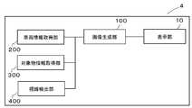
- FIG. 1shows a schematic view of the configuration of a head-up display device (hereinafter also referred to as a HUD device) 8 which is an embodiment of a display device 4 for a vehicle.
- the HUD device 8includes a display unit 10, a flat mirror 21, a curved mirror 22, and a housing 30, and the housing 30 includes a case 31 and a transparent cover 32.
- the HUD device 8reflects the display light L representing the display image M displayed by the display unit 10 with the flat mirror 21 and the curved mirror 22 and is a windshield made of a light transmitting member of the vehicle 1 on which the HUD device 8 is mounted.
- the virtual image Vis emitted to 2 and the passenger 3 (usually, the driver of the vehicle 1) visually recognizes the virtual image V so as to be superimposed on the real scenery.
- the contents displayed by the HUD device 8 in this mannerare various vehicle information, navigation information, augmented reality (AR) information, and the like.
- the z-axis positive directionrepresents the front direction of the vehicle 1
- the y-axis positive directionrepresents the upper side in the vertical direction
- the x-axis positive directionupper vertical direction with respect to the drawing
- the left direction of the vehicle 1is shown.
- the block diagram of the display apparatus 4 for vehiclesis shown by FIG.
- the vehicle display device 4includes a display unit 10, an image generation unit 100, a vehicle information acquisition unit 200, an object information acquisition unit 300, and a gaze detection unit 400.
- the display unit 10includes a liquid crystal panel module, and displays the display image M generated by the image generation unit 100.
- a self light emitting display panel modulesuch as an organic EL (Electro Luminescence) element may be used, and a reflection type such as DMD (Digital Micromirror Device) or LCoS (Liquid Crystal on Silicon) (registered trademark) may be used. It may be a display panel module, or may be a scanning display device or the like that scans laser light.
- the image generation unit 100is configured by a circuit, and the circuit is at least one processor (for example, a central processing unit (CPU)), at least one application specific integrated circuit (ASIC), And / or at least one semiconductor integrated circuit such as at least one field-programmable gate array (FPGA).
- the at least one processormay perform all or part of the functions of the vehicle display device 4 shown in FIG. 2 by reading one or more instructions from at least one computer readable and tangible recording medium it can.
- the recording mediumincludes any type of magnetic medium such as hard disk, any type of optical medium such as CD and DVD, any type of semiconductor memory such as volatile memory, and non-volatile memory. Volatile memory includes DRAM and SRAM, and non-volatile memory includes ROM and NVRAM.
- a semiconductor memoryis also a semiconductor circuit that is part of a circuit with at least one processor.
- the ASICis an integrated circuit customized to execute all or a part of the function of the display 4 for vehicle shown in FIG. 2, and the FPGA is a part of the function of the display 4 for vehicle shown in FIG. It is an integrated circuit designed to be fully or partially executable.
- the image generation unit 100performs image processing based on the information from the vehicle information acquisition unit 200, the object information acquisition unit 300, and the sight line detection unit 400, and generates a display image M including at least one information image.
- the information imageis, for example, an AR image for adding information to a real landscape.
- the vehicle information acquisition unit 200detects at least the speed of the vehicle 1 and outputs the detection result to the image generation unit 100 of the vehicle display device 4 via a communication interface such as CAN (Control Area Network) not shown.
- a communication interfacesuch as CAN (Control Area Network) not shown.
- position information acquisition meanssuch as GNSS (Global Navigation Satellite System) including GPS (Global Positioning System) is provided, and the speed of the vehicle 1 is estimated from the transition of the position information of the vehicle 1, The estimated speed may be output to the image generation unit 100 of the vehicle display device 4.
- GNSSGlobal Navigation Satellite System
- GPSGlobal Positioning System
- the object information acquisition unit 300is configured of a stereo camera and a single-eye camera, and images the periphery of the vehicle 1, at least in front, analyzes the captured image data, and analyzes the object information about the object around the vehicle 1 Stop line, intersection, curve, pedestrian crossing, pedestrian, other vehicles, position, size, color, distance with vehicle 1, relative velocity with vehicle 1, etc.) It is output to the generation unit 100.
- the object information on the object around the vehicle 1is acquired from remote sensing such as LIDAR (Light Detection and Ranging), inter-vehicle communication such as V2X (Vehicle to X), or road-vehicle communication. And may be output to the image generation unit 100 of the display device 4 for a vehicle.
- the line-of-sight detection unit 400is configured of a stereo camera or a single-eye camera, captures an image of the passenger 3 to detect the line-of-sight and the viewpoint, and outputs the line-of-sight detection unit 400 to the image generation unit 100 of the vehicle display device 4.
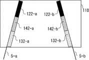
- FIG. 3shows the distance from the vehicle 1 to the object in the first embodiment of the vehicle display device 4 shown in FIG. 2 and the correspondence between the clear region 120 and the blurred region 130.
- the dividing line 5is detected as an object is shown.
- the demarcation line 5is installed on the left and right of the vehicle 1 to delimit the lane.
- ais referred to as an object on the left side of the vehicle 1 (x-axis positive direction) and b is referred to as an object on the right side of the vehicle 1 (x-axis negative direction).
- the dividing line 5is called a dividing line 5-a that means the dividing line 5 on the left side of the vehicle 1 and a dividing line 5-b that means the dividing line 5 on the right side of the vehicle 1.
- the target object information acquisition unit 300acquires target object information of the dividing line 5 which is the target object, and outputs the target object information to the image generation unit 100. From the object information, the image generation unit 100 is less than the first reference value D1 with the object 320 whose distance from the vehicle 1 to the dividing line 5 which is the object is equal to or greater than the first reference value D1. Object 330 is identified.
- the distance from the vehicle 1 to the objectmay be determined based on only the z-axis direction, or a combination of the z-axis direction and the x-axis direction or the y-axis direction, the x-axis direction, the y-axis direction, The z-axis direction may be synthesized as a reference.
- the distance a from the vehicle 1 to the object on the left sideis Add b to the distance up to
- the first reference value D1-awhich means that the distance from the vehicle 1 to the object on the left side is the first reference value D1
- the distance from the vehicle 1 to the object on the right sideis the first reference value It is called a first reference value D1-b, which means that it is D1.
- an area where the object 320 existsis referred to as a sharp area 120
- an area where the object 330 existsis referred to as a blurred area 130.
- the clear area on the left side (x-axis positive direction) of the vehicle 1 and the unsharp area a in the clear area on the right side (x-axis negative direction) of the vehicle 1We call it by adding b.
- the clear area 120is referred to as a clear area 120-a meaning the clear area 120 on the left side of the vehicle 1, and a clear area 120-b meaning the clear area 120 on the right side of the vehicle 1.
- FIG. 4shows a display example of information image superposition in the first embodiment of the vehicle display device shown in FIG.
- the information images 121 and 131are superimposed on the dividing line 5.
- ais referred to as an information image on the left side (x-axis positive direction) of the vehicle 1 and b is referred to as an information image on the right side (x-axis negative direction).
- the information image 121is referred to as an information image 121-a meaning the information image 121 on the left side of the vehicle 1 and a clear area 121-b meaning the information image 121 on the right side of the vehicle 1.
- the image generation unit 100generates the information image 121 of the object 320 in the clear area 120 and the information image 131 of the object 330 in the blurred area 130.
- the information image 131 of the blurred region 130is generated more blurred than the information image 121 of the sharp region 120.
- the clear and unclear expression of the information imageis, for example, the density of the color of the information image, the information image 121 of the clear area 120 is generated to be darker, and the information image 131 of the unsharp area 130 is generated to be lighter.
- the passenger 3becomes more aware of the information image 121 of the clear region 120 than the information image 131 of the blur region 130, and can reliably recognize a distant object (for example, the shape of a parting line or a lane).
- a distant objectfor example, the shape of a parting line or a lane.
- FIG. 5shows another example related to the expression of sharpness and blurring of the information image in the first embodiment of the vehicle display device shown in FIG.
- the lighting of the LED (Light Emitting Diode) of the liquid crystal panel moduleis represented by a black point, and it is possible to express clearness or blur by the brightness of the information image.
- the brightness of the information imagemay be controlled by causing the LED to blink periodically as in the duty (Duty) drive, shifting the position where the light amount is maximum to a clear area, etc. using an actuator and a rotating shaft (not shown). Also good.
- the density of the stripes of the information imagemay be expressed as coarseness, sharpness and blurring.
- the object informationmay be used to display a color close to the object (real scenery).
- FIG. 6is a view showing the correspondence between the distance from the vehicle to the object, the clear region, and the blur region when the speed of the vehicle in the first embodiment of the vehicle display device shown in FIG. 2 is larger than FIG. is there.
- the vehicle information acquisition unit 200acquires the speed of the vehicle 1 and outputs the speed to the image generation unit 100.
- the image generation unit 100increases the first reference value D1 as the speed of the vehicle 1 increases. Since the speed of the vehicle 1 is larger than that in FIG. 4, the first reference value D1 is large, the clear area 120 is small, and the blur area 130 is large.
- FIG. 7is a display example when the speed of the vehicle 1 in the first embodiment of the vehicle display device 4 shown in FIG. 2 is larger than FIG.
- the image generation unit 100generates the information image 121 of the object 320 in the clear area 120 and the information image 131 of the object 330 in the blurred area 130.
- the passenger 3can simultaneously adjust the viewpoint to the far place. This corresponds to the gaze behavior when the vehicle is traveling at high speed, and is felt as a natural information presentation for the passenger 3.
- FIG. 8is a display example when the viewpoint of the passenger 3 in the first embodiment of the vehicle display device 4 shown in FIG. 2 is in the vicinity of the vehicle 1.
- the gaze detection unit 400captures an image of the passenger 3 to detect the gaze and the viewpoint, and outputs the detected gaze to the image generation unit 100.
- the image generation unit 100determines that the distance from the vehicle 1 to the viewpoint of the passenger 3 is the first reference value D1.
- the information image 131 of the unclear region 130is generated more unclearly.
- the image generation unit 100generates a lighter color density of the information image 131.
- the distancemay be a combination of the x-axis direction, the y-axis direction, and the z-axis direction, based on only the z-axis direction or a combination of the z-axis direction and the x-axis direction or the y-axis direction. It may be based on
- the passenger 3looks at the information image 121 of the clear region 120 more than the information image 131 of the blur region 130 where the degree of blur is larger, and the distant object (for example, the shape of the dividing line or lane) It can be recognized more reliably.
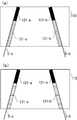
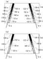
- FIG. 9is a view showing the distance from the vehicle 1 to the object and the correspondence between the clear region 120 and the blur region 130 in the second embodiment of the vehicle display device 4 shown in FIG.
- the first reference value D1is equal to or greater than the second reference value D2.
- the configurationis the same as that of the first embodiment of the display device 4 for a vehicle.
- the target object information acquisition unit 300acquires target object information of the dividing line 5 which is the target object, and outputs the target object information to the image generation unit 100.
- the image generation unit 100determines from the object information that the distance from the vehicle 1 to the dividing line 5 which is the object is the object 320 having the first reference value D1 or more and the object 340 having the second reference value D2 or less. And. Further, it is desirable that the image generation unit 100 also identify an object 350 having a second reference value D2 or more and less than the first reference value D1.
- the distance from the vehicle 1 to the objectmay be determined based on only the z-axis direction, or a combination of the z-axis direction and the x-axis direction or the y-axis direction, the x-axis direction, the y-axis direction,
- the z-axis directionmay be synthesized as a reference.
- the image generation unit 100sets the area where the object 320 exists as the clear area 120 and the area where the object 330 exists as the blurred area 130. Further, a region where the object 350 exists is, for example, an intermediate region 140.
- ais referred to as an intermediate region on the left side (x-axis positive direction) of the vehicle 1 and b is referred to as an intermediate region on the right side (x-axis negative direction).
- the middle area 140is referred to as a middle area 140-a meaning the middle area 140 on the left side of the vehicle 1, and a middle area 140-b meaning the middle area 140 on the right side of the vehicle 1.
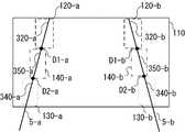
- FIG. 10is a display example of information image superposition in the second embodiment of the vehicular display device 4 shown in FIG.
- the image generation unit 100generates the information image 122 of the object 320 in the clear area 120 and the information image 132 of the object 340 in the blurred area 130. Further, the information image 142 of the object 350 is generated in the intermediate area 140.
- the information image 132 of the blurred area 130is generated more blurred than the information image 122 of the sharp area 120. It is desirable that the information image 142 of the intermediate region 140 be generated more clearly than the information image 132 of the blurred region 130 and more blurred than the information image 122 of the sharp region 120.
- the passenger 3becomes more aware of the information image 132 of the blurred area 130 and the information image 122 of the sharp area 120 than the information image 142 of the intermediate area 140, and reliably recognizes the shape of the dividing line (lane) far away. be able to.
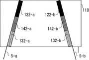
- FIG. 11shows another example regarding the expression of sharpness and blurring of the information image in the second embodiment of the vehicle display device shown in FIG. That is, as shown in FIG. 11 (a), the clearness and the unsharpness may be expressed by the contrast of the brightness of the information image, or as shown in FIG. 11 (b). Alternatively, as shown in FIG. 11C, the density of stripes of the information image may be expressed, and the line width may be wide, narrow, clear, or unclear.
- the vehicle information acquisition unit 200acquires the speed of the vehicle 1 and outputs the speed to the image generation unit 100.
- the image generation unit 100increases the first reference value D1 and the second reference value D2 as the speed of the vehicle 1 increases.
- the first reference value D1becomes larger, and the clear area 120 becomes smaller.
- the second reference value D2becomes large, and the blur region 130 becomes large.
- the first reference value D1 and the second reference value D2become large, the clear area 120 becomes small, and the blurred area 130 becomes large.
- FIG. 13is a display example when the speed of the vehicle 1 in the second embodiment of the vehicle display device 4 shown in FIG. 2 is larger than FIG.
- the image generator 100generates the information image 122 of the object 320 in the clear area 120 and the information image 132 of the object 340 in the blurred area 130. Further, the image generation unit 100 generates an information image 142 of the object 350 in the intermediate region 140.
- the passenger 3can simultaneously adjust the viewpoint to the far place. This corresponds to the gaze behavior when the vehicle is traveling at high speed, and is felt as a natural information presentation for the passenger 3.
- FIG. 14is a display example when the viewpoint of the passenger 3 in the second embodiment of the vehicle display device shown in FIG. 2 is in the vicinity of the vehicle 1.
- the gaze detection unit 400captures an image of the passenger 3 to detect the gaze and the viewpoint, and outputs the detected gaze to the image generation unit 100.
- the image generation unit 100determines that the distance from the vehicle 1 to the viewpoint of the passenger 3 is the first reference value D1 or more
- the information image 132 of the blurred area 130is more blurred.
- the image generation unit 100generates a lighter color density of the information image 132.
- the information image 142 of the intermediate area 140may be generated more unclearly. It is desirable that the information image 142 of the intermediate region 140 be generated more clearly than the information image 132 of the blurred region 130 and more blurred than the information image 122 of the sharp region 120.
- the distancemay be a combination of the x-axis direction, the y-axis direction, and the z-axis direction, based on only the z-axis direction or a combination of the z-axis direction and the x-axis direction or the y-axis direction. It may be based on
- the passenger 3looks at the information image 121 of the clear region 120 more than the information image 131 of the blur region 130 where the degree of blur is larger, and the distant object (for example, the shape of the dividing line or lane) It can be recognized more reliably.
- FIGS. 15 (a) to 15 (b)are other display examples of information image superposition in the second embodiment of the vehicular display device 4 shown in FIG.
- a plurality of intermediate regions 150, 160, 170may be provided between the sharp region 120 and the blurred region 130, and the information image 122, 132, 152, 162, 172 may be generated. .
- FIGS. 16 (a) to 16 (b)are display examples of pedestrian detection in the vehicle display device 4 shown in FIG.
- FIG. 16Ashows an example in the case where the pedestrian 6 is detected as a target at a certain time and in the distance of the vehicle 1.
- the object information acquisition unit 300acquires the object information of the pedestrian 6 that is the object, and outputs the object information to the image generation unit 100.
- the image generation unit 100identifies, from the object information, an object 326 in which the distance from the vehicle 1 to the object is equal to or greater than a first reference value D1.
- the image generation unit 100sets the area where the object 326 is present as the clear area 120 and generates the information image 123 of the object 326 in the clear area 120.
- FIG. 16 (b)shows an example in which the pedestrian 6 is detected as a target object in the vicinity of the vehicle 1 as the vehicle 1 advances or the pedestrian 6 walks after a predetermined time has elapsed from the time.
- the target object information acquisition unit 300acquires target object information of the pedestrian 6 that is the target object, and outputs the target object information to the image generation unit 100. From the object information, the image generation unit 100 outputs, to the image generation unit 100, an object 336 in which the distance from the vehicle 1 to the object is less than the first reference value D1 from the vehicle 1 to the object. Do. In the display area 110 of the display image M, the image generation unit 100 sets the area where the object 336 exists as the blurred area 130 and generates the information image 133 of the object 336 in the blurred area 130.
- the passenger 3can surely recognize the pedestrian 6 who is far away, and the distance becomes short with the lapse of time, and the pedestrian 6 whose visibility becomes easy does not feel annoyance due to excessive information presentation. It is
- FIG. 17is a display example of the direction indication in the vehicular display device 4 shown in FIG. 2, and shows an example in the case where the dividing line 5 and the intersection 7 are detected as an object.
- the object information acquisition unit 300acquires the object information of the dividing line 5 and the intersection 7 which are the objects, and outputs the object information to the image generation unit 100 .
- the image generation unit 100determines, from the object information, an object 325, 327 having a first reference value D1 or more and an object 335 having a second reference value D2 less than the first reference value D1, and a second The target object 345 having the reference value D2 or more and the first reference value D1 or less is output to the image generation unit 100.
- the image generation unit 100sets the area where the objects 325 and 327 exist as the sharp area 120, the area where the object 335 exists as the blurred area 130, and the area where the object 345 exists. Is an intermediate region 140.
- the image generation unit 100generates the information image 124 of the object 325, 327 in the clear area 120, the information image 134 of the object 335 in the blurred area 130, and the information image 146 of the object 345 in the intermediate area 140.
- the passenger 3can surely recognize the intersection 7 located far away, and can easily feel the route to the intersection 7 in accordance with the real scenery.
- the distance from the vehicle 1 to the objectis the first reference value D1 or more, less than the first reference value D1, and less than the second reference value D2, the distance from the vehicle 1 to the object The same effect can be obtained as the first reference value D1 is larger than the first reference value D1 and the second reference value D2 is not larger than the first reference value D1.
- the speed of the vehicle 1 and the speed of the objectmay be taken into consideration, and the arrival time of the vehicle 1 to the object may be used as the reference value .
- the sharp area 120 and the blurred area 130are represented as rectangles in the above embodiment, they may be represented along another figure such as a circle or the outline of an object.
- the display unit 10may display another information image on the display image M in addition to the above information image.
- the speed of the vehicle 1 or the likeFor example, the speed of the vehicle 1 or the like.
- the windshield type HUD apparatuswas used as one form of the display apparatus 4 for vehicles, it is applicable also to a combiner type HUD apparatus.
- the above embodimentis also applicable to a display device such as a head mounted display including a smart glass.
Landscapes
- Engineering & Computer Science (AREA)
- Physics & Mathematics (AREA)
- Transportation (AREA)
- Mechanical Engineering (AREA)
- Chemical & Material Sciences (AREA)
- Combustion & Propulsion (AREA)
- General Physics & Mathematics (AREA)
- Theoretical Computer Science (AREA)
- Multimedia (AREA)
- Optics & Photonics (AREA)
- Instrument Panels (AREA)
- Traffic Control Systems (AREA)
- Controls And Circuits For Display Device (AREA)
Abstract
Description
Translated fromJapanese本発明は、車両用表示装置に関する。The present invention relates to a display device for a vehicle.
車両用表示装置として、車両のウインドシールド等の透光部材に表示画像を投影することによって、ウインドシールドで反射される表示画像の光を用いて運転席に座った搭乗者に、虚像を視認させる、いわゆるヘッドアップディスプレイ(HUD: Head Up Display)装置がある。
例えば、特許文献1に開示される画像処理装置は、走行路に設けられた区画線の車両に対する相対位置を検知し、所定の表示要素である接近表示要素、及び非接近表示要素が、区画線と重畳して視認されるように表示画像を生成し、ウインドシールドに投影していた。As a display device for a vehicle, by projecting a display image on a light transmitting member such as a windshield of a vehicle, a virtual image is made visible to a passenger sitting in a driver's seat using light of the display image reflected by the windshield There is a so-called head up display (HUD) device.
For example, the image processing device disclosed in
車両の近傍にある検知対象物は搭乗者による視認が容易であり、車両の遠方の検知対象物は視認できない、あるいは視認しづらい。すなわち、車両近傍にある検知対象物に関する情報の重要度は低く、車両遠方の対象物に関する情報の重要度は高いと言える。The detection target in the vicinity of the vehicle is easy for the passenger to visually recognize, and the detection target at a distance of the vehicle can not be visually recognized or is difficult to visually recognize. That is, it can be said that the degree of importance of the information on the detection object in the vicinity of the vehicle is low, and the degree of importance of the information on the object distant from the vehicle is high.
しかしながら、上記特許文献1に記載の構成では、車両の近傍と遠方で虚像の表現に差がないため搭乗者は何処に視線を向ければよいか分からず、視認しづらい重要な情報を認識することが困難であった。However, in the configuration described in
本発明は、視認しづらい重要な情報をより確実に搭乗者に認識させることができる車両用表示装置を提供することを目的とする。An object of the present invention is to provide a display device for a vehicle which can make a passenger more surely recognize important information which is difficult to view.
本発明の第1の観点に係る車両用表示装置は、
表示画像を表示する表示部と、
車両用表示装置が搭載される車両の周囲に存在する対象物に関する対象物情報を取得する対象物情報取得部と、
前記表示画像を生成する画像生成部と、
を備え、
前記表示画像の表示領域は、鮮明領域と不鮮明領域を備え、
前記画像生成部は、前記車両から前記対象物までの距離が第一の基準値以上、若しくはより大きい場合は前記対象物の情報画像を前記鮮明領域に生成し、前記車両から前記対象物までの前記距離が前記第一の基準値未満、若しくは以下の場合は前記対象物の前記情報画像を前記不鮮明領域に生成し、
前記不鮮明領域の前記情報画像は、前記鮮明領域の前記情報画像よりも不鮮明に生成される、
ことを特徴とする。A display device for a vehicle according to a first aspect of the present invention is:
A display unit for displaying a display image;
An object information acquisition unit that acquires object information on an object present around a vehicle on which the display device for a vehicle is mounted;
An image generation unit that generates the display image;
Equipped with
The display area of the display image comprises a sharp area and a blurred area,
The image generation unit generates an information image of the object in the clear area when the distance from the vehicle to the object is equal to or larger than a first reference value, or from the vehicle to the object. Generating the information image of the object in the blurred region if the distance is less than or equal to the first reference value;
The information image of the blurred region is generated more blurred than the information image of the sharp region.
It is characterized by
本発明の第2の観点に係る車両用表示装置は、
表示画像を表示する表示部と、
車両用表示装置が搭載される車両の周囲に存在する対象物に関する対象物情報を取得する対象物情報取得部と、
前記表示画像を生成する画像生成部と、
を備え、
前記表示画像の表示領域は、鮮明領域と不鮮明領域を備え、
前記画像生成部は、前記車両から前記対象物までの距離が第一の基準値以上、若しくはより大きい場合は前記対象物の情報画像を前記鮮明領域に生成し、前記車両から前記対象物までの前記距離が第二の基準値未満、若しくは、以下の場合は前記対象物の前記情報画像を前記不鮮明領域に生成し、
前記不鮮明領域の前記情報画像は、前記鮮明領域の前記情報画像よりも不鮮明に生成され、
前記第一の基準値は、前記第二の基準値以上である、
ことを特徴とする。A display device for a vehicle according to a second aspect of the present invention is:
A display unit for displaying a display image;
An object information acquisition unit that acquires object information on an object present around a vehicle on which the display device for a vehicle is mounted;
An image generation unit that generates the display image;
Equipped with
The display area of the display image comprises a sharp area and a blurred area,
The image generation unit generates an information image of the object in the clear area when the distance from the vehicle to the object is equal to or larger than a first reference value, or from the vehicle to the object. Generating the information image of the object in the blurred region if the distance is less than a second reference value or
The information image of the blurred region is generated more blurred than the information image of the sharp region;
The first reference value is equal to or greater than the second reference value.
It is characterized by
本発明によれば、視認しづらい重要な情報を確実に搭乗者に認識させることができる。According to the present invention, it is possible to ensure that the passenger can recognize important information that is difficult to view.
以下に説明する好ましい実施形態は、本発明を容易に理解するために用いられている。従って、当業者は、本発明が、以下に説明される実施形態によって不当に限定されないことを留意すべきである。The preferred embodiments described below are used to facilitate understanding of the present invention. Accordingly, one of ordinary skill in the art should note that the present invention is not unduly limited by the embodiments described below.
図1には、車両用表示装置4の一形態であるヘッドアップディスプレイ装置(以下、HUD装置ともいう)8の構成の概略図が示されている。HUD装置8は、表示部10と、平面ミラー21と、曲面ミラー22と、筐体30と、を備え、筐体30はケース31と透明カバー32からなる。HUD装置8は、表示部10が表示した表示画像Mを表す表示光Lを、平面ミラー21と曲面ミラー22とで反射させ、HUD装置8が搭載される車両1の透光部材からなるウインドシールド2に出射し、搭乗者3(通常、車両1の運転者)に、実風景に重畳するように虚像Vを視認させるものである。HUD装置8がこのように表示する内容は、各種車両情報、ナビゲーション情報、拡張現実(AR: Augmented Reality)情報等である。また、図1に示されている座標軸において、z軸正方向は車両1の前方向を表し、y軸正方向は鉛直方向上側を表し、x軸正方向(図面に対して垂直上方向)は車両1の左方向を表す。FIG. 1 shows a schematic view of the configuration of a head-up display device (hereinafter also referred to as a HUD device) 8 which is an embodiment of a
図2には、車両用表示装置4のブロック図が示されている。車両用表示装置4は、表示部10、画像生成部100、車両情報取得部200、対象物情報取得部300、視線検出部400を備えている。The block diagram of the
表示部10は、液晶パネルモジュールからなり、画像生成部100が生成した表示画像Mを表示する。なお、他の実施例として、有機EL(Electro Luminescence)素子等の自発光表示パネルモジュールであってもよく、DMD(Digital Micromirror Device)、LCoS(Liquid Crystal on Silicon)(登録商標)等の反射型表示パネルモジュールであってもよく、レーザー光を走査する走査型表示装置等であってもよい。The
画像生成部100は、回路で構成され、前記回路は少なくとも1つのプロセッサ(例えば、中央処理装置(CPU: Central Processing Unit))、少なくとも1つの特定用途向け集積回路(ASIC: Application Specific Integrated Circuit)、および/または、少なくとも1つのフィールドプログラマブルゲートアレイ(FPGA: Field-Programmable Gate Array)などの少なくとも1つの半導体集積回路を含む。少なくとも1つのプロセッサは、少なくとも1つのコンピュータ読み取り可能で有形な記録媒体から1つまたは複数の命令を読み取ることにより、図2に示す車両用表示装置4の機能の全部または一部を実行することができる。前記記録媒体は、ハードディスクのような任意のタイプの磁気媒体、CDおよびDVDのような任意のタイプの光学媒体、揮発性メモリのような任意のタイプの半導体メモリ、および不揮発性メモリを含む。揮発性メモリはDRAM及びSRAMを含み、不揮発性メモリはROM及びNVRAMを含む。半導体メモリは、少なくとも1つのプロセッサと共に回路の一部となる半導体回路でもある。ASICは、図2に示す車両用表示装置4の機能の全部または一部を実行するようにカスタマイズされた集積回路であり、FPGAは、製造後に、図2に示す車両用表示装置4の機能の全部または一部を実行できるように設計された集積回路である。画像生成部100は、車両情報取得部200、対象物情報取得部300、視線検出部400からの情報を基に画像処理を行い、少なくとも1つの情報画像を備えた表示画像Mを生成する。前記情報画像は、例えば、実風景に情報を付加するためのAR画像である。The
車両情報取得部200は、少なくとも車両1の速度を検出し、その検出結果を図示しないCAN(Control Area Network)などの通信インターフェースを介して車両用表示装置4の画像生成部100に出力する。なお、他の実施例として、GPS(Global Positioning System)を含むGNSS(Global Navigation Satellite System)等の図示しない位置情報取得手段を備え、車両1の位置情報の推移から車両1の速度を推定し、この推定した速度を車両用表示装置4の画像生成部100に出力するものであってもよい。The vehicle
対象物情報取得部300は、ステレオカメラや単眼カメラから構成され、車両1の周囲、少なくとも前方、を撮影し、撮影した画像データを解析して車両1周囲の対象物に関する対象物情報(区画線、停止線、交差点、カーブ、横断歩道、歩行者、他の車両、位置、大きさ、色、車両1との距離、車両1との相対速度等)を取得し、車両用表示装置4の画像生成部100に出力する。なお、他の実施例として、LIDAR(Light Detection and Ranging)等のリモートセンシングや、V2X(Vehicle to X)等の車車間通信、路車間通信から車両1周囲の対象物に関する前記対象物情報を取得し、車両用表示装置4の画像生成部100に出力するものであってもよい。The object
視線検出部400は、ステレオカメラや単眼カメラから構成され、搭乗者3を撮影して視線、及び視点を検出し、車両用表示装置4の画像生成部100に出力する。The line-of-
図3には、図2に示される車両用表示装置4の第1の実施形態における車両1から対象物までの距離と鮮明領域120、及び不鮮明領域130の対応が示されている。ここでは、区画線5を対象物として検知した場合の例を示す。FIG. 3 shows the distance from the
通常、区画線5は車線を区切るために車両1の左右に設置されている。以後、対象物の左右を区別するため、車両1の左側(x軸正方向)の対象物についてaを、車両1の右側(x軸負方向)の対象物についてbを付加して呼ぶ。例えば、区画線5について、車両1の左側の区画線5を意味する区画線5-a、車両1の右側の区画線5を意味する区画線5-b、と呼ぶ。Normally, the
対象物情報取得部300は、対象物である区画線5の対象物情報を取得し、画像生成部100に出力する。画像生成部100は、前記対象物情報から、車両1から対象物である区画線5までの距離が第一の基準値D1以上である対象物320と、及び第一の基準値D1未満である対象物330と、を識別する。前記車両1から対象物までの距離は、z軸方向のみを基準としても、z軸方向とx軸方向、またはy軸方向を合成したものを基準としても、x軸方向、y軸方向、及びz軸方向を合成したものを基準としてもよい。以後、車両1から対象物までの距離の左右を区別するため、車両1から左側(x軸正方向)の対象物までの距離についてaを、車両1から右側(x軸負方向)の対象物までの距離についてbを付加して呼ぶ。例えば、車両1から左側の対象物までの距離が第一の基準値D1であることを意味する第一の基準値D1-a、車両1から右側の対象物までの距離が第一の基準値D1であることを意味する第一の基準値D1-b、と呼ぶ。The target object
表示画像Mの表示領域110において、対象物320が存在する領域を鮮明領域120、対象物330が存在する領域を不鮮明領域130とする。以後、鮮明領域、不鮮明領域の左右を区別するため、車両1の左側(x軸正方向)の鮮明領域、不鮮明領域についてaを、車両1の右側(x軸負方向)の鮮明領域、不鮮明領域についてbを付加して呼ぶ。例えば、鮮明領域120について、車両1の左側の鮮明領域120を意味する鮮明領域120-a、車両1の右側の鮮明領域120を意味する鮮明領域120-b、と呼ぶ。In the
図4は、図2に示される車両用表示装置の第1の実施形態における情報画像重畳の表示例が示されている。図4では、区画線5に情報画像121,131を重畳している。以後、情報画像の左右を区別するため、車両1の左側(x軸正方向)の情報画像についてaを、車両1の右側(x軸負方向)の情報画像についてbを付加して呼ぶ。例えば、情報画像121について、車両1の左側の情報画像121を意味する情報画像121-a、車両1の右側の情報画像121を意味する鮮明領域121-b、と呼ぶ。FIG. 4 shows a display example of information image superposition in the first embodiment of the vehicle display device shown in FIG. In FIG. 4, the
画像生成部100は、対象物320の情報画像121を鮮明領域120に、及び対象物330の情報画像131を不鮮明領域130に生成する。不鮮明領域130の情報画像131は、鮮明領域120の情報画像121よりも、不鮮明に生成される。The
情報画像の鮮明、不鮮明の表現は、例えば、情報画像の色の濃度であり、鮮明領域120の情報画像121は色が濃く生成され、不鮮明領域130の情報画像131は色が薄く生成される。The clear and unclear expression of the information image is, for example, the density of the color of the information image, the
搭乗者3は、不鮮明領域130の情報画像131よりも鮮明領域120の情報画像121を意識するようになり、遠方の対象物(例えば、区画線形状や車線)について確実に認識することができる。The
また、搭乗者3が視認しやすい車両1の近傍の情報画像を不鮮明にすることで、車両1の近傍の情報画像と対象物(実風景)がずれたことによる違和感を小さくできる。Further, by making the information image in the vicinity of the
図5は、図2に示される車両用表示装置の第1の実施形態における情報画像の鮮明、不鮮明の表現に関する他の実施例を示している。図5(a)の様に、例えば、液晶パネルモジュールのLED(Light Emitting Diode)の点灯は黒点で表されており、情報画像の輝度の明暗で鮮明、不鮮明を表現しても良い。あるいは、デューティー(Duty)駆動の様にLEDを周期的に点滅させる、図示しないアクチュエータや回転軸を用いて光量が最大となる位置を鮮明領域にずらす等をして情報画像の輝度を制御しても良い。また、図5(b)の様に情報画像の縞模様の粗密で鮮明、不鮮明を表現しても良い。さらに、縞模様の間隙について、前記対象物情報を用いて対象物(実風景)に近い色を表示しても良い。FIG. 5 shows another example related to the expression of sharpness and blurring of the information image in the first embodiment of the vehicle display device shown in FIG. As shown in FIG. 5A, for example, the lighting of the LED (Light Emitting Diode) of the liquid crystal panel module is represented by a black point, and it is possible to express clearness or blur by the brightness of the information image. Alternatively, the brightness of the information image may be controlled by causing the LED to blink periodically as in the duty (Duty) drive, shifting the position where the light amount is maximum to a clear area, etc. using an actuator and a rotating shaft (not shown). Also good. Further, as shown in FIG. 5 (b), the density of the stripes of the information image may be expressed as coarseness, sharpness and blurring. Furthermore, for the striped gaps, the object information may be used to display a color close to the object (real scenery).
図6は、図2に示される車両用表示装置の第1の実施形態における車両の速度が図3より大きい時の車両から対象物までの距離と鮮明領域、不鮮明領域の対応を示した図である。車両情報取得部200は、車両1の速度を取得し、画像生成部100に出力する。画像生成部100は、車両1の前記速度が大きいほど第一の基準値D1を大きくする。車両1の速度が図4よりも大きいため第一の基準値D1が大きくなり、鮮明領域120は小さく、不鮮明領域130は大きくなる。FIG. 6 is a view showing the correspondence between the distance from the vehicle to the object, the clear region, and the blur region when the speed of the vehicle in the first embodiment of the vehicle display device shown in FIG. 2 is larger than FIG. is there. The vehicle
図7は、図2に示される車両用表示装置4の第1の実施形態における車両1の速度が、図3より大きい時の表示例である。画像生成部100は、対象物320の情報画像121を鮮明領域120に、及び対象物330の情報画像131を不鮮明領域130に生成する。FIG. 7 is a display example when the speed of the
搭乗者3は、不鮮明領域130の情報画像131に対し割合が小さくなった鮮明領域120の情報画像121を確認することにより、同時に遠方に視点を合わせることが出来る。これは、車両で高速走行している時の注視挙動と一致し、搭乗者3にとって自然な情報提示として感じられる。By checking the
図8は、図2に示される車両用表示装置4の第1の実施形態における搭乗者3の視点が、車両1の近傍にある場合の表示例である。視線検出部400は、搭乗者3を撮影して視線、及び視点を検出し、画像生成部100に出力する。画像生成部100は、車両1から搭乗者3の前記視点までの距離が第一の基準値D1未満の場合は、車両1から搭乗者3の前記視点までの前記距離が第一の基準値D1以上の場合と比較して、不鮮明領域130の情報画像131をより不鮮明に生成する。例えば、画像生成部100は、情報画像131の色の濃度をより薄く生成する。前記距離は、z軸方向のみを基準としても、z軸方向とx軸方向、またはy軸方向を合成したものを基準としても、x軸方向、y軸方向、及びz軸方向を合成したものを基準としてもよい。FIG. 8 is a display example when the viewpoint of the
搭乗者3は、不鮮明度がより大きくなった不鮮明領域130の情報画像131よりも鮮明領域120の情報画像121に視線を向けるようになり、遠方の対象物(例えば、区画線形状や車線)についてより確実に認識することができる。The
図9は、図2に示される車両用表示装置4の第2の実施形態における車両1から対象物までの距離と鮮明領域120、不鮮明領域130の対応を示した図である。車両用表示装置4の第2の実施形態において、第一の基準値D1は、第二の基準値D2以上である。第一の基準値D1が第二の基準値D2と等しい場合、車両用表示装置4の第1の実施形態と同様の構成となる。FIG. 9 is a view showing the distance from the
対象物情報取得部300は、対象物である区画線5の対象物情報を取得し、画像生成部100に出力する。画像生成部100は、前記対象物情報から、車両1から対象物である区画線5までの距離が第一の基準値D1以上の対象物320と、第二の基準値D2未満の対象物340と、を識別する。また、画像生成部100は、第二の基準値D2以上、且つ第一の基準値D1未満の対象物350についても識別することが望ましい。前記車両1から対象物までの距離は、z軸方向のみを基準としても、z軸方向とx軸方向、またはy軸方向を合成したものを基準としても、x軸方向、y軸方向、及びz軸方向を合成したものを基準としてもよい。The target object
画像生成部100は、表示画像Mの表示領域110について、対象物320が存在する領域を鮮明領域120と、対象物330が存在する領域を不鮮明領域130とする。また、対象物350が存在する領域を、例えば、中間領域140とする。以後、中間領域の左右を区別するため、車両1の左側(x軸正方向)の中間領域についてaを、車両1の右側(x軸負方向)の中間領域についてbを付加して呼ぶ。例えば、中間領域140について、車両1の左側の中間領域140を意味する中間領域140-a、車両1の右側の中間領域140を意味する中間領域140-b、と呼ぶ。In the
図10は、図2に示される車両用表示装置4の第2の実施形態における情報画像重畳の表示例である。画像生成部100は、対象物320の情報画像122を鮮明領域120に、対象物340の情報画像132を不鮮明領域130に生成する。また、対象物350の情報画像142を中間領域140に生成する。不鮮明領域130の情報画像132は、鮮明領域120の情報画像122よりも、不鮮明に生成される。中間領域140の情報画像142は、不鮮明領域130の情報画像132よりも鮮明、且つ鮮明領域120の情報画像122よりも不鮮明に生成されることが望ましい。FIG. 10 is a display example of information image superposition in the second embodiment of the
搭乗者3は、不鮮明領域130の情報画像132、及び中間領域140の情報画像142よりも鮮明領域120の情報画像122を意識するようになり、遠方の区画線形状(車線)について確実に認識することができる。The
図11は、図2に示される車両用表示装置の第2の実施形態における情報画像の鮮明、不鮮明の表現に関する他の実施例を示している。すなわち、図11(a)の様に情報画像の輝度の明暗で鮮明、不鮮明を表現しても良いし、図11(b)の様に情報画像の縞模様の粗密で鮮明、不鮮明を表現しても良いし、図11(c)の様に情報画像の縞模様の粗密、及び線幅の広狭で鮮明、不鮮明を表現しても良い。FIG. 11 shows another example regarding the expression of sharpness and blurring of the information image in the second embodiment of the vehicle display device shown in FIG. That is, as shown in FIG. 11 (a), the clearness and the unsharpness may be expressed by the contrast of the brightness of the information image, or as shown in FIG. 11 (b). Alternatively, as shown in FIG. 11C, the density of stripes of the information image may be expressed, and the line width may be wide, narrow, clear, or unclear.
図12(a)乃至(c)は、図2に示される車両用表示装置4の第2の実施形態における車両1の速度が図9より大きい時の車両から対象物までの距離と鮮明領域、不鮮明領域の対応を示した図である。車両情報取得部200は、車両1の速度を取得し、画像生成部100に出力する。画像生成部100は、車両1の前記速度が大きいほど第一の基準値D1、及び第二の基準値D2を大きくする。図12(a)では、車両1の速度が図9よりも大きいため第一の基準値D1が大きくなり、鮮明領域120は小さくなる。図12(b)では、車両1の速度が図9よりも大きいため第二の基準値D2が大きくなり、不鮮明領域130は大きくなる。図12(c)では、車両1の速度が図9よりも大きいため第一の基準値D1、及び第二の基準値D2が大きくなり、鮮明領域120は小さく、且つ不鮮明領域130は大きくなる。12 (a) to 12 (c) show the distance from the vehicle to the object and the clear region when the speed of the
図13は、図2に示される車両用表示装置4の第2の実施形態における車両1の速度が、図9より大きい時の表示例である。画像生成部100は、対象物320の情報画像122を鮮明領域120に、及び対象物340の情報画像132を不鮮明領域130に生成する。また、画像生成部100は、対象物350の情報画像142を中間領域140に生成する。FIG. 13 is a display example when the speed of the
搭乗者3は、不鮮明領域130の情報画像132に対し割合が小さくなった鮮明領域120の情報画像122を確認することにより、同時に遠方に視点を合わせることが出来る。これは、車両で高速走行している時の注視挙動と一致し、搭乗者3にとって自然な情報提示として感じられる。By checking the
図14は、図2に示される車両用表示装置の第2の実施形態における搭乗者3の視点が車両1近傍にある場合の表示例である。視線検出部400は、搭乗者3を撮影して視線、及び視点を検出し、画像生成部100に出力する。画像生成部100は、車両1から搭乗者3の前記視点までの距離が第一の基準値D1未満の場合は、車両1から搭乗者3の前記視点までの距離が第一の基準値D1以上の場合と比較して、不鮮明領域130の情報画像132をより不鮮明に生成する。例えば、画像生成部100は、情報画像132の色の濃度をより薄く生成する。このとき、中間領域140の情報画像142についてもより不鮮明に生成してよい。中間領域140の情報画像142は、不鮮明領域130の情報画像132よりも鮮明、且つ鮮明領域120の情報画像122よりも不鮮明に生成されることが望ましい。前記距離は、z軸方向のみを基準としても、z軸方向とx軸方向、またはy軸方向を合成したものを基準としても、x軸方向、y軸方向、及びz軸方向を合成したものを基準としてもよい。FIG. 14 is a display example when the viewpoint of the
搭乗者3は、不鮮明度がより大きくなった不鮮明領域130の情報画像131よりも鮮明領域120の情報画像121に視線を向けるようになり、遠方の対象物(例えば、区画線形状や車線)についてより確実に認識することができる。The
図15(a)乃至(b)は、図2に示される車両用表示装置4の第2の実施形態における情報画像重畳の別の表示例である。FIGS. 15 (a) to 15 (b) are other display examples of information image superposition in the second embodiment of the
図15(a)に示されるように、鮮明領域120と不鮮明領域130の間に複数の中間領域150,160,170を備え、情報画像122,132,152,162,172を生成しても良い。As shown in FIG. 15A, a plurality of
また、図15(b)に示されるように、鮮明領域120の情報画像122と不鮮明領域130の情報画像132を、中間領域140の情報画像142で鮮明、不鮮明の表現を滑らかに接続しても良い。Further, as shown in FIG. 15B, even if the
図16(a)乃至(b)は、図2に示される車両用表示装置4における歩行者検知の表示例である。FIGS. 16 (a) to 16 (b) are display examples of pedestrian detection in the
図16(a)は、ある時刻に歩行者6を対象物として車両1の遠方に検知した場合の例を示す。車両用表示装置4の第1の実施形態を用いた場合、対象物情報取得部300は、対象物である歩行者6の対象物情報を取得し、画像生成部100に出力する。画像生成部100は、前記対象物情報から、車両1から前記対象物までの距離が第一の基準値D1以上の対象物326を識別する。画像生成部100は、表示画像Mの表示領域110について、対象物326が存在する領域を鮮明領域120とし、対象物326の情報画像123を鮮明領域120に生成する。FIG. 16A shows an example in the case where the
図16(b)は、前記時刻から一定時間経過し、車両1が前進した、あるいは、歩行者6が歩行したことにより、歩行者6を対象物として車両1の近傍に検知した場合の例を示す。対象物情報取得部300は、対象物である歩行者6の対象物情報を取得し、画像生成部100に出力する。画像生成部100は、前記対象物情報から、車両1から前記対象物までの距離が車両1から前記対象物までの距離が第一の基準値D1未満の対象物336を画像生成部100に出力する。画像生成部100は、表示画像Mの表示領域110について、対象物336が存在する領域を不鮮明領域130とし、対象物336の情報画像133を不鮮明領域130に生成する。FIG. 16 (b) shows an example in which the
搭乗者3は、遠方にいる歩行者6を確実に認識することができ、且つ時間経過とともに距離が近くなり、視認が容易となった歩行者6について、過度な情報提示によるわずらわしさを感じずに済む。The
図17は、図2に示される車両用表示装置4における方向指示の表示例であり、区画線5、及び交差点7を対象物として検知した場合の例を示す。車両用表示装置4の第2の実施形態を用いた場合、対象物情報取得部300は、対象物である区画線5、及び交差点7の対象物情報を取得し、画像生成部100に出力する。画像生成部100は、前記対象物情報から、車両1から前記対象物までの距離が第一の基準値D1以上の対象物325,327、第二の基準値D2未満の対象物335、第二の基準値D2以上、且つ第一の基準値D1未満の対象物345について画像生成部100に出力する。画像生成部100は、表示画像Mの表示領域110について、対象物325,327が存在する領域を鮮明領域120とし、対象物335が存在する領域を不鮮明領域130とし、対象物345が存在する領域を中間領域140とする。画像生成部100は、対象物325,327の情報画像124を鮮明領域120に、対象物335の情報画像134を不鮮明領域130に、対象物345の情報画像146を中間領域140に生成する。FIG. 17 is a display example of the direction indication in the
搭乗者3は、遠方にある交差点7を確実に認識することができ、且つ交差点7に至るまでの経路について実風景との一致性を感じやすくなる。The
上記実施形態において、車両1から対象物までの距離が第一の基準値D1以上、第一の基準値D1未満、第二の基準値D2未満、としたが、車両1から対象物までの距離が第一の基準値D1より大きい、第一の基準値D1以下、第二の基準値D2以下、としても同様の効果を得ることが出来る。In the above embodiment, although the distance from the
上記実施形態において、車両1から対象物までの距離を基準値としたが、車両1の速度や対象物の速度を併せて考慮し、車両1の対象物までの到達時間を基準値としても良い。In the above embodiment, although the distance from the
上記実施形態において、鮮明領域120、不鮮明領域130を矩形で表したが、円形等の別の図形や対象物の輪郭に沿って表しても良い。Although the
上記実施形態において、表示部10は、上記情報画像と合わせて別の情報画像も表示画像Mに表示しても良い。例えば、車両1の速度等である。In the above embodiment, the
上記実施形態において、車両用表示装置4の一形態としてウインドシールド型のHUD装置を用いたが、コンバイナ型のHUD装置にも適用可能である。In the said embodiment, although the windshield type HUD apparatus was used as one form of the
上記実施形態は、スマートグラスを含むヘッドマウントディスプレイ(Head Mounted Display)等の表示装置にも適用可能である。The above embodiment is also applicable to a display device such as a head mounted display including a smart glass.
1・・・車両
2・・・ウインドシールド
3・・・搭乗者
4・・・車両用表示装置
5・・・区画線
6・・・歩行者
7・・・交差点
8・・・ヘッドアップディスプレイ装置
10・・・表示部
21・・・平面ミラー
22・・・曲面ミラー
30・・・筐体
100・・・画像生成部
110・・・表示領域
120・・・鮮明領域
121・・・情報画像
130・・・不鮮明領域
131・・・情報画像
140・・・中間領域
142・・・情報画像
200・・・車両情報取得部
300・・・対象物情報取得部
320・・・第一の基準値以上の対象物
330・・・第一の基準値未満の対象物
340・・・第二の基準値未満の対象物
400・・・視線検出部
D1・・・第一の基準値
D2・・・第二の基準値
Claims (8)
Translated fromJapanese車両用表示装置が搭載される車両の周囲に存在する対象物に関する対象物情報を取得する対象物情報取得部と、
前記表示画像を生成する画像生成部と、
を備え、
前記表示画像の表示領域は、鮮明領域と不鮮明領域を備え、
前記画像生成部は、前記車両から前記対象物までの距離が第一の基準値以上、若しくはより大きい場合は前記対象物の情報画像を前記鮮明領域に生成し、前記車両から前記対象物までの前記距離が前記第一の基準値未満、若しくは以下の場合は前記対象物の前記情報画像を前記不鮮明領域に生成し、
前記不鮮明領域の前記情報画像は、前記鮮明領域の前記情報画像よりも不鮮明に生成される、
ことを特徴とする車両用表示装置。A display unit for displaying a display image;
An object information acquisition unit that acquires object information on an object present around a vehicle on which the display device for a vehicle is mounted;
An image generation unit that generates the display image;
Equipped with
The display area of the display image comprises a sharp area and a blurred area,
The image generation unit generates an information image of the object in the clear area when the distance from the vehicle to the object is equal to or larger than a first reference value, or from the vehicle to the object. Generating the information image of the object in the blurred region if the distance is less than or equal to the first reference value;
The information image of the blurred region is generated more blurred than the information image of the sharp region.
And a display device for a vehicle.
前記車両の速度が大きいほど前記第一の基準値を大きくする、
ことを特徴とする請求項1に記載の車両用表示装置。The image generation unit
The first reference value is increased as the speed of the vehicle increases.
A display device for a vehicle according to claim 1, characterized in that.
前記車両から前記車両の搭乗者の視点までの距離が前記第一の基準値未満、若しくは以下の場合に、前記車両から前記車両の前記搭乗者の前記視点までの前記距離が前記第一の基準値以上、若しくはより大きい場合と比較して、前記不鮮明領域の前記情報画像をより不鮮明に生成する、
ことを特徴とする請求項1乃至2のいずれか1つに記載の車両用表示装置。The image generation unit
When the distance from the vehicle to the viewpoint of the passenger of the vehicle is less than or equal to the first reference value, the distance from the vehicle to the viewpoint of the passenger of the vehicle is the first reference Produce the information image of the blurred area more unclearly as compared to the case where the value is larger than or larger than the value,
The display apparatus for vehicles according to any one of claims 1 to 2 characterized by things.
車両用表示装置が搭載される車両の周囲に存在する対象物に関する対象物情報を取得する対象物情報取得部と、
前記表示画像を生成する画像生成部と、
を備え、
前記表示画像の表示領域は、鮮明領域と不鮮明領域を備え、
前記画像生成部は、前記車両から前記対象物までの距離が第一の基準値以上、若しくはより大きい場合は前記対象物の情報画像を前記鮮明領域に生成し、前記車両から前記対象物までの前記距離が第二の基準値未満、若しくは、以下の場合は前記対象物の前記情報画像を前記不鮮明領域に生成し、
前記不鮮明領域の前記情報画像は、前記鮮明領域の前記情報画像よりも不鮮明に生成され、
前記第一の基準値は、前記第二の基準値以上である、
ことを特徴とする車両用表示装置。A display unit for displaying a display image;
An object information acquisition unit that acquires object information on an object present around a vehicle on which the display device for a vehicle is mounted;
An image generation unit that generates the display image;
Equipped with
The display area of the display image comprises a sharp area and a blurred area,
The image generation unit generates an information image of the object in the clear area when the distance from the vehicle to the object is equal to or larger than a first reference value, or from the vehicle to the object. Generating the information image of the object in the blurred region if the distance is less than a second reference value or
The information image of the blurred region is generated more blurred than the information image of the sharp region;
The first reference value is equal to or greater than the second reference value.
And a display device for a vehicle.
前記車両の速度が大きいほど前記第一の基準値を大きくする、
ことを特徴とする請求項4に記載の車両用表示装置。The image generation unit
The first reference value is increased as the speed of the vehicle increases.
The display device for a vehicle according to claim 4,
前記車両の速度が大きいほど前記第二の基準値を大きくする、
ことを特徴とする請求項4に記載の車両用表示装置。The image generation unit
The second reference value is increased as the speed of the vehicle increases.
The display device for a vehicle according to claim 4,
前記車両の速度が大きいほど前記第一の基準値、及び前記第二の基準値を大きくする、
ことを特徴とする請求項4に記載の車両用表示装置。The image generation unit
The first reference value and the second reference value are increased as the speed of the vehicle increases.
The display device for a vehicle according to claim 4,
前記車両から前記車両の搭乗者の視点までの距離が前記第一の基準値未満、若しくは以下の場合に、前記車両から前記車両の前記搭乗者の前記視点までの前記距離が前記第一の基準値以上、若しくは、より大きい場合と比較して、前記不鮮明領域の前記情報画像をより不鮮明に生成する、
ことを特徴とする請求項4乃至7のいずれか1つに記載の車両用表示装置。The image generation unit
When the distance from the vehicle to the viewpoint of the passenger of the vehicle is less than or equal to the first reference value, the distance from the vehicle to the viewpoint of the passenger of the vehicle is the first reference Produce the information image of the blurred area more blurred compared to the case where the value is larger or larger.
A display device for a vehicle according to any one of claims 4 to 7, characterized in that:
Priority Applications (3)
| Application Number | Priority Date | Filing Date | Title |
|---|---|---|---|
| EP18843129.0AEP3666578B1 (en) | 2017-08-10 | 2018-07-30 | Vehicle display device |
| JP2019535114AJP7167918B2 (en) | 2017-08-10 | 2018-07-30 | vehicle display |
| US16/631,028US11170537B2 (en) | 2017-08-10 | 2018-07-30 | Vehicle display device |
Applications Claiming Priority (2)
| Application Number | Priority Date | Filing Date | Title |
|---|---|---|---|
| JP2017155425 | 2017-08-10 | ||
| JP2017-155425 | 2017-08-10 |
Publications (1)
| Publication Number | Publication Date |
|---|---|
| WO2019031291A1true WO2019031291A1 (en) | 2019-02-14 |
Family
ID=65271579
Family Applications (1)
| Application Number | Title | Priority Date | Filing Date |
|---|---|---|---|
| PCT/JP2018/028472CeasedWO2019031291A1 (en) | 2017-08-10 | 2018-07-30 | Vehicle display device |
Country Status (4)
| Country | Link |
|---|---|
| US (1) | US11170537B2 (en) |
| EP (1) | EP3666578B1 (en) |
| JP (1) | JP7167918B2 (en) |
| WO (1) | WO2019031291A1 (en) |
Families Citing this family (3)
| Publication number | Priority date | Publication date | Assignee | Title |
|---|---|---|---|---|
| WO2020159245A1 (en)* | 2019-01-31 | 2020-08-06 | 엘지전자 주식회사 | Method for sharing images between vehicles |
| DE102020211298A1 (en) | 2020-09-09 | 2022-03-10 | Volkswagen Aktiengesellschaft | Method for representing a virtual element |
| DE102022105187B4 (en)* | 2022-03-04 | 2024-06-20 | Audi Aktiengesellschaft | Method for displaying an environment of a vehicle and display system |
Citations (6)
| Publication number | Priority date | Publication date | Assignee | Title |
|---|---|---|---|---|
| JP2008001182A (en)* | 2006-06-21 | 2008-01-10 | Nissan Motor Co Ltd | Visual information presentation device for vehicle and visual information presentation method for vehicle |
| JP2015011666A (en)* | 2013-07-02 | 2015-01-19 | 株式会社デンソー | Head-up display and program |
| JP2015024709A (en)* | 2013-07-25 | 2015-02-05 | 株式会社デンソー | Vehicle user interface system |
| JP2016105256A (en) | 2014-12-01 | 2016-06-09 | 株式会社デンソー | Image processing apparatus |
| WO2017046937A1 (en)* | 2015-09-18 | 2017-03-23 | 日産自動車株式会社 | Display apparatus for vehicle and display method for vehicle |
| JP2017154613A (en)* | 2016-03-02 | 2017-09-07 | トヨタ自動車株式会社 | Display device for vehicle |
Family Cites Families (8)
| Publication number | Priority date | Publication date | Assignee | Title |
|---|---|---|---|---|
| EP2546819B1 (en)* | 2010-04-19 | 2015-06-03 | Honda Motor Co., Ltd. | Device for monitoring vicinity of vehicle |
| JPWO2012067028A1 (en)* | 2010-11-16 | 2014-05-12 | コニカミノルタ株式会社 | Image input device and image processing device |
| JP5582008B2 (en) | 2010-12-08 | 2014-09-03 | トヨタ自動車株式会社 | Vehicle information transmission device |
| JP5942979B2 (en)* | 2013-12-27 | 2016-06-29 | トヨタ自動車株式会社 | Vehicle information display device and vehicle information display method |
| JP6252316B2 (en) | 2014-03-31 | 2017-12-27 | 株式会社デンソー | Display control device for vehicle |
| JP6536855B2 (en) | 2015-09-28 | 2019-07-03 | 日産自動車株式会社 | Display device for vehicle and display method for vehicle |
| JP6860433B2 (en)* | 2017-06-19 | 2021-04-14 | 株式会社東芝 | Processing equipment, processing systems, methods and programs |
| JP6796806B2 (en)* | 2017-06-30 | 2020-12-09 | パナソニックIpマネジメント株式会社 | Display system, information presentation system, display system control method, program, and mobile |
- 2018
- 2018-07-30WOPCT/JP2018/028472patent/WO2019031291A1/ennot_activeCeased
- 2018-07-30USUS16/631,028patent/US11170537B2/enactiveActive
- 2018-07-30EPEP18843129.0Apatent/EP3666578B1/enactiveActive
- 2018-07-30JPJP2019535114Apatent/JP7167918B2/enactiveActive
Patent Citations (6)
| Publication number | Priority date | Publication date | Assignee | Title |
|---|---|---|---|---|
| JP2008001182A (en)* | 2006-06-21 | 2008-01-10 | Nissan Motor Co Ltd | Visual information presentation device for vehicle and visual information presentation method for vehicle |
| JP2015011666A (en)* | 2013-07-02 | 2015-01-19 | 株式会社デンソー | Head-up display and program |
| JP2015024709A (en)* | 2013-07-25 | 2015-02-05 | 株式会社デンソー | Vehicle user interface system |
| JP2016105256A (en) | 2014-12-01 | 2016-06-09 | 株式会社デンソー | Image processing apparatus |
| WO2017046937A1 (en)* | 2015-09-18 | 2017-03-23 | 日産自動車株式会社 | Display apparatus for vehicle and display method for vehicle |
| JP2017154613A (en)* | 2016-03-02 | 2017-09-07 | トヨタ自動車株式会社 | Display device for vehicle |
Also Published As
| Publication number | Publication date |
|---|---|
| EP3666578A1 (en) | 2020-06-17 |
| EP3666578B1 (en) | 2023-09-06 |
| US11170537B2 (en) | 2021-11-09 |
| EP3666578A4 (en) | 2021-01-27 |
| JPWO2019031291A1 (en) | 2020-07-02 |
| JP7167918B2 (en) | 2022-11-09 |
| US20200143569A1 (en) | 2020-05-07 |
Similar Documents
| Publication | Publication Date | Title |
|---|---|---|
| CN105974584B (en) | Head up display and its control method | |
| JP6201690B2 (en) | Vehicle information projection system | |
| US11370304B2 (en) | Head-up display device | |
| JP6304628B2 (en) | Display device and display method | |
| US8536995B2 (en) | Information display apparatus and information display method | |
| US9818206B2 (en) | Display device | |
| WO2015060193A1 (en) | Vehicle information projection system, and projection device | |
| JP6838626B2 (en) | Display control device and display control program | |
| WO2018167966A1 (en) | Ar display device and ar display method | |
| JP2015080988A (en) | Vehicle information projection system and projection device | |
| CN111095078A (en) | Method, device and computer-readable storage medium with instructions for controlling the display of an augmented reality head-up display device for a motor vehicle | |
| JP6947873B2 (en) | AR display device, AR display method, and program | |
| JP7508763B2 (en) | IMAGE CONTROL DEVICE, DISPLAY DEVICE, MOBILE OBJECT, IMAGE CONTROL METHOD, AND PROGRAM | |
| WO2019031291A1 (en) | Vehicle display device | |
| CN110816409A (en) | Display device, display control method, and storage medium | |
| JP6988368B2 (en) | Head-up display device | |
| WO2020039855A1 (en) | Display control device, display control program, and continuous tangible computer-readable medium thereof | |
| JP7619007B2 (en) | Display control device, head-up display device, and display control method | |
| JP7429875B2 (en) | Display control device, display device, display control method, and program | |
| JP7338632B2 (en) | Display device | |
| JP7052505B2 (en) | Display control device and display control program | |
| JP2021160409A (en) | Display control device, image display device, and method | |
| JP7635559B2 (en) | Display control device, head-up display device, and display control method | |
| JP2021000961A5 (en) | ||
| JP2024154100A (en) | Display control device, display system, and display control method |
Legal Events
| Date | Code | Title | Description |
|---|---|---|---|
| 121 | Ep: the epo has been informed by wipo that ep was designated in this application | Ref document number:18843129 Country of ref document:EP Kind code of ref document:A1 | |
| ENP | Entry into the national phase | Ref document number:2019535114 Country of ref document:JP Kind code of ref document:A | |
| NENP | Non-entry into the national phase | Ref country code:DE | |
| ENP | Entry into the national phase | Ref document number:2018843129 Country of ref document:EP Effective date:20200310 |