WO2019030985A1 - Control device, control method, and computer program - Google Patents
Control device, control method, and computer programDownload PDFInfo
- Publication number
- WO2019030985A1 WO2019030985A1PCT/JP2018/015556JP2018015556WWO2019030985A1WO 2019030985 A1WO2019030985 A1WO 2019030985A1JP 2018015556 WJP2018015556 WJP 2018015556WWO 2019030985 A1WO2019030985 A1WO 2019030985A1
- Authority
- WO
- WIPO (PCT)
- Prior art keywords
- battery
- vehicle
- control device
- update
- control
- Prior art date
- Legal status (The legal status is an assumption and is not a legal conclusion. Google has not performed a legal analysis and makes no representation as to the accuracy of the status listed.)
- Ceased
Links
Images


Classifications
- B—PERFORMING OPERATIONS; TRANSPORTING
- B60—VEHICLES IN GENERAL
- B60L—PROPULSION OF ELECTRICALLY-PROPELLED VEHICLES; SUPPLYING ELECTRIC POWER FOR AUXILIARY EQUIPMENT OF ELECTRICALLY-PROPELLED VEHICLES; ELECTRODYNAMIC BRAKE SYSTEMS FOR VEHICLES IN GENERAL; MAGNETIC SUSPENSION OR LEVITATION FOR VEHICLES; MONITORING OPERATING VARIABLES OF ELECTRICALLY-PROPELLED VEHICLES; ELECTRIC SAFETY DEVICES FOR ELECTRICALLY-PROPELLED VEHICLES
- B60L53/00—Methods of charging batteries, specially adapted for electric vehicles; Charging stations or on-board charging equipment therefor; Exchange of energy storage elements in electric vehicles
- B60L53/10—Methods of charging batteries, specially adapted for electric vehicles; Charging stations or on-board charging equipment therefor; Exchange of energy storage elements in electric vehicles characterised by the energy transfer between the charging station and the vehicle
- B60L53/11—DC charging controlled by the charging station, e.g. mode 4
- B—PERFORMING OPERATIONS; TRANSPORTING
- B60—VEHICLES IN GENERAL
- B60L—PROPULSION OF ELECTRICALLY-PROPELLED VEHICLES; SUPPLYING ELECTRIC POWER FOR AUXILIARY EQUIPMENT OF ELECTRICALLY-PROPELLED VEHICLES; ELECTRODYNAMIC BRAKE SYSTEMS FOR VEHICLES IN GENERAL; MAGNETIC SUSPENSION OR LEVITATION FOR VEHICLES; MONITORING OPERATING VARIABLES OF ELECTRICALLY-PROPELLED VEHICLES; ELECTRIC SAFETY DEVICES FOR ELECTRICALLY-PROPELLED VEHICLES
- B60L53/00—Methods of charging batteries, specially adapted for electric vehicles; Charging stations or on-board charging equipment therefor; Exchange of energy storage elements in electric vehicles
- B60L53/30—Constructional details of charging stations
- B60L53/305—Communication interfaces
- B—PERFORMING OPERATIONS; TRANSPORTING
- B60—VEHICLES IN GENERAL
- B60L—PROPULSION OF ELECTRICALLY-PROPELLED VEHICLES; SUPPLYING ELECTRIC POWER FOR AUXILIARY EQUIPMENT OF ELECTRICALLY-PROPELLED VEHICLES; ELECTRODYNAMIC BRAKE SYSTEMS FOR VEHICLES IN GENERAL; MAGNETIC SUSPENSION OR LEVITATION FOR VEHICLES; MONITORING OPERATING VARIABLES OF ELECTRICALLY-PROPELLED VEHICLES; ELECTRIC SAFETY DEVICES FOR ELECTRICALLY-PROPELLED VEHICLES
- B60L58/00—Methods or circuit arrangements for monitoring or controlling batteries or fuel cells, specially adapted for electric vehicles
- B60L58/10—Methods or circuit arrangements for monitoring or controlling batteries or fuel cells, specially adapted for electric vehicles for monitoring or controlling batteries
- B60L58/12—Methods or circuit arrangements for monitoring or controlling batteries or fuel cells, specially adapted for electric vehicles for monitoring or controlling batteries responding to state of charge [SoC]
- B60L58/13—Maintaining the SoC within a determined range
- B—PERFORMING OPERATIONS; TRANSPORTING
- B60—VEHICLES IN GENERAL
- B60R—VEHICLES, VEHICLE FITTINGS, OR VEHICLE PARTS, NOT OTHERWISE PROVIDED FOR
- B60R16/00—Electric or fluid circuits specially adapted for vehicles and not otherwise provided for; Arrangement of elements of electric or fluid circuits specially adapted for vehicles and not otherwise provided for
- B60R16/02—Electric or fluid circuits specially adapted for vehicles and not otherwise provided for; Arrangement of elements of electric or fluid circuits specially adapted for vehicles and not otherwise provided for electric constitutive elements
- B60R16/04—Arrangement of batteries
- G—PHYSICS
- G06—COMPUTING OR CALCULATING; COUNTING
- G06F—ELECTRIC DIGITAL DATA PROCESSING
- G06F8/00—Arrangements for software engineering
- G06F8/60—Software deployment
- G06F8/65—Updates
- Y—GENERAL TAGGING OF NEW TECHNOLOGICAL DEVELOPMENTS; GENERAL TAGGING OF CROSS-SECTIONAL TECHNOLOGIES SPANNING OVER SEVERAL SECTIONS OF THE IPC; TECHNICAL SUBJECTS COVERED BY FORMER USPC CROSS-REFERENCE ART COLLECTIONS [XRACs] AND DIGESTS
- Y02—TECHNOLOGIES OR APPLICATIONS FOR MITIGATION OR ADAPTATION AGAINST CLIMATE CHANGE
- Y02T—CLIMATE CHANGE MITIGATION TECHNOLOGIES RELATED TO TRANSPORTATION
- Y02T10/00—Road transport of goods or passengers
- Y02T10/60—Other road transportation technologies with climate change mitigation effect
- Y02T10/70—Energy storage systems for electromobility, e.g. batteries
- Y—GENERAL TAGGING OF NEW TECHNOLOGICAL DEVELOPMENTS; GENERAL TAGGING OF CROSS-SECTIONAL TECHNOLOGIES SPANNING OVER SEVERAL SECTIONS OF THE IPC; TECHNICAL SUBJECTS COVERED BY FORMER USPC CROSS-REFERENCE ART COLLECTIONS [XRACs] AND DIGESTS
- Y02—TECHNOLOGIES OR APPLICATIONS FOR MITIGATION OR ADAPTATION AGAINST CLIMATE CHANGE
- Y02T—CLIMATE CHANGE MITIGATION TECHNOLOGIES RELATED TO TRANSPORTATION
- Y02T10/00—Road transport of goods or passengers
- Y02T10/60—Other road transportation technologies with climate change mitigation effect
- Y02T10/7072—Electromobility specific charging systems or methods for batteries, ultracapacitors, supercapacitors or double-layer capacitors
- Y—GENERAL TAGGING OF NEW TECHNOLOGICAL DEVELOPMENTS; GENERAL TAGGING OF CROSS-SECTIONAL TECHNOLOGIES SPANNING OVER SEVERAL SECTIONS OF THE IPC; TECHNICAL SUBJECTS COVERED BY FORMER USPC CROSS-REFERENCE ART COLLECTIONS [XRACs] AND DIGESTS
- Y02—TECHNOLOGIES OR APPLICATIONS FOR MITIGATION OR ADAPTATION AGAINST CLIMATE CHANGE
- Y02T—CLIMATE CHANGE MITIGATION TECHNOLOGIES RELATED TO TRANSPORTATION
- Y02T90/00—Enabling technologies or technologies with a potential or indirect contribution to GHG emissions mitigation
- Y02T90/10—Technologies relating to charging of electric vehicles
- Y02T90/12—Electric charging stations
- Y—GENERAL TAGGING OF NEW TECHNOLOGICAL DEVELOPMENTS; GENERAL TAGGING OF CROSS-SECTIONAL TECHNOLOGIES SPANNING OVER SEVERAL SECTIONS OF THE IPC; TECHNICAL SUBJECTS COVERED BY FORMER USPC CROSS-REFERENCE ART COLLECTIONS [XRACs] AND DIGESTS
- Y02—TECHNOLOGIES OR APPLICATIONS FOR MITIGATION OR ADAPTATION AGAINST CLIMATE CHANGE
- Y02T—CLIMATE CHANGE MITIGATION TECHNOLOGIES RELATED TO TRANSPORTATION
- Y02T90/00—Enabling technologies or technologies with a potential or indirect contribution to GHG emissions mitigation
- Y02T90/10—Technologies relating to charging of electric vehicles
- Y02T90/14—Plug-in electric vehicles
- Y—GENERAL TAGGING OF NEW TECHNOLOGICAL DEVELOPMENTS; GENERAL TAGGING OF CROSS-SECTIONAL TECHNOLOGIES SPANNING OVER SEVERAL SECTIONS OF THE IPC; TECHNICAL SUBJECTS COVERED BY FORMER USPC CROSS-REFERENCE ART COLLECTIONS [XRACs] AND DIGESTS
- Y02—TECHNOLOGIES OR APPLICATIONS FOR MITIGATION OR ADAPTATION AGAINST CLIMATE CHANGE
- Y02T—CLIMATE CHANGE MITIGATION TECHNOLOGIES RELATED TO TRANSPORTATION
- Y02T90/00—Enabling technologies or technologies with a potential or indirect contribution to GHG emissions mitigation
- Y02T90/10—Technologies relating to charging of electric vehicles
- Y02T90/16—Information or communication technologies improving the operation of electric vehicles
Definitions
- the present inventionrelates to a control device, a control method, and a computer program.
- This applicationclaims the priority based on Japanese Patent Application No. 2017-155930 filed on Aug. 10, 2017, and incorporates all the contents described in the Japanese application.
- ECUsElectronic Control Units
- EPSElectric Power Steering
- a body system ECUthat controls lighting / extinguishing of a light and sounding of an alarm device
- a meter system ECUthat controls the operation of meters disposed near the driver's seat.
- the ECUis configured by an arithmetic processing unit such as a microcomputer, and the control of the on-vehicle device is realized by reading and executing the control program stored in a ROM (Read Only Memory).
- the control program of the ECUmay differ depending on the destination or grade of the vehicle, and it is necessary to rewrite the control program of the old version to the control program of the new version in response to the upgrade of the control program. Further, it is also necessary to rewrite data necessary for executing the control program, such as map information and control parameters.
- Patent Document 1discloses a technology (on-line update function) of downloading a program for update via a network and updating the program.
- Patent Document 2discloses a technology for starting online updating by confirming that the amount of remaining battery power is larger than the specified value from the power consumption of the updating process at the time of online updating.
- the control deviceacquires the remaining charge of the battery that supplies power to the in-vehicle control device and the communication unit that communicates with the one or more in-vehicle control devices via the in-vehicle communication line.
- a second acquisition unitfor acquiring the predicted power consumption in each in-vehicle control device until the completion of updating the control program in the in-vehicle control device, and based on the remaining charge of the battery and the predicted power consumption
- a determination unitthat executes a first determination process that determines whether or not the predicted remaining charge of the battery at the update completion time is equal to or greater than a threshold, and for one or more in-vehicle control devices via the communication unit;
- a control unitthat instructs an operation of a device controlled by the on-vehicle control device, and the control unit determines that the predicted remaining charge amount is less than the threshold at a first point in time during the updating of the control program.
- User interfaceTo perform information output prompting charging start operation of the battery to the over scan device.
- control methodis a method of controlling the on-board control device by a control device that communicates with the on-board control device via an in-vehicle communication line, and the remaining control method enables to supply power to the on-board control device.
- the step of acquiring the amount of electricitythe step of acquiring the predicted amount of power consumption in each in-vehicle control device up to the completion of updating the control program in the in-vehicle control device, and the remaining power and power consumption of the battery during the update of the control program Determining whether the predicted remaining charge of the battery at the update completion time is equal to or greater than a threshold based on the predicted amount, and instructing the on-vehicle control device to operate the device controlled by the on-vehicle control device And instructing the user interface device to determine whether the estimated remaining charge is less than the threshold value during the control program update. Including that causes the information output to prompt the charging start operation of Teri.
- the computer programis a computer program for causing a computer to function as a control device that communicates with the in-vehicle control device via an in-vehicle communication line, and a battery for supplying power to the in-vehicle control device.
- the control unitfunctions as a control unit that instructs the operation of the device controlled by the device, and the control unit determines that the predicted remaining charge is less than the threshold during updating of the control program. If it is constant, causing the information output to the user interface device prompts the charging start operation of the battery.
- FIG. 1is an overall configuration diagram of a program update system.
- FIG. 2is a block diagram showing an internal configuration of the gateway.
- FIG. 3is a block diagram showing an internal configuration of the ECU.
- FIG. 4is a block diagram showing an internal configuration of the management server.
- FIG. 5is a sequence diagram showing an example of the flow of on-line updating of the control program executed in the program updating system.
- FIG. 6is a schematic diagram showing an example of the configuration of the vehicle according to the first embodiment.
- FIG. 7is a flowchart showing a specific example of the update control process of step S6 of FIG.
- FIG. 8is a flowchart showing a specific example of the update control process of step S6 of FIG.
- FIG. 9is a schematic diagram showing an example of the configuration of a vehicle according to the third embodiment.
- the on-line update disclosed in Document 1is generally started at engine stop. Therefore, when the battery remaining amount is low, the power may be insufficient during the update, the update may fail, or the battery remaining amount may not be sufficient for running, which may make it impossible to run.
- the online updateis started when the battery remaining amount at the start of the online update is secured. Therefore, when the power consumption state at the start of the update continues in the vehicle, the power shortage during the update process and the battery remaining amount at the time of the update completion are avoided from running.
- the battery remaining capacityis higher than expected. It may decrease. That is, even when the technique of Document 2 is used, power shortage may occur during the update depending on the power consumption state after the start of the update. In this case, the update may be interrupted and the update may fail, or the update program may be damaged. In addition, even when the update process is completed, the electric power necessary for traveling may be insufficient after the completion, and the vehicle may not be able to travel after that.
- An object in one aspect of the present disclosureis to provide a control device, a control method, and a computer program that can avoid the state where the battery remaining amount is insufficient after the update of the control program is completed.
- the present embodimentincludes at least the following. That is, (1) The control device included in the present embodiment acquires a remaining charge of a battery that supplies power to the in-vehicle control device and a communication unit that communicates with one or more in-vehicle control devices via an in-vehicle communication line 1 and an acquisition unit for acquiring the power consumption prediction amount in each on-vehicle control device until the update completion time of the control program in the on-vehicle control device, the remaining charge of the battery and the power consumption prediction amount Based on the determination unit that executes the first determination process that determines whether or not the estimated remaining charge of the battery at the update completion time is equal to or greater than the threshold, and one or more in-vehicle control devices via the communication unit A control unit for instructing the operation of the device controlled by the on-vehicle control device, and the control unit determines that the predicted remaining charge amount is less than the threshold at a first time point during the updating of the control program If the user To perform information output prompting charging start
- the remaining charge of the battery at the time of completion of the updatecan be predicted with high accuracy. Then, when the remaining charge of the battery at the update completion time is less than the threshold value, the user is prompted for the charge start operation. The battery is charged by performing the charge start operation. As a result, it is possible to prevent the state in which the remaining charge of the battery is insufficient after the update is completed.
- the user interface deviceincludes a user interface device outside the vehicle, and the control unit causes the user interface device outside the vehicle to output information when the user is not in the vehicle.
- the control unitcauses the user interface device outside the vehicle to output information when the user is not in the vehicle.
- the user interface device outside the vehiclethat can be confirmed by the user prompts the user to start charging. Therefore, even if the user is outside the vehicle, the user's operation remotely is prompted, and the battery can be charged more reliably. As a result, it is possible to prevent the state in which the remaining charge of the battery is insufficient after the update is completed.
- the user interface deviceincludes an in-vehicle user interface device
- the control unitcauses the in-vehicle user interface device to output information when the user is in the vehicle.
- the usercan be prompted to start charging by the on-vehicle user interface device that can be confirmed by the user.
- the batteryis more reliably charged.
- itis possible to prevent the state in which the remaining charge of the battery is insufficient after the update is completed.
- the determination unitexecutes the first determination process at a second time point after the first time point, and the control unit predicts If it is determined at the second point in time that the remaining charge amount is equal to or greater than the threshold value, the mechanism for supplying power to the battery is caused to stop supplying power to the battery.
- the mechanism for supplying power to the batteryincludes an alternator.
- the control unitstops the operation of the engine to which the alternator is connected in order to stop the power supply from the alternator to the battery.
- the mechanism for supplying power to the batteryis DC for stepping down when supplying power to the accessory battery for supplying power to the on-vehicle control device from the high voltage battery for traveling.
- the control unitturns off the DC / DC converter to stop the power supply from the high voltage battery to the auxiliary battery. Accordingly, when it is determined that the battery is charged until the predicted remaining charge of the battery at the time of the update completion becomes equal to or more than the threshold value, the charging is stopped. Therefore, it can be avoided that the state of charge of the battery runs short after the completion of the update, and excessive charge can be prevented.
- the determination unitwhen it is determined at the first time point that the predicted remaining charge amount is equal to or more than the threshold value, the determination unit periodically performs the first time period from the first time point until the update completion time point is reached. Execute the judgment process of As a result, when the power consumption situation of the in-vehicle control device changes after the first point in time and the predicted remaining charge becomes less than the threshold, a user operation is instructed to instruct the user to charge the battery. Therefore, it is possible to cope with changes in the power consumption state of the on-vehicle control device.
- the determination unitfurther executes a second determination process of determining whether the remaining charge of the battery is equal to or greater than a threshold, and the control unit is configured to determine that the remaining charge of the battery is less than the threshold. If it is determined at the first point in time that the on-board control device updating the control program is made to stop the update and it is determined at the first point in time that the remaining charge of the battery is equal to or greater than the threshold value The determination unit executes a first determination process. Thereby, the update of the control program is stopped when the remaining charge of the battery becomes less than the threshold during the update. For this reason, it can be avoided that the remaining amount of the battery becomes insufficient during the updating.
- the determination unitdetermines that the first time Later, the second determination process is periodically executed. If the predicted remaining charge amount is less than the threshold at the first time point and the charge start operation is not performed, the battery remaining amount may reach less than the threshold when the update is continued. Thereafter, by periodically executing the second determination process, it is possible to stop the update when the battery remaining charge becomes less than the threshold. As a result, it is possible to prevent the state in which the remaining amount of battery runs short during updating.
- the charge start operationis either one of an operation instructing engine start and an ON operation of a DC / DC converter that reduces the voltage when power is supplied from the traveling battery to the accessory battery.
- the alternatoris generated by engine start and the battery is charged.
- the converteris turned on to supply electric power from the traveling battery to the auxiliary battery and to be charged.
- the second acquisition unitis configured to use the amount of power consumption required to update the control program and between the first time point and the update completion time point in the on-board control devices other than the on-vehicle control device that updates the control program.
- the predicted power consumptionis calculated based on the amount of power predicted to be consumed.
- the predicted remaining charge of the batteryis calculated with high accuracy by calculating the predicted power consumption using the amount of power predicted to be consumed in the on-board controller other than the on-board controller updating the control program.
- the second acquisition unitis a consumption up to the update completion time point in the in-vehicle control device based on the power consumption situation at the first time point of the in-vehicle control device other than the in-vehicle control device updating the control program.
- Estimate the amount of powerSince the power consumption is predicted based on the power consumption state at the first time point in the on-vehicle control device other than the on-vehicle control device updating the control program, the predicted remaining charge of the battery is calculated with high accuracy.
- the control method included in the present embodimentis a method of controlling the in-vehicle control device in the control device according to any one of (1) to (10). This control method has the same effect as the control device of the above (1) to (10).
- the computer program included in the present embodimentcauses a computer to function as the control device described in any one of (1) to (10). Such a computer program has the same effect as the control device of the above (1) to (10).
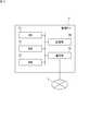
- FIG. 1is an overall configuration diagram of a program update system according to an embodiment of the present invention.
- the program update system of the present embodimentincludes a vehicle 1 that can communicate via the wide area communication network 2, a management server 5, and a DL (download) server 6.
- a communication device 9such as a smartphone or a tablet terminal carried by the user can also communicate with the vehicle 1 or the like through the wide area communication network 2.
- the management server 5manages the update information of the vehicle 1.
- the DL server 6stores the update program.
- the management server 5 and the DL server 6are operated, for example, by a car maker of the vehicle 1 and can communicate with a large number of vehicles 1 owned by a user who has been registered as a member in advance.
- an in-vehicle network (communication network) 4 including a plurality of ECUs 30 and a gateway 10 connected by an in-vehicle communication line, a wireless communication unit 15, and various in-vehicle devices (shown in FIG. And)are mounted.
- the in-vehicle deviceincludes a user interface device 7 such as a display, a speaker, and the like.
- the vehicle 1has a communication group by a plurality of ECUs 30 bus-connected to a common in-vehicle communication line, and the gateway 10 relays communication between the communication groups.
- the plurality of ECUs 30are capable of wirelessly communicating with the operation terminal 8 that receives a user operation instructing to start the engine etc., also called a so-called remote control key, and operate according to the instruction included in the wireless signal from the operation terminal 8 Including the ECU.
- the wireless communication unit 15is communicably connected to a wide area communication network 2 such as a cellular phone network, and is connected to the gateway 10 by an in-vehicle communication line.
- the gateway 10transmits the information received by the wireless communication unit 15 from an external device such as the management server 5 and the DL server 6 through the wide area communication network 2 to the ECU 30 via the in-vehicle communication line 16.
- the gateway 10transmits the information acquired from the ECU 30 to the wireless communication unit 15, and the wireless communication unit 15 transmits the information to an external device such as the management server 5 or the like. Further, the ECUs 30 transmit and receive information via an in-vehicle communication line.
- the wireless communication unit 15 mounted on the vehiclein addition to the dedicated communication terminal mounted on the vehicle, for example, a device such as a mobile phone owned by the user, a smartphone, a tablet terminal, a notebook PC (Personal Computer) can be considered.
- FIG. 1exemplifies a case where the gateway 10 communicates with an external device via the wireless communication unit 15, when the gateway 10 has a wireless communication function, the gateway 10 itself may be a management server 5 or the like.
- the configurationmay be such that wireless communication is performed with an external device.
- each of the management server 5 and the DL server 6may be composed of a plurality of devices.
- FIG. 2is a block diagram showing an internal configuration of the gateway 10.
- the gateway 10includes a CPU 11, a random access memory (RAM) 12, a storage unit 13, an in-vehicle communication unit 14, and the like.
- the gateway 10is connected to the wireless communication unit 15 via an in-vehicle communication line, but these may be configured by one device.
- the CPU 11causes the gateway 10 to function as a relay device for various information by reading out one or more programs stored in the storage unit 13 to the RAM 12 and executing the program.
- the CPU 11can execute a plurality of programs in parallel by switching and executing a plurality of programs in time division, for example.
- the CPU 11may represent a plurality of CPU groups. In this case, the functions realized by the CPU 11 are realized by the cooperation of a plurality of CPU groups.
- the RAM 12is configured by a memory element such as an SRAM (Static RAM) or a DRAM (Dynamic RAM), and temporarily stores programs executed by the CPU 11 and data required for the execution.
- the computer program realized by the CPU 11can be transferred while being recorded in a known recording medium such as a CD-ROM or a DVD-ROM, or can be transferred by information transmission from a computer device such as a server computer.
- transfer (transmission) of data to a lower device by the upper deviceis also referred to as “downloading”.
- the storage unit 13is configured by a non-volatile memory element such as a flash memory or an EEPROM.
- the storage unit 13stores a program executed by the CPU 11, data necessary for the execution, and the like, and stores an update program and the like of each ECU 30 to be downloaded, which is received from the DL server 6.
- a plurality of ECUs 30are connected to the in-vehicle communication unit 14 via an in-vehicle communication line disposed in the vehicle 1.
- the in-vehicle communication unit 14performs communication (also referred to as CAN communication) with the ECU 30 according to, for example, the standard of CAN (Controller Area Network).
- the communication standard adopted by the in-vehicle communication unit 14is not limited to CAN, and CANFD (CAN with Flexible Data Rate), LIN (Local Interconnect Network), Ethernet (registered trademark), or MOST (Media Oriented Systems Transport: MOST is a registered trademark) Or the like.
- the plurality of in-vehicle communication linesmay include different communication standards.
- the in-vehicle communication unit 14transmits the information given from the CPU 11 to the target ECU 30 and gives the information received from the ECU 30 to the CPU 11.
- the in-vehicle communication unit 14may communicate not only with the above communication standard but also with another communication standard used for the in-vehicle network 4.
- the wireless communication unit 15is a wireless communication device including an antenna and a communication circuit that performs transmission and reception of a wireless signal from the antenna.
- the wireless communication unit 15can communicate with an external device by being connected to a wide area communication network 2 such as a cellular phone network.
- the wireless communication unit 15transmits the information given from the CPU 11 to the device outside the vehicle such as the management server 5 via the wide area communication network 2 formed by the base station (not shown), and sends the information received from the device outside the vehicle to the CPU 11 give.
- a wired communication unit functioning as a relay device in the vehicle 1may be employed.
- the wired communication unithas a connector to which a communication cable conforming to the standard such as USB (Universal Serial Bus) or RS232C is connected, and performs wired communication with another communication device connected via the communication cable.
- a communication cable conforming to the standardsuch as USB (Universal Serial Bus) or RS232C
- FIG. 3is a block diagram showing an internal configuration of the ECU 30.
- the ECU 30includes a CPU 31, a RAM 32, a storage unit 33, a communication unit 34, and the like.
- the ECU 30is an on-vehicle control device that individually controls target devices mounted on the vehicle 1.
- the types of ECUs 30include, for example, a power supply control ECU, an engine control ECU, a steering control ECU, and a door lock control ECU.
- the CPU 31reads one or more programs stored in advance in the storage unit 33 into the RAM 32 and executes the programs to control the operation of the target device that the CPU 31 takes charge of.
- the CPU 31may also represent a plurality of CPU groups, and the control by the CPU 31 may be control by cooperation of a plurality of CPU groups.
- the RAM 32is configured by a memory element such as an SRAM or a DRAM, and temporarily stores programs executed by the CPU 31 and data necessary for the execution.
- the storage unit 33is configured by a non-volatile memory element such as a flash memory or an EEPROM, or a magnetic storage device such as a hard disk.
- the storage unit 33stores a program read and executed by the CPU 31.
- the information stored in the storage unit 33includes, for example, a computer program for causing the CPU 31 to execute information processing for controlling a target device to be controlled in the vehicle, and the program such as parameters and map information.
- the control programwhich is the data used at the time is included.
- a gateway 10is connected to the communication unit 34 via an in-vehicle communication line disposed in the vehicle 1.
- Communication unit 34communicates with gateway 10 in accordance with a standard such as CAN, Ethernet, or MOST, for example.
- the communication unit 34transmits the information given from the CPU 31 to the gateway 10, and gives the information received from the gateway 10 to the CPU 31.
- the communication unit 34may communicate not only with the above communication standard but also with another communication standard used for the in-vehicle network.
- the CPU 31 of the ECU 30includes an activation unit 35 that switches the control mode of the CPU 31 to either the “normal mode” or the “reprogramming mode”.
- the normal moderefers to a control mode in which the CPU 31 of the ECU 30 executes the inherent control (for example, engine control for the fuel engine, door lock control for the door lock motor, etc.) for the target device.
- the reprogramming modeis a control mode in which a control program used to control a target device is updated. That is, the reprogramming mode is a control mode in which the CPU 31 erases and rewrites data of the control program with respect to the ROM area of the storage unit 33. The CPU 31 can update the control program stored in the ROM area of the storage unit 33 to a new version only in this control mode.
- the activation unit 35When the CPU 31 writes the control program of the new version in the storage unit 33 in the reprogramming mode, the activation unit 35 once restarts (resets) the ECU 30 and executes verification processing on the storage area in which the control program of the new version is written. Do.
- the start-up unit 35operates the CPU 31 with the control program after the update after the completion of the verification process.
- the update programis downloaded from the DL server 6 to the ECU 30 via the gateway 10, and updating the control program using the update program is also referred to as online update.
- FIG. 4is a block diagram showing an internal configuration of the management server 5.
- the management server 5includes a CPU 51, a ROM 52, a RAM 53, a storage unit 54, a communication unit 55, and the like.
- the CPU 51reads one or a plurality of programs stored in advance in the ROM 52 into the RAM 53 and executes them to control the operation of each hardware, and causes the management server 5 to function as an external device capable of communicating with the gateway 10.
- the CPU 51may also represent a plurality of CPU groups, and a function realized by the CPU 51 may be realized by a plurality of CPU groups in cooperation.
- the RAM 53is configured of a memory element such as an SRAM or a DRAM, and temporarily stores programs executed by the CPU 51 and data required for the execution.
- the storage unit 54is configured of a non-volatile memory element such as a flash memory or an EEPROM, or a magnetic storage device such as a hard disk.
- the communication unit 55is a communication device that executes communication processing in accordance with a predetermined communication standard, and is connected to a wide area communication network 2 such as a mobile telephone network to execute the communication processing.
- the communication unit 55transmits the information provided from the CPU 51 to an external device via the wide area communication network 2, and supplies the information received via the wide area communication network 2 to the CPU 51.
- FIG. 5is a sequence diagram showing an example of the flow of on-line updating of the control program executed in the program updating system of the present embodiment.
- One or more update programsare stored in the DL server 6.
- the management server 5determines the timing of updating the control program of the ECU of the vehicle 1 registered in advance.
- the timing of the updatemay be set by, for example, a car maker of the vehicle 1 or the like.
- control programincludes not only the program itself but also data used when executing the program, such as parameters and map information. They are represented as "control program". Therefore, the update program includes not only the program for updating the program but also data for updating data used when the program is executed.
- the management server 5When it is time to update the control program, the management server 5 notifies the gateway 10 of the corresponding vehicle 1 of the update (step S1). In step 1, the management server 5 sends, to the gateway 10, update information such as the storage destination URL of the update program and the size of the update program together with the download request.
- the gateway 10having received the notification of update from the management server 5 relays the update program downloaded from the DL server 6 to an ECU (hereinafter, target ECU) 30 which updates the control program. That is, the gateway 10 requests the DL server 6 to download the update program based on the update information (step S2).
- the DL server 6 requested for download from the gateway 10transmits the update program to be downloaded to the gateway 10 and also requests update of the control program (step S3).
- the gateway 10transfers the update program to the target ECU 30, and requests update of the control program (step S4).
- the gateway 10may transfer the update program by receiving permission for update from the user.
- the target ECU 30 that has received the update programdevelops the update program according to the request from the gateway 10, and updates the control program (step S5).
- the gateway 10is an example of a control device that controls update processing in the target ECU 30.
- the gateway 10executes an update control process (step S6).
- the update control processis a process of controlling the continuation of the update process started in the target ECU 30. The update control process will be described later.
- the target ECU 30When the update of the control program is completed, the target ECU 30 notifies the gateway 10 of the update completion (step S7).
- the gateway 10 having received this notificationnotifies the DL server 6 of the update completion (step S8).
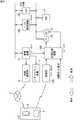
- FIG. 6is a schematic diagram showing an example of a configuration including the power supply configuration of the vehicle 1 according to the first embodiment.
- FIG. 6shows an example of the configuration of a conventional vehicle (engine vehicle) that is not a hybrid vehicle, also called a conventional vehicle.
- thick linesindicate power lines.
- the vehicle 1includes power supplies of a battery (BAT) 21 and an alternator (ALT) 23.
- BATbattery
- ALTalternator
- the battery 21supplies power to a battery monitoring device 30A, which is an ECU for battery control, another ECU 30C, a starter (ST) 24 for starting an engine, and the like.
- a battery monitoring device 30Awhich is an ECU for battery control, another ECU 30C, a starter (ST) 24 for starting an engine, and the like.
- an ECUsuch as the ECU 30C is a target ECU.
- the ALT 23can also supply power to these devices. Furthermore, the battery 21 is charged by the power generated by the ALT 23. That is, the ALT 23 is a mechanism for supplying power to the battery 21.
- the starter 24is an ECU for engine control and is connected to a start control device 30B that controls the start of the engine, and the drive is controlled by the start control device 30B.
- the start control device 30Bcontrols the starter 24 to operate at engine start, and controls the starter 24 to stop operation when the engine starts.
- the ALT 23 connected to the enginegenerates power when the engine operates. Therefore, it can be said that start control device 30B also controls the power generation operation of ALT 23.
- the start control device 30Bis connected to the reception unit 30D, which is a body-system ECU, which receives a wireless signal from the operation terminal 8, and drives the engine according to the user operation received from the operation terminal 8 via the reception unit 30D. Control. In addition, start control device 30B controls the driving of the engine in accordance with a user operation instructing start of the engine to a switch, a key, etc. not shown. The start control device 30B also controls the driving of the engine in accordance with the user operation received from the communication device 9 via the wireless communication unit 15. Furthermore, the start control device 30B is connected to the gateway 10 that is a management device of the update process, and controls the driving of the engine according to the control of the gateway 10.
- the gateway 10is further connected to the battery monitoring device 30A, and acquires the battery state such as the remaining amount of the battery 21 from the battery monitoring device 30A.
- the gateway 10executes an update control process when the control program is updated by the ECU 30C which is a target ECU, and controls the start control device 30B according to the process.
- the gateway 10is connected to the user interface device 7 or connected to the user interface device 7 via an ECU (not shown) for controlling the media device, and controls the user interface device 7 to output necessary information. Do.
- the gateway 10passes information for output to the wireless communication unit 15 so as to output necessary information to the communication device 9.
- Update control processThe update control process of step S6 of FIG. 5 includes STEPs 1 to 3 below.
- STEP 1First acquisition process for acquiring remaining charge of battery 21
- STEP 2Second acquisition process for acquiring predicted amount of power consumption of vehicle 1 up to completion of update process in target ECU 30
- STEP 3With remaining capacity of battery 21 Determination processing for determining whether or not the predicted remaining charge of the battery 21 at the time of completion of the update processing in the target ECU 30 is insufficient based on the predicted amount of power consumption
- the gateway 10controls the update process in the target ECU 30 according to the result of the determination process. That is, when it is determined that the predicted remaining charge amount is insufficient by the determination processing, the gateway 10 performs control for increasing the remaining charge amount of the battery 21.
- CPU 11 of gateway 10includes an update control unit 111 as a function for executing the update control process.
- the update control unit 111includes a first acquisition unit 112 that executes the first acquisition process, a second acquisition unit 113 that performs the second acquisition process, and a determination unit 114 that performs the determination process.
- These functionsare functions realized by the CPU 11 by reading and executing one or a plurality of programs stored in the storage unit 13 by the CPU 11. However, at least part of the function may be realized by hardware such as an electronic circuit.
- the function of the CPU 11 represented by the first acquisition unit 112acquires the monitoring result of the state of the battery 21 from the ECU 30A by monitoring a frame received from the ECU 30A that performs power control. .
- the first acquisition unit 112acquires the remaining charge amount (remaining battery amount) SOC of the battery 21 based on the monitoring result.
- the function of the CPU 11 represented by the second acquisition unit 113acquires the power consumption state of the vehicle 1 at the time of acquisition of the battery remaining amount SOC in the first acquisition unit 112
- a predicted amount of power consumption (hereinafter, also simply referred to as a predicted power consumption amount) DW of the vehicle 1 from the time point until the update processing in the target ECU 30 is completedis acquired.
- the power consumption prediction amount DWis a power amount DW1 required in the target ECU and a power amount DW2 predicted to be consumed in other ECUs other than the target ECU during the time from the acquisition time until the update processing is completed.
- the electric energy DW2is predicted to be consumed between the acquisition time point and the completion of the update process in the target ECU in all ECUs other than the target ECU among the plurality of ECUs 30 mounted on the vehicle 1 It can be said that it is the sum total of electric energy.
- the second acquisition unit 113monitors the frame received from the ECU 30A to acquire the consumption current at the acquisition time of the target ECU in the update process and the average value of the consumption current during a predetermined period before and after the acquisition time.
- the electric power amount DW1may be calculated by multiplying the current consumption by the remaining time until the update processing is completed.
- the second acquisition unit 113monitors the frame received from the ECU 30A to acquire the consumed current in the devices other than the target ECU and the average value thereof, and multiplies the consumed current by the remaining time until the update processing is completed.
- the power amount DW2may be calculated.
- the second acquisition unit 113may acquire the electric energy DW1 from the management server 5, or may calculate it from the size of the update program acquired from the management server 5 and the processing capacity of the target ECU. May be
- the determination unit 114stores in advance the threshold value Th of the power amount, and compares it with the predicted remaining amount SOC '.
- the threshold This, for example, a predefined margin (safety margin) or the like, and at least indicates the amount of power required for the vehicle 1 to operate.
- the determination unit 114compares the predicted remaining amount SOC ′ with the threshold value Th (first determination).
- the determination unit 114determines that the predicted remaining amount SOC 'is insufficient when the predicted remaining amount SOC' is smaller (smaller) than the threshold Th, and the predicted remaining amount SOC is larger (larger) than the threshold Th. Determine that 'is not short.
- the function of the CPU 11(hereinafter, the update control unit 111) represented by the update control unit 111 controls the update process in the target ECU 30 according to the determination result of the determination unit 114. If the determination unit 114 determines that the predicted remaining amount SOC 'is not insufficient in the first determination process, the update control unit 111 executes control to continue the update process in the target ECU. That is, in this case, the update control unit 111 does not execute control for stopping the update of the target ECU or control for notifying the user interface device 7 described later. Further, in this case, the update control unit 111 does not execute the charging process of the battery 21 described later.
- the update control unit 111executes a process of charging the battery 21. As a result, the remaining battery charge SOC increases.
- the update control unit 111executes a process (request process) of requesting the user to start the charging operation.
- the request processis a process of causing the user interface to output information (starting operation promotion information) for prompting a charge start instruction to the user.
- the user operationincludes the first operation to the third operation below.
- First operationoperation using the user interface provided in the vehicle 1 such as switches and keys not shown
- Second operationoperation using the operation terminal 8
- Third operationusing the communication device 9 such as a smartphone Operation
- the first operationis an operation that can be performed when the user is in the vehicle
- the second operation and the third operationare operations that can be performed by the user either inside or outside the vehicle.
- an operation signalis input from the user interface to the start control device 30B.
- the operation signalis received by the receiving unit 30D and input to the start control device 30B.
- These user operationsare detected by the gateway 10 that monitors the transmission signal of the start control device 30B.
- the operation signalis received by the wireless communication unit 15 via the wide area communication network 2 and input to the gateway 10.
- the request processincludes a request process (first request process) when the user is in the vehicle and a request process (second request process) when the user is not in the vehicle.
- Whether or not the user is in the vehiclecan be determined, for example, by monitoring a frame from the ECU 30D communicating with the operation terminal 8 whether the operation terminal 8 carried by the user is in a wirelessly communicable range. Further, as another example, it may be determined whether the user is seated in the vehicle using a seating sensor (not shown) provided on a seat in the vehicle, or an image captured by an in-vehicle camera (not shown) is analyzed It may be determined whether the user is in the car.
- the update control unit 111executes a first request process.
- the first request processis a process of causing the user interface device 7 to output start operation promotion information.
- the start operation promotion informationis a screen for requesting engine start. If the user interface device 7 is a speaker, the start operation promotion information is a voice message requesting engine start.
- the update control unit 111generates a frame including output data, and causes the in-vehicle communication unit 14 to transmit the frame to the user interface device 7.
- the update control unit 111executes a second request process.
- the second request processis a process of transmitting start operation promotion information to the communication device 9 of the user registered in advance.
- the update control unit 111generates a frame including transmission data, inputs the frame to the wireless communication unit 15, and causes the wireless communication unit 15 to transmit the start operation promotion information.
- the update control unit 111When detecting the charge start operation, the update control unit 111 instructs the start control device 30B to start the engine. Specifically, the update control unit 111 generates a frame including data instructing engine start, and causes the in-vehicle communication unit 14 to transmit the frame to the start control device 30B.
- determination unit 114compares battery remaining amount SOC with threshold value Th prior to the first determination (second determination). The determination unit 114 determines that the battery remaining capacity SOC is insufficient when the battery remaining capacity SOC is smaller (smaller) than the threshold Th, and the battery remaining capacity SOC is insufficient when it is larger (larger) than the threshold Th. It determines that it does not do.
- the update control unit 111instructs the target ECU to cancel the update. Specifically, the update control unit 111 generates a frame including data instructing cancellation of the update, and causes the in-vehicle communication unit 14 to transmit the frame to the target ECU. Thus, the update process in the target ECU is canceled.
- determination unit 114executes the second determination process when it is determined in the first determination process that the battery remaining amount SOC is not short. That is, the update control unit 111 executes the charge processing of the battery 21 when the determination unit 114 determines that the battery remaining amount SOC is not insufficient and the predicted remaining amount SOC 'is insufficient.
- FIG. 7is a flowchart showing a specific example of the update control process of step S6 of FIG.
- the processing shown in the flowchart of FIG. 7realizes each function shown in FIG. 2 by the CPU 11 of the gateway 10 reading out one or more programs stored in the storage unit 13 onto the RAM 12 and executing the program. It is executed by doing.
- the process of FIG. 7is started when the gateway 10 requests the target ECU to update in step S4 of FIG.
- CPU 11executes the second determination process described above. That is, the CPU 11 monitors the frame from the ECU 30A and acquires the battery remaining amount SOC (step S101). Then, the CPU 11 compares the battery remaining amount SOC with the threshold value Th stored in advance.
- step S119If the remaining battery amount SOC is less than the threshold Th (NO in step S103), the cancellation of the update process in the target ECU is instructed (step S119).
- the CPU 11executes request processing. At this time, the process branches to the first request process or the second request process depending on whether the user is in the vehicle. Therefore, the CPU 11 determines whether the user is in the vehicle by monitoring a frame from the ECU 30D communicating with the operation terminal 8 or the like.
- the CPU 11executes a first request process. That is, the CPU 11 displays a screen for requesting the user to start the engine on the user interface device 7 which is, for example, a display (step S111).
- step S109If it is determined that the user is not in the car (NO in step S109), the CPU 11 executes a second request process. That is, the CPU 11 transmits the start operation promotion information to the communication device 9 of the user of the vehicle 1 registered in advance (step S113).
- step S115When the charge start operation is detected after the first request process of step S111 or the second request process of step S113 (YES in step S115), the CPU 11 instructs the start control device 30B to start the engine ( Step S117). Then, the CPU 11 ends the series of operations.
- the CPU 11After the first or second request process, when the charge start operation is not detected within the predetermined period (NO in step S115), the CPU 11 does not instruct the start control device 30B to start the engine. Further, even when the predicted remaining amount SOC 'is larger than the threshold Th in the second determination process (YES in step S107), the CPU 11 does not instruct the start control device 30B to start the engine.
- the battery remaining amount SOCruns short at least when the update is completed. Further, even if the predicted remaining amount SOC 'is equal to or higher than the threshold value Th (YES in step S107), the battery remaining amount SOC may be insufficient depending on the power consumption status of other ECUs other than the target ECU during updating. . Therefore, preferably, the CPU 11 repeats the process from step S101 after a predetermined time has elapsed from the request process or after a predetermined time has elapsed from the first determination process.
- the useris prompted to start charging when it is predicted that the remaining battery capacity will be insufficient at the update completion time while the control program is being updated.
- the engineis driven in the vehicle 1 according to the present embodiment.
- the ALT 23generates power, and the battery 21 is charged by the generated power.
- the program update systemin addition to the power consumption required by the target ECU when predicting the battery remaining amount at the time of completion of the update, it is predicted from the current power consumption of other devices The estimated value of the power consumption until the completion of the update is also taken into account. Therefore, the remaining battery capacity can be predicted with high accuracy.
- the control of the engine operation in the gateway 10may include a normal operation mode operated in a traveling state of the vehicle 1 and an update operation mode operated for charging the battery 21 during the update process.
- the gateway 10may simultaneously activate other functions such as, for example, an air conditioner and audio according to the setting when the engine is started.
- the update operation modethe gateway 10 starts only the engine regardless of the setting in the normal operation mode. Thereby, the battery 21 can be charged efficiently. This control is the same as in the second and third embodiments described later.
- the update control process of the program update system according to the second embodimentincludes control for stopping the operation of the engine after instructing the engine start in step S117 of FIG. 7. Therefore, the determination unit 114 according to the second embodiment determines that the predicted remaining amount SOC 'is insufficient in the first determination process, and instructs the start of the engine in step S117 of FIG. 7. After that, a third determination process is performed to determine whether the engine needs to be stopped. The same control may be performed in the program update system according to the third embodiment described later.
- the first acquisition unit 112acquires the remaining battery charge SOC after the engine is started.
- the second acquisition unit 113acquires the predicted power consumption DW after the engine is started.
- Determination unit 114calculates predicted remaining amount SOC 'from battery remaining amount SOC and power consumption predicted amount DW obtained after the engine is started, and compares predicted remaining amount SOC' with threshold value Th.
- the calculation method of the power consumption prediction amount DWis the same as the calculation method in the determination unit 114 according to the first embodiment.
- the determining unit 114determines that the predicted remaining amount SOC ′ is not short. This means that the battery residual amount SOC has increased until the predicted residual amount SOC 'does not run short after the engine is started.
- the update control unit 111generates a frame including data for instructing to stop the engine according to the determination result of the third determination process, and transmits the frame to the in-vehicle communication unit 14 to the ECU 30B that controls the engine. Let This shuts off the engine.
- FIG. 8is a flowchart showing a specific example of the update control process of step S6 of FIG. 5, and is a flowchart showing an operation performed after the operation shown in the flowchart of FIG.
- the CPU 11continues the operation of the engine without instructing the engine to stop.
- the CPU 11repeats the above process after a predetermined time has elapsed from the third determination process of step S209.
- step S209If the predicted remaining amount SOC 'is equal to or greater than the threshold Th (YES in step S209), the CPU 11 instructs the start control device 30B to stop the engine (step S211). Then, the CPU 11 ends the series of operations.
- ⁇ Modification>Referring to FIG. 8, preferably, after instructing the start of the engine in step S117, if it is determined that the user is not in the vehicle (NO in step S201), CPU 11 sends an instruction to an ECU other than the target ECU. In response to this, an instruction to stop other functions is issued (step S203).
- Other functionscorrespond to, for example, an air conditioner and audio.
- the air conditioner, the audio, and the likemay be able to be turned on / off by the second operation or the third operation. For example, it may be assumed that the interior of the vehicle is kept at an appropriate temperature before driving. However, when these functions are operating, the remaining battery charge SOC is further reduced. Therefore, the amount of power consumption of the vehicle 1 can be suppressed by stopping these functions.
- controlis not limited to the program update system according to the second embodiment, and may be performed after step S117 even in the program update system according to the first embodiment.
- the program update system according to the third embodiment described latermay also be executed.
- the vehicle 1is a so-called engine vehicle, but the same update control process is performed even if the vehicle 1 is an electric vehicle without an engine and an alternator. It may be done.
- FIG. 9is a schematic diagram showing an example of a configuration including a power supply configuration of the vehicle 1 according to the third embodiment.
- FIG. 9shows an example of the configuration of an electric vehicle (electric vehicle).
- thick linesindicate power lines.
- the vehicle 1 according to the third embodimentis different from the battery 21, ALT 23 and starter 24 (FIG. 6) of the vehicle 1 according to the first embodiment with a high voltage battery 21A and , Power supply for auxiliary system battery 21B for system startup and for supplying power to each device.
- High-voltage battery 21Ais a running battery that supplies power to a drive device of a motor (not shown) to start the drive system, and reduces the voltage via DC / DC converter 22 to supply power to auxiliary battery 21B. , It is also a battery for charging.
- the auxiliary battery 21Bsupplies power to the battery monitoring device 30A, the other ECU 30C, and the like.
- an ECUsuch as the ECU 30C is a target ECU.
- the auxiliary battery 21Bis charged by the power supplied from the high voltage battery 21A via the DC / DC converter 22. That is, high voltage battery 21A and DC / DC converter 22 are mechanisms for supplying power to auxiliary battery 21B.
- the start control device 30Bcontrols the start of a drive system (not shown) and controls the ON / OFF of the DC / DC converter 22 and the output voltage.
- the start control device 30Bcontrols the start of a drive system (not shown) and controls the ON / OFF of the DC / DC converter 22 and the output voltage.
- the start control device 30Bcontrols the ON / OFF of the DC / DC converter 22 in accordance with the user's operation on switches and keys (not shown). Further, the start control device 30B controls ON / OFF of the DC / DC converter 22 in accordance with the user operation received from the communication device 9 via the wireless communication unit 15. Furthermore, the start control device 30B is connected to the gateway 10, which is a management device of the update process, and controls ON / OFF of the DC / DC converter 22 according to the control of the gateway 10. The gateway 10 is further connected to the battery monitoring device 30A, and acquires the battery state such as the remaining amount of the high voltage battery 21A from the battery monitoring device 30A.
- the update control process in the program update system according to the third embodimentis substantially the same as the update control process in the program update system according to the first embodiment shown in FIG.
- the CPU 11 of the gateway 10executes update control processing based on the battery remaining amount SOC 'of the auxiliary battery 21B.
- the charge start operationis a user operation that instructs the DC / DC converter 22 to be turned on.
- the program update systemwhen battery remaining amount SOC ′ is less than threshold value Th (NO in step S107), CPU 11 determines whether the user is in step S111 or step S113.
- the start operation promotion information for requesting the charge start operationwhich is the operation to turn on the DC / DC converter 22 is output.
- the CPU 11instructs the start control device 30B to turn on the DC / DC converter 22 instead of the start of the engine (step S117).
- the update control process described aboveis executed to stop the update due to the shortage of the battery SOC during the update, causing the update to fail or the update program to be damaged. It is possible to avoid doing
- the disclosed featuresare realized by one or more modules.
- the featurecan be realized by a circuit element or other hardware module, a software module that defines a process for realizing the feature, or a combination of a hardware module and a software module.
- the programmay be provided as a program that is a combination of one or more software modules for causing a computer to execute the above-described operations.
- a programis provided as a program product by recording it on a computer readable recording medium such as a flexible disk attached to a computer, a CD-ROM (Compact Disk-Read Only Memory), a ROM, a RAM and a memory card. It can also be done.
- the programcan be provided by being recorded in a recording medium such as a hard disk built in the computer.
- the programcan be provided by downloading via a network.
- the program according to the present disclosureis to call a necessary module among program modules provided as a part of an operating system (OS) of a computer in a predetermined arrangement at a predetermined timing to execute processing. It is also good. In that case, the program itself does not include the above module, and the processing is executed in cooperation with the OS. Programs not including such modules may also be included in the programs according to the present disclosure.
- OSoperating system
- the program according to the present disclosuremay be provided by being incorporated into a part of another program. Also in this case, the program itself does not include a module included in the other program, and the process is executed in cooperation with the other program. Programs incorporated into such other programs may also be included in the programs according to the present disclosure.
- the provided program productis installed and executed in a program storage unit such as a hard disk.
- the program productincludes the program itself and a recording medium in which the program is recorded.
Landscapes
- Engineering & Computer Science (AREA)
- Mechanical Engineering (AREA)
- Transportation (AREA)
- Power Engineering (AREA)
- Life Sciences & Earth Sciences (AREA)
- Sustainable Energy (AREA)
- Sustainable Development (AREA)
- Software Systems (AREA)
- Theoretical Computer Science (AREA)
- General Engineering & Computer Science (AREA)
- General Physics & Mathematics (AREA)
- Physics & Mathematics (AREA)
- Computer Security & Cryptography (AREA)
- Stored Programmes (AREA)
Abstract
Description
Translated fromJapanese この発明は制御装置、制御方法、およびコンピュータプログラムに関する。
本出願は、2017年8月10日出願の日本出願第2017-155930号に基づく優先権を主張し、前記日本出願に記載された全ての記載内容を援用するものである。The present invention relates to a control device, a control method, and a computer program.
This application claims the priority based on Japanese Patent Application No. 2017-155930 filed on Aug. 10, 2017, and incorporates all the contents described in the Japanese application.
近年、自動車の技術分野においては、車両の高機能化が進行しており、多種多様な車載機器が車両に搭載されている。従って、車両には、各車載機器を制御するための制御装置である、所謂ECU(Electronic Control Unit)が多数搭載されている。
ECUの種類には、例えば、アクセル、ブレーキ、ハンドルの操作に対してエンジンやブレーキ、EPS(Electric Power Steering)等の制御を行う走行系に関わるもの、乗員によるスイッチ操作に応じて車内照明やヘッドライトの点灯/消灯と警報器の吹鳴等の制御を行うボディ系ECU、運転席近傍に配設されるメータ類の動作を制御するメータ系ECUなどがある。2. Description of the Related Art In recent years, in the technical field of automobiles, vehicles are becoming more sophisticated, and a wide variety of on-vehicle devices are mounted on the vehicles. Therefore, a large number of so-called ECUs (Electronic Control Units), which are control devices for controlling each on-vehicle device, are mounted on the vehicle.
The types of ECUs include, for example, those related to a travel system that controls the engine, brakes, EPS (Electric Power Steering), etc. in response to accelerator, brake, and steering wheel operations, and in-vehicle lighting and head according to switch operation by occupant There are a body system ECU that controls lighting / extinguishing of a light and sounding of an alarm device, and a meter system ECU that controls the operation of meters disposed near the driver's seat.
一般的にECUは、マイクロコンピュータ等の演算処理装置によって構成されており、ROM(Read Only Memory)に記憶した制御プログラムを読み出して実行することにより、車載機器の制御が実現される。
ECUの制御プログラムは、車両の仕向け地やグレードなど応じて異なることがあり、制御プログラムのバージョンアップに対応して、旧バージョンの制御プログラムを新バージョンの制御プログラムに書き換える必要がある。また、たとえば地図情報や制御用のパラメータなど、制御プログラムの実行に必要なデータも書き換える必要がある。Generally, the ECU is configured by an arithmetic processing unit such as a microcomputer, and the control of the on-vehicle device is realized by reading and executing the control program stored in a ROM (Read Only Memory).
The control program of the ECU may differ depending on the destination or grade of the vehicle, and it is necessary to rewrite the control program of the old version to the control program of the new version in response to the upgrade of the control program. Further, it is also necessary to rewrite data necessary for executing the control program, such as map information and control parameters.
たとえば、特許文献1には、ネットワークを介して更新用のプログラムをダウンロードし、プログラムの更新を行う技術(オンライン更新機能)が開示されている。また、特許文献2には、オンライン更新の際に、バッテリ残量が更新処理の消費電力から規定値以上多いことを確認してオンライン更新を開始する技術が開示されている。For example, Patent Document 1 discloses a technology (on-line update function) of downloading a program for update via a network and updating the program. Further,
ある実施の形態に従うと、制御装置は、1または複数の車載制御装置と車内通信線を介して通信する通信部と、車載制御装置に電力を供給するバッテリの残電量を取得する第1の取得部と、車載制御装置での制御プログラムの更新完了時点までの、各車載制御装置での消費電力予測量を取得する第2の取得部と、バッテリの残電量と消費電力予測量とに基づいて、更新完了時点におけるバッテリの予測残電量が閾値以上であるか否かを判定する第1の判定処理を実行する判定部と、通信部を介して、1または複数の車載制御装置に対して、当該車載制御装置の制御する装置の動作を指示する制御部と、を備え、制御部は、予測残電量が閾値未満であることが制御プログラムの更新中の第1の時点において判定された場合に、ユーザインタフェース装置にバッテリの充電開始操作を促す情報出力を行わせる。According to an embodiment, the control device acquires the remaining charge of the battery that supplies power to the in-vehicle control device and the communication unit that communicates with the one or more in-vehicle control devices via the in-vehicle communication line. And a second acquisition unit for acquiring the predicted power consumption in each in-vehicle control device until the completion of updating the control program in the in-vehicle control device, and based on the remaining charge of the battery and the predicted power consumption A determination unit that executes a first determination process that determines whether or not the predicted remaining charge of the battery at the update completion time is equal to or greater than a threshold, and for one or more in-vehicle control devices via the communication unit; A control unit that instructs an operation of a device controlled by the on-vehicle control device, and the control unit determines that the predicted remaining charge amount is less than the threshold at a first point in time during the updating of the control program. , User interface To perform information output prompting charging start operation of the battery to the over scan device.
他の実施の形態に従うと、制御方法は車載制御装置と車内通信線を介して通信する制御装置による、前記車載制御装置の制御方法であって、車載制御装置に電力を供給可能なバッテリの残電量を取得するステップと、車載制御装置での制御プログラムの更新完了時点までの、各車載制御装置での消費電力予測量を取得するステップと、制御プログラムの更新中のバッテリの残電量と消費電力予測量とに基づいて、更新完了時点におけるバッテリの予測残電量が閾値以上であるか否かを判定するステップと、車載制御装置に対して、当該車載制御装置の制御する装置の動作を指示するステップと、を備え、指示するステップは、予測残電量が閾値未満であることが制御プログラムの更新中に判定された場合に、ユーザインタフェース装置にバッテリの充電開始操作を促す情報出力を行わせることを含む。According to another embodiment, the control method is a method of controlling the on-board control device by a control device that communicates with the on-board control device via an in-vehicle communication line, and the remaining control method enables to supply power to the on-board control device. The step of acquiring the amount of electricity, the step of acquiring the predicted amount of power consumption in each in-vehicle control device up to the completion of updating the control program in the in-vehicle control device, and the remaining power and power consumption of the battery during the update of the control program Determining whether the predicted remaining charge of the battery at the update completion time is equal to or greater than a threshold based on the predicted amount, and instructing the on-vehicle control device to operate the device controlled by the on-vehicle control device And instructing the user interface device to determine whether the estimated remaining charge is less than the threshold value during the control program update. Including that causes the information output to prompt the charging start operation of Teri.
他の実施の形態に従うと、コンピュータプログラムは車載制御装置と車内通信線を介して通信する制御装置としてコンピュータを機能させるためのコンピュータプログラムであって、コンピュータを、車載制御装置に電力を供給するバッテリの残電量を取得する第1の取得部と、車載制御装置での制御プログラムの更新完了時点までの、各車載制御装置での消費電力予測量を取得する第2の取得部と、バッテリの残電量と消費電力予測量とに基づいて、更新完了時点におけるバッテリの予測残電量が閾値以上であるか否かを判定する判定処理を実行する判定部と、車載制御装置に対して、当該車載制御装置の制御する装置の動作を指示する制御部、として機能させ、制御部は、予測残電量が閾値未満であることが制御プログラムの更新中に判定された場合に、ユーザインタフェース装置にバッテリの充電開始操作を促す情報出力を行わせる。According to another embodiment, the computer program is a computer program for causing a computer to function as a control device that communicates with the in-vehicle control device via an in-vehicle communication line, and a battery for supplying power to the in-vehicle control device. A first acquisition unit for acquiring the remaining charge of the battery, a second acquisition unit for acquiring a predicted power consumption in each on-vehicle control device until the update completion time of the control program on the on-vehicle control device, and a remaining battery A determination unit that executes a determination process of determining whether the estimated remaining charge of the battery at the update completion time is equal to or greater than a threshold based on the amount of power and the estimated amount of power consumption; The control unit functions as a control unit that instructs the operation of the device controlled by the device, and the control unit determines that the predicted remaining charge is less than the threshold during updating of the control program. If it is constant, causing the information output to the user interface device prompts the charging start operation of the battery.
<本開示が解決しようとする課題>
文献1に開示されているオンライン更新は、一般的にエンジン停止時に開始される。そのため、バッテリ残量が少ないと、更新中に電力不足となって更新に失敗したり、バッテリ残量が走行に不足し、走行できなくなったりする場合がある。それに対して文献2の技術を用いると、オンライン更新の開始時のバッテリ残量が確保されていた場合にはオンライン更新が開始される。そのため、当該車両において更新の開始時の電力消費状態が継続した場合には、更新処理中に電力不足となったり、更新完了時にバッテリ残量が走行に不足したりすることが回避される。<Issues the present disclosure is trying to solve>
The on-line update disclosed in Document 1 is generally started at engine stop. Therefore, when the battery remaining amount is low, the power may be insufficient during the update, the update may fail, or the battery remaining amount may not be sufficient for running, which may make it impossible to run. On the other hand, when the technology of
しかしながら、更新の開始時にバッテリ残量の不足が予測されなかった場合であっても、更新中のエアコンの作動やオーディオの作動などの他の機器の使用状況によっては、バッテリ残量が想定以上に低下する場合もある。つまり、文献2の技術を利用した場合であっても、更新開始後の電力消費状態によっては、更新中に電力不足となる場合がある。この場合、更新が中断して更新に失敗したり、更新用プログラムが破損したりする場合がある。また、更新処理が完了した場合であっても、完了後、走行に必要な電力が不足し、その後に車両が走行できなくなる場合がある。However, even if a battery shortage is not predicted at the start of the update, depending on the use of other devices such as the operation of the air conditioner and the operation of the audio during the update, the battery remaining capacity is higher than expected. It may decrease. That is, even when the technique of
本開示のある局面における目的は、制御プログラムの更新完了後にバッテリ残量が不足した状態となっていることを回避できる制御装置、制御方法、およびコンピュータプログラムを提供することである。An object in one aspect of the present disclosure is to provide a control device, a control method, and a computer program that can avoid the state where the battery remaining amount is insufficient after the update of the control program is completed.
<本開示の効果>
この開示によると、制御プログラムの更新完了後にバッテリ残量が不足した状態となっていることを回避することができる。<Effect of the present disclosure>
According to this disclosure, it is possible to avoid the state where the battery remaining amount is insufficient after the update of the control program is completed.
[実施の形態の説明]
本実施の形態には、少なくとも以下のものが含まれる。すなわち、
(1)本実施の形態に含まれる制御装置は、1または複数の車載制御装置と車内通信線を介して通信する通信部と、車載制御装置に電力を供給するバッテリの残電量を取得する第1の取得部と、車載制御装置での制御プログラムの更新完了時点までの、各車載制御装置での消費電力予測量を取得する第2の取得部と、バッテリの残電量と消費電力予測量とに基づいて、更新完了時点におけるバッテリの予測残電量が閾値以上であるか否かを判定する第1の判定処理を実行する判定部と、通信部を介して、1または複数の車載制御装置に対して、当該車載制御装置の制御する装置の動作を指示する制御部と、を備え、制御部は、予測残電量が前記閾値未満であることが制御プログラムの更新中の第1の時点において判定された場合に、ユーザインタフェース装置にバッテリの充電開始操作を促す情報出力を行わせる。
各車載制御装置での消費電力予測量を用いてバッテリの残電量を予測することによって、更新完了時点のバッテリの残電量が高精度で予測される。そして、更新完了時点のバッテリの残電量が閾値未満である場合に、ユーザに対して充電開始操作が促される。当該充電開始操作が行われることで、バッテリが充電される。これにより、更新完了後にバッテリの残電量が不足した状態となることを回避できる。[Description of the embodiment]
The present embodiment includes at least the following. That is,
(1) The control device included in the present embodiment acquires a remaining charge of a battery that supplies power to the in-vehicle control device and a communication unit that communicates with one or more in-vehicle control devices via an in-vehicle communication line 1 and an acquisition unit for acquiring the power consumption prediction amount in each on-vehicle control device until the update completion time of the control program in the on-vehicle control device, the remaining charge of the battery and the power consumption prediction amount Based on the determination unit that executes the first determination process that determines whether or not the estimated remaining charge of the battery at the update completion time is equal to or greater than the threshold, and one or more in-vehicle control devices via the communication unit A control unit for instructing the operation of the device controlled by the on-vehicle control device, and the control unit determines that the predicted remaining charge amount is less than the threshold at a first time point during the updating of the control program If the user To perform information output prompting charging start operation of the battery to the interface device.
By predicting the remaining charge of the battery using the power consumption prediction amount in each on-vehicle control device, the remaining charge of the battery at the time of completion of the update can be predicted with high accuracy. Then, when the remaining charge of the battery at the update completion time is less than the threshold value, the user is prompted for the charge start operation. The battery is charged by performing the charge start operation. As a result, it is possible to prevent the state in which the remaining charge of the battery is insufficient after the update is completed.
(2)好ましくは、ユーザインタフェース装置は車外のユーザインタフェース装置を含み、制御部は、ユーザが車内にいない場合には、車外のユーザインタフェース装置に情報出力を行わせる。
これにより、ユーザが車外である場合には、当該ユーザが確認可能な車外のユーザインタフェース装置によって、当該ユーザに対して充電開始操作が促される。このため、ユーザが車外であっても、遠隔での当該ユーザ操作が促され、より確実にバッテリが充電されるようになる。これにより、更新完了後にバッテリの残電量が不足した状態となることを回避できる。(2) Preferably, the user interface device includes a user interface device outside the vehicle, and the control unit causes the user interface device outside the vehicle to output information when the user is not in the vehicle.
Thus, when the user is outside the vehicle, the user interface device outside the vehicle that can be confirmed by the user prompts the user to start charging. Therefore, even if the user is outside the vehicle, the user's operation remotely is prompted, and the battery can be charged more reliably. As a result, it is possible to prevent the state in which the remaining charge of the battery is insufficient after the update is completed.
(3)好ましくは、ユーザインタフェース装置は車載のユーザインタフェース装置を含み、制御部は、ユーザが車内にいる場合には、車載のユーザインタフェース装置に情報出力を行わせる。
これにより、ユーザが車内にいる場合には、当該ユーザが確認可能な車載のユーザインタフェース装置によって、当該ユーザに対して充電開始操作が促される。このため、より確実にバッテリが充電されるようになる。これにより、更新完了後にバッテリの残電量が不足した状態となることを回避できる。(3) Preferably, the user interface device includes an in-vehicle user interface device, and the control unit causes the in-vehicle user interface device to output information when the user is in the vehicle.
Thereby, when the user is in the car, the user can be prompted to start charging by the on-vehicle user interface device that can be confirmed by the user. As a result, the battery is more reliably charged. As a result, it is possible to prevent the state in which the remaining charge of the battery is insufficient after the update is completed.
(4)好ましくは、充電開始操作に従ってバッテリの充電が開始された場合に、判定部は、第1の時点より後の第2の時点で第1の判定処理を実行し、制御部は、予測残電量が閾値以上であることが第2の時点において判定された場合に、バッテリに電力を供給する機構にバッテリへの電力供給を停止させる。
車両がいわゆるエンジン車である場合、バッテリに電力を供給する機構はオルタネータを含む。この場合、制御部は、オルタネータからバッテリへの電力供給を停止させるために、オルタネータが接続されたエンジンの稼動を停止させる。また、車両がいわゆるハイブリッド車や電気自動車である場合、バッテリに電力を供給する機構は、走行用の高圧バッテリから車載制御装置に電力供給する補機バッテリに電力供給する際に降圧するためのDC/DCコンバータを含む。この場合、制御部は、高圧バッテリから補機バッテリへの電力供給を停止させるために、DC/DCコンバータをOFFとする。これにより、更新完了時点のバッテリの予測残電量が閾値以上となるまでバッテリが充電されたと判定されると充電が停止される。そのため、更新完了後にバッテリの残電量が不足した状態となることを回避できるとともに、過剰な充電を防止できる。(4) Preferably, when charging of the battery is started according to the charge start operation, the determination unit executes the first determination process at a second time point after the first time point, and the control unit predicts If it is determined at the second point in time that the remaining charge amount is equal to or greater than the threshold value, the mechanism for supplying power to the battery is caused to stop supplying power to the battery.
When the vehicle is a so-called engine car, the mechanism for supplying power to the battery includes an alternator. In this case, the control unit stops the operation of the engine to which the alternator is connected in order to stop the power supply from the alternator to the battery. When the vehicle is a so-called hybrid vehicle or an electric vehicle, the mechanism for supplying power to the battery is DC for stepping down when supplying power to the accessory battery for supplying power to the on-vehicle control device from the high voltage battery for traveling. Includes a / DC converter. In this case, the control unit turns off the DC / DC converter to stop the power supply from the high voltage battery to the auxiliary battery. Accordingly, when it is determined that the battery is charged until the predicted remaining charge of the battery at the time of the update completion becomes equal to or more than the threshold value, the charging is stopped. Therefore, it can be avoided that the state of charge of the battery runs short after the completion of the update, and excessive charge can be prevented.
(5)好ましくは、予測残電量が閾値以上であることが第1の時点において判定された場合には、判定部は、第1の時点以降、更新完了時点に達するまで、定期的に第1の判定処理を実行する。
これにより、第1の時点以降に車載制御装置の消費電力状況が変化して予測残電量が閾値未満となった場合に、ユーザにバッテリの充電を指示するユーザ操作が促される。そのため、車載制御装置の消費電力状況の変化に対応することができる。(5) Preferably, when it is determined at the first time point that the predicted remaining charge amount is equal to or more than the threshold value, the determination unit periodically performs the first time period from the first time point until the update completion time point is reached. Execute the judgment process of
As a result, when the power consumption situation of the in-vehicle control device changes after the first point in time and the predicted remaining charge becomes less than the threshold, a user operation is instructed to instruct the user to charge the battery. Therefore, it is possible to cope with changes in the power consumption state of the on-vehicle control device.
(6)好ましくは、判定部は、さらに、バッテリの残電量が閾値以上であるか否かを判定する第2の判定処理を実行し、制御部は、バッテリの残電量が閾値未満であることが第1の時点において判定された場合に、制御プログラムの更新中の車載制御装置に前記更新を停止させ、バッテリの残電量が閾値以上であることが第1の時点において判定された場合に、判定部は第1の判定処理を実行する。
これにより、更新中にバッテリの残電量が閾値未満となった時点で制御プログラムの更新が停止する。このため、更新中にバッテリの残量が不足する状態となることを回避できる。(6) Preferably, the determination unit further executes a second determination process of determining whether the remaining charge of the battery is equal to or greater than a threshold, and the control unit is configured to determine that the remaining charge of the battery is less than the threshold. If it is determined at the first point in time that the on-board control device updating the control program is made to stop the update and it is determined at the first point in time that the remaining charge of the battery is equal to or greater than the threshold value The determination unit executes a first determination process.
Thereby, the update of the control program is stopped when the remaining charge of the battery becomes less than the threshold during the update. For this reason, it can be avoided that the remaining amount of the battery becomes insufficient during the updating.
(7)好ましくは、予測残電量が閾値未満であることが第1の時点において判定され、かつ、第1の時点において充電開始操作が行われない場合に、判定部は、第1の時点の後に、第2の判定処理を定期的に実行する。
第1の時点において予測残電量が閾値未満であり、かつ、充電開始操作が行われなかった場合、更新が継続するとバッテリ残量が閾値未満に達する可能性がある。その後に第2の判定処理を定期的に実行することによって、バッテリ残電量が閾値未満となったときに更新を停止することができる。これにより、このため、更新中にバッテリの残量が不足する状態となることを回避できる。(7) Preferably, when it is determined at the first time that the predicted remaining charge is less than the threshold and the charge start operation is not performed at the first time, the determination unit determines that the first time Later, the second determination process is periodically executed.
If the predicted remaining charge amount is less than the threshold at the first time point and the charge start operation is not performed, the battery remaining amount may reach less than the threshold when the update is continued. Thereafter, by periodically executing the second determination process, it is possible to stop the update when the battery remaining charge becomes less than the threshold. As a result, it is possible to prevent the state in which the remaining amount of battery runs short during updating.
(8)好ましくは、充電開始操作は、エンジン始動を指示する操作と、走行用バッテリから補機バッテリへの電力供給の際に電圧を降圧するDC/DCコンバータのON操作と、のいずれか一方の操作を含む。
車両がいわゆるコンベンショナル車と呼ばれるエンジン車である場合には、エンジン始動によってオルタネータが発電し、バッテリが充電される。また、車両がハイブリッド車である場合には、上記コンバータがONされることで走行用バッテリから補機バッテリへの電力が供給され、充電される。(8) Preferably, the charge start operation is either one of an operation instructing engine start and an ON operation of a DC / DC converter that reduces the voltage when power is supplied from the traveling battery to the accessory battery. Including the operation of
When the vehicle is an engine vehicle called a so-called conventional vehicle, the alternator is generated by engine start and the battery is charged. When the vehicle is a hybrid vehicle, the converter is turned on to supply electric power from the traveling battery to the auxiliary battery and to be charged.
(9)好ましくは、第2の取得部は、制御プログラムの更新に必要な消費電力量と、制御プログラムを更新する車載制御装置以外の車載制御装置において第1の時点から更新完了時点までの間に消費が予測される電力量と、に基づいて消費電力予測量を算出する。
制御プログラムを更新する車載制御装置以外の車載制御装置において消費が予測される電力量を用いて消費電力予測量を算出することによって、高精度でバッテリの予測残電量が算出される。(9) Preferably, the second acquisition unit is configured to use the amount of power consumption required to update the control program and between the first time point and the update completion time point in the on-board control devices other than the on-vehicle control device that updates the control program. The predicted power consumption is calculated based on the amount of power predicted to be consumed.
The predicted remaining charge of the battery is calculated with high accuracy by calculating the predicted power consumption using the amount of power predicted to be consumed in the on-board controller other than the on-board controller updating the control program.
(10)好ましくは、第2の取得部は、制御プログラムを更新する車載制御装置以外の車載制御装置の第1の時点における電力消費状況に基づいて、当該車載制御装置における更新完了時点までの消費電力量を予測する。
制御プログラムを更新する車載制御装置以外の車載制御装置での第1の時点における電力消費状況に基づいて消費電力量が予測されるために、高精度でバッテリの予測残電量が算出される。(10) Preferably, the second acquisition unit is a consumption up to the update completion time point in the in-vehicle control device based on the power consumption situation at the first time point of the in-vehicle control device other than the in-vehicle control device updating the control program. Estimate the amount of power.
Since the power consumption is predicted based on the power consumption state at the first time point in the on-vehicle control device other than the on-vehicle control device updating the control program, the predicted remaining charge of the battery is calculated with high accuracy.
(11)本実施の形態に含まれる制御方法は、(1)~(10)のいずれか1つに記載の制御装置において車載制御装置を制御する方法である。
かかる制御方法は、上記(1)~(10)の制御装置と同様の効果を奏する。(11) The control method included in the present embodiment is a method of controlling the in-vehicle control device in the control device according to any one of (1) to (10).
This control method has the same effect as the control device of the above (1) to (10).
(12)本実施の形態に含まれるコンピュータプログラムは、コンピュータを、(1)~(10)のいずれか1つに記載の制御装置として機能させる。
かかるコンピュータプログラムは、上記(1)~(10)の制御装置と同様の効果を奏する。(12) The computer program included in the present embodiment causes a computer to function as the control device described in any one of (1) to (10).
Such a computer program has the same effect as the control device of the above (1) to (10).
[実施の形態の詳細]
以下に、図面を参照しつつ、好ましい実施の形態について説明する。以下の説明では、同一の部品および構成要素には同一の符号を付してある。それらの名称および機能も同じである。したがって、これらの説明は繰り返さない。[Details of the embodiment]
Hereinafter, preferred embodiments will be described with reference to the drawings. In the following description, the same parts and components are denoted by the same reference numerals. Their names and functions are also the same. Therefore, these descriptions will not be repeated.
<第1の実施の形態>
〔システムの全体構成〕
図1は、本発明の実施形態にかかるプログラム更新システムの全体構成図である。
図1に示すように、本実施形態のプログラム更新システムは、広域通信網2を介して通信可能な車両1、管理サーバ5およびDL(ダウンロード)サーバ6を含む。また、ユーザの携帯する、スマートフォン、タブレット型端末等の通信機9も、広域通信網2を介して車両1等と通信可能である。
管理サーバ5は、車両1の更新情報を管理する。DLサーバ6は、更新用プログラムを保存する。管理サーバ5およびDLサーバ6は、たとえば、車両1のカーメーカーにより運営されており、予め会員登録されたユーザが所有する多数の車両1と通信可能である。First Embodiment
[Whole system configuration]
FIG. 1 is an overall configuration diagram of a program update system according to an embodiment of the present invention.
As shown in FIG. 1, the program update system of the present embodiment includes a vehicle 1 that can communicate via the wide
The
車両1には、車内通信線で接続された複数のECU30とゲートウェイ10とを含む車内ネットワーク(通信ネットワーク)4と、無線通信部15と、各ECU30によりそれぞれ制御される各種の車載機器(図示せず)と、が搭載されている。
車載機器は、ディスプレイ、スピーカ等のユーザインタフェース装置7を含む。
車両1には、共通の車内通信線にバス接続された複数のECU30による通信グループが存在し、ゲートウェイ10は、通信グループ間の通信を中継している。In the vehicle 1, an in-vehicle network (communication network) 4 including a plurality of
The in-vehicle device includes a
The vehicle 1 has a communication group by a plurality of
複数のECU30は、いわゆるリモコンキーとも呼ばれる、エンジン始動などを指示するユーザ操作を受け付ける操作端末8と無線通信可能であり、操作端末8からの当該無線信号に含まれる指示に従って動作する、いわゆるボディ系のECUを含む。The plurality of
無線通信部15は、携帯電話網などの広域通信網2に通信可能に接続され、車内通信線によりゲートウェイ10に接続されている。ゲートウェイ10は、広域通信網2を通じて管理サーバ5およびDLサーバ6などの車外装置から無線通信部15が受信した情報を、車内通信線16を介してECU30に送信する。
ゲートウェイ10は、ECU30から取得した情報を無線通信部15に送信し、無線通信部15は、その情報を管理サーバ5などの車外装置に送信する。
また、ECU30同士は、車内通信線を介して情報を送受信する。The
The
Further, the
車両1に搭載される無線通信部15としては、車載の専用通信端末の他に、たとえば、ユーザが所有する携帯電話機、スマートフォン、タブレット型端末、ノートPC(Personal Computer)等の装置が考えられる。
図1では、ゲートウェイ10が無線通信部15を介して車外装置と通信を行う場合が例示されているが、ゲートウェイ10が無線通信の機能を有する場合には、ゲートウェイ10自身が管理サーバ5などの車外装置と無線通信を行う構成としてもよい。As the
Although FIG. 1 exemplifies a case where the
また、図1のプログラム更新システムでは、管理サーバ5とDLサーバ6とが別個のサーバで構成されているが、これらのサーバ5,6を1つのサーバ装置で構成してもよい。また、管理サーバ5およびDLサーバ6は、いずれも、複数の装置からなるものであってもよい。Moreover, in the program update system of FIG. 1, although the
〔ゲートウェイの内部構成〕
図2は、ゲートウェイ10の内部構成を示すブロック図である。
図2に示すように、ゲートウェイ10は、CPU11、RAM(Random Access Memory)12、記憶部13、および車内通信部14などを備える。ゲートウェイ10は、無線通信部15と車内通信線を介して接続されているが、これらは一つの装置で構成してもよい。[Internal configuration of gateway]
FIG. 2 is a block diagram showing an internal configuration of the
As shown in FIG. 2, the
CPU11は、記憶部13に記憶された一または複数のプログラムをRAM12に読み出して実行することにより、ゲートウェイ10を各種情報の中継装置として機能させる。
CPU11は、たとえば時分割で複数のプログラムを切り替えて実行することにより、複数のプログラムを並列的に実行可能である。なお、CPU11は複数のCPU群を代表するものであってもよい。この場合、CPU11の実現する機能は、複数のCPU群が協働して実現するものである。RAM12は、SRAM(Static RAM)またはDRAM(Dynamic RAM)等のメモリ素子で構成され、CPU11が実行するプログラムおよび実行に必要なデータ等が一時的に記憶される。The
The
CPU11が実現するコンピュータプログラムは、CD-ROMやDVD-ROMなどの周知の記録媒体に記録した状態で譲渡することもできるし、サーバコンピュータなどのコンピュータ装置からの情報伝送によって譲渡することもできる。
この点は、後述のECU30のCPU31(図3参照)が実行するコンピュータプログラム、および、後述の管理サーバ5のCPU51(図4参照)が実行するコンピュータプログラムについても同様である。
なお、以降の説明において、上位装置が下位装置にデータを転送(送信)することを「ダウンロードする」ともいう。The computer program realized by the
The same applies to a computer program executed by the CPU 31 (see FIG. 3) of the
In the following description, transfer (transmission) of data to a lower device by the upper device is also referred to as “downloading”.
記憶部13は、フラッシュメモリ若しくはEEPROM等の不揮発性のメモリ素子などにより構成されている。記憶部13は、CPU11が実行するプログラムおよび実行に必要なデータ等を記憶するとともに、DLサーバ6から受信した、ダウンロード対象の各ECU30の更新用プログラムなどを記憶する。The
車内通信部14には、車両1に配設された車内通信線を介して複数のECU30が接続されている。車内通信部14は、たとえばCAN(Controller Area Network)の規格に応じて、ECU30との通信(CAN通信とも称する)を行う。車内通信部14の採用する通信規格はCANに限定されず、CANFD(CAN with Flexible Data Rate)、LIN(Local Interconnect Network)、Ethernet(登録商標)、またはMOST(Media Oriented Systems Transport:MOSTは登録商標)等の規格であってもよい。複数の車内通信線の中には、通信規格の異なるものが含まれていてもよい。
車内通信部14は、CPU11から与えられた情報を対象のECU30へ送信するとともに、ECU30から受信した情報をCPU11に与える。車内通信部14は、上記の通信規格だけでなく、車内ネットワーク4に用いる他の通信規格によって通信してもよい。A plurality of
The in-
無線通信部15は、アンテナと、アンテナからの無線信号の送受信を実行する通信回路とを含む無線通信機よりなる。無線通信部15は、携帯電話網等の広域通信網2に接続されることにより車外装置との通信が可能である。
無線通信部15は、図示しない基地局により形成される広域通信網2を介して、CPU11から与えられた情報を管理サーバ5等の車外装置に送信するとともに、車外装置から受信した情報をCPU11に与える。The
The
図2に示す無線通信部15に代えて、車両1内の中継装置として機能する有線通信部を採用してもよい。この有線通信部は、USB(Universal Serial Bus)またはRS232C等の規格に応じた通信ケーブルが接続されるコネクタを有し、通信ケーブルを介して接続された別の通信装置と有線通信を行う。
別の通信装置と管理サーバ5等の車外装置とが広域通信網2を通じた無線通信が可能である場合には、車外装置→別の通信装置→有線通信部→ゲートウェイ10の通信経路により、車外装置とゲートウェイ10とが通信可能になる。Instead of the
When another communication device and an external device such as the
〔ECUの内部構成〕
図3は、ECU30の内部構成を示すブロック図である。
図3に示すように、ECU30は、CPU31、RAM32、記憶部33、および通信部34などを備える。ECU30は、車両1に搭載された対象機器を個別に制御する車載制御装置である。ECU30の種類には、たとえば、電源制御ECU、エンジン制御ECU、ステアリング制御ECU、およびドアロック制御ECUなどがある。[Internal configuration of ECU]
FIG. 3 is a block diagram showing an internal configuration of the
As shown in FIG. 3, the
CPU31は、記憶部33に予め記憶された一または複数のプログラムをRAM32に読み出して実行することにより、自身が担当する対象機器の動作を制御する。CPU31もまた複数のCPU群を代表するものであってもよく、CPU31による制御は、複数のCPU群が協働することによる制御であってもよい。
RAM32は、SRAMまたはDRAM等のメモリ素子で構成され、CPU31が実行するプログラムおよび実行に必要なデータ等が一時的に記憶される。The
The
記憶部33は、フラッシュメモリ若しくはEEPROM等の不揮発性のメモリ素子、或いは、ハードディスクなどの磁気記憶装置等により構成されている。
記憶部33は、CPU31が読み出して実行するプログラムを格納する。記憶部33が記憶する情報には、たとえば、車内の制御対象である対象機器を制御するための情報処理をCPU31に実行させるためのコンピュータプログラムや、パラメータや地図情報などの、当該プログラムを実行する際に用いるデータである制御プログラムが含まれる。The
The
通信部34には、車両1に配設された車内通信線を介してゲートウェイ10が接続されている。通信部34は、たとえばCAN、Ethernet、またはMOST等の規格に応じて、ゲートウェイ10との通信を行う。
通信部34は、CPU31から与えられた情報をゲートウェイ10へ送信するとともに、ゲートウェイ10から受信した情報をCPU31に与える。通信部34は、上記の通信規格だけなく、車載ネットワークに用いる他の通信規格によって通信してもよい。A
The
ECU30のCPU31には、当該CPU31による制御モードを、「通常モード」または「リプログラミングモード」のいずれかに切り替える起動部35が含まれる。
ここで、通常モードとは、ECU30のCPU31が、対象機器に対する本来的な制御(たとえば、燃料エンジンに対するエンジン制御や、ドアロックモータに対するドアロック制御など)を実行する制御モードのことである。The
Here, the normal mode refers to a control mode in which the
リプログラミングモードとは、対象機器の制御に用いる制御プログラムを更新する制御モードである。
すなわち、リプログラミングモードは、CPU31が、記憶部33のROM領域に対して、制御プログラムのデータの消去や書き換えを行う制御モードのことである。CPU31は、この制御モードのときにのみ、記憶部33のROM領域に格納された制御プログラムを新バージョンに更新することが可能となる。The reprogramming mode is a control mode in which a control program used to control a target device is updated.
That is, the reprogramming mode is a control mode in which the
リプログラミングモードにおいてCPU31が新バージョンの制御プログラムを記憶部33に書き込むと、起動部35は、ECU30をいったん再起動(リセット)させ、新バージョンの制御プログラムが書き込まれた記憶領域についてベリファイ処理を実行する。
起動部35は、上記のベリファイ処理の完了後に、CPU31を更新後の制御プログラムによって動作させる。
DLサーバ6からゲートウェイ10を介してECU30に更新用プログラムがダウンロードされ、当該更新用プログラムを用いて制御プログラムを更新することを、オンライン更新とも称する。When the
The start-up
The update program is downloaded from the
〔管理サーバの内部構成〕
図4は、管理サーバ5の内部構成を示すブロック図である。
図4に示すように、管理サーバ5は、CPU51、ROM52、RAM53、記憶部54、および通信部55などを備える。[Internal configuration of management server]
FIG. 4 is a block diagram showing an internal configuration of the
As illustrated in FIG. 4, the
CPU51は、ROM52に予め記憶された一または複数のプログラムをRAM53に読み出して実行することにより、各ハードウェアの動作を制御し、管理サーバ5をゲートウェイ10と通信可能な車外装置として機能させる。CPU51もまた複数のCPU群を代表するものであってもよく、CPU51の実現する機能は、複数のCPU群が協働して実現するものであってもよい。
RAM53は、SRAMまたはDRAM等のメモリ素子で構成され、CPU51が実行するプログラムおよび実行に必要なデータ等が一時的に記憶される。The
The
記憶部54は、フラッシュメモリ若しくはEEPROM等の不揮発性のメモリ素子、または、ハードディスクなどの磁気記憶装置等により構成されている。
通信部55は、所定の通信規格に則って通信処理を実行する通信装置よりなり、携帯電話網等の広域通信網2に接続されて当該通信処理を実行する。通信部55は、CPU51から与えられた情報を、広域通信網2を介して外部装置に送信するとともに、広域通信網2を介して受信した情報をCPU51に与える。The
The
〔制御プログラムの更新シーケンス〕
図5は、本実施形態のプログラム更新システムにおいて実行される、制御プログラムのオンライン更新の流れの一例を示すシーケンス図である。DLサーバ6に1または複数の更新用プログラムが格納され、一例として、管理サーバ5が、予め登録された車両1について、当該車両1のECUの制御プログラムを更新するタイミングを決定する。更新のタイミングは、たとえば、車両1のカーメーカーなどによって設定されてもよい。[Control program update sequence]
FIG. 5 is a sequence diagram showing an example of the flow of on-line updating of the control program executed in the program updating system of the present embodiment. One or more update programs are stored in the
なお、制御プログラムは、プログラムそのもののみならず、パラメータや地図情報などの、当該プログラムを実行する際に用いるデータも含む。それらを代表させて「制御プログラム」と表現している。そのため、更新用プログラムは、プログラムの更新用のプログラムのみならず、当該プログラムを実行する際に用いるデータの更新用のデータを含む。The control program includes not only the program itself but also data used when executing the program, such as parameters and map information. They are represented as "control program". Therefore, the update program includes not only the program for updating the program but also data for updating data used when the program is executed.
制御プログラムを更新するタイミングに達すると、管理サーバ5は、該当する車両1のゲートウェイ10宛てに、更新を通知する(ステップS1)。ステップ1では、管理サーバ5からゲートウェイ10に、ダウンロード要求とともに更新用プログラムの保存先URLや更新用プログラムのサイズなどの更新用の情報が送られる。When it is time to update the control program, the
管理サーバ5から更新の通知を受信したゲートウェイ10は、DLサーバ6からダウンロードされる更新用プログラムを、制御プログラムを更新するECU(以下、対象ECU)30に中継する。すなわち、ゲートウェイ10は、更新用の情報に基づいてDLサーバ6に対して更新用プログラムのダウンロードを要求する(ステップS2)。The
ゲートウェイ10からダウンロードが要求されたDLサーバ6は、ダウンロード対象の更新用プログラムをゲートウェイ10に送信するとともに、制御プログラムの更新を要求する(ステップS3)。The
ゲートウェイ10は、更新用プログラムをダウンロードすると、当該更新用プログラムを対象ECU30に転送し、制御プログラムの更新を要求する(ステップS4)。ゲートウェイ10は、ユーザから更新の許可を受けることによって更新用プログラムを転送してもよい。After downloading the update program, the
更新用プログラムを受信した対象ECU30は、ゲートウェイ10からの要求に従って更新用プログラムを展開し、制御プログラムを更新する(ステップS5)。ゲートウェイ10は、対象ECU30での更新処理を制御する制御装置の一例である。ゲートウェイ10は、対象ECU30に対して制御プログラムの更新を指示すると、更新制御処理を実行する(ステップS6)。更新制御処理は、対象ECU30において開始した更新処理の継続を制御する処理である。更新制御処理については後述する。The
制御プログラムの更新が完了すると、対象ECU30はゲートウェイ10に更新完了を通知する(ステップS7)。この通知を受けたゲートウェイ10は、DLサーバ6に更新完了を通知する(ステップS8)。When the update of the control program is completed, the
〔車両の電源構成〕
図6は、第1の実施の形態にかかる車両1の、電源構成も含めた構成の一例を表わした概略図である。図6は、コンベンショナル車とも呼ばれる、ハイブリッド型車両ではない従来型の車両(エンジン車)の構成の一例を表わしている。図6において、太線は電力線を示している。[Power supply configuration of vehicle]
FIG. 6 is a schematic diagram showing an example of a configuration including the power supply configuration of the vehicle 1 according to the first embodiment. FIG. 6 shows an example of the configuration of a conventional vehicle (engine vehicle) that is not a hybrid vehicle, also called a conventional vehicle. In FIG. 6, thick lines indicate power lines.
図6を参照して、第1の実施の形態にかかる車両1は、バッテリ(BAT)21とオルタネータ(ALT)23との電源を含む。Referring to FIG. 6, the vehicle 1 according to the first embodiment includes power supplies of a battery (BAT) 21 and an alternator (ALT) 23.
バッテリ21は、バッテリ制御用のECUであるバッテリ監視装置30Aや、他のECU30Cや、エンジン起動のためのスタータ(ST)24などに電力を供給する。第1の実施の形態にかかるプログラム更新システムでは、ECU30CなどのECUが対象ECUであるものとする。また、ALT23もこれら装置に電力を供給可能である。さらに、バッテリ21は、ALT23での発電電力によって充電される。すなわち、ALT23はバッテリ21に電力供給する機構である。The
スタータ24は、エンジン制御用のECUであってエンジンの始動を制御する始動制御装置30Bに接続されて、始動制御装置30Bによって駆動が制御される。始動制御装置30Bは、エンジン始動の際にスタータ24を稼動するように制御し、エンジンが始動するとスタータ24の稼動を停止するように制御する。エンジンに接続されたALT23は、エンジンが稼動することによって発電する。したがって、始動制御装置30Bは、ALT23の発電動作も制御していると言える。The
始動制御装置30Bは、操作端末8からの無線信号を受信する、ボディ系のECUである受信部30Dと接続されて、受信部30Dを介して操作端末8から受信したユーザ操作に従ってエンジンの駆動を制御する。また、始動制御装置30Bは、図示しないスイッチやキーなどに対するエンジンの始動を指示するユーザ操作に従ってエンジンの駆動を制御する。また、始動制御装置30Bは、無線通信部15を介して通信機9から受信したユーザ操作に従ってエンジンの駆動を制御する。さらに、始動制御装置30Bは、更新処理の管理装置であるゲートウェイ10に接続されて、ゲートウェイ10の制御に従ってエンジンの駆動を制御する。The
ゲートウェイ10は、さらに、バッテリ監視装置30Aと接続されて、バッテリ監視装置30Aからバッテリ21の残量などのバッテリ状態を取得する。ゲートウェイ10は、対象ECUであるECU30Cで制御プログラムを更新する際に更新制御処理を実行し、当該処理に従って、始動制御装置30Bを制御する。また、ゲートウェイ10は、ユーザインタフェース装置7と接続され、または、メディア装置の制御用の図示しないECUを介してユーザインタフェース装置7と接続され、必要な情報を出力させるようにユーザインタフェース装置7を制御する。また、ゲートウェイ10は、必要な情報を通信機9に出力させるように、出力用の情報を無線通信部15に渡して送信させる。The
〔更新制御処理〕
図5のステップS6の更新制御処理は、下のSTEP1~3を含む。
STEP1:バッテリ21の残電量を取得する第1取得処理
STEP2:対象ECU30での更新処理の完了時点までの車両1における消費電力の予測量を取得する第2取得処理
STEP3:バッテリ21の残電量と消費電力の予測量とに基づいて、対象ECU30での更新処理の完了時点におけるバッテリ21の予測される残電量が不足しているか否か判定する判定処理Update control process
The update control process of step S6 of FIG. 5 includes STEPs 1 to 3 below.
STEP 1: First acquisition process for acquiring remaining charge of
ゲートウェイ10は、判定処理の結果に従って対象ECU30での更新処理を制御する。すなわち、ゲートウェイ10は、判定処理によって上記予測される残電量が不足していると判定した場合には、バッテリ21の残電量を増加させるための制御を行う。The
〔ゲートウェイの機能構成〕
図2を参照して、ゲートウェイ10のCPU11は、更新制御処理を実行するための機能として、更新制御部111を含む。更新制御部111は、第1取得処理を実行する第1取得部112と、第2取得処理を実行する第2取得部113と、判定処理を実行する判定部114とを含む。これら機能は、CPU11が記憶部13に記憶されている1つまたは複数のプログラムを読み出して実行することによって、CPU11において実現される機能である。しかしながら、当該機能の少なくとも一部が、電子回路などのハードウェアによって実現されてもよい。[Functional configuration of gateway]
Referring to FIG. 2,
第1取得部112で表されたCPU11の機能(以下、第1取得部112)は、電源制御を行うECU30Aから受信するフレームを監視することによって、ECU30Aからバッテリ21の状況の監視結果を取得する。当該監視結果より、第1取得部112は、バッテリ21の残電量(バッテリ残量)SOCを取得する。The function of the
第2取得部113で表されたCPU11の機能(以下、第2取得部113)は、第1取得部112でのバッテリ残量SOCの取得時点における車両1の電力消費状況に基づいて、当該取得時点から対象ECU30での更新処理が完了するまでの当該車両1における消費電力の予測量(以下、単に消費電力予測量とも言う)DWを取得する。消費電力予測量DWは、当該取得時点から更新処理が完了するまでの間に、対象ECUにおいて必要な電力量DW1と、その対象ECU以外の他のECUにおいて消費されると予測される電力量DW2と、からなる。電力量DW2は、車両1に搭載される複数のECU30のうちの対象ECU以外のすべてのECUにおいて、当該取得時点から当該対象ECUでの更新処理の完了までの間に消費されると予測される電力量の総和と言える。The function of the
第2取得部113は、ECU30Aから受信するフレームを監視することによって更新処理中の対象ECUでの上記取得時点での消費電流や上記取得時点前後の所定期間中の消費電流の平均値を取得し、当該消費電流に更新処理完了までの残り時間を乗じることによって電力量DW1を算出してもよい。同様に、第2取得部113は、ECU30Aから受信するフレームを監視することによって対象ECU以外の装置での消費電流やその平均値を取得し、当該消費電流に更新処理完了までの残り時間を乗じることによって電力量DW2を算出してもよい。なお、他の例として、第2取得部113は、電力量DW1を管理サーバ5から取得してもよいし、管理サーバ5から取得した更新用プログラムのサイズと対象ECUの処理能力とから算出してもよい。The
判定部114で表されたCPU11の機能(以下、判定部114)は、バッテリ残量SOCと消費電力予測量DWとに基づいて予測残量SOC’を算出する。一例として、判定部114は、バッテリ残量SOCから消費電力予測量DWを減じて予測残量SOC’(=SOC-DW)を得る。判定部114は、電力量の閾値Thを予め記憶しておき、予測残量SOC’と比較する。閾値Thは、たとえば予め規定されたマージン(安全代)などであって、最低限、車両1が動作するために必要な電力量を指す。判定部114は、予測残量SOC’と閾値Thとを比較する(第1の判定)。判定部114は、予測残量SOC’が閾値Thより小さい(少ない)場合には予測残量SOC’が不足していると判定し、閾値Thより大きい(多い)場合には、予測残量SOC’が不足していないと判定する。The function of the CPU 11 (hereinafter, the determination unit 114) represented by the
更新制御部111で表されたCPU11の機能(以下、更新制御部111)は、判定部114での判定結果に応じて対象ECU30での更新処理を制御する。判定部114が第1の判定処理で予測残量SOC’が不足していないと判定した場合、更新制御部111は、対象ECUでの更新処理を継続する制御を実行する。つまり、この場合、更新制御部111は、対象ECUに対して更新を中止する制御や、後述するユーザインタフェース装置7に報知させる制御などを実行しない。また、この場合、更新制御部111は、後述する、バッテリ21の充電処理を実行しない。The function of the CPU 11 (hereinafter, the update control unit 111) represented by the
判定部114が第1の判定処理で予測残量SOC’が不足していると判定した場合、更新制御部111は、バッテリ21の充電処理を実行する。これにより、バッテリ残量SOCが増加する。If the
図6のエンジン車では、スタータ24を起動して図示しないエンジンを始動させると、ALT23が発電を開始し、発電された電力がバッテリ21に供給される。そのため、バッテリ21を充電するためには、エンジンの始動を指示するユーザ操作が必要となる。このユーザ操作は、充電開始操作でもある。そこで、更新制御部111は、充電開始操作をユーザに依頼する処理(依頼処理)を実行する。依頼処理は、ユーザインタフェースに、充電開始指示を促す情報(始動操作促進情報)をユーザに対して出力させる処理である。In the engine car of FIG. 6, when the
ユーザ操作は、下の第1の操作~第3の操作を含む。
第1の操作:図示しないスイッチやキーなどの車両1に備えられたユーザインタフェースを用いた操作
第2の操作:操作端末8を用いた操作
第3の操作:スマートフォンなどの通信機9を用いた操作
第1の操作は車内にユーザが居る場合に可能な操作であり、第2の操作および第3の操作は、ユーザが車内/車外のいずれであっても可能な操作である。The user operation includes the first operation to the third operation below.
First operation: operation using the user interface provided in the vehicle 1 such as switches and keys not shown Second operation: operation using the
第1の操作では、操作信号が上記ユーザインタフェースから始動制御装置30Bに入力される。第2の操作では、操作信号が受信部30Dで受信され、始動制御装置30Bに入力される。これらユーザ操作は、始動制御装置30Bの送信信号を監視するゲートウェイ10によって検出される。第3の操作では、操作信号が広域通信網2を介して無線通信部15で受信され、ゲートウェイ10に入力される。In the first operation, an operation signal is input from the user interface to the
依頼処理は、ユーザが車内にいる場合の依頼処理(第1の依頼処理)と、ユーザが車内にいない場合の依頼処理(第2の依頼処理)とからなる。ユーザが車内にいるか否かは、たとえば、ユーザの携帯する操作端末8が無線通信可能な範囲にあるか否かを当該操作端末8と通信するECU30Dからのフレームを監視することによって判別できる。また、他の例として、車内の座席に設けられた図示しない着座センサを利用してユーザが車内に着席しているか否かを判別してもよいし、図示しない車内カメラによる撮影画像を解析してユーザが車内にいるか否かを判別してもよい。The request process includes a request process (first request process) when the user is in the vehicle and a request process (second request process) when the user is not in the vehicle. Whether or not the user is in the vehicle can be determined, for example, by monitoring a frame from the
ユーザが車内にいる場合、更新制御部111は、第1の依頼処理を実行する。第1の依頼処理は、ユーザインタフェース装置7に始動操作促進情報を出力させる処理である。ユーザインタフェース装置7がディスプレイである場合には、始動操作促進情報はエンジン始動を依頼する画面である。ユーザインタフェース装置7がスピーカである場合には、始動操作促進情報はエンジン始動を依頼する音声メッセージである。そのために、更新制御部111は、出力用データを含むフレームを生成し、車内通信部14に当該フレームをユーザインタフェース装置7に対して送信させる。When the user is in the car, the
ユーザが車内にいない場合、更新制御部111は、第2の依頼処理を実行する。第2の依頼処理は、予め登録されているユーザの通信機9に始動操作促進情報を送信する処理である。そのために、更新制御部111は、送信用データを含むフレームを生成して無線通信部15に入力し、無線通信部15に当該始動操作促進情報を送信させる。When the user is not in the car, the
更新制御部111は、充電開始操作を検出すると、始動制御装置30Bにエンジン始動を指示する。具体的に、更新制御部111は、エンジン始動を指示するデータを含むフレームを生成し、車内通信部14に、当該フレームを始動制御装置30Bに対して送信させる。When detecting the charge start operation, the
好ましくは、判定部114は、第1の判定に先立って、バッテリ残量SOCと閾値Thとを比較する(第2の判定)。判定部114は、バッテリ残量SOCが閾値Thより小さい(少ない)場合にはバッテリ残量SOCが不足していると判定し、閾値Thより大きい(多い)場合には、バッテリ残量SOCが不足していないと判定する。Preferably,
更新制御部111は、判定部114が第1の判定処理でバッテリ残量SOCが不足していると判定した場合は、対象ECUに更新の中止を指示する。具体的に、更新制御部111は、更新の中止を指示するデータを含むフレームを生成し、車内通信部14に当該フレームを対象ECUに対して送信させる。これにより、対象ECUでの更新処理が中止される。If the
好ましくは、判定部114は、第1の判定処理でバッテリ残量SOCが不足していないと判定した場合に、第2の判定処理を実行する。つまり、更新制御部111は、判定部114がバッテリ残量SOCが不足しておらず、かつ、予測残量SOC’が不足していると判定した場合に、バッテリ21の充電処理を実行する。Preferably,
〔動作フロー〕
図7は、図5のステップS6の更新制御処理の具体例を表したフローチャートである。図7のフローチャートに表された処理は、ゲートウェイ10のCPU11が、記憶部13に記憶された1つまたは複数のプログラムをRAM12上に読み出して実行することによって図2に示された各機能を実現することで実行される。図7の処理は、図5のステップS4でゲートウェイ10が対象ECUに更新を要求すると開始される。[Operation flow]
FIG. 7 is a flowchart showing a specific example of the update control process of step S6 of FIG. The processing shown in the flowchart of FIG. 7 realizes each function shown in FIG. 2 by the
図7を参照して、始めに、CPU11は、上記の第2の判定処理を実行する。すなわち、CPU11は、ECU30Aからのフレームを監視して、バッテリ残量SOCを取得する(ステップS101)。そして、CPU11は、バッテリ残量SOCと、予め記憶している閾値Thとを比較する。Referring to FIG. 7, first,
バッテリ残量SOCが閾値Th未満の場合(ステップS103でNO)、対象ECUでの更新処理の中止を指示する(ステップS119)。If the remaining battery amount SOC is less than the threshold Th (NO in step S103), the cancellation of the update process in the target ECU is instructed (step S119).
バッテリ残量SOCが閾値Th以上の場合(ステップS103でYES)、CPU11は、さらに、第1の判定処理を実行する。すなわち、CPU11は、現在の電力消費状況に基づいて更新完了までに予測される消費電力予測量DWを算出し(ステップS105)、現在のバッテリ残量SOCから消費電力予測量DWを減じて予測残量SOC’(=SOC-DW)を算出する。そして、CPU11は、予測残量SOC’(=SOC-DW)と閾値Thとを比較する。If the remaining battery amount SOC is equal to or higher than the threshold Th (YES in step S103), the
予測残量SOC’が閾値Th未満の場合(ステップS107でNO)、CPU11は依頼処理を実行する。このとき、ユーザが車内にいるか否かによって、第1の依頼処理または第2の依頼処理に分岐する。そのため、CPU11は、当該操作端末8と通信するECU30Dからのフレームを監視するなどによって、ユーザが車内にいるか否かを判別する。If the predicted remaining amount SOC 'is less than the threshold Th (NO in step S107), the
ユーザが車内にいると判別された場合(ステップS109でYES)、CPU11は、第1の依頼処理を実行する。すなわち、CPU11は、たとえばディスプレイであるユーザインタフェース装置7に、ユーザにエンジン始動を依頼する画面を表示させる(ステップS111)。If it is determined that the user is in the vehicle (YES in step S109), the
ユーザが車内にいないと判別された場合(ステップS109でNO)、CPU11は、第2の依頼処理を実行する。すなわち、CPU11は、予め登録されている車両1のユーザの通信機9に始動操作促進情報を送信する(ステップS113)。If it is determined that the user is not in the car (NO in step S109), the
ステップS111の第1の依頼処理、または、ステップS113の第2の依頼処理の後に充電開始操作を検出すると(ステップS115でYES)、CPU11は、始動制御装置30Bに対してエンジン始動を指示する(ステップS117)。そして、CPU11は、一連の動作を終了する。When the charge start operation is detected after the first request process of step S111 or the second request process of step S113 (YES in step S115), the
第1または第2の依頼処理の後、所定期間内に充電開始操作が検出されなかった場合(ステップS115でNO)、CPU11は始動制御装置30Bに対してエンジンの始動を指示しない。また、第2の判定処理において予測残量SOC’が閾値Thより大きかった場合にも(ステップS107でYES)、CPU11は始動制御装置30Bに対してエンジンの始動を指示しない。After the first or second request process, when the charge start operation is not detected within the predetermined period (NO in step S115), the
予測残量SOC’が閾値Th未満であり、かつ、所定期間内に充電開始操作が検出されなかった場合(ステップS115でNO)、少なくとも更新完了時にはバッテリ残量SOCが不足する。また、予測残量SOC’が閾値Th以上であっても(ステップS107でYES)、更新中における対象ECU以外の他のECUでの電力消費状況によってはバッテリ残量SOCが不足する可能性がある。そこで、好ましくは、CPU11は、上記の依頼処理から所定時間経過後、または、第1の判定処理から所定時間経過後に、上記ステップS101からの処理を繰り返す。これにより、更新処理が進むうちに、予測残量SOC’が不足した場合には、ユーザにエンジン始動を指示するユーザ操作を促し、バッテリ残量SOCを増加させることができる。また、バッテリ残量SOCが不足した場合には、更新処理を中止することができる。これにより、バッテリ残量SOCの不足によって更新処理が停止したり、更新処理完了後に走行にバッテリ残量SOCが不足したりする事態を防止できる。If the predicted remaining amount SOC 'is less than the threshold Th and the charge start operation is not detected within the predetermined period (NO in step S115), the battery remaining amount SOC runs short at least when the update is completed. Further, even if the predicted remaining amount SOC 'is equal to or higher than the threshold value Th (YES in step S107), the battery remaining amount SOC may be insufficient depending on the power consumption status of other ECUs other than the target ECU during updating. . Therefore, preferably, the
〔第1の実施の形態の効果〕
第1の実施の形態にかかるプログラム更新システムでは、制御プログラムの更新中に、更新完了時点でバッテリ残量が不足することが予測される場合に、ユーザに対して充電開始操作が促される。その出力によって充電開始操作が行われることで、本実施の形態にかかる車両1ではエンジンが駆動する。これに伴ってALT23が発電し、その発電電力によってバッテリ21が充電される。これにより、更新中にバッテリ残量SOCの不足によって更新が停止し、更新に失敗したり、更新用プログラムが破損したりすることを回避できる。また、更新完了後にバッテリ残量SOCが不足した状態となっていることを回避することができる。[Effect of the First Embodiment]
In the program update system according to the first embodiment, the user is prompted to start charging when it is predicted that the remaining battery capacity will be insufficient at the update completion time while the control program is being updated. By performing the charge start operation by the output, the engine is driven in the vehicle 1 according to the present embodiment. Along with this, the
また、第1の実施の形態にかかるプログラム更新システムでは、更新完了時のバッテリ残量を予測する際に対象ECUで必要な電力消費量に加えて、他の装置の現在の電力消費量から予測される更新完了までの電力消費量の予測値も考慮する。そのため、高精度でバッテリ残量を予測することができる。In addition, in the program update system according to the first embodiment, in addition to the power consumption required by the target ECU when predicting the battery remaining amount at the time of completion of the update, it is predicted from the current power consumption of other devices The estimated value of the power consumption until the completion of the update is also taken into account. Therefore, the remaining battery capacity can be predicted with high accuracy.
<変形例>
ゲートウェイ10でのエンジン稼動の制御は、車両1の走行時の状態で稼動させる通常稼動モードと、更新処理中にバッテリ21充電用に稼動させる更新時稼動モードとを含んでもよい。通常稼動モードでゲートウェイ10は、エンジン起動時に、設定に従って、たとえば、エアコンやオーディオなどの他の機能も同時に起動させてもよい。更新時稼動モードでは、ゲートウェイ10は、通常稼動モードでの設定に関わらず、エンジンのみを始動させる。これにより、効率的にバッテリ21を充電することができる。なお、この制御は、後述する第2の実施の形態および第3の実施の形態でも同様である。<Modification>
The control of the engine operation in the
<第2の実施の形態>
第2の実施の形態にかかるプログラム更新システムでは、バッテリ21への充電が開始した後に、充分に充電されると、バッテリ21に電力を供給する機構にバッテリへの電力供給を停止させる。第1の実施の形態にかかる車両1では、バッテリ21に電力を供給する機構はALT23であり、ALT23からの電力供給を停止するためにエンジンの稼動を停止する。そこで、第2の実施の形態にかかるプログラム更新システムの更新制御処理は、図7のステップS117でエンジン始動を指示した後に、当該エンジンの稼動を停止する制御を含む。このため、第2の実施の形態にかかる判定部114は、第1の判定処理において予測残量SOC’が不足していると判定し、かつ、図7のステップS117でエンジンの始動を指示した後、さらに、エンジン停止の要否を判定する、第3の判定処理を実行する。なお、後述する第3の実施の形態にかかるプログラム更新システムでも、同様の制御を行ってもよい。Second Embodiment
In the program update system according to the second embodiment, when charging of the
第3の判定処理を実行するために、第1取得部112は、エンジンが始動された後にバッテリ残量SOCを取得する。また、第2取得部113は、エンジンが始動された後に消費電力予測量DWを取得する。判定部114は、エンジンが始動された後に取得されたバッテリ残量SOCと消費電力予測量DWとから予測残量SOC’を算出し、予測残量SOC’と閾値Thとを比較する。消費電力予測量DWの算出方法は、第1の実施の形態にかかる判定部114での算出方法と同じである。In order to execute the third determination process, the
第3の判定処理では、判定部114は、予測残量SOC’(=SOC-DW)が閾値Thより大きい(SOC’>Th)場合、予測残量SOC’が不足していないと判定する。これは、エンジン始動後に、予測残量SOC’が不足しない状態となるまでバッテリ残量SOCが増加したことを意味している。更新制御部111は、第3の判定処理の上記判定結果に従って、エンジンの停止を指示するデータを含むフレームを生成し、車内通信部14に、当該フレームを、エンジンを制御するECU30Bに対して送信させる。これにより、エンジンが停止する。In the third determination process, when the predicted remaining amount SOC ′ (= SOC−DW) is larger than the threshold Th (SOC ′> Th), the determining
図8は、図5のステップS6の更新制御処理の具体例を表したフローチャートであって、図7のフローチャートに示された動作の後に行われる動作を表したフローチャートである。FIG. 8 is a flowchart showing a specific example of the update control process of step S6 of FIG. 5, and is a flowchart showing an operation performed after the operation shown in the flowchart of FIG.
図8を参照して、図7のステップS117でエンジン始動を指示した後、CPU11は、第3の判定処理を実行する。すなわち、CPU11は、ECU30Aからのフレームを監視して、バッテリ残量SOCを取得する(ステップS205)。また、CPU11は、現在の電力消費状況に基づいて更新完了までに予測される消費電力予測量DWを算出し(ステップS207)、現在のバッテリ残量SOCから消費電力予測量DWを減じて予測残量SOC’(=SOC-DW)を算出する。この算出処理は、図7のステップS105と同じである。そして、CPU11は、予測残量SOC’(=SOC-DW)と閾値Thとを比較する。Referring to FIG. 8, after instructing engine start in step S117 of FIG. 7,
予測残量SOC’が閾値Th未満の場合には(ステップS209でNO)、CPU11は、エンジンの停止を指示せず、エンジンの稼動を継続する。好ましくは、CPU11は、ステップS209の第3の判定処理から所定時間経過後に、上記の処理を繰り返す。If the predicted remaining amount SOC 'is less than the threshold Th (NO in step S209), the
予測残量SOC’が閾値Th以上の場合(ステップS209でYES)、CPU11は、始動制御装置30Bにエンジンの停止を指示する(ステップS211)。そして、CPU11は、一連の動作を終了する。If the predicted remaining amount SOC 'is equal to or greater than the threshold Th (YES in step S209), the
〔第2の実施の形態の効果〕
第2の実施の形態にかかるプログラム更新システムでは、第1の実施の形態にかかるプログラム更新システムにおいて更新完了時にバッテリ残量が不足することが予測されてバッテリ残量を確保するためにエンジンが始動された場合に、バッテリ残量が必要量確保されると、当該エンジンの稼動が停止される。そのため、不要なエンジン稼動を行うことなく、必要なバッテリ残量が確保される。[Effect of Second Embodiment]
In the program update system according to the second embodiment, in the program update system according to the first embodiment, it is predicted that the battery remaining amount will run short when the update is completed, and the engine is started to secure the battery remaining amount. When the battery remaining amount is secured, the operation of the engine is stopped. Therefore, the necessary remaining battery capacity is secured without performing unnecessary engine operation.
<変形例>
図8を参照して、好ましくは、上記ステップS117でエンジンの始動を指示した後、ユーザが車内にいないと判別された場合には(ステップS201でNO)、CPU11は、対象ECU以外のECUに対して、他の機能の停止を指示する(ステップS203)。他の機能は、たとえば、エアコンやオーディオなどが該当する。<Modification>
Referring to FIG. 8, preferably, after instructing the start of the engine in step S117, if it is determined that the user is not in the vehicle (NO in step S201),
ユーザが車内にいない場合であっても、上記第2の操作や第3の操作で、エアコンやオーディオなどのON/OFFが可能な場合がある。たとえば、運転前に車内を適温にしておく場合などが想定される。しかしながら、これら機能が動作している場合にはバッテリ残量SOCがより減少する。そのため、これら機能を停止することによって、車両1における消費電力量を抑えることができる。Even when the user is not in the car, the air conditioner, the audio, and the like may be able to be turned on / off by the second operation or the third operation. For example, it may be assumed that the interior of the vehicle is kept at an appropriate temperature before driving. However, when these functions are operating, the remaining battery charge SOC is further reduced. Therefore, the amount of power consumption of the vehicle 1 can be suppressed by stopping these functions.
なお、この制御は、第2の実施の形態にかかるプログラム更新システムに限定されず、第1の実施の形態にかかるプログラム更新システムであっても、ステップS117以降に行ってもよい。また、後述する第3の実施の形態にかかるプログラム更新システムでも実行されてもよい。Note that this control is not limited to the program update system according to the second embodiment, and may be performed after step S117 even in the program update system according to the first embodiment. The program update system according to the third embodiment described later may also be executed.
<第3の実施の形態>
なお、第1の実施の形態および第2の実施の形態では、車両1がいわゆるエンジン車であるものとしているが、車両1がエンジンおよびオルタネータのない電動車両であっても同様の更新制御処理が行われてもよい。Third Embodiment
In the first and second embodiments, the vehicle 1 is a so-called engine vehicle, but the same update control process is performed even if the vehicle 1 is an electric vehicle without an engine and an alternator. It may be done.
図9は、第3の実施の形態にかかる車両1の、電源構成も含めた構成の一例を表わした概略図である。図9は、電動車両(電気自動車)の構成の一例を表わしている。図9において、太線は電力線を示している。FIG. 9 is a schematic diagram showing an example of a configuration including a power supply configuration of the vehicle 1 according to the third embodiment. FIG. 9 shows an example of the configuration of an electric vehicle (electric vehicle). In FIG. 9, thick lines indicate power lines.
図9を参照して、第3の実施の形態にかかる車両1は、第1の実施の形態にかかる車両1のバッテリ21、ALT23、およびスタータ24(図6)に替えて、高圧バッテリ21Aと、システム起動用および各機器に電力を供給するための補機バッテリ21Bとの電源を含む。Referring to FIG. 9, the vehicle 1 according to the third embodiment is different from the
高圧バッテリ21Aは図示しないモータの駆動装置に電力を供給して駆動システムを始動させる走行用バッテリであるとともに、DC/DCコンバータ22を介して電圧を降圧して補機バッテリ21Bに電力を供給する、充電用バッテリでもある。補機バッテリ21Bは、バッテリ監視装置30Aや、他のECU30Cなどに電力を供給する。第3の実施の形態にかかるプログラム更新システムでも、ECU30CなどのECUが対象ECUであるものとする。また、補機バッテリ21Bは、DC/DCコンバータ22を介して高圧バッテリ21Aから供給される電力によって充電される。すなわち、高圧バッテリ21AおよびDC/DCコンバータ22は補機バッテリ21Bに電力供給する機構である。High-
第3の実施の形態にかかる車両1において、始動制御装置30Bは、図示しない駆動システムの始動を制御するとともに、DC/DCコンバータ22のON/OFFや出力電圧を制御する。DC/DCコンバータ22をONとすることで高圧バッテリ21Aから補機バッテリ21Bに電力が供給され、その供給電力によって補機バッテリ21Bが充電される。DC/DCコンバータ22をOFFとすることで高圧バッテリ21Aから補機バッテリ21Bへの電力供給が停止し、補機バッテリ21Bの充電が停止する。つまり、始動制御装置30Bは、補機バッテリ21Bの充電も制御する。In the vehicle 1 according to the third embodiment, the
始動制御装置30Bは、始動制御装置30Bは、図示しないスイッチやキーなどに対するユーザ操作に従ってDC/DCコンバータ22のON/OFFを制御する。また、始動制御装置30Bは、無線通信部15を介して通信機9から受信したユーザ操作に従ってDC/DCコンバータ22のON/OFFを制御する。さらに、始動制御装置30Bは、更新処理の管理装置であるゲートウェイ10に接続されて、ゲートウェイ10の制御に従ってDC/DCコンバータ22のON/OFFを制御する。ゲートウェイ10は、さらに、バッテリ監視装置30Aと接続されて、バッテリ監視装置30Aから高圧バッテリ21Aの残量などのバッテリ状態を取得する。The
第3の実施の形態にかかるプログラム更新システムにおける更新制御処理は、図7に示された第1の実施の形態にかかるプログラム更新システムにおける更新制御処理と概ね同様である。第3の実施の形態にかかるプログラム更新システムにおいて、ゲートウェイ10のCPU11は、補機バッテリ21Bのバッテリ残量SOC’に基づいて更新制御処理を実行する。The update control process in the program update system according to the third embodiment is substantially the same as the update control process in the program update system according to the first embodiment shown in FIG. In the program update system according to the third embodiment, the
図9の電気自動車では、DC/DCコンバータ22がONされると高圧バッテリ21Aから補機バッテリ21Bに電力が供給されて充電される。そのため、補機バッテリ21Bを充電するためには、DC/DCコンバータ22のONを指示するユーザ操作が必要となる。そこで、第3の実施の形態では、充電開始操作はDC/DCコンバータ22のONを指示するユーザ操作である。図7を参照して、第3の実施の形態にかかるプログラム更新システムにおいては、バッテリ残量SOC’が閾値Th未満である場合(ステップS107でNO)、CPU11は、ステップS111またはステップS113でユーザにDC/DCコンバータ22をONする操作である充電開始操作を依頼する始動操作促進情報を出力する。CPU11は、当該充電開始操作が検出されると、始動制御装置30Bに対して、エンジンの始動に替えてDC/DCコンバータ22のONを指示する(ステップS117)。In the electric vehicle of FIG. 9, when the DC /
このように、車両1が電気自動車の場合にも上記の更新制御処理が実行されることによって更新中にバッテリ残量SOCの不足によって更新が停止し、更新に失敗したり、更新用プログラムが破損したりすることを回避できる。As described above, even when the vehicle 1 is an electric vehicle, the update control process described above is executed to stop the update due to the shortage of the battery SOC during the update, causing the update to fail or the update program to be damaged. It is possible to avoid doing
開示された特徴は、1つ以上のモジュールによって実現される。たとえば、当該特徴は、回路素子その他のハードウェアモジュールによって、当該特徴を実現する処理を規定したソフトウェアモジュールによって、または、ハードウェアモジュールとソフトウェアモジュールとの組み合わせによって実現され得る。The disclosed features are realized by one or more modules. For example, the feature can be realized by a circuit element or other hardware module, a software module that defines a process for realizing the feature, or a combination of a hardware module and a software module.
上述の動作をコンピュータに実行させるための、1つ以上のソフトウェアモジュールの組み合わせであるプログラムとして提供することもできる。このようなプログラムは、コンピュータに付属するフレキシブルディスク、CD-ROM(Compact Disk-Read Only Memory)、ROM、RAMおよびメモリカードなどのコンピュータ読取り可能な記録媒体にて記録させて、プログラム製品として提供することもできる。あるいは、コンピュータに内蔵するハードディスクなどの記録媒体にて記録させて、プログラムを提供することもできる。また、ネットワークを介したダウンロードによって、プログラムを提供することもできる。The program may be provided as a program that is a combination of one or more software modules for causing a computer to execute the above-described operations. Such a program is provided as a program product by recording it on a computer readable recording medium such as a flexible disk attached to a computer, a CD-ROM (Compact Disk-Read Only Memory), a ROM, a RAM and a memory card. It can also be done. Alternatively, the program can be provided by being recorded in a recording medium such as a hard disk built in the computer. Also, the program can be provided by downloading via a network.
なお、本開示にかかるプログラムは、コンピュータのオペレーティングシステム(OS)の一部として提供されるプログラムモジュールのうち、必要なモジュールを所定の配列で所定のタイミングで呼出して処理を実行させるものであってもよい。その場合、プログラム自体には上記モジュールが含まれずOSと協働して処理が実行される。このようなモジュールを含まないプログラムも、本開示にかかるプログラムに含まれ得る。Note that the program according to the present disclosure is to call a necessary module among program modules provided as a part of an operating system (OS) of a computer in a predetermined arrangement at a predetermined timing to execute processing. It is also good. In that case, the program itself does not include the above module, and the processing is executed in cooperation with the OS. Programs not including such modules may also be included in the programs according to the present disclosure.
また、本開示にかかるプログラムは他のプログラムの一部に組込まれて提供されるものであってもよい。その場合にも、プログラム自体には上記他のプログラムに含まれるモジュールが含まれず、他のプログラムと協働して処理が実行される。このような他のプログラムに組込まれたプログラムも、本開示にかかるプログラムに含まれ得る。提供されるプログラム製品は、ハードディスクなどのプログラム格納部にインストールされて実行される。なお、プログラム製品は、プログラム自体と、プログラムが記録された記録媒体とを含む。Also, the program according to the present disclosure may be provided by being incorporated into a part of another program. Also in this case, the program itself does not include a module included in the other program, and the process is executed in cooperation with the other program. Programs incorporated into such other programs may also be included in the programs according to the present disclosure. The provided program product is installed and executed in a program storage unit such as a hard disk. The program product includes the program itself and a recording medium in which the program is recorded.
今回開示された実施の形態はすべての点で例示であって制限的なものではないと考えられるべきである。本発明の範囲は上記した説明ではなくて請求の範囲によって示され、請求の範囲と均等の意味および範囲内でのすべての変更が含まれることが意図される。It should be understood that the embodiments disclosed herein are illustrative and non-restrictive in every respect. The scope of the present invention is shown not by the above description but by the scope of claims, and is intended to include all modifications within the scope and meaning equivalent to the scope of claims.
1 車両
2 広域通信網
4 通信ネットワーク
5 管理サーバ
6 DLサーバ
7 ユーザインタフェース装置
8 操作端末
9 通信機(ユーザインタフェース装置)
10 ゲートウェイ、管理装置(制御装置)
11 CPU
12 RAM
13 記憶部
14 車内通信部
15 無線通信部
16 車内通信線
21 バッテリ
21A 高圧バッテリ
21B 補機バッテリ
22 DC/DCコンバータ
23 ALT
24 スタータ
30 ECU
30A バッテリ監視装置(ECU)
30B 始動制御装置(ECU)
30D 受信部(ECU)
31 CPU
32 RAM
33 記憶部
34 通信部
35 起動部
51 CPU
52 ROM
53 RAM
54 記憶部
55 通信部
111 更新制御部
112 第1取得部
113 第2取得部
114 判定部
1
10 Gateway, Management Device (Control Device)
11 CPU
12 RAM
13
24
30A Battery Monitoring Unit (ECU)
30B Start control unit (ECU)
30D Receiver (ECU)
31 CPU
32 RAM
33
52 ROM
53 RAM
54
Claims (12)
Translated fromJapanese前記車載制御装置に電力を供給するバッテリの残電量を取得する第1の取得部と、
前記車載制御装置での制御プログラムの更新完了時点までの、各前記車載制御装置での消費電力予測量を取得する第2の取得部と、
前記バッテリの残電量と前記消費電力予測量とに基づいて、前記更新完了時点における前記バッテリの予測残電量が閾値以上であるか否かを判定する第1の判定処理を実行する判定部と、
前記通信部を介して、前記1または複数の車載制御装置に対して、当該車載制御装置の制御する装置の動作を指示する制御部と、を備え、
前記制御部は、前記予測残電量が前記閾値未満であることが前記制御プログラムの更新中の第1の時点において判定された場合に、ユーザインタフェース装置に前記バッテリの充電開始操作を促す情報出力を行わせる、制御装置。A communication unit that communicates with one or more in-vehicle control devices via an in-vehicle communication line;
A first acquisition unit that acquires a remaining charge amount of a battery that supplies power to the on-vehicle control device;
A second acquisition unit for acquiring a predicted power consumption amount in each of the in-vehicle control devices up to the completion of updating of the control program in the in-vehicle control device;
A determination unit that executes a first determination process that determines whether or not the estimated remaining charge amount of the battery at the update completion time point is equal to or greater than a threshold value based on the remaining charge amount of the battery and the predicted power consumption amount;
A control unit that instructs the one or more in-vehicle control devices to operate the device controlled by the in-vehicle control device via the communication unit;
The control unit outputs an information prompting the user interface device to start the charging operation of the battery when it is determined that the predicted remaining charge amount is less than the threshold at a first point in time during the updating of the control program. Control unit to make it happen.
前記制御部は、ユーザが車内にいない場合には、前記車外のユーザインタフェース装置に前記情報出力を行わせる、請求項1に記載の制御装置。The user interface device includes a user interface device outside the vehicle,
The control device according to claim 1, wherein the control unit causes the user interface device outside the vehicle to perform the information output when the user is not in the vehicle.
前記制御部は、ユーザが車内にいる場合には、前記車載のユーザインタフェース装置に前記情報出力を行わせる、請求項1または請求項2に記載の制御装置。The user interface device includes an on-vehicle user interface device;
The control device according to claim 1, wherein the control unit causes the in-vehicle user interface device to perform the information output when the user is in a car.
前記制御部は、前記予測残電量が前記閾値以上であることが前記第2の時点において判定された場合に、前記バッテリに電力を供給する機構に前記バッテリへの電力供給を停止させる、請求項1~請求項3のいずれか1項に記載の制御装置。When charging of the battery is started according to the charging start operation, the determination unit executes the first determination process at a second time point after the first time point,
The said control part makes the mechanism which supplies electric power to the said battery stop the electric power supply to the said battery, when it is judged in the said 2nd time that the said estimated remaining charge is more than the said threshold value. The control device according to any one of claims 1 to 3.
前記制御部は、
前記バッテリの残電量が前記閾値未満であることが前記第1の時点において判定された場合に、前記制御プログラムの更新中の前記車載制御装置に前記更新を停止させ、
前記バッテリの残電量が前記閾値以上であることが前記第1の時点において判定された場合に、前記判定部は前記第1の判定処理を実行する、請求項1~請求項5のいずれか1項に記載の制御装置。The determination unit further executes a second determination process of determining whether the remaining charge amount of the battery is equal to or more than the threshold value,
The control unit
If it is determined at the first time that the remaining charge of the battery is less than the threshold value, the on-vehicle control device during the updating of the control program causes the updating to be stopped.
The determination unit executes the first determination process when it is determined at the first time that the remaining charge amount of the battery is equal to or more than the threshold value. The control apparatus as described in a term.
前記車載制御装置に電力を供給可能なバッテリの残電量を取得するステップと、
前記車載制御装置での制御プログラムの更新完了時点までの、各前記車載制御装置での消費電力予測量を取得するステップと、
前記制御プログラムの更新中の前記バッテリの残電量と前記消費電力予測量とに基づいて、前記更新完了時点における前記バッテリの予測残電量が閾値以上であるか否かを判定するステップと、
前記車載制御装置に対して、当該車載制御装置の制御する装置の動作を指示するステップと、を備え、
前記指示するステップは、前記制御プログラムの更新中に前記予測残電量が前記閾値未満であることが前記制御プログラムの更新中に判定された場合に、ユーザインタフェース装置に前記バッテリの充電開始操作を促す情報出力を行わせることを含む、制御方法。A control method of the in-vehicle control device by the control device which communicates with the in-vehicle control device via an in-vehicle communication line,
Acquiring a remaining charge amount of a battery capable of supplying power to the on-vehicle control device;
Acquiring a predicted power consumption amount in each of the in-vehicle control devices up to the completion of updating of the control program in the in-vehicle control device;
Determining whether the predicted remaining charge of the battery at the time of the completion of the update is equal to or greater than a threshold based on the remaining charge of the battery during the update of the control program and the predicted power consumption;
Instructing the on-vehicle control device to operate the device controlled by the on-vehicle control device.
The instructing step urges the user interface device to start charging the battery when it is determined during updating of the control program that the predicted remaining charge amount is less than the threshold during updating of the control program. A control method, including causing information output.
前記コンピュータを、
前記車載制御装置に電力を供給するバッテリの残電量を取得する第1の取得部と、
前記車載制御装置での制御プログラムの更新完了時点までの、各前記車載制御装置での消費電力予測量を取得する第2の取得部と、
前記バッテリの残電量と前記消費電力予測量とに基づいて、前記更新完了時点における前記バッテリの予測残電量が閾値以上であるか否かを判定する判定処理を実行する判定部と、
前記車載制御装置に対して、当該車載制御装置の制御する装置の動作を指示する制御部、として機能させ、
前記制御部は、前記予測残電量が前記閾値未満であることが前記制御プログラムの更新中に判定された場合に、ユーザインタフェース装置に前記バッテリの充電開始操作を促す情報出力を行わせる、コンピュータプログラム。A computer program for causing a computer to function as a control device that communicates with an in-vehicle control device via an in-vehicle communication line,
The computer,
A first acquisition unit that acquires a remaining charge amount of a battery that supplies power to the on-vehicle control device;
A second acquisition unit for acquiring a predicted power consumption amount in each of the in-vehicle control devices up to the completion of updating of the control program in the in-vehicle control device;
A determination unit that executes a determination process of determining whether or not the estimated remaining charge amount of the battery at the update completion time point is equal to or greater than a threshold value based on the remaining charge amount of the battery and the predicted power consumption amount;
Function as a control unit that instructs the onboard control device to operate the device controlled by the onboard control device,
The computer program, wherein the control unit causes the user interface device to output information prompting a charge start operation of the battery when it is determined during updating of the control program that the predicted remaining charge amount is less than the threshold value. .
Priority Applications (4)
| Application Number | Priority Date | Filing Date | Title |
|---|---|---|---|
| JP2018541439AJP6566144B2 (en) | 2017-08-10 | 2018-04-13 | Control device, control method, and computer program |
| CN201880051845.XACN110998518A (en) | 2017-08-10 | 2018-04-13 | Control device, control method and computer program |
| US16/636,745US20200215930A1 (en) | 2017-08-10 | 2018-04-13 | Control apparatus, control method, and computer program |
| DE112018004053.4TDE112018004053T5 (en) | 2017-08-10 | 2018-04-13 | Control device, control method and computer program |
Applications Claiming Priority (2)
| Application Number | Priority Date | Filing Date | Title |
|---|---|---|---|
| JP2017155930 | 2017-08-10 | ||
| JP2017-155930 | 2017-08-10 |
Publications (1)
| Publication Number | Publication Date |
|---|---|
| WO2019030985A1true WO2019030985A1 (en) | 2019-02-14 |
Family
ID=65272843
Family Applications (1)
| Application Number | Title | Priority Date | Filing Date |
|---|---|---|---|
| PCT/JP2018/015556CeasedWO2019030985A1 (en) | 2017-08-10 | 2018-04-13 | Control device, control method, and computer program |
Country Status (5)
| Country | Link |
|---|---|
| US (1) | US20200215930A1 (en) |
| JP (1) | JP6566144B2 (en) |
| CN (1) | CN110998518A (en) |
| DE (1) | DE112018004053T5 (en) |
| WO (1) | WO2019030985A1 (en) |
Cited By (6)
| Publication number | Priority date | Publication date | Assignee | Title |
|---|---|---|---|---|
| JP2020201328A (en)* | 2019-06-07 | 2020-12-17 | マクセル株式会社 | Heater control system |
| KR20220001924A (en)* | 2020-06-30 | 2022-01-06 | 현대자동차주식회사 | Apparatus for controlling update of ecu in vehicle and method thereof |
| CN114746837A (en)* | 2019-11-28 | 2022-07-12 | 株式会社自动网络技术研究所 | Vehicle-mounted updating device, update processing program, and updating method |
| EP4071603A1 (en) | 2021-04-07 | 2022-10-12 | Yazaki Corporation | In-vehicle software updating method and in-vehicle system |
| JP2024120180A (en)* | 2020-03-18 | 2024-09-04 | 日産自動車株式会社 | Software update device, software update method and software update processing program |
| US12325320B2 (en)* | 2022-11-28 | 2025-06-10 | GM Global Technology Operations LLC | Vehicle feature control and battery charge management during parked vehicle time periods |
Families Citing this family (15)
| Publication number | Priority date | Publication date | Assignee | Title |
|---|---|---|---|---|
| KR102587084B1 (en)* | 2018-09-05 | 2023-10-11 | 현대자동차주식회사 | Apparatus and method for providing update of vehicle |
| WO2020115819A1 (en)* | 2018-12-04 | 2020-06-11 | 三菱電機株式会社 | Update control device and update control method |
| JP7287361B2 (en)* | 2020-07-30 | 2023-06-06 | トヨタ自動車株式会社 | In-vehicle system |
| KR20220050620A (en) | 2020-10-16 | 2022-04-25 | 현대자동차주식회사 | System and method for controlling update of vehicle controller |
| JP7588498B2 (en)* | 2020-11-25 | 2024-11-22 | 日立Astemo株式会社 | Battery monitoring device and battery monitoring method |
| JP7194761B2 (en)* | 2021-01-13 | 2022-12-22 | 本田技研工業株式会社 | Control system, moving object, control method, and program |
| JP2022114063A (en)* | 2021-01-26 | 2022-08-05 | トヨタ自動車株式会社 | remote travel system |
| JP7420095B2 (en)* | 2021-02-17 | 2024-01-23 | トヨタ自動車株式会社 | In-vehicle control device |
| JP7320547B2 (en)* | 2021-03-19 | 2023-08-03 | 本田技研工業株式会社 | Program update control device, program update control method, and program |
| CN115139941B (en)* | 2021-03-31 | 2025-03-07 | 比亚迪股份有限公司 | Software updating method, device and vehicle |
| KR20230000808A (en)* | 2021-06-25 | 2023-01-03 | 현대자동차주식회사 | Apparatus for controlling ota update of vehicle and method thereof |
| KR20230017634A (en)* | 2021-07-28 | 2023-02-06 | 현대자동차주식회사 | Apparatus for controlling ota update of vehicle and method thereof |
| CN116653698B (en)* | 2023-06-20 | 2025-08-26 | 重庆长安汽车股份有限公司 | Vehicle charging method, device, electronic device and storage medium |
| US20250080148A1 (en)* | 2023-08-31 | 2025-03-06 | L3Harris Technologies, Inc. | Remote power control box |
| CN118306213B (en)* | 2024-03-20 | 2025-03-28 | 重庆赛力斯凤凰智创科技有限公司 | Vehicle upgrade power supply strategy determination method, device, equipment and medium |
Citations (3)
| Publication number | Priority date | Publication date | Assignee | Title |
|---|---|---|---|---|
| JP2013084143A (en)* | 2011-10-11 | 2013-05-09 | Denso Corp | On-vehicle communication device |
| JP2015079468A (en)* | 2013-10-18 | 2015-04-23 | 富士通株式会社 | Information processing program, information processing method, and information processing device |
| JP2017061278A (en)* | 2015-09-25 | 2017-03-30 | 株式会社デンソー | Control system |
Family Cites Families (66)
| Publication number | Priority date | Publication date | Assignee | Title |
|---|---|---|---|---|
| JP3524661B2 (en)* | 1995-12-08 | 2004-05-10 | 本田技研工業株式会社 | Power control device for electric vehicle |
| JP3832237B2 (en)* | 2000-09-22 | 2006-10-11 | 日産自動車株式会社 | Control device for hybrid vehicle |
| US6336063B1 (en)* | 2000-10-31 | 2002-01-01 | Volvo Car Corporation | Method and arrangement in a hybrid vehicle for improving battery state-of-charge control and minimizing driver perceptible disturbances |
| US6625539B1 (en)* | 2002-10-22 | 2003-09-23 | Electricab Taxi Company | Range prediction in fleet management of electric and fuel-cell vehicles |
| US7360615B2 (en)* | 2004-06-09 | 2008-04-22 | General Motors Corporation | Predictive energy management system for hybrid electric vehicles |
| US8565969B2 (en)* | 2007-04-03 | 2013-10-22 | Clean Emissions Technologies, Inc. | Over the road/traction/cabin comfort retrofit |
| JP2008024165A (en)* | 2006-07-21 | 2008-02-07 | Fujitsu Ten Ltd | Load control device, load control method and vehicle slip suppression device |
| DE102007000560B3 (en)* | 2007-10-24 | 2009-06-04 | Zf Friedrichshafen Ag | A method for driving a neutral position of a motor vehicle transmission and for driving a parking device of the motor vehicle |
| JP4333798B2 (en)* | 2007-11-30 | 2009-09-16 | トヨタ自動車株式会社 | Charge control device and charge control method |
| JP4506881B2 (en)* | 2008-06-19 | 2010-07-21 | 株式会社デンソー | Control device for hybrid vehicle |
| JP2010125868A (en)* | 2008-11-25 | 2010-06-10 | Denso Corp | Charge and discharge planning device |
| JP5170113B2 (en)* | 2009-07-24 | 2013-03-27 | 株式会社デンソー | Vehicle door control system, vehicle door control device, and vehicle door control device program |
| DE102009036943A1 (en)* | 2009-08-11 | 2011-03-03 | Continental Automotive Gmbh | Charger for an energy storage and method of operating such a charger |
| US8798830B2 (en)* | 2010-02-15 | 2014-08-05 | Denso Corporation | Charge controller and navigation device for plug-in vehicle |
| JP2011178181A (en)* | 2010-02-26 | 2011-09-15 | Nissan Motor Co Ltd | Control device of hybrid vehicle |
| US8374740B2 (en)* | 2010-04-23 | 2013-02-12 | GM Global Technology Operations LLC | Self-learning satellite navigation assisted hybrid vehicle controls system |
| JP5170272B2 (en)* | 2010-04-27 | 2013-03-27 | 株式会社デンソー | Vehicle power control device |
| US8755963B2 (en)* | 2010-06-25 | 2014-06-17 | Toyota Jidosha Kabushiki Kaisha | Electrically-powered vehicle and control method therefor |
| WO2012017936A1 (en)* | 2010-08-05 | 2012-02-09 | 三菱自動車工業株式会社 | Battery information output device for power supply/demand leveling system |
| JP5402882B2 (en)* | 2010-08-30 | 2014-01-29 | 株式会社デンソー | Vehicle charge / discharge management system |
| US8560133B2 (en)* | 2010-09-01 | 2013-10-15 | General Electric Company | Energy smart system |
| JP5071545B2 (en)* | 2010-10-06 | 2012-11-14 | 株式会社デンソー | Electricity supply and demand system |
| JP5704442B2 (en)* | 2010-12-28 | 2015-04-22 | 株式会社ユピテル | Electronic system and program |
| US20130285608A1 (en)* | 2011-01-06 | 2013-10-31 | Nec Corporation | Charging control device, charging control method, and program |
| US9057621B2 (en)* | 2011-01-11 | 2015-06-16 | GM Global Technology Operations LLC | Navigation system and method of using vehicle state information for route modeling |
| US8949629B2 (en)* | 2011-04-01 | 2015-02-03 | International Business Machines Corporation | Predicting battery power usage |
| JP5183774B2 (en)* | 2011-06-08 | 2013-04-17 | 三菱電機株式会社 | Vehicle power supply |
| US9545854B2 (en)* | 2011-06-13 | 2017-01-17 | General Electric Company | System and method for controlling and powering a vehicle |
| JP5454537B2 (en)* | 2011-09-22 | 2014-03-26 | 株式会社デンソー | Electric vehicle charging control system |
| JP2013086552A (en)* | 2011-10-13 | 2013-05-13 | Honda Motor Co Ltd | Display device for vehicle |
| US8768549B2 (en)* | 2011-11-04 | 2014-07-01 | Tennant Company | Battery maintenance system |
| JP2013123279A (en)* | 2011-12-09 | 2013-06-20 | Honda Motor Co Ltd | Electric vehicle |
| KR20130120657A (en)* | 2012-04-26 | 2013-11-05 | 한국전자통신연구원 | Smart Grid Interlocking Device |
| JP6035917B2 (en)* | 2012-07-05 | 2016-11-30 | 日産自動車株式会社 | Vehicle information providing device |
| CN104470778B (en)* | 2012-07-13 | 2016-04-20 | 日产自动车株式会社 | The control setup of motor vehicle driven by mixed power |
| US8924043B2 (en)* | 2012-07-13 | 2014-12-30 | GM Global Technology Operations LLC | Systems and methods for preventing battery depletion in a vehicle |
| JP6020149B2 (en)* | 2012-12-27 | 2016-11-02 | 日産自動車株式会社 | Vehicle information providing device |
| KR20140089038A (en)* | 2013-01-02 | 2014-07-14 | 주식회사 케이티 | Method and system of power demand management in charging station for electric vehicle |
| US8751087B1 (en)* | 2013-03-07 | 2014-06-10 | Toyota Motor Engineering & Manufacturing North America, Inc. | Hybrid vehicle system loss learning |
| US8909404B2 (en)* | 2013-03-15 | 2014-12-09 | Ford Global Technologies, Llc | Information display system and method |
| CN108189701B (en)* | 2013-08-06 | 2021-10-22 | 睿能创意公司 | Regulation of electric vehicle systems based on electrical energy storage device thermal profiles |
| AU2014316474A1 (en)* | 2013-09-09 | 2016-03-10 | Nec Corporation | Power storage cell system, method for updating power storage cell system, and program |
| US10286800B2 (en)* | 2013-10-09 | 2019-05-14 | Ford Global Technologies, Llc | Control pilot latch-out mechanism to reduce off-board energy consumption |
| JP5924702B2 (en)* | 2014-07-09 | 2016-05-25 | 三菱電機株式会社 | Power generation control device for hybrid vehicle and power generation control method for hybrid vehicle |
| US10801848B2 (en)* | 2014-07-25 | 2020-10-13 | Ford Global Technologies, Llc | Crowd sourcing to predict vehicle energy consumption |
| EP2998178B1 (en)* | 2014-09-17 | 2022-01-26 | Volvo Car Corporation | Vehicle control through machine learning |
| JP5997740B2 (en) | 2014-09-17 | 2016-09-28 | クラリオン株式会社 | Online update method for in-vehicle devices |
| KR101610121B1 (en)* | 2014-10-08 | 2016-04-08 | 현대자동차 주식회사 | Apparatus and method for calculating regenerative braking amont of hybrid electirc vehicle |
| JP6216730B2 (en)* | 2015-03-16 | 2017-10-18 | 日立オートモティブシステムズ株式会社 | Software update device and software update method |
| WO2016157405A1 (en)* | 2015-03-31 | 2016-10-06 | 三菱電機株式会社 | Electricity storage device for vehicle |
| KR101664077B1 (en)* | 2015-06-29 | 2016-10-10 | 현대자동차 주식회사 | Device for controlling mode change of hybrid electric vehicle and method for controlling mode change using the same |
| KR101724486B1 (en)* | 2015-09-21 | 2017-04-18 | 현대자동차 주식회사 | Apparatus and computer readable recording medium for controlling software update of vehicle terminal |
| CN105459842B (en)* | 2015-11-19 | 2018-04-06 | 安徽师范大学 | The evaluation method of electric automobile course continuation mileage |
| JP2017102790A (en)* | 2015-12-03 | 2017-06-08 | 富士通株式会社 | Information processing apparatus, arithmetic processing apparatus, and information processing apparatus control method |
| JP6440643B2 (en)* | 2016-01-26 | 2018-12-19 | 株式会社日立製作所 | Software update system, server |
| JP6773425B2 (en) | 2016-03-01 | 2020-10-21 | Ntn株式会社 | Bearing with seal |
| JP6804258B2 (en)* | 2016-10-18 | 2020-12-23 | 矢崎総業株式会社 | Vehicle system |
| CN106598646A (en)* | 2016-11-14 | 2017-04-26 | 深圳市金立通信设备有限公司 | Program update method and terminal |
| CN106775898B (en)* | 2017-01-18 | 2018-11-30 | 维沃移动通信有限公司 | A kind of update method and mobile terminal of application program |
| CN106990984B (en)* | 2017-03-21 | 2020-04-14 | 北京小米移动软件有限公司 | Method and apparatus for updating a system |
| US10718630B2 (en)* | 2017-12-08 | 2020-07-21 | Ford Global Technologies, Llc | Electric vehicle cloud-based optimal charge route estimation |
| US10371112B1 (en)* | 2018-02-09 | 2019-08-06 | Ford Global Technologies, Llc | Methods and systems for activating a stop/start engine |
| US11168995B2 (en)* | 2018-03-15 | 2021-11-09 | Waymo Llc | Managing a fleet of vehicles |
| US10311704B1 (en)* | 2018-03-29 | 2019-06-04 | Futurewei Technologies, Inc. | Passenger-related item loss mitigation |
| WO2020069517A2 (en)* | 2018-09-30 | 2020-04-02 | Strong Force Intellectual Capital, Llc | Intelligent transportation systems |
| KR102796850B1 (en)* | 2018-11-15 | 2025-04-15 | 현대자동차주식회사 | Communication system for vehicle and control method of the same |
- 2018
- 2018-04-13USUS16/636,745patent/US20200215930A1/ennot_activeAbandoned
- 2018-04-13CNCN201880051845.XApatent/CN110998518A/enactivePending
- 2018-04-13WOPCT/JP2018/015556patent/WO2019030985A1/ennot_activeCeased
- 2018-04-13JPJP2018541439Apatent/JP6566144B2/enactiveActive
- 2018-04-13DEDE112018004053.4Tpatent/DE112018004053T5/enactivePending
Patent Citations (3)
| Publication number | Priority date | Publication date | Assignee | Title |
|---|---|---|---|---|
| JP2013084143A (en)* | 2011-10-11 | 2013-05-09 | Denso Corp | On-vehicle communication device |
| JP2015079468A (en)* | 2013-10-18 | 2015-04-23 | 富士通株式会社 | Information processing program, information processing method, and information processing device |
| JP2017061278A (en)* | 2015-09-25 | 2017-03-30 | 株式会社デンソー | Control system |
Cited By (12)
| Publication number | Priority date | Publication date | Assignee | Title |
|---|---|---|---|---|
| JP2020201328A (en)* | 2019-06-07 | 2020-12-17 | マクセル株式会社 | Heater control system |
| JP7661005B2 (en) | 2019-06-07 | 2025-04-14 | マクセル株式会社 | Heater Control System |
| CN114746837A (en)* | 2019-11-28 | 2022-07-12 | 株式会社自动网络技术研究所 | Vehicle-mounted updating device, update processing program, and updating method |
| JP2024120180A (en)* | 2020-03-18 | 2024-09-04 | 日産自動車株式会社 | Software update device, software update method and software update processing program |
| KR20220001924A (en)* | 2020-06-30 | 2022-01-06 | 현대자동차주식회사 | Apparatus for controlling update of ecu in vehicle and method thereof |
| KR102805477B1 (en)* | 2020-06-30 | 2025-05-09 | 현대자동차주식회사 | Apparatus for controlling update of ecu in vehicle and method thereof |
| EP4071603A1 (en) | 2021-04-07 | 2022-10-12 | Yazaki Corporation | In-vehicle software updating method and in-vehicle system |
| CN115202681A (en)* | 2021-04-07 | 2022-10-18 | 矢崎总业株式会社 | Vehicle-mounted software updating method and vehicle-mounted system |
| JP2022160928A (en)* | 2021-04-07 | 2022-10-20 | 矢崎総業株式会社 | IN-VEHICLE SOFTWARE UPDATE METHOD AND IN-VEHICLE SYSTEM |
| JP7307116B2 (en) | 2021-04-07 | 2023-07-11 | 矢崎総業株式会社 | IN-VEHICLE SOFTWARE UPDATE METHOD AND IN-VEHICLE SYSTEM |
| US11809853B2 (en) | 2021-04-07 | 2023-11-07 | Yazaki Corporation | In-vehicle software updating method and in-vehicle system |
| US12325320B2 (en)* | 2022-11-28 | 2025-06-10 | GM Global Technology Operations LLC | Vehicle feature control and battery charge management during parked vehicle time periods |
Also Published As
| Publication number | Publication date |
|---|---|
| JP6566144B2 (en) | 2019-08-28 |
| CN110998518A (en) | 2020-04-10 |
| US20200215930A1 (en) | 2020-07-09 |
| JPWO2019030985A1 (en) | 2019-11-07 |
| DE112018004053T5 (en) | 2020-04-23 |
Similar Documents
| Publication | Publication Date | Title |
|---|---|---|
| JP6566144B2 (en) | Control device, control method, and computer program | |
| JP6501040B2 (en) | Control device | |
| CN111032439B (en) | Control apparatus, control method, and non-transitory computer-readable storage medium | |
| US10279757B2 (en) | Control device update in a motor vehicle | |
| US11704104B2 (en) | Control apparatus, control method, and computer program | |
| JP5603942B2 (en) | Program rewriting system for vehicles | |
| JP6573500B2 (en) | Software update system | |
| JP6465258B1 (en) | Control device, control method, and computer program | |
| JP6702269B2 (en) | Control device, control method, and computer program | |
| JP6665968B1 (en) | Control device, control method, and computer program | |
| WO2017149821A1 (en) | Control device, program update method, and computer program | |
| JP6358286B2 (en) | Control device, program update method, and computer program | |
| JP5558963B2 (en) | Program rewriting system for vehicles | |
| JP7279707B2 (en) | Control device, control method and computer program | |
| JP5558962B2 (en) | Program rewriting system for vehicles |
Legal Events
| Date | Code | Title | Description |
|---|---|---|---|
| ENP | Entry into the national phase | Ref document number:2018541439 Country of ref document:JP Kind code of ref document:A | |
| 121 | Ep: the epo has been informed by wipo that ep was designated in this application | Ref document number:18844768 Country of ref document:EP Kind code of ref document:A1 | |
| 122 | Ep: pct application non-entry in european phase | Ref document number:18844768 Country of ref document:EP Kind code of ref document:A1 |