WO2019019937A1 - Adjustable curved sheath and medical instrument - Google Patents
Adjustable curved sheath and medical instrumentDownload PDFInfo
- Publication number
- WO2019019937A1 WO2019019937A1PCT/CN2018/095962CN2018095962WWO2019019937A1WO 2019019937 A1WO2019019937 A1WO 2019019937A1CN 2018095962 WCN2018095962 WCN 2018095962WWO 2019019937 A1WO2019019937 A1WO 2019019937A1
- Authority
- WO
- WIPO (PCT)
- Prior art keywords
- tubular section
- tubular
- tube
- adjustable curved
- curved sheath
- Prior art date
- Legal status (The legal status is an assumption and is not a legal conclusion. Google has not performed a legal analysis and makes no representation as to the accuracy of the status listed.)
- Ceased
Links
Images


Classifications
- A—HUMAN NECESSITIES
- A61—MEDICAL OR VETERINARY SCIENCE; HYGIENE
- A61M—DEVICES FOR INTRODUCING MEDIA INTO, OR ONTO, THE BODY; DEVICES FOR TRANSDUCING BODY MEDIA OR FOR TAKING MEDIA FROM THE BODY; DEVICES FOR PRODUCING OR ENDING SLEEP OR STUPOR
- A61M25/00—Catheters; Hollow probes
Definitions
- the present inventionrelates to the field of medical devices, and more particularly to an adjustable curved sheath tube and a medical device.
- Adjustable curved sheathhas been widely used in minimally invasive interventional diagnostic and therapeutic procedures to establish channels, deliver or retrieve instruments, import drugs or export body fluids.
- the sheathhas an adjustable bending function, and the freely adjusted bending at the distal end can quickly and reliably reach the target lesion position, thereby reducing the operation time.
- the adjustable elbow sheath on the marketis only one end of the head end can be adjusted, but the outer tube below the head end of the adjustable curved sheath tube is in a non-bent state; or the distal end of the sheath tube has two different bending directions Fixed bend.
- a medical deviceis also provided.
- An adjustable curved sheath tubecomprising a tubular body portion, the tubular body portion comprising:
- the outer tubeincludes a connecting tube and a tube body communicating with the connecting tube, the tube body including a first tubular section and a second tubular section, the first tubular section being fixed to the connecting tube, the second The tubular section is fixed to an end of the first tubular section away from the connecting tube, at least one of the second tubular section and the first tubular section has flexibility, and the second tubular section and the first One of the tubular segments is flexible and the other is rigid and curved;
- Traction wire fixed to the tube bodythe traction wire extends along the outer tube, and the free end of the traction wire extends out of the end of the connecting tube away from the tube body, the traction wire is opposite
- the tubular bodyis slidable and can drive the flexible portion of the tubular body to bend.
- a medical devicecomprising the above-mentioned adjustable curved sheath tube.
- FIG. 1is a schematic structural view of an adjustable curved sheath tube according to an embodiment
- Figure 2is a partial structural schematic view of the tubular body portion of the adjustable curved sheath tube shown in Figure 1;
- Figure 3is a partial cross-sectional view of the tubular body portion of the adjustable curved sheath tube of Figure 1;
- Figure 4is a partial enlarged view of Figure 3;
- Figure 5is a partial structural schematic view of the tubular body portion of the adjustable curved sheath tube shown in Figure 1;
- Figure 6is a structural schematic view of the developing member and the pulling wire of the tubular body portion of the adjustable curved sheath tube shown in Figure 1;
- Figure 7is a schematic view showing the tubular body portion of the adjustable curved sheath tube shown in Figure 1 in a bent state;
- FIG. 8is a schematic structural view of a developing member and a pulling wire of a tubular body portion of an adjustable curved sheath tube according to another embodiment
- FIG. 9is a schematic structural view of an adjustable curved sheath tube according to another embodiment.
- Figure 10is a partial structural schematic view of the tubular body portion of the adjustable curved sheath tube shown in Figure 9;
- Figure 11is a schematic view showing the tubular body portion of the adjustable curved sheath tube shown in Figure 9 in a bent state;
- Figure 12is a schematic view showing the tubular body portion of the adjustable curved sheath tube shown in Figure 9 in another curved state;
- Figure 13is a schematic view showing the tubular body portion of the adjustable curved sheath tube shown in Figure 9 in a further curved state;
- Figure 14is a partial structural view of a tubular body portion of an adjustable curved sheath tube according to another embodiment
- Figure 15is a partial structural view of a tubular body portion of an adjustable curved sheath tube of another embodiment
- 16is a schematic structural view of a medical device according to an embodiment
- Figure 17is a schematic view showing the structure of the expansion and puncture device of the medical device shown in Figure 16;
- Figure 18is a schematic view showing the structure of the expansion and puncture device shown in Figure 17 in another state
- Figure 19is a partial enlarged view of a portion II of Figure 17;
- Figure 20is a partial structural schematic view of the puncture assembly of the expansion puncture device shown in Figure 17;
- Figure 21is a cross-sectional view taken along line III-III of Figure 20;
- Figure 22is a schematic view showing the position of the distal end of the medical device shown in Figure 16 entering the right atrium;
- Figure 23is a schematic view showing the position of the tip end of the puncture needle of the medical instrument shown in Figure 16 passing through the interatrial septum into the left atrium;
- Figure 24is a schematic view showing the position of the adjustable curved sheath of the medical device shown in Figure 16 in the left atrium;
- Figure 25is a schematic view showing the structure of an expansion assembly of another embodiment.
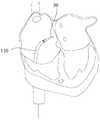
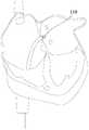
- an adjustable curved sheath tube 100 of an embodimentincludes a tubular body portion 110 and an operating mechanism 150 for operating the tubular body portion 110.
- the tubular body portion 110includes an outer tube 112, an inner tube 113, a developing member 115, a sliding tube 116, and a pulling wire 117.
- the outer tube 112includes a connecting tube 1121 and a tube body (not labeled) communicating with the connecting tube 1121.
- the connection tube 1121has a higher hardness than the tube body.
- the connecting tube 1121is coaxial with the tubular body.
- the tubular bodyincludes a first tubular section 1123 and a second tubular section 1125.
- One end of the first tubular section 1123is fixed to one end of the connecting tube 1121.
- One end of the second tubular section 1125is fixed to an end of the first tubular section 1123 away from the connecting tube 1121, and the first tubular section 1123 and the second tubular section 1125 are both flexible. That is, the first tubular section 1123 and the second tubular section 1125 are portions in which the tubular body has flexibility.
- the three sections of the second tubular section 1125, the first tubular section 1123, and the connecting tube 1121are sequentially increased in hardness.
- the second tubular section 1125, the first tubular section 1123, and the connecting tube 1121are nylon elastomer (PEBAX) tubes of different hardnesses. Further, the hardness of the second tubular section is 30D to 40D. Further, the material of the second tubular section 1125 is 35D PEBAX, the material of the first tubular section 1123 is 55D PEBAX, and the material of the connecting tube 1121 is 72D PEBAX.
- PEBAXnylon elastomer
- the first tubular section 1123 and the second tubular section 1125are flexible such that bending can occur when the first tubular section 1123 and the second tubular section 1125 are subjected to a force.
- the first tubular section 1123 and the second tubular section 1125have a bending angle of 0° to 180°, preferably 90°, so that the first tubular section 1123 can be controlled according to the lengths of the first tubular section 1123 and the second tubular section 1125.
- the radius of curvature of the second tubular section 1125when the adjustable curved sheath 100 is applied to a blood vessel or a heart, the desired bending angle can be designed according to the actual vascular or cardiac anatomy to determine the first tubular section 1123 and The length of the second tubular section 1125.
- the first tubular section 1123has a length of 30 mm to 70 mm and the second tubular section 1125 has a length of 20 mm to 40 mm.
- the inner tube 113is housed in the outer tube 112 and adheres to the inner wall of the outer tube 112.
- the inner tube 113is coaxial with the outer tube 112.
- the inner wall of the inner tube 113is a smooth surface to ensure smooth transportation of other instruments.
- the material of the inner tube 113is polytetrafluoroethylene (PTFE).
- the material of the inner tube 113may also be polyethylene terephthalate (PET), of course.
- PETpolyethylene terephthalate
- the material of the inner tube 113is not limited to PTFE or PET, and other materials which can ensure the inner wall of the inner tube 113 are smooth.
- the inner tube 113can be omitted, as long as the inner wall of the outer tube 112 is smooth to ensure smooth transportation of other instruments.
- an inner membranecan be formed on the inner surface of the outer tube 112.
- the materialis selected from at least one of PTFE and PET.
- the inner filmcan be prepared by coating or the like as long as the inner wall of the outer tube 112 is made smooth.
- the developing member 115is located at one end of the second tubular section 1125 away from the first tubular section 1123.
- the developing member 115is a developing ring, and the developing member 115 is sleeved and fixed to the outer wall of the inner tube 113, and is fixed to the outer tube 112 by heat fusion. Further, the developing member 115 is coaxial with the outer tube 112.
- the developing member 115is not limited to being a developing ring, and a developing coating layer may be formed on the inner wall of the outer tube 112 or the outer wall of the inner tube 113 by coating or the like as long as it can function as an X-ray developing.
- the material of the developing member 115is selected from at least one of ruthenium and platinum.
- the sliding tube 116is located between the inner tube 113 and the outer tube 112.
- the sliding tube 116extends from an end of the second tubular section 1125 away from the first tubular section 1123 to an end of the connecting tube 1121 away from the first tubular section 1123.
- the outer tube 112is formed with a receiving passage (not shown), and the sliding tube 116 is received in the receiving passage.
- the sliding tube 116 wearing the supporting wireis fixed to the outer wall of the inner tube 113 by medical glue, and the outer tube 112 is sheathed, and all materials are thermally fused together by heating, due to
- the sliding tube 116is internally provided with a supporting wire so that the sliding tube 116 is embedded in the outer tube 112 during heat fusion, thereby forming a receiving passage in the outer tube 112.
- the tubular portion 110further includes a reinforcing tube (not shown) that is embedded in the outer tube 112, and the reinforcing tube is sleeved on the surfaces of the inner tube 113 and the sliding tube 116.
- the reinforcing tubeis a stainless steel braided mesh tube or a stainless steel spring tube. After the sliding tube 116 wearing the supporting wire is fixed to the outer wall of the inner tube 113 by the medical glue, the reinforcing tube is sleeved on the surface of the inner tube 113 and the sliding tube 116, and the outer tube 112 is placed and then heated by heating. The materials are hot melted together.
- the material of the sliding tube 116is polytetrafluoroethylene (PTFE).
- PTFEpolytetrafluoroethylene
- the material of the inner tube 113is not limited to PTFE, as long as the inner wall of the sliding tube 116 can be made smooth. It can be understood that the sliding tube 116 can be omitted when the outer tube 112 forms a smooth receiving passage.
- one end of the pulling wire 117is disposed on the sliding tube 116 and is fixed to the developing member 115 .
- the pulling wire 117is a wire, and preferably the material of the pulling wire 117 is a nickel titanium alloy.
- the material of the pulling wire 117is not limited to a nickel-titanium alloy, and as long as the tensile strength is high, the pulling function can be achieved.
- One end of the pulling wire 117is fixed to the developing member 115 by welding.
- an anchoring ring fixed to the outer tube 112may be disposed in the outer tube 112 to fix one end of the pulling wire 117, or one end of the pulling wire 117 may be bonded or the like. Directly fixed to the outer tube 112.
- the pulling wire 117extends from the end of the second tubular section 1125 away from the first tubular section 1123 along the sliding tube 116, and the free end of the pulling wire 117 extends out of the sliding tube 116 to connect the operating mechanism 150.
- the pulling wire 117extends from the end of the second tubular section 1125 away from the first tubular section 1123 toward the end of the first tubular section 1123 away from the second tubular section 1125 along the cylindrical surface of the inner tube 113.
- the extension curve of the pulling wire 117is a smooth curve to facilitate the pulling force on the pulling wire 117 to slide the pulling wire 117 relative to the sliding tube 116.
- the pulling wire 117extends straight from one end of the connecting pipe 1121 near the first tubular section 1123 toward an end away from the first tubular section 1123.
- the portion of the pulling wire 117 extending in the first tubular section 1123is orthographically projected in a plane perpendicular to the axis of the first tubular section 1123. It is an arc with a circumferential angle of ⁇ .
- ⁇is from 0° to 180°, further 0°.
- the pulling wire 117extends linearly in the first tubular section 1123.
- the orthographic projection of the portion of the pulling wire 117 extending in the second tubular portion 1125 in a plane perpendicular to the axis of the second tubular portion 1125is a circumferential angle.
- the arc of ⁇ . ⁇is 0° to 180°, and more preferably 90°.
- the operating mechanism 150includes a connector 151 , an operating handle 153 , and an operating member 155 .
- the connecting member 151is fixed to the end of the connecting tube 1121 of the outer tube 112 away from the tubular body.
- the connecting member 151is substantially tubular, and is sleeved on the connecting tube 121 and fixed to the connecting tube 121.
- One end of the operating handle 153is connected to the connecting member 151, and is disposed obliquely with respect to the connecting member 151 to facilitate gripping.
- the operating member 155is provided on the joystick 153 and slidable relative to the operating handle 153 in a direction away from or near the connecting member 151.
- the free end of the pulling wire 117is fixed to the operating member 155 of the operating mechanism 150, so that sliding the operating member 155 away from the connecting member 151 can transmit the traction force to the pulling wire 117.
- the pulling of the pulling wire 117 by the sliding of the operating member 155 of the operating mechanism 150is only one of the modes, and the pulling wire 117 can also be controlled by other operating mechanisms, such as by rotating.
- the pulling wire 117is tightened in such a manner that the pulling wire 117 can be slid relative to the outer tube 112 as long as a pulling force can be applied to the pulling wire 117.
- a pulling forceis applied to the pulling wire 117 through the operating member 155 of the operating mechanism 150.
- the forceis transmitted to the developing member 115, and the developing member 115 is located in the second tubular portion.
- 1125is away from one end of the first tubular section 1123, so that the traction force is applied to the end of the second tubular section 1225.
- the second tubular section 1225is unilaterally biased away from the end of the first tubular section 1123, and the bending is biased toward the direction of the force.
- the hardness of the first tubular section 1123is greater than that of the second tubular section 1125, so that when the force transmitted by the pulling wire 117 is within a certain range, the first tubular section 1223 does not deform, and the force transmitted by the pulling wire 117 is greater than At a certain value, the first tubular section 1223 also bends as the traction wire 117 follows the end of the second tubular section 1123 away from the first tubular section 1123 toward the first tubular section 1123 away from the second tubular section 1125 along the inner tube.
- the cylindrical surface of 113extends in a spiral curve such that the first tubular section 1123 is adjacent to the end of the second tubular section 1125 and the second tubular section 1125 is remote from the section of the first tubular section 1123.
- the first tubular section 1223 and the second tubular section 1125can generate a multistage counter-bending effect, because of the greater hardness of the connection tube 1121 is within a certain range of tensile force, the connection tube 1121 is not deformed to maintain a straight shape.
- the tubular body portion 110 of the adjustable curved sheath tube 100is configured to have a flexible first tubular section 1223 and a second tubular section 1225.
- a pulling forceis applied to the pulling wire 117 through the free end of the pulling wire 117.
- the other end of the wire 117is fixed to the tube body, and the pulling wire 117 is slidable relative to the first tubular section 1223 and the second tubular section 1225 to apply a pulling force to the tubular body. Since the first tubular section 1223 and the second tubular section 1225 are flexible, It will bend in the direction of the force, thus achieving multi-segment bending, which can better meet the clinical use requirements and has strong applicability.
- the pipe bodyis not limited to a two-stage structure, and may also be a three-stage or three-stage structure. As long as the control pipe body is increased in hardness from the connecting pipe 1121 to the connecting pipe 1121, the hardness of each pipe body increases sequentially. Just fine.
- the structure of the adjustable curved sheath tube of the other embodimentis substantially the same as that of the adjustable curved sheath tube 100 .
- the differenceis that the structure of the tubular body portion is slightly different from the tubular body portion 110.
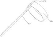
- the pulling wire 217 of the tubular portionis folded around the developing member 215 to form a bent portion 2172, and the edge of one end of the developing member 215 abuts against the bent portion 2172. In use, both ends of the pulling wire 217 are free ends, and both ends of the pulling wire 217 are simultaneously connected to the operating mechanism.
- the pulling wire 217is folded in half to form the bent portion 2172.
- the pulling wire 217may be wound around the developing member 215 at least once to form the bent portion 2172.
- the pulling wireis fixed by the anchoring ring, and the pulling wire 217 is folded to form a bent portion 2172, and an edge of one end of the anchoring ring abuts the bent portion 2172 Just fine.
- the adjustable curved sheath tube having the above structuredoes not need to be welded to fix the pulling wire 217 to the developing member 215, so that the material of the pulling wire 217 is more widely selected, and the material of the anchoring ring is fixed when the pulling wire is fixed by the anchoring ring. Choose more.
- the traction wireis fixed in the above manner, and the connection manner of the traction wire is similar to the flexible connection, and the connection strength and connection stability with the developing member 215 or the anchor ring are higher; it is easier to prepare without welding.
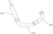
- the adjustable curved sheath tube 300 of another embodimenthas substantially the same structure as the adjustable curved sheath tube 100, and the difference is that the traction wire of the tubular body portion 310 of the adjustable curved sheath tube 300 is The first traction wire 3171 and the second traction wire 3173 are included.
- two developing membersare respectively a first developing member 314 and a second developing member 315.
- the operating mechanism 350includes a first operating member 3551 and a second operating member. 3553.
- the first developing member 314is located at one end of the first tubular section 3123 adjacent to the second tubular section 3125, and the second developing member 315 is located at an end of the second tubular section 3125 away from the first tubular section 3123.
- the first traction wire 3171extends linearly in a direction parallel to the axis of the first tubular section 3123.
- the first traction wire 3171extends in a spiral curve about the axis of the first tubular section 3123 to an end of the first tubular section 3123 adjacent the connecting tube 3121.
- the second pulling wire 3175extends straight in a direction parallel to the axis of the first tubular section 3123.
- the first traction wire 3171extends in a spiral curve about the axis of the first tubular section 3123 and the second tubular section 3125 to an end of the first tubular section 3123 adjacent to the connecting tube 3121.
- the plane of the first traction wire 3171 and the axis of the first tubular section 3123 and the plane of the second traction wire 3173 and the axis of the first tubular section 3123form an angle ⁇ .
- ⁇is from 0° to 180°, and further preferably from 90°.
- the adjustable bending sheath tube 300when the adjustable bending sheath tube 300 is in use, a pulling force is applied to the second pulling wire 3173 by the operating mechanism 350, and after the second pulling wire 3173 is subjected to the pulling force, the force is transmitted to the first
- the second developing member 315is located at one end of the second tubular section 3125 away from the first tubular section 3123, thereby applying a traction force to the end of the second tubular section 3125, and the second tubular section 3125 is away from the first tubular section 3123.
- the bendingis biased toward the direction of the force; the pulling force is applied to the first pulling wire 3171 by the operating mechanism 350, and the first pulling wire 3171 is subjected to the pulling force, and then the force is transmitted to the first developing member 314.
- a developing member 314is located at one end of the first tubular section 3123 near the second tubular section 3125, thereby applying a traction force to the end of the first tubular section 3123, and the end of the first tubular section 3125 is unilaterally biased to be biased toward the direction of the force. , the effect of multi-section anisotropic bending. By controlling the angle ⁇ , the direction of the anisotropic bending can be controlled.
- first tubular section 3171 and the second tubular section 3125are controlled to be bent by the first pulling wire 3171 and the second pulling wire 3173, the hardness of the first tubular section 3123 and the second tubular section 3125 is not particularly required. .
- the three sections of the second tubular section 3125, the first tubular section 3123, and the connecting tube 3121are sequentially increased in hardness to facilitate handling.
- the adjustable curved sheath tube of another embodimentis substantially identical in construction to the adjustable curved sheath tube 100, with the following differences:
- the second tubular section 4125 of the tubular body portion 410has flexibility.
- the first tubular section 4123has a rigid and curved shape, and the pulling wire 417 can drive the second tubular section 4125 to bend. That is, the second tubular section 4125 is a portion in which the tubular body has flexibility. In the natural state, the first tubular section 4123 is in a bent state. At this time, in order to facilitate the bending of the second tubular section 4125 by the pulling wire 417, the connection point of the pulling wire 417 and the developing member 415 is located on one side of the bending direction of the second tubular section 4125.
- the first tubular section 4123is curved by a shaping process to provide a fixed angle.
- the hardness of the second tubular section 4125is smaller than the hardness of the first tubular section 4123 and the connecting tube 4121.
- the second tubular section 4125is made of a polymer material pipe having a small coefficient of friction, excellent folding resistance and excellent twist control, such as a nylon elastomer (PEBAX) tube.
- PEBAXnylon elastomer
- the second tubular section 4125has a hardness of 30D to 40D; the first tubular section 4123 has a hardness of 65D to 75D; and the connecting tube 4121 has a hardness of 65D to 75D.
- the second tubular section 4125, the first tubular section 4123 and the connecting tube 4121are joined together by hot melt.
- the second tubular section 4125is flexible, bending can occur when the second tubular section 4125 is subjected to a force.
- the second tubular section 4125has a bend angle of 0 to 180° and the first tubular section has a bend angle of 25° to 65°.
- the radius of curvature of the first tubular section 4123 and the second tubular section 4125can be controlled according to the lengths of the first tubular section 4123 and the second tubular section 4125 to accommodate different blood vessels and anatomical structures of the heart, or the tubular body
- the required bending anglecan be designed according to the actual blood vessel or the anatomy of the heart to determine the lengths of the first tubular section 4123 and the second tubular section 4125.
- the plane of the second tubular section 4125is between 0° and 360°, and further 70° to 110°, with the plane of the first tubular section 4123.
- the angle formed by the plane of the second tubular section 4125 and the plane of the first tubular section 4123can also be adjusted according to the actual vascular or cardiac anatomy.
- a pulling forceis applied to the pulling wire 417 by the operating mechanism, and after the pulling wire 417 is subjected to the pulling force, the force is transmitted to the developing member 415, and the developing member 415 is located at the second tubular portion 4125 away from the first tubular shape.
- One end of the segment 4123, thereby applying a traction force to the end of the second tubular section 4125, and the second tubular section 4125is unilaterally biased away from the end of the first tubular section 4123, and is deflected in a biased direction.
- the first tubular section 4123 of the tubular body portion 410 of the adjustable curved sheath of the present embodimenthas a rigid and curved shape
- the second tubular section 4125is flexible and capable of being bent by force, and for a vascular passage having a small structural difference, For example, in the left atrium and the right atrium, most of the structures and angles formed are relatively uniform.
- the structure of the tube 410 of the adjustable curved sheath tube of the present embodimentnot only satisfies the clinical use, but also has more convenient operation and simpler production and preparation.
- the adjustable curved sheath tube of another embodimentis substantially identical in construction to the adjustable curved sheath tube 100, with the following differences:
- the second tubular section 5125 of the tubular body portion 510is rigid and curved, the first tubular section 5123 is flexible, and the pulling wire 517 can drive the first tubular section 5123 to bend. That is, the first tubular section 5123 is a portion in which the tubular body has flexibility. In the natural state, the second tubular section 5125 is in a bent state. In one of the embodiments, the second tubular section 5125 is curved by a shaping process to provide a fixed angle. At this time, the developing member 515 is located at one end of the first tubular section 5123 near the second tubular section 5125. In order to facilitate the pulling of the first tubular section 5123 by the pulling wire 517, the connection point of the pulling wire 517 and the developing member 515 is located on one side of the bending direction of the first tubular section 5123.
- the hardness of the first tubular section 5123is smaller than that of the second tubular section 5125 and the connecting tube 5121.
- the first tubular section 5123, the second tubular section 5125 and the connecting tube 5121are joined together by hot melt.
- the first tubular section 5123is made of a polymer material tube having a small coefficient of friction, excellent folding resistance and excellent twist control, such as a nylon elastomer (PEBAX) tube.
- PEBAXnylon elastomer
- the first tubular section 5123has a hardness of 30D to 40D
- the second tubular section 5125has a hardness of 65D to 75D
- the connecting tubehas a hardness of 65D to 75D.
- first tubular section 5123is flexible, bending can occur when the first tubular section 5123 is subjected to a force.
- first tubular section 5123has a bend angle of 0-180° and the second tubular section 5125 has a bend angle of 70°-110°.
- the radius of curvature of the first tubular section 5123 and the second tubular section 5125can be controlled according to the lengths of the first tubular section 5123 and the second tubular section 5125 to accommodate different blood vessels and anatomical structures of the heart, or the tubular body
- the required bending anglecan be designed according to the actual vascular or cardiac anatomy to determine the length of the first tubular section 5123 and the second tubular section 5125.
- the plane in which the first tubular section 5123 is locatedis between 0° and 360°, and further 70° to 110°, in the plane in which the second tubular section 5125 is located.
- the angle formed by the plane of the first tubular section 5123 and the plane of the second tubular section 5125can also be adjusted according to the actual vascular or cardiac anatomy.
- a pulling forceis applied to the pulling wire 517 by the operating mechanism, and after the pulling wire 517 is subjected to the pulling force, the force is transmitted to the developing member 515, and the developing member 515 is located at the first tubular section 5123 near the second tubular shape.
- One end of the segment 5125so that the traction force is applied to one end of the first tubular segment 5123 near the second tubular segment 5125, and the first tubular segment 5123 is unilaterally biased near the end of the second tubular segment 5125, and the bending is biased toward the direction of the force.
- the first tubular section 5123 of the tubular portion 510 of the adjustable curved sheath of the present embodimenthas flexibility to be flexibly bent, and the second tubular section 5125 has a rigid and curved shape, and for a vascular passage having a small structural difference,
- the structure of the tubular body portion 510 of the adjustable curved sheath tube of the present embodimentnot only satisfies the clinical use, but also has more convenient operation and simpler production and preparation.
- the tube bodyis not limited to a two-stage structure, and may also be a three-stage and three-stage structure, that is, the number of the first tubular section 5123 and the second tubular section 5125 is not limited to each one, and the first tubular section 5123
- the number of the second tubular segments 5125can be adjusted as needed.
- the number of the pulling wires 517can also be correspondingly increased according to the number of segments in which the tubular body has flexibility.
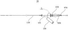
- a medical device 20 of an embodimentincludes the above-described adjustable curved sheath tube 100 and an expansion puncturing device.
- the structure of the adjustable bending sheath 100is as shown in FIGS. 1 to 7 .
- the expansion piercing deviceincludes an expansion assembly 800 and a piercing assembly 900.
- the expansion assembly 800includes a dilation tube 810 and a closure member 830.
- one end of the dilation tube 810is provided with a joint 815.
- the joint 815includes an operation portion 8151, a lock portion 8153, and a fitting portion 8155.
- the operation portion 8151has a cylindrical shape and has a diameter larger than that of the operation portion 8151 and the fitting portion 8155 to facilitate the gripping operation.
- the lock portion 8153is connected to one end of the operation portion 8151 and is connected to the expansion tube 810.
- the mounting portion 8155is connected to the other end of the operating portion 8151.
- the operating portion 8151, the locking portion 8153, the mounting portion 8155, and the expansion tube 810are integrally formed.
- the operation portion 8151, the lock portion 8153, and the fitting portion 8155are provided with through holes communicating with the expansion tube 810 for insertion of the puncture needle 930 of the puncture assembly 900.
- the locking member 830is sleeved on the locking portion 8153 and fixedly connected to the locking portion 8153.
- the latch 830can be fixedly coupled to the operating mechanism 150.
- the locking member 830is a locking cap formed with an internal thread
- an end of the connecting member 151 of the operating mechanism 150 away from the tubular portion 110is formed with an engaging portion 1512 (shown in FIG. 1).
- the engaging portion 1512is an external thread formed on the surface of the connecting member 151 so as to be assembled with the locking member 830.
- the engaging member 830may be disposed outside the surface of the locking member 830.
- the threading memberis provided with a matching internal thread on the connecting member 151.
- the locking member 830 and the connecting member 151can also be connected by other means such as snapping.
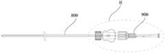
- the piercing assembly 900includes a handle 910, a puncture needle 930, a connector 950, and an adjustment member 970.
- the handle 910is generally cylindrical.
- the handle 910is provided with a sliding slot 912 and a positioning slot 914.
- the chute 912is recessed inwardly from the outer surface of the handle 910 and extends along the length of the handle 910.
- the positioning groove 914is in communication with the chute 912 and extends in the axial direction of the handle 910.
- the positioning slots 914are plural, and the plurality of positioning slots 914 are arranged along the axial direction of the handle 910.
- the axial arrangement along the handle 910refers to a general direction.
- all of the positioning slots 914are located on one side of the sliding slot 912.
- the partial positioning slot 914is located in the sliding slot.
- On one side of the 912a portion of the positioning groove 914 is located on the other side of the chute 912, and is understood to be arranged in the axial direction.
- the adjustment member 970is generally cylindrical.
- the adjusting member 970is sleeved on the handle 910, and the inner wall of the adjusting member 970 is provided with a protrusion 972 that can cooperate with the sliding slot 912 and the positioning groove 914.
- the protrusion 972 of the adjusting member 970can slide along the sliding slot 912, and the position of one of the positioning slots 914 rotates the adjusting member 970, and the protrusion 972 can slide to the positioning groove 914 for positioning.
- an external threadmay be disposed on the surface of the handle 910, and an internal thread is disposed on the adjusting member 970 to adjust and position the adjusting member 970 and the handle 910 by rotating.
- the limiting portion 916is a boss formed on the handle 910 and partially received in the sliding slot 912. Further, the limiting portion 916 is a wedge-shaped boss and the number is two, and is symmetrically disposed along the circumference of the handle 910. In other embodiments, the limiting portion 916 can also be a structure such as a convex ring. In some embodiments, the limiting portion 916 can also be a nut screwed to one end of the handle 910 to facilitate assembly of the connecting member 950. In short, as long as the connector 950 can be prevented from falling off the handle 910.
- the end of the handle 910 away from the limiting portion 916is formed with an external thread 918 to facilitate docking with other components.
- One end of the puncture needle 930is inserted into one end of the handle 910 where the limiting portion 916 is disposed.
- the puncture needle 930can be housed in the dilation tube 810.
- the connector 950includes a resisting portion 952 and a connecting portion 954 .
- the connecting portion 954is substantially cylindrical and can be sleeved on the handle 910.
- the abutting portion 952is a convex ring that is convexly provided on the inner wall of the connecting portion 954. In the illustrated embodiment, the abutting portion 952 protrudes inwardly from one end of the connecting portion 954.
- the inner diameter of the abutting portion 952is slightly larger than the outer diameter of the handle 910 and can be blocked by the limiting portion 916, thereby making the connection
- the piece 950can slide relative to the handle 910 and cannot be disengaged from the end of the handle 910 where the abutment portion 952 is disposed.
- the fitting portion 8155is formed with an external thread
- the connecting portion 954can be sleeved on the fitting portion 8155 and provided with an internal thread that cooperates with the external thread of the fitting portion 8155, thereby connecting the connecting member 950 by screwing the connecting portion 954 with the fitting portion 8155. It is assembled with the joint 815.
- the internal threadmay be formed on the mounting portion 8155, and the external thread corresponding to the connecting portion 954 may be formed correspondingly, and the two may be fixed by other means such as engagement.
- the adjusting member 970is slid along the handle 910 toward the positioning groove 914 of the limiting portion 916 and positioned to abut the connecting member 950, and the puncture needle 930 is inserted into the expansion tube 810 to be connected.
- the connecting portion 954 of the member 950is sleeved on the mounting portion 8155 and screwed into the mounting portion 8155.
- the puncture needle 930is housed in the dilating tube 810, and the dilating and puncture device is assembled.
- the expansion tube 810is inserted into the tubular body portion 110 from the connector 151, and the closure member 830 is screwed with the engagement portion 1512 to assemble the expansion assembly 800 to the tubular body portion 110.
- a short puncture vascular guide wireis inserted into the body through the femoral vein, and then the vascular sheath is inserted into the blood vessel along the short puncture vascular guide wire.
- the short puncture of the vascular guidewireis withdrawn, and the puncture of the vascular sheath is retained to maintain and maintain the instrument exchange and hemostasis.
- the vascular guide wire 30 of the "J"-shaped tipenters the right atrium through the femoral vein and the inferior vena cava, and the vascular guide wire remains in the body, and the puncture vessel sheath is withdrawn.
- the adjustable curved sheath tube 100 assembled with the expansion puncturing deviceis inserted and pushed until the distal end of the tubular body portion 110 is in the right atrium (as shown in Fig. 22). Out of the blood vessel guide wire.
- the tubular body portion 110is slowly urged and maintains the expansion puncture device in a relatively fixed position relative to the tubular body portion 110 to prevent relative changes in position of the components until the distal end of the tubular body portion 110 reaches the appropriate punctured fossa ovalis.
- the position of the adjustment member 970is adjusted such that the adjustment member 970 is slid and positioned proximally, and the handle 910 is gently pushed to push the puncture needle 930 from the distal end of the dilation tube 810 to extend to the right atrium fossa.
- Pushing the handle 910continues to allow the tip of the puncture needle 930 to pass through the interatrial septum into the left atrium (LA) (Fig. 23). While maintaining the position of the puncture needle 930 in the left atrium, the expansion assembly 800 and the body portion 110 are introduced into the left atrium along the puncture needle 930. After the distal end of the tubular body portion 110 is integrally accessed, the position of the adjusting member 970 is adjusted, and the adjusting member 970 is slid and positioned to the connecting member 950, so that the puncture needle 930 is retracted into the inside of the dilating tube 810, and then the dilating and puncture device is withdrawn, and the tube body is retained. Part 110 is in the left atrium (Fig. 24), establishing a passage from the body to the body.
- the operating mechanism 150(as in Figures 1-7) is manipulated such that the distal end of the tubular portion 110 is aligned with the entrance position of the left atrial appendage. That is, a pulling force is applied to the pulling wire 117 by the operating member 155 of the operating mechanism 150. After the pulling wire 117 is subjected to the pulling force, the force is transmitted to the developing member 115, and the developing member 115 is located at the end of the second tubular portion 1125 away from the first tubular portion 1123.
- the traction forceis applied to the end of the second elastic segment 1225, and the second elastic segment 1225 is unilaterally biased away from the end of the first tubular segment 1123, and the bending is biased toward the direction of the force, and at the same time, the hardness of the first tubular segment 1123
- the second tubular section 1125is larger than the second tubular section 1125, so that when the force transmitted by the pulling wire 117 is within a certain range, the first tubular section 1223 is not deformed, and when the force transmitted by the pulling wire 117 is greater than a certain value, the first tubular section 1223 Bending also occurs as the traction wire 117 extends along the cylindrical surface of the inner tube 113 along one end of the second tubular section 1125 away from the first tubular section 1123 toward the first tubular section 1123 away from the second tubular section 1125.
- first tubular section 1123is adjacent to the end of the second tubular section 1125 and the second tubular section 1125 is different from the direction of the tensile force experienced by the section of the first tubular section 1123, thus the first tubular section 12 23 and the second tubular section 1125 can produce a multi-section anisotropic bending effect. Because the hardness of the connecting tube 1121 is larger, the connecting tube 1121 does not deform and maintain a straight shape within a certain tensile force range.
- proximal end and the distal end mentioned in the above embodimentsare determined by the position at the time of use, the position close to the operator is the proximal end, and the distance from the operator is the distal end.
- the puncture needle 930can simultaneously perform the function of puncturing and establishing the track, and the tube body portion 110 need not be replaced in the middle; and the adjusting member 970 and the limiting portion 916 are controlled by adjusting the position of the adjusting member 970 at the position of the handle 910.
- the distance between the handle 910 and the expansion assembly 800can be precisely controlled, and the length of the puncture needle 930 from the dilation tube 810 can be controlled to precisely control the penetration depth.
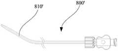
- the expansion tube 810is a straight tube.
- the expansion tube 810' of the expansion assembly 800'is an elbow, a dilation tube. The end of the 810' is bent and extended. Since the puncture needle has elasticity, when the dilation tube 810 is inserted, the dilation tube 810 can be bent.
- the structure of the adjustable curved sheath tube 100 of the medical device 20is not limited to the above structure.
- the adjustable curved sheath tube of the medical devicemay also have the corresponding structure shown in FIGS. 8-13.
- the above-mentioned medical deviceis only one of the application methods of the adjustable curved sheath tube, and the above-mentioned adjustable curved sheath tube can be applied as long as the medical instrument requiring multiple segments of the opposite bending is required.
Landscapes
- Health & Medical Sciences (AREA)
- Life Sciences & Earth Sciences (AREA)
- Biophysics (AREA)
- Pulmonology (AREA)
- Engineering & Computer Science (AREA)
- Anesthesiology (AREA)
- Biomedical Technology (AREA)
- Heart & Thoracic Surgery (AREA)
- Hematology (AREA)
- Animal Behavior & Ethology (AREA)
- General Health & Medical Sciences (AREA)
- Public Health (AREA)
- Veterinary Medicine (AREA)
- Media Introduction/Drainage Providing Device (AREA)
Abstract
Description
Translated fromChinese本发明涉及医疗器械领域,特别是涉及一种可调弯鞘管和医疗器械。The present invention relates to the field of medical devices, and more particularly to an adjustable curved sheath tube and a medical device.
可调弯鞘管已广泛应用于微创介入诊断和治疗手术中,用于建立通道,输送或回收器械、输入药物或导出体液。相比普通鞘管,鞘管具有可调弯功能,通过远端的自由调弯,可以快速、可靠的达到靶病变位置,以减少手术时间。Adjustable curved sheath has been widely used in minimally invasive interventional diagnostic and therapeutic procedures to establish channels, deliver or retrieve instruments, import drugs or export body fluids. Compared with the ordinary sheath tube, the sheath has an adjustable bending function, and the freely adjusted bending at the distal end can quickly and reliably reach the target lesion position, thereby reducing the operation time.
目前,市场上可调弯鞘管仅是头端的1段可以进行调弯,但可调弯鞘管的头端以下外管为非弯曲状态;或者鞘管的远端具有2段不同弯曲方向的固定弯。At present, the adjustable elbow sheath on the market is only one end of the head end can be adjusted, but the outer tube below the head end of the adjustable curved sheath tube is in a non-bent state; or the distal end of the sheath tube has two different bending directions Fixed bend.
针对于多段弯曲的血管通路,仅可调弯鞘管的头端弯曲并不能完全满足临床使用要求,难以适用于所有的患者。For the multi-segmented vascular access, only the curved end of the adjustable sheath can not fully meet the clinical requirements, and it is difficult to apply to all patients.
发明内容Summary of the invention
基于此,有必要提供一种适用性较强的可调弯鞘管。Based on this, it is necessary to provide a flexible curved sheath tube with high applicability.
此外,还提供一种医疗器械。In addition, a medical device is also provided.
一种可调弯鞘管,包括管体部分,所述管体部分包括:An adjustable curved sheath tube comprising a tubular body portion, the tubular body portion comprising:
外管,包括连接管及与所述连接管连通的管身,所述管身包括第一管状段及第二管状段,所述第一管状段与所述连接管固接,所述第二管状段与所述第一管状段远离所述连接管的一端固接,所述第二管状段及所述第一管状段中的至少一个具有柔性,且所述第二管状段及所述第一管状段中的一个具有柔性时,另一个具有刚性且呈弯曲状;及The outer tube includes a connecting tube and a tube body communicating with the connecting tube, the tube body including a first tubular section and a second tubular section, the first tubular section being fixed to the connecting tube, the second The tubular section is fixed to an end of the first tubular section away from the connecting tube, at least one of the second tubular section and the first tubular section has flexibility, and the second tubular section and the first One of the tubular segments is flexible and the other is rigid and curved;
牵引丝,与所述管身固接,所述牵引丝沿所述外管延伸,且所述牵引丝 的自由端延伸出所述连接管远离所述管身的一端,所述牵引丝相对所述管身可滑动,并能够带动所述管身具有柔性的部分产生弯曲。Traction wire fixed to the tube body, the traction wire extends along the outer tube, and the free end of the traction wire extends out of the end of the connecting tube away from the tube body, the traction wire is opposite The tubular body is slidable and can drive the flexible portion of the tubular body to bend.
一种医疗器械,包括上述可调弯鞘管。A medical device comprising the above-mentioned adjustable curved sheath tube.
本发明的一个或多个实施例的细节在下面的附图和描述中提出。本发明的其它特征、目的和优点将从说明书、附图以及权利要求书变得明显。Details of one or more embodiments of the invention are set forth in the accompanying drawings and description below. Other features, objects, and advantages of the invention will be apparent from the description and appended claims.
为了更清楚地说明本发明实施例或现有技术中的技术方案,下面将对实施例或现有技术描述中所需要使用的附图作简单地介绍,显而易见地,下面描述中的附图仅仅是本发明的一些实施例,对于本领域普通技术人员来讲,在不付出创造性劳动的前提下,还可以根据这些附图获得其他实施例的附图。In order to more clearly illustrate the embodiments of the present invention or the technical solutions in the prior art, the drawings used in the embodiments or the description of the prior art will be briefly described below. Obviously, the drawings in the following description are only It is a certain embodiment of the present invention, and those skilled in the art can obtain drawings of other embodiments according to the drawings without any creative work.
图1为一实施方式的可调弯鞘管的结构示意图;1 is a schematic structural view of an adjustable curved sheath tube according to an embodiment;
图2为图1所示的可调弯鞘管的管体部分的局部结构示意图;Figure 2 is a partial structural schematic view of the tubular body portion of the adjustable curved sheath tube shown in Figure 1;
图3为图1所示的可调弯鞘管的管体部分的局部剖面图;Figure 3 is a partial cross-sectional view of the tubular body portion of the adjustable curved sheath tube of Figure 1;
图4为图3的局部放大图;Figure 4 is a partial enlarged view of Figure 3;
图5为图1所示的可调弯鞘管的管体部分的局部结构示意图;Figure 5 is a partial structural schematic view of the tubular body portion of the adjustable curved sheath tube shown in Figure 1;
图6为图1所示的可调弯鞘管的管体部分的显影件和牵引丝的结构示意图;Figure 6 is a structural schematic view of the developing member and the pulling wire of the tubular body portion of the adjustable curved sheath tube shown in Figure 1;
图7为图1所示的可调弯鞘管的管体部分处于弯曲状态的示意图;Figure 7 is a schematic view showing the tubular body portion of the adjustable curved sheath tube shown in Figure 1 in a bent state;
图8为另一实施方式的可调弯鞘管的管体部分的显影件和牵引丝的结构示意图;8 is a schematic structural view of a developing member and a pulling wire of a tubular body portion of an adjustable curved sheath tube according to another embodiment;
图9为另一实施方式的可调弯鞘管的结构示意图;9 is a schematic structural view of an adjustable curved sheath tube according to another embodiment;
图10为图9所示的可调弯鞘管的管体部分的局部结构示意图;Figure 10 is a partial structural schematic view of the tubular body portion of the adjustable curved sheath tube shown in Figure 9;
图11为图9所示的可调弯鞘管的管体部分处于弯曲状态的示意图;Figure 11 is a schematic view showing the tubular body portion of the adjustable curved sheath tube shown in Figure 9 in a bent state;
图12为图9所示的可调弯鞘管的管体部分处于另一种弯曲状态的示意图;Figure 12 is a schematic view showing the tubular body portion of the adjustable curved sheath tube shown in Figure 9 in another curved state;
图13为图9所示的可调弯鞘管的管体部分处于又一种弯曲状态的示意 图;Figure 13 is a schematic view showing the tubular body portion of the adjustable curved sheath tube shown in Figure 9 in a further curved state;
图14为另一实施方式的可调弯鞘管的管体部分的局部结构图;Figure 14 is a partial structural view of a tubular body portion of an adjustable curved sheath tube according to another embodiment;
图15为另一实施方式的可调弯鞘管的管体部分的局部结构图;Figure 15 is a partial structural view of a tubular body portion of an adjustable curved sheath tube of another embodiment;
图16为一实施方式的医疗器械的结构示意图;16 is a schematic structural view of a medical device according to an embodiment;
图17为图16所示的医疗器械的扩张穿刺装置的结构示意图;Figure 17 is a schematic view showing the structure of the expansion and puncture device of the medical device shown in Figure 16;
图18为图17所示的扩张穿刺装置处于另一种状态的结构示意图;Figure 18 is a schematic view showing the structure of the expansion and puncture device shown in Figure 17 in another state;
图19为图17的II部的局部放大图;Figure 19 is a partial enlarged view of a portion II of Figure 17;
图20为图17所示的扩张穿刺装置的穿刺组件的部分结构示意图;Figure 20 is a partial structural schematic view of the puncture assembly of the expansion puncture device shown in Figure 17;
图21为沿图20的III-III线的剖视图;Figure 21 is a cross-sectional view taken along line III-III of Figure 20;
图22为图16所示的医疗器械远端进入右心房的位置示意图;Figure 22 is a schematic view showing the position of the distal end of the medical device shown in Figure 16 entering the right atrium;
图23为图16所示的医疗器械的穿刺针的尖端穿过房间隔进入左心房的位置示意图;Figure 23 is a schematic view showing the position of the tip end of the puncture needle of the medical instrument shown in Figure 16 passing through the interatrial septum into the left atrium;
图24为图16所示的医疗器械的可调弯鞘管保留在左心房的位置示意图;Figure 24 is a schematic view showing the position of the adjustable curved sheath of the medical device shown in Figure 16 in the left atrium;
图25为另一实施方式的扩张组件的结构示意图。Figure 25 is a schematic view showing the structure of an expansion assembly of another embodiment.
为了便于理解本发明,下面将参照相关附图对本发明进行更全面的描述。In order to facilitate the understanding of the present invention, the present invention will be described more fully hereinafter with reference to the accompanying drawings.
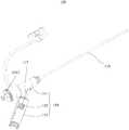
请参阅图1,一实施方式的可调弯鞘管100包括管体部分110及用于操控管体部分110的操作机构150。Referring to FIG. 1, an adjustable
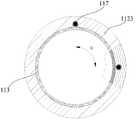
请同时参阅图2、图3及图4,管体部分110包括外管112、内管113、显影件115、滑动管116和牵引丝117。2, FIG. 3 and FIG. 4, the
外管112包括连接管1121及与连接管1121连通的管身(图未标)。连接管1121的硬度高于管身。在图示的实施方式中,连接管1121与管身同轴。The
管身包括第一管状段1123及第二管状段1125。第一管状段1123的一端与连接管1121的一端固接。第二管状段1125的一端与第一管状段1123远离连接管1121的一端固接,第一管状段1123及第二管状段1125均具有柔性。即,第一管状段1123及第二管状段1125为管身具有柔性的部分。在图示的 实施方式中,第二管状段1125、第一管状段1123和连接管1121三段硬度依次增大。在其中一个实施方式中,第二管状段1125、第一管状段1123、连接管1121为不同硬度的尼龙弹性体(PEBAX)管。进一步地,第二管状段的硬度为30D~40D。更进一步地,第二管状段1125的材料为35D PEBAX,第一管状段1123的材料为55D PEBAX、连接管1121的材料为72D PEBAX。The tubular body includes a first
第一管状段1123及第二管状段1125具有柔性,从而在第一管状段1123及第二管状段1125受到作用力时,可以发生弯曲。第一管状段1123及第二管状段1125的弯曲角度均为0°~180°,优选为90°,从而可以根据第一管状段1123及第二管状段1125的长度控制第一管状段1123及第二管状段1125的曲率半径,当然,将可调弯鞘管100应用于血管或心脏时,亦可根据实际的血管或心脏的解剖结构,设计需要的弯曲角度进而确定第一管状段1123及第二管状段1125的长度。在其中一个实施例中,第一管状段1123的长度为30毫米~70毫米,第二管状段1125的长度为20毫米~40毫米。The first
内管113收容在外管112内,且与外管112的内壁粘合。内管113与外管112同轴。内管113的内壁为光滑面,以保证其他器械顺畅运输。在图示的实施方式中,内管113的材料为聚四氟乙烯(PTFE),在其他实施方式中,内管113的材料还可以为聚对苯二甲酸乙二醇酯(PET),当然,内管113的材料不限于为PTFE或PET,其他能保证内管113的内壁光滑的材料均可。需要说明的是,内管113可以省略,只要使外管112的内壁为光滑面保证其他器械顺畅运输即可,在其他实施方式中,还可以在外管112的内表面形成内膜,内膜的材料选自PTFE及PET的至少一种。内膜可以通过涂覆等方式制备,只要保证外管112的内壁光滑即可。The
显影件115位于第二管状段1125远离第一管状段1123的一端。在图示的实施方式中,显影件115为显影环,显影件115套设并固定于内管113的外壁,并通过热熔与外管112固定。进一步地,显影件115与外管112同轴。The developing
需要说明的是,显影件115不限于为显影环,还可以通过涂覆等方式在外管112的内壁或内管113的外壁形成显影涂层,只要能起到X射线下显影 的作用即可。在其中一个实施例中,显影件115的材料选自钽及铂中的至少一种。It is to be noted that the developing
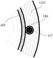
滑动管116位于内管113及外管112之间。滑动管116自第二管状段1125远离第一管状段1123的一端延伸至连接管1121远离第一管状段1123的一端。在图示的实施方式中,外管112形成有收容通道(图未标),滑动管116收容在收容通道中。在其中一个实施例中,制备时,将穿有支撑金属丝的滑动管116通过医用胶水固定在内管113的外壁,套上外管112,通过加热的方式将所有材料热熔在一起,由于滑动管116内穿设有支撑金属丝,从而热熔时滑动管116嵌入外管112,从而在外管112形成收容通道。当然,在其他实施方式中,管体部分110还包括嵌入外管112的加强管(图未示),加强管套设于内管113及滑动管116的表面。加强管为不锈钢编织网管或不锈钢弹簧管。将穿有支撑金属丝的滑动管116通过医用胶水固定在内管113的外壁后,将加强管套设于内管113及滑动管116的表面,套上外管112后通过加热的方式将所有材料热熔在一起。The sliding
滑动管116的材料为聚四氟乙烯(PTFE),当然,内管113的材料不限于为PTFE,只要能保证滑动管116的内壁光滑的材料均可。可以理解,当外管112形成光滑的收容通道时,滑动管116可以省略。The material of the sliding
请一并参阅图2至图7,牵引丝117的一端穿设于滑动管116,且固定于显影件115。在图示的实施方式中,牵引丝117为金属丝,优选地,牵引丝117的材料为镍钛合金。当然,需要说明的是,牵引丝117的材料不限于为镍钛合金,只要抗拉强度高能实现牵拉的功能即可。牵引丝117的一端通过焊接与显影件115固定。当然,当显影件115为显影涂层时,还可以在外管112内设置与外管112固接的锚定环以固定牵引丝117的一端,也可以通过粘合等方式将牵引丝117的一端直接固定至外管112。Referring to FIG. 2 to FIG. 7 , one end of the pulling
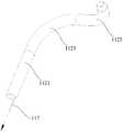
牵引丝117自第二管状段1125远离第一管状段1123的一端沿滑动管116延伸,且牵引丝117的自由端延伸出滑动管116以连接操作机构150。The pulling
在图示的实施方式中,牵引丝117自第二管状段1125远离第一管状段 1123的一端向第一管状段1123远离第二管状段1125的一端沿内管113的圆柱面呈曲线形延伸。当然,需要说明的是,牵引丝117的延伸曲线为平滑的曲线以方便对牵引丝117施加拉力使牵引丝117相对滑动管116滑动。牵引丝117自连接管1121靠近第一管状段1123的一端向远离第一管状段1123的一端直线延伸。In the illustrated embodiment, the pulling
在其中一个实施例中,外管112处于自然伸展状态即外管112为直管时,牵引丝117在第一管状段1123延伸的部分在垂直于第一管状段1123的轴线的平面的正投影为圆周角度为α的弧形。优选地,α为0°~180°,进一步为0°。In one of the embodiments, when the
在其中一个实施例中,牵引丝117在第一管状段1123呈直线型延伸。In one of the embodiments, the pulling
进一步地,外管112处于自然伸展状态即外管112为直管时,牵引丝117在第二管状段1125延伸的部分在垂直于第二管状段1125的轴线的平面的正投影为圆周角度为β的弧形。β为0°~180°,进一步优选为90°。Further, when the
请再次参阅图1,操作机构150包括连接件151、操作手柄153及操作件155。连接件151与外管112的连接管1121远离管身的一端固接。在图示的实施方式中,连接件151大致为管状,套设于连接管121且与连接管121固接。操作手柄153一端与连接件151连接,且相对连接件151倾斜设置以方便握持。操作件155设于操纵手柄153且沿远离或靠近连接件151的方向相对操作手柄153可滑动。Referring again to FIG. 1 , the
牵引丝117的自由端与操作机构150的操作件155固接,从而向远离连接件151的方向滑动操作件155可以将牵引力传递给牵引丝117。The free end of the pulling
当然,需要说明的是,通过上述操作机构150的操作件155的滑动进行操控牵引丝117仅仅是其中一种方式,还可以通过其他结构的操作机构进行控制牵引丝117,比如可以通过转动缠绕的方式收紧牵引丝117,只要能对牵引丝117施加拉力,使牵引丝117相对外管112滑动即可。Of course, it should be noted that the pulling of the pulling
上述可调弯鞘管100使用时,通过操作机构150的操作件155对牵引丝117施加拉力,牵引丝117受到拉力作用后,将作用力传递至显影件115,显影件115位于第二管状段1125远离第一管状段1123的一端,从而将牵引力 施加至第二管状段1225的末端,第二管状段1225远离第一管状段1123的一端单边受力,则会偏向受力方向产生弯曲,同时,第一管状段1123的硬度大于第二管状段1125,从而当牵引丝117传递的作用力在一定范围内时,第一管状段1223不会发生形变,当牵引丝117传递的作用力大于一定值时,第一管状段1223也会产生弯曲,由于牵引丝117沿自第二管状段1125远离第一管状段1123的一端向第一管状段1123远离第二管状段1125的一端沿内管113的圆柱面呈螺旋形曲线延伸,从而第一管状段1123靠近第二管状段1125的一端与第二管状段1125远离第一管状段1123的一段所受到的拉力的方向不同,因此第一管状段1223与第二管状段1125可以产生多段异向弯曲的效果,连接管1121因为硬度更大,则在一定拉力范围内,连接管1121不发生形变保持直形。When the adjustable
上述可调弯鞘管100的管体部分110将管身设置为具有柔性的第一管状段1223及第二管状段1225,使用时,通过牵引丝117的自由端对牵引丝117施加拉力,牵引丝117的另一端与管身固接,牵引丝117相对第一管状段1223及第二管状段1225可滑动从而对管身施加拉力,由于第一管状段1223及第二管状段1225具有柔性,会偏向受力方向产生弯曲,从而实现多段弯曲,能够更好地满足临床使用要求,适用性较强。The
可以理解,管身不限于为两段式结构,还可以为三段及三段以上的结构,只要控制管身自远离连接管1121向靠近连接管1121的方向各段管身的硬度依次增大即可。It can be understood that the pipe body is not limited to a two-stage structure, and may also be a three-stage or three-stage structure. As long as the control pipe body is increased in hardness from the connecting
请参阅图8,另一实施方式的可调弯鞘管与可调弯鞘管100的结构大致相同,其不同在于:管体部分的结构与管体部分110稍有不同,本实施方式中,管体部分的牵引丝217绕设显影件215对折形成弯折部2172,显影件215的一端的边缘抵持弯折部2172。使用时,牵引丝217的两端均为自由端,将牵引丝217的两端同时与操作机构连接即可。Referring to FIG. 8 , the structure of the adjustable curved sheath tube of the other embodiment is substantially the same as that of the adjustable
在图示的实施方式中,牵引丝217对折形成弯折部2172,当然,在其他实施方式中,牵引丝217缠绕显影件215至少一圈形成弯折部2172亦可。In the illustrated embodiment, the pulling
可以理解,在其他实施方式中,当显影件为显影涂层时,通过锚定环固定牵引丝,牵引丝217对折后形成弯折部2172,锚定环的一端的边缘抵持弯折部2172即可。It can be understood that, in other embodiments, when the developing member is a developing coating, the pulling wire is fixed by the anchoring ring, and the pulling
具有上述结构的可调弯鞘管,无需采用焊接的方式将牵引丝217固定至显影件215,从而牵引丝217的材质选择更为广泛,使用锚定环固定牵引丝时,锚定环的材质选择更多。采用上述方式固定牵引丝,牵引丝的连接方式类似柔性连接,与显影件215或锚定环的连接强度及连接稳定性更高;制备时无需焊接,也更为容易。The adjustable curved sheath tube having the above structure does not need to be welded to fix the pulling
请同时参阅图9及图10,另一实施方式的可调弯鞘管300与可调弯鞘管100的结构大致相同,其不同在于:可调弯鞘管300的管体部分310的牵引丝包括第一牵引丝3171及第二牵引丝3173,对应地,显影件为两个,分别为第一显影件314及第二显影件315,操作机构350包括第一操作件3551及第二操作件3553。Referring to FIG. 9 and FIG. 10 simultaneously, the adjustable
第一显影件314位于第一管状段3123靠近第二管状段3125的一端,第二显影件315位于第二管状段3125远离第一管状段3123的一端。The first developing
第一牵引丝3171的一端与第一显影件314固接,另一端与第一操作件3551连接。第一牵引丝3171沿平行于第一管状段3123的轴线的方向直线延伸。当然,在其他实施例中,第一牵引丝3171绕第一管状段3123的轴线呈螺旋形曲线延伸至第一管状段3123靠近连接管3121的一端。One end of the first pulling
第二牵引丝3175的一端与第二显影件315固接,另一端与第二操作件3553连接。第二牵引丝3175沿平行于第一管状段3123的轴线的方向直线延伸。当然,在其他实施例中,第一牵引丝3171绕第一管状段3123及第二管状段3125的轴线呈螺旋形曲线延伸至第一管状段3123靠近连接管3121的一端。One end of the second pulling wire 3175 is fixed to the second developing
在图示的实施方式中,第一牵引丝3171与第一管状段3123的轴线所在的平面与第二牵引丝3173与第一管状段3123的轴线所在的平面形成角度为θ的夹角。优选地,θ为0°~180°,进一步优选为90°。In the illustrated embodiment, the plane of the
请一并参阅图11~图13,上述可调弯鞘管300在使用时,通过操作机构350对第二牵引丝3173施加拉力,第二牵引丝3173受到拉力作用后,将作用力传递至第二显影件315,第二显影件315位于第二管状段3125远离第一管状段3123的一端,从而将牵引力施加至第二管状段3125的末端,第二管状段3125远离第一管状段3123的一端单边受力,则会偏向受力方向产生弯曲;通过操作机构350对第一牵引丝3171施加拉力,第一牵引丝3171受到拉力作用后,将作用力传递至第一显影件314,第一显影件314位于第一管状段3123靠近第二管状段3125的一端,从而将牵引力施加至第一管状段3123的末端,第一管状段3125的末端单边受力从而偏向受力方向产生弯曲,产生多段异向弯曲的效果。通过控制角度θ,可以控制异向弯曲的方向。Referring to FIG. 11 to FIG. 13 together, when the adjustable
需要说明的是,由于通过第一牵引丝3171及第二牵引丝3173控制第一管状段3123及第二管状段3125进行弯曲,从而第一管状段3123及第二管状段3125的硬度无特殊要求。当然,优选的,第二管状段3125、第一管状段3123、连接管3121三段硬度依次增大以方便操控。It should be noted that since the
另一实施方式的可调弯鞘管与可调弯鞘管100的结构大致相同,其不同在于:The adjustable curved sheath tube of another embodiment is substantially identical in construction to the adjustable
请参阅图14,管体部分410的第二管状段4125具有柔性,第一管状段4123具有刚性且呈弯曲状,牵引丝417能够带动第二管状段4125产生弯曲。即第二管状段4125为管身具有柔性的部分。而在自然状态下,第一管状段4123为弯曲状态。此时,为了便于牵引丝417带动第二管状段4125产生弯曲,牵引丝417与显影件415的连接点位于第二管状段4125弯曲方向的一侧。Referring to Figure 14, the
在其中一个实施例中,第一管状段4123通过塑形工艺形成弯曲状,以呈固定角度。第二管状段4125的硬度较第一管状段4123和连接管4121的硬度小。第二管状段4125采用摩擦系数较小、抗折性能和扭控性优良的高分子材料管材,例如尼龙弹性体(PEBAX)管。在其中一个实施例中,第二管状段4125的硬度为30D~40D;第一管状段4123的硬度为65D~75D;连接管4121的硬度为65D~75D。在图示的在实施例中,第二管状段4125、第一管状段 4123和连接管4121通过热熔方式连接在一起。In one of the embodiments, the
由于第二管状段4125具有柔性,从而在第二管状段4125受到作用力时,可以发生弯曲。在图示的实施例中,第二管状段4125的弯曲角度为0~180°,第一管状段的弯曲角度为25°~65°。可以理解,可以根据第一管状段4123及第二管状段4125的长度控制第一管状段4123及第二管状段4125的曲率半径,以适应不同的血管及心脏的解剖结构,或者,将管体410应用于血管或心脏时,亦可根据实际的血管或心脏的解剖结构,设计需要的弯曲角度进而确定第一管状段4123及第二管状段4125的长度。第二管状段4125弯曲后,第二管状段4125所在的平面与第一管状段4123所在的平面呈0°~360°,更进一步为70°~110°。第二管状段4125所在平面与第一管状段4123所在平面所成的夹角的角度也可以根据实际的血管或心脏的解剖结构进行调整。Since the
上述可调弯鞘管在使用时,通过操作机构对牵引丝417施加拉力,牵引丝417受到拉力作用后,将作用力传递至显影件415,显影件415位于第二管状段4125远离第一管状段4123的一端,从而将牵引力施加至第二管状段4125的末端,第二管状段4125远离第一管状段4123的一端单边受力,则会偏向受力方向产生弯曲。When the adjustable curved sheath tube is in use, a pulling force is applied to the pulling
本实施方式的可调弯鞘管的管体部分410的第一管状段4123具有刚性且呈弯曲状,第二管状段4125具有柔性,能够受力产生弯曲,对于结构差异较小的血管通路,例如,左房和右房,大部分结构及所形成的角度较为一致,本实施方式的可调弯鞘管的管体410的结构不仅能够满足临床使用,而且操作更加便捷,生产制备更加简单。The
另一实施方式的可调弯鞘管与可调弯鞘管100的结构大致相同,其不同在于:The adjustable curved sheath tube of another embodiment is substantially identical in construction to the adjustable
请参阅图15,管体部分510的第二管状段5125具有刚性且呈弯曲状,第一管状段5123具有柔性,牵引丝517能够带动第一管状段5123产生弯曲。即第一管状段5123为管身具有柔性的部分。而在自然状态下,第二管状段5125为弯曲状态。在其中一个实施例中,第二管状段5125通过塑形工艺形 成弯曲状,以呈固定角度。此时,显影件515位于第一管状段5123靠近第二管状段5125的一端。为了便于牵引丝517带动第一管状段5123产生弯曲,牵引丝517与显影件515的连接点位于第一管状段5123弯曲方向的一侧。Referring to Figure 15, the
第一管状段5123的硬度较第二管状段5125和连接管5121的硬度小。第一管状段5123、第二管状段5125和连接管5121通过热熔方式连接在一起。第一管状段5123采用摩擦系数较小、抗折性能和扭控性优良的高分子材料管材,例如尼龙弹性体(PEBAX)管。在其中一个实施例中,第一管状段5123的硬度为30D~40D;第二管状段5125的硬度为65D~75D;连接管的硬度为65D~75D。The hardness of the
由于第一管状段5123具有柔性,从而在第一管状段5123受到作用力时,可以发生弯曲。在图示的实施例中,第一管状段5123的弯曲角度为0~180°,第二管状段5125的弯曲角度为70°~110°。可以理解,可以根据第一管状段5123及第二管状段5125的长度控制第一管状段5123及第二管状段5125的曲率半径,以适应不同的血管及心脏的解剖结构,或者,将管体应用于血管或心脏时,亦可根据实际的血管或心脏的解剖结构,设计需要的弯曲角度进而确定第一管状段5123及第二管状段5125的长度。第一管状段5123弯曲后,第一管状段5123所在的平面与第二管状段5125所在的平面呈0°~360°,更进一步为70°~110°。第一管状段5123所在平面与第二管状段5125所在平面所成的夹角的角度也可以根据实际的血管或心脏的解剖结构进行调整。Since the
上述可调弯鞘管在使用时,通过操作机构对牵引丝517施加拉力,牵引丝517受到拉力作用后,将作用力传递至显影件515,显影件515位于第一管状段5123靠近第二管状段5125的一端,从而将牵引力施加至第一管状段5123靠近第二管状段5125的一端,第一管状段5123靠近第二管状段5125的一端单边受力,则会偏向受力方向产生弯曲。When the adjustable curved sheath tube is in use, a pulling force is applied to the pulling
本实施方式的可调弯鞘管的管体部分510的第一管状段5123具有柔性,能够受力产生弯曲,第二管状段5125具有刚性且呈弯曲状,对于结构差异较小的血管通路,本实施方式的可调弯鞘管的管体部分510的结构不仅能够满 足临床使用,而且操作更加便捷,生产制备更加简单。The
当然,管身不限于为两段式结构,还可以为三段及三段以上的结构,即第一管状段5123和第二管状段5125的数量也不限于各为一段,第一管状段5123和第二管状段5125的数量可以根据需要进行调整,此时对应地,牵引丝517的数量也可以根据管身具有柔性的段的数量对应增加即可。Of course, the tube body is not limited to a two-stage structure, and may also be a three-stage and three-stage structure, that is, the number of the
请参阅图16,一实施方式的医疗器械20,包括上述可调弯鞘管100和扩张穿刺装置。其中,可调弯鞘管100的结构如图1~图7所示。Referring to Figure 16, a medical device 20 of an embodiment includes the above-described adjustable
请一并参阅图17和图18,扩张穿刺装置包括扩张组件800及穿刺组件900。Referring to Figures 17 and 18 together, the expansion piercing device includes an
请同时参阅图19,扩张组件800包括扩张管810及锁合件830。在图示的实施方式中,扩张管810的一端设有接头815。接头815包括操作部8151、锁合部8153及装配部8155。操作部8151为柱形,且直径比操作部8151及装配部8155的直径大以方便握持操作。锁合部8153与操作部8151的一端连接,且与扩张管810连接。装配部8155与操作部8151的另一端连接。在图示的实施方式中,操作部8151、锁合部8153、装配部8155及扩张管810一体成型。操作部8151、锁合部8153及装配部8155开设有与扩张管810连通的通孔以供穿刺组件900的穿刺针930插入。Referring also to FIG. 19, the
锁合件830套设于锁合部8153且与锁合部8153固定连接。锁合件830能够与操作机构150固定连接。具体的,锁合件830为锁合帽,形成有内螺纹,操作机构150的连接件151远离管体部分110的一端形成有接合部1512(如图1所示)。在图示的实施方式中,接合部1512为形成于连接件151表面的外螺纹,从而能与锁合件830进行装配,当然,在其他实施方式中,也可以在锁合件830表面设置外螺纹,在连接件151上设置与之匹配的内螺纹,当然,锁合件830与连接件151也可以通过卡合等其他方式连接。The locking
穿刺组件900包括手柄910、穿刺针930、连接件950及调整件970。The piercing
请同时参阅图20,手柄910大致为筒状。手柄910开设有滑槽912及定位槽914。滑槽912自手柄910的外表面向内凹陷且沿手柄910的长度方向 延伸。定位槽914与滑槽912连通且沿手柄910的轴向延伸。在图示的实施方式中,定位槽914为多个,多个定位槽914沿手柄910的轴向排布。当然,沿手柄910轴向排布指的是大致的方向,在一些实施方式中,所有的定位槽914都位于滑槽912的一侧,在另外一些实施方式中,部分定位槽914位于滑槽912的一侧,部分定位槽914位于滑槽912的另一侧,都可以理解为沿轴向排布。Referring also to Figure 20, the
请同时参阅图21,调整件970大致为筒状。调整件970套设于手柄910,且调整件970内壁设有能与滑槽912及定位槽914配合的凸起972。在沿手柄910轴向推动调整件970时,调整件970的凸起972能沿滑槽912滑动,到其中一个定位槽914的位置转动调整件970,凸起972能滑动至定位槽914从而定位。当然在其他一些实施方式中,可以在手柄910表面设置外螺纹,在调整件970设置内螺纹,通过转动实现调整件970与手柄910的位置调整及定位。Referring also to Figure 21, the
需要说明的是,滑槽912可以为两个,凸起972也为两个,从而保证调整件970滑动的平稳。It should be noted that there may be two
手柄910的一端形成有限位部916。在图示的实施方式中,限位部916为形成于手柄910的凸台,且部分收容于滑槽912。进一步的,限位部916为楔形凸台且数量为二,沿手柄910周向对称设置。当然在其他实施方式中,限位部916还可以为凸环等结构,在一些实施方式中,限位部916还可以为与手柄910的一端螺合的螺母,从而以方便连接件950的装配,总之只要能阻止连接件950从手柄910脱落即可。One end of the
手柄910远离限位部916的一端形成有外螺纹918以方便与其他元件对接。The end of the
穿刺针930的一端插设于手柄910设有限位部916的一端。穿刺针930能够收容于扩张管810中。One end of the
请继续参阅图19,连接件950包括抵持部952及连接部954。连接部954大致为筒状,能套设于手柄910。抵持部952为凸设于连接部954的内壁的 凸环。在图示的实施方式中,抵持部952自连接部954的一端向内凸设而出,抵持部952的内径略大于手柄910外径且能被限位部916所阻挡,从而使得连接件950能在手柄910上相对滑动且不能从手柄910设置抵持部952的一端脱离。Referring to FIG. 19 , the
装配部8155形成有外螺纹,连接部954能套设于装配部8155且设有与装配部8155的外螺纹配合的内螺纹,从而通过将连接部954与装配部8155螺合从而将连接件950与接头815装配在一起。当然,在其他实施方式中,可以在装配部8155形成内螺纹,对应的在连接部954形成与之配合的外螺纹即可,还可以通过卡合等其他方式将二者固定。The
请同时继续参阅图16,使用时,将调整件970沿手柄910向靠近限位部916的定位槽914滑动并定位使调整件970抵持连接件950,将穿刺针930插入扩张管810,连接件950的连接部954套设于装配部8155,并与装配部8155螺合,此时穿刺针930收容在扩张管810内,将扩张穿刺装置组装好。将扩张管810自连接件151插入管体部分110中,锁合件830与接合部1512螺合将扩张组件800装配至管体部分110。Please refer to FIG. 16 at the same time. In use, the adjusting
以下结合附图以进行左心耳封堵手术为例,对上述医疗器械20的使用做详细说明。The use of the medical device 20 described above will be described in detail below by taking the left atrial appendage surgery as an example with reference to the accompanying drawings.
以进行左心耳封堵手术时,短款穿刺血管导丝经股静脉穿刺进入体内,接着穿刺血管鞘管沿短款穿刺血管导丝缓慢进入血管。穿刺血管鞘管进入后,撤出短款穿刺血管导丝,保留穿刺血管鞘管获取和维持器械交换和止血的入路。再沿穿刺血管鞘管进入“J”形尖端的血管导丝30,血管导丝经股静脉、下腔静脉到达右心房时,血管导丝保留在体内,撤出穿刺血管鞘管。然后在血管导丝近端,插入与扩张穿刺装置组装好的可调弯鞘管100,并进行推送,直到管体部分110的远端端头在右心房内(如图22所示),撤出血管导丝。For the left atrial appendage occlusion surgery, a short puncture vascular guide wire is inserted into the body through the femoral vein, and then the vascular sheath is inserted into the blood vessel along the short puncture vascular guide wire. After the puncture of the vascular sheath, the short puncture of the vascular guidewire is withdrawn, and the puncture of the vascular sheath is retained to maintain and maintain the instrument exchange and hemostasis. Then, along the puncture vessel sheath, the
缓慢的推动管体部分110并维持扩张穿刺装置与管体部分110位置相对固定,防止各部件位置发生相对变动,直至管体部分110的远端至合适的穿刺的卵圆窝位置上。调整调整件970的位置,使调整件970向近端滑动并定 位,轻轻推动手柄910将穿刺针930从扩张管810的远端推出来,伸出到右心房卵圆窝位置上。The
继续推送手柄910让穿刺针930的尖端穿过房间隔,进入左心房(LA)(如图23)。在保持穿刺针930在左心房内位置固定不变,将扩张组件800和管体部分110沿着穿刺针930进入左心房内。管体部分110远端整体进入后,调整调整件970的位置,使调整件970向连接件950滑动并定位,使得穿刺针930收回到扩张管810内部,然后撤出扩张穿刺装置,保留管体部分110在左心房内(如图24),建立体外到体内的通道。Pushing the
操控操作机构150(如图1~图7),使管体部分110的远端对准左心耳的入口位置。即通过操作机构150的操作件155对牵引丝117施加拉力,牵引丝117受到拉力作用后,将作用力传递至显影件115,显影件115位于第二管状段1125远离第一管状段1123的一端,从而将牵引力施加至第二弹性段1225的末端,第二弹性段1225远离第一管状段1123的一端单边受力,则会偏向受力方向产生弯曲,同时,第一管状段1123的硬度大于第二管状段1125,从而当牵引丝117传递的作用力在一定范围内时,第一管状段1223不会发生形变,当牵引丝117传递的作用力大于一定值时,第一管状段1223也会产生弯曲,由于牵引丝117沿自第二管状段1125远离第一管状段1123的一端向第一管状段1123远离第二管状段1125的一端沿内管113的圆柱面呈螺旋形曲线延伸,从而第一管状段1123靠近第二管状段1125的一端与第二管状段1125远离第一管状段1123的一段所受到的拉力的方向不同,因此第一管状段1223与第二管状段1125可以产生多段异向弯曲的效果,连接管1121因为硬度更大,则在一定拉力范围内,连接管1121不发生形变保持直形。The operating mechanism 150 (as in Figures 1-7) is manipulated such that the distal end of the
需要说明的是,上述实施例中所说的近端、远端,均是以使用时的位置确定,靠近操作者的位置为近端,远离操作者的为远端。It should be noted that the proximal end and the distal end mentioned in the above embodiments are determined by the position at the time of use, the position close to the operator is the proximal end, and the distance from the operator is the distal end.
上述医疗器械20使用时,穿刺针930同时起到穿刺和建立轨道的作用,无需中途更换管体部分110;通过调整调整件970在手柄910定位的位置,控制调整件970与限位部916之间的距离,能够精确的控制手柄910与扩张 组件800的相对运动行程,能控制穿刺针930从扩张管810中探出的长度,从而精确控制穿刺深度。When the medical device 20 is used, the
需要说明的是,上述实施例中,扩张管810均为直管,在其他实施例中,如在图25所示的实施例中,扩张组件800'的扩张管810'为弯管,扩张管810'的末端倾斜弯折延伸。由于穿刺针具有弹性,在插入扩张管810时,能跟随扩张管810进行弯折。It should be noted that, in the above embodiment, the
可以理解,上述医疗器械20的可调弯鞘管100的结构不限于为上述结构,在其他实施例中,医疗器械的可调弯鞘管还可以为具有图8~13所示的结构对应的可调弯鞘管、可调弯鞘管300、具有管体部分410的可调弯鞘管、或具有管体部分510的可调弯鞘管。It can be understood that the structure of the adjustable
上述医疗器械仅仅是可调弯鞘管的其中一种应用方式,只要需要多段异向弯曲的医疗器械均可应用上述可调弯鞘管。The above-mentioned medical device is only one of the application methods of the adjustable curved sheath tube, and the above-mentioned adjustable curved sheath tube can be applied as long as the medical instrument requiring multiple segments of the opposite bending is required.
以上所述实施例的各技术特征可以进行任意的组合,为使描述简洁,未对上述实施例中的各个技术特征所有可能的组合都进行描述,然而,只要这些技术特征的组合不存在矛盾,都应当认为是本说明书记载的范围。The technical features of the above-described embodiments may be arbitrarily combined. For the sake of brevity of description, all possible combinations of the technical features in the above embodiments are not described. However, as long as there is no contradiction between the combinations of these technical features, All should be considered as the scope of this manual.
以上所述实施例仅表达了本发明的几种实施方式,其描述较为具体和详细,但并不能因此而理解为对发明专利范围的限制。应当指出的是,对于本领域的普通技术人员来说,在不脱离本发明构思的前提下,还可以做出若干变形和改进,这些都属于本发明的保护范围。因此,本发明专利的保护范围应以所附权利要求为准。The above-described embodiments are merely illustrative of several embodiments of the present invention, and the description thereof is more specific and detailed, but is not to be construed as limiting the scope of the invention. It should be noted that a number of variations and modifications may be made by those skilled in the art without departing from the spirit and scope of the invention. Therefore, the scope of the invention should be determined by the appended claims.
Claims (21)
Translated fromChinesePriority Applications (1)
| Application Number | Priority Date | Filing Date | Title |
|---|---|---|---|
| CN201880001665.0ACN109689147B (en) | 2017-07-27 | 2018-07-17 | Adjustable Sheaths and Medical Devices |
Applications Claiming Priority (4)
| Application Number | Priority Date | Filing Date | Title |
|---|---|---|---|
| CN201710624531.1 | 2017-07-27 | ||
| CN201710624531 | 2017-07-27 | ||
| CN201711464916.2ACN109965946B (en) | 2017-12-28 | 2017-12-28 | Dilation and puncture devices, assemblies and medical devices |
| CN201711464916.2 | 2017-12-28 |
Publications (1)
| Publication Number | Publication Date |
|---|---|
| WO2019019937A1true WO2019019937A1 (en) | 2019-01-31 |
Family
ID=65040415
Family Applications (1)
| Application Number | Title | Priority Date | Filing Date |
|---|---|---|---|
| PCT/CN2018/095962CeasedWO2019019937A1 (en) | 2017-07-27 | 2018-07-17 | Adjustable curved sheath and medical instrument |
Country Status (2)
| Country | Link |
|---|---|
| CN (1) | CN109689147B (en) |
| WO (1) | WO2019019937A1 (en) |
Cited By (13)
| Publication number | Priority date | Publication date | Assignee | Title |
|---|---|---|---|---|
| CN110585560A (en)* | 2019-10-31 | 2019-12-20 | 上海加奇生物科技苏州有限公司 | Protection tube special for protecting head end shape of interventional catheter |
| CN110693628A (en)* | 2019-09-11 | 2020-01-17 | 中国医学科学院北京协和医院 | An adjustable sheath tube and inferior vena cava filter delivery device |
| CN111166994A (en)* | 2020-02-05 | 2020-05-19 | 上海汇禾医疗科技有限公司 | Sleeve assembly and instrument transportation system comprising same |
| CN112244961A (en)* | 2020-11-09 | 2021-01-22 | 北京华脉泰科医疗器械有限公司 | Sheath pipe adjusting mechanism and adjustable bent sheath pipe |
| CN112274763A (en)* | 2020-11-20 | 2021-01-29 | 康迪泰科(北京)医疗科技有限公司 | Medical catheter and method of using medical catheter |
| WO2021120917A1 (en)* | 2019-12-17 | 2021-06-24 | 先健科技(深圳)有限公司 | Delivery sheath and medical device |
| CN114681127A (en)* | 2020-12-29 | 2022-07-01 | 杭州德晋医疗科技有限公司 | Sheath pipe capable of being bent in multi-direction and transcatheter interventional system |
| CN115400322A (en)* | 2022-08-11 | 2022-11-29 | 宁波琳盛高分子材料有限公司 | Reinforced composite sheath tube |
| CN115969577A (en)* | 2022-10-09 | 2023-04-18 | 苏州汇禾医疗科技有限公司 | Delivery system and sheath for cardiovascular interventional devices |
| CN116650805A (en)* | 2023-04-24 | 2023-08-29 | 昌明生物科技(苏州)有限公司 | Bending-adjusting catheter sheath device and bending-adjusting method thereof |
| WO2023240787A1 (en)* | 2022-06-13 | 2023-12-21 | 上海普实医疗器械股份有限公司 | Bending-adjustable catheter |
| CN118806496A (en)* | 2024-09-13 | 2024-10-22 | 北京华脉泰科医疗器械股份有限公司 | Adjust the sheath |
| EP4316396A4 (en)* | 2021-03-29 | 2025-04-09 | Shenzhen Lifetech Respiration Scientific Co., Ltd. | PUNCTURE DEVICE |
Families Citing this family (10)
| Publication number | Priority date | Publication date | Assignee | Title |
|---|---|---|---|---|
| CN114642820B (en)* | 2020-12-18 | 2024-07-12 | 先健科技(深圳)有限公司 | Medical delivery catheter |
| CN112774001B (en)* | 2021-01-27 | 2024-12-13 | 康迪泰科(北京)医疗科技有限公司 | Medical catheter |
| CN114177477B (en)* | 2021-11-26 | 2024-02-13 | 上海以心医疗器械有限公司 | Bending adjusting device, bending adjusting sheath tube and medical system |
| CN114469226B (en)* | 2021-12-23 | 2024-05-17 | 杭州唯强医疗科技有限公司 | Sheath adjustable bending device and intracavitary rupture sealing system |
| CN116407729B (en)* | 2021-12-29 | 2025-06-03 | 杭州诺沁医疗器械有限公司 | Adjustable sheath tube |
| CN118105160A (en)* | 2021-12-31 | 2024-05-31 | 杭州德柯医疗科技有限公司 | A pre-shaped adaptive guide device and a transcatheter treatment system |
| CN114376769A (en)* | 2022-01-24 | 2022-04-22 | 上海臻亿医疗科技有限公司 | delivery catheter |
| CN115474888B (en)* | 2022-08-11 | 2023-04-18 | 中国人民解放军陆军军医大学第二附属医院 | Blood vessel intracavity operation catheter with visual function |
| EP4578412A1 (en)* | 2022-08-26 | 2025-07-02 | Merryspring Medical Technology (Zhejiang) Co, Ltd. | Object ablation system, control method and apparatus, medium, and electronic device |
| CN116570350A (en)* | 2023-04-04 | 2023-08-11 | 深圳佰特微医疗科技有限公司 | An adjustable curved sheath tube assembly |
Citations (7)
| Publication number | Priority date | Publication date | Assignee | Title |
|---|---|---|---|---|
| WO1992015356A1 (en)* | 1991-03-01 | 1992-09-17 | Baxter International Inc. | Cardiovascular catheter having discrete regions of varying flexibility |
| US5897537A (en)* | 1994-02-14 | 1999-04-27 | Scimed Life Systems, Inc. | Guide catheter having a plurality of filled distal grooves |
| JP2008253774A (en)* | 2008-03-31 | 2008-10-23 | Olympus Corp | Endoscope apparatus |
| CN203060553U (en)* | 2013-01-28 | 2013-07-17 | 湖南埃普特医疗器械有限公司 | Bending controllable guiding catheter |
| CN103282074A (en)* | 2010-11-03 | 2013-09-04 | 比尔卡地亚股份有限公司 | Steerable endoluminal devices and methods |
| CN103356281A (en)* | 2012-03-26 | 2013-10-23 | 韦伯斯特生物官能(以色列)有限公司 | Catheter with composite construction |
| CN103706017A (en)* | 2013-12-27 | 2014-04-09 | 先健科技(深圳)有限公司 | Sheathing tube capable of being adjusted to be bent |
Family Cites Families (7)
| Publication number | Priority date | Publication date | Assignee | Title |
|---|---|---|---|---|
| SE325986B (en)* | 1965-07-05 | 1970-07-13 | T Almen | |
| JPH01121064A (en)* | 1987-11-05 | 1989-05-12 | Terumo Corp | Catheter |
| JP4096325B2 (en)* | 1998-12-14 | 2008-06-04 | 正喜 江刺 | Active capillary and method for manufacturing the same |
| CN201410210Y (en)* | 2009-03-27 | 2010-02-24 | 王光辉 | Guide device for epidural hematoma insert tube |
| US20130274715A1 (en)* | 2012-04-13 | 2013-10-17 | Acclarent, Inc. | Method and System for Eustachian Tube Dilation |
| CN203663213U (en)* | 2013-12-27 | 2014-06-25 | 先健科技(深圳)有限公司 | Sheath capable of being bent |
| JP6010267B1 (en)* | 2015-01-21 | 2016-10-19 | オリンパス株式会社 | Endoscope insertion part and endoscope |
- 2018
- 2018-07-17WOPCT/CN2018/095962patent/WO2019019937A1/ennot_activeCeased
- 2018-07-17CNCN201880001665.0Apatent/CN109689147B/enactiveActive
Patent Citations (7)
| Publication number | Priority date | Publication date | Assignee | Title |
|---|---|---|---|---|
| WO1992015356A1 (en)* | 1991-03-01 | 1992-09-17 | Baxter International Inc. | Cardiovascular catheter having discrete regions of varying flexibility |
| US5897537A (en)* | 1994-02-14 | 1999-04-27 | Scimed Life Systems, Inc. | Guide catheter having a plurality of filled distal grooves |
| JP2008253774A (en)* | 2008-03-31 | 2008-10-23 | Olympus Corp | Endoscope apparatus |
| CN103282074A (en)* | 2010-11-03 | 2013-09-04 | 比尔卡地亚股份有限公司 | Steerable endoluminal devices and methods |
| CN103356281A (en)* | 2012-03-26 | 2013-10-23 | 韦伯斯特生物官能(以色列)有限公司 | Catheter with composite construction |
| CN203060553U (en)* | 2013-01-28 | 2013-07-17 | 湖南埃普特医疗器械有限公司 | Bending controllable guiding catheter |
| CN103706017A (en)* | 2013-12-27 | 2014-04-09 | 先健科技(深圳)有限公司 | Sheathing tube capable of being adjusted to be bent |
Cited By (17)
| Publication number | Priority date | Publication date | Assignee | Title |
|---|---|---|---|---|
| CN110693628A (en)* | 2019-09-11 | 2020-01-17 | 中国医学科学院北京协和医院 | An adjustable sheath tube and inferior vena cava filter delivery device |
| CN110693628B (en)* | 2019-09-11 | 2025-01-10 | 中国医学科学院北京协和医院 | Adjustable curved sheath tube and inferior vena cava filter delivery device |
| CN110585560A (en)* | 2019-10-31 | 2019-12-20 | 上海加奇生物科技苏州有限公司 | Protection tube special for protecting head end shape of interventional catheter |
| EP4079367A4 (en)* | 2019-12-17 | 2024-01-10 | Lifetech Scientific (Shenzhen) Co., Ltd. | Delivery sheath and medical device |
| WO2021120917A1 (en)* | 2019-12-17 | 2021-06-24 | 先健科技(深圳)有限公司 | Delivery sheath and medical device |
| CN111166994A (en)* | 2020-02-05 | 2020-05-19 | 上海汇禾医疗科技有限公司 | Sleeve assembly and instrument transportation system comprising same |
| CN112244961A (en)* | 2020-11-09 | 2021-01-22 | 北京华脉泰科医疗器械有限公司 | Sheath pipe adjusting mechanism and adjustable bent sheath pipe |
| CN112244961B (en)* | 2020-11-09 | 2024-06-07 | 北京华脉泰科医疗器械股份有限公司 | Sheath tube adjusting mechanism and adjustable bent sheath tube |
| CN112274763A (en)* | 2020-11-20 | 2021-01-29 | 康迪泰科(北京)医疗科技有限公司 | Medical catheter and method of using medical catheter |
| CN114681127A (en)* | 2020-12-29 | 2022-07-01 | 杭州德晋医疗科技有限公司 | Sheath pipe capable of being bent in multi-direction and transcatheter interventional system |
| EP4316396A4 (en)* | 2021-03-29 | 2025-04-09 | Shenzhen Lifetech Respiration Scientific Co., Ltd. | PUNCTURE DEVICE |
| WO2023240787A1 (en)* | 2022-06-13 | 2023-12-21 | 上海普实医疗器械股份有限公司 | Bending-adjustable catheter |
| CN115400322B (en)* | 2022-08-11 | 2023-11-07 | 宁波琳盛高分子材料有限公司 | Reinforced composite sheath tube |
| CN115400322A (en)* | 2022-08-11 | 2022-11-29 | 宁波琳盛高分子材料有限公司 | Reinforced composite sheath tube |
| CN115969577A (en)* | 2022-10-09 | 2023-04-18 | 苏州汇禾医疗科技有限公司 | Delivery system and sheath for cardiovascular interventional devices |
| CN116650805A (en)* | 2023-04-24 | 2023-08-29 | 昌明生物科技(苏州)有限公司 | Bending-adjusting catheter sheath device and bending-adjusting method thereof |
| CN118806496A (en)* | 2024-09-13 | 2024-10-22 | 北京华脉泰科医疗器械股份有限公司 | Adjust the sheath |
Also Published As
| Publication number | Publication date |
|---|---|
| CN109689147B (en) | 2022-05-20 |
| CN109689147A (en) | 2019-04-26 |
Similar Documents
| Publication | Publication Date | Title |
|---|---|---|
| CN109689147B (en) | Adjustable Sheaths and Medical Devices | |
| CN109965946B (en) | Dilation and puncture devices, assemblies and medical devices | |
| US12097338B2 (en) | Coaxial bi-directional catheter | |
| US20220111176A1 (en) | Introducer with steerable distal tip section | |
| US11617861B2 (en) | Triple coil catheter support | |
| US20120101442A1 (en) | Deflectable guide | |
| CN112971901B (en) | Delivery sheath and medical instrument | |
| JP2017508486A (en) | Steering tool | |
| WO2021065912A1 (en) | Medical device | |
| CN118510438A (en) | Medical devices with remote control | |
| WO2024217492A1 (en) | Outer catheter, conveying assembly and conveying system | |
| JP2023162323A (en) | Medical devices with distal control | |
| CN113116424A (en) | Transcatheter valve suture instrument and puncture needle thereof | |
| US20230028589A1 (en) | Delivery sheath and medical device | |
| CN212490011U (en) | Transcatheter valve suture instrument and puncture needle thereof | |
| CN218961553U (en) | Adjustable curved sheath pipe assembly | |
| US11701491B2 (en) | Deflectable torque cable for delivery of medical devices | |
| CN221533857U (en) | Adjustable curved sheath pipe | |
| US20240299706A1 (en) | Keyed steerable catheter devices, systems, and methods | |
| CN116570350A (en) | An adjustable curved sheath tube assembly |
Legal Events
| Date | Code | Title | Description |
|---|---|---|---|
| 121 | Ep: the epo has been informed by wipo that ep was designated in this application | Ref document number:18839121 Country of ref document:EP Kind code of ref document:A1 | |
| NENP | Non-entry into the national phase | Ref country code:DE | |
| 122 | Ep: pct application non-entry in european phase | Ref document number:18839121 Country of ref document:EP Kind code of ref document:A1 |