WO2019008618A1 - Stereoscopic optical system and imaging device provided therewith - Google Patents
Stereoscopic optical system and imaging device provided therewithDownload PDFInfo
- Publication number
- WO2019008618A1 WO2019008618A1PCT/JP2017/024301JP2017024301WWO2019008618A1WO 2019008618 A1WO2019008618 A1WO 2019008618A1JP 2017024301 WJP2017024301 WJP 2017024301WWO 2019008618 A1WO2019008618 A1WO 2019008618A1
- Authority
- WO
- WIPO (PCT)
- Prior art keywords
- optical system
- focusing
- optical
- lens group
- entrance pupil
- Prior art date
- Legal status (The legal status is an assumption and is not a legal conclusion. Google has not performed a legal analysis and makes no representation as to the accuracy of the status listed.)
- Ceased
Links
Images


Classifications
- A—HUMAN NECESSITIES
- A61—MEDICAL OR VETERINARY SCIENCE; HYGIENE
- A61B—DIAGNOSIS; SURGERY; IDENTIFICATION
- A61B1/00—Instruments for performing medical examinations of the interior of cavities or tubes of the body by visual or photographical inspection, e.g. endoscopes; Illuminating arrangements therefor
- A61B1/00163—Optical arrangements
- A61B1/00188—Optical arrangements with focusing or zooming features
- A—HUMAN NECESSITIES
- A61—MEDICAL OR VETERINARY SCIENCE; HYGIENE
- A61B—DIAGNOSIS; SURGERY; IDENTIFICATION
- A61B1/00—Instruments for performing medical examinations of the interior of cavities or tubes of the body by visual or photographical inspection, e.g. endoscopes; Illuminating arrangements therefor
- A61B1/00064—Constructional details of the endoscope body
- A61B1/00071—Insertion part of the endoscope body
- A61B1/0008—Insertion part of the endoscope body characterised by distal tip features
- A61B1/00096—Optical elements
- A—HUMAN NECESSITIES
- A61—MEDICAL OR VETERINARY SCIENCE; HYGIENE
- A61B—DIAGNOSIS; SURGERY; IDENTIFICATION
- A61B1/00—Instruments for performing medical examinations of the interior of cavities or tubes of the body by visual or photographical inspection, e.g. endoscopes; Illuminating arrangements therefor
- A61B1/00163—Optical arrangements
- A61B1/00193—Optical arrangements adapted for stereoscopic vision
- G—PHYSICS
- G02—OPTICS
- G02B—OPTICAL ELEMENTS, SYSTEMS OR APPARATUS
- G02B13/00—Optical objectives specially designed for the purposes specified below
- G—PHYSICS
- G02—OPTICS
- G02B—OPTICAL ELEMENTS, SYSTEMS OR APPARATUS
- G02B13/00—Optical objectives specially designed for the purposes specified below
- G02B13/18—Optical objectives specially designed for the purposes specified below with lenses having one or more non-spherical faces, e.g. for reducing geometrical aberration
- G—PHYSICS
- G02—OPTICS
- G02B—OPTICAL ELEMENTS, SYSTEMS OR APPARATUS
- G02B23/00—Telescopes, e.g. binoculars; Periscopes; Instruments for viewing the inside of hollow bodies; Viewfinders; Optical aiming or sighting devices
- G02B23/24—Instruments or systems for viewing the inside of hollow bodies, e.g. fibrescopes
- G02B23/2407—Optical details
- G02B23/2415—Stereoscopic endoscopes
- G—PHYSICS
- G02—OPTICS
- G02B—OPTICAL ELEMENTS, SYSTEMS OR APPARATUS
- G02B23/00—Telescopes, e.g. binoculars; Periscopes; Instruments for viewing the inside of hollow bodies; Viewfinders; Optical aiming or sighting devices
- G02B23/24—Instruments or systems for viewing the inside of hollow bodies, e.g. fibrescopes
- G02B23/2407—Optical details
- G02B23/2423—Optical details of the distal end
- G02B23/243—Objectives for endoscopes
- G—PHYSICS
- G02—OPTICS
- G02B—OPTICAL ELEMENTS, SYSTEMS OR APPARATUS
- G02B23/00—Telescopes, e.g. binoculars; Periscopes; Instruments for viewing the inside of hollow bodies; Viewfinders; Optical aiming or sighting devices
- G02B23/24—Instruments or systems for viewing the inside of hollow bodies, e.g. fibrescopes
- G02B23/26—Instruments or systems for viewing the inside of hollow bodies, e.g. fibrescopes using light guides
- G—PHYSICS
- G02—OPTICS
- G02B—OPTICAL ELEMENTS, SYSTEMS OR APPARATUS
- G02B30/00—Optical systems or apparatus for producing three-dimensional [3D] effects, e.g. stereoscopic images
- G02B30/20—Optical systems or apparatus for producing three-dimensional [3D] effects, e.g. stereoscopic images by providing first and second parallax images to an observer's left and right eyes
- G02B30/22—Optical systems or apparatus for producing three-dimensional [3D] effects, e.g. stereoscopic images by providing first and second parallax images to an observer's left and right eyes of the stereoscopic type
- H—ELECTRICITY
- H04—ELECTRIC COMMUNICATION TECHNIQUE
- H04N—PICTORIAL COMMUNICATION, e.g. TELEVISION
- H04N13/00—Stereoscopic video systems; Multi-view video systems; Details thereof
- H04N13/20—Image signal generators
- H04N13/204—Image signal generators using stereoscopic image cameras
- H04N13/239—Image signal generators using stereoscopic image cameras using two 2D image sensors having a relative position equal to or related to the interocular distance
- H—ELECTRICITY
- H04—ELECTRIC COMMUNICATION TECHNIQUE
- H04N—PICTORIAL COMMUNICATION, e.g. TELEVISION
- H04N23/00—Cameras or camera modules comprising electronic image sensors; Control thereof
- H04N23/50—Constructional details
- H04N23/55—Optical parts specially adapted for electronic image sensors; Mounting thereof
- H—ELECTRICITY
- H04—ELECTRIC COMMUNICATION TECHNIQUE
- H04N—PICTORIAL COMMUNICATION, e.g. TELEVISION
- H04N23/00—Cameras or camera modules comprising electronic image sensors; Control thereof
- H04N23/50—Constructional details
- H04N23/555—Constructional details for picking-up images in sites, inaccessible due to their dimensions or hazardous conditions, e.g. endoscopes or borescopes
- H—ELECTRICITY
- H04—ELECTRIC COMMUNICATION TECHNIQUE
- H04N—PICTORIAL COMMUNICATION, e.g. TELEVISION
- H04N23/00—Cameras or camera modules comprising electronic image sensors; Control thereof
- H04N23/95—Computational photography systems, e.g. light-field imaging systems
- H04N23/958—Computational photography systems, e.g. light-field imaging systems for extended depth of field imaging
- H04N23/959—Computational photography systems, e.g. light-field imaging systems for extended depth of field imaging by adjusting depth of field during image capture, e.g. maximising or setting range based on scene characteristics
- H—ELECTRICITY
- H04—ELECTRIC COMMUNICATION TECHNIQUE
- H04N—PICTORIAL COMMUNICATION, e.g. TELEVISION
- H04N2213/00—Details of stereoscopic systems
- H04N2213/001—Constructional or mechanical details
Definitions
- the present inventionrelates to a stereoscopic optical system and an imaging apparatus including the same, and more particularly to a stereoscopic optical system used in the field of endoscopes and an imaging apparatus including the same.
- the convergence angleis the angle between the line of sight of the right eye and the line of sight of the left eye when looking at the same object point.
- an imaging devicethat generates an image that can be viewed stereoscopically.
- acquisition of an image for the left eye and acquisition of an image for the right eyeare performed.
- Patent Document 1discloses an apparatus provided with a pair of optical systems.
- the pair of optical systemsare arranged in parallel.
- a stop having an openingis arranged in each optical system.
- the distance between two openingsthat is, the distance between two apertures corresponds to the pupil distance.
- the distance between the two aperturescan be changed.
- the change of the distance between the two apertureschanges the inward angle.
- the three-dimensional effectcan be changed.
- the object distanceWhen the object distance is short, the object is located closer to the device than when the object distance is long. For this reason, in a state in which the distance between the apertures is fixed, the inward angle becomes large and the three-dimensional effect is enhanced. The closer the object is to the imaging optical system, the stronger the three-dimensional effect, and the three-dimensional effect may be unnaturally enhanced and may be difficult to observe.
- the present inventionhas been made in view of such problems, and a small-sized optical system for stereoscopic vision in which an aberration is corrected well and an optimum inward angle can be obtained even if the object distance is short, and It aims at providing an imaging device provided.
- a first optical system and a second optical systemeach include a stop and a plurality of lens groups,
- the plurality of lens groupsincludes a lens group that moves upon at least one focusing; By moving the moving lens group, at least focusing on the near point and focusing on the far point are performed. At near point focusing, the first entrance pupil and the second entrance pupil are both located on the image side of the position at far point focusing.
- the first entrance pupilis the entrance pupil of the first optical system
- the second entrance pupilis the entrance pupil of the second optical system
- the near pointis the point in the focusing range that is located closest to the stereoscopic optical system
- the far pointis a point located in the focusing range farthest from the stereoscopic optical system, It is.
- another stereoscopic optical systemis A first optical system, a second optical system, and an optical element
- the first optical system and the second optical systemare disposed on the image side of the optical element,
- the optical elementis positioned to intersect both the optical axis of the first optical system and the optical axis of the second optical system
- Each of the first optical system and the second optical systemincludes at least two diaphragms and at least two moving lens groups that move during focusing; When these are the first moving lens group and the second moving lens group in order from the object side, By moving at least the second moving lens unit, focusing to at least the near point and focusing to the far point are performed, The first moving lens unit moves from the object side to the image side at the time of focusing from the far point to the near point, It is characterized by satisfying the following conditional expression (1).
- FLcis the focal length of the optical element
- FL1mis the focal length of the first moving lens group of the first optical system
- the near pointis the point in the focusing range that is located closest to the stereoscopic optical system
- the far pointis a point located in the focusing range farthest from the stereoscopic optical system, It is.
- another stereoscopic optical systemis A first optical system and a second optical system,
- Each of the first optical system and the second optical systemincludes a stop and a moving lens group that moves during focusing; By moving the moving lens group, at least focusing on the near point and focusing on the far point are performed.
- the moving lens unitis moved while satisfying the following conditional expression (2) to change the focusing position.
- Deis the distance between the center of the first entrance pupil and the center of the second entrance pupil
- Lobenis the distance from the position of the near point to the position of the first entrance pupil at the time of near point focusing and the light from the position of the near point to the position of the second entrance pupil at the time of near point focusing
- Axial distanceLobef is the distance from the position of the far point at the time of far point focusing to the position of the first entrance pupil, and the light from the position of the far point at far point focusing to the position of the second entrance pupil
- the first entrance pupilis the entrance pupil of the first optical system
- the second entrance pupilis the entrance pupil of the second optical system
- the near pointis the point in the focusing range that is located closest to the stereoscopic optical system
- the far pointis a point located in the focusing range farthest from the stereoscopic optical system, It is.
- another stereoscopic optical systemis A first optical system, a second optical system, and an optical element
- the first optical system and the second optical systemare disposed on the image side of the optical element
- the first optical system and the second optical systemeach include an aperture stop and a lens group having negative refractive power
- the optical elementis fixed, and the lens unit having negative refractive power moves from the object side to the image side as a moving lens unit
- An optical system for stereoscopic visioncharacterized by satisfying the following conditional expression (3).
- Daxis the distance on the optical axis between the optical axis of the first optical system and the optical axis of the second optical system
- Lnobfis the distance on the optical axis from the object side to the far point position of the lens group having negative refractive power of the first optical system at the far point focusing
- the second optical at the far point focusingThe distance on the optical axis from the most object side to the far point of the lens group having negative refractive power of the system
- Lnobnis the distance on the optical axis from the most object side surface to the near point position of the lens unit having negative refractive power of the first optical system at the time of near point focusing
- the second optical at the near point focusingThe distance on the optical axis from the most object side of the lens group having negative refractive power of the system to the position of the near point,
- the near pointis the point in the focusing range that is located
- an imaging devicemay Optical system, An imaging device having an imaging surface and converting an image formed on the imaging surface by the optical system into an electrical signal;
- the optical systemis characterized in that it is the above-mentioned optical system for stereoscopic vision.
- the present inventionit is possible to provide a compact stereoscopic optical system which can correct aberrations well and obtain an optimum inward angle even when the object distance is short, and an image pickup apparatus provided with the same.
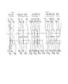
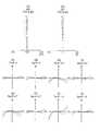
- FIG. 2is a lens cross-sectional view of the stereoscopic optical system of Example 1;
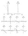
- FIG. 7is a lens cross-sectional view of the stereoscopic optical system of Example 2;
- FIG. 16is a lens cross-sectional view of the stereoscopic optical system of Example 3;
- FIG. 18is a lens cross-sectional view of the stereoscopic optical system of Example 4.
- FIG. 18is a lens cross-sectional view of the stereoscopic optical system of Example 5.
- FIG. 20is a lens cross-sectional view of the stereoscopic optical system of Example 6.
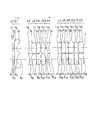
- FIG. 10is a lens cross-sectional view of the stereoscopic optical system of Modification Example 1;
- FIG. 10is a lens cross-sectional view of Modification Example 1;
- FIG. 16is a lens cross-sectional view of the stereo vision optical system of Modification 2;
- FIG. 18is a lens cross-sectional view of the stereo vision optical system of Modification 3;
- FIG. 18is a lens cross-sectional view of the stereoscopic optical system of Modification Example 4;
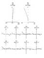
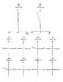
- 5is an aberration diagram of the stereoscopic optical system of Example 1.
- FIG. 5is an aberration diagram of the stereoscopic optical system of Example 1.
- FIG. 5is an aberration diagram of the stereoscopic optical system of Example 2.
- FIG. 5is an aberration diagram of the stereoscopic optical system of Example 2.
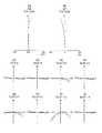
- FIG. 7is an aberration diagram of a stereoscopic optical system of Example 3.
- FIG. 7is an aberration diagram of a stereoscopic optical system of Example 3.
- FIG. 7is an aberration diagram of a stereoscopic optical system of Example 3.
- FIG. 18shows aberration diagrams of the stereoscopic optical system of Example 4.
- FIG. 18shows aberration diagrams of the stereoscopic optical system of Example 4.
- FIG. 18shows aberration diagrams of the stereoscopic optical system of Example 5.
- FIG. 18shows aberration diagrams of the stereoscopic optical system of Example 5.
- FIG. 18shows aberration diagrams of the stereoscopic optical system of Example 6.
- FIG. 18shows aberration diagrams of the stereoscopic optical system of Example 6. It is a figure showing an imaging device of this embodiment.
- optical system for stereoscopic vision of the first embodimentto the optical system for stereoscopic vision of the fourth embodiment will be described.
- common optical systeman optical system common to the optical systems for stereoscopic vision according to the four embodiments
- the common optical systemhas a first optical system and a second optical system.
- the first optical system and the second optical systemare arranged in parallel across the central axis.
- the optical axis of the first optical system and the optical axis and the central axis of the second optical systemare located on the same plane.
- Two imagesare formed by the first optical system and the second optical system.
- the first optical system and the second optical systemare arranged in parallel. Therefore, a shift occurs between the image formed by the first optical system and the image formed by the second optical system. This deviation occurs in a direction parallel to the above-described same plane and orthogonal to the central axis (hereinafter referred to as “disparity direction”). Therefore, stereoscopic vision can be performed by using these two images.
- the central axisis an axis located between the optical axis of the first optical system and the optical axis of the second optical system.
- the first optical system and the second optical systemare arranged such that the distance from the central axis to the optical axis of the first optical system and the distance from the central axis to the optical axis of the second optical system are equal. .
- the first optical system and the second optical systemare arranged in parallel.
- the first optical system and the second optical systemeach have a stop.
- the apertureis provided with an opening.
- the convergence angleis the angle between the line of sight of the right eye and the line of sight of the left eye when looking at the same object point.
- light emitted from the same object pointenters the first optical system and the second optical system.
- a ray passing through the center of the openingcorresponds to the line of sight.
- a ray passing through the center of the opening of the first optical system and a ray passing through the center of the opening of the second optical systemintersect at the same object point.
- the inward anglecorresponds to the convergence angle, where the angle at which the two lines intersect is the inward angle.
- the convergence anglechanges.
- the three-dimensional appearance(hereinafter referred to as "three-dimensional effect") changes. Therefore, the inward angle changes when the two stops move either to move away from the central axis or move close to the central axis. As a result, the three-dimensional effect can be changed.
- FIG. 1is a lens cross-sectional view of a common optical system.
- FIG. 1Ashows a lens sectional view at the time of focusing on the far point.
- FIG. 1 (b)shows a lens cross-sectional view at the time of focusing on the near point.
- the near pointis the point in the focusing range that is closest to the optical system.
- the far pointis a point in the focusing range that is located farthest from the optical system.
- the common optical systemincludes a first optical system OBJ1 and a second optical system OBJ2.
- a central axis AXCis located between the optical axis AX1 of the first optical system and the optical axis AX2 of the second optical system.
- the first optical system OBJ1 and the second optical system OBJ2are disposed symmetrically with respect to the central axis AXC.
- the optical element C1is also shown in FIG. Although this is not a component of the common optical system, it will be collectively described for convenience.
- the first optical system OBJ1 and the second optical system OBJ2are the same optical system. Therefore, the first optical system OBJ1 will be described.
- the first optical system OBJ1includes a plano-concave negative lens L1, a biconcave negative lens L2, a biconvex positive lens L3, a positive meniscus lens L4 having a convex surface facing the image side, a biconvex positive lens L5, and a biconvex lens. It has a positive lens L6, a negative meniscus lens L7 with a convex surface facing the object side, a biconvex positive lens L8, a biconcave negative lens L9, and a biconvex positive lens L10.
- the biconcave negative lens L2 and the biconvex positive lens L3are cemented.
- the biconcave negative lens L9 and the biconvex positive lens L10are cemented.
- the stop Sis disposed between the biconvex positive lens L5 and the biconvex positive lens L6.
- An optical element C1is disposed on the object side of the plano-concave negative lens L1.
- a cover glass C2is disposed on the image side of the biconvex positive lens L10.
- the optical element C1is a single parallel plate.
- the optical element C1is positioned to intersect both the optical axis of the first optical system and the optical axis of the second optical system.
- the optical element C1is not necessarily required.
- the positions of the plano-concave negative lens L1 and the negative meniscus lens L7are different at the time of focusing on the far point and the time of focusing on the near point. Also, by doing this, it is possible to make the inward angle at the far point focusing different from the inward angle at the near point focusing. As described above, in the common optical system, the movement of the lens simultaneously causes the focusing on the object located at different distances and the change of the inward angle.
- the distance between the two apertures Sdiffers between near point focusing and far point focusing.
- the method of changing the distance between the two aperturesincreases the size of the optical system.
- the distance between the two apertures Sis the same at near point focusing and at far point focusing. Therefore, in the common optical system, the enlargement of the optical system can be suppressed even if the object distance becomes short.
- movement of the lensis performed at two places. At the first position, one lens is moved at this position between the optical element C1 and the biconcave negative lens L2. At the second position, one lens is moved at this position between the biconvex positive lens L6 and the biconvex positive lens L8.
- the location to which the lens is movedis not limited to the above two locations. Further, the number of lenses to be moved is not limited to one. By moving the lens group, focusing on an object located at a different distance and changing the inward angle may be simultaneously caused.
- the focusing rangeis a range in the object space, in which the image of the object is clearly obtained when the lens in the optical system is moved along the optical axis.
- the optical system for stereoscopic visionincludes the above-described common optical system, and the first optical system and the second optical system each include a stop and a plurality of lens groups, and a plurality of lenses
- the groupincludes at least one lens group that moves at the time of focusing, and movement of the moving lens group results in at least focusing on the near point and focusing on the far point, and focusing on the near point
- the first entrance pupil and the second entrance pupilare both located on the image side of the far point focusing position.
- the first entrance pupilis the entrance pupil of the first optical system
- the second entrance pupilis the entrance pupil of the second optical system
- the near pointis the point in the focusing range that is located closest to the stereoscopic optical system
- the far pointis a point located in the focusing range farthest from the stereoscopic optical system, It is.
- the first optical systemhas at least one lens group that moves at the time of focusing. Therefore, at least focusing on the near point and focusing on the far point can be performed by the movement of the moving lens group.
- the second optical systemhas at least one lens group that moves at the time of focusing. Therefore, at least focusing on the near point and focusing on the far point can be performed by the movement of the moving lens group. The same applies to the second optical system.
- the position of the first entrance pupilchanges due to the movement of the lens group that moves during focusing.
- the position of the second entrance pupilchanges due to the movement of the lens unit that moves during focusing. With this change, the inward angle changes. Therefore, the inward angle at the far point focusing and the inward angle at the near point focusing can be made different.
- the movement of the first entrance pupilis caused by the change in the distance between the lens unit and the stop that move during focusing.
- the change in the distance between the lens unit and the stop that moves during focusingis a change in the direction along the optical axis.
- the first entrance pupil and the second entrance pupilare both located on the image side of the far point focusing position at the near point focusing.
- the inward angle at the time of focusing on the near pointcan be made an appropriate angle.
- both the inward angle at the time of focusing on the far point and the inward angle at the time of focusing on the near pointare both suppressed while the enlargement of the optical system is suppressed. It can be at an appropriate angle.
- the two images formed by the optical system for stereoscopic visionare imaged, for example, by an imaging element of an imaging device.
- an imaging devicetwo images obtained by imaging are displayed on, for example, a 3D monitor. Thereby, the image of the object can be viewed stereoscopically.
- the imaging apparatusincludes the optical system for stereoscopic vision according to the first embodiment
- the difference between the stereoscopic effect at near-point focusing and the stereoscopic effect at far-point focusingis suppressed while the enlargement of the imaging apparatus is suppressed. Can be made smaller. Therefore, according to the imaging apparatus provided with the optical system for stereoscopic vision of the first embodiment, even if stereoscopic vision is performed with an image at the time of focusing on the far point, stereoscopic vision is performed with an image at the time of focusing on the near point. , You can observe a three-dimensional image with appropriate depth.
- the optical system for stereoscopic visionincludes the above-described common optical system and an optical element, and the first optical system and the second optical system are disposed on the image side of the optical element, and are optical The element is positioned to intersect both the optical axis of the first optical system and the optical axis of the second optical system, and the first optical system and the second optical system move at the time of focusing and focusing respectively
- at least two moving lens groupsare provided, and these are sequentially taken from the object side as the first moving lens group and the second moving lens group, focusing and faring to at least the near point are achieved by the movement of at least the second moving lens group.
- Focusing to a pointis performed, and the first moving lens unit moves from the object side to the image side at the time of focusing from the far point to the near point, and satisfies the following conditional expression (1):
- FLcis the focal length of the optical element
- FL1mis the focal length of the first moving lens group of the first optical system
- the near pointis the point in the focusing range that is located closest to the stereoscopic optical system
- the far pointis a point located in the focusing range farthest from the stereoscopic optical system, It is.
- the first optical systemincludes at least a first moving lens group and a second moving lens group.
- at least the focusing to the near point and the focusing to the far pointcan be performed by the movement of at least the second moving lens group.
- the position of the first entrance pupilis changed by the movement of at least the first moving lens group.
- the position of the second entrance pupilis changed by the movement of at least the first moving lens group. With this change, the inward angle changes. Therefore, the inward angle at the far point focusing and the inward angle at the near point focusing can be made different.
- focusing on an object located at a different distance and changing the inward angleare simultaneously performed by the movement of the first moving lens group and the movement of the second moving lens group. It is happening.
- Focusing on objects located at different distancesis achieved by the movement of at least the second moving lens group.
- the first moving lens groupis moving at the time of focusing, the movement of the first moving lens group does not at all contribute to focusing on an object located at a different distance.
- the change of the inward angleis performed by the movement of at least the first movable lens group.
- the second moving lens unitis moving at the time of focusing, the movement of the second moving lens unit does not necessarily contribute to the change of the inward angle.
- the movement of the first entrance pupilis caused by the change of the distance between at least the first moving lens group and the stop.
- the change in the distance between the first moving lens unit and the stopis a change in the direction along the optical axis.
- interval of the center of two imaging devicescan be made small. Since the imaging region can be made large within the fixed outer diameter, a wide field of view can be secured.
- the first moving lens groupis positioned closer to the object than the second moving lens group.
- the first moving lens unitmoves from the object side to the image side at the time of focusing from the far point to the near point.
- the refractive power of the optical elementbecomes larger than the refractive power of the first moving lens group in the first optical system. It's too late. Therefore, the effect of moving the first entrance pupil can not be obtained sufficiently.
- the refractive power of the optical elementbecomes too large relative to the refractive power of the first moving lens group in the second optical system. Therefore, the effect of moving the second entrance pupil can not be obtained sufficiently.
- the image of the objectcan be viewed stereoscopically.
- the imaging apparatusincludes the optical system for stereoscopic vision according to the second embodiment, by satisfying the conditional expression (1), a stereoscopic image having an appropriate depth even if stereoscopic vision is performed with an image at the time of focusing on the near point. Can be observed.
- the optical system for stereoscopic vision according to the third embodimentincludes the above-described common optical system, and the first optical system and the second optical system each include a stop and a moving lens group that moves in focusing.
- the focusing of at least the near point and the focusing of the far pointare performed by the movement of the moving lens group, and the moving lens group is moved while satisfying the following conditional expression (2) to perform focusing. It is characterized by changing the position.
- Deis the distance between the center of the first entrance pupil and the center of the second entrance pupil
- Lobenis the distance from the position of the near point to the position of the first entrance pupil at the time of near point focusing and the light from the position of the near point to the position of the second entrance pupil at the time of near point focusing
- Axial distanceLobef is the distance from the position of the far point at the time of far point focusing to the position of the first entrance pupil, and the light from the position of the far point at far point focusing to the position of the second entrance pupil
- the first entrance pupilis the entrance pupil of the first optical system
- the second entrance pupilis the entrance pupil of the second optical system
- the near pointis the point in the focusing range that is located closest to the stereoscopic optical system
- the far pointis a point located in the focusing range farthest from the stereoscopic optical system, It is.
- the first optical systemincludes a moving lens group. Therefore, at least focusing on the near point and focusing on the far point can be performed by the movement of the moving lens group.
- the second optical systemincludes a moving lens group.
- the position of the first entrance pupilchanges due to the movement of the moving lens group.
- the position of the second entrance pupilchanges due to the movement of the moving lens group. With this change, the inward angle changes. Therefore, the inward angle at the far point focusing and the inward angle at the near point focusing can be made different.
- the movement of the first entrance pupilis caused by the change of the distance between the moving lens group and the stop.
- the change in the distance between the moving lens unit and the stopis a change in the direction along the optical axis.
- the image of the objectcan be viewed stereoscopically.
- the distance between the center of the first entrance pupil and the center of the second entrance pupilneeds to be a certain size or more.
- conditional expression (2)the distance between the center of the first entrance pupil and the center of the second entrance pupil can be appropriately secured. Therefore, in stereoscopic vision in an image at far point focusing, while ensuring high resolution in the depth direction, in a stereoscopic vision in an image at near focusing point, a stereoscopic image is not expanded too much in the depth direction can do. As a result, it is possible to realize a stereoscopic optical system that does not give fatigue to the observer.
- conditional expression (2)If the upper limit value of the conditional expression (2) is exceeded, the difference between the inward angle at the far point focusing and the inward angle at the near point focusing becomes too large. In this case, a stereoscopic image is excessively expanded in the depth direction in stereoscopic vision in an image at near point focusing. As a result, it is easy for the observer to be tired. Therefore, it is not preferable to exceed the upper limit value of the conditional expression (2).
- the optical system for stereoscopic vision of the fourth embodimentincludes the above-described common optical system and an optical element, and the first optical system and the second optical system are disposed on the image side of the optical element, and
- the first optical system and the second optical systemeach include a stop and a lens group having negative refractive power, and the optical element is fixed when focusing from the far point to the near point, and the negative refractive power
- the lens unit having the lens unitis moved from the object side to the image side as a moving lens unit, and the following conditional expression (3) is satisfied.
- Daxis the distance on the optical axis between the optical axis of the first optical system and the optical axis of the second optical system
- Lnobfis the distance on the optical axis from the object side to the far point position of the lens group having negative refractive power of the first optical system at the far point focusing
- the second optical at the far point focusingThe distance on the optical axis from the most object side to the far point of the lens group having negative refractive power of the system
- Lnobnis the distance on the optical axis from the most object side surface to the near point position of the lens unit having negative refractive power of the first optical system at the time of near point focusing
- the second optical at the near point focusingThe distance on the optical axis from the most object side of the lens group having negative refractive power of the system to the position of the near point,
- the near pointis the point in the focusing range that is located
- the first optical systemincludes a lens group having negative refractive power as a moving lens group. Therefore, at least focusing to the near point and focusing to the far point can be performed by the movement of the lens group having negative refractive power.
- the second optical systemincludes a lens group having negative refractive power as a moving lens group. Therefore, at least focusing to the near point and focusing to the far point can be performed by the movement of the lens group having negative refractive power. The same applies to the second optical system.
- the position of the first entrance pupilchanges due to the movement of the lens group having negative refractive power.
- the position of the second entrance pupilchanges due to the movement of the lens group having negative refractive power. With this change, the inward angle changes. Therefore, the inward angle at the far point focusing and the inward angle at the near point focusing can be made different.
- the movement of the first entrance pupilis caused by a change in the distance between the lens unit having negative refractive power and the stop.
- the change in the distance between the lens unit having negative refractive power and the stopis a change in the direction along the optical axis.
- the optical elementis fixed, and the lens group having the negative refractive power of the first optical system and the lens group having the negative refractive power of the second optical system are both on the object side. Move to the image side from
- the image of the objectcan be viewed stereoscopically.
- an image at the time of focusing on a far pointis displayed on a 3D monitor under general conditions, it is desirable that sufficient resolution in the depth direction be ensured in a stereoscopic image.
- both the lens group having negative refractive power of the first optical system and the lens group having negative refractive power of the second optical systemmove from the object side to the image side .
- the conditional expression (3)it is possible to appropriately secure the distance between the center of the first entrance pupil and the center of the second entrance pupil. Therefore, in stereoscopic vision in the image at the time of focusing on the near point, the stereoscopic image can be prevented from being excessively expanded in the depth direction. As a result, it is possible to realize a stereoscopic optical system that does not give fatigue to the observer.
- the upper limit value of the conditional expression (3)If the upper limit value of the conditional expression (3) is exceeded, the difference between the inward angle at the far point focusing and the inward angle at the near point focusing becomes too large. In this case, a stereoscopic image is excessively expanded in the depth direction in stereoscopic vision in an image at near point focusing. As a result, it is easy for the observer to be tired. Therefore, it is not preferable to exceed the upper limit value of the conditional expression (3).
- the difference between the inward angle at the far point focusing and the inward angle at the near point focusingbecomes too small.
- the moving distance of the lens unit having the negative refractive power of the first optical system and the moving distance of the lens unit having the negative refractive power of the second optical systemboth become large. Therefore, it is difficult to achieve both the downsizing of the optical system and the securing of good imaging performance. With regard to imaging performance, in particular, good correction of off-axis aberrations such as coma aberration becomes difficult.
- the stereoscopic vision optical system of the second embodimentsatisfies the following conditional expression (4).
- Lc 1 mnis the distance on the optical axis from the object side surface of the optical element at the time of near point focusing to the lens surface located closest to the object side of the first moving lens unit of the first optical system, and at the time of near point focusing
- Lc1mfis the distance on the optical axis from the object side surface of the optical element at the time of far point focusing to the lens surface located closest to the object side of the first moving lens unit of the first optical system, and at the time of far point focusing
- the first movable lens group in the first optical systemmoves from the object side to the image side at the time of focusing from the far point to the near point.
- the distance from the far point to the first entrance pupil and the distance from the near point to the first entrance pupilcan be appropriately maintained.
- the second optical systemthe same applies to the second optical system.
- the upper limit value of the conditional expression (4)If the upper limit value of the conditional expression (4) is exceeded, the amount of movement of the first moving lens group of the first optical system with respect to the optical element becomes too large. In this case, in the first optical system, the fluctuation of the aberration due to the movement of the first moving lens unit, in particular, the fluctuation amount of the off-axis aberration such as the curvature of field increases. The same applies to the second optical system. Therefore, it is not preferable to exceed the upper limit value of the conditional expression (4).
- the optical system for stereoscopic vision of the first embodiment and the optical system for stereoscopic vision of the third embodimentinclude an optical element on the object side of the first optical system and the second optical system, and satisfy the following conditional expression (5) It is preferable to do.
- Lcefis the distance on the optical axis from the object side surface of the optical element at the time of far point focusing to the position of the first entrance pupil, and from the object side of the optical element at the time of far point focusing to the position of the second entrance pupil Distance on the optical axis of the IH, maximum image height, It is.
- both the position of the first entrance pupil and the position of the second entrance pupilare too close to the image side.
- the diameter of the object side surface of the optical elementbecomes large, which makes it difficult to miniaturize the optical system. Therefore, it is not preferable to exceed the upper limit value of the conditional expression (5).
- both the position of the first entrance pupil and the position of the second entrance pupilare too close to the object side. Therefore, when the angle of view is widened, it becomes difficult to suppress distortion. If the distortion is too large, it will be difficult to obtain good resolution performance around the three-dimensional image when the image of the object is viewed stereoscopically. Further, when the image of the object is viewed stereoscopically, an appropriate stereoscopic effect can not be obtained around the stereoscopic image. Therefore, it is unpreferable to be less than the lower limit of conditional expression (5).
- the stereoscopic vision optical system of the second embodiment and the stereoscopic vision optical system of the fourth embodimentsatisfy the following conditional expression (5).
- Lcefis the distance on the optical axis from the object side surface of the optical element at the time of far point focusing to the position of the first entrance pupil, and from the object side of the optical element at the time of far point focusing to the position of the second entrance pupil Distance on the optical axis of the IH, maximum image height
- the first entrance pupilis the entrance pupil of the first optical system
- the second entrance pupilis the entrance pupil of the second optical system, It is.
- conditional expression (5)is as described above.
- both the first optical system and the second optical systemsatisfy the conditional expression (5).
- the optical system for stereoscopic vision of the first embodiment and the optical system for stereoscopic vision of the third embodimenthave an optical element on the object side of the first optical system and the second optical system, and satisfy the following conditional expression (6) It is preferable to do.
- Lcefis the distance on the optical axis from the body side of the optical element at the time of far point focusing to the position of the first entrance pupil, and the position of the second entrance pupil from the object side of the optical element at the time of far point focusing Distance on the optical axis
- Deis the distance between the center of the first entrance pupil and the center of the second entrance pupil, It is.
- both the position of the first entrance pupil and the position of the second entrance pupilare too close to the image side.
- the distance from the far point to the first entrance pupil and the distance from the far point to the second entrance pupilare shorter than the distance between the center of the first entrance pupil and the center of the second entrance pupil. Therefore, it is difficult to ensure high resolution in the depth direction in stereoscopic vision in an image at the time of focusing on a far point.
- both the position of the first entrance pupil and the position of the second entrance pupilare too close to the object side. Therefore, when the angle of view is widened, it becomes difficult to suppress distortion.
- the stereoscopic vision optical system of the second embodiment and the stereoscopic vision optical system of the fourth embodimentsatisfy the following conditional expression (6).
- Lcefis the distance on the optical axis from the body side of the optical element at the time of far point focusing to the position of the first entrance pupil, and the position of the second entrance pupil from the object side of the optical element at the time of far point focusing Distance on the optical axis
- Deis the distance between the center of the first entrance pupil and the center of the second entrance pupil
- the first entrance pupilis the entrance pupil of the first optical system
- the second entrance pupilis the entrance pupil of the second optical system, It is.
- conditional expression (6)is as described above.
- both of the first optical system and the second optical systempreferably satisfy the conditional expression (6).
- the optical system for stereoscopic vision of the first embodiment and the optical system for stereoscopic vision of the third embodimenthave an optical element on the object side of the first optical system and the second optical system, and satisfy the following conditional expression (7) It is preferable to do. 0.04 ⁇ Lcef / TTL ⁇ 0.2 (7) here, Lcef is the distance on the optical axis from the object side surface of the optical element at the time of far point focusing to the position of the first entrance pupil, and from the object side of the optical element at the time of far point focusing to the position of the second entrance pupil Distance on the optical axis of the TTL is the distance on the optical axis from the object side of the optical element to the image plane, It is.
- conditional expression (7)is the same as the technical significance of conditional expression (5).
- both the first optical system and the second optical systemsatisfy the conditional expression (7).
- the stereoscopic vision optical system of the second embodiment and the stereoscopic vision optical system of the fourth embodimentsatisfy the following conditional expression (7). 0.04 ⁇ Lcef / TTL ⁇ 0.2 (7) here, Lcef is the distance on the optical axis from the object side surface of the optical element at the time of far point focusing to the position of the first entrance pupil, and from the object side of the optical element at the time of far point focusing to the position of the second entrance pupil Distance on the optical axis of the TTL is the distance on the optical axis from the object side of the optical element to the image plane,
- the first entrance pupilis the entrance pupil of the first optical system
- the second entrance pupilis the entrance pupil of the second optical system, It is.
- conditional expression (7)is as described above.
- optical system for stereoscopic vision according to the present embodimentsatisfy the following conditional expression (8) Is preferred.
- FLfis a focal length of the first optical system at the time of far point focusing
- FLnis the focal length of the first optical system at the time of near point focusing
- the focal length of the second optical systemIt is.
- the focal length of the entire stereoscopic optical system at the time of near point focusingbecomes too long. In this case, at the time of near point focusing, it is difficult to achieve both the downsizing of the optical system and the wide field of view. Also, when focusing from the far point to the near point, the distortion aberration is likely to fluctuate greatly. When the distortion aberration is largely fluctuated, when the image of the object is viewed stereoscopically, the stereoscopic effect in the peripheral portion of the stereoscopic image largely changes. Therefore, it is not preferable to exceed the upper limit value of the conditional expression (8).
- the focal length of the entire stereoscopic optical system at the time of near point focusingbecomes too short. In this case, the diameter of the object side surface of the optical element becomes too large. Therefore, it is not preferable to fall below the lower limit value of the conditional expression (8).
- the first optical system and the second optical systemare respectively, in order from the object side, a first lens group having negative refractive power and a second lens having positive refractive power. It is preferable to include a group, a third lens group, and a fourth lens group.
- both the generation of the on-axis aberration and the generation of the off-axis aberrationcan be suppressed even if the angle of view is widened. Further, in the first optical system, it is possible to prevent the height of the light beam from increasing particularly in the optical element and the first lens group. The same applies to the second optical system.
- the optical elementpreferably has a symmetrical shape with respect to a central axis located between the optical axis of the first optical system and the optical axis of the second optical system.
- the optical system for stereoscopic vision of the present embodimentincludes an optical element on the object side of the first optical system and the second optical system, and the optical element is an optical axis of the first optical system and an optical axis of the second optical system. It is preferable that the shape is symmetrical with respect to the central axis located between them.
- the central axiscan be regarded as the optical axis of the stereoscopic optical system.
- the stereoscopic optical system of the present embodimentpreferably includes an optical element closer to the object than the first optical system and the second optical system, and the optical element is preferably fixed at the time of focusing.
- both the distance from the near point to the first entrance pupil and the distance from the far point to the first entrance pupilcan be appropriately maintained.
- the stereoscopic optical system of the present embodimentpreferably includes an optical element closer to the object than the first optical system and the second optical system, and the optical element is preferably a parallel flat plate.
- the effective ray incident on the first optical system and the effective ray incident on the second optical systemoverlap.
- the overlapping areais mainly an area near the central axis. The position of this area is decentered with respect to the optical axis of the first optical system and the optical axis of the second optical system. Therefore, decentration aberrations are likely to occur.
- the optical elementBy making the optical element a parallel plate, the occurrence of decentration aberration can be suppressed. In particular, the occurrence of decentration aberration can be suppressed at the time of near point focusing.
- the first moving lens groupis a negative lens.
- Both the first moving lens group of the first optical system and the first moving lens group of the second optical systemare preferably negative lenses. In this way, at the time of focusing from the far point to the near point, both the position of the first entrance pupil and the position of the second entrance pupil can be moved to the image side with respect to the optical element. By moving the two entrance pupils, it is possible to adjust the inward angle and to narrow the angle of view of the optical system. Since the angle of view of the optical system can be narrowed, the diameter of the optical system can be reduced.
- the third lens unitmove at the time of focusing.
- the third lens unit of the first optical system and the third lens unit of the second optical systemmove together.
- the first lens group of the first optical system and the first lens group of the second optical systemcan be moved together at the time of focusing.
- by moving the third lens unit in accordance with the movement of the first lens unitfocusing from the far point to the near point can be performed while suppressing the fluctuation of the curvature of field.
- the third lens unithas a negative refractive power, and move from the object side to the image side when focusing from the far point to the near point.
- the third lens group of the first optical system and the third lens group of the second optical systemboth have negative refractive power, and move from the object side to the image side at the time of focusing from the far point to the near point Is preferred. By doing this, the distance from the lens surface located closest to the image side of the fourth lens group to the image plane can be sufficiently secured.
- the third lens grouphas positive refractive power, and move from the image side to the object side at the time of focusing from the far point to the near point.
- Both the third lens group of the first optical system and the third lens group of the second optical systemhave refractive power, and move from the image side to the object side at the time of focusing from the far point to the near point preferable. By doing this, the entire length of the optical system can be shortened.
- the stereoscopic optical system of the present embodimentpreferably includes an optical element on the object side of the first optical system and the second optical system, and preferably satisfies the following conditional expression (9). -0.1 ⁇ IH / FLc ⁇ 0.1 (9) here, FLc is the focal length of the optical element, IH, maximum image height, It is.
- conditional expression (9)By satisfying conditional expression (9), the occurrence of decentration aberration can be suppressed. As a result, good imaging performance can be obtained.
- the optical system for stereoscopic vision of this embodimentsatisfies the following conditional expression (10). -3.0 ⁇ FL1G / IH ⁇ -1.0 (10) here, FL1G is a focal length of the first lens group of the first optical system, and a focal length of the first lens group of the second optical system, IH, maximum image height, It is.
- conditional expression (10)If the upper limit value of the conditional expression (10) is exceeded, the refractive power of the first lens group of the first optical system becomes too large. In this case, coma and distortion are generated largely. The same applies to the second optical system. Therefore, it is not preferable to exceed the upper limit value of the conditional expression (10).
- the optical system for stereoscopic vision of this embodimentsatisfies the following conditional expression (11).
- FL2Gis a focal length of the second lens group of the first optical system, and a focal length of the second lens group of the second optical system, IH, maximum image height, It is.
- the angle of the light beam emitted from the second lens group of the first optical system to the optical axisbecomes too large. Therefore, when the light emitted from the second lens group is incident on the third lens group, off-axis aberrations, in particular coma, are easily generated. The same applies to the second optical system. Therefore, it is not preferable to exceed the upper limit value of the conditional expression (11).
- the optical system for stereoscopic vision of this embodimentsatisfies the following conditional expression (12). -10.0 ⁇ FL3G / IH ⁇ 20.0 (12) here, FL3G is a focal length of the third lens group of the first optical system, and a focal length of the third lens group of the second optical system, IH, maximum image height, It is.
- Conditional expression (12)is particularly a preferable conditional expression for suppressing the fluctuation of the curvature of field.
- the optical system for stereoscopic vision of this embodimentsatisfies the following conditional expression (13).
- 132.0 ⁇ FL4G / IH ⁇ 40.0 (13) here, FL4G is a focal length of the fourth lens group of the first optical system, and a focal length of the fourth lens group of the second optical system, IH, maximum image height, It is.
- the stopbe disposed in the second lens group.
- the respective stopsare positioned approximately at the center of the optical system.
- the heights of the rays on both sides of the stopdo not differ significantly.
- the height of the light beam from the optical element to the fourth lens groupcan be suppressed in a well-balanced manner.
- the arrangement of the stop within the second lens groupis preferable for miniaturizing the optical system.
- the stopmove together with the third lens group.
- the respective stopsare positioned approximately at the center of the optical system.
- the heights of the rays on both sides of the stopdo not differ significantly.
- the height of the light beam from the optical element to the fourth lens groupcan be suppressed in a well-balanced manner.
- moving the stop together with the third lens groupis preferable in terms of downsizing.
- the first optical system and the second optical systemare preferably the same optical system.
- the vertical shiftis a shift in the direction orthogonal to the parallax direction.
- the optical system for stereoscopic vision of the present embodimentsatisfy the following conditional expression (14). 0.1 ⁇ (MG1Gf / MG1Gn) / (MG3Gf / MG3Gn) ⁇ 0.5 (14) here, MG1Gn is the lateral magnification of the first lens group of the first optical system at the time of near point focusing, and the lateral magnification of the first lens group of the second optical system, MG1Gf is a lateral magnification of the first lens group of the first optical system at the time of focusing on the far point, and a lateral magnification of the first lens group of the second optical system, MG3Gn is the lateral magnification of the third lens group of the first optical system at the time of focusing on the near point, and the lateral magnification of the third lens group of the second optical system, MG3Gf is the lateral magnification of the third lens group of the first optical system at the time of focusing on the far point, and the lateral magnification
- the first optical systemcan not obtain a sufficient multiplication effect by the movement of the first lens unit and an adjustment effect of the three-dimensional effect by the movement of the first entrance pupil. The same applies to the second optical system. Therefore, it is not preferable to fall below the lower limit value of the conditional expression (14).
- the multiplication effectis an effect of increasing the lateral magnification.
- the optical system for stereoscopic vision of this embodimentsatisfies the following conditional expression (15).
- MGnis a lateral magnification of the first optical system at the time of focusing on the near point
- MGfis the lateral magnification of the first optical system at the time of focusing on the far point
- the lateral magnification of the second optical systemIt is.
- the optical system for stereoscopic vision of this embodimentsatisfies the following conditional expression (16). 0.004 ⁇ MG1Gn / MG1Gf ⁇ 0.2 (16) here, MG1Gn is the lateral magnification of the first lens group of the first optical system at the time of near point focusing, and the lateral magnification of the first lens group of the second optical system, MG1Gf is a lateral magnification of the first lens group of the first optical system at the time of focusing on the far point, and a lateral magnification of the first lens group of the second optical system, It is.
- conditional expression (16)If the upper limit value of the conditional expression (16) is exceeded, it is necessary to secure a sufficient moving amount of the third lens unit or to increase the focusing sensitivity of the third lens unit. If the amount of movement of the third lens unit is increased, correction of off-axis aberrations, in particular, correction of curvature of field, becomes difficult. When the focusing sensitivity of the third lens unit is increased, the sensitivity of resolution deterioration due to the position error also increases. Therefore, it is not preferable to exceed the upper limit value of the conditional expression (16).
- the first optical systemwhen focusing from the far point to the near point, the first optical system obtains a sufficient multiplication effect and an adjustment effect of the three-dimensional effect by the movement of the first entrance pupil. I can not do it. The same applies to the second optical system. Accordingly, it is not preferable to fall below the lower limit value of the conditional expression (16).
- the first lens group of the first optical system and the first lens group of the second optical systembe integrated.
- the image formed by the first optical system and the second optical systemare formed.
- Vertical displacementoccurs with the image.
- the integration of the two first lens groupsmay use, for example, a method by adhesion or a method by integral molding.
- the optical system for stereoscopic vision of this embodimentsatisfies the following conditional expression (17). 0.4 ⁇ (atan (IH / FLf) / atan (IH / FLn)) / ( ⁇ f / ⁇ n) ⁇ 0.85 (17) here, ⁇ f is a half angle of view when focusing on the far point, ⁇ n is a half angle of view at near point focusing, FLf is a focal length of the first optical system at the time of far point focusing, and a focal length of the second optical system, FLn is the focal length of the first optical system at the time of near point focusing, and the focal length of the second optical system, IH, maximum image height, It is.
- Conditional expression (17)relates to the angle of view at the time of focusing on the far point and the angle of view at the time of focusing on the near point.
- the angle of view at the time of focusing on the far point and the angle of view at the time of focusing on the near pointinclude an angle of view determined from the focal length and the image height, and an actual angle of view.
- the ratio between the angle of view at the far point focusing and the angle of view at the near point focusingis obtained by comparing the angle of view determined from the focal length and the image height with the actual angle of view. There is.
- the distortioncauses a large vertical deviation between the image of the first optical system and the image of the second optical system.
- the stereoscopic imagealso becomes a stereoscopic image with vertical deviation. Therefore, it is not preferable to exceed the upper limit value of the conditional expression (17).
- the three-dimensional imagebecomes a three-dimensional image that looks like the peripheral portion pops out to the observer side. Accordingly, it is not preferable to fall below the lower limit value of the conditional expression (17).
- the image pickup apparatus of the present embodimenthas an optical system, an image pickup element having an image pickup surface and converting an image formed on the image pickup surface by the optical system into an electric signal, and the optical system is the above-described three-dimensional It is characterized in that it is a visual optical system.
- the imaging apparatus of the present embodimentit is possible to acquire an image which can obtain an appropriate three-dimensional effect when the object is stereoscopically viewed, even if the object distance is short, although it is compact. As a result, even if the object distance is short, stereoscopic vision with less fatigue can be performed.
- the lower limit value or the upper limit value of each conditional expressionmay be changed as follows. This is preferable because the effect of each conditional expression can be further ensured.
- the conditional expression (1)is as follows. It is preferable to set the lower limit value to -0.05 or -0.03. It is preferable to set the upper limit value to 0.05 or 0.03.
- the conditional expression (2)is as follows. It is preferable to set the lower limit value to 0.15 or 0.20. It is preferable to set the upper limit value to 0.60 or 0.40.
- the conditional expression (3)is as follows. It is preferable to set the lower limit value to 6.00 or 7.00. It is preferable to set the upper limit value to 20.00 or 15.00.
- the conditional expression (4)is as follows. It is preferable to set the lower limit value to 0.06 or 0.07. It is preferable to set the upper limit value to 0.20 or 0.15.
- the conditional expression (5)is as follows.
- the conditional expression (6)is as follows. It is preferable to set the lower limit value to 0.50 or 0.60. It is preferable to set the upper limit value to 1.00 or 0.95.
- the conditional expression (7)is as follows. It is preferable to set the lower limit value to 0.06 or 0.08. It is preferable to set the upper limit value to 0.17 or 0.15.
- the conditional expression (8)is as follows. It is preferable to set the lower limit value to 1.10 or 1.20. It is preferable to set the upper limit value to 1.80 or 1.70.
- the conditional expression (9)is as follows.
- the conditional expression (10)is as follows. It is preferable to set the lower limit value to ⁇ 2.40 or ⁇ 2.30. It is preferable to set the upper limit value to ⁇ 1.30 or ⁇ 1.50.
- the conditional expression (11)is as follows. It is preferable to set the lower limit value to 1.70 or 2.00. It is preferable to set the upper limit value to 5.00 or 4.50.
- the conditional expression (12)is as follows. It is preferable to set the lower limit value to -8.00 or -6.00. It is preferable to set the upper limit value to 15.00 or 10.00.
- the conditional expression (13)is as follows.
- the conditional expression (14)is as follows. It is preferable to set the lower limit value to 0.13 or 0.15. It is preferable to set the upper limit value to 0.35 or 0.28.
- the conditional expression (15)is as follows. The lower limit is preferably set to 3.50 or 4.50. It is preferable to set the upper limit value to 10.00 or 9.00.
- the conditional expression (16)is as follows. It is preferable to set the lower limit value to 0.005 or 0.006. It is preferable to set the upper limit value to 0.15 or 0.10.
- the conditional expression (17)is as follows. It is preferable to set the lower limit value to 0.50 or 0.60. It is preferable to set the upper limit value to 0.80 or 0.75.
- Lens sectional views of each embodiment and each modificationwill be described.
- the lens cross-sectional views of the embodiments and the modified examplesshow lens cross-sectional views at the time of focusing on the far point.
- the first optical system and the second optical systemare the same.
- Ashows astigmatism (AS), (b) shows distortion (DT), (c) to (j) show lateral aberration.
- FIYis image height.
- Examples 1 to 6there are an aberration diagram at the time of focusing on the near point, and an aberration diagram at the time of focusing on the far point.
- FIG. 12is an aberration diagram at the time of focusing on the near point
- FIG. 13is an aberration diagram at the time of focusing on the far point.
- the maximum value of the horizontal axisis ⁇ 20 ⁇ m.
- the vertical axisis normalized by the entrance pupil diameter.
- Tarepresents the tangential direction
- Sarepresents the sagittal direction.
- IH0is on-axis
- IH0.5is 0.5 times the maximum image height
- IH0.7is 0.7 times the maximum image height
- IH1.0is 1.0 times the maximum image height.
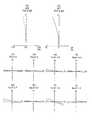
- the stereoscopic optical system of Example 1includes, in order from the object side, a plano-concave negative lens L1, a biconcave negative lens L2, a biconvex positive lens L3, and a positive meniscus lens L4 having a convex surface facing the image side. It consists of a biconvex positive lens L5, a biconvex positive lens L6, a negative meniscus lens L7 with a convex surface facing the object side, a biconvex positive lens L8, a biconcave negative lens L9, and a biconvex positive lens L10. It is done.
- the biconcave negative lens L2 and the biconvex positive lens L3are cemented.
- the biconcave negative lens L9 and the biconvex positive lens L10are cemented.
- the aperture stop Sis disposed between the biconvex positive lens L5 and the biconvex positive lens L6.
- a cover glass C1is disposed on the object side of the plano-concave negative lens L1.
- the cover glass C1is an optical element disposed closest to the object side.
- a cover glass C2is disposed on the image side of the biconvex positive lens L10.
- the plano-concave negative lens L1 of the first optical system and the plano-concave negative lens L1 of the second optical systemare integrated.
- the cover glass C1is a single parallel flat plate.
- the cover glass C1is positioned to intersect both the optical axis of the first optical system and the optical axis of the second optical system.
- both the plano-concave negative lens L1 and the negative meniscus lens L7move to the image side.
- An aspheric surfaceis provided on the image side of the plano-concave negative lens L1.
- the stereoscopic optical system of Example 2includes, in order from the object side, a plano-concave negative lens L1, a biconcave negative lens L2, a biconvex positive lens L3, and a negative meniscus lens L4 having a convex surface facing the image side.
- a positive meniscus lens L5 having a convex surface on the image sidea biconvex positive lens L6, a negative meniscus lens L7 having a convex surface on the image side, a positive meniscus lens L8 having a convex surface on the image side, and a convex surface on the object side
- the biconcave negative lens L2 and the biconvex positive lens L3are cemented.
- the negative meniscus lens L9 and the biconvex positive lens L10are cemented.
- the aperture stop Sis disposed between the biconvex positive lens L6 and the negative meniscus lens L7.
- a cover glass C1is disposed on the object side of the plano-concave negative lens L1.
- the cover glass C1is an optical element disposed closest to the object side.
- a cover glass C2is disposed on the image side of the biconvex positive lens L10.
- the plano-concave negative lens L1 of the first optical system and the plano-concave negative lens L1 of the second optical systemare integrated.
- the cover glass C1is a single parallel flat plate.
- the cover glass C1is positioned to intersect both the optical axis of the first optical system and the optical axis of the second optical system.
- the plano-concave negative lens L1moves to the image side, and the positive meniscus lens L8 moves to the object side.
- An aspheric surfaceis provided on the image side of the plano-concave negative lens L1.
- the stereoscopic optical system of Example 3includes, in order from the object side, a plano-concave negative lens L1, a biconcave negative lens L2, a biconvex positive lens L3, and a positive meniscus lens L4 having a convex surface facing the image side.
- the biconcave negative lens L2 and the biconvex positive lens L3are cemented.
- the biconvex positive lens L8 and the biconcave negative lens L9are cemented.
- the aperture stop Sis disposed between the biconvex positive lens L5 and the negative meniscus lens L6.
- a cover glass C1is disposed on the object side of the plano-concave negative lens L1.
- the cover glass C1is an optical element disposed closest to the object side.
- a cover glass C2is disposed on the image side of the positive meniscus lens L11.
- the plano-concave negative lens L1 of the first optical system and the plano-concave negative lens L1 of the second optical systemare integrated.
- the cover glass C1is a single parallel flat plate.
- the cover glass C1is positioned to intersect both the optical axis of the first optical system and the optical axis of the second optical system.
- both the plano-concave negative lens L1 and the negative meniscus lens L6move to the image side.
- the aspheric surfaceincludes the image side of the plano-concave negative lens L1, the object side of the biconcave negative lens L2, both sides of the positive meniscus lens L7, the object side of the biconvex positive lens L10, and the image side of the positive meniscus lens L11 It is provided on a total of six sides.
- the stereoscopic optical system of Example 4includes, in order from the object side, a plano-concave negative lens L1, a biconcave negative lens L2, a biconvex positive lens L3, and a positive meniscus lens L4 having a convex surface facing the image side.
- a positive meniscus lens L11having a convex surface directed to the
- the biconcave negative lens L2 and the biconvex positive lens L3are cemented.
- the biconcave negative lens L9 and the biconvex positive lens L10are cemented.
- the aperture stop Sis disposed between the biconvex positive lens L5 and the biconvex positive lens L6.
- a cover glass C1is disposed on the object side of the plano-concave negative lens L1.
- the cover glass C1is an optical element disposed closest to the object side.
- a cover glass C2is disposed on the image side of the positive meniscus lens L11.
- the plano-concave negative lens L1 of the first optical system and the plano-concave negative lens L1 of the second optical systemare integrated.
- the cover glass C1is a single parallel flat plate.
- the cover glass C1is positioned to intersect both the optical axis of the first optical system and the optical axis of the second optical system.
- both the plano-concave negative lens L1 and the negative meniscus lens L7move to the image side.
- Aspheric surfacesare provided on a total of five surfaces of the image side surface of the plano-concave negative lens L1, both surfaces of the negative meniscus lens L7, and both surfaces of the positive meniscus lens L11.
- the stereoscopic optical system of Example 5includes, in order from the object side, a plano-concave negative lens L1, a negative meniscus lens L2 having a convex surface facing the object side, a biconcave negative lens L3, and a biconvex positive lens L4.
- the biconcave negative lens L3 and the biconvex positive lens L4are cemented.
- the biconcave negative lens L10 and the biconvex positive lens L11are cemented.
- the aperture stop Sis disposed between the positive meniscus lens L6 and the biconvex positive lens L7.
- a cover glass C1is disposed on the object side of the plano-concave negative lens L1.
- the cover glass C1is an optical element disposed closest to the object side.
- a cover glass C2is disposed on the image side of the negative meniscus lens L12.
- the plano-concave negative lens L1 of the first optical system and the plano-concave negative lens L1 of the second optical systemare integrated.
- the cover glass C1is a single parallel flat plate.
- the cover glass C1is positioned to intersect both the optical axis of the first optical system and the optical axis of the second optical system.
- both the plano-concave negative lens L1 and the negative meniscus lens L8move to the image side.
- the aspheric surfaceis provided on a total of six surfaces: the image side of the plano-concave negative lens L1, the image side of the negative meniscus lens L2, both sides of the biconvex positive lens L7, and both sides of the biconvex positive lens L11. .
- the stereoscopic optical system of Example 6includes, in order from the object side, a plano-concave negative lens L1, a biconcave negative lens L2, a biconvex positive lens L3, and a positive meniscus lens L4 having a convex surface facing the image side.
- a positive meniscus lens L11having a convex surface directed to the
- the biconcave negative lens L2 and the biconvex positive lens L3are cemented.
- the biconcave negative lens L9 and the biconvex positive lens L10are cemented.
- the aperture stop Sis disposed between the biconvex positive lens L5 and the biconvex positive lens L6.
- a cover glass C1is disposed on the object side of the plano-concave negative lens L1.
- the cover glass C1is an optical element disposed closest to the object side.
- a cover glass C2is disposed on the image side of the positive meniscus lens L11.
- the plano-concave negative lens L1 of the first optical system and the plano-concave negative lens L1 of the second optical systemare integrated.
- the cover glass C1is a single parallel flat plate.
- the cover glass C1is positioned to intersect both the optical axis of the first optical system and the optical axis of the second optical system.
- both the plano-concave negative lens L1 and the negative meniscus lens L7move to the image side.
- Aspheric surfacesare provided on a total of five surfaces of the image side surface of the plano-concave negative lens L1, both surfaces of the negative meniscus lens L7, and both surfaces of the positive meniscus lens L11.
- the stereoscopic vision optical system of Modification 1is an optical system in which the cover glass of the stereoscopic vision optical system of Example 1 is replaced with another cover glass.
- both surfaces of the cover glass C1are flat.
- the object side surface of the cover glass C1is spherical and the image side surface is flat.
- the radius of curvature of the object sideis 100 mm.
- the cover glass C1is a plano-convex positive lens whose object side is a convex surface.
- the stereoscopic vision optical system of Modification 2is an optical system in which the cover glass of the stereoscopic vision optical system of Example 1 is replaced with another cover glass.
- the object side surface of the cover glass C1is a flat surface
- the image side surfaceis a spherical surface.
- the radius of curvature of the image sideis 50 mm.
- the cover glass C1is a plano-concave negative lens having a flat object side.
- the stereoscopic vision optical system of Modification 3is an optical system in which the cover glass of the stereoscopic vision optical system of Example 1 is replaced with another cover glass.
- both the object side surface and the image side surface of the cover glass C1are spherical.
- the radius of curvature on the side of the object and the radius of curvature on the image sideare both 100 mm.
- the stereoscopic vision optical system of the modification 4is an optical system in which an optical filter is disposed in the stereoscopic vision optical system of the first embodiment.
- an optical filter Fis disposed between the cover glass C1 and the plano-concave negative lens L1.
- ris a radius of curvature of each lens surface
- dis a distance between each lens surface
- ndis a refractive index of d line of each lens
- ⁇ dis Abbe's number of each lens
- *is an aspheric surface.
- the optical axis directionis z
- the direction orthogonal to the optical axisis y
- the conical coefficientis k
- the aspheric coefficientis A4, A6, A8, A10, A12,... expressed.
- z(y 2 / r) / [1 + ⁇ 1-(1 + k) (y / r) 2 ⁇ 1/2 ] + A 4 y 4 + A 6 y 6 + A 8 y 8 + A 10 y 10 + A 12 y 12 + ...
- “e ⁇ n”indicates “10 ⁇ n ”.
- Numerical embodiment 2Unit mm Surface data surface number r d nd d d Object plane ⁇ 1 0.35 0.35 1.88300 40.77 2 ⁇ ⁇ variable 3 0.5 0.54 1.88300 40.77 4 * 1.463 Variable 5-33.547 0.51 1.
- Numerical embodiment 3Unit mm Surface data surface number r d nd d Object plane ⁇ 1 0.35 0.35 1.88300 40.77 2 ⁇ ⁇ variable 3 0.4 0.49 1.88300 40.77 4 * 1.493 Variable 5 *-2.666 0.41 1.88300 40.77 6 1.955 1.09 1.67770 55.34 7-2.556 0.10 8 -7.623 0.81 1.67770 55.34 9-3.129 0.08 10 9.042 0.90 1.65160 58.55 11-3.948 0.08 12 (aperture) ⁇ ⁇ variable 13 2.502 0.41 1.77250 49.60 14 1.449 Variable 15 * 4.887 0.70 1.88300 40.77 16 * 10.269 0.13 17 6.686 0.90 1.72916 54.68 18-3.258 0.41 1.92286 18.90 19 4.438 0.13 20 * 3.937 1.13 1.88300 40.77 21 -7.381 0.10 22 -7.654 0.81 1.88300 40.77 23 *-4.593 0.12 24 1.00
- Numerical embodiment 4Unit mm Surface data surface number r d nd d Object plane ⁇ 1 0.4 0.40 1.88300 40.77 2 ⁇ ⁇ variable 3 0.6 0.67 1.88300 40.77 4 * 1.781 Variable 5-4.778 0.47 1.88300 40.77 6 2.026 1.32 1.60311 60.64 7-2.616 0.08 8-3.919 1.00 1.48749 70.24 9-3.105 0.08 10 41.122 1.09 1.74320 49.30 11 -6.197 0.08 12 (F-stop) ⁇ 0.08 13 3.648 0.88 1.74320 49.30 14 -22.644 Variable 15 * 7.023 0.50 1.88300 40.77 16 * 1.527 variable 17 6.782 1.17 1.88300 40.77 18-2.456 0.17 19 -3.688 0.48 1.92286 18.90 20 2.696 1.03 1.74320 49.30 21-4.345 0.13 22 * -6.172 0.87 1.88300 40.77 23 * -5.281 0.19 24 1.
- Numerical embodiment 5Unit mm Surface data surface number r d nd d Object plane ⁇ 1 0.35 0.35 1.88300 40.77 2 ⁇ ⁇ variable 3 0.6 0.67 1.88300 40.77 4 * 1.780 Variable 5 1.816 0.50 1.55000 53.00 6 * 1.482 2.33 7 -5.414 0.47 1.88300 40.77 8 2.013 1.32 1.60311 60.64 9-2.628 0.08 10-3.814 1.00 1.48749 70.24 11-2.990 0.08 12 -146.268 1.00 1.74320 49.30 13-4.706 0.08 14 (F-stop) ⁇ 0.08 15 3.870 0.89 1.74320 49.30 16-23.280 Variable 17 * 6.483 0.50 1.88300 40.77 18 * 1.607 Adjustable 19 6.892 1.17 1.88300 40.77 20-2.715 0.17 21-3.674 0.49 1.92286 18.90 22 2.432 0.71 1.74320 49.30 23 -3.335 0.13 24 * -3.956 0.67 1.88
- Numerical embodiment 6Unit mm Surface data surface number r d nd d d Object plane ⁇ 1 0.35 0.35 1.88300 40.77 2 ⁇ ⁇ variable 3 0.6 0.67 1.88300 40.77 4 * 1.792 Variable 5-4.783 0.47 1.88300 40.77 6 2.027 1.32 1.60311 60.64 7-2.617 0.08 8-3.923 1.00 1.48749 70.24 9-3.107 0.08 10 40.599 1.08 1.74320 49.30 11-6.276 0.08 12 (F-stop) ⁇ 0.08 13 3.630 0.88 1.74320 49.30 14 -22.682 Variable 15 * 7.034 0.50 1.88300 40.77 16 * 1.529 Adjustable 17 6.839 1.17 1.88300 40.77 18 -2.449 0.17 19-3.678 0.48 1.92286 18.90 20 2.647 1.03 1.74320 49.30 21-4.307 0.13 22 * -6.236 0.87 1.88300 40.77 23 * -5.235 0.17 24 1.
- Example 1Example 2
- Example 3(1) FL1m / FLc 0.00 0.00 0.00 (2) atan (De / Loben) -atan (De / Lobef) 0.30 0.27 0.34 (3) (Lnobf-Lnobn) / Dax 11.99 7.71 9.71 (4) (Lc1mn-Lc1mf) / TTL 0.10 0.08 0.11 (5) Lcef / IH 1.87 2.06 1.97 (6) Lcef / De 0.69 0.75 0.61 (7) Lcef / TTL 0.11 0.10 0.12 (8) FLn / FLf 1.51 1.23 1.65 (9) IH / FLc 0.00 0.00 0.00 (10) FL1G / IH -1.67 -1.76 -1.88 (11) FL2G / IH 2.30 4.37 2.53 (12) FL3G / IH-3.89 9.22-5.95 (13) FL4G / IH 3.88 15.86 3.91 (14) (10) (10) FL1G / IH -1
- FIG. 24is a diagram showing an imaging device of the present embodiment.
- the imaging device of the present embodimentis a stereoscopic endoscope.
- the stereoscopic endoscope 1includes a main body 2, a light source device 3, a camera control unit 4 (hereinafter, referred to as “CCU 4”), a scan converter 5, a monitor 6, and shutter glasses 7.
- CCU 4camera control unit 4
- the main body portion 2has an insertion portion 8 and a grip portion 9.
- the insertion portion 8is a portion to be inserted into a body cavity or the like, and is formed of a hard mantle tube.
- the outer tubehas a circular tube shape and is made of metal such as stainless steel.
- the stereoscopic endoscope 1is a rigid endoscope.
- the grasping portion 9is a portion grasped by the operator.
- the grip 9is provided with a light guide base 10. One end of the light guide cable 11 is connected to the light guide base 10. A light guide connector 12 is provided at the other end of the light guide cable 11. The light guide cable 11 is detachably connected to the grip 9 and the light source device 3.
- the light source device 3has a lamp 13 and a lens 14.
- the lamp 13generates, for example, illumination light of white light.
- the lens 14condenses the illumination light.
- the illumination light collected by the lens 14is irradiated to the end face of the light guide connector 12.
- the illumination light irradiated to the end faceis transmitted to the main body 2 by the light guide in the light guide cable 11.
- the main body 2is provided with a light guide 15.
- the light guide 15is bent in the grip portion 9 and inserted in the insertion portion 8.
- the light guide 15transmits the illumination light supplied from the light guide cable 11 to the distal end surface fixed to the distal end portion 16 of the insertion portion 8. Thereby, the illumination light is emitted forward from the tip surface.
- the optical system for stereoscopic vision of the present embodimentis disposed.
- the stereoscopic vision optical systemis configured of an objective optical system 18a and an objective optical system 18b.
- the object 17is illuminated with illumination light.
- the light from the object 17enters the objective optical system 18a and the objective optical system 18b.
- An optical imageis formed at each of the imaging position of the objective optical system 18a and the imaging position of the objective optical system 18b.
- the first imaging element 19ais disposed at the imaging position of the objective optical system 18a.
- the optical image formed by the objective optical system 18ais imaged by the first imaging element 19a.
- the second imaging element 19bis disposed at the imaging position of the objective optical system 18b.
- the optical image formed by the objective optical system 18 bis imaged by the second imaging element 19 b.
- One end of a signal cable 21is connected to the output unit 20.
- the other end of the signal cable 21is connected to the CCU 4.
- the signal output from the first imaging device 19 a and the signal output from the second imaging device 19 bare input to the CCU 4 via the signal cable 21.
- the CCU 4performs signal processing on the signals output from the first imaging device 19a and the second imaging device 19b.
- the image signal processed by the CCU 4is input to the scan converter 5.
- the scan converter 5converts the signal output from the CCU 4 into a video signal.
- the video signalis input to the monitor 6.
- the monitor 6displays the input video signal.
- the monitor 6alternately displays two images with parallax.
- the shutter glasses 7have a shutter function. By using the shutter glasses 7, an image displayed on the monitor 6 can be viewed stereoscopically.
- the present inventionis suitable for a compact stereoscopic optical system in which the aberration is well corrected and an optimum inward angle can be obtained even if the object distance is short. Further, the present invention is suitable for a compact imaging device which can obtain an appropriate three-dimensional effect when the object is viewed stereoscopically even if the object distance is short.
Landscapes
- Physics & Mathematics (AREA)
- Health & Medical Sciences (AREA)
- Life Sciences & Earth Sciences (AREA)
- Engineering & Computer Science (AREA)
- Optics & Photonics (AREA)
- Surgery (AREA)
- General Physics & Mathematics (AREA)
- Radiology & Medical Imaging (AREA)
- General Health & Medical Sciences (AREA)
- Multimedia (AREA)
- Signal Processing (AREA)
- Medical Informatics (AREA)
- Public Health (AREA)
- Pathology (AREA)
- Biophysics (AREA)
- Biomedical Technology (AREA)
- Heart & Thoracic Surgery (AREA)
- Nuclear Medicine, Radiotherapy & Molecular Imaging (AREA)
- Molecular Biology (AREA)
- Animal Behavior & Ethology (AREA)
- Veterinary Medicine (AREA)
- Astronomy & Astrophysics (AREA)
- Theoretical Computer Science (AREA)
- Computing Systems (AREA)
- Lenses (AREA)
Abstract
Description
Translated fromJapanese本発明は、立体視用光学系及びそれを備えた撮像装置に関し、主に内視鏡分野で用いられる立体視用光学系及びそれを備えた撮像装置に関する。The present invention relates to a stereoscopic optical system and an imaging apparatus including the same, and more particularly to a stereoscopic optical system used in the field of endoscopes and an imaging apparatus including the same.
同一の物点に対して瞳孔間隔が変化すると、輻輳角が変化する。輻輳角が変化すると、立体的な見え方(以下、「立体感」という)が変化する。輻輳角は、同一の物点を見た時の、右目の視線と左目の視線とのなす角度である。When the pupillary distance changes for the same object point, the convergence angle changes. When the convergence angle changes, the three-dimensional appearance (hereinafter referred to as "three-dimensional effect") changes. The convergence angle is the angle between the line of sight of the right eye and the line of sight of the left eye when looking at the same object point.
立体視が可能な画像を生成する撮像装置が知られている。この装置では、左目用の画像の取得と右目用の画像の取得が行われる。There is known an imaging device that generates an image that can be viewed stereoscopically. In this device, acquisition of an image for the left eye and acquisition of an image for the right eye are performed.
特許文献1には、一対の光学系を備えた装置が開示されている。一対の光学系は、並列に配置されている。各光学系には、開口部を有する絞りが配置されている。
一対の光学系を人間の両眼と見なすと、2つの開口部の間隔、すなわち、2つの絞りの間隔が瞳孔間隔に相当する。When a pair of optical systems are regarded as human eyes, the distance between two openings, that is, the distance between two apertures corresponds to the pupil distance.
特許文献1の装置では、同一の物点から出た光は、一対の光学系に入射する。入射した光のうち、開口部の中心を通過する光線が視線に相当する。一方の光学系の開口部の中心を通過する光線と他方の光学系の開口部の中心を通過する光線は、同一の物点の位置で交わる。この2つの交線の交わる角度を内向角とすると、内向角が輻輳角に相当する。In the device of
特許文献1の装置では、2つの絞りの間隔を変えることができる。2つの絞りの間隔が変化することで、内向角が変化する。その結果、立体感を変化させることができる。In the device of
物体距離が短い場合、物体距離が長い場合に比べて、物体は装置の近くに位置する。このため、絞りの間隔を固定した状態では、内向角が大きくなって立体感が強くなる。物体が結像光学系に近くなればなるほど立体感は強くなり、立体感が不自然に強調されて観察しにくくなることがある。When the object distance is short, the object is located closer to the device than when the object distance is long. For this reason, in a state in which the distance between the apertures is fixed, the inward angle becomes large and the three-dimensional effect is enhanced. The closer the object is to the imaging optical system, the stronger the three-dimensional effect, and the three-dimensional effect may be unnaturally enhanced and may be difficult to observe.
特許文献1の装置のように2つの絞りの間隔を変化させることによりこれを解消しようとすると、絞り間隔の変化量を非常に大きくする必要がある。その結果、結像光学系の外径が非常に大きくなって、装置が大型化してしまう。In order to solve this problem by changing the distance between the two apertures as in the device of
本発明は、このような課題に鑑みてなされたものであって、収差が良好に補正され、且つ、物体距離が短くても最適な内向角が得られる小型な立体視用光学系及びそれを備えた撮像装置を提供することを目的とする。 The present invention has been made in view of such problems, and a small-sized optical system for stereoscopic vision in which an aberration is corrected well and an optimum inward angle can be obtained even if the object distance is short, and It aims at providing an imaging device provided.
上述した課題を解決し、目的を達成するために、本発明の少なくとも幾つかの実施形態に係る立体視用光学系は、
第1光学系と、第2光学系と、を備え、
第1光学系と第2光学系は、各々、絞りと、複数のレンズ群と、を備え、
複数のレンズ群は、少なくとも1つの合焦の際に移動するレンズ群を含んでおり、
移動レンズ群の移動によって、少なくとも近点への合焦と遠点への合焦とが行われ、
近点合焦時、第1入射瞳と第2入射瞳は、共に、遠点合焦時の位置よりも像側に位置していることを特徴とする。
ここで、
第1入射瞳は、第1光学系の入射瞳、
第2入射瞳は、第2光学系の入射瞳、
近点は、合焦範囲のうち、立体視用光学系に対して最も近くに位置する点、
遠点は、合焦範囲のうち、立体視用光学系に対して最も遠くに位置する点、
である。In order to solve the problems described above and achieve the purpose, a stereoscopic optical system according to at least some embodiments of the present invention,
A first optical system and a second optical system,
The first optical system and the second optical system each include a stop and a plurality of lens groups,
The plurality of lens groups includes a lens group that moves upon at least one focusing;
By moving the moving lens group, at least focusing on the near point and focusing on the far point are performed.
At near point focusing, the first entrance pupil and the second entrance pupil are both located on the image side of the position at far point focusing.
here,
The first entrance pupil is the entrance pupil of the first optical system,
The second entrance pupil is the entrance pupil of the second optical system,
The near point is the point in the focusing range that is located closest to the stereoscopic optical system,
The far point is a point located in the focusing range farthest from the stereoscopic optical system,
It is.
また、本発明の少なくとも幾つかの実施形態に係る別の立体視用光学系は、
第1光学系と、第2光学系と、光学素子と、を備え、
第1光学系と第2光学系は、光学素子よりも像側に配置され、
光学素子は、第1光学系の光軸と第2光学系の光軸の両方と交差するように位置し、
第1光学系と第2光学系は、各々、絞りと、合焦の際に移動する移動レンズ群を少なくとも2つ備え、
これらを物体側から順に第1移動レンズ群、第2移動レンズ群とするとき、
少なくとも第2移動レンズ群の移動によって、少なくとも近点への合焦と遠点への合焦とが行われ、
第1移動レンズ群は、遠点から近点への合焦時に、物体側から像側に移動し、
以下の条件式(1)を満足することを特徴とする。
-0.1<FL1m/FLc<0.1 (1)
ここで、
FLcは、光学素子の焦点距離、
FL1mは、第1光学系の第1移動レンズ群の焦点距離、および、第2光学系の第1移動レンズ群の焦点距離、
近点は、合焦範囲のうち、立体視用光学系に対して最も近くに位置する点、
遠点は、合焦範囲のうち、立体視用光学系に対して最も遠くに位置する点、
である。In addition, another stereoscopic optical system according to at least some embodiments of the present invention is
A first optical system, a second optical system, and an optical element,
The first optical system and the second optical system are disposed on the image side of the optical element,
The optical element is positioned to intersect both the optical axis of the first optical system and the optical axis of the second optical system,
Each of the first optical system and the second optical system includes at least two diaphragms and at least two moving lens groups that move during focusing;
When these are the first moving lens group and the second moving lens group in order from the object side,
By moving at least the second moving lens unit, focusing to at least the near point and focusing to the far point are performed,
The first moving lens unit moves from the object side to the image side at the time of focusing from the far point to the near point,
It is characterized by satisfying the following conditional expression (1).
-0.1 <FL1m / FLc <0.1 (1)
here,
FLc is the focal length of the optical element,
FL1m is the focal length of the first moving lens group of the first optical system, and the focal length of the first moving lens group of the second optical system,
The near point is the point in the focusing range that is located closest to the stereoscopic optical system,
The far point is a point located in the focusing range farthest from the stereoscopic optical system,
It is.
また、本発明の少なくとも幾つかの実施形態に係る別の立体視用光学系は、
第1光学系と、第2光学系と、を備え、
第1光学系と第2光学系は、各々、絞りと、合焦の際に移動する移動レンズ群と、を備え、
移動レンズ群の移動によって、少なくとも近点への合焦と遠点への合焦とが行われ、
以下の条件式(2)を満足させながら移動レンズ群を移動させて、合焦位置を変化させることを特徴とする。
0.1<atan(De/Loben)-atan(De/Lobef)<0.8 (2)
ここで、
Deは、第1入射瞳の中心と第2入射瞳の中心との間隔、
Lobenは、近点合焦時における近点の位置から第1入射瞳の位置までの光軸上の距離、および、近点合焦時における近点の位置から第2入射瞳の位置までの光軸上の距離、
Lobefは、遠点合焦時における遠点の位置から第1入射瞳の位置までの光軸上の距離、および、遠点合焦時における遠点の位置から第2入射瞳の位置までの光軸上の距離、
第1入射瞳は、第1光学系の入射瞳、
第2入射瞳は、第2光学系の入射瞳、
近点は、合焦範囲のうち、立体視用光学系に対して最も近くに位置する点、
遠点は、合焦範囲のうち、立体視用光学系に対して最も遠くに位置する点、
である。In addition, another stereoscopic optical system according to at least some embodiments of the present invention is
A first optical system and a second optical system,
Each of the first optical system and the second optical system includes a stop and a moving lens group that moves during focusing;
By moving the moving lens group, at least focusing on the near point and focusing on the far point are performed.
The moving lens unit is moved while satisfying the following conditional expression (2) to change the focusing position.
0.1 <atan (De / Loben) -atan (De / Lobef) <0.8 (2)
here,
De is the distance between the center of the first entrance pupil and the center of the second entrance pupil,
Loben is the distance from the position of the near point to the position of the first entrance pupil at the time of near point focusing and the light from the position of the near point to the position of the second entrance pupil at the time of near point focusing Axial distance,
Lobef is the distance from the position of the far point at the time of far point focusing to the position of the first entrance pupil, and the light from the position of the far point at far point focusing to the position of the second entrance pupil Axial distance,
The first entrance pupil is the entrance pupil of the first optical system,
The second entrance pupil is the entrance pupil of the second optical system,
The near point is the point in the focusing range that is located closest to the stereoscopic optical system,
The far point is a point located in the focusing range farthest from the stereoscopic optical system,
It is.
また、本発明の少なくとも幾つかの実施形態に係る別の立体視用光学系は、
第1光学系と、第2光学系と、光学素子と、を備え、
第1光学系と第2光学系は、光学素子よりも像側に配置され、
第1光学系と第2光学系は、各々、絞りと、負の屈折力を有するレンズ群と、を備え、
遠点から近点への合焦時、光学素子は固定され、負の屈折力を有するレンズ群は移動レンズ群として物体側から像側に移動し、
以下の条件式(3)を満足することを特徴とする立体視用光学系。
5.0<(Lnobf-Lnobn)/Dax<50.0 (3)
ここで、
Daxは、第1光学系の光軸と第2光学系の光軸との光軸上の間隔、
Lnobfは、遠点合焦時における第1光学系の負の屈折力を有するレンズ群の最も物体側面から遠点の位置までの光軸上の距離、および、遠点合焦時における第2光学系の負の屈折力を有するレンズ群の最も物体側面から遠点の位置までの光軸上の距離、
Lnobnは、近点合焦時における第1光学系の負の屈折力を有するレンズ群の最も物体側面から近点の位置までの光軸上の距離、および、近点合焦時における第2光学系の負の屈折力を有するレンズ群の最も物体側面から近点の位置までの光軸上の距離、
近点は、合焦範囲のうち、立体視用光学系に対して最も近くに位置する点、
遠点は、合焦範囲のうち、立体視用光学系に対して最も遠くに位置する点、
である。In addition, another stereoscopic optical system according to at least some embodiments of the present invention is
A first optical system, a second optical system, and an optical element,
The first optical system and the second optical system are disposed on the image side of the optical element,
The first optical system and the second optical system each include an aperture stop and a lens group having negative refractive power,
During focusing from the far point to the near point, the optical element is fixed, and the lens unit having negative refractive power moves from the object side to the image side as a moving lens unit,
An optical system for stereoscopic vision characterized by satisfying the following conditional expression (3).
5.0 <(Lnobf-Lnobn) / Dax <50.0 (3)
here,
Dax is the distance on the optical axis between the optical axis of the first optical system and the optical axis of the second optical system,
Lnobf is the distance on the optical axis from the object side to the far point position of the lens group having negative refractive power of the first optical system at the far point focusing, and the second optical at the far point focusing The distance on the optical axis from the most object side to the far point of the lens group having negative refractive power of the system,
Lnobn is the distance on the optical axis from the most object side surface to the near point position of the lens unit having negative refractive power of the first optical system at the time of near point focusing, and the second optical at the near point focusing The distance on the optical axis from the most object side of the lens group having negative refractive power of the system to the position of the near point,
The near point is the point in the focusing range that is located closest to the stereoscopic optical system,
The far point is a point located in the focusing range farthest from the stereoscopic optical system,
It is.
また、本発明の少なくとも幾つかの実施形態に係る撮像装置は、
光学系と、
撮像面を持ち、且つ光学系により撮像面上に形成された像を電気信号に変換する撮像素子と、を有し、
光学系が、上述の立体視用光学系であることを特徴とする。In addition, an imaging device according to at least some embodiments of the present invention may
Optical system,
An imaging device having an imaging surface and converting an image formed on the imaging surface by the optical system into an electrical signal;
The optical system is characterized in that it is the above-mentioned optical system for stereoscopic vision.
本発明によれば、収差が良好に補正され、且つ、物体距離が短くても最適な内向角が得られる小型な立体視用光学系及びそれを備えた撮像装置を提供することができる。According to the present invention, it is possible to provide a compact stereoscopic optical system which can correct aberrations well and obtain an optimum inward angle even when the object distance is short, and an image pickup apparatus provided with the same.
実施例の説明に先立ち、本発明のある態様にかかる実施形態の作用効果を説明する。なお、本実施形態の作用効果を具体的に説明するに際しては、具体的な例を示して説明することになる。しかし、後述する実施例の場合と同様に、それらの例示される態様はあくまでも本発明に含まれる態様のうちの一部に過ぎず、その態様には数多くのバリエーションが存在する。したがって、本発明は例示される態様に限定されるものではない。Prior to the description of the examples, the operation and effects of the embodiment according to an aspect of the present invention will be described. In addition, when demonstrating the effect of this embodiment concretely, a specific example is shown and demonstrated. However, as in the case of the examples described later, those exemplified aspects are only some of the aspects included in the present invention, and there are many variations in the aspects. Accordingly, the present invention is not limited to the illustrated embodiments.
以下、第1実施形態の立体視用光学系乃至第4実施形態の立体視用光学系について説明する。この説明に先立って、4つの実施形態の立体視用光学系で共通する光学系(以下、「共通の光学系」という)について説明する。Hereinafter, the optical system for stereoscopic vision of the first embodiment to the optical system for stereoscopic vision of the fourth embodiment will be described. Prior to this explanation, an optical system common to the optical systems for stereoscopic vision according to the four embodiments (hereinafter, referred to as “common optical system”) will be described.
共通の光学系は、第1光学系と第2光学系を有する。第1光学系と第2光学系は、中心軸を挟んで並列に配置されている。第1光学系の光軸、第2光学系の光軸及び中心軸は、同一平面上に位置している。The common optical system has a first optical system and a second optical system. The first optical system and the second optical system are arranged in parallel across the central axis. The optical axis of the first optical system and the optical axis and the central axis of the second optical system are located on the same plane.
第1光学系と第2光学系によって、2つの像が形成される。上述のように、第1光学系と第2光学系は並列に配置されている。そのため、第1光学系で形成された像と第2光学系で形成された像との間には、ずれが生じている。このずれは、上述の同一平面と平行で、且つ、中心軸と直交する方向(以下、「視差方向」という)に生じる。よって、この2つの像を用いることで、立体視を行うことができる。Two images are formed by the first optical system and the second optical system. As described above, the first optical system and the second optical system are arranged in parallel. Therefore, a shift occurs between the image formed by the first optical system and the image formed by the second optical system. This deviation occurs in a direction parallel to the above-described same plane and orthogonal to the central axis (hereinafter referred to as “disparity direction”). Therefore, stereoscopic vision can be performed by using these two images.
中心軸は、第1光学系の光軸と第2光学系の光軸との間に位置する軸である。第1光学系と第2光学系は、中心軸から第1光学系の光軸までの距離と、中心軸から第2光学系の光軸までの距離と、が等しくなるように配置されている。The central axis is an axis located between the optical axis of the first optical system and the optical axis of the second optical system. The first optical system and the second optical system are arranged such that the distance from the central axis to the optical axis of the first optical system and the distance from the central axis to the optical axis of the second optical system are equal. .
上述のように、共通の光学系では、第1光学系と第2光学系は、並列に配置されている。また、第1光学系と第2光学系は、各々、絞りを有する。絞りには、開口部が設けられている。第1光学系と第2光学系を人間の両眼と見なすと、2つの開口部の間隔、すなわち、2つの絞りの間隔は瞳孔間隔に相当する。As described above, in the common optical system, the first optical system and the second optical system are arranged in parallel. The first optical system and the second optical system each have a stop. The aperture is provided with an opening. When the first optical system and the second optical system are regarded as human eyes, the distance between the two openings, that is, the distance between the two apertures corresponds to the pupil distance.
輻輳角は、同一の物点を見た時の、右目の視線と左目の視線とのなす角度である。共通の光学系では、同一の物点から出た光は、第1光学系と第2光学系に入射する。入射した光のうち、開口部の中心を通過する光線が視線に相当する。第1光学系の開口部の中心を通過する光線と第2光学系の開口部の中心を通過する光線は、同一の物点の位置で交わる。この2つの交線の交わる角度を内向角とすると、内向角が輻輳角に相当する。The convergence angle is the angle between the line of sight of the right eye and the line of sight of the left eye when looking at the same object point. In the common optical system, light emitted from the same object point enters the first optical system and the second optical system. Of the incident light, a ray passing through the center of the opening corresponds to the line of sight. A ray passing through the center of the opening of the first optical system and a ray passing through the center of the opening of the second optical system intersect at the same object point. The inward angle corresponds to the convergence angle, where the angle at which the two lines intersect is the inward angle.
同一の物点に対して瞳孔間隔が変化すると、輻輳角が変化する。輻輳角が変化すると、立体的な見え方(以下、「立体感」という)が変化する。よって、2つの絞りが、共に中心軸から離れるように移動するか、又は、共に中心軸に近づくように移動することで内向角が変化する。その結果、立体感を変化させることができる。When the pupillary distance changes for the same object point, the convergence angle changes. When the convergence angle changes, the three-dimensional appearance (hereinafter referred to as "three-dimensional effect") changes. Therefore, the inward angle changes when the two stops move either to move away from the central axis or move close to the central axis. As a result, the three-dimensional effect can be changed.
共通の光学系の具体的な構成を示す。図1は、共通の光学系のレンズ断面図である。図1(a)は、遠点合焦時のレンズ断面図を示している。図1(b)は、近点合焦時のレンズ断面図を示している。近点は、合焦範囲のうち、光学系に対して最も近くに位置する点である。遠点は、合焦範囲のうち、光学系に対して最も遠くに位置する点である。The concrete composition of a common optical system is shown. FIG. 1 is a lens cross-sectional view of a common optical system. FIG. 1A shows a lens sectional view at the time of focusing on the far point. FIG. 1 (b) shows a lens cross-sectional view at the time of focusing on the near point. The near point is the point in the focusing range that is closest to the optical system. The far point is a point in the focusing range that is located farthest from the optical system.
共通の光学系は、第1光学系OBJ1と、第2光学系OBJ2と、を備えている。第1光学系の光軸AX1と第2光学系の光軸AX2との間に、中心軸AXCが位置している。第1光学系OBJ1と第2光学系OBJ2は、中心軸AXCを挟んで対称に配置されている。なお、図1には光学素子C1も示されている。これは共通光学系の構成要素ではないが、便宜上まとめて説明する。The common optical system includes a first optical system OBJ1 and a second optical system OBJ2. A central axis AXC is located between the optical axis AX1 of the first optical system and the optical axis AX2 of the second optical system. The first optical system OBJ1 and the second optical system OBJ2 are disposed symmetrically with respect to the central axis AXC. The optical element C1 is also shown in FIG. Although this is not a component of the common optical system, it will be collectively described for convenience.
図1(a)、(b)に示す共通の光学系では、第1光学系OBJ1と第2光学系OBJ2は、同一の光学系になっている。よって、第1光学系OBJ1について説明する。In the common optical system shown in FIGS. 1A and 1B, the first optical system OBJ1 and the second optical system OBJ2 are the same optical system. Therefore, the first optical system OBJ1 will be described.
第1光学系OBJ1は、平凹負レンズL1と、両凹負レンズL2と、両凸正レンズL3と、像側に凸面を向けた正メニスカスレンズL4と、両凸正レンズL5と、両凸正レンズL6と、物体側に凸面を向けた負メニスカスレンズL7と、両凸正レンズL8と、両凹負レンズL9と、両凸正レンズL10と、を有する。The first optical system OBJ1 includes a plano-concave negative lens L1, a biconcave negative lens L2, a biconvex positive lens L3, a positive meniscus lens L4 having a convex surface facing the image side, a biconvex positive lens L5, and a biconvex lens. It has a positive lens L6, a negative meniscus lens L7 with a convex surface facing the object side, a biconvex positive lens L8, a biconcave negative lens L9, and a biconvex positive lens L10.
両凹負レンズL2と両凸正レンズL3とが接合されている。両凹負レンズL9と両凸正レンズL10とが接合されている。The biconcave negative lens L2 and the biconvex positive lens L3 are cemented. The biconcave negative lens L9 and the biconvex positive lens L10 are cemented.
絞りSは、両凸正レンズL5と両凸正レンズL6との間に配置されている。平凹負レンズL1の物体側に、光学素子C1が配置されている。両凸正レンズL10の像側に、カバーガラスC2が配置されている。The stop S is disposed between the biconvex positive lens L5 and the biconvex positive lens L6. An optical element C1 is disposed on the object side of the plano-concave negative lens L1. A cover glass C2 is disposed on the image side of the biconvex positive lens L10.
光学素子C1は、1枚の平行平板である。光学素子C1は、第1光学系の光軸と第2光学系の光軸の両方と交差するように位置している。光学素子C1は、必ずしも必要ではない。The optical element C1 is a single parallel plate. The optical element C1 is positioned to intersect both the optical axis of the first optical system and the optical axis of the second optical system. The optical element C1 is not necessarily required.
共通の光学系では、遠点合焦時と近点合焦時とで、平凹負レンズL1と負メニスカスレンズL7の位置が異なる。また、このようにすることで、遠点合焦時の内向角と近点合焦時の内向角とを異ならせることができる。このように、共通の光学系では、レンズの移動によって、異なる距離に位置する物体への合焦と、内向角の変更と、が同時に生じている。In the common optical system, the positions of the plano-concave negative lens L1 and the negative meniscus lens L7 are different at the time of focusing on the far point and the time of focusing on the near point. Also, by doing this, it is possible to make the inward angle at the far point focusing different from the inward angle at the near point focusing. As described above, in the common optical system, the movement of the lens simultaneously causes the focusing on the object located at different distances and the change of the inward angle.
上述のように、2つの絞りの間隔を変える方法では、2つの絞りSの間隔は、近点合焦時と遠点合焦時とで異なる。また、物体距離が短くなるにつれて、2つの絞りの間隔を狭くする必要がある。そのため、2つの絞りの間隔を変える方法では、光学系が大型化する。As described above, in the method of changing the distance between the two apertures, the distance between the two apertures S differs between near point focusing and far point focusing. In addition, as the object distance decreases, it is necessary to narrow the distance between the two apertures. Therefore, the method of changing the distance between the two apertures increases the size of the optical system.
これに対して、図1(a)、(b)に示す共通の光学系では、2つの絞りSの間隔は、近点合焦時と遠点合焦時とで同じである。そのため、共通の光学系では、物体距離が短くなっても、光学系の大型化を抑制することができる。On the other hand, in the common optical system shown in FIGS. 1A and 1B, the distance between the two apertures S is the same at near point focusing and at far point focusing. Therefore, in the common optical system, the enlargement of the optical system can be suppressed even if the object distance becomes short.
図1(a)、(b)に示す共通の光学系では、2箇所でレンズの移動が行われている。1箇所目は、光学素子C1と両凹負レンズL2との間で、この箇所では1つのレンズが移動している。2箇所目は、両凸正レンズL6と両凸正レンズL8との間で、この箇所では、1つのレンズが移動している。In the common optical system shown in FIGS. 1A and 1B, movement of the lens is performed at two places. At the first position, one lens is moved at this position between the optical element C1 and the biconcave negative lens L2. At the second position, one lens is moved at this position between the biconvex positive lens L6 and the biconvex positive lens L8.
しかしながら、レンズを移動させる箇所は、上記の2箇所に限られない。また、移動させるレンズの数は1つに限られない。レンズ群を移動させることで、異なる距離に位置する物体への合焦と、内向角の変更と、が同時に生じるようにしても良い。However, the location to which the lens is moved is not limited to the above two locations. Further, the number of lenses to be moved is not limited to one. By moving the lens group, focusing on an object located at a different distance and changing the inward angle may be simultaneously caused.
合焦範囲は、物体空間における範囲であって、光学系内のレンズを光軸に沿って移動させたときに、物体の像が鮮明に得られる範囲である。The focusing range is a range in the object space, in which the image of the object is clearly obtained when the lens in the optical system is moved along the optical axis.
第1実施形態の立体視用光学系は、上述の共通の光学系を備えると共に、第1光学系と第2光学系は、各々、絞りと、複数のレンズ群と、を備え、複数のレンズ群は、少なくとも1つの合焦の際に移動するレンズ群を含んでおり、移動レンズ群の移動によって、少なくとも近点への合焦と遠点への合焦とが行われ、近点合焦時、第1入射瞳と第2入射瞳は、共に、遠点合焦時の位置よりも像側に位置していることを特徴とする。
ここで、
第1入射瞳は、第1光学系の入射瞳、
第2入射瞳は、第2光学系の入射瞳、
近点は、合焦範囲のうち、立体視用光学系に対して最も近くに位置する点、
遠点は、合焦範囲のうち、立体視用光学系に対して最も遠くに位置する点、
である。The optical system for stereoscopic vision according to the first embodiment includes the above-described common optical system, and the first optical system and the second optical system each include a stop and a plurality of lens groups, and a plurality of lenses The group includes at least one lens group that moves at the time of focusing, and movement of the moving lens group results in at least focusing on the near point and focusing on the far point, and focusing on the near point The first entrance pupil and the second entrance pupil are both located on the image side of the far point focusing position.
here,
The first entrance pupil is the entrance pupil of the first optical system,
The second entrance pupil is the entrance pupil of the second optical system,
The near point is the point in the focusing range that is located closest to the stereoscopic optical system,
The far point is a point located in the focusing range farthest from the stereoscopic optical system,
It is.
第1実施形態の立体視用光学系では、第1光学系は、合焦の際に移動するレンズ群を少なくとも1つ有する。そのため、移動レンズ群の移動によって、少なくとも近点への合焦と遠点への合焦とを、行うことができる。第2光学系についても、同様である。In the optical system for stereoscopic vision of the first embodiment, the first optical system has at least one lens group that moves at the time of focusing. Therefore, at least focusing on the near point and focusing on the far point can be performed by the movement of the moving lens group. The same applies to the second optical system.
第1光学系では、合焦の際に移動するレンズ群の移動によって、第1入射瞳の位置が変化する。第2光学系では、合焦の際に移動するレンズ群の移動によって、第2入射瞳の位置が変化する。この変化に伴って、内向角が変化する。よって、遠点合焦時の内向角と近点合焦時の内向角とを異ならせることができる。In the first optical system, the position of the first entrance pupil changes due to the movement of the lens group that moves during focusing. In the second optical system, the position of the second entrance pupil changes due to the movement of the lens unit that moves during focusing. With this change, the inward angle changes. Therefore, the inward angle at the far point focusing and the inward angle at the near point focusing can be made different.
第1入射瞳の移動は、合焦の際に移動するレンズ群と絞りとの間隔の変化によって生じる。合焦の際に移動するレンズ群と絞りとの間隔の変化は、光軸に沿う方向での変化である。第2入射瞳の移動についても、同様である。よって、2つの絞りの間隔を変える方法に比べて、光軸と直交する方向での光学系の大型化は生じない。The movement of the first entrance pupil is caused by the change in the distance between the lens unit and the stop that move during focusing. The change in the distance between the lens unit and the stop that moves during focusing is a change in the direction along the optical axis. The same applies to the movement of the second entrance pupil. Therefore, the enlargement of the optical system in the direction orthogonal to the optical axis does not occur as compared with the method of changing the distance between the two apertures.
第1実施形態の立体視用光学系では、近点合焦時、第1入射瞳と第2入射瞳は、共に、遠点合焦時の位置よりも像側に位置している。これにより、近点合焦時の内向角を適切な角度にすることができる。In the stereoscopic optical system according to the first embodiment, the first entrance pupil and the second entrance pupil are both located on the image side of the far point focusing position at the near point focusing. Thus, the inward angle at the time of focusing on the near point can be made an appropriate angle.
このように、第1実施形態の立体視用光学系によれば、光学系の大型化を抑制しつつ、遠点合焦時の内向角と近点合焦時の内向角とを、共に、適切な角度にすることができる。As described above, according to the optical system for stereoscopic vision of the first embodiment, both the inward angle at the time of focusing on the far point and the inward angle at the time of focusing on the near point are both suppressed while the enlargement of the optical system is suppressed. It can be at an appropriate angle.
立体視用光学系で形成された2つの像は、例えば、撮像装置の撮像素子によって撮像される。撮像装置では、撮像で得た2つの画像は、例えば、3Dモニタに表示される。これにより、物体の像を立体視することができる。The two images formed by the optical system for stereoscopic vision are imaged, for example, by an imaging element of an imaging device. In the imaging device, two images obtained by imaging are displayed on, for example, a 3D monitor. Thereby, the image of the object can be viewed stereoscopically.
撮像装置が第1実施形態の立体視用光学系を備える場合、撮像装置の大型化を抑制しつつ、近点合焦時の立体感と遠点合焦時の立体感との間で生じる差を、小さくすることができる。よって、第1実施形態の立体視用光学系を備えた撮像装置によれば、遠点合焦時の画像で立体視を行っても、近点合焦時の画像で立体視を行っても、適切な奥行を持つ立体像を観察することができる。When the imaging apparatus includes the optical system for stereoscopic vision according to the first embodiment, the difference between the stereoscopic effect at near-point focusing and the stereoscopic effect at far-point focusing is suppressed while the enlargement of the imaging apparatus is suppressed. Can be made smaller. Therefore, according to the imaging apparatus provided with the optical system for stereoscopic vision of the first embodiment, even if stereoscopic vision is performed with an image at the time of focusing on the far point, stereoscopic vision is performed with an image at the time of focusing on the near point. , You can observe a three-dimensional image with appropriate depth.
第2実施形態の立体視用光学系は、上述の共通の光学系と、光学素子と、を備えると共に、第1光学系と第2光学系は、光学素子よりも像側に配置され、光学素子は、第1光学系の光軸と第2光学系の光軸の両方と交差するように位置し、第1光学系と第2光学系は、各々、絞りと、合焦の際に移動する移動レンズ群を少なくとも2つ備え、これらを物体側から順に第1移動レンズ群、第2移動レンズ群とするとき、少なくとも第2移動レンズ群の移動によって、少なくとも近点への合焦と遠点への合焦とが行われ、第1移動レンズ群は、遠点から近点への合焦時に、物体側から像側に移動し、以下の条件式(1)を満足することを特徴とする。
-0.1<FL1m/FLc<0.1 (1)
ここで、
FLcは、光学素子の焦点距離、
FL1mは、第1光学系の第1移動レンズ群の焦点距離、および、第2光学系の第1移動レンズ群の焦点距離、
近点は、合焦範囲のうち、立体視用光学系に対して最も近くに位置する点、
遠点は、合焦範囲のうち、立体視用光学系に対して最も遠くに位置する点、
である。The optical system for stereoscopic vision according to the second embodiment includes the above-described common optical system and an optical element, and the first optical system and the second optical system are disposed on the image side of the optical element, and are optical The element is positioned to intersect both the optical axis of the first optical system and the optical axis of the second optical system, and the first optical system and the second optical system move at the time of focusing and focusing respectively When at least two moving lens groups are provided, and these are sequentially taken from the object side as the first moving lens group and the second moving lens group, focusing and faring to at least the near point are achieved by the movement of at least the second moving lens group. Focusing to a point is performed, and the first moving lens unit moves from the object side to the image side at the time of focusing from the far point to the near point, and satisfies the following conditional expression (1): I assume.
-0.1 <FL1m / FLc <0.1 (1)
here,
FLc is the focal length of the optical element,
FL1m is the focal length of the first moving lens group of the first optical system, and the focal length of the first moving lens group of the second optical system,
The near point is the point in the focusing range that is located closest to the stereoscopic optical system,
The far point is a point located in the focusing range farthest from the stereoscopic optical system,
It is.
第2実施形態の立体視用光学系では、第1光学系は、第1移動レンズ群と、第2移動レンズ群と、を少なくとも備える。この場合、少なくとも第2移動レンズ群の移動によって、少なくとも近点への合焦と遠点への合焦とを、行うことができる。第2光学系についても、同様である。In the stereoscopic optical system of the second embodiment, the first optical system includes at least a first moving lens group and a second moving lens group. In this case, at least the focusing to the near point and the focusing to the far point can be performed by the movement of at least the second moving lens group. The same applies to the second optical system.
第1光学系では、少なくとも第1移動レンズ群の移動によって、第1入射瞳の位置が変化する。第2光学系では、少なくとも第1移動レンズ群の移動によって、第2入射瞳の位置が変化する。この変化に伴って、内向角が変化する。よって、遠点合焦時の内向角と近点合焦時の内向角とを異ならせることができる。In the first optical system, the position of the first entrance pupil is changed by the movement of at least the first moving lens group. In the second optical system, the position of the second entrance pupil is changed by the movement of at least the first moving lens group. With this change, the inward angle changes. Therefore, the inward angle at the far point focusing and the inward angle at the near point focusing can be made different.
第2実施形態の立体視用光学系では、第1移動レンズ群の移動と第2移動レンズ群の移動とによって、異なる距離に位置する物体への合焦と、内向角の変更と、が同時に生じている。In the stereoscopic optical system of the second embodiment, focusing on an object located at a different distance and changing the inward angle are simultaneously performed by the movement of the first moving lens group and the movement of the second moving lens group. It is happening.
異なる距離に位置する物体への合焦は、少なくとも第2移動レンズ群の移動によって行われる。しかしながら、合焦の際に第1移動レンズ群は移動しているので、第1移動レンズ群の移動が、異なる距離に位置する物体への合焦に全く寄与していないというわけではない。Focusing on objects located at different distances is achieved by the movement of at least the second moving lens group. However, since the first moving lens group is moving at the time of focusing, the movement of the first moving lens group does not at all contribute to focusing on an object located at a different distance.
また、内向角の変更は、少なくとも第1移動レンズ群の移動によって行われる。しかしながら、合焦の際に第2移動レンズ群は移動しているので、第2移動レンズ群の移動が、内向角の変更に全く寄与していないというわけではない。Further, the change of the inward angle is performed by the movement of at least the first movable lens group. However, since the second moving lens unit is moving at the time of focusing, the movement of the second moving lens unit does not necessarily contribute to the change of the inward angle.
第1入射瞳の移動は、少なくとも第1移動レンズ群と絞りとの間隔の変化によって生じる。第1移動レンズ群と絞りとの間隔の変化は、光軸に沿う方向での変化である。第2入射瞳の移動についても、同様である。よって、2つの絞りの間隔を変える方法に比べて、光軸と直交する方向での光学系の大型化は生じない。The movement of the first entrance pupil is caused by the change of the distance between at least the first moving lens group and the stop. The change in the distance between the first moving lens unit and the stop is a change in the direction along the optical axis. The same applies to the movement of the second entrance pupil. Therefore, the enlargement of the optical system in the direction orthogonal to the optical axis does not occur as compared with the method of changing the distance between the two apertures.
また、立体視用光学系で形成された2つの像を撮像素子によって撮像する場合、2つの撮像素子の中心の間隔を小さくすることができる。決まった外径の中で、撮像領域を大きく取れるので、広視野を確保することができる。Moreover, when imaging two images formed with the optical system for stereoscopic vision with an imaging device, the space | interval of the center of two imaging devices can be made small. Since the imaging region can be made large within the fixed outer diameter, a wide field of view can be secured.
第1光学系では、第1移動レンズ群は、第2移動レンズ群よりも物体側に位置している。第1移動レンズ群は、遠点から近点への合焦時に、物体側から像側に移動する。これにより、第1光学系において、遠点から第1入射瞳までの距離や、近点から第1入射瞳までの距離を、適切に保つことができる。第2光学系についても、同様である。In the first optical system, the first moving lens group is positioned closer to the object than the second moving lens group. The first moving lens unit moves from the object side to the image side at the time of focusing from the far point to the near point. Thereby, in the first optical system, the distance from the far point to the first entrance pupil and the distance from the near point to the first entrance pupil can be appropriately maintained. The same applies to the second optical system.
条件式(1)の上限値を上回るか、又は条件式(1)の下限値を下回ると、第1光学系における第1移動レンズ群の屈折力に対して、光学素子の屈折力が大きくなりすぎてしまう。そのため、第1入射瞳を移動させる効果を十分に得ることができなくなる。又は、第2光学系における第1移動レンズ群の屈折力に対して、光学素子の屈折力が大きくなりすぎてしまう。そのため、第2入射瞳を移動させる効果を、十分に得ることができなくなる。When the value exceeds the upper limit value of conditional expression (1) or falls below the lower limit value of conditional expression (1), the refractive power of the optical element becomes larger than the refractive power of the first moving lens group in the first optical system. It's too late. Therefore, the effect of moving the first entrance pupil can not be obtained sufficiently. Alternatively, the refractive power of the optical element becomes too large relative to the refractive power of the first moving lens group in the second optical system. Therefore, the effect of moving the second entrance pupil can not be obtained sufficiently.
また、収差補正も困難になる。特に、コマ収差や歪曲収差などの軸外収差が、大きく発生しやすくなる。よって、条件式(1)の上限値を上回るか、又は条件式(1)の下限値を下回ることは好ましくない。In addition, aberration correction also becomes difficult. In particular, off-axis aberrations such as coma and distortion are easily generated. Therefore, it is not preferable to exceed the upper limit value of the conditional expression (1) or to fall below the lower limit value of the conditional expression (1).
上述のように、撮像装置では、物体の像を立体視することができる。撮像装置が第2実施形態の立体視用光学系を備える場合、条件式(1)を満足することで、近点合焦時の画像で立体視を行っても、適切な奥行を持つ立体像を観察することができる。As described above, in the imaging device, the image of the object can be viewed stereoscopically. When the imaging apparatus includes the optical system for stereoscopic vision according to the second embodiment, by satisfying the conditional expression (1), a stereoscopic image having an appropriate depth even if stereoscopic vision is performed with an image at the time of focusing on the near point. Can be observed.
第3実施形態の立体視用光学系は、上述の共通の光学系を備えると共に、第1光学系と第2光学系は、各々、絞りと、合焦の際に移動する移動レンズ群と、を備え、移動レンズ群の移動によって、少なくとも近点への合焦と遠点への合焦とが行われ、以下の条件式(2)を満足させながら移動レンズ群を移動させて、合焦位置を変化させることを特徴とする。
0.1<atan(De/Loben)-atan(De/Lobef)<0.8 (2)
ここで、
Deは、第1入射瞳の中心と第2入射瞳の中心との間隔、
Lobenは、近点合焦時における近点の位置から第1入射瞳の位置までの光軸上の距離、および、近点合焦時における近点の位置から第2入射瞳の位置までの光軸上の距離、
Lobefは、遠点合焦時における遠点の位置から第1入射瞳の位置までの光軸上の距離、および、遠点合焦時における遠点の位置から第2入射瞳の位置までの光軸上の距離、
第1入射瞳は、第1光学系の入射瞳、
第2入射瞳は、第2光学系の入射瞳、
近点は、合焦範囲のうち、立体視用光学系に対して最も近くに位置する点、
遠点は、合焦範囲のうち、立体視用光学系に対して最も遠くに位置する点、
である。The optical system for stereoscopic vision according to the third embodiment includes the above-described common optical system, and the first optical system and the second optical system each include a stop and a moving lens group that moves in focusing. The focusing of at least the near point and the focusing of the far point are performed by the movement of the moving lens group, and the moving lens group is moved while satisfying the following conditional expression (2) to perform focusing. It is characterized by changing the position.
0.1 <atan (De / Loben) -atan (De / Lobef) <0.8 (2)
here,
De is the distance between the center of the first entrance pupil and the center of the second entrance pupil,
Loben is the distance from the position of the near point to the position of the first entrance pupil at the time of near point focusing and the light from the position of the near point to the position of the second entrance pupil at the time of near point focusing Axial distance,
Lobef is the distance from the position of the far point at the time of far point focusing to the position of the first entrance pupil, and the light from the position of the far point at far point focusing to the position of the second entrance pupil Axial distance,
The first entrance pupil is the entrance pupil of the first optical system,
The second entrance pupil is the entrance pupil of the second optical system,
The near point is the point in the focusing range that is located closest to the stereoscopic optical system,
The far point is a point located in the focusing range farthest from the stereoscopic optical system,
It is.
第3実施形態の立体視用光学系では、第1光学系は、移動レンズ群を備える。そのため、移動レンズ群の移動によって、少なくとも近点への合焦と遠点への合焦とを、行うことができる。第2光学系についても、同様である。In the three-dimensional optical system of the third embodiment, the first optical system includes a moving lens group. Therefore, at least focusing on the near point and focusing on the far point can be performed by the movement of the moving lens group. The same applies to the second optical system.
第1光学系では、移動レンズ群の移動によって、第1入射瞳の位置が変化する。第2光学系では、移動レンズ群の移動によって、第2入射瞳の位置が変化する。この変化に伴って、内向角が変化する。よって、遠点合焦時の内向角と近点合焦時の内向角とを異ならせることができる。In the first optical system, the position of the first entrance pupil changes due to the movement of the moving lens group. In the second optical system, the position of the second entrance pupil changes due to the movement of the moving lens group. With this change, the inward angle changes. Therefore, the inward angle at the far point focusing and the inward angle at the near point focusing can be made different.
第1入射瞳の移動は、移動レンズ群と絞りとの間隔の変化によって生じる。移動レンズ群と絞りとの間隔の変化は、光軸に沿う方向での変化である。第2入射瞳の移動についても、同様である。よって、2つの絞りの間隔を変える方法に比べて、光軸と直交する方向での光学系の大型化は生じない。また、広視野を確保することができる。The movement of the first entrance pupil is caused by the change of the distance between the moving lens group and the stop. The change in the distance between the moving lens unit and the stop is a change in the direction along the optical axis. The same applies to the movement of the second entrance pupil. Therefore, the enlargement of the optical system in the direction orthogonal to the optical axis does not occur as compared with the method of changing the distance between the two apertures. In addition, a wide field of view can be secured.
上述のように、撮像装置では、物体の像を立体視することができる。一般的な条件で遠点合焦時の画像を3Dモニタに表示した際、立体像において十分な奥行き方向の分解能が確保されていることが望ましい。そのためには、第1入射瞳の中心と第2入射瞳の中心との間隔を、一定以上の大きさにする必要がある。As described above, in the imaging device, the image of the object can be viewed stereoscopically. When displaying an image at the time of focusing on a far point under general conditions, it is desirable that sufficient resolution in the depth direction be ensured in a three-dimensional image. For this purpose, the distance between the center of the first entrance pupil and the center of the second entrance pupil needs to be a certain size or more.
条件式(2)を満足することで、第1入射瞳の中心と第2入射瞳の中心との間隔を適切に確保することができる。そのため、遠点合焦時の画像での立体視において、高い奥行き方向の分解能を確保しながら、近点合焦時の画像での立体視において、立体像が奥行方向に伸張されすぎないようにすることができる。その結果、観察者に疲労を与えない立体視用光学系を実現できる。By satisfying conditional expression (2), the distance between the center of the first entrance pupil and the center of the second entrance pupil can be appropriately secured. Therefore, in stereoscopic vision in an image at far point focusing, while ensuring high resolution in the depth direction, in a stereoscopic vision in an image at near focusing point, a stereoscopic image is not expanded too much in the depth direction can do. As a result, it is possible to realize a stereoscopic optical system that does not give fatigue to the observer.
条件式(2)の上限値を上回ると、遠点合焦時の内向角と近点合焦時の内向角との差が大きくなりすぎる。この場合、近点合焦時の画像での立体視において、立体像が奥行方向に伸張されすぎてしまう。その結果、観察者に疲労を与えやすくなる。よって、条件式(2)の上限値を上回ることは好ましくない。If the upper limit value of the conditional expression (2) is exceeded, the difference between the inward angle at the far point focusing and the inward angle at the near point focusing becomes too large. In this case, a stereoscopic image is excessively expanded in the depth direction in stereoscopic vision in an image at near point focusing. As a result, it is easy for the observer to be tired. Therefore, it is not preferable to exceed the upper limit value of the conditional expression (2).
条件式(2)の下限値を下回ると、遠点合焦時の内向角と近点合焦時の内向角との差が小さくなりすぎる。この場合、近点合焦時の画像での立体視において適度な立体感を得るためには、近点合焦時に、第1入射瞳の位置と第2入射瞳の位置を、共に、像側に大きく移動させる必要がある。Below the lower limit value of the conditional expression (2), the difference between the inward angle at the far point focusing and the inward angle at the near point focusing becomes too small. In this case, in order to obtain an appropriate three-dimensional effect in stereoscopic vision in an image at near point focusing, both the position of the first entrance pupil and the position of the second entrance pupil at the time of near point focusing are on the image side. You need to move it to
しかしながら、このようにすると、広い画角の確保と光学系の小型化との両立が困難になる。また、軸外収差の補正も困難になる。よって、条件式(2)の下限値を下回ることは好ましくない。However, this makes it difficult to achieve both a wide angle of view and a compact optical system. In addition, correction of off-axis aberrations also becomes difficult. Therefore, it is not preferable to fall below the lower limit value of the conditional expression (2).
第4実施形態の立体視用光学系は、上述の共通の光学系と、光学素子と、を備えると共に、第1光学系と第2光学系は、光学素子よりも像側に配置され、第1光学系と第2光学系は、各々、絞りと、負の屈折力を有するレンズ群と、を備え、遠点から近点への合焦時、光学素子は固定され、負の屈折力を有するレンズ群は移動レンズ群として物体側から像側に移動し、以下の条件式(3)を満足することを特徴とする。
5.0<(Lnobf-Lnobn)/Dax<50.0 (3)
ここで、
Daxは、第1光学系の光軸と第2光学系の光軸との光軸上の間隔、
Lnobfは、遠点合焦時における第1光学系の負の屈折力を有するレンズ群の最も物体側面から遠点の位置までの光軸上の距離、および、遠点合焦時における第2光学系の負の屈折力を有するレンズ群の最も物体側面から遠点の位置までの光軸上の距離、
Lnobnは、近点合焦時における第1光学系の負の屈折力を有するレンズ群の最も物体側面から近点の位置までの光軸上の距離、および、近点合焦時における第2光学系の負の屈折力を有するレンズ群の最も物体側面から近点の位置までの光軸上の距離、
近点は、合焦範囲のうち、立体視用光学系に対して最も近くに位置する点、
遠点は、合焦範囲のうち、立体視用光学系に対して最も遠くに位置する点、
である。The optical system for stereoscopic vision of the fourth embodiment includes the above-described common optical system and an optical element, and the first optical system and the second optical system are disposed on the image side of the optical element, and The first optical system and the second optical system each include a stop and a lens group having negative refractive power, and the optical element is fixed when focusing from the far point to the near point, and the negative refractive power The lens unit having the lens unit is moved from the object side to the image side as a moving lens unit, and the following conditional expression (3) is satisfied.
5.0 <(Lnobf-Lnobn) / Dax <50.0 (3)
here,
Dax is the distance on the optical axis between the optical axis of the first optical system and the optical axis of the second optical system,
Lnobf is the distance on the optical axis from the object side to the far point position of the lens group having negative refractive power of the first optical system at the far point focusing, and the second optical at the far point focusing The distance on the optical axis from the most object side to the far point of the lens group having negative refractive power of the system,
Lnobn is the distance on the optical axis from the most object side surface to the near point position of the lens unit having negative refractive power of the first optical system at the time of near point focusing, and the second optical at the near point focusing The distance on the optical axis from the most object side of the lens group having negative refractive power of the system to the position of the near point,
The near point is the point in the focusing range that is located closest to the stereoscopic optical system,
The far point is a point located in the focusing range farthest from the stereoscopic optical system,
It is.
第4実施形態の立体視用光学系では、第1光学系は、移動するレンズ群として負の屈折力を有するレンズ群を備える。そのため、負の屈折力を有するレンズ群の移動によって、少なくとも近点への合焦と遠点への合焦とを、行うことができる。第2光学系についても、同様である。In the optical system for stereoscopic vision of the fourth embodiment, the first optical system includes a lens group having negative refractive power as a moving lens group. Therefore, at least focusing to the near point and focusing to the far point can be performed by the movement of the lens group having negative refractive power. The same applies to the second optical system.
第1光学系では、負の屈折力を有するレンズ群の移動によって、第1入射瞳の位置が変化する。第2光学系では、負の屈折力を有するレンズ群の移動によって、第2入射瞳の位置が変化する。この変化に伴って、内向角が変化する。よって、遠点合焦時の内向角と近点合焦時の内向角とを異ならせることができる。In the first optical system, the position of the first entrance pupil changes due to the movement of the lens group having negative refractive power. In the second optical system, the position of the second entrance pupil changes due to the movement of the lens group having negative refractive power. With this change, the inward angle changes. Therefore, the inward angle at the far point focusing and the inward angle at the near point focusing can be made different.
第1入射瞳の移動は、負の屈折力を有するレンズ群と絞りとの間隔の変化によって生じる。負の屈折力を有するレンズ群と絞りとの間隔の変化は、光軸に沿う方向での変化である。第2入射瞳の移動についても、同様である。よって、2つの絞りの間隔を変える方法に比べて、光軸と直交する方向での光学系の大型化は生じない。また、広視野を確保することができる。The movement of the first entrance pupil is caused by a change in the distance between the lens unit having negative refractive power and the stop. The change in the distance between the lens unit having negative refractive power and the stop is a change in the direction along the optical axis. The same applies to the movement of the second entrance pupil. Therefore, the enlargement of the optical system in the direction orthogonal to the optical axis does not occur as compared with the method of changing the distance between the two apertures. In addition, a wide field of view can be secured.
遠点から近点への合焦時、光学素子は固定され、第1光学系の負の屈折力を有するレンズ群と第2光学系の負の屈折力を有するレンズ群は、共に、物体側から像側に移動する。At the time of focusing from the far point to the near point, the optical element is fixed, and the lens group having the negative refractive power of the first optical system and the lens group having the negative refractive power of the second optical system are both on the object side. Move to the image side from
上述のように、撮像装置では、物体の像を立体視することができる。一般的な条件で遠点合焦時の画像を3Dモニタに表示した際、立体像において十分な奥行き方向の分解能を確保されていることが望ましい。そのためには、第1入射瞳の中心と第2入射瞳の中心との距離を、一定以上の大きさにする必要がある。As described above, in the imaging device, the image of the object can be viewed stereoscopically. When an image at the time of focusing on a far point is displayed on a 3D monitor under general conditions, it is desirable that sufficient resolution in the depth direction be ensured in a stereoscopic image. For this purpose, it is necessary to set the distance between the center of the first entrance pupil and the center of the second entrance pupil to a certain size or more.
遠点から近点への合焦時、第1光学系の負の屈折力を有するレンズ群と第2光学系の負の屈折力を有するレンズ群は、共に、物体側から像側に移動する。このような移動を行うと共に、条件式(3)を満足することにより、第1入射瞳の中心と第2入射瞳の中心との間隔を適切に確保することができる。そのため、近点合焦時の画像での立体視において、立体像が奥行方向に伸張されすぎないようにすることができる。その結果、観察者に疲労を与えない立体視用光学系を実現できる。At the time of focusing from the far point to the near point, both the lens group having negative refractive power of the first optical system and the lens group having negative refractive power of the second optical system move from the object side to the image side . By performing such movement and satisfying the conditional expression (3), it is possible to appropriately secure the distance between the center of the first entrance pupil and the center of the second entrance pupil. Therefore, in stereoscopic vision in the image at the time of focusing on the near point, the stereoscopic image can be prevented from being excessively expanded in the depth direction. As a result, it is possible to realize a stereoscopic optical system that does not give fatigue to the observer.
条件式(3)の上限値を上回ると、遠点合焦時の内向角と近点合焦時の内向角との差が大きくなりすぎる。この場合、近点合焦時の画像での立体視において、立体像が奥行方向に伸張されすぎてしまう。その結果、観察者に疲労を与えやすくなる。よって、条件式(3)の上限値を上回ることは好ましくない。If the upper limit value of the conditional expression (3) is exceeded, the difference between the inward angle at the far point focusing and the inward angle at the near point focusing becomes too large. In this case, a stereoscopic image is excessively expanded in the depth direction in stereoscopic vision in an image at near point focusing. As a result, it is easy for the observer to be tired. Therefore, it is not preferable to exceed the upper limit value of the conditional expression (3).
条件式(3)の下限値を下回ると、遠点合焦時の内向角と近点合焦時の内向角との差が小さくなりすぎる。この場合、第1光学系の負の屈折力を有するレンズ群の移動距離と第2光学系の負の屈折力を有するレンズ群の移動距離が、共に、大きくなる。そのため、光学系の小型化と良好な結像性能の確保との両立が困難になる。結像性能に関しては、特に、コマ収差などの軸外収差の良好な補正が困難になる。Below the lower limit value of the conditional expression (3), the difference between the inward angle at the far point focusing and the inward angle at the near point focusing becomes too small. In this case, the moving distance of the lens unit having the negative refractive power of the first optical system and the moving distance of the lens unit having the negative refractive power of the second optical system both become large. Therefore, it is difficult to achieve both the downsizing of the optical system and the securing of good imaging performance. With regard to imaging performance, in particular, good correction of off-axis aberrations such as coma aberration becomes difficult.
また、移動するレンズ群の屈折力を負の屈折力とすることで、光学系を広角にすることが出来る。Also, by making the refractive power of the moving lens group negative, it is possible to make the optical system wide-angle.
第2実施形態の立体視用光学系は、以下の条件式(4)を満足することが好ましい。
0.05<(Lc1mn-Lc1mf)/TTL<0.25 (4)
ここで、
Lc1mnは、近点合焦時における光学素子の物体側面から第1光学系の第1移動レンズ群の最も物体側に位置するレンズ面までの光軸上の距離、および、近点合焦時における光学素子の物体側面から第2光学系の第1移動レンズ群の最も物体側に位置するレンズ面までの光軸上の距離、
Lc1mfは、遠点合焦時における光学素子の物体側面から第1光学系の第1移動レンズ群の最も物体側に位置するレンズ面までの光軸上の距離、および、遠点合焦時における光学素子の物体側面から第2光学系の第1移動レンズ群の最も物体側に位置するレンズ面までの光軸上の距離、
TTLは、光学素子の物体側面から像面までの光軸上の距離、
である。It is preferable that the stereoscopic vision optical system of the second embodiment satisfies the following conditional expression (4).
0.05 <(Lc1mn-Lc1mf) / TTL <0.25 (4)
here,
Lc1mf is the distance on the optical axis from the object side surface of the optical element at the time of far point focusing to the lens surface located closest to the object side of the first moving lens unit of the first optical system, and at the time of far point focusing The distance on the optical axis from the object side of the optical element to the lens surface of the first moving lens unit of the second optical system located closest to the object side,
TTL is the distance on the optical axis from the object side of the optical element to the image plane,
It is.
上述のように、第2実施形態の立体視用光学系では、遠点から近点への合焦時に、第1光学系における第1移動レンズ群が物体側から像側に移動する。これにより、遠点から第1入射瞳までの距離や、近点から第1入射瞳までの距離を、適切に保つことができる。第2光学系についても、同様である。As described above, in the stereoscopic optical system of the second embodiment, the first movable lens group in the first optical system moves from the object side to the image side at the time of focusing from the far point to the near point. Thereby, the distance from the far point to the first entrance pupil and the distance from the near point to the first entrance pupil can be appropriately maintained. The same applies to the second optical system.
このため、近点合焦時の画像での立体視において適切な奥行を持つ立体像の観察を可能にしつつ、第1光学系の径や第2光学系の径を小さく維持することができる。Therefore, it is possible to keep the diameter of the first optical system and the diameter of the second optical system small while making it possible to observe a stereoscopic image having an appropriate depth in stereoscopic vision in an image at the time of near point focusing.
条件式(4)の上限値を上回ると、光学素子に対する第1光学系の第1移動レンズ群の移動量が大きくなりすぎる。この場合、第1光学系では、第1移動レンズ群の移動による収差の変動、特に像面湾曲など軸外収差の変動量が大きくなってしまう。第2光学系についても、同様である。よって、条件式(4)の上限値を上回ることは好ましくない。If the upper limit value of the conditional expression (4) is exceeded, the amount of movement of the first moving lens group of the first optical system with respect to the optical element becomes too large. In this case, in the first optical system, the fluctuation of the aberration due to the movement of the first moving lens unit, in particular, the fluctuation amount of the off-axis aberration such as the curvature of field increases. The same applies to the second optical system. Therefore, it is not preferable to exceed the upper limit value of the conditional expression (4).
条件式(4)の下限値を下回ると、光学素子に対する第1光学系の第1移動レンズ群の移動量が小さくなりすぎる。この場合、第1光学系では、第1移動レンズ群の移動による立体感の調整が十分でなくなる。第2光学系についても、同様である。よって、条件式(4)の下限値を下回ることは好ましくない。Below the lower limit value of the conditional expression (4), the amount of movement of the first moving lens group of the first optical system with respect to the optical element becomes too small. In this case, in the first optical system, adjustment of the three-dimensional effect by the movement of the first moving lens unit is not sufficient. The same applies to the second optical system. Accordingly, it is not preferable to fall below the lower limit value of the conditional expression (4).
第1実施形態の立体視用光学系と第3実施形態の立体視用光学系は、第1光学系と第2光学系より物体側に光学素子を備え、以下の条件式(5)を満足することが好ましい。
0.5<Lcef/IH<10.0 (5)
ここで、
Lcefは、遠点合焦時における光学素子の物体側面から第1入射瞳の位置までの光軸上の距離、および、遠点合焦時における光学素子の物体側面から第2入射瞳の位置までの光軸上の距離、
IHは、最大像高、
である。The optical system for stereoscopic vision of the first embodiment and the optical system for stereoscopic vision of the third embodiment include an optical element on the object side of the first optical system and the second optical system, and satisfy the following conditional expression (5) It is preferable to do.
0.5 <Lcef / IH <10.0 (5)
here,
Lcef is the distance on the optical axis from the object side surface of the optical element at the time of far point focusing to the position of the first entrance pupil, and from the object side of the optical element at the time of far point focusing to the position of the second entrance pupil Distance on the optical axis of the
IH, maximum image height,
It is.
条件式(5)の上限値を上回ると、第1入射瞳の位置と第2入射瞳の位置が、共に、像側に寄りすぎてしまう。この場合、光学素子の物体側面の径が大きくなるので、光学系の小型化が困難になる。よって、条件式(5)の上限値を上回ることは好ましくない。If the upper limit value of the conditional expression (5) is exceeded, both the position of the first entrance pupil and the position of the second entrance pupil are too close to the image side. In this case, the diameter of the object side surface of the optical element becomes large, which makes it difficult to miniaturize the optical system. Therefore, it is not preferable to exceed the upper limit value of the conditional expression (5).
条件式(5)の下限値を下回ると、第1入射瞳の位置と第2入射瞳の位置が、共に、物体側に寄りすぎてしまう。そのため、画角を広くした場合に、歪曲収差を抑制することが困難になる。歪曲収差が大きくなりすぎると、物体の像を立体視した際に、立体像の周辺において、良好な解像性能を得ることが難しくなる。また、物体の像を立体視した際に、立体像の周辺において適切な立体感を得ることができない。よって、条件式(5)の下限値を下回ることは好ましくない。Below the lower limit value of the conditional expression (5), both the position of the first entrance pupil and the position of the second entrance pupil are too close to the object side. Therefore, when the angle of view is widened, it becomes difficult to suppress distortion. If the distortion is too large, it will be difficult to obtain good resolution performance around the three-dimensional image when the image of the object is viewed stereoscopically. Further, when the image of the object is viewed stereoscopically, an appropriate stereoscopic effect can not be obtained around the stereoscopic image. Therefore, it is unpreferable to be less than the lower limit of conditional expression (5).
第2実施形態の立体視用光学系と第4実施形態の立体視用光学系は、以下の条件式(5)を満足することが好ましい。
0.5<Lcef/IH<10.0 (5)
ここで、
Lcefは、遠点合焦時における光学素子の物体側面から第1入射瞳の位置までの光軸上の距離、および、遠点合焦時における光学素子の物体側面から第2入射瞳の位置までの光軸上の距離、
IHは、最大像高、
第1入射瞳は、第1光学系の入射瞳、
第2入射瞳は、第2光学系の入射瞳、
である。It is preferable that the stereoscopic vision optical system of the second embodiment and the stereoscopic vision optical system of the fourth embodiment satisfy the following conditional expression (5).
0.5 <Lcef / IH <10.0 (5)
here,
Lcef is the distance on the optical axis from the object side surface of the optical element at the time of far point focusing to the position of the first entrance pupil, and from the object side of the optical element at the time of far point focusing to the position of the second entrance pupil Distance on the optical axis of the
IH, maximum image height,
The first entrance pupil is the entrance pupil of the first optical system,
The second entrance pupil is the entrance pupil of the second optical system,
It is.
条件式(5)の技術的意義は、上述の通りである。第2実施形態の立体視用光学系と第4実施形態の立体視用光学系では、第1光学系と第2光学系は、共に条件式(5)を満足することが好ましい。The technical significance of conditional expression (5) is as described above. In the optical system for stereoscopic vision of the second embodiment and the optical system for stereoscopic vision of the fourth embodiment, it is preferable that both the first optical system and the second optical system satisfy the conditional expression (5).
第1実施形態の立体視用光学系と第3実施形態の立体視用光学系は、第1光学系と第2光学系より物体側に光学素子を備え、以下の条件式(6)を満足することが好ましい。
0.3<Lcef/De<2.0 (6)
ここで、
Lcefは、遠点合焦時における光学素子物の体側面から第1入射瞳の位置までの光軸上の距離、および、遠点合焦時における光学素子の物体側面から第2入射瞳の位置までの光軸上の距離、
Deは、第1入射瞳の中心と第2入射瞳の中心との間隔、
である。The optical system for stereoscopic vision of the first embodiment and the optical system for stereoscopic vision of the third embodiment have an optical element on the object side of the first optical system and the second optical system, and satisfy the following conditional expression (6) It is preferable to do.
0.3 <Lcef / De <2.0 (6)
here,
Lcef is the distance on the optical axis from the body side of the optical element at the time of far point focusing to the position of the first entrance pupil, and the position of the second entrance pupil from the object side of the optical element at the time of far point focusing Distance on the optical axis,
De is the distance between the center of the first entrance pupil and the center of the second entrance pupil,
It is.
条件式(6)の上限値を上回ると、第1入射瞳の位置と第2入射瞳の位置が、共に、像側に寄りすぎてしまう。この場合、第1入射瞳の中心と第2入射瞳の中心との間隔に対して、遠点から第1入射瞳までの距離や、遠点から第2入射瞳までの距離が短くなる。そのため、遠点合焦時の画像での立体視において、高い奥行方向の分解能を確保することが困難になる。If the upper limit value of the conditional expression (6) is exceeded, both the position of the first entrance pupil and the position of the second entrance pupil are too close to the image side. In this case, the distance from the far point to the first entrance pupil and the distance from the far point to the second entrance pupil are shorter than the distance between the center of the first entrance pupil and the center of the second entrance pupil. Therefore, it is difficult to ensure high resolution in the depth direction in stereoscopic vision in an image at the time of focusing on a far point.
条件式(6)の下限値を下回ると、第1入射瞳の位置と第2入射瞳の位置が、共に、物体側に寄りすぎてしまう。そのため、画角を広くした場合に、歪曲収差を抑制することが困難になる。Below the lower limit value of the conditional expression (6), both the position of the first entrance pupil and the position of the second entrance pupil are too close to the object side. Therefore, when the angle of view is widened, it becomes difficult to suppress distortion.
歪曲収差が大きくなりすぎると、物体の像を立体視した際に、立体像の周辺において、良好な解像性能を得ることが難しくなる。また、物体の像を立体視した際に、立体像の周辺において適切な立体像を得ることができない。よって、条件式(6)の下限値を下回ることは好ましくない。If the distortion is too large, it will be difficult to obtain good resolution performance around the three-dimensional image when the image of the object is viewed stereoscopically. In addition, when the image of the object is viewed stereoscopically, an appropriate stereoscopic image can not be obtained around the stereoscopic image. Therefore, it is not preferable to fall below the lower limit value of the conditional expression (6).
第2実施形態の立体視用光学系と第4実施形態の立体視用光学系は、以下の条件式(6)を満足することが好ましい。
0.3<Lcef/De<2.0 (6)
ここで、
Lcefは、遠点合焦時における光学素子物の体側面から第1入射瞳の位置までの光軸上の距離、および、遠点合焦時における光学素子の物体側面から第2入射瞳の位置までの光軸上の距離、
Deは、第1入射瞳の中心と第2入射瞳の中心との間隔、
第1入射瞳は、第1光学系の入射瞳、
第2入射瞳は、第2光学系の入射瞳、
である。It is preferable that the stereoscopic vision optical system of the second embodiment and the stereoscopic vision optical system of the fourth embodiment satisfy the following conditional expression (6).
0.3 <Lcef / De <2.0 (6)
here,
Lcef is the distance on the optical axis from the body side of the optical element at the time of far point focusing to the position of the first entrance pupil, and the position of the second entrance pupil from the object side of the optical element at the time of far point focusing Distance on the optical axis,
De is the distance between the center of the first entrance pupil and the center of the second entrance pupil,
The first entrance pupil is the entrance pupil of the first optical system,
The second entrance pupil is the entrance pupil of the second optical system,
It is.
条件式(6)の技術的意義は、上述の通りである。第2実施形態の立体視用光学系と第4実施形態の立体視用光学系では、第1光学系と第2光学系は、共に条件式(6)を満足することが好ましい。The technical significance of conditional expression (6) is as described above. In the optical system for stereoscopic vision of the second embodiment and the optical system for stereoscopic vision of the fourth embodiment, both of the first optical system and the second optical system preferably satisfy the conditional expression (6).
第1実施形態の立体視用光学系と第3実施形態の立体視用光学系は、第1光学系と第2光学系より物体側に光学素子を備え、以下の条件式(7)を満足することが好ましい。
0.04<Lcef/TTL<0.2 (7)
ここで、
Lcefは、遠点合焦時における光学素子の物体側面から第1入射瞳の位置までの光軸上の距離、および、遠点合焦時における光学素子の物体側面から第2入射瞳の位置までの光軸上の距離、
TTLは、光学素子の物体側面から像面までの光軸上の距離、
である。The optical system for stereoscopic vision of the first embodiment and the optical system for stereoscopic vision of the third embodiment have an optical element on the object side of the first optical system and the second optical system, and satisfy the following conditional expression (7) It is preferable to do.
0.04 <Lcef / TTL <0.2 (7)
here,
Lcef is the distance on the optical axis from the object side surface of the optical element at the time of far point focusing to the position of the first entrance pupil, and from the object side of the optical element at the time of far point focusing to the position of the second entrance pupil Distance on the optical axis of the
TTL is the distance on the optical axis from the object side of the optical element to the image plane,
It is.
条件式(7)の技術的意義は、条件式(5)の技術的意義と同じである。第1実施形態の立体視用光学系と第3実施形態の立体視用光学系では、第1光学系と第2光学系は、共に条件式(7)を満足することが好ましい。The technical significance of conditional expression (7) is the same as the technical significance of conditional expression (5). In the optical system for stereoscopic vision of the first embodiment and the optical system for stereoscopic vision of the third embodiment, it is preferable that both the first optical system and the second optical system satisfy the conditional expression (7).
第2実施形態の立体視用光学系と第4実施形態の立体視用光学系は、以下の条件式(7)を満足することが好ましい。
0.04<Lcef/TTL<0.2 (7)
ここで、
Lcefは、遠点合焦時における光学素子の物体側面から第1入射瞳の位置までの光軸上の距離、および、遠点合焦時における光学素子の物体側面から第2入射瞳の位置までの光軸上の距離、
TTLは、光学素子の物体側面から像面までの光軸上の距離、
第1入射瞳は、第1光学系の入射瞳、
第2入射瞳は、第2光学系の入射瞳、
である。It is preferable that the stereoscopic vision optical system of the second embodiment and the stereoscopic vision optical system of the fourth embodiment satisfy the following conditional expression (7).
0.04 <Lcef / TTL <0.2 (7)
here,
Lcef is the distance on the optical axis from the object side surface of the optical element at the time of far point focusing to the position of the first entrance pupil, and from the object side of the optical element at the time of far point focusing to the position of the second entrance pupil Distance on the optical axis of the
TTL is the distance on the optical axis from the object side of the optical element to the image plane,
The first entrance pupil is the entrance pupil of the first optical system,
The second entrance pupil is the entrance pupil of the second optical system,
It is.
条件式(7)の技術的意義は、上述の通りである。The technical significance of conditional expression (7) is as described above.
第1実施形態の立体視用光学系乃至第4実施形態の立体視用光学系(以下、「本実施形態の立体視用光学系」という)は、以下の条件式(8)を満足することが好ましい。
1.0<FLn/FLf<2.0 (8)
FLfは、遠点合焦時の第1光学系の焦点距離、および、第2光学系の焦点距離、
FLnは、近点合焦時の第1光学系の焦点距離、および、第2光学系の焦点距離、
である。The optical system for stereoscopic vision according to the first embodiment to the optical system for stereoscopic vision according to the fourth embodiment (hereinafter referred to as “optical system for stereoscopic vision according to the present embodiment”) satisfy the following conditional expression (8) Is preferred.
1.0 <FLn / FLf <2.0 (8)
FLf is a focal length of the first optical system at the time of far point focusing, and a focal length of the second optical system,
FLn is the focal length of the first optical system at the time of near point focusing, and the focal length of the second optical system,
It is.
条件式(8)の上限値を上回ると、近点合焦時の立体視用光学系全系の焦点距離が長くなりすぎる。この場合、近点合焦時に、光学系の小型化と広視野化との両立が困難になる。また、遠点から近点に合焦したとき、歪曲収差が大きく変動しやすくなる。歪曲収差が大きく変動すると、物体の像を立体視した際に、立体像の周辺部における立体感が大きく変わる。よって、条件式(8)の上限値を上回ることは好ましくない。If the upper limit value of the conditional expression (8) is exceeded, the focal length of the entire stereoscopic optical system at the time of near point focusing becomes too long. In this case, at the time of near point focusing, it is difficult to achieve both the downsizing of the optical system and the wide field of view. Also, when focusing from the far point to the near point, the distortion aberration is likely to fluctuate greatly. When the distortion aberration is largely fluctuated, when the image of the object is viewed stereoscopically, the stereoscopic effect in the peripheral portion of the stereoscopic image largely changes. Therefore, it is not preferable to exceed the upper limit value of the conditional expression (8).
条件式(8)の下限値を下回ると、近点合焦時の立体視用光学系全系の焦点距離が短くなりすぎる。この場合、光学素子の物体側面の径が大きくなりすぎる。よって、条件式(8)の下限値を下回ることは好ましくない。If the lower limit value of the conditional expression (8) is not reached, the focal length of the entire stereoscopic optical system at the time of near point focusing becomes too short. In this case, the diameter of the object side surface of the optical element becomes too large. Therefore, it is not preferable to fall below the lower limit value of the conditional expression (8).
本実施形態の立体視用光学系では、第1光学系と第2光学系は、各々、物体側から順に、負の屈折力を有する第1レンズ群と、正の屈折力を有する第2レンズ群と、第3レンズ群と、第4レンズ群と、を備えることが好ましい。In the optical system for stereoscopic vision of the present embodiment, the first optical system and the second optical system are respectively, in order from the object side, a first lens group having negative refractive power and a second lens having positive refractive power. It is preferable to include a group, a third lens group, and a fourth lens group.
このようにすることで、画角を広くしても、軸上収差の発生と軸外収差の発生を、共に抑えることができる。また、第1光学系では、特に、光学素子と第1レンズ群とで、光線の高さが大きくなることを防ぐことができる。第2光学系についても、同様である。By doing so, both the generation of the on-axis aberration and the generation of the off-axis aberration can be suppressed even if the angle of view is widened. Further, in the first optical system, it is possible to prevent the height of the light beam from increasing particularly in the optical element and the first lens group. The same applies to the second optical system.
第2実施形態の立体視用光学系では、光学素子は、第1光学系の光軸と第2光学系の光軸との間に位置する中心軸に対して対称な形状であることが好ましい。また、本実施形態の立体視用光学系は、第1光学系と第2光学系より物体側に光学素子を備え、光学素子は、第1光学系の光軸と第2光学系の光軸との間に位置する中心軸に対して対称な形状であることが好ましい。In the optical system for stereoscopic vision according to the second embodiment, the optical element preferably has a symmetrical shape with respect to a central axis located between the optical axis of the first optical system and the optical axis of the second optical system. . In addition, the optical system for stereoscopic vision of the present embodiment includes an optical element on the object side of the first optical system and the second optical system, and the optical element is an optical axis of the first optical system and an optical axis of the second optical system. It is preferable that the shape is symmetrical with respect to the central axis located between them.
このようにすることで、第1光学系で発生する偏心収差と第2光学系で発生する偏心収差とのバランスをとることができる。中心軸は、立体視用光学系の光軸と見なすことができる。By doing this, it is possible to balance the decentration aberration generated in the first optical system and the decentration aberration generated in the second optical system. The central axis can be regarded as the optical axis of the stereoscopic optical system.
本実施形態の立体視用光学系は、第1光学系と第2光学系より物体側に光学素子を備え、合焦時、光学素子は固定されていることが好ましい。The stereoscopic optical system of the present embodiment preferably includes an optical element closer to the object than the first optical system and the second optical system, and the optical element is preferably fixed at the time of focusing.
このようにすることで、第1光学系において、近点から第1入射瞳までの距離と、遠点から第1入射瞳までの距離を、共に、適切に保つことができる。第2光学系についても、同様である。In this way, in the first optical system, both the distance from the near point to the first entrance pupil and the distance from the far point to the first entrance pupil can be appropriately maintained. The same applies to the second optical system.
本実施形態の立体視用光学系は、第1光学系と第2光学系より物体側に光学素子を備え、光学素子は、平行平板であることが好ましい。The stereoscopic optical system of the present embodiment preferably includes an optical element closer to the object than the first optical system and the second optical system, and the optical element is preferably a parallel flat plate.
光学素子では、第1光学系に入射する有効光線と第2光学系に入射する有効光線とが重なり合う。重なり合う領域は、主に、中心軸の近傍の領域である。この領域の位置は、第1光学系の光軸や第2光学系の光軸に対して偏心している。そのため、偏心収差が発生しやすい。光学素子を平行平板にすることで、偏心収差の発生を抑えることができる。特に、近点合焦時において、偏心収差の発生を抑えることができる。In the optical element, the effective ray incident on the first optical system and the effective ray incident on the second optical system overlap. The overlapping area is mainly an area near the central axis. The position of this area is decentered with respect to the optical axis of the first optical system and the optical axis of the second optical system. Therefore, decentration aberrations are likely to occur. By making the optical element a parallel plate, the occurrence of decentration aberration can be suppressed. In particular, the occurrence of decentration aberration can be suppressed at the time of near point focusing.
第2実施形態の立体視用光学系では、第1移動レンズ群が負レンズであることが好ましい。In the optical system for stereoscopic vision of the second embodiment, it is preferable that the first moving lens group is a negative lens.
第1光学系の第1移動レンズ群と第2光学系の第1移動レンズ群は、共に、負レンズであることが好ましい。このようにすることで、遠点から近点への合焦時に、光学素子に対して、第1入射瞳の位置と第2入射瞳の位置を、共に、像側に移動させることができる。2つの入射瞳を移動させるにより、内向角を調整することと、光学系の画角を狭くすることができる。光学系の画角を狭くできるので、光学系を小径化することができる。Both the first moving lens group of the first optical system and the first moving lens group of the second optical system are preferably negative lenses. In this way, at the time of focusing from the far point to the near point, both the position of the first entrance pupil and the position of the second entrance pupil can be moved to the image side with respect to the optical element. By moving the two entrance pupils, it is possible to adjust the inward angle and to narrow the angle of view of the optical system. Since the angle of view of the optical system can be narrowed, the diameter of the optical system can be reduced.
本実施形態の立体視用光学系では、合焦時、第3レンズ群が移動することが好ましい。In the optical system for stereoscopic vision of the present embodiment, it is preferable that the third lens unit move at the time of focusing.
合焦時、第1光学系の第3レンズ群と第2光学系の第3レンズ群は、共に移動することが好ましい。第1光学系の第1レンズ群と第2光学系の第1レンズ群は、合焦時、共に移動させることができる。この場合、第1レンズ群の移動にあわせて第3レンズ群を移動させることで、像面湾曲の変動を抑えながら、遠点から近点への合焦を行うことができる。At the time of focusing, it is preferable that the third lens unit of the first optical system and the third lens unit of the second optical system move together. The first lens group of the first optical system and the first lens group of the second optical system can be moved together at the time of focusing. In this case, by moving the third lens unit in accordance with the movement of the first lens unit, focusing from the far point to the near point can be performed while suppressing the fluctuation of the curvature of field.
本実施形態の立体視用光学系では、第3レンズ群は負の屈折力を有し、遠点から近点への合焦時、物体側から像側に移動することが好ましい。In the optical system for stereoscopic vision of the present embodiment, it is preferable that the third lens unit has a negative refractive power, and move from the object side to the image side when focusing from the far point to the near point.
第1光学系の第3レンズ群と第2光学系の第3レンズ群は、共に、負の屈折力を有し、遠点から近点への合焦時、物体側から像側に移動することが好ましい。このようにすることで、第4レンズ群の最も像側に位置するレンズ面から像面までの距離を、十分に確保することができる。The third lens group of the first optical system and the third lens group of the second optical system both have negative refractive power, and move from the object side to the image side at the time of focusing from the far point to the near point Is preferred. By doing this, the distance from the lens surface located closest to the image side of the fourth lens group to the image plane can be sufficiently secured.
本実施形態の立体視用光学系では、第3レンズ群は正の屈折力を有し、遠点から近点への合焦時、像側から物体側に移動することが好ましい。In the optical system for stereoscopic vision of the present embodiment, it is preferable that the third lens group has positive refractive power, and move from the image side to the object side at the time of focusing from the far point to the near point.
第1光学系の第3レンズ群と第2光学系の第3レンズ群は、共に、屈折力を有し、遠点から近点への合焦時、像側から物体側に移動することが好ましい。このようにすることで、光学系の全長を短縮することができる。Both the third lens group of the first optical system and the third lens group of the second optical system have refractive power, and move from the image side to the object side at the time of focusing from the far point to the near point preferable. By doing this, the entire length of the optical system can be shortened.
本実施形態の立体視用光学系は、第1光学系と第2光学系より物体側に光学素子を備え、以下の条件式(9)を満足することが好ましい。
-0.1<IH/FLc<0.1 (9)
ここで、
FLcは、光学素子の焦点距離、
IHは、最大像高、
である。The stereoscopic optical system of the present embodiment preferably includes an optical element on the object side of the first optical system and the second optical system, and preferably satisfies the following conditional expression (9).
-0.1 <IH / FLc <0.1 (9)
here,
FLc is the focal length of the optical element,
IH, maximum image height,
It is.
条件式(9)を満足することで、偏心収差の発生を抑えることができる。その結果、良好な結像性能を得ることができる。By satisfying conditional expression (9), the occurrence of decentration aberration can be suppressed. As a result, good imaging performance can be obtained.
本実施形態の立体視用光学系は、以下の条件式(10)を満足することが好ましい。
-3.0<FL1G/IH<-1.0 (10)
ここで、
FL1Gは、第1光学系の第1レンズ群の焦点距離、および、第2光学系の第1レンズ群の焦点距離、
IHは、最大像高、
である。It is preferable that the optical system for stereoscopic vision of this embodiment satisfies the following conditional expression (10).
-3.0 <FL1G / IH <-1.0 (10)
here,
FL1G is a focal length of the first lens group of the first optical system, and a focal length of the first lens group of the second optical system,
IH, maximum image height,
It is.
条件式(10)の上限値を上回ると、第1光学系の第1レンズ群の屈折力が大きくなりすぎてしまう。この場合、コマ収差や歪曲収差などが大きく発生する。第2光学系についても、同様である。よって、条件式(10)の上限値を上回ることは好ましくない。If the upper limit value of the conditional expression (10) is exceeded, the refractive power of the first lens group of the first optical system becomes too large. In this case, coma and distortion are generated largely. The same applies to the second optical system. Therefore, it is not preferable to exceed the upper limit value of the conditional expression (10).
条件式(10)の下限値を下回ると、画角を広くした場合に、レンズが大型化してしまう。よって、条件式(10)の下限値を下回ることは好ましくない。If the lower limit value of the conditional expression (10) is not reached, the lens becomes large when the angle of view is made wide. Therefore, it is not preferable to fall below the lower limit value of the conditional expression (10).
本実施形態の立体視用光学系は、以下の条件式(11)を満足することが好ましい。
1.5<FL2G/IH<7.0 (11)
ここで、
FL2Gは、第1光学系の第2レンズ群の焦点距離、および、第2光学系の第2レンズ群の焦点距離、
IHは、最大像高、
である。It is preferable that the optical system for stereoscopic vision of this embodiment satisfies the following conditional expression (11).
1.5 <FL2G / IH <7.0 (11)
here,
FL2G is a focal length of the second lens group of the first optical system, and a focal length of the second lens group of the second optical system,
IH, maximum image height,
It is.
条件式(11)の上限値を上回ると、第1光学系の第2レンズ群から射出する光線の光軸に対する角度が大きくなりすぎる。そのため、第2レンズ群から射出する光が第3レンズ群に入射する際に、軸外収差、特にコマ収差が発生しやすくなる。第2光学系についても、同様である。よって、条件式(11)の上限値を上回ることは好ましくない。If the upper limit value of the conditional expression (11) is exceeded, the angle of the light beam emitted from the second lens group of the first optical system to the optical axis becomes too large. Therefore, when the light emitted from the second lens group is incident on the third lens group, off-axis aberrations, in particular coma, are easily generated. The same applies to the second optical system. Therefore, it is not preferable to exceed the upper limit value of the conditional expression (11).
条件式(11)の下限値を下回ると、第1光学系の第2レンズ群から射出する軸上光線を十分に収束できない。そのため、第3レンズ群におけるレンズ径が大きくなる。第2光学系についても、同様である。よって、条件式(11)の下限値を下回ることは好ましくない。If the lower limit value of the conditional expression (11) is not reached, on-axis rays emitted from the second lens group of the first optical system can not be converged sufficiently. Therefore, the lens diameter in the third lens group is increased. The same applies to the second optical system. Therefore, it is not preferable to fall below the lower limit value of the conditional expression (11).
本実施形態の立体視用光学系は、以下の条件式(12)を満足することが好ましい。
-10.0<FL3G/IH<20.0 (12)
ここで、
FL3Gは、第1光学系の第3レンズ群の焦点距離、および、第2光学系の第3レンズ群の焦点距離、
IHは、最大像高、
である。It is preferable that the optical system for stereoscopic vision of this embodiment satisfies the following conditional expression (12).
-10.0 <FL3G / IH <20.0 (12)
here,
FL3G is a focal length of the third lens group of the first optical system, and a focal length of the third lens group of the second optical system,
IH, maximum image height,
It is.
条件式(12)を満足することで、遠点合焦時の移動に伴う収差の変動と近点合焦時のレンズ群の移動に伴う収差の変動を、共に、小さく抑えることができる。条件式(12)は、特に、像面湾曲の変動を抑えるのに好ましい条件式である。By satisfying the conditional expression (12), it is possible to suppress both the variation of the aberration accompanying the movement at the time of focusing on the far point and the variation of the aberration accompanying the movement of the lens group at the time of focusing on the near point. Conditional expression (12) is particularly a preferable conditional expression for suppressing the fluctuation of the curvature of field.
本実施形態の立体視用光学系は、以下の条件式(13)を満足することが好ましい。
2.0<FL4G/IH<40.0 (13)
ここで、
FL4Gは、第1光学系の第4レンズ群の焦点距離、および、第2光学系の第4レンズ群の焦点距離、
IHは、最大像高、
である。It is preferable that the optical system for stereoscopic vision of this embodiment satisfies the following conditional expression (13).
2.0 <FL4G / IH <40.0 (13)
here,
FL4G is a focal length of the fourth lens group of the first optical system, and a focal length of the fourth lens group of the second optical system,
IH, maximum image height,
It is.
条件式(13)を満足することで、光学系の小型化と軸外収差の良好な補正を、共に行うことができる。By satisfying the conditional expression (13), both downsizing of the optical system and good correction of off-axis aberrations can be performed.
本実施形態の立体視用光学系では、絞りが第2レンズ群内に配置されていることが好ましい。In the stereoscopic optical system of the present embodiment, it is preferable that the stop be disposed in the second lens group.
このようにすることで、第1光学系と第2光学系で、各々の絞りが、光学系の略中央に位置する。この場合、絞りの両側での光線の高さが、極端に異ならない。その結果、光学素子から第4レンズ群までの間の光線の高さを、バランスよく抑えることができる。このように、絞りが第2レンズ群内に配置されていることは、光学系を小型化する上で好ましい。By doing this, in the first optical system and the second optical system, the respective stops are positioned approximately at the center of the optical system. In this case, the heights of the rays on both sides of the stop do not differ significantly. As a result, the height of the light beam from the optical element to the fourth lens group can be suppressed in a well-balanced manner. Thus, the arrangement of the stop within the second lens group is preferable for miniaturizing the optical system.
本実施形態の立体視用光学系では、絞りが第3レンズ群と共に移動することが好ましい。In the optical system for stereoscopic vision of the present embodiment, it is preferable that the stop move together with the third lens group.
このようにすることで、第1光学系と第2光学系で、各々の絞りが、光学系の略中央に位置する。この場合、絞りの両側での光線の高さが、極端に異ならない。その結果、光学素子から第4レンズ群までの間の光線の高さを、バランスよく抑えることができる。このように、絞りが第3レンズ群と共に移動することは、小型化する上で好ましい。By doing this, in the first optical system and the second optical system, the respective stops are positioned approximately at the center of the optical system. In this case, the heights of the rays on both sides of the stop do not differ significantly. As a result, the height of the light beam from the optical element to the fourth lens group can be suppressed in a well-balanced manner. Thus, moving the stop together with the third lens group is preferable in terms of downsizing.
本実施形態の立体視用光学系では、第1光学系と第2光学系は、同一の光学系であることが好ましい。In the optical system for stereoscopic vision of this embodiment, the first optical system and the second optical system are preferably the same optical system.
このようにすることで、第1光学系の結像倍率と第2光学系の結像倍率との差を抑えることができる。その結果、物体の像を立体視した際に、立体像における上下ずれを抑えることができる。そのため、観察者への疲労を軽減できる。上下ずれとは、視差方向と直交する方向におけるずれである。By doing this, it is possible to suppress the difference between the imaging magnification of the first optical system and the imaging magnification of the second optical system. As a result, when the image of the object is viewed stereoscopically, vertical displacement in the stereoscopic image can be suppressed. Therefore, fatigue to the observer can be reduced. The vertical shift is a shift in the direction orthogonal to the parallax direction.
本実施形態の立体視用光学系は、以下の条件式(14)を満足することが好ましい。
0.1<(MG1Gf/MG1Gn)/(MG3Gf/MG3Gn)<0.5 (14)
ここで、
MG1Gnは、近点合焦時の第1光学系の第1レンズ群の横倍率、および、第2光学系の第1レンズ群の横倍率、
MG1Gfは、遠点合焦時の第1光学系の第1レンズ群の横倍率、および、第2光学系の第1レンズ群の横倍率、
MG3Gnは、近点合焦時の第1光学系の第3レンズ群の横倍率、および、第2光学系の第3レンズ群の横倍率、
MG3Gfは、遠点合焦時の第1光学系の第3レンズ群の横倍率、および、第2光学系の第3レンズ群の横倍率、である。It is preferable that the optical system for stereoscopic vision of the present embodiment satisfy the following conditional expression (14).
0.1 <(MG1Gf / MG1Gn) / (MG3Gf / MG3Gn) <0.5 (14)
here,
MG1Gn is the lateral magnification of the first lens group of the first optical system at the time of near point focusing, and the lateral magnification of the first lens group of the second optical system,
MG1Gf is a lateral magnification of the first lens group of the first optical system at the time of focusing on the far point, and a lateral magnification of the first lens group of the second optical system,
MG3Gn is the lateral magnification of the third lens group of the first optical system at the time of focusing on the near point, and the lateral magnification of the third lens group of the second optical system,
MG3Gf is the lateral magnification of the third lens group of the first optical system at the time of focusing on the far point, and the lateral magnification of the third lens group of the second optical system.
条件式(14)の上限値を上回ると、合焦位置を変えたとき、第1レンズ群における光線の高さの変動が大きくなりすぎる。また、軸外収差の補正、特に、コマ収差の補正や像面湾曲の補正が困難になる。よって、条件式(14)の上限値を上回ることは好ましくない。When the upper limit value of the conditional expression (14) is exceeded, when the focusing position is changed, the fluctuation of the height of the ray in the first lens unit becomes too large. In addition, correction of off-axis aberrations, in particular, correction of coma and correction of curvature of field become difficult. Therefore, it is not preferable to exceed the upper limit value of the conditional expression (14).
条件式(14)の下限値を下回ると、第1光学系では、第1レンズ群の移動による十分な増倍効果と、第1入射瞳の移動による立体感の調整効果を得ることができない。第2光学系についても、同様である。よって、条件式(14)の下限値を下回ることは好ましくない。増倍効果とは、横倍率を大きくする効果である。If the lower limit value of the conditional expression (14) is not reached, the first optical system can not obtain a sufficient multiplication effect by the movement of the first lens unit and an adjustment effect of the three-dimensional effect by the movement of the first entrance pupil. The same applies to the second optical system. Therefore, it is not preferable to fall below the lower limit value of the conditional expression (14). The multiplication effect is an effect of increasing the lateral magnification.
本実施形態の立体視用光学系は、以下の条件式(15)を満足することが好ましい。
2.5<MGn/MGf<11.0 (15)
ここで、
MGnは、近点合焦時の第1光学系の横倍率、および、第2光学系の横倍率、
MGfは、遠点合焦時の第1光学系の横倍率、および、第2光学系の横倍率、
である。It is preferable that the optical system for stereoscopic vision of this embodiment satisfies the following conditional expression (15).
2.5 <MGn / MGf <11.0 (15)
here,
MGn is a lateral magnification of the first optical system at the time of focusing on the near point, and a lateral magnification of the second optical system,
MGf is the lateral magnification of the first optical system at the time of focusing on the far point, and the lateral magnification of the second optical system,
It is.
条件式(15)の上限値を上回ると、軸外収差を十分に補正することが困難になる。また、観察視野が狭くなりすぎる。よって、条件式(15)の上限値を上回ることは好ましくない。If the upper limit value of the conditional expression (15) is exceeded, it will be difficult to sufficiently correct the off-axis aberration. Also, the observation field of view becomes too narrow. Therefore, it is not preferable to exceed the upper limit value of the conditional expression (15).
条件式(15)の下限値を下回ると、近点合焦時に、十分な増倍効果を得ることができない。また、光学素子における光線の高さが高くなるので、光学系が大型化する。よって、条件式(15)の下限値を下回ることは好ましくない。When the value goes below the lower limit value of the conditional expression (15), a sufficient multiplication effect can not be obtained at near point focusing. In addition, since the height of the light beam in the optical element becomes high, the optical system becomes large. Therefore, it is not preferable to fall below the lower limit value of the conditional expression (15).
本実施形態の立体視用光学系は、以下の条件式(16)を満足することが好ましい。
0.004<MG1Gn/MG1Gf<0.2 (16)
ここで、
MG1Gnは、近点合焦時の第1光学系の第1レンズ群の横倍率、および、第2光学系の第1レンズ群の横倍率、
MG1Gfは、遠点合焦時の第1光学系の第1レンズ群の横倍率、および、第2光学系の第1レンズ群の横倍率、
である。It is preferable that the optical system for stereoscopic vision of this embodiment satisfies the following conditional expression (16).
0.004 <MG1Gn / MG1Gf <0.2 (16)
here,
MG1Gn is the lateral magnification of the first lens group of the first optical system at the time of near point focusing, and the lateral magnification of the first lens group of the second optical system,
MG1Gf is a lateral magnification of the first lens group of the first optical system at the time of focusing on the far point, and a lateral magnification of the first lens group of the second optical system,
It is.
条件式(16)の上限値を上回ると、第3レンズ群の移動量を十分確保するか、又は、第3レンズ群の合焦感度を高くしなければならなくなる。第3レンズ群の移動量を大きくすると、軸外収差の補正、特に、像面湾曲の補正が困難になる。第3レンズ群の合焦感度を大きくすると、位置誤差による解像劣化の感度も高くなる。よって、条件式(16)の上限値を上回ることは好ましくない。If the upper limit value of the conditional expression (16) is exceeded, it is necessary to secure a sufficient moving amount of the third lens unit or to increase the focusing sensitivity of the third lens unit. If the amount of movement of the third lens unit is increased, correction of off-axis aberrations, in particular, correction of curvature of field, becomes difficult. When the focusing sensitivity of the third lens unit is increased, the sensitivity of resolution deterioration due to the position error also increases. Therefore, it is not preferable to exceed the upper limit value of the conditional expression (16).
条件式(16)の下限値を下回ると、遠点から近点に合焦する際、第1光学系では、十分な増倍効果と、第1入射瞳の移動による立体感の調整効果を得ることができない。第2光学系についても、同様である。よって、条件式(16)の下限値を下回ることは好ましくない。Below the lower limit value of the conditional expression (16), when focusing from the far point to the near point, the first optical system obtains a sufficient multiplication effect and an adjustment effect of the three-dimensional effect by the movement of the first entrance pupil. I can not do it. The same applies to the second optical system. Accordingly, it is not preferable to fall below the lower limit value of the conditional expression (16).
本実施形態の立体視用光学系では、第1光学系の第1レンズ群と第2光学系の第1レンズ群とは一体となっていることが好ましい。In the optical system for stereoscopic vision of the present embodiment, it is preferable that the first lens group of the first optical system and the first lens group of the second optical system be integrated.
第1光学系の第1レンズ群の位置と第2光学系の第1レンズ群の位置との間にずれが生じると、第1光学系で形成された像と第2光学系で形成された像との間に上下ずれが生じる。2つの第1レンズ群を一体化すると、上下ずれの量を小さくすることができる。2つの第1レンズ群の一体化は、例えば、接着による方法を用いるか、又は、一体成形による方法を用いれば良い。When a shift occurs between the position of the first lens group of the first optical system and the position of the first lens group of the second optical system, the image formed by the first optical system and the second optical system are formed. Vertical displacement occurs with the image. By integrating the two first lens groups, the amount of vertical deviation can be reduced. The integration of the two first lens groups may use, for example, a method by adhesion or a method by integral molding.
本実施形態の立体視用光学系は、以下の条件式(17)を満足することが好ましい。
0.4<(atan(IH/FLf)/atan(IH/FLn))/(θf/θn)<0.85 (17)
ここで、
θfは、遠点合焦時の半画角、
θnは、近点合焦時の半画角、
FLfは、遠点合焦時の第1光学系の焦点距離、および、第2光学系の焦点距離、
FLnは、近点合焦時の第1光学系の焦点距離、および、第2光学系の焦点距離、
IHは、最大像高、
である。It is preferable that the optical system for stereoscopic vision of this embodiment satisfies the following conditional expression (17).
0.4 <(atan (IH / FLf) / atan (IH / FLn)) / (θf / θn) <0.85 (17)
here,
θf is a half angle of view when focusing on the far point,
θ n is a half angle of view at near point focusing,
FLf is a focal length of the first optical system at the time of far point focusing, and a focal length of the second optical system,
FLn is the focal length of the first optical system at the time of near point focusing, and the focal length of the second optical system,
IH, maximum image height,
It is.
条件式(17)は、遠点合焦時の画角と近点合焦時の画角に関する条件式である。遠点合焦時の画角と近点合焦時の画角には、各々、焦点距離と像高から求めた画角と、実際の画角と、がある。条件式(17)では、遠点合焦時の画角と近点合焦時の画角との比について、焦点距離と像高から求めた画角と、実際の画角と、を比べている。Conditional expression (17) relates to the angle of view at the time of focusing on the far point and the angle of view at the time of focusing on the near point. The angle of view at the time of focusing on the far point and the angle of view at the time of focusing on the near point include an angle of view determined from the focal length and the image height, and an actual angle of view. In the conditional expression (17), the ratio between the angle of view at the far point focusing and the angle of view at the near point focusing is obtained by comparing the angle of view determined from the focal length and the image height with the actual angle of view. There is.
条件式(17)の上限値を上回ると、歪曲収差により、第1光学系の像と第2光学系の像との間で、上下ずれが大きく発生する。この場合、立体像も上下ずれのある立体像になる。よって、条件式(17)の上限値を上回ることは好ましくない。When the value exceeds the upper limit value of the conditional expression (17), the distortion causes a large vertical deviation between the image of the first optical system and the image of the second optical system. In this case, the stereoscopic image also becomes a stereoscopic image with vertical deviation. Therefore, it is not preferable to exceed the upper limit value of the conditional expression (17).
条件式(17)の下限値を下回ると、立体像は、周辺部が観察者側に飛び出したような感じの立体像になる。よって、条件式(17)の下限値を下回ることは好ましくない。When the value goes below the lower limit value of the conditional expression (17), the three-dimensional image becomes a three-dimensional image that looks like the peripheral portion pops out to the observer side. Accordingly, it is not preferable to fall below the lower limit value of the conditional expression (17).
本実施形態の撮像装置は、光学系と、撮像面を持ち、且つ光学系により撮像面上に形成された像を電気信号に変換する撮像素子と、を有し、光学系が、上述の立体視用光学系であることを特徴とする。The image pickup apparatus of the present embodiment has an optical system, an image pickup element having an image pickup surface and converting an image formed on the image pickup surface by the optical system into an electric signal, and the optical system is the above-described three-dimensional It is characterized in that it is a visual optical system.
本実施形態の撮像装置によれば、小型でありながら、物体距離が短くても、物体を立体視したときに適切な立体感が得られる画像を取得することができる。その結果、物体距離が短くても、疲労の少ない立体視を行うことができる。According to the imaging apparatus of the present embodiment, it is possible to acquire an image which can obtain an appropriate three-dimensional effect when the object is stereoscopically viewed, even if the object distance is short, although it is compact. As a result, even if the object distance is short, stereoscopic vision with less fatigue can be performed.
各条件式について、以下のように下限値、または上限値を変更しても良い、このようにすることで、各条件式の効果を一層確実にできるので好ましい。The lower limit value or the upper limit value of each conditional expression may be changed as follows. This is preferable because the effect of each conditional expression can be further ensured.
条件式(1)については、以下の通りである。
下限値を、-0.05、又は-0.03にすることが好ましい。
上限値を、0.05、又は0.03にすることが好ましい。
条件式(2)については、以下の通りである。
下限値を、0.15、又は0.20にすることが好ましい。
上限値を、0.60、又は0.40にすることが好ましい。
条件式(3)については、以下の通りである。
下限値を、6.00、又は7.00にすることが好ましい。
上限値を、20.00、又は15.00にすることが好ましい。
条件式(4)については、以下の通りである。
下限値を、0.06、又は0.07にすることが好ましい。
上限値を、0.20、又は0.15にすることが好ましい。
条件式(5)については、以下の通りである。
下限値を、1.00、又は1.50にすることが好ましい。
上限値を、5.00、又は3.00にすることが好ましい。
条件式(6)については、以下の通りである。
下限値を、0.50、又は0.60にすることが好ましい。
上限値を、1.00、又は0.95にすることが好ましい。
条件式(7)については、以下の通りである。
下限値を、0.06、又は0.08にすることが好ましい。
上限値を、0.17、又は0.15にすることが好ましい。
条件式(8)については、以下の通りである。
下限値を、1.10、又は1.20にすることが好ましい。
上限値を、1.80、又は1.70にすることが好ましい。
条件式(9)については、以下の通りである。
下限値を、-0.04、又は-0.03にすることが好ましい。
上限値を、0.04、又は0.02にすることが好ましい。
条件式(10)については、以下の通りである。
下限値を、-2.40、又は-2.30にすることが好ましい。
上限値を、-1.30、又は-1.50にすることが好ましい。
条件式(11)については、以下の通りである。
下限値を、1.70、又は2.00にすることが好ましい。
上限値を、5.00、又は4.50にすることが好ましい。
条件式(12)については、以下の通りである。
下限値を、-8.00、又は-6.00にすることが好ましい。
上限値を、15.00、又は10.00にすることが好ましい。
条件式(13)については、以下の通りである。
下限値を、3.00、又は3.50にすることが好ましい。
上限値を、20.00、又は16.00にすることが好ましい。
条件式(14)については、以下の通りである。
下限値を、0.13、又は0.15にすることが好ましい。
上限値を、0.35、又は0.28にすることが好ましい。
条件式(15)については、以下の通りである。
下限値を、3.50、又は4.50にすることが好ましい。
上限値を、10.00、又は9.00にすることが好ましい。
条件式(16)については、以下の通りである。
下限値を、0.005、又は0.006にすることが好ましい。
上限値を、0.15、又は0.10にすることが好ましい。
条件式(17)については、以下の通りである。
下限値を、0.50、又は0.60にすることが好ましい。
上限値を、0.80、又は0.75にすることが好ましい。The conditional expression (1) is as follows.
It is preferable to set the lower limit value to -0.05 or -0.03.
It is preferable to set the upper limit value to 0.05 or 0.03.
The conditional expression (2) is as follows.
It is preferable to set the lower limit value to 0.15 or 0.20.
It is preferable to set the upper limit value to 0.60 or 0.40.
The conditional expression (3) is as follows.
It is preferable to set the lower limit value to 6.00 or 7.00.
It is preferable to set the upper limit value to 20.00 or 15.00.
The conditional expression (4) is as follows.
It is preferable to set the lower limit value to 0.06 or 0.07.
It is preferable to set the upper limit value to 0.20 or 0.15.
The conditional expression (5) is as follows.
It is preferable to set the lower limit value to 1.00 or 1.50.
It is preferable to set the upper limit value to 5.00 or 3.00.
The conditional expression (6) is as follows.
It is preferable to set the lower limit value to 0.50 or 0.60.
It is preferable to set the upper limit value to 1.00 or 0.95.
The conditional expression (7) is as follows.
It is preferable to set the lower limit value to 0.06 or 0.08.
It is preferable to set the upper limit value to 0.17 or 0.15.
The conditional expression (8) is as follows.
It is preferable to set the lower limit value to 1.10 or 1.20.
It is preferable to set the upper limit value to 1.80 or 1.70.
The conditional expression (9) is as follows.
It is preferable to set the lower limit value to -0.04 or -0.03.
It is preferable to set the upper limit value to 0.04 or 0.02.
The conditional expression (10) is as follows.
It is preferable to set the lower limit value to −2.40 or −2.30.
It is preferable to set the upper limit value to −1.30 or −1.50.
The conditional expression (11) is as follows.
It is preferable to set the lower limit value to 1.70 or 2.00.
It is preferable to set the upper limit value to 5.00 or 4.50.
The conditional expression (12) is as follows.
It is preferable to set the lower limit value to -8.00 or -6.00.
It is preferable to set the upper limit value to 15.00 or 10.00.
The conditional expression (13) is as follows.
It is preferable to set the lower limit value to 3.00 or 3.50.
It is preferable to set the upper limit value to 20.00 or 16.00.
The conditional expression (14) is as follows.
It is preferable to set the lower limit value to 0.13 or 0.15.
It is preferable to set the upper limit value to 0.35 or 0.28.
The conditional expression (15) is as follows.
The lower limit is preferably set to 3.50 or 4.50.
It is preferable to set the upper limit value to 10.00 or 9.00.
The conditional expression (16) is as follows.
It is preferable to set the lower limit value to 0.005 or 0.006.
It is preferable to set the upper limit value to 0.15 or 0.10.
The conditional expression (17) is as follows.
It is preferable to set the lower limit value to 0.50 or 0.60.
It is preferable to set the upper limit value to 0.80 or 0.75.
以下に、立体視用光学系の実施例を、図面に基づいて詳細に説明する。なお、この実施例によりこの発明が限定されるものではない。Below, the Example of the optical system for stereoscopic vision is described in detail based on drawing. The present invention is not limited by this embodiment.
各実施例と各変形例のレンズ断面図について説明する。各実施例と各変形例のレンズ断面図は、遠点合焦時のレンズ断面図を示している。各実施例と各変形例では、第1光学系と第2光学系は同一である。Lens sectional views of each embodiment and each modification will be described. The lens cross-sectional views of the embodiments and the modified examples show lens cross-sectional views at the time of focusing on the far point. In each embodiment and each modification, the first optical system and the second optical system are the same.
各実施例のレンズ断面図について説明する。(a)は非点収差(AS)、(b)は歪曲収差(DT)、(c)乃至(j)は横収差を示している。FIYは像高である。The lens sectional view of each example will be described. (A) shows astigmatism (AS), (b) shows distortion (DT), (c) to (j) show lateral aberration. FIY is image height.
実施例1~6では、1つの実施例に対して、近点合焦時の収差図と、遠点合焦時の収差図と、がある。実施例1では、図12が近点合焦時の収差図で、図13が遠点合焦時の収差図である。変形例1~4の収差図はない。In Examples 1 to 6, for one example, there are an aberration diagram at the time of focusing on the near point, and an aberration diagram at the time of focusing on the far point. In Example 1, FIG. 12 is an aberration diagram at the time of focusing on the near point, and FIG. 13 is an aberration diagram at the time of focusing on the far point. There are no aberration diagrams of the first to fourth modifications.
横収差において、横軸の最大値は±20μmである。縦軸は、入射瞳径で規格化されている。Taはタンジェンシャル方向、Saはサジタル方向を表している。IH0は軸上、IH0.5は、最大像高の0.5倍、IH0.7は最大像高の0.7倍、IH1.0は最大像高の1.0倍を表している。In the lateral aberration, the maximum value of the horizontal axis is ± 20 μm. The vertical axis is normalized by the entrance pupil diameter. Ta represents the tangential direction, and Sa represents the sagittal direction. IH0 is on-axis, IH0.5 is 0.5 times the maximum image height, IH0.7 is 0.7 times the maximum image height, and IH1.0 is 1.0 times the maximum image height.
実施例1の立体視用光学系は、物体側から順に、平凹負レンズL1と、両凹負レンズL2と、両凸正レンズL3と、像側に凸面を向けた正メニスカスレンズL4と、両凸正レンズL5と、両凸正レンズL6と、物体側に凸面を向けた負メニスカスレンズL7と、両凸正レンズL8と、両凹負レンズL9と、両凸正レンズL10と、で構成されている。The stereoscopic optical system of Example 1 includes, in order from the object side, a plano-concave negative lens L1, a biconcave negative lens L2, a biconvex positive lens L3, and a positive meniscus lens L4 having a convex surface facing the image side. It consists of a biconvex positive lens L5, a biconvex positive lens L6, a negative meniscus lens L7 with a convex surface facing the object side, a biconvex positive lens L8, a biconcave negative lens L9, and a biconvex positive lens L10. It is done.
両凹負レンズL2と両凸正レンズL3とが接合されている。両凹負レンズL9と両凸正レンズL10とが接合されている。The biconcave negative lens L2 and the biconvex positive lens L3 are cemented. The biconcave negative lens L9 and the biconvex positive lens L10 are cemented.
開口絞りSは、両凸正レンズL5と両凸正レンズL6との間に配置されている。平凹負レンズL1の物体側に、カバーガラスC1が配置されている。カバーガラスC1は、最も物体側に配置された光学素子である。両凸正レンズL10の像側に、カバーガラスC2が配置されている。The aperture stop S is disposed between the biconvex positive lens L5 and the biconvex positive lens L6. A cover glass C1 is disposed on the object side of the plano-concave negative lens L1. The cover glass C1 is an optical element disposed closest to the object side. A cover glass C2 is disposed on the image side of the biconvex positive lens L10.
第1光学系の平凹負レンズL1と第2光学系の平凹負レンズL1とは、一体化されている。カバーガラスC1は、1枚の平行平板である。カバーガラスC1は、第1光学系の光軸と第2光学系の光軸の両方と交差するように位置している。The plano-concave negative lens L1 of the first optical system and the plano-concave negative lens L1 of the second optical system are integrated. The cover glass C1 is a single parallel flat plate. The cover glass C1 is positioned to intersect both the optical axis of the first optical system and the optical axis of the second optical system.
遠点から近点への合焦時、平凹負レンズL1と負メニスカスレンズL7が、共に、像側に移動する。At the time of focusing from the far point to the near point, both the plano-concave negative lens L1 and the negative meniscus lens L7 move to the image side.
非球面は、平凹負レンズL1の像側面に設けられている。An aspheric surface is provided on the image side of the plano-concave negative lens L1.
実施例2の立体視用光学系は、物体側から順に、平凹負レンズL1と、両凹負レンズL2と、両凸正レンズL3と、像側に凸面を向けた負メニスカスレンズL4と、像側に凸面を向けた正メニスカスレンズL5と、両凸正レンズL6と、像側に凸面を向けた負メニスカスレンズL7と、像側に凸面を向けた正メニスカスレンズL8と、物体側に凸面を向けた負メニスカスレンズL9と、両凸正レンズL10と、で構成されている。The stereoscopic optical system of Example 2 includes, in order from the object side, a plano-concave negative lens L1, a biconcave negative lens L2, a biconvex positive lens L3, and a negative meniscus lens L4 having a convex surface facing the image side. A positive meniscus lens L5 having a convex surface on the image side, a biconvex positive lens L6, a negative meniscus lens L7 having a convex surface on the image side, a positive meniscus lens L8 having a convex surface on the image side, and a convex surface on the object side And a biconvex positive lens L10.
両凹負レンズL2と両凸正レンズL3とが接合されている。負メニスカスレンズL9と両凸正レンズL10とが接合されている。The biconcave negative lens L2 and the biconvex positive lens L3 are cemented. The negative meniscus lens L9 and the biconvex positive lens L10 are cemented.
開口絞りSは、両凸正レンズL6と負メニスカスレンズL7との間に配置されている。平凹負レンズL1の物体側に、カバーガラスC1が配置されている。カバーガラスC1は、最も物体側に配置された光学素子である。両凸正レンズL10の像側に、カバーガラスC2が配置されている。The aperture stop S is disposed between the biconvex positive lens L6 and the negative meniscus lens L7. A cover glass C1 is disposed on the object side of the plano-concave negative lens L1. The cover glass C1 is an optical element disposed closest to the object side. A cover glass C2 is disposed on the image side of the biconvex positive lens L10.
第1光学系の平凹負レンズL1と第2光学系の平凹負レンズL1とは、一体化されている。カバーガラスC1は、1枚の平行平板である。カバーガラスC1は、第1光学系の光軸と第2光学系の光軸の両方と交差するように位置している。The plano-concave negative lens L1 of the first optical system and the plano-concave negative lens L1 of the second optical system are integrated. The cover glass C1 is a single parallel flat plate. The cover glass C1 is positioned to intersect both the optical axis of the first optical system and the optical axis of the second optical system.
遠点から近点への合焦時、平凹負レンズL1が像側に移動し、正メニスカスレンズL8が物体側に移動する。At the time of focusing from the far point to the near point, the plano-concave negative lens L1 moves to the image side, and the positive meniscus lens L8 moves to the object side.
非球面は、平凹負レンズL1の像側面に設けられている。An aspheric surface is provided on the image side of the plano-concave negative lens L1.
実施例3の立体視用光学系は、物体側から順に、平凹負レンズL1と、両凹負レンズL2と、両凸正レンズL3と、像側に凸面を向けた正メニスカスレンズL4と、両凸正レンズL5と、物体側に凸面を向けた負メニスカスレンズL6と、物体側に凸面を向けた正メニスカスレンズL7と、両凸正レンズL8と、両凹負レンズL9と、両凸正レンズL10と、像側に凸面を向けた正メニスカスレンズL11と、で構成されている。The stereoscopic optical system of Example 3 includes, in order from the object side, a plano-concave negative lens L1, a biconcave negative lens L2, a biconvex positive lens L3, and a positive meniscus lens L4 having a convex surface facing the image side. A biconvex positive lens L5, a negative meniscus lens L6 having a convex surface on the object side, a positive meniscus lens L7 having a convex surface on the object side, a biconvex positive lens L8, a biconcave negative lens L9, and a biconvex positive lens It comprises a lens L10 and a positive meniscus lens L11 having a convex surface facing the image side.
両凹負レンズL2と両凸正レンズL3とが接合されている。両凸正レンズL8と両凹負レンズL9とが接合されている。The biconcave negative lens L2 and the biconvex positive lens L3 are cemented. The biconvex positive lens L8 and the biconcave negative lens L9 are cemented.
開口絞りSは、両凸正レンズL5と負メニスカスレンズL6との間に配置されている。平凹負レンズL1の物体側に、カバーガラスC1が配置されている。カバーガラスC1は、最も物体側に配置された光学素子である。正メニスカスレンズL11の像側に、カバーガラスC2が配置されている。The aperture stop S is disposed between the biconvex positive lens L5 and the negative meniscus lens L6. A cover glass C1 is disposed on the object side of the plano-concave negative lens L1. The cover glass C1 is an optical element disposed closest to the object side. A cover glass C2 is disposed on the image side of the positive meniscus lens L11.
第1光学系の平凹負レンズL1と第2光学系の平凹負レンズL1とは、一体化されている。カバーガラスC1は、1枚の平行平板である。カバーガラスC1は、第1光学系の光軸と第2光学系の光軸の両方と交差するように位置している。The plano-concave negative lens L1 of the first optical system and the plano-concave negative lens L1 of the second optical system are integrated. The cover glass C1 is a single parallel flat plate. The cover glass C1 is positioned to intersect both the optical axis of the first optical system and the optical axis of the second optical system.
遠点から近点への合焦時、平凹負レンズL1と負メニスカスレンズL6が、共に、像側に移動する。At the time of focusing from the far point to the near point, both the plano-concave negative lens L1 and the negative meniscus lens L6 move to the image side.
非球面は、平凹負レンズL1の像側面と、両凹負レンズL2の物体側面と、正メニスカスレンズL7の両面と、両凸正レンズL10の物体側面と、正メニスカスレンズL11の像側面と、の合計6面に設けられている。The aspheric surface includes the image side of the plano-concave negative lens L1, the object side of the biconcave negative lens L2, both sides of the positive meniscus lens L7, the object side of the biconvex positive lens L10, and the image side of the positive meniscus lens L11 It is provided on a total of six sides.
実施例4の立体視用光学系は、物体側から順に、平凹負レンズL1と、両凹負レンズL2と、両凸正レンズL3と、像側に凸面を向けた正メニスカスレンズL4と、両凸正レンズL5と、両凸正レンズL6と、物体側に凸面を向けた負メニスカスレンズL7と、両凸正レンズL8と、両凹負レンズL9と、両凸正レンズL10と、像側に凸面を向けた正メニスカスレンズL11と、で構成されている。The stereoscopic optical system of Example 4 includes, in order from the object side, a plano-concave negative lens L1, a biconcave negative lens L2, a biconvex positive lens L3, and a positive meniscus lens L4 having a convex surface facing the image side. A biconvex positive lens L5, a biconvex positive lens L6, a negative meniscus lens L7 having a convex surface facing the object side, a biconvex positive lens L8, a biconcave negative lens L9, a biconvex positive lens L10, and an image side And a positive meniscus lens L11 having a convex surface directed to the
両凹負レンズL2と両凸正レンズL3とが接合されている。両凹負レンズL9と両凸正レンズL10とが接合されている。The biconcave negative lens L2 and the biconvex positive lens L3 are cemented. The biconcave negative lens L9 and the biconvex positive lens L10 are cemented.
開口絞りSは、両凸正レンズL5と両凸正レンズL6との間に配置されている。平凹負レンズL1の物体側に、カバーガラスC1が配置されている。カバーガラスC1は、最も物体側に配置された光学素子である。正メニスカスレンズL11の像側に、カバーガラスC2が配置されている。The aperture stop S is disposed between the biconvex positive lens L5 and the biconvex positive lens L6. A cover glass C1 is disposed on the object side of the plano-concave negative lens L1. The cover glass C1 is an optical element disposed closest to the object side. A cover glass C2 is disposed on the image side of the positive meniscus lens L11.
第1光学系の平凹負レンズL1と第2光学系の平凹負レンズL1とは、一体化されている。カバーガラスC1は、1枚の平行平板である。カバーガラスC1は、第1光学系の光軸と第2光学系の光軸の両方と交差するように位置している。The plano-concave negative lens L1 of the first optical system and the plano-concave negative lens L1 of the second optical system are integrated. The cover glass C1 is a single parallel flat plate. The cover glass C1 is positioned to intersect both the optical axis of the first optical system and the optical axis of the second optical system.
遠点から近点への合焦時、平凹負レンズL1と負メニスカスレンズL7が、共に、像側に移動する。At the time of focusing from the far point to the near point, both the plano-concave negative lens L1 and the negative meniscus lens L7 move to the image side.
非球面は、平凹負レンズL1の像側面と、負メニスカスレンズL7の両面と、正メニスカスレンズL11の両面と、の合計5面に設けられている。Aspheric surfaces are provided on a total of five surfaces of the image side surface of the plano-concave negative lens L1, both surfaces of the negative meniscus lens L7, and both surfaces of the positive meniscus lens L11.
実施例5の立体視用光学系は、物体側から順に、平凹負レンズL1と、物体側に凸面を向けた負メニスカスレンズL2と、両凹負レンズL3と、両凸正レンズL4と、像側に凸面を向けた正メニスカスレンズL5と、像側に凸面を向けた正メニスカスレンズL6と、両凸正レンズL7と、物体側に凸面を向けた負メニスカスレンズL8と、両凸正レンズL9と、両凹負レンズL10と、両凸正レンズL11と、像側に凸面を向けた負メニスカスレンズL12と、で構成されている。The stereoscopic optical system of Example 5 includes, in order from the object side, a plano-concave negative lens L1, a negative meniscus lens L2 having a convex surface facing the object side, a biconcave negative lens L3, and a biconvex positive lens L4. A positive meniscus lens L5 having a convex surface on the image side, a positive meniscus lens L6 having a convex surface on the image side, a biconvex positive lens L7, a negative meniscus lens L8 having a convex surface on the object side, and a biconvex positive lens It is composed of L9, a biconcave negative lens L10, a biconvex positive lens L11, and a negative meniscus lens L12 having a convex surface directed to the image side.
両凹負レンズL3と両凸正レンズL4とが接合されている。両凹負レンズL10と両凸正レンズL11とが接合されている。The biconcave negative lens L3 and the biconvex positive lens L4 are cemented. The biconcave negative lens L10 and the biconvex positive lens L11 are cemented.
開口絞りSは、正メニスカスレンズL6と両凸正レンズL7との間に配置されている。平凹負レンズL1の物体側に、カバーガラスC1が配置されている。カバーガラスC1は、最も物体側に配置された光学素子である。負メニスカスレンズL12の像側に、カバーガラスC2が配置されている。The aperture stop S is disposed between the positive meniscus lens L6 and the biconvex positive lens L7. A cover glass C1 is disposed on the object side of the plano-concave negative lens L1. The cover glass C1 is an optical element disposed closest to the object side. A cover glass C2 is disposed on the image side of the negative meniscus lens L12.
第1光学系の平凹負レンズL1と第2光学系の平凹負レンズL1とは、一体化されている。カバーガラスC1は、1枚の平行平板である。カバーガラスC1は、第1光学系の光軸と第2光学系の光軸の両方と交差するように位置している。The plano-concave negative lens L1 of the first optical system and the plano-concave negative lens L1 of the second optical system are integrated. The cover glass C1 is a single parallel flat plate. The cover glass C1 is positioned to intersect both the optical axis of the first optical system and the optical axis of the second optical system.
遠点から近点への合焦時、平凹負レンズL1と負メニスカスレンズL8が、共に、像側に移動する。At the time of focusing from the far point to the near point, both the plano-concave negative lens L1 and the negative meniscus lens L8 move to the image side.
非球面は、平凹負レンズL1の像側面と、負メニスカスレンズL2の像側面と、両凸正レンズL7の両面と、両凸正レンズL11の両面と、の合計6面に設けられている。The aspheric surface is provided on a total of six surfaces: the image side of the plano-concave negative lens L1, the image side of the negative meniscus lens L2, both sides of the biconvex positive lens L7, and both sides of the biconvex positive lens L11. .
実施例6の立体視用光学系は、物体側から順に、平凹負レンズL1と、両凹負レンズL2と、両凸正レンズL3と、像側に凸面を向けた正メニスカスレンズL4と、両凸正レンズL5と、両凸正レンズL6と、物体側に凸面を向けた負メニスカスレンズL7と、両凸正レンズL8と、両凹負レンズL9と、両凸正レンズL10と、像側に凸面を向けた正メニスカスレンズL11と、で構成されている。The stereoscopic optical system of Example 6 includes, in order from the object side, a plano-concave negative lens L1, a biconcave negative lens L2, a biconvex positive lens L3, and a positive meniscus lens L4 having a convex surface facing the image side. A biconvex positive lens L5, a biconvex positive lens L6, a negative meniscus lens L7 having a convex surface facing the object side, a biconvex positive lens L8, a biconcave negative lens L9, a biconvex positive lens L10, and an image side And a positive meniscus lens L11 having a convex surface directed to the
両凹負レンズL2と両凸正レンズL3とが接合されている。両凹負レンズL9と両凸正レンズL10とが接合されている。The biconcave negative lens L2 and the biconvex positive lens L3 are cemented. The biconcave negative lens L9 and the biconvex positive lens L10 are cemented.
開口絞りSは、両凸正レンズL5と両凸正レンズL6との間に配置されている。平凹負レンズL1の物体側に、カバーガラスC1が配置されている。カバーガラスC1は、最も物体側に配置された光学素子である。正メニスカスレンズL11の像側に、カバーガラスC2が配置されている。The aperture stop S is disposed between the biconvex positive lens L5 and the biconvex positive lens L6. A cover glass C1 is disposed on the object side of the plano-concave negative lens L1. The cover glass C1 is an optical element disposed closest to the object side. A cover glass C2 is disposed on the image side of the positive meniscus lens L11.
第1光学系の平凹負レンズL1と第2光学系の平凹負レンズL1とは、一体化されている。カバーガラスC1は、1枚の平行平板である。カバーガラスC1は、第1光学系の光軸と第2光学系の光軸の両方と交差するように位置している。The plano-concave negative lens L1 of the first optical system and the plano-concave negative lens L1 of the second optical system are integrated. The cover glass C1 is a single parallel flat plate. The cover glass C1 is positioned to intersect both the optical axis of the first optical system and the optical axis of the second optical system.
遠点から近点への合焦時、平凹負レンズL1と負メニスカスレンズL7が、共に、像側に移動する。At the time of focusing from the far point to the near point, both the plano-concave negative lens L1 and the negative meniscus lens L7 move to the image side.
非球面は、平凹負レンズL1の像側面と、負メニスカスレンズL7の両面と、正メニスカスレンズL11の両面と、の合計5面に設けられている。Aspheric surfaces are provided on a total of five surfaces of the image side surface of the plano-concave negative lens L1, both surfaces of the negative meniscus lens L7, and both surfaces of the positive meniscus lens L11.
変形例1の立体視用光学系は、実施例1の立体視用光学系のカバーガラスを、別のカバーガラスに置き換えた光学系である。実施例1の立体視用光学系では、カバーガラスC1の両面は平面である。これに対して、変形例1の立体視用光学系では、カバーガラスC1の物体側面は球面で、像側面は平面である。物体側面の曲率半径は100mmである。変形例1の立体視用光学系では、カバーガラスC1は、物体側が凸面の平凸正レンズになっている。The stereoscopic vision optical system of
変形例2の立体視用光学系は、実施例1の立体視用光学系のカバーガラスを、別のカバーガラスに置き換えた光学系である。変形例2の立体視用光学系では、カバーガラスC1の物体側面は平面で、像側面は球面である。像側面の曲率半径は50mmである。変形例2の立体視用光学系では、カバーガラスC1は、物体側が平面の平凹負レンズになっている。The stereoscopic vision optical system of
変形例3の立体視用光学系は、実施例1の立体視用光学系のカバーガラスを、別のカバーガラスに置き換えた光学系である。変形例3の立体視用光学系では、カバーガラスC1の物体側面と像側面は、共に球面である。物体側面の曲率半径と像側面の曲率半径は、共に、100mmである。The stereoscopic vision optical system of
変形例4の立体視用光学系は、実施例1の立体視用光学系に光学フィルタを配置した光学系である。変形例4の立体視用光学系では、カバーガラスC1と平凹負レンズL1との間に光学フィルタFが配置されている。The stereoscopic vision optical system of the
以下に、上記各実施例の数値データを示す。面データにおいて、rは各レンズ面の曲率半径、dは各レンズ面間の間隔、ndは各レンズのd線の屈折率、νdは各レンズのアッベ数、*印は非球面である。Below, numerical data of each of the above examples are shown. In the surface data, r is a radius of curvature of each lens surface, d is a distance between each lens surface, nd is a refractive index of d line of each lens, ν d is Abbe's number of each lens, and * is an aspheric surface.
また、非球面形状は、光軸方向をz、光軸に直交する方向をyにとり、円錐係数をk、非球面係数をA4、A6、A8、A10、A12…としたとき、次の式で表される。
z=(y2/r)/[1+{1-(1+k)(y/r)2}1/2]
+A4y4+A6y6+A8y8+A10y10+A12y12+…
また、非球面係数において、「e-n」(nは整数)は、「10-n」を示している。なお、これら諸元値の記号は後述の実施例の数値データにおいても共通である。Also, assuming that the optical axis direction is z, the direction orthogonal to the optical axis is y, the conical coefficient is k, and the aspheric coefficient is A4, A6, A8, A10, A12,... expressed.
z = (y2 / r) / [1 + {1-(1 + k) (y / r)2 }1/2 ]
+ A4 y4 + A6 y6 + A8 y8 + A10 y10 + A12 y12 + ...
Further, in the aspheric coefficients, “e−n” (n is an integer) indicates “10−n ”. The symbols of these specification values are common to the numerical data of the embodiments described later.
数値実施例1
単位 mm
面データ
面番号 r d nd νd
物体面 ∞
1 ∞ 0.35 1.88300 40.77
2 ∞ 可変
3 ∞ 0.53 1.88300 40.77
4* 1.366 可変
5 -4.457 0.50 1.88300 40.77
6 3.332 1.17 1.48749 70.24
7 -2.537 0.23
8 -10.043 0.91 1.48749 70.24
9 -3.543 0.09
10 110.267 0.97 1.77250 49.60
11 -5.487 0.09
12(絞り) ∞ 0.08
13 3.798 0.87 1.49700 81.61
14 -13.739 可変
15 3.330 0.58 1.77250 49.60
16 1.398 可変
17 4.700 1.00 1.80400 46.58
18 -2.517 0.17
19 -3.145 0.50 1.92286 18.90
20 3.179 1.72 1.77250 49.60
21 -4.557 0.08
22 ∞ 1.25 1.51009 63.64
23 ∞ 0
像面 ∞
非球面データ
第4面
k=0.190
各種データ
近点合焦 遠点合焦
物体距離 3.5 35.0
d2 1.66 0.15
d4 0.75 2.25
d14 1.31 0.23
d16 0.33 1.41
Unit mm
Surface data surface number r d nd d d
Object plane ∞
1 0.35 0.35 1.88300 40.77
2 可 変 variable 3 0.5 0.53 1.88300 40.77
4 * 1.366 Variable 5-4.457 0.50 1.88300 40.77
6 3.332 1.17 1.48749 70.24
7-2.537 0.23
8-10.043 0.91 1.48749 70.24
9-3.543 0.09
10 110.267 0.97 1.77250 49.60
11 -5.487 0.09
12 (F-stop) ∞ 0.08
13 3.798 0.87 1.49700 81.61
14-13.37 39 Variable 15 3.330 0.58 1.77250 49.60
16 1.398
18-2.517 0.17
19-3.145 0.50 1.92286 18.90
20 3.179 1.72 1.77250 49.60
21-4.557 0.08
22 1.25 1.25 1.51009 63.64
23 ∞ 0
Image plane ∞
Aspheric surface data surface 4
k = 0.190
Various data Near point focusing Far point focusing object distance 3.5 35.0
d2 1.66 0.15
d4 0.75 2.25
d14 1.31 0.23
d16 0.33 1.41
数値実施例2
単位 mm
面データ
面番号 r d nd νd
物体面 ∞
1 ∞ 0.35 1.88300 40.77
2 ∞ 可変
3 ∞ 0.54 1.88300 40.77
4* 1.463 可変
5 -33.547 0.51 1.88300 40.77
6 3.402 1.29 1.48749 70.24
7 -2.066 0.09
8 -2.639 1.71 1.43385 95.23
9 -4.327 1.49
10 -7.334 0.90 1.77250 49.60
11 -3.793 0.09
12 9.069 0.90 1.49700 81.61
13 -2.914 0.09
14(絞り) ∞ 0.26
15 -2.267 0.60 1.77250 49.60
16 -4.841 可変
17 -7.360 0.85 1.80400 46.58
18 -3.769 可変
19 10.448 0.51 1.92286 18.90
20 2.041 1.19 1.77250 49.60
21 -14.760 0.78
22 ∞ 1.27 1.51009 63.64
23 ∞ 0
像面 ∞
非球面データ
第4面
k=0.200
各種データ
近点合焦 遠点合焦
物体距離 3.4 25.0
d2 1.70 0.15
d4 0.85 2.38
d16 0.82 2.58
d18 2.11 0.35
Unit mm
Surface data surface number r d nd d d
Object plane ∞
1 0.35 0.35 1.88300 40.77
2 可 変 variable 3 0.5 0.54 1.88300 40.77
4 * 1.463 Variable 5-33.547 0.51 1. 88300 40.77
6 3.402 1.29 1.48749 70.24
7-2.066 0.09
8-2.639 1.71 1.43385 95.23
9-4.327 1.49
10 -7.334 0.90 1.77250 49.60
11 -3.793 0.09
12 9.069 0.90 1.49700 81.61
13-2.914 0.09
14 (F-stop) ∞ 0.26
15-2.267 0.60 1.77250 49.60
16 -4.841 Variable 17 -7.360 0.85 1.80400 46.58
18-3.769
20 2.041 1.19 1.77250 49.60
21-14.760 0.78
22 1. 1.27 1.51009 63.64
23 ∞ 0
Image plane ∞
Aspheric surface data surface 4
k = 0.200
Various data Near point focusing Far point focusing object distance 3.4 25.0
d2 1.70 0.15
d4 0.85 2.38
d16 0.82 2.58
d18 2.11 0.35
数値実施例3
単位 mm
面データ
面番号 r d nd νd
物体面 ∞
1 ∞ 0.35 1.88300 40.77
2 ∞ 可変
3 ∞ 0.49 1.88300 40.77
4* 1.493 可変
5* -2.666 0.41 1.88300 40.77
6 1.955 1.09 1.67790 55.34
7 -2.556 0.10
8 -7.623 0.81 1.67790 55.34
9 -3.129 0.08
10 9.042 0.90 1.65160 58.55
11 -3.948 0.08
12(絞り) ∞ 可変
13 2.502 0.41 1.77250 49.60
14 1.449 可変
15* 4.887 0.70 1.88300 40.77
16* 10.269 0.13
17 6.686 0.90 1.72916 54.68
18 -3.258 0.41 1.92286 18.90
19 4.438 0.13
20* 3.937 1.13 1.88300 40.77
21 -7.381 0.10
22 -7.654 0.81 1.88300 40.77
23* -4.593 0.12
24 ∞ 1.00 1.51009 63.64
25 ∞ 0
像面 ∞
非球面データ
第4面
k=0.516
第5面
k=0.000
A4=-2.19676e-02,A6=-3.88873e-03
第15面
k=0.000
A4=-5.78515e-03
第16面
k=0.000
A4=-2.89686e-02
第20面
k=0.000
A4=-1.55362e-02,A6=-5.29948e-03
第23面
k=0.000
A4=-1.22317e-02,A6=-1.36559e-03
各種データ
近点合焦 遠点合焦
物体距離 3.2 33.0
d2 1.79 0.15
d4 1.03 2.66
d12 1.87 0.24
d14 0.33 1.96
Unit mm
Surface data surface number r d nd d d
Object plane ∞
1 0.35 0.35 1.88300 40.77
2 可 変 variable 3 0.4 0.49 1.88300 40.77
4 * 1.493
6 1.955 1.09 1.67770 55.34
7-2.556 0.10
8 -7.623 0.81 1.67770 55.34
9-3.129 0.08
10 9.042 0.90 1.65160 58.55
11-3.948 0.08
12 (aperture) 可 変 variable 13 2.502 0.41 1.77250 49.60
14 1.449
16 * 10.269 0.13
17 6.686 0.90 1.72916 54.68
18-3.258 0.41 1.92286 18.90
19 4.438 0.13
20 * 3.937 1.13 1.88300 40.77
21 -7.381 0.10
22 -7.654 0.81 1.88300 40.77
23 *-4.593 0.12
24 1.00 1.51009 63.64
25 ∞ 0
Image plane ∞
Aspheric surface data surface 4
k = 0.516
Fifth side
k = 0.000
A4 = -2.19676e-02, A6 = -3.88873e-03
15th
k = 0.000
A4 = -5.78515e-03
16th
k = 0.000
A4 = -2.89686e-02
k = 0.000
A4 = -1.55362e-02, A6 = -5.29948e-03
23rd
k = 0.000
A4 = -1.22317e-02, A6 = -1.36559e-03
Various data Near point focusing Far point focusing object distance 3.2 33.0
d2 1.79 0.15
d4 1.03 2.66
d12 1.87 0.24
d14 0.33 1.96
数値実施例4
単位 mm
面データ
面番号 r d nd νd
物体面 ∞
1 ∞ 0.40 1.88300 40.77
2 ∞ 可変
3 ∞ 0.67 1.88300 40.77
4* 1.781 可変
5 -4.778 0.47 1.88300 40.77
6 2.026 1.32 1.60311 60.64
7 -2.616 0.08
8 -3.919 1.00 1.48749 70.24
9 -3.105 0.08
10 41.122 1.09 1.74320 49.30
11 -6.197 0.08
12(絞り) ∞ 0.08
13 3.648 0.88 1.74320 49.30
14 -22.644 可変
15* 7.023 0.50 1.88300 40.77
16* 1.527 可変
17 6.782 1.17 1.88300 40.77
18 -2.456 0.17
19 -3.688 0.48 1.92286 18.90
20 2.696 1.03 1.74320 49.30
21 -4.345 0.13
22* -6.172 0.87 1.88300 40.77
23* -5.281 0.19
24 ∞ 1.30 1.51009 63.64
25 ∞ 0
像面 ∞
非球面データ
第4面
k=0.404
第15面
k=0.000
A4=-1.34664e-02
第16面
k=0.000
A4=-1.29253e-02
第22面
k=0.000
A4=4.81010e-03
第23面
k=0.000
A4=5.04437e-03
各種データ
近点合焦 遠点合焦
物体距離 3.3 34.0
d2 2.45 0.25
d4 0.98 3.18
d14 0.84 0.28
d16 0.43 0.99
Unit mm
Surface data surface number r d nd d d
Object plane ∞
1 0.4 0.40 1.88300 40.77
2 可 変 variable 3 0.6 0.67 1.88300 40.77
4 * 1.781 Variable 5-4.778 0.47 1.88300 40.77
6 2.026 1.32 1.60311 60.64
7-2.616 0.08
8-3.919 1.00 1.48749 70.24
9-3.105 0.08
10 41.122 1.09 1.74320 49.30
11 -6.197 0.08
12 (F-stop) ∞ 0.08
13 3.648 0.88 1.74320 49.30
14 -22.644
16 * 1.527 variable 17 6.782 1.17 1.88300 40.77
18-2.456 0.17
19 -3.688 0.48 1.92286 18.90
20 2.696 1.03 1.74320 49.30
21-4.345 0.13
22 * -6.172 0.87 1.88300 40.77
23 * -5.281 0.19
24 1. 1.30 1.51009 63.64
25 ∞ 0
Image plane ∞
Aspheric surface data surface 4
k = 0.404
15th
k = 0.000
A4 = -1.34664e-02
16th
k = 0.000
A4 = -1.29253e-02
22nd
k = 0.000
A4 = 4.81010e-03
23rd
k = 0.000
A4 = 5.04437e-03
Various data Near point focusing Far point focusing object distance 3.3 34.0
d2 2.45 0.25
d4 0.98 3.18
d14 0.84 0.28
d16 0.43 0.99
数値実施例5
単位 mm
面データ
面番号 r d nd νd
物体面 ∞
1 ∞ 0.35 1.88300 40.77
2 ∞ 可変
3 ∞ 0.67 1.88300 40.77
4* 1.780 可変
5 1.816 0.50 1.55000 53.00
6* 1.482 2.33
7 -5.414 0.47 1.88300 40.77
8 2.013 1.32 1.60311 60.64
9 -2.628 0.08
10 -3.814 1.00 1.48749 70.24
11 -2.990 0.08
12 -146.268 1.00 1.74320 49.30
13 -4.706 0.08
14(絞り) ∞ 0.08
15 3.870 0.89 1.74320 49.30
16 -23.280 可変
17* 6.483 0.50 1.88300 40.77
18* 1.607 可変
19 6.892 1.17 1.88300 40.77
20 -2.715 0.17
21 -3.674 0.49 1.92286 18.90
22 2.432 0.71 1.74320 49.30
23 -3.335 0.13
24* -3.956 0.67 1.88300 40.77
25* -4.707 0.16
26 ∞ 1.35 1.51009 63.64
27 ∞ 0
像面 ∞
非球面データ
第4面
k=0.399
第6面
k=0.000
A4=-9.85274e-03
第17面
k=0.000
A4=-3.10322e-02
第18面
k=0.000
A4=-4.88512e-02
第24面
k=0.000
A4=-2.89502e-02
第25面
k=0.000
A4=-2.87267e-02
各種データ
近点合焦 遠点合焦
物体距離 3.4 34.0
d2 1.93 0.25
d4 0.65 2.33
d16 0.86 0.29
d18 0.44 1.01
Unit mm
Surface data surface number r d nd d d
Object plane ∞
1 0.35 0.35 1.88300 40.77
2 可 変 variable 3 0.6 0.67 1.88300 40.77
4 * 1.780
6 * 1.482 2.33
7 -5.414 0.47 1.88300 40.77
8 2.013 1.32 1.60311 60.64
9-2.628 0.08
10-3.814 1.00 1.48749 70.24
11-2.990 0.08
12 -146.268 1.00 1.74320 49.30
13-4.706 0.08
14 (F-stop) ∞ 0.08
15 3.870 0.89 1.74320 49.30
16-23.280
18 * 1.607 Adjustable 19 6.892 1.17 1.88300 40.77
20-2.715 0.17
21-3.674 0.49 1.92286 18.90
22 2.432 0.71 1.74320 49.30
23 -3.335 0.13
24 * -3.956 0.67 1.88300 40.77
25 *-4.707 0.16
26 1. 1.35 1.51009 63.64
27 ∞ 0
Image plane ∞
Aspheric surface data surface 4
k = 0.399
Sixth face
k = 0.000
A4 = -9.85274e-03
17th
k = 0.000
A4 = -3.10322e-02
18th
k = 0.000
A4 = -4.88512e-02
24th
k = 0.000
A4 =-2.89502 e-02
25th
k = 0.000
A4 = -2.87267e-02
Various data Near point focusing Far point focusing object distance 3.4 34.0
d2 1.93 0.25
d4 0.65 2.33
d16 0.86 0.29
d18 0.44 1.01
数値実施例6
単位 mm
面データ
面番号 r d nd νd
物体面 ∞
1 ∞ 0.35 1.88300 40.77
2 ∞ 可変
3 ∞ 0.67 1.88300 40.77
4* 1.792 可変
5 -4.783 0.47 1.88300 40.77
6 2.027 1.32 1.60311 60.64
7 -2.617 0.08
8 -3.923 1.00 1.48749 70.24
9 -3.107 0.08
10 40.599 1.08 1.74320 49.30
11 -6.276 0.08
12(絞り) ∞ 0.08
13 3.630 0.88 1.74320 49.30
14 -22.682 可変
15* 7.034 0.50 1.88300 40.77
16* 1.529 可変
17 6.839 1.17 1.88300 40.77
18 -2.449 0.17
19 -3.678 0.48 1.92286 18.90
20 2.647 1.03 1.74320 49.30
21 -4.307 0.13
22* -6.236 0.87 1.88300 40.77
23* -5.235 0.17
24 ∞ 1.33 1.51009 63.64
25 ∞ 0
像面 ∞
非球面データ
第4面
k=0.229
第15面
k=0.000
A4=-1.60647e-02
第16面
k=0.000
A4=-1.81454e-02
第22面
k=0.000
A4=1.62081e-02
第23面
k=0.000
A4=3.24061e-02
各種データ
近点合焦 遠点合焦
物体距離 3.5 30.0
d2 2.45 0.25
d4 0.98 3.18
d14 0.84 0.28
d16 0.43 0.99
Unit mm
Surface data surface number r d nd d d
Object plane ∞
1 0.35 0.35 1.88300 40.77
2 可 変 variable 3 0.6 0.67 1.88300 40.77
4 * 1.792 Variable 5-4.783 0.47 1.88300 40.77
6 2.027 1.32 1.60311 60.64
7-2.617 0.08
8-3.923 1.00 1.48749 70.24
9-3.107 0.08
10 40.599 1.08 1.74320 49.30
11-6.276 0.08
12 (F-stop) ∞ 0.08
13 3.630 0.88 1.74320 49.30
14 -22.682
16 * 1.529 Adjustable 17 6.839 1.17 1.88300 40.77
18 -2.449 0.17
19-3.678 0.48 1.92286 18.90
20 2.647 1.03 1.74320 49.30
21-4.307 0.13
22 * -6.236 0.87 1.88300 40.77
23 * -5.235 0.17
24 1. 1.33 1.51009 63.64
25 ∞ 0
Image plane ∞
Aspheric surface data surface 4
k = 0.229
15th
k = 0.000
A4 = -1.60647e-02
16th
k = 0.000
A4 = -1.81454e-02
22nd
k = 0.000
A4 = 1.62081e-02
23rd
k = 0.000
A4 = 3.24061e-02
Various data Near point focusing Far point focusing object distance 3.5 30.0
d2 2.45 0.25
d4 0.98 3.18
d14 0.84 0.28
d16 0.43 0.99
次に、各実施例における条件式の値を以下に掲げる。
実施例1 実施例2 実施例3
(1)FL1m/FLc 0.00 0.00 0.00
(2)atan(De/Loben)
-atan(De/Lobef) 0.30 0.27 0.34
(3)(Lnobf-Lnobn)/Dax 11.99 7.71 9.71
(4)(Lc1mn-Lc1mf)/TTL 0.10 0.08 0.11
(5)Lcef/IH 1.87 2.06 1.97
(6)Lcef/De 0.69 0.75 0.61
(7)Lcef/TTL 0.11 0.10 0.12
(8)FLn/FLf 1.51 1.23 1.65
(9)IH/FLc 0.00 0.00 0.00
(10)FL1G/IH -1.67 -1.76 -1.88
(11)FL2G/IH 2.30 4.37 2.53
(12)FL3G/IH -3.89 9.22 -5.95
(13)FL4G/IH 3.88 15.86 3.91
(14)(MG1Gf/MG1Gn)
/(MG3Gf/MG3Gn) 0.18 0.18 0.18
(15)MGn/MGf 8.71 4.94 8.96
(16)MG1Gn/MG1Gf 0.012 0.090 0.017
(17)(atan(IH/FLf)
/atan(IH/FLn))/(θf/θn) 0.65 0.69 0.61
実施例4 実施例5 実施例6
(1)FL1m/FLc 0.00 0.00 0.00
(2)atan(De/Loben)
-atan(De/Lobef) 0.25 0.27 0.26
(3)(Lnobf-Lnobn)/Dax 11.88 11.57 9.00
(4)(Lc1mn-Lc1mf)/TTL 0.13 0.11 0.13
(5)Lcef/IH 2.53 2.82 2.49
(6)Lcef/De 0.93 0.88 0.82
(7)Lcef/TTL 0.13 0.14 0.13
(8)FLn/FLf 1.63 1.50 1.63
(9)IH/FLc 0.00 0.00 0.00
(10)FL1G/IH -2.28 -2.16 -2.28
(11)FL2G/IH 2.07 2.29 2.21
(12)FL3G/IH -2.61 -3.24 -2.60
(13)FL4G/IH 3.66 4.56 3.62
(14)(MG1Gf/MG1Gn)
/(MG3Gf/MG3Gn) 0.22 0.20 0.25
(15)MGn/MGf 8.13 7.94 7.05
(16)MG1Gn/MG1Gf 0.007 0.010 0.009
(17)(atan(IH/FLf)
/atan(IH/FLn))/(θf/θn) 0.64 0.70 0.72Next, values of conditional expressions in each example are listed below.
Example 1 Example 2 Example 3
(1) FL1m / FLc 0.00 0.00 0.00
(2) atan (De / Loben)
-atan (De / Lobef) 0.30 0.27 0.34
(3) (Lnobf-Lnobn) / Dax 11.99 7.71 9.71
(4) (Lc1mn-Lc1mf) / TTL 0.10 0.08 0.11
(5) Lcef / IH 1.87 2.06 1.97
(6) Lcef / De 0.69 0.75 0.61
(7) Lcef / TTL 0.11 0.10 0.12
(8) FLn / FLf 1.51 1.23 1.65
(9) IH / FLc 0.00 0.00 0.00
(10) FL1G / IH -1.67 -1.76 -1.88
(11) FL2G / IH 2.30 4.37 2.53
(12) FL3G / IH-3.89 9.22-5.95
(13) FL4G / IH 3.88 15.86 3.91
(14) (MG1Gf / MG1Gn)
/ (MG3Gf / MG3Gn) 0.18 0.18 0.18
(15) MGn / MGf 8.71 4.94 8.96
(16) MG1Gn / MG1Gf 0.012 0.090 0.017
(17) (atan (IH / FLf)
/ atan (IH / FLn) / (θf / θn) 0.65 0.69 0.61
Example 4 Example 5 Example 6
(1) FL1m / FLc 0.00 0.00 0.00
(2) atan (De / Loben)
-atan (De / Lobef) 0.25 0.27 0.26
(3) (Lnobf-Lnobn) / Dax 11.88 11.57 9.00
(4) (Lc1mn-Lc1mf) / TTL 0.13 0.11 0.13
(5) Lcef / IH 2.53 2.82 2.49
(6) Lcef / De 0.93 0.88 0.82
(7) Lcef / TTL 0.13 0.14 0.13
(8) FLn / FLf 1.63 1.50 1.63
(9) IH / FLc 0.00 0.00 0.00
(10) FL1G / IH-2.28-2.16-2.28
(11) FL2G / IH 2.07 2.29 2.21
(12) FL3G / IH -2.61-3.24-2.60
(13) FL4G / IH 3.66 4.56 3.62
(14) (MG1Gf / MG1Gn)
/ (MG3Gf / MG3Gn) 0.22 0.20 0.25
(15) MGn / MGf 8.13 7.94 7.05
(16) MG1Gn / MG1Gf 0.007 0.010 0.009
(17) (atan (IH / FLf)
/ atan (IH / FLn) / (θf / θn) 0.64 0.70 0.72
図24は、本実施形態の撮像装置を示す図である。本実施形態の撮像装置は、立体視内視鏡である。立体視内視鏡1は、本体部2と、光源装置3と、カメラコントロールユニット4(以下、「CCU4」という)と、スキャンコンバータ5と、モニタ6と、シャッタメガネ7とから構成される。FIG. 24 is a diagram showing an imaging device of the present embodiment. The imaging device of the present embodiment is a stereoscopic endoscope. The
本体部2は、挿入部8と、把持部9とを有する。挿入部8は、体腔内等に挿入される部分で、硬質の外套管で形成されている。外套管は、円管形状で、ステンレス等の金属等からなる。このように、立体視内視鏡1は、硬性内視鏡である。把持部9は、術者により把持される部分である。The
把持部9には、ライトガイド口金10が設けてある。ライトガイド口金10に、ライトガイドケーブル11の一端が接続される。ライトガイドケーブル11の他端には、ライトガイトコネクタ12が設けられている。ライトガイドケーブル11は、把持部9と光源装置3に着脱自在で接続される。The
光源装置3は、ランプ13とレンズ14とを有する。ランプ13は、例えば、白色光の照明光を発生する。レンズ14は、照明光を集光する。レンズ14で集光された照明光は、ライトガイドコネクタ12の端面に照射される。端面に照射された照明光は、ライトガイドケーブル11内のライトガイドにより、本体部2に伝送される。The
本体部2には、ライトガイド15が設けられている。ライトガイド15は把持部9内で屈曲され、挿入部8内を挿通されている。ライトガイド15は、ライトガイドケーブル11から供給された照明光を、挿入部8の先端部16に固定された先端面に伝送する。これにより、先端面から前方に照明光が射出される。The
先端部16内には、本実施形態の立体視用光学系が配置されている。立体視用光学系は、対物光学系18aと対物光学系18bとで構成されている。In the
物体17は、照明光で照明される。物体17からの光は、対物光学系18aと対物光学系18bに入射する。対物光学系18aの結像位置と対物光学系18bの結像位置に、各々、光学像が形成される。The
対物光学系18aの結像位置には、第1撮像素子19aが配置されている。対物光学系18aで形成された光学像は、第1撮像素子19aによって撮像される。対物光学系18bの結像位置には、第2撮像素子19bが配置されている。対物光学系18bで形成された光学像は、第2撮像素子19bによって撮像される。The
出力部20には、信号ケーブル21の一端が接続されている。信号ケーブル21の他端は、CCU4に接続されている。第1撮像素子19aから出力された信号と、第2撮像素子19bから出力された信号は、信号ケーブル21を経由して、CCU4に入力される。One end of a
CCU4では、第1撮像素子19aと第2撮像素子19bから出力された信号に対して、信号処理が行われる。CCU4で信号処理された画像信号は、スキャンコンバータ5に入力される。スキャンコンバータ5では、CCU4から出力された信号が映像信号に変換される。The
映像信号は、モニタ6に入力される。モニタ6は、入力された映像信号を表示する。モニタ6には、視差のある2つの画像が交互に表示される。シャッタメガネ7は、シャッター機能を有する。シャッタメガネ7を用いることで、モニタ6に表示された画像を、立体的に視認することができる。The video signal is input to the
以上のように、本発明は、収差が良好に補正され、且つ、物体距離が短くても最適な内向角が得られる小型な立体視用光学系に適している。また、本発明は、物体距離が短くても、物体を立体視したときに適切な立体感が得られる小型な撮像装置に適している。As described above, the present invention is suitable for a compact stereoscopic optical system in which the aberration is well corrected and an optimum inward angle can be obtained even if the object distance is short. Further, the present invention is suitable for a compact imaging device which can obtain an appropriate three-dimensional effect when the object is viewed stereoscopically even if the object distance is short.
OBJ1 第1光学系
OBJ2 第2光学系
L1~L11 レンズ
C1、C2 カバーガラス、光学素子
S 絞り(開口絞り)
AX1 第1光学系の光軸
AX2 第2光学系の光軸
AXC 中心軸
1 立体視内視鏡
2 本体部
3 光源装置
4 カメラコントロールユニット(CCU)
5 スキャンコンバータ
6 モニタ
7 シャッタメガネ
8 挿入部
9 把持部
10 ライトガイド口金
11 ライトガイドケーブル
12 ライトガイトコネクタ
13 ランプ
14 レンズ
15 ライトガイド
16 先端部
17 物体
18a、18b 対物光学系
19a 第1撮像素子
19b 第2撮像素子
20 出力部
21 信号ケーブルOBJ1 first optical system OBJ2 second optical system L1 to L11 lens C1, C2 cover glass, optical element S stop (aperture stop)
AX1 Optical axis of the first optical system AX2 Optical axis of the second optical system
5
Claims (35)
Translated fromJapanese前記第1光学系と前記第2光学系は、各々、絞りと、複数のレンズ群と、を備え、
前記複数のレンズ群は、少なくとも1つの合焦の際に移動するレンズ群を含んでおり、
前記移動レンズ群の移動によって、少なくとも近点への合焦と遠点への合焦とが行われ、
近点合焦時、第1入射瞳と第2入射瞳は、共に、遠点合焦時の位置よりも像側に位置していることを特徴とする立体視用光学系。
ここで、
前記第1入射瞳は、前記第1光学系の入射瞳、
前記第2入射瞳は、前記第2光学系の入射瞳、
前記近点は、合焦範囲のうち、前記立体視用光学系に対して最も近くに位置する点、
前記遠点は、合焦範囲のうち、前記立体視用光学系に対して最も遠くに位置する点、
である。A first optical system and a second optical system,
The first optical system and the second optical system each include a stop and a plurality of lens groups,
The plurality of lens groups includes a lens group that moves upon at least one focusing;
By moving the moving lens group, at least focusing on the near point and focusing on the far point are performed.
An optical system for stereoscopic vision characterized in that the first entrance pupil and the second entrance pupil are both located on the image side of the position at the far-point focusing at the time of near-point focusing.
here,
The first entrance pupil is an entrance pupil of the first optical system,
The second entrance pupil is an entrance pupil of the second optical system,
The near point is a point located in the focusing range closest to the stereoscopic optical system,
The far point is a point located in the focusing range farthest from the stereoscopic optical system.
It is.
前記第1光学系と前記第2光学系は、前記光学素子よりも像側に配置され、
前記光学素子は、前記第1光学系の光軸と前記第2光学系の光軸の両方と交差するように位置し、
前記第1光学系と前記第2光学系は、各々、絞りと、合焦の際に移動する移動レンズ群を少なくとも2つ備え、
これらを物体側から順に第1移動レンズ群、第2移動レンズ群とするとき、
少なくとも前記第2移動レンズ群の移動によって、少なくとも近点への合焦と遠点への合焦とが行われ、
前記第1移動レンズ群は、遠点から近点への合焦時に、物体側から像側に移動し、
以下の条件式(1)を満足することを特徴とする立体視用光学系。
-0.1<FL1m/FLc<0.1 (1)
ここで、
FLcは、前記光学素子の焦点距離、
FL1mは、前記第1光学系の前記第1移動レンズ群の焦点距離、および、前記第2光学系の前記第1移動レンズ群の焦点距離、
前記近点は、合焦範囲のうち、前記立体視用光学系に対して最も近くに位置する点、
前記遠点は、合焦範囲のうち、前記立体視用光学系に対して最も遠くに位置する点、
である。A first optical system, a second optical system, and an optical element,
The first optical system and the second optical system are disposed on the image side of the optical element,
The optical element is positioned to intersect both the optical axis of the first optical system and the optical axis of the second optical system,
Each of the first optical system and the second optical system includes at least two diaphragms and at least two moving lens groups that move in focusing.
When these are the first moving lens group and the second moving lens group in order from the object side,
By moving at least the second moving lens unit, focusing to at least the near point and focusing to the far point are performed.
The first moving lens group moves from the object side to the image side at the time of focusing from the far point to the near point.
An optical system for stereoscopic vision characterized by satisfying the following conditional expression (1).
-0.1 <FL1m / FLc <0.1 (1)
here,
FLc is a focal length of the optical element,
FL1m is a focal length of the first moving lens group of the first optical system, and a focal length of the first moving lens group of the second optical system,
The near point is a point located in the focusing range closest to the stereoscopic optical system,
The far point is a point located in the focusing range farthest from the stereoscopic optical system.
It is.
前記第1光学系と前記第2光学系は、各々、絞りと、合焦の際に移動する移動レンズ群と、を備え、
前記移動レンズ群の移動によって、少なくとも近点への合焦と遠点への合焦とが行われ、
以下の条件式(2)を満足させながら前記移動レンズ群を移動させて、合焦位置を変化させることを特徴とする立体視用光学系。
0.1<atan(De/Loben)-atan(De/Lobef)<0.8 (2)
ここで、
Deは、第1入射瞳の中心と第2入射瞳の中心との間隔、
Lobenは、近点合焦時における前記近点の位置から前記第1入射瞳の位置までの光軸上の距離、および、近点合焦時における前記近点の位置から前記第2入射瞳の位置までの光軸上の距離、
Lobefは、遠点合焦時における前記遠点の位置から前記第1入射瞳の位置までの光軸上の距離、および、遠点合焦時における前記遠点の位置から前記第2入射瞳の位置までの光軸上の距離、
前記第1入射瞳は、前記第1光学系の入射瞳、
前記第2入射瞳は、前記第2光学系の入射瞳、
前記近点は、合焦範囲のうち、前記立体視用光学系に対して最も近くに位置する点、
前記遠点は、合焦範囲のうち、前記立体視用光学系に対して最も遠くに位置する点、
である。A first optical system and a second optical system,
Each of the first optical system and the second optical system includes an aperture stop and a moving lens group that moves in focusing.
By moving the moving lens group, at least focusing on the near point and focusing on the far point are performed.
An optical system for stereoscopic vision, characterized in that the moving lens group is moved while changing the focusing position while satisfying the following conditional expression (2).
0.1 <atan (De / Loben) -atan (De / Lobef) <0.8 (2)
here,
De is the distance between the center of the first entrance pupil and the center of the second entrance pupil,
Loben is a distance on the optical axis from the position of the near point at the time of near point focusing to the position of the first entrance pupil, and from the position of the near point at the time of near point focusing on the second entrance pupil The distance on the optical axis to the position,
Lobef is the distance on the optical axis from the position of the far point at the time of far point focusing to the position of the first entrance pupil, and the distance from the position of the far point at the time of far point focusing to the second entrance pupil The distance on the optical axis to the position,
The first entrance pupil is an entrance pupil of the first optical system,
The second entrance pupil is an entrance pupil of the second optical system,
The near point is a point located in the focusing range closest to the stereoscopic optical system,
The far point is a point located in the focusing range farthest from the stereoscopic optical system.
It is.
前記第1光学系と前記第2光学系は、前記光学素子よりも像側に配置され、
前記第1光学系と前記第2光学系は、各々、絞りと、負の屈折力を有するレンズ群と、を備え、
遠点から近点への合焦時、前記光学素子は固定され、前記負の屈折力を有するレンズ群は移動レンズ群として物体側から像側に移動し、
以下の条件式(3)を満足することを特徴とする立体視用光学系。
5.0<(Lnobf-Lnobn)/Dax<50.0 (3)
ここで、
Daxは、前記第1光学系の光軸と前記第2光学系の光軸との光軸上の間隔、
Lnobfは、遠点合焦時における前記第1光学系の負の屈折力を有するレンズ群の最も物体側面から前記遠点の位置までの光軸上の距離、および、遠点合焦時における前記第2光学系の負の屈折力を有するレンズ群の最も物体側面から前記遠点の位置までの光軸上の距離、
Lnobnは、近点合焦時における前記第1光学系の負の屈折力を有するレンズ群の最も物体側面から前記近点の位置までの光軸上の距離、および、近点合焦時における前記第2光学系の負の屈折力を有するレンズ群の最も物体側面から前記近点の位置までの光軸上の距離、
前記近点は、合焦範囲のうち、前記立体視用光学系に対して最も近くに位置する点、
前記遠点は、合焦範囲のうち、前記立体視用光学系に対して最も遠くに位置する点、
である。A first optical system, a second optical system, and an optical element,
The first optical system and the second optical system are disposed on the image side of the optical element,
Each of the first optical system and the second optical system includes a stop and a lens group having a negative refractive power,
During focusing from the far point to the near point, the optical element is fixed, and the lens unit having negative refractive power is moved from the object side to the image side as a moving lens unit,
An optical system for stereoscopic vision characterized by satisfying the following conditional expression (3).
5.0 <(Lnobf-Lnobn) / Dax <50.0 (3)
here,
Dax is the distance on the optical axis between the optical axis of the first optical system and the optical axis of the second optical system,
Lnobf is the distance on the optical axis from the most object side surface of the lens unit having negative refractive power of the first optical system at the time of far point focusing to the position of the far point, and the above at the time of far point focusing The distance on the optical axis from the most object side of the lens group having negative refractive power of the second optical system to the position of the far point,
Lnobn is the distance on the optical axis from the most object side surface of the lens unit having negative refractive power of the first optical system to the near point position at the time of near point focusing, and the above at the time of the near point focusing The distance on the optical axis from the most object side of the lens group having negative refractive power of the second optical system to the position of the near point,
The near point is a point located in the focusing range closest to the stereoscopic optical system,
The far point is a point located in the focusing range farthest from the stereoscopic optical system.
It is.
0.05<(Lc1mn-Lc1mf)/TTL<0.25 (4)
ここで、
Lc1mnは、近点合焦時における前記光学素子の物体側面から前記第1光学系の前記第1移動レンズ群の最も物体側に位置するレンズ面までの光軸上の距離、および、近点合焦時における前記光学素子の物体側面から前記第2光学系の前記第1移動レンズ群の最も物体側に位置するレンズ面までの光軸上の距離、
Lc1mfは、遠点合焦時における前記光学素子の物体側面から前記第1光学系の前記第1移動レンズ群の最も物体側に位置するレンズ面までの光軸上の距離、および、遠点合焦時における前記光学素子の物体側面から前記第2光学系の前記第1移動レンズ群の最も物体側に位置するレンズ面までの光軸上の距離、
TTLは、前記光学素子の物体側面から像面までの光軸上の距離、
である。The optical system for stereoscopic vision according to claim 2, wherein the following conditional expression (4) is satisfied.
0.05 <(Lc1mn-Lc1mf) / TTL <0.25 (4)
here,
Lc1mn is the distance on the optical axis from the object side surface of the optical element to the lens surface located closest to the object side of the first moving lens group of the first optical system at the time of near point focusing, and A distance on the optical axis from an object side surface of the optical element at the time of focusing to a lens surface located closest to the object side of the first moving lens group of the second optical system;
Lc1mf is the distance on the optical axis from the object side surface of the optical element to the lens surface located closest to the object side of the first moving lens unit of the first optical system at the time of far point focusing; A distance on the optical axis from an object side surface of the optical element at the time of focusing to a lens surface located closest to the object side of the first moving lens group of the second optical system;
TTL is the distance on the optical axis from the object side surface of the optical element to the image plane,
It is.
以下の条件式(5)を満足することを特徴とする請求項1または3に記載の立体視用光学系。
0.5<Lcef/IH<10.0 (5)
ここで、
Lcefは、遠点合焦時における前記光学素子の物体側面から前記第1入射瞳の位置までの光軸上の距離、および、遠点合焦時における前記光学素子の物体側面から前記第2入射瞳の位置までの光軸上の距離、
IHは、最大像高、
である。An optical element is provided on the object side of the first optical system and the second optical system,
The optical system for stereoscopic vision according to claim 1 or 3, wherein the following conditional expression (5) is satisfied.
0.5 <Lcef / IH <10.0 (5)
here,
Lcef is a distance on the optical axis from the object side surface of the optical element at the time of far point focusing to the position of the first entrance pupil, and the second incidence from the object side surface of the optical element at the time of far point focusing Distance on the optical axis to the position of the pupil,
IH, maximum image height,
It is.
0.5<Lcef/IH<10.0 (5)
ここで、
Lcefは、遠点合焦時における前記光学素子の物体側面から第1入射瞳の位置までの光軸上の距離、および、遠点合焦時における前記光学素子の物体側面から第2入射瞳の位置までの光軸上の距離、
IHは、最大像高、
前記第1入射瞳は、前記第1光学系の入射瞳、
前記第2入射瞳は、前記第2光学系の入射瞳、
である。The optical system for stereoscopic vision according to claim 2 or 4, wherein the following conditional expression (5) is satisfied.
0.5 <Lcef / IH <10.0 (5)
here,
Lcef is the distance on the optical axis from the object side surface of the optical element to the position of the first entrance pupil at far point focusing, and Lcef from the object side surface of the optical element to the second entrance pupil at far point focusing The distance on the optical axis to the position,
IH, maximum image height,
The first entrance pupil is an entrance pupil of the first optical system,
The second entrance pupil is an entrance pupil of the second optical system,
It is.
以下の条件式(6)を満足することを特徴とする請求項1または3に記載の立体視用光学系。
0.3<Lcef/De<2.0 (6)
ここで、
Lcefは、遠点合焦時における前記光学素子物の体側面から前記第1入射瞳の位置までの光軸上の距離、および、遠点合焦時における前記光学素子の物体側面から前記第2入射瞳の位置までの光軸上の距離、
Deは、前記第1入射瞳の中心と前記第2入射瞳の中心との間隔、
である。An optical element is provided on the object side of the first optical system and the second optical system,
The optical system for stereoscopic vision according to claim 1 or 3, wherein the following conditional expression (6) is satisfied.
0.3 <Lcef / De <2.0 (6)
here,
Lcef is the distance on the optical axis from the body side of the optical element at the time of far point focusing to the position of the first entrance pupil, and the second side from the object side of the optical element at the time of far point focusing The distance on the optical axis to the position of the entrance pupil,
De is the distance between the center of the first entrance pupil and the center of the second entrance pupil,
It is.
0.3<Lcef/De<2.0 (6)
ここで、
Lcefは、遠点合焦時における前記光学素子物の体側面から第1入射瞳の位置までの光軸上の距離、および、遠点合焦時における前記光学素子の物体側面から第2入射瞳の位置までの光軸上の距離、
Deは、前記第1入射瞳の中心と前記第2入射瞳の中心との間隔、
前記第1入射瞳は、前記第1光学系の入射瞳、
前記第2入射瞳は、前記第2光学系の入射瞳、
である。The optical system for stereoscopic vision according to claim 2 or 4, wherein the following conditional expression (6) is satisfied.
0.3 <Lcef / De <2.0 (6)
here,
Lcef is the distance on the optical axis from the body surface of the optical element at the time of far point focusing to the position of the first entrance pupil, and the second entrance pupil from the object side of the optical element at the time of far point focusing Distance on the optical axis to the position of
De is the distance between the center of the first entrance pupil and the center of the second entrance pupil,
The first entrance pupil is an entrance pupil of the first optical system,
The second entrance pupil is an entrance pupil of the second optical system,
It is.
以下の条件式(7)を満足することを特徴とする請求項1または3に記載の立体視用光学系。
0.04<Lcef/TTL<0.2 (7)
ここで、
Lcefは、遠点合焦時における前記光学素子の物体側面から前記第1入射瞳の位置までの光軸上の距離、および、遠点合焦時における前記光学素子の物体側面から前記第2入射瞳の位置までの光軸上の距離、
TTLは、前記光学素子の物体側面から像面までの光軸上の距離、
である。An optical element is provided on the object side of the first optical system and the second optical system,
The optical system for stereoscopic vision according to claim 1 or 3, wherein the following conditional expression (7) is satisfied.
0.04 <Lcef / TTL <0.2 (7)
here,
Lcef is a distance on the optical axis from the object side surface of the optical element at the time of far point focusing to the position of the first entrance pupil, and the second incidence from the object side surface of the optical element at the time of far point focusing Distance on the optical axis to the position of the pupil,
TTL is the distance on the optical axis from the object side surface of the optical element to the image plane,
It is.
0.04<Lcef/TTL<0.2 (7)
ここで、
Lcefは、遠点合焦時における前記光学素子の物体側面から第1入射瞳の位置までの光軸上の距離、および、遠点合焦時における前記光学素子の物体側面から第2入射瞳の位置までの光軸上の距離、
TTLは、前記光学素子の物体側面から像面までの光軸上の距離、
前記第1入射瞳は、前記第1光学系の入射瞳、
前記第2入射瞳は、前記第2光学系の入射瞳、
である。The optical system for stereoscopic vision according to claim 2 or 4, wherein the following conditional expression (7) is satisfied.
0.04 <Lcef / TTL <0.2 (7)
here,
Lcef is the distance on the optical axis from the object side surface of the optical element to the position of the first entrance pupil at far point focusing, and Lcef from the object side surface of the optical element to the second entrance pupil at far point focusing The distance on the optical axis to the position,
TTL is the distance on the optical axis from the object side surface of the optical element to the image plane,
The first entrance pupil is an entrance pupil of the first optical system,
The second entrance pupil is an entrance pupil of the second optical system,
It is.
1.0<FLn/FLf<2.0 (8)
FLfは、遠点合焦時の前記第1光学系の焦点距離、および、前記第2光学系の焦点距離、
FLnは、近点合焦時の前記第1光学系の焦点距離、および、前記第2光学系の焦点距離、
である。The optical system for stereoscopic vision according to any one of claims 1 to 4, wherein the following conditional expression (8) is satisfied.
1.0 <FLn / FLf <2.0 (8)
FLf is a focal length of the first optical system at the time of focusing on a far point, and a focal length of the second optical system,
FLn is the focal length of the first optical system at the time of near point focusing, and the focal length of the second optical system,
It is.
負の屈折力を有する第1レンズ群と、
正の屈折力を有する第2レンズ群と、
第3レンズ群と、
第4レンズ群と、を備えることを特徴とする請求項1から4のいずれか一項に記載の立体視用光学系。The first optical system and the second optical system are each arranged in order from the object side,
A first lens group having negative refractive power;
A second lens group having a positive refractive power;
The third lens group,
The optical system for stereoscopic vision according to any one of claims 1 to 4, comprising: a fourth lens group.
前記光学素子は、前記第1光学系の光軸と前記第2光学系の光軸との間に位置する中心軸に対して対称な形状であることを特徴とする請求項13に記載の立体視用光学系。An optical element is provided on the object side of the first optical system and the second optical system,
14. The three-dimensional object according to claim 13, wherein the optical element has a symmetrical shape with respect to a central axis located between the optical axis of the first optical system and the optical axis of the second optical system. Vision optical system.
合焦時、前記光学素子は固定されていることを特徴とする請求項13に記載の立体視用光学系。An optical element is provided on the object side of the first optical system and the second optical system,
The optical system for stereoscopic vision according to claim 13, wherein the optical element is fixed at the time of focusing.
前記光学素子は、平行平板であることを特徴とする請求項13に記載の立体視用光学系。An optical element is provided on the object side of the first optical system and the second optical system,
The said optical element is a parallel flat plate, The optical system for stereoscopic vision of Claim 13 characterized by the above-mentioned.
以下の条件式(9)を満足することを特徴とする請求項13に記載の立体視用光学系。
-0.1<IH/FLc<0.1 (9)
ここで、
FLcは、前記光学素子の焦点距離、
IHは、最大像高、
である。An optical element is provided on the object side of the first optical system and the second optical system,
The optical system for stereoscopic vision according to claim 13, wherein the following conditional expression (9) is satisfied.
-0.1 <IH / FLc <0.1 (9)
here,
FLc is a focal length of the optical element,
IH, maximum image height,
It is.
-3.0<FL1G/IH<-1.0 (10)
ここで、
FL1Gは、前記第1光学系の前記第1レンズ群の焦点距離、および、前記第2光学系の前記第1レンズ群の焦点距離、
IHは、最大像高、
である。The optical system for stereoscopic vision according to claim 13, wherein the following conditional expression (10) is satisfied.
-3.0 <FL1G / IH <-1.0 (10)
here,
FL1G is a focal length of the first lens group of the first optical system, and a focal length of the first lens group of the second optical system,
IH, maximum image height,
It is.
1.5<FL2G/IH<7.0 (11)
ここで、
FL2Gは、前記第1光学系の前記第2レンズ群の焦点距離、および、前記第2光学系の前記第2レンズ群の焦点距離、
IHは、最大像高、
である。The optical system for stereoscopic vision according to claim 13, wherein the following conditional expression (11) is satisfied.
1.5 <FL2G / IH <7.0 (11)
here,
FL2G is a focal length of the second lens group of the first optical system, and a focal length of the second lens group of the second optical system,
IH, maximum image height,
It is.
-10.0<FL3G/IH<20.0 (12)
ここで、
FL3Gは、前記第1光学系の前記第3レンズ群の焦点距離、および、前記第2光学系の前記第3レンズ群の焦点距離、
IHは、最大像高、
である。The optical system for stereoscopic vision according to claim 13, wherein the following conditional expression (12) is satisfied.
-10.0 <FL3G / IH <20.0 (12)
here,
FL3G is a focal length of the third lens group of the first optical system, and a focal length of the third lens group of the second optical system,
IH, maximum image height,
It is.
2.0<FL4G/IH<40.0 (13)
ここで、
FL4Gは、前記第1光学系の前記第4レンズ群の焦点距離、および、前記第2光学系の前記第4レンズ群の焦点距離、
IHは、最大像高、
である。The optical system for stereoscopic vision according to claim 13, wherein the following conditional expression (13) is satisfied.
2.0 <FL4G / IH <40.0 (13)
here,
FL4G is a focal length of the fourth lens group of the first optical system, and a focal length of the fourth lens group of the second optical system,
IH, maximum image height,
It is.
0.1<(MG1Gf/MG1Gn)/(MG3Gf/MG3Gn)<0.5 (14)
ここで、
MG1Gnは、近点合焦時の前記第1光学系の前記第1レンズ群の横倍率、および、前記第2光学系の前記第1レンズ群の横倍率、
MG1Gfは、遠点合焦時の前記第1光学系の前記第1レンズ群の横倍率、および、前記第2光学系の前記第1レンズ群の横倍率、
MG3Gnは、近点合焦時の前記第1光学系の前記第3レンズ群の横倍率、および、前記第2光学系の前記第3レンズ群の横倍率、
MG3Gfは、遠点合焦時の前記第1光学系の前記第3レンズ群の横倍率、および、前記第2光学系の前記第3レンズ群の横倍率、
である。The optical system for stereoscopic vision according to claim 13, wherein the following conditional expression (14) is satisfied.
0.1 <(MG1Gf / MG1Gn) / (MG3Gf / MG3Gn) <0.5 (14)
here,
MG1Gn is a lateral magnification of the first lens group of the first optical system at the time of focusing on the near point, and a lateral magnification of the first lens group of the second optical system,
MG1Gf is a lateral magnification of the first lens group of the first optical system at the time of focusing on a far point, and a lateral magnification of the first lens group of the second optical system,
MG3Gn is a lateral magnification of the third lens group of the first optical system at the time of near point focusing, and a lateral magnification of the third lens group of the second optical system,
MG3Gf is a lateral magnification of the third lens group of the first optical system at the time of focusing on a far point, and a lateral magnification of the third lens group of the second optical system,
It is.
2.5<MGn/MGf<11.0 (15)
ここで、
MGnは、近点合焦時の前記第1光学系の横倍率、および、前記第2光学系の横倍率、
MGfは、遠点合焦時の前記第1光学系の横倍率、および、前記第2光学系の横倍率、
である。The optical system for stereoscopic vision according to any one of claims 1 to 4, wherein the following conditional expression (15) is satisfied.
2.5 <MGn / MGf <11.0 (15)
here,
MGn is a lateral magnification of the first optical system at the time of focusing on the near point, and a lateral magnification of the second optical system,
MGf is the lateral magnification of the first optical system at the time of focusing on the far point, and the lateral magnification of the second optical system,
It is.
0.004<MG1Gn/MG1Gf<0.2 (16)
ここで、
MG1Gnは、近点合焦時の前記第1光学系の前記第1レンズ群の横倍率、および、前記第2光学系の前記第1レンズ群の横倍率、
MG1Gfは、遠点合焦時の前記第1光学系の前記第1レンズ群の横倍率、および、前記第2光学系の前記第1レンズ群の横倍率、
である。The optical system for stereoscopic vision according to claim 13, wherein the following conditional expression (16) is satisfied.
0.004 <MG1Gn / MG1Gf <0.2 (16)
here,
MG1Gn is a lateral magnification of the first lens group of the first optical system at the time of focusing on the near point, and a lateral magnification of the first lens group of the second optical system,
MG1Gf is a lateral magnification of the first lens group of the first optical system at the time of focusing on a far point, and a lateral magnification of the first lens group of the second optical system,
It is.
0.4<(atan(IH/FLf)/atan(IH/FLn))/(θf/θn)<0.85 (17)
ここで、
θfは、遠点合焦時の半画角、
θnは、近点合焦時の半画角、
FLfは、遠点合焦時の前記第1光学系の焦点距離、および、前記第2光学系の焦点距離、
FLnは、近点合焦時の前記第1光学系の焦点距離、および、前記第2光学系の焦点距離、
IHは、最大像高、
である。The optical system for stereoscopic vision according to any one of claims 1 to 4, wherein the following conditional expression (17) is satisfied.
0.4 <(atan (IH / FLf) / atan (IH / FLn)) / (θf / θn) <0.85 (17)
here,
θf is a half angle of view when focusing on the far point,
θ n is a half angle of view at near point focusing,
FLf is a focal length of the first optical system at the time of focusing on a far point, and a focal length of the second optical system,
FLn is the focal length of the first optical system at the time of near point focusing, and the focal length of the second optical system,
IH, maximum image height,
It is.
撮像面を持ち、且つ前記光学系により前記撮像面上に形成された像を電気信号に変換する撮像素子と、を有し、
前記光学系が、請求項1から34のいずれか一項に記載の立体視用光学系であることを特徴とする撮像装置。Optical system,
An imaging device having an imaging surface and converting an image formed on the imaging surface by the optical system into an electrical signal;
An imaging apparatus characterized in that the optical system is the optical system for stereoscopic vision according to any one of claims 1 to 34.
Priority Applications (2)
| Application Number | Priority Date | Filing Date | Title |
|---|---|---|---|
| PCT/JP2017/024301WO2019008618A1 (en) | 2017-07-03 | 2017-07-03 | Stereoscopic optical system and imaging device provided therewith |
| US16/706,324US11058287B2 (en) | 2017-07-03 | 2019-12-06 | Optical system for stereoscopic vision and image pickup apparatus using the same |
Applications Claiming Priority (1)
| Application Number | Priority Date | Filing Date | Title |
|---|---|---|---|
| PCT/JP2017/024301WO2019008618A1 (en) | 2017-07-03 | 2017-07-03 | Stereoscopic optical system and imaging device provided therewith |
Related Child Applications (1)
| Application Number | Title | Priority Date | Filing Date |
|---|---|---|---|
| US16/706,324ContinuationUS11058287B2 (en) | 2017-07-03 | 2019-12-06 | Optical system for stereoscopic vision and image pickup apparatus using the same |
Publications (1)
| Publication Number | Publication Date |
|---|---|
| WO2019008618A1true WO2019008618A1 (en) | 2019-01-10 |
Family
ID=64950435
Family Applications (1)
| Application Number | Title | Priority Date | Filing Date |
|---|---|---|---|
| PCT/JP2017/024301CeasedWO2019008618A1 (en) | 2017-07-03 | 2017-07-03 | Stereoscopic optical system and imaging device provided therewith |
Country Status (2)
| Country | Link |
|---|---|
| US (1) | US11058287B2 (en) |
| WO (1) | WO2019008618A1 (en) |
Families Citing this family (3)
| Publication number | Priority date | Publication date | Assignee | Title |
|---|---|---|---|---|
| WO2018189853A1 (en) | 2017-04-13 | 2018-10-18 | オリンパス株式会社 | Stereoscopic endoscope optical system and endoscope provided therewith |
| WO2018211595A1 (en) | 2017-05-16 | 2018-11-22 | オリンパス株式会社 | Optical system for stereoscopic viewing and imaging device equipped with same |
| WO2019064515A1 (en) | 2017-09-29 | 2019-04-04 | オリンパス株式会社 | Stereoscopic optical system and imaging device equipped with same |
Citations (3)
| Publication number | Priority date | Publication date | Assignee | Title |
|---|---|---|---|---|
| JP2008170803A (en)* | 2007-01-12 | 2008-07-24 | Olympus Medical Systems Corp | Stereo microscope |
| JP2012113281A (en)* | 2010-11-04 | 2012-06-14 | Panasonic Corp | Stereoscopic imaging optical system, imaging device and camera |
| WO2017033234A1 (en)* | 2015-08-21 | 2017-03-02 | オリンパス株式会社 | Image pickup device |
Family Cites Families (38)
| Publication number | Priority date | Publication date | Assignee | Title |
|---|---|---|---|---|
| JP3283084B2 (en) | 1992-12-28 | 2002-05-20 | オリンパス光学工業株式会社 | Stereoscopic rigid endoscope |
| US5557454A (en) | 1992-12-25 | 1996-09-17 | Olympus Optical Co., Ltd. | Stereoscopic endoscope |
| JPH0735989A (en) | 1993-07-26 | 1995-02-07 | Olympus Optical Co Ltd | Stereoscopic viewing endoscope |
| US5743846A (en)* | 1994-03-17 | 1998-04-28 | Olympus Optical Co., Ltd. | Stereoscopic endoscope objective lens system having a plurality of front lens groups and one common rear lens group |
| JP3628717B2 (en) | 1994-03-17 | 2005-03-16 | オリンパス株式会社 | Stereoscopic endoscope |
| JPH07261094A (en) | 1994-03-25 | 1995-10-13 | Olympus Optical Co Ltd | Microscope for surgical operation |
| JPH08304714A (en) | 1995-05-10 | 1996-11-22 | Asahi Optical Co Ltd | Stereoscopic endoscope |
| US5976071A (en) | 1994-11-29 | 1999-11-02 | Asahi Kogaku Kogyo Kabushiki Kaisha | Stereoscopic endoscope |
| US6364888B1 (en) | 1996-09-09 | 2002-04-02 | Intuitive Surgical, Inc. | Alignment of master and slave in a minimally invasive surgical apparatus |
| JP4093503B2 (en) | 1997-06-13 | 2008-06-04 | フジノン株式会社 | Stereoscopic endoscope |
| US6414791B1 (en)* | 1998-07-01 | 2002-07-02 | Canon Kabushiki Kaisha | Optical system for photographing a stereoscopic image, zoom lens and image pickup optical system |
| US6493608B1 (en) | 1999-04-07 | 2002-12-10 | Intuitive Surgical, Inc. | Aspects of a control system of a minimally invasive surgical apparatus |
| US6720988B1 (en) | 1998-12-08 | 2004-04-13 | Intuitive Surgical, Inc. | Stereo imaging system and method for use in telerobotic systems |
| DE10027166B4 (en)* | 1999-05-31 | 2007-03-08 | Pentax Corp. | stereoscopic microscope |
| JP2001075011A (en) | 1999-09-07 | 2001-03-23 | Asahi Optical Co Ltd | Stereo microscope |
| JP4754674B2 (en) | 2000-06-27 | 2011-08-24 | オリンパス株式会社 | Surgical microscope |
| US20010055062A1 (en) | 2000-04-20 | 2001-12-27 | Keiji Shioda | Operation microscope |
| AU2003303787A1 (en)* | 2003-01-22 | 2004-08-13 | Nokia Corporation | Image control |
| US7633688B2 (en)* | 2005-06-01 | 2009-12-15 | Olympus Imaging Corp. | Image forming optical system |
| JP4750175B2 (en) | 2008-11-28 | 2011-08-17 | オリンパスメディカルシステムズ株式会社 | Stereo optical system, and stereo measurement optical apparatus, stereo measurement apparatus, and stereo observation apparatus using the same |
| EP2472301A3 (en)* | 2009-01-29 | 2015-09-02 | Nikon Corporation | Imaging Optical System, Microscope Apparatus Including The Imaging Optical System, and Stereoscopic Microscope Apparatus |
| WO2011049195A1 (en) | 2009-10-23 | 2011-04-28 | オリンパスメディカルシステムズ株式会社 | Objective optical system for three-dimensional image capturing and endoscope |
| CN103119495A (en) | 2010-04-04 | 2013-05-22 | 拉姆·斯瑞肯斯·米尔雷 | Double Objective 3D Stereo Microscope |
| US9438886B2 (en)* | 2010-04-07 | 2016-09-06 | Vision Iii Imaging, Inc. | Parallax scanning methods for stereoscopic three-dimensional imaging |
| JP5637109B2 (en)* | 2011-09-21 | 2014-12-10 | コニカミノルタ株式会社 | Temperature compensated zoom lens |
| US9813695B2 (en)* | 2011-11-09 | 2017-11-07 | Koninklijke Philips N.V. | Display device with free focus capability |
| US8964309B2 (en)* | 2012-03-19 | 2015-02-24 | Olympus Corporation | Image pickup optical system and image pickup apparatus using the same |
| JP2014110910A (en) | 2012-10-30 | 2014-06-19 | Mitaka Koki Co Ltd | Stereoscopic endoscope apparatus |
| JP6280749B2 (en) | 2013-01-23 | 2018-02-14 | オリンパス株式会社 | Optical system, stereoscopic imaging apparatus, and endoscope |
| JP2014174390A (en) | 2013-03-11 | 2014-09-22 | Olympus Medical Systems Corp | Imaging optical system, stereographic image capturing device, and endoscope |
| US9605942B2 (en)* | 2013-07-31 | 2017-03-28 | Corning Incorporated | OCT probes and OCT optical probe component for use therein |
| JP6297057B2 (en)* | 2013-11-18 | 2018-03-20 | オリンパス株式会社 | Imaging apparatus and imaging system |
| TWI548893B (en)* | 2014-11-12 | 2016-09-11 | 大立光電股份有限公司 | Photoelectric optical lens group, image capturing device and electronic device |
| EP3312652A1 (en)* | 2015-06-16 | 2018-04-25 | Olympus Corporation | Endoscope objective optical system |
| TWI601994B (en)* | 2015-12-15 | 2017-10-11 | 大立光電股份有限公司 | Optical lens set, image capturing device and electronic device |
| US20180231748A1 (en)* | 2017-02-14 | 2018-08-16 | Ability Opto-Electronics Technology Co., Ltd. | Optical image capturing system |
| WO2018189853A1 (en) | 2017-04-13 | 2018-10-18 | オリンパス株式会社 | Stereoscopic endoscope optical system and endoscope provided therewith |
| WO2018211595A1 (en) | 2017-05-16 | 2018-11-22 | オリンパス株式会社 | Optical system for stereoscopic viewing and imaging device equipped with same |
- 2017
- 2017-07-03WOPCT/JP2017/024301patent/WO2019008618A1/ennot_activeCeased
- 2019
- 2019-12-06USUS16/706,324patent/US11058287B2/enactiveActive
Patent Citations (3)
| Publication number | Priority date | Publication date | Assignee | Title |
|---|---|---|---|---|
| JP2008170803A (en)* | 2007-01-12 | 2008-07-24 | Olympus Medical Systems Corp | Stereo microscope |
| JP2012113281A (en)* | 2010-11-04 | 2012-06-14 | Panasonic Corp | Stereoscopic imaging optical system, imaging device and camera |
| WO2017033234A1 (en)* | 2015-08-21 | 2017-03-02 | オリンパス株式会社 | Image pickup device |
Also Published As
| Publication number | Publication date |
|---|---|
| US20200107707A1 (en) | 2020-04-09 |
| US11058287B2 (en) | 2021-07-13 |
Similar Documents
| Publication | Publication Date | Title |
|---|---|---|
| US11219356B2 (en) | Stereoscopic-vision endoscope | |
| JP6280749B2 (en) | Optical system, stereoscopic imaging apparatus, and endoscope | |
| US11478134B2 (en) | Stereoscopic-vision endoscope optical system and endoscope using the same | |
| JP2876252B2 (en) | Endoscope objective lens | |
| JP4446024B2 (en) | Afocal zoom system | |
| WO2018211595A1 (en) | Optical system for stereoscopic viewing and imaging device equipped with same | |
| US10520719B2 (en) | Image acquisition device | |
| WO2020178886A1 (en) | Wide-angle optical system and imaging device using same | |
| US11058287B2 (en) | Optical system for stereoscopic vision and image pickup apparatus using the same | |
| JP6503383B2 (en) | Zoom imaging device | |
| WO2019064515A1 (en) | Stereoscopic optical system and imaging device equipped with same | |
| US11249299B2 (en) | Stereoscopic vision optical system and endoscope using the same | |
| WO2015019605A1 (en) | Ocular lens system, and image observation device | |
| JP6072381B1 (en) | Imaging device | |
| JP2001147378A (en) | Objective lens system for parallel stereo microscope | |
| JP4660873B2 (en) | Parallel system stereo microscope objective lens | |
| JP4742373B2 (en) | Imaging optics and lens barrel | |
| US11933961B2 (en) | Stereoscopic vision endoscope objective optical system and endoscope using the same | |
| JP6764813B2 (en) | Objective optics and endoscope | |
| Zimmer | Optical designs for stereomicroscopes | |
| WO2020225924A1 (en) | Wide-angle optical system, imaging device, and imaging system | |
| EP4470446A1 (en) | Rotatable 3d endoscope and imaging system with integrated design of optical system and imaging unit | |
| US20220346635A1 (en) | Endoscope | |
| JP2012103503A (en) | Object lens for parallel system entity substance microscope |
Legal Events
| Date | Code | Title | Description |
|---|---|---|---|
| 121 | Ep: the epo has been informed by wipo that ep was designated in this application | Ref document number:17917040 Country of ref document:EP Kind code of ref document:A1 | |
| NENP | Non-entry into the national phase | Ref country code:DE | |
| 122 | Ep: pct application non-entry in european phase | Ref document number:17917040 Country of ref document:EP Kind code of ref document:A1 | |
| NENP | Non-entry into the national phase | Ref country code:JP |