WO2019003953A1 - Image processing apparatus and image processing method - Google Patents
Image processing apparatus and image processing methodDownload PDFInfo
- Publication number
- WO2019003953A1 WO2019003953A1PCT/JP2018/022858JP2018022858WWO2019003953A1WO 2019003953 A1WO2019003953 A1WO 2019003953A1JP 2018022858 WJP2018022858 WJP 2018022858WWO 2019003953 A1WO2019003953 A1WO 2019003953A1
- Authority
- WO
- WIPO (PCT)
- Prior art keywords
- image
- unit
- information
- image processing
- model
- Prior art date
- Legal status (The legal status is an assumption and is not a legal conclusion. Google has not performed a legal analysis and makes no representation as to the accuracy of the status listed.)
- Ceased
Links
Images


Classifications
- G—PHYSICS
- G06—COMPUTING OR CALCULATING; COUNTING
- G06T—IMAGE DATA PROCESSING OR GENERATION, IN GENERAL
- G06T15/00—3D [Three Dimensional] image rendering
- G06T15/10—Geometric effects
- G06T15/20—Perspective computation
- G—PHYSICS
- G06—COMPUTING OR CALCULATING; COUNTING
- G06T—IMAGE DATA PROCESSING OR GENERATION, IN GENERAL
- G06T15/00—3D [Three Dimensional] image rendering
- G06T15/10—Geometric effects
- G06T15/30—Clipping
- G—PHYSICS
- G06—COMPUTING OR CALCULATING; COUNTING
- G06T—IMAGE DATA PROCESSING OR GENERATION, IN GENERAL
- G06T15/00—3D [Three Dimensional] image rendering
- G06T15/04—Texture mapping
- G—PHYSICS
- G06—COMPUTING OR CALCULATING; COUNTING
- G06T—IMAGE DATA PROCESSING OR GENERATION, IN GENERAL
- G06T17/00—Three dimensional [3D] modelling, e.g. data description of 3D objects
- G06T17/20—Finite element generation, e.g. wire-frame surface description, tesselation
- G—PHYSICS
- G06—COMPUTING OR CALCULATING; COUNTING
- G06T—IMAGE DATA PROCESSING OR GENERATION, IN GENERAL
- G06T2210/00—Indexing scheme for image generation or computer graphics
- G06T2210/22—Cropping
- G—PHYSICS
- G06—COMPUTING OR CALCULATING; COUNTING
- G06T—IMAGE DATA PROCESSING OR GENERATION, IN GENERAL
- G06T9/00—Image coding
- G06T9/001—Model-based coding, e.g. wire frame
Definitions
- the present technologyrelates to an image processing apparatus and an image processing method, and more particularly to an image processing apparatus and an image processing method capable of transmitting data of a 3D model in object units.
- view frustum cullingIn computer graphics, as a measure for reducing processing load at a local terminal, there is a method called view frustum culling in which only a model within a view frustum displayed on a display is rendered. A technology has been proposed in which this method of viewing frustum culling is incorporated into a server client system (for example, see Patent Document 1).
- the present technologyhas been made in view of such a situation, and enables transmission of 3D model data in object units.
- the image processing devicetransmits a 3D model selection unit that selects an object that satisfies a predetermined condition from among a plurality of 3D model objects, and 3D model data of the selected object. And a transmitter.
- an image processing apparatusselects an object satisfying a predetermined condition from among a plurality of 3D model objects, and transmits 3D model data of the selected object. including.
- an object satisfying a predetermined conditionis selected from among a plurality of 3D model objects, and 3D model data of the selected object is transmitted.
- An image processing apparatusincludes: a receiver configured to receive 3D model data of the object selected as an object satisfying a predetermined condition from among a plurality of 3D model objects; and the received object And a drawing unit that generates a display image of the object from the viewpoint of the virtual camera based on the 3D model data of
- an image processing apparatusreceives 3D model data of the object selected as an object satisfying a predetermined condition from among a plurality of 3D model objects, and receives the 3D model data Generating a display image of the object from the viewpoint of a virtual camera based on 3D model data of the object.
- 3D model data of the object selected as an object that satisfies a predetermined conditionis received from among a plurality of 3D model objects, and the 3D model data of the received object is received. Based on the display image of the object from the viewpoint of the virtual camera is generated.
- image processing apparatuscan be realized by causing a computer to execute a program.
- a program to be executed by a computeris provided by transmitting via a transmission medium or recording on a recording medium. be able to.
- the programcan be provided by transmitting via a transmission medium or recording on a recording medium.
- the image processing apparatusmay be an independent apparatus or an internal block constituting one apparatus.
- data of a 3D modelcan be transmitted in object units.
- FIG. 1is a block diagram showing an example of configuration of an image processing system to which the present technology is applied. It is a block diagram showing an example of composition of a 1st embodiment of a selection device. It is a figure explaining the process of the 3D model selection part of FIG. It is a figure explaining the process of the 3D model selection part of FIG. It is a flowchart explaining a 1st object selection process. It is a block diagram which shows the structural example of 2nd Embodiment of a selection apparatus.
- An image processing system to which the present technology is appliedreceives and reproduces a 3D model transmitted from a distribution side that generates and distributes a 3D model of an object from captured images obtained by imaging with a plurality of imaging devices, and a reproduction side It consists of the playback side to display.
- a plurality of captured imagescan be obtained by performing imaging with a plurality of imaging devices from the outer periphery of a predetermined imaging space.
- the captured imageis, for example, composed of a moving image.
- Each imaging deviceincludes a distance measuring device, and can measure the distance to the subject in addition to the texture information of the subject. Then, 3D models of a plurality of objects to be displayed in the imaging space are generated using captured images obtained from a plurality of imaging devices in different directions.
- 3D model reconstructionBecause the texture information and distance information of the region where the image is captured is reconstructed by supplementing it with the texture information and distance information obtained by another imaging device.
- FIG. 1an example in which the shooting space is set to the field of the soccer stadium is shown, and a plurality of imaging devices arranged on the stand side which is the outer periphery of the field shoots players and the like on the field.
- a 3D modelfor example, a player on the field, a referee, a soccer ball, a soccer goal, etc. is extracted as an object, and a 3D model is generated (reconstructed) for each object.
- the generated 3D model data of a large number of objects(hereinafter also referred to as 3D model data) is stored in a predetermined storage device.
- the data format of the 3D model datawill be described later with reference to FIG.
- a 3D model of a predetermined object among a large number of objects existing in the imaging space stored in the predetermined storage deviceis transmitted according to the request on the reproduction side, and is reproduced and displayed on the reproduction side.
- the reproduction siderequests only an object to be viewed among a large number of objects existing in the imaging space, and causes the display device to display the object.
- the playback sideassumes a virtual camera in which the viewing range of the viewer is the shooting range, and requests only the object captured by the virtual camera among a large number of objects existing in the shooting space. Display.
- the viewpoint of the virtual cameracan be set at any position so that the viewer can view the field from any viewpoint in the real world.
- FIG. 2shows an example of the data format of 3D model data.
- One of the data formatsrepresents object geometry information (shape information), the three-dimensional position of the object represented by a set (point group) of points (vertices), and color information of the object corresponding to each point. It is a form. In this format, one piece of geometry information and color information is held for one object. In this embodiment, this format is described as a point cloud format.
- FIG. 3shows an example of geometry information in the point cloud format.
- the other one of the data formatsrepresents object geometry information as a set of points (point group) similar to the above point cloud format, or by a connection between vertices called a polygon mesh (Vertex), an object
- the color information ofis stored in a captured image (two-dimensional texture image) captured by each imaging device.
- color information composed of one piece of geometry information and the same number of photographed images (two-dimensional texture images) as the number of imaging devicesis held for one object.
- this formatis described as a multi-texture geometry format.
- Yet another one of the data formatsis a format in which geometry information of an object is represented by a polygon mesh, and color information of the object is held corresponding to each polygon mesh.
- a two-dimensional texture image as color information to be attached to each polygon meshis expressed in a UV coordinate system.
- this formatone piece of geometry information and one piece of two-dimensional texture image color information are held for one object.
- this formatis described as a UV texture geometry format.
- the UV texture geometry formatis a format standardized by MPEG-4 AFX (Animation Framework eXtension).
- Still another one of the data formatsrepresents geometry information of the object by distance information corresponding to a photographed image photographed by each imaging device, and a photographed image (two-dimensional texture image) photographed by each imaging device It is a form possessed by).
- a depth image in which the distance in the depth direction to the subject is stored as a depth valueis adopted as distance information corresponding to a captured image captured by each imaging device, corresponding to each pixel of the captured image.
- geometry information including the same number of depth images as the number of imaging devices and color information including the same number of captured images (two-dimensional texture images) as the number of imaging devicesare held for one object. Ru.
- this formatis described as a multi-texture depth format.
- the merit of multi-texture depth formatis that AVC (Advanced Video Coding) method, HEVC (High Efficiency Video Coding) method etc. can be used as encoding method in case of transmitting 3D model data, and it is highly efficient. It can be compressed.
- AVCAdvanced Video Coding
- HEVCHigh Efficiency Video Coding
- the point cloud format and the UV texture geometry formatare ViewIndependent formats in which color information is the same regardless of the position (virtual viewpoint) of the virtual camera.
- the multi-texture geometry type and the multi-texture depth typeare ViewDependent types in which color information may change depending on the position of the virtual camera (virtual viewpoint).
- the reproduction sidemay specify the data format
- the distribution sidemay determine the data format.
- the data formatmay be determined in advance for each application.
- FIG. 4is a block diagram showing a configuration example of an image processing system to which the present technology is applied.
- the image processing system 10 shown in FIG. 4includes the imaging devices 21-1 to 21-N (N> 1), the reconstruction device 22, the storage device 23, the selection device 24, and the encoding device 25 as the delivery side described in FIG. And a transmitter / receiver 26.
- the image processing system 10also includes a reproduction device 28 and a display device 29 as the reproduction side described with reference to FIG.
- the transmission / reception device 26 on the distribution side and the reproduction device 28 on the reproduction sideare connected via the network 27.
- the imaging device 21(imaging devices 21-1 to 21-N) is disposed at a predetermined position on the outer periphery of a predetermined imaging space, images the imaging space, and supplies the moving image obtained as a result to the reconstruction device 22. .
- the number of imaging devices 21is seven will be described as an example, unless otherwise stated.
- the imaging device 21includes a distance measuring device, and can measure the distance to the subject in addition to the texture image (texture information) of the subject, and a moving image of a depth image from the same viewpoint as the texture image It is generated and supplied to the reconstruction device 22.
- the imaging devices 21-1 to 21-Nare disposed at different positions, and capture an imaging space from a direction different from that of the other imaging devices 21.
- the position of each imaging device 21 on the world coordinate systemis known, and camera parameters (external parameters and internal parameters) of each imaging device 21 are also supplied to the reconstruction device 22.
- the reconstruction device 22uses the moving image of the depth image and the texture image in the imaging space supplied from each of the imaging devices 21-1 to 21-N for each object with respect to a large number of objects existing in the imaging space.
- a 3D modelis generated, and data of the generated 3D model of each object (hereinafter referred to as 3D model data) is supplied to the storage device 23.
- the storage device 23stores 3D model data of each object generated by the reconstruction device 22. Even if the 3D model data of each object is stored in the storage device 23 in all of the point cloud format, the UV texture geometry format, the multi texture geometry format, and the multi texture depth format described with reference to FIG. If the data format is defined by the application of the image processing system 10, it is stored at least in the defined data format.
- the objectmay be determined in any manner, and a predetermined object shown in the moving image is determined as an object and appropriately separated from other objects to generate a 3D model.
- the reconstruction device 22calculates global position information (hereinafter referred to as global position information) of each object that has generated 3D model data from the camera parameters of each imaging device 21, and the camera of each imaging device 21.
- the parametersare stored in the storage unit 23 together with the parameters.
- the 3D models of the plurality of objects that can be transmitted to the playback device 28are appropriately separated for each object, and the storage device 23 is also known with its position on the world coordinate system. It is assumed that it is memorized.
- the selection device 24selects a predetermined object from among a plurality of objects stored in the storage device 23 based on object identification information in which the reproduction device 28 identifies a predetermined object, and selects a 3D model of the selected object.
- the datais supplied to the encoding device 25.
- the object identification informationis received by the transmission / reception device 26 from the reproduction device 28 via the network 27 and supplied from the transmission / reception device 26 to the selection device 24.
- the encoding device 25encodes the 3D model data of the predetermined object supplied from the selection device 24 according to a predetermined encoding method such as, for example, the AVC method or the HEVC method.
- the encoded stream of the 3D model obtained by encodingis supplied to the transmission / reception device 26.
- the transmission / reception device 26transmits the 3D model coded stream supplied from the coding device 25 to the reproduction device 28 via the network 27.
- the transmission / reception device 26receives (acquires) the object identification information transmitted from the reproduction device 28 via the network 27, and supplies it to the selection device 24.
- the reconstruction device 22 on the distribution side, the storage device 23, the selection device 24, the encoding device 25, and the transmission / reception device 26may be individually configured, or two or more devices are integrated. The configuration may be different.
- the storage device 23, the selection device 24, the encoding device 25, and the transmission / reception device 26may constitute one distribution device.
- the storage device 23, the selection device 24, the encoding device 25, and the transmission / reception device 26respectively constitute a storage unit, a selection unit, an encoding unit, and a transmission / reception unit of the distribution device.
- the network 27is, for example, the Internet, a telephone line network, a satellite communication network, various LANs (Local Area Networks) including Ethernet (registered trademark), WANs (Wide Area Networks), IP-VPNs (Internet Protocol-Virtual Private Network). And a dedicated line network, etc.
- LANsLocal Area Networks
- Ethernetregistered trademark
- WANsWide Area Networks
- IP-VPNsInternet Protocol-Virtual Private Network
- a dedicated line networketc.
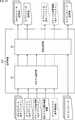
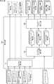
- the playback device 28includes a transmission / reception unit 41, a decoding unit 42, a drawing unit 43, a virtual viewpoint detection unit 44, and an input unit 45.
- the transmission / reception unit 41 of the reproduction device 28receives (acquires) an encoded stream obtained by encoding 3D model data of each object supplied from the transmission / reception device 26 and supplies the encoded stream to the decoding unit 42.
- the transmitting and receiving unit 41acquires object specifying information for specifying a predetermined object from the virtual viewpoint detecting unit 44 and transmits the object specifying information to the transmitting and receiving apparatus 26 via the network 27.
- the decoding unit 42decodes the encoded stream supplied from the transmission / reception unit 41 by a method corresponding to the encoding method in the encoding device 25.
- the decoding unit 42supplies, to the drawing unit 43, 3D model data of one or more objects obtained by decoding.
- the drawing unit 43generates an image (object image) of an object from the viewpoint of the virtual camera as a display image based on 3D model data of one or more objects supplied from the decoding unit 42, and supplies the image to the display device 29.
- the virtual viewpoint detection unit 44supplies virtual camera viewing range information indicating a viewing range based on the viewpoint of the virtual camera to the drawing unit 43, and the 3D model of one or more objects supplied from the decoding unit 42 is a virtual camera By perspective projection onto the viewing range of, the image of the object from the viewpoint of the virtual camera is generated.
- the virtual viewpoint detection unit 44detects the viewpoint of the virtual camera, generates virtual camera viewing range information indicating a viewing range based on the virtual camera viewpoint, and supplies the virtual camera viewing range information to the drawing unit 43. In addition, the virtual viewpoint detection unit 44 generates object identification information for identifying one or more objects present in the viewing range of the virtual camera, and supplies the object identification information to the transmission / reception unit 41.
- the virtual viewpoint detection unit 44may detect the viewing position and the viewing range of the viewer by photographing a marker or the like attached to the head mounted display as the display device 29.
- the input unit 45is configured of an input device such as a controller or a mouse.
- the input unit 45receives, for example, an instruction of a viewing position by a viewer, specification of an object to be displayed, and the like.
- the various input information accepted by the input unit 45is supplied to each unit in the reproduction device 28 as necessary.
- the display device 29is configured of, for example, a two-dimensional head mounted display (HMD) or a two-dimensional monitor.
- the display device 29two-dimensionally displays the display image supplied from the drawing unit 43.
- the display device 29may be configured by a three-dimensional head mounted display, a three-dimensional monitor, or the like.
- the drawing unit 43supplies a depth image in addition to the display image
- the display device 29three-dimensionally displays the display image based on the display image and the depth image supplied from the drawing unit 43.
- the selection device 24selects and selects only the objects that satisfy the predetermined condition from all the objects included in the imaging space stored in the storage device 23.
- the 3D model data of the extracted objectis transmitted to the reproduction device 28.
- the playback device 28acquires 3D model data of an object that satisfies a predetermined condition among all objects included in the imaging space stored in the storage device 23, and based on the acquired 3D model data of the object, An object image is generated and displayed on the display device 29.
- the distribution side and the reproduction sidetransmit only the 3D model data of the objects necessary for display, thereby securing the image quality of the object image to be viewed by the viewer while the reproduction side
- the transmission bandwidthIn addition to reducing the processing load on the network, it is possible to reduce the transmission bandwidth.
- FIG. 5shows a configuration example of the selection device 24A as the first embodiment of the selection device 24. As shown in FIG.
- the selection device 24Aincludes a 3D model selection unit 61A.
- a point cloud format and a UV texture geometry formatare applied as a data format of 3D model data.
- the selection device 24Ais supplied with, as input data, an object ID, which is identification information for identifying each object, and 3D model data, for all the objects stored in the storage device 23.
- 3D model datais geometry information represented by a set of points (point group) and color information for each point, Or, it is one or both of geometry information represented by polygon mesh and color information of each polygon mesh.
- virtual camera viewing range informationwhich is information of a viewing range based on the viewpoint of the virtual camera, which is supplied from the playback device 28 as object specifying information, is also input to the selection device 24A.
- the virtual camera viewing range informationincludes, for example, external parameters and internal parameters of the virtual camera, Near information representing the front clipping plane of the viewing frustum, and Far information representing the rear clipping plane of the viewing frustum.
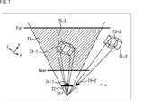
- the 3D model selection unit 61Aselects one of the objects of the virtual camera 70 for all the objects stored in the storage device 23 based on the virtual camera viewing range information supplied from the playback device 28. It is determined whether or not it is included in the viewing range, specifically, in the viewing frustum 71 indicated by hatching, and a 3D model object to be transmitted is selected (decided).
- the 3D model selection unit 61Aprojects each vertex information forming the object on the image plane 72 of the virtual camera 70, and at least one of the UV coordinates corresponding to each vertex information is the image plane of the virtual camera 70.
- itis included in 72, it is determined to be an object for transmitting 3D model data to the reproduction device 28.
- the objectis determined to be an object that does not transmit 3D model data to the reproduction device 28.
- the object 73-1is determined as the object to be transmitted. Since the projection plane 74-2 onto which the object 73-2 is projected is not included in the image plane 72 of the virtual camera 70, the object 73-2 is determined to be an object that is not to be transmitted.
- the image plane 72 of the virtual camera 70is represented by a UV coordinate system.
- the 3D model selection unit 61Aoutputs the object ID of the object selected as the 3D model object to be transmitted to the reproduction device 28 and the 3D model data to the encoding device 25 as output data.
- a representative value of global position information of each objectis calculated in advance and stored in the storage device 23, and only the representative value is projected on the image plane 72 of the virtual camera 70 and transmitted. It may be determined whether or not it corresponds to As a representative value of global position information of an object, for example, an average value of all vertex information of the object can be used.
- a bounding boxis calculated in advance for each object as a representative value of global position information of each object and stored in the storage device 23, and the vertex of the bounding box is the virtual camera 70. It may be projected on the image plane 72 of to determine whether it corresponds to an object of the 3D model to be transmitted.
- FIG. 7shows an example in which the bounding box 75-1 of the object 73-1 and the bounding box 75-2 of the object 73-2 are projected on the image plane 72 of the virtual camera 70.
- FIG. 8is a flowchart illustrating object selection processing (first object selection processing) by the selection device 24A. This process is started, for example, when virtual camera viewing range information is supplied from the playback device 28 via the transmission / reception device 26.
- step S11the 3D model selection unit 61A acquires virtual camera viewing range information based on the viewpoint of the virtual camera 70 supplied from the reproduction device 28 via the transmission / reception device 26.
- step S12the 3D model selection unit 61A acquires, for all objects stored in the storage device 23, an object ID for identifying an object and 3D model data.
- step S13the 3D model selection unit 61A sets a predetermined object as a target object among all the objects acquired from the storage device 23.
- step S14the 3D model selection unit 61A determines whether the object of interest is included in the viewing range of the virtual camera 70.
- the 3D model selection unit 61Aprojects all vertex information forming the object of interest on the image plane 72 of the virtual camera 70, and at least one of UV coordinates corresponding to each vertex information is an image of the virtual camera 70 It is determined whether the surface 72 is included.
- the 3D model selection unit 61Aprojects a representative value of the global position information of the object of interest on the image plane 72 of the virtual camera 70, and at least one of the UV coordinates corresponding to the representative value is a virtual camera It is determined whether it is included in the 70 image plane 72 or not.
- step S14If it is determined in step S14 that the object of interest is included in the viewing range of the virtual camera 70, the process proceeds to step S15, and the 3D model selection unit 61A transmits the object of interest and 3D model data to the reproduction device 28. Decide which transmission object to use.
- step S16the 3D model selection unit 61A outputs the object ID of the transmission object and the 3D model data to the encoding device 25.
- step S14when it is determined in step S14 that the object of interest is not included in the viewing range of the virtual camera 70, steps S15 and S16 are skipped.
- step S17the 3D model selection unit 61A determines whether all objects acquired from the storage device 23 have been set as objects of interest.
- step S17If it is determined in step S17 that all objects have not yet been set as objects of interest, the process returns to step S13, and the above-described processes of steps S13 to S17 are repeated. That is, it is determined whether an object not yet set as the object of interest is set as the next object of interest and is an object included in the viewing range of the virtual camera 70.
- step S17if it is determined in step S17 that all objects have been set as the object of interest, the first object selection process ends.
- the 3D model data of the object within the viewing range of the virtual camera 70is transmitted to the reproduction device 28, so that only the 3D model data of the object necessary for generating the display image is transmitted. ,
- the transmission bandcan be reduced.
- FIG. 9shows a configuration example of a selection device 24B as a second embodiment of the selection device 24. As shown in FIG.
- the selection device 24Bincludes a 3D model selection unit 61B.
- the selection device 24Bone or both of a point cloud format and a UV texture geometry format are applied as a data format of 3D model data. Therefore, as in the first embodiment, the 3D model data is either geometry information represented by a set of points (point group) and color information for each point, or geometry information represented by a polygon mesh and each polygon It is one or both of color information for each mesh.
- not the virtual camera viewing range information based on the viewpoint of the virtual camera but the object ID of the object specified as the display target by the vieweris supplied from the reproducing device 28 to the selecting device 24B as the object specifying information.
- the 3D model selection unit 61Bfirst transmits the object ID and global position information of all the objects stored in the storage device 23 to the playback device 28.
- the minimum value xmin and maximum value xmax of the x coordinate of the vertex of the bounding box, the minimum value ymin and maximum value ymax of the y coordinate, and The minimum value zmin and the maximum value zmax of the z coordinatecan be adopted.
- the object IDs of one or more objects designated by the viewerare used as object specifying information in place of the virtual camera viewing range information based on the viewpoint of the virtual camera in the first embodiment. It is sent from 28.
- object identification informationrepresenting 1, 3 and 5 as object IDs is transmitted from the reproduction device 28 to the selection device 24B.
- the 3D model selection unit 61B of the selection device 24Btransmits, based on the object identification information transmitted from the reproduction device 28, the objects whose object IDs are 1, 3 and 5 and 3D model data to the reproduction device 28 Decide on an object. Then, the 3D model selection unit 61 B acquires 3D model data of each object determined as a transmission object, that is, geometry information and color information from the storage device 23, and supplies this to the encoding device 25.
- FIG. 12is a flowchart illustrating object selection processing (second object selection processing) by the selection device 24B. This process is started, for example, when the playback device 28 is powered on and the viewer performs an operation to start playback.
- step S31the 3D model selection unit 61B acquires object IDs and global position information of all objects stored in the storage device 23.
- step S32the 3D model selection unit 61B transmits the object IDs and global position information of all the acquired objects to the reproduction device 28.
- Object IDs and global position information of all objectsare output from the 3D model selection unit 61 to the encoding device 25 and transmitted to the reproduction device 28 via the encoding device 25, the transmission / reception device 26 and the like.
- step S33the 3D model selection unit 61B acquires the object identification information transmitted from the reproduction device 28 via the transmission / reception device 26.
- step S34the 3D model selection unit 61B determines a transmission object for transmitting 3D model data to the reproduction device 28 based on the object identification information.
- step S35the 3D model selection unit 61B outputs the object ID of the transmission object and the 3D model data to the encoding device 25.
- the 3D model data of the object designated by the viewer as the display targetis transmitted to the reproduction device 28, so that the viewer can designate display or non-display in object units. Further, the transmission band can be reduced by transmitting only 3D model data of an object designated by the viewer as a display target.
- FIG. 13shows a configuration example of a selection device 24C as a third embodiment of the selection device 24. As shown in FIG.
- the selection device 24Cincludes a 3D model selection unit 61 and an image selection unit 81.
- the selection device 24Ca multi-texture geometry format is applied as a data format of 3D model data. Therefore, the 3D model data is represented by geometry information represented by a polygon mesh and captured images (texture images) of the same number as the number of imaging devices 21.
- the 3D model selection unit 61is configured by the 3D model selection unit 61A of the first embodiment described above or the 3D model selection unit 61B of the second embodiment described above, and all of the storage devices 23 are stored. From among the objects, select only those objects that meet a predetermined condition, and determine them as a transmission object.
- the 3D model selection unit 61acquires virtual camera viewing range information as object identification information from the reproduction device 28,
- the transmission objectis determined from among all the objects stored in the storage device 23 based on the virtual camera viewing range information.
- the 3D model selection unit 61acquires object identification information representing an object designated by the viewer from the playback device 28, and is based on the object identification information. Then, the transmission object is determined from among all the objects stored in the storage device 23.
- the object ID as object specifying information which is input data and the output position data of the object ID and the global position information of all the objects stored in the storage device 23 which are indicated by the broken line in FIG.Shows input / output data when the 3D model selection unit 61B is configured.
- the 3D model selection unit 61supplies the determined object ID and 3D model data of the transmission object and the global position information of all objects to the image selection unit 81.
- camera parameters of all the imaging devices 21are supplied from the storage device 23 to the image selection unit 81.
- the 3D model datais configured by geometry information of the polygon mesh and the same number of photographed images as the number of imaging devices 21.
- the same number of captured images as the number of imaging devices 21 that is a part of the 3D model datathere may be a case where an image not including the transmission object determined by the 3D model selection unit 61 exists.
- the image selection unit 81selects only a captured image including the transmission object from among a plurality of (the same number as the number of imaging devices 21) captured images that are a part of 3D model data of the transmission object.
- the 3D model selection unit 61selects one of the three objects 91-1 to 91-3 included in the viewing range of the virtual camera 70, according to the designation by the viewer. Is determined to be a transmission object.
- the two objects 91-1 and 91-3are objects which are not transmitted to the reproduction device 28 (hereinafter, referred to as non-transmission objects).
- the image selection unit 81projects vertex information constituting the object 91-2 on the image plane of each of the plurality of imaging devices 21, and the object 91-2 is included in the image plane. In other words, it is determined whether the object 91-2 is included in the captured image.
- a captured image captured by the imaging device 21-1 and the imaging device 21-2is determined to be a captured image to be transmitted (hereinafter, referred to as a transmission captured image).
- the captured image captured by the imaging device 21-3is a captured image not to be transmitted (hereinafter referred to as a non-transmission captured image). It is determined.
- each imaging device 21in order to reduce the load of calculation, it is included in the captured image captured by each imaging device 21 using the representative value of the global position information of each object, such as the vertex coordinates of the bounding box. It may be calculated whether or not to determine an image to be transmitted.
- 3D model data of one transmission objecthas the same number as one polygon mesh as geometry information and the number of imaging devices 21 as color information, ie, seven images
- the image selection processis performed by the image selection unit 81, the captured image captured by the imaging device 21-3 and the imaging device 21-6 is determined as a captured image not to be transmitted (it is not selected. ).
- the image selection unit 81outputs the object ID of the transmission object and the 3D model data to the encoding device 25.
- the 3D model datais only the photographed image including the transmission object among the photographed images of the same number as the number of imaging devices 21 regarding the color information.
- the image selection unit 81also outputs camera parameters of the imaging device 21 corresponding to the captured image to be transmitted as 3D model data to the encoding device 25.
- FIG. 16is a flowchart illustrating object selection processing (third object selection processing) by the selection device 24C. This process is started, for example, when the playback device 28 is powered on and the viewer performs an operation to start playback.
- step S51the 3D model selection unit 61 executes transmission object determination processing for determining a transmission object from among all objects stored in the storage device 23.
- step S51the 3D model selection unit 61 determines whether the transmission object is determined based on virtual camera viewing range information as object identification information.
- the second object selection process of FIG. 12is performed to determine the transmission object based on the object specifying information representing the selected object.
- the object ID of the transmission object obtained as a result of the processing and the 3D model dataare supplied to the image selection unit 81.
- step S ⁇ b> 52the image selection unit 81 acquires camera parameters of all the imaging devices 21 from the storage device 23.
- step S53the image selection unit 81 sets one of the transmission objects as a target object of interest.
- step S54the image selection unit 81 determines whether the object of interest is included in each of the captured images captured by the plurality of imaging devices 21.
- step S54If it is determined in step S54 that the object of interest is included in at least one of the captured images captured by the plurality of imaging devices 21, the process proceeds to step S55, and the image selection unit 81 performs imaging in which the object of interest is included. An image is determined as a transmission image. On the other hand, the photographed image not including the object of interest is determined as the non-transmission photographed image.
- step S56the image selection unit 81 outputs the object ID of the object of interest and the 3D model data to the encoding device 25.
- the 3D model datais only the photographed image determined as the transmission photographed image in step S55 among the seven photographed images that are the same as the number of imaging devices 21.
- the image selection unit 81also outputs camera parameters of the imaging device 21 corresponding to the transmission captured image to the encoding device 25.
- step S54when it is determined in step S54 that the object of interest is not included in all captured images captured by the plurality of imaging devices 21, the processing in steps S55 and S56 is skipped.
- step S57the image selection unit 81 determines whether all transmission objects have been set as objects of interest.
- step S57If it is determined in step S57 that all the transmission objects have not been set as the target object, the process returns to step S53, and the above-described processes of steps S53 to S57 are repeated. That is, a transmission object not yet set as the object of interest is set as the next object of interest, and the respective photographed images taken by the plurality of imaging devices 21 are transmission photographed images or non-transmission photographed images. It is judged whether there is any.
- step S57if it is determined in step S57 that all transmission objects have been set as the object of interest, the third object selection process ends.
- each captured image captured by the plurality of imaging devices 21is It may be determined simultaneously for all transmission objects whether it is a transmission photographed image or a non-transmission photographed image.
- the third object selection processonly the 3D model data of the object identified by the object identification information is transmitted to the reproduction device 28, so that the transmission band can be reduced.
- the captured image not including the object identified by the object identification informationis not transmitted as a non-transmission captured image, so that the transmission band can be further reduced.
- FIG. 17shows a configuration example of a selection device 24D as a fourth embodiment of the selection device 24. As shown in FIG.
- the multi-texture geometry formatis applied as a data format of 3D model data.
- the selection device 24Dincludes a 3D model selection unit 61, an image selection unit 81, and a cutout unit 100.
- the selection device 24D according to the fourth embodimenthas a configuration in which the cutout unit 100 is added.
- the other configuration of the fourth embodimentis the same as that of the third embodiment.
- the 3D model data of the third embodimentdiffers from the 3D model geometry of the fourth embodiment. , Cropped image and Cropped information metadata has been changed.
- the 3D model geometryrepresents geometry information represented by a polygon mesh included in the 3D model data of the third embodiment. Therefore, there is no difference between the third embodiment and the fourth embodiment as to geometry information of the 3D model data.
- the captured image including the transmission objectwhich is the output data of the third embodiment, cuts out the transmission object portion from the captured image including the transmission object. It has been changed to a cutout image and cutout information metadata which is information indicating the position of the cutout area.
- the third embodiment and the fourth embodimentare similar to the input data.
- the cropping unit 100includes an object area setting unit 101 and a cropped image generation unit 102.
- the cutout unit 100generates a cutout image by cutting out the image of the cutout area including the transmission object from the captured image including the transmission object supplied from the image selection unit 81.
- cutting out an imagemeans cutting out a portion of the image, for example, cutting out a necessary portion of the image, and is also referred to as cropping.
- the object area setting unit 101sets an object area including the transmission object in the captured image including the transmission object based on the 3D model represented by the 3D model data.
- the cutout image generation unit 102generates a cutout image by cutting out the image of the object area from the photographed image.
- the cutout image generation unit 102generates cutout information metadata indicating the position of the cutout area in the captured image.
- the cutout image generation unit 102supplies the cutout image, the cutout information metadata, and the camera parameters of each imaging device 21 to the encoding device 25.
- FIG. 18The cutout process performed by the cutout unit 100 will be described with reference to FIGS. 18 to 21.
- the photographed image supplied from the image selecting unit 81 to the cutout unit 100is a photographed image including a transmission object as shown in FIG.
- FIG. 18is the same as FIG. 15 shown in the description of the third embodiment.
- the photographed images captured by the imaging devices 21-1, 21-2, 21-4, 21-5, and 21-7are transmission captured images. , And supplied to the cutout unit 100.
- the captured image captured by the imaging devices 21-3 and 21-6 and not including the transmission objectis not supplied to the cutout unit 100.
- the cutout unit 100generates a cutout image by cutting out the image of the cutout area including the transmission object from the captured image including the transmission object supplied from the image selection unit 81.
- an object 1(as a transmission object) is provided for five captured images captured by the imaging devices 21-1, 21-2, 21-4, 21-5, and 21-7. Assume that three objects, Object 1), Object 2 (Object 2), and Object 3 (Object 3), are included. The objects 1 to 3 are all portions corresponding to the player.
- the cutout unit 100generates cutout images cr11 to cr13 respectively including the objects 1 to 3 from the captured image captured by the imaging device 21-1.
- the cutout unit 100generates cutout images cr21 to cr23 respectively including the objects 1 to 3 from the photographed image captured by the imaging device 21-2.
- the cutout unit 100generates cutout images cr41 to cr43 respectively including the objects 1 to 3 from the captured image captured by the imaging device 21-4.
- the cutout unit 100generates cutout images cr51 to cr53 including the objects 1 to 3, respectively, from the captured image captured by the imaging device 21-5.
- the cutout unit 100generates cutout images cr71 to cr73 including the objects 1 to 3, respectively, from the captured image captured by the imaging device 21-7.
- the resolutions of the cutout images cr11 to cr73 including any of the objects 1 to 3may be the same resolution or may be changed.
- the cutout images of the photographed image captured at the position closest to the position of the virtual camera 70are set to high resolution
- the cut-out image of the captured image ofcan be reduced in resolution
- the imaging device 21 imaged at the position closest to the position of the virtual camera 70is the imaging device 21-2, and cutout images cr21 to cr23 cut out from the photographed image imaged by the imaging device 21-2. Is set to a high resolution, and the other clipped images cr11 to cr13 and the clipped images cr41 to cr73 are set to be lower in resolution than the clipped images cr21 to cr23.
- low resolution and high resolutionmay be changed in object units.
- the cropped images cr11 to cr71 of the object 1may have high resolution
- the cropped images cr12 to cr72 of the object 2 and the cropped images cr13 to cr73 of the object 3may have low resolution.
- the resolution of the cutout imagemay be adaptively changed and transmitted according to resources such as the network bandwidth and the load on the distribution side and the reproduction side.
- step S71the object area setting unit 101 selects a predetermined one of the transmission photographed images, which are the photographed images including the transmission object, supplied from the image selecting unit 81.
- step S72the object area setting unit 101 selects one of the transmission objects included in the selected transmission photographed image.
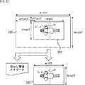
- step S73the object area setting unit 101 sets an object area including the selected transmission object in the transmission photographed image. For example, as shown in FIG. 22, a rectangular area including the transmission object 281 is set in the object area 282 for the transmission photographed image 280.
- step S74the cutout image generation unit 102 generates a cutout image by cutting out the image of the object area from the captured image.
- step S75the cutout image generation unit 102 generates cutout information metadata indicating the position of the cutout area in the captured image.
- FIG. 23shows an example in which the object area 282 is set in the transmission photographed image 280 and the cutout image 283 is cut out.
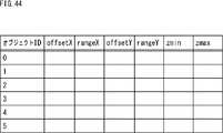
- the cutout image generation unit 102calculates each parameter included in the cutout information metadata according to the following equations (1) to (4).
- width ′is the width of the transmission image 280
- height ′is the height of the transmission image 2801.
- rangeXis the width of the object area 282
- rangeYis the height of the object area 282.
- offsetXis a distance in the X direction (width direction) between the upper left corner of the transmission captured image 280 and the upper left corner of the object area 282
- offsetYis the upper left corner of the transmission captured image 280 and the upper left corner of the object area 282 Distance in the Y direction (height direction) between
- occupancy Xindicates the occupancy rate of the object area 282 in the transmission captured image 280 in the X direction
- occupancyYindicates the occupancy rate of the object area 282 in the transmission captured image 280 in the Y direction.
- normOffsetXis a parameter obtained by normalizing offsetX
- normOffsetYis a parameter obtained by normalizing offsetY.
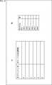
- FIG. 24shows a specific example of cutout information metadata.
- normOffsetX, occupancyX, normOffsetY, and occupancyYare set to 0.05, 0.5, 0.01, and 0.5, respectively.
- step S76the object area setting unit 101 determines whether all transmission objects included in the selected transmission photographed image have been selected.
- step S76If it is determined in step S76 that all of the transmission objects included in the selected transmission photographed image have not been selected, the process returns to step S72, and the above-described processes of steps S72 to S76 are repeated. That is, the next transmission object included in the selected transmission photographed image is selected, and the same processing is performed.
- step S76when it is determined in step S76 that all the transmission objects included in the selected transmission photographed image have been selected, the process proceeds to step S77.
- step S77the object area setting unit 101 determines whether all the transmission photographed images supplied from the image selecting unit 81 have been selected.
- step S77If it is determined in step S77 that all the transmission photographed images have not been selected yet, the process returns to step S71, and the above-described processes of steps S71 to S77 are repeated. That is, the next transmission photographed image which has not been selected yet is selected from among the transmission photographed images supplied from the image selection unit 81, and the same processing is executed.
- step S77when it is determined in step S77 that all the transmission photographed images have been selected, the processing proceeds to step S78, and the cutout unit 100 generates the cutout image and the cutout information metadata thereof and the imaging devices 21.
- the camera parametersare output to the encoding device 25, and the extraction processing is ended.
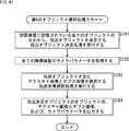
- FIG. 25is a flowchart illustrating object selection processing (fourth object selection processing) by the selection device 24D. This process is started, for example, when the playback device 28 is powered on and the viewer performs an operation to start playback.
- step S91the 3D model selection unit 61 executes a transmission object determination process of determining a transmission object from among all the objects stored in the storage device 23.
- step S91the 3D model selection unit 61 determines whether the transmission object is determined based on virtual camera viewing range information as object identification information.
- the second object selection process of FIG. 12is performed to determine the transmission object based on the object specifying information representing the selected object.
- the object ID of the transmission object obtained as a result of the processing and the 3D model dataare supplied to the image selection unit 81.
- step S 92the image selection unit 81 acquires camera parameters of all the imaging devices 21 from the storage device 23.
- step S93the image selection unit 81 executes transmission photographed image selection processing for selecting a transmission photographed image which is a photographed image including the transmission object from among the photographed images having the same number as the number of imaging devices 21.
- the image selection unit 81executes the processing of steps S53 to S57 of FIG.
- step S94the cutting out unit 100 executes a cutting out process of generating a cut out image obtained by cutting out the image of the object area from the one or more transmission photographed images and cutting out information metadata indicating the position of the cut out area.
- the cutting out unit 100executes the processes of steps S71 to S77 in FIG.
- step S95the selection device 24D outputs the object ID of the transmission object, the 3D model geometry, the cutout image, the cutout information metadata, and the camera parameter to the encoding device 25, and ends the processing.
- the object ID of the transmission object and the 3D model geometryare output from the 3D model selection unit 61, and the cutout image, the cutout information metadata, and the camera parameter are output from the cutout unit 100.
- the transmission bandcan be further reduced.
- the transmission bandcan be further reduced than transmitting the photographed image as it is.
- FIG. 26shows a configuration example of a selection device 24E as a fifth embodiment of the selection device 24.
- the multi-texture geometry formatis applied as in the third embodiment.
- the selection device 24Eincludes a 3D model selection unit 61, an image selection unit 81, a cutout unit 100, a cutout image selection unit 300, and a packing unit 320.
- the selection device 24E according to the fifth embodimenthas a configuration in which a cutout image selection unit 300 and a packing unit 320 are added.
- the other configuration of the fifth embodimentis the same as that of the fourth embodiment.
- the cut-out image selection unit 300selects the cut-out image such that the cut-out image to be transmitted to the reproduction device 28 as reproduction data is equal to or less than Q (Q> 0) sheets preset by a setting unit or the like (not shown). In the case where the number of cut-out images supplied from the cut-out unit 100 for one transmission object is Q or more, it is reduced to Q cut-out images in the cut-out image selection unit 300 and is smaller than Q The number of cut-out images as supplied from the cut-out unit 100 is supplied to the packing unit 320.
- the cutout image selection unit 300includes an importance setting unit 301 and a reproduction data selection unit 302.
- camera parameters of a virtual cameraare also supplied to the selection device 24 ⁇ / b> E.
- the importance setting unit 301sets the importance of each imaging device 21 based on the camera parameter of each imaging device 21 and the camera parameter of the virtual camera.
- the reproduction data selection unit 302selects Q or less cutout images based on the importance of each imaging device 21. Also, the reproduction data selection unit 302 sets the importance of the imaging device 21 used for imaging as the importance of each selected cutout image. The reproduction data selection unit 302 supplies the selected cutout image and its importance, and cutout information metadata and camera parameters corresponding to the cutout image to the packing unit 320.
- the packing unit 320generates a packed image by packing a plurality of cut-out images into one image.
- the packing unit 320includes a packing image generation unit 321 and a metadata generation unit 322.
- the packing image generation unit 321sets a packing layout, which is a layout for packing each cutout image, using the degree of importance of each cutout image as necessary. Then, the packing image generation unit 321 generates a packing image by mapping each cutout image to each packing area in the packing layout, using the degree of importance of each cutout image as necessary, and the encoding device 25 Supply to The unit of packing may be for each imaging device 21 or each transmission object. Alternatively, all cropped images may be packed as one packed image.
- the metadata generation unit 322generates packing information metadata indicating the position at which the cutout image is mapped.
- the metadata generation unit 322supplies the encoding device 25 with cutout information metadata, packing information metadata, and camera parameters of each cutout image included in the packed image.
- reproduction data selection processThe reproduction data selection process executed by the cutout image selection unit 300 will be described with reference to the flowchart of FIG.
- the importance setting unit 301acquires camera parameters of the virtual camera from the reproduction device 28 via the transmission / reception device 26 and the like. Further, the importance setting unit 301 acquires camera parameters of each imaging device 21 from the cutout unit 100.
- the camera parameters of the virtual camerainclude, for example, parameters of the same type as the camera parameters of the imaging device 21.
- step S122the importance setting unit 301 selects one of the transmission objects.
- step S123the importance setting unit 301 sets 1 to the variable i.
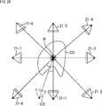
- the degree of importance P (i)is calculated based on, for example, the relative relationship of at least one of the position and the direction between each imaging device 21 (the actual viewpoint) and the virtual camera.
- Cirepresents a vector from the imaging device 21-i to the object 331.
- Cvindicates a vector from the virtual camera 332 to the object 331.
- Ci ⁇ Cvindicates the inner product of the vector Ci and the vector Cv.
- the importance degree P (i)is inversely proportional to the angle between the vector Ci and the vector Cv, and the importance degree P (i) increases as the angle between the vector Ci and the vector Cv decreases. That is, the importance degree P (i) becomes higher as the imaging device 21 whose direction with respect to the object 331 is closer to the virtual camera 332.
- the vector Ci and the vector Cvare set with reference to the representative point R of the object 331.
- the representative point Rcan be set by any method. For example, a point on the object 331 at which the sum of the distances from the optical axes of the imaging devices 21 and the virtual camera 332 is minimum is set as the representative point R. Alternatively, for example, a central position between the maximum value and the minimum value of the coordinates of the vertex of the object 331 in each direction of the world coordinate system in the X direction, the Y direction, and the Z direction is set as the representative point R. Alternatively, for example, the most important position in the object 331 is set as the representative point R. For example, when the object 331 is a person, the center of the person's face or the like is set as the representative point R.
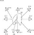
- FIG. 29illustrates an example in which the degree of importance P (i) is calculated based on the relationship between the optical axis of each imaging device 21 (the direction of the actual viewpoint) and the optical axis of the virtual camera 332 (the direction of the virtual viewpoint). It shows.
- the degree of importance P (i)is calculated by the following equation (8).
- P (i)Zi ⁇ Zv (8)
- Ziindicates the optical axis vector of the imaging device 21-i.
- Zvindicates an optical axis vector of the virtual camera 332.
- Zi ⁇ Zvindicates the inner product of the optical axis vector Zi and the optical axis vector Zv.
- the degree of importance P (i)is inversely proportional to the angle between the optical axis vector Zi and the optical axis vector Zv, and the smaller the angle between the vector Zi and the vector Zv, the higher the degree of importance P (i). That is, as the direction of the optical axis is closer to the virtual camera 332, the importance degree P (i) becomes higher.
- FIG. 30illustrates an example of calculating the importance degree P (i) based on the distance between each imaging device 21 and the virtual camera 332.
- the degree of importance P (i)is calculated by the following equation (9).
- P (i)1-Di / ⁇ Di (9)
- Direpresents the distance between the imaging device 21-i and the virtual camera 332.
- the importance setting unit 301may set the importance by combining two or more of the three types of importance P (i) described above.
- the importance setting unit 301may set the importance based on the content of the captured image captured by each imaging device 21. For example, the importance of the imaging device 21 closer to the front of the object to be displayed may be increased. Alternatively, for example, when the object to be displayed is a person, the degree of importance of the imaging device 21 that has captured a captured image in which a face is captured may be increased.
- step S125the importance setting unit 301 increments the variable i by one.
- step S126the importance setting unit 301 determines whether the variable i is equal to or less than N.
- Nis the number of imaging devices 21. If it is determined that the variable i is equal to or less than N, the process returns to step S124.
- step S126the process of steps S124 to S126 is repeatedly performed until it is determined that the variable i is larger than N.
- the importance P (i) of all the imaging devices 21-iis calculated.
- step S126when it is determined in step S126 that the variable i is larger than N, the process proceeds to step S127.
- step S127the reproduction data selection unit 302 selects reproduction data based on the degree of importance P (i). That is, the reproduction data selection unit 302 selects Q cut-out images from the imaging device 21 having the higher degree of importance P (i).
- all of the cut-out images captured by the imaging device 21 whose importance degree P (i) is equal to or more than a predetermined thresholdmay be selected. In this case, the number of selected cutout images is not fixed.
- the reproduction data selection unit 302sets the importance P (i) of the imaging device 21 that has captured the cut-out image as the importance of each cut-out image.
- step S128the reproduction data selection unit 302 determines whether all transmission objects have been selected.
- step S128If it is determined in step S128 that all transmission objects have not been selected, the process returns to step S122, and the above-described processes of steps S122 to S127 are repeated. That is, the next transmission object is selected, and the same processing is performed.
- step S128determines whether all the transmission objects have been selected. If it is determined in step S128 that all the transmission objects have been selected, the process proceeds to step S1129, and the reproduction data selection unit 302 selects the selected cutout image and its importance, and cutout information corresponding to the cutout image.
- the metadata and camera parametersare supplied to the packing unit 320, and the reproduction data selection process ends.
- step S151the packing image generation unit 321 sets a packing layout.
- the packing layoutthe layout of the packing area for mapping the cutout image is shown in the same rectangular area as the packing image.
- the packing layoutis set based on the number of cutout images to be selected (hereinafter referred to as the selection number) and the importance of each cutout image.
- the packing layoutis set based on the selection number. For example, a packing layout is set in which a rectangular area of the same size as the packing image is divided into packing areas for the number of selections. At this time, the shape and size of each packing area may be the same or different. In the latter case, for example, a packing area to which a cutout image with a high degree of importance is mapped is larger.
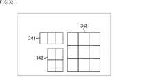
- FIG. 32shows an example of a packing layout in which packing areas of the same shape and size are arranged in a lattice.
- packing layout 341rectangular packing areas of the same shape and size are arranged in vertical 1 row ⁇ horizontal 3 columns. In the packing layout 342, rectangular packing areas of the same shape and size are arranged in vertical 2 rows ⁇ horizontal 2 columns. In the packing layout 343, rectangular packing areas of the same shape and size are arranged in vertical 3 rows ⁇ horizontal 3 columns.
- the packing layoutmay be fixed or may be changed as needed.
- the shape and size of each packing areamay be the same or different.
- the shape or size of each packing areais different, for example, the packing area to which a cutout image with a high degree of importance is mapped is larger.
- the packing layoutis variable, for example, the size of each packing area is set in accordance with the importance of each cutout image. For example, the packing area to which a cutout image with a high degree of importance is mapped is larger.
- step S152the packing image generation unit 321 sets 1 to the variable i.
- step S153the packing image generation unit 321 determines whether it is a grid-like packing layout. When the packing areas having the same shape and size are not arranged in a lattice in the set packing layout, the packing image generation unit 321 determines that the packing layout is not a lattice packing, and the process proceeds to step S154.
- the metadata generation unit 322generates metadata of the packing area i. Specifically, in the case of a non-grid packing layout, the packing information metadata includes a plurality of packing area metadata corresponding to each packing area. Then, the metadata generation unit 322 generates packing area metadata corresponding to the packing area i.
- FIG. 33shows an example of a non-grid packing layout.
- packing areas of the same shape and sizeare arranged in one vertical row ⁇ three horizontal columns above and below the large central packing area.
- each parameter of packing area metadata of the packing area 362 indicated by hatching of the packing layout 361is calculated by the following equations (10) to (13).
- width ′is the width of the packing layout 361 (packing image), and height ′ is the height of the packing layout 361.
- rangeXis the width of the packing area 362, and rangeY is the height of the packing area 362.
- offsetXis a distance in the X direction (width direction) between the upper left corner of the packing layout 361 and the upper left corner of the packing area 362, and offsetY is between the upper left corner of the packing layout 361 and the upper left corner of the packing area 362 Distance in the Y direction (height direction) of
- occupancy Xindicates the occupancy of the packing area 362 in the packing layout 361 (packing image) in the X direction
- occupancyYindicates the occupancy of the packing area 362 in the packing layout 361 in the Y direction.
- normOffsetXis a parameter obtained by normalizing offsetX
- normOffsetYis a parameter obtained by normalizing offsetY.
- step S155the packing image generation unit 321 selects a cutout image to be mapped to the packing area i.
- the packing image generation unit 321selects the cutout image such that the cutout image with higher importance is mapped to a larger packing area.
- the packing image generation unit 321selects a cutout image having a shape close to the shape of the packing area i.
- the metadata generation unit 322adds an ID (identification information) indicating the imaging device 21 corresponding to the selected cutout image to the packing area metadata.
- FIG. 34shows a specific example of packing area metadata.
- normOffsetX, occupancyX, normOffsetY, and occupancyYare set to 0.33, 0.33, 0.8, and 0.2, respectively.
- camera_idis set to 1.
- the camera_idis a parameter indicating the ID of the imaging device 21 corresponding to the cutout image mapped to the packing area.
- step S155After the cutout image to be mapped to the packing area i is selected in step S155 and the ID of the imaging device 21 is added to the packing area metadata corresponding to the packing area i, the process proceeds to step S157.
- step S153determines whether the packing layout is lattice-like. If it is determined in step S153 that the packing layout is lattice-like, the process proceeds to step S156.
- step S156the packing image generation unit 321 selects the cutout image to be mapped to the packing area i, as in the process of step S155. Further, the metadata generation unit 322 adds the ID of the imaging device 21 corresponding to the selected cutout image to the packing information metadata.
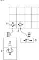
- FIG. 35shows an example of packing information metadata corresponding to a grid-like packing layout.
- FIG. 35shows an example of the packing layout.
- packing areas of the same shape and sizeare arranged in a grid of 4 rows ⁇ 3 columns.
- the right side of FIG. 35shows an example of packing information metadata generated for the packing layout on the left side.
- 4is set in a parameter raw representing the number of rows in the packing layout
- 3is set in a parameter representing the number of columns.
- a parameter camera_id indicating the ID of the imaging device 21 corresponding to the cutout image mapped to each packing areais set.
- the camera_id of the first row packing area of the first rowis set to 2
- the camera_id of the second row packing area of the first lineis set to 1
- the metadata generation unit 322sets the values of the parameters raw and column in the process of the first step S156 in the loop. Further, in the process of step S156 in each loop, the metadata generation unit 322 sets the ID of the imaging device 21 corresponding to the cutout image to the parameter camera_id corresponding to the packing area to which the cutout image is mapped.
- step S156after the cutout image to be mapped to the packing area i is selected and the ID of the imaging device 21 is added to the packing information metadata, the process proceeds to step S157.
- step S157the metadata generation unit 322 determines whether the variable i is equal to or less than M.
- Mrepresents the number of packing areas in the packing layout.
- step S157If it is determined in step S157 that the variable i is equal to or less than M, the process returns to step S153, and the process from step S153 to step S157 is repeatedly performed until it is determined in step S157 that the variable i is larger than M. Be done. Thus, the cutout image to be mapped to each packing area in the packing layout is selected, and packing information metadata is generated.
- step S157if it is determined in step S157 that the variable i is larger than M, the process proceeds to step S158.
- step S158the packing image generation unit 321 generates a packing image. Specifically, the packing image generation unit 321 maps each cut image to each packing area of the packing layout. This generates a packed image in which a plurality of cut-out images are combined into one.
- a cutout image cut out of nine photographed images of 1080 pixels in height ⁇ 1920 pixels in widthhas packing areas of 540 pixels in height ⁇ 960 pixels in width of 3 rows ⁇ 3 rows It is mapped to each arranged packing layout. Thereby, nine cut images are combined into one packed image.
- the packing image generation unit 321performs enlargement / reduction of the cutout image in order to adjust the size of each cutout image to the size of the packing area to be mapped. For example, as shown in FIG. 37, when the cutout image 381 is mapped to the packing area 391, the vertical direction and the horizontal direction of the cutout image 381 are reduced. Also, when the cutout image 382 is mapped to the packing area 392, the vertical direction of the cutout image 382 is reduced and the horizontal direction is enlarged.
- the packing image generation unit 321maps each cut image to each packing area of the packing layout. This produces a packed image in which each cut out image is combined into one.
- step S159the packing unit 320 outputs the generated packing image to the coding device 25 together with the cutout information metadata of each cutout image, the packing information metadata of the packing image, and the camera parameter, and the packing processing is performed. finish.
- FIG. 38is a flowchart for describing object selection processing (fifth object selection processing) by the selection device 24E. This process is started, for example, when the playback device 28 is powered on and the viewer performs an operation to start playback.
- step S171the 3D model selection unit 61 executes transmission object determination processing of determining a transmission object from among all objects stored in the storage device 23.
- step S171the 3D model selection unit 61 determines whether the transmission object is determined based on virtual camera viewing range information as object identification information.
- the second object selection process of FIG. 12is performed to determine the transmission object based on the object specifying information representing the selected object.
- the object ID of the transmission object obtained as a result of the processing and the 3D model dataare supplied to the image selection unit 81.
- step S172the image selection unit 81 acquires camera parameters of all the imaging devices 21 and virtual cameras.
- step S173the image selection unit 81 executes transmission photographed image selection processing for selecting a transmission photographed image which is a photographed image including a transmission object from among the photographed images having the same number as the number of imaging devices 21.
- the image selection unit 81executes the processing of steps S53 to S57 of FIG.
- step S174the cropping unit 100 executes cropping processing for creating a cropped image obtained by cropping the image of the object area from one or more transmission photographed images and cropping information metadata indicating the position of the cropped area.
- the cutting out unit 100executes the processes of steps S71 to S77 in FIG.
- the generated cutout image and the cutout information metadata thereof, and the camera parameters of all the imaging devices 21 and virtual camerasare supplied to the cutout image selection unit 300.
- step S175the cut-out image selection unit 300 sets the cut-out image according to the importance of the cut-out image such that the number of cut-out images to be transmitted as reproduction data to the reproduction device 28 becomes a predetermined number (for example, Q or less). Execute the data selection process for reproduction to select. In other words, the cutout image selection unit 300 executes the processing of steps S121 to S129 in FIG.
- step S176the packing unit 320 performs packing processing to generate a packing image by packing the plurality of cutout images selected by the cutout image selection unit 300 into one image.
- the packing unit 320executes the processes of steps S151 to S158 of FIG.
- step S177the selection device 24E outputs the object ID of the transmission object, the 3D model geometry, the packing image, the cutout information metadata, the packing information metadata, and the camera parameters to the encoding device 25, and the fifth End object selection processing.
- the object ID of the transmission object and the 3D model geometryare output from the 3D model selection unit 61, and the packing image, cutout information metadata, packing information metadata, and camera parameters are output from the packing unit 320.
- the transmission bandcan be further reduced.
- the transmission bandcan be further reduced than transmitting the photographed image as it is.
- the number of cut-out imagesis reduced to a predetermined number according to the degree of importance of the cut-out image by the data selection processing for reproduction and packing them into one image by packing processing, transmission is optimum. You can audition in resolution.
- FIG. 39shows a configuration example of a selection device 24F as a sixth embodiment of the selection device 24.
- the color information of the objectis composed of the same number of photographed images as the number of imaging devices 21, and the geometry information of the objects is the same number of depth images as the number of imaging devices 21. Configured, multi-texture depth format is applied.
- the picked-up image as color informationis called and demonstrated as a texture image.
- the selection device 24Fincludes a 3D model selection unit 61 and a texture depth image selection unit 421. That is, the selection device 24F has a configuration in which the texture depth image selection unit 421 is further added to the 3D model selection unit 61 similar to the third embodiment.
- the 3D model selection unit 61is supplied with 3D model data of all objects.
- the 3D model datais composed of the same number of texture images and depth images as the number of imaging devices 21.
- the 3D model selection unit 61determines (selects) a transmission object from among all the objects stored in the storage device 23 based on the object identification information.
- the 3D model selection unit 61supplies the determined 3D model data of the transmission object, that is, a plurality of texture images and depth images, to the texture depth image selection unit 421.
- Camera parameters of all the imaging devices 21are supplied from the storage device 23 to the texture depth image selection unit 421.
- the texture depth image selection unit 421performs the same process as the image selection unit 81 according to the third embodiment shown in FIG. However, while the 3D model data handled by the image selection unit 81 of the third embodiment is data in the multi-texture geometry format, the 3D model data handled by the texture depth image selection unit 421 is in the multi-texture depth format The difference is the data of
- the texture depth image selection unit 421performs transmission image selection processing of selecting the texture image including the transmission object and the depth image from among the texture images and the depth images of the same number as the number of imaging devices 21.
- FIG. 40is a diagram for explaining transmission image selection processing performed by the texture depth image selection unit 421.
- FIG. 40corresponds to FIG. 15 described in the third embodiment.
- dep1 to dep7represent depth images generated by seven imaging devices 21-1 to 21-7.
- the texture depth image selecting unit 421similarly determines the depth image generated by the imaging device 21-3 and the imaging device 21-6 as a depth image not to be transmitted.
- the texture depth image selection unit 421outputs the object ID of the transmission object and the 3D model data to the encoding device 25.
- the 3D model datais a multi-texture depth format represented by a texture image and a depth image, and among the same number of photographed images as the number of imaging devices 21, only the texture image and the depth image including the transmission object .
- the image selection unit 81also outputs, to the encoding device 25, camera parameters of the imaging device 21 corresponding to the texture image and the depth image transmitted as 3D model data.
- FIG. 41is a flowchart for describing object selection processing (sixth object selection processing) by the selection device 24F. This process is started, for example, when the playback device 28 is powered on and the viewer performs an operation to start playback.
- step S191the 3D model selection unit 61 executes transmission object determination processing of determining a transmission object from among all objects stored in the storage device 23.
- step S191the 3D model selection unit 61 determines the transmission object based on the virtual camera viewing range information as the object identification information, or the viewer specifies the first object selection process of FIG.
- the second object selection process of FIG. 12is performed to determine the transmission object based on the object specifying information representing the selected object.
- the object ID and 3D model data of the transmission object obtained as a result of the processingare supplied to the texture depth image selection unit 421.
- step S192the texture depth image selecting unit 421 acquires camera parameters of all the imaging devices 21 from the storage device 23.
- step S193the texture depth image selection unit 421 performs transmission image selection processing for selecting the texture image including the transmission object and the depth image from among the texture images and the depth images of the same number as the number of imaging devices 21.
- step S194the selection device 24F selects the object ID of the transmission object, the 3D model data including the texture image and the depth image including the transmission object, and the camera parameters of the imaging device 21 corresponding to the texture image and the depth image to be transmitted. , And outputs the sixth object selection process.
- the object ID of the transmission objectis output from the 3D model selection unit 61, and the 3D model data and the camera parameter are output from the texture depth image selection unit 421.
- the transmission bandcan be further reduced.
- FIG. 42shows a configuration example of a selection device 24G as a seventh embodiment of the selection device 24.
- the multi-texture depth formatis applied as the data format of the 3D model data, as in the sixth embodiment.
- the selection device 24Gincludes a 3D model selection unit 61, a texture depth image selection unit 421, and a texture depth cutout unit 441.
- the texture depth cutout unit 441is further added to the 3D model selection unit 61 and the texture depth image selection unit 421 similar to the sixth embodiment shown in FIG. 39 in the selection device 24G according to the seventh embodiment. It is assumed that The other configuration of the seventh embodiment is the same as that of the sixth embodiment.
- the texture depth image selecting unit 421supplies a texture image and a depth image including a transmission object, and camera parameters of the imaging device 21 to the texture depth cutting unit 441.
- the texture depth cutout unit 441performs the cutout processing to cut out the image of the object area, similarly to the cutout unit 100 of the fourth embodiment shown in FIG.
- the data format of 3D model datais the multi-texture geometry format expressed by polygon mesh and texture image in the fourth embodiment, it is expressed by texture image and depth image in the seventh embodiment It differs in that it is a multi-texture depth format that is
- the texture depth cutout unit 441generates a texture cutout image by cutting out the image of the object region from the texture image including the transmission object supplied from the texture depth image selection unit 421. .
- the generation of the texture cutout imageis the same as that of the cutout unit 100 of the fourth embodiment.
- the texture depth cutout unit 441generates a depth cutout image by cutting out the image of the object region from the depth image including the transmission object supplied from the texture depth image selection unit 421.
- the texture depth cutout unit 441generates cutout information metadata indicating the position of the cutout region from the texture image and the depth image.
- the texture depth cutout unit 441supplies the texture cutout image and the depth cutout image, the cutout information metadata thereof, and the camera parameters of each imaging device 21 to the encoding device 25.
- FIG. 43is a diagram for explaining a depth image.
- three objects 461 to 463are imaged in the texture cutout image 460.
- the texture depth cutout unit 441generates a depth cutout image for each transmission object.
- the texture depth cutout unit 441generates a depth cutout image 481 for the object 461.
- the depth cut out image 481has the same size as the texture cut out image 460, the pixel value of the area of the object 461 is expressed at a predetermined resolution representing the distance z of the object 461, and the pixel values other than the area of the object 461 are arbitrary fixed values This is an image represented by (0 in the example of FIG. 43).
- the texture depth cutout unit 441generates a depth cutout image 482 for the object 462.
- the depth cut out image 482has the same size as the texture cut out image 460, the pixel value of the area of the object 462 is expressed at a predetermined resolution representing the distance z of the object 462, and the pixel values other than the area of the object 462 are arbitrary fixed values This is an image represented by (0 in the example of FIG. 43).
- the texture depth cutout unit 441generates a depth cutout image 483 for the object 463.
- the depth cut out image 483has the same size as the texture cut out image 460, the pixel value of the area of the object 463 is expressed at a predetermined resolution representing the distance z of the object 463, and the pixel values other than the area of the object 463 are arbitrary fixed values This is an image represented by (0 in the example of FIG. 43).
- the size of the depth cut out imagemay be different for each object.
- the texture depth cutting out unit 441is an object whose pixel value of the region corresponding to the region of the object 461 on the texture cutout image 460 is an object A minimum size depth cut out image 491 of a rectangle including the area representing the distance z of 461 is generated.
- the texture depth cutout unit 441has a rectangular minimum size depth cutout image 492 including an area corresponding to the area of the object 462 on the texture cutout image 460, and the texture cutout image 460 for the object 463.
- a rectangular minimum size depth cutout image 493 including a region corresponding to the region of the upper object 463is generated.
- FIG. 44shows an example of cutout information metadata.
- the positions of the cutout region from the texture image and the depth image in the X direction (width direction) and the Y direction (height direction)are represented by offsetX, rangeX, offsetY, and rangeY described with reference to FIG.
- the position of the cutout areamay be expressed by occupancyX, occupancyY, normOffsetX, or normOffsetY of Equations (1) to (4) divided by the width width ′ or the height height ′ of the texture image and the depth image.
- the clipping information metadata of the seventh embodimentincludes the minimum value z min of the z coordinate and the maximum value z max as clipping information on the depth clipping image.
- FIG. 45is a diagram for explaining the minimum value zmin and the maximum value zmax.
- the minimum value zmin and the maximum value zmaxare stored in the cutout information metadata. .
- FIG. 46is a flowchart for describing object selection processing (seventh object selection processing) by the selection device 24G. This process is started, for example, when the playback device 28 is powered on and the viewer performs an operation to start playback.
- step S231the 3D model selection unit 61 executes transmission object determination processing of determining a transmission object from among all objects stored in the storage device 23.
- step S231the 3D model selection unit 61 determines the transmission object according to the virtual camera viewing range information as the object identification information or the first object selection processing of FIG.
- the second object selection process of FIG. 12is performed to determine the transmission object based on the object specifying information representing the selected object.
- the object ID and 3D model data of the transmission object obtained as a result of the processingare supplied to the texture depth image selection unit 421.
- step S232the texture depth image selecting unit 421 acquires camera parameters of all the imaging devices 21 from the storage device 23.
- step S233the texture depth image selection unit 421 performs transmission image selection processing of selecting a texture image including a transmission object and a depth image from among the texture images and depth images of the same number as the number of imaging devices 21.
- step S234the texture depth cutout unit 441 cuts out the texture image including the transmission object and the object region of the depth image, and performs the cutout processing for generating the texture cutout image and the depth cutout image for each object, and their cutout information metadata. Run.
- step S235the selection device 24G outputs the object ID of the transmission object, 3D model data consisting of the texture cutout image and the depth cutout image for each transmission object, the cutout information metadata, and the camera parameter to the encoding device 25. Then, the seventh object selection process is finished.
- the object ID of the transmission objectis output from the 3D model selection unit 61, and the 3D model data, cutout information metadata, and camera parameters are output from the texture depth cutout unit 441.
- the transmission bandcan be further reduced.
- a transmission bandis more than transmitting a texture image and a depth image as they are. It can be reduced.
- the cutout image and the depth cutout imagemay be further selected, or may be packed into one image and transmitted.
- each of the plurality of imaging devices 21captures a predetermined imaging space, and supplies a moving image obtained as a result to the reconstruction device 22.
- step S302the reconstruction device 22 uses the moving images in the imaging space supplied from each of the imaging devices 21-1 to 21-N to generate a 3D model for each object with respect to a large number of objects existing in the imaging space. Are generated, and the generated 3D model data of each object is supplied to the storage unit 23.
- Arbitrary methodscan be adopted as to what is set as an object in the moving image and how to separate the objects, and each object is appropriately separated, and 3D model data for each object is It is stored in the storage unit 23.
- step S303the selection device 24 acquires, from the transmission / reception device 26, object identification information for identifying an object transmitted from the playback device 28.
- the object identification informationis, for example, virtual camera viewing range information which is viewing range information of a virtual camera, or information of an object ID of an object designated by the viewer as a display target.
- the object ID of each object and the global position informationare transmitted to the playback device 28 in advance.
- step S304the selection device 24 determines (selects) an object to be transmitted out of all objects stored in the storage device 23 based on the object identification information, and the object IDs of the determined one or more objects. And 3D model data to the encoder 25. As the details of this process, any one of the first to seventh object selection processes described above is performed.
- step S305the encoding device 25 encodes the object IDs of the one or more objects determined to be transmitted and the 3D model data according to a predetermined encoding method such as the AVC method, HEVC method, or the like.
- the encoded stream of the 3D model obtained by encodingis supplied to the transmission / reception device 26.
- step S306the transmission / reception device 26 transmits the 3D model coded stream supplied from the coding device 25 to the reproduction device 28 via the network 27.
- a part of 3D modelsis selected from among the 3D models of a large number of objects captured and generated by the plurality of imaging devices 21 so that the playback device 28 reproduces the selected 3D model, 3D model data can be transmitted.
- step S 321the virtual viewpoint detection unit 44 of the playback device 28 generates object identification information that identifies one or more objects present in the viewing range of the virtual camera, and supplies the object identification information to the transmission / reception unit 41.
- the object identification informationis, for example, virtual camera viewing range information which is viewing range information of a virtual camera, or information of an object ID of an object designated by the viewer as a display target.
- object ID informationis acquired as object identification information, the object ID of each object and global position information are transmitted in advance from the transmitting / receiving device 26 to the reproducing device 28.
- step S 322the transmission / reception unit 41 transmits the object identification information supplied from the virtual viewpoint detection unit 44 to the transmission / reception device 26 via the network 27.
- step S 323the transmission and reception unit 41 receives (acquires) an encoded stream obtained by encoding 3D model data of one or more objects supplied from the transmission and reception apparatus 26, and supplies the encoded stream to the decoding unit 42.
- step S324the decoding unit 42 decodes the 3D model encoded stream supplied from the transmission / reception unit 41 by a method corresponding to the encoding method in the encoding device 25.
- the decoding unit 42supplies, to the drawing unit 43, 3D model data of one or more objects obtained by decoding.
- step S325the drawing unit 43 generates an image (object image) of the object from the viewpoint of the virtual camera as a display image based on the 3D model data of the one or more objects supplied from the decoding unit 42, and the display device Supply to 29
- step S326the display device 29 two-dimensionally displays the display image supplied from the drawing unit 43, and ends the reproduction process.
- 3D model data of only objects that satisfy a predetermined condition based on object identification informationis transmitted to the reproduction side Be done.
- the processing load on the reproduction sideis reduced while securing the image quality of the object image viewed by the viewer.
- Transmission bandcan be reduced.
- the transmission bandis reduced by transmitting only 3D model data of objects within the viewing range of the viewer. , Can generate a display image.
- the viewerwhen the information of the object ID of the object specified by the viewer as the display target is adopted as the object specifying information, the viewer can specify the object to be displayed, and the display image with the transmission band reduced is generated. can do.
- the above-described series of processesmay be performed by hardware or software.
- a program that configures the softwareis installed on a computer.
- the computerincludes, for example, a general-purpose personal computer that can execute various functions by installing a computer incorporated in dedicated hardware and various programs.
- FIG. 49is a block diagram showing an example of a hardware configuration of a computer that executes the series of processes described above according to a program.
- a central processing unit (CPU) 901, a read only memory (ROM) 902, and a random access memory (RAM) 903are mutually connected by a bus 904.
- an input / output interface 905is connected to the bus 904.
- An input unit 906, an output unit 907, a storage unit 908, a communication unit 909, and a drive 910are connected to the input / output interface 905.
- the input unit 906includes a keyboard, a mouse, a microphone, and the like.
- the output unit 907includes a display, a speaker, and the like.
- the storage unit 908is formed of a hard disk, a non-volatile memory, or the like.
- the communication unit 909is formed of a network interface or the like.
- the drive 910drives removable media 911 such as a magnetic disk, an optical disk, a magneto-optical disk, or a semiconductor memory.
- the CPU 901loads the program stored in the storage unit 908 into the RAM 903 via the input / output interface 905 and the bus 904 and executes the program. A series of processing is performed.
- the program executed by the computer 900can be provided by being recorded on, for example, a removable medium 911 as a package medium or the like. Also, the program can be provided via a wired or wireless transmission medium such as a local area network, the Internet, or digital satellite broadcasting.
- the programcan be installed in the storage unit 908 via the input / output interface 905 by attaching the removable media 911 to the drive 910.
- the programcan be received by the communication unit 909 via a wired or wireless transmission medium and installed in the storage unit 908.
- the programcan be installed in advance in the ROM 902 or the storage unit 908.
- the program executed by the computer 900may be a program that performs processing in chronological order according to the order described in this specification, or in parallel, or when necessary, such as when a call is made. It may be a program in which processing is performed.
- the technology according to the present disclosurecan be applied to various products.
- the technology according to the present disclosureis any type of movement, such as automobiles, electric vehicles, hybrid electric vehicles, motorcycles, bicycles, personal mobility, airplanes, drones, ships, robots, construction machines, agricultural machines (tractors), etc. It may be realized as a device mounted on the body.
- FIG. 50is a block diagram showing a schematic configuration example of a vehicle control system 7000 that is an example of a mobile control system to which the technology according to the present disclosure can be applied.
- Vehicle control system 7000comprises a plurality of electronic control units connected via communication network 7010.
- the vehicle control system 7000includes a drive system control unit 7100, a body system control unit 7200, a battery control unit 7300, an outside information detection unit 7400, an in-vehicle information detection unit 7500, and an integrated control unit 7600. .
- the communication network 7010 connecting the plurality of control unitsis, for example, an arbitrary standard such as CAN (Controller Area Network), LIN (Local Interconnect Network), LAN (Local Area Network), or FlexRay (registered trademark). It may be an in-vehicle communication network.
- CANController Area Network
- LINLocal Interconnect Network
- LANLocal Area Network
- FlexRayregistered trademark
- Each control unitincludes a microcomputer that performs arithmetic processing in accordance with various programs, a storage unit that stores programs executed by the microcomputer or parameters used in various arithmetic operations, and drive circuits that drive devices to be controlled. Equipped with Each control unit is provided with a network I / F for communicating with other control units via the communication network 7010, and by wired communication or wireless communication with an apparatus or sensor inside or outside the vehicle. A communication I / F for performing communication is provided. In FIG.
- control unit 7600as a functional configuration of the integrated control unit 7600, a microcomputer 7610, a general-purpose communication I / F 7620, a dedicated communication I / F 7630, a positioning unit 7640, a beacon receiving unit 7650, an in-vehicle device I / F 7660, an audio image output unit 7670, An in-vehicle network I / F 7680 and a storage unit 7690 are illustrated.
- the other control unitsalso include a microcomputer, a communication I / F, a storage unit, and the like.
- Drive system control unit 7100controls the operation of devices related to the drive system of the vehicle according to various programs.
- drive system control unit 7100includes a drive force generation device for generating a drive force of a vehicle such as an internal combustion engine or a drive motor, a drive force transmission mechanism for transmitting the drive force to the wheels, and a steering angle of the vehicle. It functions as a control mechanism such as a steering mechanism that adjusts and a braking device that generates a braking force of the vehicle.
- the drive system control unit 7100may have a function as a control device such as an ABS (Antilock Brake System) or an ESC (Electronic Stability Control).
- Vehicle state detection unit 7110is connected to drive system control unit 7100.
- the vehicle state detection unit 7110may be, for example, a gyro sensor that detects an angular velocity of an axial rotational movement of a vehicle body, an acceleration sensor that detects an acceleration of the vehicle, or an operation amount of an accelerator pedal, an operation amount of a brake pedal, and steering of a steering wheel. At least one of the sensors for detecting the angle, the engine speed, the rotational speed of the wheel, etc. is included.
- Drive system control unit 7100performs arithmetic processing using a signal input from vehicle state detection unit 7110 to control an internal combustion engine, a drive motor, an electric power steering device, a brake device, and the like.
- Body system control unit 7200controls the operation of various devices equipped on the vehicle body according to various programs.
- the body control unit 7200functions as a keyless entry system, a smart key system, a power window device, or a control device of various lamps such as a head lamp, a back lamp, a brake lamp, a blinker or a fog lamp.
- the body system control unit 7200may receive radio waves or signals of various switches transmitted from a portable device substituting a key.
- Body system control unit 7200receives the input of these radio waves or signals, and controls a door lock device, a power window device, a lamp and the like of the vehicle.
- the battery control unit 7300controls the secondary battery 7310 which is a power supply source of the drive motor according to various programs. For example, information such as the battery temperature, the battery output voltage, or the remaining capacity of the battery is input to the battery control unit 7300 from the battery device provided with the secondary battery 7310. The battery control unit 7300 performs arithmetic processing using these signals, and performs temperature adjustment control of the secondary battery 7310 or control of a cooling device or the like provided in the battery device.
- Outside-vehicle information detection unit 7400detects information outside the vehicle equipped with vehicle control system 7000.
- the imaging unit 7410 and the external information detection unit 7420is connected to the external information detection unit 7400.
- the imaging unit 7410includes at least one of a time-of-flight (ToF) camera, a stereo camera, a monocular camera, an infrared camera, and another camera.
- ToFtime-of-flight
- an environment sensor for detecting the current weather or weather, or another vehicle, an obstacle or a pedestrian around the vehicle equipped with the vehicle control system 7000is detected in the outside-vehicle information detection unit 7420, for example.
- the ambient information detection sensorsat least one of the ambient information detection sensors.
- the environment sensormay be, for example, at least one of a raindrop sensor that detects wet weather, a fog sensor that detects fog, a sunshine sensor that detects sunshine intensity, and a snow sensor that detects snowfall.
- the ambient information detection sensormay be at least one of an ultrasonic sensor, a radar device, and a light detection and ranging (LIDAR) device.
- the imaging unit 7410 and the external information detection unit 7420may be provided as independent sensors or devices, or may be provided as an integrated device of a plurality of sensors or devices.
- FIG. 51shows an example of installation positions of the imaging unit 7410 and the external information detection unit 7420.
- the imaging units 7910, 7912, 7914, 7916, 7918are provided at, for example, at least one of the front nose of the vehicle 7900, the side mirror, the rear bumper, the back door, and the upper portion of the windshield of the vehicle interior.
- An imaging unit 7910 provided in the front nose and an imaging unit 7918 provided in the upper part of the windshield in the vehicle cabinmainly acquire an image in front of the vehicle 7900.
- the imaging units 7912 and 7914 provided in the side mirrormainly acquire an image of the side of the vehicle 7900.
- An imaging unit 7916 provided in the rear bumper or back doormainly acquires an image behind the vehicle 7900.
- the imaging unit 7918 provided on the upper part of the windshield in the passenger compartmentis mainly used to detect a leading vehicle or a pedestrian, an obstacle, a traffic light, a traffic sign, a lane, or the like.
- FIG. 51illustrates an example of the imaging range of each of the imaging units 7910, 7912, 7914, and 7916.
- the imaging range aindicates the imaging range of the imaging unit 7910 provided on the front nose
- the imaging ranges b and cindicate the imaging ranges of the imaging units 7912 and 7914 provided on the side mirrors
- the imaging range dindicates The imaging range of the imaging part 7916 provided in the rear bumper or the back door is shown. For example, by overlaying the image data captured by the imaging units 7910, 7912, 7914, and 7916, a bird's-eye view of the vehicle 7900 as viewed from above can be obtained.
- the external information detection units 7920, 7922, 7924, 7926, 7928, and 7930 provided on the front, rear, sides, and corners of the vehicle 7900 and above the windshield of the vehicle interiormay be, for example, ultrasonic sensors or radar devices.
- the external information detection units 7920, 7926, 7930 provided on the front nose of the vehicle 7900, the rear bumper, the back door, and the upper part of the windshield of the vehicle interiormay be, for example, a LIDAR device.
- These outside-of-vehicle information detection units 7920 to 7930are mainly used for detecting a preceding vehicle, a pedestrian, an obstacle or the like.
- the out-of-vehicle information detection unit 7400causes the imaging unit 7410 to capture an image outside the vehicle, and receives the captured image data. Further, the external information detection unit 7400 receives detection information from the external information detection unit 7420 connected. When the out-of-vehicle information detection unit 7420 is an ultrasonic sensor, a radar device, or a LIDAR device, the out-of-vehicle information detection unit 7400 transmits ultrasonic waves or electromagnetic waves and receives information on the received reflected waves.
- the external information detection unit 7400may perform object detection processing or distance detection processing of a person, a car, an obstacle, a sign, a character on a road surface, or the like based on the received information.
- the external information detection unit 7400may perform environment recognition processing for recognizing rainfall, fog, road surface conditions and the like based on the received information.
- the external information detection unit 7400may calculate the distance to an object outside the vehicle based on the received information.
- the external information detection unit 7400may perform image recognition processing or distance detection processing for recognizing a person, a car, an obstacle, a sign, a character on a road surface, or the like based on the received image data.
- the external information detection unit 7400performs processing such as distortion correction or alignment on the received image data, and combines the image data captured by different imaging units 7410 to generate an overhead image or a panoramic image. It is also good.
- the external information detection unit 7400may perform viewpoint conversion processing using image data captured by different imaging units 7410.
- An in-vehicle information detection unit 7500detects information in the vehicle.
- a driver state detection unit 7510that detects a state of a driver is connected to the in-vehicle information detection unit 7500.
- the driver state detection unit 7510may include a camera for imaging the driver, a biometric sensor for detecting the driver's biological information, a microphone for collecting sound in the vehicle interior, and the like.
- the biological sensoris provided, for example, on a seat or a steering wheel, and detects biological information of an occupant sitting on a seat or a driver who grips the steering wheel.
- the in-vehicle information detection unit 7500may calculate the degree of fatigue or concentration of the driver based on the detection information input from the driver state detection unit 7510, or determine whether the driver does not go to sleep You may The in-vehicle information detection unit 7500 may perform processing such as noise canceling processing on the collected audio signal.
- the integrated control unit 7600controls the overall operation in the vehicle control system 7000 in accordance with various programs.
- An input unit 7800is connected to the integrated control unit 7600.
- the input unit 7800is realized by, for example, a device such as a touch panel, a button, a microphone, a switch or a lever, which can be input operated by the passenger.
- the integrated control unit 7600may receive data obtained by speech recognition of speech input by the microphone.
- the input unit 7800may be, for example, a remote control device using infrared rays or other radio waves, or an external connection device such as a mobile phone or a PDA (Personal Digital Assistant) corresponding to the operation of the vehicle control system 7000.
- PDAPersonal Digital Assistant
- the input unit 7800may be, for example, a camera, in which case the passenger can input information by gesture. Alternatively, data obtained by detecting the movement of the wearable device worn by the passenger may be input. Furthermore, the input unit 7800 may include, for example, an input control circuit that generates an input signal based on the information input by the passenger or the like using the above-described input unit 7800 and outputs the generated signal to the integrated control unit 7600. The passenger or the like operates the input unit 7800 to input various data to the vehicle control system 7000 and instruct processing operations.
- the storage unit 7690may include a ROM (Read Only Memory) that stores various programs executed by the microcomputer, and a RAM (Random Access Memory) that stores various parameters, calculation results, sensor values, and the like.
- the storage unit 7690may be realized by a magnetic storage device such as a hard disk drive (HDD), a semiconductor storage device, an optical storage device, a magneto-optical storage device, or the like.
- HDDhard disk drive
- semiconductor storage devicean optical storage device
- magneto-optical storage deviceor the like.
- the general-purpose communication I / F 7620is a general-purpose communication I / F that mediates communication with various devices existing in the external environment 7750.
- General-purpose communication I / F 7620is a cellular communication protocol such as GSM (registered trademark) (Global System of Mobile communications), WiMAX (registered trademark), LTE (registered trademark) (Long Term Evolution) or LTE-A (LTE-Advanced).
- GSMGlobal System of Mobile communications
- WiMAXregistered trademark
- LTEregistered trademark
- LTE-ALong Term Evolution-Advanced
- other wireless communication protocolssuch as wireless LAN (also referred to as Wi-Fi (registered trademark)), Bluetooth (registered trademark), etc. may be implemented.
- the general-purpose communication I / F 7620is connected to, for example, an apparatus (for example, an application server or control server) existing on an external network (for example, the Internet, a cloud network, or an operator-specific network) via a base station or access point
- an apparatusfor example, an application server or control server
- an external networkfor example, the Internet, a cloud network, or an operator-specific network
- the general-purpose communication I / F 7620is a terminal (for example, a driver, a pedestrian or a shop terminal, or an MTC (Machine Type Communication) terminal) existing near the vehicle using, for example, P2P (Peer To Peer) technology. It may be connected with
- the dedicated communication I / F 7630is a communication I / F that supports a communication protocol designed for use in a vehicle.
- the dedicated communication I / F 7630may be a standard protocol such as WAVE (Wireless Access in Vehicle Environment), DSRC (Dedicated Short Range Communications), or cellular communication protocol, which is a combination of lower layer IEEE 802.11p and upper layer IEEE 1609, for example. May be implemented.
- the dedicated communication I / F 7630is typically used for Vehicle to Vehicle communication, Vehicle to Infrastructure communication, Vehicle to Home communication, and Vehicle to Pedestrian. 2.) Perform V2X communication, a concept that includes one or more of the communication.
- the positioning unit 7640receives a GNSS signal (for example, a GPS signal from a Global Positioning System (GPS) satellite) from, for example, a Global Navigation Satellite System (GNSS) satellite and executes positioning, thereby performing latitude, longitude, and altitude of the vehicle.
- Generate location information including Positioning section 7640may specify the current position by exchanging signals with the wireless access point, or may acquire position information from a terminal such as a mobile phone having a positioning function, a PHS, or a smartphone.
- the beacon receiving unit 7650receives, for example, radio waves or electromagnetic waves transmitted from a radio station or the like installed on a road, and acquires information such as the current position, traffic jams, closing times or required time.
- the function of the beacon reception unit 7650may be included in the above-described dedicated communication I / F 7630.
- An in-vehicle apparatus I / F 7660is a communication interface that mediates the connection between the microcomputer 7610 and various in-vehicle apparatuses 7760 existing in the vehicle.
- the in-car device I / F 7660may establish a wireless connection using a wireless communication protocol such as wireless LAN, Bluetooth (registered trademark), NFC (Near Field Communication), or WUSB (Wireless USB).
- a wireless communication protocolsuch as wireless LAN, Bluetooth (registered trademark), NFC (Near Field Communication), or WUSB (Wireless USB).
- the in-vehicle device I / F 7660is connected via a connection terminal (not shown) (and, if necessary, a cable) via USB (Universal Serial Bus), HDMI (High-Definition Multimedia Interface), or MHL (Mobile)
- USBUniversal Serial Bus
- HDMIHigh-Definition Multimedia Interface
- MHLMobile
- the in-vehicle device 7760may include, for example, at least one of a mobile device or wearable device owned by a passenger, or an information device carried in or attached to a vehicle. Further, the in-vehicle device 7760 may include a navigation device for performing a route search to any destination.
- the in-vehicle device I / F 7660exchanges control signals or data signals with these in-vehicle devices 7760.
- the in-vehicle network I / F 7680is an interface that mediates communication between the microcomputer 7610 and the communication network 7010.
- the in-vehicle network I / F 7680transmits and receives signals and the like in accordance with a predetermined protocol supported by the communication network 7010.
- the microcomputer 7610 of the integrated control unit 7600is connected via at least one of a general-purpose communication I / F 7620, a dedicated communication I / F 7630, a positioning unit 7640, a beacon reception unit 7650, an in-vehicle device I / F 7660, and an in-vehicle network I / F 7680.
- the vehicle control system 7000is controlled in accordance with various programs based on the information acquired. For example, the microcomputer 7610 calculates a control target value of the driving force generation device, the steering mechanism or the braking device based on the acquired information inside and outside the vehicle, and outputs a control command to the driving system control unit 7100. It is also good.
- the microcomputer 7610realizes the function of an advanced driver assistance system (ADAS) including collision avoidance or shock mitigation of a vehicle, follow-up traveling based on an inter-vehicle distance, vehicle speed maintenance traveling, vehicle collision warning, vehicle lane departure warning, etc. Cooperative control for the purpose of In addition, the microcomputer 7610 automatically runs without using the driver's operation by controlling the driving force generating device, the steering mechanism, the braking device, etc. based on the acquired information of the surroundings of the vehicle. Coordinated control may be performed for the purpose of driving and the like.
- ADASadvanced driver assistance system
- the microcomputer 7610is information acquired via at least one of a general-purpose communication I / F 7620, a dedicated communication I / F 7630, a positioning unit 7640, a beacon reception unit 7650, an in-vehicle device I / F 7660, and an in-vehicle network I / F 7680. Based on the above, three-dimensional distance information between the vehicle and an object such as a surrounding structure or a person may be generated, and local map information including the peripheral information of the current position of the vehicle may be created. Further, the microcomputer 7610 may predict a danger such as a collision of a vehicle or a pedestrian or the like approaching a road or the like on the basis of the acquired information, and may generate a signal for warning.
- the warning signalmay be, for example, a signal for generating a warning sound or lighting a warning lamp.
- the audio image output unit 7670transmits an output signal of at least one of audio and image to an output device capable of visually or aurally notifying information to a passenger or the outside of a vehicle.
- an audio speaker 7710, a display unit 7720, and an instrument panel 7730are illustrated as output devices.
- the display unit 7720may include, for example, at least one of an on-board display and a head-up display.
- the display portion 7720may have an AR (Augmented Reality) display function.
- the output devicemay be another device such as a headphone, a wearable device such as a glasses-type display worn by a passenger, a projector, or a lamp other than these devices.
- the display devicemay obtain information obtained from various processes performed by the microcomputer 7610 or information received from another control unit in various formats such as text, images, tables, graphs, etc. Display visually.
- the audio output deviceconverts an audio signal composed of reproduced audio data or audio data into an analog signal and outputs it in an auditory manner.
- At least two control units connected via communication network 7010may be integrated as one control unit.
- each control unitmay be configured by a plurality of control units.
- the vehicle control system 7000may comprise another control unit not shown.
- part or all of the functions of any control unitmay be provided to another control unit. That is, as long as transmission and reception of information are performed via the communication network 7010, predetermined arithmetic processing may be performed by any control unit.
- a sensor or device connected to any control unitis connected to another control unit, a plurality of control units may mutually transmit and receive detection information via the communication network 7010. .
- a computer program for realizing each function of the image processing system 10 described abovecan be implemented in any control unit or the like.
- a computer readable recording medium in which such a computer program is storedcan be provided.
- the recording mediumis, for example, a magnetic disk, an optical disk, a magneto-optical disk, a flash memory or the like.
- the above computer programmay be distributed via, for example, a network without using a recording medium.
- the imaging device 21 of the image processing system 10corresponds to at least a part of the imaging unit 7410.
- the reconstruction device 22, the storage device 23, the selection device 24, the encoding device 25, the transmission / reception device 26, and the reproduction device 28are integrated and correspond to the microcomputer 7610 and the storage unit 7690.
- the display device 29corresponds to the display portion 7720.
- the image processing system 10is applied to the integrated control unit 7600, the network 27 is not provided, and the gaze direction and the viewing position of the viewer are input by the operation of the input unit 7800 of the passenger who is the viewer.
- a display image for displaying an object only in a region desired by the vieweris displayed on the display unit 7720 or the like. It can be displayed in high quality (high resolution).
- the components of the image processing system 10may be realized in a module (for example, an integrated circuit module configured with one die) for the integrated control unit 7600 shown in FIG.
- the image processing system 10may be realized by a plurality of control units of the vehicle control system 7000 shown in FIG.
- a systemmeans a set of a plurality of components (devices, modules (parts), etc.), and it does not matter whether all the components are in the same case. Therefore, a plurality of devices housed in separate housings and connected via a network, and one device housing a plurality of modules in one housing are all systems. .
- the present disclosurecan have a cloud computing configuration in which one function is shared and processed by a plurality of devices via a network.
- each step described in the above-described flowchartcan be executed by one device or in a shared manner by a plurality of devices.
- the plurality of processes included in one stepcan be executed by being shared by a plurality of devices in addition to being executed by one device.
- a 3D model selection unitthat selects an object satisfying a predetermined condition from among a plurality of 3D model objects;
- An image processing apparatuscomprising: a transmitter configured to transmit 3D model data of the selected object.
- the 3D model datais data in a format in which color information of the object is represented by a plurality of texture images captured from a plurality of directions, and geometry information of the object is represented by a set of points or a polygon mesh.
- the 3D model datarepresents color information of the object with a plurality of texture images captured from a plurality of directions, and the geometry information of the object is associated with pixel values of the texture image to store distance information.
- the image processing apparatuswhich is data in a format represented by a depth image.
- the 3D model selection unitselects an object that satisfies the predetermined condition based on object identification information that identifies the received object.
- the object identification informationis virtual camera viewing range information indicating a viewing range based on a viewpoint of a virtual camera.
- the 3D model selection unitdetermines whether or not a predetermined condition is satisfied based on whether or not the representative value of the global position information of the object is included in the viewing range of the virtual camera.
- Image processing deviceis data in a format represented by a depth image.
- the image processing apparatusincludes a plurality of texture images captured from a plurality of directions, The apparatus further comprises an image selection unit that selects only a texture image including the object from among the plurality of texture images of the selected object; The image processing apparatus according to any one of (1) to (7), wherein the transmission unit transmits the texture image selected by the image selection unit as a texture image of the 3D model data.
- the image processing apparatusfurther includes a cutout unit configured to cut out the object portion of the texture image selected by the image selection unit and generate a cutout image.
- the image processing apparatuswherein the transmission unit transmits the cutout image generated by the cutout unit as a texture image of the 3D model data.
- the 3D model datais data in a format that represents geometry information of the object as a set of points, and holds color information of the object corresponding to each point of any of (4) to (9). Image processing apparatus as described.
- the 3D model datais data in a format in which geometry information of the object is represented by a polygon mesh, and color information of the object is held corresponding to each of the polygon meshes. In any one of (4) to (9) Image processing apparatus as described.
- the image processing deviceSelect an object that satisfies a predetermined condition from among objects of multiple 3D models, And transmitting 3D model data of the selected object.
- a receiving unitthat receives 3D model data of the object selected as an object satisfying a predetermined condition from among a plurality of 3D model objects;
- An image processing apparatuscomprising: a drawing unit that generates a display image of the object from a viewpoint of a virtual camera based on received 3D model data of the object.
- the 3D model datais data in a format in which color information of the object is represented by a plurality of texture images captured from a plurality of directions, and geometry information of the object is represented by a set of points or a polygon mesh (13)
- the image processing apparatusaccording to claim 1.
- the 3D model datarepresents color information of the object with a plurality of texture images captured from a plurality of directions, and distance information obtained by measuring geometry information of the object from the plurality of directions corresponds to pixel values of the texture image
- a virtual viewpoint detection unitthat generates virtual camera viewing range information indicating a viewing range based on the virtual camera viewpoint;
- the image processing apparatusaccording to any one of (13) to (15), wherein the reception unit further transmits the virtual camera viewing range information.
- the systemfurther comprises an input unit that accepts specification of an object to be displayed by the viewer; The image processing apparatus according to any one of (13) to (15), wherein the receiving unit further transmits information of an object ID of an object specified by the input unit.
- the 3D model datais data in a format that represents geometry information of the object as a set of points, and holds color information of the object corresponding to each point.
- the 3D model datais data in a format that represents geometry information of the object as a polygon mesh and holds color information of the object corresponding to each polygon mesh.
- the image processing deviceReceiving 3D model data of the object selected as an object satisfying a predetermined condition from among a plurality of 3D model objects; An image processing method comprising: generating a display image of the object from the viewpoint of a virtual camera based on the received 3D model data of the object.
Landscapes
- Engineering & Computer Science (AREA)
- Physics & Mathematics (AREA)
- Theoretical Computer Science (AREA)
- Computer Graphics (AREA)
- General Physics & Mathematics (AREA)
- Geometry (AREA)
- Software Systems (AREA)
- Computing Systems (AREA)
- Processing Or Creating Images (AREA)
- Testing, Inspecting, Measuring Of Stereoscopic Televisions And Televisions (AREA)
- Image Generation (AREA)
Abstract
Description
Translated fromJapanese本技術は、画像処理装置および画像処理方法に関し、特に、3Dモデルのデータをオブジェクト単位で伝送することができるようにした画像処理装置および画像処理方法に関する。The present technology relates to an image processing apparatus and an image processing method, and more particularly to an image processing apparatus and an image processing method capable of transmitting data of a 3D model in object units.
コンピュータグラフィックスでは、ローカル端末における処理負荷軽減の対策として、ディスプレイに表示される視錐台内にあるモデルだけをレンダリングする視錐台カリングという手法がある。この視錐台カリングの手法をサーバクライアントシステムに取り入れた技術が提案されている(例えば、特許文献1参照)。In computer graphics, as a measure for reducing processing load at a local terminal, there is a method called view frustum culling in which only a model within a view frustum displayed on a display is rendered. A technology has been proposed in which this method of viewing frustum culling is incorporated into a server client system (for example, see Patent Document 1).
しかしながら、3Dモデルを伝送する際に、オブジェクト単位で伝送することは検討されていない。However, when transmitting a 3D model, transmission in object units has not been considered.
本技術は、このような状況に鑑みてなされたものであり、3Dモデルのデータをオブジェクト単位で伝送することができるようにするものである。The present technology has been made in view of such a situation, and enables transmission of 3D model data in object units.
本技術の第1の側面の画像処理装置は、複数の3Dモデルのオブジェクトの中から、所定の条件を満たすオブジェクトを選択する3Dモデル選択部と、選択された前記オブジェクトの3Dモデルデータを送信する送信部とを備える。The image processing device according to the first aspect of the present technology transmits a 3D model selection unit that selects an object that satisfies a predetermined condition from among a plurality of 3D model objects, and 3D model data of the selected object. And a transmitter.
本技術の第1の側面の画像処理方法は、画像処理装置が、複数の3Dモデルのオブジェクトの中から、所定の条件を満たすオブジェクトを選択し、選択した前記オブジェクトの3Dモデルデータを送信するステップを含む。In the image processing method according to the first aspect of the present technology, an image processing apparatus selects an object satisfying a predetermined condition from among a plurality of 3D model objects, and transmits 3D model data of the selected object. including.
本技術の第1の側面においては、複数の3Dモデルのオブジェクトの中から、所定の条件を満たすオブジェクトが選択され、選択された前記オブジェクトの3Dモデルデータが送信される。In the first aspect of the present technology, an object satisfying a predetermined condition is selected from among a plurality of 3D model objects, and 3D model data of the selected object is transmitted.
本技術の第2の側面の画像処理装置は、複数の3Dモデルのオブジェクトの中から所定の条件を満たすオブジェクトとして選択された前記オブジェクトの3Dモデルデータを受信する受信部と、受信された前記オブジェクトの3Dモデルデータに基づいて、仮想カメラの視点からの前記オブジェクトの表示画像を生成する描画部とを備える。An image processing apparatus according to a second aspect of the present technology includes: a receiver configured to receive 3D model data of the object selected as an object satisfying a predetermined condition from among a plurality of 3D model objects; and the received object And a drawing unit that generates a display image of the object from the viewpoint of the virtual camera based on the 3D model data of
本技術の第2の側面の画像処理方法は、画像処理装置が、複数の3Dモデルのオブジェクトの中から所定の条件を満たすオブジェクトとして選択された前記オブジェクトの3Dモデルデータを受信し、受信した前記オブジェクトの3Dモデルデータに基づいて、仮想カメラの視点からの前記オブジェクトの表示画像を生成するステップを含む。In the image processing method according to the second aspect of the present technology, an image processing apparatus receives 3D model data of the object selected as an object satisfying a predetermined condition from among a plurality of 3D model objects, and receives the 3D model data Generating a display image of the object from the viewpoint of a virtual camera based on 3D model data of the object.
本技術の第2の側面においては、複数の3Dモデルのオブジェクトの中から、所定の条件を満たすオブジェクトとして選択された前記オブジェクトの3Dモデルデータが受信され、受信された前記オブジェクトの3Dモデルデータに基づいて、仮想カメラの視点からの前記オブジェクトの表示画像が生成される。In a second aspect of the present technology, 3D model data of the object selected as an object that satisfies a predetermined condition is received from among a plurality of 3D model objects, and the 3D model data of the received object is received. Based on the display image of the object from the viewpoint of the virtual camera is generated.
なお、本技術の第1及び第2の側面の画像処理装置は、コンピュータにプログラムを実行させることにより実現することができる。Note that the image processing apparatus according to the first and second aspects of the present technology can be realized by causing a computer to execute a program.
また、本技術の第1及び第2の側面の画像処理装置を実現するために、コンピュータに実行させるプログラムは、伝送媒体を介して伝送することにより、又は、記録媒体に記録して、提供することができる。Also, in order to realize the image processing apparatus according to the first and second aspects of the present technology, a program to be executed by a computer is provided by transmitting via a transmission medium or recording on a recording medium. be able to.
なお、プログラムは、伝送媒体を介して伝送することにより、又は、記録媒体に記録して、提供することができる。The program can be provided by transmitting via a transmission medium or recording on a recording medium.
画像処理装置は、独立した装置であっても良いし、1つの装置を構成している内部ブロックであっても良い。The image processing apparatus may be an independent apparatus or an internal block constituting one apparatus.
本技術の第1の側面によれば、3Dモデルのデータをオブジェクト単位で伝送することができる。According to the first aspect of the present technology, data of a 3D model can be transmitted in object units.
本技術の第2の側面によれば、オブジェクト単位で伝送されてくる3Dモデルのデータを受信して表示することができる。According to the second aspect of the present technology, it is possible to receive and display 3D model data transmitted in object units.
なお、ここに記載された効果は必ずしも限定されるものではなく、本開示中に記載されたいずれかの効果であってもよい。In addition, the effect described here is not necessarily limited, and may be any effect described in the present disclosure.
以下、本技術を実施するための形態(以下、実施の形態という)について説明する。なお、説明は以下の順序で行う。
1.実施の形態の概要
2.画像処理システムの構成例
3.選択装置の第1実施の形態(選択装置24A)
4.選択装置の第2実施の形態(選択装置24B)
5.選択装置の第3実施の形態(選択装置24C)
6.選択装置の第4実施の形態(選択装置24D)
7.選択装置の第5実施の形態(選択装置24E)
8.選択装置の第6実施の形態(選択装置24F)
9.選択装置の第7実施の形態(選択装置24G)
10.配信処理と再生処理
11.コンピュータ構成例
12.応用例Hereinafter, a mode for carrying out the present technology (hereinafter, referred to as an embodiment) will be described. The description will be made in the following order.
1. Outline of embodiment Configuration Example of Image Processing System3. First Embodiment of Selection Device (
4. Second Embodiment of Selection Device (
5. Third Embodiment of Selection Device (
6. Fourth Embodiment of Selection Device (
7. Fifth Embodiment of Selection Device (
8. Sixth Embodiment of Selection Device (
9. Seventh Embodiment of Selection Device (
10. Delivery processing and playback processing Computer configuration example 12. Application example
<1.実施の形態の概要>
初めに、図1および図2を参照して、本技術を適用した画像処理システムの概要について説明する。<1. Outline of embodiment>
First, an overview of an image processing system to which the present technology is applied will be described with reference to FIGS. 1 and 2.
本技術を適用した画像処理システムは、複数の撮像装置で撮像して得られた撮影画像からオブジェクトの3Dモデルを生成して配信する配信側と、配信側から伝送される3Dモデルを受け取り、再生表示する再生側とからなる。An image processing system to which the present technology is applied receives and reproduces a 3D model transmitted from a distribution side that generates and distributes a 3D model of an object from captured images obtained by imaging with a plurality of imaging devices, and a reproduction side It consists of the playback side to display.
配信側においては、所定の撮影空間を、その外周から複数の撮像装置で撮像を行うことにより複数の撮影画像が得られる。撮影画像は、例えば、動画像で構成される。各撮像装置は、測距測定器を備えており、被写体のテクスチャ情報に加えて、被写体までの距離も測定することができる。そして、異なる方向の複数の撮像装置から得られた撮影画像を用いて、撮影空間において表示対象となる複数のオブジェクトの3Dモデルが生成される。オブジェクトの3Dモデルの生成は、同一のオブジェクトについて、複数の撮像装置で得られた複数の撮影画像及び距離情報から、重複する領域のテクスチャ情報及び距離情報をまとめたり、一つの撮像装置で死角となる領域のテクスチャ情報及び距離情報を、他の撮像装置で得られたテクスチャ情報及び距離情報で補って再構成することから、3Dモデルの再構成と呼ばれる。On the distribution side, a plurality of captured images can be obtained by performing imaging with a plurality of imaging devices from the outer periphery of a predetermined imaging space. The captured image is, for example, composed of a moving image. Each imaging device includes a distance measuring device, and can measure the distance to the subject in addition to the texture information of the subject. Then, 3D models of a plurality of objects to be displayed in the imaging space are generated using captured images obtained from a plurality of imaging devices in different directions. Generation of a 3D model of an object involves combining texture information and distance information of overlapping areas from a plurality of photographed images and distance information obtained by a plurality of imaging devices for the same object, This method is called 3D model reconstruction because the texture information and distance information of the region where the image is captured is reconstructed by supplementing it with the texture information and distance information obtained by another imaging device.
図1の例では、撮影空間がサッカースタジアムのフィールドに設定された例が示されており、フィールドの外周であるスタンド側に配置された複数の撮像装置によって、フィールド上のプレイヤ等が撮影されている。3Dモデルの再構成により、例えば、フィールド上のプレイヤ、審判、サッカーボール、サッカーゴール、などがオブジェクトとして抽出され、各オブジェクトについて3Dモデルが生成(再構成)される。In the example of FIG. 1, an example in which the shooting space is set to the field of the soccer stadium is shown, and a plurality of imaging devices arranged on the stand side which is the outer periphery of the field shoots players and the like on the field. There is. By reconstruction of the 3D model, for example, a player on the field, a referee, a soccer ball, a soccer goal, etc. is extracted as an object, and a 3D model is generated (reconstructed) for each object.
生成された多数のオブジェクトの3Dモデルのデータ(以下、3Dモデルデータとも称する。)は所定の記憶装置に格納される。3Dモデルデータのデータフォーマットについては、図2を参照して後述する。The generated 3D model data of a large number of objects (hereinafter also referred to as 3D model data) is stored in a predetermined storage device. The data format of the 3D model data will be described later with reference to FIG.
そして、所定の記憶装置に格納された撮影空間に存在する多数のオブジェクトのうち、所定のオブジェクトの3Dモデルが、再生側の要求に応じて伝送され、再生側で、再生および表示される。Then, a 3D model of a predetermined object among a large number of objects existing in the imaging space stored in the predetermined storage device is transmitted according to the request on the reproduction side, and is reproduced and displayed on the reproduction side.
再生側は、撮影空間に存在する多数のオブジェクトのうち、視聴対象のオブジェクトだけを要求して、表示装置に表示させる。例えば、再生側は、視聴者の視聴範囲が撮影範囲となるような仮想カメラを想定し、撮影空間に存在する多数のオブジェクトのうち、仮想カメラで捉えられるオブジェクトのみを要求して、表示装置に表示させる。実世界において視聴者が任意の視点からフィールドを見ることができるように、仮想カメラの視点は任意の位置に設定することができる。The reproduction side requests only an object to be viewed among a large number of objects existing in the imaging space, and causes the display device to display the object. For example, the playback side assumes a virtual camera in which the viewing range of the viewer is the shooting range, and requests only the object captured by the virtual camera among a large number of objects existing in the shooting space. Display. The viewpoint of the virtual camera can be set at any position so that the viewer can view the field from any viewpoint in the real world.
図1の例では、生成されたオブジェクトとしての多数のプレーヤのうち、四角で囲んだ3人のプレーヤのみが、表示装置で表示される。In the example of FIG. 1, among the many players as generated objects, only three players surrounded by a square are displayed on the display device.
図2は、3Dモデルデータのデータフォーマットの例を示している。FIG. 2 shows an example of the data format of 3D model data.
3Dモデルデータのデータフォーマットとしては、様々なフォーマットをとり得る。As a data format of 3D model data, various formats can be taken.
データフォーマットの一つは、オブジェクトのジオメトリ情報(形状情報)を、オブジェクトの3次元位置を点(頂点)の集合(点群)で表し、その各点に対応してオブジェクトの色情報を保有する形式である。この形式では、1つのオブジェクトに対して、1つのジオメトリ情報と色情報が保持される。本実施の形態では、この形式を、ポイントクラウド形式と記述する。One of the data formats represents object geometry information (shape information), the three-dimensional position of the object represented by a set (point group) of points (vertices), and color information of the object corresponding to each point. It is a form. In this format, one piece of geometry information and color information is held for one object. In this embodiment, this format is described as a point cloud format.
図3は、ポイントクラウド形式におけるジオメトリ情報の例を示している。FIG. 3 shows an example of geometry information in the point cloud format.
図3において破線で示される領域には、オブジェクトの1点のx座標、y座標、及びz座標に相当する3個のデータが、1行ずつ列挙されている。In an area indicated by a broken line in FIG. 3, three data corresponding to the x coordinate, y coordinate, and z coordinate of one point of an object are listed one by one.
データフォーマットの他の一つは、オブジェクトのジオメトリ情報を、上記ポイントクラウド形式と同様の点の集合(点群)か、または、ポリゴンメッシュと呼ばれる頂点(Vertex)と頂点間のつながりで表し、オブジェクトの色情報を、各撮像装置が撮影した撮影画像(2次元テクスチャ画像)で保有する形式である。この形式では、1つのオブジェクトに対して、1つのジオメトリ情報と、撮像装置の台数と同じ枚数の撮影画像(2次元テクスチャ画像)からなる色情報が保持される。本実施の形態では、この形式を、マルチテクスチャジオメトリ形式と記述する。The other one of the data formats represents object geometry information as a set of points (point group) similar to the above point cloud format, or by a connection between vertices called a polygon mesh (Vertex), an object In this format, the color information of is stored in a captured image (two-dimensional texture image) captured by each imaging device. In this format, color information composed of one piece of geometry information and the same number of photographed images (two-dimensional texture images) as the number of imaging devices is held for one object. In this embodiment, this format is described as a multi-texture geometry format.
データフォーマットのさらに他の一つは、オブジェクトのジオメトリ情報をポリゴンメッシュで表し、その各ポリゴンメッシュに対応してオブジェクトの色情報を保有する形式である。各ポリゴンメッシュに貼り付けられる色情報としての2次元テクスチャ画像はUV座標系で表現される。この形式では、1つのオブジェクトに対して、1つのジオメトリ情報と、1つの2次元テクスチャ画像からなる色情報が保持される。本実施の形態では、この形式を、UVテクスチャジオメトリ形式と記述する。UVテクスチャジオメトリ形式は、MPEG-4 AFX (Animation Framework eXtension)で規格化された形式である。Yet another one of the data formats is a format in which geometry information of an object is represented by a polygon mesh, and color information of the object is held corresponding to each polygon mesh. A two-dimensional texture image as color information to be attached to each polygon mesh is expressed in a UV coordinate system. In this format, one piece of geometry information and one piece of two-dimensional texture image color information are held for one object. In this embodiment, this format is described as a UV texture geometry format. The UV texture geometry format is a format standardized by MPEG-4 AFX (Animation Framework eXtension).
データフォーマットのさらに他の一つは、オブジェクトのジオメトリ情報を各撮像装置が撮影した撮影画像に対応する距離情報で表し、オブジェクトの色情報を、各撮像装置が撮影した撮影画像(2次元テクスチャ画像)で保有する形式である。各撮像装置が撮影した撮影画像に対応する距離情報には、撮影画像の各画素に対応させて、被写体までの奥行き方向の距離をデプス値として格納したデプス画像が採用される。この形式では、1つのオブジェクトに対して、撮像装置の台数と同じ枚数のデプス画像からなるジオメトリ情報と、撮像装置の台数と同じ枚数の撮影画像(2次元テクスチャ画像)からなる色情報が保持される。本実施の形態では、この形式を、マルチテクスチャデプス形式と記述する。マルチテクスチャデプス形式のメリットは、3Dモデルデータを伝送する場合の符号化方式として、AVC(Advanced Video Coding)方式、HEVC(High Efficiency Video Coding)方式等を、そのまま利用することができ、高効率に圧縮することができる点である。Still another one of the data formats represents geometry information of the object by distance information corresponding to a photographed image photographed by each imaging device, and a photographed image (two-dimensional texture image) photographed by each imaging device It is a form possessed by). A depth image in which the distance in the depth direction to the subject is stored as a depth value is adopted as distance information corresponding to a captured image captured by each imaging device, corresponding to each pixel of the captured image. In this format, geometry information including the same number of depth images as the number of imaging devices and color information including the same number of captured images (two-dimensional texture images) as the number of imaging devices are held for one object. Ru. In this embodiment, this format is described as a multi-texture depth format. The merit of multi-texture depth format is that AVC (Advanced Video Coding) method, HEVC (High Efficiency Video Coding) method etc. can be used as encoding method in case of transmitting 3D model data, and it is highly efficient. It can be compressed.
ポイントクラウド形式およびUVテクスチャジオメトリ形式は、仮想カメラの位置(仮想視点)に関わらず、色情報が同一となるViewIndependentな形式である。The point cloud format and the UV texture geometry format are ViewIndependent formats in which color information is the same regardless of the position (virtual viewpoint) of the virtual camera.
これに対して、マルチテクスチャジオメトリ形式およびマルチテクスチャデプス形式は、仮想カメラの位置(仮想視点)によって、色情報が変化し得るViewDependentな形式である。On the other hand, the multi-texture geometry type and the multi-texture depth type are ViewDependent types in which color information may change depending on the position of the virtual camera (virtual viewpoint).
以上のような各種の3Dモデルデータのデータフォーマットのうち、どのようなデータフォーマットを採用するかは任意である。再生側がデータフォーマットを指定してもよいし、配信側がデータフォーマットを決定してもよい。また、アプリケーションごとに予めデータフォーマットを決めておいてもよい。Among the data formats of the various 3D model data as described above, it is arbitrary which data format is adopted. The reproduction side may specify the data format, and the distribution side may determine the data format. Also, the data format may be determined in advance for each application.
<2.画像処理システムの構成例>
図4は、本技術を適用した画像処理システムの構成例を示すブロック図である。<2. Example of configuration of image processing system>
FIG. 4 is a block diagram showing a configuration example of an image processing system to which the present technology is applied.
図4の画像処理システム10は、図1で説明した配信側として、撮像装置21-1乃至21-N(N>1)、再構成装置22、記憶装置23、選択装置24、符号化装置25、および、送受信装置26を備える。The
また、画像処理システム10は、図1で説明した再生側として、再生装置28、および、表示装置29を備える。配信側の送受信装置26と再生側の再生装置28は、ネットワーク27を介して接続される。The
撮像装置21(撮像装置21-1乃至21-N)は、所定の撮影空間の外周の所定の位置に配置され、撮影空間を撮影し、その結果得られる動画像を再構成装置22に供給する。以下では、特に言及する場合を除いて、撮像装置21の個数が7個である場合を例にして説明する。The imaging device 21 (imaging devices 21-1 to 21-N) is disposed at a predetermined position on the outer periphery of a predetermined imaging space, images the imaging space, and supplies the moving image obtained as a result to the
撮像装置21は、測距測定器を備えており、被写体のテクスチャ画像(テクスチャ情報)に加えて、被写体までの距離も測定することができ、テクスチャ画像と同じ視点からのデプス画像の動画像も生成し、再構成装置22に供給する。The
撮像装置21-1乃至21-Nそれぞれは、異なる位置に配置され、撮影空間を他の撮像装置21と異なる方向から撮影する。各撮像装置21のワールド座標系上の位置は既知であり、各撮像装置21のカメラパラメータ(外部パラメータおよび内部パラメータ)も、再構成装置22に供給される。The imaging devices 21-1 to 21-N are disposed at different positions, and capture an imaging space from a direction different from that of the
再構成装置22は、撮像装置21-1乃至21-Nそれぞれから供給される撮影空間内のテクスチャ画像およびデプス画像の動画像を用いて、撮影空間内に存在する多数のオブジェクトについて、オブジェクトごとに3Dモデルを生成し、生成された各オブジェクトの3Dモデルのデータ(以下3Dモデルデータと称する。)を記憶装置23に供給する。The
記憶装置23は、再構成装置22によって生成された各オブジェクトの3Dモデルデータを記憶する。記憶装置23には、各オブジェクトの3Dモデルデータが、図2を参照して説明したポイントクラウド形式、UVテクスチャジオメトリ形式、マルチテクスチャジオメトリ形式、およびマルチテクスチャデプス形式の全ての形式で記憶されてもよいし、画像処理システム10のアプリケーションによってデータ形式が規定されている場合には、少なくともその規定されたデータフォーマットで記憶される。The
本実施の形態においては、複数の撮像装置21が撮影した動画像に映る撮影空間内の被写体のうち、どの被写体を、3Dモデルを生成する対象のオブジェクトとするかは問わない。どのような方法でオブジェクトを決定してもよく、動画像に映る所定の被写体がオブジェクトとして決定され、他のオブジェクトと適切に分離されて、3Dモデルが生成される。In the present embodiment, among the subjects in the imaging space that appear in the moving image captured by the plurality of
また、再構成装置22は、各撮像装置21のカメラパラメータから、3Dモデルデータを生成した各オブジェクトのグローバルな位置情報(以下、グローバル位置情報と称する。)を計算し、各撮像装置21のカメラパラメータとともに、記憶装置23に記憶させる。Further, the
換言すれば、本実施の形態においては、再生装置28に伝送され得る複数のオブジェクトの3Dモデルが、オブジェクトごとに適切に分離されて、ワールド座標系上の位置も既知な状態で記憶装置23に記憶されていることが前提となっている。In other words, in the present embodiment, the 3D models of the plurality of objects that can be transmitted to the
選択装置24は、再生装置28が所定のオブジェクトを特定したオブジェクト特定情報に基づいて、記憶装置23に記憶されている複数のオブジェクトのなかから、所定のオブジェクトを選択し、選択したオブジェクトの3Dモデルデータを符号化装置25に供給する。オブジェクト特定情報は、再生装置28からネットワーク27を介して送受信装置26で受信され、送受信装置26から選択装置24へ供給される。The
符号化装置25は、選択装置24から供給される所定のオブジェクトの3Dモデルデータを、例えば、AVC方式、HEVC方式等の所定の符号化方式で符号化する。符号化して得られた3Dモデルの符号化ストリームは、送受信装置26へ供給される。The
送受信装置26は、符号化装置25から供給された3Dモデルの符号化ストリームを、ネットワーク27を介して再生装置28へ送信する。また、送受信装置26は、再生装置28からネットワーク27を介して送信されてきたオブジェクト特定情報を受信(取得)し、選択装置24へ供給する。The transmission /
なお、配信側の再構成装置22、記憶装置23、選択装置24、符号化装置25、および、送受信装置26は、それぞれ、個別に構成されてもよいし、2つ以上の装置が一体化された構成でもよい。例えば、図4において破線で示されるように、記憶装置23、選択装置24、符号化装置25、および、送受信装置26が1つの配信装置を構成してもよい。この場合、記憶装置23、選択装置24、符号化装置25、および、送受信装置26は、それぞれ、配信装置の記憶部、選択部、符号化部、および、送受信部を構成する。Note that the
ネットワーク27は、例えば、インターネット、電話回線網、衛星通信網、Ethernet(登録商標)を含む各種のLAN(Local Area Network)、WAN(Wide Area Network)、IP-VPN(Internet Protocol-Virtual Private Network)などの専用回線網などで構成される。The
再生装置28は、送受信部41、復号部42、描画部43、仮想視点検出部44、および、入力部45を備える。The
再生装置28の送受信部41は、送受信装置26から供給される各オブジェクトの3Dモデルデータを符号化した符号化ストリームを受信(取得)し、復号部42に供給する。また、送受信部41は、所定のオブジェクトを特定するオブジェクト特定情報を仮想視点検出部44から取得し、ネットワーク27を介して送受信装置26に送信する。The transmission /
復号部42は、送受信部41から供給される符号化ストリームを、符号化装置25における符号化方式に対応する方式で復号する。復号部42は、復号して得られる1以上のオブジェクトの3Dモデルデータを描画部43に供給する。The
描画部43は、復号部42から供給される1以上のオブジェクトの3Dモデルデータに基づいて、仮想カメラの視点からのオブジェクトの画像(オブジェクト画像)を表示画像として生成し、表示装置29に供給する。描画部43には、仮想視点検出部44から、仮想カメラの視点に基づく視聴範囲を示す仮想カメラ視聴範囲情報が供給され、復号部42から供給される1以上のオブジェクトの3Dモデルを、仮想カメラの視聴範囲に透視投影することにより、仮想カメラの視点からのオブジェクトの画像が生成される。The
仮想視点検出部44は、仮想カメラの視点を検出し、仮想カメラの視点に基づく視聴範囲を示す仮想カメラ視聴範囲情報を生成し、描画部43に供給する。また、仮想視点検出部44は、仮想カメラの視聴範囲に存在する1以上のオブジェクトを特定するオブジェクト特定情報を生成し、送受信部41に供給する。仮想視点検出部44は、表示装置29としてのヘッドマウントディスプレイに付されたマーカ等を撮影することで、視聴者の視聴位置や視聴範囲を検出してもよい。The virtual viewpoint detection unit 44 detects the viewpoint of the virtual camera, generates virtual camera viewing range information indicating a viewing range based on the virtual camera viewpoint, and supplies the virtual camera viewing range information to the
入力部45は、コントローラ、マウス等の入力装置で構成される。入力部45は、例えば、視聴者による視聴位置の指示や、表示対象とするオブジェクトの指定などを受け付ける。入力部45で受け付けられた各種の入力情報は、必要に応じて再生装置28内の各部へ供給される。The
表示装置29は、例えば、2次元ヘッドマウントディスプレイ(HMD)や2次元モニタなどにより構成される。表示装置29は、描画部43から供給される表示画像を2次元表示する。The
なお、表示装置29は、3次元ヘッドマウントディスプレイや3次元モニタなどにより構成されてもよい。この場合、描画部43は、表示画像に加えてデプス画像も供給し、表示装置29は、描画部43から供給される表示画像とデプス画像に基づいて表示画像を3次元表示する。The
以上のように構成される画像処理システム10において、選択装置24は、記憶装置23に記憶されている撮影空間に含まれる全てのオブジェクトのうち、所定の条件を満たすオブジェクトのみを選択して、選択したオブジェクトの3Dモデルデータを、再生装置28に伝送する。In the
再生装置28は、記憶装置23に記憶されている撮影空間に含まれる全てのオブジェクトのうち、所定の条件を満たすオブジェクトの3Dモデルデータを取得して、取得したオブジェクトの3Dモデルデータに基づいて、オブジェクト画像を生成し、表示装置29に表示させる。The
配信側と再生側で、撮影空間に含まれる全てのオブジェクトのうち、表示に必要なオブジェクトの3Dモデルデータのみを伝送することにより、視聴者が視聴するオブジェクト画像の画質を担保しつつ、再生側の処理負荷を削減するとともに、伝送帯域を削減することを実現する。Among the all objects included in the shooting space, the distribution side and the reproduction side transmit only the 3D model data of the objects necessary for display, thereby securing the image quality of the object image to be viewed by the viewer while the reproduction side In addition to reducing the processing load on the network, it is possible to reduce the transmission bandwidth.
なお、本明細書では、配信側から再生側に伝送される伝送データとして映像情報についてのみ説明し、音声情報についての説明は省略するが、動画像に対応する音声情報も合わせて伝送される。In the present specification, only video information will be described as transmission data to be transmitted from the distribution side to the reproduction side, and the description of audio information will be omitted, but audio information corresponding to moving pictures is also transmitted.
以下では、選択装置24として取り得る各種の構成について、詳細に説明する。Hereinafter, various configurations that can be taken as the
<3.選択装置の第1実施の形態>
(選択装置の構成例)
図5は、選択装置24の第1実施の形態としての選択装置24Aの構成例を示している。<3. First Embodiment of Selection Device>
(Example of configuration of selection device)
FIG. 5 shows a configuration example of the
選択装置24Aは、3Dモデル選択部61Aを備える。The
選択装置24Aでは、3Dモデルデータのデータフォーマットとして、ポイントクラウド形式およびUVテクスチャジオメトリ形式の一方または両方が適用される。In the
選択装置24Aには、入力データとして、記憶装置23に記憶されている全てのオブジェクトについて、各オブジェクトを識別する識別情報であるオブジェクトID、および、3Dモデルデータが供給される。The
3Dモデルデータのデータフォーマットは、ポイントクラウド形式およびUVテクスチャジオメトリ形式の一方または両方であるので、3Dモデルデータは、点の集合(点群)で表されたジオメトリ情報と点ごとの色情報か、または、ポリゴンメッシュで表されたジオメトリ情報と各ポリゴンメッシュの色情報の一方または両方である。Since the data format of 3D model data is one or both of a point cloud format and a UV texture geometry format, 3D model data is geometry information represented by a set of points (point group) and color information for each point, Or, it is one or both of geometry information represented by polygon mesh and color information of each polygon mesh.
また、選択装置24Aには、オブジェクト特定情報として再生装置28から供給される、仮想カメラの視点に基づく視聴範囲の情報である仮想カメラ視聴範囲情報も入力される。仮想カメラ視聴範囲情報は、例えば、仮想カメラの外部パラメータおよび内部パラメータと、視錐台の前方クリップ面を表すNear情報、並びに、視錐台の後方クリップ面を表すFar情報で構成される。Further, virtual camera viewing range information, which is information of a viewing range based on the viewpoint of the virtual camera, which is supplied from the
3Dモデル選択部61Aは、図6に示されるように、再生装置28から供給される仮想カメラ視聴範囲情報に基づいて、記憶装置23に記憶されている全てのオブジェクトについて、オブジェクトが仮想カメラ70の視聴範囲内、具体的には、斜線を付して示される視錐台71に含まれるか否かを判定し、伝送する3Dモデルのオブジェクトを選択(決定)する。As shown in FIG. 6, the 3D
より具体的には、3Dモデル選択部61Aは、オブジェクトを構成する各頂点情報を仮想カメラ70の画像面72に投影し、各頂点情報に対応するUV座標の少なくとも1つが仮想カメラ70の画像面72に含まれる場合には、再生装置28に3Dモデルデータを伝送するオブジェクトに決定する。一方、各頂点情報に対応するUV座標の全てが仮想カメラ70の画像面72に含まれない場合には、そのオブジェクトは、再生装置28に3Dモデルデータを伝送しないオブジェクトに決定される。More specifically, the 3D
図6の例では、オブジェクト73-1を投影した投影面74-1は、仮想カメラ70の画像面72に含まれるため、オブジェクト73-1は、伝送するオブジェクトに決定される。オブジェクト73-2を投影した投影面74-2は、仮想カメラ70の画像面72に含まれないため、オブジェクト73-2は、伝送しないオブジェクトに決定される。仮想カメラ70の画像面72は、UV座標系で表される。In the example of FIG. 6, since the projection plane 74-1 onto which the object 73-1 is projected is included in the
3Dモデル選択部61Aは、再生装置28に伝送する3Dモデルのオブジェクトとして選択したオブジェクトのオブジェクトIDと3Dモデルデータを出力データとして、符号化装置25に出力する。The 3D
なお、各オブジェクトの全ての頂点情報を仮想カメラ70の画像面72に投影する処理を、記憶装置23に記憶されている全てのオブジェクトについて実行すると、処理負荷が大きい。When the process of projecting all the vertex information of each object on the
そこで、例えば、各オブジェクトのグローバル位置情報の代表値を予め計算して、記憶装置23に記憶しておき、代表値のみを仮想カメラ70の画像面72に投影して、伝送する3Dモデルのオブジェクトに該当するか否かを判定してもよい。オブジェクトのグローバル位置情報の代表値としては、例えば、オブジェクトの全ての頂点情報の平均値などを用いることができる。Therefore, for example, a representative value of global position information of each object is calculated in advance and stored in the
あるいはまた、各オブジェクトのグローバル位置情報の代表値として、図7に示されるように、オブジェクト毎にバウンディングボックスを予め計算して、記憶装置23に記憶しておき、バウンディングボックスの頂点を仮想カメラ70の画像面72に投影して、伝送する3Dモデルのオブジェクトに該当するか否かを判定してもよい。Alternatively, as shown in FIG. 7, a bounding box is calculated in advance for each object as a representative value of global position information of each object and stored in the
図7は、オブジェクト73-1のバウンディングボックス75-1と、オブジェクト73-2のバウンディングボックス75-2が、仮想カメラ70の画像面72に投影される例を示している。FIG. 7 shows an example in which the bounding box 75-1 of the object 73-1 and the bounding box 75-2 of the object 73-2 are projected on the
(第1のオブジェクト選択処理)
図8は、選択装置24Aによるオブジェクト選択処理(第1のオブジェクト選択処理)を説明するフローチャートである。この処理は、例えば、送受信装置26を介して再生装置28から仮想カメラ視聴範囲情報が供給されたとき、開始される。(First object selection process)
FIG. 8 is a flowchart illustrating object selection processing (first object selection processing) by the
初めに、ステップS11において、3Dモデル選択部61Aは、送受信装置26を介して再生装置28から供給された、仮想カメラ70の視点に基づく仮想カメラ視聴範囲情報を取得する。First, in step S11, the 3D
ステップS12において、3Dモデル選択部61Aは、記憶装置23に記憶されている全てのオブジェクトについて、オブジェクトを識別するオブジェクトIDと3Dモデルデータを取得する。In step S12, the 3D
ステップS13において、3Dモデル選択部61Aは、記憶装置23から取得した全てのオブジェクトのうち、所定のオブジェクトを注目オブジェクトに設定する。In step S13, the 3D
ステップS14において、3Dモデル選択部61Aは、注目オブジェクトが仮想カメラ70の視聴範囲内に含まれるかを判定する。In step S14, the 3D
より具体的には、3Dモデル選択部61Aは、注目オブジェクトを構成する全頂点情報を仮想カメラ70の画像面72に投影し、各頂点情報に対応するUV座標の少なくとも1つが仮想カメラ70の画像面72に含まれるか否かを判定する。More specifically, the 3D
あるいは簡単に計算する場合には、3Dモデル選択部61Aは、注目オブジェクトのグローバル位置情報の代表値を仮想カメラ70の画像面72に投影し、代表値に対応するUV座標の少なくとも1つが仮想カメラ70の画像面72に含まれるか否かを判定する。Alternatively, in the case of easy calculation, the 3D
ステップS14で、注目オブジェクトが仮想カメラ70の視聴範囲内に含まれると判定された場合、処理はステップS15に進み、3Dモデル選択部61Aは、注目オブジェクトを、再生装置28に3Dモデルデータを伝送する伝送オブジェクトに決定する。ステップS16において、3Dモデル選択部61Aは、伝送オブジェクトのオブジェクトIDと3Dモデルデータを、符号化装置25に出力する。If it is determined in step S14 that the object of interest is included in the viewing range of the
一方、ステップS14で、注目オブジェクトが仮想カメラ70の視聴範囲内に含まれないと判定された場合、ステップS15およびS16はスキップされる。On the other hand, when it is determined in step S14 that the object of interest is not included in the viewing range of the
ステップS17において、3Dモデル選択部61Aは、記憶装置23から取得した全てのオブジェクトを注目オブジェクトに設定したかを判定する。In step S17, the 3D
ステップS17で、まだ全てのオブジェクトを注目オブジェクトに設定していないと判定された場合、処理はステップS13に戻され、上述したステップS13乃至S17の処理が繰り返される。すなわち、まだ注目オブジェクトに設定されていないオブジェクトが次の注目オブジェクトに設定され、仮想カメラ70の視聴範囲内に含まれるオブジェクトであるか否かが判定される。If it is determined in step S17 that all objects have not yet been set as objects of interest, the process returns to step S13, and the above-described processes of steps S13 to S17 are repeated. That is, it is determined whether an object not yet set as the object of interest is set as the next object of interest and is an object included in the viewing range of the
一方、ステップS17で、全てのオブジェクトを注目オブジェクトに設定したと判定された場合、第1のオブジェクト選択処理は終了する。On the other hand, if it is determined in step S17 that all objects have been set as the object of interest, the first object selection process ends.
第1のオブジェクト選択処理によれば、仮想カメラ70の視聴範囲内のオブジェクトの3Dモデルデータを再生装置28に伝送するので、表示画像の生成に必要なオブジェクトの3Dモデルデータのみを送信することで、伝送帯域を削減することができる。According to the first object selection process, the 3D model data of the object within the viewing range of the
<4.選択装置の第2実施の形態>
(選択装置の構成例)
図9は、選択装置24の第2実施の形態としての選択装置24Bの構成例を示している。<4. Second embodiment of selection device>
(Example of configuration of selection device)
FIG. 9 shows a configuration example of a
選択装置24Bは、3Dモデル選択部61Bを備える。The
選択装置24Bでは、3Dモデルデータのデータフォーマットとして、ポイントクラウド形式およびUVテクスチャジオメトリ形式の一方または両方が適用される。したがって、3Dモデルデータは、第1実施の形態と同様に、点の集合(点群)で表されたジオメトリ情報と点ごとの色情報か、または、ポリゴンメッシュで表されたジオメトリ情報と各ポリゴンメッシュごとの色情報の一方または両方である。In the
第2実施の形態では、仮想カメラの視点に基づく仮想カメラ視聴範囲情報ではなく、視聴者が表示対象として指定したオブジェクトのオブジェクトIDが、オブジェクト特定情報として再生装置28から選択装置24Bに供給される。In the second embodiment, not the virtual camera viewing range information based on the viewpoint of the virtual camera but the object ID of the object specified as the display target by the viewer is supplied from the reproducing
そのため、3Dモデル選択部61Bは、最初に、図10のAに示されるように、記憶装置23に記憶されている全てのオブジェクトのオブジェクトIDとグローバル位置情報を、再生装置28に送信する。Therefore, as shown in A of FIG. 10, the 3D
各オブジェクトのグローバル位置情報としては、例えば、図10のBに示されるように、バウンディングボックスの頂点のx座標の最小値xminおよび最大値xmax、y座標の最小値yminおよび最大値ymax、並びに、z座標の最小値zminおよび最大値zmaxを採用することができる。As the global position information of each object, for example, as shown in B of FIG. 10, the minimum value xmin and maximum value xmax of the x coordinate of the vertex of the bounding box, the minimum value ymin and maximum value ymax of the y coordinate, and The minimum value zmin and the maximum value zmax of the z coordinate can be adopted.
選択装置24Bには、視聴者によって指定された1以上のオブジェクトのオブジェクトIDが、第1実施の形態における、仮想カメラの視点に基づく仮想カメラ視聴範囲情報に代えて、オブジェクト特定情報として、再生装置28から送信されてくる。In the
例えば、図11に示されるように、オブジェクトIDとして1、3、および5を表すオブジェクト特定情報が、再生装置28から選択装置24Bに送信されたとする。For example, as shown in FIG. 11, it is assumed that object identification information representing 1, 3 and 5 as object IDs is transmitted from the
選択装置24Bの3Dモデル選択部61Bは、再生装置28から送信されてきたオブジェクト特定情報に基づいて、オブジェクトIDが1、3、および5のオブジェクトを、再生装置28に3Dモデルデータを伝送する伝送オブジェクトに決定する。そして、3Dモデル選択部61Bは、伝送オブジェクトに決定した各オブジェクトの3Dモデルデータ、即ち、ジオメトリ情報と色情報を、記憶装置23から取得し、符号化装置25に供給する。The 3D
なお、第2実施の形態では、仮想カメラ視聴範囲情報の再生装置28からの取得は省略することができる。In the second embodiment, acquisition of virtual camera viewing range information from the
(第2のオブジェクト選択処理)
図12は、選択装置24Bによるオブジェクト選択処理(第2のオブジェクト選択処理)を説明するフローチャートである。この処理は、例えば、再生装置28の電源がオンされ、視聴者によって再生を開始する操作が行われたとき、開始される。(Second object selection process)
FIG. 12 is a flowchart illustrating object selection processing (second object selection processing) by the
初めに、ステップS31において、3Dモデル選択部61Bは、記憶装置23に記憶されている全てのオブジェクトのオブジェクトIDとグローバル位置情報を取得する。First, in step S31, the 3D
ステップS32において、3Dモデル選択部61Bは、取得した全てのオブジェクトのオブジェクトIDとグローバル位置情報を再生装置28に送信する。全てのオブジェクトのオブジェクトIDとグローバル位置情報は、3Dモデル選択部61から符号化装置25に出力され、符号化装置25、送受信装置26等を介して、再生装置28に送信される。In step S32, the 3D
ステップS33において、3Dモデル選択部61Bは、再生装置28から送信されてきたオブジェクト特定情報を、送受信装置26を介して取得する。In step S33, the 3D
ステップS34において、3Dモデル選択部61Bは、オブジェクト特定情報に基づいて、再生装置28に3Dモデルデータを伝送する伝送オブジェクトを決定する。In step S34, the 3D
ステップS35において、3Dモデル選択部61Bは、伝送オブジェクトのオブジェクトIDと3Dモデルデータを、符号化装置25に出力する。In step S35, the 3D
以上で、第2のオブジェクト選択処理が終了する。This is the end of the second object selection process.
第2のオブジェクト選択処理によれば、視聴者が表示対象として指定したオブジェクトの3Dモデルデータを再生装置28に伝送するので、視聴者がオブジェクト単位で、表示または非表示を指定することができる。また、視聴者が表示対象として指定したオブジェクトの3Dモデルデータのみを送信することで、伝送帯域を削減することができる。According to the second object selection process, the 3D model data of the object designated by the viewer as the display target is transmitted to the
<5.選択装置の第3実施の形態>
(選択装置の構成例)
図13は、選択装置24の第3実施の形態としての選択装置24Cの構成例を示している。<5. Third Embodiment of Selection Device>
(Example of configuration of selection device)
FIG. 13 shows a configuration example of a
選択装置24Cは、3Dモデル選択部61および画像選択部81を備える。The
選択装置24Cでは、3Dモデルデータのデータフォーマットとして、マルチテクスチャジオメトリ形式が適用される。したがって、3Dモデルデータは、ポリゴンメッシュで表されたジオメトリ情報と、撮像装置21の台数と同じ枚数の撮影画像(テクスチャ画像)で表される。In the
3Dモデル選択部61は、上述した第1実施の形態の3Dモデル選択部61A、または、上述した第2実施の形態の3Dモデル選択部61Bで構成され、記憶装置23に記憶されている全てのオブジェクトのなかから、所定の条件を満たすオブジェクトのみを選択し、伝送オブジェクトに決定する。The 3D
詳細な説明は省略するが、3Dモデル選択部61が3Dモデル選択部61Aで構成される場合、3Dモデル選択部61は、オブジェクト特定情報としての仮想カメラ視聴範囲情報を再生装置28から取得し、仮想カメラ視聴範囲情報に基づいて、記憶装置23に記憶されている全てのオブジェクトのなかから、伝送オブジェクトを決定する。Although detailed description is omitted, when the 3D
一方、3Dモデル選択部61が3Dモデル選択部61Bで構成される場合、3Dモデル選択部61は、視聴者が指定したオブジェクトを表すオブジェクト特定情報を再生装置28から取得し、オブジェクト特定情報に基づいて、記憶装置23に記憶されている全てのオブジェクトのなかから、伝送オブジェクトを決定する。On the other hand, when the 3D
図13において破線で示される、入力データであるオブジェクト特定情報としてのオブジェクトID、出力データである、記憶装置23に記憶されている全てのオブジェクトのオブジェクトIDとグローバル位置情報は、3Dモデル選択部61が3Dモデル選択部61Bで構成される場合の入出力データを示している。The object ID as object specifying information which is input data and the output position data of the object ID and the global position information of all the objects stored in the
3Dモデル選択部61は、決定した伝送オブジェクトのオブジェクトIDおよび3Dモデルデータと、全てのオブジェクトのグローバル位置情報を、画像選択部81に供給する。The 3D
また、画像選択部81には、全ての撮像装置21のカメラパラメータが、記憶装置23から供給される。Further, camera parameters of all the
第3実施の形態では、上述したように、3Dモデルデータは、ポリゴンメッシュのジオメトリ情報と、撮像装置21の台数と同じ枚数の撮影画像で構成される。3Dモデルデータの一部である撮像装置21の台数と同じ枚数の撮影画像のなかには、3Dモデル選択部61で決定された伝送オブジェクトが含まれない画像が存在する場合がある。In the third embodiment, as described above, the 3D model data is configured by geometry information of the polygon mesh and the same number of photographed images as the number of
画像選択部81は、伝送オブジェクトの3Dモデルデータの一部である複数枚(撮像装置21の台数と同じ枚数)の撮影画像のなかから、伝送オブジェクトが含まれる撮影画像のみを選択する。The
例えば、図14に示されるように、3Dモデル選択部61が、仮想カメラ70の視聴範囲内に含まれる3つのオブジェクト91-1乃至91-3のうち、視聴者の指定によって、オブジェクト91-2が伝送オブジェクトに決定されたとする。2つのオブジェクト91-1および91-3は、再生装置28に伝送しないオブジェクト(以下、非伝送オブジェクトと称する。)とされる。For example, as shown in FIG. 14, the 3D
画像選択部81は、上述した3Dモデル選択部61Aと同様に、オブジェクト91-2を構成する頂点情報を複数の撮像装置21それぞれの画像面に投影し、オブジェクト91-2が画像面に含まれるか、すなわち、オブジェクト91-2が撮影画像に含まれるか否かを判定する。Similar to the 3D
図14の例では、3つの撮像装置21-1乃至21-3が示されており、オブジェクト91-2は、撮像装置21-1と撮像装置21-2の画像面に含まれるため、撮像装置21-1と撮像装置21-2が撮像した撮影画像は、伝送する撮影画像(以下、伝送撮影画像と称する。)に決定される。一方、撮像装置21-3の画像面にはオブジェクト91-2は含まれないため、撮像装置21-3が撮像した撮影画像は、伝送しない撮影画像(以下、非伝送撮影画像と称する。)に決定される。In the example of FIG. 14, three imaging devices 21-1 to 21-3 are shown, and the object 91-2 is included in the image plane of the imaging device 21-1 and the imaging device 21-2. A captured image captured by the imaging device 21-1 and the imaging device 21-2 is determined to be a captured image to be transmitted (hereinafter, referred to as a transmission captured image). On the other hand, since the object 91-2 is not included in the image plane of the imaging device 21-3, the captured image captured by the imaging device 21-3 is a captured image not to be transmitted (hereinafter referred to as a non-transmission captured image). It is determined.
なお、第1実施の形態と同様に、演算の負荷を減らすため、バウンディングボックスの頂点座標など、各オブジェクトのグローバル位置情報の代表値を用いて、各撮像装置21が撮像した撮影画像に含まれるか否かを計算し、伝送する画像を決定してもよい。As in the first embodiment, in order to reduce the load of calculation, it is included in the captured image captured by each
例えば、図15に示されるように、1個の伝送オブジェクトの3Dモデルデータは、ジオメトリ情報としての1つのポリゴンメッシュと、色情報としての撮像装置21の台数と同じ枚数、即ち、7枚の撮影画像で構成されるが、画像選択部81の画像選択処理の結果、撮像装置21-3と撮像装置21-6で撮像された撮影画像が、伝送しない撮影画像に決定される(非選択とされる)。For example, as shown in FIG. 15, 3D model data of one transmission object has the same number as one polygon mesh as geometry information and the number of
画像選択部81は、伝送オブジェクトのオブジェクトIDと3Dモデルデータを、符号化装置25に出力する。ただし、3Dモデルデータは、色情報に関しては、撮像装置21の台数と同じ枚数の撮影画像のうち、伝送オブジェクトが含まれる撮影画像のみである。また、画像選択部81は、3Dモデルデータとして送信する撮影画像に対応する撮像装置21のカメラパラメータも、符号化装置25に出力する。The
(第3のオブジェクト選択処理)
図16は、選択装置24Cによるオブジェクト選択処理(第3のオブジェクト選択処理)を説明するフローチャートである。この処理は、例えば、再生装置28の電源がオンされ、視聴者によって再生を開始する操作が行われたとき、開始される。(Third object selection process)
FIG. 16 is a flowchart illustrating object selection processing (third object selection processing) by the
初めに、ステップS51において、3Dモデル選択部61は、記憶装置23に記憶されている全てのオブジェクトのなかから、伝送オブジェクトを決定する伝送オブジェクト決定処理を実行する。First, in step S51, the 3D
換言すれば、ステップS51では、3Dモデル選択部61は、オブジェクト特定情報としての仮想カメラ視聴範囲情報に基づいて伝送オブジェクトを決定する図8の第1のオブジェクト選択処理か、または、視聴者が指定したオブジェクトを表すオブジェクト特定情報に基づいて伝送オブジェクトを決定する図12の第2のオブジェクト選択処理を実行する。処理の結果得られた伝送オブジェクトのオブジェクトIDと3Dモデルデータが、画像選択部81に供給される。In other words, in step S51, the 3D
ステップS52において、画像選択部81は、全ての撮像装置21のカメラパラメータを記憶装置23から取得する。In step S <b> 52, the
ステップS53において、画像選択部81は、伝送オブジェクトの1つを、注目する注目オブジェクトに設定する。In step S53, the
ステップS54において、画像選択部81は、注目オブジェクトが複数の撮像装置21で撮像されたそれぞれの撮影画像に含まれるかを判定する。In step S54, the
ステップS54で、注目オブジェクトが複数の撮像装置21で撮像された撮影画像の少なくとも1枚に含まれると判定された場合、処理はステップS55に進み、画像選択部81は、注目オブジェクトが含まれる撮影画像を、伝送撮影画像に決定する。一方、注目オブジェクトが含まれない撮影画像は、非伝送撮影画像に決定される。If it is determined in step S54 that the object of interest is included in at least one of the captured images captured by the plurality of
ステップS56において、画像選択部81は、注目オブジェクトのオブジェクトIDと3Dモデルデータを、符号化装置25に出力する。ただし、3Dモデルデータは、色情報に関しては、撮像装置21の台数と同じ7枚の撮影画像のうち、ステップS55で伝送撮影画像に決定された撮影画像のみである。また、画像選択部81は、伝送撮影画像に対応する撮像装置21のカメラパラメータも、符号化装置25に出力する。In step S56, the
一方、ステップS54で、注目オブジェクトが複数の撮像装置21で撮像された全ての撮影画像に含まれないと判定された場合、ステップS55およびS56の処理はスキップされる。On the other hand, when it is determined in step S54 that the object of interest is not included in all captured images captured by the plurality of
ステップS57において、画像選択部81は、全ての伝送オブジェクトを注目オブジェクトに設定したかを判定する。In step S57, the
ステップS57で、まだ全ての伝送オブジェクトを注目オブジェクトに設定していないと判定された場合、処理はステップS53に戻され、上述したステップS53乃至S57の処理が繰り返される。すなわち、まだ注目オブジェクトに設定されていない伝送オブジェクトが次の注目オブジェクトに設定され、複数の撮像装置21で撮像されたそれぞれの撮影画像が、伝送撮影画像であるか、または、非伝送撮影画像であるかが判断される。If it is determined in step S57 that all the transmission objects have not been set as the target object, the process returns to step S53, and the above-described processes of steps S53 to S57 are repeated. That is, a transmission object not yet set as the object of interest is set as the next object of interest, and the respective photographed images taken by the plurality of
一方、ステップS57で、全ての伝送オブジェクトを注目オブジェクトに設定したと判定された場合、第3のオブジェクト選択処理は終了する。On the other hand, if it is determined in step S57 that all transmission objects have been set as the object of interest, the third object selection process ends.
なお、上述した処理では、伝送オブジェクトを1つずつ、注目オブジェクトに設定し、ステップS54乃至S56の処理を繰り返し処理する方法を採用したが、複数の撮像装置21で撮像されたそれぞれの撮影画像が、伝送撮影画像であるか、または、非伝送撮影画像であるかを、全ての伝送オブジェクトに対して同時に判断してもよい。In the above-described process, one transmission object is set as the object of interest, and the process of steps S54 to S56 is repeatedly performed. However, each captured image captured by the plurality of
第3のオブジェクト選択処理によれば、オブジェクト特定情報により特定されるオブジェクトの3Dモデルデータのみを再生装置28に伝送するので、伝送帯域を削減することができる。According to the third object selection process, only the 3D model data of the object identified by the object identification information is transmitted to the
また、オブジェクト特定情報により特定されるオブジェクトの3Dモデルデータのうち、オブジェクト特定情報により特定されるオブジェクトを含まない撮影画像は非伝送撮影画像として伝送しないので、さらに伝送帯域を削減することができる。Further, in the 3D model data of the object identified by the object identification information, the captured image not including the object identified by the object identification information is not transmitted as a non-transmission captured image, so that the transmission band can be further reduced.
<6.選択装置の第4実施の形態>
(選択装置の構成例)
図17は、選択装置24の第4実施の形態としての選択装置24Dの構成例を示している。<6. Fourth embodiment of selection device>
(Example of configuration of selection device)
FIG. 17 shows a configuration example of a
第4実施の形態において、上述した第1乃至第3実施の形態と対応する部分については同一の符号を付してあり、その説明は適宜省略する。In the fourth embodiment, parts corresponding to those in the first to third embodiments described above are given the same reference numerals, and the description thereof will be omitted as appropriate.
選択装置24Dでは、3Dモデルデータのデータフォーマットとして、第3実施の形態と同様に、マルチテクスチャジオメトリ形式が適用される。In the
選択装置24Dは、3Dモデル選択部61、画像選択部81、および、切出し部100を備える。The
即ち、第4実施の形態に係る選択装置24Dは、第3実施の形態と同様の3Dモデル選択部61および画像選択部81に加えて、切出し部100が追加された構成とされる。第4実施の形態のその他の構成は、第3実施の形態と同一である。That is, in addition to the 3D
出力データについて、第3実施の形態の選択装置24Cと、第4実施の形態の選択装置24Dを比較すると、第3実施の形態の3Dモデルデータが、第4実施の形態では、3Dモデルジオメトリと、切出し画像および切出し情報メタデータに変更されている。When comparing the
3Dモデルジオメトリは、第3実施の形態の3Dモデルデータに含まれるポリゴンメッシュで表されたジオメトリ情報を表す。したがって、3Dモデルデータのジオメトリ情報については、第3実施の形態と第4実施の形態で違いはない。The 3D model geometry represents geometry information represented by a polygon mesh included in the 3D model data of the third embodiment. Therefore, there is no difference between the third embodiment and the fourth embodiment as to geometry information of the 3D model data.
一方、3Dモデルデータの色情報に関し、第3実施の形態の出力データである伝送オブジェクトを含む撮影画像が、第4実施の形態において、伝送オブジェクトを含む撮影画像のなかから伝送オブジェクト部分を切り出した切出し画像と、切出し領域の位置を示す情報である切出し情報メタデータに変更されている。On the other hand, regarding the color information of the 3D model data, in the fourth embodiment, the captured image including the transmission object, which is the output data of the third embodiment, cuts out the transmission object portion from the captured image including the transmission object. It has been changed to a cutout image and cutout information metadata which is information indicating the position of the cutout area.
入力データについては、第3実施の形態と第4実施の形態は同様である。The third embodiment and the fourth embodiment are similar to the input data.
切出し部100は、オブジェクト領域設定部101と切出し画像生成部102を含む。The
切出し部100は、画像選択部81から供給される、伝送オブジェクトを含む撮影画像から、伝送オブジェクトを含む切出し領域の画像を切り出すことにより、切出し画像を生成する。ここで、画像の切り出しとは、画像の一部分を切り出すこと、例えば画像の必要な部分を切り出すことであり、クロッピングともいう。The
オブジェクト領域設定部101は、3Dモデルデータにより表される3Dモデルに基づいて、伝送オブジェクトを含む撮影画像において、伝送オブジェクトを含むオブジェクト領域を設定する。The object
切出し画像生成部102は、撮影画像からオブジェクト領域の画像を切り出すことにより、切出し画像を生成する。また、切出し画像生成部102は、撮影画像内の切出し領域の位置を示す切出し情報メタデータを生成する。切出し画像生成部102は、切出し画像、切出し情報メタデータ、及び、各撮像装置21のカメラパラメータを符号化装置25に供給する。The cutout
図18乃至図21を参照して、切出し部100が実行する切出し処理を説明する。The cutout process performed by the
画像選択部81から切出し部100に供給される撮影画像は、図18に示されるように、伝送オブジェクトが含まれる撮影画像である。The photographed image supplied from the
図18は、第3実施の形態の説明で示した図15と同じ図である。FIG. 18 is the same as FIG. 15 shown in the description of the third embodiment.
例えば、撮像装置21の台数と同じ7枚の撮影画像のうち、撮像装置21-1、21-2、21-4、21-5、および21-7によって撮像された撮影画像が、伝送撮影画像として、切出し部100に供給される。一方、撮像装置21-3および21-6によって撮像された、伝送オブジェクトが含まれない撮影画像は、切出し部100に供給されない。For example, among the seven photographed images that are the same as the number of
切出し部100は、画像選択部81から供給される、伝送オブジェクトを含む撮影画像から、伝送オブジェクトを含む切出し領域の画像を切り出すことにより、切出し画像を生成する。The
いま、図19に示されるように、撮像装置21-1、21-2、21-4、21-5、および21-7によって撮像された5枚の撮影画像に、伝送オブジェクトとして、オブジェクト1(Object1)、オブジェクト2(Object2)、オブジェクト3(Object3)の3つのオブジェクトが含まれていたとする。オブジェクト1乃至3は、いずれもプレーヤに対応する部分である。Now, as shown in FIG. 19, an object 1 (as a transmission object) is provided for five captured images captured by the imaging devices 21-1, 21-2, 21-4, 21-5, and 21-7. Assume that three objects, Object 1), Object 2 (Object 2), and Object 3 (Object 3), are included. The
切出し部100は、撮像装置21-1によって撮像された撮影画像から、オブジェクト1乃至3をそれぞれ含む切出し画像cr11乃至cr13を生成する。The
また、切出し部100は、撮像装置21-2によって撮像された撮影画像から、オブジェクト1乃至3をそれぞれ含む切出し画像cr21乃至cr23を生成する。In addition, the
また、切出し部100は、撮像装置21-4によって撮像された撮影画像から、オブジェクト1乃至3をそれぞれ含む切出し画像cr41乃至cr43を生成する。In addition, the
また、切出し部100は、撮像装置21-5によって撮像された撮影画像から、オブジェクト1乃至3をそれぞれ含む切出し画像cr51乃至cr53を生成する。In addition, the
また、切出し部100は、撮像装置21-7によって撮像された撮影画像から、オブジェクト1乃至3をそれぞれ含む切出し画像cr71乃至cr73を生成する。In addition, the
なお、オブジェクト1乃至3のいずれかを含む切出し画像cr11乃至cr73の解像度は、同一の解像度としてもよいし、解像度を変更してもよい。The resolutions of the cutout images cr11 to cr73 including any of the
切出し画像cr11乃至cr73の解像度を異なるように設定する場合、例えば、図20に示されるように、仮想カメラ70の位置に最も近い位置で撮像した撮影画像の切出し画像を高解像度に設定し、その他の撮影画像の切出し画像を低解像度とすることができる。When the resolutions of the cutout images cr11 to cr73 are set to be different, for example, as shown in FIG. 20, the cutout images of the photographed image captured at the position closest to the position of the
図20の例では、仮想カメラ70の位置に最も近い位置で撮像した撮像装置21が撮像装置21-2であり、撮像装置21-2によって撮像された撮影画像から切り出された切出し画像cr21乃至cr23が高解像度に設定され、その他の切出し画像cr11乃至cr13および切出し画像cr41乃至cr73が、切出し画像cr21乃至cr23よりも低い低解像度とされている。In the example of FIG. 20, the
その他の変形例として、オブジェクト単位に低解像度と高解像度を変えてもよい。例えば、オブジェクト1の切出し画像cr11乃至cr71を高解像度にし、オブジェクト2の切出し画像cr12乃至cr72と、オブジェクト3の切出し画像cr13乃至cr73を低解像度としてもよい。As another modification, low resolution and high resolution may be changed in object units. For example, the cropped images cr11 to cr71 of the
また、ネットワーク帯域や、配信側および再生側の負荷等のリソースに応じて、切出し画像の解像度を適応的に変更して伝送してもよい。Also, the resolution of the cutout image may be adaptively changed and transmitted according to resources such as the network bandwidth and the load on the distribution side and the reproduction side.
(切出し処理)
図21のフローチャートを参照して、切出し部100により実行される切出し処理について説明する。(Cutting process)
The clipping process performed by the
初めに、ステップS71において、オブジェクト領域設定部101は、画像選択部81から供給される、伝送オブジェクトを含む撮影画像である伝送撮影画像のうち、所定の1枚を選択する。First, in step S71, the object
ステップS72において、オブジェクト領域設定部101は、選択した伝送撮影画像内に含まれる伝送オブジェクトの1つを選択する。In step S72, the object
ステップS73において、オブジェクト領域設定部101は、伝送撮影画像に対して、選択した伝送オブジェクトを含むオブジェクト領域を設定する。例えば、図22に示されるように、伝送撮影画像280に対して、伝送オブジェクト281を含む矩形の領域をオブジェクト領域282に設定する。In step S73, the object
ステップS74において、切出し画像生成部102は、撮影画像からオブジェクト領域の画像を切り出すことにより、切出し画像を生成する。In step S74, the cutout
ステップS75において、切出し画像生成部102は、撮影画像内の切出し領域の位置を示す切出し情報メタデータを生成する。In step S75, the cutout
ここで、図23を参照して、切出し情報メタデータの例について説明する。Here, with reference to FIG. 23, an example of the cutout information metadata will be described.
図23は、伝送撮影画像280においてオブジェクト領域282が設定され、切出し画像283が切り出された場合の例を示している。FIG. 23 shows an example in which the
例えば、切出し画像生成部102は、次式(1)乃至(4)により、切出し情報メタデータに含まれる各パラメータを計算する。For example, the cutout
occupancyX=rangeX/width' ・・・(1)
occupancyY=rangeY/height' ・・・(2)
normOffsetX=offsetX/width' ・・・(3)
normOffsetY=offsetY/height' ・・・(4)occupancyX = rangeX / width '(1)
occupancyY = rangeY / height '... (2)
normOffsetX = offsetX / width '(3)
normOffsetY = offsetY / height '(4)
ここで、width'は伝送撮影画像280の幅であり、height'は伝送撮影画像2801の高さである。rangeXはオブジェクト領域282の幅であり、rangeYはオブジェクト領域282の高さである。offsetXは、伝送撮影画像280の左上隅とオブジェクト領域282の左上隅との間のX方向(幅方向)の距離であり、offsetYは、伝送撮影画像280の左上隅とオブジェクト領域282の左上隅との間のY方向(高さ方向)の距離である。Here, width ′ is the width of the
従って、occupancyXは、伝送撮影画像280におけるオブジェクト領域282のX方向の占有率を示し、occupancyYは、伝送撮影画像280におけるオブジェクト領域282のY方向の占有率を示す。normOffsetXはoffsetXを正規化したパラメータであり、normOffsetYはoffsetYを正規化したパラメータである。これらのパラメータにより、伝送撮影画像280内のオブジェクト領域282の位置が示される。Therefore, occupancy X indicates the occupancy rate of the
なお、図内の点Pの伝送撮影画像280の座標系における座標(u’,v’)と、切出し画像283の座標系における座標(u,v)との関係は、次式(5)及び(6)により表される。The relationship between the coordinates (u ', v') in the coordinate system of the transmission photographed
u=(u'-normOffsetX)/occupancyX ・・・(5)
v=(v'-normOffsetY)/occupancyY ・・・(6)u = (u'-normOffsetX) / occupancyX (5)
v = (v '-normOffsetY) / occupancy Y (6)
図24は、切出し情報メタデータの具体例を示している。FIG. 24 shows a specific example of cutout information metadata.
図24の例では、normOffsetX、occupancyX、normOffsetY、及び、occupancyYが、それぞれ0.05、0.5、0.01、及び、0.5に設定されている。In the example of FIG. 24, normOffsetX, occupancyX, normOffsetY, and occupancyY are set to 0.05, 0.5, 0.01, and 0.5, respectively.
図21のフローチャートの説明に戻り、ステップS76において、オブジェクト領域設定部101は、選択した伝送撮影画像内に含まれる全ての伝送オブジェクトを選択したかを判定する。Returning to the description of the flowchart in FIG. 21, in step S76, the object
ステップS76で、選択した伝送撮影画像内に含まれる全ての伝送オブジェクトをまだ選択していないと判定された場合、処理はステップS72に戻され、上述したステップS72乃至S76の処理が繰り返される。すなわち、選択した伝送撮影画像内に含まれる次の伝送オブジェクトが選択され、同様の処理が実行される。If it is determined in step S76 that all of the transmission objects included in the selected transmission photographed image have not been selected, the process returns to step S72, and the above-described processes of steps S72 to S76 are repeated. That is, the next transmission object included in the selected transmission photographed image is selected, and the same processing is performed.
一方、ステップS76で、選択した伝送撮影画像内に含まれる全ての伝送オブジェクトを選択したと判定された場合、処理はステップS77に進む。On the other hand, when it is determined in step S76 that all the transmission objects included in the selected transmission photographed image have been selected, the process proceeds to step S77.
ステップS77において、オブジェクト領域設定部101は、画像選択部81から供給された全ての伝送撮影画像を選択したかを判定する。In step S77, the object
ステップS77で、まだ全ての伝送撮影画像を選択していないと判定された場合、処理はステップS71に戻され、上述したステップS71乃至S77の処理が繰り返される。すなわち、画像選択部81から供給された伝送撮影画像のうち、まだ選択されていない次の伝送撮影画像が選択され、同様の処理が実行される。If it is determined in step S77 that all the transmission photographed images have not been selected yet, the process returns to step S71, and the above-described processes of steps S71 to S77 are repeated. That is, the next transmission photographed image which has not been selected yet is selected from among the transmission photographed images supplied from the
一方、ステップS77で、全ての伝送撮影画像を選択したと判定された場合、処理はステップS78に進み、切出し部100は、生成した切出し画像とその切出し情報メタデータ、および、各撮像装置21のカメラパラメータを符号化装置25に出力して、切出し処理を終了する。On the other hand, when it is determined in step S77 that all the transmission photographed images have been selected, the processing proceeds to step S78, and the
(第4のオブジェクト選択処理)
図25は、選択装置24Dによるオブジェクト選択処理(第4のオブジェクト選択処理)を説明するフローチャートである。この処理は、例えば、再生装置28の電源がオンされ、視聴者によって再生を開始する操作が行われたとき、開始される。(Fourth object selection process)
FIG. 25 is a flowchart illustrating object selection processing (fourth object selection processing) by the
初めに、ステップS91において、3Dモデル選択部61は、記憶装置23に記憶されている全てのオブジェクトのなかから、伝送オブジェクトを決定する伝送オブジェクト決定処理を実行する。First, in step S91, the 3D
換言すれば、ステップS91では、3Dモデル選択部61は、オブジェクト特定情報としての仮想カメラ視聴範囲情報に基づいて伝送オブジェクトを決定する図8の第1のオブジェクト選択処理か、または、視聴者が指定したオブジェクトを表すオブジェクト特定情報に基づいて伝送オブジェクトを決定する図12の第2のオブジェクト選択処理を実行する。処理の結果得られた伝送オブジェクトのオブジェクトIDと3Dモデルデータが、画像選択部81に供給される。In other words, in step S91, the 3D
ステップS92において、画像選択部81は、全ての撮像装置21のカメラパラメータを記憶装置23から取得する。In step S 92, the
ステップS93において、画像選択部81は、撮像装置21の台数と同じ枚数の撮影画像のなかから、伝送オブジェクトを含む撮影画像である伝送撮影画像を選択する伝送撮影画像選択処理を実行する。換言すれば、画像選択部81は、図16のステップS53乃至S57の処理を実行する。これにより、複数の撮像装置21で撮像された撮影画像のうち、1枚以上の伝送撮影画像と、撮像装置21のカメラパラメータが、切出し部100に供給される。In step S93, the
ステップS94において、切出し部100は、1枚以上の伝送撮影画像から、オブジェクト領域の画像を切り出した切出し画像と、その切出し領域の位置を示す切出し情報メタデータを生成する切出し処理を実行する。換言すれば、切出し部100は、図21のステップS71乃至S77の処理を実行する。In step S94, the cutting out
ステップS95において、選択装置24Dは、伝送オブジェクトのオブジェクトID、3Dモデルジオメトリ、切出し画像、切出し情報メタデータ、および、カメラパラメータを、符号化装置25に出力して、処理を終了する。伝送オブジェクトのオブジェクトIDおよび3Dモデルジオメトリは、3Dモデル選択部61から出力され、切出し画像、切出し情報メタデータ、および、カメラパラメータは、切出し部100から出力される。In step S95, the
以上の第4のオブジェクト選択処理によれば、オブジェクト特定情報により特定されるオブジェクトの3Dモデルデータのみを再生装置28に伝送するので、伝送帯域を削減することができる。According to the fourth object selection process described above, only the 3D model data of the object identified by the object identification information is transmitted to the
また、伝送撮影画像選択処理により、オブジェクト特定情報により特定されるオブジェクトを含まない撮影画像は非伝送撮影画像として伝送しないので、さらに伝送帯域を削減することができる。In addition, since the captured image not including the object specified by the object specifying information is not transmitted as a non-transmission captured image by the transmission captured image selection process, the transmission band can be further reduced.
さらに、オブジェクトを含む撮影画像から、オブジェクト領域の画像を切出した切出し画像を生成して伝送するので、撮影画像をそのまま伝送するよりも、さらに伝送帯域を削減することができる。Furthermore, since the cutout image obtained by cutting out the image of the object area is generated and transmitted from the photographed image including the object, the transmission band can be further reduced than transmitting the photographed image as it is.
また、仮想カメラ70の位置に最も近い位置で撮像した撮影画像の切出し画像を高解像度に設定して伝送した場合には、伝送帯域を減らしつつ、最適な解像度で試聴することができる。In addition, when the cutout image of the captured image captured at the position closest to the position of the
<7.選択装置の第5実施の形態>
(選択装置の構成例)
図26は、選択装置24の第5実施の形態としての選択装置24Eの構成例を示している。<7. Fifth embodiment of selection device>
(Example of configuration of selection device)
FIG. 26 shows a configuration example of a
第5実施の形態において、上述した第1乃至第4実施の形態と対応する部分については同一の符号を付してあり、その説明は適宜省略する。In the fifth embodiment, parts corresponding to those in the first to fourth embodiments described above are given the same reference numerals, and the description thereof will be omitted as appropriate.
選択装置24Eでは、3Dモデルデータのデータフォーマットとして、第3実施の形態と同様に、マルチテクスチャジオメトリ形式が適用される。In the
選択装置24Eは、3Dモデル選択部61、画像選択部81、切出し部100、切出し画像選択部300、および、パッキング部320を備える。The
即ち、第5実施の形態に係る選択装置24Eは、第4実施の形態に係る構成に加えて、切出し画像選択部300とパッキング部320が追加された構成とされている。第5実施の形態のその他の構成は、第4実施の形態と同一である。That is, in addition to the configuration according to the fourth embodiment, the
切出し画像選択部300は、再生装置28に再生用データとして送信する切出し画像が、不図示の設定部等で予め設定されたQ(Q>0)枚以下となるように切出し画像を選択する。1つの伝送オブジェクトに関して、切出し部100から供給された切出し画像の枚数が、Q枚以上である場合には、切出し画像選択部300において、Q枚の切出し画像に削減され、Q枚より少ない場合には、切出し部100から供給されたままの枚数の切出し画像が、パッキング部320に供給される。The cut-out
切出し画像選択部300は、重要度設定部301及び再生用データ選択部302を備える。The cutout
選択装置24Eには、各撮像装置21のカメラパラメータに加えて、仮想カメラのカメラパラメータも供給される。In addition to the camera parameters of each
重要度設定部301は、各撮像装置21のカメラパラメータ、及び、仮想カメラのカメラパラメータに基づいて、各撮像装置21の重要度を設定する。The
再生用データ選択部302は、各撮像装置21の重要度に基づいて、Q枚以下の切出し画像を選択する。また、再生用データ選択部302は、選択した各切出し画像の重要度として、それらの撮像に用いられた撮像装置21の重要度を設定する。再生用データ選択部302は、選択した切出し画像とその重要度、並びに、切出し画像に対応する切出し情報メタデータ及びカメラパラメータをパッキング部320に供給する。The reproduction
パッキング部320は、複数枚の切出し画像を1つの画像にパッキング(結合)することにより、パッキング画像を生成する。The
パッキング部320は、パッキング画像生成部321及びメタデータ生成部322を備える。The
パッキング画像生成部321は、必要に応じて各切出し画像の重要度を用いながら、各切出し画像をパッキングするためのレイアウトであるパッキングレイアウトを設定する。そして、パッキング画像生成部321は、必要に応じて各切出し画像の重要度を用いながら、各切出し画像をパッキングレイアウト内の各パッキング領域にマッピングすることにより、パッキング画像を生成し、符号化装置25に供給する。パッキングする単位は、撮像装置21ごとでもよいし、伝送オブジェクトごとでもよい。あるいはまた、全ての切出し画像を1つのパッキング画像としてパッキングしてもよい。The packing
メタデータ生成部322は、切出し画像をマッピングした位置を示すパッキング情報メタデータを生成する。The
メタデータ生成部322は、パッキング画像に含まれる各切出し画像の切出し情報メタデータ、パッキング情報メタデータ、及び、カメラパラメータを、符号化装置25に供給する。The
(再生用データ選択処理)
図27のフローチャートを参照して、切出し画像選択部300により実行される再生用データ選択処理について説明する。(Reproduction data selection process)
The reproduction data selection process executed by the cutout
初めに、ステップS121において、重要度設定部301は、再生装置28から送受信装置26等を介して仮想カメラのカメラパラメータを取得する。また、重要度設定部301は、各撮像装置21のカメラパラメータを切出し部100から取得する。仮想カメラのカメラパラメータは、例えば、撮像装置21のカメラパラメータと同じ種類のパラメータを含む。First, in step S121, the
ステップS122において、重要度設定部301は、伝送オブジェクトの1つを選択する。In step S122, the
ステップS123において、重要度設定部301は、変数iに1を設定する。In step S123, the
ステップS124において、重要度設定部301は、各撮像装置21-iの重要度P(i)(i=1乃至N)を計算する。In step S124, the
重要度P(i)は、例えば、各撮像装置21(現実の視点)と仮想カメラとの間の位置及び方向のうち少なくとも1つの相対関係に基づいて計算される。The degree of importance P (i) is calculated based on, for example, the relative relationship of at least one of the position and the direction between each imaging device 21 (the actual viewpoint) and the virtual camera.
図28乃至図30を参照して、重要度P(i)の計算方法について説明する。なお、図28乃至図30では、撮像装置21の台数が8台である場合で説明する。The method of calculating the degree of importance P (i) will be described with reference to FIGS. 28 to 30. In FIGS. 28 to 30, the case where the number of
図28は、各撮像装置21から、表示対象となるオブジェクト331の方向と、仮想カメラ332から、オブジェクト331の方向との関係に基づいて、各撮像装置21の重要度P(i)を計算する例を示している。この場合、重要度P(i)は、次式(7)により算出される。
P(i)=Ci・Cv ・・・(7)FIG. 28 calculates the importance P (i) of each
P (i) = Ci · Cv (7)
ここで、Ciは、撮像装置21-iからオブジェクト331へのベクトルを示している。Cvは、仮想カメラ332からオブジェクト331へのベクトルを示している。Ci・Cvは、ベクトルCiとベクトルCvの内積を示している。Here, Ci represents a vector from the imaging device 21-i to the
従って、重要度P(i)は、ベクトルCiとベクトルCvのなす角に反比例し、ベクトルCiとベクトルCvのなす角が小さくなるほど、重要度P(i)が高くなる。すなわち、オブジェクト331に対する方向が仮想カメラ332に近い撮像装置21ほど、重要度P(i)が高くなる。Therefore, the importance degree P (i) is inversely proportional to the angle between the vector Ci and the vector Cv, and the importance degree P (i) increases as the angle between the vector Ci and the vector Cv decreases. That is, the importance degree P (i) becomes higher as the
なお、ベクトルCi及びベクトルCvは、オブジェクト331の代表点Rを基準にして設定される。代表点Rは、任意の方法により設定可能である。例えば、各撮像装置21及び仮想カメラ332の光軸からの距離の合計が最小となるオブジェクト331上の点が、代表点Rに設定される。或いは、例えば、ワールド座標系のX方向、Y方向、及び、Z方向の各方向におけるオブジェクト331の頂点の座標の最大値と最小値の中間の位置が、代表点Rに設定される。或いは、例えば、オブジェクト331の中で最も重要な位置が、代表点Rに設定される。例えば、オブジェクト331が人である場合、人の顔の中心等が、代表点Rに設定される。The vector Ci and the vector Cv are set with reference to the representative point R of the
図29は、各撮像装置21の光軸(現実の視点の方向)と仮想カメラ332の光軸(仮想の視点の方向)との関係に基づいて、重要度P(i)を計算する例を示している。この場合、重要度P(i)は、次式(8)により算出される。
P(i)=Zi・Zv ・・・(8)FIG. 29 illustrates an example in which the degree of importance P (i) is calculated based on the relationship between the optical axis of each imaging device 21 (the direction of the actual viewpoint) and the optical axis of the virtual camera 332 (the direction of the virtual viewpoint). It shows. In this case, the degree of importance P (i) is calculated by the following equation (8).
P (i) = Zi · Zv (8)
ここで、Ziは、撮像装置21-iの光軸ベクトルを示している。Zvは、仮想カメラ332の光軸ベクトルを示している。Zi・Zvは、光軸ベクトルZiと光軸ベクトルZvの内積を示している。Here, Zi indicates the optical axis vector of the imaging device 21-i. Zv indicates an optical axis vector of the
従って、重要度P(i)は、光軸ベクトルZiと光軸ベクトルZvのなす角に反比例し、ベクトルZiとベクトルZvのなす角が小さくなるほど、重要度P(i)が高くなる。すなわち、光軸の方向が仮想カメラ332に近い撮像装置21ほど、重要度P(i)が高くなる。Therefore, the degree of importance P (i) is inversely proportional to the angle between the optical axis vector Zi and the optical axis vector Zv, and the smaller the angle between the vector Zi and the vector Zv, the higher the degree of importance P (i). That is, as the direction of the optical axis is closer to the
図30は、各撮像装置21と仮想カメラ332との間の距離に基づいて、重要度P(i)を計算する例を示している。この場合、重要度P(i)は、次式(9)により算出される。
P(i)=1-Di/ΣDi ・・・(9)FIG. 30 illustrates an example of calculating the importance degree P (i) based on the distance between each
P (i) = 1-Di / ΣDi (9)
ここで、Diは、撮像装置21-iと仮想カメラ332との間の距離を示している。Here, Di represents the distance between the imaging device 21-i and the
従って、仮想カメラ332に近い撮像装置21ほど、重要度P(i)が高くなる。Therefore, as the
なお、図29の重要度P(i)及び図30の重要度P(i)は、オブジェクト331の位置や動きとは無関係である。従って、各撮像装置21及び仮想カメラ332の位置及び向きが固定であれば、重要度P(i)を固定することが可能である。Note that the importance P (i) in FIG. 29 and the importance P (i) in FIG. 30 have nothing to do with the position or movement of the
なお、重要度設定部301は、上述した3種類の重要度P(i)のうち2種類以上を組み合わせて、重要度を設定するようにしてもよい。The
また、重要度設定部301は、各撮像装置21により撮像された撮影画像の内容に基づいて、重要度を設定するようにしてもよい。例えば、表示対象となるオブジェクトの正面に近い撮像装置21の重要度を高くするようにしてもよい。或いは、例えば、表示対象となるオブジェクトが人である場合、顔が写っている撮影画像を撮像した撮像装置21の重要度を高くするようにしてもよい。Further, the
図27に戻り、ステップS125において、重要度設定部301は、変数iを1つインクリメントする。Referring back to FIG. 27, in step S125, the
ステップS126において、重要度設定部301は、変数iがN以下であるか否かを判定する。なお、Nは、撮像装置21の台数である。変数iがN以下であると判定された場合、処理はステップS124に戻る。In step S126, the
その後、ステップS126において、変数iがNより大きいと判定されるまで、ステップS124乃至ステップS126の処理が繰り返し実行される。これにより、全ての撮像装置21-iの重要度P(i)が計算される。Thereafter, in step S126, the process of steps S124 to S126 is repeatedly performed until it is determined that the variable i is larger than N. By this, the importance P (i) of all the imaging devices 21-i is calculated.
一方、ステップS126において、変数iがNより大きいと判定された場合、処理はステップS127に進む。On the other hand, when it is determined in step S126 that the variable i is larger than N, the process proceeds to step S127.
ステップS127において、再生用データ選択部302は、重要度P(i)に基づいて、再生用データを選択する。すなわち、再生用データ選択部302は、重要度P(i)が高い方の撮像装置21からQ枚の切出し画像を選択する。In step S127, the reproduction
なお、規定枚数の切出し画像を選択するのではなく、重要度P(i)が所定の閾値以上の撮像装置21で撮像された切出し画像の全てを選択してもよい。この場合、切出し画像の選択枚数は固定されない。Note that, instead of selecting the specified number of cut-out images, all of the cut-out images captured by the
また、再生用データ選択部302は、各切出し画像の重要度として、切出し画像を撮像した撮像装置21の重要度P(i)を設定する。Also, the reproduction
ステップS128において、再生用データ選択部302は、全ての伝送オブジェクトを選択したかを判定する。In step S128, the reproduction
ステップS128で、全ての伝送オブジェクトをまだ選択していないと判定された場合、処理はステップS122に戻され、上述したステップS122乃至S127の処理が繰り返される。すなわち、次の伝送オブジェクトが選択され、同様の処理が実行される。If it is determined in step S128 that all transmission objects have not been selected, the process returns to step S122, and the above-described processes of steps S122 to S127 are repeated. That is, the next transmission object is selected, and the same processing is performed.
一方、ステップS128で、全ての伝送オブジェクトを選択したと判定された場合、処理はステップS1129に進み、再生用データ選択部302は、選択した切出し画像とその重要度、切出し画像に対応する切出し情報メタデータ、および、カメラパラメータをパッキング部320に供給して、再生用データ選択処理は終了する。On the other hand, if it is determined in step S128 that all the transmission objects have been selected, the process proceeds to step S1129, and the reproduction
(パッキング処理)
次に、図31のフローチャートを参照して、パッキング部320により実行されるパッキング処理について説明する。(Packing process)
Next, the packing process performed by the
初めに、ステップS151において、パッキング画像生成部321は、パッキングレイアウトを設定する。ここで、パッキングレイアウトには、パッキング画像と同じ矩形の領域内において、切出し画像をマッピングするためのパッキング領域のレイアウトが示される。First, in step S151, the packing
例えば、パッキングレイアウトは、選択される切出し画像の数(以下、選択数と称する。)や、各切出し画像の重要度に基づいて設定される。For example, the packing layout is set based on the number of cutout images to be selected (hereinafter referred to as the selection number) and the importance of each cutout image.
例えば、切出し画像の選択数が可変の場合、選択数に基づいて、パッキングレイアウトが設定される。例えば、パッキング画像と同じ大きさの矩形の領域が、選択数分のパッキング領域に分割されたパッキングレイアウトが設定される。このとき、各パッキング領域の形状及び大きさが同じでもよいし、異なっていてもよい。後者の場合、例えば、重要度が高い切出し画像がマッピングされるパッキング領域ほど大きくなる。For example, in the case where the selection number of cut-out images is variable, the packing layout is set based on the selection number. For example, a packing layout is set in which a rectangular area of the same size as the packing image is divided into packing areas for the number of selections. At this time, the shape and size of each packing area may be the same or different. In the latter case, for example, a packing area to which a cutout image with a high degree of importance is mapped is larger.
図32は、同じ形状及び大きさのパッキング領域が格子状に配列されたパッキングレイアウトの例を示している。FIG. 32 shows an example of a packing layout in which packing areas of the same shape and size are arranged in a lattice.
パッキングレイアウト341では、同じ形状及び大きさの矩形のパッキング領域が、縦1行×横3列に配列されている。パッキングレイアウト342では、同じ形状及び大きさの矩形のパッキング領域が、縦2行×横2列に配列されている。パッキングレイアウト343では、同じ形状及び大きさの矩形のパッキング領域が、縦3行×横3列に配列されている。In the
一方、切出し画像の選択数が固定の場合、パッキングレイアウトが固定されてもよいし、或いは、必要に応じて変更されてもよい。パッキングレイアウトが固定の場合、各パッキング領域の形状及び大きさが同じであってもよいし、異なっていてもよい。各パッキング領域の形状又は大きさが異なっている場合、例えば、重要度が高い切出し画像がマッピングされるパッキング領域ほど大きくなる。一方、パッキングレイアウトが可変の場合、例えば、各切出し画像の重要度に応じて、各パッキング領域の大きさが設定される。例えば、重要度が高い切出し画像がマッピングされるパッキング領域ほど大きくなる。On the other hand, when the selection number of the cutout image is fixed, the packing layout may be fixed or may be changed as needed. When the packing layout is fixed, the shape and size of each packing area may be the same or different. When the shape or size of each packing area is different, for example, the packing area to which a cutout image with a high degree of importance is mapped is larger. On the other hand, when the packing layout is variable, for example, the size of each packing area is set in accordance with the importance of each cutout image. For example, the packing area to which a cutout image with a high degree of importance is mapped is larger.
ステップS152において、パッキング画像生成部321は、変数iに1を設定する。In step S152, the packing
ステップS153において、パッキング画像生成部321は、格子状のパッキングレイアウトであるかを判定する。パッキング画像生成部321は、設定したパッキングレイアウトにおいて、同じ形状及び大きさのパッキング領域が格子状に並んでいない場合、格子状のパッキングレイアウトでないと判定し、処理はステップS154に進む。In step S153, the packing
ステップS154において、メタデータ生成部322は、パッキング領域iのメタデータを生成する。具体的には、格子状でないパッキングレイアウトの場合、パッキング情報メタデータは、各パッキング領域に対応する複数のパッキング領域メタデータを含む。そして、メタデータ生成部322は、パッキング領域iに対応するパッキング領域メタデータを生成する。In step S154, the
図33は、格子状でないパッキングレイアウトの例を示している。FIG. 33 shows an example of a non-grid packing layout.
図33のパッキングレイアウト361では、中央の大きなパッキング領域の上及び下に、同じ形状及び大きさのパッキング領域が縦1行×横3列に配置されている。In the
例えば、パッキングレイアウト361の斜線で示されるパッキング領域362のパッキング領域メタデータの各パラメータは、次式(10)乃至(13)により計算される。For example, each parameter of packing area metadata of the
occupancyX=rangeX/width' ・・・(10)
occupancyY=rangeY/height' ・・・(11)
normOffsetX=offsetX/width' ・・・(12)
normOffsetY=offsetY/height' ・・・(13)occupancyX = rangeX / width '(10)
occupancyY = rangeY / height '... (11)
normOffsetX = offsetX / width '(12)
normOffsetY = offsetY / height '(13)
ここで、width'はパッキングレイアウト361(パッキング画像)の幅であり、height'はパッキングレイアウト361の高さである。rangeXはパッキング領域362の幅であり、rangeYはパッキング領域362の高さである。offsetXは、パッキングレイアウト361の左上隅とパッキング領域362の左上隅との間のX方向(幅方向)の距離であり、offsetYは、パッキングレイアウト361の左上隅とパッキング領域362の左上隅との間のY方向(高さ方向)の距離である。Here, width ′ is the width of the packing layout 361 (packing image), and height ′ is the height of the packing
従って、occupancyXは、パッキングレイアウト361(パッキング画像)におけるパッキング領域362のX方向の占有率を示し、occupancyYは、パッキングレイアウト361におけるパッキング領域362のY方向の占有率を示す。normOffsetXはoffsetXを正規化したパラメータであり、normOffsetYはoffsetYを正規化したパラメータである。Therefore, occupancy X indicates the occupancy of the
ステップS155において、パッキング画像生成部321は、パッキング領域iにマッピングする切出し画像を選択する。このとき、例えば、パッキング画像生成部321は、重要度が高い切出し画像ほど、大きなパッキング領域にマッピングされるように切出し画像を選択する。或いは、例えば、パッキング画像生成部321は、パッキング領域iの形状に近い形状の切出し画像を選択する。In step S155, the packing
また、メタデータ生成部322は、選択した切出し画像に対応する撮像装置21を示すID(識別情報)をパッキング領域メタデータに追加する。Also, the
図34は、パッキング領域メタデータの具体例を示している。FIG. 34 shows a specific example of packing area metadata.
図34の例では、normOffsetX、occupancyX、normOffsetY、及び、occupancyYが、それぞれ0.33、0.33、0.8、及び、0.2に設定されている。また、camera_idが、1に設定されている。camera_idは、パッキング領域にマッピングされる切出し画像に対応する撮像装置21のIDを示すパラメータである。In the example of FIG. 34, normOffsetX, occupancyX, normOffsetY, and occupancyY are set to 0.33, 0.33, 0.8, and 0.2, respectively. Also, camera_id is set to 1. The camera_id is a parameter indicating the ID of the
ステップS155で、パッキング領域iにマッピングする切出し画像が選択され、パッキング領域iに対応するパッキング領域メタデータに撮像装置21のIDが追加された後、処理はステップS157に進む。After the cutout image to be mapped to the packing area i is selected in step S155 and the ID of the
一方、ステップS153において、格子状のパッキングレイアウトであると判定された場合、処理はステップS156に進む。On the other hand, if it is determined in step S153 that the packing layout is lattice-like, the process proceeds to step S156.
ステップS156において、パッキング画像生成部321は、ステップS155の処理と同様に、パッキング領域iにマッピングする切出し画像を選択する。また、メタデータ生成部322は、選択した切出し画像に対応する撮像装置21のIDをパッキング情報メタデータに追加する。In step S156, the packing
図35は、格子状のパッキングレイアウトに対応するパッキング情報メタデータの例を示している。FIG. 35 shows an example of packing information metadata corresponding to a grid-like packing layout.
図35の左側は、パッキングレイアウトの例を示している。このパッキングレイアウトには、同じ形状及び大きさのパッキング領域が縦4行×横3列に格子状に配列されている。The left side of FIG. 35 shows an example of the packing layout. In this packing layout, packing areas of the same shape and size are arranged in a grid of 4 rows × 3 columns.
図35の右側は、左側のパッキングレイアウトに対して生成されるパッキング情報メタデータの例を示している。この例では、パッキングレイアウトの行数を表すパラメータrawに4が設定され、列数を表すパラメータcolumnに3が設定されている。また、各パッキング領域にマッピングされる切出し画像に対応する撮像装置21のIDを示すパラメータcamera_idが設定されている。例えば、1行目の1列目のパッキング領域のcamera_idは2に設定され、1行目の2列目のパッキング領域のcamera_idは1に設定され、2行目の1列目のパッキング領域のcamera_idは3に設定されている。The right side of FIG. 35 shows an example of packing information metadata generated for the packing layout on the left side. In this example, 4 is set in a parameter raw representing the number of rows in the packing layout, and 3 is set in a parameter representing the number of columns. Further, a parameter camera_id indicating the ID of the
例えば、メタデータ生成部322は、ループ内の最初のステップS156の処理において、パラメータraw及びcolumnの値を設定する。また、メタデータ生成部322は、各ループ内のステップS156の処理において、切出し画像をマッピングするパッキング領域に対応するパラメータcamera_idに、その切出し画像に対応する撮像装置21のIDを設定する。For example, the
ステップS156で、パッキング領域iにマッピングする切出し画像が選択され、撮像装置21のIDがパッキング情報メタデータに追加された後、処理はステップS157に進む。In step S156, after the cutout image to be mapped to the packing area i is selected and the ID of the
ステップS157において、メタデータ生成部322は、変数iがM以下であるか否かを判定する。なお、Mは、パッキングレイアウト内のパッキング領域の数を表す。In step S157, the
ステップS157で、変数iがM以下であると判定された場合、処理はステップS153に戻り、ステップS157において、変数iがMより大きいと判定されるまで、ステップS153乃至ステップS157の処理が繰り返し実行される。これにより、パッキングレイアウト内の各パッキング領域にマッピングされる切出し画像が選択されるとともに、パッキング情報メタデータが生成される。If it is determined in step S157 that the variable i is equal to or less than M, the process returns to step S153, and the process from step S153 to step S157 is repeatedly performed until it is determined in step S157 that the variable i is larger than M. Be done. Thus, the cutout image to be mapped to each packing area in the packing layout is selected, and packing information metadata is generated.
一方、ステップS157で、変数iがMより大きいと判定された場合、処理はステップS158に進む。On the other hand, if it is determined in step S157 that the variable i is larger than M, the process proceeds to step S158.
ステップS158において、パッキング画像生成部321は、パッキング画像を生成する。具体的には、パッキング画像生成部321は、各切出し画像をパッキングレイアウトの各パッキング領域にマッピングする。これにより、複数の切出し画像が1つに結合されたパッキング画像が生成される。In step S158, the packing
例えば、図36に示されるように、縦1080画素×横1920画素の9枚の撮影画像から切り出された切出し画像が、縦540画素×横960画素のパッキング領域が縦3行×横3列に配列されたパッキングレイアウトにそれぞれマッピングされる。これにより、9枚の切出し画像が1枚のパッキング画像に結合される。For example, as shown in FIG. 36, a cutout image cut out of nine photographed images of 1080 pixels in height × 1920 pixels in width has packing areas of 540 pixels in height × 960 pixels in width of 3 rows × 3 rows It is mapped to each arranged packing layout. Thereby, nine cut images are combined into one packed image.
このとき、パッキング画像生成部321は、各切出し画像の大きさをマッピングするパッキング領域の大きさに合わせるために、切出し画像の拡縮を行う。例えば、図37に示されるように、切出し画像381がパッキング領域391にマッピングされる場合、切出し画像381の縦方向及び横方向が縮小される。また、切出し画像382がパッキング領域392にマッピングされる場合、切出し画像382の縦方向が縮小され、横方向が拡大される。At this time, the packing
同様に、パッキング画像生成部321は、各切出し画像をパッキングレイアウトの各パッキング領域にマッピングする。これにより、各切出し画像が1つに結合されたパッキング画像が生成される。Similarly, the packing
ステップS159において、パッキング部320は、生成したパッキング画像を、各切出し画像の切出し情報メタデータ、パッキング画像のパッキング情報メタデータ、および、カメラパラメータとともに、符号化装置25に出力して、パッキング処理が終了する。In step S159, the
(第5のオブジェクト選択処理)
図38は、選択装置24Eによるオブジェクト選択処理(第5のオブジェクト選択処理)を説明するフローチャートである。この処理は、例えば、再生装置28の電源がオンされ、視聴者によって再生を開始する操作が行われたとき、開始される。(Fifth object selection process)
FIG. 38 is a flowchart for describing object selection processing (fifth object selection processing) by the
初めに、ステップS171において、3Dモデル選択部61は、記憶装置23に記憶されている全てのオブジェクトのなかから、伝送オブジェクトを決定する伝送オブジェクト決定処理を実行する。First, in step S171, the 3D
換言すれば、ステップS171では、3Dモデル選択部61は、オブジェクト特定情報としての仮想カメラ視聴範囲情報に基づいて伝送オブジェクトを決定する図8の第1のオブジェクト選択処理か、または、視聴者が指定したオブジェクトを表すオブジェクト特定情報に基づいて伝送オブジェクトを決定する図12の第2のオブジェクト選択処理を実行する。処理の結果得られた伝送オブジェクトのオブジェクトIDと3Dモデルデータが、画像選択部81に供給される。In other words, in step S171, the 3D
ステップS172において、画像選択部81は、全ての撮像装置21と仮想カメラのカメラパラメータを取得する。In step S172, the
ステップS173において、画像選択部81は、撮像装置21の台数と同じ枚数の撮影画像のなかから、伝送オブジェクトを含む撮影画像である伝送撮影画像を選択する伝送撮影画像選択処理を実行する。換言すれば、画像選択部81は、図16のステップS53乃至S57の処理を実行する。これにより、複数の撮像装置21で撮像された撮影画像のうち、1枚以上の伝送撮影画像と、撮像装置21のカメラパラメータが、切出し部100に供給される。In step S173, the
ステップS174において、切出し部100は、1枚以上の伝送撮影画像から、オブジェクト領域の画像を切り出した切出し画像と、その切出し領域の位置を示す切出し情報メタデータを生成する切出し処理を実行する。換言すれば、切出し部100は、図21のステップS71乃至S77の処理を実行する。生成された切出し画像とその切出し情報メタデータ、及び、全ての撮像装置21と仮想カメラのカメラパラメータが、切出し画像選択部300に供給される。In step S174, the
ステップS175において、切出し画像選択部300は、再生装置28に再生用データとして送信する切出し画像の枚数が所定枚数(例えば、Q枚以下)となるように、切出し画像の重要度に応じて切出し画像を選択する再生用データ選択処理を実行する。換言すれば、切出し画像選択部300は、図27のステップS121乃至S129の処理を実行する。In step S175, the cut-out
ステップS176において、パッキング部320は、切出し画像選択部300で選択された複数枚の切出し画像を1つの画像にパッキングすることにより、パッキング画像を生成するパッキング処理を実行する。換言すれば、パッキング部320は、図31のステップS151乃至S158の処理を実行する。In step S176, the
ステップS177において、選択装置24Eは、伝送オブジェクトのオブジェクトID、3Dモデルジオメトリ、パッキング画像、切出し情報メタデータ、パッキング情報メタデータ、および、カメラパラメータを、符号化装置25に出力して、第5のオブジェクト選択処理を終了する。伝送オブジェクトのオブジェクトIDおよび3Dモデルジオメトリは、3Dモデル選択部61から出力され、パッキング画像、切出し情報メタデータ、パッキング情報メタデータ、および、カメラパラメータは、パッキング部320から出力される。In step S177, the
以上の第5のオブジェクト選択処理によれば、オブジェクト特定情報により特定されるオブジェクトの3Dモデルデータのみを再生装置28に伝送するので、伝送帯域を削減することができる。According to the fifth object selection process described above, only the 3D model data of the object identified by the object identification information is transmitted to the
また、伝送撮影画像選択処理により、オブジェクト特定情報により特定されるオブジェクトを含まない撮影画像は非伝送撮影画像として伝送しないので、さらに伝送帯域を削減することができる。In addition, since the captured image not including the object specified by the object specifying information is not transmitted as a non-transmission captured image by the transmission captured image selection process, the transmission band can be further reduced.
さらに、オブジェクトを含む撮影画像から、オブジェクト領域の画像を切出した切出し画像を生成して伝送するので、撮影画像をそのまま伝送するよりも、さらに伝送帯域を削減することができる。Furthermore, since the cutout image obtained by cutting out the image of the object area is generated and transmitted from the photographed image including the object, the transmission band can be further reduced than transmitting the photographed image as it is.
また、再生用データ選択処理により、切出し画像の重要度に応じて切出し画像を所定枚数に削減し、それらをパッキング処理により1つの画像にパッキングして伝送するので、伝送帯域を減らしつつ、最適な解像度で試聴することができる。Further, since the number of cut-out images is reduced to a predetermined number according to the degree of importance of the cut-out image by the data selection processing for reproduction and packing them into one image by packing processing, transmission is optimum. You can audition in resolution.
<8.選択装置の第6実施の形態>
(選択装置の構成例)
図39は、選択装置24の第6実施の形態としての選択装置24Fの構成例を示している。<8. Sixth embodiment of selection device>
(Example of configuration of selection device)
FIG. 39 shows a configuration example of a
第6実施の形態において、上述した第1乃至第5実施の形態と対応する部分については同一の符号を付してあり、その説明は適宜省略する。In the sixth embodiment, parts corresponding to those in the first to fifth embodiments described above are given the same reference numerals, and the description thereof will be omitted as appropriate.
選択装置24Fでは、3Dモデルデータのデータフォーマットとして、オブジェクトの色情報が撮像装置21の台数と同じ枚数の撮影画像で構成され、オブジェクトのジオメトリ情報が撮像装置21の台数と同じ枚数のデプス画像で構成される、マルチテクスチャデプス形式が適用される。なお、以下では、色情報としての撮影画像を、デプス画像との区別を容易にするため、テクスチャ画像と称して説明する。In the
選択装置24Fは、3Dモデル選択部61、および、テクスチャデプス画像選択部421を備える。すなわち、選択装置24Fは、第3実施の形態と同様の3Dモデル選択部61に、テクスチャデプス画像選択部421がさらに追加された構成とされている。The
3Dモデル選択部61には、全オブジェクトの3Dモデルデータが供給される。3Dモデルデータは、撮像装置21の台数と同じ枚数のテクスチャ画像とデプス画像で構成される。The 3D
3Dモデル選択部61は、オブジェクト特定情報に基づいて、記憶装置23に記憶されている全てのオブジェクトのなかから、伝送オブジェクトを決定(選択)する。3Dモデル選択部61は、決定した伝送オブジェクトの3Dモデルデータ、即ち、複数枚のテクスチャ画像とデプス画像を、テクスチャデプス画像選択部421に供給する。The 3D
テクスチャデプス画像選択部421には、全ての撮像装置21のカメラパラメータが記憶装置23から供給される。Camera parameters of all the
テクスチャデプス画像選択部421は、図13に示した第3実施の形態の画像選択部81と同様の処理を行う。ただし、第3実施の形態の画像選択部81が扱う3Dモデルデータが、マルチテクスチャジオメトリ形式のデータであったのに対して、テクスチャデプス画像選択部421が扱う3Dモデルデータは、マルチテクスチャデプス形式のデータである点が異なる。The texture depth
すなわち、テクスチャデプス画像選択部421は、撮像装置21の台数と同じ枚数のテクスチャ画像とデプス画像のなかから、伝送オブジェクトを含むテクスチャ画像とデプス画像を選択する伝送画像選択処理を実行する。That is, the texture depth
図40は、テクスチャデプス画像選択部421が実行する伝送画像選択処理を説明する図である。図40は、第3実施の形態で説明した図15に対応する。FIG. 40 is a diagram for explaining transmission image selection processing performed by the texture depth
図40を第3実施の形態で説明した図15と比較すると、色情報であるテクスチャ画像については同一であり、ジオメトリ情報が、ポリゴンメッシュによる表現から、デプス画像による表現に変更されている。図40において、dep1乃至dep7は、7個の撮像装置21-1乃至21-7で生成されたデプス画像を表す。Comparing FIG. 40 with FIG. 15 described in the third embodiment, the texture image which is the color information is the same, and the geometry information is changed from the representation by the polygon mesh to the representation by the depth image. In FIG. 40, dep1 to dep7 represent depth images generated by seven imaging devices 21-1 to 21-7.
図15で説明した例と同様に、7個の撮像装置21-1乃至21-7で撮影された7枚のテクスチャ画像のうち、撮像装置21-3と撮像装置21-6で撮影されたテクスチャ画像が伝送しないテクスチャ画像に決定されたとする。この場合、テクスチャデプス画像選択部421は、デプス画像に関しても同様に、撮像装置21-3と撮像装置21-6で生成されたデプス画像を、伝送しないデプス画像に決定する。Similar to the example described in FIG. 15, among the seven texture images captured by the seven imaging devices 21-1 to 21-7, the textures captured by the imaging device 21-3 and the imaging device 21-6. It is assumed that the image is determined to be a texture image that is not transmitted. In this case, the texture depth
テクスチャデプス画像選択部421は、伝送オブジェクトのオブジェクトIDと3Dモデルデータを、符号化装置25に出力する。ただし、3Dモデルデータは、テクスチャ画像とデプス画像で表現されるマルチテクスチャデプス形式であり、撮像装置21の台数と同じ枚数の撮影画像のうち、伝送オブジェクトが含まれるテクスチャ画像とデプス画像のみである。また、画像選択部81は、3Dモデルデータとして送信するテクスチャ画像とデプス画像に対応する撮像装置21のカメラパラメータも、符号化装置25に出力する。The texture depth
(第6のオブジェクト選択処理)
図41は、選択装置24Fによるオブジェクト選択処理(第6のオブジェクト選択処理)を説明するフローチャートである。この処理は、例えば、再生装置28の電源がオンされ、視聴者によって再生を開始する操作が行われたとき、開始される。(Sixth object selection process)
FIG. 41 is a flowchart for describing object selection processing (sixth object selection processing) by the
初めに、ステップS191において、3Dモデル選択部61は、記憶装置23に記憶されている全てのオブジェクトのなかから、伝送オブジェクトを決定する伝送オブジェクト決定処理を実行する。First, in step S191, the 3D
換言すれば、ステップS191では、3Dモデル選択部61は、オブジェクト特定情報としての仮想カメラ視聴範囲情報に基づいて伝送オブジェクトを決定する図8の第1のオブジェクト選択処理か、または、視聴者が指定したオブジェクトを表すオブジェクト特定情報に基づいて伝送オブジェクトを決定する図12の第2のオブジェクト選択処理を実行する。処理の結果得られた伝送オブジェクトのオブジェクトIDと3Dモデルデータが、テクスチャデプス画像選択部421に供給される。In other words, in step S191, the 3D
ステップS192において、テクスチャデプス画像選択部421は、全ての撮像装置21のカメラパラメータを記憶装置23から取得する。In step S192, the texture depth
ステップS193において、テクスチャデプス画像選択部421は、撮像装置21の台数と同じ枚数のテクスチャ画像とデプス画像のなかから、伝送オブジェクトを含むテクスチャ画像とデプス画像を選択する伝送画像選択処理を実行する。In step S193, the texture depth
ステップS194において、選択装置24Fは、伝送オブジェクトのオブジェクトID、伝送オブジェクトが含まれるテクスチャ画像とデプス画像からなる3Dモデルデータ、および、伝送するテクスチャ画像とデプス画像に対応する撮像装置21のカメラパラメータを、符号化装置25に出力して、第6のオブジェクト選択処理を終了する。伝送オブジェクトのオブジェクトIDは、3Dモデル選択部61から出力され、3Dモデルデータ、および、カメラパラメータは、テクスチャデプス画像選択部421から出力される。In step S194, the
以上の第6のオブジェクト選択処理によれば、オブジェクト特定情報により特定されるオブジェクトの3Dモデルデータのみを再生装置28に伝送するので、伝送帯域を削減することができる。According to the sixth object selection process described above, only 3D model data of an object identified by the object identification information is transmitted to the
また、伝送画像選択処理により、オブジェクト特定情報により特定されるオブジェクトを含まないテクスチャ画像とデプス画像は伝送しないので、さらに伝送帯域を削減することができる。Further, since the texture image and the depth image that do not contain the object specified by the object specifying information are not transmitted by the transmission image selection processing, the transmission band can be further reduced.
<9.選択装置の第7実施の形態>
(選択装置の構成例)
図42は、選択装置24の第7実施の形態としての選択装置24Gの構成例を示している。<9. Seventh embodiment of selection device>
(Example of configuration of selection device)
FIG. 42 shows a configuration example of a
第7実施の形態において、上述した第1乃至第6実施の形態と対応する部分については同一の符号を付してあり、その説明は適宜省略する。In the seventh embodiment, parts corresponding to those in the first to sixth embodiments described above are given the same reference numerals, and the description thereof will be omitted as appropriate.
選択装置24Gでは、3Dモデルデータのデータフォーマットとして、第6実施の形態と同様に、マルチテクスチャデプス形式が適用される。In the
選択装置24Gは、3Dモデル選択部61、テクスチャデプス画像選択部421、および、テクスチャデプス切出し部441を備える。The
即ち、第7実施の形態に係る選択装置24Gは、図39に示した第6実施の形態と同様の3Dモデル選択部61とテクスチャデプス画像選択部421に、テクスチャデプス切出し部441がさらに追加された構成とされる。第7実施の形態のその他の構成は、第6実施の形態と同一である。That is, the texture
テクスチャデプス切出し部441には、テクスチャデプス画像選択部421から、伝送オブジェクトが含まれるテクスチャ画像およびデプス画像と、撮像装置21のカメラパラメータが、供給される。The texture depth
テクスチャデプス切出し部441は、図17で示した第4実施の形態の切出し部100と同様に、オブジェクト領域の画像を切り出す切出し処理を行う。ただし、3Dモデルデータのデータフォーマットが、第4実施の形態ではポリゴンメッシュとテクスチャ画像で表現されるマルチテクスチャジオメトリ形式であったのに対して、第7実施の形態ではテクスチャ画像とデプス画像で表現されるマルチテクスチャデプス形式である点が異なる。The texture
より具体的には、テクスチャデプス切出し部441は、テクスチャデプス画像選択部421から供給される伝送オブジェクトが含まれるテクスチャ画像に対して、オブジェクト領域の画像を切出すことにより、テクスチャ切出し画像を生成する。テクスチャ切出し画像の生成については、第4実施の形態の切出し部100と同様である。More specifically, the texture
また、テクスチャデプス切出し部441は、テクスチャデプス画像選択部421から供給される伝送オブジェクトが含まれるデプス画像に対して、オブジェクト領域の画像を切出すことにより、デプス切出し画像を生成する。Further, the texture
さらに、テクスチャデプス切出し部441は、テクスチャ画像およびデプス画像からの切出し領域の位置を示す切出し情報メタデータを生成する。テクスチャデプス切出し部441は、テクスチャ切出し画像およびデプス切出し画像とそれらの切出し情報メタデータ、及び、各撮像装置21のカメラパラメータを符号化装置25に供給する。Furthermore, the texture
(デプス画像の説明)
図43は、デプス画像を説明する図である。(Description of depth image)
FIG. 43 is a diagram for explaining a depth image.
図43の例では、テクスチャ切出し画像460に、3つのオブジェクト461乃至463が撮像されている。In the example of FIG. 43, three
この場合、テクスチャデプス切出し部441は、伝送オブジェクトごとに、デプス切出し画像を生成する。In this case, the texture
具体的には、図43の右側上段に示されるように、例えば、テクスチャデプス切出し部441は、オブジェクト461については、デプス切出し画像481を生成する。デプス切出し画像481は、テクスチャ切出し画像460と同一サイズで、オブジェクト461の領域の画素値がオブジェクト461の距離zを表す所定の解像度で表現され、オブジェクト461の領域以外の画素値が任意の固定値(図43の例では0)で表現される画像である。Specifically, as shown in the upper right part of FIG. 43, for example, the texture
テクスチャデプス切出し部441は、オブジェクト462については、デプス切出し画像482を生成する。デプス切出し画像482は、テクスチャ切出し画像460と同一サイズで、オブジェクト462の領域の画素値がオブジェクト462の距離zを表す所定の解像度で表現され、オブジェクト462の領域以外の画素値が任意の固定値(図43の例では0)で表現される画像である。The texture
同様に、テクスチャデプス切出し部441は、オブジェクト463については、デプス切出し画像483を生成する。デプス切出し画像483は、テクスチャ切出し画像460と同一サイズで、オブジェクト463の領域の画素値がオブジェクト463の距離zを表す所定の解像度で表現され、オブジェクト463の領域以外の画素値が任意の固定値(図43の例では0)で表現される画像である。Similarly, the texture
なお、デプス切出し画像のサイズは、オブジェクトごとに異なるようにしてもよい。Note that the size of the depth cut out image may be different for each object.
具体的には、例えば、図43の右側下段に示されるように、テクスチャデプス切出し部441は、オブジェクト461については、テクスチャ切出し画像460上のオブジェクト461の領域に対応する領域の画素値が、オブジェクト461の距離zを表す、その領域を含む矩形の最小サイズのデプス切出し画像491を生成する。Specifically, for example, as shown in the lower right side of FIG. 43, with regard to the
同様に、テクスチャデプス切出し部441は、オブジェクト462については、テクスチャ切出し画像460上のオブジェクト462の領域に対応する領域を含む矩形の最小サイズのデプス切出し画像492、オブジェクト463については、テクスチャ切出し画像460上のオブジェクト463の領域に対応する領域を含む矩形の最小サイズのデプス切出し画像493を生成する。Similarly, for the
この場合、テクスチャ切出し画像460と同一サイズでデプス切出し画像を生成した場合と比べて、デプス切出し画像のデータ量を削減することができる。In this case, it is possible to reduce the data amount of the depth cutout image as compared to the case where the depth cutout image is generated in the same size as the
図44は、切出し情報メタデータの例を示している。FIG. 44 shows an example of cutout information metadata.
X方向(幅方向)およびY方向(高さ方向)に関するテクスチャ画像およびデプス画像からの切出し領域の位置は、図23を参照して説明したoffsetX、rangeX、offsetY、rangeYで表される。The positions of the cutout region from the texture image and the depth image in the X direction (width direction) and the Y direction (height direction) are represented by offsetX, rangeX, offsetY, and rangeY described with reference to FIG.
あるいはまた、テクスチャ画像およびデプス画像の幅width'または高さheight'で除算した式(1)乃至(4)のoccupancyX、occupancyY、normOffsetX、normOffsetYで、切出し領域の位置を表現してもよい。Alternatively, the position of the cutout area may be expressed by occupancyX, occupancyY, normOffsetX, or normOffsetY of Equations (1) to (4) divided by the width width ′ or the height height ′ of the texture image and the depth image.
さらに、第7実施の形態の切出し情報メタデータには、デプス切出し画像に関する切出し情報として、z座標の最小値zminと最大値zmaxが含まれる。Furthermore, the clipping information metadata of the seventh embodiment includes the minimum value z min of the z coordinate and the maximum value z max as clipping information on the depth clipping image.
図45は、最小値zminと最大値zmaxを説明する図である。FIG. 45 is a diagram for explaining the minimum value zmin and the maximum value zmax.
図45に示されるように、オブジェクト521のz座標の最小値と最大値が最小値zminと最大値zmaxであるとすると、その最小値zminと最大値zmaxが、切出し情報メタデータに格納される。オブジェクト毎に最小値zminと最大値zmaxを伝送することにより、オブジェクト毎の量子化が可能となる。As shown in FIG. 45, assuming that the minimum value and the maximum value of the z coordinate of the
(第7のオブジェクト選択処理)
図46は、選択装置24Gによるオブジェクト選択処理(第7のオブジェクト選択処理)を説明するフローチャートである。この処理は、例えば、再生装置28の電源がオンされ、視聴者によって再生を開始する操作が行われたとき、開始される。(Seventh object selection process)
FIG. 46 is a flowchart for describing object selection processing (seventh object selection processing) by the
初めに、ステップS231において、3Dモデル選択部61は、記憶装置23に記憶されている全てのオブジェクトのなかから、伝送オブジェクトを決定する伝送オブジェクト決定処理を実行する。First, in step S231, the 3D
換言すれば、ステップS231では、3Dモデル選択部61は、オブジェクト特定情報としての仮想カメラ視聴範囲情報に基づいて伝送オブジェクトを決定する図8の第1のオブジェクト選択処理か、または、視聴者が指定したオブジェクトを表すオブジェクト特定情報に基づいて伝送オブジェクトを決定する図12の第2のオブジェクト選択処理を実行する。処理の結果得られた伝送オブジェクトのオブジェクトIDと3Dモデルデータが、テクスチャデプス画像選択部421に供給される。In other words, in step S231, the 3D
ステップS232において、テクスチャデプス画像選択部421は、全ての撮像装置21のカメラパラメータを記憶装置23から取得する。In step S232, the texture depth
ステップS233において、テクスチャデプス画像選択部421は、撮像装置21の台数と同じ枚数のテクスチャ画像とデプス画像のなかから、伝送オブジェクトを含むテクスチャ画像とデプス画像を選択する伝送画像選択処理を実行する。In step S233, the texture depth
ステップS234において、テクスチャデプス切出し部441は、伝送オブジェクトを含むテクスチャ画像とデプス画像のオブジェクト領域を切り出し、オブジェクト毎のテクスチャ切出し画像およびデプス切出し画像と、それらの切出し情報メタデータを生成する切出し処理を実行する。In step S234, the texture
ステップS235において、選択装置24Gは、伝送オブジェクトのオブジェクトID、伝送オブジェクト毎のテクスチャ切出し画像およびデプス切出し画像からなる3Dモデルデータ、切出し情報メタデータ、並びに、カメラパラメータを、符号化装置25に出力して、第7のオブジェクト選択処理を終了する。伝送オブジェクトのオブジェクトIDは、3Dモデル選択部61から出力され、3Dモデルデータ、切出し情報メタデータ、および、カメラパラメータは、テクスチャデプス切出し部441から出力される。In step S235, the
以上の第7のオブジェクト選択処理によれば、オブジェクト特定情報により特定されるオブジェクトの3Dモデルデータのみを再生装置28に伝送するので、伝送帯域を削減することができる。According to the seventh object selection process described above, only the 3D model data of the object identified by the object identification information is transmitted to the
また、伝送画像選択処理により、オブジェクト特定情報により特定されるオブジェクトを含まないテクスチャ画像とデプス画像は伝送しないので、さらに伝送帯域を削減することができる。Further, since the texture image and the depth image that do not contain the object specified by the object specifying information are not transmitted by the transmission image selection processing, the transmission band can be further reduced.
さらに、オブジェクトを含むテクスチャ画像とデプス画像から、オブジェクト領域の画像を切出したテクスチャ切出し画像とデプス切出し画像を生成して伝送するので、テクスチャ画像とデプス画像をそのまま伝送するよりも、さらに伝送帯域を削減することができる。Furthermore, since a texture cut-out image and a depth cut-out image obtained by cutting out an image of an object area are generated and transmitted from a texture image and a depth image including an object, a transmission band is more than transmitting a texture image and a depth image as they are. It can be reduced.
なお、第7実施の形態において、テクスチャデプス切出し部441の後段に、図26に示した第5実施の形態と同様の、切出し画像選択部300およびパッキング部320の少なくとも1つをさらに設け、テクスチャ切出し画像とデプス切出し画像をさらに選択したり、1つの画像にパッキングして伝送する構成としてもよい。In the seventh embodiment, at least one of the cutout
<10.配信処理と再生処理>
最後に、画像処理システム10の配信側全体の処理である配信処理と、再生側の処理である再生処理について説明する。<10. Delivery processing and playback processing>
Finally, the distribution process which is the process on the whole distribution side of the
(配信処理)
最初に、図47のフローチャートを参照して、画像処理システム10の配信側による配信処理について説明する。(Delivery process)
First, distribution processing by the distribution side of the
初めに、ステップS301において、複数の撮像装置21それぞれは、所定の撮影空間を撮影し、その結果得られる動画像を再構成装置22に供給する。First, in step S301, each of the plurality of
ステップS302において、再構成装置22は、撮像装置21-1乃至21-Nそれぞれから供給される撮影空間内の動画像を用いて、撮影空間内に存在する多数のオブジェクトについて、オブジェクトごとに3Dモデルを生成し、生成された各オブジェクトの3Dモデルデータを記憶装置23に供給する。In step S302, the
動画像のなかで何をオブジェクトに設定するか、どのようにオブジェクトを分離するかについては、任意の手法を採用することができ、各オブジェクトは適切に分離されて、オブジェクト毎の3Dモデルデータが記憶装置23に記憶される。Arbitrary methods can be adopted as to what is set as an object in the moving image and how to separate the objects, and each object is appropriately separated, and 3D model data for each object is It is stored in the
ステップS303において、選択装置24は、再生装置28から送信されてくるオブジェクトを特定するオブジェクト特定情報を、送受信装置26から取得する。In step S303, the
オブジェクト特定情報は、例えば、仮想カメラの視聴範囲情報である仮想カメラ視聴範囲情報や、視聴者が表示対象として指定したオブジェクトのオブジェクトIDの情報などである。オブジェクト特定情報として、オブジェクトIDの情報を取得する場合には、予め各オブジェクトのオブジェクトIDとグローバル位置情報が、再生装置28に送信される。The object identification information is, for example, virtual camera viewing range information which is viewing range information of a virtual camera, or information of an object ID of an object designated by the viewer as a display target. In the case of acquiring object ID information as object identification information, the object ID of each object and the global position information are transmitted to the
ステップS304において、選択装置24は、オブジェクト特定情報に基づいて、記憶装置23に記憶されている全てのオブジェクトのなかから、送信するオブジェクトを決定(選択)し、決定した1以上のオブジェクトのオブジェクトIDと3Dモデルデータを符号化装置25に供給する。この処理の詳細として、上述した第1乃至第7のオブジェクト選択処理のいずれかが実行される。In step S304, the
ステップS305において、符号化装置25は、送信することを決定した1以上のオブジェクトのオブジェクトIDと3Dモデルデータを、例えば、AVC方式、HEVC方式等の所定の符号化方式で符号化する。符号化して得られた3Dモデルの符号化ストリームは、送受信装置26へ供給される。In step S305, the
ステップS306において、送受信装置26は、符号化装置25から供給された3Dモデルの符号化ストリームを、ネットワーク27を介して再生装置28へ送信する。In step S306, the transmission /
以上の配信処理によれば、複数の撮像装置21で撮像されて生成された、多数のオブジェクトの3Dモデルのうち、一部の3Dモデルを選択して、再生装置28で再生されるように、3Dモデルデータを伝送することができる。According to the above-described distribution processing, a part of 3D models is selected from among the 3D models of a large number of objects captured and generated by the plurality of
(再生処理)
次に、図48のフローチャートを参照して、画像処理システム10の再生側による再生処理について説明する。(Reproduction processing)
Next, the reproduction processing by the reproduction side of the
初めに、ステップS321において、再生装置28の仮想視点検出部44は、仮想カメラの視聴範囲に存在する1以上のオブジェクトを特定するオブジェクト特定情報を生成し、送受信部41に供給する。First, in
オブジェクト特定情報は、例えば、仮想カメラの視聴範囲情報である仮想カメラ視聴範囲情報や、視聴者が表示対象として指定したオブジェクトのオブジェクトIDの情報などである。オブジェクト特定情報として、オブジェクトIDの情報を取得する場合には、予め各オブジェクトのオブジェクトIDとグローバル位置情報が、送受信装置26から再生装置28に送信される。The object identification information is, for example, virtual camera viewing range information which is viewing range information of a virtual camera, or information of an object ID of an object designated by the viewer as a display target. When object ID information is acquired as object identification information, the object ID of each object and global position information are transmitted in advance from the transmitting / receiving
ステップS322において、送受信部41は、仮想視点検出部44から供給されたオブジェクト特定情報を、送受信装置26にネットワーク27を介して送信する。In
ステップS323において、送受信部41は、送受信装置26から供給される、1以上のオブジェクトの3Dモデルデータを符号化した符号化ストリームを受信(取得)し、復号部42に供給する。In step S 323, the transmission and
ステップS324において、復号部42は、送受信部41から供給された3Dモデルの符号化ストリームを、符号化装置25における符号化方式に対応する方式で復号する。復号部42は、復号して得られる1以上のオブジェクトの3Dモデルデータを描画部43に供給する。In step S324, the
ステップS325において、描画部43は、復号部42から供給された1以上のオブジェクトの3Dモデルデータに基づいて、仮想カメラの視点からのオブジェクトの画像(オブジェクト画像)を表示画像として生成し、表示装置29に供給する。In step S325, the
ステップS326において、表示装置29は、描画部43から供給された表示画像を2次元表示して、再生処理を終了する。In step S326, the
以上の再生処理によれば、複数の撮像装置21で撮像されて生成された、多数のオブジェクトの3Dモデルのうち、一部の3Dモデルのみを選択して、表示装置29に表示させることができる。According to the above reproduction processing, it is possible to select and display on the
画像処理システム10によれば、複数の撮像装置21で撮像されて生成された多数のオブジェクトのうち、オブジェクト特定情報に基づいて所定の条件を満たしたオブジェクトのみの3Dモデルデータが、再生側へ伝送される。According to the
このように、撮影空間に含まれる全てのオブジェクトのうち、必要なオブジェクトのみの3Dモデルデータを伝送することにより、視聴者が視聴するオブジェクト画像の画質を担保しつつ、再生側の処理負荷を削減するとともに、伝送帯域を削減することができる。不要なオブジェクトの3Dモデルデータを伝送しないことで、視聴者が視聴するオブジェクト画像の画質を向上させることができる。As described above, by transmitting the 3D model data of only the necessary objects among all the objects included in the imaging space, the processing load on the reproduction side is reduced while securing the image quality of the object image viewed by the viewer. Transmission band can be reduced. By not transmitting 3D model data of unnecessary objects, it is possible to improve the image quality of object images that the viewer views.
オブジェクト特定情報として、例えば、仮想カメラの視聴範囲情報である仮想カメラ視聴範囲情報を採用した場合には、視聴者の視聴範囲内のオブジェクトの3Dモデルデータのみを伝送することにより伝送帯域を削減し、表示画像を生成することができる。For example, when virtual camera viewing range information, which is viewing range information of a virtual camera, is adopted as object identification information, the transmission band is reduced by transmitting only 3D model data of objects within the viewing range of the viewer. , Can generate a display image.
オブジェクト特定情報として、例えば、視聴者が表示対象として指定したオブジェクトのオブジェクトIDの情報を採用した場合には、視聴者が表示するオブジェクトを指定することができ、伝送帯域を削減した表示画像を生成することができる。For example, when the information of the object ID of the object specified by the viewer as the display target is adopted as the object specifying information, the viewer can specify the object to be displayed, and the display image with the transmission band reduced is generated. can do.
<11.コンピュータ構成例>
上述した一連の処理は、ハードウエアにより実行することもできるし、ソフトウエアにより実行することもできる。一連の処理をソフトウエアにより実行する場合には、そのソフトウエアを構成するプログラムが、コンピュータにインストールされる。ここで、コンピュータには、専用のハードウエアに組み込まれているコンピュータや、各種のプログラムをインストールすることで、各種の機能を実行することが可能な、例えば汎用のパーソナルコンピュータなどが含まれる。<11. Computer configuration example>
The above-described series of processes may be performed by hardware or software. When the series of processes are performed by software, a program that configures the software is installed on a computer. Here, the computer includes, for example, a general-purpose personal computer that can execute various functions by installing a computer incorporated in dedicated hardware and various programs.
図49は、上述した一連の処理をプログラムにより実行するコンピュータのハードウエアの構成例を示すブロック図である。FIG. 49 is a block diagram showing an example of a hardware configuration of a computer that executes the series of processes described above according to a program.
コンピュータ900において、CPU(Central Processing Unit)901,ROM(Read Only Memory)902,RAM(Random Access Memory)903は、バス904により相互に接続されている。In the
バス904には、さらに、入出力インタフェース905が接続されている。入出力インタフェース905には、入力部906、出力部907、記憶部908、通信部909、及びドライブ910が接続されている。Further, an input /
入力部906は、キーボード、マウス、マイクロフォンなどよりなる。出力部907は、ディスプレイ、スピーカなどよりなる。記憶部908は、ハードディスクや不揮発性のメモリなどよりなる。通信部909は、ネットワークインタフェースなどよりなる。ドライブ910は、磁気ディスク、光ディスク、光磁気ディスク、又は半導体メモリなどのリムーバブルメディア911を駆動する。The
以上のように構成されるコンピュータ900では、CPU901が、例えば、記憶部908に記憶されているプログラムを、入出力インタフェース905及びバス904を介して、RAM903にロードして実行することにより、上述した一連の処理が行われる。In the
コンピュータ900(CPU901)が実行するプログラムは、例えば、パッケージメディア等としてのリムーバブルメディア911に記録して提供することができる。また、プログラムは、ローカルエリアネットワーク、インターネット、デジタル衛星放送といった、有線または無線の伝送媒体を介して提供することができる。The program executed by the computer 900 (CPU 901) can be provided by being recorded on, for example, a
コンピュータ900では、プログラムは、リムーバブルメディア911をドライブ910に装着することにより、入出力インタフェース905を介して、記憶部908にインストールすることができる。また、プログラムは、有線または無線の伝送媒体を介して、通信部909で受信し、記憶部908にインストールすることができる。その他、プログラムは、ROM902や記憶部908に、あらかじめインストールしておくことができる。In the
なお、コンピュータ900が実行するプログラムは、本明細書で説明する順序に沿って時系列に処理が行われるプログラムであっても良いし、並列に、あるいは呼び出しが行われたとき等の必要なタイミングで処理が行われるプログラムであっても良い。The program executed by the
<12.応用例>
本開示に係る技術は、様々な製品へ応用することができる。例えば、本開示に係る技術は、自動車、電気自動車、ハイブリッド電気自動車、自動二輪車、自転車、パーソナルモビリティ、飛行機、ドローン、船舶、ロボット、建設機械、農業機械(トラクター)などのいずれかの種類の移動体に搭載される装置として実現されてもよい。<12. Application example>
The technology according to the present disclosure can be applied to various products. For example, the technology according to the present disclosure is any type of movement, such as automobiles, electric vehicles, hybrid electric vehicles, motorcycles, bicycles, personal mobility, airplanes, drones, ships, robots, construction machines, agricultural machines (tractors), etc. It may be realized as a device mounted on the body.
図50は、本開示に係る技術が適用され得る移動体制御システムの一例である車両制御システム7000の概略的な構成例を示すブロック図である。車両制御システム7000は、通信ネットワーク7010を介して接続された複数の電子制御ユニットを備える。図50に示した例では、車両制御システム7000は、駆動系制御ユニット7100、ボディ系制御ユニット7200、バッテリ制御ユニット7300、車外情報検出ユニット7400、車内情報検出ユニット7500、及び統合制御ユニット7600を備える。これらの複数の制御ユニットを接続する通信ネットワーク7010は、例えば、CAN(Controller Area Network)、LIN(Local Interconnect Network)、LAN(Local Area Network)又はFlexRay(登録商標)等の任意の規格に準拠した車載通信ネットワークであってよい。FIG. 50 is a block diagram showing a schematic configuration example of a
各制御ユニットは、各種プログラムにしたがって演算処理を行うマイクロコンピュータと、マイクロコンピュータにより実行されるプログラム又は各種演算に用いられるパラメータ等を記憶する記憶部と、各種制御対象の装置を駆動する駆動回路とを備える。各制御ユニットは、通信ネットワーク7010を介して他の制御ユニットとの間で通信を行うためのネットワークI/Fを備えるとともに、車内外の装置又はセンサ等との間で、有線通信又は無線通信により通信を行うための通信I/Fを備える。図50では、統合制御ユニット7600の機能構成として、マイクロコンピュータ7610、汎用通信I/F7620、専用通信I/F7630、測位部7640、ビーコン受信部7650、車内機器I/F7660、音声画像出力部7670、車載ネットワークI/F7680及び記憶部7690が図示されている。他の制御ユニットも同様に、マイクロコンピュータ、通信I/F及び記憶部等を備える。Each control unit includes a microcomputer that performs arithmetic processing in accordance with various programs, a storage unit that stores programs executed by the microcomputer or parameters used in various arithmetic operations, and drive circuits that drive devices to be controlled. Equipped with Each control unit is provided with a network I / F for communicating with other control units via the
駆動系制御ユニット7100は、各種プログラムにしたがって車両の駆動系に関連する装置の動作を制御する。例えば、駆動系制御ユニット7100は、内燃機関又は駆動用モータ等の車両の駆動力を発生させるための駆動力発生装置、駆動力を車輪に伝達するための駆動力伝達機構、車両の舵角を調節するステアリング機構、及び、車両の制動力を発生させる制動装置等の制御装置として機能する。駆動系制御ユニット7100は、ABS(Antilock Brake System)又はESC(Electronic Stability Control)等の制御装置としての機能を有してもよい。Drive
駆動系制御ユニット7100には、車両状態検出部7110が接続される。車両状態検出部7110には、例えば、車体の軸回転運動の角速度を検出するジャイロセンサ、車両の加速度を検出する加速度センサ、あるいは、アクセルペダルの操作量、ブレーキペダルの操作量、ステアリングホイールの操舵角、エンジン回転数又は車輪の回転速度等を検出するためのセンサのうちの少なくとも一つが含まれる。駆動系制御ユニット7100は、車両状態検出部7110から入力される信号を用いて演算処理を行い、内燃機関、駆動用モータ、電動パワーステアリング装置又はブレーキ装置等を制御する。Vehicle
ボディ系制御ユニット7200は、各種プログラムにしたがって車体に装備された各種装置の動作を制御する。例えば、ボディ系制御ユニット7200は、キーレスエントリシステム、スマートキーシステム、パワーウィンドウ装置、あるいは、ヘッドランプ、バックランプ、ブレーキランプ、ウィンカー又はフォグランプ等の各種ランプの制御装置として機能する。この場合、ボディ系制御ユニット7200には、鍵を代替する携帯機から発信される電波又は各種スイッチの信号が入力され得る。ボディ系制御ユニット7200は、これらの電波又は信号の入力を受け付け、車両のドアロック装置、パワーウィンドウ装置、ランプ等を制御する。Body
バッテリ制御ユニット7300は、各種プログラムにしたがって駆動用モータの電力供給源である二次電池7310を制御する。例えば、バッテリ制御ユニット7300には、二次電池7310を備えたバッテリ装置から、バッテリ温度、バッテリ出力電圧又はバッテリの残存容量等の情報が入力される。バッテリ制御ユニット7300は、これらの信号を用いて演算処理を行い、二次電池7310の温度調節制御又はバッテリ装置に備えられた冷却装置等の制御を行う。The
車外情報検出ユニット7400は、車両制御システム7000を搭載した車両の外部の情報を検出する。例えば、車外情報検出ユニット7400には、撮像部7410及び車外情報検出部7420のうちの少なくとも一方が接続される。撮像部7410には、ToF(Time Of Flight)カメラ、ステレオカメラ、単眼カメラ、赤外線カメラ及びその他のカメラのうちの少なくとも一つが含まれる。車外情報検出部7420には、例えば、現在の天候又は気象を検出するための環境センサ、あるいは、車両制御システム7000を搭載した車両の周囲の他の車両、障害物又は歩行者等を検出するための周囲情報検出センサのうちの少なくとも一つが含まれる。Outside-vehicle
環境センサは、例えば、雨天を検出する雨滴センサ、霧を検出する霧センサ、日照度合いを検出する日照センサ、及び降雪を検出する雪センサのうちの少なくとも一つであってよい。周囲情報検出センサは、超音波センサ、レーダ装置及びLIDAR(Light Detection and Ranging、Laser Imaging Detection and Ranging)装置のうちの少なくとも一つであってよい。これらの撮像部7410及び車外情報検出部7420は、それぞれ独立したセンサないし装置として備えられてもよいし、複数のセンサないし装置が統合された装置として備えられてもよい。The environment sensor may be, for example, at least one of a raindrop sensor that detects wet weather, a fog sensor that detects fog, a sunshine sensor that detects sunshine intensity, and a snow sensor that detects snowfall. The ambient information detection sensor may be at least one of an ultrasonic sensor, a radar device, and a light detection and ranging (LIDAR) device. The
ここで、図51は、撮像部7410及び車外情報検出部7420の設置位置の例を示す。撮像部7910,7912,7914,7916,7918は、例えば、車両7900のフロントノーズ、サイドミラー、リアバンパ、バックドア及び車室内のフロントガラスの上部のうちの少なくとも一つの位置に設けられる。フロントノーズに備えられる撮像部7910及び車室内のフロントガラスの上部に備えられる撮像部7918は、主として車両7900の前方の画像を取得する。サイドミラーに備えられる撮像部7912,7914は、主として車両7900の側方の画像を取得する。リアバンパ又はバックドアに備えられる撮像部7916は、主として車両7900の後方の画像を取得する。車室内のフロントガラスの上部に備えられる撮像部7918は、主として先行車両又は、歩行者、障害物、信号機、交通標識又は車線等の検出に用いられる。Here, FIG. 51 shows an example of installation positions of the
なお、図51には、それぞれの撮像部7910,7912,7914,7916の撮影範囲の一例が示されている。撮像範囲aは、フロントノーズに設けられた撮像部7910の撮像範囲を示し、撮像範囲b,cは、それぞれサイドミラーに設けられた撮像部7912,7914の撮像範囲を示し、撮像範囲dは、リアバンパ又はバックドアに設けられた撮像部7916の撮像範囲を示す。例えば、撮像部7910,7912,7914,7916で撮像された画像データが重ね合わせられることにより、車両7900を上方から見た俯瞰画像が得られる。Note that FIG. 51 illustrates an example of the imaging range of each of the
車両7900のフロント、リア、サイド、コーナ及び車室内のフロントガラスの上部に設けられる車外情報検出部7920,7922,7924,7926,7928,7930は、例えば超音波センサ又はレーダ装置であってよい。車両7900のフロントノーズ、リアバンパ、バックドア及び車室内のフロントガラスの上部に設けられる車外情報検出部7920,7926,7930は、例えばLIDAR装置であってよい。これらの車外情報検出部7920~7930は、主として先行車両、歩行者又は障害物等の検出に用いられる。The external
図50に戻って説明を続ける。車外情報検出ユニット7400は、撮像部7410に車外の画像を撮像させるとともに、撮像された画像データを受信する。また、車外情報検出ユニット7400は、接続されている車外情報検出部7420から検出情報を受信する。車外情報検出部7420が超音波センサ、レーダ装置又はLIDAR装置である場合には、車外情報検出ユニット7400は、超音波又は電磁波等を発信させるとともに、受信された反射波の情報を受信する。車外情報検出ユニット7400は、受信した情報に基づいて、人、車、障害物、標識又は路面上の文字等の物体検出処理又は距離検出処理を行ってもよい。車外情報検出ユニット7400は、受信した情報に基づいて、降雨、霧又は路面状況等を認識する環境認識処理を行ってもよい。車外情報検出ユニット7400は、受信した情報に基づいて、車外の物体までの距離を算出してもよい。Returning to FIG. 50, the description will be continued. The out-of-vehicle
また、車外情報検出ユニット7400は、受信した画像データに基づいて、人、車、障害物、標識又は路面上の文字等を認識する画像認識処理又は距離検出処理を行ってもよい。車外情報検出ユニット7400は、受信した画像データに対して歪補正又は位置合わせ等の処理を行うとともに、異なる撮像部7410により撮像された画像データを合成して、俯瞰画像又はパノラマ画像を生成してもよい。車外情報検出ユニット7400は、異なる撮像部7410により撮像された画像データを用いて、視点変換処理を行ってもよい。Further, the external
車内情報検出ユニット7500は、車内の情報を検出する。車内情報検出ユニット7500には、例えば、運転者の状態を検出する運転者状態検出部7510が接続される。運転者状態検出部7510は、運転者を撮像するカメラ、運転者の生体情報を検出する生体センサ又は車室内の音声を集音するマイク等を含んでもよい。生体センサは、例えば、座面又はステアリングホイール等に設けられ、座席に座った搭乗者又はステアリングホイールを握る運転者の生体情報を検出する。車内情報検出ユニット7500は、運転者状態検出部7510から入力される検出情報に基づいて、運転者の疲労度合い又は集中度合いを算出してもよいし、運転者が居眠りをしていないかを判別してもよい。車内情報検出ユニット7500は、集音された音声信号に対してノイズキャンセリング処理等の処理を行ってもよい。An in-vehicle
統合制御ユニット7600は、各種プログラムにしたがって車両制御システム7000内の動作全般を制御する。統合制御ユニット7600には、入力部7800が接続されている。入力部7800は、例えば、タッチパネル、ボタン、マイクロフォン、スイッチ又はレバー等、搭乗者によって入力操作され得る装置によって実現される。統合制御ユニット7600には、マイクロフォンにより入力される音声を音声認識することにより得たデータが入力されてもよい。入力部7800は、例えば、赤外線又はその他の電波を利用したリモートコントロール装置であってもよいし、車両制御システム7000の操作に対応した携帯電話又はPDA(Personal Digital Assistant)等の外部接続機器であってもよい。入力部7800は、例えばカメラであってもよく、その場合搭乗者はジェスチャにより情報を入力することができる。あるいは、搭乗者が装着したウェアラブル装置の動きを検出することで得られたデータが入力されてもよい。さらに、入力部7800は、例えば、上記の入力部7800を用いて搭乗者等により入力された情報に基づいて入力信号を生成し、統合制御ユニット7600に出力する入力制御回路などを含んでもよい。搭乗者等は、この入力部7800を操作することにより、車両制御システム7000に対して各種のデータを入力したり処理動作を指示したりする。The
記憶部7690は、マイクロコンピュータにより実行される各種プログラムを記憶するROM(Read Only Memory)、及び各種パラメータ、演算結果又はセンサ値等を記憶するRAM(Random Access Memory)を含んでいてもよい。また、記憶部7690は、HDD(Hard Disc Drive)等の磁気記憶デバイス、半導体記憶デバイス、光記憶デバイス又は光磁気記憶デバイス等によって実現してもよい。The
汎用通信I/F7620は、外部環境7750に存在する様々な機器との間の通信を仲介する汎用的な通信I/Fである。汎用通信I/F7620は、GSM(登録商標)(Global System of Mobile communications)、WiMAX(登録商標)、LTE(登録商標)(Long Term Evolution)若しくはLTE-A(LTE-Advanced)などのセルラー通信プロトコル、又は無線LAN(Wi-Fi(登録商標)ともいう)、Bluetooth(登録商標)などのその他の無線通信プロトコルを実装してよい。汎用通信I/F7620は、例えば、基地局又はアクセスポイントを介して、外部ネットワーク(例えば、インターネット、クラウドネットワーク又は事業者固有のネットワーク)上に存在する機器(例えば、アプリケーションサーバ又は制御サーバ)へ接続してもよい。また、汎用通信I/F7620は、例えばP2P(Peer To Peer)技術を用いて、車両の近傍に存在する端末(例えば、運転者、歩行者若しくは店舗の端末、又はMTC(Machine Type Communication)端末)と接続してもよい。The general-purpose communication I /
専用通信I/F7630は、車両における使用を目的として策定された通信プロトコルをサポートする通信I/Fである。専用通信I/F7630は、例えば、下位レイヤのIEEE802.11pと上位レイヤのIEEE1609との組合せであるWAVE(Wireless Access in Vehicle Environment)、DSRC(Dedicated Short Range Communications)、又はセルラー通信プロトコルといった標準プロトコルを実装してよい。専用通信I/F7630は、典型的には、車車間(Vehicle to Vehicle)通信、路車間(Vehicle to Infrastructure)通信、車両と家との間(Vehicle to Home)の通信及び歩車間(Vehicle to Pedestrian)通信のうちの1つ以上を含む概念であるV2X通信を遂行する。The dedicated communication I /
測位部7640は、例えば、GNSS(Global Navigation Satellite System)衛星からのGNSS信号(例えば、GPS(Global Positioning System)衛星からのGPS信号)を受信して測位を実行し、車両の緯度、経度及び高度を含む位置情報を生成する。なお、測位部7640は、無線アクセスポイントとの信号の交換により現在位置を特定してもよく、又は測位機能を有する携帯電話、PHS若しくはスマートフォンといった端末から位置情報を取得してもよい。The
ビーコン受信部7650は、例えば、道路上に設置された無線局等から発信される電波あるいは電磁波を受信し、現在位置、渋滞、通行止め又は所要時間等の情報を取得する。なお、ビーコン受信部7650の機能は、上述した専用通信I/F7630に含まれてもよい。The
車内機器I/F7660は、マイクロコンピュータ7610と車内に存在する様々な車内機器7760との間の接続を仲介する通信インタフェースである。車内機器I/F7660は、無線LAN、Bluetooth(登録商標)、NFC(Near Field Communication)又はWUSB(Wireless USB)といった無線通信プロトコルを用いて無線接続を確立してもよい。また、車内機器I/F7660は、図示しない接続端子(及び、必要であればケーブル)を介して、USB(Universal Serial Bus)、HDMI(登録商標)(High-Definition Multimedia Interface)、又はMHL(Mobile High-definition Link)等の有線接続を確立してもよい。車内機器7760は、例えば、搭乗者が有するモバイル機器若しくはウェアラブル機器、又は車両に搬入され若しくは取り付けられる情報機器のうちの少なくとも1つを含んでいてもよい。また、車内機器7760は、任意の目的地までの経路探索を行うナビゲーション装置を含んでいてもよい。車内機器I/F7660は、これらの車内機器7760との間で、制御信号又はデータ信号を交換する。An in-vehicle apparatus I /
車載ネットワークI/F7680は、マイクロコンピュータ7610と通信ネットワーク7010との間の通信を仲介するインタフェースである。車載ネットワークI/F7680は、通信ネットワーク7010によりサポートされる所定のプロトコルに則して、信号等を送受信する。The in-vehicle network I /
統合制御ユニット7600のマイクロコンピュータ7610は、汎用通信I/F7620、専用通信I/F7630、測位部7640、ビーコン受信部7650、車内機器I/F7660及び車載ネットワークI/F7680のうちの少なくとも一つを介して取得される情報に基づき、各種プログラムにしたがって、車両制御システム7000を制御する。例えば、マイクロコンピュータ7610は、取得される車内外の情報に基づいて、駆動力発生装置、ステアリング機構又は制動装置の制御目標値を演算し、駆動系制御ユニット7100に対して制御指令を出力してもよい。例えば、マイクロコンピュータ7610は、車両の衝突回避あるいは衝撃緩和、車間距離に基づく追従走行、車速維持走行、車両の衝突警告、又は車両のレーン逸脱警告等を含むADAS(Advanced Driver Assistance System)の機能実現を目的とした協調制御を行ってもよい。また、マイクロコンピュータ7610は、取得される車両の周囲の情報に基づいて駆動力発生装置、ステアリング機構又は制動装置等を制御することにより、運転者の操作に拠らずに自律的に走行する自動運転等を目的とした協調制御を行ってもよい。The
マイクロコンピュータ7610は、汎用通信I/F7620、専用通信I/F7630、測位部7640、ビーコン受信部7650、車内機器I/F7660及び車載ネットワークI/F7680のうちの少なくとも一つを介して取得される情報に基づき、車両と周辺の構造物や人物等の物体との間の3次元距離情報を生成し、車両の現在位置の周辺情報を含むローカル地図情報を作成してもよい。また、マイクロコンピュータ7610は、取得される情報に基づき、車両の衝突、歩行者等の近接又は通行止めの道路への進入等の危険を予測し、警告用信号を生成してもよい。警告用信号は、例えば、警告音を発生させたり、警告ランプを点灯させたりするための信号であってよい。The
音声画像出力部7670は、車両の搭乗者又は車外に対して、視覚的又は聴覚的に情報を通知することが可能な出力装置へ音声及び画像のうちの少なくとも一方の出力信号を送信する。図50の例では、出力装置として、オーディオスピーカ7710、表示部7720及びインストルメントパネル7730が例示されている。表示部7720は、例えば、オンボードディスプレイ及びヘッドアップディスプレイの少なくとも一つを含んでいてもよい。表示部7720は、AR(Augmented Reality)表示機能を有していてもよい。出力装置は、これらの装置以外の、ヘッドホン、搭乗者が装着する眼鏡型ディスプレイ等のウェアラブルデバイス、プロジェクタ又はランプ等の他の装置であってもよい。出力装置が表示装置の場合、表示装置は、マイクロコンピュータ7610が行った各種処理により得られた結果又は他の制御ユニットから受信された情報を、テキスト、イメージ、表、グラフ等、様々な形式で視覚的に表示する。また、出力装置が音声出力装置の場合、音声出力装置は、再生された音声データ又は音響データ等からなるオーディオ信号をアナログ信号に変換して聴覚的に出力する。The audio
なお、図50に示した例において、通信ネットワーク7010を介して接続された少なくとも二つの制御ユニットが一つの制御ユニットとして一体化されてもよい。あるいは、個々の制御ユニットが、複数の制御ユニットにより構成されてもよい。さらに、車両制御システム7000が、図示されていない別の制御ユニットを備えてもよい。また、上記の説明において、いずれかの制御ユニットが担う機能の一部又は全部を、他の制御ユニットに持たせてもよい。つまり、通信ネットワーク7010を介して情報の送受信がされるようになっていれば、所定の演算処理が、いずれかの制御ユニットで行われるようになってもよい。同様に、いずれかの制御ユニットに接続されているセンサ又は装置が、他の制御ユニットに接続されるとともに、複数の制御ユニットが、通信ネットワーク7010を介して相互に検出情報を送受信してもよい。In the example shown in FIG. 50, at least two control units connected via
なお、上述した画像処理システム10の各機能を実現するためのコンピュータプログラムを、いずれかの制御ユニット等に実装することができる。また、このようなコンピュータプログラムが格納された、コンピュータで読み取り可能な記録媒体を提供することもできる。記録媒体は、例えば、磁気ディスク、光ディスク、光磁気ディスク、フラッシュメモリ等である。また、上記のコンピュータプログラムは、記録媒体を用いずに、例えばネットワークを介して配信されてもよい。A computer program for realizing each function of the
以上説明した車両制御システム7000に、上述した画像処理システム10を適用する場合、例えば、画像処理システム10の撮像装置21は、撮像部7410の少なくとも一部に相当する。また、再構成装置22、記憶装置23、選択装置24、符号化装置25、送受信装置26、および、再生装置28は一体化され、マイクロコンピュータ7610と記憶部7690に相当する。表示装置29は、表示部7720に相当する。なお、画像処理システム10を統合制御ユニット7600に適用する場合、ネットワーク27は設けられず、視聴者である搭乗者の入力部7800の操作により視聴者の視線方向および視聴位置が入力される。以上のようにして、画像処理システム10を、図50に示した応用例の統合制御ユニット7600に適用することにより、視聴者が所望する領域のみのオブジェクトを表示する表示画像を表示部7720等に高画質(高解像度)に表示することができる。When the above-described
また、画像処理システム10の少なくとも一部の構成要素は、図50に示した統合制御ユニット7600のためのモジュール(例えば、一つのダイで構成される集積回路モジュール)において実現されてもよい。あるいは、画像処理システム10が、図50に示した車両制御システム7000の複数の制御ユニットによって実現されてもよい。Also, at least part of the components of the
また、本明細書において、システムとは、複数の構成要素(装置、モジュール(部品)等)の集合を意味し、すべての構成要素が同一筐体中にあるか否かは問わない。したがって、別個の筐体に収納され、ネットワークを介して接続されている複数の装置、及び、1つの筐体の中に複数のモジュールが収納されている1つの装置は、いずれも、システムである。Further, in the present specification, a system means a set of a plurality of components (devices, modules (parts), etc.), and it does not matter whether all the components are in the same case. Therefore, a plurality of devices housed in separate housings and connected via a network, and one device housing a plurality of modules in one housing are all systems. .
なお、本明細書に記載された効果はあくまで例示であって限定されるものではなく、他の効果があってもよい。In addition, the effect described in this specification is an illustration to the last, is not limited, and may have other effects.
また、本開示の実施の形態は、上述した実施の形態に限定されるものではなく、本開示の要旨を逸脱しない範囲において種々の変更が可能である。Further, the embodiments of the present disclosure are not limited to the above-described embodiments, and various modifications can be made without departing from the scope of the present disclosure.
例えば、本開示は、1つの機能をネットワークを介して複数の装置で分担、共同して処理するクラウドコンピューティングの構成をとることができる。For example, the present disclosure can have a cloud computing configuration in which one function is shared and processed by a plurality of devices via a network.
また、上述のフローチャートで説明した各ステップは、1つの装置で実行する他、複数の装置で分担して実行することができる。Further, each step described in the above-described flowchart can be executed by one device or in a shared manner by a plurality of devices.
さらに、1つのステップに複数の処理が含まれる場合には、その1つのステップに含まれる複数の処理は、1つの装置で実行する他、複数の装置で分担して実行することができる。Furthermore, in the case where a plurality of processes are included in one step, the plurality of processes included in one step can be executed by being shared by a plurality of devices in addition to being executed by one device.
なお、本技術は以下のような構成も取ることができる。
(1)
複数の3Dモデルのオブジェクトの中から、所定の条件を満たすオブジェクトを選択する3Dモデル選択部と、
選択された前記オブジェクトの3Dモデルデータを送信する送信部と
を備える画像処理装置。
(2)
前記3Dモデルデータは、複数の方向から撮像した複数枚のテクスチャ画像で前記オブジェクトの色情報を表し、前記オブジェクトのジオメトリ情報を点の集合またはポリゴンメッシュで表した形式のデータである
前記(1)に記載の画像処理装置。
(3)
前記3Dモデルデータは、複数の方向から撮像した複数枚のテクスチャ画像で前記オブジェクトの色情報を表し、前記オブジェクトのジオメトリ情報を前記テクスチャ画像の画素値に対応させて距離情報を格納した複数枚のデプス画像で表した形式のデータである
前記(1)に記載の画像処理装置。
(4)
前記3Dモデル選択部は、受信したオブジェクトを特定するオブジェクト特定情報に基づいて、前記所定の条件を満たすオブジェクトを選択する
前記(1)乃至(3)のいずれかに記載の画像処理装置。
(5)
前記オブジェクト特定情報は、仮想カメラの視点に基づく視聴範囲を示す仮想カメラ視聴範囲情報である
前記(4)に記載の画像処理装置。
(6)
前記3Dモデル選択部は、前記オブジェクトのグローバル位置情報の代表値が、前記仮想カメラの視聴範囲に含まれるか否かにより、所定の条件を満たすか否かを判定する
前記(5)に記載の画像処理装置。
(7)
前記オブジェクト特定情報は、視聴者が表示対象として指定したオブジェクトのオブジェクトIDの情報である
前記(4)に記載の画像処理装置。
(8)
生成された前記3Dモデルデータは、複数の方向から撮像した複数枚のテクスチャ画像を含み、
選択された前記オブジェクトの前記複数枚のテクスチャ画像のうち、前記オブジェクトが含まれるテクスチャ画像のみを選択する画像選択部をさらに備え、
前記送信部は、前記3Dモデルデータのテクスチャ画像として、前記画像選択部で選択された前記テクスチャ画像を送信する
前記(1)乃至(7)のいずれかに記載の画像処理装置。
(9)
前記画像選択部で選択された前記テクスチャ画像の前記オブジェクト部分を切り出し、切出し画像を生成する切出し部をさらに備え、
前記送信部は、前記3Dモデルデータのテクスチャ画像として、前記切出し部で生成された前記切出し画像を送信する
前記(8)に記載の画像処理装置。
(10)
前記3Dモデルデータは、前記オブジェクトのジオメトリ情報を点の集合で表し、その各点に対応して前記オブジェクトの色情報を保有する形式のデータである
前記(4)乃至(9)のいずれかに記載の画像処理装置。
(11)
前記3Dモデルデータは、前記オブジェクトのジオメトリ情報をポリゴンメッシュで表し、その各ポリゴンメッシュに対応して前記オブジェクトの色情報を保有する形式のデータである
前記(4)乃至(9)のいずれかに記載の画像処理装置。
(12)
画像処理装置が、
複数の3Dモデルのオブジェクトの中から、所定の条件を満たすオブジェクトを選択し、
選択した前記オブジェクトの3Dモデルデータを送信する
ステップを含む画像処理方法。
(13)
複数の3Dモデルのオブジェクトの中から所定の条件を満たすオブジェクトとして選択された前記オブジェクトの3Dモデルデータを受信する受信部と、
受信された前記オブジェクトの3Dモデルデータに基づいて、仮想カメラの視点からの前記オブジェクトの表示画像を生成する描画部と
を備える画像処理装置。
(14)
前記3Dモデルデータは、複数の方向から撮像した複数枚のテクスチャ画像で前記オブジェクトの色情報を表し、前記オブジェクトのジオメトリ情報を点の集合またはポリゴンメッシュで表した形式のデータである
前記(13)に記載の画像処理装置。
(15)
前記3Dモデルデータは、複数の方向から撮像した複数枚のテクスチャ画像で前記オブジェクトの色情報を表し、前記オブジェクトのジオメトリ情報を前記複数の方向から測定した距離情報を前記テクスチャ画像の画素値に対応させて格納した複数枚のデプス画像で表した形式のデータである
前記(13)に記載の画像処理装置。
(16)
前記仮想カメラの視点に基づく視聴範囲を示す仮想カメラ視聴範囲情報を生成する仮想視点検出部をさらに備え、
前記受信部は、さらに、前記仮想カメラ視聴範囲情報を送信する
前記(13)乃至(15)のいずれかに記載の画像処理装置。
(17)
視聴者が表示対象とするオブジェクトの指定を受け付ける入力部をさらに備え、
前記受信部は、さらに、前記入力部で指定されたオブジェクトのオブジェクトIDの情報を送信する
前記(13)乃至(15)のいずれかに記載の画像処理装置。
(18)
前記3Dモデルデータは、前記オブジェクトのジオメトリ情報を点の集合で表し、その各点に対応して前記オブジェクトの色情報を保有する形式のデータである
前記(13)に記載の画像処理装置。
(19)
前記3Dモデルデータは、前記オブジェクトのジオメトリ情報をポリゴンメッシュで表し、その各ポリゴンメッシュに対応して前記オブジェクトの色情報を保有する形式のデータである
前記(13)に記載の画像処理装置。
(20)
画像処理装置が、
複数の3Dモデルのオブジェクトの中から所定の条件を満たすオブジェクトとして選択された前記オブジェクトの3Dモデルデータを受信し、
受信した前記オブジェクトの3Dモデルデータに基づいて、仮想カメラの視点からの前記オブジェクトの表示画像を生成する
ステップを含む画像処理方法。Note that the present technology can also have the following configurations.
(1)
A 3D model selection unit that selects an object satisfying a predetermined condition from among a plurality of 3D model objects;
An image processing apparatus comprising: a transmitter configured to transmit 3D model data of the selected object.
(2)
The 3D model data is data in a format in which color information of the object is represented by a plurality of texture images captured from a plurality of directions, and geometry information of the object is represented by a set of points or a polygon mesh. (1) The image processing apparatus according to
(3)
The 3D model data represents color information of the object with a plurality of texture images captured from a plurality of directions, and the geometry information of the object is associated with pixel values of the texture image to store distance information. The image processing apparatus according to (1), which is data in a format represented by a depth image.
(4)
The image processing apparatus according to any one of (1) to (3), wherein the 3D model selection unit selects an object that satisfies the predetermined condition based on object identification information that identifies the received object.
(5)
The image processing apparatus according to (4), wherein the object identification information is virtual camera viewing range information indicating a viewing range based on a viewpoint of a virtual camera.
(6)
The 3D model selection unit determines whether or not a predetermined condition is satisfied based on whether or not the representative value of the global position information of the object is included in the viewing range of the virtual camera. Image processing device.
(7)
The image processing apparatus according to (4), wherein the object identification information is information of an object ID of an object designated by the viewer as a display target.
(8)
The generated 3D model data includes a plurality of texture images captured from a plurality of directions,
The apparatus further comprises an image selection unit that selects only a texture image including the object from among the plurality of texture images of the selected object;
The image processing apparatus according to any one of (1) to (7), wherein the transmission unit transmits the texture image selected by the image selection unit as a texture image of the 3D model data.
(9)
The image processing apparatus further includes a cutout unit configured to cut out the object portion of the texture image selected by the image selection unit and generate a cutout image.
The image processing apparatus according to (8), wherein the transmission unit transmits the cutout image generated by the cutout unit as a texture image of the 3D model data.
(10)
The 3D model data is data in a format that represents geometry information of the object as a set of points, and holds color information of the object corresponding to each point of any of (4) to (9). Image processing apparatus as described.
(11)
The 3D model data is data in a format in which geometry information of the object is represented by a polygon mesh, and color information of the object is held corresponding to each of the polygon meshes. In any one of (4) to (9) Image processing apparatus as described.
(12)
The image processing device
Select an object that satisfies a predetermined condition from among objects of multiple 3D models,
And transmitting 3D model data of the selected object.
(13)
A receiving unit that receives 3D model data of the object selected as an object satisfying a predetermined condition from among a plurality of 3D model objects;
An image processing apparatus, comprising: a drawing unit that generates a display image of the object from a viewpoint of a virtual camera based on received 3D model data of the object.
(14)
The 3D model data is data in a format in which color information of the object is represented by a plurality of texture images captured from a plurality of directions, and geometry information of the object is represented by a set of points or a polygon mesh (13) The image processing apparatus according to
(15)
The 3D model data represents color information of the object with a plurality of texture images captured from a plurality of directions, and distance information obtained by measuring geometry information of the object from the plurality of directions corresponds to pixel values of the texture image The image processing apparatus according to (13), which is data of a format represented by a plurality of depth images stored and stored.
(16)
And a virtual viewpoint detection unit that generates virtual camera viewing range information indicating a viewing range based on the virtual camera viewpoint;
The image processing apparatus according to any one of (13) to (15), wherein the reception unit further transmits the virtual camera viewing range information.
(17)
The system further comprises an input unit that accepts specification of an object to be displayed by the viewer;
The image processing apparatus according to any one of (13) to (15), wherein the receiving unit further transmits information of an object ID of an object specified by the input unit.
(18)
The image processing apparatus according to (13), wherein the 3D model data is data in a format that represents geometry information of the object as a set of points, and holds color information of the object corresponding to each point.
(19)
The image processing apparatus according to (13), wherein the 3D model data is data in a format that represents geometry information of the object as a polygon mesh and holds color information of the object corresponding to each polygon mesh.
(20)
The image processing device
Receiving 3D model data of the object selected as an object satisfying a predetermined condition from among a plurality of 3D model objects;
An image processing method comprising: generating a display image of the object from the viewpoint of a virtual camera based on the received 3D model data of the object.
10 画像処理システム, 21-1乃至21-N 撮像装置, 22 再構成装置, 23 記憶装置, 24(24A乃至24G) 選択装置, 26 送受信装置, 28 再生装置, 29 表示装置, 41 送受信部, 43 描画部, 44 仮想視点検出部, 45 入力部, 61(61A,61B) 3Dモデル選択部, 70 仮想カメラ, 81 画像選択部, 100 切出し部, 101 オブジェクト領域設定部, 102 切出し画像生成部, 300 切出し画像選択部, 301 重要度設定部, 302 再生用データ選択部, 320 パッキング部, 321 パッキング画像生成部, 322 メタデータ生成部, 421 テクスチャデプス画像選択部, 441 テクスチャデプス切出し部, 900 コンピュータ, 901 CPU, 902 ROM, 903 RAM, 906 入力部, 907 出力部, 908 記憶部, 909 通信部, 910 ドライブDESCRIPTION OF
Claims (20)
Translated fromJapanese選択された前記オブジェクトの3Dモデルデータを送信する送信部と
を備える画像処理装置。A 3D model selection unit that selects an object satisfying a predetermined condition from among a plurality of 3D model objects;
An image processing apparatus comprising: a transmitter configured to transmit 3D model data of the selected object.
請求項1に記載の画像処理装置。The 3D model data is data in a format in which color information of the object is represented by a plurality of texture images captured from a plurality of directions, and geometry information of the object is represented by a set of points or a polygon mesh. Image processing apparatus as described.
請求項1に記載の画像処理装置。The 3D model data represents color information of the object with a plurality of texture images captured from a plurality of directions, and the geometry information of the object is associated with pixel values of the texture image to store distance information. The image processing apparatus according to claim 1, which is data in a format represented by a depth image.
請求項1に記載の画像処理装置。The image processing apparatus according to claim 1, wherein the 3D model selection unit selects an object that satisfies the predetermined condition based on object identification information that identifies the received object.
請求項4に記載の画像処理装置。The image processing apparatus according to claim 4, wherein the object identification information is virtual camera viewing range information indicating a viewing range based on a viewpoint of a virtual camera.
請求項5に記載の画像処理装置。The image according to claim 5, wherein the 3D model selection unit determines whether a predetermined condition is satisfied based on whether a representative value of global position information of the object is included in a viewing range of the virtual camera. Processing unit.
請求項4に記載の画像処理装置。The image processing apparatus according to claim 4, wherein the object identification information is information of an object ID of an object designated by the viewer as a display target.
選択された前記オブジェクトの前記複数枚のテクスチャ画像のうち、前記オブジェクトが含まれるテクスチャ画像のみを選択する画像選択部をさらに備え、
前記送信部は、前記3Dモデルデータのテクスチャ画像として、前記画像選択部で選択された前記テクスチャ画像を送信する
請求項1に記載の画像処理装置。The generated 3D model data includes a plurality of texture images captured from a plurality of directions,
The apparatus further comprises an image selection unit that selects only a texture image including the object from among the plurality of texture images of the selected object;
The image processing apparatus according to claim 1, wherein the transmission unit transmits the texture image selected by the image selection unit as a texture image of the 3D model data.
前記送信部は、前記3Dモデルデータのテクスチャ画像として、前記切出し部で生成された前記切出し画像を送信する
請求項8に記載の画像処理装置。The image processing apparatus further includes a cutout unit configured to cut out the object portion of the texture image selected by the image selection unit and generate a cutout image.
The image processing apparatus according to claim 8, wherein the transmitting unit transmits the cutout image generated by the cutout unit as a texture image of the 3D model data.
請求項1に記載の画像処理装置。The image processing device according to claim 1, wherein the 3D model data is data in a format that represents geometry information of the object as a set of points, and holds color information of the object corresponding to each point.
請求項1に記載の画像処理装置。The image processing apparatus according to claim 1, wherein the 3D model data is data in a format in which geometry information of the object is represented by a polygon mesh, and color information of the object is held corresponding to each polygon mesh.
複数の3Dモデルのオブジェクトの中から、所定の条件を満たすオブジェクトを選択し、
選択した前記オブジェクトの3Dモデルデータを送信する
ステップを含む画像処理方法。The image processing device
Select an object that satisfies a predetermined condition from among objects of multiple 3D models,
And transmitting 3D model data of the selected object.
受信された前記オブジェクトの3Dモデルデータに基づいて、仮想カメラの視点からの前記オブジェクトの表示画像を生成する描画部と
を備える画像処理装置。A receiving unit that receives 3D model data of the object selected as an object satisfying a predetermined condition from among a plurality of 3D model objects;
An image processing apparatus, comprising: a drawing unit that generates a display image of the object from a viewpoint of a virtual camera based on received 3D model data of the object.
請求項13に記載の画像処理装置。The 3D model data is data in a format in which color information of the object is represented by a plurality of texture images captured from a plurality of directions, and geometry information of the object is represented by a set of points or a polygon mesh. Image processing apparatus as described.
請求項13に記載の画像処理装置。The 3D model data represents color information of the object with a plurality of texture images captured from a plurality of directions, and distance information obtained by measuring geometry information of the object from the plurality of directions corresponds to pixel values of the texture image The image processing apparatus according to claim 13, wherein the image processing apparatus is data of a format represented by a plurality of depth images stored by being stored.
前記受信部は、さらに、前記仮想カメラ視聴範囲情報を送信する
請求項13に記載の画像処理装置。And a virtual viewpoint detection unit that generates virtual camera viewing range information indicating a viewing range based on the virtual camera viewpoint;
The image processing apparatus according to claim 13, wherein the receiving unit further transmits the virtual camera viewing range information.
前記受信部は、さらに、前記入力部で指定されたオブジェクトのオブジェクトIDの情報を送信する
請求項13に記載の画像処理装置。The system further comprises an input unit that accepts specification of an object to be displayed by the viewer;
The image processing apparatus according to claim 13, wherein the receiving unit further transmits information of an object ID of an object specified by the input unit.
請求項13に記載の画像処理装置。The image processing apparatus according to claim 13, wherein the 3D model data is data in a format that represents geometry information of the object as a set of points, and holds color information of the object corresponding to each point.
請求項13に記載の画像処理装置。The image processing apparatus according to claim 13, wherein the 3D model data is data in a format that represents geometry information of the object in a polygon mesh, and holds color information of the object corresponding to each polygon mesh.
複数の3Dモデルのオブジェクトの中から所定の条件を満たすオブジェクトとして選択された前記オブジェクトの3Dモデルデータを受信し、
受信した前記オブジェクトの3Dモデルデータに基づいて、仮想カメラの視点からの前記オブジェクトの表示画像を生成する
ステップを含む画像処理方法。The image processing device
Receiving 3D model data of the object selected as an object satisfying a predetermined condition from among a plurality of 3D model objects;
An image processing method comprising: generating a display image of the object from the viewpoint of a virtual camera based on the received 3D model data of the object.
Priority Applications (3)
| Application Number | Priority Date | Filing Date | Title |
|---|---|---|---|
| JP2019526799AJP7205471B2 (en) | 2017-06-29 | 2018-06-15 | Image processing device and image processing method |
| US16/623,878US11282265B2 (en) | 2017-06-29 | 2018-06-15 | Image processing apparatus and image processing method for transmitting data of a 3D model |
| CN201880041702.0ACN110832553B (en) | 2017-06-29 | 2018-06-15 | Image processing apparatus and image processing method |
Applications Claiming Priority (2)
| Application Number | Priority Date | Filing Date | Title |
|---|---|---|---|
| JP2017127550 | 2017-06-29 | ||
| JP2017-127550 | 2017-06-29 |
Publications (1)
| Publication Number | Publication Date |
|---|---|
| WO2019003953A1true WO2019003953A1 (en) | 2019-01-03 |
Family
ID=64741486
Family Applications (1)
| Application Number | Title | Priority Date | Filing Date |
|---|---|---|---|
| PCT/JP2018/022858CeasedWO2019003953A1 (en) | 2017-06-29 | 2018-06-15 | Image processing apparatus and image processing method |
Country Status (4)
| Country | Link |
|---|---|
| US (1) | US11282265B2 (en) |
| JP (1) | JP7205471B2 (en) |
| CN (1) | CN110832553B (en) |
| WO (1) | WO2019003953A1 (en) |
Cited By (7)
| Publication number | Priority date | Publication date | Assignee | Title |
|---|---|---|---|---|
| JP2020136882A (en)* | 2019-02-19 | 2020-08-31 | 株式会社メディア工房 | Point group data communication system, point group data transmission device, and point group data transmission method |
| WO2020179473A1 (en)* | 2019-03-05 | 2020-09-10 | ソニー株式会社 | Image processing device, image generation method, and image processing method |
| JP2021026526A (en)* | 2019-08-06 | 2021-02-22 | 凸版印刷株式会社 | Display control device, display control method and program |
| US20220253994A1 (en)* | 2019-07-12 | 2022-08-11 | Murata Machinery, Ltd. | Image recognition method and image recognition device |
| WO2022191070A1 (en)* | 2021-03-09 | 2022-09-15 | 株式会社Mawari | 3d object streaming method, device, and program |
| JP2023095950A (en)* | 2019-02-21 | 2023-07-06 | キヤノン株式会社 | Image processing apparatus, image processing method and program |
| WO2023166794A1 (en) | 2022-03-03 | 2023-09-07 | キヤノン株式会社 | Information processing device, information processing method, image generation device, image generation method, and program |
Families Citing this family (6)
| Publication number | Priority date | Publication date | Assignee | Title |
|---|---|---|---|---|
| JP7271099B2 (en)* | 2018-07-19 | 2023-05-11 | キヤノン株式会社 | File generator and file-based video generator |
| US11107255B2 (en)* | 2019-01-31 | 2021-08-31 | Snap Inc. | Interactive augmented reality system |
| JP7192595B2 (en)* | 2019-03-18 | 2022-12-20 | 日本電信電話株式会社 | Structure detection device, structure detection method, and structure detection processing program |
| GB2584122B (en)* | 2019-05-22 | 2024-01-10 | Sony Interactive Entertainment Inc | Data processing |
| GB2586838B (en)* | 2019-09-05 | 2022-07-27 | Sony Interactive Entertainment Inc | Free-viewpoint method and system |
| JP2024159105A (en)* | 2023-04-28 | 2024-11-08 | キヤノン株式会社 | Image processing system, image processing device |
Citations (4)
| Publication number | Priority date | Publication date | Assignee | Title |
|---|---|---|---|---|
| JP2002157603A (en)* | 2000-11-21 | 2002-05-31 | Mixed Reality Systems Laboratory Inc | Device and method for image processing, and storage medium |
| JP2008504596A (en)* | 2004-06-23 | 2008-02-14 | エヌエイチエヌ コーポレーション | Image resource loading system and image resource loading method for loading object for updating game screen |
| JP2015114716A (en)* | 2013-12-09 | 2015-06-22 | シャープ株式会社 | Image data reproducing apparatus and image data generation apparatus |
| WO2016086266A1 (en)* | 2014-12-05 | 2016-06-09 | Myfiziq Limited | Imaging a body |
Family Cites Families (5)
| Publication number | Priority date | Publication date | Assignee | Title |
|---|---|---|---|---|
| US8243334B2 (en)* | 2008-06-06 | 2012-08-14 | Virginia Venture Industries, Llc | Methods and apparatuses for printing three dimensional images |
| JP2011081453A (en)* | 2009-10-02 | 2011-04-21 | Toshiba Corp | Apparatus and method for reproducing video |
| JP2013207755A (en)* | 2012-03-29 | 2013-10-07 | Sony Corp | Image processing device and image processing method |
| US9846960B2 (en) | 2012-05-31 | 2017-12-19 | Microsoft Technology Licensing, Llc | Automated camera array calibration |
| JP6468757B2 (en)* | 2014-08-25 | 2019-02-13 | 株式会社ミツトヨ | 3D model generation method, 3D model generation system, and 3D model generation program |
- 2018
- 2018-06-15WOPCT/JP2018/022858patent/WO2019003953A1/ennot_activeCeased
- 2018-06-15JPJP2019526799Apatent/JP7205471B2/enactiveActive
- 2018-06-15USUS16/623,878patent/US11282265B2/enactiveActive
- 2018-06-15CNCN201880041702.0Apatent/CN110832553B/enactiveActive
Patent Citations (4)
| Publication number | Priority date | Publication date | Assignee | Title |
|---|---|---|---|---|
| JP2002157603A (en)* | 2000-11-21 | 2002-05-31 | Mixed Reality Systems Laboratory Inc | Device and method for image processing, and storage medium |
| JP2008504596A (en)* | 2004-06-23 | 2008-02-14 | エヌエイチエヌ コーポレーション | Image resource loading system and image resource loading method for loading object for updating game screen |
| JP2015114716A (en)* | 2013-12-09 | 2015-06-22 | シャープ株式会社 | Image data reproducing apparatus and image data generation apparatus |
| WO2016086266A1 (en)* | 2014-12-05 | 2016-06-09 | Myfiziq Limited | Imaging a body |
Non-Patent Citations (1)
| Title |
|---|
| KITAHARA, ITARU; OTHA, YUICHI.: "Real-time transmission and display of 3D video in a large-scale space", IEICE TECHNICAL REPORT, vol. 103, no. 96, 2003, pages 61 - 66, XP009519091* |
Cited By (16)
| Publication number | Priority date | Publication date | Assignee | Title |
|---|---|---|---|---|
| US11146773B2 (en) | 2019-02-19 | 2021-10-12 | Media Kobo, Inc. | Point cloud data communication system, point cloud data transmitting apparatus, and point cloud data transmission method |
| JP2020136882A (en)* | 2019-02-19 | 2020-08-31 | 株式会社メディア工房 | Point group data communication system, point group data transmission device, and point group data transmission method |
| JP2023095950A (en)* | 2019-02-21 | 2023-07-06 | キヤノン株式会社 | Image processing apparatus, image processing method and program |
| JP7676463B2 (en) | 2019-02-21 | 2025-05-14 | キヤノン株式会社 | Image processing device, image processing method and program |
| WO2020179473A1 (en)* | 2019-03-05 | 2020-09-10 | ソニー株式会社 | Image processing device, image generation method, and image processing method |
| US11893718B2 (en)* | 2019-07-12 | 2024-02-06 | Murata Machinery, Ltd. | Image recognition method and image recognition device |
| US20220253994A1 (en)* | 2019-07-12 | 2022-08-11 | Murata Machinery, Ltd. | Image recognition method and image recognition device |
| TWI841753B (en)* | 2019-07-12 | 2024-05-11 | 日商村田機械股份有限公司(村田機械株式会社) | Image recognition method and image recognition device |
| JP7287172B2 (en) | 2019-08-06 | 2023-06-06 | 凸版印刷株式会社 | Display control device, display control method, and program |
| JP2021026526A (en)* | 2019-08-06 | 2021-02-22 | 凸版印刷株式会社 | Display control device, display control method and program |
| WO2022191200A1 (en)* | 2021-03-09 | 2022-09-15 | 株式会社Mawari | Method for analyzing user input regarding 3d object, device, and program |
| WO2022190398A1 (en)* | 2021-03-09 | 2022-09-15 | 株式会社Mawari | 3d object streaming method, device, and program |
| JP2022137826A (en)* | 2021-03-09 | 2022-09-22 | 株式会社Mawari | 3D OBJECT STREAMING METHOD, APPARATUS AND PROGRAM |
| WO2022191070A1 (en)* | 2021-03-09 | 2022-09-15 | 株式会社Mawari | 3d object streaming method, device, and program |
| US12254566B2 (en) | 2021-03-09 | 2025-03-18 | Mawari Corp | Method for analyzing user input regarding 3D object, device, and non-transitory computer-readable recording medium |
| WO2023166794A1 (en) | 2022-03-03 | 2023-09-07 | キヤノン株式会社 | Information processing device, information processing method, image generation device, image generation method, and program |
Also Published As
| Publication number | Publication date |
|---|---|
| JPWO2019003953A1 (en) | 2020-04-30 |
| CN110832553B (en) | 2024-05-14 |
| CN110832553A (en) | 2020-02-21 |
| US11282265B2 (en) | 2022-03-22 |
| JP7205471B2 (en) | 2023-01-17 |
| US20210142551A1 (en) | 2021-05-13 |
Similar Documents
| Publication | Publication Date | Title |
|---|---|---|
| JP7205471B2 (en) | Image processing device and image processing method | |
| US11055909B2 (en) | Image processing device and image processing method | |
| JP7200678B2 (en) | Image processing device and image processing method | |
| JP6977720B2 (en) | Generation device and generation method, and playback device and playback method | |
| US10887571B2 (en) | Image processing apparatus and image processing method | |
| JP6988815B2 (en) | Image processing device and image processing method | |
| JP6944138B2 (en) | Image processing device and image processing method | |
| CN109891463B (en) | Image processing apparatus and image processing method | |
| US11134235B2 (en) | Image processing apparatus and image processing method | |
| JP6743893B2 (en) | Image processing apparatus and image processing method | |
| CN109791706B (en) | Image processing apparatus and image processing method | |
| US20200137417A1 (en) | Generation device and generation method, and reproduction device and reproduction method | |
| JPWO2018034171A1 (en) | Image processing apparatus and image processing method | |
| JP6743894B2 (en) | Image processing apparatus and image processing method | |
| JP6977725B2 (en) | Image processing device and image processing method |
Legal Events
| Date | Code | Title | Description |
|---|---|---|---|
| 121 | Ep: the epo has been informed by wipo that ep was designated in this application | Ref document number:18825226 Country of ref document:EP Kind code of ref document:A1 | |
| ENP | Entry into the national phase | Ref document number:2019526799 Country of ref document:JP Kind code of ref document:A | |
| NENP | Non-entry into the national phase | Ref country code:DE | |
| 122 | Ep: pct application non-entry in european phase | Ref document number:18825226 Country of ref document:EP Kind code of ref document:A1 |