WO2019003870A1 - Input device - Google Patents
Input deviceDownload PDFInfo
- Publication number
- WO2019003870A1 WO2019003870A1PCT/JP2018/022166JP2018022166WWO2019003870A1WO 2019003870 A1WO2019003870 A1WO 2019003870A1JP 2018022166 WJP2018022166 WJP 2018022166WWO 2019003870 A1WO2019003870 A1WO 2019003870A1
- Authority
- WO
- WIPO (PCT)
- Prior art keywords
- input unit
- actuator
- movable body
- input device
- input
- Prior art date
- Legal status (The legal status is an assumption and is not a legal conclusion. Google has not performed a legal analysis and makes no representation as to the accuracy of the status listed.)
- Ceased
Links
Images


Classifications
- B—PERFORMING OPERATIONS; TRANSPORTING
- B06—GENERATING OR TRANSMITTING MECHANICAL VIBRATIONS IN GENERAL
- B06B—METHODS OR APPARATUS FOR GENERATING OR TRANSMITTING MECHANICAL VIBRATIONS OF INFRASONIC, SONIC, OR ULTRASONIC FREQUENCY, e.g. FOR PERFORMING MECHANICAL WORK IN GENERAL
- B06B1/00—Methods or apparatus for generating mechanical vibrations of infrasonic, sonic, or ultrasonic frequency
- B06B1/02—Methods or apparatus for generating mechanical vibrations of infrasonic, sonic, or ultrasonic frequency making use of electrical energy
- B06B1/04—Methods or apparatus for generating mechanical vibrations of infrasonic, sonic, or ultrasonic frequency making use of electrical energy operating with electromagnetism
- G—PHYSICS
- G06—COMPUTING OR CALCULATING; COUNTING
- G06F—ELECTRIC DIGITAL DATA PROCESSING
- G06F3/00—Input arrangements for transferring data to be processed into a form capable of being handled by the computer; Output arrangements for transferring data from processing unit to output unit, e.g. interface arrangements
- G06F3/01—Input arrangements or combined input and output arrangements for interaction between user and computer
- G06F3/03—Arrangements for converting the position or the displacement of a member into a coded form
- G06F3/041—Digitisers, e.g. for touch screens or touch pads, characterised by the transducing means
- H—ELECTRICITY
- H02—GENERATION; CONVERSION OR DISTRIBUTION OF ELECTRIC POWER
- H02K—DYNAMO-ELECTRIC MACHINES
- H02K33/00—Motors with reciprocating, oscillating or vibrating magnet, armature or coil system
- H02K33/16—Motors with reciprocating, oscillating or vibrating magnet, armature or coil system with polarised armatures moving in alternate directions by reversal or energisation of a single coil system
Definitions
- the present inventionrelates to an input device capable of vibrating an input surface of a touch panel.
- an input device using a touch panelhas the advantage that the input screen can be freely configured by software, while giving the operator the feeling of performing an input operation. I can not Then, the technique which vibrates an input surface is proposed with input operation (refer patent document 1).
- Patent Document 1describes a configuration in which a touch panel is supported by a housing via a suspension.
- a touch panelis supported by a housing via a suspension.
- the vibration of the first frequency generated by the actuatoronly the touch panel is vibrated by separating the touch panel and the housing by the foam member provided on the suspension, and the vibration is transmitted to the user's fingertip.
- the vibration of the second frequency generated by the actuatorthe foam member is transmitted to the housing and transmitted to the user's hand holding the housing.
- Patent Document 1has a problem that the magnitude (amplitude, acceleration) of the vibration is small because only the vibration generated by the actuator is used.
- an object of the present inventionto provide an input device capable of strongly transmitting vibration to a user.
- an input deviceincludes an input unit having a touch panel, a support, a movable body supported by the support via a connector having elasticity or viscoelasticity, and It has a drive circuit for vibrating the movable body, and has an actuator fixed to the input unit to output the vibration of the movable body to the input unit, and a connector for connecting the input unit to a device.
- the coupling bodyhas a spring property which forms a vibration system having a plurality of resonance frequencies with the input unit and the actuator as a mass, and the actuator is movable at a frequency equal to any of the plurality of resonance frequencies. It is characterized by vibrating the body.
- the actuatorsince the actuator is fixed to the input unit, when the drive circuit vibrates the movable body in the actuator, the vibration of the movable body is transmitted to the input unit. Therefore, the vibration corresponding to the operation on the input unit can be transmitted to the user's fingertip.
- the connectorhas a spring property that forms a vibration system having a plurality of resonance frequencies with the input unit and the actuator as a mass, and the actuator has a movable body at a frequency equal to any of the plurality of resonance frequencies. Vibrate. Therefore, since the vibration of the actuator can be transmitted to the user's fingertip in a resonated state using the spring property of the coupling body, the user can feel strong vibration.
- the actuatormay adopt an aspect of vibrating the movable body with a broad resonance peak in a frequency band including the plurality of resonance frequencies. According to this aspect, even when the apparatus is configured using input units having different masses, the same actuator can be used in common since the apparatus can be strongly vibrated at the resonance frequency in the configuration. Therefore, it is not necessary to manufacture a plurality of types of actuators, and it is possible to manufacture the actuators inexpensively by mass production effect by the same model.
- the input unitcan be strongly vibrated at the changed resonance frequency by vibrating the actuator at the changed resonance frequency. . Therefore, the input unit can be vibrated at an arbitrary frequency that the user wants to experience, and can be felt by the user.
- the actuatorvibrates the movable body in a first direction along the input surface of the touch panel
- the connectorhas a spring property that can be elastically deformed in the first direction.
- the connection bodymay adopt an aspect in which a plate spring portion elastically deformable in the first direction is provided.
- the actuatorfurther vibrates the movable body in a second direction crossing the first direction along the input surface of the input unit, and the coupling body is elastically deformable in the first direction.
- the connection bodyincludes a first connection member connected to the input unit, and a second connection member connected to the side opposite to the input unit with respect to the first connection member, (1)
- the connecting membermay have an elasticity capable of elastically deforming in the first direction
- the second connecting membermay adopt an aspect having an elasticity capable of elastic deformation in the second direction.
- the first connection memberhas a plate spring portion that can be elastically deformed in the first direction
- the second connection memberhas a plate spring portion that can be elastically deformed in the second direction. Can be adopted.
- the connecting membermay adopt an aspect of being a visco-elastic member.
- the resonance peak when vibrating the movable bodyis broad in a wide frequency band. Therefore, the actuator can output vibration of a frequency corresponding to a plurality of resonant frequencies of the coupling body to the input unit.
- a damper memberis provided between the input unit and the device.
- the damper memberis a visco-elastic member. According to this aspect, since the vibration of the input unit is damped by the damper member, the vibration of the input unit can be smoothly stopped.
- the drive circuitwhen the drive circuit vibrates the movable body to vibrate the input unit and then stops the vibration of the input unit, the drive circuit causes the movable body to vibrate in the input unit. It is possible to adopt an aspect of oscillating in the opposite phase. According to this aspect, since the vibration of the input unit can be efficiently damped, the vibration of the input unit can be smoothly stopped.
- the input unitmay adopt an aspect having a display panel integrated with the touch panel.
- the actuatorsince the actuator is fixed to the input unit, when the drive circuit vibrates the movable body in the actuator, the vibration of the movable body is transmitted to the input unit. Therefore, the vibration corresponding to the operation on the input unit can be transmitted to the user's fingertip.
- the connectorhas a spring property that forms a vibration system having a plurality of resonance frequencies with the input unit and the actuator as a mass, and the actuator has a movable body at a frequency equal to any of the plurality of resonance frequencies. Vibrate. Therefore, since the vibration of the actuator can be transmitted to the user's fingertip in a resonated state using the spring property of the coupling body, the user can feel strong vibration.
- the actuatorvibrates the movable body with a broad resonance peak in a frequency band including a plurality of resonance frequencies of the connector, even when the apparatus is configured using an input unit of different mass, the resonance in that configuration.
- the same actuatorcan be used in common since it can be vibrated strongly at frequency. Therefore, it is not necessary to manufacture a plurality of types of actuators, and it is possible to manufacture the actuators inexpensively by mass production effect by the same model.
- the input unitcan be strongly vibrated at the changed resonance frequency by vibrating the actuator at the changed resonance frequency. . Therefore, the input unit can be vibrated at an arbitrary frequency that the user wants to experience, and can be felt by the user.
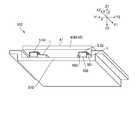
- FIG. 1is a perspective view of an input device 100 according to a first embodiment of the present invention as viewed from the side where the actuator 1 is disposed.
- the input device 100includes an input unit 4 having a touch panel 40, and an actuator 1 fixed to the input unit 4 from the other side Z2 in the Z direction and outputting vibration to the input unit 4. , And a connector 5 for connecting the input unit 4 to a frame or the like of the device.
- the actuator 1is fixed at the center of the surface of the other side Z2 in the Z direction of one input unit 4 via the reinforcing plate 47.
- the input unit 4has a display panel 45 which is integrated with the touch panel 40 so as to overlap on the other side Z2 in the Z direction, and the display panel 45 is a direct-view type such as a liquid crystal display panel or an organic electroluminescence display panel It is a display panel.
- the display panel 45displays various information in a region overlapping with the input surface 41 of the touch panel 40 and displays various switches and the like. Therefore, the user can input information by touching the portion of the input surface 41 of the touch panel 40 where the switch is displayed by the display panel 45, and the input result is the upper control unit (shown in FIG. Output).
- the input unit 4, the touch panel 40, and the display panel 45have a rectangular planar shape when viewed from the Z direction.
- the actuator 1outputs the vibration in the X direction along the input surface 41 to the input unit 4 under the control of the upper control unit, as described later with reference to FIGS. 2, 3 and 4.
- the actuator 1inputs the vibration in the X direction as an input unit Output to 4. Therefore, the input unit 4 transmits the vibration to the user's fingertip via the input surface 41. Therefore, the user can sense that the switch operation has been performed as a sense of touch.
- the actuator 1has a rectangular parallelepiped shape.
- the connector 5includes four connecting members 50 provided on each of the four corner portions of the input unit 4.
- Each of the four connecting members 50has a first plate portion 501 whose thickness direction is oriented in the Z direction, a second plate portion 502 whose thickness direction is oriented in the X direction, a first plate portion 501, and a second plate portion.
- the first plate portion 501is fixed to the surface of the other side Z2 in the Z direction of the input unit 4 via a reinforcing plate 48 by a screw, an adhesive or the like.
- two connecting members 50 located on one side X1 in the X directionrespectively have a second plate portion 502 mounted on the frame 200 of the device from the other side X2 in the X direction
- the second plate portion 502is fixed to the frame (not shown) of the device from one side X1 in the X direction by a screw, an adhesive or the like. It is done.
- the thickness direction of the third plate portion 503 of each of the four connecting members 50is in the X direction.
- the third plate portion 503functions as a plate spring portion which elastically deforms in the X direction following the input unit 4.
- FIG. 2is a perspective view showing a configuration example of the actuator 1 shown in FIG.
- FIG. 3is a YZ sectional view of the actuator 1 shown in FIG.
- FIG. 4is an XZ sectional view of the actuator 1 shown in FIG.
- the actuator 1has a rectangular parallelepiped shape as a whole, and the support 2 and the movable body 3 movably supported by the support 2 and the movable body And a drive circuit 6 for moving the support 3 relative to the support 2, and the drive circuit 6 vibrates the movable body 3 in the X direction.
- the support 2includes a cover 11 and a holder 60.
- the cover 11is a first cover member 16 covered from the one side Z1 in the Z direction with respect to the holder 60, and the cover 11 with the Z direction with respect to the holder 60.
- a second cover member 17covered from the other side Z2.
- the first cover member 16is a rectangular first end plate portion 160, and side plate portions 161, 162, 163, 164 that are bent from the end portions corresponding to the sides of the first end plate portion 160 to the other side Z2 in the Z direction.
- the second cover member 17is a rectangular second end plate portion 170, and side plate portions 171, 172, 173, and 174 bent from one end corresponding to each side of the second end plate portion 170 to one Z direction Z1.
- the side plate portions of the first cover member 16 and the second cover member 17are connected to each other with the holder 60 interposed therebetween.
- the drive circuit 6has a coil 7 and a magnet 8 opposed to the coil 7 in the Z direction.
- the coil 7is an oval cored air core coil in which the long side 701 (effective portion) extends in the Y direction.
- the coil 7is held by the holder 60 and provided on the side of the support 2.
- the magnet 8is provided on the movable body 3 side.
- the holder 60has side plate portions 61 and 62 opposed in the X direction and side plate portions 63 and 64 opposed in the Y direction, and both ends in the Y direction are connected to the side plate portions 63 and 64 inside
- an elongated coil holding portion 650whose longitudinal direction extends in the Y direction is formed, and the coil 7 is disposed in the coil holding portion 650.
- the coil holding portion 650is a through hole.
- receiving portions 631, 641 projecting from the side plate portions 63, 64 on the other side Z2 in the Z direction with respect to the plate portion 65are formed on both ends of the coil holding portion 650 in the Y direction. .
- the coil 7is attached to the coil holding portion 650, the short sides 702 (ineffective portions) located at both ends in the Y direction in the coil 7 are supported by the receiving portions 631 and 641. In this state, the coil 7 is fixed to the coil holding portion 650 by an adhesive or the like.
- the central portion of the side plate portion 63is a thin plate portion, and a recess 635 is formed on the outer surface side.
- the wiring substrate 18is fixed to the recess 635 by a method such as adhesion.
- a rectangular hole 184is formed in the wiring board 18, and two holes 634 are formed in the side plate portion 63 at positions overlapping the holes 184.
- the wiring board 18is exposed through the opening 163 a formed in the side plate portion 163 of the first cover member 16 and the opening 173 a formed in the side plate portion 173 of the second cover member 17. In the wiring board 18 configured in this way, the winding start end and the winding end end of the coil 7 are respectively drawn out through the holes 634 and the holes 184 and connected to the conductive pattern 185.
- the movable body 3includes a first yoke 86 provided with a main body portion 860 opposed to the coil 7 on one side Z1 in the Z direction, and a main body portion 870 opposed to the coil 7 on the other side Z2 in the Z direction. And a second yoke 87.
- the magnet 8is held by at least one of the surface of the main body 860 of the first yoke 86 facing the coil 7 and the surface of the main body 870 of the second yoke 87 opposite the coil 7 so as to face the coil 7 in the Z direction. doing.
- the first magnet 81is fixed to the surface of the main body 860 of the first yoke 86 facing the coil 7 by a method such as adhesion, and the coil 7 of the main body 870 of the second yoke 87.
- a second magnet 82 fixed to the opposite surface by a method such as adhesionis provided.
- the first magnet 81faces the long side 701 of the coil 7 on one side Z1 in the Z direction
- the second magnet 82faces the long side 701 of the coil 7 on the other side Z2 in the Z direction
- the first magnet 81 and the second magnet 82are respectively polarized and magnetized in the X direction, and the surface of the first magnet 81 facing the coil 7 and the surface of the second magnet 82 facing the coil 7 have different poles. It is magnetized.
- the first yoke 86has two first connection plate portions 861 extending from both ends of the main body portion 860 toward the other side Z2 in the Z direction, and the second yoke 87 extends from both ends of the main body portion 870.
- a second connection plate portion 871 extending toward the one side Z1 in the Z direction and overlapping the first connection plate portion 861is provided.
- the end portions of the first connection plate portion 861 and the second connection plate portion 871are connected by welding or the like.
- An elastic or visco-elastic connector 9is disposed between the movable body 3 and the support 2, and the connector 9 is in contact with both the movable body 3 and the support 2.
- a first viscoelasticityin which a main body portion 860 of the first yoke 86 of the movable body 3 and the first end plate portion 160 of the first cover member 16 are pinched in the Z direction as the connection body 9.
- the movable body 3is supported by the support 2 via the connector 9 (the first viscoelastic member 91 and the second viscoelastic member 92).
- the actuator 1configured as described above, when an alternating current is applied to the coil 7, the movable body 3 vibrates in the X direction, so the center of gravity of the actuator 1 changes in the X direction. Therefore, the actuator 1 can output vibration in the X direction.
- the first visco-elastic member 91 and the second visco-elastic member 92follow the movement of the movable body 3 to be deformed in the shear direction, and appropriately suppress the resonance when the movable body 3 is driven. Therefore, in the actuator 1, the resonance peak is broad in a wide frequency band.
- the visco-elasticityis a property in which both viscosity and elasticity are combined, and is a property which can be remarkably seen in high-molecular substances such as plastics and rubbers. Therefore, various gel members can be used as the first viscoelastic member 91 and the second viscoelastic member 92.
- first viscoelastic member 91 and the second viscoelastic member 92natural rubber, diene rubber (for example, styrene butadiene rubber, isoprene rubber, butadiene rubber), chloroprene rubber, acrylonitrile butadiene rubber, etc., non-diene
- diene rubberfor example, styrene butadiene rubber, isoprene rubber, butadiene rubber
- chloroprene rubberacrylonitrile butadiene rubber, etc.
- non-dieneVarious rubber materials such as a base rubber (eg, butyl rubber, ethylene / propylene rubber, ethylene / propylene / diene rubber, urethane rubber, silicone rubber, fluororubber, etc.), thermoplastic elastomers and the like and modified materials thereof may be used.
- a silicone gel having a penetration of 10 degrees to 110 degreesis used as the first viscoelastic member 91 and the second viscoelastic member 92.
- the penetration degreeis defined in JIS-K-2207 and JIS-K-2220, and the smaller the value, the harder it is.
- the first viscoelastic member 91 and the second viscoelastic member 92have linear or non-linear expansion and contraction characteristics depending on the expansion and contraction direction. For example, when the first viscoelastic member 91 and the second viscoelastic member 92 are pressed in the thickness direction (axial direction) and compressed and deformed, a component (spring coefficient) that is more nonlinear than a linear component (spring coefficient) ) Has large stretch characteristics. On the other hand, when it is pulled and extended in the thickness direction (axial direction), it has an expansion and contraction characteristic in which a linear component (spring coefficient) is larger than a non-linear component (spring coefficient).
- first visco-elastic member 91 and the second visco-elastic member 92are deformed in the direction (shearing direction) intersecting with the thickness direction (axial direction) as in the present embodiment, even if they move in any direction, Since the deformation is in the direction in which it is pulled and extends, it has a deformation characteristic in which a linear component (spring coefficient) is larger than a non-linear component (spring coefficient). Therefore, in the first viscoelastic member 91 and the second viscoelastic member 92, the spring force in the movement direction becomes constant.
- the connector 5constitutes a vibration system that uses the input unit 4 and the actuator 1 as a mass
- the vibration system using the spring property of the third plate portion 503 of the connection member 50is a plurality of vibration systems. It has a resonant frequency.
- a vibration system utilizing the spring property of the connector 5has resonant frequencies at 100 Hz, 200 Hz, and 300 Hz.
- the actuator 1vibrates the movable body 3 with a broad resonance peak in a frequency band (for example, 50 Hz to 400 Hz) including a plurality of resonance frequencies (100 Hz, 200 Hz and 300 Hz) of the connector 5.
- a frequency bandfor example, 50 Hz to 400 Hz
- resonance frequencies100 Hz, 200 Hz and 300 Hz
- the upper control unitdrives the actuator 1 at a frequency equal to one of a plurality of resonance frequencies (100 Hz, 200 Hz, 300 Hz) of the vibration system utilizing the spring property of the connector 5. And causes the actuator 1 to output an oscillation having a frequency equal to one of the resonance frequencies (100 Hz, 200 Hz, 300 Hz) of the connector 5.
- the upper control unitchanges the drive condition of the actuator 1 according to the operation content of the user on the touch panel 40, and causes the input unit 4 to output the vibration of the frequency according to the operation content of the user.
- the actuator 1when the user touches a specific switch, the actuator 1 outputs vibration with a frequency of 100 Hz to the input unit 4, and when another user touches the switch, the actuator 1 inputs a vibration with a frequency of 200 Hz.
- the switch 4is touched and another switch is touched, a vibration with a frequency of 300 Hz is outputted to the input unit 4. Therefore, the user feels the vibration of the frequency corresponding to the operation.
- the connector 5has a spring property that forms a vibration system having a plurality of resonance frequencies with the input unit 4 and the actuator 1 as a mass. Vibrates the movable body at a frequency equal to one of the plurality of resonance frequencies. For this reason, since the vibration of the actuator 1 can be transmitted to the user's fingertip in a resonated state using the spring property of the connector 5, the user can feel strong vibration. Further, in the actuator 1, the first viscoelastic member 91 and the second viscoelastic member 92 are used as the connection body 9, and the resonance peak when the movable body 3 is vibrated in the actuator 1 by the damper action is It is broad in a wide frequency band.
- the actuator 1can output the vibration of the frequency corresponding to the plurality of resonance frequencies of the connector 5 to the input unit 4.
- the actuator 1vibrates the movable body 3 with a broad resonance peak in a frequency band including a plurality of resonance frequencies of the connector 5, even when the apparatus is configured using input units having different masses,
- the same actuator 1can be used in common since it can be vibrated strongly at the resonance frequency. Therefore, it is not necessary to manufacture a plurality of types of actuators 1, and it is possible to manufacture the actuators 1 inexpensively by the mass production effect by the same model.
- the input unit 4is strongly vibrated at the changed resonance frequency by vibrating the actuator 1 at the changed resonance frequency. It can be done. Therefore, the input unit 4 can be vibrated at an arbitrary frequency that the user wants to experience, and the user can feel it.
- FIG. 5is a perspective view of the connecting member 50 used in the input device 100 according to the second embodiment of the present invention.
- FIG. 6is a perspective view of the input device 100 according to the second embodiment of the present invention as viewed from the side where the actuator 1 is disposed.
- the same reference numeralsare given to the common portions and the description thereof will be omitted.
- the connecting member 50 used for the connecting body 5has the first plate portion 501 with the plate thickness direction oriented in the Z direction and the second plate portion 502 with the plate thickness direction oriented in the X direction. It was on the other hand, in the present embodiment, as shown in FIG. 5, the connecting member 50 used for the connecting member 5 has the first plate portion 501 with the thickness direction turned in the Z direction, and the thickness direction in the Z direction. A second plate portion 502 facing the first plate portion 501, and a third plate portion 503 curved so as to connect the first plate portion 501 and the second plate portion 502, The plate portion 503 is a plate spring portion which can be elastically deformed in the X direction.
- the first plate portion 501is fixed to the surface of the other side Z2 in the Z direction of the input unit 4 with a screw or an adhesive.
- a screw or an adhesiveare fixed to the frame 210 of the device from one side Z1 in the Z direction by screws, adhesives or the like.
- the connecting members 50are provided at four places where the four corner portions of the input unit 4 and the four corner portions of the frame 210 overlap.
- FIG. 7is a perspective view of the input device 100 according to the third embodiment of the present invention as viewed from the side where the actuator 1 is disposed.
- the same reference numeralsare given to the common portions and the description thereof will be omitted.
- the input device 100includes the input unit 4 having the touch panel 40 and the other side Z2 in the Z direction of the input unit 4. It has the actuator 1 which is fixed and outputs a vibration to the input unit 4, and the connection body 5 for connecting the input unit 4 to the frame etc. of an apparatus.
- the drive circuit 6 described with reference to FIGS. 2, 3 and 4vibrates the movable body 3 in the X direction and the Y direction. Therefore, the actuator 1 transmits the vibration in the X direction and the Y direction to the input unit 4. Therefore, the user can experience the signal combining the vibration in the X direction, the vibration in the Y direction, and the vibration in the X direction and the vibration in the Y direction.
- the connector 5has a spring property that can be elastically deformed in the X direction and the Y direction.
- the connecting member 5includes a first connecting member 51 connected to the input unit 4 and a second connecting member 52 connected to the side opposite to the input unit 4 with respect to the first connecting member 51.
- the second connecting member 52is connected to the frames 220 and 230 of the device.
- the first connection member 51has a springability that can be elastically deformed in the X direction
- the second connection member 52has a springability that can be elastically deformed in the Y direction.
- the first connecting member 51is the connecting member 50 described with reference to FIG. 5, and the first plate portion 501 with the thickness direction facing in the Z direction and the thickness direction in the Z direction.
- a third plate portion 503which is curved so as to connect the first plate portion 501 and the second plate portion 502, and the third plate portion 503 is opposed to the first plate portion 501.
- the portion 503is a leaf spring portion that can be elastically deformed in the X direction.
- the second plate portion 502is connected to the second connection member 52.
- the second connecting member 52has a structure in which two plates are stacked, and a support plate portion 521 facing the input unit 4 on the other side Z2 in the Z direction, and both end portions of the support plate portion 521 in the Y direction And two connecting plate portions 522 which are bent to the other side Z2 in the Z direction.
- the second plate portion 502 of the first connecting member 51is connected to the support plate portion 521.
- the two connecting plate portions 522 of the second connecting member 52are respectively connected to the frames 220 and 230 of the device by a screw, an adhesive or the like. In this state, the two connection plate portions 522 are both leaf spring portions that can be elastically deformed in the Y direction.
- the connector 5has a spring property that can be elastically deformed in the X direction and a spring property that can be elastically deformed in the Y direction.
- the vibration system having the actuator 1 as a masshas resonance frequencies at 100 Hz, 200 Hz, and 300 Hz in each of the vibration in the X direction and the vibration in the Y direction. Therefore, the actuator 1 outputs vibration in the X direction at a frequency of 100 Hz, 200 Hz or 300 Hz, and outputs vibration in the Y direction at a frequency of 100 Hz, 200 Hz or 300 Hz. Therefore, it is possible to cause the user to strongly feel various vibrations according to the operation content of the touch panel 40 by the user.
- FIG. 8is a perspective view of the input device 100 according to the fourth embodiment of the present invention as viewed from the side where the actuator 1 is disposed.
- the same reference numeralsare given to the common portions and the description thereof will be omitted.
- the input device 100includes the input unit 4 including the touch panel 40 and the other side Z2 of the input unit 4 in the Z direction. And an actuator 1 for outputting the vibration to the input unit 4 and a connector 5 for connecting the input unit 4 to the frame 210 of the apparatus.
- a damper member 58is provided between the input unit 4 and the frame 210 of the device.
- a visco-elastic member 59such as silicone gel is used.
- the other configurationis the same as that of the second embodiment.
- the vibration of the input unit 4can be damped by the damper member 58 (viscoelastic member 59), the vibration of the input unit 4 can be smoothly stopped.
- the configuration in which the damper member 58 (viscoelastic member 59) is provided between the input unit 4 and the deviceis not limited to the second embodiment, and may be applied to the input device 100 according to the first and third embodiments.
- FIG. 9is a perspective view of the connecting member 50 used in the input device 100 according to the fifth embodiment of the present invention.
- the same reference numeralsare given to the common portions and the description thereof will be omitted.
- the spring constant of the third plate portion 503is corrected to optimize the resonance frequency of the vibration system utilizing the spring property of the connecting member 5, as shown in FIG.
- the aspect which formed the slit 503a in the 3rd board part 503may be employ
- a notchmay be provided in the side plate portion of the third plate portion 503 to optimize the resonance frequency.
- the damper member 58may be used, but after the drive circuit 6 vibrates the movable body 3 to vibrate the input unit 4,
- the drive circuit 6may adopt a mode in which the movable body 3 vibrates in the opposite phase to the vibration of the input unit 4. According to such a configuration, the vibration of the input unit 4 Can be attenuated efficiently, so that the vibration of the input unit 4 can be smoothly stopped.
- connection body 9 of the actuator 1adopts an aspect in which the resonance frequency of the vibration system having the movable body 3 as a mass deviates from the resonance frequency of the vibration system having the input unit 4 and the actuator 1 as a mass. preferable.
Landscapes
- Engineering & Computer Science (AREA)
- General Engineering & Computer Science (AREA)
- Physics & Mathematics (AREA)
- Theoretical Computer Science (AREA)
- Power Engineering (AREA)
- Human Computer Interaction (AREA)
- General Physics & Mathematics (AREA)
- Electromagnetism (AREA)
- Mechanical Engineering (AREA)
- Apparatuses For Generation Of Mechanical Vibrations (AREA)
- Reciprocating, Oscillating Or Vibrating Motors (AREA)
Abstract
Description
Translated fromJapanese本発明は、タッチパネルの入力面を振動させることのできる入力装置に関するものである。The present invention relates to an input device capable of vibrating an input surface of a touch panel.
タッチパネルを用いた入力装置は、機械的スイッチを用いた機械式の入力装置と違って、ソフトウェアによって入力画面を自由に構成できるという利点がある一方、入力操作を行った感触を操作者に与えることができない。そこで、入力操作に伴って、入力面を振動させる技術が提案されている(特許文献1参照)。Unlike mechanical input devices using mechanical switches, an input device using a touch panel has the advantage that the input screen can be freely configured by software, while giving the operator the feeling of performing an input operation. I can not Then, the technique which vibrates an input surface is proposed with input operation (refer patent document 1).
特許文献1に記載の技術では、タッチパネルがサスペンションを介してハウジングに支持された構成が記載されている。かかる入力装置において、アクチュエータで発生した第1周波数の振動については、サスペンションに設けた発泡部材によってタッチパネルとハウジングとを分離することによりタッチパネルのみを振動させ、利用者の指先に振動を伝達する。これに対して、アクチュエータで発生した第2周波数の振動については、発泡部材をハウジングに伝達して、ハウジングを持つ利用者の手に伝達する。The technology described in
特許文献1に記載の入力装置では、アクチュエータで発生した振動のみを利用するため、振動の大きさ(振幅、加速度)が小さいという問題点がある。The input device disclosed in
以上の問題点に鑑みて、本発明の課題は、利用者に振動を強く伝達することができる入力装置を提供することにある。In view of the above problems, it is an object of the present invention to provide an input device capable of strongly transmitting vibration to a user.
上記問題を解決するために、本発明に係る入力装置は、タッチパネルを備えた入力ユニットと、支持体、弾性または粘弾性を備えた接続体を介して前記支持体に支持された可動体、および前記可動体を振動させる駆動回路を備え、前記入力ユニットに固定されて前記可動体の振動を前記入力ユニットに出力するアクチュエータと、前記入力ユニットを機器に連結するための連結体と、を有し、前記連結体は、前記入力ユニットおよび前記アクチュエータを質量にして複数の共振周波数を有する振動系を構成するバネ性を有し、前記アクチュエータは、前記複数の共振周波数のいずれかと等しい周波数で前記可動体を振動させることを特徴とする。In order to solve the above problems, an input device according to the present invention includes an input unit having a touch panel, a support, a movable body supported by the support via a connector having elasticity or viscoelasticity, and It has a drive circuit for vibrating the movable body, and has an actuator fixed to the input unit to output the vibration of the movable body to the input unit, and a connector for connecting the input unit to a device. The coupling body has a spring property which forms a vibration system having a plurality of resonance frequencies with the input unit and the actuator as a mass, and the actuator is movable at a frequency equal to any of the plurality of resonance frequencies. It is characterized by vibrating the body.
本発明において、入力ユニットにはアクチュエータが固定されているため、アクチュエータにおいて、駆動回路が可動体を振動させると、可動体の振動が入力ユニットに伝達される。従って、入力ユニットに対する操作に対応した振動を利用者の指先に伝達することができる。ここで、連結体は、入力ユニットおよびアクチュエータを質量にして複数の共振周波数を有する振動系を構成するバネ性を有しており、アクチュエータは、複数の共振周波数のいずれかと等しい周波数で可動体を振動させる。このため、アクチュエータの振動を連結体のバネ性を利用して共振させた状態で利用者の指先に伝達することができるので、利用者に強い振動を体感させることができる。In the present invention, since the actuator is fixed to the input unit, when the drive circuit vibrates the movable body in the actuator, the vibration of the movable body is transmitted to the input unit. Therefore, the vibration corresponding to the operation on the input unit can be transmitted to the user's fingertip. Here, the connector has a spring property that forms a vibration system having a plurality of resonance frequencies with the input unit and the actuator as a mass, and the actuator has a movable body at a frequency equal to any of the plurality of resonance frequencies. Vibrate. Therefore, since the vibration of the actuator can be transmitted to the user's fingertip in a resonated state using the spring property of the coupling body, the user can feel strong vibration.
本発明において、前記アクチュエータは、前記複数の共振周波数を含む周波数帯域にブロードな共振ピークをもって前記可動体を振動させる態様を採用することができる。かかる態様によれば、質量の異なる入力ユニットを用いて装置を構成した場合でも、その構成における共振周波数で強く振動させることができるため、同一のアクチュエータを共通で使用することができる。従って、複数種類のアクチュエータを製作する必要がなく、同一機種による量産効果で安価にアクチュエータを製作することが可能である。また、同一の入力装置を用いながら、連結体のバネ定数を変更した場合には、変更後の共振周波数でアクチュエータを振動させることにより、変更後の共振周波数で入力ユニットを強く振動させることができる。従って、利用者に体感させたい任意の周波数で入力ユニットを振動させ、利用者に体感させることができる。In the present invention, the actuator may adopt an aspect of vibrating the movable body with a broad resonance peak in a frequency band including the plurality of resonance frequencies. According to this aspect, even when the apparatus is configured using input units having different masses, the same actuator can be used in common since the apparatus can be strongly vibrated at the resonance frequency in the configuration. Therefore, it is not necessary to manufacture a plurality of types of actuators, and it is possible to manufacture the actuators inexpensively by mass production effect by the same model. When the spring constant of the connector is changed while using the same input device, the input unit can be strongly vibrated at the changed resonance frequency by vibrating the actuator at the changed resonance frequency. . Therefore, the input unit can be vibrated at an arbitrary frequency that the user wants to experience, and can be felt by the user.
本発明において、前記アクチュエータは、前記タッチパネルの入力面に沿う第1方向に前記可動体を振動させ、前記連結体は、前記第1方向に弾性変形可能なバネ性を有している態様を採用することができる。例えば、前記連結体は、前記第1方向に弾性変形可能な板バネ部を有している態様を採用することができる。In the aspect of the invention, the actuator vibrates the movable body in a first direction along the input surface of the touch panel, and the connector has a spring property that can be elastically deformed in the first direction. can do. For example, the connection body may adopt an aspect in which a plate spring portion elastically deformable in the first direction is provided.
本発明において、前記アクチュエータは、さらに、前記入力ユニットの入力面に沿って前記第1方向に交差する第2方向に前記可動体を振動させ、前記連結体は、前記第1方向に弾性変形可能なバネ性、および前記第2方向に弾性変形可能なバネ性を有している態様を採用することができる。この場合、前記連結体は、前記入力ユニットに接続された第1連結部材と、前記第1連結部材に対して前記入力ユニットと反対側に接続された第2連結部材と、を備え、前記第1連結部材は、前記第1方向に弾性変形可能なバネ性を有し、前記第2連結部材は、前記第2方向に弾性変形可能なバネ性を有している態様を採用することができる。例えば、前記第1連結部材は、前記第1方向に弾性変形可能な板バネ部を有し、前記第2連結部材は、前記第2方向に弾性変形可能な板バネ部を有している態様を採用することができる。In the present invention, the actuator further vibrates the movable body in a second direction crossing the first direction along the input surface of the input unit, and the coupling body is elastically deformable in the first direction. It is possible to adopt an aspect having a good spring property and a spring property that can be elastically deformed in the second direction. In this case, the connection body includes a first connection member connected to the input unit, and a second connection member connected to the side opposite to the input unit with respect to the first connection member, (1) The connecting member may have an elasticity capable of elastically deforming in the first direction, and the second connecting member may adopt an aspect having an elasticity capable of elastic deformation in the second direction. . For example, the first connection member has a plate spring portion that can be elastically deformed in the first direction, and the second connection member has a plate spring portion that can be elastically deformed in the second direction. Can be adopted.
本発明において、前記接続体は、粘弾性部材である態様を採用することができる。かかる態様によれば、アクチュエータでは、可動体を振動させた際の共振ピークが広い周波数帯域においてブロードである。従って、アクチュエータは、連結体の複数の共振周波数に対応する周波数の振動を入力ユニットに出力することができる。In the present invention, the connecting member may adopt an aspect of being a visco-elastic member. According to this aspect, in the actuator, the resonance peak when vibrating the movable body is broad in a wide frequency band. Therefore, the actuator can output vibration of a frequency corresponding to a plurality of resonant frequencies of the coupling body to the input unit.
本発明において、前記入力ユニットと前記機器との間にダンパー部材が設けられる態様を採用することができる。本発明において、前記ダンパー部材は、粘弾性部材である態様を採用することができる。かかる態様によれば、入力ユニットの振動がダンパー部材によって減衰するので、入力ユニットの振動をスムーズに停止させることができる。In the present invention, an aspect in which a damper member is provided between the input unit and the device can be adopted. In the present invention, an aspect in which the damper member is a visco-elastic member can be adopted. According to this aspect, since the vibration of the input unit is damped by the damper member, the vibration of the input unit can be smoothly stopped.
本発明において、前記駆動回路が前記可動体を振動させて前記入力ユニットを振動させた後、前記入力ユニットの振動を停止させる際には、前記駆動回路が前記可動体を前記入力ユニットの振動と逆位相に振動させる態様を採用することができる。かかる態様によれば、入力ユニットの振動を効率よく減衰させることができるので、入力ユニットの振動をスムーズに停止させることができる。In the present invention, when the drive circuit vibrates the movable body to vibrate the input unit and then stops the vibration of the input unit, the drive circuit causes the movable body to vibrate in the input unit. It is possible to adopt an aspect of oscillating in the opposite phase. According to this aspect, since the vibration of the input unit can be efficiently damped, the vibration of the input unit can be smoothly stopped.
本発明において、前記入力ユニットは、前記タッチパネルと一体化された表示パネルを有している態様を採用することができる。In the present invention, the input unit may adopt an aspect having a display panel integrated with the touch panel.
本発明において、入力ユニットにはアクチュエータが固定されているため、アクチュエータにおいて、駆動回路が可動体を振動させると、可動体の振動が入力ユニットに伝達される。従って、入力ユニットに対する操作に対応した振動を利用者の指先に伝達することができる。ここで、連結体は、入力ユニットおよびアクチュエータを質量にして複数の共振周波数を有する振動系を構成するバネ性を有しており、アクチュエータは、複数の共振周波数のいずれかと等しい周波数で可動体を振動させる。このため、アクチュエータの振動を連結体のバネ性を利用して共振させた状態で利用者の指先に伝達することができるので、利用者に強い振動を体感させることができる。また、アクチュエータが、連結体の複数の共振周波数を含む周波数帯域にブロードな共振ピークをもって可動体を振動させる場合には、質量の異なる入力ユニットを用いて装置を構成した場合でも、その構成における共振周波数で強く振動させることができるため、同一のアクチュエータを共通で使用することができる。従って、複数種類のアクチュエータを製作する必要がなく、同一機種による量産効果で安価にアクチュエータを製作することが可能である。また、同一の入力装置を用いながら、連結体のバネ定数を変更した場合には、変更後の共振周波数でアクチュエータを振動させることにより、変更後の共振周波数で入力ユニットを強く振動させることができる。従って、利用者に体感させたい任意の周波数で入力ユニットを振動させ、利用者に体感させることができる。In the present invention, since the actuator is fixed to the input unit, when the drive circuit vibrates the movable body in the actuator, the vibration of the movable body is transmitted to the input unit. Therefore, the vibration corresponding to the operation on the input unit can be transmitted to the user's fingertip. Here, the connector has a spring property that forms a vibration system having a plurality of resonance frequencies with the input unit and the actuator as a mass, and the actuator has a movable body at a frequency equal to any of the plurality of resonance frequencies. Vibrate. Therefore, since the vibration of the actuator can be transmitted to the user's fingertip in a resonated state using the spring property of the coupling body, the user can feel strong vibration. In addition, when the actuator vibrates the movable body with a broad resonance peak in a frequency band including a plurality of resonance frequencies of the connector, even when the apparatus is configured using an input unit of different mass, the resonance in that configuration. The same actuator can be used in common since it can be vibrated strongly at frequency. Therefore, it is not necessary to manufacture a plurality of types of actuators, and it is possible to manufacture the actuators inexpensively by mass production effect by the same model. When the spring constant of the connector is changed while using the same input device, the input unit can be strongly vibrated at the changed resonance frequency by vibrating the actuator at the changed resonance frequency. . Therefore, the input unit can be vibrated at an arbitrary frequency that the user wants to experience, and can be felt by the user.
図面を参照して、本発明の実施形態を説明する。なお、以下の説明において、互いに交差する3方向をX方向(第1方向)、Y方向(第2方向)およびZ方向(第3方向)とし、X方向の一方側にX1を付し、X方向の他方側にX2を付し、Y方向の一方側にY1を付し、Y方向の他方側にY2を付し、Z方向の一方側にZ1を付し、Z方向の他方側にZ2を付して説明する。また、X方向およびY方向は、タッチパネル40の入力面41に沿う面内方向であり、Z方向は、入力面41に対する法線方向である。また、以下の説明で参照する図においては、各部材を図面上で認識可能な程度の大きさとするため、各層や各部材毎に縮尺を異ならしめてある。Embodiments of the present invention will be described with reference to the drawings. In the following description, three directions intersecting with each other are taken as an X direction (first direction), a Y direction (second direction) and a Z direction (third direction), and X1 is attached to one side in the X direction. X2 on one side of the direction, Y1 on one side in the Y direction, Y2 on the other side in the Y direction, Z1 on one side in the Z direction, Z2 on the other side in the Z direction The explanation is attached. Further, the X direction and the Y direction are in-plane directions along the
[実施形態1]
(全体構成)
図1は、本発明の実施形態1に係る入力装置100をアクチュエータ1が配置されている側からみた斜視図である。図1に示すように、本形態の入力装置100は、タッチパネル40を備えた入力ユニット4と、入力ユニット4にZ方向の他方側Z2から固定されて振動を入力ユニット4に出力するアクチュエータ1と、入力ユニット4を機器のフレーム等に連結するための連結体5とを有している。本形態において、アクチュエータ1は、1台の入力ユニット4のZ方向の他方側Z2の面の中央に補強板47を介して固定されている。
(overall structure)
FIG. 1 is a perspective view of an
入力ユニット4は、タッチパネル40に対してZ方向の他方側Z2に重なって一体化された表示パネル45を有しており、表示パネル45は、液晶表示パネルや有機エレクトロルミネッセンス表示パネル等の直視型表示パネルである。表示パネル45は、タッチパネル40の入力面41に対して重なる領域で、各種情報を表示するとともに、各種スイッチ等を表示する。従って、利用者は、タッチパネル40の入力面41のうち、表示パネル45によってスイッチが表示された部分に指先を触れることによって情報の入力を行うことができ、入力結果は上位の制御部(図示せず)に出力される。本形態において、入力ユニット4、タッチパネル40、および表示パネル45は、Z方向からみたとき、四角形の平面形状を有している。The input unit 4 has a
アクチュエータ1は、図2、図3および図4を参照して後述するように、上位の制御部の制御の下、入力面41に沿ったX方向の振動を入力ユニット4に出力する。例えば、利用者の指先が、タッチパネル40の入力面41のうち、表示パネル45によってスイッチが表示されている部分に触れて情報の入力を行った際、アクチュエータ1は、X方向の振動を入力ユニット4に出力する。従って、入力ユニット4は、入力面41を介して利用者の指先に振動を伝達する。それ故、利用者は、スイッチ操作を行ったことを触覚として体感することができる。本形態において、アクチュエータ1は直方体形状を有している。The
本形態において、連結体5は、入力ユニット4の4つの角部分の各々に設けられた4つの連結部材50からなる。4つの連結部材50は各々、Z方向に板厚方向を向けた第1板部501と、X方向に板厚方向を向けた第2板部502と、第1板部501と第2板部502とを繋ぐ第3板部503とを有している。4つの連結部材50は各々、第1板部501が入力ユニット4のZ方向の他方側Z2の面に補強板48を介してネジや接着剤等により固定されている。また、4つの連結部材50のうち、X方向の一方側X1に位置する2つの連結部材50は各々、第2板部502が機器のフレーム200にX方向の他方側X2からネジや接着剤等により固定され、X方向の他方側X2に位置する2つの連結部材50は各々、第2板部502が機器のフレーム(図示せず)にX方向の一方側X1からネジや接着剤等により固定されている。この状態で、4つの連結部材50は各々、第3板部503の板厚方向がX方向に向いている。第3板部503は、入力ユニット4に追従してX方向に弾性変形する板バネ部として機能する。In the present embodiment, the
(アクチュエータ1の構成例)
図2は、図1に示すアクチュエータ1の構成例を示す斜視図である。図3は、図2に示すアクチュエータ1のYZ断面図である。図4は、図2に示すアクチュエータ1のXZ断面図である。(Configuration example of actuator 1)
FIG. 2 is a perspective view showing a configuration example of the
図2、図3および図4に示すように、アクチュエータ1は、全体として、直方体形状を有しており、支持体2と、支持体2に移動可能に支持された可動体3と、可動体3を支持体2に対して相対移動させる駆動回路6とを有しており、駆動回路6は、可動体3をX方向に振動させる。As shown in FIG. 2, FIG. 3 and FIG. 4, the
支持体2は、カバー11とホルダ60とを有しており、カバー11は、ホルダ60に対してZ方向の一方側Z1から被さった第1カバー部材16と、ホルダ60に対してZ方向の他方側Z2から被さった第2カバー部材17とを有している。第1カバー部材16は、四角形の第1端板部160と、第1端板部160の各辺に相当する端部からZ方向の他方側Z2に折れ曲がった側板部161、162、163、164とを有している。第2カバー部材17は、四角形の第2端板部170と、第2端板部170の各辺に相当する端部からZ方向の一方Z1に折れ曲がった側板部171、172、173、174とを有しており、第1カバー部材16と第2カバー部材17とは、ホルダ60を間に挟んだ状態で側板部同士が連結されている。The
駆動回路6は、コイル7と、コイル7に対してZ方向で対向する磁石8とを有している。本形態において、コイル7は、Y方向に長辺701(有効部分)が延在する長円形状の空芯コイルである。コイル7はホルダ60に保持されており、支持体2の側に設けられている。磁石8は、可動体3の側に設けられている。The
ホルダ60は、X方向で対向する側板部61、62と、Y方向で対向する側板部63、64とを有しており、内側には、Y方向の両端部が側板部63、64と繋がった板部65を有している、板部65には、Y方向に長方向が延在する長円状のコイル保持部650が形成されており、コイル保持部650にコイル7が配置されている。コイル保持部650は貫通穴である。但し、ホルダ60において、コイル保持部650のY方向の両端側には、板部65に対してZ方向の他方側Z2で側板部63、64から突出した受け部631、641が形成されている。従って、コイル保持部650にコイル7を装着すると、コイル7においてY方向の両端に位置する短辺702(無効部分)が受け部631、641に支持される。この状態で、コイル7は、接着剤等によってコイル保持部650に固定される。The
側板部63の中央部分は薄板部分になっており、外面側に凹部635が形成されている。凹部635には配線基板18が接着等の方法で固定されている。配線基板18には矩形の穴184が形成されており、側板部63において穴184と重なる位置には2つの穴634が形成されている。配線基板18には、ランドを備えた2つの導電パターン185が形成されている。配線基板18は、第1カバー部材16の側板部163に形成した開口部163a、および第2カバー部材17の側板部173に形成した開口部173aを介して露出した状態にある。このように構成した配線基板18においては、穴634および穴184を介してコイル7の巻き始めの端部および巻き終わりの端部を各々、外側に引き出して導電パターン185に接続される。The central portion of the
可動体3は、コイル7に対してZ方向の一方側Z1で対向する本体部分860を備えた第1ヨーク86と、コイル7に対してZ方向の他方側Z2で対向する本体部分870を備えた第2ヨーク87とを有している。磁石8は、第1ヨーク86の本体部分860のコイル7と対向する面、および第2ヨーク87の本体部分870のコイル7と対向する面の少なくとも一方に保持されてコイル7にZ方向で対向している。The
本形態では、磁石8として、第1ヨーク86の本体部分860のコイル7と対向する面に接着等の方法で固定された第1磁石81と、第2ヨーク87の本体部分870のコイル7と対向する面に接着等の方法で固定された第2磁石82とが設けられている。この状態で、第1磁石81は、コイル7の長辺701にZ方向の一方側Z1で対向し、第2磁石82は、コイル7の長辺701にZ方向の他方側Z2で対向している。第1磁石81および第2磁石82は各々、X方向で分極着磁されており、第1磁石81においてコイル7に対向する面と、第2磁石82においてコイル7と対向する面は異なる極に着磁されている。In this embodiment, as the magnet 8, the first magnet 81 is fixed to the surface of the
第1ヨーク86は、本体部分860の両端からZ方向の他方側Z2に向けて延在した2つの第1連結板部861を有しており、第2ヨーク87は、本体部分870の両端からZ方向の一方側Z1に向けて延在して第1連結板部861と重なる第2連結板部871とを有している。第1連結板部861と第2連結板部871とは端部同士が溶接等によって連結されている。The
可動体3と支持体2との間には、弾性または粘弾性を備えた接続体9が配置されており、接続体9は、可動体3および支持体2の双方に接している。本形態において、接続体9として、可動体3の第1ヨーク86の本体部分860と第1カバー部材16の第1端板部160とがZ方向で対向する部分に挟まれた第1粘弾性部材91と、可動体3の第2ヨーク87の本体部分870と第2カバー部材17の第2端板部170とがZ方向で対向する部分に挟まれた第2粘弾性部材92とが設けられている。その結果、可動体3は、接続体9(第1粘弾性部材91および第2粘弾性部材92)を介して支持体2に支持されている。An elastic or visco-elastic connector 9 is disposed between the
このように構成したアクチュエータ1において、コイル7に交流を印加すると、可動体3は、X方向に振動するため、アクチュエータ1における重心がX方向に変動する。このため、アクチュエータ1は、X方向の振動を出力することができる。その際、第1粘弾性部材91および第2粘弾性部材92は、可動体3の移動に追従してせん断方向に変形するとともに、可動体3を駆動した際の共振を適正に抑制する。このため、アクチュエータ1では、共振ピークが広い周波数帯域においてブロードである。In the
ここで、粘弾性とは、粘性と弾性の両方を合わせた性質のことであり、プラスチックやゴム等の高分子物質に顕著に見られる性質である。従って、第1粘弾性部材91および第2粘弾性部材92として、各種ゲル部材を用いることができる。また、第1粘弾性部材91および第2粘弾性部材92として、天然ゴム、ジエン系ゴム(例えば、スチレン・ブタジエンゴム、イソプレンゴム、ブタジエンゴム)、クロロプレンゴム、アクリロニトリル・ブタジエンゴム等)、非ジエン系ゴム(例えば、ブチルゴム、エチレン・プロピレンゴム、エチレン・プロピレン・ジエンゴム、ウレタンゴム、シリコーンゴム、フッ素ゴム等)、熱可塑性エラストマー等の各種ゴム材料及びそれらの変性材料を用いてもよい。本形態では、第1粘弾性部材91および第2粘弾性部材92として、針入度が10度から110度であるシリコーン系ゲルが用いられている。針入度とは、JIS-K-2207やJIS-K-2220で規定されており、この値が小さい程、硬いことを意味する。Here, the visco-elasticity is a property in which both viscosity and elasticity are combined, and is a property which can be remarkably seen in high-molecular substances such as plastics and rubbers. Therefore, various gel members can be used as the first viscoelastic member 91 and the second viscoelastic member 92. Further, as the first viscoelastic member 91 and the second viscoelastic member 92, natural rubber, diene rubber (for example, styrene butadiene rubber, isoprene rubber, butadiene rubber), chloroprene rubber, acrylonitrile butadiene rubber, etc., non-diene Various rubber materials such as a base rubber (eg, butyl rubber, ethylene / propylene rubber, ethylene / propylene / diene rubber, urethane rubber, silicone rubber, fluororubber, etc.), thermoplastic elastomers and the like and modified materials thereof may be used. In the present embodiment, a silicone gel having a penetration of 10 degrees to 110 degrees is used as the first viscoelastic member 91 and the second viscoelastic member 92. The penetration degree is defined in JIS-K-2207 and JIS-K-2220, and the smaller the value, the harder it is.
第1粘弾性部材91および第2粘弾性部材92は、その伸縮方向によって、線形あるいは非線形の伸縮特性を備える。例えば、第1粘弾性部材91および第2粘弾性部材92は、その厚さ方向(軸方向)に押圧されて圧縮変形する際は、線形の成分(バネ係数)よりも非線形の成分(バネ係数)が大きい伸縮特性を備える。これに対して、厚さ方向(軸方向)に引っ張られて伸びる場合は、非線形の成分(バネ係数)よりも線形の成分(バネ係数)が大きい伸縮特性を備える。The first viscoelastic member 91 and the second viscoelastic member 92 have linear or non-linear expansion and contraction characteristics depending on the expansion and contraction direction. For example, when the first viscoelastic member 91 and the second viscoelastic member 92 are pressed in the thickness direction (axial direction) and compressed and deformed, a component (spring coefficient) that is more nonlinear than a linear component (spring coefficient) ) Has large stretch characteristics. On the other hand, when it is pulled and extended in the thickness direction (axial direction), it has an expansion and contraction characteristic in which a linear component (spring coefficient) is larger than a non-linear component (spring coefficient).
一方、本形態のように、第1粘弾性部材91および第2粘弾性部材92が厚さ方向(軸方向)と交差する方向(せん断方向)に変形する場合、いずれの方向に動いても、引っ張られて伸びる方向の変形であるため、非線形の成分(バネ係数)よりも線形の成分(バネ係数)が大きい変形特性を持つ。従って、第1粘弾性部材91および第2粘弾性部材92では、運動方向によるバネ力が一定となる。それ故、本形態のように、第1粘弾性部材91および第2粘弾性部材92のせん断方向のバネ要素を用いることにより、入力信号に対する振動加速度の再現性を向上することができるので、微妙なニュアンスもって振動を実現することができる。On the other hand, when the first visco-elastic member 91 and the second visco-elastic member 92 are deformed in the direction (shearing direction) intersecting with the thickness direction (axial direction) as in the present embodiment, even if they move in any direction, Since the deformation is in the direction in which it is pulled and extends, it has a deformation characteristic in which a linear component (spring coefficient) is larger than a non-linear component (spring coefficient). Therefore, in the first viscoelastic member 91 and the second viscoelastic member 92, the spring force in the movement direction becomes constant. Therefore, as in the present embodiment, by using the spring elements in the shear direction of the first viscoelastic member 91 and the second viscoelastic member 92, it is possible to improve the reproducibility of the vibration acceleration with respect to the input signal. Vibration can be realized with a nuance.
(入力装置100の動作)
再び図1において、入力装置100において、アクチュエータ1がX方向の振動を入力ユニット4に出力し、入力ユニット4がX方向に振動した際、連結体5に用いた連結部材50の第3板部503が、入力ユニット4に追従してX方向に弾性変形する。従って、連結体5は、入力ユニット4およびアクチュエータ1を質量にした振動系を構成しており、本形態において、連結部材50の第3板部503のバネ性を利用した振動系は、複数の共振周波数を有している。例えば、連結体5のバネ性を利用した振動系は、100Hz、200Hz、300Hzに共振周波数を有している。これに対して、アクチュエータ1は、連結体5の複数の共振周波数(100Hz、200Hzおよび300Hz)を含む周波数帯域(例えば、50Hz~400Hz)にブロードな共振ピークをもって可動体3を振動させる。(Operation of input device 100)
In FIG. 1 again, in the
かかる構成に対応して、上位の制御部は、アクチュエータ1を駆動する際、連結体5のバネ性を利用した振動系の複数の共振周波数(100Hz、200Hz、300Hz)のいずれかと等しい周波数で駆動し、連結体5の共振周波数(100Hz、200Hz、300Hz)のいずれかと等しい周波数の振動をアクチュエータ1から入力ユニット4に出力させる。本形態において、上位の制御部は、タッチパネル40に対する利用者の操作内容に応じて、アクチュエータ1の駆動条件を変え、利用者の操作内容に応じた周波数の振動を入力ユニット4に出力させる。例えば、利用者が特定のスイッチに触れた際には、アクチュエータ1は、周波数が100Hzの振動を入力ユニット4に出力し、別のスイッチに触れた際には、周波数が200Hzの振動を入力ユニット4に出力し、さらに別のスイッチに触れた際には、周波数が300Hzの振動を入力ユニット4に出力する。それ故、利用者は、操作に対応した周波数の振動を体感することになる。In response to this configuration, the upper control unit drives the
(本形態の主な効果)
以上説明したように、本形態の入力装置100において、連結体5は、入力ユニット4およびアクチュエータ1を質量にして複数の共振周波数を有する振動系を構成するバネ性を有しており、アクチュエータ1は、複数の共振周波数のいずれかと等しい周波数で可動体を振動させる。このため、アクチュエータ1の振動を連結体5のバネ性を利用して共振させた状態で利用者の指先に伝達することができるので、利用者に強い振動を体感させることができる。また、アクチュエータ1では、接続体9として第1粘弾性部材91および第2粘弾性部材92が用いられており、そのダンパー作用によって、アクチュエータ1において可動体3を振動させた際の共振ピークは、広い周波数帯域においてブロードである。従って、アクチュエータ1は、連結体5の複数の共振周波数に対応する周波数の振動を入力ユニット4に出力することができる。また、アクチュエータ1が、連結体5の複数の共振周波数を含む周波数帯域にブロードな共振ピークをもって可動体3を振動させるため、質量の異なる入力ユニットを用いて装置を構成した場合でも、その構成における共振周波数で強く振動させることができるため、同一のアクチュエータ1を共通で使用することができる。従って、複数種類のアクチュエータ1を製作する必要がなく、同一機種による量産効果で安価にアクチュエータ1を製作することが可能である。また、同一の入力装置100を用いながら、連結体5のバネ定数を変更した場合には、変更後の共振周波数でアクチュエータ1を振動させることにより、変更後の共振周波数で入力ユニット4を強く振動させることができる。従って、利用者に体感させたい任意の周波数で入力ユニット4を振動させ、利用者に体感させることができる。(Main effects of this form)
As described above, in the
[実施形態2]
図5は、本発明の実施形態2に係る入力装置100に用いた連結部材50の斜視図である。図6は、本発明の実施形態2に係る入力装置100をアクチュエータ1が配置されている側からみた斜視図である。なお、本形態の基本的な構成は、実施形態1と同様であるため、共通する部分には同一の符号を付してそれらの説明を省略する。Second Embodiment
FIG. 5 is a perspective view of the connecting
実施形態1において、連結体5に用いた連結部材50は、Z方向に板厚方向を向けた第1板部501と、X方向に板厚方向を向けた第2板部502とを有していた。これに対して、本実施形態では、図5に示すように、連結体5に用いた連結部材50は、Z方向に板厚方向を向けた第1板部501と、Z方向に板厚方向を向けて第1板部501と対向する第2板部502と、第1板部501と第2板部502とを繋ぐように湾曲した第3板部503とを有しており、第3板部503は、X方向に弾性変形可能な板バネ部である。In the first embodiment, the connecting
このように構成した連結部材50は、図6に示すように、第1板部501が入力ユニット4のZ方向の他方側Z2の面にネジや接着剤等により固定され、第2板部502が機器のフレーム210にZ方向の一方側Z1からネジや接着剤等により固定される。本形態において、連結部材50は、入力ユニット4の4つの角部分とフレーム210の4つの角部分とが重なる4個所に設けられている。As shown in FIG. 6, in the connecting
また、本形態において、アクチュエータ1は、入力ユニット4に対して、4つの連結部材50の各々と隣り合う4個所の各々で固定されている。従って、入力ユニット4に強い振動を出力することができる。
[実施形態3]
図7は、本発明の実施形態3に係る入力装置100をアクチュエータ1が配置されている側からみた斜視図である。なお、本形態の基本的な構成は、実施形態1と同様であるため、共通する部分には同一の符号を付してそれらの説明を省略する。Further, in the present embodiment, the
Third Embodiment
FIG. 7 is a perspective view of the
図7に示すように、本形態の入力装置100においても、実施形態1、2と同様、入力装置100は、タッチパネル40を備えた入力ユニット4と、入力ユニット4にZ方向の他方側Z2から固定されて振動を入力ユニット4に出力するアクチュエータ1と、入力ユニット4を機器のフレーム等に連結するための連結体5とを有している。As shown in FIG. 7, in the
本形態において、アクチュエータ1は、図2、図3および図4を参照して説明した駆動回路6が可動体3をX方向およびY方向に振動させる。このため、アクチュエータ1は、入力ユニット4にX方向およびY方向の振動を伝達する。従って、利用者は、X方向の振動、Y方向の振動、およびX方向の振動とY方向の振動とを組み合わせた信号を体感することができる。In this embodiment, in the
かかる構成に対応して、連結体5は、X方向およびY方向に弾性変形可能なバネ性を有している。より具体的には、連結体5は、入力ユニット4に接続された第1連結部材51と、第1連結部材51に対して入力ユニット4と反対側に接続された第2連結部材52とを備えており、第2連結部材52は、機器のフレーム220、230に連結されている。ここで、第1連結部材51は、X方向に弾性変形可能なバネ性を有し、第2連結部材52は、Y方向に弾性変形可能なバネ性を有している。Corresponding to this configuration, the
より具体的には、第1連結部材51は、図5を参照して説明した連結部材50であり、Z方向に板厚方向を向けた第1板部501と、Z方向に板厚方向を向けて第1板部501と対向する第2板部502と、第1板部501と第2板部502とを繋ぐように湾曲した第3板部503とを有しており、第3板部503は、X方向に弾性変形可能な板バネ部である。第2板部502は、第2連結部材52に連結されている。More specifically, the first connecting
第2連結部材52は、2枚の板を積層した構造を有しており、入力ユニット4にZ方向の他方側Z2で対向する支持板部521と、支持板部521のY方向の両端部からZ方向の他方側Z2に折れ曲がった2枚の連結板部522とを有している。支持板部521には、第1連結部材51の第2板部502が連結されている。第2連結部材52の2枚の連結板部522は各々、機器のフレーム220、230にネジや接着剤等により連結されている。この状態で、2つの連結板部522はいずれも、Y方向に弾性変形可能な板バネ部である。The second connecting
このように構成した入力装置100において、連結体5は、X方向に弾性変形可能なバネ性、およびY方向に弾性変形可能なバネ性を有しており、連結体5は、入力ユニット4およびアクチュエータ1を質量にした振動系は、X方向の振動、およびY方向の振動の各々において、100Hz、200Hz、300Hzに共振周波数を有している。このため、アクチュエータ1は、周波数が100Hz、200Hzあるいは300HzのX方向の振動を出力するとともに、周波数が100Hz、200Hzあるいは300HzのY方向の振動を出力する。それ故、タッチパネル40に対する利用者の操作内容に応じた各種の振動を利用者に強く体感させることができる。In the
[実施形態4]
図8は、本発明の実施形態4に係る入力装置100をアクチュエータ1が配置されている側からみた斜視図である。なお、本形態の基本的な構成は、実施形態1と同様であるため、共通する部分には同一の符号を付してそれらの説明を省略する。Fourth Embodiment
FIG. 8 is a perspective view of the
図8に示すように、本形態に係る入力装置100においても、実施形態1、2と同様、入力装置100は、タッチパネル40を備えた入力ユニット4と、入力ユニット4にZ方向の他方側Z2から固定されて振動を入力ユニット4に出力するアクチュエータ1と、入力ユニット4を機器のフレーム210等に連結するための連結体5とを有している。本形態において、入力ユニット4と機器のフレーム210との間にはダンパー部材58が設けられている。ダンパー部材58としては、例えば、シリコーン系ゲル等の粘弾性部材59を用いる。その他の構成は、実施形態2と同様である。As shown in FIG. 8, also in the
このような形態によれば、入力ユニット4の振動をダンパー部材58(粘弾性部材59)によって減衰させることができるので、入力ユニット4の振動をスムーズに停止させることができる。なお、入力ユニット4と機器との間にダンパー部材58(粘弾性部材59)を設けた構成は、実施形態2に限らず、実施形態1、3に係る入力装置100に適用してもよい。According to such a configuration, since the vibration of the input unit 4 can be damped by the damper member 58 (viscoelastic member 59), the vibration of the input unit 4 can be smoothly stopped. The configuration in which the damper member 58 (viscoelastic member 59) is provided between the input unit 4 and the device is not limited to the second embodiment, and may be applied to the
[実施形態5]
図9は、本発明の実施形態5に係る入力装置100に用いた連結部材50の斜視図である。なお、本形態の基本的な構成は、実施形態1と同様であるため、共通する部分には同一の符号を付してそれらの説明を省略する。Fifth Embodiment
FIG. 9 is a perspective view of the connecting
図9に示す連結部材50において、第3板部503のバネ定数を補正して、連結体5のバネ性を利用した振動系の共振周波数を適正化するにあたっては、図9に示すように、第3板部503にスリット503aを形成した態様を採用してもよい。また、図示を省略するが、第3板部503の側板部に切り欠きを設けて共振周波数を適正化してもよい。In the connecting
[実施形態6]
入力ユニット4の振動をスムーズに停止させるにあたっては、実施形態4のように、ダンパー部材58を用いてもよいが、駆動回路6が可動体3を振動させて入力ユニット4を振動させた後、入力ユニット4の振動を停止させる際には、駆動回路6が可動体3を入力ユニット4の振動と逆位相に振動させる態様を採用してもよい、かかる構成によれば、入力ユニット4の振動を効率よく減衰させることができるので、入力ユニット4の振動をスムーズに停止させることができる。Sixth Embodiment
In order to stop the vibration of the input unit 4 smoothly, as in the fourth embodiment, the damper member 58 may be used, but after the
[他の実施形態]
上記実施形態では、アクチュエータ1の接続体9や、実施形態4のダンパー部材58として粘弾性部材59を用いたが、バネ等の弾性部材を用いてもよい。この場合、アクチュエータ1の接続体9では、可動体3を質量とする振動系の共振周波数が、入力ユニット4およびアクチュエータ1を質量とする振動系の共振周波数からずれている態様を採用することが好ましい。[Other embodiments]
Although the visco-elastic member 59 is used as the connection body 9 of the
1…アクチュエータ、2…支持体、3…可動体、4…入力ユニット、5…連結体、6…駆動回路、7…コイル、8…磁石、9…接続体、11…カバー、16…第1カバー部材、17…第2カバー部材、40…タッチパネル、41…入力面、45…表示パネル、50…連結部材、51…第1連結部材、52…第2連結部材、58…ダンパー部材、59…粘弾性部材、60…ホルダ、81…第1磁石、82…第2磁石、86…第1ヨーク、87…第2ヨーク、91…第1粘弾性部材、92…第2粘弾性部材、100…入力装置、200、210、220、230…フレーム、501…第1板部、502…第2板部、503…第3板部(板バネ部)、503a…スリット、521…支持板部、522…連結板部、650…コイル保持部DESCRIPTION OF
Claims (12)
Translated fromJapanese支持体、弾性または粘弾性を備えた接続体を介して前記支持体に支持された可動体、および前記可動体を振動させる駆動回路を備え、前記入力ユニットに固定されて前記可動体の振動を前記入力ユニットに出力するアクチュエータと、
前記入力ユニットを機器に連結するための連結体と、
を有し、
前記連結体は、前記入力ユニットおよび前記アクチュエータを質量にして複数の共振周波数を有する振動系を構成するバネ性を有し、
前記アクチュエータは、前記複数の共振周波数のいずれかと等しい周波数で前記可動体を振動させることを特徴とする入力装置。An input unit with a touch panel,
A support, a movable body supported by the support via an elastic or visco-elastic connection body, and a drive circuit for vibrating the movable body, the apparatus being fixed to the input unit to vibrate the movable body An actuator that outputs to the input unit;
A connector for connecting the input unit to a device;
Have
The coupling body has a spring property that constitutes a vibration system having a plurality of resonance frequencies with the input unit and the actuator as a mass,
An input device characterized in that the actuator vibrates the movable body at a frequency equal to one of the plurality of resonance frequencies.
前記連結体は、前記第1方向に弾性変形可能なバネ性を有していることを特徴とする請求項1または2に記載の入力装置。The actuator vibrates the movable body in a first direction along an input surface of the touch panel,
The input device according to claim 1, wherein the coupling body has a spring property that can be elastically deformed in the first direction.
前記連結体は、前記第1方向に弾性変形可能なバネ性、および前記第2方向に弾性変形可能なバネ性を有していることを特徴とする請求項3に記載の入力装置。The actuator further vibrates the movable body in a second direction intersecting the first direction along an input surface of the input unit.
The input device according to claim 3, wherein the coupling body has a spring property that can be elastically deformed in the first direction and a spring property that can be elastically deformed in the second direction.
前記第1連結部材は、前記第1方向に弾性変形可能なバネ性を有し、
前記第2連結部材は、前記第2方向に弾性変形可能なバネ性を有していることを特徴とする請求項5に記載の入力装置。The connecting body includes a first connecting member connected to the input unit, and a second connecting member connected to the side opposite to the input unit with respect to the first connecting member.
The first connection member has a spring property that can be elastically deformed in the first direction,
The input device according to claim 5, wherein the second connection member has a spring property that can be elastically deformed in the second direction.
前記第2連結部材は、前記第2方向に弾性変形可能な板バネ部を有していることを特徴とする請求項6に記載の入力装置。The first connection member has a leaf spring portion elastically deformable in the first direction,
The input device according to claim 6, wherein the second connection member includes a leaf spring portion that is elastically deformable in the second direction.
Priority Applications (1)
| Application Number | Priority Date | Filing Date | Title |
|---|---|---|---|
| CN201880043367.8ACN110869893A (en) | 2017-06-30 | 2018-06-11 | Input device |
Applications Claiming Priority (2)
| Application Number | Priority Date | Filing Date | Title |
|---|---|---|---|
| JP2017128679AJP2019012409A (en) | 2017-06-30 | 2017-06-30 | Input device |
| JP2017-128679 | 2017-06-30 |
Publications (1)
| Publication Number | Publication Date |
|---|---|
| WO2019003870A1true WO2019003870A1 (en) | 2019-01-03 |
Family
ID=64741424
Family Applications (1)
| Application Number | Title | Priority Date | Filing Date |
|---|---|---|---|
| PCT/JP2018/022166CeasedWO2019003870A1 (en) | 2017-06-30 | 2018-06-11 | Input device |
Country Status (3)
| Country | Link |
|---|---|
| JP (1) | JP2019012409A (en) |
| CN (1) | CN110869893A (en) |
| WO (1) | WO2019003870A1 (en) |
Cited By (1)
| Publication number | Priority date | Publication date | Assignee | Title |
|---|---|---|---|---|
| US20220300077A1 (en)* | 2019-12-27 | 2022-09-22 | Alps Alpine Co., Ltd. | Tactile-sensation providing device |
Families Citing this family (7)
| Publication number | Priority date | Publication date | Assignee | Title |
|---|---|---|---|---|
| WO2020158696A1 (en) | 2019-01-28 | 2020-08-06 | 三ツ星ベルト株式会社 | Belt and system for acquiring belt state information |
| JP7130120B2 (en)* | 2019-04-22 | 2022-09-02 | 三菱電機株式会社 | Support structure of touch panel and electronic device |
| JP7460332B2 (en)* | 2019-05-08 | 2024-04-02 | ニデックインスツルメンツ株式会社 | Vibration actuator and haptic device |
| JP7325225B2 (en)* | 2019-05-31 | 2023-08-14 | ニデックインスツルメンツ株式会社 | actuator |
| JP6941798B2 (en)* | 2019-11-27 | 2021-09-29 | パナソニックIpマネジメント株式会社 | Input device |
| JP7479990B2 (en) | 2020-08-11 | 2024-05-09 | ニデックインスツルメンツ株式会社 | Actuator |
| KR102416539B1 (en)* | 2021-11-11 | 2022-07-05 | 이병찬 | Input apparatus |
Citations (11)
| Publication number | Priority date | Publication date | Assignee | Title |
|---|---|---|---|---|
| JP2004334740A (en)* | 2003-05-12 | 2004-11-25 | Alps Electric Co Ltd | Coordinate input device |
| JP2010011604A (en)* | 2008-06-25 | 2010-01-14 | Mitsumi Electric Co Ltd | Actuator and electric toothbrush using the same |
| WO2013114793A1 (en)* | 2012-01-30 | 2013-08-08 | パナソニック株式会社 | Tactile-feel presentation device and method for presenting tactile feel |
| JP2014170534A (en)* | 2013-03-01 | 2014-09-18 | Immersion Corp | Haptic device with linear resonant actuator |
| WO2014207855A1 (en)* | 2013-06-26 | 2014-12-31 | 富士通株式会社 | Drive device, electronic apparatus, and drive control program |
| WO2015151380A1 (en)* | 2014-03-31 | 2015-10-08 | ソニー株式会社 | Tactile sense presentation device, signal generating device, tactile sense presentation system, and tactile sense presentation method |
| JP2016170766A (en)* | 2015-03-12 | 2016-09-23 | 株式会社東海理化電機製作所 | Operation input device |
| JP2017004261A (en)* | 2015-06-10 | 2017-01-05 | 株式会社東海理化電機製作所 | Vibration presentation device |
| JP2017063583A (en)* | 2015-09-25 | 2017-03-30 | 日本電産コパル株式会社 | Linear vibration motor |
| JP2017085849A (en)* | 2015-10-30 | 2017-05-18 | 日本電産株式会社 | Vibration motor |
| JP2017091109A (en)* | 2015-11-06 | 2017-05-25 | 株式会社東海理化電機製作所 | Vibrator support structure |
Family Cites Families (3)
| Publication number | Priority date | Publication date | Assignee | Title |
|---|---|---|---|---|
| US20080164963A1 (en)* | 2005-04-28 | 2008-07-10 | Nhk Spring Co., Ltd. | Magnetic Actuator |
| US20080084384A1 (en)* | 2006-10-05 | 2008-04-10 | Immersion Corporation | Multiple Mode Haptic Feedback System |
| WO2016104349A1 (en)* | 2014-12-26 | 2016-06-30 | 日本電産サンキョー株式会社 | Actuator |
- 2017
- 2017-06-30JPJP2017128679Apatent/JP2019012409A/enactivePending
- 2018
- 2018-06-11WOPCT/JP2018/022166patent/WO2019003870A1/ennot_activeCeased
- 2018-06-11CNCN201880043367.8Apatent/CN110869893A/ennot_activeWithdrawn
Patent Citations (11)
| Publication number | Priority date | Publication date | Assignee | Title |
|---|---|---|---|---|
| JP2004334740A (en)* | 2003-05-12 | 2004-11-25 | Alps Electric Co Ltd | Coordinate input device |
| JP2010011604A (en)* | 2008-06-25 | 2010-01-14 | Mitsumi Electric Co Ltd | Actuator and electric toothbrush using the same |
| WO2013114793A1 (en)* | 2012-01-30 | 2013-08-08 | パナソニック株式会社 | Tactile-feel presentation device and method for presenting tactile feel |
| JP2014170534A (en)* | 2013-03-01 | 2014-09-18 | Immersion Corp | Haptic device with linear resonant actuator |
| WO2014207855A1 (en)* | 2013-06-26 | 2014-12-31 | 富士通株式会社 | Drive device, electronic apparatus, and drive control program |
| WO2015151380A1 (en)* | 2014-03-31 | 2015-10-08 | ソニー株式会社 | Tactile sense presentation device, signal generating device, tactile sense presentation system, and tactile sense presentation method |
| JP2016170766A (en)* | 2015-03-12 | 2016-09-23 | 株式会社東海理化電機製作所 | Operation input device |
| JP2017004261A (en)* | 2015-06-10 | 2017-01-05 | 株式会社東海理化電機製作所 | Vibration presentation device |
| JP2017063583A (en)* | 2015-09-25 | 2017-03-30 | 日本電産コパル株式会社 | Linear vibration motor |
| JP2017085849A (en)* | 2015-10-30 | 2017-05-18 | 日本電産株式会社 | Vibration motor |
| JP2017091109A (en)* | 2015-11-06 | 2017-05-25 | 株式会社東海理化電機製作所 | Vibrator support structure |
Cited By (1)
| Publication number | Priority date | Publication date | Assignee | Title |
|---|---|---|---|---|
| US20220300077A1 (en)* | 2019-12-27 | 2022-09-22 | Alps Alpine Co., Ltd. | Tactile-sensation providing device |
Also Published As
| Publication number | Publication date |
|---|---|
| CN110869893A (en) | 2020-03-06 |
| JP2019012409A (en) | 2019-01-24 |
Similar Documents
| Publication | Publication Date | Title |
|---|---|---|
| WO2019003870A1 (en) | Input device | |
| US11455038B2 (en) | Vibration structure, vibration device, and tactile sense presentation device | |
| JP7007911B2 (en) | Linear actuator | |
| WO2018079339A1 (en) | Touch panel-attached display device | |
| EP2396713B1 (en) | Touch sensitive device and method of making said device | |
| US11411482B2 (en) | Actuator with two magnetic drive circuits to vibrate a body in two directions | |
| KR20130002126A (en) | Support structure for a touch panel | |
| JP2018073021A (en) | Display device with touch panel | |
| JP6128281B2 (en) | Vibration device and tactile presentation device | |
| JP6944288B2 (en) | Actuator | |
| WO2018030269A1 (en) | Vibration generation device | |
| US8902176B2 (en) | Haptic feedback apparatus | |
| JP4604902B2 (en) | INPUT / OUTPUT DEVICE AND ELECTRONIC DEVICE HAVING INPUT / OUTPUT DEVICE | |
| KR101044216B1 (en) | Piezoelectric Actuator Module | |
| JP7410705B2 (en) | Actuators and haptic devices | |
| JP2021030188A (en) | Electronic instrument | |
| JP7402006B2 (en) | actuator | |
| WO2010058538A1 (en) | Force feedback device | |
| JP2018073020A (en) | Display device with touch panel | |
| CN115023300A (en) | Vibration devices and electronic equipment | |
| JP2015230668A (en) | Tactile sense presentation device | |
| JP2020195934A (en) | Actuator |
Legal Events
| Date | Code | Title | Description |
|---|---|---|---|
| 121 | Ep: the epo has been informed by wipo that ep was designated in this application | Ref document number:18823465 Country of ref document:EP Kind code of ref document:A1 | |
| NENP | Non-entry into the national phase | Ref country code:DE | |
| 122 | Ep: pct application non-entry in european phase | Ref document number:18823465 Country of ref document:EP Kind code of ref document:A1 |