WO2019003320A1 - Communication system, master device and slave device - Google Patents
Communication system, master device and slave deviceDownload PDFInfo
- Publication number
- WO2019003320A1 WO2019003320A1PCT/JP2017/023645JP2017023645WWO2019003320A1WO 2019003320 A1WO2019003320 A1WO 2019003320A1JP 2017023645 WJP2017023645 WJP 2017023645WWO 2019003320 A1WO2019003320 A1WO 2019003320A1
- Authority
- WO
- WIPO (PCT)
- Prior art keywords
- time
- transmission
- value
- count value
- slave device
- Prior art date
- Legal status (The legal status is an assumption and is not a legal conclusion. Google has not performed a legal analysis and makes no representation as to the accuracy of the status listed.)
- Ceased
Links
Images


Classifications
- H—ELECTRICITY
- H04—ELECTRIC COMMUNICATION TECHNIQUE
- H04J—MULTIPLEX COMMUNICATION
- H04J3/00—Time-division multiplex systems
- H04J3/02—Details
- H04J3/06—Synchronising arrangements
- H04J3/0635—Clock or time synchronisation in a network
- H04J3/0638—Clock or time synchronisation among nodes; Internode synchronisation
- H04J3/0658—Clock or time synchronisation among packet nodes
- H04J3/0673—Clock or time synchronisation among packet nodes using intermediate nodes, e.g. modification of a received timestamp before further transmission to the next packet node, e.g. including internal delay time or residence time into the packet
- H—ELECTRICITY
- H04—ELECTRIC COMMUNICATION TECHNIQUE
- H04B—TRANSMISSION
- H04B7/00—Radio transmission systems, i.e. using radiation field
- H04B7/14—Relay systems
- H—ELECTRICITY
- H04—ELECTRIC COMMUNICATION TECHNIQUE
- H04J—MULTIPLEX COMMUNICATION
- H04J3/00—Time-division multiplex systems
- H04J3/02—Details
- H04J3/06—Synchronising arrangements
- H04J3/0635—Clock or time synchronisation in a network
- H04J3/0638—Clock or time synchronisation among nodes; Internode synchronisation
- H04J3/0658—Clock or time synchronisation among packet nodes
- H04J3/0661—Clock or time synchronisation among packet nodes using timestamps
- H04J3/0667—Bidirectional timestamps, e.g. NTP or PTP for compensation of clock drift and for compensation of propagation delays
- H—ELECTRICITY
- H04—ELECTRIC COMMUNICATION TECHNIQUE
- H04J—MULTIPLEX COMMUNICATION
- H04J3/00—Time-division multiplex systems
- H04J3/02—Details
- H04J3/06—Synchronising arrangements
- H04J3/0635—Clock or time synchronisation in a network
- H04J3/0638—Clock or time synchronisation among nodes; Internode synchronisation
- H04J3/0658—Clock or time synchronisation among packet nodes
- H04J3/0661—Clock or time synchronisation among packet nodes using timestamps
- H04J3/067—Details of the timestamp structure
- H—ELECTRICITY
- H04—ELECTRIC COMMUNICATION TECHNIQUE
- H04J—MULTIPLEX COMMUNICATION
- H04J3/00—Time-division multiplex systems
- H04J3/02—Details
- H04J3/06—Synchronising arrangements
- H04J3/0635—Clock or time synchronisation in a network
- H04J3/0682—Clock or time synchronisation in a network by delay compensation, e.g. by compensation of propagation delay or variations thereof, by ranging
- H—ELECTRICITY
- H04—ELECTRIC COMMUNICATION TECHNIQUE
- H04L—TRANSMISSION OF DIGITAL INFORMATION, e.g. TELEGRAPHIC COMMUNICATION
- H04L12/00—Data switching networks
- H04L12/28—Data switching networks characterised by path configuration, e.g. LAN [Local Area Networks] or WAN [Wide Area Networks]
- H04L12/40—Bus networks
- H04L12/403—Bus networks with centralised control, e.g. polling
- H—ELECTRICITY
- H04—ELECTRIC COMMUNICATION TECHNIQUE
- H04L—TRANSMISSION OF DIGITAL INFORMATION, e.g. TELEGRAPHIC COMMUNICATION
- H04L7/00—Arrangements for synchronising receiver with transmitter
- H04L7/04—Speed or phase control by synchronisation signals
- H04L7/041—Speed or phase control by synchronisation signals using special codes as synchronising signal
- H—ELECTRICITY
- H04—ELECTRIC COMMUNICATION TECHNIQUE
- H04W—WIRELESS COMMUNICATION NETWORKS
- H04W56/00—Synchronisation arrangements
- H04W56/004—Synchronisation arrangements compensating for timing error of reception due to propagation delay
- H—ELECTRICITY
- H04—ELECTRIC COMMUNICATION TECHNIQUE
- H04B—TRANSMISSION
- H04B7/00—Radio transmission systems, i.e. using radiation field
- H04B7/14—Relay systems
- H04B7/15—Active relay systems
- H04B7/155—Ground-based stations
- H—ELECTRICITY
- H04—ELECTRIC COMMUNICATION TECHNIQUE
- H04L—TRANSMISSION OF DIGITAL INFORMATION, e.g. TELEGRAPHIC COMMUNICATION
- H04L12/00—Data switching networks
- H04L12/28—Data switching networks characterised by path configuration, e.g. LAN [Local Area Networks] or WAN [Wide Area Networks]
- H04L12/40—Bus networks
- H04L2012/4026—Bus for use in automation systems
- H—ELECTRICITY
- H04—ELECTRIC COMMUNICATION TECHNIQUE
- H04L—TRANSMISSION OF DIGITAL INFORMATION, e.g. TELEGRAPHIC COMMUNICATION
- H04L7/00—Arrangements for synchronising receiver with transmitter
- H04L7/0016—Arrangements for synchronising receiver with transmitter correction of synchronization errors
- H04L7/0033—Correction by delay
- H—ELECTRICITY
- H04—ELECTRIC COMMUNICATION TECHNIQUE
- H04W—WIRELESS COMMUNICATION NETWORKS
- H04W56/00—Synchronisation arrangements
- H04W56/001—Synchronization between nodes
- H04W56/0015—Synchronization between nodes one node acting as a reference for the others
- H—ELECTRICITY
- H04—ELECTRIC COMMUNICATION TECHNIQUE
- H04W—WIRELESS COMMUNICATION NETWORKS
- H04W56/00—Synchronisation arrangements
- H04W56/004—Synchronisation arrangements compensating for timing error of reception due to propagation delay
- H04W56/005—Synchronisation arrangements compensating for timing error of reception due to propagation delay compensating for timing error by adjustment in the receiver
Definitions
- the present inventionrelates to a communication system including a master device and a slave device.
- IEEE 1588 and IEEE 802.1ASa master device (hereinafter, also referred to as a grand master device) as a time source transmits a Sync frame in which time information is stored to a slave device. Then, when receiving the Sync frame, the slave device acquires time information of the master device from the Sync frame. Then, the slave device corrects the time of the slave device. By this. The slave device can synchronize to the master device.
- the protocol of IEEE 1588will be described below with reference to FIG. The following (1) to (9) correspond to (1) to (9) in FIG.
- the grand master device (GM)When transmitting a Sync frame, the grand master device (GM) acquires a time stamp t1 of transmission time (hereinafter simply referred to as transmission time t1), and stores the transmission time t1 in the Sync frame. Then, the grand master device (GM) transmits the Sync frame in which the transmission time t1 is stored to the slave device (S1). In FIG. 14, the Sync frame in which the transmission time t1 is stored is described as Sync (t1). (2) When the slave device (S1) receives the Sync frame from the grand master device (GM), the slave device (S1) acquires a time stamp t2 of the reception time of the Sync frame (hereinafter simply referred to as reception time t2) and holds the reception time t2. .
- reception time t2the reception time of the Sync frame
- the slave device (S1)extracts the transmission time t1 stored in the Sync frame, and holds the transmission time t1.
- the slave device (S1)transmits a DelayReq frame, which is a propagation delay measurement request frame, to the grand master device (GM).
- the slave device (S1)acquires a time stamp t3 of the transmission time of the DelayReq frame (hereinafter simply referred to as transmission time t3), and holds the transmission time t3.
- the grand master device (GM)receives the DelayReq frame from the slave device (S1).
- the grand master apparatus (GM)acquires a time stamp t4 (hereinafter, simply referred to as reception time t4) of the reception time of the DelayReq frame, and holds the reception time t4.
- the grand master device (GM)stores the reception time t4 in the DelayResp frame which is a propagation delay measurement response frame, and transmits the DelayResp frame in which the reception time t4 is stored to the slave device (S1).
- the DelayResp frame in which the reception time t4 is storedis described as DelayResp (t4).
- the slave device (S1)extracts the reception time t4 stored in the DelayResp frame, and holds the reception time t4.
- the propagation delay time between the grand master device (GM) and the slave device (S1) using the transmission time t1, the reception time t2, the transmission time t3 and the reception time t4 held by the slave device (S1)Is calculated as follows.
- Propagation delay time: D⁇ (t4 ⁇ t1) + (t2 ⁇ t3) ⁇ / 2 (8)
- the grand master device (GM)acquires a time stamp t_tx of the transmission start time (hereinafter simply referred to as the transmission start time t_tx) at a certain time, stores the transmission start time t_tx in the Sync frame, and stores the slave device (S1). Send to).
- the transmission start time t_txa time stamp of the transmission start time
- the Sync frame in which the transmission start time t_tx is storedis described as Sync (t_tx).
- time synchronization protocolsare applied to time synchronization between devices in a factory automation (FA) system.
- FAfactory automation
- IEEE 1588 or IEEE 802.1ASpropagation delay is measured periodically, and propagation delay time between devices is periodically updated. Therefore, in IEEE 1588 or IEEE 802.1AS, time correction is performed using the propagation delay time measured at a timing different from the transmission of the Sync frame. At this time, the propagation delay time measured at the time of transmission of the Sync frame may be largely different from the propagation delay time measured at another timing. In this case, since the slave device (S1) can not correct the time correctly, a synchronization deviation occurs between the slave device (S1) and the grand master device (GM).
- Such a synchronization deviationoccurs, for example, when a network in which time synchronization is performed using a time synchronization protocol is mixed with a switching hub (hereinafter referred to as a universal hub (HUB)) incompatible with time synchronization as shown in FIG. Do.
- a universal hub(HUB)
- the relay delay time at the universal hub (HUB)is not constant due to the fluctuation of the processing time of the firmware of the universal hub (HUB) and the transmission waiting. Therefore, the slave device (S1) can not accurately measure the propagation delay time.
- the slave device (S1) connected to the grand master device (GM) via the universal hub (HUB)can not accurately calculate the time difference with the grand master device (GM).
- the propagation delay measurementis performed a plurality of times, and it is assumed that the communication with the shortest communication time is the communication without the fluctuation of the propagation delay.
- time synchronizationis performed using the propagation delay measurement value in communication which assumes that there is no fluctuation of propagation delay.
- the grand master device (GM)transmits the Sync frame and the slave device (S1) receives the Sync frame.
- the propagation delay time of the signalmay be significantly different from the average value of the propagation delay times calculated in advance.
- the slave device (S1)performs time correction of the slave device (S1) below at time 11.
- the time of the grand master device (GM) when the slave device (S1) corrects the timeis 17. Therefore, an error of 2 occurs between the time of the slave device (S1) and the time of the grand master device (GM).
- the relay delay of the universal hub (HUB) as the relay deviceis not constant.
- the main object of the present inventionis to solve such problems. More specifically, the main object of the present invention is to realize accurate time synchronization even when the relay delay of the relay apparatus is not constant.
- the communication systemis It has a master device and a slave device connected via a relay device whose relay delay is not constant,
- the master deviceis A master counter which is a free run counter, At the timing of transmitting a time synchronization frame for time synchronization, the current time is acquired as the transmission time of the time synchronization frame, the count value of the master counter is acquired as the transmission count value, and the transmission time and the transmission count value And a transmitter configured to store the time synchronization frame in the time synchronization frame, and transmitting the time synchronization frame to the slave device;
- the slave deviceis A slave counter which is a free run counter, A receiving unit that receives the time synchronization frame; An acquisition unit that acquires a reception time of the time synchronization frame and a reception count value that is a count value of the slave counter at the reception time; The transmission time, the transmission count value, the reception time, the reception count value, a measurement propagation delay value that is a value of propagation delay obtained from past measurement, and the master counter corresponding
- FIG. 2is a diagram showing an operation outline of the communication system according to Embodiment 1.
- FIG. 3shows an example of a time synchronization sequence according to the first embodiment.
- FIG. 2is a diagram showing an example of a hardware configuration of a grand master device (GM) according to the first embodiment.
- FIG. 2is a diagram showing an example of a functional configuration of a grand master device (GM) according to the first embodiment.
- FIG. 2is a diagram showing an example of a hardware configuration of a slave device (S1) according to the first embodiment.
- FIG. 2shows an example of a functional configuration of a slave device (S1) according to the first embodiment.
- 6is a flowchart showing a count-up and time measurement flow according to the first embodiment.
- 6is a flowchart showing a transmission flow of a DelayReq frame according to the first embodiment.
- 5is a flowchart showing a reception flow of a DelayReq frame and a transmission flow of a DelayResp frame according to the first embodiment.
- 6is a flowchart showing a reception flow of a DelayResp frame according to the first embodiment.
- 6is a flowchart showing a transmission flow of Sync frames according to the first embodiment.
- 6is a flowchart showing a reception flow of Sync frames according to the first embodiment.
- 6is a flowchart showing a time correction flow according to the first embodiment.
- the figure which shows the subject of the conventional time synchronization systemThe figure which shows the subject of the conventional time synchronization system.
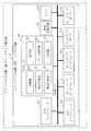
- FIG. 1shows an operation outline of the communication system according to the present embodiment.
- the communication system according to the present embodimentincludes a grand master device (GM) 10, a slave device (S1) 20, and a universal hub (HUB) 30.
- the grand master device (GM) 10is a master device.
- the slave device (S1) 20is a slave device.
- a universal hub (HUB) 30is a relay device.
- the grand master device (GM) 10 and the slave device (S 1) 20are connected via a universal hub (HUB) 30.
- the universal hub (HUB) 30is a switching hub that does not support time synchronization and is the same as the universal hub (HUB) shown in FIGS. 15 and 16.
- the relay delay of the universal hub (HUB) 30is not constant.
- FIG. 1it is shown that the relay delay of the universal hub (HUB) 30 fluctuates by + ⁇ from the average relay delay obtained by IEEE 1588 or IEEE 802.1AS. For this reason, it is necessary to obtain the offset value (Offset (N)) by adding the fluctuation width + ⁇ of the relay delay to the average time difference (Offset ave) obtained by IEEE 1588 or IEEE 802.1 AS.
- both the grand master device (GM) 10 and the slave device (S1) 20respectively hold a free run counter that measures time and a clock that measures time based on the time that the free run counter cuts.
- the free run counter held by the grand master device (GM) 10is referred to as a master counter.
- the free run counter held by the slave device (S1) 20is called a slave counter.
- a watch held by the grandmaster device (GM) 10is referred to as a master watch.
- a watch held by the slave device (S1) 20is referred to as a slave watch.
- the slave device (S1) 20corrects the value of the slave clock when the time is distributed from the grand master device (GM) 10.
- the master counterstarts counting up immediately after the grandmaster device (GM) 10 is activated. Similarly, the slave counter starts counting up immediately after the slave device (S1) 20 is activated.
- the master counter and slave counterare not changed in counter value by the communication protocol.
- the grand master device (GM) 10is reset, the master counter is also reset.
- the slave device (S1) 20is reset, the slave counter is also reset.
- the grand master device (GM) 10transmits a Sync frame, which is a time synchronization frame, to the slave device (S1) 20.
- the grand master device (GM) 10acquires the count value of the master counter and the value of the master clock when transmitting the Sync frame, and stores the acquired count value of the master counter and the value of the master clock in the Sync frame.
- the Sync frame storing the count value of the master counter and the value of the master clockis transmitted to the slave device (S1) 20.
- “t 3 (n)”is stored in the Sync frame as the count value of the master counter
- “t sync (N)”is stored in the Sync frame as the value of the master clock.
- the slave device (S1) 20acquires the count value of the slave counter and the value of the slave clock when receiving the Sync frame.
- the slave device (S1) 20acquires “t4 (N)” as the count value of the slave counter, and acquires “t rx (N)” as the value of the slave clock.
- the Sync framewhich is a time synchronization frame according to the present embodiment, includes the count value of the master counter, which is different from the Sync frame shown in FIG.
- the slave device (S1) 20transmits a DelayReq frame, which is a propagation delay measurement request, to the grand master device (GM) 10 as in FIG.
- the slave device (S1) 20holds the count value of the slave counter and the value of the slave clock at the time of transmission of the DelayReq frame.
- the grand master device (GM) 10holds the count value of the master counter and the value of the master clock when the DelayReq frame is received.
- the grand master device (GM) 10transmits a DelayResp frame, which is a propagation delay measurement response, to the slave device (S1) 20.
- the grand master device (GM) 10stores the count value of the master counter at the transmission time point of the DelayResp frame and the value of the master clock in the Delay Resp frame.
- the slave device (S1) 20holds the count value of the slave counter and the value of the slave clock when the DelayResp frame is received.
- the slave device (S1) 20holds the count value of the master counter and the value of the master clock stored in the DelayResp frame.
- the DelayReq frame and the DelayResp frameare also different from the DelayReq frame and the DelayResp frame shown in FIG.
- the slave device (S1) 20repeatedly executes propagation delay measurement (the procedure of (1) to (6) in FIG. 16) with the grand master device (GM) 10. However, as described above, the DelayReq frame and the DelayResp frame transmitted / received in FIG. 2 are different from the DelayReq frame and the DelayResp frame shown in FIG. The slave device (S1) 20 measures the difference between the propagation delay time and the count value of the slave counter and the count value of the master counter in the propagation delay measurement.
- the slave device (S1) 20calculates the average value of the propagation delay time between the grand master device (GM) 10 and the slave device (S1) 20 based on a plurality of propagation delay measurements in the past (hereinafter, average propagation delay D_ave Get). Also, the slave device (S1) 20 obtains an average value (hereinafter referred to as average count difference C_ave) of the difference between the count value of the slave counter and the count value of the master counter from a plurality of propagation delay measurements in the past.
- average count difference C_aveaverage count difference
- the average propagation delay D_aveis a value of propagation delay obtained from past propagation delay measurement, and corresponds to a measurement propagation delay value.
- the average count difference C_aveis a difference between the count value of the master counter corresponding to the average propagation delay D_ave and the count value of the slave counter, and corresponds to the delay count difference.
- RC GM_S1is a ratio of the clock frequency of the grand master device (GM) 10 to the clock frequency of the slave device (S1) 20.
- the method of calculating the clock ratiois the same as that of the IEEE 802.1AS, the description of the method of calculating the clock ratio is omitted here. Further, it is assumed that the clock frequency of the ground master device (GM) 10 is one.
- the time stamp stored in the Sync frameis only the master clock time stamp T_sync, and the master counter time stamp t3 is not stored in the Sync frame.
- the Sync frame according to the present embodimentdiffers from the Sync frame of IEEE 1588 and IEEE 802.1 AS in that the timestamp t3 of the master counter is stored.
- time stamp T_sync of the master clock stored in the Sync frameis also referred to as transmission time T_sync.
- time stamp t3 of the master counter stored in the Sync frameis also referred to as a transmission count value t3.
- the time stamp T_RX of the slave clock at the time of reception of the Sync frameis also referred to as a reception time T_RX.
- the timestamp t4 of the slave counter at the time of reception of the Sync frameis also referred to as a reception count value t4.
- the relay delay difference ⁇is a difference between the value of the relay delay by the universal hub (HUB) 30 at the time of relaying the Sync frame and the value of the relay delay included in the average propagation delay D_ave.
- the slave device (S1) 20calculates the propagation delay D_true in transmission of the Sync frame as follows.
- the slave device (S1) 20calculates the time difference between the master clock and the slave clock as Offset (N), and corrects the time of the slave clock using the value of Offset (N).
- FIG. 3shows an example of the hardware configuration of the grand master device (GM) 10 according to the present embodiment.
- FIG. 4shows an example of the functional configuration of the grand master device (GM) 10 according to the present embodiment.
- the grand master device (GM) 10 according to the present embodimentis a computer.
- the grand master device (GM) 10includes, as hardware, an input interface 101, a processor 102, an auxiliary storage device 103, a memory 104, an output interface 105, a network interface 111, a network interface 112, and a network port 113. And a network port 114. Further, as shown in FIG. 4, the grand master device (GM) 10 includes, as functional components, a control unit 106, a time management unit 107, a time measurement unit 108, a transmission unit 109, a data arbitration unit 110, and a reception unit 115.
- the auxiliary storage device 103stores programs for realizing the functions of the control unit 106, the time management unit 107, the time measurement unit 108, the transmission unit 109, the data arbitration unit 110, and the reception unit 115. These programs are loaded from the auxiliary storage device 103 into the memory 104.
- the processor 102also reads these programs from the memory 104 and executes these programs. Then, the processor 102 performs operations of a control unit 106, a time management unit 107, a time measurement unit 108, a transmission unit 109, a data arbitration unit 110, and a reception unit 115 described later.
- the processor 102schematically executes a program for realizing the functions of the control unit 106, the time management unit 107, the time measurement unit 108, the transmission unit 109, the data arbitration unit 110, and the reception unit 115. It represents.
- the input interface 101is used by the user of the grand master device (GM) 10 to input various instructions.
- the memory 104also stores the above-mentioned transmission time, transmission count value, and the like.
- the output interface 105is used to output data to an external storage medium of the grand master device (GM) 10.
- the network interface 111controls transfer of a frame between the network port 113 and the time management unit 107, the time measurement unit 108, or the data arbitration unit 110.
- the network interface 112controls transfer of a frame between the network port 114 and the time management unit 107, the time measurement unit 108, or the data arbitration unit 110.
- the network port 113 and the network port 114are physical connection ports with the network.
- the control unit 106controls the entire grand master device (GM) 10. Specifically, when the receiving unit 115 receives the DelayReq frame, the control unit 106 notifies the time management unit 107 and the time measuring unit 108 of reception of the DelayReq frame. Also, the control unit 106 instructs the time management unit 107, the time measurement unit 108, and the transmission unit 109 to transmit the DelayResp frame. When reception of the DelayReq frame is notified by the reception unit 115, the control unit 106 instructs the time management unit 107, the time measurement unit 108, and the transmission unit 109 to transmit the DelayResp frame.
- control unit 106instructs the time management unit 107, the time measurement unit 108, and the transmission unit 109 to transmit the Sync frame.
- the control unit 106controls the time management unit 107, the time measurement unit 108, and the transmission unit 109 to transmit Sync frames when the number of times of execution of the propagation delay measurement (the procedure of (1) to (6) in FIG. Direct transmission of The control unit 106 counts the transmission cycle of the Sync frame, and instructs the time management unit 107, the time measurement unit 108, and the transmission unit 109 to transmit the Sync frame at a designated cycle.
- the time management unit 107acquires the current time, and notifies the transmission unit 109 of the acquired current time. Further, the time management unit 107 acquires the current time when the transmission of the Sync frame is instructed from the control unit 106, and notifies the transmitting unit 109 of the acquired current time.
- the time measuring unit 108has a master counter 1080 which is a free run counter.
- the master counter 1080starts counting up when the grand master device (GM) 10 is activated. Further, the value of the master counter 1080 is reset when the grand master device (GM) 10 is stopped.
- the time measuring unit 108notifies the time management unit 107 of count up of the master counter 1080 each time the master counter 1080 counts up. Further, when the control unit 106 is notified of the reception of the DelayReq frame, the time measurement unit 108 acquires the current count value of the master counter 1080 and stores the acquired count value in the memory 104.
- the time measurement unit 108acquires the current count value of the master counter 1080, and notifies the transmission unit 109 of the acquired count value. Also, when instructed by the control unit 106 to transmit a Sync frame, the time measurement unit 108 acquires the current count value of the master counter 1080 and notifies the transmission unit 109 of the acquired count value.
- the transmitting unit 109generates a DelayResp frame when instructed by the control unit 106 to transmit the DelayResp frame. Also, the transmission unit 109 stores the current time notified from the time management unit 107 in the DelayResp frame. Furthermore, the transmitting unit 109 stores the current count value notified from the time measuring unit 108 in the DelayResp frame. Then, the transmission unit 109 transmits, to the slave device (S1) 20, the DelayResp frame in which the current time and the current count value are stored. More specifically, the transmission unit 109 outputs the DelayResp frame to the data arbitration unit 110. In addition, the transmission unit 109 generates a Sync frame when transmission of the Sync frame is instructed from the control unit 106.
- the transmission unit 109stores the current time notified from the time management unit 107 in the Sync frame. Furthermore, the transmitting unit 109 stores the current count value notified from the time measuring unit 108 in the Sync frame. Then, the transmission unit 109 transmits, to the slave device (S1) 20, the Sync frame in which the current time and the current count value are stored. More specifically, the transmission unit 109 outputs the Sync frame to the data arbitration unit 110.
- the current time stored in the Sync frameis the aforementioned transmission time. Also, the current count value stored in the Sync frame is the aforementioned transmission count value.
- the data arbitration unit 110determines the message type, determines whether or not the communication frame received by the network interface 111 or the network interface 112 is normal, and determines the destination. Then, when the received communication frame is a communication frame addressed to the grand master device (GM) 10, the data arbitration unit 110 transfers the communication frame to the reception unit 115. For example, if the received communication frame is a DelayReq frame, the data arbitration unit 110 transfers the DelayReq frame to the receiving unit 115. On the other hand, when the received communication frame is a communication frame addressed to another device, the data arbitration unit 110 performs relay processing. Also, the data arbitration unit 110 outputs the DelayResp frame and the Sync frame output from the transmission unit 109 to the network interface 111 or the network interface 112.
- the receiving unit 115receives the DelayReq frame transmitted from the slave device (S1) 20. That is, the receiving unit 115 receives the DelayReq frame transferred from the data arbitration unit 110. Also, when the receiving unit 115 receives the DelayReq frame, the receiving unit 115 notifies the control unit 106 of the reception of the DelayReq frame.
- the network interface 111, the network interface 112, the network port 113 and the network port 114 of FIG. 4are the same as those shown in FIG.
- FIG. 5shows an example of the hardware configuration of the slave device (S1) 20 according to the present embodiment.
- FIG. 6shows an example of a functional configuration of the slave device (S1) 20 according to the present embodiment.
- the slave device (S1) 20 according to the present embodimentis a computer.
- the slave device (S1) 20includes, as hardware, an input interface 201, a processor 202, an auxiliary storage device 203, a memory 204, an output interface 205, a network interface 211, a network interface 212, a network port 213 and A network port 214 is provided. Further, as shown in FIG. 6, the slave device (S1) 20 includes a control unit 206, a time management unit 207, a time measurement unit 208, a transmission unit 209, a data arbitration unit 210, and a reception unit 215 as functional components.
- the auxiliary storage device 203stores programs for realizing the functions of the control unit 206, time management unit 207, time measurement unit 208, transmission unit 209, data arbitration unit 210, and reception unit 215. These programs are loaded from the auxiliary storage device 203 into the memory 204.
- the processor 202also reads these programs from the memory 204 and executes these programs. Then, the processor 202 performs operations of a control unit 206, a time management unit 207, a time measurement unit 208, a transmission unit 209, a data arbitration unit 210, and a reception unit 215 described later.
- the processor 202schematically executes a program for realizing the functions of the control unit 206, the time management unit 207, the time measurement unit 208, the transmission unit 209, the data arbitration unit 210, and the reception unit 215. It represents.
- the input interface 201is used by the user of the slave device (S1) 20 to input various instructions.
- the memory 204also stores the transmission time, transmission count value, reception time, reception count value, average count difference C_ave, average propagation delay D_ave, and the like described above.
- the output interface 205is used to output data to the external storage medium of the slave device (S1) 20.
- the network interface 211controls transfer of a frame between the network port 213 and the time management unit 207, the time measurement unit 208, or the data arbitration unit 210.
- the network interface 212controls transfer of a frame between the network port 214 and the time management unit 207, the time measurement unit 208, or the data arbitration unit 210.
- the network port 213 and the network port 214are
- the control unit 206controls the entire slave device (S1) 20. Specifically, the control unit 206 instructs the transmission unit 209 to transmit the DelayReq frame. Also, the control unit 206 notifies the time management unit 207 and the time measurement unit 208 of transmission of the DelayReq frame. Also, when the receiving unit 215 receives the DelayResp frame, the control unit 206 notifies the time management unit 207 and the time measuring unit 208 of the reception of the DelayResp frame. Furthermore, when the receiving unit 215 receives the Sync frame, the control unit 206 notifies the time management unit 207 and the time measuring unit 208 of the reception of the Sync frame. The control unit 206 also instructs the time management unit 207 to correct the time.
- the time management unit 207acquires the current time, and stores the acquired current time in the memory 204. Further, the time management unit 207 acquires the current time when notified of the reception of the Sync frame from the control unit 206, and stores the acquired current time in the memory 204. The current time when the Sync frame is received is the above-mentioned reception time. Also, when time correction is instructed from the control unit 206, the time management unit 207 corrects the time of the slave clock.
- the time management unit 207includes the transmission time and transmission count value acquired by the reception unit 215, the reception count value acquired by the time measurement unit 208, the reception time, and the average propagation delay D_ave which is a measurement propagation delay value.
- the time of the slave clockis corrected using the average count difference C_ave which is the delay count difference.
- the time management unit 207calculates the relay delay difference ⁇ based on Equation 3 described above, and calculates the propagation delay D_true based on Equation 4 described above.
- the time management unit 207calculates Offset (N) based on Equation 5 described above.
- the time management unit 207corrects the time of the slave clock on the basis of Equation 6 described above.
- the time management unit 207corresponds to an acquisition unit and a time correction unit.
- the time measuring unit 208has a slave counter 2080 which is a free run counter.
- the slave counter 2080starts counting up when the slave device (S1) 20 starts up. Also, the value of the slave counter 2080 is reset when the slave device (S1) 20 stops.
- the time measuring unit 208notifies the time management unit 207 that the slave counter 2080 has counted up. Further, when notified of the transmission of the DelayReq frame from the control unit 206, the time measuring unit 208 acquires the current count value of the slave counter 2080, and stores the acquired count value in the memory 204.
- the time measuring unit 208acquires the current count value of the slave counter 2080 when receiving notification of the DelayResp frame from the control unit 206, and stores the acquired count value in the memory 204. Further, when notified of the reception of the Sync frame from the control unit 206, the time measuring unit 208 acquires the current count value of the slave counter 2080, and stores the acquired count value in the memory 204.
- the count value at the time of reception of the Sync frameis the above-mentioned reception count value.
- the time measurement unit 208 and the time management unit 207correspond to an acquisition unit.
- the transmitting unit 209generates a DelayReq frame when instructed by the control unit 206 to transmit the DelayReq frame. Then, the transmission unit 209 transmits the DelayReq frame to the grand master device (GM) 10. More specifically, the transmission unit 209 outputs the DelayReq frame to the data arbitration unit 210.
- the data arbitration unit 210determines the message type, determines whether or not the communication frame received by the network interface 211 or the network interface 212 is normal, and determines the destination. Then, when the received communication frame is a communication frame addressed to the slave device (S1) 20, the data arbitration unit 210 transfers the communication frame to the reception unit 215. For example, if the received communication frame is a DelayResp frame, the data arbitration unit 110 transfers the DelayResp frame to the receiving unit 115. In addition, if the received communication frame is a Sync frame, the data arbitration unit 110 transfers the Sync frame to the receiving unit 115. On the other hand, when the received communication frame is a communication frame addressed to another device, the data arbitration unit 210 performs relay processing. Also, the data arbitration unit 210 outputs the DelayReq frame output from the transmission unit 209 to the network interface 211 or the network interface 212.
- the receiving unit 215receives the DelayResp frame transmitted from the grand master device (GM) 10. That is, the receiving unit 115 receives the DelayResp frame transferred from the data arbitration unit 210.
- the receiving unit 215acquires the time and count value stored by the grand master device (GM) 10 from the received DelayResp frame. Then, the reception unit 215 stores the acquired time and count value in the memory 204. Further, when the receiving unit 215 receives the DelayResp frame, the receiving unit 215 notifies the control unit 206 of the reception of the DelayResp frame.
- the receiving unit 215receives the Sync frame transmitted from the grand master device (GM) 10. That is, the receiving unit 115 receives the Sync frame transferred from the data arbitration unit 210.
- the receiving unit 215acquires the time (transmission time) and the count value (transmission count value) stored by the grandmaster device (GM) 10 from the received Sync frame. Then, the reception unit 215 stores the acquired transmission time and transmission count value in the memory 204. In addition, when the receiving unit 215 receives the Sync frame, the receiving unit 215 notifies the control unit 206 of the reception of the Sync frame.
- the network interface 211, the network interface 212, the network port 213 and the network port 214 of FIG. 6are the same as those shown in FIG.
- FIG. 7shows a count up and time measurement flow.
- the count-up and time measurement flow shown in FIG. 7is commonly performed by the grand master device (GM) 10 and the slave device (S1) 20.
- FIG. 8shows the transmission flow of the DelayReq frame by the slave device (S1) 20.
- the control unit 206waits for the transmission timing of the DelayReq frame to come (step S201).
- the control unit 206instructs the transmission unit 209 to transmit the DelayReq frame.
- the transmitting unit 209transmits the DelayReq frame to the grand master device (GM) 10 (step S203). Further, in parallel with the transmission instruction of the DelayReq frame to the transmission unit 209, the control unit 206 notifies the time management unit 207 and the time measurement unit 208 of transmission of the DelayReq frame.
- the time management unit 207acquires the current time as the transmission time of the DelayReq frame based on the notification from the control unit 206, and stores the acquired current time in the memory 204 (step S204). Further, based on the notification from the control unit 206, the time measurement unit 208 acquires the current count value of the slave counter 2080 as the count value of the slave counter 2080 at the time of transmission of the DelayReq frame, and stores the acquired count value in the memory 204. It stores (step S204).
- FIG. 9shows the reception flow of the DelayReq frame and the transmission flow of the DelayResp frame by the grand master device (GM) 10.
- the time management unit 107acquires the reception time of the DelayReq frame (step S303). Further, the time measuring unit 108 acquires the value of the master counter 1080 at the time of receiving the DelayReq frame (step S303). More specifically, the receiving unit 115 notifies the control unit 106 of the reception of the DelayReq frame. The control unit 106 notifies the time management unit 107 and the time measurement unit 108 of the reception of the DelayReq frame.
- the time management unit 107acquires the current time based on the notification from the control unit 106, and stores the acquired current time in the memory 104. Further, based on the notification from the control unit 106, the time measurement unit 108 acquires the current count value of the master counter 1080, and stores the acquired count value in the memory 104. Also, the transmission unit 109 generates a DelayResp frame (step S304). More specifically, the control unit 106 instructs the time management unit 107, the time measurement unit 108, and the transmission unit 109 to transmit a DelayResp frame. The time management unit 107 acquires the current time, and notifies the transmission unit 109 of the acquired current time.
- the time measurement unit 108acquires the current count value of the master counter 1080 and notifies the transmission unit 109 of the acquired count value.
- the transmission unit 109generates a DelayResp frame, and stores the time notified from the time management unit 107 and the count value notified from the time measurement unit 108 in the generated DelayResp frame. Then, the transmission unit 109 transmits the DelayResp frame generated in step S304 to the slave device (S1) 20 (step S305).
- FIG. 10shows a reception flow of the DelayResp frame by the slave device (S1) 20.
- the time management unit 207acquires the reception time of the DelayResp frame (step S403). Further, the time measuring unit 208 acquires the value of the slave counter 2080 at the time of receiving the DelayResp frame (step S403). More specifically, the receiving unit 215 notifies the control unit 206 of the reception of the DelayResp frame. The control unit 206 notifies the time management unit 207 and the time measurement unit 208 of the reception of the DelayResp frame.
- the time management unit 207acquires the current time based on the notification from the control unit 206, and stores the acquired current time in the memory 204. Further, based on the notification from the control unit 206, the time measuring unit 208 acquires the current count value of the slave counter 2080, and stores the acquired count value in the memory 204.
- the reception unit 215extracts the transmission time of the DelayResp frame and the value of the master counter 1080 at the time of transmission of the DelayResp frame from the DelayResp frame (step S404). Then, the reception unit 215 stores the extracted transmission time and the value of the master counter 1080 in the memory 204.
- step S404is to be performed after step S403 in FIG. 10, step S403 and step S404 may be performed in parallel.
- FIG. 11shows the flow of transmission of Sync frames by the grandmaster apparatus (GM) 10.
- the control unit 106waits for the transmission timing of the Sync frame to arrive (step S501).
- the control unit 106instructs the time management unit 107, the time measurement unit 108, and the transmission unit 109 to transmit the Sync frame.
- the time management unit 107acquires the current time, and notifies the transmission unit 109 of the acquired current time (step S503).
- the time measuring unit 108acquires the current count value of the master counter 1080, and notifies the transmission unit 109 of the acquired count value (step S503).
- the transmitting unit 109generates a Sync frame, and stores the time notified from the time management unit 107 and the count value notified from the time measuring unit 108 in the generated Sync frame (step S 504). Then, the transmitting unit 109 transmits the Sync frame to the slave device (S1) 20 (step S505).
- FIG. 12shows the reception flow of the Sync frame by the slave device (S1) 20.
- the time management unit 207acquires the reception time of the Sync frame (step S603). Further, the time measuring unit 208 acquires the value (reception count value) of the slave counter 2080 at the time of receiving the Sync frame (step S603). More specifically, the receiving unit 215 notifies the control unit 206 of the reception of the Sync frame. The control unit 206 notifies the time management unit 207 and the time measurement unit 208 of the reception of the Sync frame. The time management unit 207 acquires the current time based on the notification from the control unit 206, and stores the acquired current time in the memory 204.
- step S604is to be performed after step S603, but step S603 and step S604 may be performed in parallel.
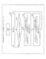
- FIG. 13shows a time correction flow by the slave device (S1) 20.
- the time management unit 207waits for a time correction instruction from the control unit 206 (step S701).
- time management unit 207determines whether average propagation delay D_ave and average count difference C_ave exist in memory 204 (step S703). ). If the average propagation delay D_ave and the average count difference C_ave do not exist in the memory 204 (NO in step S703), the process returns to step S701. If the average propagation delay D_ave and the average count difference C_ave exist in the memory 204 (YES in step S703), the time management unit 207 calculates the relay delay difference ⁇ (step S704).
- the time management unit 207calculates the relay delay difference ⁇ in accordance with Equation 3 described above.
- the time management unit 207calculates the propagation delay D_true (step S705). Specifically, the time management unit 207 calculates the propagation delay D_true in accordance with Equation 4 described above.
- the time management unit 207calculates Offset (N) (step S706). Specifically, the time management unit 207 calculates Offset (N) in accordance with Equation 5 described above.
- the time management unit 207corrects the time of the slave clock using Offset (N) (step S 707). Specifically, the time management unit 207 corrects the time according to Equation 6 described above.
- the processor 102 illustrated in FIG. 3 and the processor 202 illustrated in FIG. 5are integrated circuits (ICs) that perform processing.
- the processor 102 and the processor 202are, respectively, a central processing unit (CPU), a digital signal processor (DSP), and the like.
- the memory 104 shown in FIG. 3 and the memory 204 shown in FIG. 5are each a RAM (Random Access Memory).
- the auxiliary storage device 103 shown in FIG. 3 and the auxiliary storage device 203 shown in FIG. 5are respectively a ROM (Read Only Memory), a flash memory, an HDD (Hard Disk Drive) and the like.
- the network interface 112, the network interface 211 shown in FIG. 5, and the network interface 212each include a receiver for receiving data and a transmitter for transmitting data.
- the network interface 111, the network interface 112, the network interface 211, and the network interface 212are, for example, a communication chip or a NIC (Network Interface Card).
- the auxiliary storage device 103also stores an OS (Operating System). Then, at least part of the OS is executed by the processor 102.
- the processor 102executes a program that implements the functions of the control unit 106, the time management unit 107, the time measurement unit 108, the transmission unit 109, the data arbitration unit 110, and the reception unit 115 while executing at least a part of the OS.
- the processor 102executes the OS to perform task management, memory management, file management, communication control, and the like.
- the auxiliary storage device 203also stores an OS (Operating System). Then, at least part of the OS is executed by the processor 202.
- the processor 202executes a program that implements the functions of the control unit 206, the time management unit 207, the time measurement unit 208, the transmission unit 209, the data arbitration unit 210, and the reception unit 215 while executing at least a part of the OS.
- the processor 202executes the OS, task management, memory management, file management, communication control, and the like are performed.
- At least one of information, data, a signal value, and a variable value indicating the result of processing of control unit 106, time management unit 107, time measurement unit 108, transmission unit 109, data arbitration unit 110, and reception unit 115It is stored in the storage device 103, the memory 104, the register in the processor 102 and / or the cache memory.
- the programs for realizing the functions of the control unit 106, the time management unit 107, the time measurement unit 108, the transmission unit 109, the data arbitration unit 110, and the reception unit 115are magnetic disk, flexible disk, optical disk, compact disk, Blu-ray (registration It may be stored in a portable storage medium such as a trademarked disc, a DVD or the like.
- At least one of information, data, signal value, and variable value indicating the result of processing of control unit 206, time management unit 207, time measurement unit 208, transmission unit 209, data arbitration unit 210, and reception unit 215It is stored in the storage device 203, the memory 204, the register in the processor 202 and / or the cache memory.
- programs for realizing the functions of the control unit 206, time management unit 207, time measurement unit 208, transmission unit 209, data arbitration unit 210, and reception unit 215are magnetic disk, flexible disk, optical disk, compact disk, Blu-ray (registration It may be stored in a portable storage medium such as a trademarked disc, a DVD or the like.
- GMgrand master device
- IClogic integrated circuit
- GAgate array
- ASICapplication specific integrated circuit
- FPGAfield-programmable gate array
- slave device (S1) 20may be realized by a processing circuit such as a logic IC, a GA, an ASIC, or an FPGA.
- processing circuitthe upper concept of the processor, the memory, the combination of the processor and the memory, and the processing circuit. That is, the processor, the memory, the combination of the processor and the memory, and the processing circuit are specific examples of the "processing circuit".
Landscapes
- Engineering & Computer Science (AREA)
- Computer Networks & Wireless Communication (AREA)
- Signal Processing (AREA)
- Synchronisation In Digital Transmission Systems (AREA)
Abstract
Description
Translated fromJapanese本発明は、マスタ装置とスレーブ装置とが含まれる通信システムに関する。The present invention relates to a communication system including a master device and a slave device.
近年、IEEE1588またはIEEE802.1ASといった時刻同期プロトコルが搭載されたネットワーク装置が普及しつつある。
IEEE1588及びIEEE802.1ASでは、時刻源となるマスタ装置(以下、グランドマスタ装置ともいう)がスレーブ装置に時刻情報が格納されたSyncフレームを送信する。そして、スレーブ装置はSyncフレームを受信するとSyncフレームからマスタ装置の時刻情報を取得する。そして、スレーブ装置は、スレーブ装置の時刻を補正する。これにより。スレーブ装置はマスタ装置に同期することができる。
以下、IEEE1588のプロトコルを図14を用いて説明する。なお、以下の(1)~(9)は図14の(1)~(9)に対応する。In recent years, network devices equipped with a time synchronization protocol such as IEEE 1588 or IEEE 802.1 AS are becoming widespread.
In IEEE 1588 and IEEE 802.1AS, a master device (hereinafter, also referred to as a grand master device) as a time source transmits a Sync frame in which time information is stored to a slave device. Then, when receiving the Sync frame, the slave device acquires time information of the master device from the Sync frame. Then, the slave device corrects the time of the slave device. By this. The slave device can synchronize to the master device.
The protocol of IEEE 1588 will be described below with reference to FIG. The following (1) to (9) correspond to (1) to (9) in FIG.
(1)グランドマスタ装置(GM)はSyncフレームの送信に際して送信時刻のタイムスタンプt1(以下、単に送信時刻t1という)を取得し、Syncフレームに送信時刻t1を格納する。そして、グランドマスタ装置(GM)は送信時刻t1が格納されたSyncフレームをスレーブ装置(S1)に送信する。図14では、送信時刻t1が格納されたSyncフレームをSync(t1)と表記している。
(2)スレーブ装置(S1)はグランドマスタ装置(GM)からSyncフレームを受信すると、Syncフレームの受信時刻のタイムスタンプt2(以下、単に受信時刻t2という)を取得し、受信時刻t2を保持する。また、スレーブ装置(S1)はSyncフレームに格納された送信時刻t1を抽出し、送信時刻t1を保持する。
(3)スレーブ装置(S1)はグランドマスタ装置(GM)に伝搬遅延計測要求フレームであるDelayReqフレームを送信する。この時、スレーブ装置(S1)は、DelayReqフレームの送信時刻のタイムスタンプt3(以下、単に送信時刻t3という)を取得し、送信時刻t3を保持する。
(4)グランドマスタ装置(GM)はスレーブ装置(S1)からDelayReqフレームを受信する。また、グランドマスタ装置(GM)はDelayReqフレームの受信時刻のタイムスタンプt4(以下、単に受信時刻t4という)を取得し、受信時刻t4を保持する。
(5)グランドマスタ装置(GM)は受信時刻t4を伝搬遅延計測応答フレームであるDelayRespフレームに格納し、受信時刻t4が格納されたDelayRespフレームをスレーブ装置(S1)に送信する。図14では、受信時刻t4が格納されたDelayRespフレームをDelayResp(t4)と表記している。
(6)スレーブ装置(S1)はDelayRespフレームに格納された受信時刻t4を抽出し、受信時刻t4を保持する。
(7)スレーブ装置(S1)は保持している送信時刻t1、受信時刻t2、送信時刻t3及び受信時刻t4を用いてグランドマスタ装置(GM)とスレーブ装置(S1)との間の伝搬遅延時間を以下にて算出する。
伝搬遅延時間:D={(t4-t1)+(t2-t3)}/2
(8)グランドマスタ装置(GM)はある時刻で、送信開始時刻のタイムスタンプt_tx(以下、単に送信開始時刻t_txという)を取得し、送信開始時刻t_txをSyncフレームに格納してスレーブ装置(S1)に送信する。図14では、送信開始時刻t_txが格納されたSyncフレームをSync(t_tx)と表記している。
(9)スレーブ装置(S1)はSync(t_tx)を受信するとSync(t_tx)の受信時刻のタイムスタンプt_rx(以下、単に受信時刻t_rxという)を取得し、受信時刻t_rxを保持する。更に、スレーブ装置(S1)は保持している送信開始時刻t_tx、受信時刻t_rx、及び上記の(7)で算出した伝搬遅延時間Dから、以下にて、グランドマスタ装置(GM)とスレーブ装置(S1)との時刻差を算出し、算出した時刻差を用いてスレーブ装置(S1)の時刻を補正する。
グランドマスタ装置(GM)との時刻差:Offset=t_tx+D-t_rx(1) When transmitting a Sync frame, the grand master device (GM) acquires a time stamp t1 of transmission time (hereinafter simply referred to as transmission time t1), and stores the transmission time t1 in the Sync frame. Then, the grand master device (GM) transmits the Sync frame in which the transmission time t1 is stored to the slave device (S1). In FIG. 14, the Sync frame in which the transmission time t1 is stored is described as Sync (t1).
(2) When the slave device (S1) receives the Sync frame from the grand master device (GM), the slave device (S1) acquires a time stamp t2 of the reception time of the Sync frame (hereinafter simply referred to as reception time t2) and holds the reception time t2. . Also, the slave device (S1) extracts the transmission time t1 stored in the Sync frame, and holds the transmission time t1.
(3) The slave device (S1) transmits a DelayReq frame, which is a propagation delay measurement request frame, to the grand master device (GM). At this time, the slave device (S1) acquires a time stamp t3 of the transmission time of the DelayReq frame (hereinafter simply referred to as transmission time t3), and holds the transmission time t3.
(4) The grand master device (GM) receives the DelayReq frame from the slave device (S1). Also, the grand master apparatus (GM) acquires a time stamp t4 (hereinafter, simply referred to as reception time t4) of the reception time of the DelayReq frame, and holds the reception time t4.
(5) The grand master device (GM) stores the reception time t4 in the DelayResp frame which is a propagation delay measurement response frame, and transmits the DelayResp frame in which the reception time t4 is stored to the slave device (S1). In FIG. 14, the DelayResp frame in which the reception time t4 is stored is described as DelayResp (t4).
(6) The slave device (S1) extracts the reception time t4 stored in the DelayResp frame, and holds the reception time t4.
(7) The propagation delay time between the grand master device (GM) and the slave device (S1) using the transmission time t1, the reception time t2, the transmission time t3 and the reception time t4 held by the slave device (S1) Is calculated as follows.
Propagation delay time: D = {(t4−t1) + (t2−t3)} / 2
(8) The grand master device (GM) acquires a time stamp t_tx of the transmission start time (hereinafter simply referred to as the transmission start time t_tx) at a certain time, stores the transmission start time t_tx in the Sync frame, and stores the slave device (S1). Send to). In FIG. 14, the Sync frame in which the transmission start time t_tx is stored is described as Sync (t_tx).
(9) Upon receiving Sync (t_tx), the slave device (S1) acquires a time stamp t_rx (hereinafter simply referred to as reception time t_rx) of the reception time of Sync (t_tx), and holds the reception time t_rx. Furthermore, from the transmission start time t_tx held by the slave device (S1), the reception time t_rx, and the propagation delay time D calculated in (7) above, the grand master device (GM) and the slave device The time difference with S1) is calculated, and the time of the slave device (S1) is corrected using the calculated time difference.
Time difference with the grand master device (GM): Offset = t_tx + D-t_rx
これらの時刻同期プロトコルは、FA(Factory Automation)システム内の装置間の時刻同期に適用されている。装置間で時刻同期を実施することで、短い通信周期のリアルタイム通信を実現することが可能になり、更に、異なる複数の通信プロトコルを時分割で混在させることが可能になる。These time synchronization protocols are applied to time synchronization between devices in a factory automation (FA) system. By performing time synchronization between devices, it becomes possible to realize real-time communication with a short communication cycle, and furthermore, it becomes possible to mix different communication protocols in time division.
IEEE1588またはIEEE802.1ASでは、伝搬遅延が定期的に計測され、装置間での伝搬遅延時間が定期的に更新される。したがって、IEEE1588またはIEEE802.1ASでは、Syncフレームの送信とは別のタイミングで計測された伝搬遅延時間を使用して時刻補正が実施される。このとき、Syncフレームの送信時に計測された伝搬遅延時間が別のタイミングで計測された伝搬遅延時間と大きく異なる場合がある。この場合は、スレーブ装置(S1)は時刻補正を正確にできないため、スレーブ装置(S1)とグランドマスタ装置(GM)との間に同期ずれが生じる。In IEEE 1588 or IEEE 802.1AS, propagation delay is measured periodically, and propagation delay time between devices is periodically updated. Therefore, in IEEE 1588 or IEEE 802.1AS, time correction is performed using the propagation delay time measured at a timing different from the transmission of the Sync frame. At this time, the propagation delay time measured at the time of transmission of the Sync frame may be largely different from the propagation delay time measured at another timing. In this case, since the slave device (S1) can not correct the time correctly, a synchronization deviation occurs between the slave device (S1) and the grand master device (GM).
このような同期ずれは、例えば、図15のように時刻同期プロトコルを用いた時刻同期が行われるネットワークに時刻同期非対応のスイッチングハブ(以下、汎用ハブ(HUB)という)が混在する場合に発生する。
ネットワークに汎用ハブ(HUB)が混在している場合は、汎用ハブ(HUB)のファームウェアの処理時間の揺らぎ、送信待ちにより、汎用ハブ(HUB)での中継遅延時間が一定とならない。このため、スレーブ装置(S1)は正確に伝搬遅延時間を計測することができない。この結果、汎用ハブ(HUB)を介してグランドマスタ装置(GM)接続されたスレーブ装置(S1)はグランドマスタ装置(GM)との時刻差を正確に算出することができない。Such a synchronization deviation occurs, for example, when a network in which time synchronization is performed using a time synchronization protocol is mixed with a switching hub (hereinafter referred to as a universal hub (HUB)) incompatible with time synchronization as shown in FIG. Do.
When the universal hub (HUB) is mixed in the network, the relay delay time at the universal hub (HUB) is not constant due to the fluctuation of the processing time of the firmware of the universal hub (HUB) and the transmission waiting. Therefore, the slave device (S1) can not accurately measure the propagation delay time. As a result, the slave device (S1) connected to the grand master device (GM) via the universal hub (HUB) can not accurately calculate the time difference with the grand master device (GM).
特許文献1の技術では、伝搬遅延が揺らぐ場合に、複数回の伝搬遅延計測を行い、最も通信時間が短い通信を伝搬遅延の揺らぎがない通信と仮定する。そして、特許文献1の技術では、伝搬遅延の揺らぎがないと仮定した通信での伝搬遅延計測値を用いて時刻同期を行う。
しかしながら、この方式では、図15のように、汎用ハブ(HBU)での中継時間の揺らぎにより、グランドマスタ装置(GM)がSyncフレームを送信し、スレーブ装置(S1)がSyncフレームを受信するまでの伝搬遅延時間が予め算出した伝搬遅延時間の平均値と大幅に異なる場合がある。この場合には、スレーブ装置(S1)が補正した時刻はグランドマスタ装置(GM)の時刻から大幅にずれる。
以下、図16を用いて、従来の時刻同期方式の課題を説明する。なお、以下の(1)~(6)は、図16の(1)~(6)に対応する。In the technique of
However, in this method, as shown in FIG. 15, due to the fluctuation of the relay time in the general-purpose hub (HBU), the grand master device (GM) transmits the Sync frame and the slave device (S1) receives the Sync frame. In some cases, the propagation delay time of the signal may be significantly different from the average value of the propagation delay times calculated in advance. In this case, the time corrected by the slave device (S1) largely deviates from the time of the grand master device (GM).
Hereinafter, the problem of the conventional time synchronization system will be described with reference to FIG. The following (1) to (6) correspond to (1) to (6) in FIG.
(1)グランドマスタ装置(GM)とスレーブ装置(S1)はSyncフレーム、DelayReqフレーム及びDelayRespフレームを複数交換し、伝搬遅延時間を算出する。(図16では、当該シーケンスの図示は省略している)。ここで、最小伝搬遅延時間はD_min=3と算出されたとする。また、このときの汎用ハブ(HUB)の中継遅延時間はRT_min=1であるとする。
(2)グランドマスタ装置(GM)は、時刻11でタイムスタンプt_sync(=11)をSyncフレームに格納し、t_sync(=11)が格納されたSyncフレームをスレーブ装置(S1)に送信する。
(3)汎用ハブ(HUB)でSyncフレームを中継したときの中継遅延時間は3(RT=3)であるとする。
(4)スレーブ装置(S1)は、時刻t_rx=10でSyncフレームを受信する。また、スレーブ装置(S1)は、タイムスタンプt_rx(=10)を取得する。
(5)スレーブ装置(S1)は、タイムスタンプt_sync(=11)、タイムスタンプt_rx(=10)及び最小伝搬遅延時間D_min(=3)を使用してグランドマスタ装置(GM)との時刻差(Offset_GM)を以下にて算出する。
Offset_GM=t_sync+D_min-t_rx
=11+3-10=4
(6)スレーブ装置(S1)は、時刻11で以下にてスレーブ装置(S1)の時刻補正を行う。
Time_c=Time+Offset_GM=11+4=15(1) The grand master device (GM) and the slave device (S1) exchange a plurality of Sync frames, DelayReq frames and DelayResp frames, and calculate propagation delay times. (In FIG. 16, the illustration of the sequence is omitted). Here, it is assumed that the minimum propagation delay time is calculated as D_min = 3. Further, it is assumed that the relay delay time of the universal hub (HUB) at this time is RT_min = 1.
(2) The grand master device (GM) stores the time stamp t_sync (= 11) in the Sync frame at
(3) It is assumed that the relay delay time when relaying the Sync frame by the universal hub (HUB) is 3 (RT = 3).
(4) The slave device (S1) receives the Sync frame at time t_rx = 10. Also, the slave device (S1) acquires a time stamp t_rx (= 10).
(5) The slave device (S1) uses the time stamp t_sync (= 11), the time stamp t_rx (= 10) and the minimum propagation delay time D_min (= 3) to set the time difference with the grand master device (GM) Offset_GM) is calculated as follows.
Offset_GM = t_sync + D_min-t_rx
= 11 + 3-10 = 4
(6) The slave device (S1) performs time correction of the slave device (S1) below at
Time_c = Time + Offset_GM = 11 + 4 = 15
以上の手順において、グランドマスタ装置(GM)がt_sync(=11)が格納されたSyncフレームを送信してから、スレーブ装置(S1)が受信するまでの実際の時間はD_true=5である。また、スレーブ装置(S1)が時刻補正したときのグランドマスタ装置(GM)の時刻は17である。よって、スレーブ装置(S1)の時刻とグランドマスタ装置(GM)の時刻との間には2の誤差が生じる。
このように、従来の時刻同期方式によれば、中継装置である汎用ハブ(HUB)の中継遅延が一定でない場合は、正確な時刻同期を実現することができないという課題がある。In the above procedure, the actual time from the transmission of the Sync frame in which the grand master device (GM) stores t_sync (= 11) to the reception of the slave device (S1) is D_true = 5. The time of the grand master device (GM) when the slave device (S1) corrects the time is 17. Therefore, an error of 2 occurs between the time of the slave device (S1) and the time of the grand master device (GM).
As described above, according to the conventional time synchronization method, there is a problem that accurate time synchronization can not be realized when the relay delay of the universal hub (HUB) as the relay device is not constant.
本発明は、このような課題を解決することを主な目的とする。より具体的には、本発明は、中継装置の中継遅延が一定でない場合にも、正確な時刻同期を実現することを主な目的とする。The main object of the present invention is to solve such problems. More specifically, the main object of the present invention is to realize accurate time synchronization even when the relay delay of the relay apparatus is not constant.
本実施の形態に係る通信システムは、
中継遅延が一定でない中継装置を介して接続されるマスタ装置とスレーブ装置とを有し、
前記マスタ装置は、
フリーランカウンタであるマスタカウンタと、
時刻同期のための時刻同期フレームを送信するタイミングで、現在時刻を前記時刻同期フレームの送信時刻として取得し、前記マスタカウンタのカウント値を送信カウント値として取得し、前記送信時刻と前記送信カウント値とを前記時刻同期フレームに格納し、前記時刻同期フレームを前記スレーブ装置に送信する送信部とを有し、
前記スレーブ装置は、
フリーランカウンタであるスレーブカウンタと、
前記時刻同期フレームを受信する受信部と、
前記時刻同期フレームの受信時刻と、前記受信時刻における前記スレーブカウンタのカウント値である受信カウント値とを取得する取得部と、
前記送信時刻と前記送信カウント値と前記受信時刻と前記受信カウント値と、過去の計測から得られた伝搬遅延の値である計測伝搬遅延値と、前記計測伝搬遅延値に対応する前記マスタカウンタのカウント値と前記スレーブカウンタのカウント値とから求められる遅延カウント差とを用いて、前記スレーブ装置の時刻を補正する時刻補正部とを有する。The communication system according to the present embodiment is
It has a master device and a slave device connected via a relay device whose relay delay is not constant,
The master device is
A master counter which is a free run counter,
At the timing of transmitting a time synchronization frame for time synchronization, the current time is acquired as the transmission time of the time synchronization frame, the count value of the master counter is acquired as the transmission count value, and the transmission time and the transmission count value And a transmitter configured to store the time synchronization frame in the time synchronization frame, and transmitting the time synchronization frame to the slave device;
The slave device is
A slave counter which is a free run counter,
A receiving unit that receives the time synchronization frame;
An acquisition unit that acquires a reception time of the time synchronization frame and a reception count value that is a count value of the slave counter at the reception time;
The transmission time, the transmission count value, the reception time, the reception count value, a measurement propagation delay value that is a value of propagation delay obtained from past measurement, and the master counter corresponding to the measurement propagation delay value And a time correction unit that corrects the time of the slave device using a count value and a delay count difference obtained from the count value of the slave counter.
本発明によれば、中継装置の中継遅延が一定でない場合にも、正確な時刻同期を実現することができる。According to the present invention, accurate time synchronization can be realized even when the relay delay of the relay apparatus is not constant.
以下、本発明の実施の形態について、図を用いて説明する。以下の実施の形態の説明及び図面において、同一の符号を付したものは、同一の部分又は相当する部分を示す。Hereinafter, embodiments of the present invention will be described with reference to the drawings. In the following description of the embodiments and drawings, the same reference numerals denote the same or corresponding parts.
実施の形態1.
***概要の説明***
図1は、本実施の形態に係る通信システムの動作概要を示す。
本実施の形態に係る通信システムは、グランドマスタ装置(GM)10、スレーブ装置(S1)20及び汎用ハブ(HUB)30で構成される。
グランドマスタ装置(GM)10は、マスタ装置である。スレーブ装置(S1)20はスレーブ装置である。汎用ハブ(HUB)30は中継装置である。
グランドマスタ装置(GM)10とスレーブ装置(S1)20は汎用ハブ(HUB)30を介して接続されている。
汎用ハブ(HUB)30は、時刻同期非対応のスイッチングハブであり、図15及び図16で示した汎用ハブ(HUB)と同じである。つまり、汎用ハブ(HUB)30の中継遅延は一定ではない。図1では、汎用ハブ(HUB)30の中継遅延が、IEEE1588またはIEEE802.1ASで得られた平均中継遅延から+Δだけ変動していることが示されている。このため、IEEE1588またはIEEE802.1ASで得られた平均時間差(Offset ave)に中継遅延の変動幅+Δを加算して、オフセット値(Offset(N))を得る必要がある。
*** Brief Description ***
FIG. 1 shows an operation outline of the communication system according to the present embodiment.
The communication system according to the present embodiment includes a grand master device (GM) 10, a slave device (S1) 20, and a universal hub (HUB) 30.
The grand master device (GM) 10 is a master device. The slave device (S1) 20 is a slave device. A universal hub (HUB) 30 is a relay device.
The grand master device (GM) 10 and the slave device (S 1) 20 are connected via a universal hub (HUB) 30.
The universal hub (HUB) 30 is a switching hub that does not support time synchronization and is the same as the universal hub (HUB) shown in FIGS. 15 and 16. That is, the relay delay of the universal hub (HUB) 30 is not constant. In FIG. 1, it is shown that the relay delay of the universal hub (HUB) 30 fluctuates by + Δ from the average relay delay obtained by IEEE 1588 or IEEE 802.1AS. For this reason, it is necessary to obtain the offset value (Offset (N)) by adding the fluctuation width + Δ of the relay delay to the average time difference (Offset ave) obtained by IEEE 1588 or IEEE 802.1 AS.
本実施の形態では、グランドマスタ装置(GM)10及びスレーブ装置(S1)20はともに、時間を計測するフリーランカウンタと、フリーランカウンタが刻む時間を基に時刻を計測する時計をそれぞれ保持する。以下、グランドマスタ装置(GM)10が保持するフリーランカウンタはマスタカウンタという。また、スレーブ装置(S1)20が保持するフリーランカウンタはスレーブカウンタという。また、グランドマスタ装置(GM)10が保持する時計をマスタ時計という。また、スレーブ装置(S1)20が保持する時計をスレーブ時計という。
また、スレーブ装置(S1)20は、グランドマスタ装置(GM)10から時刻が配信されるとスレーブ時計の値を補正する。
マスタカウンタはグランドマスタ装置(GM)10の起動直後にカウントアップを開始する。同様に、スレーブカウンタはスレーブ装置(S1)20の起動直後にカウントアップを開始する。マスタカウンタ及びスレーブカウンタは通信プロトコルによってカウンタ値は変更されない。グランドマスタ装置(GM)10がリセットされるとマスタカウンタもリセットされる。スレーブ装置(S1)20がリセットされるとスレーブカウンタもリセットされる。
グランドマスタ装置(GM)10は、時刻同期フレームであるSyncフレームをスレーブ装置(S1)20に送信する。グランドマスタ装置(GM)10はSyncフレームの送信時にマスタカウンタのカウント値とマスタ時計の値を取得し、取得したマスタカウンタのカウント値とマスタ時計の値をSyncフレームに格納する。そして、マスタカウンタのカウント値とマスタ時計の値が格納されたSyncフレームをスレーブ装置(S1)20に送信する。図1では、マスタカウンタのカウント値として「t3(n)」がSyncフレームに格納され、マスタ時計の値として「t sync(N)」がSyncフレームに格納されている。また、スレーブ装置(S1)20は、Syncフレームの受信時にスレーブカウンタのカウント値とスレーブ時計の値を取得する。図1では、スレーブ装置(S1)20がスレーブカウンタのカウント値として「t4(N)」を取得し、スレーブ時計の値として「t rx(N)」を取得している。
このように、本実施の形態に係る時刻同期フレームであるSyncフレームには、マスタカウンタのカウント値が含まれており、図16に示すSyncフレームとは異なる。
また、図1では図示を省略しているが、図16と同様に、スレーブ装置(S1)20は伝搬遅延計測要求であるDelayReqフレームをグランドマスタ装置(GM)10に送信する。スレーブ装置(S1)20は、DelayReqフレームの送信時点のスレーブカウンタのカウント値とスレーブ時計の値を保持する。グランドマスタ装置(GM)10はDelayReqフレームの受信時点のマスタカウンタのカウント値とマスタ時計の値を保持する。また、グランドマスタ装置(GM)10は、伝搬遅延計測応答であるDelayRespフレームをスレーブ装置(S1)20に送信する。グランドマスタ装置(GM)10は、DelayRespフレームの送信時点のマスタカウンタのカウント値とマスタ時計の値をDelayRespフレームに格納する。スレーブ装置(S1)20は、DelayRespフレームの受信時点のスレーブカウンタのカウント値とスレーブ時計の値を保持する。また、スレーブ装置(S1)20は、DelayRespフレームに格納されたマスタカウンタのカウント値とマスタ時計の値を保持する。
このように、本実施の形態では、DelayReqフレーム及びDelayRespフレームも図16に示すDelayReqフレーム及びDelayRespフレームとは異なる。In the present embodiment, both the grand master device (GM) 10 and the slave device (S1) 20 respectively hold a free run counter that measures time and a clock that measures time based on the time that the free run counter cuts. . Hereinafter, the free run counter held by the grand master device (GM) 10 is referred to as a master counter. The free run counter held by the slave device (S1) 20 is called a slave counter. Further, a watch held by the grandmaster device (GM) 10 is referred to as a master watch. Further, a watch held by the slave device (S1) 20 is referred to as a slave watch.
The slave device (S1) 20 corrects the value of the slave clock when the time is distributed from the grand master device (GM) 10.
The master counter starts counting up immediately after the grandmaster device (GM) 10 is activated. Similarly, the slave counter starts counting up immediately after the slave device (S1) 20 is activated. The master counter and slave counter are not changed in counter value by the communication protocol. When the grand master device (GM) 10 is reset, the master counter is also reset. When the slave device (S1) 20 is reset, the slave counter is also reset.
The grand master device (GM) 10 transmits a Sync frame, which is a time synchronization frame, to the slave device (S1) 20. The grand master device (GM) 10 acquires the count value of the master counter and the value of the master clock when transmitting the Sync frame, and stores the acquired count value of the master counter and the value of the master clock in the Sync frame. Then, the Sync frame storing the count value of the master counter and the value of the master clock is transmitted to the slave device (S1) 20. In FIG. 1, “t 3 (n)” is stored in the Sync frame as the count value of the master counter, and “t sync (N)” is stored in the Sync frame as the value of the master clock. Also, the slave device (S1) 20 acquires the count value of the slave counter and the value of the slave clock when receiving the Sync frame. In FIG. 1, the slave device (S1) 20 acquires “t4 (N)” as the count value of the slave counter, and acquires “t rx (N)” as the value of the slave clock.
Thus, the Sync frame, which is a time synchronization frame according to the present embodiment, includes the count value of the master counter, which is different from the Sync frame shown in FIG.
Although not shown in FIG. 1, the slave device (S1) 20 transmits a DelayReq frame, which is a propagation delay measurement request, to the grand master device (GM) 10 as in FIG. The slave device (S1) 20 holds the count value of the slave counter and the value of the slave clock at the time of transmission of the DelayReq frame. The grand master device (GM) 10 holds the count value of the master counter and the value of the master clock when the DelayReq frame is received. Also, the grand master device (GM) 10 transmits a DelayResp frame, which is a propagation delay measurement response, to the slave device (S1) 20. The grand master device (GM) 10 stores the count value of the master counter at the transmission time point of the DelayResp frame and the value of the master clock in the Delay Resp frame. The slave device (S1) 20 holds the count value of the slave counter and the value of the slave clock when the DelayResp frame is received. Also, the slave device (S1) 20 holds the count value of the master counter and the value of the master clock stored in the DelayResp frame.
Thus, in the present embodiment, the DelayReq frame and the DelayResp frame are also different from the DelayReq frame and the DelayResp frame shown in FIG.
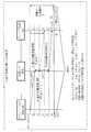
次に、図2を参照して、本実施の形態に係る時刻同期シーケンスを説明する。
なお、以下の(1)~(5)は図2の(1)~(5)に対応する。Next, a time synchronization sequence according to the present embodiment will be described with reference to FIG.
The following (1) to (5) correspond to (1) to (5) in FIG.
(1)スレーブ装置(S1)20は、グランドマスタ装置(GM)10との伝搬遅延計測(図16の(1)~(6)の手順)を繰り返し実施する。但し、図2において送受信されるDelayReqフレーム及びDelayRespフレームは、前述したように、図16に示すDelayReqフレーム及びDelayRespフレームとは異なる。
スレーブ装置(S1)20は、伝搬遅延計測において、伝搬遅延時間とスレーブカウンタのカウント値とマスタカウンタのカウント値との差を計測する。そして、スレーブ装置(S1)20は、過去の複数の伝搬遅延計測から、グランドマスタ装置(GM)10とスレーブ装置(S1)20との間の伝搬遅延時間の平均値(以下、平均伝搬遅延D_aveという)を得る。また、スレーブ装置(S1)20は、過去の複数の伝搬遅延計測から、スレーブカウンタのカウント値とマスタカウンタのカウント値の差の平均値(以下、平均カウント差C_aveという)を得る。
ここでは、以下の平均伝搬遅延D_aveと平均カウント差C_aveが得られたとする。なお、平均伝搬遅延D_aveは、過去の伝搬遅延計測から得られた伝搬遅延の値であり、計測伝搬遅延値に相当する。また、平均カウント差C_aveは、平均伝搬遅延D_aveに対応するマスタカウンタのカウント値とスレーブカウンタのカウント値との間の差であり、遅延カウント差に相当する。(1) The slave device (S1) 20 repeatedly executes propagation delay measurement (the procedure of (1) to (6) in FIG. 16) with the grand master device (GM) 10. However, as described above, the DelayReq frame and the DelayResp frame transmitted / received in FIG. 2 are different from the DelayReq frame and the DelayResp frame shown in FIG.
The slave device (S1) 20 measures the difference between the propagation delay time and the count value of the slave counter and the count value of the master counter in the propagation delay measurement. Then, the slave device (S1) 20 calculates the average value of the propagation delay time between the grand master device (GM) 10 and the slave device (S1) 20 based on a plurality of propagation delay measurements in the past (hereinafter, average propagation delay D_ave Get). Also, the slave device (S1) 20 obtains an average value (hereinafter referred to as average count difference C_ave) of the difference between the count value of the slave counter and the count value of the master counter from a plurality of propagation delay measurements in the past.
Here, it is assumed that the following average propagation delay D_ave and average count difference C_ave are obtained. The average propagation delay D_ave is a value of propagation delay obtained from past propagation delay measurement, and corresponds to a measurement propagation delay value. The average count difference C_ave is a difference between the count value of the master counter corresponding to the average propagation delay D_ave and the count value of the slave counter, and corresponds to the delay count difference.

なお、RCGM_S1は、グランドマスタ装置(GM)10のクロック周波数とスレーブ装置(S1)20のクロック周波数との比率である。
本実施の形態では、計算を単純にするために、スレーブ装置(S1)20とグランドマスタ装置(GM)10との間のクロック周波数偏差は無視できるほど小さいものとし、RCGM_S1=1と仮定する。クロック比の算出方法は、IEEE802.1ASのものと同じであるため、ここではクロック比の算出方法の説明は省略する。また、グラウンドマスタ装置(GM)10のクロック周波数を1と仮定する。RCGM_S1 is a ratio of the clock frequency of the grand master device (GM) 10 to the clock frequency of the slave device (S1) 20.
In this embodiment, in order to simplify the calculation, it is assumed that the clock frequency deviation between the slave device (S1) 20 and the grand master device (GM) 10 is negligibly small, and it is assumed that RCGM_S1 = 1. . Since the method of calculating the clock ratio is the same as that of the IEEE 802.1AS, the description of the method of calculating the clock ratio is omitted here. Further, it is assumed that the clock frequency of the ground master device (GM) 10 is one.
(2)グランドマスタ装置(GM)10は、マスタ時計のタイムスタンプT_sync=11とマスタカウンタのタイムスタンプt3=1をSyncフレームに格納し、Syncフレームをスレーブ装置(S1)20に送信する。前述したように、IEEE1588及びIEEE802.1ASでは、Syncフレームに格納されるタイムスタンプはマスタ時計のタイムスタンプT_syncのみであり、マスタカウンタのタイムスタンプt3はSyncフレームに格納されない。このように、本実施の形態に係るSyncフレームはマスタカウンタのタイムスタンプt3が格納される点で、IEEE1588及びIEEE802.1ASのSyncフレームとは異なる。
なお、以下では、Syncフレームに格納されるマスタ時計のタイムスタンプT_syncを送信時刻T_syncともいう。また、Syncフレームに格納されるマスタカウンタのタイムスタンプt3を送信カウント値t3ともいう。(2) The grand master device (GM) 10 stores the time stamp T_sync = 11 of the master clock and the time stamp t3 = 1 of the master counter in the Sync frame, and transmits the Sync frame to the slave device (S1) 20. As described above, in IEEE 1588 and IEEE 802.1AS, the time stamp stored in the Sync frame is only the master clock time stamp T_sync, and the master counter time stamp t3 is not stored in the Sync frame. Thus, the Sync frame according to the present embodiment differs from the Sync frame of IEEE 1588 and IEEE 802.1 AS in that the timestamp t3 of the master counter is stored.
Hereinafter, the time stamp T_sync of the master clock stored in the Sync frame is also referred to as transmission time T_sync. Further, the time stamp t3 of the master counter stored in the Sync frame is also referred to as a transmission count value t3.
(3)スレーブ装置(S1)20は、Syncフレームを受信する。また、スレーブ装置(S1)20は、Syncフレームの受信時点のスレーブ時計のタイムスタンプT_RX=26とスレーブカウンタのタイムスタンプt4=9を保持する。
なお、以下では、Syncフレームの受信時点でのスレーブ時計のタイムスタンプT_RXを受信時刻T_RXともいう。また、Syncフレームの受信時点でのスレーブカウンタのタイムスタンプt4を受信カウント値t4ともいう。(3) The slave device (S1) 20 receives the Sync frame. Also, the slave device (S1) 20 holds the timestamp T_RX = 26 of the slave clock and the timestamp t4 = 9 of the slave counter at the time of reception of the Sync frame.
In the following, the time stamp T_RX of the slave clock at the time of reception of the Sync frame is also referred to as a reception time T_RX. Further, the timestamp t4 of the slave counter at the time of reception of the Sync frame is also referred to as a reception count value t4.
(4)スレーブ装置(S1)20は、Syncフレームの伝搬遅延を以下にて算出する。
(a)まず、スレーブ装置(S1)20は、送信カウント値t3(=1)と受信カウント値t4(=9)との差から平均カウント差C_ave(=6)を減算して、中継遅延差Δを得る。なお、中継遅延差Δは、Syncフレームの中継の際の汎用ハブ(HUB)30による中継遅延の値と平均伝搬遅延D_aveに含まれる中継遅延の値との差である。
Δ=t4×RCGM_S1-t3-C_ave=(9-1-6)=2 式3
(b)次に、スレーブ装置(S1)20は、Syncフレームの送信での伝搬遅延D_trueを以下にて算出する。
D_true=D_ave+Δ*1/グランドマスタ装置のクロック周波数=3+2=5 式4(4) The slave device (S1) 20 calculates the propagation delay of the Sync frame as follows.
(A) First, the slave device (S1) 20 subtracts the average count difference C_ave (= 6) from the difference between the transmission count value t3 (= 1) and the reception count value t4 (= 9) to obtain a relay delay difference. Get Δ. The relay delay difference Δ is a difference between the value of the relay delay by the universal hub (HUB) 30 at the time of relaying the Sync frame and the value of the relay delay included in the average propagation delay D_ave.
Δ = t4 × RCGM_S1 -t3-C_ave = (9-1-6) = 2
(B) Next, the slave device (S1) 20 calculates the propagation delay D_true in transmission of the Sync frame as follows.
D_true = D_ave + Δ * 1/1 / Grandmaster device clock frequency = 3 + 2 = 5
(5)スレーブ装置(S1)20は、マスタ時計とスレーブ時計との時刻差をOffset(N)として算出し、Offset(N)の値を用いて、スレーブ時計の時刻を補正する。
(a)スレーブ装置(S1)20は、送信時刻T_sync(=11)と、伝搬遅延D_true(=5)と、受信時刻T_RX(=26)を用いて、以下に示すようにOffset(N)を算出する。
Offset(N)=T_sync+D_true-T_RX
=(11+5-26)=-10 式5
(b)また、スレーブ装置(S1)20は、Offset(N)の値を用いて時刻27のタイミングでスレーブ時計の時刻を以下にて補正する。
27+Offset(N)=27-10=17 式6
以上の処理により、グランドマスタ装置(GM)10のマスタ時計の時刻とスレーブ装置(S1)20のスレーブ時計の時刻が同期する。(5) The slave device (S1) 20 calculates the time difference between the master clock and the slave clock as Offset (N), and corrects the time of the slave clock using the value of Offset (N).
(A) The slave device (S1) 20 uses the transmission time T_sync (= 11), the propagation delay D_true (= 5), and the reception time T_RX (= 26) to set the Offset (N) as shown below. calculate.
Offset (N) = T_sync + D_true-T_RX
= (11 + 5-26) = -10
(B) Also, the slave device (S1) 20 corrects the time of the slave clock below at time 27 using the value of Offset (N).
27 + Offset (N) = 27-10 = 17
By the above processing, the time of the master clock of the grand master device (GM) 10 and the time of the slave clock of the slave device (S1) 20 are synchronized.
***構成の説明***
図3は、本実施の形態に係るグランドマスタ装置(GM)10のハードウェア構成例を示す。
図4は、本実施の形態に係るグランドマスタ装置(GM)10の機能構成例を示す。
本実施の形態に係るグランドマスタ装置(GM)10は、コンピュータである。*** Description of the configuration ***
FIG. 3 shows an example of the hardware configuration of the grand master device (GM) 10 according to the present embodiment.
FIG. 4 shows an example of the functional configuration of the grand master device (GM) 10 according to the present embodiment.
The grand master device (GM) 10 according to the present embodiment is a computer.
図3に示すように、グランドマスタ装置(GM)10は、ハードウェアとして、入力インタフェース101、プロセッサ102、補助記憶装置103、メモリ104、出力インタフェース105、ネットワークインタフェース111、ネットワークインタフェース112、ネットワークポート113及びネットワークポート114を備える。
また、図4に示すように、グランドマスタ装置(GM)10は、機能構成として、制御部106、時刻管理部107、時間計測部108、送信部109、データ調停部110及び受信部115を備える。
補助記憶装置103には、制御部106、時刻管理部107、時間計測部108、送信部109、データ調停部110及び受信部115の機能を実現するプログラムが記憶されている。
これらプログラムは補助記憶装置103からメモリ104にロードされる。また、プロセッサ102がこれらプログラムをメモリ104から読み出し、これらプログラムを実行する。そして、プロセッサ102は、後述する制御部106、時刻管理部107、時間計測部108、送信部109、データ調停部110及び受信部115の動作を行う。
図3では、プロセッサ102が、制御部106、時刻管理部107、時間計測部108、送信部109、データ調停部110及び受信部115の機能を実現するプログラムを実行している状態を模式的に表している。
入力インタフェース101は、グランドマスタ装置(GM)10のユーザが各種指示を入力するために用いられる。
また、メモリ104には、前述の送信時刻、送信カウント値等が格納される。
出力インタフェース105は、グランドマスタ装置(GM)10の外部記憶媒体にデータを出力するために用いられる。
ネットワークインタフェース111は、ネットワークポート113と時刻管理部107、時間計測部108又はデータ調停部110との間のフレームの転送を制御する。
ネットワークインタフェース112は、ネットワークポート114と時刻管理部107、時間計測部108又はデータ調停部110との間のフレームの転送を制御する。
ネットワークポート113及びネットワークポート114は、ネットワークとの物理的な接続口である。As shown in FIG. 3, the grand master device (GM) 10 includes, as hardware, an
Further, as shown in FIG. 4, the grand master device (GM) 10 includes, as functional components, a
The
These programs are loaded from the
In FIG. 3, the
The
The
The
The
The
The
図4において、制御部106は、グランドマスタ装置(GM)10の全体の制御を行う。
具体的には、制御部106は、受信部115がDelayReqフレームを受信した際に、DelayReqフレームの受信を時刻管理部107及び時間計測部108に通知する。
また、制御部106は、DelayRespフレームの送信を時刻管理部107、時間計測部108及び送信部109に指示する。
制御部106は、受信部115によりDelayReqフレームの受信が通知された場合に、時刻管理部107、時間計測部108及び送信部109にDelayRespフレームの送信を指示する。
また、制御部106は、Syncフレームの送信を、時刻管理部107、時間計測部108及び送信部109に指示する。制御部106は、伝搬遅延計測(図16の(1)~(6)の手順)の実施回数が設定値を超えた場合に、時刻管理部107、時間計測部108及び送信部109にSyncフレームの送信を指示する。なお、制御部106は、Syncフレームの送信周期をカウントし、指定された周期で時刻管理部107、時間計測部108及び送信部109にSyncフレームの送信を指示する。In FIG. 4, the
Specifically, when the receiving
Also, the
When reception of the DelayReq frame is notified by the
Also, the
時刻管理部107は、マスタ時計として動作する。具体的には、時刻管理部107は、時刻情報を保持する。時刻管理部107は、時間計測部108よりマスタカウンタ1080のカウントアップが通知されると時刻情報を更新する。時刻管理部107は、時間計測部108からカウントアップが通知される度にナノ秒オーダで時刻を更新する。
例えば、マスタカウンタ1080の動作クロックが125MHzの場合は、マスタカウンタ1080のカウントアップごとに、時刻管理部107は、8ナノ秒(1/125MHz=8ns)単位で時刻を更新する。
また、時刻管理部107は、制御部106からDelayReqフレームの受信が通知された場合に、現在時刻を取得し、取得した現在時刻をメモリ104に格納する。
また、時刻管理部107は、制御部106からDelayRespフレームの送信が指示された際に現在時刻を取得し、取得した現在時刻を送信部109に通知する。
また、時刻管理部107は、制御部106からSyncフレームの送信が指示された際に現在時刻を取得し、取得した現在時刻を送信部109に通知する。The
For example, when the operation clock of the master counter 1080 is 125 MHz, the
Further, when the
Further, when the transmission of a DelayResp frame is instructed from the
Further, the
時間計測部108は、フリーランカウンタであるマスタカウンタ1080を有する。マスタカウンタ1080はグランドマスタ装置(GM)10の起動時にカウントアップを開始する。また、マスタカウンタ1080の値はグランドマスタ装置(GM)10の停止時にリセットされる。
時間計測部108は、マスタカウンタ1080がカウントアップする度に、時刻管理部107にマスタカウンタ1080のカウントアップを通知する。
また、時間計測部108は、制御部106からDelayReqフレームの受信が通知された場合に、マスタカウンタ1080の現在のカウント値を取得し、取得したカウント値をメモリ104に格納する。
また、時間計測部108は、制御部106からDelayRespフレームの送信が指示された際にマスタカウンタ1080の現在のカウント値を取得し、取得したカウント値を送信部109に通知する。
また、時間計測部108は、制御部106からSyncフレームの送信が指示された際にマスタカウンタ1080の現在のカウント値を取得し、取得したカウント値を送信部109に通知する。The
The
Further, when the
Further, when the transmission of the DelayResp frame is instructed from the
Also, when instructed by the
送信部109は、制御部106からDelayRespフレームの送信が指示された場合に、DelayRespフレームを生成する。また、送信部109は、時刻管理部107から通知された現在時刻をDelayRespフレームに格納する。更に、送信部109は、時間計測部108から通知された現在のカウント値をDelayRespフレームに格納する。そして、送信部109は、現在時刻と現在のカウント値が格納されたDelayRespフレームをスレーブ装置(S1)20に送信する。より具体的には、送信部109は、DelayRespフレームをデータ調停部110に出力する。
また、送信部109は、制御部106からSyncフレームの送信が指示された場合に、Syncフレームを生成する。また、送信部109は、時刻管理部107から通知された現在時刻をSyncフレームに格納する。更に、送信部109は、時間計測部108から通知された現在のカウント値をSyncフレームに格納する。そして、送信部109は、現在時刻と現在のカウント値が格納されたSyncフレームをスレーブ装置(S1)20に送信する。より具体的には、送信部109は、Syncフレームをデータ調停部110に出力する。
なお、Syncフレームに格納される現在時刻は前述の送信時刻である。また、Syncフレームに格納される現在のカウント値は前述の送信カウント値である。The transmitting
In addition, the
The current time stored in the Sync frame is the aforementioned transmission time. Also, the current count value stored in the Sync frame is the aforementioned transmission count value.
データ調停部110は、ネットワークインタフェース111又はネットワークインタフェース112で受信された通信フレームについて、メッセージ種別の判定、正常であるか否かの判定、宛先の判定を行う。
そして、データ調停部110は、受信された通信フレームがグランドマスタ装置(GM)10宛ての通信フレームである場合は、データ調停部110は、当該通信フレームを受信部115に転送する。例えば、データ調停部110は、受信された通信フレームがDelayReqフレームであれば、DelayReqフレームを受信部115に転送する。
一方、受信された通信フレームが他の装置宛ての通信フレームである場合は、データ調停部110は、中継処理を行う。
また、データ調停部110は、送信部109から出力されたDelayRespフレーム及びSyncフレームを、ネットワークインタフェース111又はネットワークインタフェース112に出力する。The
Then, when the received communication frame is a communication frame addressed to the grand master device (GM) 10, the
On the other hand, when the received communication frame is a communication frame addressed to another device, the
Also, the
受信部115は、スレーブ装置(S1)20から送信されたDelayReqフレームを受信する。つまり、受信部115は、データ調停部110から転送されたDelayReqフレームを受信する。
また、受信部115は、DelayReqフレームを受信した場合に、制御部106にDelayReqフレームの受信を通知する。The receiving
Also, when the receiving
図4のネットワークインタフェース111、ネットワークインタフェース112、ネットワークポート113及びネットワークポート114は、図3に示したものと同じである。The
図5は、本実施の形態に係るスレーブ装置(S1)20のハードウェア構成例を示す。
図6は、本実施の形態に係るスレーブ装置(S1)20の機能構成例を示す。
本実施の形態に係るスレーブ装置(S1)20は、コンピュータである。FIG. 5 shows an example of the hardware configuration of the slave device (S1) 20 according to the present embodiment.
FIG. 6 shows an example of a functional configuration of the slave device (S1) 20 according to the present embodiment.
The slave device (S1) 20 according to the present embodiment is a computer.
図5に示すように、スレーブ装置(S1)20は、ハードウェアとして、入力インタフェース201、プロセッサ202、補助記憶装置203、メモリ204、出力インタフェース205、ネットワークインタフェース211、ネットワークインタフェース212、ネットワークポート213及びネットワークポート214を備える。
また、図6に示すように、スレーブ装置(S1)20は、機能構成として、制御部206、時刻管理部207、時間計測部208、送信部209、データ調停部210及び受信部215を備える。
補助記憶装置203には、制御部206、時刻管理部207、時間計測部208、送信部209、データ調停部210及び受信部215の機能を実現するプログラムが記憶されている。
これらプログラムは補助記憶装置203からメモリ204にロードされる。また、プロセッサ202がこれらプログラムをメモリ204から読み出し、これらプログラムを実行する。そして、プロセッサ202は、後述する制御部206、時刻管理部207、時間計測部208、送信部209、データ調停部210及び受信部215の動作を行う。
図5では、プロセッサ202が、制御部206、時刻管理部207、時間計測部208、送信部209、データ調停部210及び受信部215の機能を実現するプログラムを実行している状態を模式的に表している。
入力インタフェース201は、スレーブ装置(S1)20のユーザが各種指示を入力するために用いられる。
また、メモリ204には、前述の送信時刻、送信カウント値、受信時刻、受信カウント値、平均カウント差C_ave、平均伝搬遅延D_ave等が格納される。
出力インタフェース205は、スレーブ装置(S1)20の外部記憶媒体にデータを出力するために用いられる。
ネットワークインタフェース211は、ネットワークポート213と時刻管理部207、時間計測部208又はデータ調停部210との間のフレームの転送を制御する。
ネットワークインタフェース212は、ネットワークポート214と時刻管理部207、時間計測部208又はデータ調停部210との間のフレームの転送を制御する。
ネットワークポート213及びネットワークポート214は、ネットワークとの物理的な接続口である。As shown in FIG. 5, the slave device (S1) 20 includes, as hardware, an
Further, as shown in FIG. 6, the slave device (S1) 20 includes a
The
These programs are loaded from the
In FIG. 5, the
The
The
The
The
The
The
図6において、制御部206は、スレーブ装置(S1)20の全体の制御を行う。
具体的には、制御部206は、DelayReqフレームの送信を送信部209に指示する。また、制御部206は、DelayReqフレームの送信を時刻管理部207及び時間計測部208に通知する。
また、制御部206は、受信部215がDelayRespフレームを受信した際に、DelayRespフレームの受信を時刻管理部207及び時間計測部208に通知する。
更に、制御部206は、受信部215がSyncフレームを受信した際に、Syncフレームの受信を時刻管理部207及び時間計測部208に通知する。
また、制御部206は、時刻管理部207に時刻補正の指示を行う。In FIG. 6, the
Specifically, the
Also, when the receiving
Furthermore, when the receiving
The
時刻管理部207は、スレーブ時計として動作する。具体的には、時刻管理部207は、時刻情報を保持する。時刻管理部207は、時間計測部208よりスレーブカウンタ2080のカウントアップが通知されると時刻情報を更新する。時刻管理部207は、時間計測部208からカウントアップが通知される度にナノ秒オーダで時刻を更新する。
例えば、スレーブカウンタ2080の動作クロックが125MHzの場合は、スレーブカウンタ2080のカウントアップごとに、時刻管理部207は、8ナノ秒(1/125MHz=8ns)単位で時刻を更新する。
また、時刻管理部207は、制御部206からDelayReqフレームの送信が通知された際に現在時刻を取得し、取得した現在時刻をメモリ204に格納する。
更に、時刻管理部207は、制御部206からDelayRespフレームの受信が通知された際に現在時刻を取得し、取得した現在時刻をメモリ204に格納する。
また、時刻管理部207は、制御部206からSyncフレームの受信が通知された際に現在時刻を取得し、取得した現在時刻をメモリ204に格納する。Syncフレームの受信時の現在時刻は前述の受信時刻である。
また、時刻管理部207は、制御部206から時刻補正が指示された場合に、スレーブ時計の時刻を補正する。
時刻管理部207は、受信部215により取得された送信時刻と送信カウント値と、時間計測部208により取得された受信カウント値と、受信時刻と、計測伝搬遅延値である平均伝搬遅延D_aveと、遅延カウント差である平均カウント差C_aveとを用いて、スレーブ時計の時刻を補正する。具体的には、時刻管理部207は、前述の式3に基づき中継遅延差Δを算出し、前述の式4に基づき伝搬遅延D_trueを算出する。また、時刻管理部207は、前述の式5に基づきOffset(N)を算出する。最終的に、時刻管理部207は前述の式6に基づきスレーブ時計の時刻を補正する。
時刻管理部207は取得部及び時刻補正部に相当する。The
For example, when the operation clock of the
Further, when notified of the transmission of the DelayReq frame from the
Furthermore, when the reception of the DelayResp frame is notified from the
Further, the
Also, when time correction is instructed from the
The
The
時間計測部208は、フリーランカウンタであるスレーブカウンタ2080を有する。スレーブカウンタ2080はスレーブ装置(S1)20の起動時にカウントアップを開始する。また、スレーブカウンタ2080の値はスレーブ装置(S1)20の停止時にリセットされる。
時間計測部208は、スレーブカウンタ2080がカウントアップする度に、時刻管理部207にスレーブカウンタ2080のカウントアップを通知する。
また、時間計測部208は、制御部206からDelayReqフレームの送信が通知された際にスレーブカウンタ2080の現在のカウント値を取得し、取得したカウント値をメモリ204に格納する。
更に、時間計測部208は、制御部206からDelayRespフレームの受信が通知された際にスレーブカウンタ2080の現在のカウント値を取得し、取得したカウント値をメモリ204に格納する。
また、時間計測部208は、制御部206からSyncフレームの受信が通知された際にスレーブカウンタ2080の現在のカウント値を取得し、取得したカウント値をメモリ204に格納する。Syncフレームの受信時のカウント値は前述の受信カウント値である。
時間計測部208は時刻管理部207とともに取得部に相当する。The
Each time the
Further, when notified of the transmission of the DelayReq frame from the
Further, the
Further, when notified of the reception of the Sync frame from the
The
送信部209は、制御部206からDelayReqフレームの送信が指示された場合に、DelayReqフレームを生成する。そして、送信部209は、DelayReqフレームをグランドマスタ装置(GM)10に送信する。より具体的には、送信部209は、DelayReqフレームをデータ調停部210に出力する。The transmitting
データ調停部210は、ネットワークインタフェース211又はネットワークインタフェース212で受信された通信フレームについて、メッセージ種別の判定、正常であるか否かの判定、宛先の判定を行う。
そして、データ調停部210は、受信された通信フレームがスレーブ装置(S1)20宛ての通信フレームである場合は、データ調停部210は、当該通信フレームを受信部215に転送する。例えば、データ調停部110は、受信された通信フレームがDelayRespフレームであれば、DelayRespフレームを受信部115に転送する。また、データ調停部110は、受信された通信フレームがSyncフレームであれば、Syncフレームを受信部115に転送する。
一方、受信された通信フレームが他の装置宛ての通信フレームである場合は、データ調停部210は、中継処理を行う。
また、データ調停部210は、送信部209から出力されたDelayReqフレームを、ネットワークインタフェース211又はネットワークインタフェース212に出力する。The
Then, when the received communication frame is a communication frame addressed to the slave device (S1) 20, the
On the other hand, when the received communication frame is a communication frame addressed to another device, the
Also, the
受信部215は、グランドマスタ装置(GM)10から送信されたDelayRespフレームを受信する。つまり、受信部115は、データ調停部210から転送されたDelayRespフレームを受信する。受信部215は、受信したDelayRespフレームから、グランドマスタ装置(GM)10により格納された時刻及びカウント値を取得する。そして、受信部215は、取得した時刻及びカウント値をメモリ204に格納する。
また、受信部215は、DelayRespフレームを受信した場合に、制御部206にDelayRespフレームの受信を通知する。
更に、受信部215は、グランドマスタ装置(GM)10から送信されたSyncフレームを受信する。つまり、受信部115は、データ調停部210から転送されたSyncフレームを受信する。受信部215は、受信したSyncフレームから、グランドマスタ装置(GM)10により格納された時刻(送信時刻)及びカウント値(送信カウント値)を取得する。そして、受信部215は、取得した送信時刻及び送信カウント値をメモリ204に格納する。
また、受信部215は、Syncフレームを受信した場合に、制御部206にSyncフレームの受信を通知する。The receiving
Further, when the receiving
Furthermore, the receiving
In addition, when the receiving
図6のネットワークインタフェース211、ネットワークインタフェース212、ネットワークポート213及びネットワークポート214は、図5に示したものと同じである。The
***動作の説明***
図7はカウントアップ及び時刻計測フローを示す。
図7に示すカウントアップ及び時刻計測フローは、グランドマスタ装置(GM)10及びスレーブ装置(S1)20で共通に行われる。*** Description of operation ***
FIG. 7 shows a count up and time measurement flow.
The count-up and time measurement flow shown in FIG. 7 is commonly performed by the grand master device (GM) 10 and the slave device (S1) 20.
グランドマスタ装置(GM)10では、時間計測部108が、マスタカウンタ1080の動作クロックの立上りエッジを検出するまで待機し(ステップS101)、立上りエッジを検出したら(ステップS102でYES)、マスタカウンタ1080をカウントアップする(ステップS103)。また、時間計測部108は、時刻管理部107にマスタカウンタ1080のカウントアップを通知し、時刻管理部107は時刻を更新する(ステップS103)。
前述したように、マスタカウンタ1080の動作クロックが125MHzの場合は、マスタカウンタ1080のカウントアップごとに、時刻管理部107は、8ナノ秒(1/125MHz=8ns)単位で時刻を更新する。In the grand master device (GM) 10, the
As described above, when the operation clock of the master counter 1080 is 125 MHz, the
また、スレーブ装置(S1)20では、時間計測部208が、スレーブカウンタ2080の動作クロックの立上りエッジを検出するまで待機し(ステップS101)、立上りエッジを検出したら(ステップS102でYES)、スレーブカウンタ2080をカウントアップする(ステップS103)。また、時間計測部208は、時刻管理部207にスレーブカウンタ2080のカウントアップを通知し、時刻管理部207は時刻を更新する(ステップS103)。
前述したように、スレーブカウンタ2080の動作クロックが125MHzの場合は、スレーブカウンタ2080のカウントアップごとに、時刻管理部207は、8ナノ秒(1/125MHz=8ns)単位で時刻を更新する。In the slave device (S1) 20, the
As described above, when the operation clock of the
図8は、スレーブ装置(S1)20によるDelayReqフレームの送信フローを示す。FIG. 8 shows the transmission flow of the DelayReq frame by the slave device (S1) 20.
制御部206は、DelayReqフレームの送信タイミングが到来するのを待つ(ステップS201)。
DelayReqフレームの送信タイミングが到来すると(ステップS202でYES)、制御部206は送信部209にDelayReqフレームの送信を指示する。送信部209は、DelayReqフレームをグランドマスタ装置(GM)10に送信する(ステップS203)。
また、制御部206は、送信部209へのDelayReqフレームの送信指示に並行して時刻管理部207及び時間計測部208にDelayReqフレームの送信を通知する。時刻管理部207は、制御部206からの通知に基づき、現在時刻をDelayReqフレームの送信時刻として取得し、取得した現在時刻をメモリ204に格納する(ステップS204)。また、時間計測部208は、制御部206からの通知に基づき、スレーブカウンタ2080の現在のカウント値をDelayReqフレームの送信時のスレーブカウンタ2080のカウント値として取得し、取得したカウント値をメモリ204に格納する(ステップS204)。The
When the transmission timing of the DelayReq frame arrives (YES in step S202), the
Further, in parallel with the transmission instruction of the DelayReq frame to the
図9は、グランドマスタ装置(GM)10によるDelayReqフレームの受信フロー及びDelayRespフレームの送信フローを示す。FIG. 9 shows the reception flow of the DelayReq frame and the transmission flow of the DelayResp frame by the grand master device (GM) 10.
受信部115がDelayReqフレームの受信を待ち(ステップS301)、受信部115がDelayReqフレームを受信したら(ステップS302でYES)、時刻管理部107がDelayReqフレームの受信時刻を取得する(ステップS303)。また、時間計測部108がDelayReqフレームの受信時のマスタカウンタ1080の値を取得する(ステップS303)。より具体的には、受信部115は制御部106にDelayReqフレームの受信を通知する。制御部106は時刻管理部107及び時間計測部108にDelayReqフレームの受信を通知する。時刻管理部107は制御部106からの通知に基づき、現在時刻を取得し、取得した現在時刻をメモリ104に格納する。また、時間計測部108は制御部106からの通知に基づき、現在のマスタカウンタ1080のカウント値を取得し、取得したカウント値をメモリ104に格納する。
また、送信部109がDelayRespフレームを生成する(ステップS304)。より具体的には、制御部106は時刻管理部107、時間計測部108及び送信部109にDelayRespフレームの送信を指示する。時刻管理部107は現在時刻を取得し、取得した現在時刻を送信部109に通知する。時間計測部108はマスタカウンタ1080の現在のカウント値を取得し、取得したカウント値を送信部109に通知する。送信部109は、DelayRespフレームを生成し、生成したDelayRespフレームに、時刻管理部107から通知された時刻及び時間計測部108から通知されたカウント値を格納する。
そして、送信部109は、ステップS304で生成したDelayRespフレームをスレーブ装置(S1)20に送信する(ステップS305)。If the receiving
Also, the
Then, the
図10は、スレーブ装置(S1)20によるDelayRespフレームの受信フローを示す。FIG. 10 shows a reception flow of the DelayResp frame by the slave device (S1) 20.
受信部215がDelayRespフレームの受信を待ち(ステップS401)、受信部215がDelayRespフレームを受信したら(ステップS402でYES)、時刻管理部207がDelayRespフレームの受信時刻を取得する(ステップS403)。また、時間計測部208がDelayRespフレームの受信時のスレーブカウンタ2080の値を取得する(ステップS403)。より具体的には、受信部215は制御部206にDelayRespフレームの受信を通知する。制御部206は時刻管理部207及び時間計測部208にDelayRespフレームの受信を通知する。時刻管理部207は制御部206からの通知に基づき、現在時刻を取得し、取得した現在時刻をメモリ204に格納する。また、時間計測部208は制御部206からの通知に基づき、現在のスレーブカウンタ2080のカウント値を取得し、取得したカウント値をメモリ204に格納する。
また、受信部215は、DelayRespフレームから、DelayRespフレームの送信時刻とDelayRespフレームの送信時のマスタカウンタ1080の値を抽出する(ステップS404)。そして、受信部215は、抽出した送信時刻とマスタカウンタ1080の値をメモリ204に格納する。
なお、図10では、ステップS403の後にステップS404が行われることになっているが、ステップS403とステップS404とが並行して行われてもよい。When the
In addition, the
Although step S404 is to be performed after step S403 in FIG. 10, step S403 and step S404 may be performed in parallel.
図11は、グランドマスタ装置(GM)10によるSyncフレームの送信フローを示す。FIG. 11 shows the flow of transmission of Sync frames by the grandmaster apparatus (GM) 10.
制御部106は、Syncフレームの送信タイミングが到来するのを待つ(ステップS501)。
Syncフレームの送信タイミングが到来すると(ステップS502でYES)、制御部106は時刻管理部107、時間計測部108及び送信部109にSyncフレームの送信を指示する。時刻管理部107は、現在時刻を取得し、取得した現在時刻を送信部109に通知する(ステップS503)。また、時間計測部108は、マスタカウンタ1080の現在のカウント値を取得し、取得したカウント値を送信部109に通知する(ステップS503)。
送信部109は、Syncフレームを生成し、生成したSyncフレームに、時刻管理部107から通知された時刻及び時間計測部108から通知されたカウント値を格納する(ステップS504)。
そして、送信部109は、Syncフレームをスレーブ装置(S1)20に送信する(ステップS505)。The
When the transmission timing of the Sync frame arrives (YES in step S502), the
The transmitting
Then, the transmitting
図12は、スレーブ装置(S1)20によるSyncフレームの受信フローを示す。FIG. 12 shows the reception flow of the Sync frame by the slave device (S1) 20.
受信部215がSyncフレームの受信を待ち(ステップS601)、受信部215がSyncフレームを受信したら(ステップS602でYES)、時刻管理部207がSyncフレームの受信時刻を取得する(ステップS603)。また、時間計測部208がSyncフレームの受信時のスレーブカウンタ2080の値(受信カウント値)を取得する(ステップS603)。より具体的には、受信部215は制御部206にSyncフレームの受信を通知する。制御部206は時刻管理部207及び時間計測部208にSyncフレームの受信を通知する。時刻管理部207は制御部206からの通知に基づき、現在時刻を取得し、取得した現在時刻をメモリ204に格納する。また、時間計測部208は制御部206からの通知に基づき、スレーブカウンタ2080の現在のカウント値を取得し、取得したカウント値をメモリ204に格納する。
また、受信部215は、Syncフレームから、Syncフレームの送信時刻とSyncフレームの送信時のマスタカウンタ1080の値(送信カウント値)を抽出する(ステップS604)。そして、受信部215は、抽出した送信時刻とマスタカウンタ1080の値をメモリ204に格納する。
なお、図12では、ステップS603の後にステップS604が行われることになっているが、ステップS603とステップS604とが並行して行われてもよい。When the
Further, the receiving
In FIG. 12, step S604 is to be performed after step S603, but step S603 and step S604 may be performed in parallel.
図13は、スレーブ装置(S1)20による時刻補正フローを示す。FIG. 13 shows a time correction flow by the slave device (S1) 20.
時刻管理部207は、制御部206からの時刻補正の指示を待つ(ステップS701)。
制御部206から時刻補正が指示された場合(ステップS702でYES)に、時刻管理部207は、メモリ204に平均伝搬遅延D_aveと平均カウント差C_aveとが存在するか否かを判定する(ステップS703)。
メモリ204に平均伝搬遅延D_aveと平均カウント差C_aveが存在していなければ(ステップS703でNO)、処理はステップS701に戻る。
メモリ204に平均伝搬遅延D_aveと平均カウント差C_aveが存在していれば(ステップS703でYES)、時刻管理部207は、中継遅延差Δを算出する(ステップS704)。具体的には、時刻管理部207は、前述の式3に従って、中継遅延差Δを算出する。
次に、時刻管理部207は、伝搬遅延D_trueを算出する(ステップS705)。具体的には、時刻管理部207は、前述の式4に従って、伝搬遅延D_trueを算出する。
次に、時刻管理部207は、Offset(N)を算出する(ステップS706)。具体的には、時刻管理部207は、前述の式5に従って、Offset(N)を算出する。
最後に、時刻管理部207は、Offset(N)を用いてスレーブ時計の時刻を補正する(ステップS707)。具体的には、時刻管理部207は、前述の式6に従って、時刻を補正する。The
When time correction is instructed from control unit 206 (YES in step S702),
If the average propagation delay D_ave and the average count difference C_ave do not exist in the memory 204 (NO in step S703), the process returns to step S701.
If the average propagation delay D_ave and the average count difference C_ave exist in the memory 204 (YES in step S703), the
Next, the
Next, the
Finally, the
***実施の形態の効果の説明***
以上のように、本実施の形態によれば、伝送路での遅延時間の揺らぎにより発生するグランドマスタ装置(GM)10とスレーブ装置(S1)20との間の時刻差を補正することが可能である。つまり、本実施の形態によれば、時刻同期非対応のスイッチングハブをネットワークに混在させても、グランドマスタ装置(GM)10とスレーブ装置(S1)20との間で正確な時刻同期を実現することができる。*** Description of the effects of the embodiment ***
As described above, according to the present embodiment, it is possible to correct the time difference between the grand master device (GM) 10 and the slave device (S1) 20 generated due to the fluctuation of the delay time in the transmission path. It is. That is, according to the present embodiment, accurate time synchronization is realized between the grand master device (GM) 10 and the slave device (S1) 20 even if switching hubs incompatible with time synchronization are mixed in the network. be able to.
***ハードウェア構成の説明***
最後に、ハードウェア構成の補足説明を行う。
図3に示すプロセッサ102及び図5に示すプロセッサ202は、それぞれ、プロセッシングを行うIC(Integrated Circuit)である。
プロセッサ102及びプロセッサ202は、それぞれ、CPU(Central Processing Unit)、DSP(Digital Signal Processor)等である。
図3に示すメモリ104及び図5に示すメモリ204は、それぞれ、RAM(Random Access Memory)である。
図3に示す補助記憶装置103及び図5に示す補助記憶装置203は、それぞれ、ROM(Read Only Memory)、フラッシュメモリ、HDD(Hard Disk Drive)等である。
図3に示すネットワークインタフェース111、ネットワークインタフェース112、図5に示すネットワークインタフェース211、ネットワークインタフェース212は、それぞれ、データを受信するレシーバー及びデータを送信するトランスミッターを含む。
ネットワークインタフェース111、ネットワークインタフェース112、ネットワークインタフェース211、ネットワークインタフェース212は、それぞれ、例えば、通信チップ又はNIC(Network Interface Card)である。*** Description of hardware configuration ***
Finally, a supplementary explanation of the hardware configuration is given.
The
The
The
The
The
The
また、補助記憶装置103には、OS(Operating System)も記憶されている。
そして、OSの少なくとも一部がプロセッサ102により実行される。
プロセッサ102はOSの少なくとも一部を実行しながら、制御部106、時刻管理部107、時間計測部108、送信部109、データ調停部110及び受信部115の機能を実現するプログラムを実行する。
プロセッサ102がOSを実行することで、タスク管理、メモリ管理、ファイル管理、通信制御等が行われる。The
Then, at least part of the OS is executed by the
The
The
また、補助記憶装置203には、OS(Operating System)も記憶されている。
そして、OSの少なくとも一部がプロセッサ202により実行される。
プロセッサ202はOSの少なくとも一部を実行しながら、制御部206、時刻管理部207、時間計測部208、送信部209、データ調停部210及び受信部215の機能を実現するプログラムを実行する。
プロセッサ202がOSを実行することで、タスク管理、メモリ管理、ファイル管理、通信制御等が行われる。The
Then, at least part of the OS is executed by the
The
When the
また、制御部106、時刻管理部107、時間計測部108、送信部109、データ調停部110及び受信部115の処理の結果を示す情報、データ、信号値及び変数値の少なくともいずれかが、補助記憶装置103、メモリ104、プロセッサ102内のレジスタ及びキャッシュメモリの少なくともいずれかに記憶される。
また、制御部106、時刻管理部107、時間計測部108、送信部109、データ調停部110及び受信部115の機能を実現するプログラムは、磁気ディスク、フレキシブルディスク、光ディスク、コンパクトディスク、ブルーレイ(登録商標)ディスク、DVD等の可搬記憶媒体に記憶されてもよい。In addition, at least one of information, data, a signal value, and a variable value indicating the result of processing of
The programs for realizing the functions of the
また、制御部206、時刻管理部207、時間計測部208、送信部209、データ調停部210及び受信部215の処理の結果を示す情報、データ、信号値及び変数値の少なくともいずれかが、補助記憶装置203、メモリ204、プロセッサ202内のレジスタ及びキャッシュメモリの少なくともいずれかに記憶される。
また、制御部206、時刻管理部207、時間計測部208、送信部209、データ調停部210及び受信部215の機能を実現するプログラムは、磁気ディスク、フレキシブルディスク、光ディスク、コンパクトディスク、ブルーレイ(登録商標)ディスク、DVD等の可搬記憶媒体に記憶されてもよい。In addition, at least one of information, data, signal value, and variable value indicating the result of processing of
Also, programs for realizing the functions of the
また、制御部106、時刻管理部107、時間計測部108、送信部109、データ調停部110及び受信部115の「部」を、「回路」又は「工程」又は「手順」又は「処理」に読み替えてもよい。
また、グランドマスタ装置(GM)10は、ロジックIC(Integrated Circuit)、GA(Gate Array)、ASIC(Application Specific Integrated Circuit)、FPGA(Field-Programmable Gate Array)といった処理回路により実現されてもよい。In addition, “units” of the
Further, the grand master device (GM) 10 may be realized by a processing circuit such as a logic integrated circuit (IC), a gate array (GA), an application specific integrated circuit (ASIC), or a field-programmable gate array (FPGA).
また、制御部206、時刻管理部207、時間計測部208、送信部209、データ調停部210及び受信部215の「部」を、「回路」又は「工程」又は「手順」又は「処理」に読み替えてもよい。
また、スレーブ装置(S1)20は、ロジックIC、GA、ASIC、FPGAといった処理回路により実現されてもよい。In addition, “units” of the
Also, the slave device (S1) 20 may be realized by a processing circuit such as a logic IC, a GA, an ASIC, or an FPGA.
なお、本明細書では、プロセッサと、メモリと、プロセッサとメモリの組合せと、処理回路との上位概念を、「プロセッシングサーキットリー」という。
つまり、プロセッサと、メモリと、プロセッサとメモリの組合せと、処理回路とは、それぞれ「プロセッシングサーキットリー」の具体例である。Note that, in this specification, the upper concept of the processor, the memory, the combination of the processor and the memory, and the processing circuit is referred to as "processing circuit".
That is, the processor, the memory, the combination of the processor and the memory, and the processing circuit are specific examples of the "processing circuit".
10 グランドマスタ装置(GM)、20 スレーブ装置(S1)、30 汎用ハブ(HUB)、101 入力インタフェース、102 プロセッサ、103 補助記憶装置、104 メモリ、105 出力インタフェース、106 制御部、107 時刻管理部、108 時間計測部、109 送信部、110 データ調停部、111 ネットワークインタフェース、112 ネットワークインタフェース、113 ネットワークポート、114 ネットワークポート、115 受信部、201 入力インタフェース、202 プロセッサ、203 補助記憶装置、204 メモリ、205 出力インタフェース、206 制御部、207 時刻管理部、208 時間計測部、209 送信部、210 データ調停部、211 ネットワークインタフェース、212 ネットワークインタフェース、213 ネットワークポート、214 ネットワークポート、215 受信部、1080 マスタカウンタ、2080 スレーブカウンタ。10 Grand Master Device (GM), 20 Slave Device (S1), 30 General Purpose Hub (HUB), 101 Input Interface, 102 Processor, 103 Auxiliary Storage Device, 104 Memory, 105 Output Interface, 106 Control Unit, 107 Time Management Unit, 108 time measurement unit, 109 transmission unit, 110 data arbitration unit, 111 network interface, 112 network interface, 113 network port, 114 network port, 115 reception unit, 201 input interface, 202 processor, 203 auxiliary storage device, 204 memory, 205 Output interface, 206 control unit, 207 time management unit, 208 time measurement unit, 209 transmission unit, 210 data arbitration unit, 211 network Click interface, 212 network interface, 213 network port, 214 network ports, 215 receiving unit, 1080 a master counter, 2080 slave counter.
Claims (15)
Translated fromJapanese前記マスタ装置は、
フリーランカウンタであるマスタカウンタと、
時刻同期のための時刻同期フレームを送信するタイミングで、現在時刻を前記時刻同期フレームの送信時刻として取得し、前記マスタカウンタのカウント値を送信カウント値として取得し、前記送信時刻と前記送信カウント値とを前記時刻同期フレームに格納し、前記時刻同期フレームを前記スレーブ装置に送信する送信部とを有し、
前記スレーブ装置は、
フリーランカウンタであるスレーブカウンタと、
前記時刻同期フレームを受信する受信部と、
前記時刻同期フレームの受信時刻と、前記受信時刻における前記スレーブカウンタのカウント値である受信カウント値とを取得する取得部と、
前記送信時刻と前記送信カウント値と前記受信時刻と前記受信カウント値と、過去の計測から得られた伝搬遅延の値である計測伝搬遅延値と、前記計測伝搬遅延値に対応する前記マスタカウンタのカウント値と前記スレーブカウンタのカウント値とから求められる遅延カウント差とを用いて、前記スレーブ装置の時刻を補正する時刻補正部とを有する通信システム。It has a master device and a slave device connected via a relay device whose relay delay is not constant,
The master device is
A master counter which is a free run counter,
At the timing of transmitting a time synchronization frame for time synchronization, the current time is acquired as the transmission time of the time synchronization frame, the count value of the master counter is acquired as the transmission count value, and the transmission time and the transmission count value And a transmitter configured to store the time synchronization frame in the time synchronization frame, and transmitting the time synchronization frame to the slave device;
The slave device is
A slave counter which is a free run counter,
A receiving unit that receives the time synchronization frame;
An acquisition unit that acquires a reception time of the time synchronization frame and a reception count value that is a count value of the slave counter at the reception time;
The transmission time, the transmission count value, the reception time, the reception count value, a measurement propagation delay value that is a value of propagation delay obtained from past measurement, and the master counter corresponding to the measurement propagation delay value And a time correction unit that corrects the time of the slave device using a count value and a delay count difference obtained from the count value of the slave counter.
前記送信カウント値と前記受信カウント値と前記遅延カウント差とに基づき、前記時刻同期フレームの中継の際の前記中継装置による中継遅延の値と前記計測伝搬遅延値に含まれる中継遅延の値との差を中継遅延差として算出し、
算出した前記中継遅延差を用いて、前記スレーブ装置の時刻を補正する請求項1に記載の通信システム。The time correction unit
Based on the transmission count value, the reception count value, and the delay count difference, a value of relay delay by the relay apparatus at the time of relay of the time synchronization frame and a value of relay delay included in the measurement propagation delay value Calculate the difference as relay delay difference,
The communication system according to claim 1, wherein the time of the slave device is corrected using the calculated relay delay difference.
前記中継遅延差と前記計測伝搬遅延値とを用いて、前記時刻同期フレームの送信での伝搬遅延の値を算出し、
算出した前記時刻同期フレームの送信での伝搬遅延の値を用いて、前記スレーブ装置の時刻を補正する請求項2に記載の通信システム。The time correction unit
Calculating a value of propagation delay in transmission of the time synchronization frame using the relay delay difference and the measured propagation delay value;
The communication system according to claim 2, wherein the time of the slave device is corrected using the calculated value of the propagation delay in the transmission of the time synchronization frame.
算出した前記時刻同期フレームの送信での伝搬遅延の値と前記送信時刻と前記受信時刻とを用いて、前記マスタ装置の時刻と前記スレーブ装置の時刻との差をオフセット値として算出し、
算出した前記オフセット値を用いて、前記スレーブ装置の時刻を補正する請求項1に記載の通信システム。The time correction unit
The difference between the time of the master device and the time of the slave device is calculated as an offset value using the calculated propagation delay value in the transmission of the time synchronization frame, the transmission time, and the reception time.
The communication system according to claim 1, wherein the time of the slave device is corrected using the calculated offset value.
前記送信カウント値と前記受信カウント値と前記遅延カウント差と、前記マスタ装置のクロック周波数と前記スレーブ装置のクロック周波数とに基づき、前記中継遅延差を算出する請求項2に記載の通信システム。The time correction unit
The communication system according to claim 2, wherein the relay delay difference is calculated based on the transmission count value, the reception count value, the delay count difference, a clock frequency of the master device, and a clock frequency of the slave device.
前記計測伝搬遅延値として、過去の複数の計測において得られた複数の伝搬遅延の値の平均値を用いて、前記スレーブ装置の時刻を補正する請求項1に記載の通信システム。The time correction unit
The communication system according to claim 1, wherein the time of the slave device is corrected using an average value of a plurality of propagation delay values obtained in a plurality of past measurements as the measurement propagation delay value.
前記マスタ装置との間でフレームを送受信して計測された前記複数の伝搬遅延の値の平均値を、前記計測伝搬遅延値として用いる請求項6に記載の通信システム。The time correction unit
The communication system according to claim 6, wherein an average value of the plurality of propagation delay values measured by transmitting and receiving a frame to and from the master device is used as the measurement propagation delay value.
フリーランカウンタであるマスタカウンタと、
時刻同期のための時刻同期フレームを送信するタイミングで、現在時刻を前記時刻同期フレームの送信時刻として取得し、前記マスタカウンタのカウント値を送信カウント値として取得し、前記送信時刻と前記送信カウント値とを前記時刻同期フレームに格納し、前記送信時刻と前記送信カウント値とが格納された前記時刻同期フレームを前記スレーブ装置に送信する送信部とを有するマスタ装置。A master device connected to a slave device via a relay device whose relay delay is not constant,
A master counter which is a free run counter,
At the timing of transmitting a time synchronization frame for time synchronization, the current time is acquired as the transmission time of the time synchronization frame, the count value of the master counter is acquired as the transmission count value, and the transmission time and the transmission count value And a transmitter configured to store the time synchronization frame in which the transmission time and the transmission count value are stored, to the slave device.
中継遅延が一定でない中継装置を介して、接続されているスレーブ装置であって、
フリーランカウンタであるスレーブカウンタと、
前記マスタ装置から送信された前記時刻同期フレームを受信する受信部と、
前記時刻同期フレームの受信時刻と、前記受信時刻における前記スレーブカウンタのカウント値である受信カウント値とを取得する取得部と、
前記送信時刻と前記送信カウント値と前記受信時刻と前記受信カウント値と、過去の計測から得られた伝搬遅延の値である計測伝搬遅延値と、前記計測伝搬遅延値に対応する前記マスタカウンタのカウント値と前記スレーブカウンタのカウント値とから求められる遅延カウント差とを用いて、前記スレーブ装置の時刻を補正する時刻補正部とを有するスレーブ装置。At the timing of transmitting a time synchronization frame for time synchronization, having a master counter which is a free run counter, the current time is acquired as the transmission time of the time synchronization frame, and the count value of the master counter is used as a transmission count value. A master apparatus that acquires, stores the transmission time and the transmission count value in the time synchronization frame, and transmits the time synchronization frame in which the transmission time and the transmission count value are stored;
A slave device connected via a relay device whose relay delay is not constant,
A slave counter which is a free run counter,
A receiving unit that receives the time synchronization frame transmitted from the master device;
An acquisition unit that acquires a reception time of the time synchronization frame and a reception count value that is a count value of the slave counter at the reception time;
The transmission time, the transmission count value, the reception time, the reception count value, a measurement propagation delay value that is a value of propagation delay obtained from past measurement, and the master counter corresponding to the measurement propagation delay value A slave device, comprising: a time correction unit that corrects the time of the slave device using a count value and a delay count difference obtained from the count value of the slave counter.
前記送信カウント値と前記受信カウント値と前記遅延カウント差とに基づき、前記時刻同期フレームの中継の際の前記中継装置による中継遅延の値と前記計測伝搬遅延値に含まれる中継遅延の値との差を中継遅延差として算出し、
算出した前記中継遅延差を用いて、前記スレーブ装置の時刻を補正する請求項9に記載のスレーブ装置。The time correction unit
Based on the transmission count value, the reception count value, and the delay count difference, a value of relay delay by the relay apparatus at the time of relay of the time synchronization frame and a value of relay delay included in the measurement propagation delay value Calculate the difference as relay delay difference,
The slave device according to claim 9, wherein the time of the slave device is corrected using the calculated relay delay difference.
前記中継遅延差と前記計測伝搬遅延値とを用いて、前記時刻同期フレームの送信での伝搬遅延の値を算出し、
算出した前記時刻同期フレームの送信での伝搬遅延の値を用いて、前記スレーブ装置の時刻を補正する請求項10に記載のスレーブ装置。The time correction unit
Calculating a value of propagation delay in transmission of the time synchronization frame using the relay delay difference and the measured propagation delay value;
11. The slave device according to claim 10, wherein the time of the slave device is corrected using the calculated value of the propagation delay in the transmission of the time synchronization frame.
算出した前記時刻同期フレームの送信での伝搬遅延の値と前記送信時刻と前記受信時刻とを用いて、前記マスタ装置の時刻と前記スレーブ装置の時刻との差をオフセット値として算出し、
算出した前記オフセット値を用いて、前記スレーブ装置の時刻を補正する請求項9に記載のスレーブ装置。The time correction unit
The difference between the time of the master device and the time of the slave device is calculated as an offset value using the calculated propagation delay value in the transmission of the time synchronization frame, the transmission time, and the reception time.
The slave device according to claim 9, wherein the time of the slave device is corrected using the calculated offset value.
前記送信カウント値と前記受信カウント値と前記遅延カウント差と、前記マスタ装置のクロック周波数と前記スレーブ装置のクロック周波数とに基づき、前記中継遅延差を算出する請求項10に記載のスレーブ装置。The time correction unit
The slave device according to claim 10, wherein the relay delay difference is calculated based on the transmission count value, the reception count value, the delay count difference, a clock frequency of the master device, and a clock frequency of the slave device.
前記計測伝搬遅延値として、過去の複数の計測において得られた複数の伝搬遅延の値の平均値を用いて、前記スレーブ装置の時刻を補正する請求項9に記載のスレーブ装置。The time correction unit
The slave device according to claim 9, wherein the time of the slave device is corrected using an average value of a plurality of propagation delay values obtained in a plurality of past measurements as the measurement propagation delay value.
前記マスタ装置との間でフレームを送受信して計測された前記複数の伝搬遅延の値の平均値を、前記計測伝搬遅延値として用いる請求項14に記載のスレーブ装置。The time correction unit
The slave device according to claim 14, wherein an average value of the plurality of propagation delay values measured by transmitting and receiving a frame to and from the master device is used as the measurement propagation delay value.
Priority Applications (7)
| Application Number | Priority Date | Filing Date | Title |
|---|---|---|---|
| JP2017566875AJP6351889B1 (en) | 2017-06-27 | 2017-06-27 | Communication system and slave device |
| DE112017007691.9TDE112017007691T5 (en) | 2017-06-27 | 2017-06-27 | Communication system, master device and slave device |
| KR1020197037223AKR102103698B1 (en) | 2017-06-27 | 2017-06-27 | Communication system and slave device |
| PCT/JP2017/023645WO2019003320A1 (en) | 2017-06-27 | 2017-06-27 | Communication system, master device and slave device |
| CN201780092391.6ACN110800246A (en) | 2017-06-27 | 2017-06-27 | Communication system, master device and slave device |
| US16/607,397US20210281339A1 (en) | 2017-06-27 | 2017-06-27 | Communication system and slave device |
| TW106134693ATWI651945B (en) | 2017-06-27 | 2017-10-11 | Communication system and slave device |
Applications Claiming Priority (1)
| Application Number | Priority Date | Filing Date | Title |
|---|---|---|---|
| PCT/JP2017/023645WO2019003320A1 (en) | 2017-06-27 | 2017-06-27 | Communication system, master device and slave device |
Publications (1)
| Publication Number | Publication Date |
|---|---|
| WO2019003320A1true WO2019003320A1 (en) | 2019-01-03 |
Family
ID=62779842
Family Applications (1)
| Application Number | Title | Priority Date | Filing Date |
|---|---|---|---|
| PCT/JP2017/023645CeasedWO2019003320A1 (en) | 2017-06-27 | 2017-06-27 | Communication system, master device and slave device |
Country Status (7)
| Country | Link |
|---|---|
| US (1) | US20210281339A1 (en) |
| JP (1) | JP6351889B1 (en) |
| KR (1) | KR102103698B1 (en) |
| CN (1) | CN110800246A (en) |
| DE (1) | DE112017007691T5 (en) |
| TW (1) | TWI651945B (en) |
| WO (1) | WO2019003320A1 (en) |
Cited By (3)
| Publication number | Priority date | Publication date | Assignee | Title |
|---|---|---|---|---|
| CN113574827A (en)* | 2019-03-18 | 2021-10-29 | 三菱电机株式会社 | Time synchronization device, communication system, time synchronization method and time synchronization program |
| JP2021190849A (en)* | 2020-05-29 | 2021-12-13 | 株式会社タムラ製作所 | Information communication system and information communication device |
| WO2022019161A1 (en)* | 2020-07-22 | 2022-01-27 | 株式会社日立国際電気 | Wireless communication system |
Families Citing this family (5)
| Publication number | Priority date | Publication date | Assignee | Title |
|---|---|---|---|---|
| JP6973427B2 (en)* | 2019-02-15 | 2021-11-24 | 株式会社安川電機 | Communication systems, communication methods, and programs |
| DE112020006988B4 (en)* | 2020-05-29 | 2024-01-18 | Mitsubishi Electric Corporation | TIME CORRECTION DEVICE, TIME CORRECTION METHOD, AND TIME CORRECTION PROGRAM |
| JP7243695B2 (en)* | 2020-08-25 | 2023-03-22 | 横河電機株式会社 | Information processing device, information processing system, and information processing method |
| JP7608091B2 (en)* | 2020-08-25 | 2025-01-06 | 株式会社オートネットワーク技術研究所 | On-vehicle device, abnormality detection method, and abnormality detection program |
| CN114285512B (en)* | 2021-11-17 | 2024-01-23 | 中国电子科技集团公司第五十四研究所 | Communication timing method, communication system and communication equipment |
Citations (2)
| Publication number | Priority date | Publication date | Assignee | Title |
|---|---|---|---|---|
| WO2014203449A1 (en)* | 2013-06-18 | 2014-12-24 | 日本電気株式会社 | Communication system, method for controlling communication system, transmission device, and reception device |
| JP2017098694A (en)* | 2015-11-20 | 2017-06-01 | 富士通株式会社 | Communication device and time synchronization method thereof |
Family Cites Families (4)
| Publication number | Priority date | Publication date | Assignee | Title |
|---|---|---|---|---|
| JP2008262292A (en) | 2007-04-10 | 2008-10-30 | Hitachi Ltd | Server and local terminal group time synchronization method |
| JP5815155B2 (en)* | 2013-02-27 | 2015-11-17 | 三菱電機株式会社 | Relay device, relay method, and relay program |
| US9882705B2 (en)* | 2014-05-23 | 2018-01-30 | Mitsubishi Electric Corporation | Communication apparatus, communication method, and computer readable medium using propagation delay for time synchronization |
| KR101863022B1 (en)* | 2015-03-19 | 2018-05-30 | 미쓰비시덴키 가부시키가이샤 | Communication devices and network systems |
- 2017
- 2017-06-27KRKR1020197037223Apatent/KR102103698B1/ennot_activeExpired - Fee Related
- 2017-06-27DEDE112017007691.9Tpatent/DE112017007691T5/ennot_activeCeased
- 2017-06-27USUS16/607,397patent/US20210281339A1/ennot_activeAbandoned
- 2017-06-27CNCN201780092391.6Apatent/CN110800246A/ennot_activeWithdrawn
- 2017-06-27JPJP2017566875Apatent/JP6351889B1/ennot_activeExpired - Fee Related
- 2017-06-27WOPCT/JP2017/023645patent/WO2019003320A1/ennot_activeCeased
- 2017-10-11TWTW106134693Apatent/TWI651945B/ennot_activeIP Right Cessation
Patent Citations (2)
| Publication number | Priority date | Publication date | Assignee | Title |
|---|---|---|---|---|
| WO2014203449A1 (en)* | 2013-06-18 | 2014-12-24 | 日本電気株式会社 | Communication system, method for controlling communication system, transmission device, and reception device |
| JP2017098694A (en)* | 2015-11-20 | 2017-06-01 | 富士通株式会社 | Communication device and time synchronization method thereof |
Cited By (5)
| Publication number | Priority date | Publication date | Assignee | Title |
|---|---|---|---|---|
| CN113574827A (en)* | 2019-03-18 | 2021-10-29 | 三菱电机株式会社 | Time synchronization device, communication system, time synchronization method and time synchronization program |
| JP2021190849A (en)* | 2020-05-29 | 2021-12-13 | 株式会社タムラ製作所 | Information communication system and information communication device |
| JP7161505B2 (en) | 2020-05-29 | 2022-10-26 | 株式会社タムラ製作所 | Information communication system and information communication device |
| WO2022019161A1 (en)* | 2020-07-22 | 2022-01-27 | 株式会社日立国際電気 | Wireless communication system |
| JP7525320B2 (en) | 2020-07-22 | 2024-07-30 | 株式会社日立国際電気 | Wireless communication system |
Also Published As
| Publication number | Publication date |
|---|---|
| DE112017007691T5 (en) | 2020-03-05 |
| TW201906343A (en) | 2019-02-01 |
| CN110800246A (en) | 2020-02-14 |
| JP6351889B1 (en) | 2018-07-04 |
| TWI651945B (en) | 2019-02-21 |
| KR20200003213A (en) | 2020-01-08 |
| JPWO2019003320A1 (en) | 2019-07-04 |
| US20210281339A1 (en) | 2021-09-09 |
| KR102103698B1 (en) | 2020-04-23 |
Similar Documents
| Publication | Publication Date | Title |
|---|---|---|
| JP6351889B1 (en) | Communication system and slave device | |
| EP3202062B1 (en) | Distribution of dynamic accuracy information in a network of ieee 1588 clocks | |
| KR102031268B1 (en) | Method and apparatus for communicating time information between time-aware devices | |
| US8738792B2 (en) | Server time protocol messages and methods | |
| US8370675B2 (en) | Precise clock synchronization | |
| CN113328820B (en) | Method for interacting time synchronization message and network device | |
| EP4044466B1 (en) | Synchronization method and device | |
| US11456849B2 (en) | Method and apparatus for synchronizing different communication ports | |
| CN112162591B (en) | Electronic device with multiple processors and synchronization method thereof | |
| CN113055113B (en) | Clock time synchronization method, device, equipment and storage medium | |
| JP6227888B2 (en) | Communication system, synchronization system, and communication method | |
| EP3915207A1 (en) | Systems and methods for testing time distribution | |
| JP4931108B2 (en) | High-precision time synchronization processing device and program thereof, and network congestion level warning device and program thereof | |
| WO2022176026A1 (en) | Network translator and device translator | |
| US20170117980A1 (en) | Time synchronization for network device | |
| US20160359609A1 (en) | Communication device, communication system, estimation method, and computer program product | |
| CN118233037A (en) | Communication device, control method thereof, and storage medium | |
| TWM498417U (en) | Power management system with automatic clock synchronization function | |
| TW201626684A (en) | Electric energy management system with automatic time correction |
Legal Events
| Date | Code | Title | Description |
|---|---|---|---|
| ENP | Entry into the national phase | Ref document number:2017566875 Country of ref document:JP Kind code of ref document:A | |
| 121 | Ep: the epo has been informed by wipo that ep was designated in this application | Ref document number:17915429 Country of ref document:EP Kind code of ref document:A1 | |
| ENP | Entry into the national phase | Ref document number:20197037223 Country of ref document:KR Kind code of ref document:A | |
| 122 | Ep: pct application non-entry in european phase | Ref document number:17915429 Country of ref document:EP Kind code of ref document:A1 |