WO2019003307A1 - Surgical tool - Google Patents
Surgical toolDownload PDFInfo
- Publication number
- WO2019003307A1 WO2019003307A1PCT/JP2017/023595JP2017023595WWO2019003307A1WO 2019003307 A1WO2019003307 A1WO 2019003307A1JP 2017023595 WJP2017023595 WJP 2017023595WWO 2019003307 A1WO2019003307 A1WO 2019003307A1
- Authority
- WO
- WIPO (PCT)
- Prior art keywords
- supply state
- drive shaft
- treatment
- spring
- state
- Prior art date
- Legal status (The legal status is an assumption and is not a legal conclusion. Google has not performed a legal analysis and makes no representation as to the accuracy of the status listed.)
- Ceased
Links
Images


Classifications
- A—HUMAN NECESSITIES
- A61—MEDICAL OR VETERINARY SCIENCE; HYGIENE
- A61B—DIAGNOSIS; SURGERY; IDENTIFICATION
- A61B18/00—Surgical instruments, devices or methods for transferring non-mechanical forms of energy to or from the body
- A61B18/04—Surgical instruments, devices or methods for transferring non-mechanical forms of energy to or from the body by heating
- A61B18/08—Surgical instruments, devices or methods for transferring non-mechanical forms of energy to or from the body by heating by means of electrically-heated probes
- A61B18/082—Probes or electrodes therefor
- A61B18/085—Forceps, scissors
- A—HUMAN NECESSITIES
- A61—MEDICAL OR VETERINARY SCIENCE; HYGIENE
- A61B—DIAGNOSIS; SURGERY; IDENTIFICATION
- A61B17/00—Surgical instruments, devices or methods
- A61B17/32—Surgical cutting instruments
- A61B17/320068—Surgical cutting instruments using mechanical vibrations, e.g. ultrasonic
- A61B17/320092—Surgical cutting instruments using mechanical vibrations, e.g. ultrasonic with additional movable means for clamping or cutting tissue, e.g. with a pivoting jaw
- A—HUMAN NECESSITIES
- A61—MEDICAL OR VETERINARY SCIENCE; HYGIENE
- A61B—DIAGNOSIS; SURGERY; IDENTIFICATION
- A61B18/00—Surgical instruments, devices or methods for transferring non-mechanical forms of energy to or from the body
- A61B18/04—Surgical instruments, devices or methods for transferring non-mechanical forms of energy to or from the body by heating
- A61B18/12—Surgical instruments, devices or methods for transferring non-mechanical forms of energy to or from the body by heating by passing a current through the tissue to be heated, e.g. high-frequency current
- A61B18/14—Probes or electrodes therefor
- A61B18/1442—Probes having pivoting end effectors, e.g. forceps
- A61B18/1445—Probes having pivoting end effectors, e.g. forceps at the distal end of a shaft, e.g. forceps or scissors at the end of a rigid rod
- A—HUMAN NECESSITIES
- A61—MEDICAL OR VETERINARY SCIENCE; HYGIENE
- A61B—DIAGNOSIS; SURGERY; IDENTIFICATION
- A61B17/00—Surgical instruments, devices or methods
- A61B17/28—Surgical forceps
- A61B17/29—Forceps for use in minimally invasive surgery
- A61B17/2909—Handles
- A—HUMAN NECESSITIES
- A61—MEDICAL OR VETERINARY SCIENCE; HYGIENE
- A61B—DIAGNOSIS; SURGERY; IDENTIFICATION
- A61B17/00—Surgical instruments, devices or methods
- A61B2017/00367—Details of actuation of instruments, e.g. relations between pushing buttons, or the like, and activation of the tool, working tip, or the like
- A—HUMAN NECESSITIES
- A61—MEDICAL OR VETERINARY SCIENCE; HYGIENE
- A61B—DIAGNOSIS; SURGERY; IDENTIFICATION
- A61B18/00—Surgical instruments, devices or methods for transferring non-mechanical forms of energy to or from the body
- A61B2018/00315—Surgical instruments, devices or methods for transferring non-mechanical forms of energy to or from the body for treatment of particular body parts
- A61B2018/00345—Vascular system
- A—HUMAN NECESSITIES
- A61—MEDICAL OR VETERINARY SCIENCE; HYGIENE
- A61B—DIAGNOSIS; SURGERY; IDENTIFICATION
- A61B18/00—Surgical instruments, devices or methods for transferring non-mechanical forms of energy to or from the body
- A61B2018/00571—Surgical instruments, devices or methods for transferring non-mechanical forms of energy to or from the body for achieving a particular surgical effect
- A61B2018/00589—Coagulation
- A—HUMAN NECESSITIES
- A61—MEDICAL OR VETERINARY SCIENCE; HYGIENE
- A61B—DIAGNOSIS; SURGERY; IDENTIFICATION
- A61B18/00—Surgical instruments, devices or methods for transferring non-mechanical forms of energy to or from the body
- A61B2018/00571—Surgical instruments, devices or methods for transferring non-mechanical forms of energy to or from the body for achieving a particular surgical effect
- A61B2018/00601—Cutting
- A—HUMAN NECESSITIES
- A61—MEDICAL OR VETERINARY SCIENCE; HYGIENE
- A61B—DIAGNOSIS; SURGERY; IDENTIFICATION
- A61B18/00—Surgical instruments, devices or methods for transferring non-mechanical forms of energy to or from the body
- A61B2018/00571—Surgical instruments, devices or methods for transferring non-mechanical forms of energy to or from the body for achieving a particular surgical effect
- A61B2018/00607—Coagulation and cutting with the same instrument
- A—HUMAN NECESSITIES
- A61—MEDICAL OR VETERINARY SCIENCE; HYGIENE
- A61B—DIAGNOSIS; SURGERY; IDENTIFICATION
- A61B18/00—Surgical instruments, devices or methods for transferring non-mechanical forms of energy to or from the body
- A61B2018/00571—Surgical instruments, devices or methods for transferring non-mechanical forms of energy to or from the body for achieving a particular surgical effect
- A61B2018/0063—Sealing
- A—HUMAN NECESSITIES
- A61—MEDICAL OR VETERINARY SCIENCE; HYGIENE
- A61B—DIAGNOSIS; SURGERY; IDENTIFICATION
- A61B18/00—Surgical instruments, devices or methods for transferring non-mechanical forms of energy to or from the body
- A61B2018/00994—Surgical instruments, devices or methods for transferring non-mechanical forms of energy to or from the body combining two or more different kinds of non-mechanical energy or combining one or more non-mechanical energies with ultrasound
- A—HUMAN NECESSITIES
- A61—MEDICAL OR VETERINARY SCIENCE; HYGIENE
- A61B—DIAGNOSIS; SURGERY; IDENTIFICATION
- A61B18/00—Surgical instruments, devices or methods for transferring non-mechanical forms of energy to or from the body
- A61B18/04—Surgical instruments, devices or methods for transferring non-mechanical forms of energy to or from the body by heating
- A61B18/12—Surgical instruments, devices or methods for transferring non-mechanical forms of energy to or from the body by heating by passing a current through the tissue to be heated, e.g. high-frequency current
- A61B18/1206—Generators therefor
- A61B2018/1226—Generators therefor powered by a battery
- A—HUMAN NECESSITIES
- A61—MEDICAL OR VETERINARY SCIENCE; HYGIENE
- A61B—DIAGNOSIS; SURGERY; IDENTIFICATION
- A61B18/00—Surgical instruments, devices or methods for transferring non-mechanical forms of energy to or from the body
- A61B18/04—Surgical instruments, devices or methods for transferring non-mechanical forms of energy to or from the body by heating
- A61B18/12—Surgical instruments, devices or methods for transferring non-mechanical forms of energy to or from the body by heating by passing a current through the tissue to be heated, e.g. high-frequency current
- A61B18/1206—Generators therefor
- A61B2018/1246—Generators therefor characterised by the output polarity
- A61B2018/126—Generators therefor characterised by the output polarity bipolar
- A—HUMAN NECESSITIES
- A61—MEDICAL OR VETERINARY SCIENCE; HYGIENE
- A61B—DIAGNOSIS; SURGERY; IDENTIFICATION
- A61B18/00—Surgical instruments, devices or methods for transferring non-mechanical forms of energy to or from the body
- A61B18/04—Surgical instruments, devices or methods for transferring non-mechanical forms of energy to or from the body by heating
- A61B18/12—Surgical instruments, devices or methods for transferring non-mechanical forms of energy to or from the body by heating by passing a current through the tissue to be heated, e.g. high-frequency current
- A61B18/1206—Generators therefor
- A61B2018/1266—Generators therefor with DC current output
Definitions
- the present inventionrelates to a surgical instrument for gripping a treatment target such as a living tissue between a pair of gripping pieces.
- US2015 / 0335347A1discloses a surgical instrument for performing treatment by holding a treatment target such as a blood vessel between a pair of holding pieces and applying treatment energy to the treatment target to be held.
- the application state of the treatment energy to the treatment objectdiffers between the treatment for sealing the treatment object to be grasped and the treatment for cutting the treatment object to be grasped.
- the application state of the treatment energy to the treatment targetis switched according to the operation input on the operation device.
- An object of the present inventionis to provide a surgical instrument in which the gripping force for gripping an object to be treated is switched according to the treatment to be performed.
- a surgical instrumentincludes a sheath extending along a longitudinal axis from a proximal end toward a distal end, and provided at a distal end of the sheath and capable of gripping an object to be treated
- a pair of gripping piecesa drive shaft connected to at least one of the pair of gripping pieces, and a drive shaft that opens or closes between the pair of gripping pieces by moving along the longitudinal axis with respect to the sheath;
- An electrical elementcapable of applying treatment energy to the treatment target by being supplied with energy, and an operation being inputted, thereby supplying the electric energy in the first supply state to the electrical element, first
- a first elastic membercapable of applying an elastic force to the drive shaft, and movably disposed with respect to the drive shaft by moving relative to the drive shaft.
- a slider for changing the amount of contraction of the first elastic member, and elastic forcecan be applied to the drive shaft, and arranged concentrically and in series with the first elastic member, in the first operating device
- FIG. 1is a view schematically showing a system in which the surgical instrument according to the first embodiment is used.
- FIG. 2is a block diagram schematically showing a configuration for supplying electrical energy to the treatment device according to the first embodiment.
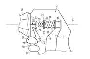
- FIG. 3is a view schematically showing an internal configuration of a housing according to the first embodiment.
- FIG. 4Ais a view schematically showing an internal configuration of the housing in a state in which the treatment target is compressed to some extent between the pair of gripping pieces according to the first embodiment and the closing operation of the pair of gripping pieces is stopped. is there.
- FIG. 4Bis a view schematically showing an internal configuration of the housing when the handle is further squeezed against the grip in the state shown in FIG. 4A.
- FIG. 4Cis a diagram schematically showing an internal configuration of the housing when an operation input is performed on the first operating device in the state shown in FIG. 4B.
- FIG. 5is a view schematically showing an internal configuration of a housing according to a first modified example of the first embodiment.
- FIG. 6is a view schematically showing an internal configuration of a housing according to a second modified example of the first embodiment.
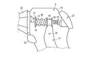
- FIG. 7is a view schematically showing an internal configuration of a housing according to a second embodiment.
- FIG. 8is a view schematically showing an internal configuration of a housing according to a first modified example of the second embodiment.
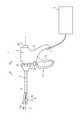
- FIG. 1is a view showing a system in which a treatment instrument 1 which is a surgical instrument of the present embodiment is used.
- the treatment tool 1is an energy treatment tool that uses treatment energy to seal and / or cut a living tissue such as a blood vessel.
- the treatment tool 1includes a holdable housing 2, a shaft (sheath) 5 connected to the distal end side of the housing 2, and an end effector 6 provided at the distal end of the shaft 5.
- One end of a cable 7is connected to the housing 2.
- the other end of the cable 7is detachably connected to the power supply 3.
- the shaft 5is extended around the longitudinal axis C as a central axis.
- the direction along the longitudinal axis Cis taken as the longitudinal direction.
- one side in the longitudinal directionis referred to as a tip side (arrow C1 side), and the other side is referred to as a base end side (arrow C2 side).
- the housing 2is provided with a grip (fixed handle) 16 and a handle (movable handle) 17 is rotatably attached.
- the handle 17is connected to the housing 2 inside the housing 2.
- the protruding portion of the handle 17 from the housing 2is provided with a holding portion 23 held by the operator.
- the handle 17is pivoted relative to the housing 2 so that the handle 17 opens or closes relative to the grip 16.
- the end effector 6includes a first gripping piece 13 and a second gripping piece 14 that can be opened and closed between the first gripping piece 13.
- the second grip piece 14is attached to the tip of the shaft 5 so as to be pivotable about a pivot axis.
- the handle 17 and the second grip piece 14are connected to each other via a drive shaft 15 extending in the longitudinal direction inside the shaft 5.
- the drive shaft 15moves in the longitudinal direction with respect to the shaft 5 and the housing 2 to open or close the pair of gripping pieces 13, 14.
- both of the gripping pieces 13 and 14are rotatably attached to the shaft 5.
- the open / close direction of the end effector 6intersects (is substantially perpendicular to) the longitudinal axis C.
- the side in which the second gripping piece 14 opens with respect to the first gripping piece 13is the opening direction (arrow Y1) of the second gripping piece 14, and the second gripping piece 14 is The side closed with respect to the first gripping piece 13 is taken as the closing direction (arrow Y2) of the second gripping piece 14.
- a direction intersecting (substantially perpendicular) to the longitudinal axis C and intersecting (substantially perpendicular) to the opening / closing direction of the end effector 6is taken as a width direction.
- a rotary operation knob 25is attached to the housing 2.
- the rotary operation knob 25is rotatable relative to the housing 2 about the longitudinal axis C.
- the rotation operation knob 25is connected to the shaft 5.
- the rotation operating knob 25rotates around the longitudinal axis C with respect to the housing 2, whereby the rotation operating knob 25, the shaft 5 and the end effector 6 together rotate with respect to the housing 2.
- the drive shaft 15rotates with respect to the housing 2 around the longitudinal axis C together with the rotary operation knob 25 and the shaft 5.
- Operating buttons 21 and 22are attached to the housing 2.
- the operation buttons 21 and 22are operation input units to which an operation to supply electric energy from the power supply device 3 to the treatment instrument 1 is input.
- FIG. 2is a diagram showing a configuration for supplying electrical energy to the treatment instrument 1.
- the power supply device 3includes a processor 10 and a storage medium 11.
- the processor 10is formed of an integrated circuit or the like including a central processing unit (CPU), an application specific integrated circuit (ASIC) or a field programmable gate array (FPGA). Only one processor 10 may be provided in the power supply device 3, or a plurality of processors 10 may be provided in the power supply device 3. Processing in the processor 10 is performed in accordance with a program stored in the processor 10 or the storage medium 11.
- the storage medium 11also stores a processing program used by the processor 10 and parameters, functions, tables, and the like used in operations by the processor 10.
- the processor 10detects an operation input on the operation buttons 21 and 22.
- the treatment tool 1is provided with at least one electrical element (electrical element).
- the treatment tool 1is provided with a first electrical element 27 and a second electrical element 28.
- the power supply 3is provided with a first output source 8 and a second output source 9.
- the first output source 8includes a conversion circuit and the like, and converts the power from the battery power source or the outlet power source into the electrical energy supplied to the first electrical element 27. Then, the first output source 8 outputs the converted electrical energy to the first electrical element 27.
- the second output source 9includes a conversion circuit and the like, and converts the power from the battery power source or the outlet power source into the electrical energy supplied to the second electrical element 28. Then, the second output source 9 outputs the converted electrical energy to the second electrical element 28.
- Each of the electrical elements 27, 28is operated by being supplied with electrical energy.
- the end effector 6is provided with a bipolar electrode as a first electrical element 27, and the first output source 8 outputs high frequency power as electrical energy to the bipolar electrode.
- the first output source 8outputs high frequency power as electrical energy to the bipolar electrode.
- a heateris provided in the end effector 6 as the second electrical element 28, and DC power or AC power is output as electrical energy from the second output source 9 to the heater.
- Heater heatis generated by supplying DC power or AC power to the heater.
- the heater heatis generated as the treatment energy by the generation of the heater heat in a state where the treatment object is held between the gripping pieces 13 and 14. The treatment subject is sealed or cut by the heater heat.
- an ultrasonic transduceris provided inside the housing 2 as a second electric element 28, and the ultrasonic transducer is a rod member (not shown) that forms one of the gripping pieces 13 and 14.
- AC power of a certain frequency rangeis output as electric energy.
- AC poweris supplied to the ultrasonic transducer, ultrasonic vibration is generated, and ultrasonic vibration generated by the ultrasonic transducer is transmitted to one of the gripping pieces 13 and 14 through the rod member.
- Ultrasonic vibrationis transmitted to one of the holding pieces 13 and 14 in a state where the treatment target is held between the holding pieces 13 and 14, whereby ultrasonic vibration is applied as treatment energy to the treatment target.
- the treatment targetis sealed or dissected by frictional heat resulting from ultrasonic vibration.
- the operation button (first operation device) 21is provided on the proximal end face 19 of the housing 2.
- the operation button 21is disposed in the vicinity of the longitudinal axis C and protrudes to the proximal side with respect to the proximal end face 19 of the housing 2.
- the operation button 21is movable along the longitudinal direction with respect to the housing 2.
- the operation button 21is pushed into the housing 2 and moved to the tip side with respect to the housing 2, whereby an operation input (first operation input) with the operation button 21 is performed.
- Inside the housing 2two electrical contacts (not shown) are provided, each of the electrical contacts being via an electrical path (not shown) extending through the interior of the housing 2 and the interior of the cable 7 It is electrically connected to the processor 10.
- an electrical signal indicating that an operation input on the operation button 21 has been performedis transmitted to the processor 10.
- a pressure equal to or greater than a predetermined valueacts on the operation button 21
- an electrical signal indicating that an operation input on the operation button 21 has been performedis transmitted to the processor 10.
- an electrical signal indicating that an operation input with the operation button 21 is performedis transmitted to the processor 10 Ru.
- the operation button (second operation device) 22is provided on the front end surface 18 of the housing 2.
- the operation button 22is disposed at a position separated from the longitudinal axis C.
- the operation button 22protrudes to the tip side with respect to the tip surface 18 of the housing 2.
- the operation button 22is movable along the longitudinal direction with respect to the housing 2.
- an operation input (second operation input) with the operation button 22is performed.
- two electrical contactsare provided, each of which is connected to the processor 10 via an electrical path (not shown) extending through the interior of the housing 2 and the interior of the cable 7 Electrically connected.
- the processor 10controls the output of the electrical energy from each of the output sources 8 and 9 based on the operation of the operation buttons 21 and 22, and controls the supply of the electrical energy to each of the electrical elements 27 and 28. . Thereby, the application of treatment energy such as high frequency current, ultrasonic vibration and heater heat to the treatment object is controlled. Then, at least one of treatment energy such as high frequency current, ultrasonic vibration and heater heat is applied to the treatment object.
- treatment energysuch as high frequency current, ultrasonic vibration and heater heat
- the processor 10When the operation input is performed by the operation button 21, the processor 10 causes the treatment instrument 1 to be supplied with electrical energy in the first supply state. Then, when the operation input is performed by the operation button 22, the processor 10 causes the treatment instrument 1 to be supplied with electric energy in a second supply state different from the first supply state.
- a bipolar electrodeis provided as the first electrical element 27, and a heater is provided as the second electrical element 28.
- the first supply stateelectrical energy is supplied only to the bipolar electrode.
- the second supply stateelectrical energy is supplied to both the bipolar electrode and the heater.
- the electric energyis supplied to the treatment instrument 1 in the second supply state, so that both the high frequency current and the heater heat are simultaneously treated. Granted to the subject. Thereby, a treatment is performed in which the treatment target is sealed or coagulated at the same time as the treatment.
- the bipolar electrode and the ultrasonic transducerIn the first supply state, the bipolar electrode and the ultrasonic transducer Electrical energy is supplied to both. For this reason, in the state where the treatment object is held between the holding pieces 13 and 14, by supplying electric energy to the treatment instrument 1 in the first supply state, both high frequency current and ultrasonic vibration are simultaneously performed. It is given to the treatment subject. As a result, a treatment is performed in which the treatment subject is incised simultaneously with sealing or coagulation. Also, in this embodiment, in the second supply state, electrical energy is supplied only to the bipolar electrode.
- electrical energyis supplied to the heater in each of the first supply state and the second supply state.
- Electric energyis supplied to the treatment instrument 1 in the first supply state in a state in which the treatment target is held between the holding pieces 13 and 14, whereby heater heat is applied to the treatment target as treatment energy.
- a treatmentis performed in which the treatment subject is incised simultaneously with sealing or coagulation.
- heater heatis given to a treatment object by supplying electrical energy to the treatment tool 1 in a 2nd supply state in the state by which the treatment object was hold
- electric energy smaller than the heater heat applied to the treatment target in the first supply stateis supplied to the heater.
- a treatment for sealing or coagulating the treatment targetis performed.
- the handle 17is connected to the housing 2 via a fulcrum pin 35.
- the handle 17pivots relative to the housing 2 about the fulcrum pin 35.
- the drive shaft 15includes a movable pipe 31 coupled to the handle 17 inside the housing 2, and a movable shaft 32 extending from the movable pipe 31 to the distal end side and connected to the end effector 6.
- the movable pipe 31is formed in a substantially cylindrical shape and extends along the longitudinal axis C.
- the central axis of the movable pipe 31coincides or substantially coincides with the central axis (longitudinal axis C) of the shaft 5. That is, the movable pipe 31 and the shaft 5 are disposed coaxially or substantially coaxially.
- the movable pipe 31is disposed inside the housing 2 so as to be movable in the longitudinal direction with respect to the housing 2 and rotatable around the longitudinal axis C with respect to the housing 2.
- the movable pipe 31includes a projecting portion 33 that protrudes toward the outer peripheral side.
- the movable pipe 31includes a distal end side portion 41 positioned on the distal end side with respect to the projecting portion 33, and a proximal end side portion 51 positioned on the proximal end side with respect to the projecting portion 33.
- the projecting portion 33is located between the distal end side portion 41 and the proximal end portion 51.
- a spring mechanism 40is provided inside the housing 2.
- the spring mechanism 40is disposed in series and concentrically with the spring 45 (first elastic member) connected to or in contact with the movable pipe 31, and the slider 43 connected or in contact with the spring 45.
- a tubular slider (first slider) 43is disposed on the outer periphery of the distal end side portion 41 of the movable pipe 31.
- the slider 43is disposed apart from the protrusion 33 toward the tip end.
- the slider 43is attached to the movable pipe 31 so as to be movable in the longitudinal direction.
- the slider 43is coupled to the handle 17.
- the rotation of the handle 17 relative to the housing 2causes the slider 43 to move in the longitudinal direction relative to the housing 2.
- the slider 43is connected to the handle 17 at a position between the fulcrum pin 35 and the holding portion 23. Therefore, when the holding portion 23 of the handle 17 moves to the proximal side toward the grip 16, the slider 43 moves to the proximal side with respect to the housing 2.
- An elastic spring 45is provided on the outer periphery of the distal end side portion 41 of the movable pipe 31.
- the spring 45is a coil spring.
- the spring 45is disposed between the protrusion 33 and the slider 43.
- the spring 45extends along the longitudinal axis C and is arranged coaxially or substantially coaxially with the movable pipe 31.
- the distal end of the spring 45is connected to or in contact with the slider 43 and the proximal end of the spring 45 is connected to or in contact with the projection 33.
- the spring 45is disposed between the protrusion 33 and the slider 43 in a reference state in which the spring 45 is contracted by a predetermined displacement from a natural state (natural length).
- the elastic coefficient of the spring 45is k1.
- the amount of displacement (amount of contraction) from the natural state (natural length) of the spring 45 in a state where the space between the handle 17 and the grip 16 is closedis x1.
- the elastic force F1k1 ⁇ x1 of the spring 45 acts on the projecting portion 33 on the proximal side.
- a tubular slider (second slider) 53is disposed on the outer periphery of the proximal end portion 51 of the movable pipe 31.
- the slider 53is spaced apart from the protrusion 33 toward the proximal end.
- the slider 53is attached to the movable pipe 31 so as to be movable in the longitudinal direction.
- the slider 53is provided with an electrical contact whose electrical contact state changes in response to the pressing state of the operation button 21.
- An elastic spring 55is provided on the outer periphery of the proximal end portion 51 of the movable pipe 31.
- the spring 55is a coil spring.
- the spring 55is disposed between the protrusion 33 and the slider 53.
- the spring 55is extended along the longitudinal axis C, and is arranged coaxially or substantially coaxially with the movable pipe 31 and the spring 45. Also, the spring 45 and the spring 55 are arranged in series.
- the proximal end of the spring 55is connected to or in contact with the slider 53, and the distal end of the spring 55 is connected to or in contact with the projection 33.
- the spring 55is disposed between the protrusion 33 and the slider 53 in a reference state in which the spring 55 is contracted by a predetermined displacement from a natural state (natural length).
- the elastic coefficient of the spring 55is k2.
- the displacement amount (contraction amount) from the natural state (natural length) of the spring 55is x2.
- the elastic force F2k2 ⁇ x2 of the spring 55 acts on the protrusion 33 toward the tip end.
- the projecting portion 33 of the movable pipe 31is pressed to the base end side by the elastic force F1 of the spring 45, and is pressed to the distal end side by the elastic force F2 of the spring 55. Therefore, the resultant of the elastic force F1 and the elastic force F2 acts on the movable pipe 31.
- the elastic force F2is a force that acts on the opposite side in the longitudinal direction with respect to the elastic force F1.
- the elastic coefficients k1 and k2 and the displacements x1 and x2are set so that the magnitude of the elastic force F2 is smaller than the magnitude of the elastic force F1. For this reason, on the movable pipe 31, a resultant force obtained by subtracting the elastic force F2 from the elastic force F1 acts on the base end side.
- the slider 43moves to the proximal side with respect to the housing 2 together with the movable pipe 31. Therefore, the position of the slider 43 with respect to the movable pipe 31 does not change. Therefore, the spring 45 does not change from the reference state.
- the space between the handle 17 and the grip 16is closed until the handle 17 abuts on a regulating member provided on the grip 16 or the like.
- the protrusion 33is pressed by the spring 45 to the proximal side.
- the elastic force F1 acting on the projecting portion 33is determined by the displacement x1 from the natural length of the spring 45 regardless of the magnitude of the force applied to the handle 17 by the operator.
- the elastic force F2 which acts on the protrusion part 33 from the spring 55becomes large rather than the case where the spring 55 is a reference state. For this reason, when the operation button 21 is pressed, the elastic force F2 acting from the spring 55 to the protrusion 33 toward the tip end is larger than in a state where the operation button 21 is not pressed. Then, as the elastic force F2 increases, the resultant force acting on the protrusion 33 toward the base end decreases. Thus, the amount of contraction x 2 of the spring 55 changes in response to the operation input on the operation button 21.
- the resultant force acting on the movable pipe 31is transmitted to the end effector 6 via the movable shaft 32 and affects the gripping force applied to the treatment object between the gripping pieces 13 and 14.
- the operatorinserts the end effector 6 into a body cavity such as the abdominal cavity and places a living tissue such as a blood vessel as a treatment target between the grasping pieces 13 and 14. Then, the housing 2 and the holding portion 23 of the handle 17 are held, and the handle 17 is pressed toward the grip 16 to close the holding pieces 13 and 14. The grip between the handle 17 and the grip 16 is closed by further squeezing the handle 17 against the grip 16 in a state where the grip pieces 13 and 14 are closed. At this time, the spring 55 is maintained in the reference state, and the spring 45 is further contracted from the reference state. Therefore, a combined force of the elastic force F1 of the spring 45 in a state of being contracted further from the reference state and the elastic force F2 of the spring 55 in the reference state act on the projecting portion 33 of the movable pipe 31.
- the electrical energyis supplied to the treatment device 1 in the first supply state. Then, treatment energy is applied from the end effector 6 to the treatment target, and the treatment target gripped between the gripping pieces 13 and 14 is sealed or solidified.
- the contracted state of the spring 45does not change, but the spring 55 further contracts from the reference state.
- the combined force of the elastic force F1 of the spring 45 in a further contracted state from the reference state and the elastic force F2 of the spring 55 in a state further contracted from the reference stateact on the projecting portion 33 of the movable pipe 31.
- the elastic force F2 acting on the projecting portion 33 from the spring 55is larger than when the spring 55 is in the reference state.
- the elastic force F2 acting on the movable pipe 31 toward the distal end sideis larger than that in the second supply state, and the resultant force acting on the movable pipe 31 toward the proximal end side is smaller. For this reason, in the first supply state, the gripping force applied to the treatment target is smaller than in the second supply state.
- the gripping force applied to the treatment targetchanges. Therefore, the gripping force can be changed while the displacement amount x1 of the spring 45 is maintained constant. That is, it is possible to apply different gripping forces to the treatment target in accordance with the treatment to be performed while keeping the handle 17 in a gripped state.
- the spring 55is disposed substantially concentric with the spring 45 and in series. For this reason, in the movable pipe 31, the virtual action point on which the elastic force F1 of the spring 45 acts and the virtual action point on which the elastic force F2 of the spring 55 acts approximately coincide with each other. Thereby, the stability of the operation of changing the contracted state of the springs 45 and 55 is improved. Moreover, the transferability of the force when the elastic forces F1 and F2 act on the movable pipe 31 is improved.
- the spring 45 and the spring 55are disposed substantially concentrically with the movable pipe 31. Therefore, the transferability of the force when the resultant force of the elastic forces F1 and F2 is transmitted to the end effector 6 through the movable pipe 31 is improved.
- a dome switch 24is attached to the operation button 21.
- the dome switch 24is disposed to face the slider 53. Inside the dome switch 24, a plurality of electrical contacts are provided. Then, when pressure above the predetermined value acts on the dome switch 24, the electrical contacts are in contact with each other, and an electrical signal indicating that the operation input with the operation button 21 is performed as described above is sent to the processor 10. It is transmitted.
- the operation button 21When the operation button 21 is pressed, the operation button 21 moves toward the distal end with respect to the housing 2, and the dome switch 24 abuts the slider 53 from the proximal end. Then, the slider 53 is pressed to the distal end side by the dome switch 24, and the dome switch 24 is pressed to the proximal end side by the spring 55.
- a force equal to or greater than a predetermined valueis applied to the dome switch 24, that is, when the contraction amount x2 of the spring 55 becomes a predetermined contraction amount or more, the power supply device 3 to the treatment instrument 1 Supply of electrical energy.
- the slider 53moves to the tip side with respect to the movable pipe 31, and the spring 55 contracts from the natural state.
- the protrusion 33is pressed by the spring 55 toward the tip end. Therefore, in the state where the operation input with the operation button 21 is performed, the elastic force F2 acting on the tip end side from the spring 55 to the distal end side is larger than the state where the operation input with the operation button 21 is not performed.
- the gripping force suitable for the treatmentcan be given to the treatment subject by changing the gripping force given to the treatment subject corresponding to the treatment.
- the operation button (first operation device) 21is attached to the front end surface 18 of the housing 2.
- the operation button 21includes an operation member 71 and a link member 72.
- the operating member 71is movable along the longitudinal direction with respect to the housing 2. Inside the housing 2 two electrical contacts (not shown) are provided, each of the electrical contacts being electrically connected to the power supply 3 via an electrical circuit extending through the interior of the housing 2 and the cable 7 Connected.
- the processor 10 Be doneWhen the operating member 71 is pressed against the housing 2, electrical conduction is established between the two electrical contacts, and an electrical signal indicating that an operation input with the operating button 21 has been performed is transmitted to the processor 10 Be done. Then, the electrical energy in the first supply state is supplied from the power supply device 3 to the treatment instrument 1.
- the treatment targetis sealed.
- the link member 72is attached to the inside of the housing 2. One end of the link member 72 is connected to the operation member 71. The other end of the link member 72 extends toward the movable pipe 31 and includes an abutting portion 75. When the operation member 71 moves relative to the housing 2, the contact portion 75 moves relative to the housing 2.
- the slider 53 and the spring (second elastic member) 55are attached to the outer periphery of the movable pipe 31 on the tip end side of the slider 43. Also, the proximal end of the spring 55 is connected to or in contact with the slider 43, and the tip of the spring 55 is connected to or in contact with the slider 53.
- the spring 55is disposed between the slider 43 and the slider 53 in a non-biased state (natural state). The spring 55 is arranged in series coaxially or substantially coaxially with the spring 45 and the movable pipe 31.
- the operation member 71 of the operation button 21When the operation member 71 of the operation button 21 is pressed, the operation member 71 moves toward the base end with respect to the housing 2, and the contact portion 75 contacts the slider 53 from the tip end side.
- the slider 53is moved to the base end side with respect to the movable pipe 31 by being pressed to the base end side by the contact portion 75, and the spring 55 contracts from the natural state.
- the projecting portion 33 of the movable pipe 31is pressed toward the proximal end by the elastic force F1 of the spring 45 and the elasticity of the spring 55 It is pressed to the proximal side by force F2. Therefore, the resultant of the elastic force F1 of the spring 45 and the elastic force F2 of the spring 55 acts on the movable pipe 31.
- the elastic force F1 and the elastic force F2are forces directed to the same side. Therefore, on the movable pipe 31, a resultant force obtained by adding the elastic force F2 to the elastic force F1 acts on the base end side.
- the elastic force F1 and the elastic force F2 acting on the projecting portion 33are compared with the state in which the operation input with the operation button 22 is performed.
- the combined strength with Therefore, in the first supply state (first output state), the resultant force acting on the movable pipe 31is larger than that in the second supply state (second output state).
- Second EmbodimentA second embodiment of the present invention will be described with reference to FIG.
- the second embodimentis a modification of the configuration of the first embodiment as follows.
- the same parts as those of the first embodimentare denoted by the same reference numerals, and the description thereof is omitted.
- the operation button 21is provided on the distal end surface 18 of the housing 2 and includes an operation member 71 and a link member 72.
- the slider 43 and the spring (first elastic member) 45are attached to the movable pipe 31 at the base end side of the projecting portion 33, and the slider 53 and the spring (second elastic member) at the tip end side of the projecting portion 33 55 is attached.
- the spring 45is extended along the longitudinal axis C, and is arranged coaxially or substantially coaxially with the movable pipe 31.
- the proximal end of the spring 45is connected or in contact with the slider 43, and the tip of the spring 45 is connected or in contact with the projection 33 of the movable pipe 31.
- the spring 45is disposed between the protrusion 33 and the slider 43 in a reference state in which the spring 45 is contracted by a predetermined displacement from a natural state (natural length).
- the spring 55extends along the longitudinal axis C and is arranged coaxially or substantially coaxially with the movable pipe 31.
- the distal end of the spring 55is connected to or in contact with the slider 53, and the proximal end of the spring 55 is connected to or in contact with the projection 33 of the movable pipe 31.
- the spring 55is attached between the protrusion 33 and the slider 53 in a non-biased state (natural state).
- the slider 43is attached to the handle 17 at a position opposite to the holding portion 23 with respect to the fulcrum pin 35. Therefore, when the holding portion 23 of the handle 17 is closed with respect to the grip 16, the handle 17 is rotated with respect to the housing 2 centering on the fulcrum pin 35, and the slider 43 is moved to the tip side with respect to the housing 2 . In addition, when the slider 43 and the drive shaft 15 move together with the housing 2 to the tip side, the gap between the gripping pieces 13 and 14 is closed.
- the operation member 71 of the operation button 21When the operation member 71 of the operation button 21 is pressed, the operation member 71 moves toward the base end with respect to the housing 2, and the contact portion 75 contacts the slider 53 from the tip end side. Then, the slider 53 moves to the base end side with respect to the movable pipe 31, and the spring 55 contracts from the natural state.
- the projecting portion 33 of the movable pipe 31is pressed to the tip side by the elastic force F1 of the spring 45 and the elastic force of the spring 55 It is pushed proximally by F2.
- the magnitude of the elastic force F1is larger than the magnitude of the elastic force F2.
- the resultant force obtained by subtracting the elastic force F2 from the elastic force F1acts on the tip end side. Therefore, in the first supply state, the resultant force acting on the movable pipe 31 is smaller than in the second supply state.
- a gripping force larger than that in the first supply state in which the treatment target is sealedis applied to the treatment target.
- the gripping force applied to the treatment subjectchanges in accordance with the selected supply state of the electrical energy, whereby the gripping force suitable for the treatment can be applied to the treatment subject.
- the treatment targetis sealed.
- the slider 53 and the spring (second elastic member) 55are attached to the movable pipe 31 at the base end side of the slider 43.
- the distal end of the spring 55is connected to or in contact with the slider 43, and the proximal end of the spring 55 is connected to or in contact with the slider 53.
- the spring 55is disposed between the slider 43 and the slider 53 in a non-biased state (natural state).
- the spring 55is arranged in series coaxially or substantially coaxially with the spring 45 and the movable pipe 31.
- the operation button 21When the operation button 21 is pressed, the operation button 21 contacts the slider 53 from the base end side.
- the slider 53is moved to the tip side with respect to the movable pipe 31 by being pressed to the tip side by the operation button 21, and the spring 55 contracts from the natural state.
- the spring 55is contracted from the natural state by being pressed to the proximal end side by the operation button 21.
- the projecting portion 33 of the movable pipe 31is pressed to the tip side by the elastic force F1 of the spring 45 and the elastic force of the spring 55 The distal end side is pressed by F2. Therefore, on the movable pipe 31, a resultant force obtained by adding the elastic force F2 of the spring 55 to the elastic force F1 of the spring 45 acts on the tip end side. Therefore, in the present modification, in the state in which the operation input with the operation button 21 is performed, the elastic force F1 and the elastic force F2 acting on the projecting portion 33 are compared with the state in which the operation input with the operation button 22 is performed. The combined strength with Therefore, in the first supply state, the resultant force acting on the movable pipe 31 is larger than in the second supply state.
- the incision of the treatment targetis performed in the state where the operation input with the operation button 21 is performed (first supply state).
- second supply statein which the operation input with the operation button 22 is performed (the second supply state)
- sealing of the treatment targetis performed.
- a gripping force larger than the first supply state in which the incision of the treatment target is performedcan be applied to the treatment target.
- the treatment targetis dissected.
- first supply stateIn the case where the treatment target is sealed and the operation input with the operation button 22 is performed
- second supply statethe treatment target is dissected.
- a gripping force larger than the second supply state in which the incision of the treatment target is performedcan be applied to the treatment target.
- a gripping force suitable for the selected treatment modecan be applied to the treatment object.
- the surgical instrument (1)is provided at a distal end portion of the sheath (5) extending along the longitudinal axis from the proximal end toward the distal end, and a pair of grips capable of gripping the treatment target
- the pair of gripsare connected to at least one of the piece (13, 14) and the pair of grip pieces (13, 14), and moved along the longitudinal axis (C) with respect to the sheath (5)
- a drive shaft (15)which opens or closes between the pieces (13, 14), an electric element (27, 28) capable of applying treatment energy to the treatment object by supplying electric energy, and an operation input
- the first operating device (21) and the drive shaft (15)to cause the electric element (27, 28) to supply the electric energy in the first supply state.
- First elastic membercapable of giving 45) and movable relative to the drive shaft (15), and changing the amount of contraction (x1) of the first elastic member (45) by moving relative to the drive shaft (15)
- An elastic force (F2)can be applied to the slider (43) and the drive shaft (15), and the first operating device (21) is disposed concentrically and in series with the first elastic member (45).
- a second elastic member (55)whose contraction amount (x2) changes in response to the operation input at step b).
- the present inventionis not limited to the above embodiment, and can be variously modified in the implementation stage without departing from the scope of the invention.
- the embodimentsmay be implemented in combination as appropriate as possible, in which case the combined effect is obtained.
- the above embodimentsinclude inventions of various stages, and various inventions can be extracted by an appropriate combination of a plurality of disclosed configuration requirements.
Landscapes
- Health & Medical Sciences (AREA)
- Surgery (AREA)
- Engineering & Computer Science (AREA)
- Life Sciences & Earth Sciences (AREA)
- Biomedical Technology (AREA)
- Public Health (AREA)
- Nuclear Medicine, Radiotherapy & Molecular Imaging (AREA)
- Veterinary Medicine (AREA)
- General Health & Medical Sciences (AREA)
- Heart & Thoracic Surgery (AREA)
- Medical Informatics (AREA)
- Molecular Biology (AREA)
- Animal Behavior & Ethology (AREA)
- Physics & Mathematics (AREA)
- Otolaryngology (AREA)
- Plasma & Fusion (AREA)
- Dentistry (AREA)
- Mechanical Engineering (AREA)
- Surgical Instruments (AREA)
Abstract
Description
Translated fromJapanese本発明は、一対の把持片の間で生体組織等の処置対象を把持する手術器具に関する。The present invention relates to a surgical instrument for gripping a treatment target such as a living tissue between a pair of gripping pieces.
US2015/0335347A1には、一対の把持片の間で血管等の処置対象を把持し、把持される処置対象に処置エネルギーを付与することで、処置を行う手術器具が開示されている。この手術器具では、把持される処置対象を封止する処置と、把持される処置対象を切開する処置とで、処置対象への処置エネルギーの付与状態が異なる。処置対象への処置エネルギーの付与状態は、操作装置での操作入力に応じて、切替えられる。US2015 / 0335347A1 discloses a surgical instrument for performing treatment by holding a treatment target such as a blood vessel between a pair of holding pieces and applying treatment energy to the treatment target to be held. In this surgical instrument, the application state of the treatment energy to the treatment object differs between the treatment for sealing the treatment object to be grasped and the treatment for cutting the treatment object to be grasped. The application state of the treatment energy to the treatment target is switched according to the operation input on the operation device.
US2015/0335347A1の手術器具等で処置を行う場合、封止処置と切開処置とでは、処置エネルギーの付与状態が異なるため、処置対象に付与される把持力の適切な大きさが異なる。このため、行われる処置に応じて、処置対象に付与される把持力が切替えられることが好ましい。When the treatment is performed using a surgical instrument or the like of US2015 / 0335347A1, since the application state of treatment energy is different between the sealing treatment and the incision treatment, the appropriate magnitude of the gripping force applied to the treatment object is different. For this reason, it is preferable that the gripping force applied to the treatment target be switched depending on the treatment to be performed.
本発明の目的は、行われる処置に応じて処置対象を把持する把持力が切替えられる手術器具を提供することにある。An object of the present invention is to provide a surgical instrument in which the gripping force for gripping an object to be treated is switched according to the treatment to be performed.
前記目的を達成するため、本発明のある態様の手術器具は、基端から先端に向かって長手軸に沿って延設されるシースと、前記シースの先端部に設けられ、処置対象を把持可能な一対の把持片と、前記一対の把持片の少なくとも一方に連結され、前記シースに対して前記長手軸に沿って移動することにより前記一対の把持片の間が開く又は閉じる駆動シャフトと、電気エネルギーが供給されることにより前記処置対象に処置エネルギーを付与可能な電気的要素と、操作が入力されることにより、前記電気的要素に第1の供給状態で前記電気エネルギーを供給させる、第1の操作装置と、前記駆動シャフトに弾性力を付与可能な第1の弾性部材と、前記駆動シャフトに対して移動可能に配置され、前記駆動シャフトに対して移動することにより前記第1の弾性部材の収縮量を変化させるスライダと、前記駆動シャフトに弾性力を付与可能で、前記第1の弾性部材に対して同心かつ直列に配置され、前記第1の操作装置での操作入力に対応して収縮量が変化する第2の弾性部材と、を備える。In order to achieve the above object, a surgical instrument according to an aspect of the present invention includes a sheath extending along a longitudinal axis from a proximal end toward a distal end, and provided at a distal end of the sheath and capable of gripping an object to be treated A pair of gripping pieces, a drive shaft connected to at least one of the pair of gripping pieces, and a drive shaft that opens or closes between the pair of gripping pieces by moving along the longitudinal axis with respect to the sheath; An electrical element capable of applying treatment energy to the treatment target by being supplied with energy, and an operation being inputted, thereby supplying the electric energy in the first supply state to the electrical element, first And a first elastic member capable of applying an elastic force to the drive shaft, and movably disposed with respect to the drive shaft by moving relative to the drive shaft. A slider for changing the amount of contraction of the first elastic member, and elastic force can be applied to the drive shaft, and arranged concentrically and in series with the first elastic member, in the first operating device And a second elastic member whose contraction amount changes in response to the operation input.
(第1の実施形態)
本発明の第1の実施形態について、図1乃至図4Cを参照して説明する。図1は、本実施形態の手術器具である処置具1が用いられるシステムを示す図である。処置具1は、処置エネルギーを用いて、血管等の生体組織を封止及び/又は切開するエネルギー処置具である。図1に示すように、処置具1は、保持可能なハウジング2と、ハウジング2の先端側に連結されるシャフト(シース)5と、シャフト5の先端部に設けられるエンドエフェクタ6と、を備える。ハウジング2には、ケーブル7の一端が接続される。ケーブル7の他端は、電源装置3に分離可能に接続される。シャフト5は、長手軸Cを中心軸として、延設される。ここで、長手軸Cに沿う方向を長手方向とする。また、長手方向の一方側を先端側(矢印C1側)とし、他方側を基端側(矢印C2側)とする。First Embodiment
A first embodiment of the present invention will be described with reference to FIGS. 1 to 4C. FIG. 1 is a view showing a system in which a
ハウジング2には、グリップ(固定ハンドル)16が設けられるとともに、ハンドル(可動ハンドル)17が回動可能に取付けられる。ハンドル17は、ハウジング2の内部においてハウジング2に対して連結される。ハンドル17におけるハウジング2からの突出部分には、術者によって保持される保持部23が設けられる。ハンドル17がハウジング2に対して回動することにより、ハンドル17はグリップ16に対して開く又は閉じる。The
エンドエフェクタ6は、第1の把持片13と、第1の把持片13との間が開閉可能な第2の把持片14と、を備える。第2の把持片14は、シャフト5の先端部に回動軸を中心として回動可能に取付けられている。また、ハンドル17と第2の把持片14との間は、シャフト5の内部に長手方向に沿って延設される駆動シャフト15を介して、連結される。ハンドル17をグリップ16に対して開く又は閉じることにより、駆動シャフト15がシャフト5及びハウジング2に対して長手方向に沿って移動し、一対の把持片13,14の間が開く又は閉じる。また、別のある実施例では、把持片13,14の両方が、シャフト5に対して回動可能に取付けられる。The
エンドエフェクタ6の開閉方向は、長手軸Cに対して交差する(略垂直となる)。エンドエフェクタ6の開閉方向のうち、第2の把持片14が第1の把持片13に対して開く側を第2の把持片14の開方向(矢印Y1)とし、第2の把持片14が第1の把持片13に対して閉じる側を第2の把持片14の閉方向(矢印Y2)とする。また、長手軸Cに対して交差し(略垂直で)、かつ、エンドエフェクタ6の開閉方向に対して交差する(略垂直な)方向を幅方向とする。The open / close direction of the
ハウジング2には、回転操作ノブ25が取付けられている。回転操作ノブ25は、長手軸Cを中心としてハウジング2に対して回転可能である。回転操作ノブ25は、シャフト5に連結されている。回転操作ノブ25がハウジング2に対して長手軸Cの軸回りに回転することにより、回転操作ノブ25、シャフト5及びエンドエフェクタ6が一緒に、ハウジング2に対して回転する。また、駆動シャフト15は、回転操作ノブ25及びシャフト5と一緒に、長手軸Cの軸回りについてハウジング2に対して回転する。A
ハウジング2には、操作ボタン21,22が取付けられている。操作ボタン21,22は、電源装置3から処置具1に電気エネルギーを供給させる操作が入力される操作入力部である。
図2は、処置具1に電気エネルギーを供給する構成を示す図である。図2に示すように、電源装置3は、プロセッサ10及び記憶媒体11を備える。プロセッサ10は、CPU(Central Processing Unit)、ASIC(Application Specific Integrated Circuit)又はFPGA(Field Programmable Gate Array)等を含む集積回路等から形成される。プロセッサ10は、電源装置3において1つのみ設けられてもよく、電源装置3において複数設けられてもよい。プロセッサ10での処理は、プロセッサ10又は記憶媒体11に記憶されたプログラムに従って行われる。また、記憶媒体11には、プロセッサ10で用いられる処理プログラム、及び、プロセッサ10での演算で用いられるパラメータ、関数及びテーブル等が記憶される。プロセッサ10は、操作ボタン21,22での操作入力を検出する。FIG. 2 is a diagram showing a configuration for supplying electrical energy to the
処置具1には、少なくとも1つの電気的要素(電気的素子)が設けられる。本実施形態では、処置具1には、第1の電気的要素27及び第2の電気的要素28が、設けられる。また、電源装置3には、第1の出力源8及び第2の出力源9が、設けられている。第1の出力源8は、変換回路等を備え、バッテリー電源又はコンセント電源等からの電力を第1の電気的要素27に供給される電気エネルギーに変換する。そして、第1の出力源8は、変換した電気エネルギーを第1の電気的要素27に出力する。また、第2の出力源9は、変換回路等を備え、バッテリー電源又はコンセント電源等からの電力を第2の電気的要素28に供給される電気エネルギーに変換する。そして、第2の出力源9は、変換した電気エネルギーを第2の電気的要素28に出力する。電気的要素27,28のそれぞれは、電気エネルギーが供給されることにより、作動される。The
本実施形態では、エンドエフェクタ6に第1の電気的要素27としてバイポーラ電極が設けられ、第1の出力源8からバイポーラ電極に電気エネルギーとして高周波電力が出力される。把持片13,14の間で処置対象が把持される状態でバイポーラ電極に高周波電力が供給されることにより、バイポーラ電極の間で処置対象を通して高周波電流が流れ、処置対象に処置エネルギーとして高周波電流が付与される。高周波電流に起因する熱によって、処置対象は、変性され、封止又は切開される。In the present embodiment, the
また、本実施形態では、第2の電気的要素28として、ヒータが、エンドエフェクタ6に設けられ、第2の出力源9からヒータに、電気エネルギーとして直流電力又は交流電力が、出力される。ヒータに直流電力又は交流電力が供給されることにより、ヒータ熱が発生する。把持片13,14の間で処置対象が把持された状態でヒータ熱が発生することにより、処置対象にヒータ熱が処置エネルギーとして付与される。ヒータ熱によって、処置対象は、封止又は切開される。Further, in the present embodiment, a heater is provided in the
また、別のある実施例では、ハウジング2の内部に第2の電気的要素28として超音波トランスデューサが設けられ、超音波トランスデューサは、把持片13,14の一方を形成するロッド部材(図示しない)に接続される。そして、第2の出力源9から超音波トランスデューサに、電気エネルギーとして所定の周波数範囲のある周波数の交流電力が、出力される。超音波トランスデューサに交流電力が供給されることにより、超音波振動が発生し、超音波トランスデューサで発生した超音波振動は、ロッド部材を通して、把持片13,14の一方に伝達される。把持片13,14の間で処置対象が把持された状態で超音波振動が把持片13,14の一方に伝達されることにより、処置対象に超音波振動が処置エネルギーとして付与される。処置対象は、超音波振動に起因する摩擦熱によって、封止又は切開される。Also, in another embodiment, an ultrasonic transducer is provided inside the
操作ボタン(第1の操作装置)21は、ハウジング2の基端面19に設けられている。操作ボタン21は、長手軸Cの近傍に配置され、ハウジング2の基端面19に対して基端側へ突出している。操作ボタン21は、ハウジング2に対して長手方向に沿って移動可能である。操作ボタン21がハウジング2に対して押し込まれ、ハウジング2に対して先端側へ移動することにより、操作ボタン21での操作入力(第1の操作入力)が行われる。ハウジング2の内部には2つの電気接点(図示しない)が設けられ、電気接点のそれぞれは、ハウジング2の内部及びケーブル7の内部を通って延設される電気経路(図示しない)を介して、プロセッサ10に電気的に接続される。操作ボタン21が押圧されると、2つの電気接点の間において電気的な導通が確立され、操作ボタン21での操作入力が行われたことを示す電気信号が、プロセッサ10に伝達される。ある実施例では、操作ボタン21に所定の値以上の圧力が作用した場合に、操作ボタン21での操作入力が行われたことを示す電気信号がプロセッサ10に伝達される。また、別のある実施例では、操作ボタン21がハウジング2に対して一定以上の距離を移動した場合に、操作ボタン21での操作入力が行われたことを示す電気信号がプロセッサ10に伝達される。The operation button (first operation device) 21 is provided on the
操作ボタン(第2の操作装置)22は、ハウジング2の先端面18に設けられている。操作ボタン22は、長手軸Cに対して離間した位置に配置されている。操作ボタン22は、ハウジング2の先端面18に対して先端側へ突出している。また、操作ボタン22は、ハウジング2に対して長手方向に沿って移動可能である。操作ボタン22がハウジング2に対して押し込まれ、操作ボタン22がハウジング2に対して基端側へ移動することにより、操作ボタン22での操作入力(第2の操作入力)が行われる。ハウジング2の内部には、2つの電気接点が設けられ、電気接点のそれぞれは、ハウジング2の内部及びケーブル7の内部を通って延設される電気経路(図示しない)を介して、プロセッサ10に電気的に接続される。操作ボタン22が押圧されると、2つの電気接点の間において電気的な導通が確立され、操作ボタン22での操作入力が行われたことを示す電気信号が、プロセッサ10に伝達される。The operation button (second operation device) 22 is provided on the
プロセッサ10は、操作ボタン21,22での操作に基づいて、出力源8,9のそれぞれからの電気エネルギーの出力を制御し、電気的要素27,28のそれぞれへの電気エネルギーの供給を制御する。これにより、高周波電流、超音波振動及びヒータ熱等の処置エネルギーの、処置対象への付与が制御される。そして、高周波電流、超音波振動及びヒータ熱等の処置エネルギーのうち少なくとも1つが、処置対象へ付与される。The
操作ボタン21で操作入力が行われた場合は、プロセッサ10は、第1の供給状態で処置具1に電気エネルギーを供給させる。そして、操作ボタン22で操作入力が行われた場合は、プロセッサ10は、第1の供給状態とは異なる第2の供給状態で処置具1に電気エネルギーを供給させる。When the operation input is performed by the
本実施形態では、第1の電気的要素27としてバイポーラ電極が設けられ、かつ、第2の電気的要素28としてヒータが設けられる。第1の供給状態では、バイポーラ電極にのみ、電気エネルギーが供給される。このため、把持片13,14の間で処置対象が把持された状態では、第1の供給状態で処置具1に電気エネルギーが供給されることにより、高周波電流のみが、処置対象に付与される。これにより、処置対象を封止又は凝固する処置が行われる。また、第2の供給状態では、バイポーラ電極及びヒータの両方に、電気エネルギーが供給される。このため、把持片13,14の間で処置対象が把持された状態では、第2の供給状態で処置具1に電気エネルギーが供給されることにより、高周波電流及びヒータ熱の両方が同時に、処置対象に付与される。これにより、処置対象を封止又は凝固と同時に切開する処置が行わる。In the present embodiment, a bipolar electrode is provided as the first
例えば、第1の電気的要素27としてバイポーラ電極が設けられ、かつ、第2の電気的要素28として超音波トランスデューサが設けられる実施例では、第1の供給状態において、バイポーラ電極及び超音波トランスデューサの両方に、電気エネルギーが供給される。このため、把持片13,14の間で処置対象が把持された状態では、第1の供給状態で処置具1に電気エネルギーが供給されることにより、高周波電流及び超音波振動の両方が同時に、処置対象に付与される。これにより、処置対象を封止又は凝固と同時に切開する処置が行われる。また、この実施例では、第2の供給状態において、バイポーラ電極にのみ、電気エネルギーが供給される。このため、把持片13,14の間で処置対象が把持された状態では、第2の供給状態で処置具1に電気エネルギーが供給されることにより、高周波電流のみが、処置対象に付与される。これにより、処置対象を封止又は凝固する処置が行われる。For example, in the embodiment where a bipolar electrode is provided as the first
また、例えば、電気的要素27,28としてヒータのみが設けられる実施例では、第1の供給状態及び第2の供給状態のそれぞれにおいて、ヒータに、電気エネルギーが供給される。把持片13,14の間で処置対象が把持された状態で第1の供給状態で処置具1に電気エネルギーが供給されることにより、処置エネルギーとしてヒータ熱が処置対象に付与される。そして、処置対象を封止又は凝固と同時に切開する処置が行われる。また、把持片13,14の間で処置対象が把持された状態で第2の供給状態で処置具1に電気エネルギーが供給されることにより、ヒータ熱が処置対象に付与される。この際、第1の供給状態で処置対象に付与されるヒータ熱よりも小さい電気エネルギーがヒータに供給される。そして、処置対象を封止又は凝固する処置が行われる。Also, for example, in an embodiment in which only the heater is provided as the
図3に示すように、ハンドル17は、支点ピン35を介してハウジング2に連結されている。ハンドル17は、支点ピン35を中心として、ハウジング2に対して回動する。As shown in FIG. 3, the
駆動シャフト15は、ハウジング2の内部においてハンドル17と連結される可動パイプ31と、可動パイプ31から先端側へ延設され、エンドエフェクタ6に接続される可動シャフト32と、を備える。可動パイプ31は、略筒状に形成され、長手軸Cに沿って延設されている。可動パイプ31の中心軸は、シャフト5の中心軸(長手軸C)と、一致又は略一致する。すなわち、可動パイプ31とシャフト5は、同軸又は略同軸に配置されている。可動パイプ31は、ハウジング2に対して長手方向に沿って移動可能で、かつ、ハウジング2に対して長手軸Cを中心として回転可能な状態で、ハウジング2の内部に配置されている。The
可動パイプ31は、外周側に向かって突出する突出部33を備える。可動パイプ31は、突出部33に対して先端側に位置する先端側部分41と、突出部33に対して基端側に位置する基端側部分51とを備える。突出部33は、先端側部分41と基端側部分51との間に位置する。The
ハウジング2の内部には、バネ機構40が設けられている。バネ機構40は、可動パイプ31に接続される又は接触するバネ(第1の弾性部材)45と、バネ45に接続される又は接触するスライダ43と、バネ45に対して直列かつ同心に配置されるバネ(第2の弾性部材)55と、バネ55に接続される又は接触するスライダ53と、を備える。A
可動パイプ31の先端側部分41の外周には、筒形状のスライダ(第1のスライダ)43が配設されている。スライダ43は、突出部33に対して先端側へ離間して配置されている。スライダ43は、可動パイプ31に対して長手方向に沿って移動可能に取付けられている。スライダ43は、ハンドル17に連結されている。ハンドル17がハウジング2に対して回動することにより、スライダ43がハウジング2に対して長手方向に沿って移動する。スライダ43は、支点ピン35と保持部23との間の位置において、ハンドル17に連結されている。このため、ハンドル17の保持部23がグリップ16に向かって基端側へ移動すると、スライダ43はハウジング2に対して基端側へ移動する。A tubular slider (first slider) 43 is disposed on the outer periphery of the distal
可動パイプ31の先端側部分41の外周には、弾性を有するバネ45が設けられている。バネ45は、コイルバネである。バネ45は、突出部33とスライダ43との間に配置されている。バネ45は、長手軸Cに沿って延設され、可動パイプ31と同軸又は略同軸に配置されている。バネ45の先端は、スライダ43に接続されるか又は接触し、バネ45の基端は、突出部33に接続されるか又は接触する。バネ45は、自然状態(自然長)から所定の変位だけ収縮した基準状態で、突出部33とスライダ43との間に配置される。ここで、バネ45の弾性係数をk1とする。また、ハンドル17とグリップ16の間が閉じた状態におけるバネ45の自然状態(自然長)からの変位量(収縮量)をx1とする。突出部33には、バネ45の弾性力F1=k1・x1が、基端側へ作用する。An
可動パイプ31の基端側部分51の外周には、筒形状のスライダ(第2のスライダ)53が配設されている。スライダ53は、突出部33に対して基端側へ離間して配置されている。スライダ53は、可動パイプ31に対して長手方向に沿って移動可能に取付けられている。スライダ53には、操作ボタン21の押圧状態に対応して電気的な接触状態が変化する電気接点が設けられている。A tubular slider (second slider) 53 is disposed on the outer periphery of the
可動パイプ31の基端側部分51の外周には、弾性を有するバネ55が設けられている。バネ55は、コイルバネである。バネ55は、突出部33とスライダ53との間に配置されている。バネ55は、長手軸Cに沿って延設され、可動パイプ31及びバネ45に対して同軸又は略同軸に配置されている。また、バネ45及びバネ55は、直列に配置されている。バネ55の基端は、スライダ53に接続されるか又は接触し、バネ55の先端は、突出部33に接続されるか又は接触している。操作ボタン21が押圧されていない状態では、スライダ53の基端面は、操作ボタン21に対して離間している。バネ55は、自然状態(自然長)から所定の変位だけ収縮した基準状態で、突出部33とスライダ53との間に配置されている。ここで、バネ55の弾性係数をk2とする。また、バネ55の自然状態(自然長)からの変位量(収縮量)をx2とする。突出部33には、バネ55の弾性力F2=k2・x2が、先端側へ作用する。An
可動パイプ31の突出部33は、バネ45の弾性力F1によって基端側へ押圧されるとともに、バネ55の弾性力F2によって先端側へ押圧されている。このため、可動パイプ31には、弾性力F1と弾性力F2の合力が作用する。ここで、弾性力F2は、弾性力F1に対して、長手方向について反対側に作用する力である。また、弾性力F2の大きさが弾性力F1の大きさよりも小さくなるように、弾性係数k1,k2、変位量x1,x2等が設定される。このため、可動パイプ31には、弾性力F1から弾性力F2を減算した合力が、基端側へ作用する。The projecting
ハンドル17の保持部23がグリップ16に向かって押圧されると、ハンドル17が支点ピン35を中心としてハウジング2に対して回動するとともに、ハンドル17の保持部23がハウジング2に対して基端側へ移動する。このとき、ハンドル17からスライダ43、バネ45及び突出部33を介して駆動シャフト15に駆動力が伝達され、スライダ43、バネ45、及び駆動シャフト15が一緒に、ハウジング2に対して基端側へ移動する。駆動シャフト15がハウジング2(シャフト5)に対して基端側へ移動することにより、エンドエフェクタ6が閉動作し、把持片13,14の間が閉じる。このとき、スライダ43は、可動パイプ31と一緒に、ハウジング2に対して基端側へ移動する。このため、可動パイプ31に対するスライダ43の位置は、変化しない。したがって、バネ45は、基準状態から変化しない。When the holding
把持片13,14の間が閉じ、処置対象がある程度圧縮されると、エンドエフェクタ6の閉動作が停止し、駆動シャフト15のハウジング2に対する基端側への移動が停止する(図4A参照)。この状態で、ハンドル17をグリップ16に対してさらに握り込むと、可動パイプ31のハウジング2に対する基端側への移動が停止しているため、図4Bに示すように、スライダ43が可動パイプ31に対して基端側へ移動する。このとき、スライダ43が可動パイプ31に対して基端側へ移動することにより、バネ45は、基準状態からさらに収縮する。このため、バネ45が基準状態である場合よりも、バネ45から突出部33に作用する弾性力F1が大きくなる。そして、ハンドル17がグリップ16等に設けられる規制部材に当接するまで、ハンドル17とグリップ16との間が閉じる。突出部33は、バネ45によって基端側へ押圧される。突出部33に作用する弾性力F1は、術者がハンドル17に加える力の大きさに関わらず、バネ45の自然長からの変位量x1によって決定される。When the object to be treated is compressed to a certain extent, the closing operation of the
また、操作ボタン21が押圧されていない状態では、スライダ53の基端面は、操作ボタン21に対して離間している。このため、突出部33には、基準状態でのバネ55の弾性力F2が作用する。Further, in a state where the
ハンドル17とグリップ16の間が閉じた状態で操作ボタン21での操作入力が行われると、操作ボタン21がハウジング2の内部に向かって押し込まれ、操作ボタン21がハウジング2に対して先端側へ移動する。このとき、図4Cに示すように、ハウジング2の内部において操作ボタン21がスライダ53に基端側から当接することにより、スライダ53は、操作ボタン21によって先端側へ押圧される。ハンドル17がグリップ16に対して握り込まれた状態では、可動パイプ31のハウジング2に対する移動は停止している。このため、スライダ53は、可動パイプ31に対して先端側へ移動する。スライダ53が可動パイプ31に対して先端側へ移動することにより、バネ55は、基準状態からさらに収縮する。このため、バネ55が基準状態である場合よりも、バネ55から突出部33に作用する弾性力F2が大きくなる。このため、操作ボタン21が押圧された場合、操作ボタン21が押圧されない状態に比べて、バネ55から突出部33に先端側へ作用する弾性力F2が大きくなる。そして、弾性力F2が大きくなることにより、突出部33に基端側へ作用する合力が、小さくなる。このように、バネ55は、操作ボタン21での操作入力に対応して、収縮量x2が変化する。When an operation input with the
可動パイプ31に作用する合力は、可動シャフト32を介してエンドエフェクタ6に伝達され、把持片13,14の間で処置対象に付与される把持力に影響を及ぼす。例えば、可動パイプ31に基端側へ作用する合力が大きいほど、把持片13,14の間で処置対象に付与される把持力が大きくなる。The resultant force acting on the
次に、本実施形態の処置具1の作用及び効果について説明する。処置具1を用いて処置を行う際には、術者は、腹腔等の体腔内にエンドエフェクタ6を挿入し、血管等の生体組織を把持片13,14の間に処置対象として配置する。そして、ハウジング2及びハンドル17の保持部23を保持し、ハンドル17をグリップ16に向かって押圧することにより、把持片13,14の間を閉じる。把持片13,14の間が閉じた状態でハンドル17をグリップ16に対してさらに握り込むことにより、ハンドル17とグリップ16の間が閉じる。このとき、バネ55は、基準状態で維持され、バネ45は、基準状態からさらに収縮した状態となる。このため、可動パイプ31の突出部33には、基準状態からさらに収縮した状態におけるバネ45の弾性力F1と基準状態でのバネ55の弾性力F2との合力が作用する。Next, the operation and effects of the
この状態で、操作ボタン22で操作入力が行われると、第2の供給状態で電気エネルギーが処置具1に供給される。そして、エンドエフェクタ6から処置対象に処置エネルギーが付与され、把持片13,14の間で把持される処置対象が封止又は凝固と同時に切開される。このとき、バネ45の収縮状態(収縮量)及びバネ55の収縮状態(収縮量)は、変化しない。したがって、バネ45から突出部33に作用する弾性力F1とバネ55から突出部33に作用する弾性力F2の合力は、変化しない。このため、第2の供給状態では、駆動シャフト15には、基準状態からさらに収縮した状態でのバネ45の弾性力F1と、基準状態でのバネ55の弾性力F2との合力が作用する。In this state, when the operation input is performed by the
操作ボタン21での操作入力が行われると、第1の供給状態で電気エネルギーが処置具1に供給される。そして、エンドエフェクタ6から処置対象に処置エネルギー付与され、把持片13,14の間で把持される処置対象が封止又は凝固される。このとき、バネ45の収縮状態は変化しないが、バネ55は、基準状態からさらに収縮する。このため、可動パイプ31の突出部33には、基準状態からさらに収縮した状態でのバネ45の弾性力F1と基準状態からさらに収縮した状態でのバネ55の弾性力F2の合力が作用する。ここで、バネ55から突出部33に作用する弾性力F2は、バネ55が基準状態である場合に比べて、大きい。したがって、第1の供給状態では、第2の供給状態に比べて、可動パイプ31に先端側へ作用する弾性力F2が大きくなり、可動パイプ31に基端側へ作用する合力が小さくなる。このため、第1の供給状態では、第2の供給状態に比べて、処置対象に付与される把持力が小さくなる。When the operation input with the
ここで、発熱体で発生する熱を処置エネルギーとして用いる場合、処置対象を切開する処置では、処置対象に大きい把持力が付与されることが好ましい。一方、処置対象を封止する処置では、処置対象の切断防止のため、大きい把持力を処置対象に付与できない。本実施形態では、処置対象の切開を行う第2の供給状態において、処置対象の封止を行う第1の供給状態での把持力よりも大きい把持力が処置対象に付与される。このため、切開処置において、封止処置よりも大きい把持力を処置対象に付与することができる。これにより、処置具1を用いた処置における処置性能が向上する。このように、処置に応じて処置対象に付与される把持力が変化することにより、処置に応じた適切な把持力を処置対象に付与することができる。Here, when using the heat which generate | occur | produces with a heat generating body as a treatment energy, it is preferable that big grasping power is provided to a treatment object by the treatment which incises a treatment object. On the other hand, in the treatment for sealing the treatment object, a large gripping force can not be applied to the treatment object to prevent cutting of the treatment object. In the present embodiment, in the second supply state in which the treatment target is incised, a gripping force larger than the gripping force in the first supply state in which the treatment target is sealed is applied to the treatment target. For this reason, in the incision treatment, a larger gripping force than the sealing treatment can be applied to the treatment target. Thereby, the treatment performance in the treatment using the
また、本実施形態では、操作ボタン21に連結されるバネ55の変位量x2が変化することにより、処置対象に付与される把持力が変化する。したがって、バネ45の変位量x1が一定に維持されたままで、把持力を変化させることができる。すなわち、ハンドル17を握り込んだ状態のままで、行う処置に応じて異なる把持力を処置対象に付与することができる。Further, in the present embodiment, when the displacement amount x2 of the
また、バネ55は、バネ45に対して略同心で、かつ、直列に配置されている。このため、可動パイプ31において、バネ45の弾性力F1が作用する仮想的な作用点と、バネ55の弾性力F2が作用する仮想的な作用点が、略一致する。これにより、バネ45,55の収縮状態を変化させる操作の安定性が向上する。また、弾性力F1,F2が可動パイプ31に作用する際の力の伝達性が向上する。In addition, the
また、バネ45及びバネ55は、可動パイプ31と略同心に配置されている。このため、弾性力F1,F2の合力が可動パイプ31を介してエンドエフェクタ6まで伝達される際の力の伝達性が向上する。Further, the
(第1の実施形態の第1の変形例)
本実施形態の第1の変形例について、図5を用いて説明する。本変形例では、バネ55は、自然状態(自然長)で、可動パイプ31に取付けられている。グリップ16とハンドル17との間が閉じ、かつ、操作ボタン21が押圧されない状態では、操作ボタン21とスライダ53との間は、離間している。First Modification of First Embodiment
A first modified example of the present embodiment will be described with reference to FIG. In the present modification, the
操作ボタン21には、ドームスイッチ24が取付けられている。ドームスイッチ24は、スライダ53に対向して配置される。ドームスイッチ24の内部には、複数の電気接点が設けられる。そして、ドームスイッチ24に所定の値以上の圧力が作用することにより、電気接点同士が接触し、前述のように操作ボタン21での操作入力が行われたことを示す電気信号が、プロセッサ10に伝達される。A
グリップ16とハンドル17との間が閉じ、かつ、操作ボタン21が押圧されない状態では、ドームスイッチ24とスライダ53との間は、離間している。このため、バネ55は自然状態で維持され、バネ55の弾性力F2は0になる。したがって、可動パイプ31の突出部33には、基準状態からさらに収縮した状態でのバネ45の弾性力F1のみが作用する。このため、突出部33に作用する弾性力F1と弾性力F2との合力は、弾性力F1と略同一となる。また、操作ボタン22での操作入力が行われた状態では、突出部33に作用する合力は、変化しない。When the
操作ボタン21が押圧されると、操作ボタン21がハウジング2に対して先端側へ移動し、ドームスイッチ24が、スライダ53に基端側から当接する。そして、スライダ53がドームスイッチ24によって先端側へ押圧されるとともに、ドームスイッチ24がバネ55によって基端側へ押圧される。ドームスイッチ24に所定の値以上の力が加えられることにより、すなわち、バネ55の収縮量x2が所定の収縮量が所定の値以上となることにより、電源装置3から処置具1に、第1の供給状態での電気エネルギーが供給される。When the
操作ボタン21での操作入力が行われた状態では、スライダ53が可動パイプ31に対して先端側へ移動し、バネ55が自然状態から収縮する。突出部33には、バネ55の弾性力F2(=k2・x2)が、先端側へ作用する。突出部33は、バネ55によって先端側へ押圧される。このため、操作ボタン21での操作入力が行われた状態では、操作ボタン21での操作入力が行われない状態に比べて、バネ55から突出部33に先端側へ作用する弾性力F2が大きくなり、突出部33に基端側へ作用する合力が小さくなる。このため、本変形例においても、処置に対応して処置対象に付与される把持力が変化することにより、処置に適した把持力を処置対象に付与することができる。In the state where the operation input with the
また、本変形例では、バネ55の収縮量x2が所定の値以上となることにより、操作ボタン21での操作入力が行われたことを示す電気信号が電源装置3に伝達され、第1の供給状態で電気エネルギーが出力される。このため、処置対象に付与される把持力が処置に適した大きさに変化した後に、処置エネルギーを用いた処置を行うことができる。Further, in the present modification, when the contraction amount x2 of the
(第1の実施形態の第2の変形例)
本実施形態の第2の変形例について、図6を用いて説明する。本変形例では、操作ボタン(第1の操作装置)21は、ハウジング2の先端面18に取付けられている。操作ボタン21は、操作部材71と、リンク部材72とを備える。操作部材71は、ハウジング2に対して、長手方向に沿って移動可能である。ハウジング2の内部には、2つの電気接点(図示しない)が設けられ、電気接点のそれぞれは、ハウジング2及びケーブル7の内部を通って延設される電気回路を介して、電源装置3と電気的に接続されている。操作部材71がハウジング2に対して押圧されると、2つの電気接点の間において電気的な導通が確立され、操作ボタン21での操作入力が行われたことを示す電気信号がプロセッサ10に伝達される。そして、第1の供給状態での電気エネルギーが、電源装置3から処置具1に供給される。Second Modification of First Embodiment
A second modified example of the present embodiment will be described using FIG. In the present modification, the operation button (first operation device) 21 is attached to the
また、本変形例では、操作ボタン21での操作入力が行われた状態(第1の供給状態)では、処置対象の切開が行われ、操作ボタン22での操作入力が行われた状態(第2の供給状態)では、処置対象の封止が行われる。Further, in the present modification, in the state (first supply state) in which the operation input with the
リンク部材72は、ハウジング2の内部に取付けられている。リンク部材72の一端は、操作部材71に連結されている。リンク部材72の他端は、可動パイプ31に向かって延伸し、当接部75を備える。操作部材71がハウジング2に対して移動することにより、当接部75がハウジング2に対して移動する。The
また、本変形例では、スライダ53及びバネ(第2の弾性部材)55は、スライダ43の先端側において、可動パイプ31の外周に取付けられている。また、バネ55の基端は、スライダ43に接続されるか又は接触し、バネ55の先端は、スライダ53に接続されるか又は接触している。バネ55は、付勢されない状態(自然状態)で、スライダ43とスライダ53との間に配置される。バネ55は、バネ45及び可動パイプ31に対して直列かつ同軸又は略同軸に配置されている。Further, in the present modification, the
ハンドル17とグリップ16との間が閉じ、かつ、操作部材71が押圧されない状態では、リンク部材72の当接部75とスライダ53とは離間している。このため、バネ55は自然状態で維持され、バネ55の弾性力F2は0になる。したがって、可動パイプ31の突出部33には、基準状態からさらに収縮した状態でのバネ45の弾性力F1のみが作用する。このため、突出部33に作用する弾性力F1と弾性力F2との合力は、弾性力F1と略同一となる。また、操作ボタン22での操作入力が行われた状態(第2の供給状態)では、突出部33に作用する合力は、変化しない。When the space between the
操作ボタン21の操作部材71が押圧されると、操作部材71がハウジング2に対して基端側へ移動するとともに、当接部75がスライダ53に先端側から当接する。当接部75によって基端側へ押圧されることによりスライダ53が可動パイプ31に対して基端側へ移動し、バネ55が自然状態から収縮する。スライダ43には、バネ55の弾性力F2(=k2・x2)が、基端側へ作用する。このため、突出部33は、スライダ43及びバネ45を介して、バネ55によって基端側へ押圧される。When the
操作ボタン21での操作入力が行われた状態(第1の供給状態)では、可動パイプ31の突出部33は、バネ45の弾性力F1によって基端側へ押圧されるとともに、バネ55の弾性力F2によって基端側へ押圧される。このため、可動パイプ31には、バネ45の弾性力F1とバネ55の弾性力F2との合力が作用する。ここで、弾性力F1及び弾性力F2は、同じ側を向く力である。このため、可動パイプ31には、弾性力F1に弾性力F2を加算した合力が、基端側へ作用する。したがって、本変形例では、操作ボタン21での操作入力が行われた状態では、操作ボタン22での操作入力が行われた状態に比べて、突出部33に作用する弾性力F1と弾性力F2との合力が大きくなる。したがって、第1の供給状態(第1の出力状態)では、第2の供給状態(第2の出力状態)に比べて、可動パイプ31に作用する合力が大きくなる。In the state (first supply state) in which the operation input with the
このため、本変形例においても、処置対象の切開を行う第1の供給状態において、封止を行う第2の供給状態よりも大きい把持力が処置対象に付与される。これにより、処置に対応して処置対象に付与される把持力が変化することにより、処置に適した把持力を処置対象に付与することができる。For this reason, also in this modification, in the first supply state in which the incision of the treatment target is performed, a gripping force larger than that in the second supply state in which sealing is performed is applied to the treatment target. Thus, by changing the gripping force applied to the treatment target corresponding to the treatment, the gripping force suitable for the treatment can be applied to the treatment target.
(第2の実施形態)
本発明の第2の実施形態について、図7を参照して説明する。第2の実施形態は、第1の実施形態の構成を次の通り変形したものである。なお、第1の実施形態と同一の部分については同一の符号を付して、その説明は省略する。Second Embodiment
A second embodiment of the present invention will be described with reference to FIG. The second embodiment is a modification of the configuration of the first embodiment as follows. The same parts as those of the first embodiment are denoted by the same reference numerals, and the description thereof is omitted.
本実施形態では、第1の実施形態の第2の変形例と同様に、操作ボタン21は、ハウジング2の先端面18に設けられ、操作部材71とリンク部材72とを備える。In the present embodiment, as in the second modified example of the first embodiment, the
可動パイプ31には、突出部33よりも基端側にスライダ43及びバネ(第1の弾性部材)45が取付けられ、突出部33よりも先端側にスライダ53及びバネ(第2の弾性部材)55が取付けられている。バネ45は、長手軸Cに沿って延設され、可動パイプ31と同軸又は略同軸に配置される。バネ45の基端はスライダ43に接続されるか又は接触し、バネ45の先端は可動パイプ31の突出部33に接続されるか又は接触する。バネ45は、自然状態(自然長)から所定の変位だけ収縮した基準状態で、突出部33とスライダ43との間に配置される。The
バネ55は、長手軸Cに沿って延設され、可動パイプ31と同軸又は略同軸に配置される。バネ55の先端はスライダ53に接続されるか又は接触し、バネ55の基端は可動パイプ31の突出部33に接続されるか又は接触する。バネ55は、付勢されない状態(自然状態)で、突出部33とスライダ53との間に取付けられている。The
スライダ43は、支点ピン35に対して保持部23とは反対側の位置において、ハンドル17に取付けられている。このため、ハンドル17の保持部23がグリップ16に対して閉じることにより、ハンドル17が支点ピン35を中心としてハウジング2に対して回動し、スライダ43がハウジング2に対して先端側へ移動する。また、スライダ43及び駆動シャフト15がハウジング2に対して一緒に先端側へ移動することにより、把持片13,14の間が閉じる。The
把持片13,14の間が閉じると、エンドエフェクタ6の閉動作が停止し、駆動シャフト15のハウジング2に対する先端側への移動が停止する。この状態でハンドル17をグリップ16に対してさらに握り込むと、スライダ43が可動パイプ31に対して先端側へ移動する。このとき、スライダ43が可動パイプ31に対して先端側へ移動することにより、バネ45が基準状態からさらに収縮する。そして、ハンドル17とグリップ16との間が閉じる。突出部33には、バネ45の弾性力F1=k1・x1が、先端側へ作用する。When the gap between the
グリップ16とハンドル17との間が閉じ、かつ、操作部材71が押圧されない状態では、リンク部材72の当接部75とスライダ53とは、離間している。このため、バネ55は自然状態で維持され、バネ55の弾性力F2は0になる。したがって、可動パイプ31の突出部33には、基準状態からさらに収縮した状態でのバネ45の弾性力F1のみが作用する。このため、突出部33に作用する弾性力F1と弾性力F2との合力は、弾性力F1と略同一となる。また、操作ボタン22での操作入力が行われた状態(第2の出力状態)では、突出部33に作用する合力は、変化しない。When the gap between the
操作ボタン21の操作部材71が押圧されると、操作部材71がハウジング2に対して基端側へ移動するとともに、当接部75がスライダ53に先端側から当接する。そして、スライダ53が可動パイプ31に対して基端側へ移動するとともに、バネ55が自然状態から収縮する。突出部33には、バネ55の弾性力F2(=k2・x2)が、基端側へ作用する。このため、突出部33は、バネ55によって基端側へ押圧される。When the
操作ボタン21での操作入力が行われた状態(第1の供給状態)では、可動パイプ31の突出部33は、バネ45の弾性力F1によって先端側へ押圧されるとともに、バネ55の弾性力F2によって基端側へ押圧される。ここで、弾性力F1の大きさは、弾性力F2の大きさよりも大きい。このため、可動パイプ31には、弾性力F1から弾性力F2を減算した合力が、先端側へ作用する。したがって、第1の供給状態では、第2の供給状態に比べて、可動パイプ31に作用する合力が小さくなる。In the state (first supply state) in which the operation input with the
本実施形態においても、処置対象の切開を行う第2の供給状態において、処置対象の封止を行う第1の供給状態よりも大きい把持力が処置対象に付与される。これにより、選択された電気エネルギーの供給状態に対応して処置対象に付与される把持力が変化することにより、処置に適した把持力を処置対象に付与することができる。Also in the present embodiment, in the second supply state in which the treatment target is incised, a gripping force larger than that in the first supply state in which the treatment target is sealed is applied to the treatment target. As a result, the gripping force applied to the treatment subject changes in accordance with the selected supply state of the electrical energy, whereby the gripping force suitable for the treatment can be applied to the treatment subject.
(第2の実施形態の第1の変形例)
本実施形態の第1の変形例について、図8を用いて説明する。本変形例では、操作ボタン21は、ハウジング2の基端面19に設けられている。(First Modified Example of Second Embodiment)
A first modified example of the present embodiment will be described with reference to FIG. In the present modification, the
また、操作ボタン21での操作入力が行われた状態(第1の供給状態)では、処置対象の切開が行われ、操作ボタン22での操作入力が行われた状態(第2の供給状態)では、処置対象の封止が行われる。In the state where the operation input with the
また、スライダ53及びバネ(第2の弾性部材)55は、スライダ43の基端側において、可動パイプ31に取付けられている。バネ55の先端は、スライダ43に接続されるか又は接触し、バネ55の基端は、スライダ53に接続されるか又は接触している。バネ55は、付勢されない状態(自然状態)で、スライダ43とスライダ53との間に配置される。バネ55は、バネ45及び可動パイプ31に対して直列かつ同軸又は略同軸に配置されている。The
ハンドル17とグリップ16との間が閉じ、かつ、操作ボタン21が押圧されない状態では、スライダ53と操作ボタン21とは、離間している。このため、バネ55は自然状態で維持され、バネ55の弾性力F2は0になる。したがって、可動パイプ31の突出部33には、基準状態からさらに収縮した状態でのバネ45の弾性力F1のみが作用する。このため、突出部33に作用する弾性力F1と弾性力F2との合力は、弾性力F1と略同一となる。また、操作ボタン22での操作入力が行われた状態(第2の供給状態)では、突出部33に作用する合力は、変化しない。When the space between the
操作ボタン21が押圧されると、操作ボタン21がスライダ53に基端側から当接する。操作ボタン21によって先端側へ押圧されることにより、スライダ53が可動パイプ31に対して先端側へ移動し、バネ55が自然状態から収縮する。バネ55は、操作ボタン21によって基端側へ押圧されることにより、自然状態から収縮する。スライダ43には、バネ55の弾性力F2(=k2・x2)が、先端側へ作用する。このため、突出部33は、スライダ43及びバネ45を介して、バネ55によって先端側へ押圧される。When the
操作ボタン21での操作入力が行われた状態(第1の供給状態)では、可動パイプ31の突出部33は、バネ45の弾性力F1によって先端側へ押圧されるとともに、バネ55の弾性力F2によって先端側へ押圧される。このため、可動パイプ31には、バネ45の弾性力F1にバネ55の弾性力F2を加算した合力が、先端側へ作用する。したがって、本変形例では、操作ボタン21での操作入力が行われた状態では、操作ボタン22での操作入力が行われた状態に比べて、突出部33に作用する弾性力F1と弾性力F2との合力が大きくなる。したがって、第1の供給状態では、第2の供給状態に比べて、可動パイプ31に作用する合力が大きくなる。In the state (first supply state) in which the operation input with the
このため、本変形例においても、処置対象の切開を行う第1の供給状態において、処置対象の封止を行う第2の供給状態よりも大きい把持力が処置対象に付与される。これにより、これにより、処置に対応して処置対象に付与される把持力が変化することにより、処置に適した把持力を処置対象に付与することができる。For this reason, also in this modification, in the first supply state in which the treatment target is incised, a gripping force larger than that in the second supply state in which the treatment target is sealed is applied to the treatment target. Thus, the gripping force suitable for the treatment can be given to the treatment subject by changing the gripping force given to the treatment subject corresponding to the treatment.
(その他の実施例)
なお、第1の電気的要素27としてバイポーラ電極が設けられ、かつ、第2の電気的要素28として超音波トランスデューサが設けられる実施例にも、前述の実施形態等の構成を適用可能である。この場合、高周波電流のみが処置対象に付与される封止処置では、処置対象に大きい把持力が付与されることが好ましい。一方、高周波電流及び超音波振動の両方が処置対象に付与される切開処置では、超音波振動の伝達性向上のため、大きい把持力を付与できない。(Other embodiments)
The configurations of the above-described embodiments and the like can be applied to an embodiment in which a bipolar electrode is provided as the first
例えば、第1の実施形態の構成において、バイポーラ電極及び超音波トランスデューサが設けられる場合には、操作ボタン21での操作入力が行われた状態(第1の供給状態)では、処置対象の切開が行われ、操作ボタン22での操作入力が行われた状態(第2の供給状態)では、処置対象の封止が行われる。この場合、処置対象の封止処置を行う第2の供給状態において、処置対象の切開を行う第1の供給状態よりも大きい把持力を処置対象に付与することができる。For example, in the configuration of the first embodiment, when the bipolar electrode and the ultrasonic transducer are provided, the incision of the treatment target is performed in the state where the operation input with the
また、例えば、第1の実施形態の第2の変形例の構成において、バイポーラ電極及び超音波トランスデューサが設けられる場合には、操作ボタン21での操作入力が行われた状態(第1の供給状態)では、処置対象の封止が行われ、操作ボタン22での操作入力が行われた状態(第2の供給状態)では、処置対象の切開が行われる。この場合、処置対象の封止処置を行う第1の供給状態において、処置対象の切開を行う第2の供給状態よりも大きい把持力を処置対象に付与することができる。このように、高周波電流と超音波振動が処置エネルギーとして用いられる実施例においても、選択された処置モードに適した把持力を処置対象に付与することができる。Further, for example, in the configuration of the second modified example of the first embodiment, when the bipolar electrode and the ultrasonic transducer are provided, the state where the operation input with the
(実施形態等での共通構成)
手術器具(1)は、基端から先端に向かって長手軸に沿って延設されるシース(5)と、前記シース(5)の先端部に設けられ、処置対象を把持可能な一対の把持片(13,14)と、前記一対の把持片(13,14)の少なくとも一方に連結され、前記シース(5)に対して前記長手軸(C)に沿って移動することにより前記一対の把持片(13,14)の間が開く又は閉じる駆動シャフト(15)と、電気エネルギーが供給されることにより前記処置対象に処置エネルギーを付与可能な電気的要素(27,28)と、操作が入力されることにより、前記電気的要素(27,28)に第1の供給状態で前記電気エネルギーを供給させる、第1の操作装置(21)と、前記駆動シャフト(15)に弾性力(F1)を付与可能な第1の弾性部材(45)と、前記駆動シャフト(15)に対して移動可能に配置され、前記駆動シャフト(15)に対して移動することにより前記第1の弾性部材(45)の収縮量(x1)を変化させるスライダ(43)と、前記駆動シャフト(15)に弾性力(F2)を付与可能で、前記第1の弾性部材(45)に対して同心かつ直列に配置され、前記第1の操作装置(21)での前記操作入力に対応して収縮量(x2)が変化する第2の弾性部材(55)と、を備える。(Common configuration in the embodiment etc.)
The surgical instrument (1) is provided at a distal end portion of the sheath (5) extending along the longitudinal axis from the proximal end toward the distal end, and a pair of grips capable of gripping the treatment target The pair of grips are connected to at least one of the piece (13, 14) and the pair of grip pieces (13, 14), and moved along the longitudinal axis (C) with respect to the sheath (5) A drive shaft (15) which opens or closes between the pieces (13, 14), an electric element (27, 28) capable of applying treatment energy to the treatment object by supplying electric energy, and an operation input The first operating device (21) and the drive shaft (15) to cause the electric element (27, 28) to supply the electric energy in the first supply state. First elastic member capable of giving 45) and movable relative to the drive shaft (15), and changing the amount of contraction (x1) of the first elastic member (45) by moving relative to the drive shaft (15) An elastic force (F2) can be applied to the slider (43) and the drive shaft (15), and the first operating device (21) is disposed concentrically and in series with the first elastic member (45). And a second elastic member (55) whose contraction amount (x2) changes in response to the operation input at step b).
なお、本願発明は、上記実施形態に限定されるものではなく、実施段階ではその要旨を逸脱しない範囲で種々に変形することが可能である。また、各実施形態は可能な限り適宜組み合わせて実施してもよく、その場合組み合わせた効果が得られる。更に、上記実施形態には種々の段階の発明が含まれており、開示される複数の構成要件における適当な組み合わせにより種々の発明が抽出され得る。The present invention is not limited to the above embodiment, and can be variously modified in the implementation stage without departing from the scope of the invention. In addition, the embodiments may be implemented in combination as appropriate as possible, in which case the combined effect is obtained. Furthermore, the above embodiments include inventions of various stages, and various inventions can be extracted by an appropriate combination of a plurality of disclosed configuration requirements.
Claims (13)
Translated fromJapanese前記シースの先端部に設けられ、処置対象を把持可能な一対の把持片と、
前記一対の把持片の少なくとも一方に連結され、前記シースに対して前記長手軸に沿って移動することにより前記一対の把持片の間が開く又は閉じる駆動シャフトと、
電気エネルギーが供給されることにより前記処置対象に処置エネルギーを付与可能な電気的要素と、
操作が入力されることにより、前記電気的要素に第1の供給状態で前記電気エネルギーを供給させる、第1の操作装置と、
前記駆動シャフトに弾性力を付与可能な第1の弾性部材と、
前記駆動シャフトに対して移動可能に配置され、前記駆動シャフトに対して移動することにより前記第1の弾性部材の収縮量を変化させるスライダと、
前記駆動シャフトに弾性力を付与可能で、前記第1の弾性部材に対して同心かつ直列に配置され、前記第1の操作装置での操作入力に対応して収縮量が変化する第2の弾性部材と、
を備える手術器具。A sheath extending along the longitudinal axis from the proximal end to the distal end;
A pair of gripping pieces provided at the distal end of the sheath and capable of gripping the treatment target;
A drive shaft connected to at least one of the pair of gripping pieces and opening or closing between the pair of gripping pieces by moving along the longitudinal axis with respect to the sheath;
An electrical element capable of providing treatment energy to the treatment subject by supplying electric energy;
A first operation device that causes the electric element to be supplied with the electric energy in a first supply state by inputting an operation;
A first elastic member capable of applying an elastic force to the drive shaft;
A slider disposed movably with respect to the drive shaft and changing a contraction amount of the first elastic member by moving with respect to the drive shaft;
A second elasticity that can apply an elastic force to the drive shaft, and is disposed concentrically and in series with the first elastic member, and the amount of contraction changes in response to an operation input on the first operation device. Members,
A surgical instrument comprising:
請求項1の手術器具。And a second operation device for supplying the electrical energy to the electrical element in a second supply state different from the first supply state by inputting an operation.
The surgical instrument of claim 1.
請求項2の手術器具。The combined force of the elastic force acting on the drive shaft from the first elastic member in the first supply state and the elastic force acting on the drive shaft from the second elastic member in the second supply state Different from the resultant force acting on the drive shaft,
The surgical instrument of claim 2.
請求項3の手術器具。The resultant force acting on the drive shaft in the first supply state is smaller than the resultant force acting on the drive shaft when the operation input on the second operating device is input.
The surgical instrument of claim 3.
前記第1の供給状態では、前記電極にのみ前記電気エネルギーが供給され、
前記第2の供給状態では、前記電極及び前記ヒータのそれぞれに前記電気エネルギーが供給される、
請求項4の手術器具。The electrical element includes a heater that generates heat when supplied with the electrical energy, and an electrode provided on each of the pair of gripping pieces,
In the first supply state, the electrical energy is supplied only to the electrode;
In the second supply state, the electrical energy is supplied to each of the electrode and the heater.
The surgical instrument of claim 4.
前記第1の供給状態では、前記電極及び前記超音波トランスデューサのそれぞれに前記電気エネルギーが供給され、
前記第2の供給状態では、前記電極にのみ前記電気エネルギーが供給される、
請求項4の手術器具。The electrical element includes an ultrasonic transducer that generates ultrasonic vibration by being supplied with the electric energy, and an electrode provided on each of the pair of gripping pieces,
In the first supply state, the electrical energy is supplied to each of the electrode and the ultrasonic transducer;
In the second supply state, the electrical energy is supplied only to the electrode.
The surgical instrument of claim 4.
請求項3の手術器具。The resultant force acting on the drive shaft in the first supply state is greater than the resultant force acting on the drive shaft in the second supply state.
The surgical instrument of claim 3.
前記第1の供給状態では、前記電極及び前記ヒータのそれぞれに前記電気エネルギーが供給され、
前記第2の供給状態では、前記電極にのみ前記電気エネルギーが供給される、
請求項7の手術器具。The electrical element includes a heater that generates heat when supplied with the electrical energy, and an electrode provided on each of the pair of gripping pieces,
In the first supply state, the electrical energy is supplied to each of the electrode and the heater;
In the second supply state, the electrical energy is supplied only to the electrode.
The surgical instrument of claim 7.
前記第1の供給状態では、前記電極にのみ前記電気エネルギーが供給され、
前記第2の供給状態では、前記電極及び前記超音波トランスデューサのそれぞれに前記電気エネルギーが供給される、
請求項7の手術器具。The electrical element includes an ultrasonic transducer that generates ultrasonic vibration by being supplied with the electric energy, and an electrode provided on each of the pair of gripping pieces,
In the first supply state, the electrical energy is supplied only to the electrode;
In the second supply state, the electrical energy is supplied to each of the electrode and the ultrasonic transducer.
The surgical instrument of claim 7.
請求項1の手術器具。The elastic force acting on the drive shaft from the second elastic member is opposite to the elastic force acting on the drive shaft from the first elastic member.
The surgical instrument of claim 1.
請求項1の手術器具。The elastic force acting on the drive shaft from the second elastic member faces the same side as the elastic force acting on the drive shaft from the first elastic member.
The surgical instrument of claim 1.
請求項1の手術器具。Each of the first elastic member and the second elastic member is disposed coaxially with the drive shaft.
The surgical instrument of claim 1.
請求項1の手術器具。In the first operation device, the operation is input when the contraction amount of the second elastic member becomes equal to or more than a predetermined value.
The surgical instrument of claim 1.
Priority Applications (2)
| Application Number | Priority Date | Filing Date | Title |
|---|---|---|---|
| PCT/JP2017/023595WO2019003307A1 (en) | 2017-06-27 | 2017-06-27 | Surgical tool |
| US16/717,412US11737809B2 (en) | 2017-06-27 | 2019-12-17 | Surgical instrument |
Applications Claiming Priority (1)
| Application Number | Priority Date | Filing Date | Title |
|---|---|---|---|
| PCT/JP2017/023595WO2019003307A1 (en) | 2017-06-27 | 2017-06-27 | Surgical tool |
Related Child Applications (1)
| Application Number | Title | Priority Date | Filing Date |
|---|---|---|---|
| US16/717,412ContinuationUS11737809B2 (en) | 2017-06-27 | 2019-12-17 | Surgical instrument |
Publications (1)
| Publication Number | Publication Date |
|---|---|
| WO2019003307A1true WO2019003307A1 (en) | 2019-01-03 |
Family
ID=64740444
Family Applications (1)
| Application Number | Title | Priority Date | Filing Date |
|---|---|---|---|
| PCT/JP2017/023595CeasedWO2019003307A1 (en) | 2017-06-27 | 2017-06-27 | Surgical tool |
Country Status (2)
| Country | Link |
|---|---|
| US (1) | US11737809B2 (en) |
| WO (1) | WO2019003307A1 (en) |
Families Citing this family (12)
| Publication number | Priority date | Publication date | Assignee | Title |
|---|---|---|---|---|
| US9072535B2 (en) | 2011-05-27 | 2015-07-07 | Ethicon Endo-Surgery, Inc. | Surgical stapling instruments with rotatable staple deployment arrangements |
| US20120292367A1 (en) | 2006-01-31 | 2012-11-22 | Ethicon Endo-Surgery, Inc. | Robotically-controlled end effector |
| US11980366B2 (en) | 2006-10-03 | 2024-05-14 | Cilag Gmbh International | Surgical instrument |
| US8632535B2 (en) | 2007-01-10 | 2014-01-21 | Ethicon Endo-Surgery, Inc. | Interlock and surgical instrument including same |
| US8573465B2 (en) | 2008-02-14 | 2013-11-05 | Ethicon Endo-Surgery, Inc. | Robotically-controlled surgical end effector system with rotary actuated closure systems |
| US8636736B2 (en) | 2008-02-14 | 2014-01-28 | Ethicon Endo-Surgery, Inc. | Motorized surgical cutting and fastening instrument |
| US9585657B2 (en) | 2008-02-15 | 2017-03-07 | Ethicon Endo-Surgery, Llc | Actuator for releasing a layer of material from a surgical end effector |
| US10945731B2 (en) | 2010-09-30 | 2021-03-16 | Ethicon Llc | Tissue thickness compensator comprising controlled release and expansion |
| US12213666B2 (en) | 2010-09-30 | 2025-02-04 | Cilag Gmbh International | Tissue thickness compensator comprising layers |
| US20140001231A1 (en) | 2012-06-28 | 2014-01-02 | Ethicon Endo-Surgery, Inc. | Firing system lockout arrangements for surgical instruments |
| US9775609B2 (en) | 2013-08-23 | 2017-10-03 | Ethicon Llc | Tamper proof circuit for surgical instrument battery pack |
| US20200054321A1 (en)* | 2018-08-20 | 2020-02-20 | Ethicon Llc | Surgical instruments with progressive jaw closure arrangements |
Citations (5)
| Publication number | Priority date | Publication date | Assignee | Title |
|---|---|---|---|---|
| JP2004129871A (en)* | 2002-10-10 | 2004-04-30 | Olympus Corp | Ultrasonic operating device |
| WO2005122918A1 (en)* | 2004-06-15 | 2005-12-29 | Olympus Corporation | Energy treatment tool |
| US20120022526A1 (en)* | 2010-07-23 | 2012-01-26 | Ethicon Endo-Surgery, Inc. | Electrosurgical cutting and sealing instrument |
| WO2013136587A1 (en)* | 2012-03-13 | 2013-09-19 | オリンパスメディカルシステムズ株式会社 | Treatment tool for endoscope |
| WO2013141217A1 (en)* | 2012-03-19 | 2013-09-26 | オリンパスメディカルシステムズ株式会社 | Surgical gripping device |
Family Cites Families (6)
| Publication number | Priority date | Publication date | Assignee | Title |
|---|---|---|---|---|
| JP5726441B2 (en) | 2010-05-18 | 2015-06-03 | オリンパス株式会社 | manipulator |
| US8480703B2 (en) | 2010-11-19 | 2013-07-09 | Covidien Lp | Surgical device |
| JP5936914B2 (en) | 2011-08-04 | 2016-06-22 | オリンパス株式会社 | Operation input device and manipulator system including the same |
| JP2013042921A (en) | 2011-08-24 | 2013-03-04 | Olympus Corp | Cardiac stimulator system |
| EP3005964A4 (en) | 2013-06-06 | 2017-03-01 | Olympus Corporation | Handle unit and surgical device |
| US10376305B2 (en)* | 2016-08-05 | 2019-08-13 | Ethicon Llc | Methods and systems for advanced harmonic energy |
- 2017
- 2017-06-27WOPCT/JP2017/023595patent/WO2019003307A1/ennot_activeCeased
- 2019
- 2019-12-17USUS16/717,412patent/US11737809B2/enactiveActive
Patent Citations (5)
| Publication number | Priority date | Publication date | Assignee | Title |
|---|---|---|---|---|
| JP2004129871A (en)* | 2002-10-10 | 2004-04-30 | Olympus Corp | Ultrasonic operating device |
| WO2005122918A1 (en)* | 2004-06-15 | 2005-12-29 | Olympus Corporation | Energy treatment tool |
| US20120022526A1 (en)* | 2010-07-23 | 2012-01-26 | Ethicon Endo-Surgery, Inc. | Electrosurgical cutting and sealing instrument |
| WO2013136587A1 (en)* | 2012-03-13 | 2013-09-19 | オリンパスメディカルシステムズ株式会社 | Treatment tool for endoscope |
| WO2013141217A1 (en)* | 2012-03-19 | 2013-09-26 | オリンパスメディカルシステムズ株式会社 | Surgical gripping device |
Also Published As
| Publication number | Publication date |
|---|---|
| US20200121377A1 (en) | 2020-04-23 |
| US11737809B2 (en) | 2023-08-29 |
Similar Documents
| Publication | Publication Date | Title |
|---|---|---|
| WO2019003307A1 (en) | Surgical tool | |
| US20180161062A1 (en) | Treatment tool | |
| US20210128257A1 (en) | Robotic surgical assemblies and electromechanical instruments thereof | |
| JP6467463B2 (en) | Surgical device with jaw force limiter | |
| US20190142506A1 (en) | Energy treatment instrument, control device, and treatment system | |
| EP2446848A1 (en) | Surgery instrument | |
| JP6726786B2 (en) | Hemostatic forceps ultrasonic surgical instrument with clamping force limiting mechanism | |
| US20050149017A1 (en) | Movable handle for vessel sealer | |
| JP2017225882A (en) | Treatment tool and treatment system | |
| JP2015521899A (en) | Surgical instrument with articulated shaft | |
| US12127782B2 (en) | Energy-activation mechanisms for surgical instruments | |
| JP6574069B2 (en) | Disengagement mechanism for electrosurgical forceps | |
| CN107427312A (en) | Combined Medical Devices | |
| US20220022944A1 (en) | Surgical instrument with increased lever stroke | |
| US10463422B2 (en) | Surgical instrument with stopper assembly | |
| US20180271587A1 (en) | Energy treatment instrument | |
| CN115317137A (en) | Controllers and Surgical Systems | |
| US20220409232A1 (en) | Energy based surgical instruments and systems | |
| US20230129956A1 (en) | Surgical instruments and methods incorporating ultrasonic and electrosurgical functionality | |
| US20210369328A1 (en) | System and user interface for displaying actual operating parameters and ideal operating parameters | |
| WO2019008631A1 (en) | Medical device and surgical system | |
| CN111182843B (en) | Gap-controlled vessel sealing and dissection | |
| WO2018225258A1 (en) | Treatment instrument and treatment system | |
| US20230225782A1 (en) | Control device, electrosurgical instrument and method for controlling an electrosurgical instrument | |
| WO2020026453A1 (en) | Treatment tool and airtight member for treatment tool |
Legal Events
| Date | Code | Title | Description |
|---|---|---|---|
| 121 | Ep: the epo has been informed by wipo that ep was designated in this application | Ref document number:17915303 Country of ref document:EP Kind code of ref document:A1 | |
| NENP | Non-entry into the national phase | Ref country code:DE | |
| 122 | Ep: pct application non-entry in european phase | Ref document number:17915303 Country of ref document:EP Kind code of ref document:A1 | |
| NENP | Non-entry into the national phase | Ref country code:JP |