WO2019001585A1 - Electric heater - Google Patents
Electric heaterDownload PDFInfo
- Publication number
- WO2019001585A1 WO2019001585A1PCT/CN2018/093958CN2018093958WWO2019001585A1WO 2019001585 A1WO2019001585 A1WO 2019001585A1CN 2018093958 WCN2018093958 WCN 2018093958WWO 2019001585 A1WO2019001585 A1WO 2019001585A1
- Authority
- WO
- WIPO (PCT)
- Prior art keywords
- wall
- electric heater
- heating
- heat transfer
- fluid chamber
- Prior art date
- Legal status (The legal status is an assumption and is not a legal conclusion. Google has not performed a legal analysis and makes no representation as to the accuracy of the status listed.)
- Ceased
Links
Images


Classifications
- B—PERFORMING OPERATIONS; TRANSPORTING
- B60—VEHICLES IN GENERAL
- B60H—ARRANGEMENTS OF HEATING, COOLING, VENTILATING OR OTHER AIR-TREATING DEVICES SPECIALLY ADAPTED FOR PASSENGER OR GOODS SPACES OF VEHICLES
- B60H1/00—Heating, cooling or ventilating [HVAC] devices
- B60H1/22—Heating, cooling or ventilating [HVAC] devices the heat being derived otherwise than from the propulsion plant
- B60H1/2215—Heating, cooling or ventilating [HVAC] devices the heat being derived otherwise than from the propulsion plant the heat being derived from electric heaters
- B60H1/2218—Heating, cooling or ventilating [HVAC] devices the heat being derived otherwise than from the propulsion plant the heat being derived from electric heaters controlling the operation of electric heaters
- B—PERFORMING OPERATIONS; TRANSPORTING
- B60—VEHICLES IN GENERAL
- B60H—ARRANGEMENTS OF HEATING, COOLING, VENTILATING OR OTHER AIR-TREATING DEVICES SPECIALLY ADAPTED FOR PASSENGER OR GOODS SPACES OF VEHICLES
- B60H1/00—Heating, cooling or ventilating [HVAC] devices
- B60H1/22—Heating, cooling or ventilating [HVAC] devices the heat being derived otherwise than from the propulsion plant
- B60H1/2215—Heating, cooling or ventilating [HVAC] devices the heat being derived otherwise than from the propulsion plant the heat being derived from electric heaters
- B60H1/2221—Heating, cooling or ventilating [HVAC] devices the heat being derived otherwise than from the propulsion plant the heat being derived from electric heaters arrangements of electric heaters for heating an intermediate liquid
- F—MECHANICAL ENGINEERING; LIGHTING; HEATING; WEAPONS; BLASTING
- F24—HEATING; RANGES; VENTILATING
- F24H—FLUID HEATERS, e.g. WATER OR AIR HEATERS, HAVING HEAT-GENERATING MEANS, e.g. HEAT PUMPS, IN GENERAL
- F24H1/00—Water heaters, e.g. boilers, continuous-flow heaters or water-storage heaters
- F24H1/0072—Special adaptations
- F24H1/009—Special adaptations for vehicle systems
- F—MECHANICAL ENGINEERING; LIGHTING; HEATING; WEAPONS; BLASTING
- F24—HEATING; RANGES; VENTILATING
- F24H—FLUID HEATERS, e.g. WATER OR AIR HEATERS, HAVING HEAT-GENERATING MEANS, e.g. HEAT PUMPS, IN GENERAL
- F24H1/00—Water heaters, e.g. boilers, continuous-flow heaters or water-storage heaters
- F24H1/10—Continuous-flow heaters, i.e. heaters in which heat is generated only while the water is flowing, e.g. with direct contact of the water with the heating medium
- F24H1/12—Continuous-flow heaters, i.e. heaters in which heat is generated only while the water is flowing, e.g. with direct contact of the water with the heating medium in which the water is kept separate from the heating medium
- F24H1/121—Continuous-flow heaters, i.e. heaters in which heat is generated only while the water is flowing, e.g. with direct contact of the water with the heating medium in which the water is kept separate from the heating medium using electric energy supply
- F—MECHANICAL ENGINEERING; LIGHTING; HEATING; WEAPONS; BLASTING
- F24—HEATING; RANGES; VENTILATING
- F24H—FLUID HEATERS, e.g. WATER OR AIR HEATERS, HAVING HEAT-GENERATING MEANS, e.g. HEAT PUMPS, IN GENERAL
- F24H9/00—Details
- F24H9/0005—Details for water heaters
- F24H9/001—Guiding means
- F24H9/0015—Guiding means in water channels
- F—MECHANICAL ENGINEERING; LIGHTING; HEATING; WEAPONS; BLASTING
- F24—HEATING; RANGES; VENTILATING
- F24H—FLUID HEATERS, e.g. WATER OR AIR HEATERS, HAVING HEAT-GENERATING MEANS, e.g. HEAT PUMPS, IN GENERAL
- F24H9/00—Details
- F24H9/02—Casings; Cover lids; Ornamental panels
- F—MECHANICAL ENGINEERING; LIGHTING; HEATING; WEAPONS; BLASTING
- F24—HEATING; RANGES; VENTILATING
- F24H—FLUID HEATERS, e.g. WATER OR AIR HEATERS, HAVING HEAT-GENERATING MEANS, e.g. HEAT PUMPS, IN GENERAL
- F24H9/00—Details
- F24H9/18—Arrangement or mounting of grates or heating means
- F24H9/1809—Arrangement or mounting of grates or heating means for water heaters
- F24H9/1818—Arrangement or mounting of electric heating means
- F—MECHANICAL ENGINEERING; LIGHTING; HEATING; WEAPONS; BLASTING
- F24—HEATING; RANGES; VENTILATING
- F24H—FLUID HEATERS, e.g. WATER OR AIR HEATERS, HAVING HEAT-GENERATING MEANS, e.g. HEAT PUMPS, IN GENERAL
- F24H9/00—Details
- F24H9/20—Arrangement or mounting of control or safety devices
- F24H9/2007—Arrangement or mounting of control or safety devices for water heaters
- F24H9/2014—Arrangement or mounting of control or safety devices for water heaters using electrical energy supply
- F24H9/2028—Continuous-flow heaters
- H—ELECTRICITY
- H05—ELECTRIC TECHNIQUES NOT OTHERWISE PROVIDED FOR
- H05B—ELECTRIC HEATING; ELECTRIC LIGHT SOURCES NOT OTHERWISE PROVIDED FOR; CIRCUIT ARRANGEMENTS FOR ELECTRIC LIGHT SOURCES, IN GENERAL
- H05B1/00—Details of electric heating devices
- H05B1/02—Automatic switching arrangements specially adapted to apparatus ; Control of heating devices
- H05B1/0202—Switches
- H05B1/0205—Switches using a fusible material
- H—ELECTRICITY
- H05—ELECTRIC TECHNIQUES NOT OTHERWISE PROVIDED FOR
- H05B—ELECTRIC HEATING; ELECTRIC LIGHT SOURCES NOT OTHERWISE PROVIDED FOR; CIRCUIT ARRANGEMENTS FOR ELECTRIC LIGHT SOURCES, IN GENERAL
- H05B1/00—Details of electric heating devices
- H05B1/02—Automatic switching arrangements specially adapted to apparatus ; Control of heating devices
- H05B1/0227—Applications
- H05B1/023—Industrial applications
- H05B1/0236—Industrial applications for vehicles
- H—ELECTRICITY
- H05—ELECTRIC TECHNIQUES NOT OTHERWISE PROVIDED FOR
- H05B—ELECTRIC HEATING; ELECTRIC LIGHT SOURCES NOT OTHERWISE PROVIDED FOR; CIRCUIT ARRANGEMENTS FOR ELECTRIC LIGHT SOURCES, IN GENERAL
- H05B3/00—Ohmic-resistance heating
- H05B3/02—Details
- H—ELECTRICITY
- H05—ELECTRIC TECHNIQUES NOT OTHERWISE PROVIDED FOR
- H05B—ELECTRIC HEATING; ELECTRIC LIGHT SOURCES NOT OTHERWISE PROVIDED FOR; CIRCUIT ARRANGEMENTS FOR ELECTRIC LIGHT SOURCES, IN GENERAL
- H05B3/00—Ohmic-resistance heating
- H05B3/02—Details
- H05B3/04—Waterproof or air-tight seals for heaters
- H—ELECTRICITY
- H05—ELECTRIC TECHNIQUES NOT OTHERWISE PROVIDED FOR
- H05B—ELECTRIC HEATING; ELECTRIC LIGHT SOURCES NOT OTHERWISE PROVIDED FOR; CIRCUIT ARRANGEMENTS FOR ELECTRIC LIGHT SOURCES, IN GENERAL
- H05B3/00—Ohmic-resistance heating
- H05B3/40—Heating elements having the shape of rods or tubes
- H05B3/42—Heating elements having the shape of rods or tubes non-flexible
- B—PERFORMING OPERATIONS; TRANSPORTING
- B60—VEHICLES IN GENERAL
- B60H—ARRANGEMENTS OF HEATING, COOLING, VENTILATING OR OTHER AIR-TREATING DEVICES SPECIALLY ADAPTED FOR PASSENGER OR GOODS SPACES OF VEHICLES
- B60H1/00—Heating, cooling or ventilating [HVAC] devices
- B60H1/00007—Combined heating, ventilating, or cooling devices
- B60H1/00021—Air flow details of HVAC devices
- B60H2001/00114—Heating or cooling details
- B60H2001/00128—Electric heaters
- H—ELECTRICITY
- H05—ELECTRIC TECHNIQUES NOT OTHERWISE PROVIDED FOR
- H05B—ELECTRIC HEATING; ELECTRIC LIGHT SOURCES NOT OTHERWISE PROVIDED FOR; CIRCUIT ARRANGEMENTS FOR ELECTRIC LIGHT SOURCES, IN GENERAL
- H05B2203/00—Aspects relating to Ohmic resistive heating covered by group H05B3/00
- H05B2203/021—Heaters specially adapted for heating liquids
- H—ELECTRICITY
- H05—ELECTRIC TECHNIQUES NOT OTHERWISE PROVIDED FOR
- H05B—ELECTRIC HEATING; ELECTRIC LIGHT SOURCES NOT OTHERWISE PROVIDED FOR; CIRCUIT ARRANGEMENTS FOR ELECTRIC LIGHT SOURCES, IN GENERAL
- H05B2203/00—Aspects relating to Ohmic resistive heating covered by group H05B3/00
- H05B2203/035—Electrical circuits used in resistive heating apparatus
Definitions
- the invention nameis “electric heater”, the application number is 201710521713.6, the invention name is “electric heater”, the application number is 201710521722.5, the invention name is “electric heater” priority of Chinese patent application, all of which The content is incorporated herein by reference.
- the present inventionrelates to the field of vehicle technology, and in particular to an electric heater.
- the commonly used electric heater for vehiclesis a metal tube electric heater, which directly immerses the electric heating tube in the working medium, and is energized and heated.
- the metal tube electric heaterhas high thermal efficiency and fast heating, there is a danger that the metal tube may be corroded by the working medium.
- an electric heaterincluding a heating element, a heat transfer wall, and a control module
- the electric heaterincluding a fluid chamber, an inlet, and an outlet, the fluid chamber and the inlet, the The outlet is in communication
- the heat transfer wallis a portion of the wall forming the fluid chamber
- the heating elementis fixed or limited to at least a portion of the heat transfer wall
- the heating elementis located outside the fluid chamber, at least in part
- the heating elementis disposed in contact with the heat transfer wall
- the electric heaterincludes a cover wall, the cover wall is a further wall portion forming the fluid chamber
- the control moduleis located outside the cover wall, and The control module is located outside of the fluid chamber, and the control module is electrically coupled to the heating element.
- the electric heater of the present inventionis fixed or limited to at least part of the heat transfer wall by the heating element, and the heating element is located outside the fluid chamber, so that the heating element can heat the working medium in the fluid chamber, but the heating element does not directly contact the working medium, and
- the control moduleis located outside the wall of the cover body, and the control module is located outside the fluid cavity. The heat transfer wall and the wall of the cover body can relatively reduce the influence of the heat generated by the heating element on the control module.
- Figure 1is a perspective view of an electric heater
- Figure 2is a partial, partial, isometric view of the first embodiment of the electric heater of Figure 1;
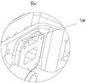
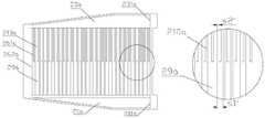
- Figure 3is an enlarged schematic view of P in Figure 2;
- Figure 4is another perspective view of the electric heater
- Figure 5is a cross-sectional view of the electric heater of Figure 4 taken along the M-M direction;
- Figure 6is an enlarged schematic view of N in Figure 5;
- Figure 7is a schematic cross-sectional view showing an embodiment of a protruding structure
- Figure 8is a schematic cross-sectional view showing another embodiment of the protruding structure
- Figure 9is a perspective view showing the angle of the partition of Figure 2;
- Figure 10is a perspective view showing the angle of the housing body and related parts of Figure 2;
- Figure 11is an enlarged schematic view of L in Figure 10;
- Figure 12is a perspective view of the housing body and related parts of Figure 2;
- Figure 13is a perspective view showing the structure of the heating pipe of Figure 2;
- Figure 14is a perspective view showing the angle of the cover body of Figure 2;
- Figure 15is a perspective view showing another perspective of the cover body of Figure 2;
- Figure 16is an enlarged schematic view of K in Figure 15;
- Figure 17is a schematic view showing an electrical connection manner between a thermal fuse and a heating element
- Figure 18is a schematic view showing another electrical connection manner between the thermal fuse and the heating element
- Figure 19is a schematic view showing still another electrical connection manner between the thermal fuse and the heating element
- Figure 20is a perspective view showing a first embodiment of a heat conducting portion and a related portion
- Figure 21is a schematic view showing another embodiment of the heat conducting portion and related portions
- Figure 22is a perspective view showing a second embodiment of the heat conducting portion and the related portion
- Figure 23is a perspective view showing a third embodiment of a heat conducting portion and a related portion
- Figure 24is a perspective view, partially enlarged schematic view showing a fourth embodiment of the heat conducting portion and the related portion;
- Figure 25is a perspective structural view showing another embodiment of the fourth embodiment of the heat conducting portion and the related portion;
- Figure 26is a partial schematic view of the heat conducting portion and related portions of Figure 25;
- Figure 27is a partial, fragmentary structural view of a second embodiment of an electric heater
- Figure 28is a schematic cross-sectional view of the inlet pipe of Figure 27.
- the electric heatercan convert electric energy into heat energy, and is suitable for heating a working medium in a liquid or vapor-liquid mixture state.
- the heating meansenergizes the electric heater by energizing, so that the heating element is heated to generate heat and heat the working medium.
- Electric heaterscan be used in applications where heating is required, such as vehicles or other mobile equipment, for heating or warming up.
- an electric heater 100including a heating element 6, a control module 5, a conductive element 31 and a partition 3, the heating element 6 is electrically connected to the control module 5, the conductive element 31, and the partition 3
- the control module 5is fixedly disposed
- the partitionis made of an insulating material
- the partition 3includes a partition base
- the partition baseincludes a partition first side portion 311 and a partition second side portion 312, and the partition first side portion 311 faces the control module.
- the second side portion 312 of the partition portionfaces away from the control module 5
- the conductive element 31is at least partially located between the first side portion 311 of the partition portion and the second side portion 312 of the partition portion.
- the first side portion 311 of the partition portionfaces the control module 5 .
- the spacer baseincludes a plate portion 32.
- the plate portion 32is at least partially disposed corresponding to the electronic control board.
- the conductive member 32includes a first conductive contact portion 311 and a second conductive contact portion 312, and the first conductive contact portion 311 and the heating element 6 fixedly disposed, the second conductive contact portion 312 is electrically connected to the control module 5, and the second conductive contact portion is located at the plate portion.
- the insulating material of the partition 3is beneficial to reduce the possibility of leakage of the control module 5 and other components, and is beneficial to improving the safety of the electric heater.
- the insulating materialis a material that is non-conductive under the allowable voltage, but is not absolutely non-conductive.
- the materialdefines the electrical resistivity of the insulating material in the range of 1010 to 1022 ⁇ m.
- the partition 3is made of a polymer material such as nylon, plastic, or the like, or the partition 3 is made of an inorganic non-metal material such as ceramics.
- the plate portion 32is disposed at least partially corresponding to the electronic control board, which facilitates the isolation of the other components from the control module 5, which is beneficial to the safety performance of the electric heater.
- the control module 5as a control component for controlling the operation of the electric heater, can receive a control signal from the vehicle control center, a drive module that is supplied to the electric heater through processing operations, and can store the operating parameters of the electric heater itself and feed back to
- the vehicle control centerthe vehicle control center involved in the present application may be a vehicle total control system or a vehicle air conditioning control system.
- the electric heater 100includes a first safety distance
- the control module 5includes a first electronic control board body portion, the first electronic control board body portion faces the partition portion 3, and the first safety distance refers to the first portion 311 of the partition portion and the first portion
- the distance between the main body of the electronic control boardis greater than 2 mm; or the electronic control board includes a first electronic control board body portion, the first electronic control board body portion faces the partition portion, and the first side portion 311 of the partition portion
- the first electronic control board body portionis not in direct contact.
- the first safety distanceis greater than 6 mm, or the first side portion 311 of the partition is not in direct contact with the first electronic control board body portion.
- air insulationis formed between the control module 5 and the partition portion 3, which is beneficial to electricity.
- the safety performance of the heaterprovides space for the second conductive contact 312 to be electrically connected to the control module 5.
- the heating element 6is a heating tube, and the heating tube 6 has the advantages of a high heating speed and the like.
- the partition baseincludes a bent portion 33.
- the plate portion 32is integrally provided with the bent portion 33.
- the bent portion 33extends along the plate portion and is bent toward the heating tube 6, and the first conductive contact portion 311 is located at the bend.
- the heating tubeincludes a heating tube contact portion 62, and the first conductive contact portion 311 is fixedly disposed with the heating tube contact portion 62.
- the plate portion 32is integrally provided with the bent portion 33, and can be integrally injection molded or the like.
- the processis relatively simple, and the arrangement of the bent portion 33 is advantageous for reducing the possibility of leakage of the portion of the first conductive contact portion 311 and other components. Conducive to the safety of the electric heater 100, in particular, the first conductive contact portion 311 is soldered to the heating tube contact portion 62 such that when the electric heater 100 applies a voltage, the conductive member 31 is electrically connected
- the partition 3includes a protruding portion 331, and the protruding portion 331 is located at the bent portion 33.
- the electric heater 100includes a fluid chamber 2, and the first conductive contact portion 311 is closer to the fluid chamber 2 than the protruding portion 331, the first conductive contact portion
- the 311includes a first top end, and the protruding portion includes a second top end 3311 that is away from the plate portion 32 than the first top end in a direction perpendicular to the plate portion.
- the first conductive contact portion 311is closer to the fluid chamber 2 than the protruding portion 331, which facilitates leakage of electricity between the first conductive contact portion 311 and other components such as the second sidewall 1211, thereby improving the electric heater 100.
- the second top end 3311is away from the plate portion 32 than the first end portion, which is advantageous for reducing the possibility of electric leakage between the first conductive contact portion 311 and other components such as the second housing 13. Conducive to the safety performance of the electric heater 100.
- the plate-like portion 32 and the bent portion 33are made of a polymer material or an inorganic non-metal material.
- the polymer material or the inorganic non-metal materialhas an insulating function, and on the other hand, has a flame-retardant function, which is advantageous for the safety performance of the electric heater 100.
- the second conductive contact portion 312is soldered and fixed to the control module 5.
- the partition portion 3includes at least one contact groove 324.
- the contact groove 324is located at the first side portion of the partition portion, and the conductive element 31 is partially located at the contact groove 324.
- the partition portion 3includes at least one plug.
- the receiving hole 325is located at the second side of the partition, the conductive element 31 is partially located at the insertion hole 325, and the contact groove 324 is at least partially corresponding to the position of the insertion hole 325, and the number of the contact groove 324 and the insertion hole 325 is set.
- the contact groove 324is connected to the insertion hole 325.
- the arrangement of the contact groove 324 and the insertion hole 325provides a possibility for the thermal fuse 249 of the electric heater 100 to be electrically connected to the conductive element 31, and on the other hand, it is advantageous to fix the temperature fuse 249.
- the electric heaterincludes a cover body 24 and a temperature fuse 249, wherein the cover body 24 includes a cover body wall, and one side wall of the cover body 24 is defined as a cover body wall, and the cover body 24 is located between the fluid chamber 2 and the partition portion 3, A part of the cover body 24 is a part of the wall portion forming the fluid chamber 2, the partition portion 3 is fixedly disposed with the cover body 24, the temperature fuse 249 is located between the cover body 24 and the partition portion 3, and the temperature fuse 249 includes a temperature fuse fixing portion and a temperature fuse.
- the fixing portionextends into the insertion hole 245, and the temperature fuse fixing portion is fixedly disposed with the conductive member 31, so that when the voltage is applied to the electric heater 100, the temperature fuse 249 is electrically connected to the conductive member 31, and the temperature fuse 249 has a function of protecting the circuit.
- the temperature fuse 249can prevent the electric heater 100 from dry burning, improve the safety and reliability of the electric heater 100, and the conductive element 31 is electrically connected to the temperature fuse 249, so that the temperature fuse 249 can be electrically connected to the heating element 6, and further
- the energized state of the temperature fuse 249can affect the energization state of the heating element 6.
- the electric heaterincludes a second side wall 1211 and a first side wall 1210.
- the second side wall 1211is at least partially out of contact with the first side wall 1210.
- the cover body 24is sealingly fixed with the first side wall 1210.
- the heating tube contact portion 62Located between the second sidewall 1211 and the first sidewall 1210, the first conductive contact portion 311 is located between the first sidewall 1210 and the protrusion portion 331, and the protrusion portion 331 is located at the second sidewall 1211 and the first sidewall
- the first conductive contact portion 311is not in contact with the first sidewall 1210, and the second sidewall 1211 is at least partially out of contact with the first sidewall 1210, so that the electric heater 100 forms an installation space, and the installation space includes the second The space between the side wall 1211 and the first side wall 1210, the installation space may provide a mounting space for the fixing of the high electric part 71, the weak electric part 72 and the control module 5, and the first conductive contact part 311 is not in contact with the
- the electric heaterincludes a strong electric portion 71 and a weak electric portion 72.
- the weak electric portion 72is at least partially located in the mounting area, and the second side wall includes a convex portion 12111.
- the convex portion 12111is disposed opposite to the fluid chamber, and the weak electric portion 72 and the convex portion are provided.
- the convex portion 12111corresponds to the arrangement, the convex portion 12111 includes a convex portion first portion 1211a, a convex portion second portion 1211b, and a convex portion third portion 1211c, and the convex portion second portion 1211b is located at the convex portion first portion 1211a and convex portion Between the third portion 1211c of the upper portion, the mounting area includes a space formed by the raised portion first portion 1211a, the raised portion second portion 1211b, and the raised portion third portion 1211c.
- the raised portion second portion 1211bis disposed in parallel with the first side wall 1210.
- the raised portion first portion 1211ais disposed perpendicular to the first side wall 1210
- the raised portion third portion 1211cis disposed perpendicular to the first side wall 1210.
- the portion 71is fixedly disposed with the second side wall 1211.
- the raised portion third portion 1211cis closer to the high-power portion 71 than the raised portion second portion 1211b, and the high-voltage portion is electrically connected to the control module and the heating element.
- the strong electric part 71can be used to connect the external strengthening voltage, the external strengthening voltage is generally greater than or equal to 200 volts, the weak electric part can be used to connect the applied weak voltage, and the external weak voltage is generally less than or equal to 90 volts.
- the electric heater 100includes an adapter plate 721.
- the adapter plate 721is electrically connected to the weak current portion 72.
- the adapter plate 721is electrically connected to the control module 5.
- the adapter plate 721includes an adapter hole, a lead end, and an adapter plate body 7211.
- the transfer hole and the weak electric partare fixedly arranged, and the lead end protrudes from the adapter plate as a cantilever, and the lead end is fixedly set with the electric control board/weak electric part.
- the weak current portion 72can be electrically connected to the control module 5 through the adapter plate 721, and the use of the wire can be reduced by the weak current plate 721, so that the structure of the electric heater 100 is simpler than that of the electric heater having the wire.
- the heating element 6is a heating tube
- the housing body 12is integrally formed with the heating tube.
- the structureis simple on the one hand, and on the other hand, the housing body 12 is integrally formed with the heating tube, and the housing body is integrally formed. A portion of 12 is at least partially enclosed outside the heating tube to provide a certain protection to the heating tube.
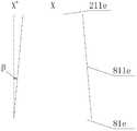
- the electric heaterincludes an inlet 81 and an outlet 82.
- the inlet 81 and the outlet 82are located on the same side of the electric heater 100.
- the inlet 81 and the outlet 82are located on the same side of the electric heater 100 as the electromotive portion 71 and the weak electric portion 72.
- the strong electric part 71 and the weak electric part 72are located on the same side of the electric heater 100, and are conveniently connected with a strong voltage and a weak voltage in the vehicle.
- the inlet 81 and the outlet 82are located on the same side of the electric heater 100, facilitating work in the vehicle.
- the medium input unit and the output unitare connected.
- an electric heater 100that can be applied to a place requiring heating, such as a vehicle or other mobile device, including a first wall 121, a heating element 6, a heat transfer wall 122, and
- the cover body 24includes a cover body wall.
- One side wall of the cover body 24is defined as a cover body wall.
- the heat transfer wall 122 and the cover body 24are fixedly connected or integrally formed with the first wall 121.
- the electric heaterincludes a fluid.
- the cavity 2, the inlet 81 and the outlet 82communicate with the inlet 81 and the outlet 82.
- the heat transfer wall 122includes a first side of the heat transfer wall, and the first wall and the first side of the heat transfer wall form a part of the wall forming the fluid chamber.
- the first side 1221 of the heat transfer wallfaces the fluid chamber 2, and the portion of the heating element 6 that is in contact with the heat transfer wall 122 is not in communication with the fluid chamber 2.
- the electric heater 100includes a heat dissipating portion 244, and the heat dissipating portion 244 and the cover body 24 In a fixed arrangement, the heat dissipating portion 244 protrudes from the cover body 24 to be cantilevered, the heat dissipating portion 244 faces the fluid chamber 2, the electric heater 100 includes the driving module 4, the driving module 4 and the cover body 24 are fixedly disposed, and the driving module 4 and the heat dissipating portion 244 are fixed.
- the driving module 4 and the heat dissipation portion 244are It is set corresponding to.
- the heat dissipating portion 244 and the driving module 4are located at two sides of the cover body 24, and the heat dissipating portion 244, the driving module 4 and the cover body 24 are fixedly disposed, and the heat dissipating portion 244 is disposed corresponding to the position portion of the driving module 4, when the electric heater is working.
- the heat dissipating portion 244is located in the working medium, and the temperature of the working medium 244 is lower than the temperature of the driving module 4.
- the heat dissipating portion 244can carry away a part of the heat generated by the driving module 4 by transferring heat to the working medium, thereby relatively extending the driving. The usage time of the module.
- the electric heater 100includes a fluid chamber inlet 211 and a fluid chamber outlet 231.
- the fluid chamber inlet 211is in communication with the inlet 81.
- the fluid chamber outlet 82is in communication with the outlet 82.
- the heat sink portion 244is closer to the fluid chamber than the fluid chamber outlet 82.
- the inlet 211has a heat dissipating portion free end 2441, and the heat dissipating portion free end 2441 is not in full contact with the heat transfer wall 122.
- the free end portion 2441 of the heat dissipating portionis not completely in contact with the heat transfer wall 122, which is advantageous for reducing the flow resistance of the working medium and facilitating the heating efficiency of the electric heater 100. .
- the cover body 244includes a strip-shaped protrusion 245, and the strip-shaped protrusion 245 is disposed to protrude away from the fluid chamber 2.
- the position of the strip-shaped protrusion 245is corresponding to the positional portion of the heat-dissipating portion 244, and the position of the driving module 4 and the strip-shaped protrusion are provided.
- a portion of the 245is correspondingly disposed, and the driving module uses an insulated gate bipolar transistor module or a metal-oxide semiconductor field effect transistor module; wherein the strip protrusions 245 facilitate the close contact between the driving module 4 and the cover body 24, and the strip protrusions 245 facilitates transferring heat of the drive module 4 to the heat sink 244.
- the electric heater 100includes a thermally conductive insulating member between the driving module 4 and the cover 24, and the thermally conductive insulating member facilitates heat transfer from the driving module 4 to the strip-shaped projections 245.
- the electric heaterincludes a heat conducting portion 26 between the heat transfer wall 122 and the cover body 24.
- the electric heaterincludes a first current collecting portion 21, a second current collecting portion 23, and a heating passage, and the first current collecting portion 21
- the fluid chamber inlet 211 and the heating channelare connected, and the second current collecting area is connected to the fluid chamber outlet 231 and the heating channel.
- the heat conducting portion 26is advantageous for increasing the heating contact area of the working medium, thereby facilitating the heating efficiency of the electric heater 100.
- the electric heater 100includes a flow guiding portion 27 between the cover body 24 and the heat transfer wall 122. Compared with the heat dissipating portion 244, the flow guiding portion 27 is closer to the fluid chamber inlet 211 than the heat dissipating portion 244, and the diversion is performed.
- the portion 27includes a flow guiding portion fixing portion 271 and a guiding portion free end 272.
- the guiding portion 27is fixedly disposed with the cover body 24 or the heat transfer wall 122.
- the flow guiding portion 27includes at least a first flow guiding surface 273, and the first guiding flow.
- the surface 273has an angle with the fluid chamber inlet 211, and the first flow guiding surface 273 and the fluid chamber inlet 211 are heated to 30 degrees to 60 degrees;
- the flow guiding portion fixing portion 271is fixedly disposed with the cover body 24, the free portion 272 of the guiding portion is not in contact with the heat transfer wall 122, and the flow guiding portion includes the second flow guiding surface 274 and the third flow guiding surface 275, first The second and third flow guiding surfaces are sequentially connected, the second flow guiding surface 274 and the third flow guiding surface 275 have an angle, and the angle between the second guiding surface and the third guiding surface is less than 45 degrees;
- the flow guiding portion fixing portion 271is fixedly disposed with the heat transfer wall 122, the free portion 272 of the flow guiding portion is not in contact with the lid body 24, and the flow guiding portion 27 includes the second flow guiding surface 274 and the third flow guiding surface 275,
- the second and third flow guiding surfacesare sequentially connected, the second guiding surface and the third guiding surface have an angle, and the angle between the second guiding surface and the third guiding surface is less than 45 degrees.
- the flow guiding portion 27can play a role of drainage on the working medium, and can promote the uniform distribution of the working medium in the fluid cavity to a certain extent. Specifically, the working medium enters the fluid chamber through the inlet and reaches the first collecting area.
- the fluid chamberWhen the flow guiding portion 27 is not provided, due to the dynamics of the working medium, the fluid chamber may be in the vicinity of the inlet portion, or the working medium may be generated or In the case where the working medium is small, in order to reduce the occurrence of such a situation, the flow guiding portion 27 is provided.
- the heat dissipating portion 244includes a heat dissipating portion fixing portion 2442 and a heat dissipating portion free end 2441.
- the heat dissipating portionis formed in a columnar shape or an elliptical column shape from the fixing portion 2442 to the end portion of the heat dissipating portion 2441.
- the heat dissipating portionis fixed in a columnar shape or an elliptical column shape from the fixing portion 2442.
- the extension of the free end 2441is relatively advantageous to reduce the resistance of the heat sink to the working medium.
- the electric heaterincludes at least three heat dissipating portions 244, and the adjacent two heat dissipating portions have a center-to-center distance, and the center distance between two adjacent heat dissipating portions refers to the distance between the centers of the bottom surfaces of the adjacent two heat dissipating portions, and the adjacent two heat dissipating portions
- the center distance rangeis 4-7mm, and the number of heat dissipation parts ranges from 35 to 120.
- the distance between the two adjacent heat dissipating portionsis 4-7 mm, and the number of the heat dissipating portions is 35-120, which is beneficial to the heat dissipation of the driving module 4 to a certain extent, and is advantageous for relatively reducing the heat dissipating portion. 244 resistance to working medium.
- the electric heaterincludes a first area, the first area refers to a contact area of the driving module and the cover body or a projected area of the driving module to the cover body, the electric heater includes a second area, and the second area refers to the heat dissipation part and the cover body.
- the area of contact, the second areahas a ratio with the first area, and the ratio of the second area to the first area to the first area is 3-4.5, wherein the ratio of the second area to the first area to the first area is 3-4.5.
- the heat dissipating portionis made of a metal material
- the lid bodyis made of a metal material
- the heat transfer wall and the first wallare made of a metal material
- the heat transfer wallis integrally formed with the first wall.
- the electric heater 100includes a partition 3 and a control module 5 .
- the partition 3is at least partially located between the control module 5 and the cover 24 .
- the partition 3is fixedly disposed with the cover 24 and the control module 5 , and the electric heater 100 includes The conductive element 31, the conductive element 31 is electrically connected to the heating element 6 and the control module 5, and the partition 3 is made of an insulating material;
- the electric heater 100comprises a circuit board 92, a partition 3 and a control module 5, the circuit
- the plate 92 and the fluid chamber 2are located on both sides of the heating element 6, the partition 3 is located between the cover 24 and the control module 5, the partition 3 is made of an insulating material, and the circuit board 92 is electrically connected to the heating element 6 and the control module 5.
- the partition 3is made of an insulating material, which is advantageous for avoiding the risk of leakage between the control module 5 and the cover 24, thereby facilitating the safety of the electric heater.
- an electric heater 100which can be applied to a place requiring heating, such as a vehicle or other mobile device, including a heat transfer wall 122, a heating element 6, and a heat transfer portion 26,
- the hot wall 122includes a first side surface 1221 of the heat transfer wall, the first side surface 1221 of the heat transfer wall faces the fluid chamber 2, the first side surface 1221 of the heat transfer wall is a part of the wall portion forming the fluid chamber, and the heating element 6 is located away from the heat transfer wall 122.
- the portion of the heating element 6 that is in contact with the heat transfer wall 122is not in communication with the fluid chamber 2, and the electric heater 100 includes a fluid chamber 2, an inlet 81, and an outlet 82.
- the fluid chamber 2is connected to the inlet 81 and the outlet 82.
- the fluid chamber 2includes a fluid chamber inlet 211, a fluid chamber outlet 231, a heating channel, a first current collecting portion 21, and a second current collecting portion 23.
- the first current collecting portion 21acommunicates with the fluid chamber inlet 211a and the heating channel
- second The current collecting portion 23acommunicates with the heating channel and the fluid chamber outlet
- the first current collecting portion 21acommunicates with the second current collecting portion 23a.
- the heat conducting portionincludes a first heat conducting portion 261a and a second heat conducting portion 262a, and the first heat conducting portion 261a is located at the first heat conducting portion 261a.
- first and second heat conducting portions 262arelatively increase the heating contact area of the working medium, and the heat conducting portion is provided to facilitate the increase of the efficiency of the electric heater with respect to the case where the heat conducting portion is not disposed.
- the first current collecting area 21ais disposed in parallel with the second current collecting area 23a.
- the electric heaterincludes a first heating area 29a and a second heating area 210a.
- the heating channelhas a channel spacing, and the first heating zone channel spacing is larger than the second heating zone channel.
- the first heating zone 29ais located closer to the first current collecting zone than the second heating zone 210, the first heat conducting portion 261a is located in the second heating zone 210a, and the second heat conducting portion 262a is partially located in the first heating zone 29a, the second heat conducting portion The portion 262a is located in the second heating zone 210.
- the arrangementis such that when the working medium flows from the first heating zone 29a to the second heating zone 210a, the cross-sectional area of the heating channel is reduced, which is favorable for uniform heating of the working medium;
- the flow cross-sectional area of the first current collecting portion 21a away from the end of the fluid chamber inlet 211ais smaller than the flow cross-sectional area of the fluid chamber inlet 211a of the first current collecting portion 21a, and the second current collecting portion 23a is away from the end of the fluid chamber outlet 231a.
- the flow cross-sectional areais smaller than the flow cross-sectional area of the fluid chamber outlet of the second current collecting portion 23a.
- the flow cross-sectional area of the first current collecting portion 21a away from the fluid chamber inlet 211ais smaller than the flow cross-sectional area of the fluid chamber inlet 211a of the first current collecting portion 21a, which is beneficial to reduce or avoid the first current collecting portion 21a away from the fluid chamber inlet 211a.
- the retention of the working medium at one endis advantageous for the heating efficiency; the flow cross-sectional area of the second current collecting portion 23a away from the end of the fluid chamber outlet 231a is smaller than the flow cross-sectional area of the fluid chamber outlet of the second collecting portion 23a, which is beneficial to reduce or avoid the second
- the retention of the working medium of the header 23 away from the end of the fluid chamber outlet 231afacilitates heating efficiency.
- the first heat conducting portion 261ais spaced apart from the second heat conducting portion 262a.
- the first and second forming surfacesare planar, and the forming surface is disposed perpendicular to the first collecting region and the second collecting region, and the first heat conducting portion 261a and the second heat conducting portion are disposed.
- the portion 262ais disposed in parallel, the first heating zone has a first channel spacing, the second heating zone has a second channel spacing, and the first channel spacing is greater than or equal to 2 times the spacing of the second channel, so that the heating of the working medium is uniform;
- first heat conducting portion 261a and the second heat conducting portion 262aare not spaced apart, and the first forming surface is a plane, and the first forming surface is perpendicular to the first collecting portion 21a and the second collecting portion 23a.
- the second heat conducting portionincludes a transition portion, the adjacent second heat conducting portions are symmetrically disposed, the second heat conducting portion includes a first portion and a second portion, the transition portion is located between the first portion and the second portion, and the first portion is located in the first collecting portion, the first portion
- the second partis located in the second current collecting area, the first part comprises two symmetrical second forming faces, the second part comprises two symmetrical third forming faces, and the second and third forming faces are plane, adjacent first The second and third constituent faces are disposed in parallel, and the first, second, and third constituent faces are disposed perpendicular to the first collecting region, the first heating region has a first channel spacing, and the second heating region has a second channel spacing.
- the spacing of the first channelis greater than or equal to the spacing of the second channel, which is less than twice the spacing of the second channel. This arrangement is advantageous for uniform heating of the working medium.
- the first heating zone 29ais adjacent to the channel spacing between the first and second heat conducting portions, and/or the second heating zone 210a is adjacent to the channel spacing between the second heat conducting portions, so as to facilitate the working medium. Uniform flow, which is conducive to uniform heating of the working medium;
- first heating zone 29bis adjacent to the first and second heat conducting portions (261b, 262b), the adjacent second heat conducting portion 262b has a channel spacing equal to, and/or the second heating zone 210b phase
- the channel spacing between the adjacent second heat conducting portions 262bis equal, and the arrangement is favorable for uniform flow of the working medium and is favorable for uniform heating of the working medium.
- an electric heater 100 for an electric vehicleincluding a heat transfer wall 122, a heating element 6, and a heat transfer portion 26, the heat transfer wall 122 including a first side surface 1221 of the heat transfer wall
- the first side surface 1221 of the heat transfer wallfaces the fluid chamber 2
- the first side surface 1221 of the heat transfer wallis a part of the wall portion forming the fluid chamber 2
- the heating element 6is located on the side of the heat transfer wall 122 facing away from the fluid chamber 2, the heating element 6
- the portion in contact with the heat transfer wall 122is not in communication with the fluid chamber 2
- the electric heaterincludes a fluid chamber 2, an inlet 81, and an outlet 82.
- the fluid chamber 2is in communication with the inlet 81 and the outlet 82.
- the fluid chamberincludes a fluid chamber inlet 81 and a fluid.
- the first current collecting area 21is in communication with the second current collecting area 23, and the heat conducting portion includes at least two first heat conducting portions 261, and a space between the adjacent first heat conducting portions 261 is a component of the heating channel.
- the heat conducting portion 261relatively increases the heating contact area of the working medium, and the heat conducting portion 261 is provided to facilitate increasing the heating efficiency of the electric heater 100 with respect to the case where the heat conducting portion 261 is not disposed;
- the first heat conducting portion 261includes two symmetrical forming faces, the forming surface is a part of the wall portion forming the heating channel, the forming surface is a plane/curved surface, the forming surface has an angle with the first collecting region, and at least one constituent surface and the first surface The angle of the collecting region is greater than 0 degrees and less than or equal to 90 degrees, and the forming surface has an angle with the second collecting region, and the angle between the at least one constituent surface and the second collecting region is greater than 0 degrees and less than or equal to 90 degrees.
- the arrangementis favorable for the uniform flow of the working medium and is favorable for uniform heating of the working medium.
- the heating channelhas a channel spacing, adjacent to the first heat conducting portion 261, the electric heater includes a first heating zone 29 and a second heating zone 210, the first heating zone 29 has a first channel spacing, and the second heating zone has a second The channel spacing 210, the first channel spacing is greater than or equal to the second channel spacing, and the first heating zone 29 is closer to the first current collecting zone than the second heating zone 210. So, in the first heating zone 29, the temperature difference between the working medium and the heat transfer wall 122 is relatively large.
- the temperature difference between the working medium and the heat transfer wall 122is relatively small, and the first channel spacing is greater than or equal to the first The two-channel spacing, the residence time of the working medium in the first heating zone is greater than the residence time in the second heating zone, which is favorable for uniform heating of the working medium.
- the electric heater 100includes a third current collecting area 28, the third current collecting area 28 is disposed in parallel with the first current collecting area 21, the third current collecting area 28 is disposed in parallel with the second current collecting area 23, and the third current collecting area 28 is provided.
- the first heating zone 29 and the second heating zone 210are connected, the third current collecting zone 28 is in communication with the first collecting zone 21, and the third current collecting zone 28 is in communication with the second collecting zone 23.
- the heatingis continued into the second heating zone 210, which is favorable for uniform heating of the working medium, thereby facilitating the electric heater 100. Heating efficiency.
- the first heat transfer portion 261/261a and the second heat transfer portion 262aare made of a metal material, and the heat transfer wall 122 is made of a metal material.
- the heat transfer wall 122, the first heat transfer portion 261/261a, and the second heat transfer portion 262aare integrally formed. With this setup, the structure is relatively simple.
- the electric heater 100includes a cover body 24 and a first wall 121.
- the cover body 24is fixedly disposed with the first wall 121.
- the fluid chamber 2 and the heating element 6are located on the same side of the cover body 24.
- the heat transfer portion 26is located at the heat transfer wall 122 and the cover.
- the electric heater 100includes a second side wall 1211.
- the first wallincludes a first side wall 1210.
- the second side wall 1211is at least partially out of contact with the first side wall 1210.
- the electric heater 100includes a first housing 11 , a second housing 13 , a housing body 12 , and a protruding structure 116 .
- the protruding structure 116is at least partially located in the first housing 11 , the housing body 12 , and the second housing. Between the housing body 12 and the housing body 12, the protruding structure 116 includes a protruding structure fixing portion 1161 and a protruding structure free end 1162.
- the protruding structure fixing portion 1161is combined with the first housing 11 and/or the second housing 13 and/ Or the housing body 12 is fixedly disposed.
- the protruding structure 116maintains a certain distance between the first housing 11 and the housing body 12, and between the second housing 13 and the housing body 12. When the mounting is performed, due to the presence of the protruding structure 116, The force between the first housing 11 and the housing body 12 is relatively uniform.
- the electric heater 100includes a vent hole 9 in which the vent hole 9 is located, the vent hole 9 penetrates the first housing 11, the vent hole 9 does not communicate with the fluid chamber 2, or the vent hole 9 is located at the second
- the casing 13has a vent hole 9 penetrating the second casing 13, and the vent hole 9 is not in communication with the fluid chamber 2; or the vent hole 9 is located in the casing body 12, the vent hole 9 penetrates the casing body 12, the vent hole 9 and the fluid The cavity 2 is not connected.
- the vent hole 9has a function of keeping the pressure inside and outside the electric heater 100 uniform.
- the vent hole 9is provided with a vent film for relative sealing, which allows air to pass through without passing water or other medium, and the film has a simple and convenient function.
- the vent holemay also be sealed by a sealing plug, and a rubber plug or the like may be used for the sealing plug, and the sealing plug also has a function of keeping the internal and external pressures of the electric heater 100 consistent.
- FIGS. 1 - 26are a first embodiment of an electric heater.
- the electric heater 100includes a housing 1, a fluid chamber 2, a partition 3, a driving module 4, a control module 5, a heating element 6, a wiring portion 7, and an inlet 81 and an outlet 82.
- the electric heater 100is electrically supplied to the heating element. 6 heats up and heats the working medium in the fluid chamber 2.
- the housing 1includes a first housing 11, a housing body 12, and a second housing 13. The first and second housings are sealed and fixed to the housing body.
- the electric heater 100includes a mounting space, and the installation space includes a first a space formed by the housing body and the second housing, the fluid chamber 2, the partition 3, the driving module 4, the control module 5, and the heating element 6 are located in the mounting cavity, the partition 3, the driving module 4, the control module 5, and the heating element 6 electrically connected, the control module 5 as a control component for controlling the operation of the electric heater, can receive a control signal from the vehicle control center, a drive module that is supplied to the electric heater through processing operations, and can store operating parameters of the electric heater itself, And feedback to the vehicle control center, the vehicle control center involved in the present application may be a vehicle total control system or a vehicle air conditioning control system.
- the electric heater 100includes a heating element 6, a heat transfer wall 122, and a control module 5.
- the electric heaterincludes a fluid chamber 2, an inlet 81, and an outlet 82.
- the fluid chamber 2communicates with the inlet 81 and the outlet 82.
- the hot wall 122is a part of the wall portion forming the fluid chamber 2, the heating element 6 is fixed or limited to at least part of the heat transfer wall 122, and the heating element 6 is located outside the fluid chamber 2, at least part of the heating element 6 is in contact with the heat transfer wall 122.
- the cover wall of the electric heater 100is a further wall portion forming a fluid chamber, the control module 5 is located outside the cover wall, and the control module is located outside the fluid chamber 2, and the control module 5 is electrically connected to the heating element 6.
- the first side surface 242 of the cover wall of the cover wallfaces the fluid cavity
- the first side 242 of the cover wallfaces the first side surface 1221 of the heat transfer wall
- the control module 5is located at the first side 1221 of the cover wall.
- the back side of the cover body, the first side 242 of the cover body wallis in direct contact with the working medium, and the heating element 6 and the fluid chamber 2 are not on the same side with respect to the first side surface 1221 of the heat transfer wall, so as to prevent the heating element 6 from directly contacting the working medium.
- control module 5is located on the opposite side of the first side 1221 of the cover wall, and the control module 5 is arranged without contact.
- the side of the working medium, and the control module 5is located outside the fluid chamber 2, relatively reducing the influence of the heat generated by the heating element 6 on the control module 5, such as relatively reducing the damage of the control module 5 due to heat.
- the housing 1includes a first housing 11, a housing body 12, and a second housing 13.
- the first and second housingsmay be press-formed with a metal material to support and protect.
- a metal materialSpecifically, aluminum can be used for press forming, and the aluminum material has a small density, so that it has the advantage of light weight at the same volume.
- the first and second housingsare respectively fixedly and fixedly disposed with the housing body 12, and the fixed arrangement here and the following fixed settings include a direct fixed setting and a relatively fixed setting.
- the direct fixing arrangementrefers to a form in which the components to be fixed are fixed to each other or in a unitary structure, for example, two or more components are fixed to each other by bolts, two or more components are fixed to each other by welding, two or more.
- the componentis fixedly arranged by its own structure (such as plugging) or other means, and two or more components are fixedly arranged by integral forming; the relatively fixed setting means that the components that need to be fixed can be fixed by fixing with the reference object to achieve the need to be fixed.
- the componentsare relatively fixed.
- the two componentsare respectively fixed to the third component such that the two components are relatively fixed.
- the third componentis a reference object, and the reference object may include more than one.
- the first housing 11includes a first housing body 111, a first ridge 112, a first recess 113, a first fixing portion 114, and a first edge portion 115, wherein the first ridge 112 faces away from the housing body
- the direction of the protrusionis convexly disposed, and the first recessed portion 113 is convexly disposed toward the housing body 12, and the first raised portion 112 and the first recessed portion 113 contribute to increase the strength of the first housing 11.
- the first housing 11 and the housing body 12can be relatively fixed by the first fixing portion 114.
- the first edge portion 115is extended by the first housing body 111 and is bent toward the housing body 12, and the first edge portion 115 can be
- the first housing 11 and the housing body 12function as an initial fixing during the mounting and fixing process.
- the first housingmay not include the first edge portion.
- the housing body 12includes a first wall 121 and a heat transfer wall 122, at least a portion of which is disposed in contact with the heat transfer wall 122, where the contact arrangement includes direct contact settings and indirect contact settings.
- the direct contact arrangementfor example, at least part of the heating element 6 abuts the heat transfer wall 122
- the indirect contact arrangementfor example, an intermediate heat conductive material such as a heat conductive film or a heat conductive sheet is disposed between the heating element 6 and the heat transfer wall 122, and the heating element 6 At least part of the material abuts the intermediate heat conductive material, and the intermediate heat conductive material abuts the heat transfer wall.
- the heat transfer wall 122can transfer heat generated by the heating element 6 to the working medium, and the heat transfer wall 122 itself cannot generate heat; on the other hand, the heat transfer wall 122 separates the heating element 6 from the fluid chamber 2, or can be said to be
- the heating element 6is located outside the fluid chamber 2, or the area of the heat transfer wall 122 where the heating element 6 is located is not in communication with the fluid chamber 2, or it can be said that the heat transfer wall 122 is such that the heating element 6 is not in direct contact with the fluid chamber 2.
- the heat transfer wall 122is fixedly disposed with the first wall 121. Specifically, the heat transfer wall 122 is integrally formed with the first wall 121.
- the first wall 121has an angle with the heat transfer wall 122, and the angle is greater than zero.
- the first wall 121is disposed perpendicular to the heat transfer wall 122, where the vertical arrangement includes an error range of 0 to 10 degrees.
- the heat transfer wall 122has a heat transfer wall first side surface 1221, a heat transfer wall second side surface 1222, and a recess 1223, wherein the heat transfer wall first side surface 1221 faces the first housing 12, and the heat transfer wall first side surface 1221 is at least partially To form a portion of the wall of the fluid chamber or to say that the electric heater 100 is in operation, the first side 1221 of the heat transfer wall may be in direct contact with the working medium, the second side 1222 of the heat transfer wall facing away from the fluid chamber toward the second housing 13 When the electric heater 100 is in operation, the second side portion 1222 cannot be in contact with the working medium, and the groove 1223 is at least partially located between the first side portion 1221 and the second side portion 1222, or can be said to be the large groove 1223.
- the portionis located between the first side portion 1221 and the second side portion 1222, or it can be said that the groove 1223 is located between the first side portion 1221 and the second side portion 1222.
- the groove 1223is formed as a through hole. Or the form of the through channel.
- the heating element 6is a heating tube
- the recess 1223provides a space for the heating tube.
- the housing body 12does not include a recess.
- the heating elementis located on the second side of the heat transfer wall, and is disposed in contact with the second side of the heat transfer wall, or the heating element is an electric heating film, the electric heating film is attached or formed on the second side of the heat transfer wall, and the heat transfer wall
- the heat transfer wall 122transfers the heat generated by the heating element 6 to the first side surface 1221 of the heat transfer wall, and the working medium is heated by the first side portion 1221.
- the heat transfer wall 122can also transfer heat to the first wall 121, and the first wall 121 can also transfer heat to the working medium.
- the second housing 13includes a second housing body 131, a second raised portion 132, a second fixing portion 133, and a second edge portion 134, wherein the second raised portion 132 faces the housing body 12, and the second housing 13 and the housing
- the body body 12can be fixed by the second fixing portion 133, the second edge portion 134 is extended by the second housing body 131 and is bent toward the housing body 12, and the second edge portion 134 can be in the second housing 13 and the shell
- the body body 12functions as an initial fixing during the mounting and fixing process.
- the electric heater 100can be waterproof and dustproof by the sealing arrangement, or it can be said that the first housing 11 and the housing body 12 are sealed and fixed.
- the sealing and fixing between the second casing 13 and the casing body 12facilitates waterproof and dustproof of the electric heater 100.
- the electric heater 100includes a sealing member W located between at least the first housing 11 and the housing body 12, between the second housing 13 and the housing body 12, in particular, the sealing member W.
- the sealing material which is deformed according to the shape of the sealing surface,is not easy to flow, and has a certain adhesiveness, more specifically, the sealing member W is made of a sealing glue. Referring to FIG. 5 and FIG.
- the electric heater 100includes a protruding structure 116, the protruding structure 116 is located between the first housing 11 and the housing body 12, and/or the second housing 13
- the protruding structure 116includes a protruding structure fixing portion 1161 and a protruding structure free end 1162, the protruding structure fixing portion 1161 and the first housing 11 and/or the second housing 13 and/or the shell
- the body body 12is fixedly disposed, and the protruding structure free end 1162 is in direct contact with the first housing 11 and/or the second housing 13 and/or the housing body 12; the protruding structure fixing portion 1161 and the first housing 11 and / Or the contact area of the second housing 13 and/or the housing body 12 is the first contact area, and the protruding structure is free.
- the contact area of the end 1162 with the first housing 11 and/or the second housing 13 and/or the housing body 12is a second contact area, and the first contact area is greater than or equal to the second contact area, which can enhance the contact effect, so that
- the contact between a casing and other casingsis reliable, in particular, when the installation is performed, due to the presence of the protruding structure 116, the force between the first casing 11 and the casing body 12 is relatively uniform, reducing the local pressure.
- the problem caused by the oversizeis that there is no problem of the sealing member W.
- the protruding structure 116is integrally formed with the housing 1 , specifically, the protruding structure 116 is integrally formed with the first housing 11 , and/or the protruding structure 116 is integrally formed with the housing body 12 , and/or the protruding structure 116 Formed integrally with the second housing 13, the component structure is relatively simplified.
- the protruding structure 116includes a protruding structure fixing portion 1161 and a protruding structure free end 1162 .
- the protruding structure free end 1162is in contact with or abuts against the housing 1 , specifically, the protruding structure fixing portion 1161 and The first housing 11 is integrally formed, and the free end 1162 of the protruding structure is in contact with the housing body 12, or the protruding structure fixing portion 1161 is integrally formed with the housing body 12, and the free end 1162 of the protruding structure and the first housing 11 are protruded. Contact.
- the protruding structure 116is integrally formed with the first housing 11 .
- the protruding structure fixing portion 1161is integrally formed with the first housing 11 , and the free end of the protruding structure 1162 It is in contact with the housing body 12 such that there is a gap between the first housing 11 and the housing body 12.
- the sealing member Wis applied to the second housing 12, and the first housing 11 is fitted and pressed together with the housing body 12, in the process, redundant The sealing member W is pressed between the first edge portion 115 and the housing body 12.
- the housing body 12includes a second wall 120.
- the second wall 120is integrally formed with the first wall 121, and the second wall 120 can be sealed and fixed to the first housing 11.
- the housing body 12includes a first dividing wall, that is, a second side wall 1211, a second dividing wall 1212, a third dividing wall 1213, and a fourth dividing wall 1214.
- the second side wall 1211is disposed opposite to the third dividing wall 1213, and the second The partition wall 1212 is disposed opposite to the fourth partition wall 1214.
- the second side wall 1211is sealed and fixed to the high-voltage portion 71 and the weak electric portion 72.
- the second side wall 1211is a strong electric portion 71 and a weak electric portion. 72.
- the first housing 11includes a first side 117, a second side 118, a third side 119, and a fourth side 1110, wherein the first side 117 corresponds to the second side wall 1211, and the second side 118 and the second side wall Corresponding to 1212, the third side 119 corresponds to the third dividing wall 1213, and the fourth side 1110 corresponds to the fourth dividing wall 1214.
- the protruding structure 116is located at the first, second, third, and fourth sides, and specifically, at least one protruding structure 116 is disposed on the first, second, third, and fourth sides, respectively, when a protruding structure is disposed At 116 o'clock, the protruding structure 116 is located substantially at an intermediate position between the first, second, third, and fourth sides; more specifically, in order to make the sealing effect better, respectively in the first, second, third, and fourth At least three protruding structures 116 are disposed on the side, wherein at least one protruding structure is located at an intermediate position between the first, second, third, and fourth sides; and further, in the first, second, third, and At least one protruding structure 116 is disposed on four sides, and adjacent convex structures 116 are apart from each other by about 30 mm on the same side.
- the housing body 12includes a housing body outer portion 1215, a housing body inner portion 1216, and a first sealing surface 1217.
- the first sealing surface 1217is located between the housing body outer portion 1215 and the housing body inner portion 1216 and faces the first
- the first housing 11includes a second sealing surface 1111, the second sealing surface 1111 faces the housing body 12, and the protruding structure 116 is fixedly disposed with the second sealing surface 1111, wherein the first sealing surface 1217 and the second sealing surface Faces 1111 are collectively referred to as sealing faces.
- the protruding structure 116is located at least between the first housing 11 and the housing body 12, and the sealing element W is located at least between the first sealing surface 1217 and the second sealing surface 1111.
- the protruding structure 116is at least first. Between the sealing surface 1217 and the second sealing surface 1111, the protruding structure 116 is in contact with the sealing member W, and the circumferential side of the protruding structure 116 is in contact with the sealing member W. In the embodiment shown in FIG. 7 , the protruding structure fixing portion 1161 and the second sealing surface fixing 1111 are disposed, and the protruding structure free end 1162 is in contact with the first sealing surface 1217. As another embodiment, the protruding structure fixing portion is provided.
- the first sealing surfaceis fixedly disposed, and the free end of the protruding structure is in contact with the second sealing surface; or the electric heater comprises at least two protruding structures, and the partial protruding structure fixing portion is fixedly disposed with the first sealing surface, and the convex portion is partially convex.
- the free end of the structureis fixedly disposed with the second sealing surface.
- the protruding structureis integrally formed with the second sealing surface, that is, the protruding structure 116 is integrally formed with the first housing 11.
- the protruding structure fixing portionis fixedly disposed with the first sealing surface, that is, the protruding structure Formed integrally with the housing body, the free end of the protruding structure is in contact with the second sealing surface, or the electric heater comprises at least two protruding structures, and the partial protruding structure fixing portion is fixedly disposed with the first sealing surface, that is, partially protruding
- the structureis integrally formed with the housing body, and the partial protruding structure fixing portion is integrally formed with the second sealing surface, that is, the partial protruding structure is integrally formed with the first housing.
- the raised structure free end 1162is in surface contact with the first sealing face, and the protruding structure does not simultaneously intersect the housing body outer portion 1215 and the housing body inner portion 1216.
- the outer portion 1215 and the first contact surface 1217have two intersection lines, and the intersection line is a third boundary line and a fourth boundary line, that is, the first sealing surface includes a third boundary line and a fourth boundary line, specifically, the third The boundary line is disposed in parallel with the third boundary line, and the distance between the third boundary line and the fourth boundary line is a second parallel distance, and the protruding structure 116 is simultaneously intersected with the third boundary line and the fourth boundary line at the same time, similar to
- the second sealing surfaceincludes a first boundary line and a second boundary line.
- the protruding structureintersects the first boundary line and the second boundary line at different times.
- the first boundary lineis parallel to the second boundary line
- the first The distance between the boundary line and the second boundary lineis a first parallel distance.
- the protruding structure 116is substantially in the shape of a circular table
- the protruding structure fixing portion 1161is a lower bottom surface of the circular table
- the protruding structure free end 1162is an upper bottom surface of the circular table and is a curved surface.
- the convex structure free end 1162 and the first sealing surface 1217may adopt a single-sided contact and a non-single-sided contact, and the non-single-sided contact means that the convex structure free end 1162 and the first sealing surface 1217 intersect more than one surface.
- FIG. 7is a schematic cross-sectional view showing an embodiment of the point contact of the protruding structure. In the embodiment shown in FIG. 7, the free end of the protruding structure is in point contact with the sealing surface, and the protruding structure is used.
- the 116has a first contact area and a second contact area, wherein the first contact area refers to the area of the portion where the convex structure fixing portion 1161 intersects the second sealing surface, and the second contact area refers to the convex structure free end 1162 and the The area of the intersection of a sealing surface 1217, the first contact area being greater than or equal to the second contact area.
- the protruding structuresare different, they intersect the outer side of the housing body and the inner side of the housing body.
- the contact area of the free end of the protruding structureis smaller than or equal to the area occupied by the fixed portion of the protruding structure.
- the point contactmay be a single point contact and a non-single point contact, the point contact means that the intersection of the free end of the protruding structure and the sealing surface is a point, and the single point contact means that the intersection of the free end of the protruding structure and the sealing surface is a point.
- Non-single point contactrefers to a point where the free end of the protruding structure intersects the sealing surface by 2 or more.
- FIG. 8is a schematic cross-sectional view showing a convex structure of the line contact, and the convex structure is free. The end is in contact with the sealing surface by a line contact, and the protruding structure is different from the outer side of the housing body and the inner side of the housing body.
- the contact area of the free end of the strip-shaped protruding structureis smaller than or equal to the area occupied by the fixed portion of the strip-shaped protruding structure.
- the protruding structurehas a strip shape, and the line contact means that the free end of the protruding structure intersects the sealing surface.
- the partis a line segment or a curve having a certain length, wherein the line contact can be a single line contact and a non-single line contact, and the single line contact means that the free end of the protruding structure intersects the sealing surface as a line segment or a curve having a certain length, and is not a single line.
- the protruding structurehas a height, which refers to a vertical distance from the fixing portion of the protruding structure to the free end of the protruding structure, and the height of the protruding structure is greater than or equal to 0.5 mm. Specifically, the height of the protruding structure may be between 0.5 mm and 2 mm. .
- the sealing element Whas a width
- the sealing element widthrefers to a smaller value of the first parallel distance and the second parallel distance, that is, when the first parallel distance is greater than the second parallel distance, the sealing element width is equal to the second Parallel distance, when the first parallel distance is less than the second parallel distance, the sealing element width is equal to the first parallel distance, the sealing element width is greater than or equal to 5 mm, and specifically, the sealing element width is 5-10 mm.
- the second casing 13 and the casing body 12are also sealed together, and the sealing arrangement can be waterproof and dustproof.
- a sealing member Wis disposed between the second casing 13 and the casing body 12.
- the sealing arrangement between the second housing 13 and the housing body 12is similar to the sealing arrangement between the first housing 11 and the housing body 12.
- sealing member Wwhen the sealing member W is selected between the first housing and the housing body, the housing body and the second housing, the first housing and the housing body, the housing body and the second housing Screwed.
- the heating core of the electric heater 100is a heating element 6, and the electric heater 100 includes at least one heating element 6, the first side surface 1221 of the heat transfer wall faces the fluid chamber 2, and the heat transfer wall 122 is a part of the wall portion forming the fluid chamber, facing away from
- the heating element 6is located outside the fluid chamber 2, and at least the heating element 6 is disposed in contact with the heat transfer wall 122.
- the heating element 6is not on the same side as the fluid chamber 2 with respect to the first side surface 1221 of the heat transfer wall.
- the control module 5is located outside the fluid chamber, the control module 5 is located on the opposite side of the first side 242 of the cover wall, and the control module 5 is electrically connected to the heating element 6.
- the heating element 6is located on the same side of the cover 24 as the fluid chamber 2, in particular the heating element 6 is at least partially situated between the first side 1221 of the heat transfer wall, ie the bottom of the fluid chamber and the second housing 13, more specifically heating
- the element 6can be heated by a heating tube, a PCT, an electric heating film or the like.
- the heating element 6is a heating tube, and the heating tube is at least partially fixed or limited to the first side of the heat transfer wall. Between 1221 and the second side surface 1222 of the heat transfer wall, the heating tube heats the tube contact portion 62.
- At least a portion of the heating tube contact portion 62is located at the mounting area, and the heating tube contact portion 62 is at least partially located at the second side wall 1211 and the first side wall. Between 1210, the heating tube contact portion 62 is soldered and fixed to the first conductive contact portion 311.
- the heating element 6is at least partially located between the first side surface 1221 of the heat transfer wall and the second side surface 1222 of the heat transfer wall. Specifically, the heating element 6 is a U-shaped heating tube which is wound in a metal tube.
- the heating element 6can be connected to the housing body 12 by insert molding or welding to form a heat generating unit. Specifically, in the embodiment shown in FIGS.
- the number of the heating elementsis three, and the heating element 6 At least partially between the first side 1221 and the second side 1222 of the heat transfer wall, the heating element 6 is at least partially located in the housing body recess 1223, and the heating element 6 comprises a heating element tube 61 and a heating tube contact 62, the heating element The tubular body 61 is at least partially located in the housing body recess 1223, the heating tube contact portion 62 is the take-up line portion of the heating element 6, and the heating element 6 can be in electrical communication with other components through the heating tube contact portion 62.
- the heating element 6 and the housing body 12are integrally formed by die casting, which avoids the heating element 6 from directly contacting the working medium, thereby reducing safety risks such as leakage and short circuit caused by the defect of the wall of the heating element 6; further, heating The tube is integrally formed by die-casting of the housing body, thereby avoiding the occurrence of air and the like between the heating element and the joint portion of the housing body, relatively improving the heating condition of the heating element, and avoiding the occurrence of local high temperature.
- heating The element 6is non-integrally formed with the housing body, the housing body having a recess, the heating element being at least partially located in the recess and fixedly disposed with the housing body.
- the heating tube contact portion 62is straight, and as another embodiment, the heating tube contact portion 62 is bent upward and/or downward.
- the electric heater 100includes a fluid chamber 2, the working medium can be heated in the fluid chamber 2, the working medium can be a liquid or a vapor-liquid mixture, and the electric heater 100 includes a first collecting region. 21.
- the fluid chamber 2includes a first side surface 1221 of the heat transfer wall, a cover body 24, and a first wall 121.
- the cover 24includes a cover wall that is a portion of the wall forming the fluid chamber 2.
- One side wall of the cover body 24is defined as the cover body wall.
- the case body 2includes a first side wall 1210 and a second side wall 1211.
- the first side wall 1210is fixedly connected to the second side wall 1211.
- a sidewall 1210is fixedly disposed with the heat transfer wall 122.
- the first sidewall 1210is fixedly disposed with the cover wall.
- the first sidewall 1210intersects with the heat transfer wall 122.
- the first sidewall 1210intersects with the cover wall.
- the second side wall 1211is located outside the fluid chamber 2, and the electric heater 100 includes a mounting area including a space between the first side wall 1210 and the second side wall 1211, the mounting area making the first side wall 1210 At least partially not in contact with the second side wall 1211, the mounting area is not in communication with the fluid chamber 2; wherein the mounting area may provide a space for at least a portion of the ferroelectric portion 71 and the weak electric portion 72 of the electric heater 100.
- one side wall of the cover body 24is defined as a cover wall, and the fluid chamber 2 is at least located between the cover body 2 and the heat transfer wall 122, and the heat transfer wall 122, the case body 2 and the cover body 24 are fixedly connected or
- the end of the heating element 6protrudes from the heat transfer wall 122, and the end of the heating element 6 is located in the mounting area formed by the two side walls of the housing body 2, the strong electric part 71 and the weak electric part of the electric heater 100 72 is disposed in the mounting area, and the weak current portion 72 is electrically connected to the control module 5, and the high voltage portion 71 of the electric heater 100 is electrically connected to the heating element 6.
- the first current collecting area 21 and the second current collecting area 23are respectively located at two sides of the heat conducting portion 26, and the first collecting area 21, the dividing area 22 and the second collecting area 23 are connected, and the first collecting area 21 is connected.
- the second current collecting portion 23is in communication with the outlet 82;
- the cover body 24is sealingly fixed to the first wall 121, and specifically, the cover body and the first wall are sealed and fixed by welding, or
- the cover body and the first wallare sealed by a sealing ring, and are fixedly arranged by bolts or screws, or the cover body and the second wall are sealed and fixed by a sealant.
- the cover bodyis fixed to the first wall, or the cover body is fixed to the first wall and the second wall.
- the sealing bodyis disposed between the cover body 24 and the first wall 121.
- the sealing arrangementhas a function of preventing the working medium from leaking from the cover body 24 to a certain extent.
- the cover body 24 and the first wall 121are sealed and fixed by welding.
- the first wall 121can be in direct contact with the working medium.
- the first wall 121is integrally formed with the housing body 12, at least part of the first wall 121 is not in contact with the second side wall 1211, and the first wall 121 includes the first side.
- the wall 1210is at least partially out of contact with the first wall 121.
- the electric heater 100includes a heat conducting portion 26 having a function of increasing a heating contact area of the working medium.
- the heat conducting portion 26is located between the cover body 24 and the heat transfer wall 122, and the heat conducting portion 26 is fixedly disposed with the heat transfer wall 122 or thermally conductive.
- the portion 26is fixedly disposed with the lid body 24, and the heat conducting portion 26 and the partition portion 3 are located at two sides of the lid body 24.
- the heat conducting portion 26 and the fluid chamber 2are located on the same side of the lid body 24. Specifically, the heat conducting portion 26 and the housing body 12 are One piece is formed. Referring to FIGS.
- the cover body 24includes a cover body wall, a second side surface 241 of the cover body wall, a first side surface 242 of the cover body wall, a convex portion 243, a heat dissipation portion 244, a strip-shaped protrusion 245, and a third fixing portion. 246.
- the protrusions 243are convex toward the fluid chamber, and the protrusions 243 are at least partially abutted against the heat conducting portion 26, and the strip protrusions 245 are located on the second side surface 241 of the cover wall and convex toward the first housing 11.
- the strip-shaped protrusion 245is matched with the driving module 4 or the strip-shaped protrusion 245 is disposed corresponding to the position of the driving module 4, and the third positioning portion 246 is located at two sides of the strip-shaped protrusion, and the fourth positioning portion is disposed.
- the heat sink 244is disposed on the first side 242 of the cover wall and protrudes toward the fluid chamber 2 and the heat transfer wall 122.
- the temperature fuse 249is at least partially located in the mounting groove 248.
- the mounting slotis located in the compartment and the thermal fuse is at least partially located in the mounting slot.
- the heat conducting portion 26is disposed from the heat transfer wall 122.
- the heat conducting portion 26is located between the heat transfer wall and the cover body 24.
- the heat conducting portion 26 and the fluid chamber 2are located on the same side of the cover body 24.
- the heat conducting portion 26is integrated with the heat transfer wall 122. Formed or fixed, the material used for the heat transfer portion 26 is the same as or different from the heat transfer wall.
- the heat transfer portion 26is made of a metal and an alloy having good thermal conductivity, such as aluminum.
- the heat conducting portion 26can transfer the heat of the heating element 6 to the working medium, relatively increase the heat transfer area, and is beneficial to improve the heat transfer efficiency; on the other hand, it is beneficial to reduce the operating temperature of the heating element 6 and to improve the heating element.
- the working condition of 6is beneficial to prolong the working time of the heating element.
- the heat conducting unit 26includes a heat conducting unit. Referring to FIG. 20, the heat conducting unit includes a first heat conducting portion 261. Referring to FIG. 24, the heat conducting unit includes a first heat conducting portion 261a and a second heat conducting portion 262a. Referring to FIG. 25, the heat conducting unit includes a heat transfer portion 261b, a second heat transfer portion 262b, and a third heat transfer portion 263b. Referring to FIG.
- the electric heater 100includes a first collecting area 21 and a second collecting area. 23.
- the third current collecting portion 28 and the heat conducting portion 26, the first current collecting portion 21communicates with the fluid chamber inlet 211 and the heating channel, and the second current collecting portion 23 communicates with the fluid chamber outlet 231, the heating channel 200, and the first current collecting portion
- the area 21 and the second current collecting area 23are communicated at least through the heating channel 200.
- the electric heater 100includes a heat conducting portion 26 between the first side surface 1221 of the heat transfer wall and the first side surface 242 of the cover wall; or It is said that the electric heater 100 includes a first current collecting area 21, a second current collecting area 23, a heating channel 200, a fluid chamber inlet 211, and a fluid chamber outlet 231.
- the first current collecting area 21communicates with the fluid chamber inlet 211 and the heating channel.
- the electric heater 100includes a heat conducting portion 26, and the heat conducting portion 26 is located at the heat transfer wall Between the first side 1211 and the first side 242 of the cover wall, the electric heater 100 includes The third current collecting area 28, the first current collecting area 21 and the third current collecting area 28 are connected at least through the partial heating channel 200, and the third current collecting area 28 and the second current collecting area 23 are connected by the partial heating channel 200, A current collecting zone 21 and a second current collecting zone 23 can communicate with each other through the third current collecting zone 28.
- the first current collecting portion 21 and the second current collecting portion 23are located on opposite sides of the heat conducting portion 26, the first current collecting portion 21 and the second current collecting portion 23 are in communication, and the heat conducting portion 26 includes at least two first heat conducting portions 261.
- the adjacent first heat conducting portions 261are not in contact.
- the space between adjacent first heat conducting portions 261is a portion of the heating channel 200.
- the electric heater 100includes a fluid chamber inlet 211 and a fluid chamber outlet 231, the fluid chamber inlet 211 is located at the first header region 21 and is the inlet of the fluid chamber; the fluid chamber outlet 231 is located at the second header region, and the fluid chamber outlet 231 is a fluid
- the outlet of the chamber, the fluid chamber inlet 211is in communication with the inlet 81, the fluid chamber outlet 231 is in communication with the outlet 82, the working medium enters the fluid chamber 2 through the fluid chamber inlet 211, and is split at the first header region 21, working After the medium is split, it merges again in the second collecting area 23.
- Adjacent first heat conducting portions 261are disposed in parallel, and the parallel arrangement here includes a range error of 0 to 10 degrees.
- the heating channelhas a channel spacing, and the channel spacing between at least some or all of the adjacent heat conducting portions is equal.
- the channel spacingis between the adjacent first heat conducting portion 261 and the second heat conducting portion of the guiding heat portion 26.
- the equivalent distance, or equivalent distancemeans that the first heat conducting portion has a projection to the heat transfer wall and an average distance between the projections of the adjacent first heat conducting portions.
- the channel spacingrefers to the equivalent distance between adjacent heat conducting units
- the equivalent distance between adjacent heat conducting unitsmeans that the heat conducting unit has a projection to the heat transfer wall and a projection between adjacent heat conducting units Average distance.
- the electric heater 100includes a first heating zone 29 having a first channel spacing s1 and a second heating zone 210 having a second channel spacing s2, the first channel spacing s1 being greater than the second heating
- the zone spacing s2the first heating zone 29 is located between the first collecting zone 21 and the second heating zone 23, and the second heating zone 23 is located between the first heating zone 29 and the second collecting zone 23.
- the first channel spacing s1is equal to the equivalent distance between any adjacent first heat conducting portions in the first heating zone 29; when the first heating zone When the spacing of the adjacent first heating passages is not equal, the first passage spacing s1 refers to the minimum value of the equivalent distance between adjacent first heat conducting portions in the first heating zone; similarly, when the second When the distances of the adjacent first heat conducting portions in the heating zone 210 are equal, the first channel spacing s1 is equal to the equivalent distance between any adjacent first heat conducting portions in the second heating zone 210; when the second heating zone 210 is in each When the spacing of adjacent first heating passages is not equal, the first passage spacing s1 refers to a minimum value of the equivalent distance between adjacent first heat conducting portions in the first heating zone; the first channel spacing s1 is greater than the second channel At a spacing s2, the first heating zone 29 is closer to the first current collecting zone than the second heating zone 210.
- the first channel spacing s1is greater than twice the second channel spacing (the thickness of the first heat conducting portion itself is not neglected herein), and in the first heating zone 29, the working medium temperature is relatively low near the fluid chamber inlet 211,
- the temperature gradienthas a large heat exchange effect, so the first channel spacing s1 is larger in the first heating zone; in the second heating zone 210, due to the proximity to the fluid chamber outlet 231, After the working medium is heated by the first heating zone, the temperature gradient is reduced, the heat exchange effect is relatively reduced, the second channel spacing is small, and the heat exchange area is relatively increased to facilitate the heat exchange effect; the first heating zone 29 and the second
- the arrangement of the channel spacing of the heating zone 210is favorable to make the temperature distribution of the working medium in the fluid cavity uniform and avoid the phenomenon of local high temperature.
- the electric heater 100includes a third current collecting area 28, the third current collecting area 28 is located between the first current collecting area 21 and the second current collecting area 23, and the third current collecting area 28 and the first current collecting area 21, The second collecting area 23 is connected to each other, and after the working medium is heated by the first heating zone, after being mixed and re-divided in the third collecting zone, the second heating zone is further heated.
- the first heat conducting portion located in the second heating zone 29extends from the end adjacent to the second heating zone 210 and extends in the direction of the first heating zone toward the second heating zone. There is an extension that does not completely coincide with the first heat conducting portion located in the second heating zone.
- the first current collecting area 21is disposed in parallel with the second current collecting area 23, where the parallel arrangement includes a range error of 0 to 10 degrees.
- One end of the first current collecting area 21 away from the fluid chamber inlet 211has a sharp angle or a curved bend, that is, the flow cross-sectional area of the first current collecting area 21 away from the population portion is smaller than that of the first current collecting area fluid chamber inlet 211 The area is set to avoid the occurrence of dead space in the working medium.
- the end of the second current collecting portion 23 away from the outlet of the fluid chamberhas a sharp angle or a curved bend, that is, the flow cross-sectional area of the second collecting portion 23 away from the outlet of the fluid chamber is smaller than the circulation of the fluid chamber outlet of the second collecting portion.
- Cross-sectional areais set to avoid the occurrence of dead space in the working medium.
- the first heat conducting portion 261includes two symmetrical constituent faces which are planar or curved.
- the two symmetrical constituent facesmake the heating areas of the two surface portions of the first heat conducting portion 261 substantially the same or similar, which is favorable for uniform distribution of the temperature of the working medium.
- the first heat conducting portion 261includes two symmetrical constituent faces, the two symmetrical constituent faces being planes, where the plane includes a non-planar condition within a range of manufacturing process errors, and the two symmetrical constituent faces are arranged in parallel, here
- the parallel arrangementincludes an error range of 0 to 10 degrees, and the constituent faces of the adjacent first heat transfer portions are also parallel to each other, and the first heat transfer portion is disposed perpendicular to the first current collecting region and the second current collecting region, where the vertical arrangement includes 0 to 10 degree error range.
- the heat conducting portion 26includes a second heat conducting portion having a shape substantially the same as the first heat conducting portion, the second heat conducting portion being different in size from the first heat conducting portion, and the first heat conducting portion being located at the first heating portion.
- the second heat conducting portionis located in the second heating zone.
- FIG. 22shows a second embodiment of a heat conducting portion and a related portion, and the electric heater includes a first heat conducting portion 261c.
- the first heat conducting portion 261cincludes two parallel forming surfaces, and the at least one forming surface of the two parallel forming surfaces has an angle with the first current collecting area and the second current collecting area, and the angle of the angle is greater than 0 degrees. 90 degrees.
- FIG. 23shows a third embodiment of a heat conducting portion and a related portion.
- the electric heaterincludes a first heat conducting portion 261d.
- the first heat conducting portion 261dincludes peaks and troughs, and the peaks and valleys are alternately arranged, adjacent to the first heat conducting portion.
- the peaks of the portionsare correspondingly arranged, and the channel spacing between the adjacent first heat conducting portions 261d may be the same or different.
- the inlet and the outletare located on the same or different sides of the electric heater, the first current collecting area and the second current collecting area are intersected, or the first throttle area and the second current collecting area are partially arranged in parallel, and the intersection is partially intersected.
- the intersection settinghere refers to the non-parallel setting (the parallel setting includes an error range of ⁇ 10 degrees).
- the first heat conducting portion 261fextends from the first collecting portion 21f to the second collecting portion 22f, and the first heat conducting portion 261f has a bend.
- the first heat conducting portion 261fis substantially L-shaped, and the adjacent first heat conducting portion 261f Without contact, the first heat conducting portion 261f' extends from the first current collecting portion 21f' to the second current collecting portion 22f', and the first heat conducting portion 261f' has a bend.
- the first heat conducting portion 261f'is substantially L-shaped. The adjacent first heat conducting portion 261f' is not in contact.
- FIG. 24shows that the heat conducting portion 26a includes a first heat conducting portion 261a and a second heat conducting portion 262a.
- the first heat conducting portion 261ais located between the second heat conducting portions 262a, and the adjacent heat conducting portions 26a are not in contact with each other.
- the space between the adjacent heat conducting portionsis a part of the heating passage, and the first heat conducting portion 261a and the second heat conducting portion 262a extend from the first collecting portion 21a to the second collecting portion 22a.
- the first current collecting area 21a and the second current collecting area 23ahave the same arrangement as the first current collecting area 21 and the second current collecting area 23 in the embodiment shown in FIG.
- the electric heaterfurther includes a fluid chamber inlet 211a and a fluid chamber outlet 231a, and the fluid chamber inlet 211a and the fluid chamber outlet 231a are located in the first current collecting portion 21a and the second current collecting portion 23a, respectively.
- the electric heaterincludes a first heating zone 29a and a second heating zone 210a, the first heating zone 29a being closer to the first header zone 21a than the second heating zone 210a.
- the first heat conducting portion 261ais located in the second heating zone 29a, and the second heat conducting portion 262a is partially located in the first heating zone 29a and partially in the second heating zone 210a.
- the heating channelhas a channel spacing, wherein the channel spacing refers to an equivalent distance between adjacent first heat conducting portions and/or second heat conducting portions, and the equivalent distance refers to adjacent first heat conducting portions and/or second heat conducting portions to heat transfer walls There is a projection, an average distance between adjacent first heat conducting portions and/or second heat conducting portion projections.
- the first heating zone 29ahas a first channel spacing s1'
- the second heating zone 210ahas a second channel spacing s2'.
- the first channel spacing s1'is equal to Equivalent distance between any adjacent heat conducting portions in the first heating zone 29a; when the spacing of adjacent heating passages in the first heating zone 29a is not equal, the first channel spacing s1' means in the first heating zone The minimum value of the equivalent distance between the adjacent heat conducting portions; similarly, when the spacing of the adjacent heat conducting portions in the second heating region 210a is equal, the second channel spacing s2' is equal to any phase in the second heating region 210a The equivalent distance between the adjacent heat conducting portions; when the spacing of the adjacent heat conducting portions in the second heating region 210a is not equal, the second channel spacing s2' refers to the equivalent distance between adjacent heat conducting portions in the second heating region The minimum value of the first channel spacing s1' is greater than the second channel spacing s2', and the first heating zone 29a is closer to the first current collecting zone than the second heating zone 210.
- the heat conducting portion 26aincludes two symmetrical forming faces which are part of the wall of the heating passage, the forming surface is a plane/curved surface, the forming surface is at an angle with the first collecting region, and at least one of the constituent faces and the first set
- the angle range of the flow regionis greater than 0 degrees and less than or equal to 90 degrees
- the constituent surfacehas an angle with the second current collecting region
- the angle unit of the at least one constituent surface and the second current collecting regionis greater than 0 degrees and less than or equal to 90 degrees.
- the first heat conducting portion 261a and the second heat conducting portion 262aare spaced apart, the first heat conducting portion 261a has two symmetrical first forming faces (not shown), and the second heat conducting portion 262a has two symmetrical numbers.
- the first and second constituent surfacesare planes, and the first and second constituent surfaces are disposed perpendicular to the first current collecting region, wherein the vertical setting includes an error range of 0 to 10 degrees, 1.
- the second constituent facesare arranged in parallel with each other, wherein the parallel arrangement includes an error range of 0 to 10 degrees, and the first channel pitch s1' is greater than twice the second channel pitch s2' (the thickness of the heat conducting portion itself is not neglected).
- the heat conducting portion 26bincludes a first heat conducting portion 261b and a second heat conducting portion 262b, and adjacent second heat conducting portions 262b are symmetrically disposed.
- the first heat conducting portion 261bis located in the second heating zone 29b
- the second heat conducting portion 262bis partially located in the first heating zone 29b, partially located in the second heating zone 210b
- the second heat conducting portion 262bincludes a transition portion 263b capable of causing the phase
- the adjacent second heat conducting portionhas a different channel spacing between the first heating zone and the second heating zone.
- the first heat conducting portion 261bincludes two symmetrical first forming faces
- the second heat conducting portion in the second heating zoneincludes two symmetrical second forming faces
- the second heat conducting portion in the second heating zoneincludes two
- the first, second, and third constituent facescan be planar or curved.
- the first, second, and third constituent facesare planes, where the plane includes a non-planar surface formed by the manufacturing process limitation, and the adjacent first, second, and third constituent faces are disposed in parallel, where parallel
- the settingincludes an error range of 0 to 10 degrees, and the first, second, and third constituent faces are disposed perpendicular to the first current collecting region, wherein the vertical setting includes a range error of 0 to 10 degrees, and the first channel spacing is greater than or equal to the second The channel spacing is less than 2 times the spacing of the second channel.
- the electric heater 100includes a driving module 4 electrically connected to the heating element 6 and the control module 5, the driving module 4 and the control module 5 are located on the same side of the cover body 24, and the driving module 4 and the heating element 6 are located on the cover body 24.
- the driving module 4uses an insulated gate bipolar transistor or a metal-oxide semiconductor field effect transistor.
- the driving module 4can control the state of energization or de-energization of the heating element 6, the driving module 4 and the cover body 24 are fixedly disposed, and the driving module 4 and the fluid chamber 2 are located on both sides of the cover body 24.
- the heat dissipating portion 244is disposed, and the driving module 4 transmits a part of the heat generated during operation to the heat dissipating portion.
- the heat transferis generally performed by heat conduction.
- the heat dissipating portion 244is in direct contact with the working medium, and the heat dissipating portion 244 is generally disposed at the inlet end of the working medium to work.
- the medium inlet temperatureis relatively low, and the heat of the heat radiating portion 244 can be taken away to some extent and the working medium itself is heated.
- the first side surface 242 of the cover body wallis provided with one or more heat dissipation portions 244 , and the heat dissipation portion 244 is adjacent to the inlet.
- the electric heater 100includes at least one heat dissipating portion 244, and the heat dissipating portion 244 can dissipate heat for the driving module 4.
- the heat dissipating portion 244is made of metal or has a good thermal conductivity alloy.
- the heat radiating portion 244is disposed corresponding to the position of the strip-shaped protrusion, and the driving module 4 is disposed corresponding to the position of the strip-shaped protrusion.
- the heat dissipation portion 244includes a heat dissipation portion fixing portion 2441 and a heat dissipation portion free end 2442 .
- the heat dissipation portion 244is fixed to the lid body 24 .
- the heat dissipation portion 244is integrally formed with the lid body 24 .
- the cover body 24includes a strip-shaped protrusion 245, and the strip-shaped protrusion 245 is located on the cover body wall 242 and protrudes away from the direction of the fluid chamber, and the heat-dissipating portion 244 is disposed corresponding to the position of the strip-shaped protrusion 245.
- the drive module 4can be fixed to the second side surface 241 of the cover wall by the third fixing portion 246.
- a heat conducting insulating elementis disposed between the driving module 4 and the second side surface 241 of the cover wall, and the heat conducting insulating element can function as insulation and heat conduction, such as thermal insulation. Pad, thermal adhesive, heat transfer oil, etc.
- the heat dissipating portion 244is located on the first side surface 242 of the fluid chamber cover body wall and protrudes toward the fluid chamber.
- the heat dissipating portion free end 2442is located in the first chamber of the fluid chamber 21, and the first current collecting portion 21 is in communication with the heater inlet.
- the heat dissipating portion 244can function as a heat sink for the driving module 4 on the one hand.
- the heat dissipating portion 244increases the flow resistance of the working medium to a certain extent.
- the free end of the heat dissipating portion 2442Not all contact with the first side surface 1221 of the heat transfer wall, that is, the free end of the heat dissipating portion 2442 is not in full contact with the housing; the fluid chamber 2 further includes a heat conducting portion 26, and the free end portion 2442 of the heat dissipating portion is not in contact with the heat conducting portion 26.
- the heat dissipating portion 244has a height which is a vertical distance from the heat dissipating portion fixing portion 2441 to the heat dissipating portion free end 2442, the fluid chamber has a height, and the height of the fluid chamber refers to the second side surface 1222 of the heat transfer wall and the fluid chamber cover body. The maximum vertical distance between the first sides 242 of the wall.
- the heat dissipating portion 244has a cylindrical shape, and the cylindrical shape can relatively reduce the flow resistance generated by the working medium to a certain extent, as other
- the shape of the heat dissipation portion 244may be an elliptical cylinder or the like.
- the outer diameter of the heat radiating portion 244may be 2-4 mm.
- the heat sink 244has a certain arrangement.
- the cover body 24has a reference line parallel to a portion of the first wall. In the embodiment shown in FIGS. 15-16, the reference line is parallel to the second partial wall 1212, and the strip-shaped protrusion 245 corresponds to the position cover.
- the first side surface 242 of the wallis provided with a heat dissipating portion 244.
- the heat dissipating portion 244is cylindrical, and the plurality of heat dissipating portions 244 are arranged at an angle of 30 degrees with respect to the reference line.
- the anglemay be other values, preferably, a plurality of heat dissipating portions.
- the angle between the 244 arrangement and the reference lineis between 20 and 70 degrees. Specifically, the angle may be 25 degrees, 30 degrees, 35 degrees, 40 degrees, 45 degrees, 50 degrees, 55 degrees, 60 degrees, etc. Integer angle.
- the electric heater 100includes at least three heat dissipating columns, and the adjacent two heat dissipating portions have a center-to-center distance. The distance between the two adjacent heat dissipating columns is the distance from the center of the bottom surface of the adjacent two heat dissipating column fixing portions, and the adjacent two heat dissipating columns The center distance range is 4-7mm.
- the electric heater 100includes a first area and a second area.
- the first arearefers to the contact area of the driving module and the cover or the projected area of the driving module to the cover.
- the second arearefers to the non-contact between the heat dissipation part and the cover.
- the area, the second areahas a ratio with the first area, and the ratio of the second area to the second area to the first area is 3-4.5.
- the heat dissipation of the heat dissipation portion 244is facilitated.
- the electric heater 100includes a flow guiding portion 27, which can act as a drainage for the working medium, and can promote the uniform distribution of the working medium in the fluid chamber to a certain extent.
- the flow guiding portion 27is located in the first current collecting portion, and the flow guiding portion 27 includes a flow guiding portion fixing portion 271 and a guiding portion free end 272.
- the fixing portion 271is fixed to the first side surface 242 of the cover body wall, specifically, the flow guiding portion 27 is integrally formed with the cover body 24, and the free end 272 of the flow guiding portion is not in full contact with the heat transfer wall 122.
- the arrangementis for relatively reducing the flow resistance of the flow guiding portion 27 to the working medium.
- the flow guiding portionis fixed to the heat transfer wall, and the free end of the flow guiding portion is not in contact with the lid body.
- the flow guiding portionis integrally formed with the heat transfer wall.
- the guiding portion 27includes at least a first guiding surface 273, and the first guiding surface 273 of the guiding portion has an angle with the inlet, and the angle ranges from 30 degrees to 60 degrees.
- the first guiding surface 273 of the guiding portionThe angles with the inlet are 30 degrees, 35 degrees, 40 degrees, 45 degrees, 50 degrees, 55 degrees, and 60 degrees.
- the first flow guiding surface 272 and the inlet of the flow guiding portionThe angle between the working medium is 45 degrees.
- the working mediumenters the fluid chamber through the inlet and reaches the first collecting area.
- the fluid chambermay be close to the inlet portion due to the dynamics of the working medium.
- the flow guiding portion 27is provided. After the working medium enters the fluid chamber from the inlet, part of the working medium flows to the first guiding surface of the guiding portion, and the diversion can be realized by the diversion of the first guiding surface of the guiding portion, and part of the working medium flows toward the inlet of the fluid chamber.
- the flow guiding portion 27further includes a second flow guiding surface 274 and a third flow guiding surface 275, wherein the second flow guiding surface 274 has an angle with the third flow guiding surface 275, and the angle is greater than 0. Degree is less than or equal to 45 degrees.
- the partial eddy currentmay occur after the working medium passes through the first flow guiding surface 273 of the flow guiding portion, and the second guiding surface 274 of the guiding portion and the third guiding surface 275 of the guiding portion have the function of reducing the eddy current of the working medium.
- the first flow guiding surface, the second flow guiding surface and the third flow guiding surfacemay be a flat surface, a convex surface and a concave surface.
- the electric heater 100includes a mounting space at least between the second side wall 1211 and the first wall 121, and the installation space includes a first side wall 1210, a second side wall 1211, a first housing 11 and a second housing The space formed by the body 13.
- the heating tube contact portion 62is located in the mounting space, and more specifically, in a direction perpendicular to the first side wall, the heating tube contact portion 62 is located at the first side wall 1210 and the second side wall. Between 1211.
- the cover body 24is made of metal or the like and can be thermally and electrically conductive, and the cover body 24 is in direct contact with the working medium.
- the cover body 24 and the cover body 24are A partition 3 is disposed between the control modules 5, and the partition 3 is at least partially located between the cover 24 and the control module 5.
- the partition 3can serve as an insulation protection, and the partition 3 is generally made of a high temperature resistant and insulating polymer material.
- the partition 3is made of an inorganic non-metal material, and is not a ceramic lamp.
- the partition 3is made of a material such as nylon or plastic.
- the electric heater 100includes a conductive element 31 that can be in electrical communication with the heating element 6 and the drive module 5, thereby enabling control of the energization or de-energization of the heating element 6 by the drive module 5.
- the material of the conductive elementmay be copper, aluminum, or the like;
- the conductive element 31includes a first conductive contact portion 311, a second conductive contact portion 312, and a conductive element connection portion (not shown), the conductive element 31 Part of the first conductive contact portion 311 is exposed on the surface of the spacer base, the second conductive contact portion 312 is exposed on the surface of the spacer base, and the first conductive contact portion 311 is fixed to the heating element 6
- the first conductive contact portion 311is electrically connected to the heating element 6
- the second conductive contact portion 312is fixedly disposed with the control module 5 such that the second conductive contact portion 312 is electrically connected to the electronic control board 500 .
- the electric heater 100includes a cover body 24, the electric heater includes an electric control board 500, the control module 5 is connected to at least one side of the electric control board 500, and the electric heater includes a partition, and the partition 3 includes insulation.
- the partition base bodyis located between the electric control board 500 and the cover body 24, and the partition base body can isolate the electric control board 500 from the cover body 24; the partition part 3 further includes a conductive element 31, and the part of the conductive element is embedded
- the conductive elementincludes a first conductive contact portion 311 and a second conductive contact portion 312, the first conductive contact portion 311 is exposed on the surface of the spacer base body, and the second conductive contact portion 312 is exposed on the spacer base body.
- the surface, the first conductive contact portion 311is fixedly disposed with the heating element 6.
- the fixed arrangementmay be soldering or the like.
- the first conductive contact portion 311is electrically connected to the heating element 6, and the second conductive contact portion 312 is fixed to the electronic control board 500.
- the second conductive contact portion 312is electrically connected to the electronic control board 500;
- the partition base bodyincludes a partition first side portion 321 and a partition second side portion 322, and the partition first side portion 321 faces the control module 5, specifically, the partition first side portion 321 faces the first side toward the electric control board 500, the second side portion 322 of the partition faces away from the electric control board 500. Specifically, the second side portion 322 of the partition faces away from the electric control board toward the fluid chamber.
- the spacer basefurther includes a plate portion 32 and a bent portion 33.
- the conductive element 31is at least partially located between the first side portion 321 of the partition and the second side portion 322 of the partition.
- the second conductive contact portion 312is located at the first side portion 321 of the first side partition of the partition and faces The control module 5 is convexly disposed in the direction; the first conductive contact portion 311 is located at the bent portion 33 and disposed toward the heating element 6. Specifically, the first conductive contact portion 311 is fixedly disposed with the heating tube contact portion 62, and more specifically, the first The conductive contact portion 311 is soldered to the heating tube contact portion, the second conductive contact portion 312 is located at the plate portion, and the second conductive contact portion 312 is electrically connected to the control module 5 . Specifically, the first conductive contact portion 311 is soldered to the control module 5 .
- the partition 3includes at least one contact groove 324.
- the contact groove 324is located at the first side portion 311 of the partition portion, and the conductive member 31 is partially located at the contact groove 324.
- the partition portion 3includes at least one insertion hole 325, and the insertion hole 325 is located at the partition portion.
- the two side portions 322are partially located at the insertion holes 325.
- the contact grooves 324are disposed opposite to the insertion holes 325, and the number of the contact grooves 324 is the same as the number of the insertion holes 325.
- the contact slot 324 and the insertion hole 325can fix the temperature fuse 249 and the conductive element 31.
- the temperature fuse 249includes a temperature fuse fixing portion, and the temperature fuse fixing portion protrudes into the insertion hole 325 and is located at the insertion hole 325.
- the conductive elementis disposed in contact with each other.
- the temperature fuse 249is soldered to the conductive element 31, and the contact groove 324 can provide a space for the temperature fuse 249 to be soldered to the conductive element 31.
- the conductive element 31is in communication with the thermal fuse.
- the heating tube contact portionis bent toward the partition portion and fixed to the first conductive contact portion. In this case, the partition portion may not include the bent portion.
- the heating tube contact portionhas a bend and is bent toward the partition. At this time, the partition portion includes a plate portion, that is, the partition portion does not include the bent portion.
- the electric heater 100includes at least one temperature fuse 249 having the function of avoiding dry burning of the electric heater and improving the safety and reliability of the electric heater.
- the conductive member 31is electrically connected to the thermal fuse 249, thereby enabling the temperature fuse 249 is electrically coupled to the heating element 6, whereby the energized state of the thermal fuse 249 can affect the energization state of the heating element 6, in particular, the thermal fuse 249 is coupled in series and/or in parallel with the heating element 6.
- FIG. 17,is a schematic diagram of an electrical connection between the thermal fuse 249 and the heating element 6.
- each heating element 6is connected in series with a thermal fuse 249, and the heating element 6 is connected in series with the thermal fuse 249; as another implementation Referring to FIG. 18, FIG.
- FIG. 18is another schematic diagram of electrical connection between the thermal fuse 249 and the heating element 6.
- the thermal fuse 249is connected in parallel with the heating element 6.
- FIG. 19is a schematic diagram of yet another electrical connection between the thermal fuse 249 and the heating element 6.
- a portion of the thermal fuse 249is connected in series with the heating element 6, and a portion of the thermal fuse 249 is connected in parallel with the heating element 6, ie, the thermal fuse 249 and the heating element 6. Series and parallel.
- the electric heater 100includes at least two heating elements 6.
- the first conductive contact portion 311is electrically connected to the heating tube contact portion 62.
- the first conductive contact portion 311 and the heating tube contact portion 62are both electrically conductive.
- the brilliant component 3includes a protruding portion.
- the protrusion 331is located at the bent portion 33 and faces the heating element 6.
- the first contact portion 311is closer to the fluid chamber 2 than the protrusion portion 331.
- the first conductive contact portion 311is located at the first wall 25 and the extension.
- the first conductive contact portion 311 between the outlet portions 331is located between the fluid chamber 2 and the projecting portion 331, thus reducing the risk of electric leakage of the heating tube contact portion 62 and its surroundings.
- the first contact portion 311includes a first top end (not shown) that faces the housing 1 and the protrusion portion 331 includes a second top end 3311 that faces the housing 1 along In a direction perpendicular to the plate portion 32, the second top end 3311 is farther from the plate portion than the first top end, and the second top end 3311 is closer to the housing than the first top end, specifically, the first top end faces the second housing 13, and the second The top end 3311 faces the second housing 13 and the second top end 3311 is closer to the second housing 13 than the first top end.
- the partition 3further includes a partition fixing portion 323, that is, a fifth fixing portion, and the partition fixing portion 323 can fix the driving module 4 and the cover body 24.
- the driving module 4uses an insulated gate bipolar transistor (Insulated Gate).
- a Bipolar Transistor (IGBT) module, the IGBT module and the lid body 24can be fixed by the partition fixing portion 323.
- the electric heater 100includes a drive module 4 that is electrically connected to the control module 5 and the heating element 6, and the drive module 4 is capable of controlling the state of energization or de-energization of the heating element 6.
- the driving module 4is located on the side of the first side portion 321 of the partition and is fixed to the lid body 24 and the partition portion 3. In the embodiment shown in FIG. 2, the driving module 4 uses an IGBT module, and the driving module 4 is connected to the control module 5, such as the driving module 4 and the control module 5 are connected by welding.
- the drive module 4is fixed to the cover strip protrusion 245 by the partition fixing portion 323.
- a heat conducting partitionsuch as a heat conducting insulating pad and heat conduction are disposed between the driving module 4 and the cover strip protrusion 245. Glue, heat transfer oil, etc.
- the driving module 4generates heat during operation, which is not conducive to the driving module 4.
- the first side heat dissipating portion 244 of the cover wallfacilitates heat dissipation of the driving module 4, and is generated by the driving module 4 when the electric heater 100 is operated.
- a part of the heatis transferred to the heat dissipating portion 244, and the heat dissipating portion 244 can directly contact the working medium, and the flowing working medium has a low temperature, and can remove a part of the heat of the heat dissipating portion 244, thereby achieving the purpose of lowering the temperature of the driving module 4.
- the driving module 4may be a Metal-Oxide-Semiconductor Field-Effect Transistor (MOSFET) module.
- MOSFETMetal-Oxide-Semiconductor Field-Effect Transistor
- the electric heater 100comprises a control module 5, in the illustrated embodiment, the control module uses an electronic control board, the control module 5 is located between the cover 24 and the first housing 11, and the control module 5 and the heating element 6 are located in the fluid chamber 2.
- the cover body 24 and the two sides of the partition 3, the control module 5 and the partition 3are located on the same side of the cover body 24 and the fluid chamber 2, and the control module 5 includes a first electronic control board body portion (not shown).
- the second electronic control board body portion 51 and the sixth fixing portion 52wherein the first electronic control board body portion faces the partition portion 3, and the second electronic control board body portion 51 faces away from the partition portion 3, the first electronic control board The main body portion faces the partition portion 3, the second electric control board main body portion 51 faces away from the partition portion 3, and the sixth fixing portion 52 is fixed to the partition portion 3 and the lid body 24.
- the electric heater 100comprises a first safety distance, which is the distance between the partition 3 and the control module 5, which on the one hand can improve the insulation performance of the partition 3 and on the other hand can increase the electricity.
- the safety performance of the heater 100refers to the distance between the first electronic control board body portion and the first side partition portion first side portion 321 of the partition, and the first safety distance is greater than 0.
- the first safety distanceshould be greater than or equal to 2 mm, specifically, the first safety distance is 3 mm, 2.5 mm, 2 mm, and the like.
- the electric heater 100further includes a second safety distance, which is a minimum distance between the control module 5 and the first housing 11. To improve the safety of the electric heater 100, the second safety distance is greater than zero, specifically The second safety distance is greater than 6 mm. More specifically, the second safety distance ranges from 6 to 8 mm.
- the first housing body 111includes a first housing body inner side and a first housing body outer side, wherein The inner side of the first housing body faces the fluid chamber, the outer side of the first housing body faces away from the fluid chamber, and the second safety distance refers to the distance between the second body portion 51 of the control module and the inner side of the first housing body, and more specifically, The second safety distance refers to a minimum distance between the second body portion 51 of the control module and the inner side of the first housing body.
- the electric heater 100includes a wiring portion 7 that is connected to an effective power source to provide electric power to the electric heater 100.
- the wiring portion 7includes a strong electric portion 71 and a weak electric portion 72.
- the high electric portion 71 and the second side wall 1211are fixedly disposed, the weak electric portion 72 and the second side wall 1211 are fixedly disposed, and the portion of the electric power portion 71 is located at the mounting area, and the weak electric portion
- the portion of the portion 72is located in the mounting area, the conductive portion of the high-voltage portion 71 is fixedly connected to the heating element contact portion 62, and the high-voltage portion 71 is connected to the heating element 6 and the conductive portion of the weakened portion 72 is fixedly disposed with the electric control board 500.
- the portion 72is electrically connected to the control module 5, and the high-voltage portion 71 and the weakened portion 72 are electrically connected to the control module 5.
- the high-voltage portion 71includes a strong electrical power-on portion (not shown) and a strong electrical plug-in portion (on the Not shown), the high-voltage power-receiving portion is used for electrically connecting the high-voltage portion 71 to the electric control board 500, and the high-voltage plug-in portion is for fixing the strong electric portion 71 to the second side wall, and the weak electric portion 72 includes the weak electric connection.
- the electric part (not shown) and the weak electric plug part (not shown), the weak electric power partis used for electrically connecting the weak electric part 72 to the electric control board 500, and the weak electric plug part is used for the weak electric part 71.
- Fixed to the second side wallReferring to FIG. 2 , in the embodiment shown in FIG. 2 , the strong electric part 71 , the weak electric part 72 and the second side wall 1211 are sealingly fixed, specifically, the high electric part 71, the weak electric part 72 and the second side wall 1211 The sealing arrangement is performed by a seal ring, and is fixedly disposed by a screw.
- the strong electric portion 71 and the weak electric portion 72are located on the same side of the electric heater 100.
- the strong electric portion 71 and the weak electric portion 72are at least partially located in the installation space.
- the ferroelectric portion 71can be directly connected to the control module 5, and the electric heater 100 includes an adapter plate 721 including an interposer main body portion 7211, an adapter hole (not shown), and a lead end 7212.
- the terminal end 7212protrudes from the adapter plate body portion 7211. Specifically, the terminal end 7212 protrudes from the integral portion 7211 and is disposed toward the electric control board.
- the adapter plate 721can electrically connect the weak current portion 72 to the control module 5.
- the adapter board 721is electrically connected to the weak current part 72, and the connection mode may be plugged.
- the adapter board 721has an adapter hole, the weak current part 72 has a lead end, and the weak electric part lead end is inserted into the adapter board 721.
- the adapter plate 721has a transfer pin, and the transfer pin can be soldered to the control module, so that the weak current portion is connected to the control module; or the adapter plate 721 and the weak electric rotor 72 are connected by welding or the like. Together, the adapter plate 721 has a transfer pin, and the transfer pin is electrically connected to the control module 5, such as soldering.
- the adapter plate 721has a fixing portion that can be assembled and fixed to the casing body 12 by screws or the like.
- the weak current portion 72is directly connected to the control module 5, and the connection method is welding or the like.
- the adapter plate 721has an adapter fixing portion, and the adapter plate 721 is fixed to the casing body 12 by the adapter fixing portion 7211. Specifically, the adapter plate fixing portion is fixed to the casing body by screws.
- the ferroelectric portion 71 and the weak current portion 72are located on the same side of the electric heater. In other embodiments, the ferroelectric portion 71 and the weak electric portion 72 may be located in the electric heater. Different sides. Referring to Figures 2-21, the high voltage portion 71 and the low voltage terminal 72 are located on the same side of the electric heater. When the electric heater 100 is mounted, the high-power portion 71 is mounted to the inside of the electric heater 100 from the outside of the electric heater 100, and the space required for installation is small, and the weak electric portion 72 is directed to the electric heater 100 from the inside of the electric heater 100. The outer side is installed, and the space required for installation is large.
- the second side wall 1211is provided with a convex portion 12111, and the convex portion 12111 is disposed to protrude away from the fluid chamber 2, and the convex portion 12111 is disposed in cooperation with the weak electric portion 72.
- the electric heater 100includes an adapter plate 721.
- the control module 5 and the weak current portion 72are electrically connected through the adapter plate 721.
- the adapter plate 721includes an adapter hole 7211 and a lead end 7212.
- the adapter hole 7211is connected to the weak current portion 72.
- the terminal 7212is connected to the control module 5, or the adapter hole 7211 is plugged into the control module 5, and the terminal 1212 is inserted into the weakening portion 72.
- the back-to-back pair convex portion 12111includes a convex portion first portion 1211a, a convex portion second portion 1211b, and a convex portion 1211c, and the convex portion second portion 1211b is located at the convex portion in a direction parallel to the first side wall 1210.
- the raised portion second portion 1211bis disposed in parallel with the first side wall 1210, where the parallel arrangement includes an error range of ⁇ 10 degrees
- the raised portion 1211cis disposed perpendicular to the first side wall 1210, where the vertical arrangement includes an error range of ⁇ 10 degrees.
- the second side wall 1211further includes a strong electric portion mounting portion 1211d.
- the convex portion third portion 1211cis closer to the high electric portion mounting portion 1211d than the first side wall first portion 1211a, and the high electric portion mounting portion 1211d and the first side wall 1210 vertical setting.
- the electric heater 100includes a mounting area including a space between the second side wall and the first side wall. In the embodiment shown in FIG.
- the inlet and the outletare located on the same side of the electric heater, the inlet and the fluid chamber There is a communication chamber between the inlets, and a communication chamber is provided between the outlet and the outlet of the fluid chamber, and the installation area does not include a communication chamber between the inlet and the inlet of the flow chamber, and the communication chamber between the outlet and the outlet of the fluid chamber.
- the installation areacan provide space for the installation of the power and the weak parts. The installation area is part of the installation space.
- the electric heater 100includes an inlet 81 and an outlet 82, and the inlet 81 and the outlet 82 communicate with the fluid chamber.
- the inlet 81 and outlet 82are located on the same side of the electric heater 100 and on the same side as the high voltage portion 71 and the weak current portion 72. As other embodiments, the inlet and outlet are located on different sides of the electric heater.
- the electric heater 100includes a venting hole 9 having a function of maintaining the pressure between the inside and the outside of the electric heater 100.
- the venting hole 9is located in the first housing 11, and the venting hole 9 penetrates the first housing 11.
- the venting hole 9is not in communication with the fluid chamber 2; or, the venting hole 9 is located in the second housing 13, the venting hole 9 penetrates the second housing 13, and the venting hole 9 is not in communication with the fluid chamber 2; or, the venting hole 9 is located
- the housing body 13has a venting hole 9 penetrating the housing body 12, and the venting opening 9 is not in communication with the fluid chamber 2.
- the vent hole 9is provided with a vent film for relative sealing, which allows air to pass through without passing water or other medium, and the film has a simple and convenient function.
- the vent holemay also be sealed by a sealing plug, and a rubber plug or the like may be used for the sealing plug, and the sealing plug also has a function of keeping the internal and external pressures of the electric heater 100 consistent.
- the venting hole 9is located in the housing body.
- the venting holeis located in the first housing, the venting hole penetrates the first housing, and the venting hole is not connected to the fluid chamber.
- venting holeis located in the second casing, and the vent hole penetrates the second casing, and the vent hole is not in communication with the fluid chamber.
- the venting holehas the function of maintaining the uniform pressure inside and outside the electric heater.
- the venting holeis located at least in the first casing, the second casing and the casing body, and the venting hole is not in communication with the fluid chamber.
- Figures 27-28illustrate a second embodiment of an electric heater.
- the electric heater 100eincludes a housing body 12e, a fluid chamber 2e, a driving module 4e, a control module 5e, an electric control board 500e, a heating element 6e, and a high-power part.
- the housing body 12e, the body cavity 2e, the driving module 4e, the control module 5e, the heating element 6e, the ferroelectric portion 71e, the weakening portion 72e, the inlet 81e, and the outlet 82eare first implemented
- the corresponding parts in the exampleare the same or similar.
- the electric heaterincludes a partition, the partition includes at least a first isolation layer, the electric heater 100 includes a circuit board 92e, the circuit board 92e is located outside the fluid chamber 2e, the electric control board 92e is located outside the fluid chamber 2e, and the electric control board 500e is located at the back On one side of the first side of the cover wall of the cover 24e, the circuit board 92e is located on the side facing away from the first side of the heat transfer wall, and the circuit board 92e and the heating element 6e are located on the same side of the second side of the heat transfer wall The circuit board 92e is electrically connected to the heating element 6e.
- the electric heater 100eis a non-air insulating material, such as a polymer insulating material
- the partitionincludes at least a first isolation layer at least partially between the cover and the control module.
- the first isolation layeruses a non-air insulating material, such as an insulating polymer material, specifically, such as an insulating rubber, an insulating gasket, an insulating paper, etc., the non-air insulating material can be sprayed, plated, coated, pasted, Covering and other means are in contact with the substance to be insulated.
- the first isolation layerwhen the first isolation layer is made of a non-air insulating material, the risk of electric leakage caused by the breakage or breakage of the first isolation layer may occur during the use of the electric heater, in order to avoid such dangers
- the portionincludes at least a first isolation layer and a second isolation layer, and the second isolation layer and the first isolation layer material may be the same or different.
- the spacerincludes at least the first isolation layer and the second isolation layer, the first isolation layer and the first isolation layer
- the second isolation layermay be disposed in contact with or not in contact with each other.
- the first isolation layeris disposed in contact with the cover body, such as the first isolation layer is sprayed on the cover body, and the second insulation layer is disposed in contact with the electronic control board, such as the second isolation.
- the layeris sprayed on the electronic control board, and the first isolation layer and the second isolation layer are in contact with or not in contact with each other.
- the first isolation layer and the second isolation layerare disposed.
- the airalso acts as an insulator.
- the electric heater 100eincludes a cover body 24e.
- the cover body 24ehas the same or similar structure as the cover body 24 in the first embodiment of the electric heater (herein similarly, the difference between the cover body 24e and the cover body 24 lies in the fixing portion, etc., the small size The difference does not affect the overall function of the cover).
- the electric heater 100eincludes a first safety distance, which is the distance between the cover body 24e and the electric control board 500e. Specifically, the first safety distance refers to the first side of the cover body 24e and the electronic control board. a minimum distance of the second body portion (toward the side of the cover body 24e), the first safety distance is greater than 0.
- the first safety distanceis greater than or equal to 1 mm, such as 2 mm, 3 mm, 5 mm, etc., more specifically, when the electric heater When the partition is not included, the first safety pitch is greater than or equal to 5 mm.
- the electric heater 100eincludes a protection circuit including at least one temperature fuse 91e and a circuit board 92e having the function of avoiding dry burning of the electric heater and improving the electric heater. The function of safety and reliability, the circuit board 92 can electrically connect the temperature fuse 91e with the heating element 6e, the control module 5e, and the driving element 4e. Referring to FIG.
- the circuit board 92eis in the form of a circuit board, and the circuit board and the control module are located on both sides of the second side portion, thereby avoiding the problem of internal wiring of the electric heater.
- the internal structure of the electric heater 100eis made more compact and safe, and the process in the production process is reduced, the production efficiency is improved, and the automation of the production line is facilitated.
- the temperature fuse 91eis located between the heat transfer wall and the second housing 13e. Specifically, the temperature fuse 91e is fixedly disposed with the second side surface of the heat transfer wall. More specifically, the electric heater 100e includes a temperature fuse fixing portion 911e.
- the fuse fixing portion 911ecan fix the temperature fuse 91 to the second side surface of the heat transfer wall, in particular, can be fixed by screws; the circuit board includes a circuit board groove for accommodating and facilitating the temperature fuse and the circuit The board is electrically connected.
- the circuit board 9eis in the form of a wire that is electrically connected to the heating element and the control module and fixed at an appropriate position.
- the electrical connection between the heating element 6e and the thermal fuse 91eis such that the heating element 4 and the thermal fuse 91e are electrically connected in the first embodiment.
- the first housing 11edoes not include the first ridge and the first recess.
- the electric heater 100efurther includes a second safety pitch, which is the distance between the second housing 13e and the circuit board 92e.
- the second safety distancerefers to the second housing 13e facing the circuit board 92e.
- the minimum distance between one side and the side of the circuit board 92e facing the second housing 13e, in order to avoid leakage of the electric heater 100e, the second safety pitchis greater than zero.
- the heating element 6eis a heating tube, and the heating tube 6e includes a heating tube first contact portion 61e and a heating tube second contact portion 62e.
- the heating tube first contact portion 61eprotrudes upward and the electric control board 500e
- the fixing arrangementspecifically, the heating tube first contact portion 61e is welded to the electric control board, and the heating tube second contact portion 62e is fixedly disposed downward with the circuit board 92e, specifically, the heating tube second contact portion 62e is downwardly connected to the circuit
- the plate 92eis welded, and thus, the heating pipe is connected to the electric control board 500e and the circuit board 92e.
- the electric heater 100eincludes an inlet pipe 811e and an outlet pipe (not shown), the inlet pipe 811e communicates with the inlet 81e and the fluid chamber inlet, the outlet pipe communicates with the outlet and the fluid chamber outlet, specifically, the inlet pipe 811e, the outlet pipe and the casing
- the body body 12eis integrally formed, such as integrally formed by casting, integrally formed by 3D printing, integrally formed by machining, etc., in order to facilitate the formation of the inlet pipe 811e and the outlet pipe, the inlet pipe has a necking angle ⁇ , and the value of the necking angle ⁇ is obtained.
- the rangeis greater than or equal to 0 degrees and less than or equal to 4 degrees.
- the angle of the constrictionrefers to the angle from the inlet 81e to the inlet wall of the fluid chamber inlet 211e that is offset from the centerline of the inlet tube.
- Figure 28is a cross-sectional view of the inlet tube 811e, where X is the centerline of the inlet tube 811e and X' is the line parallel to X and intersecting the inlet.
- the outlet tubeshrinks at an angle ⁇ .
Landscapes
- Engineering & Computer Science (AREA)
- Physics & Mathematics (AREA)
- Thermal Sciences (AREA)
- Mechanical Engineering (AREA)
- Chemical & Material Sciences (AREA)
- Combustion & Propulsion (AREA)
- General Engineering & Computer Science (AREA)
- Air-Conditioning For Vehicles (AREA)
- Instantaneous Water Boilers, Portable Hot-Water Supply Apparatuses, And Control Of Portable Hot-Water Supply Apparatuses (AREA)
- Resistance Heating (AREA)
Abstract
Description
Translated fromChinese本申请要求于2017年06月30日提交中国专利局,申请号为201710521371.8、发明名称为“电加热器”,申请号为201710521373.7、发明名称为“电加热器”,申请号为201710521492.2、发明名称为“电加热器”,申请号为201710521501.8、发明名称为“电加热器”,申请号为201710521503.7、发明名称为“电加热器”,申请号为201710521711.7、发明名称为“电加热器”,申请号为201710521712.1、发明名称为“电加热器”,申请号为201710521713.6、发明名称为“电加热器”,申请号为201710521722.5、发明名称为“电加热器”的中国专利申请的优先权,其全部内容通过引用结合在本申请中。This application is submitted to the Chinese Patent Office on June 30, 2017. The application number is 201710521371.8, the invention name is “Electric Heater”, the application number is 201710521373.7, the invention name is “Electric Heater”, and the application number is 201710521492.2. For the "electric heater", the application number is 201710521501.8, the invention name is "electric heater", the application number is 201710521503.7, the invention name is "electric heater", the application number is 201710521711.7, and the invention name is "electric heater". No. 201710521712.1, the invention name is "electric heater", the application number is 201710521713.6, the invention name is "electric heater", the application number is 201710521722.5, the invention name is "electric heater" priority of Chinese patent application, all of which The content is incorporated herein by reference.
本发明涉及车辆技术领域,具体涉及一种电加热器。The present invention relates to the field of vehicle technology, and in particular to an electric heater.
目前,普遍采用的车用电加热器为金属管电加热器,其将电加热管直接浸泡在工作介质中,通电发热。虽然金属管电加热器的热效率高,制热快,但有时可能存在金属管被工作介质腐蚀的危险。At present, the commonly used electric heater for vehicles is a metal tube electric heater, which directly immerses the electric heating tube in the working medium, and is energized and heated. Although the metal tube electric heater has high thermal efficiency and fast heating, there is a danger that the metal tube may be corroded by the working medium.
发明内容Summary of the invention
本发明的目的在于提供一种电加热器,能够使得加热元件与加热流体腔内的工作介质不直接接触。It is an object of the present invention to provide an electric heater that is capable of not directly contacting the heating element with the working medium within the heating fluid chamber.
本申请所提供的技术方案为:一种电加热器,包括加热元件、传热壁、控制模块,所述电加热器包括流体腔、进口以及出口,所述流体腔与所述进口、所述出口相连通,所述传热壁为形成所述流体腔的一部分壁部,所述加热元件固定或限位于至少部分所述传热壁,且该加热元件位于所述流体腔外,至少部分所述加热元件与所述传热壁接触设置;所述电加热器包括盖体壁,所述盖体壁为形成所述流体腔的又一部分壁部,所述控制模块位于盖体壁外,且该控制模块位于所述流体腔外,所述控制模块与所述加 热元件电连接。The technical solution provided by the present application is: an electric heater including a heating element, a heat transfer wall, and a control module, the electric heater including a fluid chamber, an inlet, and an outlet, the fluid chamber and the inlet, the The outlet is in communication, the heat transfer wall is a portion of the wall forming the fluid chamber, the heating element is fixed or limited to at least a portion of the heat transfer wall, and the heating element is located outside the fluid chamber, at least in part The heating element is disposed in contact with the heat transfer wall; the electric heater includes a cover wall, the cover wall is a further wall portion forming the fluid chamber, and the control module is located outside the cover wall, and The control module is located outside of the fluid chamber, and the control module is electrically coupled to the heating element.
本发明的电加热器通过加热元件固定或限位于至少部分传热壁,且该加热元件位于流体腔外,能够使得加热元件加热流体腔内的工作介质,但加热元件不直接接触工作介质,另外控制模块位于盖体壁外,且该控制模块位于流体腔外,通过传热壁与盖体壁的设置,能够相对减少加热元件所产生热量对控制模块的影响。The electric heater of the present invention is fixed or limited to at least part of the heat transfer wall by the heating element, and the heating element is located outside the fluid chamber, so that the heating element can heat the working medium in the fluid chamber, but the heating element does not directly contact the working medium, and The control module is located outside the wall of the cover body, and the control module is located outside the fluid cavity. The heat transfer wall and the wall of the cover body can relatively reduce the influence of the heat generated by the heating element on the control module.
图1是电加热器的一个立体示意图;Figure 1 is a perspective view of an electric heater;
图2是图1中电加热器第一实施例的部分分体结构示意图;Figure 2 is a partial, partial, isometric view of the first embodiment of the electric heater of Figure 1;
图3是图2中P的放大示意图;Figure 3 is an enlarged schematic view of P in Figure 2;
图4是电加热器的另一个立体结构示意图;Figure 4 is another perspective view of the electric heater;
图5是图4中电加热器沿M-M方向的剖面示意图;Figure 5 is a cross-sectional view of the electric heater of Figure 4 taken along the M-M direction;
图6是图5中N的放大示意图;Figure 6 is an enlarged schematic view of N in Figure 5;
图7是凸出结构一种实施方式的截面示意图;Figure 7 is a schematic cross-sectional view showing an embodiment of a protruding structure;
图8是凸出结构另一种实施方式的截面示意图;Figure 8 is a schematic cross-sectional view showing another embodiment of the protruding structure;
图9是图2中隔部的一个角度的立体结构示意图;Figure 9 is a perspective view showing the angle of the partition of Figure 2;
图10是图2中壳体本体及相关部分的一个角度的立体结构示意图;Figure 10 is a perspective view showing the angle of the housing body and related parts of Figure 2;
图11是图10中L的放大示意图;Figure 11 is an enlarged schematic view of L in Figure 10;
图12是图2中壳体本体及相关部分的一个立体结构示意图;Figure 12 is a perspective view of the housing body and related parts of Figure 2;
图13是图2中加热管的一个立体结构示意图;Figure 13 is a perspective view showing the structure of the heating pipe of Figure 2;
图14是图2中盖体的一个角度的立体结构示意图;Figure 14 is a perspective view showing the angle of the cover body of Figure 2;
图15是图2中盖体的另一个角度的立体结构示意图;Figure 15 is a perspective view showing another perspective of the cover body of Figure 2;
图16是图15中K的放大示意图;Figure 16 is an enlarged schematic view of K in Figure 15;
图17是温度保险丝与加热元件的一种电连接方式示意图;Figure 17 is a schematic view showing an electrical connection manner between a thermal fuse and a heating element;
图18是温度保险丝与加热元件的另一种电连接方式示意图;Figure 18 is a schematic view showing another electrical connection manner between the thermal fuse and the heating element;
图19是温度保险丝与加热元件的又一种电连接方式的示意图;Figure 19 is a schematic view showing still another electrical connection manner between the thermal fuse and the heating element;
图20是导热部及相关部分第一实施例的一个立体结构示意图;Figure 20 is a perspective view showing a first embodiment of a heat conducting portion and a related portion;
图21是导热部及相关部分另一种实施方式的一个示意图;Figure 21 is a schematic view showing another embodiment of the heat conducting portion and related portions;
图22是导热部及相关部分第二实施例的一个立体结构示意图;Figure 22 is a perspective view showing a second embodiment of the heat conducting portion and the related portion;
图23是导热部及相关部分第三实施例的一个立体结构示意图;Figure 23 is a perspective view showing a third embodiment of a heat conducting portion and a related portion;
图24是导热部及相关部分第四实施例的一个立体结构示意图、局部放大示意图;Figure 24 is a perspective view, partially enlarged schematic view showing a fourth embodiment of the heat conducting portion and the related portion;
图25是导热部及相关部分第四实施例另一实施方式的一个立体结构示意图;Figure 25 is a perspective structural view showing another embodiment of the fourth embodiment of the heat conducting portion and the related portion;
图26是图25中导热部及相关部分的部分示意图;Figure 26 is a partial schematic view of the heat conducting portion and related portions of Figure 25;
图27是电加热器第二种实施例的部分分体结构示意图;Figure 27 is a partial, fragmentary structural view of a second embodiment of an electric heater;
图28是图27中进口管的一个截面示意图。Figure 28 is a schematic cross-sectional view of the inlet pipe of Figure 27.
下面结合附图和具体实施例对本发明作进一步说明:The present invention will be further described below in conjunction with the accompanying drawings and specific embodiments:
电加热器能够将电能转化为热能,适用于对液态或者汽液混合物状态的工作介质进行加热,加热手段是通过给电使电加热器通电,进而使得加热元件通电后发热并对工作介质进行加热。电加热器能够应用于需要加热场合,比如车辆或其他移动设备,用于供热或升温。The electric heater can convert electric energy into heat energy, and is suitable for heating a working medium in a liquid or vapor-liquid mixture state. The heating means energizes the electric heater by energizing, so that the heating element is heated to generate heat and heat the working medium. . Electric heaters can be used in applications where heating is required, such as vehicles or other mobile equipment, for heating or warming up.
本申请提供一种技术方案,一种电加热器100,包括加热元件6、控制模块5、导电元件31以及隔部3,加热元件6与控制模块5、导电元件31电连接,隔部3与控制模块5固定设置,隔部采用绝缘材料,隔部3包括隔部基体,隔部基体包括隔部第一侧部311和隔部第二侧部312,隔部第一侧部311朝向控制模块5,隔部第二侧部312背对控制模块5,导电元件31至少部分位于隔部第一侧部311与隔部第二侧部312之间,隔部第一侧部311朝向控制模块5,隔部基体包括板状部32,板状部32与电控板至少部分对应设置,导电元件32包括第一导电接触部311和第二导电接触部312,第一导电接触部311与加热元件6固定设置,第二导电接触部312与控制模块5电连接,第二导电接触部位于板状部。其中,隔部3采用绝缘材料有利于减少控制模块5与其它零部件漏电的可能,有利于提高电加热器的安全性,绝缘材料是在允许电压下不导电的材料,但不是绝对不导电的材料,定义绝缘材料的电阻率为1010~1022Ω·m的范围内。更具体地, 隔部3采用高分子材料,如尼龙、塑料等,或者,隔部3采用无机非金属材料,如陶瓷等。板状部32与电控板至少部分对应设置,有利于隔部3将其它部件与控制模块5相隔离,有利于电加热器的安全性能。其中控制模块5作为控制电加热器工作的控制部件,可接收来自车辆控制中心的控制信号、经过处理运算提供给电加热器的驱动模块,并且可以存储电加热器本身的运行参数、并反馈给车辆控制中心,本申请中所涉及的车辆控制中心可以是车辆总控制系统或者车辆空调控制系统。The present application provides a technical solution, an electric heater 100, including a heating element 6, a control module 5, a conductive element 31 and a partition 3, the heating element 6 is electrically connected to the control module 5, the conductive element 31, and the partition 3 The control module 5 is fixedly disposed, the partition is made of an insulating material, the partition 3 includes a partition base, and the partition base includes a partition first side portion 311 and a partition second side portion 312, and the partition first side portion 311 faces the control module. The second side portion 312 of the partition portion faces away from the control module 5 , and the conductive element 31 is at least partially located between the first side portion 311 of the partition portion and the second side portion 312 of the partition portion. The first side portion 311 of the partition portion faces the control module 5 . The spacer base includes a plate portion 32. The plate portion 32 is at least partially disposed corresponding to the electronic control board. The conductive member 32 includes a first conductive contact portion 311 and a second conductive contact portion 312, and the first conductive contact portion 311 and the heating element 6 fixedly disposed, the second conductive contact portion 312 is electrically connected to the control module 5, and the second conductive contact portion is located at the plate portion. Wherein, the insulating material of the partition 3 is beneficial to reduce the possibility of leakage of the control module 5 and other components, and is beneficial to improving the safety of the electric heater. The insulating material is a material that is non-conductive under the allowable voltage, but is not absolutely non-conductive. The material defines the electrical resistivity of the insulating material in the range of 1010 to 1022 Ω·m. More specifically, the partition 3 is made of a polymer material such as nylon, plastic, or the like, or the partition 3 is made of an inorganic non-metal material such as ceramics. The plate portion 32 is disposed at least partially corresponding to the electronic control board, which facilitates the isolation of the other components from the control module 5, which is beneficial to the safety performance of the electric heater. The control module 5, as a control component for controlling the operation of the electric heater, can receive a control signal from the vehicle control center, a drive module that is supplied to the electric heater through processing operations, and can store the operating parameters of the electric heater itself and feed back to The vehicle control center, the vehicle control center involved in the present application may be a vehicle total control system or a vehicle air conditioning control system.
电加热器100包括第一安全距离,控制模块5包括第一电控板本体部,第一电控板本体部朝向隔部3,第一安全距离是指隔部第一侧部311与第一电控板本体部之间的距离,第一安全距离大于2mm;或者,电控板包括第一电控板本体部,第一电控板本体部朝向隔部,隔部第一侧部311与第一电控板本体部不直接接触。设置该第一安全距离大于6mm,或者,隔部第一侧部311与第一电控板本体部不直接接触,一方面,在控制模块5与隔部3之间形成空气绝缘,有利于电加热器的安全性能,另一方面,为第二导电接触部312与控制模块5电连接提供空间。The electric heater 100 includes a first safety distance, the control module 5 includes a first electronic control board body portion, the first electronic control board body portion faces the partition portion 3, and the first safety distance refers to the first portion 311 of the partition portion and the first portion The distance between the main body of the electronic control board is greater than 2 mm; or the electronic control board includes a first electronic control board body portion, the first electronic control board body portion faces the partition portion, and the first side portion 311 of the partition portion The first electronic control board body portion is not in direct contact. The first safety distance is greater than 6 mm, or the first side portion 311 of the partition is not in direct contact with the first electronic control board body portion. On the one hand, air insulation is formed between the control module 5 and the partition portion 3, which is beneficial to electricity. The safety performance of the heater, on the other hand, provides space for the second conductive contact 312 to be electrically connected to the control module 5.
加热元件6采用加热管,加热管6具有加热速度快等优点。隔部基体包括折弯部33,板状部32与折弯部33一体设置,折弯部33沿板状部延伸并朝着加热管6方向折弯设置,第一导电接触部311位于折弯部33,加热管包括加热管接触部62,第一导电接触部311与加热管接触部62固定设置。板状部32与折弯部33一体设置,可采用一体注塑成形等方式,工艺上相对简单,折弯部33的设置有利于减少第一导电接触部311的部分与其它部件发生漏电的可能,有利于电加热器100的安全性,具体地,第一导电接触部311与加热管接触部62焊接固定,如此,当电加热器100外加电压时,导电元件31与加热元件6电连接。The heating element 6 is a heating tube, and the heating tube 6 has the advantages of a high heating speed and the like. The partition base includes a bent portion 33. The plate portion 32 is integrally provided with the bent portion 33. The bent portion 33 extends along the plate portion and is bent toward the heating tube 6, and the first conductive contact portion 311 is located at the bend. In the portion 33, the heating tube includes a heating tube contact portion 62, and the first conductive contact portion 311 is fixedly disposed with the heating tube contact portion 62. The plate portion 32 is integrally provided with the bent portion 33, and can be integrally injection molded or the like. The process is relatively simple, and the arrangement of the bent portion 33 is advantageous for reducing the possibility of leakage of the portion of the first conductive contact portion 311 and other components. Conducive to the safety of the electric heater 100, in particular, the first conductive contact portion 311 is soldered to the heating tube contact portion 62 such that when the electric heater 100 applies a voltage, the conductive member 31 is electrically connected to the heating element 6.
隔部3包括伸出部331,伸出部331位于折弯部33,电加热器100包括流体腔2,第一导电接触部311比伸出部331更靠近流体腔2,第一导电接触部311包括第一顶端,伸出部包括第二顶端3311,沿垂直于板状部方向,第二顶端3311比第一顶端远离板状部32。其中,第一导电接触部311比伸出部331更靠近流体腔2,有利于使得第一导电接触部311与其它部件如第二侧壁1211之间的漏电可能,从而提高电加热器100的安全性,沿 垂直于板状部方向,第二顶端3311比第一顶端远离板状部32,有利于减少第一导电接触部311与其它部件如第二壳体13之间的漏电可能,有利于电加热器100的安全性能。板状部32、折弯部33采用高分子材料或者无机非金属材料。一方面高分子材料或者无机非金属材料具有绝缘的功能,另一方面,具有阻燃的功能,有利于电加热器100的安全性能。The partition 3 includes a protruding portion 331, and the protruding portion 331 is located at the bent portion 33. The electric heater 100 includes a fluid chamber 2, and the first conductive contact portion 311 is closer to the fluid chamber 2 than the protruding portion 331, the first conductive contact portion The 311 includes a first top end, and the protruding portion includes a second top end 3311 that is away from the plate portion 32 than the first top end in a direction perpendicular to the plate portion. Wherein, the first conductive contact portion 311 is closer to the fluid chamber 2 than the protruding portion 331, which facilitates leakage of electricity between the first conductive contact portion 311 and other components such as the second sidewall 1211, thereby improving the electric heater 100. Safety, along the direction perpendicular to the plate portion, the second top end 3311 is away from the plate portion 32 than the first end portion, which is advantageous for reducing the possibility of electric leakage between the first conductive contact portion 311 and other components such as the second housing 13. Conducive to the safety performance of the electric heater 100. The plate-like portion 32 and the bent portion 33 are made of a polymer material or an inorganic non-metal material. On the one hand, the polymer material or the inorganic non-metal material has an insulating function, and on the other hand, has a flame-retardant function, which is advantageous for the safety performance of the electric heater 100.
第二导电接触部312与控制模块5焊接固定,隔部3包括至少一个接触槽324,接触槽324位于隔部第一侧部,导电元件31部分位于接触槽324,隔部3至少包括一个插接孔325,插接孔位于隔部第二侧部,导电元件31部分位于插接孔325,接触槽324与插接孔325位置至少部分对应设置,接触槽324与插接孔325的个数对应设置,接触槽324与插接孔325连通设置。接触槽324与插接孔325的设置,一方面,为电加热器100的温度保险丝249与导电原件31电连接提供可能,另一方面,有利于固定温度保险丝249。The second conductive contact portion 312 is soldered and fixed to the control module 5. The partition portion 3 includes at least one contact groove 324. The contact groove 324 is located at the first side portion of the partition portion, and the conductive element 31 is partially located at the contact groove 324. The partition portion 3 includes at least one plug. The receiving hole 325 is located at the second side of the partition, the conductive element 31 is partially located at the insertion hole 325, and the contact groove 324 is at least partially corresponding to the position of the insertion hole 325, and the number of the contact groove 324 and the insertion hole 325 is set. Correspondingly, the contact groove 324 is connected to the insertion hole 325. The arrangement of the contact groove 324 and the insertion hole 325, on the one hand, provides a possibility for the thermal fuse 249 of the electric heater 100 to be electrically connected to the conductive element 31, and on the other hand, it is advantageous to fix the temperature fuse 249.
电加热器包括盖体24和温度保险丝249,其中,盖体24包括盖体壁,盖体24的一侧侧壁定义为盖体壁,盖体24位于流体腔2与隔部3之间,盖体24的一部分为形成流体腔2的一部分壁部,隔部3与盖体24固定设置,温度保险丝249位于盖体24与隔部3之间,温度保险丝249包括温度保险丝固定部,温度保险丝固定部伸入插接孔245,温度保险丝固定部与导电元件31固定设置,如此使得在电加热器100外加电压时,温度保险丝249与导电元件31电连接,温度保险丝249具有保护电路的作用,温度保险丝249可避免电加热器100干烧,提高电加热器100的安全性和可靠性的作用,导电元件31与温度保险丝249电连接,从而能够使得温度保险丝249与加热元件6电连接,进而温度保险丝249的通电状态能够影响加热元件6的通电状态。The electric heater includes a cover body 24 and a temperature fuse 249, wherein the cover body 24 includes a cover body wall, and one side wall of the cover body 24 is defined as a cover body wall, and the cover body 24 is located between the fluid chamber 2 and the partition portion 3, A part of the cover body 24 is a part of the wall portion forming the fluid chamber 2, the partition portion 3 is fixedly disposed with the cover body 24, the temperature fuse 249 is located between the cover body 24 and the partition portion 3, and the temperature fuse 249 includes a temperature fuse fixing portion and a temperature fuse. The fixing portion extends into the insertion hole 245, and the temperature fuse fixing portion is fixedly disposed with the conductive member 31, so that when the voltage is applied to the electric heater 100, the temperature fuse 249 is electrically connected to the conductive member 31, and the temperature fuse 249 has a function of protecting the circuit. The temperature fuse 249 can prevent the electric heater 100 from dry burning, improve the safety and reliability of the electric heater 100, and the conductive element 31 is electrically connected to the temperature fuse 249, so that the temperature fuse 249 can be electrically connected to the heating element 6, and further The energized state of the temperature fuse 249 can affect the energization state of the heating element 6.
电加热器包括第二侧壁1211和第一侧壁1210,第二侧壁1211与第一侧壁1210至少部分不接触,盖体24与第一侧壁1210密封固定设置,加热管接触部62位于第二侧壁1211和第一侧壁1210之间,第一导电接触部311位于第一侧壁1210与伸出部331之间,伸出部331位于第二侧壁1211与第一侧壁1210之间,使得第一导电接触部311与第一侧壁1210不接触、第二侧壁1211与第一侧壁1210至少部分不接触,从而电加热器100形成 安装空间,安装空间包括第二侧壁1211与第一侧壁1210之间的空间,安装空间可以为强电部71、弱电部72与控制模块5的固定提供安装空间,第一导电接触部311与第一侧壁1210不接触,相对减少第一导电接触部311与第一侧壁1210之间的漏电可能。The electric heater includes a second side wall 1211 and a first side wall 1210. The second side wall 1211 is at least partially out of contact with the first side wall 1210. The cover body 24 is sealingly fixed with the first side wall 1210. The heating tube contact portion 62 Located between the second sidewall 1211 and the first sidewall 1210, the first conductive contact portion 311 is located between the first sidewall 1210 and the protrusion portion 331, and the protrusion portion 331 is located at the second sidewall 1211 and the first sidewall Between 1210, the first conductive contact portion 311 is not in contact with the first sidewall 1210, and the second sidewall 1211 is at least partially out of contact with the first sidewall 1210, so that the electric heater 100 forms an installation space, and the installation space includes the second The space between the side wall 1211 and the first side wall 1210, the installation space may provide a mounting space for the fixing of the high electric part 71, the weak electric part 72 and the control module 5, and the first conductive contact part 311 is not in contact with the first side wall 1210. The leakage between the first conductive contact portion 311 and the first sidewall 1210 is relatively reduced.
电加热器包括强电部71与弱电部72,弱电部72至少部分位于安装区,第二侧壁包括凸起部12111,凸起部12111背对流体腔凸出设置,弱电部72与凸起部12111对应设置,凸起部12111包括凸起部第一部1211a、凸起部第二部1211b以及凸起部第三部1211c,凸起部第二部1211b位于凸起部第一部1211a与凸起部第三部1211c之间,安装区包括凸起部第一部1211a、凸起部第二部1211b以及凸起部第三部1211c形成的空间。The electric heater includes a strong electric portion 71 and a weak electric portion 72. The weak electric portion 72 is at least partially located in the mounting area, and the second side wall includes a convex portion 12111. The convex portion 12111 is disposed opposite to the fluid chamber, and the weak electric portion 72 and the convex portion are provided. 12111 corresponds to the arrangement, the convex portion 12111 includes a convex portion
凸起部第二部1211b与第一侧壁1210平行设置,凸起部第一部1211a与第一侧壁1210垂直设置,凸起部第三部1211c与第一侧壁1210垂直设置,强电部71与第二侧壁1211固定设置,凸起部第三部1211c比凸起部第二部1211b更靠近强电部71,强电部与控制模块、加热元件电连接。其中,强电部71可用来连接外加强电压,外加强电压一般大于等于200伏特,弱电部可用来连接外加弱电压,外接弱电压一般小于等于90伏特。The raised portion
电加热器100包括转接板721,转接板721与弱电部72电连接,转接板721与控制模块5电连接,转接板721包括转接孔、引出端以及转接板本体7211,转接孔与弱电部固定设置,引出端凸出于转接板呈悬臂设置,引出端与电控板/弱电部固定设置。弱电部72可以通过转接板721与控制模块5电连接,通过弱电板721可以减少导线的使用,从而使得电加热器100结构相对于有导线的电加热器结构简单。The electric heater 100 includes an adapter plate 721. The adapter plate 721 is electrically connected to the weak current portion 72. The adapter plate 721 is electrically connected to the control module 5. The adapter plate 721 includes an adapter hole, a lead end, and an adapter plate body 7211. The transfer hole and the weak electric part are fixedly arranged, and the lead end protrudes from the adapter plate as a cantilever, and the lead end is fixedly set with the electric control board/weak electric part. The weak current portion 72 can be electrically connected to the control module 5 through the adapter plate 721, and the use of the wire can be reduced by the weak current plate 721, so that the structure of the electric heater 100 is simpler than that of the electric heater having the wire.
还可以,加热元件6采用加热管,壳体本体12与加热管铸造一体成形,该结构一方面在生产工艺上较为简单,另一方面,壳体本体12与加热管铸造一体成形,壳体本体12的一部分至少部分包围在加热管外侧,对加热管具有一定的保护作用。It is also possible that the heating element 6 is a heating tube, and the housing body 12 is integrally formed with the heating tube. The structure is simple on the one hand, and on the other hand, the housing body 12 is integrally formed with the heating tube, and the housing body is integrally formed. A portion of 12 is at least partially enclosed outside the heating tube to provide a certain protection to the heating tube.
电加热器包括进口81和出口82,进口81、出口82位于电加热器100的相同侧,进口81、出口82与强电部71、弱电部72位于电加热器100的相同侧。强电部71、弱电部72位于电加热器100的相同侧,方便与车辆中的强电压、弱电压相连接,进口81、出口82位于电加热器100的相 同侧,方便与车辆中的工作介质输入部、输出部相连接。The electric heater includes an
本申请还提供另一种技术方案:一种电加热器100,电加热器100能够应用于需要加热场合,比如车辆或其他移动设备,包括第一壁121、加热元件6、传热壁122以及盖体24,盖体24包括盖体壁,盖体24的一侧侧壁定义为盖体壁,传热壁122、盖体24与第一壁121固定连接或一体成形,电加热器包括流体腔2、进口81以及出口82,流体腔2与进口81、出口82相连通,传热壁122包括传热壁第一侧面,第一壁、传热壁第一侧面为形成流体腔的一部分壁部,传热壁第一侧1221部朝向流体腔2,加热元件6的与传热壁122接触的部分与流体腔2不连通,电加热器100包括散热部244,散热部244与盖体24固定设置,散热部244凸出于盖体24成悬臂设置,散热部244朝向流体腔2,电加热器100包括驱动模块4,驱动模块4与盖体24固定设置,驱动模块4与散热部244位于盖体24的两侧,驱动模块4与散热部244至少部分对应设置。其中,散热部244与驱动模块4位于盖体24的两侧,散热部244、驱动模块4与盖体24固定设置,散热部244与驱动模块4位置部分对应设置,在电加热器进行工作时,散热部244位于工作介质中,工作介质244的温度相对于驱动模块4的温度较低,散热部244通过将热量传递给工作介质能够带走驱动模块4产生的一部分热量,从而相对延长了驱动模块的使用时间。The present application also provides another technical solution: an electric heater 100 that can be applied to a place requiring heating, such as a vehicle or other mobile device, including a first wall 121, a heating element 6, a heat transfer wall 122, and The cover body 24 includes a cover body wall. One side wall of the cover body 24 is defined as a cover body wall. The heat transfer wall 122 and the cover body 24 are fixedly connected or integrally formed with the first wall 121. The electric heater includes a fluid. The cavity 2, the
电加热器100包括流体腔进口211和流体腔出口231,流体腔进口211与进口81相连通,流体腔出口82与出口82相连通,与流体腔出口82相比,散热部244更靠近流体腔进口211,散热部包括散热部自由端2441,散热部自由端2441与传热壁122不完全接触。其中,相比于散热部自由端与传热壁完全接触的情况,散热部自由端2441与传热壁122不完全接触,有利于减少工作介质的流动阻力,有利于电加热器100的加热效率。The electric heater 100 includes a
盖体244包括条状凸起245,条状凸起245背对流体腔2凸出设置,条状凸起245的位置与散热部244的位置部分对应设置,驱动模块4的位置与条状凸起245的部分对应设置,驱动模块采用绝缘栅双极型晶体管模块或者金属-氧化物半导体场效应晶体管模块;其中,条状凸起245有利于驱动模块4与盖体24紧密接触,条状凸起245有利于将驱动模块4的热量传递给散热部244。作为另一种实施方式,电加热器100包括导热绝缘元 件,导热绝缘元件位于驱动模块4与盖体24之间,导热绝缘元件有利于驱动模块4的热量传递给条状凸起245。The cover body 244 includes a strip-shaped protrusion 245, and the strip-shaped protrusion 245 is disposed to protrude away from the fluid chamber 2. The position of the strip-shaped protrusion 245 is corresponding to the positional portion of the heat-dissipating portion 244, and the position of the driving module 4 and the strip-shaped protrusion are provided. A portion of the 245 is correspondingly disposed, and the driving module uses an insulated gate bipolar transistor module or a metal-oxide semiconductor field effect transistor module; wherein the strip protrusions 245 facilitate the close contact between the driving module 4 and the cover body 24, and the strip protrusions 245 facilitates transferring heat of the drive module 4 to the heat sink 244. As another embodiment, the electric heater 100 includes a thermally conductive insulating member between the driving module 4 and the cover 24, and the thermally conductive insulating member facilitates heat transfer from the driving module 4 to the strip-shaped projections 245.
电加热器包括导热部26,导热部26位于传热壁122与盖体24之间,电加热器包括第一集流区21、第二集流区23以及加热通道,第一集流区21连通流体腔进口211、加热通道,第二集流区连通流体腔出口231、加热通道。其中,导热部26有利于增加工作介质的加热接触面积,从而有利于电加热器100的加热效率。The electric heater includes a heat conducting portion 26 between the heat transfer wall 122 and the cover body 24. The electric heater includes a first current collecting
电加热器100包括导流部27,导流部27位于盖体24和传热壁122之间,与散热部244相比,导流部27比散热部244更靠近流体腔进口211,导流部27包括导流部固定部271和导流部自由端272,导流部27与盖体24或者传热壁122固定设置,导流部27至少包括第一导流面273,第一导流面273与流体腔进口211具有夹角,第一导流面273与流体腔进口211加热为30度~60度;The electric heater 100 includes a flow guiding portion 27 between the cover body 24 and the heat transfer wall 122. Compared with the heat dissipating portion 244, the flow guiding portion 27 is closer to the
还可以,导流部固定部271与盖体24固定设置,导流部自由端272与传热壁122不接触,导流部包括第二导流面274和第三导流面275,第一、第二、第三导流面顺序衔接,第二导流面274和第三导流面275具有夹角,第二导流面和第三导流面夹角小于45度;It is also possible that the flow guiding portion fixing portion 271 is fixedly disposed with the cover body 24, the free portion 272 of the guiding portion is not in contact with the heat transfer wall 122, and the flow guiding portion includes the second flow guiding surface 274 and the third flow guiding surface 275, first The second and third flow guiding surfaces are sequentially connected, the second flow guiding surface 274 and the third flow guiding surface 275 have an angle, and the angle between the second guiding surface and the third guiding surface is less than 45 degrees;
还可以,导流部固定部271与传热壁122固定设置,导流部自由端272与盖体24不接触,导流部27包括第二导流面274和第三导流面275,第一、第二、第三导流面顺序衔接,第二导流面和第三导流面具有夹角,第二导流面和第三导流面夹角小于45度。其中,导流部27能够对工作介质起到引流的作用,在一定程度上能够促使工作介质在流体腔内分布均匀。具体地,工作介质通过进口进入流体腔室,并到达第一集流区,当不设置导流部27时,由于工作介质的动力学,流体腔靠近进口部分可能会产生无工作介质的情况或者工作介质很小的情况,为了减少这种情况的发生,设置导流部27。It is also possible that the flow guiding portion fixing portion 271 is fixedly disposed with the heat transfer wall 122, the free portion 272 of the flow guiding portion is not in contact with the lid body 24, and the flow guiding portion 27 includes the second flow guiding surface 274 and the third flow guiding surface 275, First, the second and third flow guiding surfaces are sequentially connected, the second guiding surface and the third guiding surface have an angle, and the angle between the second guiding surface and the third guiding surface is less than 45 degrees. Wherein, the flow guiding portion 27 can play a role of drainage on the working medium, and can promote the uniform distribution of the working medium in the fluid cavity to a certain extent. Specifically, the working medium enters the fluid chamber through the inlet and reaches the first collecting area. When the flow guiding portion 27 is not provided, due to the dynamics of the working medium, the fluid chamber may be in the vicinity of the inlet portion, or the working medium may be generated or In the case where the working medium is small, in order to reduce the occurrence of such a situation, the flow guiding portion 27 is provided.
散热部244包括散热部固定部2442和散热部自由端2441,散热部自固定部2442呈圆柱状或者椭圆柱状向散热部自由2441端延伸,散热部自固定部2442呈圆柱状或者椭圆柱状向散热部自由端2441延伸相对有利于减小散热部对工作介质产生的阻力。The heat dissipating portion 244 includes a heat dissipating portion fixing portion 2442 and a heat dissipating portion free end 2441. The heat dissipating portion is formed in a columnar shape or an elliptical column shape from the fixing portion 2442 to the end portion of the heat dissipating portion 2441. The heat dissipating portion is fixed in a columnar shape or an elliptical column shape from the fixing portion 2442. The extension of the free end 2441 is relatively advantageous to reduce the resistance of the heat sink to the working medium.
电加热器至少包括三个散热部244,相邻两个散热部具有圆心距,相邻两个散热部圆心距是指相邻两个散热部固定部底面圆心的距离,相邻两个散热部圆心距范围为4-7mm,散热部的个数范围为35-120。其中,相邻两个散热部圆心距范围为4-7mm,散热部的个数范围为35-120,在一定程度上有利于驱动模块4的散热,另一方面,有利于相对减小散热部244对工作介质产生的阻力。The electric heater includes at least three heat dissipating portions 244, and the adjacent two heat dissipating portions have a center-to-center distance, and the center distance between two adjacent heat dissipating portions refers to the distance between the centers of the bottom surfaces of the adjacent two heat dissipating portions, and the adjacent two heat dissipating portions The center distance range is 4-7mm, and the number of heat dissipation parts ranges from 35 to 120. Wherein, the distance between the two adjacent heat dissipating portions is 4-7 mm, and the number of the heat dissipating portions is 35-120, which is beneficial to the heat dissipation of the driving module 4 to a certain extent, and is advantageous for relatively reducing the heat dissipating portion. 244 resistance to working medium.
电加热器包括第一面积,第一面积是指驱动模块与盖体的接触面积或者驱动模块向盖体的投影面积,电加热器包括第二面积,第二面积是指散热部与盖体不接触的面积,第二面积与第一面积具有比值,第二面积与第一面积与第一面积比值为3-4.5,其中,第二面积与第一面积与第一面积比值为3-4.5,在一定程度上有利于驱动模块4的散热,另一方面,有利于相对减小散热部244对工作介质产生的阻力。The electric heater includes a first area, the first area refers to a contact area of the driving module and the cover body or a projected area of the driving module to the cover body, the electric heater includes a second area, and the second area refers to the heat dissipation part and the cover body. The area of contact, the second area has a ratio with the first area, and the ratio of the second area to the first area to the first area is 3-4.5, wherein the ratio of the second area to the first area to the first area is 3-4.5. To some extent, it is advantageous to dissipate heat from the driving module 4, and on the other hand, it is advantageous to relatively reduce the resistance of the heat dissipating portion 244 to the working medium.
散热部采用金属材质、盖体为金属材质,传热壁与第一壁为金属材质,传热壁与第一壁一体成形设置。The heat dissipating portion is made of a metal material, the lid body is made of a metal material, the heat transfer wall and the first wall are made of a metal material, and the heat transfer wall is integrally formed with the first wall.
还可以电加热器100包括隔部3、控制模块5,隔部3至少部分位于控制模块5与盖体24之间,隔部3与盖体24、控制模块5固定设置,电加热器100包括导电元件31,导电元件31与加热元件6、控制模块5电连接,隔部3采用绝缘材料;作为另一种实施方式,电加热器100包括电路板92、隔部3以及控制模块5,电路板92与流体腔2位于加热元件6的两侧,隔部3位于盖体24与控制模块5之间,隔部3采用绝缘材料,电路板92与加热元件6、控制模块5电连接。其中,隔部3采用绝缘材料,有利于相对避免控制模块5与盖体24之间产生漏电的风险,从而有利于电加热器的安全性。The electric heater 100 includes a partition 3 and a control module 5 . The partition 3 is at least partially located between the control module 5 and the cover 24 . The partition 3 is fixedly disposed with the cover 24 and the control module 5 , and the electric heater 100 includes The conductive element 31, the conductive element 31 is electrically connected to the heating element 6 and the control module 5, and the partition 3 is made of an insulating material; as another embodiment, the electric heater 100 comprises a circuit board 92, a partition 3 and a control module 5, the circuit The plate 92 and the fluid chamber 2 are located on both sides of the heating element 6, the partition 3 is located between the cover 24 and the control module 5, the partition 3 is made of an insulating material, and the circuit board 92 is electrically connected to the heating element 6 and the control module 5. Wherein, the partition 3 is made of an insulating material, which is advantageous for avoiding the risk of leakage between the control module 5 and the cover 24, thereby facilitating the safety of the electric heater.
本申请还提供另一种技术方案:一种电加热器100,电加热器100能够应用于需要加热场合,比如车辆或其他移动设备,包括传热壁122、加热元件6以及导热部26,传热壁122包括传热壁第一侧面1221,传热壁第一侧面1221朝向流体腔2,传热壁第一侧面1221为形成流体腔的一部分壁部,加热元件6位于传热壁122背对流体腔2的一侧,加热元件6的与传热壁122接触的部分与流体腔2不连通,电加热器100包括流体腔2、进口81以及出口82,流体腔2与进口81、出口82相连通,流体腔2包括 流体腔进口211、流体腔出口231、加热通道、第一集流区21以及第二集流区23,第一集流区21a连通流体腔进口211a与加热通道,第二集流区23a连通加热通道与流体腔出口,第一集流区21a与第二集流区23a相连通,导热部包括第一导热部261a和第二导热部262a,第一导热部261a位于第二导热部262a之间,第一导热部261a与第二导热部262a之间的空间和/或相邻第二导热部之前的空间为加热通道的一部分。其中,所第一、第二导热部相对增加了工作介质的加热接触面积,相对于不设置导热部的情况,设置导热部有利于增加电加热器的效率。The present application also provides another technical solution: an electric heater 100, which can be applied to a place requiring heating, such as a vehicle or other mobile device, including a heat transfer wall 122, a heating element 6, and a heat transfer portion 26, The hot wall 122 includes a first side surface 1221 of the heat transfer wall, the first side surface 1221 of the heat transfer wall faces the fluid chamber 2, the first side surface 1221 of the heat transfer wall is a part of the wall portion forming the fluid chamber, and the heating element 6 is located away from the heat transfer wall 122. On one side of the body cavity 2, the portion of the heating element 6 that is in contact with the heat transfer wall 122 is not in communication with the fluid chamber 2, and the electric heater 100 includes a fluid chamber 2, an
第一集流区21a与第二集流区23a平行设置,电加热器包括第一加热区29a和第二加热区210a,加热通道具有通道间距,第一加热区通道间距大于第二加热区通道间距,第一加热区29a比第二加热区210更靠近第一集流区,第一导热部261a位于第二加热区210a,第二导热部262a部分位于第一加热区29a,第二导热部262a部分位于第二加热区210。如此设置,使得工作介质从第一加热区29a流向第二加热区210a时,加热通道的截面积减少,有利于工作介质的加热均匀;The first
另外一种替换方式,第一集流区21a远离流体腔进口211a一端的流通截面积小于第一集流区21a流体腔进口211a的流通截面积,第二集流区23a远离流体腔出口231a一端的流通截面积小于第二集流区23a流体腔出口的流通截面积。其中,第一集流区21a远离流体腔进口211a一端的流通截面积小于第一集流区21a流体腔进口211a的流通截面积,有利于减少或者避免第一集流区21a远离流体腔进口211a一端的工作介质的存留,有利于加热效率;第二集流区23a远离流体腔出口231a一端的流通截面积小于第二集流区23a流体腔出口的流通截面积,有利于减少或者避免第二集流区23远离流体腔出口231a一端的工作介质的存留,有利于加热效率。Alternatively, the flow cross-sectional area of the first current collecting
第一导热部261a与第二导热部262a间隔设置,第一、第二构成面为平面,构成面与第一集流区、第二集流区垂直设置,第一导热部261a与第二导热部262a平行设置,第一加热区具有第一通道间距,第二加热区具有第二通道间距,第一通道间距大于等于第二通道间距的2倍,如此设置,有利于工作介质的加热均匀;The first
另外一种替换方式,第一导热部261a与第二导热部262a非间隔设置, 第一构成面为平面,第一构成面与第一集流区21a、第二集流区23a垂直设置,第二导热部包括过渡部,相邻第二导热部对称设置,第二导热部包括第一部分和第二部分,过渡部位于第一部分和第二部分之间,第一部分位于第一集流区,第二部分位于第二集流区,第一部分包括两个相对称的第二构成面,第二部分包括两个相对称的第三构成面,第二、第三构成面为平面,相邻第一、第二、第三构成面平行设置,第一、第二、第三构成面与第一集流区垂直设置,第一加热区具有第一通道间距,第二加热区具有第二通道间距,第一通道间距大于等于第二通道间距,小于第二通道间距的2倍,如此设置,有利于工作介质的加热均匀。In another alternative, the first
第一加热区29a相邻第一、第二导热部之间的通道间距相等,和/或,第二加热区210a相邻第二导热部之间的通道间距相等,如此设置,有利于工作介质流动均匀,有利于工作介质的加热均匀;The first heating zone 29a is adjacent to the channel spacing between the first and second heat conducting portions, and/or the
另外一种替换方式,第一加热区29b相邻第一、第二导热部(261b、262b)、相邻第二导热部262b之间的通道间距相等,和/或,第二加热区210b相邻第二导热部262b之间的通道间距相等,如此设置,有利于工作介质流动均匀,有利于工作介质的加热均匀。In another alternative, the
本申请还还提供另外一种技术方案,一种电加热器100,电加热器用于车辆,包括传热壁122、加热元件6以及导热部26,传热壁122包括传热壁第一侧面1221,传热壁第一侧面1221朝向流体腔2,传热壁第一侧面1221为形成流体腔2的一部分壁部,加热元件6位于传热壁122背对流体腔2的一侧,加热元件6的与传热壁122接触的部分与流体腔2不连通,电加热器包括流体腔2、进口81以及出口82,流体腔2与进口81、出口82相连通,流体腔包括流体腔进口81、流体腔出口82、加热通道、第一集流区21以及第二集流区23,第一集流区21连通流体腔进口211与加热通道,第二集流区23连通加热通道与流体腔出口231,第一集流区21与第二集流区23相连通,导热部至少包括两个第一导热部261,相邻第一导热部261之间的空间为加热通道的组成部分。导热部261相对增加了工作介质的加热接触面积,相对于不设置导热部261的情况,设置导热部261有利于增加电加热器100的加热效率;The present application also provides another technical solution, an electric heater 100 for an electric vehicle, including a heat transfer wall 122, a heating element 6, and a heat transfer portion 26, the heat transfer wall 122 including a first side surface 1221 of the heat transfer wall The first side surface 1221 of the heat transfer wall faces the fluid chamber 2, the first side surface 1221 of the heat transfer wall is a part of the wall portion forming the fluid chamber 2, and the heating element 6 is located on the side of the heat transfer wall 122 facing away from the fluid chamber 2, the heating element 6 The portion in contact with the heat transfer wall 122 is not in communication with the fluid chamber 2, and the electric heater includes a fluid chamber 2, an
第一导热部261包括两个相对称的构成面,构成面为形成加热通道的 一部分壁部,构成面为平面/曲面,构成面与第一集流区具有夹角,至少一个构成面与第一集流区夹角范围为大于0度小于等于90度,构成面与第二集流区具有夹角,至少一个构成面与第二集流区的夹角范围为大于0度小于等于90度,如此设置,有利于工作介质流动均匀,有利于工作介质的加热均匀。The first
加热通道具有通道间距,相邻第一导热部261平行设置,电加热器包括第一加热区29和第二加热区210,第一加热区29具有第一通道间距,第二加热区具有第二通道间距210,第一通道间距大于等于第二通道间距,第一加热区29比第二加热区210更靠近第一集流区。如此设置,在第一加热区29,工作介质与传热壁122的温差相对较大,在第二加热区210,工作介质与传热壁122的温差相对较小,第一通道间距大于等于第二通道间距,工作介质在第一加热区的停留时间大于在第二加热区的停留时间,有利于工作介质的加热均匀。The heating channel has a channel spacing, adjacent to the first
电加热器100包括第三集流区28,第三集流区28与第一集流区21平行设置,第三集流区28与第二集流区23平行设置,第三集流区28连通第一加热区29与第二加热区210,第三集流区28与第一集流区21相连通,第三集流区28与第二集流区23相连通。如此设置,工作介质经过第一加热区29加热后,在第三集流区28混流再分流后,进入第二加热区210继续加热,有利于工作介质的加热均匀,从而有利于电加热器100的加热效率。The electric heater 100 includes a third current collecting
第一导热部261/261a、第二导热部262a采用金属材质、传热壁122采用金属材质,传热壁122、第一导热部261/261a、第二导热部262a一体成形设置。如此设置,结构相对简单。The first
电加热器100包括盖体24和第一壁121,盖体24与第一壁121固定设置,流体腔2与加热元件6位于盖体24的相同侧,导热部26位于传热壁122与盖体24之间,电加热器100包括第二侧壁1211,第一壁包括第一侧壁1210,第二侧壁1211与第一侧壁1210至少部分不接触;上述的技术方案中,还可以,电加热器100包括第一壳体11、第二壳体13、壳体本体12以及凸出结构116,凸出结构116至少部分位于第一壳体11与壳体本体12、第二壳体13与壳体本体12之间,凸出结构116包括凸出结构固 定部1161和凸出结构自由端1162,凸出结构固定部1161与第一壳体11和/或第二壳体13和/或壳体本体12固定设置。其中,凸出结构116使得第一壳体11与壳体本体12之间、第二壳体13与壳体本体12之间保持一定的距离,在进行安装时,由于凸出结构116的存在,使得第一壳体11和壳体本体12之间受力相对较为均匀。The electric heater 100 includes a cover body 24 and a first wall 121. The cover body 24 is fixedly disposed with the first wall 121. The fluid chamber 2 and the heating element 6 are located on the same side of the cover body 24. The heat transfer portion 26 is located at the heat transfer wall 122 and the cover. Between the bodies 24, the electric heater 100 includes a second side wall 1211. The first wall includes a first side wall 1210. The second side wall 1211 is at least partially out of contact with the first side wall 1210. In the above technical solution, The electric heater 100 includes a first housing 11 , a second housing 13 , a housing body 12 , and a protruding structure 116 . The protruding structure 116 is at least partially located in the first housing 11 , the housing body 12 , and the second housing. Between the housing body 12 and the housing body 12, the protruding structure 116 includes a protruding structure fixing portion 1161 and a protruding structure free end 1162. The protruding structure fixing portion 1161 is combined with the first housing 11 and/or the second housing 13 and/ Or the housing body 12 is fixedly disposed. The protruding structure 116 maintains a certain distance between the first housing 11 and the housing body 12, and between the second housing 13 and the housing body 12. When the mounting is performed, due to the presence of the protruding structure 116, The force between the first housing 11 and the housing body 12 is relatively uniform.
还可以,电加热器100包括透气孔9,透气孔9位于第一壳体11,透气孔9穿透第一壳体11,透气孔9与流体腔2不连通;或者透气孔9位于第二壳体13,透气孔9穿透第二壳体13,透气孔9与流体腔2不连通;或者透气孔9位于壳体本体12,透气孔9穿透壳体本体12,透气孔9与流体腔2不连通。透气孔9具有使得电加热器100内外压强保持一致的作用。透气孔9上附有透气孔膜进行相对密封,该透气孔膜能够使得空气通过而不能够使水或者其它介质通过,该膜具有简单方便的作用。作为其它实施方式,透气孔也可以通过密封塞进行密封,密封塞可选用橡胶塞等,密封塞也具有使得电加热器100内外压强保持一致的作用。It is also possible that the electric heater 100 includes a vent hole 9 in which the vent hole 9 is located, the vent hole 9 penetrates the first housing 11, the vent hole 9 does not communicate with the fluid chamber 2, or the vent hole 9 is located at the second The casing 13 has a vent hole 9 penetrating the second casing 13, and the vent hole 9 is not in communication with the fluid chamber 2; or the vent hole 9 is located in the casing body 12, the vent hole 9 penetrates the casing body 12, the vent hole 9 and the fluid The cavity 2 is not connected. The vent hole 9 has a function of keeping the pressure inside and outside the electric heater 100 uniform. The vent hole 9 is provided with a vent film for relative sealing, which allows air to pass through without passing water or other medium, and the film has a simple and convenient function. As another embodiment, the vent hole may also be sealed by a sealing plug, and a rubber plug or the like may be used for the sealing plug, and the sealing plug also has a function of keeping the internal and external pressures of the electric heater 100 consistent.
具体地实施方式说明如下,请参考图1-图26,图1-图26是电加热器的第一种实施例。电加热器100包括壳体1、流体腔2、隔部3、驱动模块4、控制模块5、加热元件6、接线部7以及进口81、出口82,电加热器100通过外部给电使得加热元件6发热并对流体腔室2中的工作介质进行加热。壳体1包括第一壳体11、壳体本体12以及第二壳体13,第一、第二壳体与壳体本体密封固定设置,电加热器100包括安装空间,安装空间包括第一、壳体本体以及第二壳体形成的空间,流体腔2、隔部3、驱动模块4、控制模块5以及加热元件6位于该安装腔,隔部3、驱动模块4、控制模块5以及加热元件6电连接,控制模块5作为控制电加热器工作的控制部件,可接收来自车辆控制中心的控制信号、经过处理运算提供给电加热器的驱动模块,并且可以存储电加热器本身的运行参数、并反馈给车辆控制中心,本申请中所涉及的车辆控制中心可以是车辆总控制系统或者车辆空调控制系统。DETAILED DESCRIPTION OF THE PREFERRED EMBODIMENTS Referring to Figures 1 - 26, Figures 1 - 26 are a first embodiment of an electric heater. The electric heater 100 includes a housing 1, a fluid chamber 2, a partition 3, a driving module 4, a control module 5, a heating element 6, a wiring portion 7, and an
基于所有实施方式,电加热器100包括加热元件6、传热壁122、控制模块5,电加热器包括流体腔2、进口81以及出口82,流体腔2与进口81、出口82相连通,传热壁122为形成流体腔2的一部分壁部,加热元件6 固定或限位于至少部分传热壁122,且该加热元件6位于流体腔2外,至少部分加热元件6与传热壁122接触设置;电加热器100的盖体壁为形成流体腔的又一部分壁部,控制模块5位于盖体壁外,且该控制模块位于流体腔2外,控制模块5与加热元件6电连接。Based on all embodiments, the electric heater 100 includes a heating element 6, a heat transfer wall 122, and a control module 5. The electric heater includes a fluid chamber 2, an
具体实施方式为,盖体壁的盖体壁第一侧面242朝向流体腔,盖体壁第一侧面242与传热壁第一侧面1221面对设置,控制模块5位于盖体壁第一侧面1221的背对侧,盖体壁第一侧面242与工作介质可直接接触,相对于传热壁第一侧面1221,加热元件6与流体腔2不在同侧,避免加热元件6与工作介质直接接触,从而能够相对避免加热元件由于工作介质的腐蚀造成的加热元件6破裂而发生的漏电风险;另一方面,控制模块5位于盖体壁第一侧面1221的背对侧,控制模块5布置在不接触工作介质的那一侧,且该控制模块5位于流体腔2外,相对减少加热元件6所产生热量对控制模块5的影响,比如相对减少控制模块5由于受热造成的损坏。In one embodiment, the first side surface 242 of the cover wall of the cover wall faces the fluid cavity, the first side 242 of the cover wall faces the first side surface 1221 of the heat transfer wall, and the control module 5 is located at the first side 1221 of the cover wall. The back side of the cover body, the first side 242 of the cover body wall is in direct contact with the working medium, and the heating element 6 and the fluid chamber 2 are not on the same side with respect to the first side surface 1221 of the heat transfer wall, so as to prevent the heating element 6 from directly contacting the working medium. Thereby, the risk of leakage of the heating element 6 due to the rupture of the heating element due to corrosion of the working medium can be avoided; on the other hand, the control module 5 is located on the opposite side of the first side 1221 of the cover wall, and the control module 5 is arranged without contact. The side of the working medium, and the control module 5 is located outside the fluid chamber 2, relatively reducing the influence of the heat generated by the heating element 6 on the control module 5, such as relatively reducing the damage of the control module 5 due to heat.
请参考图1和图2,壳体1包括第一壳体11、壳体本体12以及第二壳体13,第一、第二壳体可采用金属材料压制成形,具有支撑和保护的作用,具体地,可采用铝材压制成形,铝材的密度小,因此在相同体积下,具有质量较轻的优点。在图1-图26所示的实施方式中,第一、第二壳体分别与壳体本体12密封固定设置,此处固定设置及以下全文中的固定设置包括直接固定设置和相对固定设置,直接固定设置是指需要固定的部件两者彼此固定设置或者为一体结构的形式,比如,两个或多个部件通过螺栓彼此固定、两个或多个部件通过焊接彼此固定、两个或者多个部件通过自身结构(如插接)或者其他方式实现固定设置、两个或者多个部件通过一体成形实现固定设置;相对固定设置是指,需要固定的部件可以通过与参照物彼此固定从而达到需要固定的部件相对固定,比如,两个部件分别与第三个部件进行固定,使得这两个部件相对固定,此时第三个部件即为参照物,另外,参照物可以不止包含一个。第一壳体11包括第一壳体本体111、第一隆起部112、第一凹陷部113、第一固定部114以及第一边缘部115,其中,第一隆起部112朝向背对壳体本体的方向凸出设置、第一凹陷部113朝向壳体本体12的方向凸出设置,第一隆起部112、第一凹陷部113有助于增加第一壳体11的强度。第一壳体11和壳体本体12能够通过第一固定 部114相对固定,第一边缘部115由第一壳体本体111延伸并向壳体本体12折弯设置,第一边缘部115能够在第一壳体11与壳体本体12安装固定过程中起到初始固定的作用,当然,作为其它实施方式第一壳体可以不包括第一边缘部。请结合参考图2-图12,壳体本体12包括第一壁121和传热壁122,至少部分加热元件6与传热壁122接触设置,该处的接触设置包括直接接触设置和间接接触设置,直接接触设置比如,加热元件6的至少部分与传热壁122相抵接,间接接触设置比如,加热元件6与传热壁122之间设置中间导热物质如导热膜或者导热片等,加热元件6的至少部分与中间导热物质相抵接,中间导热物质与传热壁相抵接。传热壁122能够将加热元件6产生的热量传递给工作介质,传热壁122本身不能产生热量;另一方面,传热壁122将加热元件6与流体腔2相隔开,或者可以说是加热元件6位于流体腔2外,或者说是加热元件6所在的传热壁122的区域与流体腔2不连通,或者可以说是传热壁122使得加热元件6与流体腔2不直接接触。该传热壁122与第一壁121固定设置,具体地,传热壁122与第一壁121一体成形,第一壁121与传热壁122具有夹角,该夹角大于零,具体地,第一壁121与传热壁122垂直设置,此处垂直设置包括0~10度的误差范围。传热壁122具有传热壁第一侧面1221、传热壁第二侧面1222以及凹槽1223,其中,传热壁第一侧面1221朝向第一壳体12,传热壁第一侧面1221至少部分为形成流体腔的一部分壁部或者可以说是在电加热器100工作时,传热壁第一侧面1221可以与工作介质直接接触,传热壁第二侧面1222背对流体腔朝向第二壳体13,当电加热器100工作时,第二侧部1222不能与工作介质相接触,凹槽1223至少部分位于第一侧部1221和第二侧部1222之间,或者可以说是凹槽1223的大部分位于第一侧部1221和第二侧部1222之间,或者可以说是,凹槽1223全部位于第一侧部1221和第二侧部1222之间,此时,凹槽1223表现为贯通孔或者贯通通道的形式。当加热元件6为加热管时,凹槽1223为加热管提供了放置空间,作为其他实施方式,当加热元件不为加热管时,例如,加热元件为PCT加热时,壳体本体12不包括凹槽,加热元件位于传热壁第二侧面侧,并与传热壁第二侧面接触设置,或者加热元件为电热膜时,电热膜贴覆或成型传热壁第二侧面,并与传热壁第二侧面接触设置,加热元件6进行加热时, 传热壁122将加热元件6所发出的热量传递到传热壁第一侧面1221,工作介质经过第一侧部1221进行加热。当然,传热壁122也可以将热量传递到第一壁121,第一壁121也可以将热量传递给工作介质。第二壳体13包括第二壳体本体131、第二隆起部132、第二固定部133以及第二边缘部134,其中第二隆起部132朝向壳体本体12,第二壳体13与壳体本体12能够通过第二固定部133相固定,第二边缘部134由第二壳体本体131延伸并向壳体本体12折弯设置,第二边缘部134能够在第二壳体13与壳体本体12安装固定过程中起到初始固定的作用。Referring to FIG. 1 and FIG. 2, the housing 1 includes a first housing 11, a housing body 12, and a second housing 13. The first and second housings may be press-formed with a metal material to support and protect. Specifically, aluminum can be used for press forming, and the aluminum material has a small density, so that it has the advantage of light weight at the same volume. In the embodiment shown in FIG. 1 to FIG. 26, the first and second housings are respectively fixedly and fixedly disposed with the housing body 12, and the fixed arrangement here and the following fixed settings include a direct fixed setting and a relatively fixed setting. The direct fixing arrangement refers to a form in which the components to be fixed are fixed to each other or in a unitary structure, for example, two or more components are fixed to each other by bolts, two or more components are fixed to each other by welding, two or more. The component is fixedly arranged by its own structure (such as plugging) or other means, and two or more components are fixedly arranged by integral forming; the relatively fixed setting means that the components that need to be fixed can be fixed by fixing with the reference object to achieve the need to be fixed. The components are relatively fixed. For example, the two components are respectively fixed to the third component such that the two components are relatively fixed. At this time, the third component is a reference object, and the reference object may include more than one. The first housing 11 includes a first housing body 111, a first ridge 112, a first recess 113, a first fixing portion 114, and a first edge portion 115, wherein the first ridge 112 faces away from the housing body The direction of the protrusion is convexly disposed, and the first recessed portion 113 is convexly disposed toward the housing body 12, and the first raised portion 112 and the first recessed portion 113 contribute to increase the strength of the first housing 11. The first housing 11 and the housing body 12 can be relatively fixed by the first fixing portion 114. The first edge portion 115 is extended by the first housing body 111 and is bent toward the housing body 12, and the first edge portion 115 can be The first housing 11 and the housing body 12 function as an initial fixing during the mounting and fixing process. Of course, as another embodiment, the first housing may not include the first edge portion. Referring to FIGS. 2-12, the housing body 12 includes a first wall 121 and a heat transfer wall 122, at least a portion of which is disposed in contact with the heat transfer wall 122, where the contact arrangement includes direct contact settings and indirect contact settings. The direct contact arrangement, for example, at least part of the heating element 6 abuts the heat transfer wall 122, and the indirect contact arrangement, for example, an intermediate heat conductive material such as a heat conductive film or a heat conductive sheet is disposed between the heating element 6 and the heat transfer wall 122, and the heating element 6 At least part of the material abuts the intermediate heat conductive material, and the intermediate heat conductive material abuts the heat transfer wall. The heat transfer wall 122 can transfer heat generated by the heating element 6 to the working medium, and the heat transfer wall 122 itself cannot generate heat; on the other hand, the heat transfer wall 122 separates the heating element 6 from the fluid chamber 2, or can be said to be The heating element 6 is located outside the fluid chamber 2, or the area of the heat transfer wall 122 where the heating element 6 is located is not in communication with the fluid chamber 2, or it can be said that the heat transfer wall 122 is such that the heating element 6 is not in direct contact with the fluid chamber 2. The heat transfer wall 122 is fixedly disposed with the first wall 121. Specifically, the heat transfer wall 122 is integrally formed with the first wall 121. The first wall 121 has an angle with the heat transfer wall 122, and the angle is greater than zero. Specifically, The first wall 121 is disposed perpendicular to the heat transfer wall 122, where the vertical arrangement includes an error range of 0 to 10 degrees. The heat transfer wall 122 has a heat transfer wall first side surface 1221, a heat transfer wall second side surface 1222, and a recess 1223, wherein the heat transfer wall first side surface 1221 faces the first housing 12, and the heat transfer wall first side surface 1221 is at least partially To form a portion of the wall of the fluid chamber or to say that the electric heater 100 is in operation, the first side 1221 of the heat transfer wall may be in direct contact with the working medium, the second side 1222 of the heat transfer wall facing away from the fluid chamber toward the second housing 13 When the electric heater 100 is in operation, the second side portion 1222 cannot be in contact with the working medium, and the groove 1223 is at least partially located between the first side portion 1221 and the second side portion 1222, or can be said to be the large groove 1223. The portion is located between the first side portion 1221 and the second side portion 1222, or it can be said that the groove 1223 is located between the first side portion 1221 and the second side portion 1222. At this time, the groove 1223 is formed as a through hole. Or the form of the through channel. When the heating element 6 is a heating tube, the recess 1223 provides a space for the heating tube. As another embodiment, when the heating element is not a heating tube, for example, when the heating element is PCT heated, the housing body 12 does not include a recess. a groove, the heating element is located on the second side of the heat transfer wall, and is disposed in contact with the second side of the heat transfer wall, or the heating element is an electric heating film, the electric heating film is attached or formed on the second side of the heat transfer wall, and the heat transfer wall When the heating element 6 is heated, the heat transfer wall 122 transfers the heat generated by the heating element 6 to the first side surface 1221 of the heat transfer wall, and the working medium is heated by the first side portion 1221. Of course, the heat transfer wall 122 can also transfer heat to the first wall 121, and the first wall 121 can also transfer heat to the working medium. The second housing 13 includes a second housing body 131, a second raised portion 132, a second fixing portion 133, and a second edge portion 134, wherein the second raised portion 132 faces the housing body 12, and the second housing 13 and the housing The body body 12 can be fixed by the second fixing portion 133, the second edge portion 134 is extended by the second housing body 131 and is bent toward the housing body 12, and the second edge portion 134 can be in the second housing 13 and the shell The body body 12 functions as an initial fixing during the mounting and fixing process.
第一壳体11与壳体本体12之间密封固定设置,通过该密封设置,电加热器100能够防水防尘,或者可以说是,第一壳体11与壳体本体12之间密封固定设置、第二壳体13与壳体本体12之间密封固定设置有利于电加热器100的防水防尘。具体地,电加热器100包括密封元件W,该密封元件W至少位于第一壳体11与壳体本体12之间、第二壳体13与壳体本体12之间,具体地,密封元件W采用随密封面形状而变形,不易流淌,有一定粘结性的密封材料,更具体地,密封元件W采用密封胶。请参考图5、图6,当第一壳体11和壳体本体12进行安装密封时,可能产生由于安装受力不均匀使得局部压力过大,第一壳体11和壳体本体12之间的密封元件W被挤开,导致最后密封元件W凝固时该受力过大处没有密封元件W,进而引起达不到密封效果的问题,为了防止受力过大而使得第一壳体11与壳体本体12之间局部没有密封元件的问题,电加热器100包括凸出结构116,凸出结构116位于第一壳体11与壳体本体12之间、和/或第二壳体13与壳体本体12之间,凸出结构116包括凸出结构固定部1161和凸出结构自由端1162,凸出结构固定部1161与第一壳体11和/或第二壳体13和/或壳体本体12固定设置,凸出结构自由端1162与第一壳体11和/或第二壳体13和/或壳体本体12直接接触;凸出结构固定部1161与第一壳体11和/或第二壳体13和/或壳体本体12的接触面积为第一接触面积,凸出结构自由端1162与第一壳体11和/或第二壳体13和/或壳体本体12的接触面积为第二接触面积,第一接触面积大于等于第二接触面积,可以加强接触效果,使得第一壳体与其他壳体之间接触可靠,具体地在进行安装时,由于凸出结构116的存在,使得第一壳体11和壳体本体12之间受 力相对较为均匀,减少由于局部压力过大导致的局部没有密封元件W的问题。凸出结构116与壳体1一体成形,具体地,凸出结构116与第一壳体11一体成形,和/或者凸出结构116与壳体本体12一体成形,和/或者,凸出结构116与第二壳体13一体成形,相对简化元件结构。请参考图6,凸出结构116包括凸出结构固定部1161和凸出结构自由端1162,凸出结构自由端1162与壳体1相接触或者相抵接,具体地,凸出结构固定部1161与第一壳体11一体成形,凸出结构自由端1162与壳体本体12相接触,或者,凸出结构固定部1161与壳体本体12一体成形,凸出结构自由端1162与第一壳体11相接触。在图2-图8所示的实施方式中,凸出结构116与第一壳体11一体成形,具体地,凸出结构固定部1161与第一壳体11一体成形,凸出结构自由端1162与壳体本体12相接触,如此,第一壳体11与壳体本体12之间有间隙。第一壳体11与壳体本体12进行安装密封时,密封元件W涂覆于第二壳体12,第一壳体11与壳体本体12配合安装并压紧,在此过程中,多余的密封元件W受到挤压位于第一边缘部115与壳体本体12之间。The first housing 11 and the housing body 12 are sealed and fixed. The electric heater 100 can be waterproof and dustproof by the sealing arrangement, or it can be said that the first housing 11 and the housing body 12 are sealed and fixed. The sealing and fixing between the second casing 13 and the casing body 12 facilitates waterproof and dustproof of the electric heater 100. Specifically, the electric heater 100 includes a sealing member W located between at least the first housing 11 and the housing body 12, between the second housing 13 and the housing body 12, in particular, the sealing member W The sealing material which is deformed according to the shape of the sealing surface, is not easy to flow, and has a certain adhesiveness, more specifically, the sealing member W is made of a sealing glue. Referring to FIG. 5 and FIG. 6 , when the first housing 11 and the housing body 12 are mounted and sealed, a partial pressure may be generated due to uneven mounting force, and between the first housing 11 and the housing body 12 . The sealing member W is squeezed out, so that when the final sealing member W is solidified, the force is excessively large, and there is no sealing member W, thereby causing a problem that the sealing effect is not obtained, and the first housing 11 is prevented from being excessively stressed. There is no problem of partial sealing elements between the housing bodies 12, the electric heater 100 includes a protruding structure 116, the protruding structure 116 is located between the first housing 11 and the housing body 12, and/or the second housing 13 Between the housing bodies 12, the protruding structure 116 includes a protruding structure fixing portion 1161 and a protruding structure free end 1162, the protruding structure fixing portion 1161 and the first housing 11 and/or the second housing 13 and/or the shell The body body 12 is fixedly disposed, and the protruding structure free end 1162 is in direct contact with the first housing 11 and/or the second housing 13 and/or the housing body 12; the protruding structure fixing portion 1161 and the first housing 11 and / Or the contact area of the second housing 13 and/or the housing body 12 is the first contact area, and the protruding structure is free. The contact area of the end 1162 with the first housing 11 and/or the second housing 13 and/or the housing body 12 is a second contact area, and the first contact area is greater than or equal to the second contact area, which can enhance the contact effect, so that The contact between a casing and other casings is reliable, in particular, when the installation is performed, due to the presence of the protruding structure 116, the force between the first casing 11 and the casing body 12 is relatively uniform, reducing the local pressure. The problem caused by the oversize is that there is no problem of the sealing member W. The protruding structure 116 is integrally formed with the housing 1 , specifically, the protruding structure 116 is integrally formed with the first housing 11 , and/or the protruding structure 116 is integrally formed with the housing body 12 , and/or the protruding structure 116 Formed integrally with the second housing 13, the component structure is relatively simplified. Referring to FIG. 6 , the protruding structure 116 includes a protruding structure fixing portion 1161 and a protruding structure free end 1162 . The protruding structure free end 1162 is in contact with or abuts against the housing 1 , specifically, the protruding structure fixing portion 1161 and The first housing 11 is integrally formed, and the free end 1162 of the protruding structure is in contact with the housing body 12, or the protruding structure fixing portion 1161 is integrally formed with the housing body 12, and the free end 1162 of the protruding structure and the first housing 11 are protruded. Contact. In the embodiment shown in FIG. 2 to FIG. 8 , the protruding structure 116 is integrally formed with the first housing 11 . Specifically, the protruding structure fixing portion 1161 is integrally formed with the first housing 11 , and the free end of the protruding structure 1162 It is in contact with the housing body 12 such that there is a gap between the first housing 11 and the housing body 12. When the first housing 11 is mounted and sealed with the housing body 12, the sealing member W is applied to the second housing 12, and the first housing 11 is fitted and pressed together with the housing body 12, in the process, redundant The sealing member W is pressed between the first edge portion 115 and the housing body 12.
壳体本体12包括第二壁120,具体地,第二壁120与第一壁121一体成形设置,第二壁120能够与第一壳体11相密封固定。壳体本体12包括第一分壁即第二侧壁1211、第二分壁1212、第三分壁1213以及第四分壁1214,第二侧壁1211与第三分壁1213相对设置,第二分壁1212与第四分壁1214相对设置,其中,第二侧壁1211与强电部71、弱电部72密封固定设置,或者可以说是,第二侧壁1211为强电部71、弱电部72。第一壳体11包括第一边117、第二边118、第三边119以及第四边1110,其中,第一边117与第二侧壁1211相对应,第二边118与第二分壁1212相对应,第三边119与第三分壁1213相对应,第四边1110与第四分壁1214相对应。凸出结构116位于第一、第二、第三以及第四边,具体地,分别在第一、第二、第三以及第四边上至少设置一个凸出结构116,当设置一个凸出结构116时,该凸出结构116大致位于第一、第二、第三以及第四边的中间位置;更具体地,为了使得密封效果更加良好,分别在第一、第二、第三以及第四边至少设置三个凸出结构116,其中,至少一个凸出结构位于第一、第二、第三以及第四边的中间位置;更进一步地,分别在第一、第二、 第三以及第四边至少设置一个凸出结构116,在相同边上,相邻凸出结构116相距30mm左右。壳体本体12包括壳体本体外侧部1215、壳体本体内侧部1216以及第一密封面1217,第一密封面1217位于壳体本体外侧部1215和壳体本体内侧部1216之间并朝向第一壳体11,第一壳体11包括第二密封面1111,第二密封面1111朝向壳体本体12,凸出结构116与第二密封面1111固定设置,其中第一密封面1217与第二密封面1111统称为密封面。凸出结构116至少位于第一壳体11与壳体本体12之间,密封元件W至少位于第一密封面1217与第二密封面1111之间,更具体地,凸出结构116至少位于第一密封面1217与第二密封面1111之间,凸出结构116与密封元件W接触设置,凸出结构116周侧与密封元件W接触设置。在图7所示的实施方式中,凸出结构固定部1161与第二密封面固定1111设置,凸出结构自由端1162与第一密封面1217接触设置,作为其它实施方式,凸出结构固定部与第一密封面固定设置,凸出结构自由端与第二密封面接触设置;或者,电加热器包括至少两个凸出结构,部分凸出结构固定部与第一密封面固定设置,部分凸出结构自由端与第二密封面固定设置。具体地,凸出结构与第二密封面一体成形,即凸出结构116与第一壳体11一体成形,作为其它实施方式,凸出结构固定部与第一密封面固定设置,即凸出结构与壳体本体一体成形,凸出结构自由端与第二密封面接触设置,或者电加热器至少包括两个凸出结构,部分凸出结构固定部与第一密封面固定设置,即部分凸出结构与壳体本体一体成形,部分凸出结构固定部与第二密封面一体成形,即部分凸出结构与第一壳体一体成形。在图6所示的实施例中,凸出结构自由端1162与第一密封面面采用面接触,凸出结构不同时和壳体本体外侧部1215、壳体本体内侧部1216相交。外侧部1215与第一接触面1217具有两条交线,该交线为第三边界线和第四边界线,即第一密封面包括第三边界线和第四边界线,具体地,第三边界线与第三边界线平行设置,第三边界线与第四边界线之间的距离为第二平行距离,凸出结构116部同时与第三边界线、第四边界线不同时相交,类似地,第二密封面包括第一边界线和第二边界线,凸出结构与第一边界线、第二边界线不同时相交,具体地,第一边界线与第二边界线平行,第一边界线与第二边界线之间的距离为第一平行距离。具体地,凸出结构116大致成圆台 状,凸出结构固定部1161为圆台的下底面,凸出结构自由端1162为圆台的上底面且为曲面。凸出结构自由端1162与第一密封面1217可采用单面接触和非单面接触,非单面接触是指凸出结构自由端1162与第一密封面1217相交部分不止为一个面。请参考图7,图7示出凸出结构的点接触的实施方式的一种截面示意图,在图7所示的实施方式中,凸出结构自由端与密封面接触采用点接触,凸出结构116具有第一接触面积和第二接触面积,其中,第一接触面积是指凸出结构固定部1161与第二密封面相交部分的面积,第二接触面积是指凸出结构自由端1162与第一密封面1217相交部分的面积,第一接触面积大于等于第二接触面积。凸出结构不同时和壳体本体外侧部、壳体本体内侧部相交。凸出结构自由端接触范围面积小于等于凸出结构固定部所占面积。其中点接触可为单点接触和非单点接触,点接触是指凸出结构自由端与密封面相交部分为点,单点接触是指凸出结构自由端与密封面相交部分为一个点,非单点接触是指凸出结构自由端与密封面相交部分为2个及以上的点,请参考图8,图8示出线接触的凸出结构实施方式的一种截面示意图,凸出结构自由端与密封面接触采用线接触,凸出结构不同时和壳体本体外侧部、壳体本体内侧部相交。具体地,该条状凸出结构自由端接触范围面积小于等于条状凸出结构固定部所占面积,具体地,凸出结构呈条状,线接触是指凸出结构自由端与密封面相交部分为线段或有一定长度的曲线,其中,线接触可为单线接触和非单线接触,单线接触是指凸出结构自由端与密封面相交部分为一条线段或者一条有一定长度的曲线,非单线接触是指凸出结构自由端与密封面相交部分为两条及以上的线段或者两条及以上的有一定长度的曲线。凸出结构具有高度,该高度是指凸出结构固定部到凸出结构自由端的垂直距离,凸出结构的高度大于等于0.5mm,具体地,凸出结构的高度可为0.5mm-2mm之间。为了保证密封效果,密封元件W具有宽度,密封元件宽度是指第一平行距离和第二平行距离中的较小值,即当第一平行距离大于第二平行距离时,密封元件宽度等于第二平行距离,当第一平行距离小于第二平行距离时,密封元件宽度等于第一平行距离,密封元件宽度大于等于5mm,具体地,密封元件宽度为5-10mm。The housing body 12 includes a second wall 120. Specifically, the second wall 120 is integrally formed with the first wall 121, and the second wall 120 can be sealed and fixed to the first housing 11. The housing body 12 includes a first dividing wall, that is, a second side wall 1211, a second dividing wall 1212, a third dividing wall 1213, and a fourth dividing wall 1214. The second side wall 1211 is disposed opposite to the third dividing wall 1213, and the second The partition wall 1212 is disposed opposite to the fourth partition wall 1214. The second side wall 1211 is sealed and fixed to the high-voltage portion 71 and the weak electric portion 72. Alternatively, the second side wall 1211 is a strong electric portion 71 and a weak electric portion. 72. The first housing 11 includes a first side 117, a second side 118, a third side 119, and a fourth side 1110, wherein the first side 117 corresponds to the second side wall 1211, and the second side 118 and the second side wall Corresponding to 1212, the third side 119 corresponds to the third dividing wall 1213, and the fourth side 1110 corresponds to the fourth dividing wall 1214. The protruding structure 116 is located at the first, second, third, and fourth sides, and specifically, at least one protruding structure 116 is disposed on the first, second, third, and fourth sides, respectively, when a protruding structure is disposed At 116 o'clock, the protruding structure 116 is located substantially at an intermediate position between the first, second, third, and fourth sides; more specifically, in order to make the sealing effect better, respectively in the first, second, third, and fourth At least three protruding structures 116 are disposed on the side, wherein at least one protruding structure is located at an intermediate position between the first, second, third, and fourth sides; and further, in the first, second, third, and At least one protruding structure 116 is disposed on four sides, and adjacent convex structures 116 are apart from each other by about 30 mm on the same side. The housing body 12 includes a housing body outer portion 1215, a housing body inner portion 1216, and a first sealing surface 1217. The first sealing surface 1217 is located between the housing body outer portion 1215 and the housing body inner portion 1216 and faces the first The first housing 11 includes a second sealing surface 1111, the second sealing surface 1111 faces the housing body 12, and the protruding structure 116 is fixedly disposed with the second sealing surface 1111, wherein the first sealing surface 1217 and the second sealing surface Faces 1111 are collectively referred to as sealing faces. The protruding structure 116 is located at least between the first housing 11 and the housing body 12, and the sealing element W is located at least between the first sealing surface 1217 and the second sealing surface 1111. More specifically, the protruding structure 116 is at least first. Between the sealing surface 1217 and the second sealing surface 1111, the protruding structure 116 is in contact with the sealing member W, and the circumferential side of the protruding structure 116 is in contact with the sealing member W. In the embodiment shown in FIG. 7 , the protruding structure fixing portion 1161 and the second sealing surface fixing 1111 are disposed, and the protruding structure free end 1162 is in contact with the first sealing surface 1217. As another embodiment, the protruding structure fixing portion is provided. The first sealing surface is fixedly disposed, and the free end of the protruding structure is in contact with the second sealing surface; or the electric heater comprises at least two protruding structures, and the partial protruding structure fixing portion is fixedly disposed with the first sealing surface, and the convex portion is partially convex. The free end of the structure is fixedly disposed with the second sealing surface. Specifically, the protruding structure is integrally formed with the second sealing surface, that is, the protruding structure 116 is integrally formed with the first housing 11. As another embodiment, the protruding structure fixing portion is fixedly disposed with the first sealing surface, that is, the protruding structure Formed integrally with the housing body, the free end of the protruding structure is in contact with the second sealing surface, or the electric heater comprises at least two protruding structures, and the partial protruding structure fixing portion is fixedly disposed with the first sealing surface, that is, partially protruding The structure is integrally formed with the housing body, and the partial protruding structure fixing portion is integrally formed with the second sealing surface, that is, the partial protruding structure is integrally formed with the first housing. In the embodiment shown in FIG. 6, the raised structure free end 1162 is in surface contact with the first sealing face, and the protruding structure does not simultaneously intersect the housing body outer portion 1215 and the housing body inner portion 1216. The outer portion 1215 and the first contact surface 1217 have two intersection lines, and the intersection line is a third boundary line and a fourth boundary line, that is, the first sealing surface includes a third boundary line and a fourth boundary line, specifically, the third The boundary line is disposed in parallel with the third boundary line, and the distance between the third boundary line and the fourth boundary line is a second parallel distance, and the protruding structure 116 is simultaneously intersected with the third boundary line and the fourth boundary line at the same time, similar to The second sealing surface includes a first boundary line and a second boundary line. The protruding structure intersects the first boundary line and the second boundary line at different times. Specifically, the first boundary line is parallel to the second boundary line, and the first The distance between the boundary line and the second boundary line is a first parallel distance. Specifically, the protruding structure 116 is substantially in the shape of a circular table, and the protruding structure fixing portion 1161 is a lower bottom surface of the circular table, and the protruding structure free end 1162 is an upper bottom surface of the circular table and is a curved surface. The convex structure free end 1162 and the first sealing surface 1217 may adopt a single-sided contact and a non-single-sided contact, and the non-single-sided contact means that the convex structure free end 1162 and the first sealing surface 1217 intersect more than one surface. Please refer to FIG. 7. FIG. 7 is a schematic cross-sectional view showing an embodiment of the point contact of the protruding structure. In the embodiment shown in FIG. 7, the free end of the protruding structure is in point contact with the sealing surface, and the protruding structure is used. 116 has a first contact area and a second contact area, wherein the first contact area refers to the area of the portion where the convex structure fixing portion 1161 intersects the second sealing surface, and the second contact area refers to the convex structure free end 1162 and the The area of the intersection of a sealing surface 1217, the first contact area being greater than or equal to the second contact area. When the protruding structures are different, they intersect the outer side of the housing body and the inner side of the housing body. The contact area of the free end of the protruding structure is smaller than or equal to the area occupied by the fixed portion of the protruding structure. The point contact may be a single point contact and a non-single point contact, the point contact means that the intersection of the free end of the protruding structure and the sealing surface is a point, and the single point contact means that the intersection of the free end of the protruding structure and the sealing surface is a point. Non-single point contact refers to a point where the free end of the protruding structure intersects the sealing surface by 2 or more. Please refer to FIG. 8. FIG. 8 is a schematic cross-sectional view showing a convex structure of the line contact, and the convex structure is free. The end is in contact with the sealing surface by a line contact, and the protruding structure is different from the outer side of the housing body and the inner side of the housing body. Specifically, the contact area of the free end of the strip-shaped protruding structure is smaller than or equal to the area occupied by the fixed portion of the strip-shaped protruding structure. Specifically, the protruding structure has a strip shape, and the line contact means that the free end of the protruding structure intersects the sealing surface. The part is a line segment or a curve having a certain length, wherein the line contact can be a single line contact and a non-single line contact, and the single line contact means that the free end of the protruding structure intersects the sealing surface as a line segment or a curve having a certain length, and is not a single line. Contact means that the intersection of the free end of the protruding structure and the sealing surface is two or more segments or two or more curves having a certain length. The protruding structure has a height, which refers to a vertical distance from the fixing portion of the protruding structure to the free end of the protruding structure, and the height of the protruding structure is greater than or equal to 0.5 mm. Specifically, the height of the protruding structure may be between 0.5 mm and 2 mm. . In order to ensure the sealing effect, the sealing element W has a width, and the sealing element width refers to a smaller value of the first parallel distance and the second parallel distance, that is, when the first parallel distance is greater than the second parallel distance, the sealing element width is equal to the second Parallel distance, when the first parallel distance is less than the second parallel distance, the sealing element width is equal to the first parallel distance, the sealing element width is greater than or equal to 5 mm, and specifically, the sealing element width is 5-10 mm.
第二壳体13与壳体本体12之间也进行密封设置,该密封设置能够起 到防水防尘的作用,具体地,第二壳体13与壳体本体12之间设置密封元件W。第二壳体13与壳体本体12之间的密封设置与第一壳体11与壳体本体12之间的密封设置相似。The second casing 13 and the casing body 12 are also sealed together, and the sealing arrangement can be waterproof and dustproof. Specifically, a sealing member W is disposed between the second casing 13 and the casing body 12. The sealing arrangement between the second housing 13 and the housing body 12 is similar to the sealing arrangement between the first housing 11 and the housing body 12.
作为其它实施方式,当第一壳体与壳体本体、壳体本体与第二壳体之间密封元件W可选用密封圈,第一壳体与壳体本体、壳体本体与第二壳体采用螺丝固定的方式。As another embodiment, when the sealing member W is selected between the first housing and the housing body, the housing body and the second housing, the first housing and the housing body, the housing body and the second housing Screwed.
电加热器100的加热核心为加热元件6,电加热器100至少包括一个加热元件6,传热壁第一侧面1221朝向流体腔2,传热壁122为形成流体腔的一部分壁部,背对,加热元件6位于流体腔2外,至少加热元件6与传热壁122接触设置,相对于,传热壁第一侧面1221,加热元件6与流体腔2不在同侧。控制模块5位于流体腔外,控制模块5位于盖体壁第一侧面242的背对侧,控制模块5与加热元件6电连接。加热元件6与流体腔2位于盖体24的相同侧,具体地,加热元件6至少部分位于传热壁第一侧面1221即流体腔室底部和第二壳体13之间,更具体地,加热元件6可采用加热管、PCT、电热膜等加热方式,在图1-图28所示的实施方式中,加热元件6采用加热管,加热管至少部分位于固定或者限位于传热壁第一侧面1221和传热壁第二侧面1222之间,加热管加热管接触部62,加热管接触部62的至少部分位于安装区,加热管接触部62至少部分位于第二侧壁1211与第一侧壁1210之间,加热管接触部62与第一导电接触部311焊接固定。加热元件6至少部分位于传热壁第一侧面1221和传热壁第二侧面1222之间,具体地,加热元件6采用U型加热管,该加热管是在金属管中放入卷线状的发热丝(电阻丝),并在周围及空隙部分填入有良好耐热性、导热性和绝缘性的绝缘粉末如MgO,发热丝两端部具有引出棒或引出线接出,该加热管具有结构简单、机械强度高、安全可靠、安装简便、使用寿命长等优点。作为其它实施方式,加热元件可采用其它形状的加热管,如L形等。加热元件6可以通过嵌铸或者焊接的方式与壳体本体12连接在一起形成发热整体,具体地,在图1-图28所示的实施方式中,加热元件个数为3个,加热元件6至少部分位于传热壁第一侧面1221与第二侧部1222之间,加热元件6至少部分位于壳体本体凹槽1223,加热元件6包括加热元件管体61和加热管接触部62,加热元件管体61至少部分位于壳体本体 凹槽1223,加热管接触部62为加热元件6的接出线部分,加热元件6可以通过加热管接触部62与其它部件电连通。加热元件6与壳体本体12通过压铸的方式一体成形,避免了加热元件6直接与工作介质进行接触,减少了由于加热元件6管壁缺陷导致的漏电、短路等安全风险;更进一步地,加热管与壳体本体压铸一体成形,如此,避免了加热元件与壳体本体结合部位之间出现空气等现象,相对提高了加热元件的加热条件,避免了局部高温的出现,作为其它实施方式,加热元件6与壳体本体非一体成形,壳体本体具有凹槽,加热元件至少部分位于凹槽并与壳体本体固定设置。在图13所示的实施方式中加热管接触部62为平直状,作为其它实施方式,加热管接触部62向上和/或向下折弯。The heating core of the electric heater 100 is a heating element 6, and the electric heater 100 includes at least one heating element 6, the first side surface 1221 of the heat transfer wall faces the fluid chamber 2, and the heat transfer wall 122 is a part of the wall portion forming the fluid chamber, facing away from The heating element 6 is located outside the fluid chamber 2, and at least the heating element 6 is disposed in contact with the heat transfer wall 122. The heating element 6 is not on the same side as the fluid chamber 2 with respect to the first side surface 1221 of the heat transfer wall. The control module 5 is located outside the fluid chamber, the control module 5 is located on the opposite side of the first side 242 of the cover wall, and the control module 5 is electrically connected to the heating element 6. The heating element 6 is located on the same side of the cover 24 as the fluid chamber 2, in particular the heating element 6 is at least partially situated between the first side 1221 of the heat transfer wall, ie the bottom of the fluid chamber and the second housing 13, more specifically heating The element 6 can be heated by a heating tube, a PCT, an electric heating film or the like. In the embodiment shown in Figures 1 - 28, the heating element 6 is a heating tube, and the heating tube is at least partially fixed or limited to the first side of the heat transfer wall. Between 1221 and the second side surface 1222 of the heat transfer wall, the heating tube heats the tube contact portion 62. At least a portion of the heating tube contact portion 62 is located at the mounting area, and the heating tube contact portion 62 is at least partially located at the second side wall 1211 and the first side wall. Between 1210, the heating tube contact portion 62 is soldered and fixed to the first conductive contact portion 311. The heating element 6 is at least partially located between the first side surface 1221 of the heat transfer wall and the second side surface 1222 of the heat transfer wall. Specifically, the heating element 6 is a U-shaped heating tube which is wound in a metal tube. a heating wire (resistance wire), and an insulating powder such as MgO having good heat resistance, thermal conductivity and insulation is filled in the periphery and the gap portion, and the heating rod has a lead rod or a lead wire at both ends of the heating wire, and the heating tube has The utility model has the advantages of simple structure, high mechanical strength, safety and reliability, simple installation and long service life. As other embodiments, the heating element may employ other shapes of heating tubes, such as an L-shape or the like. The heating element 6 can be connected to the housing body 12 by insert molding or welding to form a heat generating unit. Specifically, in the embodiment shown in FIGS. 1 to 28, the number of the heating elements is three, and the heating element 6 At least partially between the first side 1221 and the second side 1222 of the heat transfer wall, the heating element 6 is at least partially located in the housing body recess 1223, and the heating element 6 comprises a heating element tube 61 and a heating tube contact 62, the heating element The tubular body 61 is at least partially located in the housing body recess 1223, the heating tube contact portion 62 is the take-up line portion of the heating element 6, and the heating element 6 can be in electrical communication with other components through the heating tube contact portion 62. The heating element 6 and the housing body 12 are integrally formed by die casting, which avoids the heating element 6 from directly contacting the working medium, thereby reducing safety risks such as leakage and short circuit caused by the defect of the wall of the heating element 6; further, heating The tube is integrally formed by die-casting of the housing body, thereby avoiding the occurrence of air and the like between the heating element and the joint portion of the housing body, relatively improving the heating condition of the heating element, and avoiding the occurrence of local high temperature. As another embodiment, heating The element 6 is non-integrally formed with the housing body, the housing body having a recess, the heating element being at least partially located in the recess and fixedly disposed with the housing body. In the embodiment shown in Fig. 13, the heating tube contact portion 62 is straight, and as another embodiment, the heating tube contact portion 62 is bent upward and/or downward.
请结合参考图2-图12,电加热器100包括流体腔2,工作介质能够在流体腔2中进行加热,该工作介质可以为液体或者汽液混合物,电加热器100包括第一集流区21、分流区22、第二集流区23、盖体24、第二壁120、导热部26以及流体腔,流体腔2包括传热壁第一侧面1221、盖体24以及第一壁121形成的空间,盖体24包括盖体壁,盖体壁为形成流体腔2的一部分壁部。盖体24的一侧侧壁定义为所述盖体壁,壳体本体2包括第一侧壁1210和第二侧壁1211,该第一侧壁1210与该第二侧壁1211固定连接,第一侧壁1210与所述传热壁122固定设置,第一侧壁1210与盖体壁固定设置,第一侧壁1210与传热壁相交设置122,第一侧壁1210与盖体壁相交设置,第二侧壁1211位于流体腔2外,电加热器100包括还安装区,安装区包括第一侧壁1210与第二侧壁1211之间的空间,安装区使得所述第一侧壁1210与第二侧壁1211之间至少部分不接触,安装区与流体腔2不连通;其中,安装区可以为电加热器100的强电部71和弱电部72的至少部分提供放置空间。和/或,盖体24的一侧侧壁定义为盖体壁,流体腔2至少位于盖体2与传热壁122之间,传热壁122、壳体本体2与盖体24固定连接或一体成形,加热元件6的端部伸出传热壁122,且该加热元件6的端部位于壳体本体2的两侧壁形成的安装区,电加热器100的强电部71和弱电部72布置在该安装区,弱电部72与控制模块5电连接,电加热器100的强电部71与加热元件6电连接。其中,第一集流区21、第二集流区23分别位于导热部26的两侧,第一集流区21、分流区22以及第二集流区 23相连通,第一集流区21与进口81相连通,第二集流区23与出口82相连通;盖体24与第一壁121密封固定设置,具体地,盖体与第一壁之间通过焊接方式进行密封固定设置、或者盖体与第一壁之间通过密封圈密封设置,通过螺栓或者螺钉进行固定设置,或者盖体与第二壁通过密封胶密封固定设置。作为其它实施方式,盖体与第一壁固定设置,或者盖体与第一壁、第二壁固定设置。盖体24与第一壁121之间进行密封设置,该密封设置在一定程度上具有防止工作介质由盖体24泄露的作用,具体地,盖体24与第一壁121通过焊接进行密封固定设置,第一壁121能够与工作介质直接接触,具体地,第一壁121与壳体本体12一体成形,至少部分第一壁121与第二侧壁1211不接触,第一壁121包括第一侧壁1210,该第一侧壁至少部分与第一壁121不接触。Referring to FIGS. 2-12, the electric heater 100 includes a fluid chamber 2, the working medium can be heated in the fluid chamber 2, the working medium can be a liquid or a vapor-liquid mixture, and the electric heater 100 includes a first collecting region. 21. The flow dividing area 22, the
电加热器100包括导热部26,导热部26具有增加工作介质的加热接触面积的作用,导热部26位于盖体24与传热壁122之间,导热部26与传热壁122固定设置或者导热部26与盖体24固定设置,导热部26与隔部3位于盖体24的两侧,导热部26与流体腔2位于盖体24的相同侧,具体地,导热部26与壳体本体12一体成形。请参考图14-图15,盖体24包括盖体壁,盖体壁第二侧面241、盖体壁第一侧面242、凸部243、散热部244、条状凸起245、第三固定部246、第四定位部247、安装槽248以及温度保险丝249,其中,盖体壁第二侧面241背对流体腔朝向第一壳体11,盖体壁第一侧面242朝向流体腔背对第一壳体11,凸部243朝着流体腔方向凸起,凸部243至少部分与导热部26相抵接,条状凸起245位于盖体壁第二侧面241并朝着第一壳体11的方向凸起设置,条状凸起245与驱动模块4相配合或者说是,条状凸起245与驱动模块4的位置对应设置,第三定位部246位于条状凸起的两侧,第四定位部247与隔部相配合;散热部244位于盖体壁第一侧面242并朝着流体腔2、传热壁122凸出设置,温度保险丝249至少部分位于安装槽248。作为其它实施方式,安装槽位于隔部,温度保险丝至少部分位于安装槽。The electric heater 100 includes a heat conducting portion 26 having a function of increasing a heating contact area of the working medium. The heat conducting portion 26 is located between the cover body 24 and the heat transfer wall 122, and the heat conducting portion 26 is fixedly disposed with the heat transfer wall 122 or thermally conductive. The portion 26 is fixedly disposed with the lid body 24, and the heat conducting portion 26 and the partition portion 3 are located at two sides of the lid body 24. The heat conducting portion 26 and the fluid chamber 2 are located on the same side of the lid body 24. Specifically, the heat conducting portion 26 and the housing body 12 are One piece is formed. Referring to FIGS. 14-15, the cover body 24 includes a cover body wall, a second side surface 241 of the cover body wall, a first side surface 242 of the cover body wall, a convex portion 243, a heat dissipation portion 244, a strip-shaped protrusion 245, and a third fixing portion. 246. The fourth positioning portion 247, the mounting groove 248, and the temperature fuse 249, wherein the second side surface 241 of the cover wall faces away from the fluid chamber toward the first housing 11, and the first side surface 242 of the cover wall faces the fluid chamber opposite to the first shell. The protrusions 243 are convex toward the fluid chamber, and the protrusions 243 are at least partially abutted against the heat conducting portion 26, and the strip protrusions 245 are located on the second side surface 241 of the cover wall and convex toward the first housing 11. The strip-shaped protrusion 245 is matched with the driving module 4 or the strip-shaped protrusion 245 is disposed corresponding to the position of the driving module 4, and the third positioning portion 246 is located at two sides of the strip-shaped protrusion, and the fourth positioning portion is disposed. The heat sink 244 is disposed on the first side 242 of the cover wall and protrudes toward the fluid chamber 2 and the heat transfer wall 122. The temperature fuse 249 is at least partially located in the mounting groove 248. As a further embodiment, the mounting slot is located in the compartment and the thermal fuse is at least partially located in the mounting slot.
导热部26凸出于传热壁122设置,导热部26位于传热壁与盖体24之间,导热部26与流体腔2位于盖体24的相同侧,导热部26与传热壁122一体成形或者固定设置,导热部26所用材质与传热壁相同或者不同, 为了有利于传热,导热部26采用金属和导热性能良好的合金,如铝材。导热部26一方面能够将加热元件6的热量传递给工作介质,相对增大了传热面积,有利于提高传热效率;另一方面有利于降低加热元件6的工作温度,有利于改善加热元件6的工作条件,有利于延长加热元件的工作时间。导热部26包括导热单元,请参考图20,导热单元包括第一导热部261,请参考图24,导热单元包括第一导热部261a和第二导热部262a,请参考图25,导热单元包括第一导热部261b、第二导热部262b以及第三导热部263b。请参考图20,进口81、出口82位于电加热器的同侧,当然,进口和出口也可以位于电加热器的不同侧,电加热器100包括第一集流区21、第二集流区23、第三集流区28以及导热部26,第一集流区21连通流体腔进口211、加热通道,第二集流区23连通流体腔出口231、所述加热通道200,第一集流区21与第二集流区23至少通过加热通道200相连通,电加热器100包括导热部26,导热部26位于传热壁第一侧面1221与盖体壁第一侧面242之间;或者可以说是,电加热器100包括第一集流区21、第二集流区23、加热通道200、流体腔进口211以及流体腔出口231,第一集流区21连通流体腔进口211、加热通道200,第二集流区23连通流体腔出口231、加热通道200,第一集流区21与第二集流区23相连通,电加热器100包括导热部26,导热部26位于传热壁第一侧面1211与盖体壁第一侧面242之间,电加热器100包括第三集流区28,第一集流区21与第三集流区28至少通过部分加热通道200相连通,第三集流区28与第二集流区23通过部分加热通道200相连通,第一集流区21和第二集流区23能够通过述第三集流区28相连通。第一集流区21、第二集流区23位于导热部26的相对两侧,第一集流区21和第二集流区23相连通,导热部26至少包括两个第一导热部261,相邻第一导热部261不接触。相邻第一导热部261之间的空间为加热通道200的一部分。电加热器100包括流体腔进口211和流体腔出口231,流体腔进口211位于第一集流区21,是流体腔的入口;流体腔出口231位于第二集流区,流体腔出口231是流体腔的出口,流体腔进口211与进口81相连通,流体腔出口231与出口82相连通,工作介质经过流体腔进口211进入流体腔2,并在第一集流区21处并向分流,工作介质经过分流后,在第二集流区23重新汇合。相邻第一导热部261平行设 置,此处平行设置包括0~10度的范围误差。加热通道具有通道间距,至少部分或全部相邻导热部之间的通道间距相等,在本实施方式中,通道间距是指导热部26的相邻第一导热部261和第二导热部之间的当量距离,或者,当量距离是指第一导热部向传热壁有投影,相邻第一导热部投影之间的平均距离。或者可以说是,通道间距是指,相邻导热单元之间的当量距离,相邻导热单元之间的当量距离是指,导热单元向传热壁有投影,相邻导热单元的投影之间的平均距离。电加热器100包括第一加热区29和第二加热区210,第一加热区29具有第一通道间距s1,第二加热区210具有第二通道间距s2,第一通道间距s1大于第二加热区通道间距s2,第一加热区29位于第一集流区21与第二加热区23之间,第二加热区23位于第一加热区29与第二集流区23之间。当第一加热区29内各个相邻第一导热部通道间距相等时,第一通道间距s1等于第一加热区29内任一相邻第一导热部之间的当量距离;当第一加热区29内各个相邻第一加热通部通道间距不相等时,第一通道间距s1是指在第一加热区内相邻第一导热部之间的当量距离的最小值;类似地,当第二加热区210内各个相邻第一导热部通道间距相等时,第一通道间距s1等于第二加热区210内任一相邻第一导热部之间的当量距离;当第二加热区210内各个相邻第一加热通部通道间距不相等时,第一通道间距s1是指在第一加热区内相邻第一导热部之间的当量距离的最小值;第一通道间距s1大于第二通道间距s2,第一加热区29比第二加热区210更靠近第一集流区。具体地,第一通道间距s1大于第二通道间距的二倍(此处不忽略第一导热部本身的厚度),在第一加热区29,靠近流体腔进口211工作介质温度相对较低,在加热元件6温度相同的情况下,温度梯度较大换热效果较好,因此在第一加热区内,第一通道间距s1较大;在第二加热区210内,由于靠近流体腔出口231,工作介质经过第一加热区进行加热后,温度梯度减小,换热效果相对降低,第二通道间距较小,换热面积相对增大从而有利于换热效果;第一加热区29与第二加热区210通道间距不同的设置,有利于使得流体腔内工作介质温度分布均匀,避免局部高温的现象。在第一加热区29,相邻第一导热部之间的通道间距相等,和/或,第二加热区210,相邻第一导热部之间的通道间距相等。电加热器100包括第三集流区28,第三集流区28位于第一集流区21和第二集流区 23之间,第三集流区28与第一集流区21、第二集流区23相连通,工作介质经过第一加热区加热后,在第三集流区混流再分流后,进入第二加热区继续加热。为了使得工作介质在第三集流区更充分混合,位于第二加热区29的第一导热部自靠近第二加热区210的一端,沿第一加热区指向第二加热区的方向延伸,形成有延伸部,该延伸部与位于第二加热区的第一导热部不完全重合。The heat conducting portion 26 is disposed from the heat transfer wall 122. The heat conducting portion 26 is located between the heat transfer wall and the cover body 24. The heat conducting portion 26 and the fluid chamber 2 are located on the same side of the cover body 24. The heat conducting portion 26 is integrated with the heat transfer wall 122. Formed or fixed, the material used for the heat transfer portion 26 is the same as or different from the heat transfer wall. In order to facilitate heat transfer, the heat transfer portion 26 is made of a metal and an alloy having good thermal conductivity, such as aluminum. On the one hand, the heat conducting portion 26 can transfer the heat of the heating element 6 to the working medium, relatively increase the heat transfer area, and is beneficial to improve the heat transfer efficiency; on the other hand, it is beneficial to reduce the operating temperature of the heating element 6 and to improve the heating element. The working condition of 6 is beneficial to prolong the working time of the heating element. The heat conducting unit 26 includes a heat conducting unit. Referring to FIG. 20, the heat conducting unit includes a first
第一集流区21与第二集流区23平行设置,此处,平行设置包括0~10度的范围误差。第一集流区21远离流体腔进口211的一端具有尖角或弧度的弯折,即第一集流区21远离人口部的一端流通截面积小于第一集流区流体腔进口211的流通截面积,这样设置有利于避免工作介质死角区的产生。同样地,第二集流区23远离流体腔出口的一端具有尖角或者弧度弯折,即第二集流区23远离流体腔出口的一端流通截面积小于第二集流区流体腔出口的流通截面积。The first current collecting
第一导热部261包括两个对称的构成面,该两个对称的构成面为平面或者曲面。两个对称的构成面使得第一导热部261两个构成面侧加热面积大致相同或者相近,有利于工作介质温度均匀分布。第一导热部261包括两对称的构成面,该两个对称的构成面为平面,此处平面包含由于制造工艺误差范围内的非平面情况,并且该两个对称的构成面平行设置,此处平行设置包括0~10度的误差范围,相邻第一导热部的构成面也相互平行,第一导热部与第一集流区、第二集流区垂直设置,此处垂直设置包括0~10度的误差范围。当然,作为其它实施方式,导热部26包括第二导热部,该第二导热部形状与第一导热部大致相同,第二导热部与第一导热部大小不同,第一导热部位于第一加热区,第二导热部位于第二加热区。The first
请参考图22,图22示出导热部及相关部分第二实施例,电加热器包括第一导热部261c。第一导热部261c包括两个平行的构成面,该两个平行的构成面至少一个构成面与第一集流区、第二集流区具有夹角,该夹角的范围为大于0度小于90度。Referring to FIG. 22, FIG. 22 shows a second embodiment of a heat conducting portion and a related portion, and the electric heater includes a first
请参考图23,图23示出导热部及相关部分第三实施例,电加热器包括第一导热部261d,第一导热部261d包括波峰和波谷,波峰和波谷交替设置,相邻第一导热部波峰对应设置,相邻的第一导热部261d之间的通道 间距可相同或者不同。Referring to FIG. 23, FIG. 23 shows a third embodiment of a heat conducting portion and a related portion. The electric heater includes a first
请参考图21,进口、出口位于电加热器的相同或者不同侧,第一集流区与第二集流区相交设置,或者第一节流区与第二集流区部分平行设置,部分相交设置,此处的相交设置是指不平行设置(该平行设置包括±10度的误差范围)。第一导热部261f由第一集流区21f向第二集流区22f延伸,第一导热部261f具有折弯,具体地,第一导热部261f大致成L型,相邻第一导热部261f不接触,第一导热部261f’由第一集流区21f’向第二集流区22f’延伸,第一导热部261f’具有折弯,具体地,第一导热部261f’大致成L型,相邻第一导热部261f’不接触。Referring to FIG. 21, the inlet and the outlet are located on the same or different sides of the electric heater, the first current collecting area and the second current collecting area are intersected, or the first throttle area and the second current collecting area are partially arranged in parallel, and the intersection is partially intersected. Setting, the intersection setting here refers to the non-parallel setting (the parallel setting includes an error range of ±10 degrees). The first heat conducting portion 261f extends from the first collecting portion 21f to the second collecting portion 22f, and the first heat conducting portion 261f has a bend. Specifically, the first heat conducting portion 261f is substantially L-shaped, and the adjacent first heat conducting portion 261f Without contact, the first heat conducting portion 261f' extends from the first current collecting portion 21f' to the second current collecting portion 22f', and the first heat conducting portion 261f' has a bend. Specifically, the first heat conducting portion 261f' is substantially L-shaped. The adjacent first heat conducting portion 261f' is not in contact.
请参考图24,图24示出导热部26a包括第一导热部261a和第二导热部262a,第一导热部261a位于第二导热部262a之间,相邻导热部26a之间不接触,相邻导热部之间的空间为加热通道的一部分,第一导热部261a、第二导热部262a自第一集流区21a向第二集流区22a延伸设置。第一集流区21a、第二集流区23a与图24中所示实施例中第一集流区21和第二集流区23具有相同设置。电加热器还包括流体腔进口211a和流体腔出口231a,流体腔进口211a和流体腔出口231a分别位于第一集流区21a和第二集流区23a。为了使得工作介质温度分布更加均匀,电加热器包括第一加热区29a和第二加热区210a,第一加热区29a比第二加热区210a更靠近第一集流区21a。第一导热部261a位于第二加热区29a,第二导热部262a部分位于第一加热区29a,部分位于第二加热区210a。Referring to FIG. 24, FIG. 24 shows that the heat conducting portion 26a includes a first
加热通道具有通道间距,通道间距是指相邻第一导热部和/或第二导热部之间的当量距离,当量距离是指相邻第一导热部和/或第二导热部向传热壁有投影,相邻第一导热部和/或第二导热部投影之间的平均距离。第一加热区29a具有第一通道间距s1’,第二加热区210a具有第二通道间距s2’,当第一加热区29a内各个相邻导热部通道间距相等时,第一通道间距s1’等于第一加热区29a内任一相邻导热部之间的当量距离;当第一加热区29a内各个相邻加热通部通道间距不相等时,第一通道间距s1’是指在第一加热区内相邻导热部之间的当量距离的最小值;类似地,当第二加热区210a内各个相邻导热部通道间距相等时,第二通道间距s2’等于第二加热区210a内任一相邻导热部之间的当量距离;当第二加热区210a内各个相邻导热部 通道间距不相等时,第二通道间距s2’是指在第二加热区内相邻导热部之间的当量距离的最小值;第一通道间距s1’大于第二通道间距s2’,第一加热区29a比第二加热区210更靠近第一集流区。导热部26a包括两个相对称的构成面,该构成面为加热通道的一部分壁部,构成面为平面/曲面,构成面与第一集流区有夹角,至少一个构成面与第一集流区的夹角范围为大于0度小于等于90度,构成面与第二集流区具有夹角,至少一个构成面与第二集流区的夹角单位为大于0度小于等于90度。第一导热部261a和第二导热部262a间隔设置,第一导热部261a具有两个相对称的第一构成面(图上未示出),第二导热部262a具有两个相对称的第二构成面(图上未示出),第一、第二构成面为平面,第一、第二构成面与第一集流区垂直设置,此处垂直设置包括0~10度的误差范围,第一、第二构成面相互平行设置,此处平行设置包括0~10度的误差范围,第一通道间距s1’大于第二通道间距s2’的2倍(导热部本身厚度不忽略)。The heating channel has a channel spacing, wherein the channel spacing refers to an equivalent distance between adjacent first heat conducting portions and/or second heat conducting portions, and the equivalent distance refers to adjacent first heat conducting portions and/or second heat conducting portions to heat transfer walls There is a projection, an average distance between adjacent first heat conducting portions and/or second heat conducting portion projections. The first heating zone 29a has a first channel spacing s1', and the
请参考图25-图26,导热部26b包括第一导热部261b和第二导热部262b,相邻第二导热部262b对称设置。第一导热部261b位于第二加热区29b,第二导热部262b部分位于第一加热区29b,部分位于第二加热区210b,第二导热部262b包括过渡部263b,该过渡部263b能够使得相邻第二导热部在第一加热区和第二加热区的通道间距不同。第一导热部261b包括两个相对称的第一构成面,位于第二加热区的第二导热部包括两个相对称的第二构成面,位于第二加热区的第二导热部包括两个相对称的第三构成面,第一、第二、第三构成面能够为平面或者曲面。在本实施方式中,第一、第二、第三构成面为平面,此处平面包括由于制作工艺限制形成的非平面,相邻第一、第二、第三构成面平行设置,此处平行设置包括0~10度的误差范围,第一、第二、第三构成面与第一集流区垂直设置,此处垂直设置包括0~10度的范围误差,第一通道间距大于等于第二通道间距小于第二通道间距的2倍。Referring to FIGS. 25-26, the
电加热器100包括驱动模块4,驱动模块4与加热元件6、控制模块5电连接,驱动模块4与控制模块5位于盖体24的相同侧,驱动模块4与加热元件6位于盖体24的两侧,驱动模块4采用绝缘栅双极型晶体管或者金属-氧化物半导体场效应晶体管。驱动模块4能够控制加热元件6的通电或 者断电的状态,驱动模块4与盖体24固定设置,驱动模块4与流体腔2位于盖体24的两侧。驱动模块4进行工作时会产生大量的热,该热积累到一定程度会对驱动模块4造成不利影响,为了及时疏散驱动模块4在工作中产生的一部分热量,减少热量的累积,电加热器100设置散热部244,驱动模块4将工作时产生的热量一部分传递给散热部,该热量传递一般采用热传导的方式,散热部244与工作介质直接接触,散热部244一般设置于工作介质进口端,工作介质进口温度相对较低,在一定程度上能够带走散热部244的热量并对工作介质自身进行加热。具体地,请参考图15,盖体壁第一侧面242设置一个及以上的散热部244,该散热部244靠近进口。The electric heater 100 includes a driving module 4 electrically connected to the heating element 6 and the control module 5, the driving module 4 and the control module 5 are located on the same side of the cover body 24, and the driving module 4 and the heating element 6 are located on the cover body 24. On both sides, the driving module 4 uses an insulated gate bipolar transistor or a metal-oxide semiconductor field effect transistor. The driving module 4 can control the state of energization or de-energization of the heating element 6, the driving module 4 and the cover body 24 are fixedly disposed, and the driving module 4 and the fluid chamber 2 are located on both sides of the cover body 24. When the driving module 4 is working, a large amount of heat is generated, and the accumulation of the heat to a certain extent may adversely affect the driving module 4, in order to timely evacuate a part of the heat generated by the driving module 4 during operation, and reduce the accumulation of heat, the electric heater 100 The heat dissipating portion 244 is disposed, and the driving module 4 transmits a part of the heat generated during operation to the heat dissipating portion. The heat transfer is generally performed by heat conduction. The heat dissipating portion 244 is in direct contact with the working medium, and the heat dissipating portion 244 is generally disposed at the inlet end of the working medium to work. The medium inlet temperature is relatively low, and the heat of the heat radiating portion 244 can be taken away to some extent and the working medium itself is heated. Specifically, referring to FIG. 15 , the first side surface 242 of the cover body wall is provided with one or more heat dissipation portions 244 , and the heat dissipation portion 244 is adjacent to the inlet.
电加热器100至少包括一个散热部244,散热部244能够为驱动模块4进行散热,散热部244的材质为金属或者具有良好的导热性能合金。散热部244与条状凸起的位置对应设置,驱动模块4与条状凸起的位置对应设置。请参考图15和图16散热部244包括散热部固定部2441和散热部自由端2442,散热部244与盖体24固定设置,具体地,散热部244与盖体24一体成形。盖体24包括条状凸起245,条状突起245位于盖体壁242并背对流体腔的方向凸出设置,散热部244与条状突起245位置对应设置。驱动模块4能够通过第三固定部246与盖体壁第二侧面241相固定。为了使得驱动模块4与盖体壁第二侧面241紧密配合,在驱动模块4与盖体壁第二侧面241之间设置导热绝缘元件,该导热绝缘元件能够起到绝缘导热的作用,如导热绝缘垫、导热胶、导热油等。散热部244位于流体腔盖体壁第一侧面242并向流体腔凸出设置,散热部自由端2442位于流体腔第一集流区21,第一集流区21与加热器进口相连通。散热部244一方面能够起到为驱动模块4散热的作用,在另一方面,散热部244在一定程度上会增加工作介质的流阻,为了尽量减小这部分流阻,散热部自由端2442与传热壁第一侧面1221不全部接触即散热部自由端2442与壳体不全部接触;流体腔2还包括导热部26,散热部自由端2442与导热部26也不相接触。散热部244具有一定的高度,该高度是由散热部固定部2441到散热部自由端2442的垂直距离,流体腔具有高度,流体腔的高度是指传热壁第二侧面1222与流体腔盖体壁第一侧面242之间的最大垂直距离。请参考图15-图16,在图15-图16所示的实施方式中,散热部244的形状为圆柱形,圆柱 形能够在一定程度上相对减少自身对工作介质产生的流阻,作为其它实施方式,散热部244的形状可为椭圆柱形等。当散热部244的外形为圆柱形时,散热部244外径可取为2-4mm。为更好的散热以及减小流阻,散热部244具有一定的排列。盖体24具有参考线,该参考线与部分第一壁平行,在图15-图16所示的实施方式中,该参考线与第二分壁1212平行,条状凸起245对应位置盖体壁第一侧面242设置散热部244,散热部244为圆柱形,多个散热部244大致与参考线呈30度夹角排布,当然该夹角可以为其它数值,优选的,多个散热部244排布与参考线的夹角范围为20-70度之间,具体地,该夹角可为25度、30度、35度、40度、45度、50度、55度、60度等整数值角度。电加热器100至少包括三个散热柱,相邻两个散热部具有圆心距,相邻两个散热柱圆心距是指相邻两个散热柱固定部底面圆心的距离,相邻两个散热柱的圆心距范围为4-7mm。具体地,散热柱的个数范围为35-120个。电加热器100包括第一面积和第二面积,第一面积是指指驱动模块与盖体的接触面积或者驱动模块向盖体的投影面积,第二面积是指散热部与盖体不接触的面积,第二面积与第一面积具有比值,第二面积与第二面积与第一面积比值为3-4.5,在此范围比值范围内,有利于散热部244的散热作用。The electric heater 100 includes at least one heat dissipating portion 244, and the heat dissipating portion 244 can dissipate heat for the driving module 4. The heat dissipating portion 244 is made of metal or has a good thermal conductivity alloy. The heat radiating portion 244 is disposed corresponding to the position of the strip-shaped protrusion, and the driving module 4 is disposed corresponding to the position of the strip-shaped protrusion. Referring to FIGS. 15 and 16 , the heat dissipation portion 244 includes a heat dissipation portion fixing portion 2441 and a heat dissipation portion free end 2442 . The heat dissipation portion 244 is fixed to the lid body 24 . Specifically, the heat dissipation portion 244 is integrally formed with the lid body 24 . The cover body 24 includes a strip-shaped protrusion 245, and the strip-shaped protrusion 245 is located on the cover body wall 242 and protrudes away from the direction of the fluid chamber, and the heat-dissipating portion 244 is disposed corresponding to the position of the strip-shaped protrusion 245. The drive module 4 can be fixed to the second side surface 241 of the cover wall by the third fixing portion 246. In order to make the driving module 4 and the second side surface 241 of the cover body tightly fit, a heat conducting insulating element is disposed between the driving module 4 and the second side surface 241 of the cover wall, and the heat conducting insulating element can function as insulation and heat conduction, such as thermal insulation. Pad, thermal adhesive, heat transfer oil, etc. The heat dissipating portion 244 is located on the first side surface 242 of the fluid chamber cover body wall and protrudes toward the fluid chamber. The heat dissipating portion free end 2442 is located in the first chamber of the
请参考图15-图16,电加热器100包括导流部27,导流部27能够对工作介质起到引流的作用,在一定程度上能够促使工作介质在流体腔内分布均匀。导流部27位于第一集流区,导流部27包括导流部固定部271和导流部自由端272,固定部271与盖体壁第一侧面242相固定,具体地,导流部27与盖体24一体成形,导流部自由端272与传热壁122不全部接触,如此设置是为了相对减少导流部27对工作介质的流阻。作为其它实施方式,导流部与传热壁固定设置,导流部自由端与盖体不全部接触,具体地,导流部与传热壁一体成形。导流部27至少包括第一导流面273,导流部第一导流面273与进口有夹角,夹角范围为30度-60度,具体地,导流部第一导流面273与进口夹角为30度、35度、40度、45度、50度、55度以及60度,在图15-图16所示的实施方式中,导流部第一导流面272与进口的夹角为45度,具体地,工作介质通过进口进入流体腔室,并到达第一集流区,当不设置导流部27时,由于工作介质的动力学,流体腔靠近 进口部分可能会产生无工作介质的情况或者工作介质很小的情况,为了减少这种情况的发生,设置导流部27。工作介质由进口进入流体腔后,部分工作介质流动到导流部第一导流面处,经导流部第一导流面的导流可以实现转向,部分工作介质流向流体腔靠近进口处。更具体地,导流部27还包括第二导流面274和第三导流面275,其中第二导流面274与第三导流面275具有夹角,该夹角的范围为大于0度小于等于45度。工作介质在经过导流部第一导流面273后可能出现局部涡流的情况,导流部第二导流面274与导流部第三导流面275具有减少工作介质涡流的作用。上述第一导流面、第二导流面以及第三导流面可为平面、凸面以及凹面。电加热器100包括安装空间,该安装空间至少位于第二侧壁1211和第一壁121之间,安装空间包括第一侧壁1210、第二侧壁1211、第一壳体11以及第二壳体13形成的空间。在图2所示的实施方式中,加热管接触部62位于该安装空间,更具体地,沿垂直于第一侧壁的方向,加热管接触部62位于第一侧壁1210与第二侧壁1211之间。Referring to FIGS. 15-16, the electric heater 100 includes a flow guiding portion 27, which can act as a drainage for the working medium, and can promote the uniform distribution of the working medium in the fluid chamber to a certain extent. The flow guiding portion 27 is located in the first current collecting portion, and the flow guiding portion 27 includes a flow guiding portion fixing portion 271 and a guiding portion free end 272. The fixing portion 271 is fixed to the first side surface 242 of the cover body wall, specifically, the flow guiding portion 27 is integrally formed with the cover body 24, and the free end 272 of the flow guiding portion is not in full contact with the heat transfer wall 122. The arrangement is for relatively reducing the flow resistance of the flow guiding portion 27 to the working medium. In another embodiment, the flow guiding portion is fixed to the heat transfer wall, and the free end of the flow guiding portion is not in contact with the lid body. Specifically, the flow guiding portion is integrally formed with the heat transfer wall. The guiding portion 27 includes at least a first guiding surface 273, and the first guiding surface 273 of the guiding portion has an angle with the inlet, and the angle ranges from 30 degrees to 60 degrees. Specifically, the first guiding surface 273 of the guiding portion The angles with the inlet are 30 degrees, 35 degrees, 40 degrees, 45 degrees, 50 degrees, 55 degrees, and 60 degrees. In the embodiment shown in Figures 15-16, the first flow guiding surface 272 and the inlet of the flow guiding portion The angle between the working medium is 45 degrees. Specifically, the working medium enters the fluid chamber through the inlet and reaches the first collecting area. When the flow guiding portion 27 is not provided, the fluid chamber may be close to the inlet portion due to the dynamics of the working medium. In the case where no working medium is generated or the working medium is small, in order to reduce the occurrence of such a situation, the flow guiding portion 27 is provided. After the working medium enters the fluid chamber from the inlet, part of the working medium flows to the first guiding surface of the guiding portion, and the diversion can be realized by the diversion of the first guiding surface of the guiding portion, and part of the working medium flows toward the inlet of the fluid chamber. More specifically, the flow guiding portion 27 further includes a second flow guiding surface 274 and a third flow guiding surface 275, wherein the second flow guiding surface 274 has an angle with the third flow guiding surface 275, and the angle is greater than 0. Degree is less than or equal to 45 degrees. The partial eddy current may occur after the working medium passes through the first flow guiding surface 273 of the flow guiding portion, and the second guiding surface 274 of the guiding portion and the third guiding surface 275 of the guiding portion have the function of reducing the eddy current of the working medium. The first flow guiding surface, the second flow guiding surface and the third flow guiding surface may be a flat surface, a convex surface and a concave surface. The electric heater 100 includes a mounting space at least between the second side wall 1211 and the first wall 121, and the installation space includes a first side wall 1210, a second side wall 1211, a first housing 11 and a second housing The space formed by the body 13. In the embodiment shown in FIG. 2, the heating tube contact portion 62 is located in the mounting space, and more specifically, in a direction perpendicular to the first side wall, the heating tube contact portion 62 is located at the first side wall 1210 and the second side wall. Between 1211.
请参考图2,盖体24采用金属等材料并能够导热导电,盖体24与工作介质直接接触,为了避免控制模块5与盖体24直接接触产生漏电等安全事故的发生,在盖体24与控制模块5之间设置隔部3,隔部3至少部分位于盖体24和控制模块5之间,隔部3能够起到绝缘保护的作用,隔部3一般采用耐高温、绝缘的高分子材料,或者隔部3采用无机非金属材料,而不陶瓷灯,具体地,隔部3采用尼龙、塑料等材料。请参考图2-图10,电加热器100包括导电元件31,该导电元件31能够与加热元件6、驱动模块5电连通,从而能够通过驱动模块5来控制加热元件6的通电或者断电的状态,具体地,导电元件材质可为铜、铝等;导电元件31包括第一导电接触部311、第二导电接触部312以及导电元件连接部(图上未示出),该导电元件31的部分嵌设在所述隔部基体内,第一导电接触部311裸露于隔部基体的表面,第二导电接触部312裸露于隔部基体的表面,第一导电接触部311与加热元件6固定设置,从而第一导电接触部311与加热元件6电连接,第二导电接触部312与控制模块5固定设置,从而使得第二导电接触部312与电控板500电连接。更具体地,第一导电接触部311凸出于隔部基体的表面,第二导电接触部312凸出于隔部基体的表面。或者可以 说是,电加热器100包括盖体24,电加热器包括电控板500,控制模块5连接在电控板500的至少一侧,电加热器包括隔部,该隔部3包括绝缘的隔部基体,隔部基体位于电控板500与盖体24之间,该隔部基体能够隔离电控板500与盖体24;隔部3还包括导电元件31,该导电元件的部分嵌设在隔部基体内,导电元件包括第一导电接触部311和第二导电接触部312,第一导电接触部311裸露于隔部基体的表面,第二导电接触部312裸露于隔部基体的表面,第一导电接触部311与加热元件6固定设置,该固定设置可为焊接等,第一导电接触部311与加热元件6所述电连接,第二导电接触部312与电控板500固定设置,第二导电接触部312与电控板500电连接;Referring to FIG. 2, the cover body 24 is made of metal or the like and can be thermally and electrically conductive, and the cover body 24 is in direct contact with the working medium. In order to avoid the occurrence of a safety accident such as electric leakage caused by the direct contact between the control module 5 and the cover body 24, the cover body 24 and the cover body 24 are A partition 3 is disposed between the control modules 5, and the partition 3 is at least partially located between the cover 24 and the control module 5. The partition 3 can serve as an insulation protection, and the partition 3 is generally made of a high temperature resistant and insulating polymer material. Or the partition 3 is made of an inorganic non-metal material, and is not a ceramic lamp. Specifically, the partition 3 is made of a material such as nylon or plastic. Referring to FIGS. 2-10, the electric heater 100 includes a conductive element 31 that can be in electrical communication with the heating element 6 and the drive module 5, thereby enabling control of the energization or de-energization of the heating element 6 by the drive module 5. The state, specifically, the material of the conductive element may be copper, aluminum, or the like; the conductive element 31 includes a first conductive contact portion 311, a second conductive contact portion 312, and a conductive element connection portion (not shown), the conductive element 31 Part of the first conductive contact portion 311 is exposed on the surface of the spacer base, the second conductive contact portion 312 is exposed on the surface of the spacer base, and the first conductive contact portion 311 is fixed to the heating element 6 The first conductive contact portion 311 is electrically connected to the heating element 6 , and the second conductive contact portion 312 is fixedly disposed with the control module 5 such that the second conductive contact portion 312 is electrically connected to the electronic control board 500 . More specifically, the first conductive contact portion 311 protrudes from the surface of the spacer base, and the second conductive contact portion 312 protrudes from the surface of the spacer base. Or it can be said that the electric heater 100 includes a cover body 24, the electric heater includes an electric control board 500, the control module 5 is connected to at least one side of the electric control board 500, and the electric heater includes a partition, and the partition 3 includes insulation. The partition base body is located between the electric control board 500 and the cover body 24, and the partition base body can isolate the electric control board 500 from the cover body 24; the partition part 3 further includes a conductive element 31, and the part of the conductive element is embedded The conductive element includes a first conductive contact portion 311 and a second conductive contact portion 312, the first conductive contact portion 311 is exposed on the surface of the spacer base body, and the second conductive contact portion 312 is exposed on the spacer base body. The surface, the first conductive contact portion 311 is fixedly disposed with the heating element 6. The fixed arrangement may be soldering or the like. The first conductive contact portion 311 is electrically connected to the heating element 6, and the second conductive contact portion 312 is fixed to the electronic control board 500. The second conductive contact portion 312 is electrically connected to the electronic control board 500;
隔部基体包括隔部第一侧部321和隔部第二侧部322,隔部第一侧部321朝向控制模块5,具体地,隔部第一侧部321朝向第一侧朝向电控板500,隔部第二侧部322背对电控板500,具体地,隔部第二侧部322背对电控板,朝向流体腔。隔部基体还包括板状部32和折弯部33。导电元件31至少部分位于隔部第一侧部321和隔部第二侧部322之间,具体地,第二导电接触部312位于隔部第一侧部隔部第一侧部321并朝着控制模块5方向凸出设置;第一导电接触部311位于折弯部33并朝向加热元件6设置,具体地,第一导电接触部311与加热管接触部62固定设置,更具体地,第一导电接触部311与加热管接触部焊接,第二导电接触部312位于板状部,第二导电接触部312与控制模块5电连接,具体地,第一导电接触部311与控制模块5焊接。隔部3至少包括一个接触槽324,接触槽324位于隔部第一侧部311,导电元件31部分位于接触槽324;隔部3至少包括一个插接孔325,插接孔325位于隔部第二侧部322,导电元件31部分位于插接孔325,具体地,接触槽324与插接孔325位置相对设置,并且,接触槽324的个数与插接孔325的个数相同。接触槽324与插接孔325能够将温度保险丝249与导电元件31相固定,具体地,温度保险丝249包括温度保险丝固定部,温度保险丝固定部伸入插接孔325中并与位于插接孔325中的导电元件接触设置,为了更好的使得温度保险丝249与导电元件31相固定,温度保险丝249与导电元件31相焊接,接触槽324能够为温度保险丝249与导电元件31焊接提供相应的空间,如此,导电元件31与温度 保险丝相连通。作为其它实施方式,加热管接触部朝着隔部的方向折弯设置,并与第一导电接触部相固定,此时,隔部可以不包括折弯部。作为其它实施方式,加热管接触部具有折弯,并弯向隔部,此时,隔部包括板状部,即隔部不包括折弯部。The partition base body includes a partition first side portion 321 and a partition second side portion 322, and the partition first side portion 321 faces the control module 5, specifically, the partition first side portion 321 faces the first side toward the electric control board 500, the second side portion 322 of the partition faces away from the electric control board 500. Specifically, the second side portion 322 of the partition faces away from the electric control board toward the fluid chamber. The spacer base further includes a plate portion 32 and a bent portion 33. The conductive element 31 is at least partially located between the first side portion 321 of the partition and the second side portion 322 of the partition. Specifically, the second conductive contact portion 312 is located at the first side portion 321 of the first side partition of the partition and faces The control module 5 is convexly disposed in the direction; the first conductive contact portion 311 is located at the bent portion 33 and disposed toward the heating element 6. Specifically, the first conductive contact portion 311 is fixedly disposed with the heating tube contact portion 62, and more specifically, the first The conductive contact portion 311 is soldered to the heating tube contact portion, the second conductive contact portion 312 is located at the plate portion, and the second conductive contact portion 312 is electrically connected to the control module 5 . Specifically, the first conductive contact portion 311 is soldered to the control module 5 . The partition 3 includes at least one contact groove 324. The contact groove 324 is located at the first side portion 311 of the partition portion, and the conductive member 31 is partially located at the contact groove 324. The partition portion 3 includes at least one insertion hole 325, and the insertion hole 325 is located at the partition portion. The two side portions 322 are partially located at the insertion holes 325. Specifically, the contact grooves 324 are disposed opposite to the insertion holes 325, and the number of the contact grooves 324 is the same as the number of the insertion holes 325. The contact slot 324 and the insertion hole 325 can fix the temperature fuse 249 and the conductive element 31. Specifically, the temperature fuse 249 includes a temperature fuse fixing portion, and the temperature fuse fixing portion protrudes into the insertion hole 325 and is located at the insertion hole 325. The conductive element is disposed in contact with each other. In order to better fix the temperature fuse 249 and the conductive element 31, the temperature fuse 249 is soldered to the conductive element 31, and the contact groove 324 can provide a space for the temperature fuse 249 to be soldered to the conductive element 31. As such, the conductive element 31 is in communication with the thermal fuse. In another embodiment, the heating tube contact portion is bent toward the partition portion and fixed to the first conductive contact portion. In this case, the partition portion may not include the bent portion. In other embodiments, the heating tube contact portion has a bend and is bent toward the partition. At this time, the partition portion includes a plate portion, that is, the partition portion does not include the bent portion.
电加热器100至少包括一个温度保险丝249,温度保险丝249具有避免电加热器干烧,提高电加热器的安全性和可靠性的作用,导电元件31与温度保险丝249电连接,从而能够使得温度保险丝249与加热元件6电连接,进而温度保险丝249的通电状态能够影响加热元件6的通电状态,具体地,温度保险丝249与加热元件6串联和/或并联。请参考图17,图17是温度保险丝249与加热元件6的一种电连接示意图,在图17中,每个加热元件6串联一个温度保险丝249,加热元件6与温度保险丝249串联;作为其它实施方式,请参考图18,图18是温度保险丝249与加热元件6的另一种电连接示意图,在图18中,温度保险丝249与加热元件6并联;作为其它实施方式,请参考图19,图19是温度保险丝249与加热元件6的又一种电连接示意图,在图19中,部分温度保险丝249与加热元件6串联,部分温度保险丝249与加热元件6并联,即温度保险丝249与加热元件6串联和并联。需要说明的是,在温度保险丝249与加热元件6并联时,电加热器100至少包括2个加热元件6。The electric heater 100 includes at least one temperature fuse 249 having the function of avoiding dry burning of the electric heater and improving the safety and reliability of the electric heater. The conductive member 31 is electrically connected to the thermal fuse 249, thereby enabling the temperature fuse 249 is electrically coupled to the heating element 6, whereby the energized state of the thermal fuse 249 can affect the energization state of the heating element 6, in particular, the thermal fuse 249 is coupled in series and/or in parallel with the heating element 6. Please refer to FIG. 17, which is a schematic diagram of an electrical connection between the thermal fuse 249 and the heating element 6. In FIG. 17, each heating element 6 is connected in series with a thermal fuse 249, and the heating element 6 is connected in series with the thermal fuse 249; as another implementation Referring to FIG. 18, FIG. 18 is another schematic diagram of electrical connection between the thermal fuse 249 and the heating element 6. In FIG. 18, the thermal fuse 249 is connected in parallel with the heating element 6. As another embodiment, please refer to FIG. 19 is a schematic diagram of yet another electrical connection between the thermal fuse 249 and the heating element 6. In FIG. 19, a portion of the thermal fuse 249 is connected in series with the heating element 6, and a portion of the thermal fuse 249 is connected in parallel with the heating element 6, ie, the thermal fuse 249 and the heating element 6. Series and parallel. It should be noted that when the temperature fuse 249 is connected in parallel with the heating element 6, the electric heater 100 includes at least two heating elements 6.
请参考图2,第一导电接触部311与加热管接触部62电连接,其中第一导电接触部311与加热管接触部62均可导电,为了提高绝缘强度,绝艳部件3包括伸出部331,该伸出部331位于折弯部33并朝向加热元件6,第一接触部311比伸出部331更靠近流体腔2,具体地,第一导电接触部311位于第一壁25与伸出部331之间即第一导电接触部311位于流体腔2与伸出部331之间,如此,减少了加热管接触部62与其周围的漏电危险问题。更具体地,第一接触部311包括第一顶端(图上未示出),该第一顶端朝向壳体1,伸出部331包括第二顶端3311,该第二顶端朝向壳体1,沿垂直于板状部32方向,第二顶端3311比第一顶端更远离板状部,第二顶端3311比第一顶端更靠近壳体,具体地,第一顶端朝向第二壳体13,第二顶端3311朝向第二壳体13,第二顶端3311比第一顶端更靠近第二壳体13。隔部3还包括隔部固定部323即第五固定部,该隔部固定部323能够 使得驱动模块4与盖体24相固定,具体地,驱动模块4采用绝缘栅双极型晶体管(Insulated Gate Bipolar Transistor,IGBT)模块,该IGBT模块与盖体24能够通过隔部固定部323相固定。Referring to FIG. 2, the first conductive contact portion 311 is electrically connected to the heating tube contact portion 62. The first conductive contact portion 311 and the heating tube contact portion 62 are both electrically conductive. In order to improve the dielectric strength, the brilliant component 3 includes a protruding portion. The protrusion 331 is located at the bent portion 33 and faces the heating element 6. The first contact portion 311 is closer to the fluid chamber 2 than the protrusion portion 331. Specifically, the first conductive contact portion 311 is located at the first wall 25 and the extension. The first conductive contact portion 311 between the outlet portions 331 is located between the fluid chamber 2 and the projecting portion 331, thus reducing the risk of electric leakage of the heating tube contact portion 62 and its surroundings. More specifically, the first contact portion 311 includes a first top end (not shown) that faces the housing 1 and the protrusion portion 331 includes a second top end 3311 that faces the housing 1 along In a direction perpendicular to the plate portion 32, the second top end 3311 is farther from the plate portion than the first top end, and the second top end 3311 is closer to the housing than the first top end, specifically, the first top end faces the second housing 13, and the second The top end 3311 faces the second housing 13 and the second top end 3311 is closer to the second housing 13 than the first top end. The partition 3 further includes a partition fixing portion 323, that is, a fifth fixing portion, and the partition fixing portion 323 can fix the driving module 4 and the cover body 24. Specifically, the driving module 4 uses an insulated gate bipolar transistor (Insulated Gate). A Bipolar Transistor (IGBT) module, the IGBT module and the lid body 24 can be fixed by the partition fixing portion 323.
电加热器100包括驱动模块4,驱动模块4与控制模块5、加热元件6电连接,驱动模块4能够控制加热元件6的通电或者断电的状态。驱动模块4位于隔部第一侧部321侧并与盖体24、隔部3相固定。在图2所示的实施例中,驱动模块4采用IGBT模块,驱动模块4与控制模块5相连接,如驱动模块4与控制模块5通过焊接连接在一起。驱动模块4通过隔部固定部323固定于盖体条状凸起245。为了使得驱动模块4与盖体24紧密贴合接触良好以及使得驱动模块4和盖体24之间绝缘,驱动模块4与盖体条状凸起245之间设置导热隔部如导热绝缘垫、导热胶、导热油等。驱动模块4在工作过程中会产生热量,该热量不利于驱动模块4,盖体壁第一侧面散热部244有利于驱动模块4的散热,在电加热器100进行工作时,驱动模块4产生的一部分热量传递到散热部244,散热部244能够直接与工作介质相接触,流动的工作介质温度较低,能够带走散热部244一部分热量,从而达到降低驱动模块4温度的目的。The electric heater 100 includes a drive module 4 that is electrically connected to the control module 5 and the heating element 6, and the drive module 4 is capable of controlling the state of energization or de-energization of the heating element 6. The driving module 4 is located on the side of the first side portion 321 of the partition and is fixed to the lid body 24 and the partition portion 3. In the embodiment shown in FIG. 2, the driving module 4 uses an IGBT module, and the driving module 4 is connected to the control module 5, such as the driving module 4 and the control module 5 are connected by welding. The drive module 4 is fixed to the cover strip protrusion 245 by the partition fixing portion 323. In order to make the driving module 4 and the cover body 24 in close contact with each other and to insulate between the driving module 4 and the cover body 24, a heat conducting partition such as a heat conducting insulating pad and heat conduction are disposed between the driving module 4 and the cover strip protrusion 245. Glue, heat transfer oil, etc. The driving module 4 generates heat during operation, which is not conducive to the driving module 4. The first side heat dissipating portion 244 of the cover wall facilitates heat dissipation of the driving module 4, and is generated by the driving module 4 when the electric heater 100 is operated. A part of the heat is transferred to the heat dissipating portion 244, and the heat dissipating portion 244 can directly contact the working medium, and the flowing working medium has a low temperature, and can remove a part of the heat of the heat dissipating portion 244, thereby achieving the purpose of lowering the temperature of the driving module 4.
需要说明的是,作为其它实施方式,驱动模块4可采用金属-氧化物半导体场效应晶体管(Metal-Oxide-Semiconductor Field-Effect Transistor,MOSFET)模块。It should be noted that, as another embodiment, the driving module 4 may be a Metal-Oxide-Semiconductor Field-Effect Transistor (MOSFET) module.
电加热器100包括控制模块5,在图示的实施方式中,控制模块采用电控板,控制模块5位于盖体24和第一壳体11之间,控制模块5与加热元件6位于流体腔2、盖体24、隔部3的两侧,控制模块5与隔部3位于盖体24、流体腔2的相同侧,控制模块5包括第一电控板本体部(图上未示出)、第二电控板本体部51以及第六固定部52,其中,第一电控板本体部,朝向隔部3,第二电控板本体部51背对隔部3,第一电控板本体部朝向隔部3,第二电控板本体部51背对隔部3,第六固定部52与隔部3、盖体24相固定。电加热器100包括第一安全距离,该第一安全距离是指隔部3与控制模块5之间的距离,该第一安全距离一方面能够提高隔部3的绝缘性能另一方面能够提高电加热器100的安全性能。第一安全距离指的是第一电控板本体部与隔部第一侧部隔部第一侧部321之间的距离,第一安全 距离大于0,一般地,第一安全距离应大于等于2mm,具体地,第一安全距离为3mm、2.5mm、2mm等。电加热器100还包括第二安全距离,第二安全距离是指控制模块5与第一壳体11之间的最小距离,为了提高电加热器100的安全性,第二安全距离大于零,具体地,第二安全距离大于6mm,更具体地,第二安全距离取值范围为6-8mm,具体地,第一壳体本体111包括第一壳体本体内侧和第一壳体本体外侧,其中,第一壳体本体内侧朝向流体腔,第一壳体本体外侧背对流体腔,第二安全距离是指控制模块第二本体部51与第一壳体本体内侧之间的距离,更具体地,第二安全距离指控制模块第二本体部51与第一壳体本体内侧之间的最小距离。The electric heater 100 comprises a control module 5, in the illustrated embodiment, the control module uses an electronic control board, the control module 5 is located between the cover 24 and the first housing 11, and the control module 5 and the heating element 6 are located in the fluid chamber 2. The cover body 24 and the two sides of the partition 3, the control module 5 and the partition 3 are located on the same side of the cover body 24 and the fluid chamber 2, and the control module 5 includes a first electronic control board body portion (not shown). The second electronic control
电加热器100包括接线部7,接线部7与有效电源相连接能够为电加热器100提供电动力。接线部7包括强电部71和弱电部72,强电部71与第二侧壁1211固定设置,弱电部72与第二侧壁1211固定设置,强电部71的部分位于安装区,弱电部72的部分位于安装区,强电部71的导电部分与加热元件接触部62固定连接,且强电部71与加热元件电6连接,弱电部72的导电部分与电控板500固定设置,弱电部72与控制模块5电连接,强电部71、弱电部72与控制模块5电连接,强电部71包括强电接电部(图上未示出)和强电插接部(图上未示出),强电接电部用于强电部71与电控板500等电连接,强电插接部用于将强电部71固定于第二侧壁,弱电部72包括弱电接电部(图上未示出)和弱电插接部(图上未示出),弱电接电部用于弱电部72与电控板500等电连接,弱电插接部用于将弱电部71固定于第二侧壁。请参考图2,在图2所示的实施方式中,强电部71、弱电部72与第二侧壁1211密封固定设置,具体地,强电部71、弱电部72与第二侧壁1211通过密封圈进行密封设置,通过螺丝进行固定设置,强电部71、弱电部72位于电加热器100的相同侧。强电部71和弱电部72至少部分位于安装空间。强电部71能够直接连接到控制模块5上,电加热器100包括转接板721,转接板721包括转接板本体部7211,转接孔(图上未示出)以及引出端7212。引出端7212凸出于转接板本体部7211,具体地,引出端7212凸出于整体部7211并朝着电控板设置。该转接板721能够使得弱电部72与控制模块5电连接。具体地,转接板721与弱电部72电连接,连接方式可以为插接,此时转接板721上有转接孔,弱电部72 有引出端,弱电部引出端插入转接板721转接孔,转接板721上有转接插针,该转接插针能够与控制模块进行焊接,如此使得弱电部与控制模块相连接;或者转接板721与弱电转子72通过焊接等方式连接在一起,转接板721有转接插针,转接插针与控制模块5电连接,如焊接。转接板721有固定部,能够通过螺丝等方式与壳体本体12组装固定在一起。作为其它实施方式,弱电部72与控制模块5直接连接,连接方式为焊接等。转接板721具有转接固定部,转接板721通过转接固定部7211与壳体本体12相固定,具体地,转接板固定部通过螺丝与壳体本体相固定。The electric heater 100 includes a wiring portion 7 that is connected to an effective power source to provide electric power to the electric heater 100. The wiring portion 7 includes a strong electric portion 71 and a weak electric portion 72. The high electric portion 71 and the second side wall 1211 are fixedly disposed, the weak electric portion 72 and the second side wall 1211 are fixedly disposed, and the portion of the electric power portion 71 is located at the mounting area, and the weak electric portion The portion of the portion 72 is located in the mounting area, the conductive portion of the high-voltage portion 71 is fixedly connected to the heating element contact portion 62, and the high-voltage portion 71 is connected to the heating element 6 and the conductive portion of the weakened portion 72 is fixedly disposed with the electric control board 500. The portion 72 is electrically connected to the control module 5, and the high-voltage portion 71 and the weakened portion 72 are electrically connected to the control module 5. The high-voltage portion 71 includes a strong electrical power-on portion (not shown) and a strong electrical plug-in portion (on the Not shown), the high-voltage power-receiving portion is used for electrically connecting the high-voltage portion 71 to the electric control board 500, and the high-voltage plug-in portion is for fixing the strong electric portion 71 to the second side wall, and the weak electric portion 72 includes the weak electric connection. The electric part (not shown) and the weak electric plug part (not shown), the weak electric power part is used for electrically connecting the weak electric part 72 to the electric control board 500, and the weak electric plug part is used for the weak electric part 71. Fixed to the second side wall. Referring to FIG. 2 , in the embodiment shown in FIG. 2 , the strong electric part 71 , the weak electric part 72 and the second side wall 1211 are sealingly fixed, specifically, the high electric part 71, the weak electric part 72 and the second side wall 1211 The sealing arrangement is performed by a seal ring, and is fixedly disposed by a screw. The strong electric portion 71 and the weak electric portion 72 are located on the same side of the electric heater 100. The strong electric portion 71 and the weak electric portion 72 are at least partially located in the installation space. The ferroelectric portion 71 can be directly connected to the control module 5, and the electric heater 100 includes an adapter plate 721 including an interposer main body portion 7211, an adapter hole (not shown), and a lead end 7212. The terminal end 7212 protrudes from the adapter plate body portion 7211. Specifically, the terminal end 7212 protrudes from the integral portion 7211 and is disposed toward the electric control board. The adapter plate 721 can electrically connect the weak current portion 72 to the control module 5. Specifically, the adapter board 721 is electrically connected to the weak current part 72, and the connection mode may be plugged. At this time, the adapter board 721 has an adapter hole, the weak current part 72 has a lead end, and the weak electric part lead end is inserted into the adapter board 721. The adapter plate 721 has a transfer pin, and the transfer pin can be soldered to the control module, so that the weak current portion is connected to the control module; or the adapter plate 721 and the weak electric rotor 72 are connected by welding or the like. Together, the adapter plate 721 has a transfer pin, and the transfer pin is electrically connected to the control module 5, such as soldering. The adapter plate 721 has a fixing portion that can be assembled and fixed to the casing body 12 by screws or the like. As another embodiment, the weak current portion 72 is directly connected to the control module 5, and the connection method is welding or the like. The adapter plate 721 has an adapter fixing portion, and the adapter plate 721 is fixed to the casing body 12 by the adapter fixing portion 7211. Specifically, the adapter plate fixing portion is fixed to the casing body by screws.
在图2-图21所示的实施方式中,强电部71和弱电部72位于电加热器的相同侧,在其它的实施方式中,强电部71和弱电部72可以位于电加热器的不同侧。请参考图2-图21,强电部71与低压端子72位于电加热器的相同侧。在电加热器100进行安装时,强电部71由电加热器100外侧向电加热器100内侧进行安装,所需安装的空间较小,弱电部72由电加热器100内向向电加热器100外侧进行安装,所需安装的空间较大,因此,第二侧壁1211设置凸起部12111,凸起部12111朝着背对流体腔2凸伸设置,凸起部12111与弱电部72配合设置,电加热器100包括转接板721,控制模块5与弱电部72通过转接板721电连接,转接板721包括转接孔7211和引出端7212,转接孔7211与弱电部72插接,引出端7212与控制模块5插接,或者,转接孔7211与控制模块5插接,引出端1212与弱电部72插接。背对背对凸起部12111包括凸起部第一部1211a、凸起部第二部1211b以及凸起部1211c,沿平行于第一侧壁1210方向,凸起部第二部1211b位于凸起部第一部1211a、凸起部第三部1211c之间,凸起部第二部1211b与第一侧壁1210平行设置,此处平行设置包括±10度的误差范围,凸起部第一部1211a、凸起部1211c与第一侧壁1210垂直设置,此处垂直设置包括±10度的误差范围。第二侧壁1211还包括强电部安装部1211d,凸起部第三部1211c比第一侧壁第一部1211a更靠近强电部安装部1211d,强电部安装部1211d与第一侧壁1210垂直设置。电加热器100包括安装区,安装区包括第二侧壁与第一侧壁之间的空间,如图2所示的实施例中,进口、出口位于电加热器的相同侧,进口与流体腔进口之间具有连通腔,出口与流体腔出口之间具有连通腔,安装区不包括进口与流通腔进口之间的连通 腔、出口与流体腔出口之间的连通腔。安装区能够为强电部、弱电部安装提供空间。安装区为安装空间的一部分。In the embodiment shown in FIGS. 2-21, the ferroelectric portion 71 and the weak current portion 72 are located on the same side of the electric heater. In other embodiments, the ferroelectric portion 71 and the weak electric portion 72 may be located in the electric heater. Different sides. Referring to Figures 2-21, the high voltage portion 71 and the low voltage terminal 72 are located on the same side of the electric heater. When the electric heater 100 is mounted, the high-power portion 71 is mounted to the inside of the electric heater 100 from the outside of the electric heater 100, and the space required for installation is small, and the weak electric portion 72 is directed to the electric heater 100 from the inside of the electric heater 100. The outer side is installed, and the space required for installation is large. Therefore, the second side wall 1211 is provided with a convex portion 12111, and the convex portion 12111 is disposed to protrude away from the fluid chamber 2, and the convex portion 12111 is disposed in cooperation with the weak electric portion 72. The electric heater 100 includes an adapter plate 721. The control module 5 and the weak current portion 72 are electrically connected through the adapter plate 721. The adapter plate 721 includes an adapter hole 7211 and a lead end 7212. The adapter hole 7211 is connected to the weak current portion 72. The terminal 7212 is connected to the control module 5, or the adapter hole 7211 is plugged into the control module 5, and the terminal 1212 is inserted into the weakening portion 72. The back-to-back pair convex portion 12111 includes a convex portion
电加热器100包括进口81和出口82,进口81、出口82与流体腔相连通。请参考图2,进口81和出口82位于电加热器100相同侧,并与强电部71和弱电部72位于相同侧,作为其它实施方式,进口和出口位于电加热器不同侧。The electric heater 100 includes an
电加热器100包括透气孔9,该透气孔具有使得电加热器100内外压强保持一致的作用,具体实施方式中,透气孔9位于第一壳体11,透气孔9穿透第一壳体11,透气孔9与流体腔2不连通;或者,透气孔9位于第二壳体13,透气孔9穿透第二壳体13,透气孔9与流体腔2不连通;或者,透气孔9位于壳体本体13,透气孔9穿透壳体本体12,透气孔9与流体腔2不连通。透气孔9上附有透气孔膜进行相对密封,该透气孔膜能够使得空气通过而不能够使水或者其它介质通过,该膜具有简单方便的作用。作为其它实施方式,透气孔也可以通过密封塞进行密封,密封塞可选用橡胶塞等,密封塞也具有使得电加热器100内外压强保持一致的作用。在图2、图3所示的实施例中,透气孔9位于壳体本体,作为其它实施方式,透气孔位于第一壳体,透气孔穿透第一壳体,透气孔与流体腔不连通,或者,透气孔位于第二壳体,透气孔穿透第二壳体,透气孔与流体腔不连通。透气孔具有保持电加热器内外压强一致的作用,透气孔至少位于第一壳体、第二壳体以及壳体本体,透气孔与流体腔不连通。The electric heater 100 includes a venting hole 9 having a function of maintaining the pressure between the inside and the outside of the electric heater 100. In a specific embodiment, the venting hole 9 is located in the first housing 11, and the venting hole 9 penetrates the first housing 11. The venting hole 9 is not in communication with the fluid chamber 2; or, the venting hole 9 is located in the second housing 13, the venting hole 9 penetrates the second housing 13, and the venting hole 9 is not in communication with the fluid chamber 2; or, the venting hole 9 is located The housing body 13 has a venting hole 9 penetrating the housing body 12, and the venting opening 9 is not in communication with the fluid chamber 2. The vent hole 9 is provided with a vent film for relative sealing, which allows air to pass through without passing water or other medium, and the film has a simple and convenient function. As another embodiment, the vent hole may also be sealed by a sealing plug, and a rubber plug or the like may be used for the sealing plug, and the sealing plug also has a function of keeping the internal and external pressures of the electric heater 100 consistent. In the embodiment shown in FIG. 2 and FIG. 3, the venting hole 9 is located in the housing body. As another embodiment, the venting hole is located in the first housing, the venting hole penetrates the first housing, and the venting hole is not connected to the fluid chamber. Or, the venting hole is located in the second casing, and the vent hole penetrates the second casing, and the vent hole is not in communication with the fluid chamber. The venting hole has the function of maintaining the uniform pressure inside and outside the electric heater. The venting hole is located at least in the first casing, the second casing and the casing body, and the venting hole is not in communication with the fluid chamber.
请参考图27-图28,图27-图28示出电加热器的第二种实施例。在图27-图28所示的第二种实施例中,电加热器100e包括壳体本体12e、流体腔2e、驱动模块4e、控制模块5e、电控板500e、加热元件6e、强电部71e、弱电部72e进口81e以及出口82e,其中壳体本体12e、体腔2e、驱动模块4e、控制模块5e、加热元件6e、强电部71e、弱电部72e、进口81e以及出口82e与第一实施例中对应部分相同或者相似。电加热器包括隔部,隔部至少包括第一隔离层,电加热器100包括电路板92e,电路板92e位于流体腔2e外,电控板92e位于流体腔2e外,电控板500e位于背对盖体24e的盖体壁第一侧面的一侧,电路板92e位于背对传热壁第一侧面的一侧,电路板92e与加热元件6e位于所述传热壁第二侧面的相同侧,电路板92e 与加热元件6e电连接。Referring to Figures 27-28, Figures 27-28 illustrate a second embodiment of an electric heater. In the second embodiment shown in FIGS. 27-28, the electric heater 100e includes a housing body 12e, a fluid chamber 2e, a driving module 4e, a control module 5e, an electric control board 500e, a heating element 6e, and a high-power part. 71e, the weakening
与第一实施例不同,电加热器100e中隔部非空气的绝缘材料,如高分子绝缘材料,隔部至少包括第一隔离层,该第一隔离层至少部分位于盖体和控制模块之间。具体地,第一隔离层采用非空气的绝缘物质,如绝缘高分子材料,具体地,如绝缘胶、绝缘垫片、绝缘纸等,该非空气绝缘物质能够喷涂、电镀、涂覆、粘贴、覆盖等方式与需要绝缘的物质接触设置。作为其它实施方式当第一隔离层采用非空气类绝缘物质时,在电加热器使用的过程中可能会出现第一隔离层断裂或者破损带来的漏电危险,为了避免这类危险的发生,隔部至少包括第一隔离层和第二隔离层,第二隔离层与第一隔离层材质可相同或者不同,当隔部至少包括第一隔离层和第二隔离层时,第一隔离层与第二隔离层可接触设置或者不接触设置,具体地,第一隔离层与盖体接触设置,如第一隔离层喷涂在盖体上,第二绝缘层与电控板接触设置,如第二隔离层喷涂在电控板上,第一隔离层与第二隔离层可接触或者不接触设置,当第一隔离层与第二隔离层不接触设置时,第一隔离层与第二隔离层之间为空气,此时,空气也起到绝缘的作用。Different from the first embodiment, the electric heater 100e is a non-air insulating material, such as a polymer insulating material, and the partition includes at least a first isolation layer at least partially between the cover and the control module. . Specifically, the first isolation layer uses a non-air insulating material, such as an insulating polymer material, specifically, such as an insulating rubber, an insulating gasket, an insulating paper, etc., the non-air insulating material can be sprayed, plated, coated, pasted, Covering and other means are in contact with the substance to be insulated. As another embodiment, when the first isolation layer is made of a non-air insulating material, the risk of electric leakage caused by the breakage or breakage of the first isolation layer may occur during the use of the electric heater, in order to avoid such dangers, The portion includes at least a first isolation layer and a second isolation layer, and the second isolation layer and the first isolation layer material may be the same or different. When the spacer includes at least the first isolation layer and the second isolation layer, the first isolation layer and the first isolation layer The second isolation layer may be disposed in contact with or not in contact with each other. Specifically, the first isolation layer is disposed in contact with the cover body, such as the first isolation layer is sprayed on the cover body, and the second insulation layer is disposed in contact with the electronic control board, such as the second isolation. The layer is sprayed on the electronic control board, and the first isolation layer and the second isolation layer are in contact with or not in contact with each other. When the first isolation layer and the second isolation layer are not in contact with each other, the first isolation layer and the second isolation layer are disposed. For the air, at this time, the air also acts as an insulator.
电加热器100e包括盖体24e,盖体24e与电加热器第一实施例中盖体24结构相同或相似(此处相似是指盖体24e与盖体24的差别在于固定部等,该细小差别不影响盖体的整体作用)。电加热器100e包括第一安全间距,该第一安全间距是指盖体24e与电控板500e之间的距离,具体地,第一安全间距是指盖体24e第一侧面与电控板第二本体部(朝向盖体24e一侧)的最小距离,第一安全间距大于0,在本实施例中,第一安全间距大于等于1mm,如2mm、3mm5mm等,更具体地,当电加热器不包括隔部时,第一安全间距大于等于5mm。相对应地,与第一实施例不同,电加热器100e包括保护电路,该保护电路至少包括一个温度保险丝91e和电路板92e,该温度保险丝91e具有避免电加热器干烧,提高电加热器的安全性和可靠性的作用,电路板92能够将温度保险丝91e和加热元件6e、控制模块5e以及驱动元件4e电连接。请参考图27,在图示所示的实施方式中,电路板92e采用电路板的形式,电路板与控制模块位于第二侧部的两侧,这样避免了电加热器内部走线的问题,使得电加热器100e内部结构更加紧凑和安全,并且减少了生产过程中工序,提高了生产效率,便于生产线的 自动化。温度保险丝91e位于的传热壁和第二壳体13e之间,具体地,温度保险丝91e与传热壁第二侧面固定设置,更具体地,电加热器100e包括温度保险丝固定部911e,该温度保险丝固定部911e能够使得温度保险丝91与传热壁第二侧面相固定,具体地,可采用螺丝固定的方式;电路板包括电路板凹槽,该凹槽用于容纳和便于将温度保险丝与电路板电连接。需要说明的是,作为其它实施方式,电路板9e采用导线的形式,该导线与加热元件、控制模块电连接,并在适当位置处进行固定。加热元件6e与温度保险丝91e的电连接方式如第一实施例中加热元件4与温度保险丝91e的电连接方式。与第一实施例不同,第二实施例中,第一壳体11e不包括第一隆起部和第一凹陷部。电加热器100e还包括第二安全间距,第二安全间距是指第二壳体13e与电路板92e之间的距离,具体地,第二安全间距是指第二壳体13e朝向电路板92e的一侧与电路板92e朝向第二壳体13e的一侧之间的最小距离,为了避免电加热器100e出现漏电现象,第二安全间距大于零。在图示的实施方式中,加热元件6e采用加热管,加热管6e包括加热管第一接触部61e和加热管第二接触部62e,加热管第一接触部61e向上伸出与电控板500e固定设置,具体地,加热管第一接触部61e与电控板进行焊接,加热管第二接触部62e向下与电路板92e固定设置,具体地,加热管第二接触部62e向下与电路板92e进行焊接,如此,加热管与电控板500e、电路板92e实现连接。The electric heater 100e includes a cover body 24e. The cover body 24e has the same or similar structure as the cover body 24 in the first embodiment of the electric heater (herein similarly, the difference between the cover body 24e and the cover body 24 lies in the fixing portion, etc., the small size The difference does not affect the overall function of the cover). The electric heater 100e includes a first safety distance, which is the distance between the cover body 24e and the electric control board 500e. Specifically, the first safety distance refers to the first side of the cover body 24e and the electronic control board. a minimum distance of the second body portion (toward the side of the cover body 24e), the first safety distance is greater than 0. In the embodiment, the first safety distance is greater than or equal to 1 mm, such as 2 mm, 3 mm, 5 mm, etc., more specifically, when the electric heater When the partition is not included, the first safety pitch is greater than or equal to 5 mm. Correspondingly, unlike the first embodiment, the electric heater 100e includes a protection circuit including at least one temperature fuse 91e and a circuit board 92e having the function of avoiding dry burning of the electric heater and improving the electric heater. The function of safety and reliability, the circuit board 92 can electrically connect the temperature fuse 91e with the heating element 6e, the control module 5e, and the driving element 4e. Referring to FIG. 27, in the illustrated embodiment, the circuit board 92e is in the form of a circuit board, and the circuit board and the control module are located on both sides of the second side portion, thereby avoiding the problem of internal wiring of the electric heater. The internal structure of the electric heater 100e is made more compact and safe, and the process in the production process is reduced, the production efficiency is improved, and the automation of the production line is facilitated. The temperature fuse 91e is located between the heat transfer wall and the second housing 13e. Specifically, the temperature fuse 91e is fixedly disposed with the second side surface of the heat transfer wall. More specifically, the electric heater 100e includes a temperature fuse fixing portion 911e. The fuse fixing portion 911e can fix the temperature fuse 91 to the second side surface of the heat transfer wall, in particular, can be fixed by screws; the circuit board includes a circuit board groove for accommodating and facilitating the temperature fuse and the circuit The board is electrically connected. It should be noted that, as another embodiment, the circuit board 9e is in the form of a wire that is electrically connected to the heating element and the control module and fixed at an appropriate position. The electrical connection between the heating element 6e and the thermal fuse 91e is such that the heating element 4 and the thermal fuse 91e are electrically connected in the first embodiment. Unlike the first embodiment, in the second embodiment, the first housing 11e does not include the first ridge and the first recess. The electric heater 100e further includes a second safety pitch, which is the distance between the second housing 13e and the circuit board 92e. Specifically, the second safety distance refers to the second housing 13e facing the circuit board 92e. The minimum distance between one side and the side of the circuit board 92e facing the second housing 13e, in order to avoid leakage of the electric heater 100e, the second safety pitch is greater than zero. In the illustrated embodiment, the heating element 6e is a heating tube, and the heating tube 6e includes a heating tube first contact portion 61e and a heating tube second contact portion 62e. The heating tube first contact portion 61e protrudes upward and the electric control board 500e The fixing arrangement, specifically, the heating tube first contact portion 61e is welded to the electric control board, and the heating tube second contact portion 62e is fixedly disposed downward with the circuit board 92e, specifically, the heating tube second contact portion 62e is downwardly connected to the circuit The plate 92e is welded, and thus, the heating pipe is connected to the electric control board 500e and the circuit board 92e.
电加热器100e包括进口管811e和出口管(图上未示出),进口管811e连通进口81e和流体腔进口,出口管连通出口和流体腔出口,具体地,进口管811e、出口管与壳体本体12e一体成形,如铸造一体成形、3D打印一体成形、机加工一体成形等,为了更有利于进口管811e、出口管的成形,进口管具有缩口角度β,缩口角度β的取值范围为大于等于0度,小于等于4度。该缩口角度是指由进口81e到流体腔进口211e进口管管壁偏离进口管中心线的角度。请参考图28,图28是进口管811e的一个截面图,X是进口管811e的中心线,X’是与X平行并与进口相交的线。类似地,出口管缩口角度β。The electric heater 100e includes an
需要说明的是:以上实施例仅用于说明本发明而并非限制本发明所描述的技术方案,例如对“内”、“外”“竖直”“垂直”等方向性的界定,尽 管本说明书参照上述的实施例对本发明已进行了详细的说明,但是,本领域的普通技术人员应当理解,所属技术领域的技术人员仍然可以对本发明进行相互组合、修改或者等同替换,而一切不脱离本发明的精神和范围的技术方案及其改进,均应涵盖在本发明的权利要求范围内。It should be noted that the above embodiments are only for explaining the present invention and are not intended to limit the technical solutions described in the present invention, such as defining the directionality of “inside”, “outside”, “vertical” and “vertical”, although this specification The present invention has been described in detail with reference to the embodiments of the present invention, but those skilled in the art will understand that the present invention can be combined, modified, or substituted with the present invention without departing from the invention. The spirit and scope of the invention and its modifications are intended to be included within the scope of the appended claims.
Claims (13)
Translated fromChinesePriority Applications (4)
| Application Number | Priority Date | Filing Date | Title |
|---|---|---|---|
| EP18822801.9AEP3648545A4 (en) | 2017-06-30 | 2018-07-02 | Electric heater |
| KR1020207002263AKR102405738B1 (en) | 2017-06-30 | 2018-07-02 | electric heater |
| JP2019572376AJP6884237B2 (en) | 2017-06-30 | 2018-07-02 | Electric heater |
| US16/626,251US11712945B2 (en) | 2017-06-30 | 2018-07-02 | Electric heater |
Applications Claiming Priority (18)
| Application Number | Priority Date | Filing Date | Title |
|---|---|---|---|
| CN201710521712.1ACN109219164B (en) | 2017-06-30 | 2017-06-30 | Electric heater |
| CN201710521711.7 | 2017-06-30 | ||
| CN201710521373.7 | 2017-06-30 | ||
| CN201710521492.2 | 2017-06-30 | ||
| CN201710521371.8 | 2017-06-30 | ||
| CN201710521371.8ACN109210766B (en) | 2017-06-30 | 2017-06-30 | Electric heater |
| CN201710521712.1 | 2017-06-30 | ||
| CN201710521373.7ACN109210767B (en) | 2017-06-30 | 2017-06-30 | Electric heater |
| CN201710521711 | 2017-06-30 | ||
| CN201710521503.7 | 2017-06-30 | ||
| CN201710521722.5ACN109219172B (en) | 2017-06-30 | 2017-06-30 | Electric heater |
| CN201710521503.7ACN109219160B (en) | 2017-06-30 | 2017-06-30 | Electric heater |
| CN201710521501.8ACN109210768B (en) | 2017-06-30 | 2017-06-30 | Electric heater |
| CN201710521722.5 | 2017-06-30 | ||
| CN201710521713.6ACN109219166B (en) | 2017-06-30 | 2017-06-30 | Electric heater |
| CN201710521492.2ACN109219171B (en) | 2017-06-30 | 2017-06-30 | Electric heater |
| CN201710521501.8 | 2017-06-30 | ||
| CN201710521713.6 | 2017-06-30 |
Publications (2)
| Publication Number | Publication Date |
|---|---|
| WO2019001585A1true WO2019001585A1 (en) | 2019-01-03 |
| WO2019001585A9 WO2019001585A9 (en) | 2019-11-07 |
Family
ID=64741146
Family Applications (1)
| Application Number | Title | Priority Date | Filing Date |
|---|---|---|---|
| PCT/CN2018/093958CeasedWO2019001585A1 (en) | 2017-06-30 | 2018-07-02 | Electric heater |
Country Status (5)
| Country | Link |
|---|---|
| US (1) | US11712945B2 (en) |
| EP (1) | EP3648545A4 (en) |
| JP (1) | JP6884237B2 (en) |
| KR (1) | KR102405738B1 (en) |
| WO (1) | WO2019001585A1 (en) |
Cited By (2)
| Publication number | Priority date | Publication date | Assignee | Title |
|---|---|---|---|---|
| CN111465291A (en)* | 2020-05-14 | 2020-07-28 | 盐城市兰丰环境工程科技有限公司 | Wet electric insulating box heating device |
| DE102019214566A1 (en)* | 2019-09-24 | 2021-03-25 | Vitesco Technologies GmbH | Heating arrangement |
Families Citing this family (15)
| Publication number | Priority date | Publication date | Assignee | Title |
|---|---|---|---|---|
| US20210268864A1 (en)* | 2018-09-28 | 2021-09-02 | Carrier Corporation | Transportation refrigeration unit with cold climate battery heating |
| EP3722124B1 (en)* | 2019-04-08 | 2023-12-13 | Borgwarner Emissions Systems Spain, S.L.U. | Heating device for use thereof in a vehicle |
| DE102019125281B4 (en)* | 2019-09-19 | 2021-08-12 | Borgwarner Ludwigsburg Gmbh | Liquid heaters |
| CN112895846B (en)* | 2021-02-02 | 2022-04-26 | 镇江海姆霍兹传热传动系统有限公司 | Electric vehicle, electric heater and electric heating cavity assembly thereof |
| DE102021103483A1 (en)* | 2021-02-15 | 2022-08-18 | Bayerische Motoren Werke Aktiengesellschaft | Air conditioning system for an electrically driven motor vehicle with a heat sink and a heating device, motor vehicle and method for operating an air conditioning system |
| DE102022110017A1 (en)* | 2021-06-18 | 2022-12-22 | Borgwarner Ludwigsburg Gmbh | Instantaneous water heaters for automobiles |
| WO2023006788A1 (en)* | 2021-07-29 | 2023-02-02 | Valeo Systemes Thermiques | Device for electrically heating a heat-transfer liquid for a motor vehicle |
| WO2023026871A1 (en)* | 2021-08-24 | 2023-03-02 | 株式会社ヴァレオジャパン | Heating control device and control program, fluid heating unit, heating cycle device, and vehicle air conditioning device comprising same |
| KR20230105454A (en)* | 2022-01-04 | 2023-07-11 | 한온시스템 주식회사 | Fluid heating heater |
| JP7743339B2 (en)* | 2022-03-22 | 2025-09-24 | サンデン株式会社 | Heat medium heating device |
| KR102856979B1 (en)* | 2022-12-05 | 2025-09-09 | 주식회사 유라테크 | Car Heating System |
| EP4417447A1 (en)* | 2023-02-20 | 2024-08-21 | Valeo Systemes Thermiques | Electrical heat exchanger |
| KR102820138B1 (en)* | 2023-06-19 | 2025-06-17 | 에이에스텍 주식회사 | High effeciency heat pump system for electric vehicle |
| WO2025191486A1 (en)* | 2024-03-12 | 2025-09-18 | I.R.C.A. S.P.A. Industria Resistenze Corazzate E Affini | Electric heater for a vehicle |
| CN120043163B (en)* | 2025-04-09 | 2025-08-12 | 盐城科特电器有限公司 | An air-conditioning auxiliary ceramic insulation belt electric heater |
Citations (2)
| Publication number | Priority date | Publication date | Assignee | Title |
|---|---|---|---|---|
| US20090001071A1 (en)* | 2007-06-28 | 2009-01-01 | Sokudo Co., Ltd | Method and System for Cooling a Bake Plate in a Track Lithography Tool |
| CN105783246A (en)* | 2016-04-22 | 2016-07-20 | 成都市新明节能科技有限公司 | Electromagnetic eddy current heating system |
Family Cites Families (65)
| Publication number | Priority date | Publication date | Assignee | Title |
|---|---|---|---|---|
| US941215A (en)* | 1908-09-02 | 1909-11-23 | George H Wade | Water-heater. |
| US3782456A (en)* | 1972-11-30 | 1974-01-01 | Gusmer Frederick Emil | Heat exchange with resilient liquid accumulator |
| DE2743880C3 (en)* | 1977-09-29 | 1981-05-14 | Siemens AG, 1000 Berlin und 8000 München | Heating device with an optimized heating element made from PTC thermistor material |
| DE2804818C2 (en)* | 1978-02-04 | 1986-12-11 | Fritz Eichenauer GmbH & Co KG, 6744 Kandel | Electric heater |
| DE2804784A1 (en)* | 1978-02-04 | 1979-08-09 | Eichenauer Fa Fritz | ELECTRIC RESISTANCE HEATING DEVICE |
| EP0104673B1 (en)* | 1982-09-24 | 1987-11-19 | Onofrio Rocchitelli | Heating device for the glass washing fluid of motor vehicles and the like |
| US4687907A (en)* | 1985-06-07 | 1987-08-18 | Pace, Incorporated | Heater device |
| US5438642A (en)* | 1993-07-13 | 1995-08-01 | Instantaneous Thermal Systems, Inc. | Instantaneous water heater |
| EP1337792A1 (en) | 2000-09-27 | 2003-08-27 | Koninklijke Philips Electronics N.V. | Flow heater |
| US6816670B1 (en)* | 2001-03-19 | 2004-11-09 | Renau Corporation | Fluid heat exchanging system and method |
| US6873793B2 (en) | 2001-04-05 | 2005-03-29 | Sherwood-Templeton Coal Company, Inc. | Electric water heater |
| US6912357B2 (en)* | 2002-01-29 | 2005-06-28 | Valeo Electrical Systems, Inc. | Fluid heater |
| MXPA05004213A (en)* | 2002-10-21 | 2005-11-17 | Microheat Inc | Apparatus and method for cleaning or de-icing vehicle elements. |
| US6952524B2 (en)* | 2002-11-27 | 2005-10-04 | Valeo Electrical Systems, Inc. | Fluid heater temperature balancing apparatus |
| US6782196B1 (en)* | 2003-02-28 | 2004-08-24 | Valeo Electrical Systems, Inc. | Fluid heater with freeze protection |
| KR100926312B1 (en) | 2003-03-10 | 2009-11-12 | 한라공조주식회사 | Electric Heater |
| FR2855359B1 (en)* | 2003-05-19 | 2005-07-01 | Seb Sa | DEVICE FOR HEATING A LIQUID FOR AN ELECTRICAL APPLIANCE, AN ELECTRICAL APPLIANCE EQUIPPED WITH SUCH A DEVICE. |
| US7190893B2 (en)* | 2003-06-27 | 2007-03-13 | Valeo Electrical Systems, Inc. | Fluid heater with low porosity thermal mass |
| TWM243918U (en) | 2003-10-03 | 2004-09-11 | Tai Sol Electronics Co Ltd | Structure of heat conduction plate |
| DE10356790A1 (en)* | 2003-12-04 | 2005-07-07 | BSH Bosch und Siemens Hausgeräte GmbH | Heating device for fluids, water heaters and process for their preparation |
| NL1026873C2 (en)* | 2004-02-25 | 2005-08-26 | Ferro Techniek Holding Bv | Device and method for heating liquids, and basic structure. |
| PT1580495E (en) | 2004-03-22 | 2011-12-15 | Halla Climate Control Corp | Electric heater |
| CN101191612A (en)* | 2006-11-20 | 2008-06-04 | 游图明 | Steam forming method and device for domestic appliances |
| KR100825825B1 (en)* | 2006-12-13 | 2008-04-28 | 한경희 | Instant Heat Steam Boiler |
| US8061263B1 (en)* | 2007-04-16 | 2011-11-22 | Richard W. Hein | Sensor head and brew cup for a beverage brewing device |
| CN101090590B (en) | 2007-06-18 | 2010-05-26 | 程巍 | Electric heating plate |
| FR2920657B1 (en)* | 2007-09-07 | 2013-02-22 | Cie Mediterraneenne Des Cafes | BOILER FOR MACHINE FOR PREPARING BEVERAGES. |
| FR2932971B1 (en)* | 2008-06-27 | 2010-08-20 | Cie Mediterraneenne Des Cafes | BOILER FOR MACHINE FOR PREPARING HOT BEVERAGES |
| KR20100011514A (en) | 2008-07-25 | 2010-02-03 | 우리산업 주식회사 | Pre-heater for vehicles |
| FR2938633B1 (en)* | 2008-09-05 | 2015-01-02 | Valeo Systemes Dessuyage | LIQUID HEATING DEVICE FOR MOTOR VEHICLE |
| FR2938634B1 (en)* | 2008-09-05 | 2012-12-07 | Valeo Systemes Dessuyage | DEVICE FOR HEATING LIQUID WITH TWO FLOW ROUTES FOR MOTOR VEHICLE. |
| WO2010069355A1 (en) | 2008-12-19 | 2010-06-24 | Kautex Textron Cvs Limited | Vehicular fluid heater |
| CN201522078U (en) | 2009-10-27 | 2010-07-07 | 王轩泽 | Energy saving fast electric water heater |
| US20110127247A1 (en) | 2009-12-02 | 2011-06-02 | Hyundai Motor Company | Pre-heater apparatus for vehicle |
| JP5535742B2 (en)* | 2010-04-19 | 2014-07-02 | 三菱重工業株式会社 | Heat medium heating device and vehicle air conditioner using the same |
| DE102010037132A1 (en) | 2010-08-24 | 2012-03-01 | Webasto Ag | Electric vehicle heater |
| CN101945505A (en) | 2010-08-31 | 2011-01-12 | 上海吉龙经济发展有限公司 | Dual-waterway seal positive temperature coefficient (PTC) heater |
| EP2440004B1 (en)* | 2010-10-08 | 2015-02-25 | Eberspächer catem GmbH & Co. KG | Electric heating device |
| EP2489952B2 (en) | 2011-02-21 | 2020-11-11 | Gerdes OHG | Electric continuous-flow heaters |
| CN102200339B (en) | 2011-05-16 | 2013-01-23 | 宁波市塞纳电热电器有限公司 | Fast-heating type water heating device |
| JP2013220707A (en)* | 2012-04-16 | 2013-10-28 | Mitsubishi Heavy Ind Ltd | Heat medium heating device, and vehicle air conditioner equipped with the same |
| JP2013220708A (en) | 2012-04-16 | 2013-10-28 | Mitsubishi Heavy Ind Ltd | Heat medium heating device, and vehicle air conditioner equipped with the same |
| DE102012207301A1 (en)* | 2012-05-02 | 2013-11-07 | Webasto Ag | A heating device for a vehicle and method for cooling an electronic control device of the heating device |
| DE102012207305A1 (en) | 2012-05-02 | 2013-11-07 | Webasto Ag | A heater for a vehicle and method of operating the heater |
| ITTO20120451A1 (en)* | 2012-05-24 | 2013-11-25 | Lavazza Luigi Spa | ELECTRIC HEATER DEVICE FOR THE PRODUCTION OF HOT WATER AND / OR STEAM. |
| KR101410650B1 (en)* | 2012-12-07 | 2014-06-24 | 현대자동차주식회사 | Reservoir of atf |
| WO2014119902A1 (en) | 2013-01-29 | 2014-08-07 | Halla Visteon Climate Control Corp. | Heater for motor vehicle |
| US10132525B2 (en)* | 2013-03-15 | 2018-11-20 | Peter Klein | High thermal transfer flow-through heat exchanger |
| EP2796804B1 (en) | 2013-04-26 | 2015-07-15 | Eberspächer catem GmbH & Co. KG | Sealed housing and method of forming the same |
| US9803886B2 (en)* | 2013-08-30 | 2017-10-31 | Yun-Shan Chang | Instantaneous water-heating dispensing device and heating module thereof |
| KR102011670B1 (en) | 2013-09-23 | 2019-10-21 | 한온시스템 주식회사 | Heater for vehicle |
| EP2884198B1 (en) | 2013-12-13 | 2016-11-23 | Eberspächer catem GmbH & Co. KG | Electric heating device |
| DE102014205744B4 (en) | 2014-01-24 | 2019-05-29 | Eberspächer Climate Control Systems GmbH & Co. KG | Control unit for a vehicle heater |
| NO337089B1 (en) | 2014-03-13 | 2016-01-18 | Defa As | Fluid heating device |
| US11002465B2 (en)* | 2014-09-24 | 2021-05-11 | Bestway Inflatables & Materials Corp. | PTC heater |
| KR102161517B1 (en)* | 2015-01-23 | 2020-10-06 | 한온시스템 주식회사 | Safety control method and apparatus of the cooling-water heating type heater |
| JP2016167369A (en) | 2015-03-09 | 2016-09-15 | 株式会社デンソー | Electric heater |
| JP6406110B2 (en) | 2015-04-17 | 2018-10-17 | 株式会社デンソー | Electric heater |
| CN204853983U (en) | 2015-08-21 | 2015-12-09 | 明达实业(厦门)有限公司 | PTC heating element with earth leakage protection function |
| US11162708B2 (en) | 2015-11-16 | 2021-11-02 | Genie Enterprise Ltd. | Apparatus for rapid heating of liquids |
| CN106766127A (en) | 2015-11-24 | 2017-05-31 | 杭州三花家电热管理系统有限公司 | A kind of electric heater |
| CN205351746U (en) | 2015-12-29 | 2016-06-29 | 杭州三花家电热管理系统有限公司 | Water heater and domestic appliance who has it |
| CN108266889B (en) | 2016-12-30 | 2021-03-30 | 杭州三花研究院有限公司 | Electric heater |
| CN106642654A (en)* | 2017-03-07 | 2017-05-10 | 重庆超力高科技股份有限公司 | Heater and vehicle-mounted air conditioning system |
| CN112344547B (en)* | 2020-10-29 | 2022-06-10 | 浙江启尔机电技术有限公司 | Heating film type liquid heater and temperature-equalizing heating method thereof |
- 2018
- 2018-07-02WOPCT/CN2018/093958patent/WO2019001585A1/ennot_activeCeased
- 2018-07-02USUS16/626,251patent/US11712945B2/enactiveActive
- 2018-07-02KRKR1020207002263Apatent/KR102405738B1/enactiveActive
- 2018-07-02JPJP2019572376Apatent/JP6884237B2/enactiveActive
- 2018-07-02EPEP18822801.9Apatent/EP3648545A4/enactivePending
Patent Citations (2)
| Publication number | Priority date | Publication date | Assignee | Title |
|---|---|---|---|---|
| US20090001071A1 (en)* | 2007-06-28 | 2009-01-01 | Sokudo Co., Ltd | Method and System for Cooling a Bake Plate in a Track Lithography Tool |
| CN105783246A (en)* | 2016-04-22 | 2016-07-20 | 成都市新明节能科技有限公司 | Electromagnetic eddy current heating system |
Non-Patent Citations (1)
| Title |
|---|
| See also references ofEP3648545A4 |
Cited By (4)
| Publication number | Priority date | Publication date | Assignee | Title |
|---|---|---|---|---|
| DE102019214566A1 (en)* | 2019-09-24 | 2021-03-25 | Vitesco Technologies GmbH | Heating arrangement |
| DE102019214566B4 (en)* | 2019-09-24 | 2021-04-01 | Vitesco Technologies GmbH | Heating arrangement |
| US12330478B2 (en) | 2019-09-24 | 2025-06-17 | Vitesco Technologies GmbH | Heating arrangement |
| CN111465291A (en)* | 2020-05-14 | 2020-07-28 | 盐城市兰丰环境工程科技有限公司 | Wet electric insulating box heating device |
Also Published As
| Publication number | Publication date |
|---|---|
| US20200156443A1 (en) | 2020-05-21 |
| JP6884237B2 (en) | 2021-06-09 |
| KR20200022461A (en) | 2020-03-03 |
| EP3648545A1 (en) | 2020-05-06 |
| WO2019001585A9 (en) | 2019-11-07 |
| EP3648545A4 (en) | 2021-03-10 |
| KR102405738B1 (en) | 2022-06-07 |
| US11712945B2 (en) | 2023-08-01 |
| JP2020525986A (en) | 2020-08-27 |
Similar Documents
| Publication | Publication Date | Title |
|---|---|---|
| WO2019001585A1 (en) | Electric heater | |
| CN109210766B (en) | Electric heater | |
| CN107689435A (en) | First daughter backplane | |
| CN108076617B (en) | Heat dissipation structure for vehicle-mounted charger or voltage converter | |
| US20160069588A1 (en) | Heat medium heating device, method of manufacturing same, and vehicle air conditioning device using same | |
| CN108631115A (en) | Electric connector and electrical connection arrangement including electric connector | |
| CN103517468B (en) | PTC electrical heating element, electric heater unit and electric car | |
| CN203691655U (en) | PTC electric heating assembly, electric liquid heater and electric vehicle warming system thereof | |
| CN103517467B (en) | A kind of PTC electric heating element, electric heater unit and electric motor car | |
| CN217606806U (en) | Power Modules and Vehicles | |
| CN110707449A (en) | Three-phase copper bar and electric drive assembly | |
| CN107910614B (en) | Power battery liquid cooling device | |
| CN109210767B (en) | Electric heater | |
| CN209085041U (en) | A kind of ptc heater | |
| CN109210768B (en) | Electric heater | |
| CN202713643U (en) | PTC electrical heating element, electrical heating device, and electrombile | |
| CN108123614B (en) | Power module | |
| CN212752103U (en) | Modular power module | |
| CN109219160B (en) | Electric heater | |
| CN109219171B (en) | Electric heater | |
| CN222346695U (en) | Heater, air conditioner and vehicle | |
| CN109219166B (en) | Electric heater | |
| CN223261825U (en) | Heat conducting structure and electrical equipment | |
| CN109219172B (en) | Electric heater | |
| CN223182380U (en) | Circuit board, circuit board assembly and electrical equipment |
Legal Events
| Date | Code | Title | Description |
|---|---|---|---|
| 121 | Ep: the epo has been informed by wipo that ep was designated in this application | Ref document number:18822801 Country of ref document:EP Kind code of ref document:A1 | |
| ENP | Entry into the national phase | Ref document number:2019572376 Country of ref document:JP Kind code of ref document:A | |
| NENP | Non-entry into the national phase | Ref country code:DE | |
| ENP | Entry into the national phase | Ref document number:20207002263 Country of ref document:KR Kind code of ref document:A | |
| WWE | Wipo information: entry into national phase | Ref document number:2018822801 Country of ref document:EP | |
| ENP | Entry into the national phase | Ref document number:2018822801 Country of ref document:EP Effective date:20200130 |