WO2018230198A1 - Automated analysis device - Google Patents
Automated analysis deviceDownload PDFInfo
- Publication number
- WO2018230198A1 WO2018230198A1PCT/JP2018/017878JP2018017878WWO2018230198A1WO 2018230198 A1WO2018230198 A1WO 2018230198A1JP 2018017878 WJP2018017878 WJP 2018017878WWO 2018230198 A1WO2018230198 A1WO 2018230198A1
- Authority
- WO
- WIPO (PCT)
- Prior art keywords
- protective cover
- interlock
- open
- automatic analyzer
- interlock release
- Prior art date
- Legal status (The legal status is an assumption and is not a legal conclusion. Google has not performed a legal analysis and makes no representation as to the accuracy of the status listed.)
- Ceased
Links
Images


Classifications
- G—PHYSICS
- G01—MEASURING; TESTING
- G01N—INVESTIGATING OR ANALYSING MATERIALS BY DETERMINING THEIR CHEMICAL OR PHYSICAL PROPERTIES
- G01N35/00—Automatic analysis not limited to methods or materials provided for in any single one of groups G01N1/00 - G01N33/00; Handling materials therefor
Definitions
- the present inventionrelates to an automatic analyzer that analyzes the amount of a component contained in a sample such as blood or urine, and more particularly to an interlock mechanism that controls opening and closing of a device cover.
- an interlock mechanismthat controls the opening and closing of the cover is installed so that ordinary users do not accidentally come into contact with mechanisms that contain dangerous parts during analysis operations or maintenance operations. It is valid.
- the interlock mechanismis a safety mechanism that allows the mechanism to operate only when the protective cover that covers the mechanism including the dangerous part is closed.
- some maintenance operationssuch as position adjustment / confirmation of the dispensing probe, there are those that require the mechanism to be operated with the protective cover open for visual confirmation and internal cleaning. Therefore, in addition to the function to operate the mechanism part only when the protective cover is closed, the interlock mechanism has a function that allows a part of the mechanism part to operate even when the protective cover is opened to perform specific maintenance work. May be required.
- Patent Document WO2013 / 035471includes an automatic analyzer that includes a transport mechanism that transports a specimen and an analysis unit that analyzes the specimen, and has a protective cover that covers a movable mechanism including the transport mechanism.
- An automatic analyzerincluding an interlock mechanism that stops the operation of the movable mechanism and an interlock release mechanism that disables part or all of the interlock mechanism is disclosed.
- Opening / closing operation of the interlock mechanism and operation of the mechanism part with the interlock mechanism being released during some maintenance workcan be performed by service personnel who perform maintenance work and users who have received a certain class
- the operating member (maintenance key) of the interlock release mechanism that releases the interlock mechanismis strictly stored by the device manager.
- the automatic analyzer disclosed in Patent Document WO2013 / 035471is provided with an interlock mechanism that shuts off the power supply to the movable mechanism on the analyzer so as not to operate when the protective cover is opened. Further, by inserting a maintenance key or the like into the interlock release mechanism with the protective cover open, and shifting to the maintenance mode, power is supplied to the movable mechanism, and only specific maintenance work can be executed.
- the present inventionmakes it possible for a service person who performs maintenance work or a user who has received a certain training to reliably switch the interlock from invalid to valid, and is equipped with an automatic interlock mechanism that further improves safety.
- An objectis to provide an analyzer.
- An automatic analyzerincludes an operation unit for performing an operation necessary for analyzing a sample, a control unit for controlling the operation of the operation unit, a protective cover for covering the operation unit, and an open / closed state of the protective cover.
- Protective cover open / close detectorto detect, interlock mechanism to stop operation of movable mechanism when protective cover is opened, interlock release mechanism to disable part or all of interlock mechanism, and interlock release mechanism
- the protective cover and the maintenance keyphysically interfere to close the protective cover. It is the structure which cannot do.
- positioning of an interlock mechanism and an interlock release mechanismis shown, and it is a schematic diagram in case the maintenance key is inserted.
- positioning of an interlock mechanism and an interlock release mechanismis shown, and it is a schematic diagram when the maintenance key is not inserted. It is a table
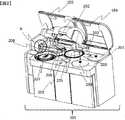
- FIG. 1is an overall view of the exterior of the apparatus with the protective cover closed in one embodiment of the present invention.
- the apparatus cover of the automatic analyzer 101includes a central protective cover 102, left and right upper covers (sample disk side) 103, and upper cover (reagent disk side) 104, and there is a risk of infection of the sample dispensing mechanism 206 and the like.
- An objectis covered with a protective cover 102 and protected by an interlock mechanism 208.
- the interlock mechanism 208is configured such that when the protective cover 102 is opened, the power is turned off.
- the central protective cover 102, the left and right upper covers (sample disk side) 103, and the upper cover (reagent disk side) 104can be independently controlled to open and close.
- FIG. 2is a diagram showing an external appearance of the automatic analyzer according to the present embodiment in a state where the upper cover and the protective cover are opened.
- the upper cover (sample disk side) 103 and the upper cover (reagent disk side) 104are covers that can be opened and closed by a general user even during an analysis operation, and access the sample disk 207, the first reagent disk 201, and the second reagent disk 204. It can be opened and closed at all times to make it easier. Since the first reagent dispensing mechanism 202 and the second reagent dispensing mechanism 203 are considered to have a low risk of infection, puncture, and the like, they are arranged outside the protective cover 102 in this embodiment. You may arrange.
- the protective cover 102is a cover that should be set so that it can be opened and closed by a service person who performs maintenance work or a user who has undergone a certain course, such as a sample dispensing mechanism 206 that is considered to be at risk of infection, stinging, etc.
- the operation unit 403is protected.
- the protective cover 102is locked and cannot be opened by the protective cover lock mechanism 209 during the analysis so that the user does not carelessly open the protective cover 102 during the analysis operation to stop the analysis.
- FIG. 3Ais an enlarged view of the portion A in FIG. 2, and shows the appearance of the interlock mechanism 208, the interlock release mechanism 303, and the maintenance key 301.
- FIG. 3 (a)the protective cover 102 is depicted by being cut in cross section in order to easily show the arrangement of the interlock mechanism 208.
- the interlock mechanism 208mainly includes an interlock switch mechanism 302, an interlock release mechanism 303, and a maintenance key 301.
- the maintenance key 301is removable. When the maintenance key 301 is inserted into the interlock release mechanism 208, the function of the interlock mechanism 208 that releases the power when the protective cover 102 is opened is released.
- the maintenance key 301when the maintenance key 301 is inserted into the interlock release mechanism 208, power is supplied to the operating unit 403 regardless of whether the protective cover 102 is opened or closed.
- the maintenance key 301is activated simply by inserting the maintenance key 301 into the interlock release mechanism 208, and the power supply is shut off.
- An embodiment that is effective by rotatingcan also be considered.
- the protective cover 102 and the maintenance key 301physically interfere with each other, and the protective cover 102 cannot be completely closed.
- the user or servicemancan recognize that the function of the interlock mechanism 208 has been released.
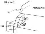
- FIG. 3 (b)is a diagram schematically depicting FIG. 3 (a).
- the interlock switch mechanism 302is a switch mechanism that physically cuts off the power.
- FIG. 4is a schematic diagram showing a circuit of the interlock mechanism 208 in the automatic analyzer according to the present embodiment.
- An operation unit 403 schematically showing a mechanism unit such as the sample dispensing mechanism 206has a structure in which power is supplied from the power supply unit 401 to operate.
- a relay 402is provided in a power supply line connecting the power supply unit 401 and the operation unit 403, and an interlock switch 404 and an interlock release switch 405 that can physically cut off the power supply are connected to the relay 402. .
- the interlock switch 404is a switch in which a circuit is assembled so that the interlock switch mechanism 302 is turned on when the interlock switch mechanism 302 is physically pressed and power is sent from the power supply unit 401 to the operation unit 403 via the relay 402.
- the interlock release switch 405is turned on when the maintenance key 301 is inserted in the interlock release mechanism 303, and a circuit is configured so that power is sent from the power supply unit 401 to the operation unit 403 via the relay 402. Switch.
- the control unit 406that controls the operation of the operation unit 403 controls the operation unit 403 based on the opening / closing information from the protection cover opening / closing detector 407 that detects the opening / closing of the protection cover 102 and the operation information from the interlock release switch 405. Control.
- FIG. 5Ashows an example of the arrangement of the interlock mechanism 208 in the automatic analyzer according to the present embodiment, and is a schematic diagram when the maintenance key 301 is inserted into the interlock release switch 405.
- the interlock switch lever 501cannot push the interlock switch mechanism 302. Therefore, power is not supplied to the operation unit 403, and the operation unit 403 cannot be operated, thereby ensuring safety for general users. Is done.
- maintenancethat requires the operation of the operating unit 403, for example, position adjustment or position confirmation of the sample probe of the sample dispensing mechanism 206 cannot be performed.
- the protective cover 102is opened. Power is supplied to the unit 403, and maintenance that requires operation of the operating unit 403 can be performed.
- the opening / closing of the protective cover 102is confirmed by the protective cover opening / closing detection sensor 503.
- the open / close detection plate 502is detached from the protective cover open / close detector 407, so that the control unit 406 recognizes that the protective cover 102 is open, and the automatic analyzer 101 does not shift to the analysis operation.
- the control unit 406instructs the automatic analyzer 101 to issue an alarm or the like. Even when the control unit 406 recognizes that the open / close detection plate 502 is not inserted into the protective cover open / close detector 407 and the protective cover 102 is open, a service person or a user who has received a certain class has
- the operation unit 403is configured to perform a maintenance operation. For this instruction, the control unit 406 obtains the opening / closing information of the protective cover opening / closing detector 407, and controls the operation of the operation unit 403 based on the information.
- the operation unit 403may operate in an unexpected scene due to forgetting to pull out the maintenance key 301 and the safety of general users cannot be ensured.
- the maintenance key insertion portis located at a position that does not interfere with the opening / closing operation of the protective cover, such as the front surface of the apparatus.
- the protective cover 102when the maintenance key 301 is inserted into the interlock release mechanism 303, the protective cover 102 cannot be closed because it physically interferes with the maintenance key 301, so that it is visually prevented from being forgotten. can do.
- the protective cover open / close detector 407detects that the protective cover 102 is not closed, and the control unit 406 generates an alarm. By doing so, the analysis operation, which is the main business of general users, cannot be performed, so that forgetting to remove the maintenance key 301 is prevented and the operation unit 403 is not operated, thereby ensuring the safety of general users.
- the operation of the interlock release mechanism 303is performed by the maintenance key 301.
- an inverted switch, a screw-in switch, or the likecan be applied as the operating member.
- FIG. 5Bshows an example of the arrangement of the interlock mechanism 208 and the interlock release mechanism 303 in the automatic analyzer according to the present embodiment, where the maintenance key 301 is not inserted into the interlock release switch 405.
- the protective cover 102can be closed, the interlock switch 501 is pushed by the interlock switch mechanism 301, the interlock switch 404 is turned on, and power is supplied to the operation unit 403.
- the control unit 406recognizes that the open / close detection plate 502 is inserted into the protective cover open / close detector 407 and the protective cover 102 is closed, and the operation unit 403 can perform normal operation.
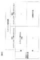
- FIG. 6shows operation control of the operation unit 403 by the relationship between the interlock release mechanism and the protective cover opening / closing detector.
- the operation unit 403is controlled by the control unit 406.
- the interlock release mechanism 303is enabled (interlock mechanism 208 is disabled), and the protective cover open / close detector 407 detects the open state, Maintenance work that a user who has received a certain class needs to perform with the protective cover 102 opened can be performed. At this time, an alarm is displayed on the display screen of the automatic analyzer 101, and the analysis operation is controlled.
- the interlock release mechanism 303When the maintenance key is not inserted into the interlock release mechanism 303, the interlock release mechanism 303 is disabled (the interlock mechanism 208 is enabled), and the protective cover open / close detector 407 detects the closed state, a general user Can perform analysis operations. At this time, a display indicating that analysis is possible may be displayed on the display screen of the automatic analyzer 101.
- the protective cover 102interferes with the maintenance key 301, so that the protective cover open / close detector 407 does not detect the closed state.
Landscapes
- Physics & Mathematics (AREA)
- Health & Medical Sciences (AREA)
- Life Sciences & Earth Sciences (AREA)
- Chemical & Material Sciences (AREA)
- Analytical Chemistry (AREA)
- Biochemistry (AREA)
- General Health & Medical Sciences (AREA)
- General Physics & Mathematics (AREA)
- Immunology (AREA)
- Pathology (AREA)
- Automatic Analysis And Handling Materials Therefor (AREA)
Abstract
Description
Translated fromJapanese本発明は、血液や尿などのサンプルに含まれる成分量を分析する自動分析装置に関し、特に装置カバーの開閉制御を行うインターロック機構に関する。The present invention relates to an automatic analyzer that analyzes the amount of a component contained in a sample such as blood or urine, and more particularly to an interlock mechanism that controls opening and closing of a device cover.
血液等の検体を分析する自動分析装置において、分析動作中やメンテナンス作業中に一般のユーザーが誤って危険部位を含む機構部に接触しない様に、カバーの開閉制御を行うインターロック機構の設置が有効である。インターロック機構は、危険部位を含む機構部を覆う保護カバーが閉じた状態でのみ機構部を動作可能とする安全機構である。しかし、分注プローブの位置調整/確認など一部のメンテナンス作業には、目視確認や内部清掃のために保護カバーを開いた状態のまま機構部を動作させる必要があるものが存在する。そのため、インターロック機構には、保護カバーを閉じた状態でのみ機構部を動作させる機能に加え、保護カバーを開いた状態でも一部の機構部を動作させ、特定のメンテナンス作業を可能とする機能が必要となる場合がある。In automatic analyzers that analyze specimens such as blood, an interlock mechanism that controls the opening and closing of the cover is installed so that ordinary users do not accidentally come into contact with mechanisms that contain dangerous parts during analysis operations or maintenance operations. It is valid. The interlock mechanism is a safety mechanism that allows the mechanism to operate only when the protective cover that covers the mechanism including the dangerous part is closed. However, in some maintenance operations such as position adjustment / confirmation of the dispensing probe, there are those that require the mechanism to be operated with the protective cover open for visual confirmation and internal cleaning. Therefore, in addition to the function to operate the mechanism part only when the protective cover is closed, the interlock mechanism has a function that allows a part of the mechanism part to operate even when the protective cover is opened to perform specific maintenance work. May be required.
特許文献WO2013/035471には、検体を搬送する搬送機構と、前記検体を分析する分析部とを備え、搬送機構を含む可動機構を覆う保護カバーを有する自動分析装置において、保護カバーを開けた場合に可動機構の動作を停止させるインターロック機構と、そのインターロック機構の一部または全てを無効にするインターロック解除機構とを備える自動分析装置が開示されている。Patent Document WO2013 / 035471 includes an automatic analyzer that includes a transport mechanism that transports a specimen and an analysis unit that analyzes the specimen, and has a protective cover that covers a movable mechanism including the transport mechanism. An automatic analyzer including an interlock mechanism that stops the operation of the movable mechanism and an interlock release mechanism that disables part or all of the interlock mechanism is disclosed.
インターロック機構の開閉操作や、一部のメンテナンス作業中にインターロック機構を解除させた状態で機構部を動作させる作業ができるのは、メンテナンス作業を行うサービスマンや、一定の講習を受けたユーザーに限られており、一般のユーザーはインターロックの開閉操作やインターロック機構を解除させた状態で装置の作業を行うことは安全上好ましくない。そのため、インターロック機構を解除させるインターロック解除機構の作動部材(メンテナンスキー)は装置管理者が厳重に保管している。Opening / closing operation of the interlock mechanism and operation of the mechanism part with the interlock mechanism being released during some maintenance work can be performed by service personnel who perform maintenance work and users who have received a certain class For general users, it is not preferable in terms of safety to operate the apparatus in a state where the interlock opening / closing operation or the interlock mechanism is released. Therefore, the operating member (maintenance key) of the interlock release mechanism that releases the interlock mechanism is strictly stored by the device manager.
しかし、メンテナンス作業中、インターロック解除機構にメンテナンスキーを挿入したまま一時的にサービスマンなどが席を外した際に、一般のユーザーはインターロックが解除されていることに気付かず装置に触れてしまう可能性がある。However, during maintenance work, when a service person temporarily removes the seat with the maintenance key inserted in the interlock release mechanism, the general user does not notice that the interlock is released and touches the device. There is a possibility.
特許文献WO2013/035471に開示された自動分析装置は、保護カバーが開いた場合には、分析装置上の可動機構への電源供給を遮断し動作しないようにするインターロック機構を備えたものである。さらに、保護カバーが開いた状態でインターロック解除機構にメンテナンスキー等を挿入し、メンテナンスモードに移行することにより、可動機構への電源供給を行い、特定のメンテナンス作業のみを実行可能とする。The automatic analyzer disclosed in Patent Document WO2013 / 035471 is provided with an interlock mechanism that shuts off the power supply to the movable mechanism on the analyzer so as not to operate when the protective cover is opened. . Further, by inserting a maintenance key or the like into the interlock release mechanism with the protective cover open, and shifting to the maintenance mode, power is supplied to the movable mechanism, and only specific maintenance work can be executed.
しかし、このような自動分析装置のメンテナンス作業中、サービスマンが保護カバーを閉めていたとしても、インターロック解除機構にメンテナンスキーを挿入したまま一時的にサービスマンなどが席を外した場合は、一般のユーザーはインターロックが解除されていることに気付かず保護カバーを開けることが可能となってしまい、さらに当該保護カバーを開けた状態で特定のメンテナンス作業動作中の装置に触れてしまう可能性がある。However, even if the serviceman closes the protective cover during maintenance work of such an automatic analyzer, if the serviceman temporarily leaves the seat with the maintenance key inserted in the interlock release mechanism, A general user may be able to open the protective cover without noticing that the interlock has been released, and may also touch the device during certain maintenance operations while the protective cover is open. There is.
本発明は、メンテナンス作業を行うサービスマンや、一定の講習を受けたユーザーが確実にインターロックを無効から有効への切替えることを可能とし、安全性をより向上させたインターロック機構を備えた自動分析装置を提供することを目的とする。The present invention makes it possible for a service person who performs maintenance work or a user who has received a certain training to reliably switch the interlock from invalid to valid, and is equipped with an automatic interlock mechanism that further improves safety. An object is to provide an analyzer.
本発明の自動分析装置は、検体の分析に必要な動作を実施するための動作部と、前記動作部の動作を制御する制御部と、動作部を覆う保護カバーと、保護カバーの開閉状態を検知する保護カバー開閉検出器と、保護カバーを開けた場合に可動機構の動作を停止させるインターロック機構と、インターロック機構の一部またはすべてを無効にするインターロック解除機構と、インターロック解除機構を作動させるための作動部材(メンテナンスキー)を備え、前記メンテナンスキーが前記インターロック解除機構に挿入された状態のとき、前記保護カバーと前記メンテナンスキーが物理的に干渉し、前記保護カバーを閉じることができない構成であることを特徴とする。An automatic analyzer according to the present invention includes an operation unit for performing an operation necessary for analyzing a sample, a control unit for controlling the operation of the operation unit, a protective cover for covering the operation unit, and an open / closed state of the protective cover. Protective cover open / close detector to detect, interlock mechanism to stop operation of movable mechanism when protective cover is opened, interlock release mechanism to disable part or all of interlock mechanism, and interlock release mechanism When the maintenance key is inserted into the interlock release mechanism, the protective cover and the maintenance key physically interfere to close the protective cover. It is the structure which cannot do.
本発明によって、メンテナンス作業を行うサービスマンや、一定の講習を受けたユーザーが確実にインターロック機構を無効から有効への切替えることを可能とすることができる。According to the present invention, it is possible for a service person who performs maintenance work or a user who has received a certain training to reliably switch the interlock mechanism from invalid to valid.
一般のユーザーはインターロックが解除されていることに視覚的に気付くことが可能となる。これによって、一般のユーザーはインターロックが解除されており、分析動作ができない状態であることを認識することが可能となる。General users can visually notice that the interlock has been released. As a result, a general user can recognize that the interlock is released and the analysis operation cannot be performed.
以下、本発明の実施の形態を図面に基づいて詳細に説明する。なお、本実施の形態を説明するための全図において同一機能を有するものは原則として同一の符号を付している。Hereinafter, embodiments of the present invention will be described in detail with reference to the drawings. Note that components having the same function are denoted by the same reference symbols throughout the drawings for describing the embodiment.
図1は、本発明の一実施例における保護カバーを閉じた状態の装置外装の全体図である。自動分析装置101の装置カバーは、中央の保護カバー102と、左右の上部カバー(サンプルディスク側)103および上部カバー(試薬ディスク側)104からなり、サンプル分注機構206等の感染の危険があるものは、保護カバー102で覆われ、インターロック機構208により保護される構成となっている。なお、インターロック機構208とは保護カバー102を開けると、電源が切断される構成である。中央の保護カバー102と、左右の上部カバー(サンプルディスク側)103および上部カバー(試薬ディスク側)104は各々独立して開閉制御が可能な構成となっている。FIG. 1 is an overall view of the exterior of the apparatus with the protective cover closed in one embodiment of the present invention. The apparatus cover of the
図2は、本実施の形態に係る自動分析装置において、上部カバーおよび保護カバーを開いた状態の外観を示す図である。上部カバー(サンプルディスク側)103および上部カバー(試薬ディスク側)104は、一般のユーザーが分析動作中でも開閉可能なカバーであり、サンプルディスク207や第一試薬ディスク201、第二試薬ディスク204にアクセスしやすくするため、常時開閉可能となっている。第一試薬分注機構202、第二試薬分注機構203は感染や刺傷等のリスクが低いと考えられるため、本実施例では保護カバー102の外側に配置されているが、保護カバー102内に配置してもよい。保護カバー102は、メンテナンス作業を行うサービスマンや、一定の講習を受けたユーザーが開閉制御できるように設定するべきカバーであり、感染や刺傷等のリスクがあると考えられるサンプル分注機構206等の動作部403を保護している。また、分析動作中にユーザーが不用意に、保護カバー102を開けて分析が停止しないように、分析中は保護カバーロック機構209により保護カバー102はロックされ開けられない構造となっている。FIG. 2 is a diagram showing an external appearance of the automatic analyzer according to the present embodiment in a state where the upper cover and the protective cover are opened. The upper cover (sample disk side) 103 and the upper cover (reagent disk side) 104 are covers that can be opened and closed by a general user even during an analysis operation, and access the
図3(a)は、図2のA部位の拡大図で、インターロック機構208、インターロック解除機構303、メンテナンスキー301の外観を示す図である。図3(a)において、インターロック機構208の配置を分かりやすく示すために、保護カバー102は断面でカットされた描写となっている。インターロック機構208は、主にインターロックスイッチ機構302、インターロック解除機構303、メンテナンスキー301から構成されており、メンテナンスキー301は、取り外し可能となっている。インターロック解除機構208にメンテナンスキー301が挿入されると、保護カバー102を開けると電源が遮断されるというインターロック機構208の機能が解除される。そのため、インターロック解除機構208にメンテナンスキー301が挿入されると、保護カバー102の開閉にかかわらず、動作部403に電源が供給される。本実施例では簡単のため、インターロック解除機構208にメンテナンスキー301を挿入するだけで有効となり電源が遮断されるが、メンテナンスキー301を挿入しただけでは電源が遮断されず有効側にメンテナンスキー301を回転させることで有効となる実施例も考えられる。本図からも分かるように、メンテナンスキー301がインターロック解除機構303に挿入された状態では、保護カバー102とメンテナンスキー301が物理的に干渉し、保護カバー102を完全に閉じることができない構造となっており、ユーザーやサービスマンにインターロック機構208の機能が解除された危険な状態であることを認識させることができる。FIG. 3A is an enlarged view of the portion A in FIG. 2, and shows the appearance of the
図3(b)は、図3(a)を模式的に描写した図である。本図で示すように、インターロックスイッチ機構302は物理的に電源を切断するスイッチ機構となっている。FIG. 3 (b) is a diagram schematically depicting FIG. 3 (a). As shown in this figure, the
図4は、本実施の形態に係る自動分析装置において、インターロック機構208の回路を示す模式図である。サンプル分注機構206などの機構部を模式的に示す動作部403は、電源部401により電源供給され動作する構造となっている。電源部401と動作部403をつなぐ電源ライン中にリレー402が設けられており、リレー402には物理的に電源を切断することができるインターロックスイッチ404およびインターロック解除スイッチ405が接続されている。インターロックスイッチ404は、インターロックスイッチ機構302が物理的に押されるとONになり、リレー402を介して電源部401から動作部403に電源が送られるように回路が組まれるスイッチである。また、インターロック解除スイッチ405は、インターロック解除機構303にメンテナンスキー301が挿入されている場合ONになり、リレー402を介して電源部401から動作部403に電源が送られるように回路が組まれるスイッチである。また、動作部403の動作を制御している制御部406は、保護カバー102の開閉を検知する保護カバー開閉検知器407からの開閉情報やインターロック解除スイッチ405から作動情報に基づき動作部403を制御する。FIG. 4 is a schematic diagram showing a circuit of the
図5(a)は、本実施の形態に係る自動分析装置において、インターロック機構208の配置の一例を示し、メンテナンスキー301がインターロック解除スイッチ405に挿入されている場合の模式図である。保護カバー102が開いた状態では、インターロックスイッチレバー501がインターロックスイッチ機構302を押すことができないため、動作部403に電源供給されず、動作部403が動作できなくなり、一般ユーザーの安全が確保される。しかしながら、動作部403の動作が必要なメンテナンス、例えばサンプル分注機構206のサンプルプローブの位置調整や位置確認等を実施することができない。FIG. 5A shows an example of the arrangement of the
サービスマンや一定の講習を受けたユーザーが、インターロック解除機構303にメンテナンスキー301を挿入し、メンテナンスキー301にてインターロック解除スイッチ405を有効に切り替えることで保護カバー102が開いた状態でも動作部403に電源供給され、動作部403の動作が必要なメンテナンスを実施することができるようになる。保護カバー102の開閉は、保護カバー開閉検知センサ503によって確認される。保護カバー102が開いた状態では、開閉検知版502が保護カバー開閉検知器407から外れるため、保護カバー102が開いている事が制御部406により認識され、自動分析装置101が分析動作に移行しないように制御部406により制御され、自動分析装置101にアラーム等の発信を指示する。なお、保護カバー開閉検知器407に開閉検知板502が挿入されず保護カバー102が開いていると制御部406が認識している場合であっても、サービスマンや一定の講習を受けたユーザーが、インターロック解除機構303にメンテナンスキー301を挿入し、メンテナンスキー301にてインターロック解除スイッチ405を有効に切り替えられていると、動作部403はメンテナンス動作できるように構成されている。なお、この指示は制御部406が保護カバー開閉検知器407の開閉情報を入手し、その情報をもとに、動作部403の動作を制御している。Even if a service person or a user who has received a certain class of training inserts the
従来技術においては、メンテナンスキー301の抜き忘れ等により、動作部403が予想外の場面で動作し一般ユーザーの安全が確保できない可能性も考えられた。たとえば、メンテナンスキーの差込口が装置の前面など、保護カバーの開閉動作に干渉しない位置にある場合などがあった。本実施例の構成においては、メンテナンスキー301がインターロック解除機構303に挿入された状態では、メンテナンスキー301と物理的に干渉し保護カバー102を閉じることができないため、視覚的に抜き忘れを防止することができる。また、保護カバー開閉検知器407は保護カバー102が閉じていないことを検知し、制御部406がアラームを発生させる。そうすることで、一般ユーザーのメイン業務である分析動作を実施することができないため、メンテナンスキー301の抜き忘れを防止するとともに、動作部403が動作させないことにより一般ユーザーの安全確保にもつながる。In the prior art, there is a possibility that the
本実施例では、インターロック解除機構303の作動をメンテナンスキー301により行う構成であるが、インターロック解除機構303を作動させた状態で、保護カバー102と物理的に干渉する構成であればどのような構成でも適用可能である。例えば、作動部材として、倒立型スイッチやねじ込み式スイッチなども適用可能である。In this embodiment, the operation of the
図5(b)は本実施の形態に係る自動分析装置において、インターロック機構208、インターロック解除機構303の配置の一例を示し、メンテナンスキー301がインターロック解除スイッチ405に挿入されていない場合の模式図である。メンテナンスキー301が挿入されていない場合、保護カバー102は閉じることができ、インターロックスイッチ501がインターロックスイッチ機構301を押されてインターロックスイッチ404がONされ動作部403に電源が供給される。また、保護カバー開閉検知器407に開閉検知板502が挿入され保護カバー102が閉じていることを制御部406が認識し、動作部403は通常動作が可能となる。FIG. 5B shows an example of the arrangement of the
図6はインターロック解除機構と保護カバー開閉検知器との関係による動作部403の動作制御を示している。この動作部403の制御は制御部406によって制御されている。インターロック解除機構303にメンテナンスキー301が挿入され、インターロック解除機構303が有効(インターロック機構208は無効)となり、保護カバー開閉検知器407が開状態を検知している場合は、サービスマンや一定の講習を受けたユーザーが保護カバー102をあけた状態で実施する必要があるメンテナンス作業ができる。この際は自動分析装置101の表示画面にアラーム表示され分析動作はできないように制御されている。インターロック解除機構303にメンテナンスキーが挿入されず、インターロック解除機構303が無効(インターロック機構208は有効)となり、保護カバー開閉検知器407が閉状態を検知している場合は、一般のユーザーが分析動作を行うことができる。この際は自動分析装置101の表示画面に分析可能という表示がされてもよい。FIG. 6 shows operation control of the
なお、インターロック解除機構303にメンテナンスキー301が挿入されている場合は、保護カバー102がメンテナンスキー301に干渉するため、保護カバー開閉検知器407が閉状態を検知することはない。When the
101自動分析装置
102保護カバー
103上部カバー(サンプルディスク側)
104上部カバー(試薬ディスク側)
201第一試薬ディスク
202第一試薬分注機構
203第二試薬分注機構
204第二試薬ディスク
205反応ディスク
206サンプル分注機構
207サンプルディスク
208インターロック機構
209保護カバーロック機構
301メンテナンスキー
302インターロックスイッチ機構
303インターロック解除機構
401電源部
402リレー
403動作部
404インターロックスイッチ
405インターロック解除スイッチ
406制御部
407保護カバー開閉検知器
501インターロックスイッチレバー
502開閉検知板101
104 Top cover (reagent disc side)
201
Claims (5)
Translated fromJapaneseインターロック解除機構と、インターロック解除機構を作動させるための作動部材を備え、前記作動部材が前記インターロック解除機構を作動させた状態の場合に、前記保護カバーと前記作動部材が物理的に干渉することを特徴とする自動分析装置。An operation unit for performing an operation necessary for analyzing the sample, a control unit for controlling the operation of the operation unit, a protective cover for covering the operation unit, and an operation of the movable mechanism when the protective cover is opened. An interlock mechanism for stopping, an interlock release mechanism for disabling part or all of the interlock mechanism, and an operating member for operating the interlock release mechanism, the operating member operating the interlock release mechanism An automatic analyzer characterized in that the protective cover and the actuating member physically interfere with each other in the state in which the protective cover is brought into contact.
前記保護カバーの開閉状態を検知する保護カバー開閉検知器を備え、前記保護カバー開閉検知器の情報に基づき、前記制御部が前記動作部を制御することを特徴とする自動分析装置。The automatic analyzer according to claim 1,
An automatic analyzer comprising a protective cover open / close detector for detecting an open / closed state of the protective cover, wherein the control unit controls the operating unit based on information of the protective cover open / close detector.
前記インターロック解除機構は、前記作動部材によりインターロック解除機能の有効/無効を切り替えることができ、前記制御部はインターロック解除機能の有効/無効に応じて、前記動作部を制御することを特徴とする自動分析装置。The automatic analyzer according to claim 1,
The interlock release mechanism can switch enable / disable of the interlock release function by the operating member, and the control unit controls the operation unit according to the enable / disable of the interlock release function. An automatic analyzer.
前記制御部は前記保護カバー開閉検知器の情報と前期インターロック解除機能の有効/無効情報の組合せに応じて、前記動作部の制御およびアラームの選択/発信を行うことを特徴とする自動分析装置。In the automatic analyzer according to claim 2 or claim 3,
The control unit controls the operation unit and selects / transmits an alarm according to a combination of information on the protective cover opening / closing detector and validity / invalidity information of the previous interlock release function. .
前記制御部は、前記保護カバーの開閉状態を検知する保護カバー開閉検知器が開状態を認識した場合は、前記動作部に分析動作をさせないように制御することを特徴とする自動分析装置。The automatic analyzer according to claim 2,
The automatic analysis apparatus, wherein the control unit controls the operation unit not to perform an analysis operation when a protection cover open / close detector that detects the open / close state of the protective cover recognizes the open state.
Priority Applications (1)
| Application Number | Priority Date | Filing Date | Title |
|---|---|---|---|
| CN201890000907.XUCN211785582U (en) | 2017-06-16 | 2018-05-09 | Automatic analyzer |
Applications Claiming Priority (2)
| Application Number | Priority Date | Filing Date | Title |
|---|---|---|---|
| JP2017-118239 | 2017-06-16 | ||
| JP2017118239 | 2017-06-16 |
Publications (1)
| Publication Number | Publication Date |
|---|---|
| WO2018230198A1true WO2018230198A1 (en) | 2018-12-20 |
Family
ID=64660840
Family Applications (1)
| Application Number | Title | Priority Date | Filing Date |
|---|---|---|---|
| PCT/JP2018/017878CeasedWO2018230198A1 (en) | 2017-06-16 | 2018-05-09 | Automated analysis device |
Country Status (2)
| Country | Link |
|---|---|
| CN (1) | CN211785582U (en) |
| WO (1) | WO2018230198A1 (en) |
Cited By (5)
| Publication number | Priority date | Publication date | Assignee | Title |
|---|---|---|---|---|
| JPWO2021235015A1 (en)* | 2020-05-22 | 2021-11-25 | ||
| WO2022009455A1 (en)* | 2020-07-09 | 2022-01-13 | 株式会社日立ハイテク | Automated analyzer |
| US20220178955A1 (en)* | 2019-04-11 | 2022-06-09 | Hitachi High-Tech Corporation | Automatic analyzer |
| US20220206022A1 (en)* | 2019-04-11 | 2022-06-30 | Hitachi High-Tech Corporation | Interlock unit and automated analyzer equipped with same |
| EP4379386A1 (en) | 2022-11-29 | 2024-06-05 | Roche Diagnostics GmbH | Method for operating an in-vitro-diagnostics laboratory system and in-vitro-diagnostics laboratory system |
Families Citing this family (1)
| Publication number | Priority date | Publication date | Assignee | Title |
|---|---|---|---|---|
| CN113074758A (en)* | 2021-03-22 | 2021-07-06 | 苏州大学 | Electric equipment, and operation control method and device of electric equipment |
Citations (5)
| Publication number | Priority date | Publication date | Assignee | Title |
|---|---|---|---|---|
| JPS62252690A (en)* | 1986-04-25 | 1987-11-04 | Nec Corp | Safety device for laser beam machine |
| JPH0547271A (en)* | 1991-08-16 | 1993-02-26 | Fuji Photo Film Co Ltd | Interlock actuator |
| US20090180931A1 (en)* | 2007-09-17 | 2009-07-16 | Sequenom, Inc. | Integrated robotic sample transfer device |
| JP2009190103A (en)* | 2008-02-13 | 2009-08-27 | Hitachi High-Tech Control Systems Corp | Semiconductor transfer device |
| WO2013035471A1 (en)* | 2011-09-09 | 2013-03-14 | 株式会社日立ハイテクノロジーズ | Automated analyzer and maintenance method for same |
- 2018
- 2018-05-09WOPCT/JP2018/017878patent/WO2018230198A1/ennot_activeCeased
- 2018-05-09CNCN201890000907.XUpatent/CN211785582U/enactiveActive
Patent Citations (5)
| Publication number | Priority date | Publication date | Assignee | Title |
|---|---|---|---|---|
| JPS62252690A (en)* | 1986-04-25 | 1987-11-04 | Nec Corp | Safety device for laser beam machine |
| JPH0547271A (en)* | 1991-08-16 | 1993-02-26 | Fuji Photo Film Co Ltd | Interlock actuator |
| US20090180931A1 (en)* | 2007-09-17 | 2009-07-16 | Sequenom, Inc. | Integrated robotic sample transfer device |
| JP2009190103A (en)* | 2008-02-13 | 2009-08-27 | Hitachi High-Tech Control Systems Corp | Semiconductor transfer device |
| WO2013035471A1 (en)* | 2011-09-09 | 2013-03-14 | 株式会社日立ハイテクノロジーズ | Automated analyzer and maintenance method for same |
Cited By (12)
| Publication number | Priority date | Publication date | Assignee | Title |
|---|---|---|---|---|
| US20220178955A1 (en)* | 2019-04-11 | 2022-06-09 | Hitachi High-Tech Corporation | Automatic analyzer |
| US20220206022A1 (en)* | 2019-04-11 | 2022-06-30 | Hitachi High-Tech Corporation | Interlock unit and automated analyzer equipped with same |
| EP3955005A4 (en)* | 2019-04-11 | 2022-12-21 | Hitachi High-Tech Corporation | AUTOMATIC ANALYSIS DEVICE |
| US12210025B2 (en)* | 2019-04-11 | 2025-01-28 | Hitachi High-Tech Corporation | Interlock unit and automated analyzer equipped with same |
| US12392788B2 (en)* | 2019-04-11 | 2025-08-19 | Hitachi High-Tech Corporation | Automatic analyzer |
| JPWO2021235015A1 (en)* | 2020-05-22 | 2021-11-25 | ||
| WO2021235015A1 (en)* | 2020-05-22 | 2021-11-25 | 株式会社日立ハイテク | Automatic analyzer and assembly assistance system thereof |
| JP7433426B2 (en) | 2020-05-22 | 2024-02-19 | 株式会社日立ハイテク | Automatic analyzer and its assembly support system |
| WO2022009455A1 (en)* | 2020-07-09 | 2022-01-13 | 株式会社日立ハイテク | Automated analyzer |
| EP4180819A4 (en)* | 2020-07-09 | 2024-07-03 | Hitachi High-Tech Corporation | AUTOMATED ANALYZER |
| EP4379386A1 (en) | 2022-11-29 | 2024-06-05 | Roche Diagnostics GmbH | Method for operating an in-vitro-diagnostics laboratory system and in-vitro-diagnostics laboratory system |
| WO2024115303A1 (en) | 2022-11-29 | 2024-06-06 | F. Hoffmann-La Roche Ag | Method for operating an in-vitro-diagnostics laboratory system and in-vitro-diagnostics laboratory system |
Also Published As
| Publication number | Publication date |
|---|---|
| CN211785582U (en) | 2020-10-27 |
Similar Documents
| Publication | Publication Date | Title |
|---|---|---|
| WO2018230198A1 (en) | Automated analysis device | |
| JP6309965B2 (en) | Protective door monitoring system | |
| JP5894168B2 (en) | Automatic analyzer and maintenance method thereof | |
| US20100055663A1 (en) | Method for controlling a tissue processor and tissue processor | |
| ES2627821T3 (en) | Emergency button, emergency button terminal, use of a display on an emergency button and procedure for operating an emergency button | |
| KR20150079695A (en) | Motor vehicle lock with position detection means | |
| DE602005011495D1 (en) | SECURITY LOCK FOR ELEVATOR BAY DOOR, THE ASST, AND SO EQUIPPED LIFT | |
| EP1921236A3 (en) | Safety Cabinet | |
| JP6066182B2 (en) | Laser equipment | |
| JP3711663B2 (en) | External circuit handle device for circuit breaker | |
| KR20090075271A (en) | Refrigerator and refrigerator door automatic opening and closing method with automatic retractable drawer door | |
| CN110940823A (en) | Automatic analysis device | |
| JP2001165393A (en) | Control panel with interlock mechanism | |
| CA3209403A1 (en) | Water tap and method for operating the water tap | |
| JP5063481B2 (en) | Malfunction prevention mechanism used in biological sample analyzer | |
| JP2009203774A (en) | Door device | |
| JP2002245884A (en) | Switch cover | |
| JP2009281004A (en) | Door device | |
| US20190249920A1 (en) | Grid voltage-operated refrigerating device | |
| JPH0326676A (en) | Operation control panel for elevator | |
| JP4915887B2 (en) | Operation box for gas fire extinguishing equipment | |
| JP2003185092A (en) | Safety device release mechanism | |
| JP4677347B2 (en) | Circuit breaker actuator | |
| JPH0263710A (en) | Purge shield of injection molding machine | |
| JP6576382B2 (en) | Elevator car operation panel |
Legal Events
| Date | Code | Title | Description |
|---|---|---|---|
| 121 | Ep: the epo has been informed by wipo that ep was designated in this application | Ref document number:18817741 Country of ref document:EP Kind code of ref document:A1 | |
| NENP | Non-entry into the national phase | Ref country code:DE | |
| 122 | Ep: pct application non-entry in european phase | Ref document number:18817741 Country of ref document:EP Kind code of ref document:A1 | |
| NENP | Non-entry into the national phase | Ref country code:JP |