WO2018225757A1 - Unmanned aerial vehicle, unmanned aerial vehicle system, and battery system - Google Patents
Unmanned aerial vehicle, unmanned aerial vehicle system, and battery systemDownload PDFInfo
- Publication number
- WO2018225757A1 WO2018225757A1PCT/JP2018/021643JP2018021643WWO2018225757A1WO 2018225757 A1WO2018225757 A1WO 2018225757A1JP 2018021643 WJP2018021643 WJP 2018021643WWO 2018225757 A1WO2018225757 A1WO 2018225757A1
- Authority
- WO
- WIPO (PCT)
- Prior art keywords
- power
- battery
- main body
- power transmission
- air vehicle
- Prior art date
- Legal status (The legal status is an assumption and is not a legal conclusion. Google has not performed a legal analysis and makes no representation as to the accuracy of the status listed.)
- Ceased
Links
Images


Classifications
- B—PERFORMING OPERATIONS; TRANSPORTING
- B60—VEHICLES IN GENERAL
- B60L—PROPULSION OF ELECTRICALLY-PROPELLED VEHICLES; SUPPLYING ELECTRIC POWER FOR AUXILIARY EQUIPMENT OF ELECTRICALLY-PROPELLED VEHICLES; ELECTRODYNAMIC BRAKE SYSTEMS FOR VEHICLES IN GENERAL; MAGNETIC SUSPENSION OR LEVITATION FOR VEHICLES; MONITORING OPERATING VARIABLES OF ELECTRICALLY-PROPELLED VEHICLES; ELECTRIC SAFETY DEVICES FOR ELECTRICALLY-PROPELLED VEHICLES
- B60L50/00—Electric propulsion with power supplied within the vehicle
- B60L50/50—Electric propulsion with power supplied within the vehicle using propulsion power supplied by batteries or fuel cells
- B60L50/60—Electric propulsion with power supplied within the vehicle using propulsion power supplied by batteries or fuel cells using power supplied by batteries
- B—PERFORMING OPERATIONS; TRANSPORTING
- B60—VEHICLES IN GENERAL
- B60L—PROPULSION OF ELECTRICALLY-PROPELLED VEHICLES; SUPPLYING ELECTRIC POWER FOR AUXILIARY EQUIPMENT OF ELECTRICALLY-PROPELLED VEHICLES; ELECTRODYNAMIC BRAKE SYSTEMS FOR VEHICLES IN GENERAL; MAGNETIC SUSPENSION OR LEVITATION FOR VEHICLES; MONITORING OPERATING VARIABLES OF ELECTRICALLY-PROPELLED VEHICLES; ELECTRIC SAFETY DEVICES FOR ELECTRICALLY-PROPELLED VEHICLES
- B60L53/00—Methods of charging batteries, specially adapted for electric vehicles; Charging stations or on-board charging equipment therefor; Exchange of energy storage elements in electric vehicles
- B60L53/10—Methods of charging batteries, specially adapted for electric vehicles; Charging stations or on-board charging equipment therefor; Exchange of energy storage elements in electric vehicles characterised by the energy transfer between the charging station and the vehicle
- B60L53/12—Inductive energy transfer
- B60L53/122—Circuits or methods for driving the primary coil, e.g. supplying electric power to the coil
- B—PERFORMING OPERATIONS; TRANSPORTING
- B60—VEHICLES IN GENERAL
- B60L—PROPULSION OF ELECTRICALLY-PROPELLED VEHICLES; SUPPLYING ELECTRIC POWER FOR AUXILIARY EQUIPMENT OF ELECTRICALLY-PROPELLED VEHICLES; ELECTRODYNAMIC BRAKE SYSTEMS FOR VEHICLES IN GENERAL; MAGNETIC SUSPENSION OR LEVITATION FOR VEHICLES; MONITORING OPERATING VARIABLES OF ELECTRICALLY-PROPELLED VEHICLES; ELECTRIC SAFETY DEVICES FOR ELECTRICALLY-PROPELLED VEHICLES
- B60L53/00—Methods of charging batteries, specially adapted for electric vehicles; Charging stations or on-board charging equipment therefor; Exchange of energy storage elements in electric vehicles
- B60L53/10—Methods of charging batteries, specially adapted for electric vehicles; Charging stations or on-board charging equipment therefor; Exchange of energy storage elements in electric vehicles characterised by the energy transfer between the charging station and the vehicle
- B60L53/12—Inductive energy transfer
- B60L53/126—Methods for pairing a vehicle and a charging station, e.g. establishing a one-to-one relation between a wireless power transmitter and a wireless power receiver
- B—PERFORMING OPERATIONS; TRANSPORTING
- B60—VEHICLES IN GENERAL
- B60L—PROPULSION OF ELECTRICALLY-PROPELLED VEHICLES; SUPPLYING ELECTRIC POWER FOR AUXILIARY EQUIPMENT OF ELECTRICALLY-PROPELLED VEHICLES; ELECTRODYNAMIC BRAKE SYSTEMS FOR VEHICLES IN GENERAL; MAGNETIC SUSPENSION OR LEVITATION FOR VEHICLES; MONITORING OPERATING VARIABLES OF ELECTRICALLY-PROPELLED VEHICLES; ELECTRIC SAFETY DEVICES FOR ELECTRICALLY-PROPELLED VEHICLES
- B60L53/00—Methods of charging batteries, specially adapted for electric vehicles; Charging stations or on-board charging equipment therefor; Exchange of energy storage elements in electric vehicles
- B60L53/30—Constructional details of charging stations
- B60L53/35—Means for automatic or assisted adjustment of the relative position of charging devices and vehicles
- B60L53/36—Means for automatic or assisted adjustment of the relative position of charging devices and vehicles by positioning the vehicle
- B—PERFORMING OPERATIONS; TRANSPORTING
- B60—VEHICLES IN GENERAL
- B60L—PROPULSION OF ELECTRICALLY-PROPELLED VEHICLES; SUPPLYING ELECTRIC POWER FOR AUXILIARY EQUIPMENT OF ELECTRICALLY-PROPELLED VEHICLES; ELECTRODYNAMIC BRAKE SYSTEMS FOR VEHICLES IN GENERAL; MAGNETIC SUSPENSION OR LEVITATION FOR VEHICLES; MONITORING OPERATING VARIABLES OF ELECTRICALLY-PROPELLED VEHICLES; ELECTRIC SAFETY DEVICES FOR ELECTRICALLY-PROPELLED VEHICLES
- B60L53/00—Methods of charging batteries, specially adapted for electric vehicles; Charging stations or on-board charging equipment therefor; Exchange of energy storage elements in electric vehicles
- B60L53/30—Constructional details of charging stations
- B60L53/35—Means for automatic or assisted adjustment of the relative position of charging devices and vehicles
- B60L53/37—Means for automatic or assisted adjustment of the relative position of charging devices and vehicles using optical position determination, e.g. using cameras
- B—PERFORMING OPERATIONS; TRANSPORTING
- B60—VEHICLES IN GENERAL
- B60L—PROPULSION OF ELECTRICALLY-PROPELLED VEHICLES; SUPPLYING ELECTRIC POWER FOR AUXILIARY EQUIPMENT OF ELECTRICALLY-PROPELLED VEHICLES; ELECTRODYNAMIC BRAKE SYSTEMS FOR VEHICLES IN GENERAL; MAGNETIC SUSPENSION OR LEVITATION FOR VEHICLES; MONITORING OPERATING VARIABLES OF ELECTRICALLY-PROPELLED VEHICLES; ELECTRIC SAFETY DEVICES FOR ELECTRICALLY-PROPELLED VEHICLES
- B60L58/00—Methods or circuit arrangements for monitoring or controlling batteries or fuel cells, specially adapted for electric vehicles
- B60L58/10—Methods or circuit arrangements for monitoring or controlling batteries or fuel cells, specially adapted for electric vehicles for monitoring or controlling batteries
- B60L58/12—Methods or circuit arrangements for monitoring or controlling batteries or fuel cells, specially adapted for electric vehicles for monitoring or controlling batteries responding to state of charge [SoC]
- B—PERFORMING OPERATIONS; TRANSPORTING
- B64—AIRCRAFT; AVIATION; COSMONAUTICS
- B64C—AEROPLANES; HELICOPTERS
- B64C25/00—Alighting gear
- B64C25/02—Undercarriages
- B64C25/06—Undercarriages fixed
- B—PERFORMING OPERATIONS; TRANSPORTING
- B64—AIRCRAFT; AVIATION; COSMONAUTICS
- B64F—GROUND OR AIRCRAFT-CARRIER-DECK INSTALLATIONS SPECIALLY ADAPTED FOR USE IN CONNECTION WITH AIRCRAFT; DESIGNING, MANUFACTURING, ASSEMBLING, CLEANING, MAINTAINING OR REPAIRING AIRCRAFT, NOT OTHERWISE PROVIDED FOR; HANDLING, TRANSPORTING, TESTING OR INSPECTING AIRCRAFT COMPONENTS, NOT OTHERWISE PROVIDED FOR
- B64F1/00—Ground or aircraft-carrier-deck installations
- B64F1/22—Ground or aircraft-carrier-deck installations for handling aircraft
- B—PERFORMING OPERATIONS; TRANSPORTING
- B64—AIRCRAFT; AVIATION; COSMONAUTICS
- B64F—GROUND OR AIRCRAFT-CARRIER-DECK INSTALLATIONS SPECIALLY ADAPTED FOR USE IN CONNECTION WITH AIRCRAFT; DESIGNING, MANUFACTURING, ASSEMBLING, CLEANING, MAINTAINING OR REPAIRING AIRCRAFT, NOT OTHERWISE PROVIDED FOR; HANDLING, TRANSPORTING, TESTING OR INSPECTING AIRCRAFT COMPONENTS, NOT OTHERWISE PROVIDED FOR
- B64F1/00—Ground or aircraft-carrier-deck installations
- B64F1/36—Other airport installations
- B64F1/362—Installations for supplying conditioned air to parked aircraft
- B—PERFORMING OPERATIONS; TRANSPORTING
- B64—AIRCRAFT; AVIATION; COSMONAUTICS
- B64U—UNMANNED AERIAL VEHICLES [UAV]; EQUIPMENT THEREFOR
- B64U50/00—Propulsion; Power supply
- B64U50/10—Propulsion
- B64U50/19—Propulsion using electrically powered motors
- B—PERFORMING OPERATIONS; TRANSPORTING
- B64—AIRCRAFT; AVIATION; COSMONAUTICS
- B64U—UNMANNED AERIAL VEHICLES [UAV]; EQUIPMENT THEREFOR
- B64U50/00—Propulsion; Power supply
- B64U50/30—Supply or distribution of electrical power
- B64U50/37—Charging when not in flight
- B64U50/38—Charging when not in flight by wireless transmission
- H—ELECTRICITY
- H01—ELECTRIC ELEMENTS
- H01F—MAGNETS; INDUCTANCES; TRANSFORMERS; SELECTION OF MATERIALS FOR THEIR MAGNETIC PROPERTIES
- H01F38/00—Adaptations of transformers or inductances for specific applications or functions
- H01F38/14—Inductive couplings
- H—ELECTRICITY
- H02—GENERATION; CONVERSION OR DISTRIBUTION OF ELECTRIC POWER
- H02J—CIRCUIT ARRANGEMENTS OR SYSTEMS FOR SUPPLYING OR DISTRIBUTING ELECTRIC POWER; SYSTEMS FOR STORING ELECTRIC ENERGY
- H02J50/00—Circuit arrangements or systems for wireless supply or distribution of electric power
- H02J50/10—Circuit arrangements or systems for wireless supply or distribution of electric power using inductive coupling
- H02J50/12—Circuit arrangements or systems for wireless supply or distribution of electric power using inductive coupling of the resonant type
- H—ELECTRICITY
- H02—GENERATION; CONVERSION OR DISTRIBUTION OF ELECTRIC POWER
- H02J—CIRCUIT ARRANGEMENTS OR SYSTEMS FOR SUPPLYING OR DISTRIBUTING ELECTRIC POWER; SYSTEMS FOR STORING ELECTRIC ENERGY
- H02J7/00—Circuit arrangements for charging or depolarising batteries or for supplying loads from batteries
- H02J7/0042—Circuit arrangements for charging or depolarising batteries or for supplying loads from batteries characterised by the mechanical construction
- H—ELECTRICITY
- H04—ELECTRIC COMMUNICATION TECHNIQUE
- H04B—TRANSMISSION
- H04B5/00—Near-field transmission systems, e.g. inductive or capacitive transmission systems
- H04B5/20—Near-field transmission systems, e.g. inductive or capacitive transmission systems characterised by the transmission technique; characterised by the transmission medium
- H04B5/24—Inductive coupling
- H—ELECTRICITY
- H04—ELECTRIC COMMUNICATION TECHNIQUE
- H04B—TRANSMISSION
- H04B5/00—Near-field transmission systems, e.g. inductive or capacitive transmission systems
- H04B5/70—Near-field transmission systems, e.g. inductive or capacitive transmission systems specially adapted for specific purposes
- H04B5/79—Near-field transmission systems, e.g. inductive or capacitive transmission systems specially adapted for specific purposes for data transfer in combination with power transfer
- B—PERFORMING OPERATIONS; TRANSPORTING
- B60—VEHICLES IN GENERAL
- B60L—PROPULSION OF ELECTRICALLY-PROPELLED VEHICLES; SUPPLYING ELECTRIC POWER FOR AUXILIARY EQUIPMENT OF ELECTRICALLY-PROPELLED VEHICLES; ELECTRODYNAMIC BRAKE SYSTEMS FOR VEHICLES IN GENERAL; MAGNETIC SUSPENSION OR LEVITATION FOR VEHICLES; MONITORING OPERATING VARIABLES OF ELECTRICALLY-PROPELLED VEHICLES; ELECTRIC SAFETY DEVICES FOR ELECTRICALLY-PROPELLED VEHICLES
- B60L2200/00—Type of vehicles
- B60L2200/10—Air crafts
- B—PERFORMING OPERATIONS; TRANSPORTING
- B64—AIRCRAFT; AVIATION; COSMONAUTICS
- B64D—EQUIPMENT FOR FITTING IN OR TO AIRCRAFT; FLIGHT SUITS; PARACHUTES; ARRANGEMENT OR MOUNTING OF POWER PLANTS OR PROPULSION TRANSMISSIONS IN AIRCRAFT
- B64D2221/00—Electric power distribution systems onboard aircraft
- B—PERFORMING OPERATIONS; TRANSPORTING
- B64—AIRCRAFT; AVIATION; COSMONAUTICS
- B64U—UNMANNED AERIAL VEHICLES [UAV]; EQUIPMENT THEREFOR
- B64U10/00—Type of UAV
- B64U10/10—Rotorcrafts
- B64U10/13—Flying platforms
- B—PERFORMING OPERATIONS; TRANSPORTING
- B64—AIRCRAFT; AVIATION; COSMONAUTICS
- B64U—UNMANNED AERIAL VEHICLES [UAV]; EQUIPMENT THEREFOR
- B64U2101/00—UAVs specially adapted for particular uses or applications
- B64U2101/60—UAVs specially adapted for particular uses or applications for transporting passengers; for transporting goods other than weapons
- B—PERFORMING OPERATIONS; TRANSPORTING
- B64—AIRCRAFT; AVIATION; COSMONAUTICS
- B64U—UNMANNED AERIAL VEHICLES [UAV]; EQUIPMENT THEREFOR
- B64U30/00—Means for producing lift; Empennages; Arrangements thereof
- B64U30/20—Rotors; Rotor supports
- H—ELECTRICITY
- H02—GENERATION; CONVERSION OR DISTRIBUTION OF ELECTRIC POWER
- H02J—CIRCUIT ARRANGEMENTS OR SYSTEMS FOR SUPPLYING OR DISTRIBUTING ELECTRIC POWER; SYSTEMS FOR STORING ELECTRIC ENERGY
- H02J2310/00—The network for supplying or distributing electric power characterised by its spatial reach or by the load
- H02J2310/40—The network being an on-board power network, i.e. within a vehicle
- H02J2310/44—The network being an on-board power network, i.e. within a vehicle for aircrafts
- Y—GENERAL TAGGING OF NEW TECHNOLOGICAL DEVELOPMENTS; GENERAL TAGGING OF CROSS-SECTIONAL TECHNOLOGIES SPANNING OVER SEVERAL SECTIONS OF THE IPC; TECHNICAL SUBJECTS COVERED BY FORMER USPC CROSS-REFERENCE ART COLLECTIONS [XRACs] AND DIGESTS
- Y02—TECHNOLOGIES OR APPLICATIONS FOR MITIGATION OR ADAPTATION AGAINST CLIMATE CHANGE
- Y02T—CLIMATE CHANGE MITIGATION TECHNOLOGIES RELATED TO TRANSPORTATION
- Y02T10/00—Road transport of goods or passengers
- Y02T10/60—Other road transportation technologies with climate change mitigation effect
- Y02T10/70—Energy storage systems for electromobility, e.g. batteries
- Y—GENERAL TAGGING OF NEW TECHNOLOGICAL DEVELOPMENTS; GENERAL TAGGING OF CROSS-SECTIONAL TECHNOLOGIES SPANNING OVER SEVERAL SECTIONS OF THE IPC; TECHNICAL SUBJECTS COVERED BY FORMER USPC CROSS-REFERENCE ART COLLECTIONS [XRACs] AND DIGESTS
- Y02—TECHNOLOGIES OR APPLICATIONS FOR MITIGATION OR ADAPTATION AGAINST CLIMATE CHANGE
- Y02T—CLIMATE CHANGE MITIGATION TECHNOLOGIES RELATED TO TRANSPORTATION
- Y02T10/00—Road transport of goods or passengers
- Y02T10/60—Other road transportation technologies with climate change mitigation effect
- Y02T10/7072—Electromobility specific charging systems or methods for batteries, ultracapacitors, supercapacitors or double-layer capacitors
- Y—GENERAL TAGGING OF NEW TECHNOLOGICAL DEVELOPMENTS; GENERAL TAGGING OF CROSS-SECTIONAL TECHNOLOGIES SPANNING OVER SEVERAL SECTIONS OF THE IPC; TECHNICAL SUBJECTS COVERED BY FORMER USPC CROSS-REFERENCE ART COLLECTIONS [XRACs] AND DIGESTS
- Y02—TECHNOLOGIES OR APPLICATIONS FOR MITIGATION OR ADAPTATION AGAINST CLIMATE CHANGE
- Y02T—CLIMATE CHANGE MITIGATION TECHNOLOGIES RELATED TO TRANSPORTATION
- Y02T90/00—Enabling technologies or technologies with a potential or indirect contribution to GHG emissions mitigation
- Y02T90/10—Technologies relating to charging of electric vehicles
- Y02T90/12—Electric charging stations
- Y—GENERAL TAGGING OF NEW TECHNOLOGICAL DEVELOPMENTS; GENERAL TAGGING OF CROSS-SECTIONAL TECHNOLOGIES SPANNING OVER SEVERAL SECTIONS OF THE IPC; TECHNICAL SUBJECTS COVERED BY FORMER USPC CROSS-REFERENCE ART COLLECTIONS [XRACs] AND DIGESTS
- Y02—TECHNOLOGIES OR APPLICATIONS FOR MITIGATION OR ADAPTATION AGAINST CLIMATE CHANGE
- Y02T—CLIMATE CHANGE MITIGATION TECHNOLOGIES RELATED TO TRANSPORTATION
- Y02T90/00—Enabling technologies or technologies with a potential or indirect contribution to GHG emissions mitigation
- Y02T90/10—Technologies relating to charging of electric vehicles
- Y02T90/14—Plug-in electric vehicles
Definitions
- the present inventionrelates to an unmanned air vehicle, an unmanned air vehicle system, and a battery system.
- Patent Document 1describes a multicopter provided in an illumination system.
- the multicoptercan only fly within the range of the length of the power supply wire, and there is a problem that the range of movement is limited.
- the method of flying with the electric power supplied from the battery mounted on the multicopteris adopted, the moving range of the multicopter can be expanded. In this case, it is necessary to charge the battery or replace the battery when the remaining amount of the battery decreases or when the battery runs out.
- the present inventionprovides an unmanned air vehicle capable of automating battery charging with a simple structure and control, an unmanned air vehicle system including such an unmanned air vehicle, and a battery provided in such an unmanned air vehicle.
- an unmanned air vehicle systemincluding such an unmanned air vehicle, and a battery provided in such an unmanned air vehicle.
- One of the purposesis to provide a system.
- One aspect of the unmanned air vehicle of the present inventionincludes a main body portion, a rotating wing and a motor that rotates the rotating wing about a rotation axis, a propulsion unit attached to the main body portion, and power to the propulsion unit.
- One aspect of the unmanned air vehicle system of the present inventionincludes the unmanned air vehicle and a power transmission device having a power transmission coil for non-contact power feeding that can transmit power to the power receiving coil.
- One aspect of the battery system of the present inventionis a battery of an unmanned air vehicle comprising: a main body portion; and a propulsion unit that includes a rotor blade and a motor that rotates the rotor blade around a rotation axis and is attached to the main body portion.
- a receiving coil for non-contact power feedingprovided in the.
- an unmanned air vehiclecapable of automating battery charging with a simple structure and control, an unmanned air vehicle system including such an unmanned air vehicle, and a battery provided in such an unmanned air vehicle A system is provided.
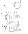
- FIG. 1is a perspective view showing the unmanned air vehicle system of the present embodiment.
- FIG. 2is a schematic diagram schematically showing the unmanned air vehicle system of the present embodiment.
- FIG. 3is a diagram illustrating an example of a functional configuration of the unmanned air vehicle system according to the present embodiment.
- FIG. 4is a view of the unmanned air vehicle system of the present embodiment viewed along the width direction.
- FIG. 5is a perspective view showing the unmanned air vehicle of the present embodiment.
- FIG. 6is a diagram illustrating the connection between the motor and the battery according to the present embodiment.
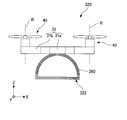
- FIG. 7is a perspective view showing an unmanned air vehicle system as another example of the present embodiment.
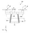
- FIG. 8is a view of an unmanned air vehicle, which is another example of the present embodiment, viewed along the depth direction.
- FIG. 9is a view of an unmanned air vehicle, which is another example of the present embodiment, viewed along the width direction.
- the Z axis direction shown as appropriate in each drawingis a direction parallel to the vertical direction.
- the Z-axis directionis simply referred to as “vertical direction Z”.
- the positive side in the Z-axis direction, that is, the upper side in the vertical directionis simply referred to as “upper side”
- the negative side in the Z-axis directionthat is, the lower side in the vertical direction is simply referred to as “lower side”.
- the X-axis direction and the Y-axis direction that are appropriately shown in the drawingsare directions orthogonal to the Z-axis direction and orthogonal to each other.
- the X-axis directionis called “depth direction X”
- the Y-axis directionis called “width direction Y”. Note that the depth direction and the width direction are simply names for explaining the relative positional relationship between the parts, and the actual layout relationship may be a layout relationship other than the layout relationship indicated by these names. Good.
- the unmanned aerial vehicle system 10 of this embodimentincludes a power transmission device 30 and an unmanned aerial vehicle 20.
- the power transmission apparatus 30is installed on the upper surface of the vending machine M, for example.
- the power transmission device 30includes a power transmission device main body 31 and a power transmission coil 70.
- the power transmission device main body 31has, for example, a rectangular parallelepiped shape that is flat in the width direction Y.
- the power transmission device main body 31is arranged at the end of one side in the width direction on the upper surface of the vending machine M.
- the power transmission coil 70has an annular shape centering on a second central axis J21 parallel to the width direction Y. That is, the second central axis J21 of the power transmission coil 70 extends in a direction orthogonal to the vertical direction Z.
- the power transmission coil 70is embedded in the power transmission device main body 31.
- the power transmission coil 70is a non-contact power feeding coil capable of transmitting power to a power receiving coil 60 described later.
- the dimension D of the power transmission coil 70is, for example, 648 mm or less.
- the dimension in the depth direction X of the vending machine Mis 648 mm or more and 819 mm or less
- the dimension of the vending machine M in the width direction Yis 870 mm. This is 1378 mm or less. Therefore, by setting the dimension D of the power transmission coil 70 within the above numerical range, the power transmission coil 70 can be installed on the upper surface of the vending machine M in any vending machine M as long as it is a representative standard. Is possible. Note that the dimension D of the power transmission coil 70 may be larger than 648 mm as long as it is within the dimension range of the typical standard of the vending machine M described above.
- the dimension H2 in the vertical direction Z of the power transmission coil 70is larger than the dimension H1 in the vertical direction Z of the leg 22 described later. Therefore, as shown in FIG. 4, the entire leg portion 22 can be disposed inside the outer edge of the power transmission coil 70 when viewed along the width direction Y.
- the power transmission device 30further includes a power transmission unit 32. Electric power is supplied to the power transmission unit 32 from an external power source 36.
- the power source 36may be a DC power source or an AC power source such as a commercial power source.
- the power transmission unit 32includes a power transmission power supply unit 33, a power transmission communication unit 35, and a power transmission control unit 34.
- the power transmission power supply unit 33outputs the power supplied from the power supply 36 to the power transmission coil 70 based on the control of the power transmission control unit 34.
- the power transmission communication unit 35includes, for example, an infrared sensor and receives infrared light for communication emitted from a power reception communication unit 65 (described later) provided in the unmanned air vehicle 20. Further, the power transmission communication unit 35 may emit infrared light for communication to the power reception communication unit 65 of the unmanned air vehicle 20.
- the power transmission control unit 34controls power supply by the power transmission coil 70 based on the infrared light received by the power transmission communication unit 35.
- the unmanned air vehicle 20includes a main body portion 21, a propulsion unit 40, a battery 50, a leg portion 22, a connecting beam portion 23, and a power receiving coil 60.
- the relative positional relationship of each part of the unmanned air vehicle 20will be described in the case where the posture of the unmanned air vehicle 20 is the posture shown in FIGS. 4 and 5 unless otherwise specified.
- the main body 21has a base 21a and an arm 21b.
- the base portion 21aextends along a plane orthogonal to the vertical direction Z.
- the shape seen from the upper side of the base 21ais substantially circular.
- the arm portion 21bhas a quadrangular prism shape extending substantially radially from the base portion 21a in a direction orthogonal to the vertical direction Z.
- a total of four arm portions 21bare provided side by side in the depth direction X, two on each side in the width direction Y of the base portion 21a.
- the propulsion unit 40is attached to the main body 21.
- a plurality of propulsion units 40are provided.
- the plurality of propulsion units 40are respectively provided at the tips of the arm portions 21b. That is, a total of four propulsion units 40 are provided, for example, two in the depth direction X on each side of the width direction Y of the main body 21.
- the propulsion unit 40includes a motor 41 and a rotary blade 42.
- the motor 41is disposed on the upper surface of the tip of the arm portion 21b.
- the rotor blade 42is fixed to the shaft of the motor 41.
- the motor 41rotates the rotating blade 42 around the rotation axis R by rotating the shaft.
- the rotation axis Rextends in the vertical direction Z.
- the unmanned air vehicle 20obtains buoyancy from the propulsion unit 40 and also obtains propulsive force in a direction perpendicular to the vertical direction Z.
- the propulsion unit 40further includes a motor control unit 44.
- the motor control unit 44outputs electric power supplied from the battery 50 to the motor 41 based on information from a flight control unit (not shown).
- the battery 50is a rechargeable battery disposed in the main body 21.
- the battery 50is electrically connected to the propulsion unit 40 and supplies electric power to the propulsion unit 40.
- one battery 50is provided.
- One battery 50is electrically connected to the plurality of propulsion units 40 and supplies electric power to the plurality of propulsion units 40.
- the type of the battery 50is not particularly limited as long as it is a rechargeable battery.
- the leg portion 22is connected to the main body portion 21 on the lower side of the main body portion 21.
- a plurality of leg portions 22are provided. More specifically, a pair of leg portions 22 are provided via a gap in one direction orthogonal to the vertical direction Z.
- one directionis the width direction Y.
- the pair of leg portions 22has a frame shape that protrudes downward from the main body portion 21 and surrounds the first central axis J1 parallel to the width direction Y.
- the first central axis J1passes through the center in the depth direction X at the center in the vertical direction Z of the leg portion 22, for example.
- the distance in the width direction Y between the pair of leg portions 22is uniform over the entire vertical direction Z.
- the leg portion 22has a semicircular arc portion 22 a that protrudes upward, and a linear portion 22 b that extends linearly in the depth direction X.
- the top of the arc portion 22ais connected to the lower surface of the base portion 21a.
- the straight line portion 22bconnects the lower ends of the arc portion 22a.
- the leg part 22is a single member with the main-body part 21, for example.
- the main body 21 and the leg 22are made of resin, for example.
- the connecting beam portion 23has a rectangular column shape extending in the width direction Y.
- a pair of connecting beam portions 23are provided in the depth direction X via a gap.
- the pair of connecting beam portions 23connect the pair of leg portions 22 to each other. More specifically, the one connecting beam portion 23 connects the end portions on one side in the depth direction in the straight portions 22b of the pair of leg portions 22.
- the other connecting beam portion 23connects the end portions on the other side in the depth direction of the straight portions 22 b of the pair of leg portions 22.
- the leg portion 22 and the connecting beam portion 23are used, for example, for an application in which a transported object or the like carried by the unmanned air vehicle 20 is mounted on the unmanned air vehicle 20.
- the transported objectis hooked on, for example, the straight portion 22b and the connecting beam portion 23 and mounted on the unmanned air vehicle 20.
- the leg part 22is frame shape, it is easy to hook a conveyed product with respect to the leg part 22.
- FIG.when the unmanned air vehicle 20 flies, the air resistance applied to the unmanned air vehicle 20 can be reduced.
- the power receiving coil 60is a coil for non-contact power feeding. As shown in FIG. 2, the power receiving coil 60 is electrically connected to the battery 50. When a magnetic field generated by a current flowing through the power transmission coil 70 acts on the power receiving coil 60, a current flows through the power receiving coil 60. As a result, power can be supplied from the power receiving coil 60 to the battery 50, and the battery 50 can be charged. Accordingly, by bringing the unmanned air vehicle 20 closer to the power transmission device 30, non-contact power feeding can be performed by the power receiving coil 60 and the power transmission coil 70 without connecting the battery 50 to an external power source.
- non-contact electric power feedingcan be performed by the power receiving coil 60 and the power transmission coil 70, the structure of the unmanned air vehicle 20 and the structure of the power transmission device 30 can be simplified. As described above, charging of the battery 50 can be automated with a simple structure and control.
- the terminal connecting the battery and the external power sourcemay be exposed to the outside. For this reason, when the power transmission device is installed outdoors, the terminal may get wet with rain, which may cause a problem in charging the battery.
- the battery 50since it is not necessary to connect the battery 50 to an external power supply, it is not necessary to expose the terminal to the outside. Therefore, even if the power transmission device 30 is installed outdoors, the battery 50 can be suitably charged. Further, since the charging of the battery 50 can be automated, the battery 50 can be charged as long as the unmanned air vehicle 20 is movable even in a place where it is difficult for a person to enter.
- the power receiving coil 60is provided on the leg portion 22. Therefore, it is not necessary to separately provide a portion where the power receiving coil 60 is provided, and the unmanned air vehicle 20 can be reduced in size and weight. Further, it is not necessary to change the shape of the unmanned air vehicle 20.
- the power receiving coil 60is provided in a frame shape along the leg portion 22. Therefore, it is easy to provide the power receiving coil 60 on the leg portion 22 while obtaining the above-described effect by using the leg portion 22 as a frame shape.
- the power receiving coil 60is also a frame shape surrounding the first central axis J1 as shown in FIG.
- the power receiving coil 60extends in a semicircular shape that is convex upward.
- the unmanned air vehicle 20charges the battery 50 with the power receiving coil 60 overlapped with the power transmitting coil 70 in the width direction Y in a state where the unmanned air vehicle 20 flies to a position away from the upper surface of the vending machine M, for example. .
- the battery 50can be charged easily.
- the unmanned air vehicle 20may charge the battery 50 in a state of landing on the upper surface of the vending machine M.
- the power receiving coil 60 and the power transmitting coil 70are coils for non-contact power feeding by a magnetic field resonance method.
- a currentcan be generated in the power receiving coil 60 regardless of the relative posture between the power receiving coil 60 and the power transmitting coil 70. Therefore, it is easy to charge the battery 50 regardless of the attitude of the unmanned air vehicle 20 with respect to the power transmission device 30 and the attitude of the power receiving coil 60 with respect to the unmanned air vehicle 20.
- the battery 50can be easily charged by simply bringing the unmanned air vehicle 20 closer to the power transmission device 30. Therefore, automatic charging of the battery 50 can be realized by simpler control of the unmanned air vehicle 20.
- the power receiving coil 60is embedded in the leg portion 22. Therefore, the leg portion 22 can be made by insert molding in which resin is poured in a state where the power receiving coil 60 is inserted into the mold. Accordingly, the unmanned air vehicle 20 can be easily manufactured.
- the power receiving coil 60is provided in each of the plurality of leg portions 22. Therefore, the battery 50 can be charged by the current generated in the plurality of power receiving coils 60.
- the plurality of power receiving coils 60are electrically connected to one battery 50, so that one battery 50 can be charged by current generated in the plurality of power receiving coils 60. it can. Therefore, the battery 50 can be charged more quickly.
- the dimension in the depth direction X and the dimension in the vertical direction Z of the power reception coil 60are smaller than the outer diameter of the power transmission coil 70. Therefore, when the unmanned air vehicle 20 is brought close to the power transmission device 30, the power receiving coil 60 is easily placed in the magnetic field generated by the power transmitting coil 70, and a current is easily generated in the power receiving coil 60. Further, as described above, since the dimension H2 of the power transmission coil 70 is larger than the dimension H1 of the leg part 22, the entire leg part 22 is arranged inward of the outer edge of the power transmission coil 70 when viewed along the width direction Y. Cheap. Therefore, it is easy to arrange the entire power receiving coil 60 provided on the leg 22 inside the outer edge of the power transmitting coil 70.
- the unmanned air vehicle 20is moved to one side in the width direction Y of the power transmission device 30, so that FIG.
- the entire two power receiving coils 60can be arranged in the width direction Y and arranged on the inner side of the outer edge of the power transmitting coil 70.
- a single power transmission coil 70can generate a current in all of the plurality of power reception coils 60. Therefore, it is not necessary to provide a plurality of power transmission coils 70, and the structure of the power transmission device 30 can be simplified.
- the battery 50can be charged more quickly.
- the unmanned air vehicle 20further includes a switching circuit 43.
- the switching circuit 43is provided between two wires that connect the two terminals of the battery 50 and the two terminals of the motor 41.
- the switching circuit 43connects two wires to each other in the ON state. Thereby, the switching circuit 43 connects and short-circuits the terminals of the motor 41 in the ON state. Therefore, the motor 41 can be prevented from rotating by turning the switching circuit 43 to the ON state. Thereby, when the motor 41 is stopped and the battery 50 is charged, it is possible to prevent the motor 41 from malfunctioning due to the magnetic field generated by the power transmission coil 70.
- the unmanned air vehicle 20further includes a power receiving unit 62 and a battery control unit 51.
- the power reception unit 62includes a power reception power supply unit 63, a power reception communication unit 65, and a power reception control unit 64.
- the power receiving power supply unit 63outputs the power supplied from the power receiving coil 60 to the battery control unit 51 based on the control of the power receiving control unit 64.
- the power reception communication unit 65includes, for example, a light source that emits infrared light for communication and the like, and emits infrared light based on the control of the power reception control unit 64.
- the power receiving communication unit 65receives infrared light emitted from the power transmission communication unit 35.
- the power reception control unit 64controls the power reception communication unit 65. Specifically, the power reception control unit 64 outputs a power supply start request signal and a power supply stop request signal to the power reception communication unit 65. The power reception communication unit 65 transmits the power supply start request signal and the power supply stop request signal output from the power reception control unit 64 to the power transmission device 30.
- the battery control unit 51includes a charging power supply unit 53 and a charging control unit 52.
- the charging power supply unit 53outputs the power supplied from the power receiving unit 62 to the battery 50 based on the control of the charging control unit 52.
- the charge control unit 52controls the start and stop of charging the battery 50.
- the battery 50, the leg portion 22, the connecting beam portion 23, the power receiving coil 60, the power receiving unit 62, and the battery control unit 51constitute a battery system 80. That is, the battery system 80 includes a battery 50, a leg portion 22, a connecting beam portion 23, a power receiving coil 60, a power receiving unit 62, and a battery control unit 51.
- the present inventionis not limited to the above-described embodiment, and the following other configurations may be employed.
- the rotation axis R about which the rotating blade 42 rotatesmay extend in a direction other than the vertical direction Z.
- the rotation axis Rmay extend in a direction orthogonal to the vertical direction Z.
- the extending directions of the rotation axis R in the plurality of rotor blades 42may be different from each other.
- the number of propulsion units 40is not particularly limited.
- a plurality of batteries 50may be provided.
- a configuration in which one receiving coil 60 is connected to each of the plurality of batteries 50may be used, or a configuration in which a plurality of receiving coils 60 are connected may be used.
- the battery 50may be provided for each propulsion unit 40. Further, the switching circuit 43 may not be provided.
- the power receiving coil 60 and the power transmitting coil 70may be non-contact power feeding coils other than the magnetic field resonance method.
- the power reception coil 60 and the power transmission coil 70may be, for example, electromagnetic induction type non-contact power supply coils, or radio wave reception type non-contact power supply coils.
- powercan be supplied even if the power receiving coil 60 and the power transmitting coil 70 are misaligned. Therefore, even when the power receiving coil 60 is located outside the outer edge of the power transmitting coil 70, power can be supplied.
- the unmanned air vehicledoes not necessarily have to land in the outer edge of the power transmission coil 70.
- the power transmission device 30may be configured as a power transmission device 130 shown in FIG.
- the power transmission device main body 131 of the power transmission device 130 in the unmanned air vehicle system 110has a rectangular parallelepiped shape that is flat in the vertical direction Z, for example.
- the power transmission device main body 131is disposed on the upper surface of the vending machine M.
- the power transmission coil 170has an annular shape centering on a second central axis J22 that is parallel to the vertical direction Z. In this configuration, the first central axis J1 surrounded by the power receiving coil 60 of the unmanned air vehicle 20 and the second central axis J22 of the power transmission coil 170 are substantially orthogonal.
- the battery 50can be charged by generating a current in the power receiving coil 60 by using magnetic resonance type non-contact power feeding.
- the power transmission device 130has, for example, a configuration in which the power transmission device 30 illustrated in FIG. 1 is rotated by 90 ° about an axis parallel to the depth direction X.
- the dimension in the depth direction X of the power transmission coil 170is 648 mm or less, and the dimension W in the width direction Y of the power transmission coil 170 is 870 mm or less.
- the power transmission coil 170can be installed on the upper surface of the vending machine M in any vending machine M as long as it is a representative standard.
- the unmanned air vehicle 20charges the battery 50 while being landed on the upper surface of the power transmission device main body 131, for example.
- the lower surface of the frame portion 24 constituted by the leg portion 22 and the connecting beam portion 23comes into contact with the landing surface. Therefore, by landing the unmanned air vehicle 20 on the upper surface of the power transmission device main body 131, the leg portion 22 can be brought closer to the upper surface of the power transmission device main body 131. Thereby, the power reception coil 60 can be brought close to the power transmission coil 170 embedded in the power transmission apparatus main body 131. Therefore, it is easier to charge the battery 50.
- the outer diameter of the power transmission coil 70 of the power transmission device 30may be larger than the maximum dimension of the unmanned air vehicle 20.
- the battery 50can be charged by simultaneously generating currents for the plurality of power reception coils 60.
- the “maximum size of the unmanned air vehicle”includes the length of the longest virtual line segment connecting the two arbitrary points in the unmanned air vehicle.
- the installation place of the power transmission apparatus 30is not specifically limited. The dimensions of the power transmission coil 70 can be appropriately determined according to the installation location of the power transmission device 30. A part or the whole of the power transmission coil 70 may be exposed from the power transmission device main body 31.
- the power receiving coil 60may be provided only on a part of the plurality of leg portions 22. That is, in the above-described embodiment, the power receiving coil 60 may be provided only on one of the pair of leg portions 22.
- the shape of the leg 22, the shape of the power reception coil 60, and the shape of the power transmission coil 70are not particularly limited, and may be a rectangular shape, a polygonal shape, or an elliptical shape. .
- the shape of the leg portion 22may be a plate shape instead of a frame shape, for example.
- the shape of the power receiving coil 60 and the shape of the power transmitting coil 70may be different from each other.
- the first central axis J1 surrounded by the leg portion 22 and the power receiving coil 60may be parallel to the vertical direction Z.
- the number of power receiving coils 60 mounted on the unmanned air vehicle 20is not particularly limited. Further, the number of leg portions 22 is not particularly limited.
- the power receiving coil is provided on the leg portionmeans that at least a part of the power receiving coil is provided on the leg portion. That is, in the above-described embodiment, the entire power receiving coil 60 is provided on the leg portion 22, but is not limited thereto.
- the power receiving coil 60may be provided in the frame portion 24. In this case, the power receiving coil 60 has a rectangular frame shape along the frame portion 24, and a part of the power receiving coil 60 is provided on the straight portion 22 b of the leg portion 22.
- the leg portion 22may have a configuration like the leg portion 222 shown in FIG.
- the distance in the width direction Y between the pair of legs 222increases toward the lower side. That is, the pair of leg portions 222 protrudes downward from the main body portion 21 in a direction inclined with respect to the vertical direction Z. Therefore, the power receiving coil 260 provided in the leg portion 222 is also inclined with respect to the vertical direction Z. In this case, the power receiving coil 260 and the power transmitting coil 70 are likely to be inclined with respect to each other, but the battery 50 can be suitably charged by employing non-contact power feeding by a magnetic field resonance method.
- the battery 50can be easily charged as described above by simply providing the power receiving coil 260 along the leg portion 222. Is possible. That is, the battery 50 can be easily charged while the power receiving coil 60 is provided on the leg portion 222 without changing the inclination of the leg portion 222 with respect to the main body portion 21.
- leg portion 22may be detachable from the main body portion 21. In this case, it is easy to replace the battery system 80 including the battery 50, the leg portion 22, the connecting beam portion 23, and the power receiving coil 60. Moreover, the connection beam part 23 does not need to be provided.
- the power receiving coil is provided on the leg portionincludes a case where the leg portion is the power receiving coil itself, such as the leg portion 322 shown in FIG. 9.
- the leg portion 322 of the unmanned air vehicle 320includes a power receiving coil 360.
- the power receiving coil 360is fixed to the main body portion 21. According to this configuration, since the power receiving coil 360 can be used as the leg portion 322, the leg portion 322 can be made by making the power receiving coil 360. Therefore, it is easy to make the leg portion 322 provided with the power receiving coil 360, and the unmanned air vehicle 320 can be easily manufactured.
- the power transmission communication unit 35 and the power reception communication unit 65may perform communication constantly or at predetermined intervals.
- the power reception unit 62may receive power reception state information indicating a state of power reception by the power reception coil 60 from the power transmission communication unit 35.
- the power transmission communication unit 35 and the power reception communication unit 65are not limited to the method using infrared light, and other methods such as wireless communication may be adopted.
- the unmanned air vehicle 20performs horizontal movement or rotational movement based on the power reception state information received by the power reception communication unit 65. That is, the unmanned air vehicle 20 moves when the motor control unit 44 controls the motor 41 based on the power reception state information indicating the state of power reception by the power reception coil 60.
- the power receiving unit 62may be directly connected to the motor control unit 44. In this configuration, power is directly supplied from the power receiving unit 62 to the motor control unit 44. In this configuration, the power reception control unit 64 may determine whether to supply power from the battery 50 to the motor control unit 44 or whether to supply power from the power reception unit 62 to the motor control unit 44, for example.
- the use of the unmanned air vehicle and the unmanned air vehicle system of the above-described embodimentis not particularly limited.
- the above-described configurationscan be appropriately combined within a range that does not contradict each other.
Landscapes
- Engineering & Computer Science (AREA)
- Power Engineering (AREA)
- Mechanical Engineering (AREA)
- Transportation (AREA)
- Aviation & Aerospace Engineering (AREA)
- Computer Networks & Wireless Communication (AREA)
- Chemical & Material Sciences (AREA)
- Combustion & Propulsion (AREA)
- Sustainable Energy (AREA)
- Sustainable Development (AREA)
- Life Sciences & Earth Sciences (AREA)
- Signal Processing (AREA)
- Charge And Discharge Circuits For Batteries Or The Like (AREA)
Abstract
Description
Translated fromJapanese本発明は、無人飛行体、無人飛行体システム、およびバッテリシステムに関する。The present invention relates to an unmanned air vehicle, an unmanned air vehicle system, and a battery system.
給電ワイヤから供給された電力によって飛行するマルチコプタが知られる。例えば、特許文献1には、照明システムに備えられたマルチコプタが記載される。A multi-copter that flies by power supplied from a power supply wire is known. For example, Patent Document 1 describes a multicopter provided in an illumination system.
上記のような給電ワイヤによる電力の供給では、マルチコプタは、給電ワイヤの長さの範囲内でしか飛行することができず、移動範囲が制限される問題があった。これに対して、マルチコプタに搭載されたバッテリから供給された電力によって飛行する方法を採用すれば、マルチコプタの移動範囲を広げることができる。この場合、バッテリの残量が低下した場合、あるいはバッテリが切れた場合等に、バッテリを充電する、あるいはバッテリを交換する必要がある。In the power supply using the power supply wire as described above, the multicopter can only fly within the range of the length of the power supply wire, and there is a problem that the range of movement is limited. On the other hand, if the method of flying with the electric power supplied from the battery mounted on the multicopter is adopted, the moving range of the multicopter can be expanded. In this case, it is necessary to charge the battery or replace the battery when the remaining amount of the battery decreases or when the battery runs out.
バッテリの充電あるいは交換は、人の手を介して行うと手間が大きいため、自動化されることが望まれる。しかし、例えば、バッテリに外部電源を接続してバッテリを充電する場合、マルチコプタを自動で外部電源と接続させる必要があり、マルチコプタの制御が複雑化しやすい。一方、バッテリを自動で交換する場合、バッテリを交換するための装置が、複雑化および大型化しやすい。以上のことから、バッテリの充電あるいは交換を自動化する場合、マルチコプタあるいは充電設備の製造コストが増加する問題がある。It is desired to automate the charging or replacement of the battery because it takes a lot of time and effort if done through human hands. However, for example, when charging the battery by connecting an external power supply to the battery, it is necessary to automatically connect the multicopter to the external power supply, and the control of the multicopter tends to be complicated. On the other hand, when the battery is automatically replaced, an apparatus for replacing the battery is likely to be complicated and large. From the above, when automating the charging or replacement of the battery, there is a problem that the manufacturing cost of the multicopter or the charging facility increases.
本発明は、上記事情に鑑みて、簡単な構造および制御でバッテリの充電を自動化できる無人飛行体、そのような無人飛行体を備える無人飛行体システム、およびそのような無人飛行体に備えられるバッテリシステムを提供することを目的の一つとする。In view of the above circumstances, the present invention provides an unmanned air vehicle capable of automating battery charging with a simple structure and control, an unmanned air vehicle system including such an unmanned air vehicle, and a battery provided in such an unmanned air vehicle. One of the purposes is to provide a system.
本発明の無人飛行体の一つの態様は、本体部と、回転翼および前記回転翼を回転軸回りに回転させるモータを有し、前記本体部に取り付けられる推進ユニットと、前記推進ユニットに電力を供給する充電式のバッテリと、前記本体部の鉛直方向下側において、前記本体部と繋がる脚部と、前記バッテリと電気的に接続され、前記脚部に設けられる非接触給電用の受電コイルと、を備える。One aspect of the unmanned air vehicle of the present invention includes a main body portion, a rotating wing and a motor that rotates the rotating wing about a rotation axis, a propulsion unit attached to the main body portion, and power to the propulsion unit. A rechargeable battery to be supplied; a leg portion connected to the main body portion on a lower side in the vertical direction of the main body portion; a non-contact power receiving coil provided on the leg portion that is electrically connected to the battery; .
本発明の無人飛行体システムの一つの態様は、上記無人飛行体と、前記受電コイルに対して送電可能な非接触給電用の送電コイルを有する送電装置と、を備える。One aspect of the unmanned air vehicle system of the present invention includes the unmanned air vehicle and a power transmission device having a power transmission coil for non-contact power feeding that can transmit power to the power receiving coil.
本発明のバッテリシステムの一つの態様は、本体部と、回転翼および前記回転翼を回転軸回りに回転させるモータを有し、前記本体部に取り付けられる推進ユニットと、を備える無人飛行体のバッテリシステムであって、前記推進ユニットに電力を供給する充電式のバッテリと、前記本体部の鉛直方向下側において、前記本体部と繋がる脚部と、前記バッテリと電気的に接続され、前記脚部に設けられる非接触給電用の受電コイルと、を備える。One aspect of the battery system of the present invention is a battery of an unmanned air vehicle comprising: a main body portion; and a propulsion unit that includes a rotor blade and a motor that rotates the rotor blade around a rotation axis and is attached to the main body portion. A rechargeable battery for supplying power to the propulsion unit, a leg connected to the main body on the lower side in the vertical direction of the main body, and the leg electrically connected to the battery And a receiving coil for non-contact power feeding provided in the.
本発明の一つの態様によれば、簡単な構造および制御でバッテリの充電を自動化できる無人飛行体、そのような無人飛行体を備える無人飛行体システム、およびそのような無人飛行体に備えられるバッテリシステムが提供される。According to one aspect of the present invention, an unmanned air vehicle capable of automating battery charging with a simple structure and control, an unmanned air vehicle system including such an unmanned air vehicle, and a battery provided in such an unmanned air vehicle A system is provided.
各図に適宜示すZ軸方向は、鉛直方向と平行な方向である。Z軸方向を単に「鉛直方向Z」と呼ぶ。また、Z軸方向の正の側、すなわち鉛直方向上側を単に「上側」と呼び、Z軸方向の負の側、すなわち鉛直方向下側を単に「下側」と呼ぶ。また、各図に適宜示すX軸方向およびY軸方向は、Z軸方向と直交し、かつ、互いに直交する方向である。X軸方向を「奥行方向X」と呼び、Y軸方向を「幅方向Y」と呼ぶ。なお、奥行方向および幅方向とは、単に各部の相対位置関係を説明するための名称であり、実際の配置関係等は、これらの名称で示される配置関係等以外の配置関係等であってもよい。The Z axis direction shown as appropriate in each drawing is a direction parallel to the vertical direction. The Z-axis direction is simply referred to as “vertical direction Z”. The positive side in the Z-axis direction, that is, the upper side in the vertical direction is simply referred to as “upper side”, and the negative side in the Z-axis direction, that is, the lower side in the vertical direction is simply referred to as “lower side”. In addition, the X-axis direction and the Y-axis direction that are appropriately shown in the drawings are directions orthogonal to the Z-axis direction and orthogonal to each other. The X-axis direction is called “depth direction X”, and the Y-axis direction is called “width direction Y”. Note that the depth direction and the width direction are simply names for explaining the relative positional relationship between the parts, and the actual layout relationship may be a layout relationship other than the layout relationship indicated by these names. Good.
図1から図3に示すように、本実施形態の無人飛行体システム10は、送電装置30と、無人飛行体20と、を備える。本実施形態において送電装置30は、例えば、自動販売機Mの上面に設置される。送電装置30は、送電装置本体31と、送電コイル70と、を有する。送電装置本体31は、例えば、幅方向Yに扁平な直方体状である。送電装置本体31は、自動販売機Mの上面における幅方向一方側の端部に配置される。As shown in FIGS. 1 to 3, the unmanned
図1に示すように、送電コイル70は、幅方向Yと平行な第2中心軸J21を中心とする円環状である。すなわち、送電コイル70の第2中心軸J21は、鉛直方向Zと直交する方向に延びる。送電コイル70は、送電装置本体31に埋め込まれる。送電コイル70は、後述する受電コイル60に対して送電可能な非接触給電用のコイルである。第2中心軸J21および鉛直方向Zの両方と直交する奥行方向Xにおいて、送電コイル70の寸法Dは、例えば、648mm以下である。As shown in FIG. 1, the
ここで、自動販売機Mの代表的な規格においては、例えば、自動販売機Mの奥行方向Xの寸法は、648mm以上、819mm以下であり、自動販売機Mの幅方向Yの寸法は、870mm以上、1378mm以下である。そのため、送電コイル70の寸法Dを上記数値範囲とすることで、代表的な規格であればいずれの自動販売機Mであっても、送電コイル70を自動販売機Mの上面に設置することが可能である。なお、上述した自動販売機Mの代表的な規格の寸法範囲内であれば、送電コイル70の寸法Dは648mmより大きくてもよい。Here, in a typical standard of the vending machine M, for example, the dimension in the depth direction X of the vending machine M is 648 mm or more and 819 mm or less, and the dimension of the vending machine M in the width direction Y is 870 mm. This is 1378 mm or less. Therefore, by setting the dimension D of the
送電コイル70の鉛直方向Zの寸法H2は、後述する脚部22の鉛直方向Zの寸法H1よりも大きい。そのため、図4に示すように、脚部22の全体を、幅方向Yに沿って視て送電コイル70の外縁よりも内側に配置することが可能である。The dimension H2 in the vertical direction Z of the
図3に示すように、送電装置30は、送電ユニット32をさらに有する。送電ユニット32には、外部の電源36から電力が供給される。電源36は、DC電源であってもよいし、商用電源等の交流電源であってもよい。送電ユニット32は、送電電源部33と、送電通信部35と、送電制御部34と、を有する。As shown in FIG. 3, the
送電電源部33は、送電制御部34の制御に基づいて、電源36から供給された電力を送電コイル70に出力する。送電通信部35は、例えば、赤外線センサ等を有し、無人飛行体20に設けられた後述する受電通信部65から射出される通信用の赤外光を受光する。また、送電通信部35は、無人飛行体20の受電通信部65に通信用の赤外光を射出してもよい。送電制御部34は、送電通信部35が受光する赤外光に基づいて、送電コイル70による電力供給を制御する。The power transmission
図2から図5に示すように、無人飛行体20は、本体部21と、推進ユニット40と、バッテリ50と、脚部22と、連結梁部23と、受電コイル60と、を備える。以下の説明において無人飛行体20の各部の相対位置関係は、特に断りのない限り、無人飛行体20の姿勢が図4および図5に示す姿勢である場合について説明する。2 to 5, the
図5に示すように、本体部21は、基部21aと、腕部21bと、を有する。基部21aは、鉛直方向Zと直交する平面に沿って拡がる。基部21aの上側から視た形状は、略円形状である。腕部21bは、鉛直方向Zと直交する方向において基部21aから略放射状に延びる四角柱状である。腕部21bは、例えば、基部21aの幅方向Yの両側に2つずつ奥行方向Xに並んで、合計4つ設けられる。As shown in FIG. 5, the
推進ユニット40は、本体部21に取り付けられる。本実施形態において推進ユニット40は、複数設けられる。複数の推進ユニット40は、腕部21bの先端にそれぞれ設けられる。すなわち、推進ユニット40は、例えば、本体部21の幅方向Yの両側に2つずつ奥行方向Xに並んで、合計4つ設けられる。推進ユニット40は、モータ41と、回転翼42と、を有する。モータ41は、腕部21bの先端の上面に配置される。回転翼42は、モータ41のシャフトに固定される。モータ41は、シャフトを回転させることで、回転翼42を回転軸R回りに回転させる。本実施形態において回転軸Rは、鉛直方向Zに延びる。回転翼42が回転することによって、無人飛行体20は、推進ユニット40から浮力を得るとともに、鉛直方向Zと直交する方向への推進力を得る。図3に示すように、推進ユニット40は、モータ制御部44をさらに有する。モータ制御部44は、図示しない飛行制御部からの情報に基づいて、バッテリ50から供給される電力をモータ41に出力する。The
図2に示すように、バッテリ50は、本体部21に配置される充電式のバッテリである。バッテリ50は、推進ユニット40と電気的に接続され、推進ユニット40に電力を供給する。本実施形態においてバッテリ50は、例えば、1つ設けられる。1つのバッテリ50は、複数の推進ユニット40と電気的に接続され、複数の推進ユニット40に電力を供給する。バッテリ50の種類は、充電式のバッテリであれば特に限定されない。As shown in FIG. 2, the
図5に示すように、脚部22は、本体部21の下側において、本体部21と繋がる。本実施形態において脚部22は、複数設けられる。より詳細には、脚部22は、鉛直方向Zと直交する一方向に隙間を介して一対設けられる。本実施形態において一方向は、幅方向Yである。一対の脚部22は、本体部21から下側に突出し、かつ、幅方向Yと平行な第1中心軸J1を囲む枠状である。第1中心軸J1は、例えば、脚部22の鉛直方向Zの中心における奥行方向Xの中心を通る。本実施形態において一対の脚部22同士の幅方向Yの距離は、鉛直方向Zの全体に亘って一様である。As shown in FIG. 5, the
図4に示すように、脚部22は、上側に凸となる半円弧状の円弧部22aと、奥行方向Xに直線状に延びる直線部22bと、を有する。円弧部22aの頂部は、基部21aの下面に繋がる。直線部22bは、円弧部22aの下端同士を繋ぐ。本実施形態において脚部22は、例えば、本体部21と単一の部材である。本体部21および脚部22は、例えば、樹脂製である。As shown in FIG. 4, the
図5に示すように、連結梁部23は、幅方向Yに延びる四角柱状である。連結梁部23は、奥行方向Xに隙間を介して一対設けられる。一対の連結梁部23は、一対の脚部22同士を繋ぐ。より詳細には、一方の連結梁部23は、一対の脚部22の直線部22bにおける奥行方向一方側の端部同士を繋ぐ。他方の連結梁部23は、一対の脚部22の直線部22bにおける奥行方向他方側の端部同士を繋ぐ。一対の脚部22の直線部22bと一対の連結梁部23とが繋がることで、鉛直方向Zと平行な軸を囲む矩形枠状の枠部24が構成される。As shown in FIG. 5, the connecting
脚部22および連結梁部23は、例えば、無人飛行体20によって運搬される運搬物等を無人飛行体20に搭載する用途に用いられる。運搬物は、例えば、直線部22bおよび連結梁部23等に引っ掛けられて、無人飛行体20に搭載される。本実施形態では、脚部22が枠状であるため、脚部22に対して運搬物を引っ掛けやすい。また、無人飛行体20が飛行する際に、無人飛行体20に加わる空気抵抗を小さくできる。The
受電コイル60は、非接触給電用のコイルである。図2に示すように、受電コイル60は、バッテリ50と電気的に接続される。送電コイル70に電流が流れることで生じる磁界が受電コイル60に作用すると、受電コイル60に電流が流れる。これにより、受電コイル60からバッテリ50に給電することができ、バッテリ50を充電できる。したがって、無人飛行体20を送電装置30に近づけることで、バッテリ50を外部電源に接続することなく、受電コイル60と送電コイル70とによって非接触給電を行うことができる。また、受電コイル60と送電コイル70とによって非接触給電を行えるため、無人飛行体20の構造および送電装置30の構造を簡単化できる。以上により、簡単な構造および制御でバッテリ50の充電を自動化できる。The
また、例えば、無人飛行体を自動で移動させてバッテリと外部電源とを接続する構成とする場合、バッテリと外部電源とを接続する端子を外部に露出させる場合がある。そのため、屋外に送電装置を設置すると端子が雨で濡れる等して、バッテリの充電に不具合が生じる場合がある。これに対して本実施形態によれば、バッテリ50を外部電源に接続する必要がないため、端子を外部に露出させる必要がない。したがって、送電装置30を屋外に設置しても、バッテリ50の充電を好適に行うことができる。また、バッテリ50の充電を自動化できることで、人が入りにくいような場所等であっても、無人飛行体20が移動可能な場所であればバッテリ50の充電を行うことができる。Also, for example, when the unmanned air vehicle is automatically moved to connect the battery and the external power source, the terminal connecting the battery and the external power source may be exposed to the outside. For this reason, when the power transmission device is installed outdoors, the terminal may get wet with rain, which may cause a problem in charging the battery. On the other hand, according to this embodiment, since it is not necessary to connect the
受電コイル60は、脚部22に設けられる。そのため、受電コイル60を設ける部分を別途設ける必要がなく、無人飛行体20を小型化かつ軽量化できる。また、無人飛行体20の形状を変更する必要がない。受電コイル60は、脚部22に沿って枠状に設けられる。そのため、脚部22を枠状として上述した効果を得つつも、受電コイル60を脚部22に設けやすい。本実施形態では、脚部22が幅方向Yに延びる第1中心軸J1を囲む枠状であるため、図4に示すように、受電コイル60も第1中心軸J1を囲む枠状である。受電コイル60は、上側に凸となる半円状に延びる。The
本実施形態において無人飛行体20は、例えば、自動販売機Mの上面から上側に離れた位置に飛行した状態で、受電コイル60を送電コイル70と幅方向Yに重ねてバッテリ50の充電を行う。これにより、脚部22に運搬物が搭載され、運搬物が脚部22より下側に配置される場合であっても、バッテリ50の充電を容易に行うことができる。なお、無人飛行体20は、自動販売機Mの上面に着地した状態でバッテリ50の充電を行ってもよい。In the present embodiment, the
本実施形態において受電コイル60および送電コイル70は、磁界共鳴方式による非接触給電用のコイルである。磁界共鳴方式による非接触給電を用いる場合、受電コイル60を送電コイル70に近づければ、受電コイル60と送電コイル70との相対姿勢によらず、受電コイル60に電流を生じさせることができる。そのため、送電装置30に対する無人飛行体20の姿勢、および無人飛行体20に対する受電コイル60の姿勢によらず、バッテリ50を充電しやすい。これにより、無人飛行体20の位置制御の精度が比較的低い場合であっても、無人飛行体20を単に送電装置30に近づけることによって、バッテリ50の充電を行いやすい。したがって、より簡単な無人飛行体20の制御によって、バッテリ50の自動充電を実現できる。In the present embodiment, the
本実施形態において受電コイル60は、脚部22に埋め込まれる。そのため、金型に受電コイル60を挿入した状態で樹脂を流し込むインサート成形によって、脚部22を作ることができる。したがって、無人飛行体20の製造を容易にできる。In the present embodiment, the
受電コイル60は、複数の脚部22のそれぞれに設けられる。そのため、複数の受電コイル60に生じた電流によって、バッテリ50の充電を行うことができる。本実施形態では、図2に示すように、複数の受電コイル60は、1つのバッテリ50に電気的に接続されるため、複数の受電コイル60に生じる電流によって1つのバッテリ50を充電することができる。したがって、バッテリ50をより早く充電することができる。The
図4に示すように、受電コイル60の奥行方向Xの寸法および鉛直方向Zの寸法は、送電コイル70の外径よりも小さい。そのため、無人飛行体20を送電装置30に近づけた際に、受電コイル60を送電コイル70によって生じる磁界内に入れやすく、受電コイル60に電流を生じさせやすい。また、上述したように送電コイル70の寸法H2が脚部22の寸法H1よりも大きいことで、脚部22の全体を幅方向Yに沿って視て送電コイル70の外縁よりも内側に配置しやすい。そのため、脚部22に設けられた受電コイル60の全体を送電コイル70の外縁よりも内側に配置しやすい。As shown in FIG. 4, the dimension in the depth direction X and the dimension in the vertical direction Z of the
本実施形態では、一対の脚部22は幅方向Yに隙間を介して配置されるため、無人飛行体20を送電装置30の幅方向Yのいずれか一方側に移動させることで、図4に示すように、2つの受電コイル60の全体を幅方向Yに重ねて、送電コイル70の外縁よりも内側に配置できる。これにより、1つの送電コイル70によって、複数の受電コイル60のすべてに電流を生じさせることができる。したがって、送電コイル70を複数設ける必要がなく、送電装置30の構造を簡単化できる。また、すべての受電コイル60に同時に電流を生じさせることができるため、バッテリ50をより早く充電することができる。In the present embodiment, since the pair of
図6に示すように、無人飛行体20は、スイッチング回路43をさらに備える。スイッチング回路43は、バッテリ50の2つの端子とモータ41の2つの端子とをそれぞれ繋ぐ2本の配線同士の間に設けられる。スイッチング回路43は、ON状態において2本の配線同士を繋ぐ。これにより、スイッチング回路43は、ON状態においてモータ41の端子同士を繋いで短絡させる。そのため、スイッチング回路43をON状態とすることで、モータ41が回転することを阻止できる。これにより、モータ41を停止させてバッテリ50の充電を行う際に、送電コイル70によって生じる磁界によってモータ41が誤作動することを抑制できる。As shown in FIG. 6, the
図3に示すように、無人飛行体20は、受電ユニット62と、バッテリ制御ユニット51と、をさらに備える。受電ユニット62は、受電電源部63と、受電通信部65と、受電制御部64と、を有する。受電電源部63は、受電制御部64の制御に基づいて、受電コイル60から供給された電力をバッテリ制御ユニット51に出力する。受電通信部65は、例えば、通信用の赤外光等を射出する光源を有し、受電制御部64の制御に基づいて、赤外光を射出する。また、受電通信部65は、送電通信部35が射出する赤外光を受光する。As shown in FIG. 3, the
受電制御部64は、受電通信部65を制御する。具体的には、受電制御部64は、給電開始要求の信号および給電停止要求の信号を、受電通信部65に出力する。受電通信部65は、受電制御部64から出力された給電開始要求の信号および給電停止要求の信号を送電装置30に送信する。The power
バッテリ制御ユニット51は、充電電源部53と、充電制御部52と、を有する。充電電源部53は、充電制御部52の制御に基づいて、受電ユニット62から供給された電力をバッテリ50に出力する。充電制御部52は、バッテリ50への充電の開始および停止を制御する。The
本実施形態においては、バッテリ50と脚部22と連結梁部23と受電コイル60と受電ユニット62とバッテリ制御ユニット51とによってバッテリシステム80が構成される。すなわち、バッテリシステム80は、バッテリ50と、脚部22と、連結梁部23と、受電コイル60と、受電ユニット62と、バッテリ制御ユニット51と、を備える。In the present embodiment, the
本発明は上述の実施形態に限られず、以下の他の構成を採用することもできる。回転翼42が回転する回転軸Rは、鉛直方向Z以外の方向に延びてもよい。例えば、回転軸Rは、鉛直方向Zと直交する方向に延びてもよい。また、複数の回転翼42における回転軸Rの延びる方向は、互いに異なってもよい。また、推進ユニット40の数は、特に限定されない。The present invention is not limited to the above-described embodiment, and the following other configurations may be employed. The rotation axis R about which the
また、バッテリ50は、複数設けられてもよい。この場合、複数のバッテリ50のそれぞれに対して、1つずつ受電コイル60が接続される構成であってもよいし、複数ずつ受電コイル60が接続される構成であってもよい。バッテリ50は、推進ユニット40ごとに設けられてもよい。また、スイッチング回路43は、設けられなくてもよい。Further, a plurality of
また、受電コイル60および送電コイル70は、磁界共鳴方式以外の非接触給電用のコイルであってもよい。受電コイル60および送電コイル70は、例えば、電磁誘導方式の非接触給電用のコイルであってもよいし、電波受信方式の非接触給電用のコイルであってもよい。なお、磁界共鳴方式では、受電コイル60と送電コイル70同士の位置がずれていても給電可能である。そのため、受電コイル60が送電コイル70の外縁より外側に位置しても給電が可能である。必ずしも無人飛行体が送電コイル70の外縁内に着陸しなくてもよい。The
また、送電装置30は、図7に示す送電装置130のような構成であってもよい。図7に示すように、無人飛行体システム110において送電装置130の送電装置本体131は、例えば、鉛直方向Zに扁平な直方体状である。送電装置本体131は、自動販売機Mの上面に配置される。送電コイル170は、鉛直方向Zと平行な第2中心軸J22を中心とする円環状である。この構成においては、無人飛行体20の受電コイル60が囲む第1中心軸J1と送電コイル170の第2中心軸J22とは略直交した状態となる。この場合であっても、磁界共鳴方式の非接触給電を用いることで、受電コイル60に電流を生じさせてバッテリ50の充電を行うことができる。送電装置130は、例えば、図1に示す送電装置30を奥行方向Xと平行な軸回りに90°回転させた構成である。Further, the
送電コイル170の奥行方向Xの寸法は、648mm以下であり、送電コイル170の幅方向Yの寸法Wは、870mm以下である。これにより、代表的な規格であればいずれの自動販売機Mであっても、送電コイル170を自動販売機Mの上面に設置することが可能である。The dimension in the depth direction X of the
この構成において無人飛行体20は、例えば、送電装置本体131の上面に着地した状態で、バッテリ50の充電を行う。運搬物を搭載していない場合において無人飛行体20が着地すると、脚部22と連結梁部23とによって構成される枠部24の下面が着地面に接触する。そのため、送電装置本体131の上面に無人飛行体20を着地させることで、脚部22を送電装置本体131の上面に近づけることができる。これにより、受電コイル60を送電装置本体131に埋め込まれた送電コイル170に近づけることができる。したがって、よりバッテリ50を充電しやすい。In this configuration, the
また、送電装置30の送電コイル70の外径は、無人飛行体20の最大寸法より大きくてもよい。この場合、無人飛行体20の全体を送電コイル70の外縁よりも内側に配置しやすいため、複数の受電コイル60に対して同時に電流を生じさせて、バッテリ50の充電を行うことができる。なお、本明細書において「無人飛行体の最大寸法」とは、無人飛行体における任意の2点間を結ぶ仮想線分のうち最も長い仮想線分の長さを含む。また、送電装置30の設置場所は、特に限定されない。送電コイル70の寸法は、送電装置30の設置場所に応じて適宜決めることができる。送電コイル70の一部あるいは全体は、送電装置本体31から露出してもよい。Further, the outer diameter of the
また、複数の脚部22のうちの一部の脚部22のみに受電コイル60が設けられてもよい。すなわち、上述した実施形態においては、一対の脚部22のうちのいずれか一方の脚部22のみに受電コイル60が設けられてもよい。脚部22の形状、受電コイル60の形状、および送電コイル70の形状は、特に限定されず、矩形状であってもよいし、多角形状であってもよいし、楕円形状であってもよい。脚部22の形状は、枠状でなく、例えば、板状であってもよい。受電コイル60の形状と送電コイル70の形状とは、互いに異なってもよい。脚部22および受電コイル60が囲む第1中心軸J1は、鉛直方向Zに対して平行であってもよい。また、無人飛行体20に搭載される受電コイル60の数は、特に限定されない。また、脚部22の数は、特に限定されない。Further, the
また、本明細書において「受電コイルが脚部に設けられる」とは、受電コイルの少なくとも一部が脚部に設けられればよい。すなわち、上述した実施形態では、受電コイル60の全体が脚部22に設けられる構成としたが、これに限られない。例えば、受電コイル60は、枠部24に設けられてもよい。この場合、受電コイル60は、枠部24に沿った矩形枠状であり、受電コイル60の一部は、脚部22の直線部22bに設けられる。In addition, in this specification, “the power receiving coil is provided on the leg portion” means that at least a part of the power receiving coil is provided on the leg portion. That is, in the above-described embodiment, the entire
また、脚部22は、図8に示す脚部222のような構成であってもよい。図8に示すように、無人飛行体220において、一対の脚部222同士の幅方向Yの距離は、下側に向かうに従って大きくなる。すなわち、一対の脚部222は、本体部21から下側に向かって、鉛直方向Zに対して傾いた方向に突出する。そのため、脚部222に設けられる受電コイル260も、鉛直方向Zに対して傾く。この場合、受電コイル260と送電コイル70とが互いに傾いた姿勢となりやすいが、磁界共鳴方式による非接触給電を採用することで、好適にバッテリ50の充電を行うことができる。Further, the
また、この構成のように脚部222が傾いて設けられる場合であっても、単に脚部222に沿って受電コイル260を設けることで、上述したようにバッテリ50の充電を容易に行うことが可能である。すなわち、本体部21に対する脚部222の傾きを変更することなく、受電コイル60を脚部222に設けつつ、バッテリ50の充電を容易に行うことができる。Further, even when the
また、脚部22は、本体部21に対して着脱自在であってもよい。この場合、バッテリ50と脚部22と連結梁部23と受電コイル60とによって構成されるバッテリシステム80を交換しやすい。また、連結梁部23は、設けられなくてもよい。Further, the
また、本明細書において「受電コイルが脚部に設けられる」とは、図9に示す脚部322のように、脚部が受電コイルそのものである場合を含む。図9に示すように、無人飛行体320の脚部322は、受電コイル360で構成される。受電コイル360は、本体部21に固定される。この構成によれば、受電コイル360を脚部322として利用できるため、受電コイル360を作ることによって、脚部322を作ることができる。したがって、受電コイル360が設けられた脚部322を作ることが容易であり、無人飛行体320の製造を容易にできる。In addition, in this specification, “the power receiving coil is provided on the leg portion” includes a case where the leg portion is the power receiving coil itself, such as the
また、送電通信部35と受電通信部65とは、常時または所定の間隔毎に通信を行ってもよい。受電ユニット62は、受電コイル60による受電の状態を示す受電状態情報を送電通信部35から受信してもよい。なお、送電通信部35および受電通信部65は、赤外光を用いる方式に限定されず、他の無線通信等の方式を採用してもよい。無人飛行体20は、受電通信部65が受信する受電状態情報に基づいて、水平移動もしくは回転移動を行う。すなわち、モータ制御部44が、受電コイル60による受電の状態を示す受電状態情報に基づいてモータ41を制御することによって、無人飛行体20は移動する。Further, the power
また、図3において二点鎖線で示すように、受電ユニット62は、直接的にモータ制御部44に接続されてもよい。この構成では、受電ユニット62からモータ制御部44に直接、電力が供給される。この構成においては、受電制御部64は、例えば、バッテリ50からモータ制御部44に電力供給を行うか、受電ユニット62からモータ制御部44に電力供給を行うかを判断してもよい。Further, as shown by a two-dot chain line in FIG. 3, the
また、上述した実施形態の無人飛行体および無人飛行体システムの用途は、特に限定されない。上記の各構成は、相互に矛盾しない範囲内において、適宜組み合わせることができる。Further, the use of the unmanned air vehicle and the unmanned air vehicle system of the above-described embodiment is not particularly limited. The above-described configurations can be appropriately combined within a range that does not contradict each other.
本出願は、2017年6月7日に出願された日本出願である特願2017-112645号に基づく優先権を主張し、当該日本出願に記載された全ての記載内容を援用するものである。This application claims priority based on Japanese Patent Application No. 2017-112645, which is a Japanese application filed on June 7, 2017, and uses all the contents described in the Japanese application.
10,110…無人飛行体システム、20,220,320…無人飛行体、21…本体部、22,222,322…脚部、30,130…送電装置、40…推進ユニット、41…モータ、42…回転翼、43…スイッチング回路、50…バッテリ、60,260,360…受電コイル、70,170…送電コイル、80…バッテリシステム、J1…第1中心軸、J21,J22…第2中心軸、R…回転軸、Y…幅方向(一方向)、Z…鉛直方向
DESCRIPTION OF SYMBOLS 10,110 ... Unmanned air vehicle system, 20, 220, 320 ... Unmanned air vehicle, 21 ... Main part, 22, 222, 322 ... Leg part, 30, 130 ... Power transmission device, 40 ... Propulsion unit, 41 ... Motor, 42 Rotating blade, 43 ... Switching circuit, 50 ... Battery, 60, 260, 360 ... Power receiving coil, 70, 170 ... Power transmission coil, 80 ... Battery system, J1 ... First central axis, J21, J22 ... Second central axis, R: rotation axis, Y: width direction (one direction), Z: vertical direction
Claims (11)
Translated fromJapanese回転翼および前記回転翼を回転軸回りに回転させるモータを有し、前記本体部に取り付けられる推進ユニットと、
前記推進ユニットに電力を供給する充電式のバッテリと、
前記本体部の鉛直方向下側において、前記本体部と繋がる脚部と、
前記バッテリと電気的に接続され、前記脚部に設けられる非接触給電用の受電コイルと、
を備える、無人飛行体。The main body,
A propulsion unit having a rotating blade and a motor for rotating the rotating blade around a rotation axis, and attached to the main body;
A rechargeable battery for supplying power to the propulsion unit;
On the lower side in the vertical direction of the main body, a leg connected to the main body,
A power receiving coil electrically connected to the battery and provided in the leg portion for non-contact power feeding;
An unmanned aerial vehicle.
前記受電コイルは、前記脚部に沿って枠状に設けられる、請求項1に記載の無人飛行体。The leg is frame-shaped,
The unmanned aerial vehicle according to claim 1, wherein the power reception coil is provided in a frame shape along the leg portion.
一対の前記脚部は、前記本体部から鉛直方向下側に突出し、かつ、前記一方向と平行な第1中心軸を囲む枠状であり、
一対の前記脚部同士の前記一方向の距離は、鉛直方向下側に向かうに従って大きくなる、請求項3に記載の無人飛行体。A pair of the leg portions are provided via a gap in one direction perpendicular to the vertical direction,
The pair of leg portions is a frame shape that protrudes downward in the vertical direction from the main body portion and surrounds a first central axis parallel to the one direction,
The unmanned aerial vehicle according to claim 3, wherein a distance in the one direction between the pair of leg portions increases toward the lower side in the vertical direction.
前記受電コイルは、複数の前記脚部のそれぞれに設けられる、請求項1から5のいずれか一項に記載の無人飛行体。A plurality of the leg portions are provided,
The unmanned air vehicle according to any one of claims 1 to 5, wherein the power reception coil is provided on each of the plurality of legs.
前記受電コイルに対して送電可能な非接触給電用の送電コイルを有する送電装置と、
を備える、無人飛行体システム。An unmanned aerial vehicle according to any one of claims 1 to 7,
A power transmission device having a power transmission coil for non-contact power supply capable of transmitting power to the power reception coil;
An unmanned air vehicle system.
前記送電コイルの鉛直方向の寸法は、前記脚部の鉛直方向の寸法よりも大きい、請求項8に記載の無人飛行体システム。The second central axis of the power transmission coil extends in a direction perpendicular to the vertical direction,
The unmanned air vehicle system according to claim 8, wherein a vertical dimension of the power transmission coil is larger than a vertical dimension of the leg portion.
前記送電コイルの第2中心軸および鉛直方向の両方と直交する方向において、前記送電コイルの寸法は、648mm以下である、請求項8または9に記載の無人飛行体システム。The second central axis of the power transmission coil extends in a direction perpendicular to the vertical direction,
The unmanned air vehicle system according to claim 8 or 9, wherein a dimension of the power transmission coil is 648 mm or less in a direction orthogonal to both the second central axis and the vertical direction of the power transmission coil.
回転翼および前記回転翼を回転軸回りに回転させるモータを有し、前記本体部に取り付けられる推進ユニットと、
を備える無人飛行体のバッテリシステムであって、
前記推進ユニットに電力を供給する充電式のバッテリと、
前記本体部の鉛直方向下側において、前記本体部と繋がる脚部と、
前記バッテリと電気的に接続され、前記脚部に設けられる非接触給電用の受電コイルと、
を備える、バッテリシステム。
The main body,
A propulsion unit having a rotating blade and a motor for rotating the rotating blade around a rotation axis, and attached to the main body;
An unmanned air vehicle battery system comprising:
A rechargeable battery for supplying power to the propulsion unit;
On the lower side in the vertical direction of the main body, a leg connected to the main body,
A power receiving coil electrically connected to the battery and provided in the leg portion for non-contact power feeding;
A battery system comprising:
Priority Applications (4)
| Application Number | Priority Date | Filing Date | Title |
|---|---|---|---|
| CN201880034963.XACN110678394B (en) | 2017-06-07 | 2018-06-06 | Unmanned aerial vehicle, unmanned aerial vehicle system and battery system |
| JP2019523928AJPWO2018225757A1 (en) | 2017-06-07 | 2018-06-06 | Unmanned aerial vehicle, unmanned aerial vehicle system, and battery system |
| DE112018002907.7TDE112018002907B4 (en) | 2017-06-07 | 2018-06-06 | Unmanned aircraft, unmanned aircraft system and battery system |
| US16/610,091US11167653B2 (en) | 2017-06-07 | 2018-06-06 | Unmanned aerial vehicle, unmanned aerial vehicle system, and battery system |
Applications Claiming Priority (2)
| Application Number | Priority Date | Filing Date | Title |
|---|---|---|---|
| JP2017-112645 | 2017-06-07 | ||
| JP2017112645 | 2017-06-07 |
Publications (1)
| Publication Number | Publication Date |
|---|---|
| WO2018225757A1true WO2018225757A1 (en) | 2018-12-13 |
Family
ID=64566154
Family Applications (1)
| Application Number | Title | Priority Date | Filing Date |
|---|---|---|---|
| PCT/JP2018/021643CeasedWO2018225757A1 (en) | 2017-06-07 | 2018-06-06 | Unmanned aerial vehicle, unmanned aerial vehicle system, and battery system |
Country Status (5)
| Country | Link |
|---|---|
| US (1) | US11167653B2 (en) |
| JP (1) | JPWO2018225757A1 (en) |
| CN (1) | CN110678394B (en) |
| DE (1) | DE112018002907B4 (en) |
| WO (1) | WO2018225757A1 (en) |
Cited By (3)
| Publication number | Priority date | Publication date | Assignee | Title |
|---|---|---|---|---|
| JP2022072635A (en)* | 2020-10-30 | 2022-05-17 | 株式会社ダイヘン | Non-contact power transmission system and non-contact power supply system |
| JP2022098949A (en)* | 2020-12-22 | 2022-07-04 | Ihi運搬機械株式会社 | Drone port for power supply |
| KR20240147837A (en)* | 2023-03-30 | 2024-10-10 | 영남대학교 산학협력단 | Wireless power transfer system of drone |
Families Citing this family (2)
| Publication number | Priority date | Publication date | Assignee | Title |
|---|---|---|---|---|
| US20230037429A1 (en)* | 2021-08-03 | 2023-02-09 | Powermat Technologies Ltd. | Wireless power receiver design for drones |
| JP2025012635A (en)* | 2023-07-14 | 2025-01-24 | ニデック株式会社 | Aircraft and Aircraft Systems |
Citations (9)
| Publication number | Priority date | Publication date | Assignee | Title |
|---|---|---|---|---|
| US20060266879A1 (en)* | 2005-05-25 | 2006-11-30 | The Boeing Company | Tandem rotor wing and tandem fixed wing aircraft |
| US20120091257A1 (en)* | 2009-05-27 | 2012-04-19 | Israel Aerospace Industries Ltd. | Air vehicle |
| US20160144734A1 (en)* | 2014-11-21 | 2016-05-26 | SZ DJI Technology Co., Ltd. | System and method for managing unmanned aerial vehicles |
| US20160311329A1 (en)* | 2015-04-22 | 2016-10-27 | Cristian A. Sobota Rodriguez | Contactless charger and battery management |
| JP2017026384A (en)* | 2015-07-17 | 2017-02-02 | 株式会社フジタ | Structure inspection system |
| JP2017036005A (en)* | 2015-08-12 | 2017-02-16 | 富士ゼロックス株式会社 | Image formation device and image formation system |
| JP2017071285A (en)* | 2015-10-06 | 2017-04-13 | 田淵電機株式会社 | Flight vehicle, flight vehicle power supply device, and flight vehicle control device |
| JP6179689B1 (en)* | 2016-07-12 | 2017-08-16 | 中国電力株式会社 | Unmanned air vehicle, power receiving coil unit, and charging system |
| JP2017178018A (en)* | 2016-03-30 | 2017-10-05 | 三洋化成工業株式会社 | Flight body and non-contact charging system |
Family Cites Families (10)
| Publication number | Priority date | Publication date | Assignee | Title |
|---|---|---|---|---|
| JPH0526039A (en)* | 1991-07-16 | 1993-02-02 | Mazda Motor Corp | Cooling fan rotation control device for engine |
| JP2015053754A (en)* | 2013-09-05 | 2015-03-19 | 日立マクセル株式会社 | Non-contact charging system and secondary battery pack |
| DE102014100493A1 (en)* | 2014-01-17 | 2015-07-23 | Michele Dallachiesa | Charging device and method for electrically charging battery cells |
| CN204279932U (en)* | 2014-10-28 | 2015-04-22 | 深圳九星智能航空科技有限公司 | Bottom is provided with the unmanned vehicle of wireless charging current-collecting device |
| KR101687014B1 (en)* | 2015-04-24 | 2016-12-16 | 주식회사 에스원 | System and method for non-contact charging of unmanned air vehicle |
| JP6082860B2 (en)* | 2015-04-30 | 2017-02-22 | 株式会社テクノスヤシマ | Lighting system |
| US20160325834A1 (en)* | 2015-05-07 | 2016-11-10 | Curtis Asa Foster | In-flight battery recharging system for an unmanned aerial vehicle |
| KR101767943B1 (en)* | 2015-05-08 | 2017-08-17 | 광주과학기술원 | Multirotor type Unmanned Aerial Vehicle Available for Adjusting Direction of Thrust |
| US20180257502A1 (en)* | 2015-10-01 | 2018-09-13 | Lg Innotek Co., Ltd. | Wireless charging system for unmanned aerial vehicle and method for operating same |
| KR101720028B1 (en)* | 2015-12-02 | 2017-03-28 | 유콘시스템 주식회사 | Wireless power charging apparatus for unmanned aerial vehicle |
- 2018
- 2018-06-06WOPCT/JP2018/021643patent/WO2018225757A1/ennot_activeCeased
- 2018-06-06DEDE112018002907.7Tpatent/DE112018002907B4/enactiveActive
- 2018-06-06USUS16/610,091patent/US11167653B2/enactiveActive
- 2018-06-06JPJP2019523928Apatent/JPWO2018225757A1/enactivePending
- 2018-06-06CNCN201880034963.XApatent/CN110678394B/enactiveActive
Patent Citations (9)
| Publication number | Priority date | Publication date | Assignee | Title |
|---|---|---|---|---|
| US20060266879A1 (en)* | 2005-05-25 | 2006-11-30 | The Boeing Company | Tandem rotor wing and tandem fixed wing aircraft |
| US20120091257A1 (en)* | 2009-05-27 | 2012-04-19 | Israel Aerospace Industries Ltd. | Air vehicle |
| US20160144734A1 (en)* | 2014-11-21 | 2016-05-26 | SZ DJI Technology Co., Ltd. | System and method for managing unmanned aerial vehicles |
| US20160311329A1 (en)* | 2015-04-22 | 2016-10-27 | Cristian A. Sobota Rodriguez | Contactless charger and battery management |
| JP2017026384A (en)* | 2015-07-17 | 2017-02-02 | 株式会社フジタ | Structure inspection system |
| JP2017036005A (en)* | 2015-08-12 | 2017-02-16 | 富士ゼロックス株式会社 | Image formation device and image formation system |
| JP2017071285A (en)* | 2015-10-06 | 2017-04-13 | 田淵電機株式会社 | Flight vehicle, flight vehicle power supply device, and flight vehicle control device |
| JP2017178018A (en)* | 2016-03-30 | 2017-10-05 | 三洋化成工業株式会社 | Flight body and non-contact charging system |
| JP6179689B1 (en)* | 2016-07-12 | 2017-08-16 | 中国電力株式会社 | Unmanned air vehicle, power receiving coil unit, and charging system |
Cited By (5)
| Publication number | Priority date | Publication date | Assignee | Title |
|---|---|---|---|---|
| JP2022072635A (en)* | 2020-10-30 | 2022-05-17 | 株式会社ダイヘン | Non-contact power transmission system and non-contact power supply system |
| JP2022098949A (en)* | 2020-12-22 | 2022-07-04 | Ihi運搬機械株式会社 | Drone port for power supply |
| JP7599327B2 (en) | 2020-12-22 | 2024-12-13 | Ihi運搬機械株式会社 | Power supply drone port and power supply drone port system |
| KR20240147837A (en)* | 2023-03-30 | 2024-10-10 | 영남대학교 산학협력단 | Wireless power transfer system of drone |
| KR102843267B1 (en) | 2023-03-30 | 2025-08-06 | 영남대학교 산학협력단 | Wireless power transfer system of drone |
Also Published As
| Publication number | Publication date |
|---|---|
| DE112018002907T5 (en) | 2020-02-20 |
| DE112018002907B4 (en) | 2025-10-02 |
| JPWO2018225757A1 (en) | 2020-04-09 |
| CN110678394B (en) | 2023-10-24 |
| CN110678394A (en) | 2020-01-10 |
| US20200079234A1 (en) | 2020-03-12 |
| US11167653B2 (en) | 2021-11-09 |
Similar Documents
| Publication | Publication Date | Title |
|---|---|---|
| US11167653B2 (en) | Unmanned aerial vehicle, unmanned aerial vehicle system, and battery system | |
| WO2018225769A1 (en) | Unmanned aerial vehicle, unmanned aerial vehicle system, and battery system | |
| US12030632B2 (en) | Systems and methods for charging, transporting, and operating flying machines | |
| US20210122496A1 (en) | Unmanned aerial vehicle charging station with centering mechanism | |
| CN112567171B (en) | Unmanned aerial vehicle station | |
| KR101883196B1 (en) | Vertical takeoff and landing drone and docking station | |
| JP2023166496A (en) | System and method for mounting and dismounting device on and from electric cable by using flying object | |
| CN106655322A (en) | Service type unmanned plane, unmanned plane charging system and charging method | |
| US20140035520A1 (en) | Wireless charging system | |
| JP6710372B2 (en) | Flight device within limits | |
| KR20140078251A (en) | Charging equipment of flight vehicle and charging method | |
| BR112021015630A2 (en) | ANCHORING DOOR AND BATTERY CHARGE DEPOSIT FOR AN UNmanned AERIAL VEHICLE AND METHOD FOR ANCHORING AND CHARGING THE VEHICLE | |
| JP7275612B2 (en) | Aircraft landing port and aircraft landing method | |
| KR20180050069A (en) | Automatic charging system for unmanned aerial vehicle | |
| CN104903194A (en) | Multi-rotor unmanned aerial vehicle | |
| CN119305743A (en) | Aircraft and aircraft systems | |
| EP3151359B1 (en) | Charging device and method for operating a charging device | |
| RU185019U1 (en) | Base station with unmanned aerial vehicle battery charging function | |
| CN208559778U (en) | aircraft | |
| JPWO2019059084A1 (en) | Unmanned moving body | |
| US10284044B1 (en) | Methods and apparatus for generating electrical power on aircraft rotor heads | |
| CN207884470U (en) | Brushless motor for automobile and electric vehicle | |
| JP2018095226A (en) | Electric aircraft charging system | |
| JP2014117073A (en) | Communication device for non-contact charge vehicle |
Legal Events
| Date | Code | Title | Description |
|---|---|---|---|
| 121 | Ep: the epo has been informed by wipo that ep was designated in this application | Ref document number:18812708 Country of ref document:EP Kind code of ref document:A1 | |
| ENP | Entry into the national phase | Ref document number:2019523928 Country of ref document:JP Kind code of ref document:A | |
| 122 | Ep: pct application non-entry in european phase | Ref document number:18812708 Country of ref document:EP Kind code of ref document:A1 |